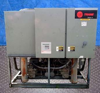
Trane Rotary Screw Air Cooled Chiller 100 Ton
|
|
|
- Timothy Hamilton
- 6 years ago
- Views:
Transcription


 Trane Compressors, Model")
 Fans, 2-1/2 hp, 1.")

1 Trane Rotary Screw Air Cooled Chiller 100 Ton Mfg: Trane Model: RTAA 1004XF01A1COKBDFN Stock No. DBPF255.5 Serial No. U96D33776 Trane Rotary Screw Air Cooled Chiller 100 Ton. Model RTAA 1004XF01A1COKBDFN S/N U96D (2) Trane Compressors, Model CHHN050, 84 amp draw, 460 volt each. (10) Fans, 2-1/2 hp, 1.5 amp draw, 460 volt. Overall Dimensions 87 in. H x 207 in. L x 90 in. W.
2
3 Air-Cooled Series R Rotary Liquid Chiller Model RTAA 70 to 125 Tons Built for the Industrial and Commercial Markets August 2002
4 Features and Benefits You Like its chillers, Trane wants its relationships with customers to last. Trane is interested in maintaining long term, loyal relationships. This perspective means the point in time that a customer purchases a chiller is the beginning of a relationship, not the end. Your business is important, but your satisfaction is paramount. Designed by Customers. Trane s RTAA was designed with the end user s requirements in mind. Reliability, efficiency, sound, and physical size were primary design concerns in expanding the RTAA product line down to 70 tons. The result is a reliable chiller that will help you achieve your bottom line goals American Standard Inc. All rights reserved.


5 Contents Features and Benefits Model Number Description General Data Selection Procedure Application Considerations Performance Adjustment Factors Performance Data Electrical Data Jobsite Connections Controls Dimensional Data Weights Options Typical Wiring Diagrams Features Summary Mechanical Specifications The standard ARI rating condition (54/44 F and 95 F) and IPLV are ARI certified. All other ratings, including the following, are outside the scope of the certification program and are excluded: Glycol. 50 Hz. Remote evaporator models. Water Chiller Systems Business Unit 3
6 Features and Benefits Improvements The RTAA offers the same high reliability of its larger predecessor coupled with lowered sound levels, increased energy efficiency, and reduced physical footprint, all due to its advanced design, low speed/direct drive compressor and proven Series R performance. Some of the major advantages of the Model RTAA vs its larger predecessor are: Higher energy efficiency Lower sound levels Smaller physical footprint The Series R Model RTAA is an industrial grade design built for both the industrial and commercial markets. It is ideal for schools, hospitals, retailers, office buildings, Internet service providers and industrials. ASHRAE Standard 90.1 and RTAA World Class Energy Efficiency The importance of energy efficiency cannot be understated. Fortunately, ASHRAE has created a guideline emphasizing its importance. Nonetheless, energy is often dismissed as an operational cost over which the owner has little control. That perception results in missed opportunities for energy efficiency, reduced utility bills, and higher profits. Lower utility bills directly affect profitability. Every dollar saved in energy goes directly to the bottom line. Trane s RTAA is one way to maximize your profits. ASHRAE Standard 90.1 & Executive Order - New technology applied to the design, controls, and manufacturing have created superior efficiency levels in the RTAA that are unmatched in the industry. All Trane air-cooled chillers meet the new efficiency levels mandated by ASHRAE Standard This new standard requires higher efficiencies than past technologies can deliver. The US Federal Government has adopted standard 90.1 and, in some cases, requires even higher efficiencies. Federal Executive Order mandates energy consuming devices procured must be in the top 25% of their class or be at least 10% better than any product standard for that product. In the case of chillers, that product standard is ASHRAE Trane s RTAA meets and exceeds the efficiency requirements of 90.1, with some units meeting the stretch goals of Executive Order. Risk. The US Federal Government has adopted ASHRAE 90.1, and it s expected to be adopted domestically, if not globally, in the future. Domestic acceptance has already begun. Make sure that your chillers as well as your entire HVAC system complies, or you may be caught retrofitting your project with new equipment and paying extra design dollars if the code is adopted during construction. Precise Capacity Control. Trane s patented unloading system allows the compressor to modulate infinitely and exactly match building loads. At the same time chilled water temperatures will be maintained within +/- 1/2ºF of setpoint, potentially eliminating the need for external considerations to maintain temperatures. Reciprocating and screw chillers with stepped capacity control do well to maintain chilled water temperatures within 2ºF of setpoint. Stepped control also results in overcooling or undercooling your space because rarely does the capacity of the machine match the building load. The result can be 10% higher energy bills. Trane s RTAA optimizes the part load performance of your machine for energy efficiency, precise temperature control for all modes of operation, and your personal comfort regardless of changing conditions. 4

7 Features and Benefits Excellent Reliability A building environment is expected to be comfortable. When it is, no one says a word. If it s not that s a different story. The same is true with chillers. No one ever talks about chillers, yet alone compressors, until they fail, and tenets are uncomfortable and productivity is lost. Trane s helical rotary compressors have a first year reliability rate of over 99%, which means our chillers stay running when you need them. Screw compressors were designed to replace the inherent design flaws of a reciprocating compressor. Trane s helical rotary compressor has successfully achieved this goal, proven by the over 99% reliability rating of our compressor in the first year of operation. A good design like Trane s should maintain this level of reliability for several years of chiller operation. Not all screw compressors maintain a high reliability and Trane is the only manufacturer that will publish a reliability number. The point is to make sure that you are getting a reliable screw chiller design so that you don t end up with the downtime and lost earnings that the industry is trying to avoid by getting away from reciprocating technology. Fewer moving parts. Trane s helical rotary compressors have only two major rotating parts: the male and female rotor. A reciprocating compressor can have more than 15 times that number of critical parts. Multiples of pistons, valves, crankshafts, and connecting rods in a reciprocating unit all represent different failure paths for the compressor. In fact, reciprocating compressors can easily have a failure rate four times that of a helical rotor. Combine this with two to three reciprocating compressors for each helical rotary compressor on chillers of equal tonnage, and statistics tell you it s a matter of time before you lose a reciprocating compressor. Robust parts. Helical rotary compressors are precisely machined using state of the art processes from solid metal bar stock. Tolerances are maintained within a micron or less than a tenth of the diameter of a human hair. The resulting compressor is a robust yet highly sophisticated assembly capable of ingesting liquid refrigerant without risk of damage. Contrast this to a reciprocating compressor, which can be destroyed by a single slug of liquid. Series R Compressor Highlights Direct-drive, low speed for high efficiency and reliability. Simple design with only four moving parts, resulting in high reliability and low maintenance. Field serviceable compressor for easy maintenance. Precise rotor tip clearance for optimal efficiency. Suction gas-cooled motor, resulting in lower operating temperatures for increased motor life, and giving the capability for: Five-minute start-to-start/two minute stop-to-start capability, which allows for closer water loop temperature control. 5
. Low sound levels.")
8 Features and Benefits RTAA Chiller Highlights High Reliability, with over 99% compressor reliability rate in the first year of operation, and Adaptive Controls to keep the chiller on line producing cold water during adverse conditions. High Efficiency (all units exceed ASHRAE 90.1 efficiency standard). Low sound levels. Small footprint, with smallest required application space (operating footprint) in the industry. Years of research, testing, and successful applications. The Trane helical rotary compressor has amassed thousands of hours of testing, much of it at severe operating conditions. Not to mention the successful application of RTAA chillers for over 11 years, with a developed reputation as the industry standard. Trouble free startup through factory testing of compressor and completed chiller and factory installation of chiller accessories. +/- ½ F leaving water temperature control, resulting from PID feedforward controls, and linear load matching, also allowing for 10% flow rate change per minute while maintaining ± ½ F leaving water temperature control. Trane helical rotary screw compressor component parts versus reciprocating compressor components. 6
9 Features and Benefits Optimum Efficiencies Superior Full Load Efficiency Precise Rotor Tip Clearances Higher energy efficiency in a helical rotary compressor is obtained by reducing the rotor tip clearances. This reduces the leakage between high and low pressure cavities during compression. Precise rotor tip clearance is achieved with the latest manufacturing and machining technology. Trane is the first helical rotary compressor manufacturer to electronically check compressor parts machining accuracy as part of the standard production process. Optimized Compressor Parts Profiles Rotor and slide valves are unique designs, optimized for the air conditioning application. The rotors are designed for the pressure ranges in the air conditioning application. The unloader valve has a unique profile that resulted from computer performance modeling in typical part-load situations. Advanced Heat Transfer Surfaces Condenser and evaporator tubes use the latest heat transfer technology for increased efficiency. Great Part Load Efficiency With Trane Helical Rotary Screw Compressors and Electronic Expansion Valve Trane Helical Rotary Screw Compressor Means Superior Part Load Performance The air-cooled Series R chiller has great part-load performance. The combination patented unloading system on the general purpose compressor utilizes the variable unloading valve for the majority of the unloading function similar to that of the slide valve. The general purpose compressor also uses a step unloader valve which is a single unloading step to achieve the minimum unloading point of the compressor. The result of both of these designs is optimized part-load performance far superior to single reciprocating compressors. 7

10 Features and Benefits Electronic Expansion Valve When coupled with Trane s Adaptive Control microprocessor, our electronic expansion valve significantly improves part-load performance of the Series R chiller by minimizing superheat in the evaporator and allowing the chiller to run at reduced condensing temperatures. Chillers which use conventional TXV s must run at higher head pressures and consume more power than necessary at part-loads. Additionally, the electronic expansion valve and its controls allow much better stability and control over dynamic load and head changes. Under these conditions a conventional TXV may never achieve control stability and extended periods of TXV hunting and liquid slugging are common. Capacity Control and Load Matching Infinitely variable compressor modulation allows the compressor capacity to exactly match the building cooling load. Reciprocating and screw chillers that rely on stepped capacity control must run at a capacity equal to or greater than the load. Much of this excess capacity is lost because overcooling goes toward building latent heat removal, causing the building to be dried beyond normal comfort requirements. The result is an increase in chiller energy costs, particularly at the part-load conditions at which the chiller operates most of the time. PID Chilled Water Setpoint Control Through Slide Valve Modulation Maintain Chilled Water Supply Within ± 1 /2 F of Setpoint Chillers that have step capacity control typically can only maintain water temperature to around ± 2 F. With the air-cooled Series R chiller, maintaining temperature control has never been so accurate. Reduce Compressor Cycling Modulating capacity control offers better compressor reliability. Compressor cycling, typical of reciprocating compressors, will decrease compressor component life. Parts like motors and valves do not stand up well to excessive compressor cycling. Cutaway view of Trane s electronic expansion valve. 8
11 Features and Benefits Trouble-Free Installation, Start-Up and Operation Adaptive Control Microprocessor The RTAA chiller offers advanced microprocessor control and features the Adaptive Control microprocessor. So what is the Adaptive Control microprocessor? Adaptive Control means the Unit Control Module (UCM) directly senses the control variables that govern operation of the chiller: motor current draw, evaporator temperature, condenser temperature, etc. When any of the variables approaches a limit condition where the unit may be damaged or shut down on a safety, the UCM takes corrective action to avoid shutdown and keep the chiller operating. It does this through combined actions of compressor slide valve modulation, electronic expansion valve modulation and fan staging. Additionally, the UCM optimizes total unit power consumption during normal operating conditions. No other chiller control system in the marketplace duplicates this performance. The End Of Most Nuisance Trip-Outs And Unnecessary Service Calls? Unnecessary service calls and unhappy tenants are reduced. Only when the UCM has exhausted the corrective actions it can take and the unit is still violating an operating limit will the unit shut down. CONTROLS ON OTHER CHILLERS TYPICALLY SHUT DOWN THE CHILLER, QUITE PROBABLY JUST WHEN IT IS NEEDED THE MOST. For example: A typical five-year-old chiller with dirty coils might trip-out on high pressure cutout on a 100 F day in August. A hot day is just when comfort cooling is needed the most. In contrast, the aircooled Series R chiller with an Adaptive Control microprocessor will stage fans on, modulate electronic expansion valve, and modulate slide valve as it approaches a high pressure cutout. Thereby KEEPING THE CHILLER ON- LINE JUST WHEN YOU NEED IT THE MOST. 9
12 Features and Benefits Close Spacing Of Chiller The air-cooled Series R chiller has the tightest recommended side clearance in the industry, four feet, but that is not all. In situations where equipment must be installed with less clearance than recommended, such as frequently occurs in retrofit and rooftop applications, restricted air flow is common. Conventional chillers may not work at all. However, the air-cooled Series R chiller with Adaptive Control microprocessor will simply make as much chilled water as it can given the actual installed conditions, stay on line during any unforeseen abnormal conditions, and optimize its performance. Consult your Trane sales engineer for more details. Lower Service Expense Nuisance service calls are avoided. When there is a real problem that must be corrected, the UCM s extensive diagnostics help assure that the problem is quickly identified. Down time and service expense are minimized. And with the ability to communicate with the Trane Integrated Comfort system or a remote display panel, service problems can be identified and diagnosed remote to the installation. Factory Testing Means Trouble-Free Start-Up All air-cooled Series R chillers are given a complete functional test at the factory. This computer-based test program completely checks the sensors, wiring, electrical components, microprocessor function, communication capability, expansion valve performance and fans. In addition, each compressor is run tested to verify capacity and power consumption. The end result of this test program is that the chiller arrives at the jobsite fully tested and ready to go to work. Factory Installed And Tested Controls/ Options Speed Installation All Series R chiller options, including control power transformer, starter disconnect, low ambient control, ambient temperature sensor, low ambient lockout, communication interface and ice making controls are factory installed and tested. Some manufacturers send options in pieces to be field installed. With Trane, the customer saves on installation expense and has assurance that ALL chiller controls/options have been tested and will function as expected. 10
.")
13 Features and Benefits Superior Control Unit Control Module Trane s Adaptive Control microprocessor control system enhances the air-cooled Series R chiller by providing the very latest chiller control technology. State-of-the-Art Equipment The 70 to 125 ton air-cooled chillers offer the exclusive Trane Adaptive Control logic with the Clear Language Display (UCM). The Clear Language Display has various functions that allow the operator to read unit information and adjust setpoints. The Clear Language Display panel has 16 keys, the readout screen is a two-line, 40 character liquid crystal with a backlight. The backlight allows the operator to read the display in low-light conditions. Unit Control Module Features Equal Compressor Sequencing Trane maximizes both compressor and motor life by equalizing both the number of starts and the operating hours. The UCM will start the compressor with the least number of starts and turn off the compressor with the most operating hours. Conventional auto lead-lag control will equalize starts, but running hours will typically be unequal. Equalizing both starts and running hours will provide equal compressor wear. Internal Built-In Chiller Flow Protection The UCM automatically detects a no waterflow condition. An external flow switch is not required, which lowers costs versus typical chillers. Built-in flow protection also eliminates nuisance flow switch problems. Remote Clear Language Display Panel for 70 to 125-ton air-cooled chillers. 11

14 Features and Benefits Easy Chiller System Logging The UCM displays data required to log the chiller system. The following information is available either as standard or as an option with the Air- Cooled Series R Chiller microprocessor: Entering and leaving chilled water temperatures Ambient air temperature Evaporator and condenser refrigerant temperatures and pressures Compressor suction temperature Percent RLA for each compressor Percent line voltage Compressor starts and running hours Active setpoints: chilled water setpoint current limit setpoint ice termination setpoint low ambient lockout setpoint Over 90 diagnostic and operating conditions Part failure diagnostics: water temperature sensors refrigerant temperature sensors compressor contactors Remote Display Panel Trane air-cooled Series R ton chillers are available with a twisted pair connection to an optional remote display panel. Chiller operation can be controlled similarly to the control interface on the chiller itself. Through a twisted pair of wires the unit can be turned on or off, change the chilled water setpoint, and display over 90 operating and diagnostic conditions. The remote display panel can be mounted indoors so access to chiller information is just steps away, eliminating any need to go outdoors or on the roof. The clear language display for chiller sizes of tons has the ability to control multiple units. In a multiple unit configuration, the Remote Clear Language Display Panel has the capability to communicate with up to four units. Each unit requires a separate communication link with the Remote Display Panel. Easy Interface To The Building Management System Controlling the air-cooled Series R chiller with building management systems is state-of-the-art yet simple. Chiller inputs include: Chiller enable/disable Circuit enable/disable Chilled water setpoint Current limit setpoint Ice making enable Chiller outputs include: Compressor running indication Alarm indication (CKt 1/CKt2) Maximum capacity Trane Chiller Plant Manager/ICS The Tracer Chiller Plant Manager Building Management System provides building automation and energy management functions through stand- alone control. The Chiller Plant Manager is capable of monitoring and controlling your entire chiller plant system. Application software available: Time-of-day scheduling Duty cycle Demand limiting Chiller sequencing Process control language Boolean processing Zone control Reports and logs Custom messages Run time and maintenance Trend log Totalizing PID control loops And of course, Trane s Chiller Plant Manager Panel can be used on a stand- alone basis or tied into a complete building automation system. 12
15 Model Number Description Model Nomenclature Digit Number Tons Digits 1,2 Unit Model RT = Rotary Chiller Digit 3 Unit Type A = Air Cooled Digit 4 Development Sequence A = First Sequence Digit 5, 6 & 7 Nominal Capacity 070 = 70 tons 080 = 80 tons 090 = 90 tons 100 = 100 tons 110 = 110 tons 125 = 125 tons Digit 8 Unit Voltage A = 200/60/3 C = 230/60/3 D = 380/60/3 4 = 460/60/3 5 = 575/60/3 S = Special Digit 9 Compressor Starter Type Y = Y-Delta Closed Transition X = X-Line (Across the Line) S = Special Digit 10, 11 Design Sequence ** = Factory Input Digit 12 Evaporator Leaving Temperature 1 = Standard 40 to 65 F 2 = Low 0 to 39 F 3 = Ice-Making 20 to 65 F S = Special Digit 13 Condenser Coil Fin Material A = Aluminum S = Special 2 = Copper Fins 4 = CompleteCoat Digit 14 Agency Listing 0 = No Agency Listing 3 = C/UL Listing Digit 15 Control Interface C = Deluxe without Communication D = Deluxe with Communication Digit 16 Chilled Water Reset 0 = No Chilled Water Reset 1 = Based on Return Water Temperature 2 = Based on Outside Air Temperature Digit 17 Miscellaneous Factory Installed Options A = Architectural Louvered Panels B = Control Power Transformer C = Convenience Outlet D = Low Ambient Lockout Sensor F = Mech. Disconnect Switch G = Low Ambient Operation K = Coil Protection M = Access Guard P = Circuit Breaker (Single Point Power) Z = Circuit Breaker (Dual Point Power) Field Installed Options Q = Spring Isolators N = Neoprene Isolators R = Remote Display Panel 3 = 5 Year Compressor Warranty 8 = Architectural Louvered Panels 9 = Coil Protection 0 = Access Guard J = Remote Evaporator H = Sound Attenuator 13
16 General Data Table G-1 General Data RTAA Ton Size Compressor Quantity Nominal Size (1) (Tons) 35/35 40/40 50/40 50/50 60/50 60/60 Evaporator Water Storage (Gallons) (Liters) Min. Flow (GPM) (L/Sec) Max. Flow (GPM) (L/Sec) Condenser Qty of Coils Coil Length (In) 156/ / / / / /204 Coil Height (In) Fins/Ft Number of Rows Condenser Fans Quantity (1) 4/4 4/4 5/4 5/5 5/5 5/5 Diameter (In) Total Airflow (CFM) Nominal RPM Tip Speed (Ft/Min) Motor HP (Ea) Min Starting/Oper Ambient (2) Std Unit (Deg F) Low Ambient (Deg F) General Unit Refrigerant HCFC-22 HCFC-22 HCFC-22 HCFC-22 HCFC-22 HCFC-22 No. of Independent Refrigerant Circuits % Min. Load (3) Refrigerant Charge (1) (Lb) 58/58 61/61 73/61 73/73 98/73 98/98 (Kg) 26/26 28/28 34/28 34/34 44/34 44/44 Oil Charge (1) (Gallons) 2.5/ /2.5 3/2.5 3/3 3/3 3/3 (Liters) 10.6/ / / / / / Data containing information on two circuits shown as follows: ckt 1/ckt2. 2. Minimum start-up/operating ambient based on a 5 mph wind across the condenser. 3. Percent minimum load is for total machine at 50 F ambient and 44 F LWT, not each individual circuit. 14
17 Selection Procedure The chiller capacity tables, P-1 through P-12, cover the most frequently encountered leaving water temperatures. The tables reflect a 10 F (6 C) temperature drop through the evaporator. For temperature drops other than 10 F (6 C), refer to Table F-1, and apply the appropriate Performance Data Adjustment Factors. For chilled brine selections, refer to Figures F-2 and 3 for Ethylene and Propylene Glycol Adjustment Factors. To select a Trane air-cooled Series R chiller, the following information is required: 1. Design load in tons of refrigeration 2. Design chilled water temperature drop 3. Design leaving chilled water temperature 4. Design ambient temperature Evaporator flow rates can be determined by using the following formulas: GPM = Tons x 24 Temperature Drop (Degrees F) OR L/S = kw (Capacity) x.239 Temperature Drop (Degrees C) NOTE: Flow rates must fall within the limits specified in Table G-1 (for GPM or for l/s). Selection Example Given: Required System Load = 115 Tons Leaving Chilled Water Temperature (LCWT) = 44 F Chilled Water Temperature Drop = 10 F Design Ambient Temperature = 95 F Evaporator Fouling Factor = To calculate the required chilled water flow rate we use the formula given below: GPM = 115 Tons x 24 = 276 GPM 10 F 2. From Table P-6 (RTAA Performance Data), an RTAA 125 at the given conditions will produce tons with a compressor power input of kw and a unit EER of To determine the evaporator pressure drop we use the flow rate (GPM) and the evaporator water pressure drop curves, Figure F-1. Entering the curve at 276 GPM, the pressure drop for a nominal 125 ton evaporator is 18 feet. 4. For selection of chilled brine units or applications where the altitude is significantly greater than sea level or the temperature drop is different than 10 F, the performance adjustment factors from Tables F-1, F-2, and/or F-3 should be applied at this point. For example: Corrected Capacity = Capacity (unadjusted) x Glycol Flow Rate Adjustment Factor 5. The final unit selection is: QTY (1) RTAA 125 Cooling Capacity = tons Entering/Leaving Chilled Water Temperatures = 54/44 F Chilled Water Flow Rate = 276 GPM Evaporator Water Pressure Drop = 18 feet Compressor Power Input = kw Unit EER = 9.8 Minimum Leaving Chilled Water Temperature Setpoint The minimum leaving chilled water temperature setpoint for water is 40 F. For those applications requiring lower setpoints, a glycol solution must be used. Contact the local Trane sales engineer for additional information. 15
18 Application Considerations Application Considerations Certain application constraints should be considered when sizing, selecting and installing Trane air-cooled Series R chillers. Unit and system reliability is often dependent upon properly and completely complying with these considerations. Where the application varies from the guidelines presented, it should be reviewed with your local Trane sales engineer. Unit Sizing Unit capacities are listed in the performance data section. Intentionally oversizing a unit to assure adequate capacity is not recommended. Erratic system operation and excessive compressor cycling are often a direct result of an oversized chiller. In addition, an oversized unit is usually more expensive to purchase, install, and operate. If oversizing is desired, consider using two units. Unit Placement 1. Setting The Unit A base or foundation is not required if the selected unit location is level and the base is strong enough to support the unit s operating weight as listed in Tables W-1 and W Isolation and Sound Emission The most effective form of isolation is to locate the unit away from any soundsensitive area. Structurally transmitted sound can be reduced by ELASTOMERIC vibration eliminators. Spring isolators have proven to be of little benefit on air-cooled Series R chiller installations and are not recommended. An acoustical engineer should always be consulted in critical sound applications. For maximum isolation effect, water lines and electrical conduit should also be isolated. Wall sleeves and rubber isolated piping hangers can be used to reduce the sound transmitted through water piping. To reduce the sound transmitted through electrical conduit, use flexible electrical conduit. State and local codes on sound emissions should always be considered. Since the environment in which a sound source is located affects sound pressure, unit placement must be carefully evaluated. Sound power levels for Trane air-cooled Series R chillers are available on request. 3. Servicing Adequate clearance for evaporator and compressor servicing should be provided. Recommended minimum space envelopes for servicing are located in the dimensional data section and can serve as a guideline for providing adequate clearance. The minimum space envelopes also allow for control panel swing and routine maintenance requirements. Local code requirements may take precedence. 4. Unit Location a. General Unobstructed flow of condenser air is essential to maintain chiller capacity and operating efficiency. When determining unit placement, careful consideration must be given to assuring a sufficient flow of air across the condenser heat transfer surface. Two detrimental conditions are possible and must be avoided if optimum performance is to be achieved: warm air recirculation and coil starvation. Warm air recirculation occurs when discharge air from the condenser fans is recycled back to the condenser coil inlet. Coil starvation occurs when free airflow to (or from) the condenser is restricted. Both warm air recirculation and coil starvation cause reductions in unit efficiency and capacity because of the higher head pressures associated with them. The air-cooled Series R chiller offers an advantage over competitive equipment in these situations. Performance is minimally affected in many restricted air flow situations due to its unique condensing coil geometry. Also, through its advanced Adaptive Control microprocessor logic, the chiller will attempt to stay on-line where competitive chillers would usually shut down. Trane s unique Adaptive Control microprocessor has the ability to understand the operating environment of the chiller and adapt to it by first optimizing its performance and second, staying on line through abnormal conditions. For example, high ambient temperatures combined with a restricted air flow situation will generally not cause the air-cooled Series R chiller to shut down. Competitive chillers would typically shut down on a high pressure nuisance cut-out in these conditions. Debris, trash, supplies, etc. should not be allowed to accumulate in the vicinity of the air-cooled Series R chiller. Supply air movement may draw debris into the condenser coil, blocking spaces between coil fins and causing coil starvation. Special consideration should be given to low ambient units. Condenser coils and fan discharge must be kept free of obstructions to permit adequate airflow for satisfactory unit operation. 16
19 Application Considerations b. Provide Vertical Clearance Vertical condenser air discharge must be unobstructed. While it is difficult to predict the degree of warm air circulation, a unit installed as shown on the left would have its capacity and efficiency significantly reduced. Performance data is based on free air discharge. c. Provide Lateral Clearance The condenser coil inlet must not be obstructed. A unit installed closer than the minimum recommended distance to a wall or other vertical riser may experience a combination coil starvation and warm air recirculation, resulting in unit capacity and efficiency reductions. Once again, the Adaptive Control microprocessor will allow the chiller to stay on line, producing the maximum available capacity, even at less than recommended lateral clearances. The recommended lateral clearances are depicted in the dimensional data section. These are estimates and should be reviewed with the local Trane sales engineer at the jobsite. d. Provide Sufficient Unit-to-Unit Clearance Units should be separated from each other by a sufficient distance to prevent warm air recirculation or coil starvation. The air-cooled Series R chiller has the lowest recommended unit-to-unit clearance in the industry, eight feet. Consult the local Trane sales engineer for applications concerning close spacing and restricted airflows. e. Walled Enclosure Installations When the unit is placed in an enclosure or small depression, the top of the fans should be no lower than the top of the enclosure or depression. If they are, consideration should be given to ducting the top of the unit. Ducting individual fans, however, is not recommended. Such applications should always be reviewed with the local Trane sales engineer. 17
20 Application Considerations Water Treatment Dirt, scale, products of corrosion and other foreign material will adversely affect heat transfer between the water and system components. Foreign matter in the chilled water system can also increase pressure drop and, consequently, reduce waterflow. Proper water treatment must be determined locally, depending on the type of system and local water characteristics. Neither salt nor brackish water is recommended for use in Trane aircooled Series R chillers. Use of either will lead to a shortened life to an indeterminable degree. The Trane Company encourages the employment of a reputable water treatment specialist, familiar with local water conditions, to assist in this determination and in the establishment of a proper water treatment program. The capacities given in the performance data section of this catalog are based on water with a fouling factor of For capacities at other fouling factors, see adjustment factors in Table F-1. Effect Of Altitude On Capacity Air-cooled Series R chiller capacities given in the performance data tables, P-1 through P-12, are for use at sea level. At elevations substantially above sea level, the decreased air density will decrease condenser capacity and, therefore, unit capacity and efficiency. The adjustment factors in Table F-1 can be applied directly to the catalog performance data to determine the unit s adjusted performance. Ambient Limitations Trane air-cooled Series R chillers are designed for year-round applications over a range of ambients. Chillers from tons offer operation for ambients from 25 to 115 F as standard, and will operate down to -10 F with the low ambient option. The minimum ambient temperatures are based on still conditions (winds not exceeding five mph). Greater wind velocities will result in a drop in head pressure, therefore increasing the minimum starting and operating ambient temperature. Once again, the Adaptive Control microprocessor will attempt to keep the chiller on-line when high or low ambient conditions exist, making every effort to avoid nuisance trip-outs and provide the maximum allowable tonnage. Waterflow Limits The minimum waterflow rates are given in Table G-1. Evaporator flow rates below the tabulated values will result in laminar flow causing freeze-up problems, scaling, stratification and poor control. The maximum evaporator waterflow rate is also given in the general data section. Flow rates exceeding those listed may result in excessive tube and baffle erosion. The evaporator can withstand up to 50 percent water flow reduction as long as this flow is equal or above the minimum gpm requirements. Variable Evaporator Flow Air-cooled Series R chillers have the capability to handle variable evaporator flow without losing leaving water temperature control. Flow rates can be varied up to 10% of design without decreasing the leaving water temperature control capabilities. Temperature Limits 1. Leaving Water Temperature Range Trane air-cooled Series R chillers have three distinct leaving water categories: standard, low temperature, and ice making. The standard leaving water temperature range is 40 to 65 F. Low temperature machines produce leaving water temperatures between 0 F and 39 F. Since water supply temperature setpoints from 0 to 39 F result in suction temperatures at or below the freezing point of water, a glycol solution is required for all low temperature machines. Ice making machines have a leaving water temperature range of 20 to 65 F. Ice making controls include dual setpoint controls and safeties for ice making and standard cooling capabilities. Consult your local Trane sales engineer for applications or selections involving low temperature or ice making machines. The maximum water temperature that can be circulated through an evaporator when the unit is not operating is 108 F. The evaporator becomes thermal stress limited at this temperature. 2. Supply Water Temperature Drop The performance data for the Trane aircooled Series R chiller is based on a chilled water temperature drop of 10 F. Temperature drops outside this range will result in unit performance that differs from that cataloged. For performance data outside the 10 F range, see Table F-1 for adjustment factors. Chilled water temperature drops from 6 to 18 F may be used as long as minimum and maximum water temperature and minimum and maximum flow rates are not violated. Temperature drops outside 6 to 18 F are beyond the optimum range for control and may adversely affect the microcomputer s ability to maintain an acceptable supply water temperature range. Further, temperature drops of less than 6 F may result in inadequate refrigerant superheat. Sufficient superheat is always a primary concern in any direct expansion refrigerant system and is especially important in a package chiller where the evaporator is closely coupled to the compressor. When temperature drops are less than 6 F, an evaporator runaround loop may be required. 18
21 Application Considerations Typical Water Piping All building water piping must be flushed prior to making final connections to the chiller. To reduce heat loss and prevent condensation, insulation should be installed. Expansion tanks are also usually required so that chilled water volume changes can be accommodated. A typical piping arrangement is shown in Figure A-1. Short Water Loops The proper location of the temperature control sensor is in the supply (outlet) water. This location allows the building to act as a buffer and assures a slowly changing return water temperature. If there is not a sufficient volume of water in the system to provide an adequate buffer, temperature control can be lost, resulting in erratic system operation and excessive compressor cycling. A short water loop has the same effect as attempting to control from the building return water. The Air-Cooled Series R ton chiller has excellent leaving chilled water control capabilities because of exceptional controls, EXV and linear unloading. However, it is still a good idea to make sure the evaporator water loop is sized sufficiently to help maintain temperature control. As a guideline, ensure the volume of water in the evaporator loop equals or exceeds two times the evaporator flow rate. For a rapidly changing load profile, the amount of volume should be increased. To prevent the effect of a short water loop, the following items should be given careful consideration: A storage tank or larger header pipe to increase the volume of water in the system and, therefore, reduce the rate of change of the return water temperature. Multiple Unit Operation Whenever two or more units are used on one chilled water loop, Trane recommends that their operation be controlled from a single control device, such as a Trane Tracer system. 1. Series Operation Some systems require large chilled water temperature drops (16 to 24 F). For those installations, two units with their evaporators in series are usually required. Control of the units should be from a common temperature controller to prevent the separate thermostats fighting one another and continually hunting. It is possible to control from the two individual unit controls, but a common temperature controller provides a positive method for preventing control overlap, more closely matches system load, and simplifies compressor lead-lag capability. 2. Parallel Operation Some systems require more capacity or standby capability than a single machine can provide. For those installations, two units with their evaporators in a parallel configuration are typical. The only effective way of controlling two units in parallel is with a single temperature controller. Two individual temperature controllers are not capable of providing reliable system control and will often result in unsatisfactory operation. Figure A-1 Recommended Piping Components For Typical Evaporator Installation Vents Valved Pressure Gauge Union Vibration Eliminator Water Strainer Gate Valve Drain Union Vibration Eliminator Flow Switch (Optional) Gate Valve Balancing Valve 19
22 Performance Adjustment Factors Table F-1 Performance Data Adjustment Factors Chilled Altitude Fouling Water Sea Level 2000 Feet 4000 Feet 6000 Feet Factor Temp. Drop CAP GPM KW CAP GPM KW CAP GPM KW CAP GPM KW Figure F-1 Evaporator Water Pressure Drops, Ton Units FLOW (L/s) 20
23 Performance Adjustment Factors Figure F-2 Ethylene Glycol Performance Factors Figure F-3 Propylene Glycol Performance Factors Figure F-4 Ethylene Glycol and Propylene Glycol Freeze Point 21
24 Performance Data Table P-1 60 Hz RTAA 70 Performance Data English Entering Condenser Air Temperature (Degrees F) LWT (Deg. F) Tons kw EER Tons kw EER Tons kw EER Tons kw EER Tons kw EER Notes: 1. Ratings based on sea level altitude and evaporator fouling factor of Consult Trane representative for performance at temperatures outside of the ranges shown. 3. kw input is for compressors only. 4. EER = Energy Efficiency Ratio (Btu/watt-hour). Power inputs include compressors, condenser fans and control power. 5. Ratings are based on an evaporator temperature drop of 10 F F performance data reflects Adaptive Control Microprocessor control algorithms. 7. Interpolation between points is permissible. Extrapolation is not permitted. 8. Rated in accordance with ARI Standard 550/ Metric Entering Condenser Air Temperature (Degrees C) LWT (Deg. C) kwo kwi COP kwo kwi COP kwo kwi COP kwo kwi COP Notes: 1. Ratings based on sea level altitude and evaporator fouling factor of Consult Trane representative for performance at temperatures outside of the ranges shown. 3. kwi input is for compressors only. 4. COP = Coefficient of Performance (kwo/kwi). Power inputs include compressors, condenser fans and control power. 5. Ratings are based on an evaporator temperature drop of 5.6 C F performance data reflects Adaptive Control Microprocessor control algorithms. 7. Interpolation between points is permissible. Extrapolation is not permitted. 8. Rated in accordance with ARI Standard 550/ Table P-2 60 Hz RTAA 80 Performance Data English Entering Condenser Air Temperature (Degrees F) LWT (Deg. F) Tons kw EER Tons kw EER Tons kw EER Tons kw EER Tons kw EER Notes: 1. Ratings based on sea level altitude and evaporator fouling factor of Consult Trane representative for performance at temperatures outside of the ranges shown. 3. kw input is for compressors only. 4. EER = Energy Efficiency Ratio (Btu/watt-hour). Power inputs include compressors, condenser fans and control power. 5. Ratings are based on an evaporator temperature drop of 10 F F performance data reflects Adaptive Control Microprocessor control algorithms. 7. Interpolation between points is permissible. Extrapolation is not permitted. 8. Rated in accordance with ARI Standard 550/ Metric Entering Condenser Air Temperature (Degrees C) LWT (Deg. C) kwo kwi COP kwo kwi COP kwo kwi COP kwo kwi COP Notes: 1. Ratings based on sea level altitude and evaporator fouling factor of Consult Trane representative for performance at temperatures outside of the ranges shown. 3. kwi input is for compressors only. 4. COP = Coefficient of Performance (kwo/kwi). Power inputs include compressors, condenser fans and control power. 5. Ratings are based on an evaporator temperature drop of 5.6 C F performance data reflects Adaptive Control Microprocessor control algorithms. 7. Interpolation between points is permissible. Extrapolation is not permitted. 8. Rated in accordance with ARI Standard 550/
25 Performance Data Table P-3 60 Hz RTAA 90 Performance Data English Entering Condenser Air Temperature (Degrees F) LWT (Deg. F) Tons kw EER Tons kw EER Tons kw EER Tons kw EER Tons kw EER Notes: 1. Ratings based on sea level altitude and evaporator fouling factor of Consult Trane representative for performance at temperatures outside of the ranges shown. 3. kw input is for compressors only. 4. EER = Energy Efficiency Ratio (Btu/watt-hour). Power inputs include compressors, condenser fans and control power. 5. Ratings are based on an evaporator temperature drop of 10 F F performance data reflects Adaptive Control Microprocessor control algorithms. 7. Interpolation between points is permissible. Extrapolation is not permitted. 8. Rated in accordance with ARI Standard 550/ Metric Entering Condenser Air Temperature (Degrees C) LWT (Deg. C) kwo kwi COP kwo kwi COP kwo kwi COP kwo kwi COP Notes: 1. Ratings based on sea level altitude and evaporator fouling factor of Consult Trane representative for performance at temperatures outside of the ranges shown. 3. kwi input is for compressors only. 4. COP = Coefficient of Performance (kwo/kwi). Power inputs include compressors, condenser fans and control power. 5. Ratings are based on an evaporator temperature drop of 5.6 C F performance data reflects Adaptive Control Microprocessor control algorithms. 7. Interpolation between points is permissible. Extrapolation is not permitted. 8. Rated in accordance with ARI Standard 550/ Table P-4 60 Hz RTAA 100 Performance Data English Entering Condenser Air Temperature (Degrees F) LWT (Deg. F) Tons kw EER Tons kw EER Tons kw EER Tons kw EER Tons kw EER Notes: 1. Ratings based on sea level altitude and evaporator fouling factor of Consult Trane representative for performance at temperatures outside of the ranges shown. 3. kw input is for compressors only. 4. EER = Energy Efficiency Ratio (Btu/watt-hour). Power inputs include compressors, condenser fans and control power. 5. Ratings are based on an evaporator temperature drop of 10 F F performance data reflects Adaptive Control Microprocessor control algorithms. 7. Interpolation between points is permissible. Extrapolation is not permitted. 8. Rated in accordance with ARI Standard 550/ Metric Entering Condenser Air Temperature (Degrees C) LWT (Deg. C) kwo kwi COP kwo kwi COP kwo kwi COP kwo kwi COP Notes: 1. Ratings based on sea level altitude and evaporator fouling factor of Consult Trane representative for performance at temperatures outside of the ranges shown. 3. kwi input is for compressors only. 4. COP = Coefficient of Performance (kwo/kwi). Power inputs include compressors, condenser fans and control power. 5. Ratings are based on an evaporator temperature drop of 5.6 C F performance data reflects Adaptive Control Microprocessor control algorithms. 7. Interpolation between points is permissible. Extrapolation is not permitted. 8. Rated in accordance with ARI Standard 550/
26 Performance Data Table P-5 60 Hz RTAA 110 Performance Data English Entering Condenser Air Temperature (Degrees F) LWT (Deg. F) Tons kw EER Tons kw EER Tons kw EER Tons kw EER Tons kw EER Notes: 1. Ratings based on sea level altitude and evaporator fouling factor of Consult Trane representative for performance at temperatures outside of the ranges shown. 3. kw input is for compressors only. 4. EER = Energy Efficiency Ratio (Btu/watt-hour). Power inputs include compressors, condenser fans and control power. 5. Ratings are based on an evaporator temperature drop of 10 F F performance data reflects Adaptive Control Microprocessor control algorithms. 7. Interpolation between points is permissible. Extrapolation is not permitted. 8. Rated in accordance with ARI Standard 550/ Metric Entering Condenser Air Temperature (Degrees C) LWT (Deg. C) kwo kwi COP kwo kwi COP kwo kwi COP kwo kwi COP Notes: 1. Ratings based on sea level altitude and evaporator fouling factor of Consult Trane representative for performance at temperatures outside of the ranges shown. 3. kwi input is for compressors only. 4. COP = Coefficient of Performance (kwo/kwi). Power inputs include compressors, condenser fans and control power. 5. Ratings are based on an evaporator temperature drop of 5.6 C F performance data reflects Adaptive Control Microprocessor control algorithms. 7. Interpolation between points is permissible. Extrapolation is not permitted. 8. Rated in accordance with ARI Standard 550/ Table P-6 60 Hz RTAA 125 Performance Data English Entering Condenser Air Temperature (Degrees F) LWT (Deg. F) Tons kw EER Tons kw EER Tons kw EER Tons kw EER Tons kw EER Notes: 1. Ratings based on sea level altitude and evaporator fouling factor of Consult Trane representative for performance at temperatures outside of the ranges shown. 3. kw input is for compressors only. 4. EER = Energy Efficiency Ratio (Btu/watt-hour). Power inputs include compressors, condenser fans and control power. 5. Ratings are based on an evaporator temperature drop of 10 F F performance data reflects Adaptive Control Microprocessor control algorithms. 7. Interpolation between points is permissible. Extrapolation is not permitted. 8. Rated in accordance with ARI Standard 550/ Metric Entering Condenser Air Temperature (Degrees C) LWT (Deg. C) kwo kwi COP kwo kwi COP kwo kwi COP kwo kwi COP Notes: 1. Ratings based on sea level altitude and evaporator fouling factor of Consult Trane representative for performance at temperatures outside of the ranges shown. 3. kwi input is for compressors only. 4. COP = Coefficient of Performance (kwo/kwi). Power inputs include compressors, condenser fans and control power. 5. Ratings are based on an evaporator temperature drop of 5.6 C F performance data reflects Adaptive Control Microprocessor control algorithms. 7. Interpolation between points is permissible. Extrapolation is not permitted. 8. Rated in accordance with ARI Standard 550/
27 Performance Data Table P-7 50 Hz RTAA 70 Performance Data English Entering Condenser Air Temperature (Degrees F) LWT (Deg. F) Tons kw EER Tons kw EER Tons kw EER Tons kw EER Tons kw EER Notes: 1. Ratings based on sea level altitude and evaporator fouling factor of Consult Trane representative for performance at temperatures outside of the ranges shown. 3. kw input is for compressors only. 4. EER = Energy Efficiency Ratio (Btu/watt-hour). Power inputs include compressors, condenser fans and control power. 5. Ratings are based on an evaporator temperature drop of 10 F F performance data reflects Adaptive Control Microprocessor control algorithms. 7. Interpolation between points is permissible. Extrapolation is not permitted. 8. Rated in accordance with ARI Standard 550/ Metric Entering Condenser Air Temperature (Degrees C) LWT (Deg. C) kwo kwi COP kwo kwi COP kwo kwi COP kwo kwi COP Notes: 1. Ratings based on sea level altitude and evaporator fouling factor of Consult Trane representative for performance at temperatures outside of the ranges shown. 3. kwi input is for compressors only. 4. COP = Coefficient of Performance (kwo/kwi). Power inputs include compressors, condenser fans and control power. 5. Ratings are based on an evaporator temperature drop of 5.6 C F performance data reflects Adaptive Control Microprocessor control algorithms. 7. Interpolation between points is permissible. Extrapolation is not permitted. 8. Rated in accordance with ARI Standard 550/ Table P-8 50 Hz RTAA 80 Performance Data English Entering Condenser Air Temperature (Degrees F) LWT (Deg. F) Tons kw EER Tons kw EER Tons kw EER Tons kw EER Tons kw EER Notes: 1. Ratings based on sea level altitude and evaporator fouling factor of Consult Trane representative for performance at temperatures outside of the ranges shown. 3. kw input is for compressors only. 4. EER = Energy Efficiency Ratio (Btu/watt-hour). Power inputs include compressors, condenser fans and control power. 5. Ratings are based on an evaporator temperature drop of 10 F F performance data reflects Adaptive Control Microprocessor control algorithms. 7. Interpolation between points is permissible. Extrapolation is not permitted. 8. Rated in accordance with ARI Standard 550/ Metric Entering Condenser Air Temperature (Degrees C) LWT (Deg. C) kwo kwi COP kwo kwi COP kwo kwi COP kwo kwi COP Notes: 1. Ratings based on sea level altitude and evaporator fouling factor of Consult Trane representative for performance at temperatures outside of the ranges shown. 3. kwi input is for compressors only. 4. COP = Coefficient of Performance (kwo/kwi). Power inputs include compressors, condenser fans and control power. 5. Ratings are based on an evaporator temperature drop of 5.6 C F performance data reflects Adaptive Control Microprocessor control algorithms. 7. Interpolation between points is permissible. Extrapolation is not permitted. 8. Rated in accordance with ARI Standard 550/
28 Performance Data Table P-9 50 Hz RTAA 90 Performance Data English Entering Condenser Air Temperature (Degrees F) LWT (Deg. F) Tons kw EER Tons kw EER Tons kw EER Tons kw EER Tons kw EER Notes: 1. Ratings based on sea level altitude and evaporator fouling factor of Consult Trane representative for performance at temperatures outside of the ranges shown. 3. kw input is for compressors only. 4. EER = Energy Efficiency Ratio (Btu/watt-hour). Power inputs include compressors, condenser fans and control power. 5. Ratings are based on an evaporator temperature drop of 10 F F performance data reflects Adaptive Control Microprocessor control algorithms. 7. Interpolation between points is permissible. Extrapolation is not permitted. 8. Rated in accordance with ARI Standard 550/ Metric Entering Condenser Air Temperature (Degrees C) LWT (Deg. C) kwo kwi COP kwo kwi COP kwo kwi COP kwo kwi COP Notes: 1. Ratings based on sea level altitude and evaporator fouling factor of Consult Trane representative for performance at temperatures outside of the ranges shown. 3. kwi input is for compressors only. 4. COP = Coefficient of Performance (kwo/kwi). Power inputs include compressors, condenser fans and control power. 5. Ratings are based on an evaporator temperature drop of 5.6 C F performance data reflects Adaptive Control Microprocessor control algorithms. 7. Interpolation between points is permissible. Extrapolation is not permitted. 8. Rated in accordance with ARI Standard 550/ Table P Hz RTAA 100 Performance Data English Entering Condenser Air Temperature (Degrees F) LWT (Deg. F) Tons kw EER Tons kw EER Tons kw EER Tons kw EER Tons kw EER Notes: 1. Ratings based on sea level altitude and evaporator fouling factor of Consult Trane representative for performance at temperatures outside of the ranges shown. 3. kw input is for compressors only. 4. EER = Energy Efficiency Ratio (Btu/watt-hour). Power inputs include compressors, condenser fans and control power. 5. Ratings are based on an evaporator temperature drop of 10 F F performance data reflects Adaptive Control Microprocessor control algorithms. 7. Interpolation between points is permissible. Extrapolation is not permitted. 8. Rated in accordance with ARI Standard 550/ Metric Entering Condenser Air Temperature (Degrees C) LWT (Deg. C) kwo kwi COP kwo kwi COP kwo kwi COP kwo kwi COP Notes: 1. Ratings based on sea level altitude and evaporator fouling factor of Consult Trane representative for performance at temperatures outside of the ranges shown. 3. kwi input is for compressors only. 4. COP = Coefficient of Performance (kwo/kwi). Power inputs include compressors, condenser fans and control power. 5. Ratings are based on an evaporator temperature drop of 5.6 C F performance data reflects Adaptive Control Microprocessor control algorithms. 7. Interpolation between points is permissible. Extrapolation is not permitted. 8. Rated in accordance with ARI Standard 550/
29 Performance Data Table P Hz RTAA 110 Performance Data English Entering Condenser Air Temperature (Degrees F) LWT (Deg. F) Tons kw EER Tons kw EER Tons kw EER Tons kw EER Tons kw EER Notes: 1. Ratings based on sea level altitude and evaporator fouling factor of Consult Trane representative for performance at temperatures outside of the ranges shown. 3. kw input is for compressors only. 4. EER = Energy Efficiency Ratio (Btu/watt-hour). Power inputs include compressors, condenser fans and control power. 5. Ratings are based on an evaporator temperature drop of 10 F F performance data reflects Adaptive Control Microprocessor control algorithms. 7. Interpolation between points is permissible. Extrapolation is not permitted. 8. Rated in accordance with ARI Standard 550/ Metric Entering Condenser Air Temperature (Degrees C) LWT (Deg. C) kwo kwi COP kwo kwi COP kwo kwi COP kwo kwi COP Ratings based on sea level altitude and evaporator fouling factor of Consult Trane representative for performance at temperatures outside of the ranges shown. 3. kwi input is for compressors only. 4. COP = Coefficient of Performance (kwo/kwi). Power inputs include compressors, condenser fans and control power. 5. Ratings are based on an evaporator temperature drop of 5.6 C F performance data reflects Adaptive Control Microprocessor control algorithms. 7. Interpolation between points is permissible. Extrapolation is not permitted. 8. Rated in accordance with ARI Standard 550/ Table P Hz RTAA 125 Performance Data English Entering Condenser Air Temperature (Degrees F) LWT (Deg. F) Tons kw EER Tons kw EER Tons kw EER Tons kw EER Tons kw EER Notes: 1. Ratings based on sea level altitude and evaporator fouling factor of Consult Trane representative for performance at temperatures outside of the ranges shown. 3. kw input is for compressors only. 4. EER = Energy Efficiency Ratio (Btu/watt-hour). Power inputs include compressors, condenser fans and control power. 5. Ratings are based on an evaporator temperature drop of 10 F F performance data reflects Adaptive Control Microprocessor control algorithms. 7. Interpolation between points is permissible. Extrapolation is not permitted. 8. Rated in accordance with ARI Standard 550/ Metric Entering Condenser Air Temperature (Degrees C) LWT (Deg. C) kwo kwi COP kwo kwi COP kwo kwi COP kwo kwi COP Notes: 1. Ratings based on sea level altitude and evaporator fouling factor of Consult Trane representative for performance at temperatures outside of the ranges shown. 3. kwi input is for compressors only. 4. COP = Coefficient of Performance (kwo/kwi). Power inputs include compressors, condenser fans and control power. 5. Ratings are based on an evaporator temperature drop of 5.6 C F performance data reflects Adaptive Control Microprocessor control algorithms. 7. Interpolation between points is permissible. Extrapolation is not permitted. 8. Rated in accordance with ARI Standard 550/
30 Performance Data Table P-13 ARI Part-Load Values (60 Hz) Unit % Load Tons EER IPLV RTAA RTAA RTAA RTAA RTAA RTAA Table P-14 ARI Part-Load Values (50 Hz) Unit % Load Tons EER IPLV RTAA RTAA RTAA RTAA RTAA RTAA
31 Electrical Data Table E-1 Electrical Data (50 & 60 Hz, 3 Phase) Unit Wiring Motor Data Fans Unit Rated # of Power Max. Fuse, HACR Rec. Time Compressor (Each) (Each) Control Size Voltage (9) Connections (1) MCA (3) Breaker or MOP (2,11) Delay or RDE (4) Qty RLA (5) LRA (8) Qty. kw FLA kw (7, 10) RTAA / / / / / / / / RTAA / / / / / / / / RTAA / / / / / / / / RTAA / / / / / / / / RTAA / / / / / / / / RTAA / / / / / / / / Notes: 1. As standard, all ton units require a single point power connection. 2. Max Fuse or HACR type breaker = 225 percent of the largest compressor RLA plus 100 percent of the second compressor RLA, plus the sum of the condenser fan FLA per NEC Use FLA per circuit, NOT FLA for the entire unit). 3. MCA - Minimum Circuit Ampacity percent of largest compressor RLA plus 100 percent of the second compressor RLA plus the sum of the condenser fans FLAs per NEC RECOMMENDED TIME DELAY OR DUAL ELEMENT (RDE) FUSE SIZE: 150 percent of the largest compressor RLA plus 100 percent of the second compressor RLA and the sum of the condenser fan FLAs. 5. RLA - Rated Load Amps - rated in accordance with UL Standard Local codes may take precedence. 7. Control kw includes operational controls only. Does not include evaporator heat tape. 8. LRA - Locked Rotor Amps - based on full winding (x-line) start units. LRA for wye-delta starters is 1/3 of LRA of x-line units. 9. VOLTAGE UTILIZATION RANGE: Rated Voltage Utilization Range A 115/60/1, 15 amp customer provided power connection is required to operate the unit controls. A separate 115/60/1, 15 amp customer provided power connection is also needed to power the evaporator heat tape ( volts). If the optional control power transformer is used, the customer needs only to provide a power connection for the evaporator heat tape. 11. If factory circuit breakers are supplied with the chiller, then these values represent Maximum Overcurrent Protection (MOP). 29
32 Jobsite Connections Table J-1 Customer Wire Selection Wire Selection Size Wire Selection Size Wire Selection Size to Main Terminal Block to Disconnect (1) to Circuit Breaker (1) Connector Connector Factory Mounted Internal Connector Unit Rated Terminal Size Wire Range Disconnect Size Wire Range Circuit Breaker Size (3) Wire Range Size Voltage Ckt 1 Ckt 1 Ckt 1 Ckt 1 Ckt 1 Ckt 1 RTAA / Amp Lug Size D 400 Amp Lug Size B 350 Amp Lug Size B 230/ Amp Lug Size D 400 Amp Lug Size B 300 Amp Lug Size B 380/ Amp Lug Size E 250 Amp Lug Size A 200 Amp Lug Size A 460/ Amp Lug Size E 250 Amp Lug Size A 150 Amp Lug Size A 575/ Amp Lug Size E 250 Amp Lug Size A 125 Amp Lug Size A 380/ Amp Lug Size E 250 Amp Lug Size A 150 Amp Lug Size A 400/ Amp Lug Size E 250 Amp Lug Size A 150 Amp Lug Size A 415/ Amp Lug Size E 250 Amp Lug Size A 150 Amp Lug Size A RTAA / Amp Lug Size D 400 Amp Lug Size B 400 Amp Lug Size B 230/ Amp Lug Size D 400 Amp Lug Size B 350 Amp Lug Size B 380/ Amp Lug Size E 250 Amp Lug Size A 225 Amp Lug Size A 460/ Amp Lug Size E 250 Amp Lug Size A 175 Amp Lug Size A 575/ Amp Lug Size E 250 Amp Lug Size A 150 Amp Lug Size A 380/ Amp Lug Size E 250 Amp Lug Size A 175 Amp Lug Size A 400/ Amp Lug Size E 250 Amp Lug Size A 175 Amp Lug Size A 415/ Amp Lug Size E 250 Amp Lug Size A 175 Amp Lug Size A RTAA / Amp Lug Size D 600 Amp Lug Size C 500 Amp Lug Size C 230/ Amp Lug Size D 400 Amp Lug Size B 450 Amp Lug Size C 380/ Amp Lug Size E 400 Amp Lug Size B 300 Amp Lug Size B 460/ Amp Lug Size E 250 Amp Lug Size A 225 Amp Lug Size A 575/ Amp Lug Size E 250 Amp Lug Size A 175 Amp Lug Size A 380/ Amp Lug Size E 250 Amp Lug Size A 225 Amp Lug Size A 400/ Amp Lug Size E 250 Amp Lug Size A 225 Amp Lug Size A 415/ Amp Lug Size E 250 Amp Lug Size A 225 Amp Lug Size A RTAA / Amp Lug Size D 600 Amp Lug Size C 600 Amp Lug Size C 230/ Amp Lug Size D 600 Amp Lug Size C 500 Amp Lug Size C 380/ Amp Lug Size E 400 Amp Lug Size B 300 Amp Lug Size B 460/ Amp Lug Size E 250 Amp Lug Size A 250 Amp Lug Size A 575/ Amp Lug Size E 250 Amp Lug Size A 200 Amp Lug Size A 380/ Amp Lug Size E 250 Amp Lug Size A 250 Amp Lug Size A 400/ Amp Lug Size E 250 Amp Lug Size A 250 Amp Lug Size A 415/ Amp Lug Size E 250 Amp Lug Size A 250 Amp Lug Size A RTAA / Amp Lug Size D 600 Amp Lug Size C 600 Amp Lug Size C 230/ Amp Lug Size D 600 Amp Lug Size C 600 Amp Lug Size C 380/ Amp Lug Size E 400 Amp Lug Size B 350 Amp Lug Size B 460/ Amp Lug Size E 400 Amp Lug Size B 300 Amp Lug Size B 575/ Amp Lug Size E 250 Amp Lug Size A 225 Amp Lug Size A 380/ Amp Lug Size E 400 Amp Lug Size B 300 Amp Lug Size B 400/ Amp Lug Size E 400 Amp Lug Size B 300 Amp Lug Size B 415/ Amp Lug Size E 400 Amp Lug Size B 300 Amp Lug Size B RTAA / Amp Lug Size D 600 Amp Lug Size C N/A N/A 230/ Amp Lug Size D 600 Amp Lug Size C 600 Amp Lug Size C 380/ Amp Lug Size E 400 Amp Lug Size B 350 Amp Lug Size B 460/ Amp Lug Size E 400 Amp Lug Size B 300 Amp Lug Size B 575/ Amp Lug Size E 250 Amp Lug Size A 225 Amp Lug Size A 380/ Amp Lug Size E 400 Amp Lug Size B 300 Amp Lug Size B 400/ Amp Lug Size E 400 Amp Lug Size B 300 Amp Lug Size B 415/ Amp Lug Size E 400 Amp Lug Size B 300 Amp Lug Size B Lug Size A = #4 to 350 MCM per phase Lug Size B = 2/0 to 250 MCM & 2/0 to 500 MCM per phase Lug Size C = (2) 400 MCM to 500 MCM per phase Lug Size D = (2) #4 to 500 MCM per phase Lug Size E = #6 to 400 MCM per phase Lug Size F = (2) #2 to 600 MCM per phase Lug Size G = (2) #1 to 500 MCM per phase Lug Size H = (4) #2 to 600 MCM per phase Notes 1. Non-fused unit disconnect and circuit breaker are optional. 2. Copper wire only, sized per N.E.C., based on nameplate minimum circuit ampacity (MCA). 3. Circuit Breaker sizes are for factory mounted only. Field installed circuit breakers need to be sized using HACR breaker recommendations from Table E-1. 30
33 Jobsite Connections Figure J-1 Typical Jobsite Wiring NOTES: 1. DASHED LINES INDICATE RECOMMENDED FIELD WIRING BY OTHERS. CHECK SALES ORDER TO DETERMINE IF WIRING IS REQUIRED FOR SPECIFIC OPTIONS. 2. ALL THREE PHASE MOTORS SUPPLIED WITH THE UNIT ARE PROTECTED UNDER PRIMARY SINGLE PHASE FAILURE CONDITIONS. 3. CAUTION - DO NOT ENERGIZE UNIT UNTIL CHECK OUT AND START-UP PROCEDURES HAVE BEEN COMPLETED. 4 THE FOLLOWING CAPABILITIES ARE OPTIONAL - THEY ARE IMPLEMENTED AND WIRED AS REQUIRED FOR A SPECIFIC SYSTEM APPLICATION. A ICE-MACHINE CONTROL (CANNOT BE USED WITH OPT. L) B COMMUNICATIONS INTERFACE D WYE-DELTA CLOSED TRANSITION STARTER E CONTROL POWER TRANSFORMER. H UNIT DISCONNECT, NON-FUSED J CHILLED WATER RESET - RETURN WATER K CHILLED WATER RESET - OUTDOOR AIR L CHILLED WATER RESET - ZONE AIR (CANNOT BE USED WITH OPT. A) S CHILLED WATER FLOW SWITCH (NOT REQUIRED FOR CHILLER PROTECTION) T REMOTE CLEAR LANGUAGE DISPLAY. (BUFFER FOR DISPLAY LOCATED IN UNIT CONTROL PANEL.) 5. AUXILIARY CONTROLS FOR A CUSTOMER SPECIFIED OR INSTALLED LATCHING TRIPOUT. THE CHILLER WILL RUN NORMALLY WHEN THE CONTACT IS CLOSED AND TRIP THE CHILLER OFF ON MANUALLY RESETTABLE DIAGNOSTIC WHEN THE CONTACT OPENS. MANUAL RESET IS ACCOMPLISHED AT THE LOCAL OR REMOTE CLEAR LANGUAGE DISPLAY. 6 AUXILIARY CONTROLS FOR A CUSTOMER SPECIFIED OR INSTALLED REMOTE AUTO/ STOP FUNCTION. THE CHILLER WILL RUN NORMALLY WHEN THE CONTACT IS CLOSED AND STOP THE CHILLER WHEN THE CONTACT IS OPEN. RE-CLOSURE OF THE CONTACT WILL PERMIT THE CHILLER TO AUTOMATICALLY RETURN TO NORMAL OPERATION. TO BE IN SERIES WITH WATER PUMP RELAY (3K21). 7 NORMALLY OPEN CONTACTS FOR REMOTE SHUTDOWN OR REFRIGERANT CIRCUIT OPERATION. THE REFRIGERANT CIRCUIT WILL GO THRU A NORMAL SHUTDOWN WHEN THE CONTACTS ARE CLOSED AND WILL AUTOMATICALLY RESUME NORMAL START AND RUN MODES WHEN CONTACTS ARE OPEN. WIRING 8 ALL CUSTOMER CONTROL CIRCUIT WIRING MUST HAVE A MINIMUM RATING OF 150 VOLTS. 9. ALL FIELD WIRING MUST BE IN ACCORDANCE WITH THE NATIONAL ELECTRICAL CODE (NEC), STATE, AND LOCAL REQUIREMENTS. OUTSIDE THE UNITED STATES, OTHER COUNTRIES APPLICABLE NATIONAL AND/OR LOCAL REQUIREMENTS SHALL APPLY. REQUIRED WIRING 10 COPPER WIRE ONLY SIZED PER N.E.C. BASED ON NAMEPLATE MINIMUM CIRCUIT AMPACITY (MCA). SEE CUSTOMER WIRE SELECTION TABLE WIRES, 115 VAC CIRCUIT. MINIMUM CONTACT RATING AT 115 VAC 5.9 VA INRUSH. 1.3 VA SEALED. 12 FOR UNITS WITHOUT THE CONTROL POWER TRANSFORMER (1T1) OPTION, THE CUSTOMER MUST PROVIDE CONTROL POWER OF 115 VAC, 60 HERTZ, SINGLE PHASE, 750 VA. THE CONTROL POWER TRANSFORMER (1T1) IS STANDARD ON 50 HERTZ UNITS. 13 FOR ALL UNITS, THE HEAT TAPE MUST BE POWERED FROM A SEPARATE CUSTOMER PROVIDED 115V, 60 HZ; OR 220V, 50 HZ, 420 WATT SOURCE. 31

34 Controls Microcomputer Controls A microcomputer-based controller controls the air-cooled Series R ton chiller. The microcomputer controller provides better control than past controls as well as several new, important benefits. Adaptive Control Microprocessor The microcomputer-based controller allows Trane to optimize controls around the chiller application and the specific components used in the air-cooled Series R chiller. For instance, the compressor protection system is specifically designed for the air-cooled Series R chiller. A new leaving chilled water temperature control algorithm maintains accurate temperature control, minimizes the drift from setpoint and provides better building comfort. This control, combined with linear compressor unloading, also allows the chiller to be applied in wider array of applications, including variable primary flow. The microcomputer control incorporates improved chiller start-up, load limiting, lead/lag, and compressor run time equalization functions into standard chiller operation. Interface with outside systems such as building automation controls is flexible and easy. 32
35 Controls Simple Interface With Other Control Systems Microcomputer controls afford simple interface with other control systems, such as time clocks, building automation systems and ice storage systems. Wiring to the unit can be as simple as two wires! This means you can have the flexibility to meet job requirements while not having to learn a complicated control system. Safety Controls A centralized microcomputer offers a higher level of machine protection. Since the safety controls are smarter, they limit compressor loading to avoid compressor or evaporator failures, thereby minimizing nuisance shutdown. The Unit Control Module (UCM) directly senses the control variables that govern the loading of the chiller: motor current draw, evaporator temperature, condenser temperature, etc. When any one of the variables approaches a limit condition where the unit may be damaged or shutdown on a safety, the UCM takes corrective action to avoid shutdown and keep the chiller operating. It does this through combined actions of compressor slide valve modulation, electronic expansion valve modulation and fan staging. The UCM optimizes total chiller power consumption during normal operating conditions. During abnormal operating conditions, the UCM will continue to optimize chiller performance by taking the corrective action necessary to avoid shutdown. This keeps cooling capacity available until the problem can be solved. Whenever possible, the chiller is allowed to perform its function; make chilled water. In addition, microcomputer controls allow for more types of protection such as over and under voltage. Overall, the safety controls help keep the building running and out of trouble. Monitoring And Diagnostics Since the microcomputer provides all control functions, it can easily indicate such parameters as leaving chilled water temperature and capacity stage. If a failure does occur, one of over 90 individual diagnostic and operating codes will be used to indicate the problem, giving more specific information about the failure. All of the monitoring and diagnostic information is displayed directly on a microcomputer display. Interface With The Trane Integrated Comfort System (ICS) When the air-cooled Series R chiller is used in conjunction with a Trane Tracer system, the unit can be monitored and controlled from a remote location. The air-cooled Series R chiller can be controlled to fit into the overall building automation strategy by using time of day scheduling, timed override, duty cycling, demand limiting, and chiller sequencing. A building owner can completely monitor the air-cooled Series R chiller from the Tracer system, as all of the monitoring information indicated on the microcomputer can be read off the Tracer system display. In addition, all the powerful diagnostic information can be read back at the Tracer system. Best of all, this powerful capability comes over a single twisted pair of wires! Air-cooled Series R chillers can interface with many different external control systems, from simple standalone units to ice making systems. Each unit requires a single-source, threephase power supply and two 115-volt power supplies. When an optional control power transformer is used, a single 115-volt supply handles the evaporator heat tape. For basic standalone applications, the interface with outside control is no different than for other Trane chillers. However, the RTAA units have many features that can be used to interface with building control systems. Standard Features 1. External Auto/Stop A jobsite provided contact closure will turn the unit on and off. Note: Do not use the chilled water pump to stop the chiller. 2. Chilled Waterflow Interlock A jobsite provided contact closure from a chilled water pump contactor or a flow switch is required and will allow unit operation if a load exists. This feature will allow the unit to run in conjunction with the pump system. 3. External Interlock A jobsite supplied contact opening wired to this input will turn the unit off and require a manual reset of the unit microcomputer. This closure is typically triggered by a jobsite supplied system such as a fire alarm. 4. Chilled Water Pump Control Unit controls provide an output to control chilled water pump(s). One contact closure to the chiller is all that is required to initiate the chilled water system. 5. Remote Running and Alarm Indication Contacts The unit provides three single-pole/ double-throw contact closures to indicate that a failure has occurred, if any compressors are running, or if the compressors are running at maximum capacity. These contact closures may be used to trigger jobsite supplied alarm lights or alarm bells. 33
36 Controls Optional Features 1. Communication Interface Capability for communication with one of the following control devices: a Trane Tracer Building Automation Systems b Remote Display 2. External Chilled Water Setpoint Allows the external setting independent of the front panel setpoint by one of three means: a) a remote resistor input (fixed or adjustable), b) a 2-10 VDC input, or c) a 4-20 ma input. 3. External Current Limit Setpoint Allows the external setting independent of the front panel set point by one of three means: a) a remote resistor input (fixed or adjustable), b) a 2-10 VDC input, or c) a 4-20 ma input. 4. Ice Making Control Provides interface with ice making control systems. 5. Chilled Water Temperature Reset Reset can be based on return water temperature or outdoor air temperature. The next section reviews the recommended interface with the following control systems: Stand-Alone Unit Integrated Comfort System Interface Non-Trane Building Automation Systems Ice Making Systems Remote Display Each system description includes a list of those features which must be used, those features which can be used and which external Trane device is required. 34

37 Controls Trane Controls System Tracer Summit controls Interface With The Trane Integrated Comfort System (ICS) Trane Chiller Plant Control The Tracer Summit Chiller Plant Building Management System with Chiller Plant Control provides building automation and energy management functions through stand-alone control. The Chiller Plant Control is capable of monitoring and controlling your entire chiller plant system. Application software available: Time-of-day scheduling Demand limiting Chiller sequencing Process control language Boolean processing Zone control Reports and logs Custom messages Run time and maintenance Trend log PID control loops And of course, the Trane Chiller Plant Control can be used on a stand-alone basis or tied into a complete building automation system. When the air-cooled Series R ton chiller is used in conjunction with a Trane Tracer Summit system, the unit can be monitored and controlled from a remote location. The air-cooled Series R ton chiller can be controlled to fit into the overall building automation strategy by using time of day scheduling, timed override, demand limiting, and chiller sequencing. A building owner can completely monitor the air-cooled Series R ton chiller from the Tracer system, since all of the monitoring information indicated on the unit controller s microcomputer can be read off the Tracer system display. In addition, all the powerful diagnostic information can be read back at the Tracer system. Best of all, this powerful capability comes over a single twisted pair of wires! Air- Modem Remote PC Workstation PC Workstation Notebook PC Workstation VariTrane Variable Air Volume Terminal Room temperature sensor VariTrane Variable Air Volume Terminal Room temperature sensor Building Control Unit Diffuser Diffuser Exhaust Fan cooled Series R ton chillers can interface with many different external control systems, from simple standalone units to ice making systems. Each unit requires a single-source, threephase power supply and a 115V/60Hz, 220V/50Hz power supply. The added power supply powers the evaporator heaters. A single twisted pair of wires tied directly between the air-cooled Series R ton chiller and a Tracer Summit system provides control, monitoring and diagnostic capabilities. Control functions Modular Climate Changer Air Handler LAN Air-cooled Series R Chiller Building Control Unit include auto/stop, adjustment of leaving water temperature setpoint, compressor operation lockout for kw demand limiting and control of ice making mode. The Tracer system reads monitoring information such as entering and leaving evaporator water temperatures and outdoor air temperature. Over 60 individual diagnostic codes can be read by the Tracer system. In addition, the Tracer system can provide sequencing control for up to 25 units on the same chilled water loop. Pump sequencing control can be provided from the Tracer system. Tracer ICS is not available in conjunction with the remote display or the external setpoint capability. 35
38 Controls Required Options 1 Tracer Interface Additional Options That May Be Used Ice Making Control External Trane Devices Required Tracer Summit, Tracer 100 System or Tracer Chiller Plant Control Ice Making Systems Controls An ice making option may be ordered with the air-cooled Series R chiller. The unit will have two operating modes, ice making and normal daytime cooling. In the ice making mode, the air-cooled Series R ton chiller will operate at full compressor capacity until the return chilled fluid temperature entering the evaporator meets the ice making setpoint. This ice making setpoint is manually adjusted on the unit s microcomputer. Two input signals are required to the air-cooled Series R ton chiller for the ice making option. The first is an auto/stop signal for scheduling and the second is required to switch the unit in between the ice making mode and normal daytime operation. The signals are provided by a remote job site building automation device such as a time clock or a manual switch. In addition, the signals may be provided over the twisted wire pair from a Tracer system. Required Options External Auto/Stop (Standard) Ice Making Control Additional Options That May Be Used Failure Indication Contacts Communications Interface (For Tracer Systems) Chilled Water Temperature Reset External Trane Devices Required None Note: All wiring outside the unit is supplied at the job site. 36

 2. Chilled Waterflow Interlock (Standard) Additional Features That May Be Used 1. Remote Running and Alarm Indication Contacts 2. External Interlock (Standard) 3.")
39 Controls Other Control Systems Interface With Other Control Systems Stand-alone Unit Interface to stand-alone units is very simple; only a remote auto/stop for scheduling is required for unit operation. Signals from the chilled water pump contactor auxiliary or a flow switch are wired to the chilled waterflow interlock. Signals from a timeclock or some other remote device are wired to the external auto/stop input. Note: Do not use the chilled water pump to stop the chiller. Required Features 1. External Auto/Stop (Standard) 2. Chilled Waterflow Interlock (Standard) Additional Features That May Be Used 1. Remote Running and Alarm Indication Contacts 2. External Interlock (Standard) 3. Chilled Water Temperature Reset External Trane Devices Required None Simple Interface With Other Control Systems Microcomputer controls afford simple interface with other control systems, such as time clocks, building automation systems and ice storage systems. This means you have the flexibility to meet job requirements while not having to learn a complicated control system. This setup has the same standard features as a stand-alone water chiller, with the possibility of having the following optional features. Alarm Indication Contacts The unit provides three single-pole/ double-throw contact closures to indicate that a failure has occurred, compressor on/off status, or if the compressors are running at maximum capacity. These contact closures may be used to trigger jobsite supplied alarm lights or alarm bells. PC Workstation Air-cooled Series R Chiller System Level Controller MP581 Programmable Controller MP581 Programmable Controller External Chilled Water Setpoint Allows the external setting independent of the front panel setpoint by one of two means: a) 2-10 VDC input, or b) 4-20 ma input. External Current Limit Setpoint Allows the external setting independent of the front panel setpoint by one of two means: a) 2-10 VDC input, or b) 4-20 ma input. Ice Making Control Provides interface with ice making control systems. Chilled Water Temperature Reset Reset can be based on return water temperature or outdoor air temperature. Pumps Boiler Ice Tanks 37
40 Controls Ice Making Systems An ice making option may be ordered with the air-cooled Series R chiller. The unit will have two operating modes, ice making and normal daytime cooling. In the ice making mode, the air-cooled Series R chiller will operate at full compressor capacity until the return chilled fluid temperature entering the evaporator meets the ice making set point. This ice making setpoint is manually adjusted on the unit s microcomputer. Two input signals are required to the air-cooled Series R chiller for the ice making option. The first is an auto/stop signal for scheduling and the second is required to switch the unit in between the ice making mode and normal daytime operation. The signals are provided by a remote jobsite building automation device such as a time clock or a manual switch. In addition, the signals may be provided over the twisted wire pair from a Tracer system. Required Features 1. External Auto/Stop (Standard) 2. Ice Making Control Additional Features That May Be Used 1. Remote Running and Failure Indication Contacts 2. Communications Interface (For Tracer Systems) 3. Chilled Water Temperature Reset (Indoor zone reset not available with ice making option). External Trane Devices Required None 38

41 Controls Remote Display The remote display option allows the operator to monitor chiller operation from a remote location. Over 60 essential chiller operating parameters can be transmitted between the unit control module on the chiller and the remote display via a bi-directional communications link. Only one twisted wire pair is required between the chiller and the remote display. In addition to monitoring chiller operation, alarms and unit diagnostics can be read from the remote display. Furthermore, the chilled water temperature setpoint can be adjusted and the chiller can be turned on or off from the remote display. Required Features 1. Communications Interface Additional Features That May Be Used 1. External Interlock (Standard) 2. Chilled Water Temperature Reset 3. Chilled Waterflow Interlock (Standard) 4. Remote Running and Failure Indication Contacts External Trane Devices Required 1. Remote Display Panel 39
42 Dimensional Data Figure D-1 RTAA Unit Dimensions UNIT SIZE A B C D E F G K m 1.213m 2.851m 102mm 4.940m 2.317m 1.549m 1.626m (1-7 3/8 ) (3-11 3/4 ) (9-4 1/4 ) (4 ) (16-2 1/2 ) (7-7 1/4 ) (5-1 ) (5-4 ) m 1.032m 3.499m 152mm 5.626m 2.661m 1.511m 1.930m (1-6 7/8 ) (3-4 5/8 ) (11-5 3/4 ) (6 ) (18-5 1/2 ) (8-8 3/4 ) (4-11 1/2 ) (6-4 ) NO. OF FANS PER UNIT UNIT SIZE NO. FANS STD UNIT VOLT & LOW VOLTAGE CONNECTIONS PANEL TYPE L M N P Q X-LINE CONTROL.889m.927m 1.206m 1.245m 1.283m PANEL (2-11 ) (3-0 1/2 ) (3-11 1/2 ) (4-1 ) (4-2 1/2 ) WYE DELTA CONTROL 76mm 114mm.39m.43m.47m PANEL (3 ) (4 1/2 ) (1-3 1/2 ) (1-5 ) (1-8 1/2 ) 40
43 Weights Table W-1 Packaged Unit Weights (Aluminum) Isolator Location Operating Shipping Unit Size Units Weight Weight RTAA 70 lbs kg RTAA 80 lbs kg RTAA 90 lbs kg RTAA 100 lbs kg RTAA 110 lbs kg RTAA 125 lbs kg Table W-2 Packaged Unit Weights (Copper) Isolator Location Operating Shipping Unit Size Units Weight Weight RTAA 70 lbs kg RTAA 80 lbs kg RTAA 90 lbs kg RTAA 100 lbs kg RTAA 110 lbs kg RTAA 125 lbs kg
44 Options Low Temperature Brine The unit controls can be factory set to handle low temperature brine applications (0 F to 39 F). Ice Making The unit controls can be factory set to handle ice making for thermal storage applications. Building Automation System Communication Interface Permits either bi-directional communication to the Trane Integrated Comfort system or permits remote chilled water setpoint and demand limiting by accepting a 4-20 ma or 2-10 Vdc analog signal. Remote Display In addition to controlling chiller operation from remote location, the remote display shall provide the capability to monitor unit alarms and diagnostics. Only one twisted pair is required between the chiller and the remote display. Remote Evaporator The remote evaporator is available as a standard option. This option provides an easily installed, pre-engineered method of installing the evaporator remotely indoors. The remote evaporator is skid-mounted and is shipped separately from the outdoor (condensing) unit. Refrigerant accessories, including electronic expansion valve, moisture indicating sightglass and removable core filter drier, are shipped with the evaporator skid. All refrigerant connections are routed to one end of the evaporator skid for easy connection. All electrical wiring is factory installed and routed to a terminal box (entering and leaving water temperature sensor, evaporator refrigerant temperature sensor and electronic expansion valve control wiring). Suction refrigerant temperature sensors (two) must be field installed in the field suction line piping next to the evaporator connections. Chilled Water Reset This option provides the control logic and field installed sensors for either load based (return water temperature) or temperature based (ambient or zone) reset of leaving chilled water temperature (requires Communication Package). Architectural Louvered Panels Louvered panels cover the complete condensing coil and the service area beneath the coils. Coil Protection Louvered panels which protect the condenser coils only. Access Protection A coated wire mesh which covers access area underneath the condenser coils. Control Power Transformer This option eliminates the need to run separate 115 volt control power to the unit. A control power transformer is factory installed and wired. A separate 115 volt power source is required for 60 Hz heat tape. Low Ambient Option The low ambient option consists of a variable speed drive on the first fan of each circuit and special control logic to permit low temperature operation. Low Ambient Lockout A factory installed ambient sensor and control logic can prevent starting below the recommended temperature. Non-Fused Power Disconnect Switch A non-fused disconnect switch with a through the door handle is provided to disconnect main power. Circuit Breaker A standard interrupting molded case capacity circuit breaker (UL approved) is available. The circuit breaker can also be used to disconnect the chiller from main power with a through the door handle and comes pre-wired from the factory with terminal block power connections. Neoprene Isolators Isolators provide isolation between chiller and structure to help eliminate frequency transmission. Neoprene isolators are more effective and recommended over spring isolators. Spring Isolators Spring isolators help isolate the chiller from the building structure. Condenser Corrosion Protection Copper fins and CompleteCoat are available on all size units for corrosion protection. Job site conditions should be matched with the appropriate condenser fin materials to inhibit coil corrosion and ensure extended equipment life. The CompleteCoat option provides fully assembled coils with a flexible dip and bake epoxy coating. Convenience Outlet Provides a 15 amp, 115 volt (60 Hz) convenience outlet on the unit. 42
45 Typical Wiring Diagram Tons NOTES: 1. DASHED LINES INDICATE RECOMMENDED FIELD WIRING BY OTHERS. PHANTOM LINES INDICATE ALTERNATE CIRCUITRY OR AVAILABLE SALES OPTION. CHECK SALES ORDER TO DETERMINE IF WIRING IS REQUIRED FOR SPECIFIC OPTIONS. 2. ALL THREE PHASE MOTORS SUPPLIED WITH THE UNIT ARE PROTECTED UNDER PRIMARY SINGLE PHASE FAILURE CONDITIONS. 3. CAUTION - DO NOT ENERGIZE UNIT UNTIL CHECK OUT AND START-UP PROCEDURES HAVE BEEN COMPLETED. 4 SEE INSERT A FOR RESISTOR CONNECTIONS TO PROGRAM AN EXTERNAL CHILLED WATER SETPOINT WHEN 4-20 ma OR A 2-10 VDC SIGNAL IS NOT USED. SEE THE OPERATORS MANUAL FOR RESISTOR VALUES. 5 SEE INSERT B FOR RESISTOR CONNECTIONS TO PROGRAM AN EXTERNAL CURRENT LIMIT SETPOINT WHEN 4-20 ma OR A 2-10 VDC SIGNAL IS NOT USED. SEE THE OPERATORS MANUAL FOR RESISTOR VALUES. 6 SEE INSERT C FOR CONTACTS (IN PLACE OF THE ZONE TEMP. SENSOR) FOR OPTIONAL ICE MACHINE CONTROL - OPTION A. 7. THE FOLLOWING CAPABILITIES ARE OPTIONAL - THEY ARE IMPLEMENTED AND WIRED AS REQUIRED FOR A SPECIFIC SYSTEM APPLICATION. A ICE-MACHINE CONTROL (CANNOT BE USED WITH OPT. L) B COMMUNICATIONS INTERFACE D WYE-DELTA CLOSED TRANSITION STARTER E CONTROL POWER TRANSFORMER. H UNIT DISCONNECT, NON-FUSED J CHILLED WATER RESET - RETURN WATER K CHILLED WATER RESET - OUTDOOR AIR L CHILLED WATER RESET - ZONE AIR (CANNOT BE USED WITH OPT. A) O LOW AMBIENT LOCKOUT S CHILLED WATER FLOW SWITCH (NOT REQUIRED FOR CHILLER PROTECTION) T REMOTE CLEAR LANGUAGE DISPLAY WIRING AND CONTACT REQUIREMENTS: 20. ALL FIELD WIRING MUST BE IN ACCORDANCE WITH THE NATIONAL ELECTRICAL CODE (NEC), STATE, AND LOCAL REQUIREMENTS. OUTSIDE THE UNITED STATES, OTHER COUNTRIES APPLICABLE NATIONAL AND/ OR LOCAL REQUIREMENTS SHALL APPLY. 21 FOR UNITS WITHOUT THE CONTROL POWER TRANSFORMER (1T1) OPTION, THE CUSTOMER MUST PROVIDE CONTROL POWER OF 115 VAC, 60 HERTZ, SINGLE PHASE, 750 VA ON 130 THRU 215 TON UNITS. THE CONTROL POWER TRANSFORMER (1T1) IS STANDARD ON 50 HERTZ UNITS. 22 FOR ALL UNITS, THE HEAT TAPE MUST BE POWERED FROM A SEPARATE CUSTOMER PROVIDED 115 VAC, 420 WATT SOURCE FOR 200/230/420/ HZ UNITS: 220 VAC, 420 WATT SOURCE FOR 346/1380/ HZ UNITS. FOR THE OPTIONAL HEAT RECOVERY HEAT TAPE IS 420 WATTS. 23 CUSTOMER SUPPLIED CONTACTS MUST BE COMPATIBLE WITH DRY CIRCUIT 12 VDC, 45 ma RESISTIVE LOAD. SILVER OR GOLD PLATED CONTACTS ARE RECOMMENDED VOLT OR LESS CIRCUIT. DO NOT RUN IN CONDUIT WITH HIGHER VOLTAGE CIRCUITS. USE #14-18 AWG. SEE SELECTION TABLE. 25 MINIMUM PILOT DUTY CONTACT RATING AT 115 VAC; 5.9 VA INRUSH, 1.3 VA SEALED. 26 FIELD WIRED ELECTRICAL LOADING IS NOT TO EXCEED THE FOLLOWING RATINGS: TERMINALS DEVICE VOLTAGE SEALED VA INRUSH VA 1U1-TB4-1,2 1U1K1,NO * 1U1-TB4-3 1U1K1,NC * 1U1-TB4-5,4 1U1K2,NO * 1U1-TB4-6,7 1U1K3,NC * 1U1-TB4-8,9 1U1K2,NO * 1U1-TB4-10,11 1U1K3,NC * *STANDARD PILOT DUTY RATING (35% POWER FACTOR). 27 WHEN CUSTOMER INPUT IS REQUIRED, REMOVE JUMPER AND INSTALL CUSTOMER WIRING. 28 CHILLED WATER PUMP CONTROL FROM TRANE UNIT UCM MODULE CHILLED WATER PUMP IS REQUIRED TO OPERATE A MINIMUM OF 1 MINUTE AFTER A COMMAND TO TERMINATE CHILLER OPERATION (UCM WILL PROVIDE THE DELAY CONTACTS). CHILLED WATER SYSTEM DEMAND SWITCH (5S2) IS CONNECTED TO THE UCM EXTERNAL AUTO/ STOP INPUT. NOTE: DO NOT USE THE CHILLED WATER PUMP TO STOP THE CHILLER. 29 AS SHIPPED 380/ HZ VOLT UNIT TRANSFORMER 1T1-(OPTIONAL) IS WIRED FOR 415 VOLT OPERATION. IF UNIT IS TO BE OPERATED ON A 380 VOLT POWER SUPPLY, RE-CONNECT AS SHOWN IN INSET D. REPROGRAM UNIT LINE VOLTAGE IN SERVICE SETTING MENU OF CLEAR LANGUAGE DISPLAY FROM 415 TO K1, K2, K3 RELAY OUTPUTS CAN BE PROGRAMMED TO PERFORM ALTERNATE FUNCTIONS. SEE INSTALLATION, OPERATION AND MAINTENANCE MANUAL FOR DETAILS. FUNCTION #1 IS SHOWN. 43
46 Typical Wiring Diagram Tons 44
47 Features Summary Trane RTAA Air-Cooled Series R Chiller Designed To Perform, Built To Last Reliability Proven Trane helical rotary screw compressor design for longer life and greater dependability. Fewer moving parts means less parts to fail. Typical reciprocating compressors have 4 times as many total parts and 15 times as many critical parts. Adaptive Control protects the chiller when any of the system variables approaches a limit condition that may damage the unit or cause a shutdown. The Unit Control Module takes corrective action to keep the unit running. Dual circuit design increases overall system reliability. Unlike reciprocating designs, this compressor can handle liquid slugging. Suction gas cooling allows the motor to operate at lower temperatures for longer life. Performance Superior full load efficiency. All units meet ASHRAE Standard. Excellent part load performance is achieved without resorting to manifolded multiple reciprocating compressors. Use of an electronic expansion valve significantly improves part load performance by minimizing superheat in the evaporator and allowing the chiller to run at reduced condensing temperatures. Unique compressor sequencing equalizes not only starts, but operating hours as well. Trouble-Free Operation and Start-Up Adaptive Control microprocessor keeps the Series R chiller on-line when others would shut down. Fewer nuisance trips means less expense from unnecessary service calls. Factory installed and tested options keep start-up time and expenses minimized. Easy interface capability with the Trane Integrated Comfort system via a single twisted pair of wires. Optional remote display panel simplifies chiller monitoring/ control. Packed stock availability for your ordering convenience. 45
48 Mechanical Specifications General Units are leak and pressure tested at 450 psig high side, 300 psig low side, then evacuated and charged. Packaged units ship with a full operating charge of oil and refrigerant. Unit panels, structural elements and control boxes are constructed of 12-gauge galvanized steel and mounted on a welded structural steel base. Unit panels and control boxes are finished with a baked on powder paint, and the structural base with an air dry paint. All paint meets the requirement for outdoor equipment of the U.S. Navy and other federal government agencies. Evaporator The evaporator is a tube-in-shell heat exchanger design with internally finned copper tubes roller expanded into the tube sheet. The evaporator is designed, tested and stamped in accordance with ASME for a refrigerant side working pressure of 300 psig. The evaporator is designed for a water side working pressure of 215 psig. Water connections are grooved pipe. The evaporator has one water pass with a series of internal baffles. Each shell includes a vent, a drain and fittings for temperature control sensors and is insulated with 3 /4-inch Armaflex II or equal insulation (K=0.26). Heat tape with thermostat is provided to protect the evaporator from freezing at ambient temperatures down to -20 F. Remote Evaporator The evaporator is a tube-in-shell heat exchanger, designed with internallyfinned copper tubes that are rolled expanded into the tube sheet. The evaporator is designed, tested and stamped for a refrigerant side working pressure of 300 psig, in accordance with ASME. The evaporator is designed for a water side working pressure of 215 psig. Water connections are victaulic. The evaporator has one water pass, with a series of internal baffles. Each shell includes a vent and drain connection, as well as factory-mounted entering and leaving water temperature control sensors and evaporator refrigerant temperature sensors. The evaporator is insulated with 3 /4-inch Armaflex II or equal insulation (K=0.26). The evaporator is skid-mounted and is shipped separately from the outdoor (condensing) unit. Refrigerant accessories, including electronic expansion valve, moisture indicating sightglass and removable core filter drier, are shipped with the evaporator skid. All refrigerant connections are routed to one end of evaporator skid for easy connection. All electrical wiring is factory installed and routed to a terminal box (entering and leaving water temperature sensor, evaporator refrigerant temperature sensor and electronic expansion valve control wiring). Suction refrigerant temperature sensors (two) must be field installed in the field suction line piping next to the evaporator connections. Condenser and Fans Air-cooled condenser coils have aluminum fins mechanically bonded to internally finned seamless copper tubing. The condenser coil has an integral subcooling circuit and also provides oil cooling for the compressor bearing and injection oil. Condensers are factory proof and leak tested at 506 psig. Direct-drive vertical discharge condenser fans are dynamically balanced. Threephase condenser fan motors with permanently lubricated ball bearing and internal thermal overload protection are provided. Standard units will start and operate down to 25 F ambient. Compressor and Lube Oil System The rotary screw compressor is semihermetic, direct drive, 3600 rpm, with capacity control slide valve, rolling element bearings, differential refrigerant pressure oil pump and oil heater. The motor is a suction gas cooled, hermetically sealed, two-pole squirrel cage induction motor. Oil separator and filtration devices are provided separate from the compressor. Check valves in the compressor discharge and lube oil system and a solenoid valve in the lube system are provided. 46
49 Mechanical Specifications Refrigeration Circuits Each unit has two refrigerant circuits, with one rotary screw compressor per circuit. Each refrigerant circuit includes a compressor suction and discharge service valve, liquid line shutoff valve, removable core filter drier, liquid line sight glass with moisture indicator, charging port and an electronic expansion valve. Fully modulating compressors and electronic expansion valves provide variable capacity modulation over the entire operating range. Unit Controls All unit controls are housed in a weathertight enclosure with removable plates to allow for customer connection of power wiring and remote interlocks. All controls, including sensors, are factory mounted and tested prior to shipment. All cataloged units are UL listed. Microcomputer controls provide all control functions including start-up and shut down, leaving chilled water temperature control, compressor and electronic expansion valve modulation, fan sequencing, antirecycle logic, automatic lead/lag compressor starting and load limiting. The unit control module, utilizing Adaptive Control microprocessor, automatically takes action to avoid unit shutdown due to abnormal operating conditions associated with low refrigerant temperature, high condensing temperature and motor current overload. Should the abnormal operating condition continue until a protective limit is violated, the unit will be shut down. Unit protective functions include loss of chilled water flow, evaporator freezing, loss of refrigerant, low refrigerant pressure, high refrigerant pressure, reverse rotation, compressor starting and running over current, phase loss, phase imbalance, phase reversal, and loss of oil flow. A menu driven digital display indicates over 20 operating data points including chilled water setpoint, current limit setpoint, leaving chilled water temperature, evaporator and condenser refrigerant pressures and temperatures. Over 60 diagnostic checks are made and displayed when a problem is detected. The digital display can be read and advanced on the unit without opening any control panel doors. Standard power connections include main three phase power and two 115 volt single phase power connections for control power and heat tape. Starters Starters are housed in a weathertight enclosure with removable cover plate to allow for customer connection of power wiring. Across-the-line starters are standard on all volt units. An optional Wye Delta closed transition starter (33 percent of LRA inrush) is available. Typically, Trane helical rotary compressors are up to full speed in one second when started across-the-line and have equivalent inrush with similar size reciprocating compressor with part wind starters. 47

50 Standard Conversion Table 48
Series R Rotary Liquid Chiller 70 to 400 Tons Air-Cooled
 RLC-DS-2 June1999 RLC-DS-2 Series R Rotary Liquid Chiller 70 to 400 Tons Air-Cooled Built For the Industrial and Commercial Markets 1 Features and Benefits Designed To Perform, Built To Last The Series
Series R Rotary Liquid Chiller
 Series R Rotary Liquid Chiller 70 to 125 Tons Water-Cooled and Condenserless Built For the Industrial and Commercial Markets November 1999 RLC-DS-4 Introduction Trane Series R Chiller Model RTWA The RTWA
Air-Cooled Series R Helical-Rotary Liquid Chiller
 Air-Cooled Series R Helical-Rotary Liquid Chiller Model RTAC 120 to 200 (400 to 760kw - 50 Hz) Built for the Industrial and Commercial Markets Introduction The new Trane Model RTAC Air-Cooled Helical-Rotary
Product Catalog. Air-Cooled Series R Chillers Model RTAC Nominal Tons (60 Hz) RLC-PRC006-EN. May 2012
 RLC-PRC006-EN. May 2012") Product Catalog Air-Cooled Series R Chillers Model RTAC 140-500 Nominal Tons (60 Hz) May 2012 RLC-PRC006-EN Introduction Trademarks Like its chillers, Trane wants its relationships with customers to last.
Product Catalog Air-Cooled Series R Chillers Model RTAC 140-500 Nominal Tons (60 Hz) May 2012 RLC-PRC006-EN Introduction Trademarks Like its chillers, Trane wants its relationships with customers to last.
Product catalogue RLC-PRC006D-EN
 Product catalogue Model RTAC Air-Cooled Series R Rotary Liquid Chiller RTAC Plus 140-350 Ton (60 Hz) RTAC Plus 140-300 Ton (50 Hz) Built For the Industrial and Commercial Markets January 2016 Introduction
Air-Cooled Liquid Chillers
 Air-Cooled Liquid Chillers 10 to 60 Tons January 2002 Introduction Air-Cooled Liquid Chillers Design and manufacturing excellence makes Trane a leader in the air-cooled chiller marketplace. For over 40
Air-Cooled Liquid Chillers 10 and 15 Tons Air-Cooled Chillers. 20 Through 60 Tons IntelliPak Air-Cooled Chillers
 CG-DS-1 July 1997 Second Reprint March 1999 CG-DS-1 Air-Cooled Liquid Chillers 10 and 15 Tons Air-Cooled Chillers 20 Through 60 Tons IntelliPak Air-Cooled Chillers 1 Features and Benefits 10-60 Tons Product
Air-Cooled Series R Helical-Rotary Liquid Chiller
 Air-Cooled Series R Helical-Rotary Liquid Chiller Model RTAC 120 to 400 (400 to 1500 kw 50 Hz) Built for the Industrial and Commercial Markets Model RTAC size 155 RLC-PRC005G-GB Introduction The Trane
Air-Cooled Scroll Chillers
 Product Catalog Air-Cooled Scroll Chillers Model CGAM - Made in USA 20 120 Nominal Tons (50 Hz and 60Hz) November 2009 CG-PRC017-EN Introduction Design and manufacturing excellence makes Trane a leader
Product Catalog. Air-Cooled Scroll Chillers Model CGAM - Made in USA Nominal Tons (50 Hz and 60 Hz) CG-PRC017-EN.
 CG-PRC017-EN.") Product Catalog Air-Cooled Scroll Chillers Model CGAM - Made in USA 20-130 Nominal Tons (50 Hz and 60 Hz) January 2012 CG-PRC017-EN Introduction Design and manufacturing excellence makes Trane a leader
Product Catalog Air-Cooled Scroll Chillers Model CGAM - Made in USA 20-130 Nominal Tons (50 Hz and 60 Hz) January 2012 CG-PRC017-EN Introduction Design and manufacturing excellence makes Trane a leader
60Hz. R134a HXWC SERIES. 205 to 560 Tons. Products That Perform...By People Who Care WATER-COOLED SEMI-HERMETIC SCREW COMPRESSOR WATER CHILLERS
 R Products That Perform...By People Who Care FORM NO: MS0455A WATER-COOLED SEMI-HERMETIC SCREW COMPRESSOR WATER CHILLERS R134a HXWC SERIES 205 to 560 Tons 60Hz INTRODUCTION Dunham-Bush's HXWC water cooled
Product Catalogue CG-PRC002E-EN. CGAD Liquid Chillers Air-Cooled Scroll Compressor 20 to 150 Tons. July Models: 50 / 60 Hz
 Product Catalogue CGAD Liquid Chillers Air-Cooled Scroll Compressor 20 to Tons Models: 50 / 60 Hz CGAD CGAD CGAD CGAD CGAD CGAD CGAD CGAD CGAD CGAD CGAD CGAD July 2012 CG-PRC002E-EN Introduction IMPORTANT:
Air-Cooled Global Chiller
 Product Manual PM 970 Group: Chiller Effective: June 1997 Supersedes: None Air-Cooled Global Chiller Type AGR 055AS through 100AS Reciprocating Compressor with R-22 60 hertz 1997 McQuay International Table
Call us today! (800)
") 150 TON AIR-COOLED CHILLER PA-ACCTR-150 Call us today! (800)341-4297 The 150-Ton portable chiller package features a Trane RTAC chiller unit. Trane leads the industry in providing some of the most reliable,
150 TON AIR-COOLED CHILLER PA-ACCTR-150 Call us today! (800)341-4297 The 150-Ton portable chiller package features a Trane RTAC chiller unit. Trane leads the industry in providing some of the most reliable,
XStream Water-cooled screw chillers and Water/Water Heat pumps
 XStream Water-cooled screw chillers and Water/Water Heat pumps Models 275 515 (935 to 1860 kw) 330 640 (1155 to 2220 kw) RLC-PRC058B-GB Table of Contents Introduction...4 Feature and benefits...5 Base
Call us today! (800)
") 500 TON AIR-COOLED CHILLER PA-ACCTR-500 Call us today! (800)341-4297 The 500-Ton portable chiller package features a Trane RTAC chiller unit. Trane leads the industry in providing some of the most reliable,
500 TON AIR-COOLED CHILLER PA-ACCTR-500 Call us today! (800)341-4297 The 500-Ton portable chiller package features a Trane RTAC chiller unit. Trane leads the industry in providing some of the most reliable,
Call us today! (800)
") PA-ACCTR-200 Call us today! (800)341-4297 The 200-Ton portable chiller package features a Trane RTAC chiller unit. Trane leads the industry in providing some of the most reliable, efficient and quiet chiller
PA-ACCTR-200 Call us today! (800)341-4297 The 200-Ton portable chiller package features a Trane RTAC chiller unit. Trane leads the industry in providing some of the most reliable, efficient and quiet chiller
MAC N-407 Air-Cooled Chiller
 MAC036-01-N-407 Air-Cooled Chiller Air-Cooled Chillers for Global Residential and Light Commercial MicroClimates MAC036 NOMENCLATURE BREAKDOWN MAC036-01 - N - 407 Refrigerant Type Air-Cooled Chiller 036=
Split System Condensing Units and Remote Chillers
 Split System Condensing Units and Remote Chillers 20 to 120 Tons 50 and 60 Hz November 2001 Introduction Trane 20 through 120-ton air-cooled condensing units are the leaders in the split system marketplace.
Installation Operation Maintenance
 Installation Operation Maintenance Series R Air-Cooled Helical-Rotary Liquid Chiller Model RTAC 120-400 (50 Hz) 400-1500 kw Contents General Information 6 Unit Inspection 6 Loose Parts Inventory 6 General
100 TON AIR-COOLED SCROLL PACKAGED. Call us today! (800) SPECIFICATIONS GENERAL DIMENSIONS ELECTRICAL DATA ADDITIONAL INFORMATION
 SPECIFICATIONS GENERAL DIMENSIONS ELECTRICAL DATA ADDITIONAL INFORMATION") 100 TON AIR-COOLED SCROLL PACKAGED SPECIFICATIONS Call us today! (800)341-4297 Trane Portable Packaged Air Conditioner units contain the best compressor technology available, in order to achieve the highest
100 TON AIR-COOLED SCROLL PACKAGED SPECIFICATIONS Call us today! (800)341-4297 Trane Portable Packaged Air Conditioner units contain the best compressor technology available, in order to achieve the highest
XStream Water-cooled screw chillers and Water/Water Heat pumps
 XStream Water-cooled screw chillers and Water/Water Heat pumps Refrigerant R134a Model 275-515 (940 to 1860 kw) Model 330 - K00 (1140 to 3670 kw) RLC-PRC058C-GB Table of Contents Introduction...3 Feature
MAC-120HE-03 Air-Cooled Chiller
 MAC-120HE-03 Air-Cooled Chiller 10 Ton / 120,000 BTUH Air-Cooled Chiller 380/415/460-3-50/60 1 HVAC Guide Specifications Air-Cooled Liquid Chiller Nominal Size: 10 Tons Multiaqua Model Number: MAC-120HE-03
MAC-060HE-01-L High Efficiency Air-Cooled Chiller Air-Cooled Chillers for Global Residential and Light Commercial Micro Climates Rev 1.
 MAC-060HE-01-L High Efficiency Air-Cooled Chiller Air-Cooled Chillers for Global Residential and Light Commercial Micro Climates Rev 1.2 HVAC Guide Specifications Air-Cooled Liquid Chiller with Low Ambient
MAC-036HE-02-L High Efficiency Air-Cooled Chiller Air-Cooled Chillers for Global Residential and Light Commercial Micro Climates Rev 1.
 MAC-036HE-02-L High Efficiency Air-Cooled Chiller Air-Cooled Chillers for Global Residential and Light Commercial Micro Climates Rev 1.1 HVAC Guide Specifications Air-Cooled Liquid Chiller with Low Ambient
MAC-048HE-01-L High Efficiency Air-Cooled Chiller Air-Cooled Chillers for Global Residential and Light Commercial Micro Climates Rev 1.
 MAC-048HE-01-L High Efficiency Air-Cooled Chiller Air-Cooled Chillers for Global Residential and Light Commercial Micro Climates Rev 1.1 HVAC Guide Specifications Air-Cooled Liquid Chiller with Low Ambient
Air-Cooled Screw Compressor Chillers
 Catalog Cat AGSD-1 Air-Cooled Screw Compressor Chillers Models AGS 225D to AGS 450D 210 to 450 Tons, 740 to 1580 kw Packaged or with Remote Evaporator or Chilled Water Pump Package R-134a, Hz Engineered
60 TON AIR-COOLED CHILLER. Call us today! (800) PA-ACCTR-60 GENERAL DIMENSIONS ELECTRICAL DATA 60 TON AIR-COOLED CHILLER FEATURES
 PA-ACCTR-60 GENERAL DIMENSIONS ELECTRICAL DATA 60 TON AIR-COOLED CHILLER FEATURES") 60 TON AIR-COOLED CHILLER PA-ACCTR-60 Call us today! (800)341-4297 The 60-Ton portable chiller package features a Trane CGAM chiller unit. Trane leads the industry in providing some of the most reliable,
60 TON AIR-COOLED CHILLER PA-ACCTR-60 Call us today! (800)341-4297 The 60-Ton portable chiller package features a Trane CGAM chiller unit. Trane leads the industry in providing some of the most reliable,
As a standard, heat exchangers are provided with flange water connections (BS Standard Table E). All evaporator are supplied fully insulated.
. All evaporator are supplied fully insulated.") NOMENCLATURE INTRODUCTION The HTT HWDX water-cooled chillers range is the latest addition to HTT s growing family of commercial products, featuring the most current technologies advances. The HWDX main
NOMENCLATURE INTRODUCTION The HTT HWDX water-cooled chillers range is the latest addition to HTT s growing family of commercial products, featuring the most current technologies advances. The HWDX main
MACH N-407 Heat Pump Air-Cooled Chiller
 MACH060-01-N-407 Heat Pump Air-Cooled Chiller Heat Pump Air-Cooled Chillers for Global Residential and Light Commercial Microclimates MACH NOMENCLATURE BREAKDOWN MACH-060-01 - N - 407 Refrigerant Type
AquaStream Air-Cooled Liquid Chillers
 Product Catalog AquaStream Air-Cooled Liquid Chillers Model CGAM 20 120 Tons - Made in USA December 2008 CG-PRC017-EN Introduction Design and manufacturing excellence makes Trane a leader in the air-cooled
Split System Condensing Units and Remote Chillers
 Split System Condensing Units and Remote Chillers 20 to 120 Tons 50 and 60 Hz June 2008 Introduction Trane 20 to 120-ton air-cooled condensing units are the leaders in the split system marketplace. Designed
Product Data. Features/Benefits ComfortLink control
 Product Data 30GTN,GTR Air-Cooled Reciprocating Liquid Chillers with ComfortLink Controls 50/60 Hz Nominal Capacities: 60 to 410 Tons 205 to 1445 kw Features/Benefits ComfortLink control Your link to a
Installation Operation Maintenance
 Installation Operation Maintenance Series R Air-Cooled Helical Rotary Liquid Chiller RTAD 085-180 (50Hz) Standard, Free Cooling and Heat Recovery models RTAD-SVX01F-E4 General information Foreword These
Product Catalog. Air-Cooled Scroll Chillers Model CGAM - Made in USA NominalTons (50 Hz and 60 Hz) CG-PRC017H-EN.
 CG-PRC017H-EN.") Product Catalog Air-Cooled Scroll Chillers Model CGAM - Made in USA 20-130 NominalTons (50 Hz and 60 Hz) February 2015 CG-PRC017H-EN Introduction Copyright Design and manufacturing excellence makestrane
Product Catalog Air-Cooled Scroll Chillers Model CGAM - Made in USA 20-130 NominalTons (50 Hz and 60 Hz) February 2015 CG-PRC017H-EN Introduction Copyright Design and manufacturing excellence makestrane
C. ASME Compliance: Fabricate and label water chiller heat exchangers to comply with ASME Boiler and Pressure Vessel Code: Section VIII, Division 1.
 SECTION 236426 - ROTARY-SCREW WATER CHILLERS PART 1 - GENERAL 1.1 SUMMARY A. This Section includes packaged, water cooled or air cooled as scheduled, electric-motor-driven, rotary-screw water chillers
Product Catalog. Air-Cooled Scroll Chillers Model CGAM Made in USA 20 to 130 NominalTons (60 Hz and 50 Hz) CG-PRC017N-EN.
 CG-PRC017N-EN.") Product Catalog Air-Cooled Scroll Chillers Model CGAM Made in USA 20 to 130 NominalTons (60 Hz and 50 Hz) July 2017 CG-PRC017N-EN Introduction Copyright Design and manufacturing excellence makestrane a
Product Catalog Air-Cooled Scroll Chillers Model CGAM Made in USA 20 to 130 NominalTons (60 Hz and 50 Hz) July 2017 CG-PRC017N-EN Introduction Copyright Design and manufacturing excellence makestrane a
AquaStream 3G Air-Cooled Liquid Chillers
 Product Catalog AquaStream 3G Air-Cooled Liquid Chillers Model CGAM CG-PRC019-E4 Introduction Design and manufacturing excellence makes Trane a leader in the air-cooled chiller marketplace. This tradition
Product Data. Features/Benefits. GEMINI 38AKS Commercial Air-Cooled Split Systems 50/60 Hz. 25 to 40 Nominal Tons (82.8 to 127.
 Product Data GEMINI 38AKS028-044 Commercial Air-Cooled Split Systems 50/60 Hz 25 to 40 Nominal Tons (82.8 to 127.0 kw) These dependable split systems match Carrier s indoor-air handlers with outdoor condensing
30RB/RQ 039S-160S Refrigerant HFC-410A Nominal cooling capacity kw Nominal heating capacity kw
 AIR-COOLED LIQUID CHILLER REVERSIBLE AIR-TO-WATER HEAT PUMP PRO-DIALOG PLUS 30RB/RQ 039S-60S Refrigerant HFC-40A Nominal cooling capacity 40-58 kw Nominal heating capacity 4-59 kw The new generation of
Microchannel REMOTE AIR COOLED CONDENSER WITH ELECTRONICALLY COMMUTATED AXITOP MOTORS. Technical Bulletin. Products that provide lasting solutions.
 Microchannel REMOTE AIR COOLED CONDENSER WITH ELECTRONICALLY COMMUTATED AXITOP MOTORS Technical Bulletin Products that provide lasting solutions. Krack Corporation has a long tradition of leadership and
GeneSys Air-Cooled Screw Compressor Chiller
 Installation and Maintenance Manual IMM AGSB- Group: Chiller Part Number: 330412001 Date: October 2005 Supersedes: IMM AGS-1 GeneSys Air-Cooled Screw Compressor Chiller AGS 230B through AGS 475B Hertz
Packaged Air-Cooled Water Chiller
 Installation, Operation and Maintenance Manual IOMM ALR-3 Group: Chiller Part Number: 330145710 Effective: September 2001 Supersedes: IM ALR-2 Packaged Air-Cooled Water Chiller ALR 110F - ALR 150F Refrigerant
Technical Development Program. COMMERCIAL HVAC PACKAGED EQUIPMENT Split Systems PRESENTED BY: Ray Chow Sigler
 Technical Development Program COMMERCIAL HVAC PACKAGED EQUIPMENT Split Systems PRESENTED BY: Ray Chow Sigler Menu Section 1 Section 2 Section 3 Section 4 Section 5 Section 6 Section 7 Introduction System
Water-cooled chillers with High Speed Centrifugal Compressors
 Water-cooled chillers with High Speed Centrifugal Compressors Refrigerant R134a 190-760 (395 to 2660 kw) Refrigerant R1234ze 135 G - 505 G (310 to 1820 kw) Table of Contents Introduction...3 Features and
Air-Cooled Split System Condensing Unit for Rooftop Systems and Air Handlers
 Catalog 221-1 Air-Cooled Split System Condensing Unit for Rooftop Systems and Air Handlers Model RCS 025C to 135C R-22/R-407C Refrigerant Contents Introduction............................... 3 The Condensing
RECORD SUBMITTAL COVER SHEET
 RECORD SUBMITTAL COVER SHEET PROJECT TITLE: AXCELLERATE PHARMA EQUIPMENT DESCRIPTION: CARRIER AQUASNAP AIR-COOLED CHILLER CH-1 OWNER: AXCELLERATE PHARMA MECHANICAL ENGINEER: ARDEN DATE: JUNE 27, 2014 SUBMITTED
Date: August 21, Proposal Number: G Engineer: Payment Terms: Net 30 Days
 Proposal Trane A Division of American Standard Inc. Prepared For: John Weston Desmet Ballestra Job Name: LAUER1 Biodiesel Chiller Pennsylvania Date: August 21, 2006 Proposal Number: G1-95502-1 Engineer:
SECTION SEQUENCE OF OPERATIONS FOR HVAC CONTROLS
 PART 1 - GENERAL SECTION 23 09 93 SEQUENCE OF OPERATIONS FOR HVAC CONTROLS 1.1 SUMMARY A. This Section includes control sequences for HVAC systems, subsystems, and other equipment. B. See Division 23 Section
RTHE Series R Helical Rotary Liquid Chiller Tons 60Hz
 Features Product and Benefits Catalog RTHE Series R Helical Rotary Liquid Chiller 75-255 Tons 60Hz January 2015 RTHE-PRC002-EN Introduction To meet a wide range of applications in the 75~255 ton water-cooled
Indoor liquid chiller with integrated hydraulic module
 Indoor liquid chiller with integrated hydraulic module Water-cooled: CGWN 205 206 207 208 209 210 211 212 213 214 215 Condenserless: CCUN 205 206 207 208 209 210 211 212 213 214 215 2 Contents Introduction
All series is using Hitachi scroll compressor, low vibration and high efficiency. Internal thermostat embedded compressors, and it can react quickly.
 HITACHI proudly presents to our customers this wide range of split system air conditioners, from 4HP to 20 HP which is designed for high and medium outdoor temperature and comply with almost any types
.2 Section Waste Management and Disposal.
 Issued 2005/06/01 Section 15624 Packaged Rotary Screw Water Chillers Page 1 of 5 PART 1 General 1.1 RELATED SECTIONS.1 Section 01330 Submittal Procedures..2 Section 01355 Waste Management and Disposal..3
Catalog Air Cooled Split System Condensing Units for Rooftop Systems and Air Handlers
 Air Cooled Split System Condensing Units for Rooftop Systems and Air Handlers Models RCS 025C through 135C 25 to 135 Tons R-22/R407C Refrigerant Catalog 221-1 Table of Contents Introduction.... 3 The Condensing
SCROLL LIQUID CHILLERS
 SCROLL LIQUID CHILLERS Application Manual Model NWC and NCC 15 TO 70 Tons (60 Hz) Water Cooled and Compressor 410A Chillers INTRODUCTION The NAPPS 410A Scroll Liquid Chiller Compressor Design Napps NWC
Water-Cooled Dual Compressor Screw Chiller
 Installation Manual IM 692-1 Group: Chiller Part Number: 629955 Effective: May 1997 Supersedes: IM663-1 IM683 IM692 Water-Cooled Dual Compressor Screw Chiller Installation Manual PFS 155C through PFS 210C,
CGAH 020~060 Liquid Chillers, Air Cooled, Axial Fan. Reliable, Efficient, and Quiet Operation. Reduced Maintenance. Fitted with Scroll Compressors.
 CGH 00~060 Liquid Chillers, ir Cooled, xial Fan. Reliable, Efficient, and Quiet Operation. Reduced Maintenance. Fitted with Scroll Compressors. From Components to System Technology Scroll compressor has
30RB Air-Cooled Liquid Chillers. Nominal cooling capacity 8-14 kw. Features. Quiet operation
 Air-Cooled Liquid Chillers www.eurovent-certification.com www.certiflash.com Quality Management Systems 0RB 008-05 Nominal cooling capacity 8- The new generation of Aquasnap liquid chillers was designed
B. Unit construction shall comply with ASHRAE 15 Safety Code, NEC, and ASME applicable codes (U.S.A. codes).
.") Guide Specifications PART 1 GENERAL 1.01 SYSTEM DESCRIPTION Microprocessor controlled, air-cooled liquid chiller utilizing scroll compressors, low sound fans, hydronic pump system and optional fluid storage
Guide Specifications PART 1 GENERAL 1.01 SYSTEM DESCRIPTION Microprocessor controlled, air-cooled liquid chiller utilizing scroll compressors, low sound fans, hydronic pump system and optional fluid storage
Exclusively published and distributed by Architectural Computer Services, Inc. (ARCOM) for the AIA
 for the AIA") Page 236423-1 Copyright 2009 by The American Institute of Architects (AIA) Exclusively published and distributed by Architectural Computer Services, Inc. (ARCOM) for the AIA Modified by MSU Physical Plant
Page 236423-1 Copyright 2009 by The American Institute of Architects (AIA) Exclusively published and distributed by Architectural Computer Services, Inc. (ARCOM) for the AIA Modified by MSU Physical Plant
SECTION SEQUENCE OF OPERATIONS FOR HVAC CONTROLS
 SECTION 23 09 93 SEQUENCE OF OPERATIONS FOR HVAC CONTROLS PART 1 - GENERAL 1.1 SUMMARY A. This Section includes control sequences for HVAC systems, subsystems, and equipment. B. See Division 23 Section
GeneSys. Air-Cooled Screw Compressor Chillers. Catalog
 Catalog Cat AGS-2 GeneSys Air-Cooled Screw Compressor Chillers Models AGS 120C to AGS 210C 110 to 210 Tons, 420 to 740 kw Packaged and with Remote Evaporator R-134a, 60 Hz Engineered for flexibility and
TECHNICAL GUIDE DESCRIPTION SPLIT-SYSTEM AIR-COOLED CONDENSING UNITS MODELS: HF-07 FEATURES B-0703
 TECHNICAL GUIDE SPLIT-SYSTEM AIR-COOLED CONDENSING UNITS MODELS: HF-07 DESCRIPTION These Sunline 2000 units are completely assembled, piped and wired at the factory to provide one-piece shipment and rigging.
30GH Air-Cooled Liquid Chillers 30GH Nominal cooling capacity kw
 Air-Cooled Liquid Chillers Nominal cooling capacity 21-94 kw Carrier is participating in the Eurovent Certification Programme. Products are as listed in the Eurovent Directory of Certified Products. The
SECTION ROTARY-SCREW WATER CHILLERS
 PART 1 GENERAL 1.01 SECTION INCLUDES A. Factory-assembled packaged chiller. B. Charge of refrigerant and oil. C. Controls and control connections. D. Chilled water connections. E. Electrical power connections.
MODELS LIST. Nominal Capacity RT
 1. MODELS LIST. NOMENCLATURE 3. FEATURES 4. PRODUCT DATA 5. PERFORMANCE CORRECTION 6. ANTIFREEZE 7. INSTALLATION 8. ELECTRICAL DATA 9. SCHEMATIC WIRING DIAGRAM 10.MICROPROCESSOR CONTROLLER 11.APPLICATION
TECHNICAL GUIDE DESCRIPTION SPLIT-SYSTEM AIR-COOLED CONDENSING UNITS. HA300, HB360, HB480 & HB thru 50 NOMINAL TONS (50 Hz)
") DESCRIPTION These units are completely assembled, piped and wired at the factory to provide one-piece shipment and rigging. Each unit is pressurized with a holding charge of refrigerant-22 for storage
DESCRIPTION These units are completely assembled, piped and wired at the factory to provide one-piece shipment and rigging. Each unit is pressurized with a holding charge of refrigerant-22 for storage
Product Catalog. Air-Cooled Series R Chillers Model RTAC 120 to 400 nominal tons (50 Hz) RLC-PRC039C-EN. October 2016
 RLC-PRC039C-EN. October 2016") Product Catalog Air-Cooled Series R Chillers Model RTAC 120 to 400 nominal tons (50 Hz) October 2016 RLC-PRC039C-EN Introduction Copyright Like its chillers, Trane wants its relationships with customers
Product Catalog Air-Cooled Series R Chillers Model RTAC 120 to 400 nominal tons (50 Hz) October 2016 RLC-PRC039C-EN Introduction Copyright Like its chillers, Trane wants its relationships with customers
SYSTEM DESIGN REQUIREMENTS
 P a g e 1 SYSTEM DESIGN REQUIREMENTS WFC-S SERIES WATER-FIRED SINGLE-EFFECT ABSORPTION CHILLERS / CHILLER-HEATERS Yazaki WFC-S Series water-fired chillers and chiller-heaters are available with nominal
30RB/RQ 039S-160S. Air-Cooled Liquid Chiller Reversible Air-To-Water Heat Pump Nominal cooling capacity: kw Nominal heating capacity: kw
 Air-Cooled Liquid Chiller Reversible Air-To-Water Heat Pump Nominal cooling capacity: 40-158 kw Nominal heating capacity: 41-159 kw Carrier China Carrier Corporation is a subsidiary of the United Technologies
Air Cooled Scroll Chiller / Heat Pump
 Air Cooled Scroll Chiller / Heat Pump SRA 145 Nominal Capacity 67.5 to 1080 kw Refrigerant: R407C and R134a Contents Features 1 MV7 Control 3 Physical Data R407c 5 Physical Data R134a 6 Unit Performance
Series R Helical Rotary Water-Cooled Liquid Chillers
 Product Catalog Series R Helical Rotary Water-Cooled Liquid Chillers Model 60-150 Tons - Made in USA January 2008 RLC-PRC029-EN Introduction To meet a wide range of applications in the 60 150 ton water-cooled
TITAN SERIES Complete Central Chiller & Pump Tank Package 20 to 70 Tons 20 F to 70 F
 Temperature Control Units Water & Oil - F Portable Chillers Air & Water-Cooled - 7 F Central Chillers Air & Water-Cooled Packages & Modules - 7 F Pump Tank Stations Chilled or Tower Water - gallons Cooling
Indoor liquid chiller with integrated hydraulic module
 Indoor liquid chiller with integrated hydraulic module Water-cooled: CGWN 205 206 207 208 209 210 211 212 213 214 215 Condenserless: CCUN 205 206 207 208 209 210 211 212 213 214 215 CG-PRC014G-GB Table
Product Data. Features/Benefits. OMNIZONE 50BRN,BZN Water-Cooled and Remote Air-Cooled Indoor Self-Contained Systems. 5 to 20 Nominal Tons
 Product Data OMNIZONE 50BRN,BZN006-024 Water-Cooled and Remote Air-Cooled Indoor Self-Contained Systems 5 to 20 Nominal Tons The 50BRN,BZN water-cooled and remote air-cooled indoor, self-contained units
Precise Temperature Control; Compact Footprint
 Precise Temperature Control; Compact Footprint The Conair EP1 Series Portable Chillers are designed for 1 to 3 ton applications. Available as air-cooled or water-cooled, with pump sizes from 1/4 to 3 Hp
Product Data. Features/Benefits. 38AH Commercial Air-Cooled Condensing Units 50/60 Hz. 20 to 130 Nominal Tons (63 to 390 Nominal kw)
") Product Data 38AH024-134 Commercial Air-Cooled Condensing Units 50/60 Hz 20 to 130 Nominal Tons (63 to 390 Nominal kw) a38-4143ef 38AH044-134 These dependable split systems match Carrier s 40RM or 39 Series
Product Data 38AH024-134 Commercial Air-Cooled Condensing Units 50/60 Hz 20 to 130 Nominal Tons (63 to 390 Nominal kw) a38-4143ef 38AH044-134 These dependable split systems match Carrier s 40RM or 39 Series
Product Data. Features/Benefits. 30GTN Packaged Air-Cooled Reciprocating Chillers 50/60 Hz
 Product Data 30GTN Packaged Air-Cooled Reciprocating Chillers 50/60 Hz 60 Hz 15 to 35 Nominal Tons (53 to 13 Nominal ) 50 Hz 15 to 30 Nominal Tons (53 to 106 Nominal ) MODEL 30GTN ( Shown) Features/Benefits
PACKAGED AIR COOLED Product Data Catalog
 PACKAGED AIR COOLED Product Data Catalog MODELS ASP-10A ASP-15A ASP-20A ASP-00P ASP-00F ASP-00G A MEMBER OF MARDUK HOLDING COMPANY, LLC The Leader in Modular Chillers ETL and CSA Approved CHILLER MODULES
Air-Cooled Screw Compressor Chiller
 Installation and Maintenance Manual IMM AGS-2 Group: Chiller Part Number: 331373301 Date: July 2008 Supersedes: March 2008 Air-Cooled Screw Compressor Chiller AGS 120CS/H - AGS 210CS/H, Packaged AGS 120CM/B
Scroll Water Cooled Chiller
 Scroll Water Cooled Chiller SRW145 Nominal Cooling Capacity 77 to 1232 kw Refrigerant: R407C and R134a Contents Features 1 MV7 Control 3 Physical Data 5 Unit Performance 8 Chiller Selection 9 Physical
Indoor liquid chiller and heat pump
 Indoor liquid chiller and heat pump CGWH Packaged Water-cooled liquid chiller and heat pump CCUH Condenserless unit Sizes: 115-120 - 125-225 - 230-235 - 240-250 CG-PRC008E-GB Table of Contents Introduction...4
TECHNICAL GUIDE. Description SPLIT-SYSTEM AIR-COOLED CONDENSING UNITS YD360, 480 & THRU 50 NOMINAL TONS YTG-B-0811
 Description These units are completely assembled, piped and wired at the factory to provide one-piece shipment and rigging. Each unit is pressurized with a holding charge of Refrigerant R-410A for storage
SECTION AIR COOLED WATER CHILLERS
 PART 1 GENERAL 1.1 SECTION INCLUDES A. Chiller package B. Charge of refrigerant and oil C. Controls and control connections D. Chilled water connections E. Starters F. Electrical power connections 1.2
SYNOPSIS. Part-Load Control Strategies for Packaged Rooftop Units. In this issue... Bin Hour Profile Charlotte, NC
 VOLUME ONE NUMBER THREE SYNOPSIS A N H V A C N E W S L E T T E R F O R B U I L D I N G O W N E R S A N D M A N A G E R S In this issue... Part-Load Strategies Why they re important.......... 1 What Things
Water-Cooled Screw Compressor Chillers
 Water-Cooled Screw Compressor Chillers Catalog 617-4 WGS 130AW To WGS 190AW, Packaged Water-Cooled Chiller WGS 130AA To WGS 190AA, Chiller with Remote Condenser 120 to 200 Tons, 420 to 700 kw R-134A, 60
FORM EG2 (405) Air Cooled Screw Liquid Chillers STYLE A FPO 28971AR. R134a kw 50 Hz
 Air Cooled Screw Liquid Chillers STYLE A FPO 28971AR. R134a kw 50 Hz") FORM 201.21-EG2 (405) Air Cooled Screw Liquid Chillers STYLE A FPO 28971AR R134a 492-879 kw 50 Hz TABLE OF CONTENTS Introduction...3 Specifications...4 Accessories and Options...7 Temperatures and Flows...10
FORM 201.21-EG2 (405) Air Cooled Screw Liquid Chillers STYLE A FPO 28971AR R134a 492-879 kw 50 Hz TABLE OF CONTENTS Introduction...3 Specifications...4 Accessories and Options...7 Temperatures and Flows...10
Water-Cooled Screw Compressor Chillers
 Catalog Cat WGS Water-Cooled Screw Compressor Chillers WGS 130AW To WGS 190AW, Packaged Water-Cooled Chiller WGS 130AA To WGS 190AA, Chiller with Remote Condenser 120 to 200 Tons, 420 to 700 kw R-134A,
SECTION PACKAGE AIR COOLED WATER CHILLER PART 1 GENERAL 1.01 SECTION INCLUDES. A. Chiller package. B. Charge of refrigerant and oil.
 1 1 1 1 1 1 1 1 0 1 0 1 SECTION 1 PACKAGE AIR COOLED WATER CHILLER PART 1 GENERAL 1.01 SECTION INCLUDES A. Chiller package. B. Charge of refrigerant and oil. C. Controls and control connections. D. Chilled
High Ambient / High Efficiency Series. R - 410a. 50Hz. Ducted Split Air Conditioners (5.0 kw kw)
") High Ambient / High Efficiency Series R - 410a 50Hz Ducted Split Air Conditioners (5.0 kw - 17.5 kw) ISO 9001 : 2008 ISO 14001 : 2004 ISO 18001 : 2007 R - 410a 50Hz Introduction: Established in the year
High Ambient / High Efficiency Series R - 410a 50Hz Ducted Split Air Conditioners (5.0 kw - 17.5 kw) ISO 9001 : 2008 ISO 14001 : 2004 ISO 18001 : 2007 R - 410a 50Hz Introduction: Established in the year
R22 R407C. 60Hz. ACHDX Series. 225 to 415 Tons. Air Cooled Horizontal Rotary Screw Chillers. Products That Perform...
 R Products That Perform...By People Who Care Form No: MS0464A Air Cooled Horizontal Rotary Screw Chillers R22 R407C Series 225 to 415 Tons 60Hz TABLE OF CONTENTS Page No. Page No. Nomenclature... 2 Physical
YCAL-SB Millennium AIR COOLED LIQUID CHILLER R407C REFRIGERANT. COOLING CAPACITIES 141 kw to 360 kw
 YCAL-SB Millennium AIR COOLED LIQUID CHILLER R407C REFRIGERANT COOLING CAPACITIES 141 kw to 360 kw YORK YCAL-SB Millennium air cooled scroll liquid chillers provide chilled liquid for all air conditioning
MHNCCX DX with Hot Water Heat Ceiling Concealed 4-Pipe Heat / Cool Fan Coil 12,000-36,000 BTUH
 MHNCCX DX with Hot Water Heat Ceiling Concealed 4-Pipe Heat / Cool Fan Coil 12,000-36,000 BTUH 318 MHNCCX NOMENCLATURE BREAKDOWN 4-Pipe Heat/Cool Ceiling Concealed Fan Coil MHNCCW- XX - XX Ceiling Concealed
Installation Operation Maintenance
 Installation Operation Maintenance Series R Air-Cooled Helical Rotary Liquid Chiller Models RTAD 85-125 (50Hz) RTAD-SVX01A-E4 American Standard Inc. 2001 RTAD-SVX01A-E4 Contents General Information 7 Literature
ENGINEERING GUIDE. Water-Cooled Self-Contained Units C-Series, Vertical
 ENGINEERING GUIDE Water-Cooled Self-Contained Units C-Series, Vertical TABLE OF CONTENTS Introduction...2 Product Overview...3 Nomenclature...4 General Data...5 Cooling Performance Data....6 Evaporator
INTRODUCTION. Special Applications of Package Air Conditioners. Instant Cooling Requirement in Wedding Ceremonies
 Pakistan s Largest Manufacturers of Air-Conditioners PACKAGE TYPE UNIT FOR MOBILE APPLICATIONS Provides Turnkey Projects Conceptual Planning to Commissioning of HVACR Projects THE LARGEST MANUFACTURER
CAS. Product Specifications. COMMERCIAL SPLIT SYSTEMS CONDENSING UNITS R 410A, 6 to 12.5 TONS BUILT TO LAST, EASY TO INSTALL AND SERVICE
 COMMERCIAL SPLIT SYSTEMS CONDENSING UNITS R 410A, 6 to 12.5 TONS BUILT TO LAST, EASY TO INSTALL AND SERVICE CAS Product Specifications Single stage cooling capacity control on all models with Micro channel
Water-Cooled Modular Chillers. Product Data Catalog. Standard and Total Access Modules MS010X, MS015X, MS020X, MS030X, MS040X, MS050X, MS070X, MS085X
 Product Data Catalog Standard and Total Access Modules MS010X, MS015X, MS020X, MS030X, MS040X, MS050X, MS070X, MS085X Variable Speed Total Access Modules MS010W, MS020W, MS030W, MS050W MS010V, MS020V,
How to Cut Chiller Energy Costs by 30%
 How to Cut Chiller Energy Costs by 30% Pre-packaged retrofit cuts centrifugal compressor chiller energy costs by 30% while reducing required maintenance and extending operating life at Duke Realty Corporation
The Digital Scroll Dryer
 The Digital Scroll Dryer A Design for True Performance and Energy Savings In Refrigerated Compressed Air Dryers Introduction Refrigerated compressed air dryers have been used for many years as a cost effective