SERVICE MANUAL. for Thermador Professional Series Built-in Wall Ovens. Models: PO301, POD301, PO302, POD302, PODC302, POM301, POMW301
|
|
|
- Roger Dean
- 6 years ago
- Views:
Transcription
1 SERVICE MANUAL for Thermador Professional Series Built-in Wall Ovens This manual contains information that is necessary for servicing the following Thermador electric built-in wall ovens: P0301, POD301, PO302, POD302, PODC302, POM301, POMW301 This manual is designed to be used by qualified service personnel only. Due to the complexity and the risk of high-voltage electrical shock, Thermador does not recommend that customers service their own units. Models: PO301, POD301, PO302, POD302, PODC302, POM301, POMW301
2 TABLE OF CONTENTS 1 General Models Features and Options Data Plate Warranty Operation Element Duty Cycles Sequence of Events Component Accessibility Serviceable from Front Serviceable from Top Serviceable from Rear Service and Repair Doors Removing and Replacing the Door(s) Door Latch/Motor Assembly Lamps Replacing Lamps High Temperature Cutout (HTC) Convection Fan and Ring Element Temperature Sensor Setting Temperature Offsets Broil Element(s) User Interface Removing the User Interface PC Control Module Power Supply Module Halogen Light Transformer(s) Convection Fan Motor Bake Element (Upper Oven) Removing the Bake Element Reinstalling the Bake Element Cooling Fan Motor (Upper Oven) Rotisserie Motor Error Codes How Error Codes are Communicated Error Code Table Service Mode Option Code Demo Mode Troubleshooting Wiring Diagrams and Schematics Additional References QuickFinder Technical Support Page 2 of 21


3 1 GENERAL There are 7 models in the 2007 Thermador Professional Built-in Wall Oven (BIWO) Series. A, C, and D oven cavities are utilized, and combination models include a built-in variation of the WD30 warming drawer and/or an MCE convection microwave. A user interface with stainless steel knobs and analog clock, fast preheat, 2-hour selfclean, a 12-pass broil element, and a heavy duty rotisserie are among the features offered. The control panel and door skins are grade 304 stainless steel. 1.1 Models PO301 PO302 POD301 POD302 PODC302 POM301 POMW301 Single oven without display Double oven without display Single oven with display Deluxe double oven with display Deluxe double oven with display and true convection in both cavities. Combination oven with microwave Triple combination oven with microwave and warming drawer 1.2 Features and Options Table 1 reflects the cavity configuration and the features available in each model. Table 1 Thermador Pro Series Features by Model 1.3 Data Plate The data plate reflecting model number and FD number is located on the underside of the interface control panel, as shown in Figure 1. Data plate Figure 1 Data plate Page 3 of 21
, different elements may be used and element duty cycles will vary. 1.")


4 The first 4 positions of the FD number reflect the year/month the product was produced. FD numbers that begin with 87 were built in 2007; 88 = 2008; 89 = 2009, etc. It is important to note that during regulation (regular cooking period that follows preheat), different elements may be used and element duty cycles will vary. 1.4 Warranty The product is warranted to be free from defects in materials and workmanship for a period of 12 months from date of purchase. Thermador will pay for all repair labor and replacement parts found to be defective due to materials and workmanship. Service must be provided by a Factory Authorized Service Agency, during normal working hours. Thermador assumes no responsibility for any repairs made on our products by anyone other than authorized service technicians. Find the complete product warranty statement in the Use and Care Manual. 2 OPERATION 2.1 Element Duty Cycles A new PID algorithm controls the way in which the elements cycle on and off during each cooking mode duty cycle. Every minute, the oven temperature is compared to the set point and a recalculation occurs, which results in varied element cycle times rather than the standard fixed 60-second cycle. During preheating, however, a 2-point control is still used and there is a defined element on-time. The tables below reflect the duration and start point by preheat mode, for cavity types A, C, and D. Technicians should have ample time to troubleshoot element problems during the ~10-minute preheat period. Tables 2, 3, and 4 Element duty cycle during preheat - by cavity 2.2 Sequence of Events Figures 2-8 that follow reflect the sequence of events that occurs during preheat for the various cooking modes. Page 4 of 21
5 Page 5 of 21
6 Figures 2-8 Sequence of events 3 COMPONENT ACCESSIBILITY 3.1 Serviceable from Front Door Door latch/motor assembly Cavity lamps High Temperature Cutout (HTC) Convection ring element and convection fan assembly (except motor) Temperature sensor Inner and outer broil elements Page 6 of 21
7 The User Interface is serviceable from the front after sliding the oven out from the wall ~ 4 inches. 3.2 Serviceable from Top The PC Control Module is serviceable from the top access panel after sliding the oven out from the wall ~16 inches. With the unit pulled completely away from the wall, the following components are serviceable from the top after removing the top panel: Halogen light transformers Terminal block Power supply 3.3 Serviceable from Rear With the unit pulled completely away from the wall and the back panel(s) removed, the following components can be serviced from the rear: Convection fan motor Bake element Cooling fan(s) Rotisserie motor 4 SERVICE AND REPAIR m CAUTION Sheet metal parts often have sharp edges. Avoid injury by handling these parts with care. Turn off the electrical power circuit to the oven at the main junction box before servicing this unit. For those checks requiring the use of electrical power, exercise extreme care. 4.1 Doors The doors on the double ovens are different, but interchangeable. The Thermador logo is located on the upper cavity door. The Pro Series handles are interchangeable with the Masterpiece Series handles. m CAUTION Avoid injury when removing and replacing oven doors. Be sure oven is cool enough for handling. Position hinges properly (see Figure 9). Grasp only by sides, not by the handle. Do not force door open or closed. Handle with care door weighs ~38 pounds Removing and Replacing the Door(s) To remove the door: 1. Open door completely. 2. Flip hinge levers back to open. 3. Close door until it remains open ~6 inches. 4. Using both hands, lift door up and out. To replace the door: 1. Position door as if it were open ~6 inches and insert hinges into slots. 2. Open door completely. 3. Flip hinge levers forward to close. 4. Close and open door to check operation. Page 7 of 21
 mechanism (120V 5W) has 2 switches - the door switch and the lock/unlock switch.")


8 Screw Tab Door Switch Lock/ Unlock Switch Figure 9 Opening (left) and closing (right) door hinges 4.2 Door Latch/Motor Assembly The motorized door latch (MDL) mechanism (120V 5W) has 2 switches - the door switch and the lock/unlock switch. The latch will automatically lock when mode and temperature selectors are set to CLEAN, and unlocks when the oven cools to ~490 F. It is serviced as an assembly. See Figure 10. If the latch becomes stuck in the locked position, turning the unit off and back on will open the latch if the cavity temperature <450. If latch is stuck in partially locked position, turn the mode selection knob to CLEAN, then to OFF. In models with a display, the latch can be tested in Service Mode. To remove the latch/motor assembly: 1. Remove 3 T20 screws securing trim piece to frame (do not remove 2 screws on either side of latch). 2. Pull trim forward about 1, then slightly to the right or left to clear the screw tab (see Figure 10). 3. Slip hands under trim and lift upper plate while sliding trim and latch toward you. Figure10 Door latch/motor assembly 4.3 Lamps Softlight is a feature in all oven Pro Series oven cavities, and a triac is used to switch the voltage. The lights will gradually fade in when turned on, and fade out when turned off. If this feature is not working properly, check the pin-out of X105 to verify that pin 6 (Softlight triac output) is utilized rather than pin 5 (relay output). On double ovens, verify that pin 4 on X205 (Softlight triac output) is utilized rather than pin 3 (relay output). If the pin-out is correct, replace the control module. There are 4 halogen lamps in each Pro Series cavity: 1 on each side, and 2 on the oven ceiling. Double oven lights are operated by a series of button pushes as shown in Table 5. LIGHT Button Upper Oven Lights Lower Oven Lights 1 st Touch ON OFF 2 nd Touch ON ON 3 rd Touch OFF ON 4 th Touch OFF OFF Table 5 Double oven lighting operation Page 8 of 21
9 4.3.1 Replacing Lamps Use 10-watt, 12-volt bi-pin halogen light bulbs (Part # ). Halogen bulbs must be handled with a clean, dry cloth. m CAUTION Turn off power to the oven at the fuse or breaker box light socket is live with door open. Be sure oven and lights are cool to the touch. Handle glass lenses carefully Side Lamps 1. Remove racks and rack support. 2. Firmly push the top mounting clip up and back (toward oven wall), until it releases the glass cover. 3. Pull the halogen bulb straight out from its socket. 4. Using a clean, dry cloth, insert the new bulb. 5. Reinsert the bottom of the glass cover (smooth side out) into the bottom clip, and firmly push the top of the cover into the upper clip until it snaps into place Ceiling Lamps 1. Unscrew glass cover. 2. Pull bulb straight out of its socket. 3. Using a clean, dry cloth, insert the new bulb. 4. Replace the glass cover. 4.4 High Temperature Cutout (HTC) The HTC is a normally closed switch that will interrupt the relay supply voltage in the event of a high temperature caused by a malfunctioning control module. be used to reach the reset button located on the top center of the HTC after the latch plate has been removed. 4.5 Convection Fan and Ring Element All models in the Pro Series are configured with one or more oven cavities that have both the convection fan and ring element (cavity type D). The lower cavity of the PODC302 has the convection fan only (cavity type C), and the lower cavities of the PO302 and POD302 offer strictly thermal heating (cavity type A). The fan may be used, with or without the ring element, to circulate heat evenly throughout the cavity in various cooking modes. The ring element (240V 2000W) and/or fan blade are easily accessed on the rear wall of the oven cavity behind the convection baffle. The convection fan motor is accessible only from the rear of the unit. Refer to the Element Strip Diagram to test the element at the control module, or: 1. Remove 2 T20 screws on either side of the element terminals. 2. Pull the element toward you so that terminal wires are inside the oven cavity. 3. Disconnect the wires from the terminals. 4. Use an ohmmeter to check for resistance of ~29 ohms. 4.6 Temperature Sensor Use an ohmmeter to check the resistance of the sensor. Normal ranges based on cavity temperature are shown in Table 6. The HTC is located in the plenum, behind and to the left of the MDL. Although it cannot be easily removed or replaced, a screwdriver can Page 9 of 21

10 display, press to enter a positive offset or to enter a negative offset. A +25 offset will result in a cavity temperature of 350 when the temperature knob is set to 325 for any of the cooking modes listed above. Similarly, a -25 offset will result in a cavity temperature of 300 when the temperature knob is set to 325. Table 6 Normal temperature sensor resistance readings On models with a display, real-time cavity temperature can be measured while in Service Mode (refer to the section entitled Service Mode or the Service Guide for instructions). After entering Service Mode, press the + MAX button once to display the real-time upper cavity temperature; a second press will display the upper cavity probe temperature. For lower oven readings, press the LIGHT button Setting Temperature Offsets If it becomes necessary to adjust the ongoing operating temperature of one or both oven cavities, offsets may be programmed on models with a display. Oven temperature offsets can be entered to raise or lower the cavity temperature during Bake, Convection Bake, Roast, Convection Roast, and Speed Convection modes. To access the 5 incremental offset selections, simultaneously press FAST PREHEAT and for cavity 1 or FAST PREHEAT and for cavity 2, for 5 seconds. After confirming that Upper or Lower is correctly illuminated in the 4.7 Broil Element(s) All single oven models, as well as the upper cavity of double oven models, have a 12-pass broil element that consists of an Inner Broil Element (240V 3600 W) and an Outer Broil Element (240V 1400W). In the lower cavity of double oven models, the 10-pass Inner Broil Element is used (240V 3600W). Refer to the Element Strip Diagram to test the element at the control module, or: 1. Remove the 4 T20 screws securing the element to the broil reflector. 2. Remove the 2 T20 screws on either side of the element terminals. 3. Pull the element toward you so that the terminal wires are inside the oven cavity. 4. Disconnect the wires from the inner broil element terminals. 5. Use an ohmmeter to check for resistance of ~16 ohms. 6. Disconnect the wires from the outer broil element terminals (if applicable). 7. Use an ohmmeter to check for resistance of ~41 ohms. 4.8 User Interface Figure 11 reflects the 5 variations of the T3 User Interface used in the Pro Series ovens. Three have an LED display: Page 10 of 21

, a power reset should be performed (preferably by the")
. 4. Repeat on the other side. 5.")

11 T3S1 POD301/POM301/POMW301, T3D1A PODC302, T3D1B POD302, and 2 without display: T3S2 PO301, T3D2 PO302. NOTICE The Pro User Interfaces require a relatively long start-up. There will not be a response if attempting to operate the unit during the first ~20 seconds after power-up. If the oven does not appear to be functioning properly (it will not heat or the display does not look normal), a power reset should be performed (preferably by the customer) before service is requested Removing the User Interface 1. Slide unit out from wall ~ 4 inches. 2. Remove 2 T20 bolts from each side. 3. Grasp one corner of the interface panel and lift upward, then pull it toward you (see Figure 12). 4. Repeat on the other side. 5. Disconnect the 3-wire yellow harness leading to PC Control Module. 1 Figure 11 T3 User Interface variations 2 The temperature selector is an encoder with 23 positions; position 0=OFF and position 22=CLEAN. Rotary switches are used for cooking mode selectors, and the number of switch positions will vary by model (either 6 or 12). The user interface control board, clock, and rotary setting devices are assembled onto a chassis and the entire assembly is serviced as a single unit. Figure 12 Each side of the user interface bracket has a tab that rests in a slot on the chassis u-profile. Page 11 of 21


12 To remove the User Interface Board and chassis from the stainless steel panel: 1. Remove all knobs. 2. Rotate clock bezel counterclockwise. 3. Remove 10 binding-head T20 screws securing the interface chassis to the bracket (these screws are unique to the interface notice the serrated underside). Rear X102 X101 X210 X204 X203 X103 X104 X105 X106 X110 X209 X107 X202 X201 X205 X206 X207 X1 X2 X3 After installing a new User Interface Board, always reset the oven and test. In some cases, a second reset may be necessary. Front Figure 14 Plug locations on the double oven control module 4.9 PC Control Module To access the PC Control Module, pull the unit out from the wall inches, and remove the access panel (3 T20 screws) on the top of the unit. See Figure 13. Figure 13 PC Control Module is visible after removing access panel. Whenever possible, conduct troubleshooting tests at the control module. Refer to Figures for plug and relay locations. NOTICE More than 75% of the control modules returned to the factory are fully functional. Before diagnosing a bad control module, be sure to disconnect and reconnect each wire/wire harness. Page 12 of 21


13 Figures 15 and 16 Relay locations on the double and single oven control modules Use Table 7 as a reference guide to the plugs, pins, and wire colors found on the PC Control Module. PLUG NO PIN NO FROM/TO COMMUNICATION X1 5-position card-edge Control Module to Power Supply Module connector - WH X2 3-position card-edge Control Module to User Interface Module connector - YE X3 3-position card-edge Control Module to Factory Service Port connector - YE X108* 2-position card-edge connector - WH/GN Control Module to Meat Probe UPPER/SINGLE CAVITY ELEMENTS X101 1-OR K102 Relay to Ring Element 2-BK L1 to K102 Relay 3-Blank 4-BK L1 to K104 Relay 5-Blank PLUG NO PIN NO FROM/TO 6-BU K104 Relay to Bake Element X102 1-YE K003 DLB Relay to Inner Broil Element 2-Not Used 3-Blank 4-RD L2 to K003 DLB Relay 5-RD L2 to K003 DLB Relay X103 1-BU K002 DLB Relay to Ring Element 2-RD L2 to K002 DLB Relay 3-Blank 4-RD L2 to K001 DLB Relay 5-Blank 6-OR K001 DLB Relay to Bake Element 7-VT K001 DLB Relay to Outer Broil Element X104 1-VT K107 Relay to Inner Broil Element 2-Blank 3-BK L1 to K107 Relay 4-BK L1 to K106 Relay 5-BK L1 to K106 Relay 6-Blank 7-Not Used 8-YE K106 Relay to Inner Broil Element X110 1-BU High Temperature Cutout (HTC) 2-Not Used 3-BU High Temperature Cutout (HTC) UPPER/SINGLE CAVITY SMALL LOAD X105 1-GR K121 Relay to Rotisserie Motor 2-YE K112 Relay to Convection Fan 3-BU/WH K114 Relay to Cooling Fan (L) 4-BU K115 Relay to Cooling Fan (H) 5-Not Used 6-BN Softlight Triac to Lights Page 13 of 21
14 PLUG NO PIN NO FROM/TO 7-BN K117 Relay to Motorized Door Latch (MDL) 8-RD L2 to K117 Relay X106 1-YE Door Switch 2-YE Door Switch 3-Not Used 4-YE/BK Latch Switch 5-OR/BK Latch Switch 6-VT/WH Door Switch 7-BN/WH Door Switch X107 1-WH Hall Effect Sensor 2-BK Hall Effect Sensor 3-RD Hall Effect Sensor 4-WH Temperature Sensor 5-WH Temperature Sensor X110 1-BU High Temperature Cutout (HTC) 2-Not Used 3-BU High Temperature Cutout (HTC) LOWER CAVITY ELEMENTS X201 1-BU ** K204 Relay to Ring Element 2-Blank 3-Blank 4-BK ** L1 to K204 Relay 5-BK L1 to K202 Relay 6-Blank 7-OR K202 Relay to Bake Element X202 1-RD L2 2-RD L2 to K006 DLB Relay 3-Not Used 4-Not Used 5-YE K006 DLB Relay to Broil Element X203 1-OR K004 DLB Relay to Bake Element PLUG NO PIN NO FROM/TO 2-Not Used 3-RD L2 to K004 DLB Relay 4-Blank 5-RD ** L2 to K005 DLB Relay 6-Blank 7-BU ** K005 DLB Relay to Ring Element X204 1-YE K206 to Broil Element 2-Not Used 3-Blank 4-BK L1 to K206 Relay 5-BK L1 to K206 Relay X210 1-BU High Temperature Cutout (HTC) 2-BU High Temperature Cutout (HTC) 3-Not Used LOWER CAVITY SMALL LOAD X205 1-YE ** K212 Relay to Convection Fan 2-RD L2 to K217 Relay 3-Not Used 4-BN Softlight Triac to Lights 5-Not Used 6-BN K217 Relay to Motorized Door Latch (MDL) X206 1-YE Door Switch 2-YE Latch Switch 3-YE/BK Latch Switch 4-OR/BK Latch Switch 5-Not Used 6-VT/WH Door Switch 7-BN/WH Door Switch X207 1-WH Hall Effect Sensor 2-Not Used 3-WH Temperature Sensor Page 14 of 21

15 PLUG NO PIN NO FROM/TO 4-RD Hall Effect Sensor 5-BK Hall Effect Sensor 6-WH Temperature Sensor X209 1-BU/WH X105-P3 to Cooling Fan (L) 2-BU X105-P4 to Cooling Fan (H) * POD models only ** PODC only Secondary LINE Terminals Primary LOAD Terminals Table 7 Plugs and pins on the PC control module To remove the PC Control Module: 1. Disconnect all wires. 2. Remove 1 T20 screw securing control module to chassis. 3. Slide module to the left to release the 3 tabs on the bottom of the module bracket from the 3 slots in the chassis. BN X105-6 X205-4 LINE LOAD OR Always reset the oven and test after changing the control module. In some cases, a second reset may be necessary Power Supply Module The power supply module (9.6V 12.5W) provides DC voltage to the control module and user interface Halogen Light Transformer(s) One transformer (120V-12V 40VA) is utilized per cavity. Triac switches 120 VAC to the transformer. There are 4 terminals on the new transformer, as shown in Figure 17. The resistance between the primary terminals should measure ~12.8 ohms and the resistance between the secondary terminals should measure ~0.32 ohms. WH Terminal Block Figure 17 Halogen light transformer 4.12 Convection Fan Motor The convection fan motor is 120V 29W. To test the motor, check for 120V across X105 / Pin 2 (upper/single) or X205 / Pin 1 (PODC) and chassis ground or neutral. The motor is accessible from the rear, after removing the rear outer sheet metal panel. 1. Disconnect the 2 wires from the motor terminals. 2. Remove 3 T20 screws from the arms of the motor assembly. 3. Use a tap and a hammer to dislodge the assembly from the clips that secure it to the rear of the unit. (Position tap on the arm secured by the rightmost clip.) OR Page 15 of 21
 at the control module, or disconnect the wires from the terminals and use a meter to check for a reading of ~29 ohms.")
16 4.13 Bake Element (Upper Oven) 2. After the element is beyond the front tab, remove the tool. Refer to the Strip Element Diagram to test the element (240V 2000W) at the control module, or disconnect the wires from the terminals and use a meter to check for a reading of ~29 ohms. To clear a path for removing the bake element, it is necessary to remove the vertical air channel(s) and disconnect wires. Before proceeding, note the position of the wires Removing the Bake Element 1. Pull wires out of plastic purse locks attached to upper and lower vertical air channels. 2. Remove upper air channel (4 T20 screws). 3. To create a pathway for the bake element, disconnect OR wires from upper and lower bake element terminals; YE from convection element terminals, BU/WH, BU, and WH from cooling fan motor. 4. Drape the wires/harnesses to the side so they do not block the element as it is pulled out. 5. Remove the screw between the element terminals. 3. Complete the installation. 4. Replace the plastic purse locks clips if they were removed from the vertical air channel Cooling Fan Motor (Upper Oven) Each 2-speed cooling fan (120V 28/41W) has 3 terminals (high speed, low speed, and neutral) and a Hall effect sensor. There is tape around the motor windings and the terminals are labeled N, H, and L for reference, as shown in Figure 18. Figure 18 Tape on cooling fan windings marked to designate terminals 6. Tuck insulation up into the oven wall as necessary. If the Hall effect sensor does not detect fan rotation, an error will display. To test the upper fan at the control module, check voltage across X105 / Pin 3 or 4 and neutral. 7. While holding element terminals, lift element upward to clear the outer edge of the compartment. 8. Hold element on both sides and lift upward as you slide it straight out Reinstalling the Bake Element There are 2 tabs inside the element cavity, and the front tab will prevent the element from going in all the way. Use a ruler or the vertical air channel (after removing plastic purse locks) as a tool to guide the element back in. 1. Place the tool inside the cavity, on top of the tab, then insert the element on top of the tool and slide it in. 1. Remove 3 T20 screws securing the fan to the mounting bracket. 2. Remove 3 T20 screws securing the bracket to the oven housing. 3. Slide bracket up and out to release it from the 2 tabs holding it in position. 4. Remove 3 T20 screws from the right side of the unit s top panel. 5. Lift the right corner of the top panel and remove the fan/motor. Page 16 of 21
. The maximum weight allowed on the rotisserie spit is 12 lbs.")


17 4.15 Rotisserie Motor LED1 communicates the left digit of the error code. If the rotisserie does not turn with the door closed and the oven in a rotisserie mode, replace the rotisserie motor (120V 12W). The maximum weight allowed on the rotisserie spit is 12 lbs. 5 ERROR CODES A Service Guide with error code information, wiring diagrams, and instructions for entering Service Mode (if applicable) is packed with every unit. Find it on the underside of the upper plenum access panel as shown in Figure 19. LED2 communicates the middle digit of the error code. LED3 communicates the right digit of the error code. For example, Error Code 115 is displayed by 1 blink of LED1, 1 blink of LED2, and 5 blinks of LED3. After a 1 second pause, the end of the code series will be signaled by LED1, LED2, and LED3 turning on for 1 second. The sequence will then repeat. On models with digital display, digital error codes will show to the right of the clock (see Figure 21), and blink at a frequency of 2 seconds on,.5 second off. Clear the error by touching the + and buttons simultaneously. E115 TOUCH TO CLEAR ERROR Figure 21 Error code 115 displayed on POD302/PODC302 user interface Figure 19 Location of Thermador Built-in Oven Service Guide 5.1 How Error Codes are Communicated On models without a digital display, error codes are communicated through a series of 3 LEDs on the User Interface (see Figure 20) blinking at a frequency of.5 seconds on and.5 seconds off Figure 20 LEDs used to communicate error codes on the PO301 user interface (left) and PO302 user interface (right) 5.2 Error Code Table The following table is included in the PO302/POD302/PODC302 Service Guide. (The same error code information applies to PO301/POD301/POM301/POMW301 models except for the E2xx codes, which only apply to models with 2 cavities.) Diagrams referenced in the table can be found in the appropriate Service Guide. CODE DESCRIPTION CAUSE/ACTION E000 Wrong module combination Control module and user interface are mismatched. Set Option Code properly. Page 17 of 21
18 CODE DESCRIPTION CAUSE/ACTION E003 Electronics too hot User interface exceeds 185 F/85 C E005 Communication error Loss of communication between user interface and control module. Start-up error. Check connection of all communication lines and control module inputs. E009 ROM check error in user interface E010 Data memory error in user interface E011 Continuous pushing of single key Check user interface assembly. Inspect touch PCB. E012 Defective User Interface PCB temp. sensor E014 ON/OFF key does not work E032 Continuous pushing of keys 10 seconds of multiple keys being pressed. E101/E201 Cvt 1/Cvt 2 Temp. sensor open Refer to Diagram 2/4 E104/E204 Cvt 1/Cvt 2/Temp. sensor shorted Refer to Diagram 2/4 E106/E206 Cvt 1/Cvt 2 Door latch does not lock Refer to Diagram 2/4 E107/E207 E115/E215 Cvt 1/Cvt 2 Door latch does not unlock Cvt 1/Cvt 2 Temp. in unlocked cavity too high Refer to Diagram 2/4 E116 Cvt 1/Cvt 2 Probe error Standard probe module is part of the control module. Refer to Diagram 1. E118/E218 Cvt 1/Cvt 2 Cooling fan supervision error Cooling fan speed is too low or too high. Refer to Diagram 2/4. E122 Cvt 1/ Probe sensor temp. too high E123 Cvt 1/ Probe sensor temp. too low E124/E224 Cvt 1/Cvt 2 Door switch error Door switch is in undefined state. Refer to Diagram 2/4. E126/E226 Cvt 1/Cvt 2 Door latch error Door latch is in an undefined state. Refer to Diagram 2/4. E303 Electronics too hot Control module exceeds 212 F/100 C. E309 ROM Check error in control module E310 Data memory error in control module CODE DESCRIPTION CAUSE/ACTION E312 Defective control module PCB temp. sensor Table 8 Error codes 6 SERVICE MODE Only the PODx models with a display have Service Mode capabilities. 1. Set oven mode knob(s) to OFF. 2. Set upper oven temperature knob to Press SELECT,, and simultaneously for 5 seconds. (P5.1 will appear in the display.) A button press or change in mode knob will prompt a response. Service mode will terminate when the upper oven temperature knob is turned, an oven cavity exceeds 400, or when idle time exceeds 5 minutes. 7 OPTION CODE The Option Code on Pro Series ovens is programmed in memory and will automatically transfer to the User Interface board and PC Control Module when necessary. Option Codes are provided in Table 9 for information purposes only. MODEL OPTION CODE MODEL OPTION CODE PO PO POD POD PODC POM POMW Table 9 Option codes Page 18 of 21
19 8 DEMO MODE The display and lights will work on 120VAC when the black and red wires are tied together. 9 TROUBLESHOOTING Test with wire harness off at pin header or with circuits open. Plug Pins Operates Explanation X102 and X103 4, 5 2, 4 Upper oven double line break relay coil No fail code. If double line break relay does not close, L2 (120 volts) will not reach upper oven bake, broil, X105 7 Upper door latch motor convection elements. Will accept all modes except selfclean. When oven set to self-clean, display will be on constantly, doors will not lock and self-clean will not start. E106 will appear. X105 6 Upper oven convection motor No fail code. Lower oven convection motor will not work. X105 1 Rotisserie motor No failure code. Rotisserie will not rotate. X106 1 (common), 6, 7 Upper oven door latch If latch position is not detected during normal operation, E124/126 will be X107 4, 5 Upper oven sensor X107 X207 X202 and X203 1, 2, 3 1,4,5 1, 2 3, 5 Cooling fan motors Lower oven double line break relay coil displayed. Controls function normal. When sensor opens, E101 code will appear. If sensor shorts, E104 will appear. Cooling fan is on constantly. Will accept modes. In ~45 seconds, E118 will appear in upper oven display or E218 will appear in lower oven display when hall sensor does not detect fan rotation. No fail code. If double line break relay does not close, L2 (120 volts) will not reach lower oven bake, broil, convection elements. Plug Pins Operates Explanation X205 6 Lower door latch motor Will accept all modes except selfclean. When oven set to self-clean, display will be on constantly, doors will not lock and self-clean will not X205 1 Lower oven convection motor X206 1 (common), 6, 7 Lower oven door latch X207 3, 6 Lower oven sensor X2 Sends display signal to display X2 Sends communication signals to display Table 10 Troubleshooting start. E206 will appear. No fail code. Lower oven convection motor will not work. Relay will snap closed. If latch position is not detected during normal operation, E224/226 will be displayed. Control functions normal. When sensor opens, E201 code will appear. If sensor shorts, E204 will appear. Cooling fan is on constantly. Glass control panel is completely dead. 3-position connector (ground/voltage/data line) should measure 9.6 VDC. If no communication between electronic modules, E005 will display. Connector positions 1-2 should measure ~5 VDC. 10 WIRING DIAGRAMS AND SCHEMATICS The wire color key (Table 11) and element strip diagrams (Figures 22-25) are shown below. For schematics, please refer to the Built-in Oven Service Guide (Wiring Diagram) which can be found on QuickFinder or in the upper oven plenum, near the control module. BK Black BN Brown BU Blue GN Green OR Orange RD Red VT Violet WH White YE Yellow BN/WH Brown/White BU/WH Blue/White OR/BK Orange/Black VT/WH Violet/White YE/BK Yellow/Black Table 11 Wire color key Page 19 of 21


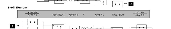
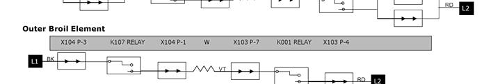
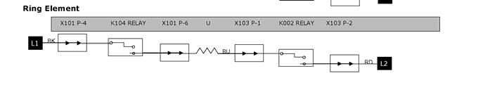
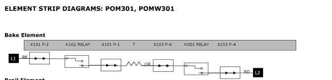
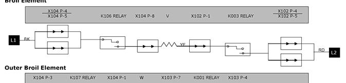
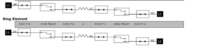
20 Figures Element strip diagrams Page 20 of 21
21 11 ADDITIONAL REFERENCES 11.1 QuickFinder For further information, please refer to the following documents on QuickFinder: Wiring Diagram (Built-in Oven Service Guide) Installation Instructions Use and Care Manual MCES/MCEB Convection Microwave Use and Care Manual MCES/MCEB Convection Microwave Installation Instructions MCES/MCEB Convection Microwave Service Manual WD27/WD30 Traditional Warming Drawer Use and Care Manual Exploded views, parts lists, and related service and parts notes are also available on QuickFinder. NOTICE Not all service parts are shown on the QuickFinder exploded views; review the parts list for additional information Technical Support To reach Thermador technical support, call the toll free TechLine at Technicians are available to assist you Monday Friday, between the hours of 5am and 5pm, Pacific Time ARA EN A BSH Home Appliances Corporation 5551 McFadden Avenue Huntington Beach, CA September 2007 Page 21 of 21
C Series Oven Training Program
 C Series Oven Training Program Features and Operation Model Numbers Warranty Component Description and Access Error Codes How the Oven Works Service Tips Features and Operation All C series ovens have
NOTICE . SAFE SERVICING PRACTICES. Electric Wall Oven with Electronic Oven Control
 SERVICE DATA SHEET 318047418 (0504) Rev. A Electric Wall Oven with Electronic Oven Control NOTICE This service data sheet is intended for use by persons having electrical and mechanical training and a
Products documentation (REVISION DATE: 03/10/2011) OMFP6010 (60cm PIROLITIC OVEN)
 OMFP6010 (60cm PIROLITIC OVEN)") Products documentation (REVISION DATE: 03/10/2011) OMFP6010 (60cm PIROLITIC OVEN) Ovens Service Manual Models OMFP6010 CONTENTS This document has been published to be used for service only. The contents
Products documentation (REVISION DATE: 03/10/2011) OMFP6010 (60cm PIROLITIC OVEN) Ovens Service Manual Models OMFP6010 CONTENTS This document has been published to be used for service only. The contents
! WARNING To avoid risk of electrical shock, personal injury or death; disconnect power to range before servicing, unless testing requires power.
 Technical Information Electric Slide-In Range JES8850BC* JES9900BC* JES9860BC* Due to possibility of personal injury or property damage, always contact an authorized technician for servicing or repair
Dacor Technical Service
 Attention: This manual is just a section from the complete Wall Oven Service Manual. If you find that you require the complete service manual, which includes exploded views and parts, use and care information
! WARNING To avoid risk of electrical shock, personal injury or death; disconnect power to range before servicing, unless testing requires power.
 Technical Information Electric Downdraft Slide-In Range JES9800BA* JES9900BA* Due to possibility of personal injury or property damage, always contact an authorized technician for servicing or repair of
BOSCH. i!i_!!i_!_i_iii!i_!i!iii!_i_i_!ii!_!_!_!_!_!i_ji_i_!!!!!_!_!!_!iii!i_i_. Built-in Ovens
 Built-in Ovens BOSCH Models: HBL33, HBN33, HBL34, HBN34, HBL35, HBN35, HBL54, HBN54, HBL56, HBN56, HBL57, HBL8550, HBL8650, HBL8750 i!i_!!i_!_i_iii!i_!i!iii!_i_i_!ii!_!_!_!_!_!i_ji_i_!!!!!_!_!!_!iii!i_i_...,,_,,,_,,
! WARNING To avoid risk of electrical shock, personal injury or death; disconnect power to range before servicing, unless testing requires power.
 Technical Information Electric Slide-In Range JES9750BA* JES9860BA* Due to possibility of personal injury or property damage, always contact an authorized technician for servicing or repair of this unit.
Technical Seminar HL-BD82S. Electric Built-In Oven. Panasonic Canada 2013
 Technical Seminar Electric Built-In Oven HL-BD82S Panasonic Canada 2013 Agenda 1. Specification & Operation 2. Parts name 3. Circuit diagram 4. Troubleshooting 5. Disassembly & Assembly FEATURES Specification
Service Manual. Thermador Built-In Oven. for. Models: SMW272 B, SMW272S, SMW272W, SMW272P STOP TIME SELF CLEAN OVEN LIGHT COOK TIME BAKE OFF
 TIMER 1 TIMER 2 CLOCK BAKE BROIL CONVECTION OFF CONVECTIO ROAST SENSOR REHEAT POWER LEVEL SENSOR COOK POP CORN 1 2 3 4 5 6 7 8 9 TIMER 0 CLOCK MORE /LESS SERVING /WEIGHT STOP/RESET QUICK MIN KEEP WARM
! WARNING To avoid risk of electrical shock, personal injury or death; disconnect power to oven before servicing, unless testing requires power.
 Technical Information Electric Slide-In Range JES8850ACB/S/W JES9750ACB/W JES9800ACB/S/W JES9860ACB/S/W Due to possibility of personal injury or property damage, always contact an authorized technician
TABLE OF CONTENTS ELECTRIC BUILT-IN OVEN. Model No. HL-BD82S. Canada
 Order Number MENO121101CE ELECTRIC BUILT-IN OVEN Model No. HL-BD82S Canada TABLE OF CONTENTS PAGE 1 Safety Precautions----------------------------------------------- 2 2 Service Navigation -----------------------------------------------
Technical Service Guide
 GE Consumer & Industrial Technical Service Guide April 2006 Monogram 30-in. Single and Double Convection Wall Ovens ZET1PL1SS ZET1SL1SS ZET2PL1SS ZET2SL1SS 31-9142 GE Appliances General Electric Company
MASTERPIECE /THERMADOR PROFESSIONAL SERIES BUILT-IN OVEN
 MASTERPIECE /THERMADOR PROFESSIONAL SERIES BUILT-IN OVEN Built-in oven Four encastré Horno empotrado Table of Contents... 4 Table de Matières...19 Contenido...35 Models/Modèle/Modelo ME301JP ME301JS ME302JP
30" BUILT-IN COMBINATION MICROWAVE WALL OVEN Models:
 PARTS LIST for 30" BUILT-IN COMBINATION MICROWAVE WALL OVEN Models: KEMS309BBL00 (Black) KEMS309BWH00 (White) KEMS309BSS00 (Stainless) KEMS309BSP00 (Pro-Style) FOR CUSTOMER SATISFACTION ALWAYS USE FACTORY
30 & 36 FLUSH-MOUNT GAS COOKTOPS
 CONSUMER SERVICES TECHNICAL EDUCATION GROUP PRESENTS KR-37 30 & 36 FLUSH-MOUNT GAS COOKTOPS Model GLS3064R S Model GLS3665R S JOB AID Part No. 8178526 FORWARD This Whirlpool Job Aid, 30 & 36 Flush-Mount
OVEN PARTS For Models: KEMS378SBL05, KEMS378SWH05, KEMS378SSS05 (Black) (White) (Stainless)
 (White) (Stainless)") OVEN PARTS 27" BUILT IN ELECTRIC COMBO OVEN THERMAL CONVECTION 11 11 Litho in U.S.A. (rek) (eeb) 1 Part No. Rev. B OVEN PARTS 1 Literature Parts Installation Instructions 8304337 English W10075750 Bi lingual
OVEN PARTS 27" BUILT IN ELECTRIC COMBO OVEN THERMAL CONVECTION 11 11 Litho in U.S.A. (rek) (eeb) 1 Part No. Rev. B OVEN PARTS 1 Literature Parts Installation Instructions 8304337 English W10075750 Bi lingual
30" BUILT-IN ELECTRIC COMBINATION MICROWAVE WALL OVEN MODELS: WOC54EC0AB03 (Black) WOC54EC0AW03 (White) WOC54EC0AS03 (Stainless)
 WOC54EC0AW03 (White) WOC54EC0AS03 (Stainless)") 30" BUILT-IN ELECTRIC COMBINATION MICROWAVE WALL OVEN MODELS: WOC54EC0AB03 (Black) WOC54EC0AW03 (White) WOC54EC0AS03 (Stainless) 12/04/2015 2015 Whirlpool Corporation Part W10850853 Rev. A CONTROL PANEL
30" BUILT-IN ELECTRIC COMBINATION MICROWAVE WALL OVEN MODELS: WOC54EC0AB03 (Black) WOC54EC0AW03 (White) WOC54EC0AS03 (Stainless) 12/04/2015 2015 Whirlpool Corporation Part W10850853 Rev. A CONTROL PANEL
WARNING FOR SERVICE TECHNICIAN S USE ONLY
 ech Sheet Do not discard ANING Electrical Shock Hazard Disconnect power before servicing. eplace all parts and panels before operating. Failure to do so can result in death or electrical shock. Software
OVEN PARTS For Models:YKEMC308KM02 (STAINLESS STEEL)
") OVEN PARTS 30" BUILT IN ELECTRIC DOUBLE OVEN THERMAL CONVECTION LOWER MICROWAVE CONVECTION UPPER 7 05 Litho in U.S.A. (cre) 1 Part No. Rev.A 1 Literature Parts 8300650 Installation Instructions Use & Care
OVEN PARTS 30" BUILT IN ELECTRIC DOUBLE OVEN THERMAL CONVECTION LOWER MICROWAVE CONVECTION UPPER 7 05 Litho in U.S.A. (cre) 1 Part No. Rev.A 1 Literature Parts 8300650 Installation Instructions Use & Care
OVEN PARTS For Models: KEMC308KBL04, KEMC308KWH04, KEMC308KBT04, KEMC308KSS04 (Black) (White) (Biscuit) (Stainless Steel)
 (White) (Biscuit) (Stainless Steel)") OVEN PARTS 30" BUILT IN ELECTRIC DOUBLE OVEN THERMAL CONVECTION LOWER MICROWAVE CONVECTION UPPER 3 08 Litho in U.S.A. (dmm) 1 Part No. OVEN PARTS 1 Literature Parts 8300653 Installation Instructions 8304066
OVEN PARTS 30" BUILT IN ELECTRIC DOUBLE OVEN THERMAL CONVECTION LOWER MICROWAVE CONVECTION UPPER 3 08 Litho in U.S.A. (dmm) 1 Part No. OVEN PARTS 1 Literature Parts 8300653 Installation Instructions 8304066
OVEN PARTS For Models:WOC95EC0AB00, WOC95EC0AW00, WOC95EC0AS00, WOC95EC0AE00, WOC95EC0AH00 (Black) (White) (Stainless) (Black Ice) (White Ice)
 (White) (Stainless) (Black Ice) (White Ice)") OVEN PARTS 30" BUILT IN ELECTRIC COMBINATION MICROWAVE CONVECTION WALL OVEN 2 12 Litho in U.S.A. (rek) (psw) 1 Part No. Rev. A OVEN PARTS 1 Literature Parts W10351241 Installation Instructions Use & Care
OVEN PARTS 30" BUILT IN ELECTRIC COMBINATION MICROWAVE CONVECTION WALL OVEN 2 12 Litho in U.S.A. (rek) (psw) 1 Part No. Rev. A OVEN PARTS 1 Literature Parts W10351241 Installation Instructions Use & Care
OVEN PARTS. For Models: JMW3430WB01, JMW3430WS01, JMW3430WR01, JMW3430WP01 (Black) (Stainless) (Oil Bronze) (Pro Style) Part No. W Rev.
 (Stainless) (Oil Bronze) (Pro Style) Part No. W Rev.") OVEN PARTS 30" MICROWAVE / WALL OVEN COMBO 4 12 Litho in U.S.A. (rek)(bay) 1 Part No. Rev. D OVEN PARTS 1 Literature Parts Installation Instructions W10221384 English W10075750 Bi Lingual Owners Manual
OVEN PARTS 30" MICROWAVE / WALL OVEN COMBO 4 12 Litho in U.S.A. (rek)(bay) 1 Part No. Rev. D OVEN PARTS 1 Literature Parts Installation Instructions W10221384 English W10075750 Bi Lingual Owners Manual
OVEN PARTS. For Models: JMW2430WB02, JMW2430WS02, JMW2430WR02, JMW2430WW02, JMW2430WP02 (Black) (Stainless) (Oil Bronze) (White) (Pro Style)
 (Stainless) (Oil Bronze) (White) (Pro Style)") OVEN PARTS 30" MICROWAVE / WALL OVEN COMBO 3 12 Litho in U.S.A. (rek) (psw) 1 Part No. Rev. A OVEN PARTS 1 Literature Parts Installation Instructions W10221384 English W10075750 Bi Lingual Owners Manual
OVEN PARTS 30" MICROWAVE / WALL OVEN COMBO 3 12 Litho in U.S.A. (rek) (psw) 1 Part No. Rev. A OVEN PARTS 1 Literature Parts Installation Instructions W10221384 English W10075750 Bi Lingual Owners Manual
30" BUILT-IN ELECTRIC COMBINATION MICROWAVE WALL OVEN MODELS: WOC54EC0AB01 (Black) WOC54EC0AW01 (White) WOC54EC0AS01 (Stainless)
 WOC54EC0AW01 (White) WOC54EC0AS01 (Stainless)") 30" BUILT-IN ELECTRIC COMBINATION MICROWAVE WALL OVEN MODELS: WOC54EC0AB01 (Black) WOC54EC0AW01 (White) WOC54EC0AS01 (Stainless) 03/21/2014 2014 Whirlpool Corporation Part W10696649 Rev. A OVEN PARTS 03/21/2014
30" BUILT-IN ELECTRIC COMBINATION MICROWAVE WALL OVEN MODELS: WOC54EC0AB01 (Black) WOC54EC0AW01 (White) WOC54EC0AS01 (Stainless) 03/21/2014 2014 Whirlpool Corporation Part W10696649 Rev. A OVEN PARTS 03/21/2014
TECH SHEET DO NOT DISCARD PAGE 1. If unsuccessful entry into diagnostic mode, actions can be taken for specific indications:
 TECH SHEET DO NOT DISCARD PAGE 1 WARNING Electrical Shock Hazard Disconnect power before servicing. Replace all parts and panels before operating. Failure to do so can result in death or electrical shock.
OVEN PARTS For Models: JMW2427WB00, JMW2427WS00, JMW2427WW00 (Black) (Stainless) (White)
 (Stainless) (White)") OVEN PARTS 27" MICROWAVE / WALL OVEN COMBO 2 12 Litho in U.S.A. (DAF)(bay) 1 Part No. Rev. E OVEN PARTS 1 Literature Parts Installation Instructions W10221384 English W10075750 Bi Lingual Owners Manual
OVEN PARTS 27" MICROWAVE / WALL OVEN COMBO 2 12 Litho in U.S.A. (DAF)(bay) 1 Part No. Rev. E OVEN PARTS 1 Literature Parts Installation Instructions W10221384 English W10075750 Bi Lingual Owners Manual
OVEN PARTS For Models:YKEMC308KM0 (STAINLESS STEEL)
") OVEN PARTS 30" BUILT IN ELECTRIC DOUBLE OVEN THERMAL CONVECTION LOWER MICROWAVE CONVECTION UPPER 5 03 Litho in U.S.A. (cre) 1 Part No. NOTE: The screws and nuts required to attach a part are listed immediately
OVEN PARTS 30" BUILT IN ELECTRIC DOUBLE OVEN THERMAL CONVECTION LOWER MICROWAVE CONVECTION UPPER 5 03 Litho in U.S.A. (cre) 1 Part No. NOTE: The screws and nuts required to attach a part are listed immediately
ImPress IRONING STATION
 CONSUMER SERVICES TECHNICAL EDUCATION GROUP PRESENTS L-73 ImPress IRONING STATION Model LFB2611L JOB AID Part No. 8178203 FORWARD This Whirlpool Job Aid, ImPress Ironing Station, (Part No. 8178203), provides
ValkyrieTM. Instruction Manual. Includes our new CoolTouch TM 6 Speed DC Control System Looks permanent, but goes wherever you go! U.S.
 ValkyrieTM A Kichler Décor ceiling fan Designed to coordinate with a popular Kichler Lighting collection. Includes our new CoolTouch TM 6 Speed DC Control System Looks permanent, but goes wherever you
GE JB400 Steam Clean Range. Range Models: JB400DP1WW JB400DP1BB JB400SPSS
 GE JB400 Steam Clean Range Range Models: JB400DP1WW JB400DP1BB JB400SPSS IMPORTANT SAFETY NOTICE The information in this presentation is intended for use by individuals possessing adequate backgrounds
VIKING RANGE CORPORATION, P.O. DRAWER 956, GREENWOOD,MS USA
 VIKING RANGE CORPORATION, P.O. DRAWER 956, GREENWOOD,MS 38930 USA TABLE OF CONTENTS VDSC ( Dual fuel ) / VESC (Electric) RANGES / VERT (Rangetop) COMPONENTS AND FUNCTIONAL PARTS: Control / Timer ------------------------------------------------------------------------------------------------------
11 05 litho in U.S.A. (cre) 1. Part No
 1. Part No") OVEN PARTS 27" BUILT IN ELECTRIC DOUBLE OVEN THERMAL CONVECTION LOWER MICROWAVE CONVECTION UPPER 11 05 litho in U.S.A. (cre) 1 Part No. OVEN PARTS 1 Literature Parts 8300653 Installation Instructions 8302973
OVEN PARTS 27" BUILT IN ELECTRIC DOUBLE OVEN THERMAL CONVECTION LOWER MICROWAVE CONVECTION UPPER 11 05 litho in U.S.A. (cre) 1 Part No. OVEN PARTS 1 Literature Parts 8300653 Installation Instructions 8302973
Installation Instructions Wall Ovens
 Installation Instructions Wall Ovens TESTED IN ACCORDANCE WITH THE LATEST EDITION OF UL858 STANDARD FOR HOUSEHOLD ELECTRIC COOKING APPLIANCES. IMPORTANT 1. Before beginning installation, please thoroughly
30 Electric Self Cleaning Double Wall Oven
 30 Self Clean Double Wall Oven Stainless steel Electronic controls with intuitive and easy access to oven s cooking functions Pyrolytic Self Cleaning with auto door latch 12 Cooking Functions including
SERVICE MANUAL COOKERS
 SERVICE MANUAL COOKERS Electrolux Distriparts Muggenhofer Straße 135 D-90429 Nürnberg Germany Publ.-Nr.: 599 522 770 685 EN Ovens Compact Range Steam Fax +49 (0)911 323 1022 DGS-TDS-N Edition: 03.08 Table
SERVICE DATA SHEET (9704) Rev. D
 Rev. D") SERVICE DATA SHEET 318047401 (9704) Rev. D Electric Wall Ovens with Electronic Oven Control (ERC III - 318010700 & 318010900) NOTICE This service data sheet is intended for use by persons having electrical
SERVICE DATA SHEET 318047401 (9704) Rev. D Electric Wall Ovens with Electronic Oven Control (ERC III - 318010700 & 318010900) NOTICE This service data sheet is intended for use by persons having electrical
NN-A750WB NN-A720MB NN-A770SB 27L WHITE SILVER STAINLESS United Kingdom
 Order Number MOP00080014C2 Microwave Oven NN-A750WB NN-A720MB NN-A770SB 27L WHITE SILVER STAINLESS United Kingdom Specification Timer 99 Minutes 99 Seconds Power Source Power Requirements 240VAC Single
OVEN PARTS For Models:KEMC377KBL05, KEMC377KWH05, KEMC377KBT05, KEMC377KSS05 (Black) (White) (Biscuit) (S.Steel)
 (White) (Biscuit) (S.Steel)") OVEN PARTS 27" BUILT IN ELECTRIC DOUBLE OVEN THERMAL CONVECTION LOWER CRISPWAVE MICROWAVE UPPER 9 06 Litho in U.S.A. (cre) 1 Part No. Rev. A OVEN PARTS 1 Literature Parts 8300653 Installation Instructions
OVEN PARTS 27" BUILT IN ELECTRIC DOUBLE OVEN THERMAL CONVECTION LOWER CRISPWAVE MICROWAVE UPPER 9 06 Litho in U.S.A. (cre) 1 Part No. Rev. A OVEN PARTS 1 Literature Parts 8300653 Installation Instructions
OVEN PARTS For Models:KEMS308SBL05, KEMS308SWH05, KEMS308SSS05 (Black) (White) (Stainless)
 (White) (Stainless)") OVEN PARTS 30" BUILT IN ELECTRIC COMBO OVEN THERMAL CONVECTION 2 12 Litho in U.S.A. (BMN) (psw) 1 Part No. W10414013 Rev. B OVEN PARTS 1 Literature Parts 8304337 Installation Instructions Use & Care Guide
OVEN PARTS 30" BUILT IN ELECTRIC COMBO OVEN THERMAL CONVECTION 2 12 Litho in U.S.A. (BMN) (psw) 1 Part No. W10414013 Rev. B OVEN PARTS 1 Literature Parts 8304337 Installation Instructions Use & Care Guide
! WARNING To avoid risk of electrical shock, personal injury or death; disconnect power to oven before servicing, unless testing requires it.
 Electric Wall Oven Technical Information JJW8627DD*, JJW8630DD*, JJW9627DD*, JJW9630DD*, JJW9827DD*, JJW9830DD* Refer to Service Manual 16022506 for detailed installation, operating, testing, troubleshooting,
54" Skye. Instruction Manual Customer Service :30 AM to 5:00 PM EST, Monday - Friday A Kichler Decor ceiling fan
 54" Skye TM 300167 A Kichler Decor ceiling fan Includes wall mount control system Kichler Lighting 7711 East Pleasant Valley Road P.O. Box 318010 Cleveland, Ohio 44131-8010 Instruction Manual Customer
! WARNING To avoid risk of electrical shock, personal injury or death; disconnect power to oven before servicing, unless testing requires power.
 Electric Wall Oven Technical Information JJW8527DDB/W/Q/S JJW9527DDB/W/S JJW8530DDB/W/Q/S JJW9530DDB/W/S Refer to Service Manual 16022506 for detailed installation, operating, testing, troubleshooting,
Service. Manual. Built-in Dishwasher. Preferred Service. VDB450 DFB450 (Before 5/26/2010)
") Service Preferred Service Manual This manual is to be used by qualified appliance technicians only. Viking does not assume any responsibility for property damage or personal injury for improper service
Service Preferred Service Manual This manual is to be used by qualified appliance technicians only. Viking does not assume any responsibility for property damage or personal injury for improper service
TECHNICAL INFORMATION Touchtronic Clothes Dryers
 TECHNICAL INFORMATION Touchtronic Clothes Dryers Includes: T1302, T1303, T1322, T1329ci T1403 & T1405 2004 Miele This page intentionally left blank. Table of Contents GENERAL INFORMATION A. Warning and
WHIRLPOOL AUSTRALASIA CONSUMER SERVICES
 December 2001 WHIRLPOOL AUSTRALASIA CONSUMER SERVICES SERVICE MANUAL MICROWAVE OVEN Version 8538 231 53291 Copyright 2001 Whirlpool (Australia) Pty. Limited All rights strictly reserved. Reproduction or
SERVICE MANUAL VC3ED FULL SIZE ELECTRIC CONVECTION OVEN - NOTICE -
 SERVICE MANUAL VC3ED FULL SIZE ELECTRIC CONVECTION OVEN VC3ED ML-137013 - NOTICE - This Manual is prepared for the use of trained Vulcan Service Technicians and should not be used by those not properly
VIKING RANGE CORPORATION, P. O. DRAWER 956, GREENWOOD, MS USA
 VIKING RANGE CORPORATION, P. O. DRAWER 956, GREENWOOD, MS.38930 USA TABLE OF CONTENTS VDSC / DUAL FUEL SELF-CLEAN RANGE VESO SINGLE ELECTRIC SELF-CLEAN WALL OVEN VEDO DOUBLE ELECTRIC SELF-CLEAN WALL OVEN
FOR SERVICE TECHNICIAN S USE ONLY
 Tech Sheet FOR SERVICE TECHNICIAN S USE ONLY Do not discard DANGER WARNING Electrical Shock Hazard Only authorized technicians should perform diagnostic voltage measurements. After performing voltage measurements,
60" Lyndon Patio. Instruction Manual Customer Service :30 AM to 5:00 PM EST, Monday - Friday A Kichler Decor ceiling fan
 60" Lyndon Patio TM 310140 A Kichler Decor ceiling fan Includes wall mount control system Kichler Lighting 7711 East Pleasant Valley Road P.O. Box 318010 Cleveland, Ohio 44131-8010 Instruction Manual Customer
SERVICE MANUAL WASHING MACHINE MODEL: WM3431H*/WM3434H* WD-14312RD/WD-14316RD CAUTION
 Website: http://www.lgeservice.com [For U.S.A] www.lg.ca [For CANADA] E-mail: http://www.lgeservice.com/techsup.html WASHING MACHINE SERVICE MANUAL! CAUTION READ THIS MANUAL CAREFULLY TO DIAGSE PROBLEMS
Please read this manual completely before attempting to install, operate or service this equipment.
 Service Manual POWER OVEN OFF COOL DOWN COOK LIGHT OFF OVEN READY TEMPERATURE GAS CONVECTION OVEN TIME GAS SHUTOFF ON OFF MODELS 6/13 THE OVEN E SERIES Please read this manual completely before attempting
OPERATIONS MAINTENANCE MANUAL
 OPERATIONS MAINTENANCE MANUAL COOK & HOLD OVEN SYSTEMS WITTCO MODEL NUMBERS 1300-AD-SS 1300-AD-SS-SPLIT LIMITED WARRANTY Wittco warrants the Products that it manufactures to be free from defects in materials
Instruction Manual for Electric Ovens OO757X OO986X
 Instruction Manual for Electric Ovens OO757X OO986X 1 2 DEAR CUSTOMER, We thank you and congratulate you on your choice. This new carefully designed product, manufactured with the highest quality materials,
Decorative Low Profile Integrated Kit
 Decorative Low Profile Integrated Kit Installation Manual Models 99050, 99051,99052, 99053, 99054, 99055 Compatible with: 2xxxx Types A - Z 51000-58999 fan series 59500-59999 fan series Select Casablanca
WALL OVEN SELLING GUIDE
 THERMADOR WALL OVEN SELLING GUIDE MASTERPIECE SERIES PROFESSIONAL SERIES 2 CONTENTS INTRODUCTION TEST PROCEDURES TEST RESULTS FACTS ABOUT THE COMPETITION AT-A-GLANCE COMPETITIVE CHART THE SECRETS OF THERMADOR
! WARNING To avoid risk of electrical shock, personal injury or death; disconnect power to dryer before servicing, unless testing requires power.
 27 Domestic Dryer Technical Information MDE6700A*, MDG6700A* Due to possibility of personal injury or property damage, always contact an authorized technician for servicing or repair of this unit. Refer
KAC - 57 TECHNICAL EDUCATION JOB AID W & 30 Built-In Single and Double Wall Ovens. Multimedia Enhanced
 KAC - 57 Multimedia Enhanced TECHNICAL EDUCATION 7 & 30 Built-In Single and Double Wall Ovens JOB AID W08075 FORWARD This KitchenAid Job Aid, 7 & 30 Single and Double Wall Ovens (Part No. W08075), provides
STEAMPRO. Steam Generator Troubleshooting and Service Guide
 STEAMPRO Steam Generator Troubleshooting and Service Guide TABLE OF CONTENTS Page PREFACE... 1 I. STEAMPRO STEAM GENERATOR SYSTEM...2 II. PLUMBING AND ELECTRICAL...3-4 III. SYSTEM OVERVIEW... 5-10 IV.
FerronTM. Instruction Manual A Kichler Decor ceiling fan
 Includes our new CoolTouch TM 6 Speed DC Control System Looks permanent, but goes wherever you go! U.S. Patent Pending 300160 A Kichler Decor ceiling fan HIGH EFFICIENCY DC MOTOR FerronTM Kichler Lighting
TECHNICAL INFORMATION MasterChef Ovens
 TECHNICAL INFORMATION MasterChef Ovens 2011 Miele USA Table of Contents 1.0 Construction and Design... 6 1.1 Summary of Model Numbers... 6 1.1.1 H 39x MasterChef Ovens... 6 1.1.2 H 39x MasterChef Warming
Installation Instructions
 Installation Instructions Self-Cleaning Radiant Electric Drop-In Range JDP47, JD968, JD900 If you have questions, call 1.800.GE.CARES or visit our website at: ge.com Before You Begin Read these instructions
DryAire DRYING CABINET
 CONSUMER SERVICES TECHNICAL EDUCATION GROUP PRESENTS L-72 DryAire DRYING CABINET Model LMA1053L JOB AID Part No. 8178202 FORWARD This Whirlpool Job Aid, DryAire Drying Cabinet, (Part No. 8178202), provides
Innes. Instruction Manual A Kichler Decor ceiling fan. Includes our new TM
 Innes 300130 A Kichler Decor ceiling fan Includes our new CoolTouch Control System Looks permanent, but goes wherever you go! U.S. Patent Pending Kichler Lighting 7711 East Pleasant Valley Road P.O. Box
2 PREPARE THE OPENING
 Installation Instructions 27 & 30 Electric Built-In Wall Ovens Questions? Call 1.800.GE.CARES (1.800.432.2737) or visit www.geappliances.com In Canada, call 1.800.561.3344 or visit www.geappliances.ca
122 MODEL SHOWN: PODMW301J TRIPLE COMBINATION BUILT-IN OVEN
 122 MODEL SHOWN: PODMW301J TRIPLE COMBINATION BUILT-IN OVEN BUILT-IN OVENS PROFESSIONAL & MASTERPIECE SERIES An array of industry-leading features and exclusives make Thermador Built-In Ovens the only
Installation Instructions
 Installation Instructions Electric Drop-In Range JDS28, JDP39 Questions? Call 800.GE.CARES (800.432.2737) or Visit our Website at: ge.com BEFORE YOU BEGIN Read these instructions carefully and completely.
3500 SERIES CONVECTION STEAM COOKER PARTS AND SERVICE MANUAL
 3500 SERIES CONVECTION STEAM COOKER PARTS AND SERVICE MANUAL EFFECTIVE JULY 30, 2014 Superseding All Previous Parts Lists. The Company reserves the right to make substitution in the event that items specified
ST. KITTS CEILING FAN
 ITEM #0845047 ST. KITTS CEILING FAN MODEL #40829 Questions, problems or missing parts? Before returning this item to your retailer, call our customer service department at 1-800-643-0067, Monday - Thursday,
S Series Ovens. Thermador Field Service
 S Series Ovens Thermador Field Service Introduction Features and Operation Model Numbers Warranty Component Description Error Codes How The Oven Works Hints & Tips Features Field Sensor touch control Digi-pad
Installation Guide. For Models: E-MLV36BNK4LK1 E-MLV36ESP4LK1 E-MLV36WW4LK1 READ THESE INSTRUCTIONS AND AND SAVE THEM FOR FUTURE USE
 READ THESE INSTRUCTIONS AND AND SAVE THEM FOR FUTURE USE Federal regulations require ceiling fans with light kits manufactured or imported after January 1, 2009, to limit total wattage consumed by the
OVEN PARTS For Models:YKEHV309PS01, YKEHV309PM01 (Stainless Steel) (Meteorite)
 (Meteorite)") OVEN PARTS 30" BUILT IN ELECTRIC DOUBLE OVEN THERMAL CONVECTION LOWER MICROWAVE CONVECTION UPPER 11 05 Litho in U.S.A. (cre) 1 Part No. OVEN PARTS 1 Literature Parts 8300650 Installation Instructions 8304065
OVEN PARTS 30" BUILT IN ELECTRIC DOUBLE OVEN THERMAL CONVECTION LOWER MICROWAVE CONVECTION UPPER 11 05 Litho in U.S.A. (cre) 1 Part No. OVEN PARTS 1 Literature Parts 8300650 Installation Instructions 8304065
52 StarkkTM. Instruction Manual. A Kichler Select ceiling fan
 52 StarkkTM A Kichler Select ceiling fan Kichler Lighting 7711 East Pleasant Valley Road P.O. Box 318010 Cleveland, Ohio 44131-8010 Customer Service 866.558.5706 8:30 AM to 5:00 PM EST, Monday - Friday
Water Distiller Service Manual
 Water Distiller Service Manual Water Distiller Service Manual L70478WT 2008 Regal Ware, Inc. Table of Contents RECOMMENDED TOOLS... 2 GENERAL INSPECTION...3 BOILING CHAMBER TROUBLESHOOTING & REPAIRS Description...
Installation Instructions. Discovery Wall Oven. EO, MOH and MOV Series. Part No Rev. M
 Discovery Wall Oven EO, MOH and MOV Series Installation Instructions Part No. 65433 Rev. M All specifications are subject to change without notice. Dacor assumes no liability for changes to specifications.
COOKTOP, BURNER AND GRATE PARTS For Model: JGRP548WP00 (Stainless)
") COOKTOP, BURNER AND GRATE PARTS 48" Stainless Commercial Style Range 8 10 Litho in U.S.A. (amd) (psw) 1 Part No. Rev. B COOKTOP, BURNER AND GRATE PARTS 1 Literature Parts Tech Sheet W10323236 English W10323237
COOKTOP, BURNER AND GRATE PARTS 48" Stainless Commercial Style Range 8 10 Litho in U.S.A. (amd) (psw) 1 Part No. Rev. B COOKTOP, BURNER AND GRATE PARTS 1 Literature Parts Tech Sheet W10323236 English W10323237
Safety, Installation, and Operation Manual
 Automatic Steam Humidifier Control Safety, Installation, and Operation Manual READ COMPLETE INSTALLATION INSTRUCTIONS BEFORE STARTING. WARNING This product must be installed by a qualified heating and
1998 DISHWASHERS Servicing and Troubleshooting
 CONSUMER SERVICES TECHNICAL EDUCATION GROUP PRESENTS KD-10 1998 DISHWASHERS Servicing and Troubleshooting MODELS DU800DWG DU801DWG DU805DWG DU810DWG DP840DWG DU840DWG DU850DWG DU890DWG DU910PFG DP920PFG
RANGE STUDY COURSE UNDERSTANDING RANGE: MECHANICAL COMPONENTS. Module 3 LIT Rev. C
 RANGE STUDY COURSE UNDERSTANDING RANGE: MECHANICAL COMPONENTS Module 3 LIT 4314426 Rev. C WHIRLPOOL CORPORATION does not assume any responsibility or any liability in connection with the use of this manual.
Full Size Canister Service Manual Riccar Models 1700 / 1800 Power Nozzles RPB-100 / RPB-220 / RPB-224 / RPB-250
 Full Size Canister Service Manual Riccar Models 1700 / 1800 Power Nozzles RPB-100 / RPB-220 / RPB-224 / RPB-250 Table of Contents I. General Full Size Canister Issues...2 A. Full Bag Indicator...2 1. General
P MODEL AIR CONDITIONER
 CONSUMER SERVICES TECHNICAL EDUCATION GROUP PRESENTS R-94 P MODEL AIR CONDITIONER JOB AID Part No. 8178039 FORWARD This Whirlpool Job Aid, P Model Air Conditioner (Part No. 8178039), provides the technician
WASHING MACHINE SERVICE MANUAL CAUTION READ THIS MANUAL CAREFULLY TO DIAGNOSE PROBLEMS CORRECTLY BEFORE SERVICING THE UNIT.
 WASHING MACHINE SERVICE MANUAL CAUTION READ THIS MANUAL CAREFULLY TO DIAGSE PROBLEMS CORRECTLY BEFORE SERVICING THE UNIT. MODEL : WM2240C* Jul. 2010 PRINTED IN KOREA P/No. : MFL30599179 CONTENTS 1.SPECIFICATIONS...
Wall Oven. Service Parts Manual SO30 - DO30 - SO36. WOLF APPLIANCE COMPANY, LLC 2005 ALL RIGHTS RESERVED JOB AID # (Revision A - June 2005)
") Wall Oven Service Parts Manual SO0 - DO0 - SO6 WOLF APPLIANCE COMPANY, LLC 2005 ALL RIGHTS RESERVED JOB AID # 80662 (Revision A - June 2005) Wall Ovens Parts List with Exploded Views INTRODUCTION This
Wall Oven Service Parts Manual SO0 - DO0 - SO6 WOLF APPLIANCE COMPANY, LLC 2005 ALL RIGHTS RESERVED JOB AID # 80662 (Revision A - June 2005) Wall Ovens Parts List with Exploded Views INTRODUCTION This
Instruction manual for pyrolytic oven
 Instruction manual for pyrolytic oven Model code: C2480 Contact Caple on 0844 800 3830 or for spare parts www.4caple.co.uk CONTENTS GB Safety instructions... 2 Installing the oven... 3 Electrical details...3
LaceyTM. Instruction Manual. Includes our new CoolTouch TM 6 Speed DC Control System Looks permanent, but goes wherever you go! U.S.
 LaceyTM A Kichler Décor ceiling fan Designed to coordinate with a popular Kichler Lighting collection. Includes our new CoolTouch TM 6 Speed DC Control System Looks permanent, but goes wherever you go!
Installation Instructions. Discovery Wall Oven. Preliminary - For Review Only No Scheduled Release Date. For use with models EO, MO and PO
 Discovery Wall Oven For use with models EO, MO and PO Installation Instructions Preliminary - For Review Only No Scheduled Release Date Part No. 65433 Rev. H All specifications are subject to change without
42 Kevlar. Instruction Manual. Kichler Lighting 7711 East Pleasant Valley Road P.O. Box Cleveland, Ohio
 42 Kevlar Kichler Lighting 7711 East Pleasant Valley Road P.O. Box 318010 Cleveland, Ohio 44131-8010 Customer Service 866.558.5706 8:30 AM to 5:00 PM EST, Monday - Friday Instruction Manual 1 1. SAFETY
DFG-100 XCEL SERIES GAS CONVECTION OVEN REPLACEMENT PARTS LIST
 DFG-00 XCEL SERIES GAS CONVECTION OVEN REPLACEMENT PARTS LIST EFFECTIVE JANUARY, 0 Superseding All Previous Parts Lists. The Company reserves the right to make substitution in the event that items specified
DOUBLE DISHDRAWER TM DISHWASHER
 DOUBLE DISHDRAWER TM DISHWASHER DD4DDFT & DD4DVT models INSTALLATION GUIDE US CA 5985 A 08.7 SAFETY AND WARNINGS! WARNING! Electrical Shock Hazard Before installing the dishwasher, remove the house fuse
Summer Breeze Heater Service Manual
 Summer Breeze Heater Service Manual RSBH RSBH-SB RSBHP Revision: 1.0 Issued: 12-18-2012 Table of Contents I. Basic Assembly and Operation A. Safety Instructions... 2 B. Grounding Instructions... 3 C.
USER MANUAL MODEL READ ALL INSTRUCTIONS BEFORE PROCEEDING. 5-2 Day Programmable Multi-Stage 2 Heat/1 Cool Heat Pump Digital Thermostat
 WARNING! Important Safety Information Builder MODEL 2200 Series 5-2 Day Programmable Multi-Stage 2 Heat/1 Cool Heat Pump Digital Thermostat USER MANUAL Compatible with low voltage multi stage heat/cool
Installing the Cisco ONS FAP-4 Fuse Alarm Panel
 Installing the Cisco ONS 15454-FAP-4 Fuse Alarm Panel Product Number: 15454-FAP-4= This document explains how to install, test, operate, and maintain the Cisco ONS 15454-FAP-4 fuse alarm panel. This document
52 STRATHMERE CEILING FAN
 52 STRATHMERE CEILING FAN Owner s Manual Models #20341 If a problem cannot be remedied or you are experiencing difficulty with installation, please contact the Service Department: 1-877-459-3267, 9 a.m.-
Henny Penny Island Warmer Model HMI-103 Model HMI-105 TECHNICAL MANUAL
 Henny Penny Island Warmer Model HMI-103 Model HMI-105 TECHNICAL MANUAL THIS PAGE INTENTIONALLY LEFT BLANK. Section TABLE OF CONTENTS Page Section 1. TROUBLESHOOTING... 1-1 1-1. Introduction... 1-1 1-2.
INSTRUCTIONMANUAL PYROLYTIC OVENS OO6A2X
 INSTRUCTIONMANUAL PYROLYTIC OVENS OO6A2X TABLE OF CONTENTS SAFETY INSTRUCTIONS... 2 INSTALLATION OF THE OVEN... 3 Electricals... 3 Connection to the electrical power mains... 5 INSTRUCTIONS FOR USE...
60" Tulle PatioTM. Instruction Manual. A Kichler Select ceiling fan
 60" Tulle PatioTM A Kichler Select ceiling fan cul Certified for Wet Location Kichler Lighting 7711 East Pleasant Valley Road P.O. Box 318010 Cleveland, Ohio 44131-8010 Customer Service 866.558.5706 8:30
30 Built-In Microwave Oven Combination IMPORTANT: Installer: Leave these instructions with the homeowner. Homeowner: Retain these instructions for
 30 Built-In Microwave Oven Combination IMPORTANT: Installer: Leave these instructions with the homeowner. Homeowner: Retain these instructions for future reference. 1 Read these instructions Before you
FOR SERVICE TECHNICIAN S USE ONLY
 F SERVICE TECHNICIAN S USE ONLY NOTE: This sheet contains important Technical Service Data. Tech Sheet Do Not Remove Or Destroy DANGER Electrical Shock Hazard Only authorized technicians should perform
52 DorsetTM. Instruction Manual. Basic Function Wall Control System Included. A Kichler Decor ceiling fan
 Basic Function Wall Control System Included 52 DorsetTM II A Kichler Decor ceiling fan Kichler Lighting 7711 East Pleasant Valley Road P.O. Box 318010 Cleveland, Ohio 44131-8010 Customer Service 866.558.5706
52 Lacey LED. Instruction Manual. 6 Speed DC Wall Control System
 6 Speed DC Wall Control System 52 Lacey LED HIGH EFFICIENCY DC MOTOR Kichler Lighting 7711 East Pleasant Valley Road P.O. Box 318010 Cleveland, Ohio 44131-8010 Customer Service 866.558.5706 8:30 AM to