Test Report issued under the responsibility of: Report Reference No... : Date of issue... : Total number of pages...
|
|
|
- Frank Norman
- 6 years ago
- Views:
Transcription

1 Test Report issued under the responsibility of: TEST REORT IEC/EN Safety of household and similar electrical appliances art 2-64: articular requirements for commercial electric kitchen machines Report Reference No.... : Date of issue... : Total number of pages CB/CCA Testing Laboratory... : Address... : Applicant s name... : Address... : UL International Italia S.r.l. Via delle Industrie Carugate - MI - (ITALY) KITCHENAID SMALL ALIANCES, DIV OF WHIRLOOL COR KITCHENAID ORTABLE ALIANCE TECH,ST JOSEH TECHNOLOGY CENTER,MD-0260 Test specification: Standard... : Test procedure... : Non-standard test method..: Test Report Form No.... : IEC :2002 (third Edition) with IEC :2001 (incl. Corr. 1:2002) + A1:2004 EN : A1:2002 with EN : A11:2004 CB / CCA IECEN60335_2_64A Test Report Form(s) Originator... : Electrosuisse Master TRF... : Dated Copyright 2007 IEC System for Conformity Testing and Certification of Electrical Equipment (IECEE), Geneva, Switzerland. All rights reserved. This publication may be reproduced in whole or in part for non-commercial purposes as long as the IECEE is acknowledged as copyright owner and source of the material. IECEE takes no responsibility for and will not assume liability for damages resulting from the reader's interpretation of the reproduced material due to its placement and context. If this Test Report Form is used by non-iecee members, the IECEE/IEC logo and the reference to the CB Scheme procedure shall be removed. This report is not valid as a CB Test Report unless signed by an approved CB Testing Laboratory and appended to a CB Test Certificate issued by an NCB in accordance with IECEE 02. If this Test Report Form is used by non-cca members, the CIG logo and the reference to the CCA rocedure shall be removed. This report is not valid as a CCA Test Report unless signed by an approved CCA Testing Laboratory and appended to a CCA Test Certificate issued by an NCB in accordance with CCA age 1 of 109
2 age 2 of 109 Report No Test item description... : Trade Mark... : Commercial Food Mixer (A registered Trademark of Whirlpool) Manufacturer... : KITCHENAID EUROA NIJVERHEIDSLAAN STROMBEEK-BEVER BRUSSELS - BELGIUM Model/Type reference... : Ratings... : Model 5KSM79XX+ Where XX = up to 2 alphanumeric characters, which represents the features, distributor code, and/or color + = May or may not be followed by five or more digit suffix codes to indicate change in aesthetics V~, 50/60 Hz, 325 W IX1 10min ON/15min OFF
 Associated CB Laboratory: Testing location/ address... : Tested by (name + signature)... : Approved by (+ signature).")
3 age 3 of 109 Report No Testing procedure and testing location: CB/CCA Testing Laboratory: UL International Italia S.r.l. Testing location/ address... : Via delle Industrie Carugate - MI - (ITALY) Associated CB Laboratory: Testing location/ address... : Tested by (name + signature)... : Approved by (+ signature)... : Luca Zamarioli Claudio Fantoni Testing procedure: TM Tested by (name + signature)... : Approved by (+ signature)... : Testing location/ address... : Testing procedure: WMT Tested by (name + signature)... : Witnessed by (+ signature)... : Approved by (+ signature)... : Testing location/ address... : Testing procedure: SMT Tested by (name + signature)... : Approved by (+ signature)... : Supervised by (+ signature)... : Testing location/ address... : Testing procedure: RMT Tested by (name + signature)... : Approved by (+ signature)... : Supervised by (+ signature)... : Testing location/ address... :

4 age 4 of 109 Report No Summary of testing: Tests performed (name of test and test clause): For test report referring to our test report N E issue on Testing location: UL International Italia S.r.l. Via delle Industrie 6, Carugate (MI) - italy See summary of testing from page 104 to page 105 Summary of compliance with National Differences: No National Differences were considered for this Report. Copy of marking plate: Test item particulars... : Classification of installation and use... : Class I, IX1, ortable Supply Connection... : Type Y. Non-detachable cord with plug ossible test case verdicts: - test case does not apply to the test object... : - test object does meet the requirement... : (ass) - test object does not meet the requirement... : F (Fail) Testing... : Date of receipt of test item... : Date (s) of performance of tests... : to
5 age 5 of 109 Report No General remarks: The test results presented in this report relate only to the object tested. This report shall not be reproduced, except in full, without the written approval of the Issuing testing laboratory. "(See Enclosure #)" refers to additional information appended to the report. "(See appended table)" refers to a table appended to the report. Note: This TRF includes EN Group Differences together with National Differences and Special National Conditions, if any. All Differences are located in the Appendix to the main body of this TRF. Throughout this report a comma (point) is used as the decimal separator. This equipment has been tested according to the following standards: IEC :2002 (3rd Edition) + A1:2007 IEC :2001 (4th Edition) (incl. Corrigendum 1:2002) +A1: A2:2006 (incl. Corrigendum 1:2006) EN :2000 +A1: 2002 EN : A1: A11: A2: A12: A13: A14: A15: 2011 EN (2008) The conclusion is that the evaluation performed according to EN : A1: A11: A2: A12: A13: A14: A15:2011 covers, equal or more stringer requirements than the EN : A1: A2: A11: A12: A13: A14: A15: A16:2001. Test results are valid only for the tested equipment. This Test Report can be reproduced only in whole. Written permission from UL International Italia S.r.l. is required if the test report is copied in part. This test report includes the following documents: - IEC/EN Test Report - page 1 to 59 - Additional prescriptions for Amendment A1:2004 and A2: 2006 of - page 60 to 77 IEC/EN Additional prescriptions for Amendment A12: 2004, A13:2008, - page 78 to 80 A14:2010 and A15: 2011 of EN European group differences and national differences - page 81 to 83 - Test results and Table of list of components - page 84 to 97 - List of instruments and Declaration of uncertainty of measurement - page 98 to Summary of testing - page 104 to hoto - page 106 to 109
6 age 6 of 109 Report No General product information: These products are cord connected motor operated food grade mixers intended for commercial use with adjustable speed control. Detachable accessories include a stainless steel bowl, flat beater, wire whip, dough hook and pouring shield. The differences between the models are denoted by the following nomenclature: SKU No. NBBBCCXX+ N = 5, which represents international sales or marketing code BBB = KSM which represents the brand and product identification XX = 2 numeric characters, which represents the features, distributor code, and/or color + - May or may not be followed by five or more digit suffix codes to indicate change in aesthetics. Factories location: Whirlpool Corp. Greenville Division, 1701 KitchenAid Way Greenville, OH USA
7 age 7 of 109 Report No IEC GENERAL CONDITIONS FOR THE TESTS Tests performed according to cl. 5, e.g. nature of supply, sequence of testing, etc. 6 CLASSIFICATION 6.1 Hand-held appliances shall be of class II or class III 6.2 rotection against harmful ingress of water Other appliances shall be of class I, class II or class III Appliances shall be at least IX1 Class I IX1 7 MARKING AND INSTRUCTIONS 7.1 Rated voltage or voltage range (V): V Nature of supply: Rated frequency (Hz): 50/60Hz Rated power input (W): 325W Rated current (A): Not current rated Manufacturer's or responsible vendor's name, trademark or identification mark: (A registered Trademark of Whirlpool) Model or type reference: Model 5KSM79XX+ Symbol 5172 of IEC 60417, for Class II appliances I number, other than IX0: IX1 Symbol IEC , for the enclosure of electrically-operated water valves in external hosesets for connection of an appliance to the water mains A The enclosure of electrically-operated water valves incorporated in external hose-sets for connection of an appliance to the water mains shall be marked with symbol IEC (DB: ) if their working voltage exceeds extra-low voltage (IEC /A1:2004) Appliance with rated ON and OFF periods, the marking shall correspond to normal use. ON period shall precede the OFF period Appliances shall be marked with: - the water pressure in kilopascals (ka), for appliances intended to be connected to a water supply If the reversal of a motor could cause a hazard, direction of rotation should be clearly indicated 10min ON /15min OFF Motor input is controlled by electronic control based on feedback from hall effect sensor. Not possible to reverse motor
8 age 8 of 109 Report No IEC Warning for stationary appliances for multiple supply Warning placed in vicinity of terminal cover 7.3 Range of rated values marked with the lower and upper limits separated by a hyphen Different rated values marked with the values separated by an oblique stroke V 50/60Hz 7.4 Appliances adjustable for different rated voltages, Not adjustable the voltage setting is clearly discernible 7.5 Appliances with more than one rated voltage or one or more rated voltage ranges, marked with rated input or rated current for each rated voltage or range, unless Relation between marking for upper and lower limits of rated power input or rated current and voltage is clear 7.6 Correct symbols used Symbol equipotentiality ortable appliance 7.7 Connection diagram fixed to appliances to be connected to more than two supply conductors and appliances for multiple supply 7.8 Except for type Z attachment, terminals for connection to the supply mains indicated as follows: - marking of terminals exclusively for the neutral No dedicated neutral terminal conductor (N) - marking of protective earthing terminals (symbol 5019 of IEC 60417) - marking not placed on removable parts 7.9 Marking or placing of switches which may cause a hazard 7.10 Indications of switches on stationary appliances and controls on all appliances by use of figures, letters or other visual means: The figure 0 indicates only OFF position, unless no confusion with the OFF position Switch marking indicates speed adjustment Main switch marked with RESET 7.11 Indication for direction of adjustment of controls Motor speed switch marked 0 to Instructions for safe use provided Instructions shall include operating times and speed settings for accessories Instructions shall warn against misuse, and care is needed when handling cutting blades during cleaning Instructions shall contain instructions for cleaning of all surfaces coming into contact with food Operating manual indicate how to use safeguards Information shall be given about the correct assembly and safe use of accessories Operating times marked on Use and Care Instruction No cutting blades provided
9 age 9 of 109 Report No IEC Instructions for hand-held blenders shall contain warning against the use when not in contact with the product Instructions for food processors shall state that care is needed when handling cutting blades Instructions for mincers shall contain a warning against use of perforated discs with oval shaped holes or holes of a greater diameter Instructions for slicers shall give details for assembly and removal of blades Instructions shall identify sharpening devices and shall state only those devices shall be used Sufficient details for installation supplied Instruction sheet detailing any special precautions necessary for installation Appliances permanently connected to fixed wiring, (leakage currents may exceed 10 ma) Instruction sheet shall give recommendations regarding the rating of protective devices Appliance not protected against water jets, clear and detailed instructions for the user shall be delivered Instructions: not be cleaned with a water jet Stationary appliances not fitted with means for ortable appliance disconnection from the supply mains having a contact separation in all poles that provide full disconnection under overvoltage category III, the instructions state that means for disconnection must be incorporated in the fixed wiring in accordance with the wiring rules Insulation of the fixed wiring in contact with parts exceeding 50 K during clause 11; instructions stating that the fixed wiring must be protected Instructions for built-in appliances: - dimensions of space - dimensions and position of supporting means - distances between parts and surrounding structure - dimensions of ventilation openings and arrangement - connection to supply mains and interconnection of separate components R - necessity to allow disconnection of the appliance from the supply after installation, unless the appliance incorporates a switch complying with 24.3 (A1:2004)
10 age 10 of 109 Report No IEC R - The disconnection may be achieved by having the plug accessible or by incorporating a switch in the fixed wiring in accordance with the wiring rules (A1:2004) Replacement cord instructions, type X attachment with a specially prepared cord Replacement cord instructions, type Y attachment Replacement cord instructions, type Z attachment Caution in the instructions for heating appliances with a non-self-resetting thermal cut-out A The instructions for heating appliances incorporating a non-self-resetting thermal cut-out that is reset by disconnection of the supply mains shall contain the substance of the following: (A1:2004) A CAUTION: In order to avoid a hazard due to inadvertent resetting of the thermal cut-out, this appliance must not be supplied through an external switching device, such as a timer, or connected to a circuit that is regularly switched on and off by the utility. (A1:2004) The instructions for fixed appliances shall state how the appliance is to be fixed to its support (A1:2004) NOTE The method of fixing is not to depend on the use of adhesives since they are not considered to be a reliable fixing means The instructions for appliances connected to the water mains shall state - the maximum inlet water pressure, in pascals; - the minimum inlet water pressure, in pascals, if this is necessary for the correct operation of the appliance. The instructions for appliances connected to the water mains by detachable hose-sets shall state that the new hose-sets supplied with the appliance are to be used and that old hose-sets should not be reused Instructions and other texts in an official language 7.14 Marking clearly legible and durable 7.15 Marking on a main part Markings on data label in black on white background. Marking on trimband in black on silver background Marking clearly discernible from the outside, if necessary after removal of a cover For portable appliances, cover can be removed or opened without a tool For stationary appliances, name, trademark or identification mark and model or type reference visible after installation For fixed appliances, name, trademark or identification mark and model or type reference visible after installation according to the instructions
11 age 11 of 109 Report No IEC Indications for switches and controls placed on or near the components. Marking not on parts which can be positioned or repositioned in such a way that the marking is misleading 7.16 Marking of a possible replaceable thermal link or fuse link clearly visible with regard to replacing the link Equipotential bonding terminals shall be indicated by symbol 5021 of IEC Appliances filled by hand shall marked with an indicated level Markings not on movable part 8 ROTECTION AGAINST ACCESS TO LIVE ARTS 8.1 Adequate protection against accidental contact with live parts Requirement applies for all positions, detachable parts removed Insertion or removal of lamps, protection against contact with live parts of the lamp cap Use of test probe B of IEC 61032: no contact with No lamps live parts Use of test probe 13 of IEC through Not class 0 appliances and openings in class 0 appliances and class II class II appliances/ appliances/ constructions: no contact with live parts constructions Test probe 13 also applied through openings in earthed metal enclosures having a non-conductive coating: no contact with live parts For appliances other than class II, use of test probe 41 of IEC 61032: no contact with live parts of visible glowing heating elements Not accessible with Test robe Accessible part not considered live if: - safety extra-low a.c. voltage: peak value not exceeding 42.4 V - safety extra-low d.c. voltage: not exceeding 42.4 V - or separated from live parts by protective impedance If protective impedance: d.c. current not exceeding 2 ma, and a.c. peak value not exceeding 0.7 ma - for peak values over 42.4 V up to and including 450 V, capacitance not exceeding 0,1 µf - for peak values over 450 V up to and including 15 kv, discharge not exceeding 45 µc The quantity of electricity in the discharge is measured using a resistor having a nominal noninductive resistance of Q. Number the existing note as Note 1 and add the following note: NOTE 2 The quantity of electricity is calculated from the sum of all areas recorded on the voltage/time graph without taking voltage polarity into account. (IEC /A1:2004) Live parts protected at least by basic insulation before installation or assembly:
12 age 12 of 109 Report No IEC built-in appliances - fixed appliances - appliances delivered in separate units 8.2 Class II appliances and constructions constructed so that there is adequate protection against accidental contact with basic insulation and metal parts separated from live parts by basic insulation only Only possible to touch parts separated from live parts by double or reinforced insulation 9 STARTING OF MOTOR-OERATED ALIANCES Requirements and tests are specified in part 2 when necessary Motors shall start within three seconds Fan motors, providing a cooling effect in order to comply with the requirements of clause 11, shall start under all voltage conditions Motor start in 1,8 seconds 10 OWER INUT AND CURRENT 10.1 ower input at normal operating temperature, rated voltage and normal operation not deviating from rated power input by more than shown in table 1 See Note Current at normal operating temperature, rated voltage and normal operation not deviating from rated current by more than shown in table 2 (see appended table) (see appended table) 11 HEATING 11.1 No excessive temperatures in normal use 11.2 lacing and mounting of appliance as described Appliances intended to be fixed to the floor, and appliances with a mass greater than 40 kg, are installed in accordance with the manufacturer s instructions ortable appliance with mass less than 40 kg (13kg) 11.3 Temperature rises, other than of windings, determined by thermocouples Temperature rises of windings determined by resistance method, unless the windings makes it difficult to make the necessary connections 11.4 Heating appliances operated under normal operation at 1.15 times rated power input : 11.5 Motor-operated appliances operated under normal operation at most unfavourable voltage between 0.94 and 1.06 times rated voltage: Motor loaded with power obtain during normal operation (see clause of IEC/EN ) and apply the duty cycle 10min ON/15min OFF (duty cycle is taken into account as described in note 101 of clause 11.7 of IEC/EN )
13 age 13 of 109 Report No IEC Combined appliances operated under normal operation at most unfavourable voltage between 0.94 and 1.06 times rated voltage: 11.7 Operation duration corresponding to the most 15min ON / 15min OFF unfavourable conditions of normal use Appliances are operated until steady conditions are established 11.8 Temperature rises not exceeding values in table 3 (see appended tables) Sealing compound does not flow out rotective devices do not operate, except A However, components in protective electronic circuits are allowed to operate provided they are tested for the number of cycles of operation specified in (A1:2004) 13 LEAKAGE CURRENT AND ELECTRIC STRENGTH AT OERATING TEMERATURE 13.1 Leakage current not excessive and electric strength adequate Heating appliances operated at 1.15 times rated power input: Motor-operated appliances and combined 254,4V 50/60Hz appliances supplied at 1.06 times rated voltage: rotective impedance and radio interference filters disconnected before carrying out the tests 13.2 Leakage current measured by means of the circuit described in figure 4 of IEC Leakage current measurements (see appended table) Leakage current for stationary class I appliances: - for appliances without heating elements: ortable appliance 3.5 ma - for appliances with heating elements, cord and plug connected: 1 ma per kw maximum of 10 ma - for other appliances with heating elements: 1 ma per kw rated power input no maximum 13.3 The appliance is disconnected from the supply and the insulation is immediately subjected to a voltage having a frequency of 50 Hz or 60 Hz for 1 min, in accordance with IEC (IEC /A1:2004) The high-voltage source used for the test is to be capable of supplying a short circuit current l s between the output terminals after the output voltage has been adjusted to the appropriate test voltage. The overload release of the circuit is not to be operated by any current below the tripping current l r. The values of l s and l r are given in Table 5 for various high-voltage sources. (IEC /A1:2004) Electric strength tests according to table 4 (see appended table) No breakdown during the tests
14 age 14 of 109 Report No IEC TRANSIENT OVERVOLTAGES Appliances withstand the transient overvoltages to which they may be subjected Clearances having a value less than specified in (see appended table) table 16 subjected to an impulse voltage test, the test voltage specified in table 6 No flashover during the test, unless of functional insulation In case of flashover of functional insulation, the appliance complies with clause 19 with the clearance short circuited 15 MOISTURE RESISTANCE 15.1 Enclosure provides the degree of moisture protection according to classification of the appliance Compliance checked as specified in , taking into account , followed by the electric strength test of 16.3 No trace of water on insulation which can result in a reduction of clearances and creepage distances below values specified in clause Appliances, other than IX0, subjected to tests as specified in IEC 60529: Water valves in external hoses for connection of an appliance to the water mains tested as specified for IX7 appliances IX1 A Water valves containing live parts and that are incorporated in external hoses for connection of an appliance to the water mains are subjected to the test specified for IX7 appliances. (IEC /A1:2004) IX1, IX2 IX3 and IX4 are subjected for 5 min IX1 to the splash test Hand-held appliance turned continuously through the most unfavourable positions during the test Built-in appliances installed according to the instructions Appliances placed or used on the floor or table placed on a horizontal unperforated support Appliances normally fixed to a wall and appliances with pins for insertion into socket-outlets are mounted on a wooden board For IX3 appliances, the base of wall mounted appliances is placed at the same level as the pivot axis of the oscillating tube For IX4 appliances, the horizontal centre line of the appliance is aligned with the pivot axis of the oscillating tube However, for appliances normally used on the floor or table, the movement is limited to two times 90 for a period of 5 min, the support being placed at the level of the pivot axis of the oscillating tube Appliances normally fixed to a ceiling are mounted underneath a horizontal unperforated support, the pivot axis of the oscillating tube located at the level of the underside of the support
15 age 15 of 109 Report No IEC For IX4 appliances, the movement of the tube is limited to two times 90 from the vertical for a period of 5 min Wall-mounted appliances, take into account the distance to the floor stated in the instructions Appliances with type X attachment fitted with a flexible cord as described Detachable parts tested as specified Appliances normally fixed to a ceiling are mounted underneath a horizontal unperforated support that is constructed to prevent water spraying onto its top surface. The pivot axis of the oscillating tube is located at the same level as the underside of the support and aligned centrally with the appliance. The spray is directed upwards. For IX4 appliances, the movement of the tube is limited to two times 90 from the vertical for a period of 5 min. Appliances normally used on a table are placed on a support having dimensions as specified 15.2 Spillage of liquid does not affect the electrical insulation Appliances with type X attachment fitted with a flexible cord as described Appliances incorporating an appliance inlet tested with or without an connector, whichever is most unfavourable Detachable parts removed Overfilling test with additional amount of water, over a period of 1 min (l): The appliance withstands the electric strength test of 16.3 No trace of water on insulation that can result in a reduction of clearances and creepage distances below values specified in clause 29 Appliances shall be constructed that spillage of liquid, does not affect their electrical insulation Appliances with type X attachment, fitted with the lightest permissible type of flexible cable Detachable parts are removed Water outlets, if any, are blocked The water containers of appliances intended to be filled with water by hand are completely filled with water (1% NaCl) and a further quantity, (15% but not more than 10 I), is poured in steadily over a period of 1 min Appliances intended to be filled by a manually operated tap are connected to a water supply (maximum pressure)
16 age 16 of 109 Report No IEC Means for controlling incoming water is held fully open, and the filling continued (1 min) after the first evidence of overflow With the container filled with water, appliance operated at rated voltage for 15 s (Lid removed) Appliance shall withstand the electric strength test of 16.3, inspection shall show no trace of water on the insulation 15.3 Appliances proof against humid conditions Humidity test for 48 h in a humidity cabinet The appliance withstands the tests of clause 16 See Note Appliances which are provided with a tap shall be constructed that water cannot come into contact with live parts 16 LEAKAGE CURRENT AND ELECTRIC STRENGTH 16.1 Leakage current not excessive and electric strength adequate rotective impedance disconnected from live parts before carrying out the tests 16.2 Single-phase appliances: test voltage 1.06 times 254,4V 50/60Hz rated voltage: Three-phase appliances: test voltage 1.06 times rated voltage divided by 3: Leakage current measurements (see appended table) Leakage current for stationary class I appliances: - for appliances without heating elements: ortable appliance 3.5 ma - for appliances with heating elements, cord and plug connected: 1 ma per kw rated power input of the appliance with a maximum of 10 ma - for other appliances with heating elements: 1 ma per kw rated power input appliance with no maximum 16.3 Electric strength tests according to table 7 (see appended table) No breakdown during the tests 17 OVERLOAD ROTECTION OF TRANSFORMERS AND ASSOCIATED CIRCUITS No excessive temperatures in transformer or associated circuits in event of short-circuits likely to occur in normal use Appliance supplied with 1.06 or 0.94 times rated voltage and the most unfavourable short-circuit or overload likely to occur in normal use applied: Temperature rise of insulation of the conductors of safety extra-low voltage circuits not exceeding the relevant value specified in table 3 by more than 15 K Temperature of the winding not exceeding the value specified in table 8, No transformer
17 age 17 of 109 Report No IEC however limits do not apply to fail-safe transformers complying with sub-clause 15.5 of IEC ENDURANCE Requirements and tests are specified in part 2 when necessary 19 ABNORMAL OERATION 19.1 The risk of fire or mechanical damage under abnormal or careless operation obviated Electronic circuits so designed and applied that a fault will not render the appliance unsafe A control or switching device 19.2 Test of appliance with heating elements with No heating elements restricted heat dissipation; test voltage (V): power input of 0.85 times rated power input: A NOTE Controls that operate during the test of Clause 11 are allowed to operate Appliances are operated with empty heated containers 19.3 Test of 19.2 repeated; test voltage (V): power input No heating elements of 1.24 times rated power input: A NOTE Controls that operate during the test of Clause 11 are allowed to operate (A1:2004) 19.4 Test conditions as in cl. 11, any control limiting the No heating elements temperature during tests of cl. 11 short-circuited See Note Test of 19.4 repeated on Class 0I and I appliances No heating elements with tubular sheathed or embedded heating elements. No short-circuiting, but one end of the element connected to the elements sheath The test repeated with reversed polarity and the other end of the heating element connected to the sheath The test is not carried out on appliances intended to be permanently connected to fixed wiring and on appliances where an all-pole disconnection occurs during the test of Appliances with TC heating elements tested at No TC heating elements rated voltage, establishing steady conditions The working voltage of the TC heating element is increased by 5% and the appliance is operated until steady conditions are re-established. The voltage is then increased in similar steps until 1.5 times working voltage or until the TC heating element ruptures 19.7 Stalling test by locking the rotor if the locked rotor torque is smaller than the full load torque or locking moving parts of other appliances Locked rotor, motor capacitors open-circuited or short-circuited, if required Locked rotor, capacitors open-circuited one at a time Test repeated with capacitors short-circuited one at a time, if required
18 age 18 of 109 Report No IEC Appliances with timer or programmer supplied with rated voltage for each of the tests, for a period equal to the maximum period allowed Other appliances supplied with rated voltage for a period as specified Winding temperatures not exceeding values specified in table Three-phase motors operated at rated voltage with one phase disconnected 19.9 Running overload test on appliances incorporating motors intended to be remotely or automatically controlled or liable to be operated continuously Winding temperatures not exceeding values as specified Series motor operated at 1.3 times rated voltage for 1 min: During the test, parts not being ejected from the appliance Electronic circuits, compliance checked by evaluation of the fault conditions specified in for all circuits or parts of circuits, unless they comply with the conditions specified in R Appliances incorporating a protective electronic circuit are subjected to the tests of and R Appliances having a switch with an off position obtained by electronic disconnection, or a switch that can place the appliance in a stand-by mode, are subjected to the tests of V 50/60Hz (see appended table) Not intended to be remotely or automatically controlled or liable to be operated continuously since unit is marked with ON/OFF periods (see appended table) 240 x 1.3 = 312 V for 1 min (applied to appliance) With Stop-switch in position ON the product remain in stand-by mode because the speed motor control is an electronic control. NOTE 1a The sequence of tests for the evaluation of electronic circuits is given in Annex Q Before applying the fault conditions a) to f) in , it is checked if circuits or parts of circuit meet both of the following conditions: - the electronic circuit is a low-power circuit, that is, the maximum power at low-power points does not exceed 15 W according to the tests specified - the protection against electric shock, fire hazard, mechanical hazard or dangerous malfunction in other parts of the appliance does not rely on the correct functioning of the electronic circuit This electronic control assembly is provided with limiting impedance components that are relied upon to reduce the available power to logic and communication circuits to less than 15 Watts The protective grid raised it is not possible to move the switch from the 0 (Off) position Fault conditions applied one at a time, the appliance operated under conditions specified in cl. 11, but supplied at rated voltage, the duration of the tests as specified: a) short circuit of functional insulation if clearances or creepage distances are less than the values specified in 29 (see appended table) b) open circuit at the terminals of any component
19 age 19 of 109 Report No IEC c) short circuit of capacitors, unless they comply with IEC d) short circuit of any two terminals of an electronic component, other than integrated circuits. This fault condition is not applied between the two circuits of an optocoupler e) failure of triacs in the diode mode f) failure of an integrated circuit In this case the possible hazardous (A1:2004) R In each case, the test is ended if a non-selfresetting interruption of the supply occurs within the appliance If the appliance incorporates a protective electronic circuit which operates to ensure compliance with clause 19, the relevant test is repeated with a single fault simulated, as indicated in a) to f) of During and after each test the following is checked: - the temperature rise of the windings do not exceed the values specified in table 8 - the appliance complies with the conditions specified in any current flowing through protective impedance not exceeding the limits specified in If a conductor of a printed board becomes open-circuited, the appliance is considered to have withstood the particular test, provided all three of the following conditions are met: - the material of the printed circuit board withstands the burning test of annex E - any loosened conductor does not reduce the clearances or creepage distances between live parts and accessible metal parts below the values specified in cl the appliance withstands the tests of with open-circuited conductor bridged Appliances having a switch with an off position obtained by electronic disconnection, or a switch that can be placed in the stand-by mode, subjected to the tests of to Appliances incorporating a protective electronic circuit subjected to the tests of to , except that appliances operated for 30 s or 5 min during the test of 19.7 are not subjected to the tests for electromagnetic phenomena. A Appliances having a switch with an off position obtained by electronic disconnection, or a switch that can be placed in the stand-by mode, are subjected to the tests of to The tests are carried out with the appliance supplied at rated voltage, the switch being set in the off position or in the stand-by mode. (IEC /A1:2004)
20 age 20 of 109 Report No IEC A Appliances incorporating a protective electronic circuit are subjected to the tests of to The tests are carried out after the protective electronic circuit has operated during the relevant tests of Clause 19 except 19.2, 19.6 and However, appliances that are operated for 30 s or 5 min during the test of 19.7 are not subjected to the tests for electromagnetic phenomena. A The tests are carried out with surge arresters disconnected, unless they incorporate spark gaps. A NOTE 1 If the appliance has several modes of operation, the tests are carried out with the appliance operating in each mode, if necessary. A NOTE 2 Appliances incorporating electronic controls complying with the IEC series are not exempt from the tests The appliance is subjected to electrostatic discharges in accordance with IEC , test level 4 The appliance is subjected to electrostatic discharges in accordance with IEC , test level 4 being applicable. Ten discharges having a positive polarity and ten discharges having a negative polarity are applied at each preselected point The appliance is subjected to radiated fields in accordance with IEC , test level 3 The appliance is subjected to radiated fields in accordance with IEC , test level 3 being applicable. NOTE The dwell time for each frequency is to be sufficient to observe a possible malfunction of the protective electronic circuit (A1:2004) The appliance is subjected to fast transient bursts in accordance with IEC , test level 3 or 4 as specified A The appliance is subjected to fast transient bursts in accordance with IEC (IEC /A1:2004) A Test level 3 is applicable for signal and control lines. A Test level 4 is applicable for the power supply lines. A The bursts are applied for 2 min with a positive polarity and for 2 min with a negative polarity The power supply terminals of the appliance subjected to voltage surges in accordance with IEC , test level 3 or 4 as specified Earthed heating elements in class I appliances disconnected A The power supply terminals of the appliance are subjected to voltage surges in accordance with IEC , five positive impulses and five negative impulses being applied at the selected points.
21 age 21 of 109 Report No IEC A A A A A A A A A A A Test level 3 is applicable for the line-to-line coupling mode, a generator having a source impedance of 2 Ω being used. Test level 4 is applicable for the line-to-earth coupling mode, a generator having a source impedance of 12 Ω being used. Earthed heating elements in class I appliances are disconnected during this test. NOTE: If a feedback system depends on inputs related to a disconnected heating element, an artificial network may be needed. For appliances having surge arresters incorporating spark gaps, the test is repeated at a level that is 95 % of the flashover voltage. The appliance is subjected to injected currents in accordance with IEC , test level 3 being applicable. During the test, all frequencies between 0,15 MHz to 80 MHz are covered. NOTE The dwell time for each frequency is to be sufficient to observe a possible malfunction of the protective electronic circuit. The appliance is subjected to voltage dips and interruptions in accordance with IEC The durations specified in Table 1 of IEC are applied to each test level, the dips and interruptions being applied at zero crossing of the supply voltage. The appliance is subjected to mains signals in accordance with IEC , test level class 2 being applicable If the safety of the appliance for any of the fault conditions specified in depends on the operation of a miniature fuse-link complying with IEC 60127, the test is repeated, measuring the current flowing through the fuse-link; measured current (A); rated current of the fuse-link (A): During the tests the appliance does not emit flames, molten metal, poisonous or ignitable gas in hazardous amounts During tests emitted gas (not poisonous or ignitable gas in hazardous amounts) (see appended table) Temperature rises not exceeding the values shown in table 9 Enclosures not deformed to such an extent that compliance with cl. 8 is impaired If the appliance can still be operated it complies with 20.2 Insulation, other than of class III appliance, withstand the electric strength test of 16.3, the test voltage specified in table 4: - basic insulation: 1000V
22 age 22 of 109 Report No IEC A A A - supplementary insulation: Speed control knob shaft insulator Emergency stop switch actuator (red). 1750V - reinforced insulation: The appliance does not undergo a dangerous malfunction, and no failure of protective electronic circuits, if the appliance is still operable Appliances tested with an electronic switch in the off position or in the stand-by mode, do not become operational 20 STABILITY AND MECHANICAL HAZARDS The requirements and test of the standards listed in annex ZAA apply (EN :2000) 20.1 Adequate stability Tilting test through an angle of 10 (appliance placed on an inclined plane/horizontal plane); appliance does not overturn Tilting test repeated on appliances with heating elements, angle of inclination increased to 15 ossible heating test in overturned position; temperature rise does not exceed values shown in table Moving parts adequately arranged or enclosed as to provide protection against personal injury rotective enclosures, guards and similar parts are non-detachable Adequate mechanical strength and fixing of protective enclosures Self-resetting thermal cut-outs and overcurrent protective devices not causing a hazard, by unexpected reclosure Not possible to touch dangerous moving parts with test probe Covers shall be detachable only when the risk is With Speed control lever is in excluded by other means position ON, the guard is fixed Covers and the like, protecting danger zones Only when use the within the operating range of the appliance shall be detachable only when the risk is excluded by other means. Test as specified accessories removable pouring chute, the guard is considered feed apertures. Feed hopper apertures with dimensions up to 120 mm the test finger is inserted into the aperture for a linear distance of not more than 850 mm Locking devices shall be constructed that cannot be actuated accidentally Fixing devices (attachable accessories), shall not work loose unintentionally Appliances which are designed to tilt shall not give rise to any hazard. Appliance is not designed to be tilted in normal use.
23 age 23 of 109 Report No IEC Applying a force of 340 N at any point on the tiltable part Moving rollers shall be protected at their drawingin Moving rollers not provided zones, unless they are spring-loaded with a maximum pressure of 50 ka, with an emergency switching device, and that the gap between the pair of rollers is at least 60 mm Switches shall be positioned within easy reach Start switches shall be secured against accidental actuation Devices, such as sliding feed tables, shall ensure ouring Chute safe working within the operating range Accidental contact with devices of driven shafts Accidental contact is prevented which engage on attachable accessories shall be prevented by wire guard. The upper edge of the bowl of mixers shall be at least 120 mm above the danger zone (EN :2000) Circular saws shall be provided with covers Blades of hand-held blenders shall be completely screened Appliances which have a rotating drum with a kinetic energy > 200 J, shall be provided with a cover (stop within 2 s) Dangerous moving parts shall stop within 2 s after Dangerous parts stopped in the cover removed Appliances shall be constructed that the omission in an incorrect position of detachable parts will not result in a hazard Hand-held whisks shall be provided with a guard to avoid accidental slipping of the hand into the tool (least 30 mm) Beam mixers shall automatically switch off (height of 300 mm) Unloading of the product from peelers shall not cause a hazard Slicing machines shall be stable when in use A force of 50 N is applied Blades of slicing machines shall be adequately protected A guard surrounding the circular blade shall be provided The angle Ө of the upper part of the open sector shown in figure 102 shall not exceed 60 (IEC /A1:2007) When the slice thickness plate is set to the zero position, distance c shall not exceed 6 mm and thickness plate shall project at least 1 mm 1,5s To Attach Flat Beater, Wire Whip, or Dough Hook: Slip flat beater on beater shaft and press upward as far as possible. Turn beater to right, hooking beater over the pin on shaft. lug into a grounded 3 prong outlet or reconnect power.
24 age 24 of 109 Report No IEC At the upper and lower points distance e shall not exceed 5 mm Additional guarding shall be provided if slices thicker than 15 mm can be cut Appliances shall not be capable of cutting slices thicker than 40 mm If the appliance is equipped with a slice support, this shall project at least 1 mm beyond the plane of the blade Slicing machines shall incorporate a sliding feed table, a thumb guard and a product holder Thumb guard shall screen the full height (> 30 mm distance f ) Distance d shall not exceed 6 mm At the end of the forward movement, thumb guard shall project at least 10 mm ) If the product holder incorporates means for clamping the food : - the handle of the sliding feed table shall be protected by a plate (> 30 mm in excess of those of the handle, and > 80 mm from the blade) - the handle of the clamping device shall be protected by a guard (> 50 mm in excess of those of the handle) - it shall not be possible to remove the feed carriage from the product holder) It shall only be possible remove product holder when the plat is in the zero position Sharpening devices shall be constructed that a cover over the blade is ensured In the sharpening position, that part of the blade which is exposed shall not project more than 6 mm from each side of the abrasive wheels used for grinding Separate sharpening devices shall have a guard The construction of sharpening devices shall not allow the blade to be sharpened when the gap exceeds 6 mm ushers of slicing machines shall cover the exposed cutting sector or protective plate which is always at least 150 mm from the blade It shall only be possible for the pusher to remain when the distance is at least 60 mm Manual feed carriages shall be provided with a handle meeting the same requirements of or
25 age 25 of 109 Report No IEC Slicing machines with automatic product feeding shall incorporate a guard plate which covers the cutting sector at least 10 mm It shall not be possible to move the guard plate by more than the maximum slice thickness plus 3 mm Slicing machines with a power-driven sliding feed table shall be constructed that gaps do not give hazards The discharge apertures of mincers shall be adequately protected Knife sharpeners shall not rotate at a speed exceeding 200 rev/min Hazardous moving parts of bone saws shall be adequately protected When these parts are accessible after lids, requirements of apply 21 MECHANICAL STRENGTH 21.1 R Compliance is checked by applying blows to the appliance in accordance with test Ehb of IEC , the spring hammer test. (IEC /A1:2004) R The appliance is rigidly supported and three blows, having an impact energy of 0,5 J, are applied to every point of the enclosure that is likely to be weak. If necessary, supplementary or reinforced insulation subjected to the electric strength test of 16.3 If necessary, repetition of groups of three blows on a new sample 21.2 Accessible parts of solid insulation having strength to prevent penetration by sharp implements The insulation is tested as specified, unless the thickness of supplementary insulation is at least 1 mm and reinforced insulation is at least 2 mm Accessible parts of solid insulation shall have sufficient strength to prevent enetration by sharp implements. A Compliance is checked by subjecting the insulation to the following test, unless the thickness of supplementary insulation is at least 1 mm and that of reinforced insulation is at least 2 mm. A The insulation is raised to the temperature measured during the test of Clause 11. Its tip is rounded with a radius of 0,25 mm ± 0,02 mm. A The surface of the insulation is then scratched by means of a hardened steel pin, the end of which has the form of a cone with an angle of 40. Enclosure subjected to impact All metal enclosure, no accessible parts of solid insulation for supplementary or reinforced isolation
26 age 26 of 109 Report No IEC A The pin is held at an angle of to the horizontal and loaded so that the force exerted along its axis is 10 N ±0,5 N. A The scratches are made by drawing the pin along the surface of the insulation at a speed of approximately 20 mm/s. A Two parallel scratches are made. A They are spaced sufficiently apart so that they are not affected by each other, their length covering approximately 25 % of the length of the insulation. A Two similar scratches are made at 90 to the first pair without crossing them. A The test fingernail of Figure 7 is then applied to the scratched surface with a force of approximately 10 N. A No further damage, such as separation of the material, shall occur. A The insulation shall then withstand the electric strength test of A The hardened steel pin is then applied perpendicularly with a force of 30 N ± 0,5 N to an unscratched part of the surface. (IEC /A1:2004) A The insulation shall then withstand the electric strength test of 16.3 with the pin still applied and used as one of the electrodes Detachable and non-detachable parts which are necessary for protection against mechanical hazards shall have adequate resistance to distortion 22 CONSTRUCTION 22.1 Appliance marked with the first numeral of the I system, relevant requirements of IEC are fulfilled IX Stationary appliance: means to provide all-pole disconnection from the supply provided, the following means being available: - a supply cord fitted with a plug ortable appliance - a switch complying with a statement in the instruction sheet that a disconnection incorporated in the fixed wiring is to be provided - an appliance inlet Single-pole switches and single-pole protective devices for the disconnection of heating elements in single-phase permanently connected class I appliances, connected in the phase conductor 22.3 Appliance provided with pins: no undue strain on No socket-outlet socket-outlets Applied torque not exceeding 0.25 Nm
27 age 27 of 109 Report No IEC ull force of 50N to each pin after the appliance has being placed in the heating cabinet; when cooled to room temperature the pins are not displaced by more than 1mm Each pin subjected to a torque of 0.4Nm; the pins are not rotating unless rotating does not impair compliance with the standard 22.4 Appliance for heating liquids and appliance causing undue vibration not provided with pins for insertion into socket-outlets 22.5 No risk of electric shock when touching the pins of the plug, the appliance being disconnected from the supply at the instant of voltage peak. R The appliance is supplied at rated voltage. Any switch is then placed in the off position and the appliance is disconnected from the supply mains at the instant of voltage peak. One second after disconnection, the voltage between the pins of the plug is measured with an instrument that does not appreciably affect the value to be measured ) R The voltage shall not exceed 34 V 22.6 Electrical insulation not affected by condensing water or leaking liquid Electrical insulation of Class II appliances not affected in case of a hose rupture or seal leak 22.7 Adequate safeguards against the risk of excessive pressure in appliances provided with steamproducing devices 22.8 Electrical connections not subject to pulling during cleaning of compartments to which access can be gained without the aid of a tool, and that are likely to be cleaned in normal use 22.9 Insulation, internal wiring, windings, commutators and slip rings not exposed to oil, grease or similar substances Adequate insulating properties of oil or grease to which insulation is exposed R It shall not be possible to reset voltage-maintained non-self-resetting thermal cut-outs by the operation of an automatic switching device incorporated within the appliance. (IEC /A1:2004) NOTE 1 No heating element Capacitance 1,0 µf with resistance 1MΩ and in parallel a resistance 47kΩ, at 240V the voltage estimated after 1 second on plug is 0V. Not effected by condensation or liquids, electrical circuitry mounted in top enclosure away from working area Class I No compartments with electrical connections No likely exposure to oil or similar substances during normal use Not exposed to oil or similar substances during normal use No voltage-maintained nonselfresetting thermal cutouts Voltage-maintained controls will automatically reset if they become deenergized. R Non-self-resetting thermal motor protectors shall have a trip-free action unless they are voltage maintained.
28 age 28 of 109 Report No IEC NOTE 2 Trip-free is an automatic action that is independent of manipulation or position of the actuating member. R Reset buttons of non-self-resetting controls shall be located or protected so that their accidental resetting is unlikely to occur if this could result in a hazard. NOTE 3 For example, this requirement precludes the location of reset buttons on the back of an appliance, which could result in them being reset by pushing the appliance against a wall Reliable fixing of non-detachable parts that provide the necessary degree of protection against electric shock, moisture or contact with moving parts Non-detachable parts reliably fixed Obvious locked position of snap-in devices used for No snap-in fixing such parts No deterioration of the fixing properties of snap-in devices used in parts that are likely to be removed during installation or servicing Tests as described ush force 50N ull force 50N Handles, knobs etc. fixed in a reliable manner Fixing in wrong position of handles, knobs etc. indicating position of switches or similar components not possible Axial force 15 N applied to parts, the shape being so that an axial pull is unlikely to be applied Axial force 30 N applied to parts, the shape being so that an axial pull is likely to be applied Stop switch and Slide switch Unlikely that handles, when gripped as in normal use, make the operators hand touch parts having a temperature rise exceeding the value specified for handles which are held for short periods only No ragged or sharp edges creating a hazard for the No ragged or sharp edges user in normal use, or during user maintenance No exposed pointed ends of self tapping screws etc., liable to be touched by the user in normal use or during user maintenance Storage hooks and the like for flexible cords smooth and well rounded Automatic cord reels cause no undue abrasion or damage to the sheath of the flexible cord, no breakage of conductors strands, no undue wear of contacts Smooth rounded machine screws No storage hooks No automatic cord reels Cord reel tested with 6000 operations, as specified Electric strength test of 16.3, voltage of 1000 V applied Spacers not removable from the outside by hand or No spacers by means of a screwdriver or a spanner Current-carrying parts and other metal parts resistant to corrosion under normal conditions of use Driving belts not used as electrical insulation No driving belts Direct contact between live parts and thermal insulation effectively prevented, unless material used is non-corrosive, non-hygroscopic and noncombustible No thermal insulation Compliance is checked by inspection and, if necessary, by appropriate test
29 age 29 of 109 Report No IEC Wood, cotton, silk, ordinary paper and fibrous or hygroscopic material not used as insulation, unless impregnated Not used as insulation, gaskets and foams used to form moisture resistant seals Appliances not containing asbestos Asbestos not used Oils containing polychlorinated biphenyl (CB) not No oils containing CBs used Bare heating elements adequately supported No heating elements In case of rupture, the heating conductor is unlikely to come in contact with accessible metal parts Sagging heating conductors cannot come into No sagging heating elements contact with accessible metal parts The insulation between parts operating at safety extra-low voltage and other live parts complies with the requirements for double or reinforced insulation No parts operating at safety extra-low voltage arts connected by protective impedance separated by double or reinforced insulation Metal parts of Class II appliances conductively connected to gas pipes or in contact with water: separated from live parts by double or reinforced insulation Class II appliances permanently connected to fixed wiring so constructed that the required degree of access to live parts is maintained after installation arts serving as supplementary or reinforced insulation fixed so that they cannot be removed without being seriously damaged, or so constructed that they cannot be replaced in an incorrect position, and so that if they are omitted, the appliance is rendered inoperable or manifestly incomplete Clearances and creepage distances over supplementary and reinforced insulation not reduced below values specified in clause 29 as a result of wear Clearances and creepage distances between live parts and accessible parts not reduced below values for supplementary insulation, if wires, screws etc. become loose Supplementary and reinforced insulation designed or protected against deposition of dirt or dust Supplementary insulation of natural or synthetic rubber resistant to ageing, or arranged and dimensioned so that creepage distances are not reduced below values specified in 29.2 Ceramic material not tightly sintered, similar material or beads alone not used as supplementary or reinforced insulation Oxygen bomb test at 70 C for 96 h and 16 h at room temperature Conductive liquids that are or may become accessible in normal use are not in direct contact with live parts Electrodes not used for heating liquids For class II constructions, conductive liquids that are or may become accessible in normal use, not in direct contact with basic or reinforced insulation No protective impedance Class I Class I Not class II construction No supplementary or reinforced insulation No supplementary or reinforced insulation Natural or synthetic rubber not used No ceramic material used No rubber parts
30 age 30 of 109 Report No IEC For class II constructions, conductive liquids which are in contact with live parts, not in direct contact with reinforced insulation Shafts of operating knobs, handles, levers etc. not live, unless the shaft is not accessible when the part is removed Handles, levers and knobs, held or actuated in normal use, not becoming live in the event of an insulation fault Such parts being of metal, and their shafts or fixings are likely to become live in the event of an insulation fault, they are either adequately covered by insulation material, or their accessible parts are separated from their shafts or fixings by supplementary insulation This requirement does not apply to handles, levers and knobs on stationary appliances other than those of electrical components, provided they are either reliably connected to an earthing terminal or earthing contact, or separated from live parts by earthed metal Handles continuously held in the hand in normal use are so constructed that when gripped as in normal use, the operators hand is not likely to touch metal parts, unless they are separated from live parts by double or reinforced insulation Capacitors in Class II appliances not connected to accessible metal parts, unless complying with Metal casings of capacitors in Class II appliances separated from accessible metal parts by supplementary insulation, unless complying with Capacitors not connected between the contacts of a thermal cut-out Lamp holders used only for the connection of lamps Motor-operated appliances and combined appliances intended to be moved while in operation, or having accessible moving parts, fitted with a switch to control the motor. The actuating member of the switch being easily visible and accessible No components, other than lamps, containing mercury rotective impedance consisting of at least two separate components Values specified in not exceeded if any one of the components are short-circuited or opencircuited Appliances adjustable for different voltages, accidental changing of the setting of the voltage unlikely to occur Appliances are not allowed to have an enclosure that is shaped and decorated so that the appliance is likely to be treated as a toy by children Levers reliably connected to protective earth. Operating shaft isolated from live parts Bowl lift lever and speed control knob separates from live parts with supplementary insulation. Not stationary No parts continuously held during normal use Class I No thermal cut-out No lamp holders Switch with a visible and easily accessible actuator used to control motor No components containing mercury No protective impedance Not adjustable Not shaped or decorated like a toy
31 age 31 of 109 Report No IEC When air is used as reinforced insulation, clearances not reduced below the values specified in due to deformation as a result of an external force applied to the enclosure No reinforced insulation Software used in protective electronic circuits is No software software class B or C : A Software used in protective electronic circuits shall be software class B or software class C. A NOTE 1 Failure of software class B in the presence of another fault in the appliance, or failure of software class C alone, could result in dangerous malfunction, electric shock, fire, mechanical or other hazards. Software class A denotes software used for functional purposes. A Compliance is checked by evaluating the software in accordance with Annex R. (IEC /A1:2004) A NOTE 2 If the software program is modified, the evaluation and relevant tests are repeated if the modification can influence the results of the test involving protective electronic circuits A Appliances intended to be connected to the water mains shall withstand the water pressure expected in normal use. A No leakage from any part, including any inlet water hose A Compliance is checked by connecting the appliance to a water supply having a static pressure equal to twice the maximum inlet water pressure or 1,2 Ma, whichever is higher, for a period of 5 min. There shall be no leakage from any part, including any inlet water hose A Appliances intended to be connected to the water mains shall be constructed to prevent backsiphonage of non-potable water into the water mains. A Compliance is checked by the relevant tests of IEC For 3-phase appliances, thermal cut-out protecting circuits with heating elements, and those for motors shall be of the non-self-resetting, trip-free type and shall provide all-pole disconnection (IEC /A1:2007) For single-phase appliances and for single-phase heating elements and/or motors connected between one phase and neutral or between phase and phase, thermal cut-out protecting circuits with heating elements, and those for motors shall be of the non-self-resetting, trip-free type and shall provide at least one-pole disconnection (IEC /A1:2007) If the non-self-resetting thermal cut-out is only accessible after removing parts with the aid of a tool, the trip-free type is not required (IEC /A1:2007) Lights, switches shall only be coloured red for indication danger Appliance not connected to the water mains Appliance not connected to the water mains Single-phase appliance Unexpected starting of the motor not cause a hazard. No lights. Stop-switch is coloured red
32 age 32 of 109 Report No IEC Drain cocks for hot liquids cannot be opened inadvertently No hot liquid Means provided to allow drainage of liquid from appliances shall discharge the liquid in such a manner that electrical insulation is not affected Accessories requiring an electrical supply shall have that supply derived from the appliance Appliances shall be constructed so that lubricants cannot come into contact with the ingredients ortable appliances shall be constructed to Live parts at >6mm prevent a hazard resulting from objects placed on the table or floor penetrating the bottom surface The level shall be so located as to be readily visible when filling Appliances shall be constructed so that food are prevented from penetrating places which could cause electrical or mechanical faults Switches in the off position shall disconnect electronic circuits The appliance shall not automatically restart when the supply is re-established after a temporary disconnection Appliances shall be provided with a start switch and a stop switch Appliances fitted with wheels shall be provided with means of locking (10 ) Separate start switch and stop switch provided Not fitted with wheels 23 INTERNAL WIRING 23.1 Wireways smooth and free from sharp edges Smooth and free from sharp edge Wires protected against contact with burrs, cooling fins etc. Wire holes in metal well rounded or provided with Well rounded and provided bushings with bushing Wiring effectively prevented from coming into Wires are routed and length contact with moving parts prevents contact with fan 23.2 Beads etc. on live wires cannot change their position, and are not resting on sharp edges or corners Beads inside flexible metal conduits contained within an insulating sleeve 23.3 Electrical connections and internal conductors movable relatively to each other not exposed to undue stress Flexible metallic tubes not causing damage to insulation of conductors Open-coil springs not used Adequate insulating lining provided inside a coiled spring, the turns of which touch one another No beads
33 age 33 of 109 Report No IEC No damage after flexings for conductors flexed during normal use or 100 flexings for conductors flexed during user maintenance Electric strength test, 1000 V between live parts and accessible metal parts When the capillary tube of the thermostat is liable to flexing in normal use: - where the capillary tube is fitted as part of the internal wiring, part 1 applies - where the capillary tube is separate, it shall be subjected to flexings at a rate not exceeding 30 per min 23.4 Bare internal wiring sufficiently rigid and fixed No bare internal wiring 23.5 The insulation of internal wiring withstanding the electrical stress likely to occur in normal use No breakdown when a voltage of 2000 V is applied for 15 min between the conductor and metal foil wrapped around the insulation 23.6 Sleeving used as supplementary insulation on internal wiring retained in position by positive means No sleeving used as supplementary insulation 23.7 The colour combination green/yellow used only for earthing conductors 23.8 Aluminium wires not used for internal wiring No aluminium wires 23.9 No lead-tin soldering of stranded conductors where Lead-tin soldering not used they are subject to contact pressure, unless clamping means so constructed that there is no risk of bad contact due to cold flow of the solder A The insulation and sheath of internal wiring, incorporated in external hoses for the connection of an appliance to the water mains, shall be at least equivalent to that of light polyvinyl chloride sheathed flexible cord (code designation IEC 52) No hoses A Compliance is checked by inspection. A NOTE The mechanical characteristics specified in IEC are not evaluated. 24 COMONENTS 24.1 Components comply with safety requirements in relevant IEC standards List of components (see appended table) Components not tested and found to comply with relevant IEC standard for the number of cycles specified are tested in accordance with to Components not tested and found to comply with relevant IEC standard, components not marked or not used in accordance with its marking, tested under the conditions occurring in the appliance A Motors are not required to comply with IEC No motor comply with IEC Motor checked in the appliance
34 age 34 of 109 Report No IEC Capacitors likely to be permanently subjected to the supply voltage and used for radio interference suppression or for voltage dividing, complying with IEC , or tested according to annex F Safety isolating transformers complying with IEC , or tested according to annex G Switches complying with IEC , the number of cycles of operation being at least , or tested according to annex H A If the switch operates a relay or contactor, the complete switching system is subjected to the test Capacitor used inside filter DELTA 04DRHW4-WL02 are comply with IEC No transformer Main switch OMRON A165E- 01 and Relay OMRON G5RL- 1-E checked for cycle A NOTE 2: Motor starting relays complying with IEC are not retested Switches operating during each cycle of operation Relay SONG CHUANG of the appliance are tested for 812BH-1A-S checked for cycles cycle Other switches are tested for cycles Automatic controls complying with IEC with relevant part 2. The number of cycles of operation being: - thermostats: temperature limiters: self-resetting thermal cut-outs: 300 R - voltage maintained non-self-resetting thermal cutouts: 1000 R - other non-self-resetting thermal cut-outs: 30 - timers: In according with - energy regulators: A NOTE 3 The ambient temperature during the test of Clause 17 of IEC is that occurring during the test of Clause 11 in the appliance, as specified in footnote b of Table 3. R Thermal motor protectors are tested in combination with their motor under the conditions specified in Annex D R For water valves containing live parts and that are incorporated in external hoses for connection of an appliance to the water mains, the degree of protection declared for subclause of IEC is IX Appliance couplers complying with IEC None provided However, appliances classified higher than IX0, the appliance couplers complying with IEC Interconnection couplers complying with IEC A The relevant standard for interconnection couplers is IEC
35 age 35 of 109 Report No IEC Small lamp holders similar to E10 lampholders complying with IEC 60238, the requirements for E10 lampholders being applicable None provided 24.2 No switches or automatic controls in flexible cords No switch or controls in flexible cords No devices causing the protective device in the fixed wiring to operate in the event of a fault in the appliance No thermal cut-outs that can be reset by soldering 24.3 Switches intended for all-pole disconnection of stationary appliances are directly connected to the supply terminals and having a contact separation in all poles, providing full disconnection under overvoltage category III conditions 24.4 lugs and socket-outlets for extra-low voltage circuits and heating elements, not interchangeable with plugs and socket-outlets listed in IEC or IEC or with connectors and appliance inlets complying with the standard sheets of IEC Socket-outlets accessories shall be protected against short circuit and/or overload 24.5 Capacitors in auxiliary windings of motors marked DC motor with their rated voltage and capacitance and used accordingly Voltage across capacitors in series with a motor winding does not exceed 1,1 times rated voltage, when the appliance is supplied at 1,1 times rated voltage under minimum load 24.6 Working voltage of motors connected to the supply 230V motor mains and having basic insulation that is inadequate for the rated voltage of the appliance, not exceeding 42V In addition, the motors are complying with the requirements of Annex I 24.7 A Hose-sets for connection of appliances to the water No hose-set mains, complying with IEC and supplied with the appliance Compliance is checked by inspection 25 SULY CONNECTION AND EXTERNAL FLEXIBLE CORDS 25.1 Appliance not intended for permanent connection to fixed wiring, means for connection to the supply: - supply cord fitted with a plug Supply cord fitted with a plug - an appliance inlet having at least the same No appliance inlet degree of protection against moisture as required for the appliance - pins for insertion into socket-outlets Appliances shall not be provided with an Appliance not provided with appliance inlet appliance inlet 25.2 Appliance not provided with more than one means of connection to the supply mains ortable appliance. Single means of connection
36 age 36 of 109 Report No IEC Stationary appliance for multiple supply may be ortable appliance provided with more than one means of connection, provided electric strength test of 1250 V for 1 min between each means of connection causes no breakdown 25.3 Connection of supply conductors for appliance Not permanently connected intended to be permanently connected to fixed wiring possible after the appliance has been fixed to its support Appliance provided with a set of terminals for the connection of cables or fixed wiring, cross-sectional areas specified in 26.6 Appliance provided with a set of terminals allowing the connection of a flexible cord Appliance provided with a set of supply leads accommodated in a suitable compartment Appliance provided with a set of terminals and cable entries, conduit entries, knock-outs or glands, allowing connection of appropriate type of cable or conduit Fixed appliances shall be constructed so that the supply cord can be connected after the appliance has been installed Terminals for permanent connection may also be suitable for the type X attachment Appliance is provided with a set of terminals allowing the connection of a flexible cord, terminals shall be suitable for the type X attachment Instruction sheets shall give full particulars of the supply cord 25.4 Cable and conduit entries, rated current of appliance not exceeding 16 A, dimension according to table 10 Introduction of conduit or cable does not reduce clearances or creepage distances below values specified in Method for assemble supply cord with the appliance: - type X attachment - type Y attachment - type Z attachment, if allowed in part 2 Type X attachment, other than those with a specially prepared cord, not used for flat twin tinsel cords 25.6 lugs fitted with only one flexible cord Supply cords of single-phase portable appliances having a rated current not exceeding 16A shall be fitted with a plug complying with the following standard sheets of IEC 60083:1975: (EN :2002) - for class I appliances standard sheet C2b, C3b, or C4 - for class II appliances standard sheet C5 or C Supply cord not lighter than: - braided cord (60245 IEC 51) - ordinary tough rubber sheathed cord (60245 IEC 53) - flat twin tinsel cord (60227 IEC 41)
37 age 37 of 109 Report No IEC light polyvinyl chloride sheathed cord (60227 IEC 52), appliance not exceeding 3 kg - ordinary polyvinyl chloride sheathed cord (60227 IEC 53), appliance exceeding 3 kg Temperature rise of external metal parts exceeding 75 K, VC cord not used, unless appliance so constructed that the supply cord is not likely to touch external metal parts in normal use, or the supply cord is appropriate for higher temperatures, type Y or type Z attachment used Supply cords shall be oil-resistant, sheathed H05RN-F (60245 IEC 57) flexible cable not lighter than ordinary polychloroprene sheathed cord (60245 IEC 57) 25.8 Nominal cross-sectional area of supply cords Current measured during according to table 11; rated current (A); crosssectional area (mm²): normal operation: 2,2A 3x1mm Supply cord not in contact with sharp points or Not in contact with sharp edges points or edges Green/yellow core for earthing purposes in Class I appliance Conductors of supply cords not consolidated by No contact pressure lead-tin soldering where they are subject to contact pressure, unless clamping means so constructed that there is no No clamping means used risk of bad contacts due to cold flow of the solder Moulding the cord to part of the enclosure does not Strain relief used damage the insulation of the supply cord Inlet opening so shaped as to prevent damage to Opening fitted with strain relief the supply cord bushing Unless the enclosure at the inlet opening is of insulation material, a non-detachable lining or bushing complying with 29.3 for supplementary insulation provided If unsheathed supply cord, a similar additional bushing or lining is required, unless the appliance is class 0 Class I Supply cords adequately protected against ortable appliance, not being excessive flexing flexed while in operation. Flexing test: - applied force (N): - number of flexings: The test does not result in: - short circuit between the conductors - breakage of more than 10% of the strands of any conductor - separation of the conductor from its terminal - loosening of any cord guard - damage, within the meaning of the standard, to the cord or the cord guard - broken strands piercing the insulation and becoming accessible Conductors of the supply cord relieved from strain, ortable appliance, supplied twisting and abrasion by use of cord anchorage with a cord anchorage The cord cannot be pushed into the appliance to such an extent that the cord or internal parts of the appliance can be damaged Cannot be pushed into the appliance
38 age 38 of 109 Report No IEC ull and torque test of supply cord, values shown in table 10: pull (N); torque (not on automatic cord reel) (Nm): Max. 2 mm displacement of the cord, and conductors not moved more than 1 mm in the terminals Creepage distances and clearances not reduced below values specified in 29.1 ull with 100N ; Torque 0,35Nm Displacement 0,5mm Cord anchorages for type X attachments constructed and located so that: - replacement of the cord is easily possible - it is clear how the relief from strain and the prevention of twisting are obtained - they are suitable for different types of cord - cord cannot touch the clamping screws of cord anchorage if these screws are accessible, unless separated from accessible metal parts by supplementary insulation - the cord is not clamped by a metal screw which bears directly on the cord - at least one part of the cord anchorage securely fixed to the appliance, unless part of a specially prepared cord - screws which have to be operated when replacing the cord do not fix any other component, if applicable - if labyrinths can be bypassed the test of is nevertheless withstood - for Class 0, 0I and I appliances: they are of insulating material or are provided with an insulating lining, unless a failure of the insulation of the cord does not make accessible metal parts live - for Class II appliances: they are of insulating material, or if of metal, they are insulated from accessible metal parts by supplementary insulation Adequate cord anchorages for type Y and Z attachment Cord anchorages only accessible with the aid of a tool, or so constructed that the cord can only be fitted with the aid of a tool Type X attachment, glands not used as cord anchorage in portable appliances Tying the cord into a knot or tying the cord with string not used Conductors of the supply cord for type Y and Z attachment adequately additionally insulated Space for supply cord for type X attachment or for connection of fixed wiring constructed to permit checking of conductors with respect to correct positioning and connection before fitting any cover, no risk of damage to the conductors when fitting the cover, no contact with accessible metal parts if a conductor becomes loose, etc. For portable appliances, the uninsulated end of a conductor prevented from any contact with accessible metal parts, unless the end of the cord is such that the conductors are unlikely to slip free Accessible, but tool required for construction The cord can only be fitted with the aid of a tool Type Y- attachment Adequately additionally insulated Type Y- attachment
39 age 39 of 109 Report No IEC Appliance inlet: - live parts not accessible during insertion or removal - connector can be inserted without difficulty - the appliance is not supported by the connector - is not for cold conditions if temp. rise of external metal parts exceeds 75 K, unless the supply cord is not likely to touch such metal parts Interconnection cords comply with the No interconnection cords requirements for the supply cord, except as specified If necessary, electric strength test of Interconnection cords not detachable without the aid of a tool if compliance with the standard is impaired when they are disconnected No interconnection cords Dimensions of pins compatible with the dimensions Supply cord with plug of the relevant socket-outlet. Dimensions of pins provided and engagement face in accordance with the relevant plug in IEC TERMINALS FOR EXTERNAL CONDUCTORS 26.1 Appliances provided with terminals or equally effective devices for connection of external conductors Terminals only accessible after removal of a nondetachable cover A However, earthing terminals may be accessible if a tool is required to make the connections and means are provided to clamp the wire independently from its connection 26.2 Appliances with type X attachment and appliances Type Y attachment for connection to fixed wiring provided with terminals in which connections are made by means of screws, nuts or similar devices, unless the connections are soldered Screws and nuts serve only to clamp supply conductors, except internal conductors, if so arranged that they are unlikely to be displaced when fitting the supply conductors If soldered connections used, the conductor so positioned or fixed that reliance is not placed on soldering alone Soldering alone used, barriers provided, clearances and creepage distances satisfactory if the conductor becomes free at the soldered joint 26.3 Terminals for type X attachment and for connection Type Y attachment to fixed wiring so constructed that the conductor is clamped between metal surfaces with sufficient contact pressure and without damaging the conductor Terminals for type X attachment and those for connection to fixed wiring so fixed that when tightening or loosening the clamping means: - the terminal does not loosen - internal wiring is not subjected to stress - clearances and creepage distances are not reduced below the values in 29
40 age 40 of 109 Report No IEC Compliance checked by inspection and by the test of subclause 8.6 of IEC , the torque applied being equal to two-thirds of the torque specified. Nominal diameter of thread (mm); screw category; torque (Nm): 26.4 Terminals for type X attachment, except those with Type Y attachment a specially prepared cord, and those for connection to fixed wiring, no special preparation of conductors required, and so constructed or placed that conductors prevented from slipping out 26.5 Terminals for type X attachment so located or Type Y attachment shielded that if a wire of a stranded conductor escapes, no risk of accidental connection to other parts that result in a hazard Stranded conductor test, 8 mm insulation removed No contact between live parts and accessible metal parts and, for class II constructions, between live parts and metal parts separated from accessible metal parts by supplementary insulation only 26.6 Terminals for type X attachment and for connection Type Y attachment to fixed wiring suitable for connection of conductors with required cross-sectional area according to table 13; rated current (A); nominal cross-sectional area (mm²): Terminals only suitable for a specially prepared cord 26.7 Terminals for type X attachment accessible after Type Y attachment removal of a cover or part of the enclosure 26.8 Terminals for the connection to fixed wiring, ortable appliance. Supply including the earthing terminal, located close to cable with plug each other 26.9 Terminals of the pillar type constructed and located as specified Terminals with screw clamping and screwless terminals not used for flat twin tinsel cords, unless conductors ends fitted with a device suitable for screw terminals ull test of 5 N to the connection For type Y and Z attachment: soldered, welded, crimped and similar connections may be used For Class II appliances: the conductor so Class I positioned or fixed that reliance is not placed on soldering, welding or crimping alone For Class II appliances: soldering, welding or Class I crimping alone used, barriers provided, clearances and creepage distances satisfactory if the conductor becomes free 27 ROVISION FOR EARTHING 27.1 Accessible metal parts of Class 0I and I appliances, permanently and reliably connected to an earthing terminal or contact of the appliance inlet Earthing terminals not connected to neutral terminal Class 0, II and III appliance have no provision for earthing Class I
41 age 41 of 109 Report No IEC Safety extra-low voltage circuits not earthed, unless Not safety extra-low voltage protective extra-low voltage circuits 27.2 Clamping means adequately secured against Not clamped, screw terminal accidental loosening used Terminals used for the connection of external equipotential bonding conductors allow connection of conductors of 2.5 to 6 mm², and do not provide earthing continuity between different parts of the appliance Conductors cannot be loosened without the aid of a tool Stationary appliances shall be provided with a ortable appliance (13kg) terminal for the connection of an external equipotential conductor 27.3 A If a detachable part having an earth connection is No detachable parts that are plugged into another part of the appliance, the plugged into another part of earth connection shall be made before the the appliance. current-carrying connections are established. A The current-carrying connections shall be separated before the earth connection when removing the part For detachable parts that are plugged into another part of the appliance, and having an earth connection, the earth connection made before and separated after current-carrying connections when removing the part For appliances with supply cord, current-carrying Earthing conductor breaks conductors become taut before earthing conductor, last if the cord slips out of the cord anchorage 27.4 No risk of corrosion resulting from contact between metal of earthing terminal and other metal Adequate resistance to corrosion of coated or uncoated parts providing earthing continuity, other than parts of a metal frame or enclosure arts of steel providing earthing continuity provided at the essential areas with an electroplated coating, thickness at least 5 µm Adequate protection against rusting of parts of coated or uncoated steel, only intended to provide or transmit contact pressure In case of aluminium alloys precautions taken to avoid risk of corrosion 27.5 Low resistance of connection between earthing terminal and earthed metal parts This requirement does not apply to connections providing earthing continuity in the protective extralow voltage circuit, provided that clearances of basic insulation are based on the rated voltage of the appliance Resistance not exceeding 0,1Ω at the specified Maximum 0,07Ω low-resistance test 27.6 The printed conductors of printed circuit boards not Not hand held used to provide earthing continuity in hand held appliances
42 age 42 of 109 Report No IEC They may be used in other appliances if: - at least two tracks are used with independent soldering points and the appliance complies with requirements of 27.5 for each circuit - the material of the printed circuit board complies with IEC or IEC Not used 28 SCREWS AND CONNECTIONS 28.1 Fixings, electrical connections and connections providing earthing continuity withstand mechanical stresses Screws not of soft metal liable to creep, such as zinc or aluminium Diameter of screws of insulating material min. Insulating material not used 3 mm Screws of insulating material not used for any electrical connection or connections providing earthing continuity Screws used for electrical connections or Screws into metal used for connections providing earthing continuity screw into eathing connection metal Screws not of insulating material if their Insulating material not used replacement by a metal screw can impair supplementary or reinforced insulation Type X attachment, screws to be removed for Type Y attachment replacement of supply cord or for user maintenance, not of insulating material if their replacement by a metal screw can impair basic insulation For screws and nuts; test as specified (see appended table) 28.2 Electrical connections and connections providing earthing continuity constructed so that contact pressure not transmitted through insulating material liable to shrink or distort, unless shrinkage or distortion compensated This requirement does not apply to electrical connections in circuits carrying a current not exceeding 0.5A 28.3 Space-threaded (sheet metal) screws only used for Space-threaded not used electrical connections if they clamp the parts together Thread-cutting (self-tapping) screws only used for Thread-cutting not used electrical connections if they generate a full form standard machine screw thread Such screws not used if they are likely to be No such screw used operated by the user or installer unless the thread is formed by a swaging action Thread-cutting and space-threaded screws may be used in connections providing earthing continuity, provided unnecessary to disturb the connection and at least two screws are used for each connection 28.4 Screws and nuts that make mechanical connection secured against loosening if they also make electrical connections or connections providing earthing continuity
43 age 43 of 109 Report No IEC Rivets for electrical connections or connections providing earthing continuity secured against loosening if subjected to torsion No rivets used 29 CLEARANCES, CREEAGE DISTANCES AND SOLID INSULATION Clearances, creepage distances and solid insulation withstand electrical stress R If coatings are used on printed circuit boards to protect the microenvironment (Type A coating) or to provide basic insulation (Type B coating), Annex J applies. No coatings used on printed circuits boards R The microenvironment is pollution degree 1 under No coated Type A coating. R There are no creepage distance or clearance No coated requirements under Type B coating. ) The microenvironment is pollution degree 1 under No coated Type A coating No creepage distance or clearance requirements No coated under Type B coating 29.1 R Clearances not less than the values specified in table 16, taking into account the rated impulse voltage for the overvoltage categories of table 15, unless for basic insulation and functional insulation they comply with the impulse voltage test of clause 14 Complies with Table 16 R However, if the construction is affected by wear, distortion, movement of the parts or during assembly, the clearances for rated impulse voltages of 1500V and above are increased by 0,5 mm and the impulse voltage test is not applicable R The impulse voltage test is not applicable when the microenvironment is pollution degree 3 or for basic insulation of class 0 appliances and class 0I appliances Clearance distance increased by 0,5 mm at the flexible braid of the motor brushes Impulse voltage test not applicable: - when the microenvironment is pollution degree 3 ollution degree 3 applied - for basic insulation of class 0 and class 01 Class I appliances Appliances are in overvoltage category II Clearances less than specified in table 16 not allowed for basic insulation of class 0 and class 0I appliances, Class I or if pollution degree 3 is applicable Compliance is checked by inspection and measurements as specified Clearances of basic insulation withstand the overvoltages, taking into account the rated impulse voltage Clearance at the terminals of tubular sheathed heating elements may be reduced to 1mm if the microenvironment is pollution degree 1 R Lacquered conductors of windings considered to be bare conductors Clearances of supplementary insulation not less than those specified for basic insulation in table 16 Emergency stop switch actuator (red)
44 age 44 of 109 Report No IEC Clearances of reinforced insulation not less than those specified for basic insulation in table 16, but using the next higher step for rated impulse voltage Reinforced insulation not used For functional insulation, the values of table 16 are applicable, unless the appliance complies with clause 19 with the functional insulation short-circuited R Lacquered conductors of windings considered to be bare conductors R However, clearances at crossover points are not measured Clearance between surfaces of TC heating elements may be reduced to 1mm Appliances having higher working voltage than Only winding of DC motor rated voltage, the voltage used for determining clearances from table 16 is the sum of the rated impulse voltage and the difference between the peak value of the working voltage and the peak value of the rated voltage If the secondary winding of a step-down transformer is earthed, or if there is an earthed screen between the primary and secondary windings, clearances of basic insulation on the secondary side not less than those specified in table 16, but using the next lower step for rated impulse voltage Circuits supplied with a voltage lower than rated voltage, clearances of functional insulation based on the working voltage used as the rated voltage in table Creepage distances not less than those appropriate for the working voltage, taking into account the material group and the pollution degree ollution degree 2 applies, unless precautions taken to protect the insulation; pollution degree 1 insulation subjected to conductive pollution; pollution degree 3 Compliance is checked by inspection and measurements as specified The microenvironment is pollution degree 3 and the insulation shall have a comparative tracking index (CTI) not less than 250, unless the insulation is enclosed or located so that it is unlikely to be exposed to pollution during normal use of the appliance Creepage distances of basic insulation not less than specified in table 17 For pollution degree 1, creepage distance not less than the minimum specified for the clearance in table 16, if the clearance has been checked according to the test of clause Creepage distances of supplementary insulation at least as specified for basic insulation in table 17 Emergency stop switch actuator (red) Creepage distances of reinforced insulation at least Reinforced insulation not used double as specified for basic insulation in table Creepage distances of functional insulation not less than specified in table 18
45 age 45 of 109 Report No IEC Creepage distances may be reduced if the appliance complies with clause 19 with the functional insulation short-circuited 29.3 R Supplementary insulation and reinforced insulation shall have adequate thickness, or have a sufficient number of layers, to withstand the electrical stresses that can be expected during the use of the appliance. (IEC /A1:2004) R Compliance checked by: (A1:2004) Emergency stop switch actuator (red). - measurement, in accordance with , or R - an electric strength test in accordance with , if the insulation consists of more than one separate layer, other than natural mica or similar flaky material, or by R - an assessment of the thermal quality of the material combined with an electric strength test, in accordance with R The thickness of the insulation shall be at least - 1 mm for supplementary insulation; - 2 mm for reinforced insulation R Each layer of material shall withstand the electric strength test of 16.3 for supplementary insulation. R Supplementary insulation shall consist of at least 2 layers of material and reinforced insulation of at least 3 layers R The insulation is subjected to the dry heat test Bb of IEC for 48 h at a temperature of 50 K in excess of the maximum temperature rise measured during the test of Clause 19. R At the end of the period, the insulation is subjected to the electric strength test of 16.3 at the conditioning temperature and also after it has cooled down to room temperature R If the temperature rise of the insulation measured during the tests of Clause 19 does not exceed the value specified in Table 3, the test of IEC is not carried out. Only supplementary insulation on Emergency stop switch actuator (red). 30 RESISTANCE TO HEAT AND FIRE 30.1 External parts of non-metallic material, parts supporting live parts, and thermoplastic material providing supplementary or reinforced insulation, sufficiently resistant to heat Ball-pressure test according to IEC External parts: at 40 C plus the maximum temperature rise determined during the test of clause 11, or at 75 C, whichever is the higher; temperature ( C): (See appended table)
46 age 46 of 109 Report No IEC arts supporting live parts: at 40 C plus the (See appended table) maximum temperature rise determined during the test of clause 11, or at 125 C, whichever is the higher; temperature ( C): arts of thermoplastic material providing supplementary or reinforced insulation, 25 C plus the maximum temperature rise determined during clause 19, if higher; temperature ( C): 30.2 Relevant parts of non-metallic material adequately (Text replace to Amendment resistant to ignition and spread of fire A2 of IEC/EN ) Glow-wire test of IEC at 550 C, unless (Text replace to Amendment A2 of IEC/EN ) the material is classified at least HB40 according to IEC arts for which the glow-wire test cannot be carried out meet the requirements in ISO9772 for category HBF material (A1:2004) The glow-wire test is carried out at 650 C Appliances operated while attended, parts of insulating material supporting currentcarrying connections and parts within a distance of 3mm subjected to the glow-wire test of IEC at a temperature of: -750 C, for connections carrying a current (Text replace to Amendment exceeding 0,5A during normal operation A2 of IEC/EN ) -650 C, for other connections Test not applicable to conditions as specified Not applicable Appliances operated while unattended, tested as (Text replace to Amendment specified in and A2 of IEC/EN ) Test not applicable to conditions as specified arts of insulating material supporting connections carrying a current exceeding 0.2A during normal operation, and parts of insulating material within a distance of 3mm, having a glow-wire flammability index of at least 850 C according to IEC arts of insulating material supporting currentcarrying connections, and parts of insulating material within a distance of 3mm, subjected to glow-wire test of IEC Test not carried out on material having a glow-wire ignition temperature according to IEC as specified Glow-wire test of IEC , the temperature being: -750 C, for connections carrying a current exceeding 0,2A during normal operation -650 C, for other connections arts that during the test produce a flame persisting longer than 2 s, tested as specified If a flame persists longer than 2 s during the test, parts above the connection, as specified, subjected to the needle-flame test of annex E, unless the material is classified as V-0 or V-1 according to IEC (Text replace to Amendment A2 of IEC/EN ) (Text replace to Amendment A2 of IEC/EN )
47 age 47 of 109 Report No IEC Base material of printed circuit boards subjected to needle-flame test of annex E Test not applicable to conditions as specified (Text replace to Amendment A2 of IEC/EN ) 31 RESISTANCE TO RUSTING Relevant ferrous parts adequately protected against rusting 32 RADIATION, TOXICITY AND SIMILAR HAZARDS Appliance does not emit harmful radiation A B Appliance does not present a toxic or similar hazard ANNEX A (INFORMATIVE) ROUTINE TESTS Description of routine tests to be carried out by the manufacturer ANNEX B (NORMATIVE) ALIANCES OWERED BY RECHARGEABLE BATTERIES The following modifications to this standard are applicable for appliances powered by batteries that are recharged in the appliance This annex does not apply to battery chargers Appliance operated under the following conditions: -the appliance, supplied by its fully charged battery, operated as specified in relevant part 2 -the battery is charged, the battery being initially discharged to such an extent that the appliance cannot operate -if possible, the appliance is supplied from the supply mains through its battery charger, the battery being initially discharged to such an extent that the appliance cannot operate. The appliance is operated as specified in relevant part 2 If the appliance incorporates inductive coupling between two parts that are detachable from each other, the appliance is supplied from the supply mains with the detachable part removed art to be removed in order to discard the battery is not considered to be detachable Appliances supplied from the supply mains tested as specified for motor-operated appliances 7.1 Battery compartment for batteries intended to be replaced by the user, marked with battery voltage and polarity of the terminals 7.12 The instructions for appliances incorporating batteries intended to be replaced by the user includes required information Details about how to remove batteries containing materials hazardous to the environment given 7.15 Markings placed on the part of the appliance connected to the supply mains
48 age 48 of 109 Report No IEC Appliances having batteries that according to the instruction may be replaced by the user need only have basic insulation between live parts and the inner surface of the battery compartment If the appliance can be operated without batteries, double or reinforced insulation required 11.7 The battery is charged for the period described 19.1 Appliances subjected to tests of , and Appliances supplied at rated voltage for 168 h, the battery being continually charged Short-circuiting of the terminals of the battery, being fully charged, for appliances having batteries that can be removed without the aid of a tool Appliances having batteries replaceable by the user supplied at rated voltage under normal operation with the battery removed or in any position allowed by the construction Appliances having pins for insertion into socketoutlets have adequate mechanical strength, checked according to procedure 2 of IEC art of the appliance incorporating the pins subjected to the free fall test, procedure 2, of IEC , the number of falls being: - 100, the mass of part does not exceed 250 g - 50, the mass of part exceeds 250 g After the test, the requirements of 8.1, , 16.3 and clause 29 are met 22.3 Appliances having pins for insertion into socketoutlets tested as fully assembled as possible An additional lining or bushing not required for interconnection cords operating at safety extra-low voltage 30.2 For parts of the appliance connected to the supply mains during the charging period, applies For other parts, applies C D ANNEX C (NORMATIVE) AGEING TEST ON MOTORS Tests, as described, carried out when doubt with regard to the temperature classification of the insulation of a motor winding ANNEX D (NORMATIVE) THERMAL MOTOR ROTECTORS Thermal motor protectors This annex is applicable to appliances having motors that incorporate thermal motor protectors (A1:2004). The appliance is supplied at rated voltage with the rotor of the motor locked.
49 age 49 of 109 Report No IEC The duration of the test is as follows: - motors having self-resetting thermal motor protectors are operated for 300 cycles or for 72 h, whichever occurs first, unless they are likely to be permanently subjected to the supply voltage in which case the duration is 432 h; - motors having non-self-resetting thermal motor protectors are operated for 30 cycles, the thermal motor protector being reset as soon as possible after each operation, but in not less than 30 s; During the test, temperatures shall not exceed the values specified in 19.7 and the appliance shall comply with NOTE This test may be carried out on a separate appliance. E ANNEX E (NORMATIVE) NEEDLE-FLAME TEST Needle-flame test carried out in accordance with IEC , with the following modifications: 5 Severities The duration of application of the test flame is 30 s ± 1 s 8 Test procedure 8.2 The specimen so arranged that the flame can be applied to a vertical or horizontal edge as shown in the examples of figure The first paragraph does not apply If possible, the flame is applied at least 10 mm from a corner 8.5 The test is carried out on one specimen If the specimen does not withstand the test, the test may be repeated on two further specimens, both withstanding the test 10 Evaluation of test results The duration of burning not exceeding 30 s However, for printed circuit boards, the duration of burning not exceeding 15 s F ANNEX F (NORMATIVE) CAACITORS Capacitors likely to be permanently subjected to the supply voltage, and used for radio interference suppression or voltage dividing, comply with the following clauses of IEC , with the following modifications: 1.5 Terminology Class X capacitors tested according to subclass X This subclause is applicable
50 age 50 of 109 Report No IEC Marking Items a) and b) are applicable 3.4 Approval testing Table II is applicable as described 4.1 Visual examination and check of dimensions This subclause is applicable 4.2 Electrical tests This subclause is applicable This subclause is applicable Only table IX is applicable Values for test A apply However, for capacitors in heating appliances the values for test B or C apply 4.12 Damp heat, steady state This subclause is applicable Only insulation resistance and voltage proof are checked 4.13 Impulse voltage This subclause is applicable 4.14 Endurance Subclauses , , and applicable Only insulation resistance and voltage proof are checked Visual examination, no visible damage 4.17 assive flammability test This subclause is applicable 4.18 Active flammability test This subclause is applicable G ANNEX G (NORMATIVE) SAFETY ISOLATING TRANSFORMERS The following modifications to this standard are applicable for safety isolating transformers: 7 Marking and instructions 7.1 Transformers for specific use marked with: -name, trademark or identification mark of the manufacturer or responsible vendor -model or type reference 17 Overload protection of transformers and associated circuits Fail-safe transformers comply with subclause 15.5 of IEC
51 age 51 of 109 Report No IEC Construction Subclauses 19.1 and of IEC are applicable 29 Clearances, creepage distances and solid insulation 29.1, 29.2 and 29.3 The distances specified in items 2a, 2c and 3 in table 13 of IEC apply H ANNEX H (NORMATIVE) SWITCHES Switches comply with the following clauses of IEC , as modified: -The tests of IEC carried out under the conditions occurring in the appliance -Before being tested, switches are operated 20 times without load 8 Marking and documentation Switches are not required to be marked However, switches that can be tested separately from the appliance marked with the manufacturer s name or trade mark and the type reference 13 Mechanism The tests may be carried out on a separate sample 15 Insulation resistance and dielectric strength 15.1 Not applicable 15.2 Not applicable 15.3 Applicable for full disconnection and microdisconnection 17 Endurance Compliance is checked on three separate appliances or switches For , the number of cycles is , unless otherwise specified in of the relevant part 2 of IEC Main switch OMRON A165E- 01 and Relay OMRON G5RL- 1-E checked for cycle Switches for operation under no load and which can be operated only by a tool and switches operated by hand that are interlocked so that they cannot be operated under load, are not subjected to the tests Subclauses and are not applicable. The ambient temperature during the test is that occurring in the appliance during the test of Clause 11 in IEC , as specified in footnote b of Table 3. (A1:2004) The ambient temperature during the test is that occurring in the appliance during the test of Clause 11 in IEC Relay SONG CHUANG 812BH-1A-S checked for cycle
52 age 52 of 109 Report No IEC Temperature rise of the terminals not more than Max 12K 30 K above the temperature rise measured in clause 11 of IEC Clearances, creepage distances, solid insulation and coatings of rigid printed board assemblies This clause is applicable to clearances and creepage distances for functional insulation, across full disconnection and micro-disconnection, as stated in table 24 I ANNEX I (NORMATIVE) MOTORS HAVING BASIC INSULATION THAT IS INADEQUATE FOR THE RATED VOLTAGE OF THE ALIANCE The following modifications to this standard are applicable for motors having basic insulation that is inadequate for the rated voltage of the appliance: 8 rotection against access to live parts 8.1 Metal parts of the motor are considered to be bare live parts 11 Heating 11.3 Temperature rise of the body of the motor is determined instead of the temperature rise of the windings 11.8 Temperature rise of the body of the motor, where in contact with insulating material, not exceeding values in table 3 for the relevant insulating material 16 Leakage current and electric strength 16.3 Insulation between live parts of the motor and its other metal parts not subjected to the test 19 Abnormal operation 19.1 The tests of 19.7 to 19.9 not carried out Appliance operated at rated voltage with each of the following fault conditions: - short circuit of the terminals of the motor, including any capacitor incorporated in the motor circuit - short circuit of each diode of the rectifier - open circuit of the supply to the motor - open circuit of any parallel resistor, the motor being in operation Only one fault simulated at a time, the tests carried out consecutively 22 Construction For class I appliances incorporating a motor supplied by a rectifier circuit, the d.c. circuit being insulated from accessible parts of the appliance by double or reinforced insulation Compliance checked by the tests specified for double and reinforced insulation
53 age 53 of 109 Report No IEC J ANNEX J (NORMATIVE) COATED RINTED CIRCUIT BOARDS Testing of protective coatings of printed circuit boards carried out in accordance with IEC with the following modifications: 6.6 Climatic sequence When production samples are used, three samples of the printed circuit board are tested Cold The test is carried out at -25 C Rapid change of temperature Severity 1 is specified artial discharge extinction voltage Type A coatings not subjected to a partial discharge test 6.9 Additional tests This subclause is not applicable K L M ANNEX K (NORMATIVE) OVERVOLTAGE CATEGORIES The information on overvoltage categories is extracted from IEC Overvoltage category is a numeral defining a transient overvoltage condition Equipment of overvoltage category IV is for use at the origin of the installation Equipment of overvoltage category III is equipment in fixed installations and for cases where the reliability and the availability of the equipment is subject to special requirements Equipment of overvoltage category II is energy consuming equipment to be supplied from the fixed installation If such equipment is subjected to special requirements with regard to reliability and availability, overvoltage category III applies Equipment of overvoltage category I is equipment for connection to circuits in which measures are taken to limit transient overvoltages to an appropriate low level ANNEX L (INFORMATIVE) GUIDANCE FOR THE MEASUREMENT OF CLEARANCES AND CREEAGE DISTANCES Sequences for the determination of clearances and creepage distances ANNEX M (NORMATIVE) OLLUTION DEGREE The information on pollution degrees is extracted from IEC
54 age 54 of 109 Report No IEC ollution The microenvironment determines the effect of pollution on the insulation, taking into account the microenvironment Means may be provided to reduce pollution at the insulation by effective enclosures or similar Minimum clearances specified where pollution may be present in the microenvironment Degrees of pollution in the microenvironment art 2-64 defines microenvironment as ollution Degree 3 For evaluating creepage distances, the following degrees of pollution in the microenvironment are established: - pollution degree 1: no pollution or only dry, nonconductive pollution occurs. The pollution has no influence - pollution degree 2: only non-conductive pollution occurs, except that occasionally a temporary conductivity caused by condensation is to be expected - pollution degree 3: conductive pollution occurs or dry non-conductive pollution occurs that becomes conductive due to condensation that is to be expected - pollution degree 4: the pollution generates persistent conductivity caused by conductive dust or by rain or snow N ANNEX N (NORMATIVE) ROOF TRACKING TEST The proof tracking test is carried out in accordance with IEC with the following modifications: 6.3 Add 250 V to the list of specified voltages 7 Test apparatus 7.3 Test solutions Test solution A is used 10 Determination of proof tracking index (TI) 10.1 rocedure The proof voltage is 100 V, 175 V, 400V or 600 V, as appropriate. The last paragraph of Clause 3 applies (A1:2004) The test is carried out on five specimens (A1:2004) In case of doubt, a material is considered to have a TI of the specified value if it withstands the test at a voltage equal to the proof voltage reduced by 25 V, the number of drops being increased to V
55 age 55 of 109 Report No IEC Report The report shall state if the TI value was based on a test using 100 drops with a test voltage of (TI-25) V O ANNEX O (INFORMATIVE) SELECTION AND SEQUENCE OF THE TESTS OF CLAUSE 30 Description of tests for determination of resistance to heat and fire ANNEX (INFORMATIVE) GUIDANCE FOR THE ALICATION OF THIS STANDARD TO ALIANCES USED IN WARM DAM EQUABLE CLIMATES The following modifications to this standard are applicable for class 0 appliances and class OI appliances having a rated voltage exceeding 150 V, that are intended to be used in countries having a warm damp equable climate and that are marked WDaE. NOTE: Warm damp equable climates are characterized by high humidity and high ambient temperatures with little variation, as specified in IEC They may also be applied to class I appliances having a rated voltage exceeding 150 V that are intended to be used in countries having a warm damp equable climate and that are marked WDaE, if they are able to be connected to a supply mains that excludes the protective earthing conductor due to deficiencies in the fixed wiring system. 5 General conditions for the tests 5.7 The ambient temperature for the tests of Clauses 11 and 13 is / 0 7 Marking and instructions 7.1 The appliance marked with the letters WdaE 7.12 The instructions shall state that the appliance is to be supplied through a residual current device (RCD) having a rated residual operating current not exceeding 30 ma. The instructions shall state the substance of the following: This appliance is considered to be suitable for use in countries having a warm damp equable climate. It may also be used in other countries. 11 Heating 11.8 The values of Table 3 are reduced by 15 K 13 Leakage current and electric strength at operating temperature 13.2 The leakage current for class I appliances not exceeding 0,5 ma
56 age 56 of 109 Report No IEC Moisture resistance 15.3 The value of t is 37 C 16 Leakage current and electric strength 16.2 The leakage current for class I appliances not exceeding 0,5 ma 19 Abnormal operation The leakage current test of 16.2 is applied in addition to the electric strength test of 16.3 Q ANNEX Q (INFORMATIVE) SEQUENCE OF TESTS FOR THE EVALUATION OF ELECTRONIC CIRCUITS Description of tests for appliances incorporating electronic circuits R ANNEX R (NORMATIVE) SOFTWARE EVALUATION Software evaluated in accordance with the following clauses of Annex H of IEC , as modified H.2 Definitions Only definitions H.2.16 to H.2.20 applicable H.7 Information Only footnotes 12) to 18) of Table 7.2, as modified, applicable H Controls using software All of the subclauses of H as modified below are applicable, except subclauses H and H which are not applicable. In the second paragraph, replace "required in items 66 to 72 inclusive" by "referred to in footnotes 12) to 18) inclusive". H Delete "and identified in table 7.2, requirement 68 H For appliances using software class C having a single channel with self-test and monitoring structure, the manufacturer shall provide the measures necessary to address the fault/errors in safety related segments and data indicated in Table H H Software fault/error detection shall occur before compliance with of IEC is impaired. H R Replace "result in the response declared in table 7.2, requirement 72" by "occur before compliance with of IEC is impaired ) H The software and safety related hardware under its control shall initialize and terminate before compliance with of IEC is impaired.
57 age 57 of 109 Report No IEC ZD ANNEX ZD, informative IEC and CENELEC code designations for flexible cords
58 age 58 of 109 Report No EN rotection against electric shock: Class I, II, III (EN :2002) Class I 7.1 The marking of rated voltage or rated voltage range, for appliances intended to be connected to the supply mains, shall cover: (EN :2002) - 230V for single-phase appliances V - 400V for multi-phase appliances The instructions with respect to cleaning and appliance is not to be cleaned with a water jet (EN :2000) 20 STABILITY AND MECHANICAL HAZARDS The requirements and test of the standards listed in annex ZAA apply (EN :2000) 21 MECHANICAL STRENGTH 21.2 The test is also made on detachable parts which are necessary for protection against mechanical hazards (EN :2000) 22 CONSTRUCTION 22.Z101 If appliances are provided with a start switch and Separate start switch and stop a stop switch, the stop switch shall be easily operated and shall override the start switch if they are simultaneously actuated (EN :64:2000) switch provided NOTE: An example of an easily operated stop switch is a projecting push-button (EN :64:2000) 22.Z102 Appliances fitted with wheels or castors shall be No wheels provided with an efficient means of locking while the appliance is stationary. (EN :64:2000) Compliance is checked by inspection and by the following test: (EN :64:2000) The appliance, filled in accordance with the instructions, is placed on a plane inclined at 10 to the horizontal. (EN :64:2000) The locking mechanism is applied. The appliance shall not move by more than 100 mm (EN :64:2000) 25 SULY CONNECTION AND EXTERNAL FLEXIBLE CORDS 25.6 Supply cords of single-phase portable appliances having a rated current not exceeding 16A shall be fitted with a plug complying with the following standard sheets of IEC 60083:1975: (EN :2002) ordinary polychloroprene sheathed flexible cord H05RN-F (60245 IEC 57) (code designation IEC 57) (EN :2002) - flat twin tinsel cord (60227 IEC 41) - light polyvinyl chloride sheathed cord (60227 IEC 52), appliance not exceeding 3 kg
59 age 59 of 109 Report No EN ordinary polyvinyl chloride sheathed cord (60227 IEC 53), appliance exceeding 3 kg When supply cords having high flexibility are used, the shall not be lighter than (EN :2002) - rubber insulated and sheathed cord (code designation IEC 86) - rubber insulated, crosslinked VC sheathed cord (code designation IEC 87) - crosslinked VC insulated and sheathed cord (code designation IEC 88) NOTE 1: The harmonised code designations corresponding to the IEC cord types are given in Annex ZD (EN :2002)
60 age 60 of 109 Report No A1(2004) IEC/EN A1(2004) IEC/EN GENERAL CONDITIONS FOR THE TESTS Tests performed according to cl. 5, e.g. nature of supply, sequence of testing, etc. 7 MARKING AND INSTRUCTIONS 7.1 Symbol IEC , for the enclosure of electrically-operated water valves in external hosesets for connection of an appliance to the water mains 7.6 Correct symbols used Instructions for built-in appliances: - allow disconnection of the appliance after installation, by accessible plug or a switch in the fixed wiring, unless a switch complying with Caution in the instructions for heating appliances with a non-self-resetting thermal cut-out Instructions for fixed appliances stating how the appliance is to be fixed No heating elements ortable appliance Instructions for appliances connected to the water mains: - max. inlet water pressure (a)... : - min. inlet water pressure, if necessary (a)... : Instructions concerning new and old hose-sets for appliances connected to the water mains by detachable hose-sets 13 LEAKAGE CURRENT AND ELECTRIC STRENGTH AT OERATING TEMERATURE 13.3 Electric strength tests according to table 4 (see appended table) 14 TRANSIENT OVERVOLTAGES Clearances having a value less than specified in table 16 subjected to an impulse voltage test, the test voltage specified in table 6 (see appended table) 15 MOISTURE RESISTANCE Water valves in external hoses for connection of an appliance to the water mains tested as specified for IX7 appliances
61 age 61 of 109 Report No A1(2004) IEC/EN Appliances normally fixed to a ceiling are mounted underneath a horizontal unperforated support, the pivot axis of the oscillating tube located at the level of the underside of the support For IX4 appliances, the movement of the tube is limited to two times 90 from the vertical for a period of 5 min 16 LEAKAGE CURRENT AND ELECTRIC STRENGTH 16.3 Electric strength tests according to table 7 (see appended table) 19 ABNORMAL OERATION 19.1 The risk of fire or mechanical damage under abnormal or careless operation obviated Electronic circuits so designed and applied that a fault will not render the appliance unsafe Appliances incorporating a protective electronic circuit subjected to the tests of and Appliances having a switch with an off position obtained by electronic disconnection, or a switch placing the appliance in a stand-by mode, subjected to the tests of the protection against electric shock, fire hazard, mechanical hazard or dangerous malfunction in other parts of the appliance does not rely on the correct functioning of the electronic circuit With Stop-switch in position ON the product remain in stand-by mode because the speed motor control is an electronic control. The protective grid raised it is not possible to move the switch from the 0 (Off) position f) failure of an integrated circuit Appliances having a switch with an off position obtained by electronic disconnection, or a switch that can be placed in the stand-by mode, subjected to the tests of to Appliances incorporating a protective electronic circuit subjected to the tests of to , except that appliances operated for 30 s or 5 min during the test of 19.7 are not subjected to the tests for electromagnetic phenomena The appliance is subjected to electrostatic discharges in accordance with IEC , test level The appliance is subjected to radiated fields in accordance with IEC , test level 3
62 age 62 of 109 Report No A1(2004) IEC/EN The appliance is subjected to fast transient bursts in accordance with IEC , test level 3 or 4 as specified The power supply terminals of the appliance subjected to voltage surges in accordance with IEC , test level 3 or 4 as specified Earthed heating elements in class I appliances disconnected The appliance is subjected to injected currents in accordance with IEC , test level The appliance is subjected to voltage dips and interruptions in accordance with IEC The appliance is subjected to mains signals in accordance with IEC , test level class The appliance does not undergo a dangerous malfunction, and no failure of protective electronic circuits, if the appliance is still operable Appliances tested with an electronic switch in the off position or in the stand-by mode, do not become operational During tests emitted gas (not poisonous or ignitable gas in hazardous amounts) 21 MECHANICAL STRENGTH 21.1 Checked by applying blows to the appliance in accordance with test Ehb of IEC , spring hammer test, impact energy 0,5 J 21.2 Accessible parts of solid insulation having strength to prevent penetration by sharp implements The insulation is tested as specified, unless the thickness of supplementary insulation is at least 1 mm and reinforced insulation is at least 2 mm All metal enclosure, no accessible parts of solid insulation for supplementary or reinforced isolation 22 CONSTRUCTION 22.5 No risk of electric shock when touching the pins of the plug, the appliance being disconnected from the supply at the instant of voltage peak Not possible to reset voltage-maintained non-selfresetting thermal cut-outs by the operation of an automatic switching device incorporated within the appliance Non-self resetting thermal motor protectors have a trip-free action, unless
63 age 63 of 109 Report No A1(2004) IEC/EN they are voltage maintained Location or protection of reset buttons of non-selfresetting controls is so that accidental resetting is unlikely The insulation between parts operating at safety extra-low voltage and other live parts complies with the requirements for double or reinforced insulation Software used in protective electronic circuits is software class B or C... : Appliances connected to the water mains withstand the water pressure expected in normal use No leakage from any part, including any inlet water hose No parts operating at safety extra-low voltage No software Appliance not connected to the water mains Appliances connected to the water mains constructed to prevent backsiphonage of non-potable water Appliance not connected to the water mains 23 INTERNAL WIRING The insulation and sheath of internal wiring, incorporated in external hoses for the connection of an appliance to the water mains, at least equivalent to that of light polyvinyl chloride sheathed flexible cord (60227 IEC 52) No hoses 24 COMONENTS If the switch operates a relay or contactor, the complete switching system is subjected to the test voltage maintained non-self-resetting thermal cutouts: other non-self-resetting thermal cut-outs: 30 Thermal motor protectors are tested in combination with their motor under the conditions specified in Annex D For water valves containing live parts and that are incorporated in external hoses for connection of an appliance to the water mains, the degree of protection declared for subclause of IEC is IX Interconnection couplers complying with IEC Hose-sets for connection of appliances to the water mains, complying with IEC and supplied with the appliance
64 age 64 of 109 Report No A1(2004) IEC/EN SULY CONNECTION AND EXTERNAL FLEXIBLE CORDS 25.4 Cable and conduit entries, rated current of appliance not exceeding 16 A, dimensions according to table 10 Introduction of conduit or cable does not reduce clearances or creepage distances below values specified in ordinary polychloroprene sheathed flexible cord (60245 IEC 57) 26 TERMINALS FOR EXTERNAL CONDUCTORS 26.1 However, earthing terminals may be accessible if a tool is required to make the connections and means are provided to clamp the wire independently from its connection 27 ROVISION FOR EARTHING 27.3 For detachable parts that are plugged into another part of the appliance, and having an earth connection, the earth connection made before and separated after current-carrying connections when removing the part 29 CLEARANCES, CREEAGE DISTANCES AND SOLID INSULATION For coatings used on printed circuits boards to protect the microenvironment (Type A) or to provide basic insulation (Type B), annex J applies... : The microenvironment is pollution degree 1 under Type A coating No creepage distance or clearance requirements under Type B coating 29.1 Clearances not less than the values specified in table 16, taking into account the rated impulse voltage for the overvoltage categories of table 15, unless No coated No coated No coated Complies with Table 16 for basic insulation and functional insulation they comply with the impulse voltage test of clause 14 However, if the construction is affected by wear, distortion, movement of the parts or during assembly, the clearances for rated impulse voltages of 1500V and above are increased by 0,5 mm and the impulse voltage test is not applicable Impulse voltage test not applicable: Clearance distance increased by 0,5 mm at the flexible braid of the motor brushes - when the microenvironment is pollution degree 3
65 age 65 of 109 Report No A1(2004) IEC/EN for basic insulation of class 0 and class 01 appliances Appliances are in overvoltage category II Clearances less than specified in table 16 not allowed for basic insulation of class 0 and class 0I appliances, Lacquered conductors of windings considered to be bare conductors Lacquered conductors of windings considered to be bare conductors However, clearances at crossover points are not measured 29.3 Supplementary and reinforced insulation having adequate thickness, or a sufficient number of layers, to withstand the electrical stresses Class I Class I Emergency stop switch actuator (red). Compliance checked by: - measurement, in accordance with , or - an electric strength test in accordance with , or - an assessment of the thermal quality of the material combined with an electric strength test, in accordance with Supplementary insulation having a thickness of at least 1 mm Reinforced insulation having a thickness of at least 2 mm Each layer of material withstand the electric strength test of 16.3 for supplementary insulation Supplementary insulation consisting of at least 2 layers Reinforced insulation consisting of at least 3 layers The insulation is subjected to the dry heat test Bb of IEC , followed by the electric strength test of 16.3 If the temperature rise during the tests of Clause 19 does not exceed the value specified in Table 3, the test of IEC is not carried out Emergency stop switch actuator (red). No reinforced insulation 30 RESISTANCE TO HEAT AND FIRE arts for which the glow-wire test cannot be carried out meet the requirements in ISO9772 for category HBF material
66 age 66 of 109 Report No A1(2004) IEC/EN D ANNEX D (NORMATIVE) THERMAL MOTOR ROTECTORS Applicable to appliances having motors that incorporate thermal motor protectors H ANNEX H (NORMATIVE) SWITCHES 17 Endurance Subclauses and not applicable The ambient temperature during the test is that occurring in the appliance during the test of Clause 11 in IEC Checked with rated ambient temperature of the relays and switch N ANNEX N (NORMATIVE) ROOF TRACKING TEST The proof tracking test is carried out in accordance with IEC with the following modifications: 7 Test apparatus 7.3 Test solutions Test solution A is used 10 Determination of proof tracking index (TI) 10.1 rocedure The proof voltage is 100V, 175V, 400V or 600V: 250V The last paragraph of Clause 3 applies The test is carried out on five specimens In case of doubt, additional test with proof voltage reduced by 25V, the number of drops increased to Report The report stating if the TI value was based on a test using 100 drops with a test voltage of (TI-25) V O ANNEX O (INFORMATIVE) SELECTION AND SEQUENCE OF THE TESTS OF CLAUSE 30 Description of tests for determination of resistance to heat and fire
67 age 67 of 109 Report No A1(2004) IEC/EN ANNEX (INFORMATIVE) GUIDANCE FOR THE ALICATION OF THIS STANDARD TO ALIANCES USED IN WARM DAM EQUABLE CLIMATES Modifications applicable for class 0 and 01 appliances having a rated voltage exceeding 150V, intended to be used in countries having a warm damp equable climate and that are marked WDaE Modifications may also be applied to class 1 appliances having a rated voltage exceeding 150V, intended to be used in countries having a warm damp equable climate and that are marked WdaE, if liable to be connected to a supply mains that excludes the protective earthing conductor 5 General conditions for the tests 5.7 The ambient temperature for the tests of Clauses 11 and 13 is / 0 7 Marking and instructions 7.1 The appliance marked with the letters WDaE 7.12 The instructions state that the appliance is to be supplied through a RCD having a rated residual operating current not exceeding 30 ma The instructions state that the appliance is considered to be suitable for use in countries having a warm damp equable climate, but may also be used in other countries 11 Heating 11.8 The values of Table 3 are reduced by 15 K 13 Leakage current and electric strength at operating temperature 13.2 The leakage current for class I appliances not exceeding 0,5 ma 15 Moisture resistance 15.3 The value of t is 37 C 16 Leakage current and electric strength 16.2 The leakage current for class I appliances not exceeding 0,5 ma 19 Abnormal operation The leakage current test of 16.2 is applied in addition to the electric strength test of 16.3
68 age 68 of 109 Report No A1(2004) IEC/EN Q ANNEX Q (INFORMATIVE) SEQUENCE OF TESTS FOR THE EVALUATION OF ELECTRONIC CIRCUITS Description of tests for appliances incorporating electronic circuits R ANNEX R (NORMATIVE) SOFTWARE EVALUATION Software evaluated in accordance with the following clauses of Annex H of IEC , as modified H.2 Definitions Only definitions H.2.16 to H.2.20 applicab H.7 Information Only footnotes 12) to 18) of Table 7.2, as modified, applicable H Controls using software All the subclauses of H.11.12, as modified, except H and H , applicable H Delete text H For appliances using software class C having a single channel with self-test and monitoring structure, the manufacturer provides the measures necessary to address the fault/errors in safety related segments and data H Software fault/error detection occurs before compliance with of IEC is impaired H Replace text H Software and safety related hardware under its control initializes and terminates before compliance with of IEC is impaired
69 age 69 of 109 Report No A2 (2006) IEC/ EN A2 (2006) IEC/ EN GENERAL CONDITIONS FOR THE TESTS Tests performed according to cl. 5, e.g. nature of supply, sequence of testing, etc. 7 MARKING AND INSTRUCTIONS 7.5 the power input is related to the arithmetic mean value of the rated voltage range 7.6 Correct symbols used 7.12 The instructions state that: - the appliance is not to be used by children or persons with reduced physical, sensory or mental capabilities, or lack of experience and knowledge, unless they have been given supervision or instruction - children being supervised not to play with the appliance 8 ROTECTION AGAINST ACCESS TO LIVE ARTS for peak values over 15kV, the energy in the discharge not exceeding 350 mj 10 OWER INUT AND CURRENT 10.1 ower input at normal operating temperature, rated voltage and normal operation not deviating from rated power input by more than shown in table 1 Test for an appliance with one or more rated voltage ranges 10.2 Current at normal operating temperature, rated voltage and normal operation not deviating from rated current by more than shown in table 2 Test for an appliance with one or more rated voltage ranges (see appended table) (see appended table) 11 HEATING 11.8 Temperature rises not exceeding values in table 3 (see appended tables) 14 TRANSIENT OVERVOLTAGES Tests as described
70 age 70 of 109 Report No A2 (2006) IEC/ EN LEAKAGE CURRENT AND ELECTRIC STRENGTH 16.3 Electric strength tests according to table 7 (see appended table) No breakdown during the tests 19 ABNORMAL OERATION 19.1 Appliances incorporating contactors or relays subjected to the test of 19.14, being carried out before the tests of Test repeated with capacitors short-circuited one at a time unless they are of class 2 of IEC Electronic circuits, compliance checked by evaluation of the fault conditions specified in for all circuits or parts of circuits, unless they comply with the conditions specified in Appliances incorporating a protective electronic circuit subjected to the tests of and Appliances having a switch with an off position obtained by electronic disconnection, or a switch placing the appliance in a stand-by mode, subjected to the tests of Appliances incorporating an electronic circuit that relies upon a programmable component to function correctly, subjected to the test of With Stop-switch in position ON the product remain in stand-by mode because the speed motor control is an electronic control g) failure of an electronic power switching device Appliances having a device with an off position obtained by electronic disconnection, or a device that can be placed in the stand-by mode, subjected to the tests of to Appliances incorporating a protective electronic circuit subjected to the tests of to , except that appliances operated for 30 s or 5 min during the test of 19.7 are not subjected to the tests for electromagnetic phenomena The appliance is subjected to the Class 3 voltage dips and interruptions in accordance with IEC The appliance is supplied at rated voltage and operated under normal operation. After 60s the power supply is reduces to a level such that the appliance ceases to respond or a programmable component cease to operate. The appliance continues to operate normally or requires a manual operation to restart Compliance with cl. 8 not impaired
71 age 71 of 109 Report No A2 (2006) IEC/ EN If the appliance can still be operated it complies with 20.2 After operation or interruption of a control, clearances and creepage distances across the functional insulation withstanding the electric strength test of the test voltage being twice the working voltage The appliance does not undergo a dangerous malfunction, and no failure of protective electronic circuits, if the appliance is still operable During tests emitted gas (not poisonous or ignitable gas in hazardous amounts) Appliances tested with an electronic switch in the off position, or in the stand-by mode: - do not become operational, or - if they become operational, do not result in a dangerous malfunction during or after the tests of Appliances operated under the conditions of Clause 11. Contactors or relays contacts operating under the conditions of clause 11 short-circuited 22 CONSTRUCTION 22.2 Single-pole switches and single-pole protective devices for the disconnection of heating elements in single-phase, permanently connected class 01 and class I appliances, connected to the phase conductor No heating elements 22.5 No risk of electric shock when touching the pins of the plug, for appliances having a capacitor with rated capacitance exceeding 0,1µF, the appliance being disconnected from the supply at the instant of voltage peak This requirement does not apply to magnesium oxide and mineral ceramic fibres used for the electrical insulation of heating elements Insulating material in which heating conductors are embedded is considered to be basic insulation and not reinforced insulation Handles, levers and knobs, held or actuated in normal use, not becoming live in the event of a failure of basic insulation Capacitance 1,0 µf with resistance 1MΩ and in parallel a resistance 47kΩ, at 240V the voltage estimated after 1 second on plug is 0V Such parts being of metal, and their shafts or fixings are likely to become live in the event of a failure of basic insulation, are either adequately covered by insulation material or their accessible parts are separated from their shafts or fixings by supplementary insulation Unless the appliance can operate continuously, automatically or remotely without giving rise to a hazard, appliances for remote operation being fitted with a switch. The actuating member of the switch being easily visible and accessible. Bowl lift lever and speed control knob separates from live parts with supplementary insulation
72 age 72 of 109 Report No A2 (2006) IEC/ EN Appliances shall not have an enclosure that is shaped or decorated like a toy Not shaped or decorated like a toy For remote operation, the duration of operation shall be set before the appliance can be started, unless the appliance switches off automatically or can operate continuously without hazard Controls incorporated in the appliance take priority over controls actuated by remote operation A control on the appliance being manually adjusted to the setting for remote operation before the appliance can be operated in this mode There is a visual indication showing that the appliance is adjusted for remote operation No remote operation No remote operation Manual setting and visual indication not necessary on appliances that can operate as follows, without giving rise to a hazard: - operate continuously, - operate automatically, or - be operated remotely Socket-outlets on appliances accessible to the user in accordance with the socket-outlet system used in the country in which the appliance is sold No socket-outlets 24 COMONENTS 24.1 Components not tested and found to comply with relevant IEC standard for the number of cycles specified are tested in accordance with to Lampholders and starterholders not being tested and found to comply with the relevant IEC standard, tested as a part of the appliance and additionally according to the gauging and interchangeability requirements of the relevant IEC standard No lampholders and starter holder If the remote operation of the appliance is via a telecommunication network, the relevant standard for the telecommunication interface circuitry in the appliance is IEC The relevant standard for thermal links is IEC Thermal links not complying with IEC are considered to be an intentionally weak part for the purposes of Clause Relays, other than motor starting relays, tested as part of the appliance They are also tested in accordance with Clause 17 of IEC , the number of operations in selected according to the relay function in the appliance... : No remote operations No thermal links Relay was tested as part of the control assembly
73 age 73 of 109 Report No A2 (2006) IEC/ EN SULY CONNECTION AND EXTERNAL FLEXIBLE CORDS Supply cords being one of the following types: - rubber sheathed (at least IEC 53) - polychloroprene sheathed (at least IEC 57) Used H05RN-F (60245 IEC 57) - cross-linked polyvinyl chloride sheathed (at least IEC 87) olyvinyl chloride sheathed: Not used if they are likely to touch metal parts having a temperature rise exceeding 75K during the test of Clause light polyvinyl chloride sheathed cord (at least IEC 52), appliances not exceeding 3 kg - ordinary polyvinyl chloride sheathed cord (at least IEC 53), other appliances Heat resistant polyvinyl chloride sheathed: Not used for type X attachment other than specially prepared cords. - Heat-resistant light polyvinyl chloride sheathed cord (at least IEC 56), appliances not exceeding 3 kg - heat-resistant polyvinyl chloride sheathed cord (60227 IEC 57), other appliances 26 TERMINALS FOR EXTERNAL CONDUCTORS 26.3 Compliance checked by inspection and by the test of subclause 9.6 of IEC , the torque applied being equal to two-thirds of the torque specified. Nominal diameter of thread (mm); screw category; torque (Nm)... : 27 ROVISION FOR EARTHING 27.6 The printed conductors of printed circuit boards shall not be used to provide earthing continuity in handheld appliances. They may be used to provide earthing continuity in other appliances if at least two tracks are used with independent soldering points and the appliance complies with 27.5 for each circuit Not hand held 28 SCREWS AND CONNECTIONS 28.1 For screws and nuts; test as specified (see appended table) 28.3 Thread-cutting (self-tapping) screws and thread rolling screws only used for electrical connections if they generate a full form standard machine screw thread Space-threaded not used
74 age 74 of 109 Report No A2 (2006) IEC/ EN Thread-cutting (self-tapping) screws not used if they are likely to be operated by the user or installer Thread-cutting not used Thread-cutting, thread rolling and space threaded screws may be used in connections providing earthing continuity provided it is not necessary to disturb the connection: - in normal use, - during user maintenance, - when replacing a supply cord having a type X attachment, or - during installation At least two screws being used for each connection providing earthing continuity, unless the screw forms a thread having a length of at least half the diameter of the screw 29 CLEARANCES, CREEAGE DISTANCES AND SOLID INSULATION The values of Table 16, or the impulse voltage test of Clause 14, are applicable. 30 RESISTANCE TO HEAT AND FIRE 30.2 arts of non-metallic material adequately resistant to ignition and spread of fire This requirement does not apply to decorative trims, knobs and other parts unlikely to be ignited or to propagate flames that originate inside the appliance Compliance checked by the test of In addition: - attended appliances, applies - unattended appliances, applies Appliances for remote operation, applies Base material of printed circuit board, applies Glow-wire test of IEC at 550 C, unless the material is classified at least HB40 according to IEC arts for which the glow-wire test cannot be carried out meet the requirements in ISO9772 for category HBF material Appliances operated while attended, parts of nonmetallic material supporting current-carrying connections, and parts of non-metallic material within a distance of 3mm of such connections, are subjected to the glow-wire test of IEC The glow-wire test is not carried out on parts of material classified as having a glowwire flammability index according to IEC of at least:
75 age 75 of 109 Report No A2 (2006) IEC/ EN C, for connections carrying a current exceeding 0,5A during normal operation -650 C, for other connections Test as specified for an interposed shielding material When the glow-wire test of IEC is carried out, the temperatures are: -750 C, for connections carrying a current exceeding 0,5A during normal operation -650 C, for other connections Test not applicable to conditions as specified Appliances operated while unattended, tested as specified in and Tests not applicable to conditions as specified arts of insulating material supporting connections carrying a current exceeding 0.2A during normal operation, and parts of non-metallic material within a distance of 3mm, subjected to the glow-wire test of IEC with a test severity of 850 C Glow-wire test not carried out on parts of material classified as having a glow-wire flammability index of at least 850 C according to IEC Glow-wire test not carried out on small parts that comply with the needle-flame test of Annex E or on small parts of material classified as V-0 or V-1 according to IEC Test as specified for an interposed shielding material arts of non-metallic material supporting currentcarrying connections, and parts of non-metallic material within a distance of 3mm, subjected to glow-wire test of IEC Test not carried out on material having a glow-wire ignition temperature according to IEC of at least: -775 C, for connections carrying a current exceeding 0,2A during normal operation -675 C, for other connections When the glow-wire test of IEC is carried out, the temperatures are: -750 C, for connections carrying a current exceeding 0,2A during normal operation -650 C, for other connections
76 age 76 of 109 Report No A2 (2006) IEC/ EN arts that during the test produce a flame persisting longer than 2 s, tested as specified If a flame persists longer than 2 s during the test, parts above the connection, as specified, subjected to the needle-flame test of annex E, unless the material is classified as V-0 or V-1 according to IEC Base material of printed circuit boards subjected to needle-flame test of annex E Test not applicable to conditions as specified 32 RADIATION, TOXICITY AND SIMILAR HAZARDS Appliance shall not emit harmful radiation, present a toxic or similar hazard due to their operation in normal use Relevant tests specified in part 2, if necessary E ANNEX E (NORMATIVE) NEEDLE-FLAME TEST Needle-flame test carried out in accordance with IEC , with the following modifications: printed circuit boards 7 Severities The duration of application of the test flame is 30 s ± 1 s 9 Test procedure 9.1 The specimen so arranged that the flame can be applied to a vertical or horizontal edge as shown in the examples of figure The first paragraph does not apply If possible, the flame is applied at least 10 mm from a corner 9.3 The test is carried out on one specimen If the specimen does not withstand the test, the test may be repeated on two additional specimens, both withstanding the test 11 Evaluation of test results The duration of burning not exceeding 30 s However, for printed circuit boards, the duration of burning not exceeding 15 s
77 age 77 of 109 Report No A2 (2006) IEC/ EN J ANNEX J (NORMATIVE) COATED RINTED CIRCUIT BOARDS Testing of protective coatings of printed circuit boards carried out in accordance with IEC with the following modifications: 5.7 Conditioning of the test specimens When production samples are used, three samples of the printed circuit board are tested Cold The test is carried out at -25 C Rapid change of temperature Severity 1 is specified 5.9 Additional tests This subclause is not applicable O ANNEX O (INFORMATIVE) SELECTION AND SEQUENCE OF THE TESTS OF CLAUSE 30 Description of tests for determination of resistance to heat and fire Q ANNEX Q (INFORMATIVE) SEQUENCE OF TESTS FOR THE EVALUATION OF ELECTRONIC CIRCUITS Description of tests for appliances incorporating electronic circuits
78 age 78 of 109 Report No A12 (2006) EN A12 (2006) EN CLEARANCES, CREEAGE DISTANCES AND SOLID INSULATION 29.3 The third dashed item replaced by: - an assessment of the thermal quality of the material combined with an electric strength test, in accordance with , and, for accessible reinforced insulation consisting of a single layer, measurement in accordance with 29.3.Z Z1 For accessible reinforced insulation consisting of a single layer, the thickness of the layer complies with table Z1; rated voltage (V); overvoltage category; thickness (mm)... : A13 (2008) of EN If the remote operation of the appliance is via a telecommunication network, the relevant standard for the telecommunication interface circuitry in the appliance is EN and EN : (2006), Subclause 6.3. No remote operation Amendment A14 (2010) and Amendment A15 (2011) of EN Amendment A14 (2010) and Amendment A15 (2011) of EN ABNORMAL OERATION If a relay or contactor with more than one contact is used, all contacts are short-circuited at the same time (A14:2010) 24 COMONENTS 24.1 Unless otherwise specified, the requirements of Clause 29 apply between live parts of components and accessible parts of the appliance (A14:2010) Unless otherwise specified, the requirements of 30.2 apply to parts of non-metallic material in components including parts of non-metallic material supporting current-carrying connections inside components (A14:2010) Components that have not been tested or do not comply with the relevant component standard are tested according to the requirements of 30.2 (A14:2010) Where the relevant standard for lampholders and starterholders specifies gauging and interchangeability requirements at elevated temperatures, the temperature measured during the tests of Clause 11 are used (A14:2010)
79 age 79 of 109 Report No Amendment A14 (2010) and Amendment A15 (2011) of EN SULY CONNECTION AND EXTERNAL CONDUCTORS 25.7 Add: Rubber sheathed cords (60245 IEC 53) are not suitable for appliances intended to be used outdoors or when they are liable to be exposed to significant amount of ultraviolet radiation (A14:2010) Halogen-free thermoplastic compound sheathed supply cords have properties at least those of: (A15:2011) - halogen-free thermoplastic compound sheathed cords (H03Z1Z1H2-F, H03Z1Z1-F), for appliances having a mass not exceeding 3 kg - halogen-free thermoplastic compound sheathed cords (H05Z1Z1H2-F, H05Z1Z1-F), for other appliances Cross-linked halogen-free compound sheathed supply cords have properties at least those of cross-linked halogen free compound sheathed cords (H07ZZ-F) 26 TERMINALS FOR EXTERNAL CONDUCTORS 26.2 Conductors connected by soldering are not considered to be positioned or fixed so that reliance is not placed upon the soldering alone to maintain it in position unless they are held in place near the terminals independently of the solder (A14:2010) Conductors connected by soldering are not considered to be positioned or fixed so that reliance is not placed upon the soldering alone to maintain it in position unless they are held in place near the terminals independently of the solder (A14:2010) 29 CLEARANCES, CREEAGE DISTANCES AND SOLID INSULATION 29.2 In a double insulation system, the working voltage for both the basic insulation and supplementary insulation is taken as the working voltage across the complete double insulation system (A14:2010) 32 RADIATION, TOXICITY AND SIMILAR HAZARDS Compliance regarding electromagnetic fields is checked according to EN or EN (A14:2010) ANNEX ZC ANNEX ZC (NORMATIVE) NORMATIVE REFERENCES TO INTERNATIONAL UBLICATIONS WITH THEIR CORRESONDING EUROEAN UBLICATIONS A list of referenced documents in this standard (A15:2011) ANNEX ZE Annex ZE, informative
80 age 80 of 109 Report No Amendment A14 (2010) and Amendment A15 (2011) of EN Specific additional requirements for appliances and machines intended for commercial use. (A14:2010) Annex ZE not mentioned in the applicable Standards EN ANNEX ZF Annex ZF, informative Criteria applied for the allocation of products covered by standards in the EN series under LVD or MD. (A14:2010) Annex ZF not mentioned in the applicable Standards EN
81 age 81 of 109 Report No EUROEAN GROU DIFFERENCES AND NATIONAL DIFFERENCE National Differences for Austria 25.6 lugs according to standard sheet C3b not allowed National Differences / Deviations for Belgium lugs according to standard sheet C2b not allowed National Differences / Deviations for Denmark 25.6 Supply cords of single-phase portable appliances having a rated current not exceeding 13 A provided with a plug according to following: - Class I appliances: Section D1, ed , standard sheet DK 2-1a Appliances covered by a art 2 of EN 60335, also plugs in accordance with Section D1, ed.3, 1998, standard sheet C2b, C3b or C4 are allowed Class II appliances: Section D1, ed , standard sheet C1b, C5, C6, DKA 2-1a and DKA 2-1b Stationary single-phase appliances, having a rated current not exceeding 13 A, and provided with a supply cord and a plug, the plug is in accordance with the requirements above National Differences / Deviations for Finland 25.6 lugs according to standard sheet C3b not allowed National Differences / Deviations for France 25.6 lugs according to standard sheet C2b not allowed National Differences / Deviations for Germany 25.6 lugs according to standard sheet C3b not allowed National Differences / Deviations for Iceland 25.6 lugs according to standard sheet C3b not allowed National Differences / Deviations for Ireland 25.6 lugs according to standard sheet C3b not allowed Only plugs according to standard sheets B2 and C5 allowed (see also annex ZB) 25.8 Replacement of line for 10 A and 16 A by: > 10 A and 13 A 1,25 mm² > 13 A and 16 A 1,5 mm²
82 age 82 of 109 Report No ZB ANNEX ZB (INFORMATIVE) 25.6 These regulations apply to all plugs for domestic use at a voltage of not less than 200 V and allow only plugs complying with I.S. 401:1997, or equivalent, to be fitted to domestic appliances National Differences / Deviations for Italy 25.6 lugs according to standard sheet C3b not allowed Only plugs listed in CENELEC Report R0BT-005:2001 allowed National Differences / Deviations for Luxembourg 25.6 lugs according to standard sheet C3b not allowed National Differences / Deviations for Netherlands 25.6 lugs according to standard sheet C3b not allowed National Differences / Deviations for Norway 25.6 lugs according to standard sheet C3b not allowed National Differences / Deviations for ortugal 25.6 lugs according to standard sheet C3b not allowed National Differences / Deviations for Spain 25.6 lugs according to standard sheet C2b not allowed lugs according to standard sheet C3b not allowed Appliances for household use, only following plugs are allowed: - according to UNE 20315: ESC 10-1b, C2b, C4, C6 or ESB 25-5b - according to UNE-EN National Differences / Deviations for Sweden 25.6 lugs according to standard sheet C2b not allowed National Differences / Deviations for Switzerland 25.6 lugs according to standard sheet C3b not allowed Supply cords of portable household and similar electrical appliances having a rated current not exceeding 10 A, provided with a plug complying with SEV 1011 or IEC and one of following dimension sheets: - SEV , plug type 15, 3+N+E, 250/400 V, 10 A - SEV , plug type 11, L+N, 250 V, 10 A - SEV plug type 12, L+N+E, 250 V, 10 A
83 age 83 of 109 Report No National Differences / Deviations for United Kingdom 25.6 lugs according to standard sheet C2b not allowed lugs according to standard sheet C3b not allowed Only plugs according to standard sheets B2 and C5 allowed (see also annex ZB) 25.8 Replacement of line for 10 A and 16 A by: > 10 A and 13 A 1,25 mm² > 13 A and 16 A 1,5 mm² ZB ANNEX ZB (INFORMATIVE) 25.6 These regulations apply to all plugs for domestic use at a voltage of not less than 200 V and allow only plugs to BS 1363 to be fitted to domestic appliances. It also allows plugs to BS 4573 and standard sheet C5 to be fitted to shavers and toothbrushes. EN (2008) ANNEX EMF The Tested product also complies to the requirements of Limit 100% Measured max. : 0,54% (µt)
84 age 84 of 109 Report No IEC TABLE: ower input deviation Input deviation of/at: rated (W) measured (W) d Required d Remark Normal load (*) ,23 % +15% Frequency 50Hz Normal load (*) ,85 % + 15% Frequency 60Hz Without load V 50Hz Without load V 60Hz (*) Remarks: ower measure before motor thermal protector calibrated at 95 C operates (see clause of IEC/EN ) 10.2 TABLE: Current deviation Current deviation of/at: I rated (A) I measured (A) di Required di Remark 11.8 TME TABLE: Heating test, thermocouples Rated on and off 10min ON / 15min OFF Ambient, t1 ( C) : 25 Ambient, t2 ( C) : 25 test voltage (V) : 240V 50/60Hz Remarks: Motor loaded with power obtain during normal operation (see clause of IEC/EN ) and apply the duty cycle 10min ON/15min OFF (duty cycle is taken into account as described in note 101 of clause 11.7 of IEC/EN )
85 age 85 of 109 Report No Thermocouple locations Test (b) Max dt (K) required dt (K) Supply Cord, At Strain Relief 3,5 50 EMI Filter Terminal (line conductor) 5,7 50 Connector EMI filter 4,1 Cl EMI filter body 8,5 75 Stop Switch Ambient 10,6 30 Stop Switch Relay Ambient 26,1 60 Stop Switch Varistor 6,5 reference Stop Switch Conector J1 Body 7,1 Cl Motor Body 65,8 reference Motor Body Where Fuse Contact 65,8 80 Motor lastic And Cap Near Brushes 60,1 Cl Motor Leads, At Entry To Winding 58,7 100 Motor Body near Overload rotector 64,5 Reference Motor Connector Body 2 37,2 Cl Control Sensor At Motor Frame 52,7 reference Body Of Motor Filter 65,8 reference CB Next to Relay K1 28,9 120 CB Adjacent Heatsink 21,1 120 CB Triac Q10 Case 17,7 120 CB Realy K1 Ambient 22,1 120 CB Bridge Rectifier Body 25,5 120 CB Varistor V1 Body 30,3 120 CB Connector J2 Body 23,8 Cl Mounting Bracket (Clear lastic) 30,3 Cl Enclosure Outside Surface Above Motor 21,7 60 Enclosure Outside Surface Top Near The Switch 9,4 60 lastic Shaft Insulator (White) 30,8 Cl Stop Switch button 3,6 60 Speed control lever 27,2 35 Remarks: Maximum value obtain operation without load and operation with appliance loaded with a power before thermal protector operates
86 age 86 of 109 Report No Heating test, resistance method: insulation class : 155 (F) temperature rise of winding: R 1 (Ω) R 2 (Ω) dt (K) required dt (K) insulation class Motor rotor winding 4,862 6, , Remarks: Maximum value obtain operation without load and operation with appliance loaded with a power before thermal protector operates 13.2 TME TABLE: Leakage current Leakage current between Heating appliances: 1.15 x rated input... : Motor-operated and combined appliances: 1.06 x rated voltage... : 254,4V 50 or 60Hz Max. allowed I (ma) accessible metal parts and N 0,139 0,75 accessible metal parts and L 0,09 0,75 Other accessible metal parts and N Other accessible metal parts and L L1/L2/L3 (Switches a,b and c in ON position) L1 (Switch a is opened) L2 (Switch b is opened) L3 (Switch c is opened) live parts and accessible parts over reinforced insulation 13.3 TME TABLE: Electric strength Test voltage applied between: Voltage (V) Breakdown (Yes/No) live parts and accessible parts over basic insulation 500 live parts and accessible parts over basic insulation 1000 No live parts and accessible parts over supplementary insulation 1750 No live parts and accessible parts over reinforced insulation TABLE: Transient overvoltages Clearance between: Cl (mm) Required Cl (mm) Rated impulse voltage (V) Impulse test voltage (V) Flashover (Yes/No)
87 age 87 of 109 Report No TME TABLE: Leakage current Single phase appliances: 1.06 x rated voltage... : 254,4V 50 or 60Hz Three phase appliances 1.06 x rated voltage divided by 3:... : Leakage current between I (ma) Max. allowed I (ma) Class I Between live parts and metal parts basic insulation only Class I Between live parts and metal parts basic insulation only Class II Between live parts and accessible parts reinforced insulation Between metal enclosures or covers lined with insulating material and metal foil in contact with the inner surface of the lining. 1,115 1,5 0,148 0, TME TABLE: Electric strength Test voltage applied between: Voltage (V) Breakdown (Yes/No) basic insulation 500 basic insulation 1250 No reinforced insulation 3000 supplementary insulation 1750 No 17 TME TABLE: Overload protection of transformers and associated circuits Temperature rise of part/at: dt (K) Max. dt (K) Heating test, resistance method: temperature rise of winding: R 1 (Ω) R 2 (Ω) dt (K) required T insulation class
88 age 88 of 109 Report No TABLE: Abnormal operation, locked rotor/moving parts test (a) voltage (V)... : V 50/60Hz Ambient, t 1 ( C)... : 25 Ambient, t 2 ( C)... : 25 Temperature of winding R 1 (Ω) R 2 (Ω) T ( C) required T ( C) insulation class Motor rotor winding 4,682 (*) (*) 240 F (*) Results: The motor fuse opened immediately. The fuse is considered an intentionally weak part. The test was repeated 3 times with the same results. The temperature rotor windings were considered negligible TABLE: Abnormal operation, running overload Test voltage (V)... : Ambient, t 1 ( C)... : Ambient, t 2 ( C)... : Temperature of winding R 1 (Ω) R 2 (Ω) T ( C) required T ( C) insulation class TABLE: Fault condition Test voltage (V)... : V 50/60Hz Ambient, ( C)... : 25
89 age 89 of 109 Report No Component Fault condition Results BR1 (in 1 to 2) Short circuiting Board Fuse F1 opened. Unit stopped running. C33 Short circuiting Board Fuse F1 opened. Unit stopped running. D14 Short circuiting Board Fuse F1 did not open. Test continued for 1 hour, removed short, however unit did no longer operate. Q 10 (D to S) Short circuiting Board Fuse F1 did not open. Test continued for 1 hour, removed short, unit operated normally. Q10 (D to G) Short circuiting Board Fuse F1 did not open. Test continued for 1 hour, removed short, unit operated normally U1 (D to S) Short circuiting Board Fuse F1 did not open, Resistor R127 opened. Unit stopped running C38 Short circuiting Board Fuse F1 did not open, Resistor R127 opened. Unit stopped running V1 Short circuiting Board Fuse F1 opened. Unit stopped running. MOV1 Short circuiting Conductor of a printed circuit board open. The test was repeated 3 time with the same results TABLE: Abnormal operation, temperature rises Thermocouple locations dt (K) Max. dt (K) 28.1 TABLE: Threaded part torque test Threaded part identification Diameter of thread (mm) Column number (I, II, or III) Applied torque ( Nm ) Earthing Screws 4,2 II 1,8
90 age 90 of 109 Report No TABLE: Clearances Rated impulse voltage (V): Overvoltage category: II Min. cl (mm) Type of insulation: Basic Functional Supplementary Reinforced Verdict / Remark 330 0,5* 500 0,5* 800 0,5* ,5*/** ,5** X X X ,0** ,5** ,0** ,0** *) The value is increased to 0,8mm for pollution degree 3 **) If the construction is affected by wear, distortion, movement of the parts or during assembly, the value is increased by 0,5 mm
91 age 91 of 109 Report No TME TABLE: Creepage distances, basic, supplementary and reinforced insulation Working voltage (V) Creepage distance (mm) ollution degree Type of insulation Material group Material group I II IIIa/IIIb I II IIIa/IIIb B* ) S* ) R* ) Verdict < 50 0,2 0,6 0,9 1,2 1,5 1,7 1,9 < 50 0,2 0,6 0,9 1,2 1,5 1,7 1,9 < 50 0,4 1,2 1,8 2,4 3,0 3,4 3,8 > 50 and < 125 0,3 0,8 1,1 1,5 1,9 2,1 2,4 > 50 and < 125 0,3 0,8 1,1 1,5 1,9 2,1 2,4 > 50 and < 125 0,6 1,6 2,2 3,0 3,8 4,2 4,8 > 125 and < 250 0,6 1,3 1,8 2,5 3,2 3,6 4,0 X > 125 and < 250 0,6 1,3 1,8 2,5 3,2 3,6 4,0 X > 125 and < 250 1,2 2,6 3,6 5,0 6,4 7,2 8,0 > 250 and < 400 1,0 2,0 2,8 4,0 5,0 5,6 6,3 X > 250 and < 400 1,0 2,0 2,8 4,0 5,0 5,6 6,3 > 250 and < 400 2,0 4,0 5,6 8,0 10,0 11,2 12,6 > 400 and < 500 1,3 2,5 3,6 5,0 6,3 7,1 8,0 > 400 and < 500 1,3 2,5 3,6 5,0 6,3 7,1 8,0 > 400 and < 500 2,6 5,0 7,2 10,0 12,6 14,2 16,0 > 500 and < 800 1,8 3,2 4,5 6,3 8,0 9,0 10,0 > 500 and < 800 1,8 3,2 4,5 6,3 8,0 9,0 10,0 > 500 and < 800 3,6 6,4 9,0 12,6 16,0 18,0 20,0 > 800 and < ,4 4,0 5,6 8,0 10,0 11,0 12,5 > 800 and < ,4 4,0 5,6 8,0 10,0 11,0 12,5 > 800 and < ,8 8,0 11,2 16,0 20,0 22,0 25,0 > 1000 and < ,2 5,0 7,1 10,0 12,5 14,0 16,0 > 1000 and < ,2 5,0 7,1 10,0 12,5 14,0 16,0 > 1000 and < ,4 10,0 14,2 20,0 25,0 28,0 32,0 > 1250 and < ,2 6,3 9,0 12,5 16,0 18,0 20,0 > 1250 and < ,2 6,3 9,0 12,5 16,0 18,0 20,0 > 1250 and < ,4 12,6 18,0 25,0 32,0 36,0 40,0 > 1600 and < ,6 8,0 11,0 16,0 20,0 22,0 25,0 > 1600 and < ,6 8,0 11,0 16,0 20,0 22,0 25,0 > 1600 and < ,2 16,0 22,0 32,0 40,0 44,0 50,0 > 2000 and < ,5 10,0 14,0 20,0 25, 0 28,0 32,0 > 2000 and < ,5 10,0 14,0 20,0 25, 0 28,0 32,0
92 age 92 of 109 Report No > 2000 and < ,0 20,0 28,0 40,0 50,0 56,0 64,0 > 2500 and < ,0 12,5 18,0 25,0 32,0 36,0 40,0 > 2500 and < ,0 12,5 18,0 25,0 32,0 36,0 40,0 > 2500 and < ,0 25,0 36,0 50,0 64,0 72,0 80,0 > 3200 and < ,5 16,0 22,0 32,0 40,0 45,0 50,0 > 3200 and < ,5 16,0 22,0 32,0 40,0 45,0 50,0 > 3200 and < ,0 32,0 44,0 64,0 80,0 90,0 100,0 > 4000 and < ,0 20,0 28,0 40,0 50,0 56,0 63,0 > 4000 and < ,0 20,0 28,0 40,0 50,0 56,0 63,0 > 4000 and < ,0 40,0 56,0 80,0 100,0 112,0 126,0 > 5000 and < ,0 25,0 36,0 50,0 63,0 71,0 80,0 > 5000 and < ,0 25,0 36,0 50,0 63,0 71,0 80,0 > 5000 and < ,0 50,0 72,0 100,0 126,0 142,0 160,0 > 6300 and < ,0 32,0 45,0 63,0 80,0 90,0 100,0 > 6300 and < ,0 32,0 45,0 63,0 80,0 90,0 100,0 > 6300 and < ,0 64,0 90,0 126,0 160,0 180,0 200,0 > 8000 and < ,0 40,0 56,0 80,0 100,0 110,0 125,0 > 8000 and < ,0 40,0 56,0 80,0 100,0 110,0 125,0 > 8000 and < ,0 80,0 112,0 160,0 200,0 220,0 250,0 > and < ,0 50,0 71,0 100,0 125,0 140,0 160,0 > and < ,0 50,0 71,0 100,0 125,0 140,0 160,0 > and < ,0 100,0 142,0 200,0 250,0 280,0 320,0 * ), B=Basic, S=Supplementary and R=Reinforced
93 age 93 of 109 Report No TME TABLE: Creepage distances, functional insulation Working voltage (V) Creepage distance (mm) ollution degree Material group Material group I II IIIa/IIIb I II IIIa/IIIb Verdict / Remark < 50 0,2 0,6 0,8 1,1 1,4 1,6 1,8 > 50 and < 125 0,3 0,7 1,0 1,4 1,8 2,0 2,2 > 125 and < 250 0,4 1,0 1,4 2,0 2,5 2,8 3,2 > 250 and < 400 0,8 1,6 2,2 3,2 4,0 4,5 5,0 > 400 and < 500 1,0 2,0 2,8 4,0 5,0 5,6 6,3 > 500 and < 800 1,8 3,2 4,5 6,3 8,0 9,0 10,0 > 800 and < ,4 4,0 5,6 8,0 10,0 11,0 12,5 > 1000 and < ,2 5,0 7,1 10,0 12,5 14,0 16,0 > 1250 and < ,2 6,3 9,0 12,5 16,0 18,0 20,0 > 1600 and < ,6 8,0 11,0 16,0 20,0 22,0 25,0 > 2000 and < ,5 10,0 14,0 20,0 25,0 28,0 32,0 > 2500 and < ,0 12,5 18,0 25,0 32,0 36,0 40,0 > 3200 and < ,5 16,0 22,0 32,0 40,0 45,0 50,0 > 4000 and < ,0 20,0 28,0 40,0 50,0 56,0 63,0 > 5000 and < ,0 25,0 36,0 50,0 63,0 71,0 80,0 > 6300 and < ,0 32,0 45,0 63,0 80,0 90,0 100,0 > 8000 and < ,0 40,0 56,0 80,0 100,0 110,0 125,0 > and < ,0 50,0 71,0 100,0 125,0 140,0 160,0
94 age 94 of 109 Report No TABLE 30 RESISTANCE TO HEAT, FIRE AND TRACKING (appended table) Component Manufacturer Type Internal 2-in Connector for above cords (AC Input) 1 Connector (Control and Motor Input): 1, 2 (male and female) JST Housing YLR- 02VF Contact SYM- 41T 0,5A JST B02B-VT- BK(LF)(SN) B02B-VT- (LF)(SN) 75 C Ball pressure test cl C 125 C cl C Tracking test [CTI/ TI] GWT 550 C GWT 650 C Glow wire test GWT 750 C GWT 850 C GWIT Needleflame test X (1) X X X (1) X X Capacitor Tenta MEX X Stop switch CB and HTC FR4 250 X operating control CB Emergency Stop Omron A165E-S-01 X ushbutton Switch Emergency Stop X ushbutton Relay Omron G5RL-1-E X X Connector J1 on CB JST VLR-02V X X operating control Connector J2 on CB JST B02B-VT X X operating control (LF) (SN) Relay (K1) Song Chuan 812BH-1A-S X (1) X X recision Co Slide switch materials Teijin LV-2250Y Chemicals X lastic Motor thermal protector JST VL-02V connectors X (1) X X Motor (all parts) Groschopp, Inc M X X 1) surrounding parts are subjected to the needle-flame test of Annex E Verdict
95 age 95 of 109 Report No IEC/EN TABLE: Components Object / part No. Manufacturer/ trademark Non-rewirable plug with: New Technology Cable Ltd. Type / model Technical data Standard Mark(s) of conformity NT005AV 250V, 16A, Type C4 DIN VDE Standard sheet: DIN R2 -Cable Ta Tun A1 - H05RN-F 3x1mm IEC 57 VDE UK lug with: (^) New Technology NT004AB 250V, 10A BS Cable Ltd. BSI -Cable Ta Tun/Ta Tun A1 - H05RN-F 3x1mm IEC 57 VDE Strain Relief Any VC Rated V-2 IEC/EN (*) Enclosure Die cast metal, ainted in the outside - - IEC/EN (*) Internal 2-in Connector for above cords (AC Input) 1 Connector (Control and Motor Input): 1, 2 EMI Filter JST(Japan Solderless Terminal Mfg Co Ltd) JST (Japan Solderless Terminal Mfg Co Ltd) Housing YLR- 02VF Contact SYM- 41T O.5A B02B-VT- BK(LF)(SN) B02B-VT- (LF)(SN) Filter with: Delta 04DRHW4- WL02 Capacitor C1 Tenta Electric Industrial Co LTD 10A 300VAC Max 105 degree C 12A/250V 2, conductor 115/250V 4A 50/60Hz L:4x3,8mH R:1Mohm C:1,0 uf (X2) 2x4700pF (Y) MEX 1,0 uf, 250V, T100 VDE IEC/EN (*) IEC/EN (*) IEC/EN (*) IEC :2005 VDE Capacitor C2 Tenta Electric Industrial Co LTD MEX 4700 pf, 250V, T100 IEC :2005 VDE Resistor R M Ohm, 1/8 W IEC/EN (*) Insulator I E Dupont Nomex 410 V-0, 220 C, 0.12 IEC/EN (*) mm thick Coil (4) ,8 mh IEC/EN (*) Inductor Core Cover Nan Ya lastics 3307, 6410G3 V-0, 110 C, 0.8mm thick V-0, 120 C, IEC/EN (*) otting compound Stop Switch Assembly CB stop switch assembly with: Flying Dragons Material Industrial Co Ltd Spitfire Controls 5940AS/5940 BHK 00N (84C7211 Rev. B) 0.75mm Thick V-0, 3.0 mm thick, 90 C IEC/EN (*) IEC/EN CB HTC FR4 IEC/EN (*) (*)
96 Object / part No. Manufacturer/ trademark Enclosure Connectors Emergency Stop ushbutton Switch Relay Surge Suppressor (MOV1) Surge Suppressor (MOV1) (^) Internal wires from filter to operating control Die cast metal painted in the outside JST(Japan Solderless Terminal Mfg Co Ltd) Omron Corporation Omron Corporation Epcos OHG age 96 of 109 Report No Type / model Technical data Standard Mark(s) of conformity IEC/EN B02B-VT (LF) (SN) B02B-VT-K (LF)(SN)" A165E-S-01 G5RL-1-E B72214S0271 K101 AC/DC 250V Max 12A 250VAC / 3A 50-60Hz Coil:230/240 ac Contact: 16A, 250V T85 C EN 61984:2001 EN :2004 EN /A1:2005 IEC/EN EN EN Rated 275Vac IEC IEC IEC Littelfuse Inc V14E175 Rated 275Vac IEC IEC IEC Wonderful Hi- Tech CO LTD Style 1015 Gauge 18AWG minimum Voltage 600V T 105 C Motor Assembly Motor Groschopp, Inc. M Vdc, Class 155 (F) Overload Thermtrol SK7AM206A5 250V calibrated at rotector Corporation 95 C Leads LTK wiring Co.Ltd. Style 3173 Gauge 16AWG minimum Voltage 600V T 125 C Leads (^) Fuse Connector Tubing Motor overload rotector locking device Operating Control Rei Hsing Wire CO LTD Suzhou Littlefuse OVS Ltd JST(Japan Solderless Terminal Mfg Co Ltd) Sumitomo Electric Fine olymer Inc Hoffman Style 3173 Gauge 16AWG minimum Voltage 600V T 125 C E IEC/EN (*) TUV TUV (*) VDE VDE VDE UL (*) IEC/EN (*) EN EN E IEC/EN E IEC/EN VDE UL (*) UL (*) A 450V EN Semko (*) VL-02V 20A 600V EN 61984:2001 TUV Mitsubishi IEC/EN (*) Engineering lastics Corp. type 3010N5, V-0 Sumitube F32 Flexible heath shrinkable polyolefin CT11.8I or CT11.3 IEC/EN (*) Nylon 6.6 IEC/EN (*) Operating KitchenAid or Vac, KASMCC-01 Control with: Whirlpool 50/60 Hz IEC/EN (*) CB HTC FR4 IEC/EN (*)
97 Object / part No. Manufacturer/ trademark Fuse (F1) Surge Suppressor (V1) Surge Suppressor (V1) (^) NTC Current Limiter (THRM1) Relay (K1) Electrolytic Capacitor (C33) Connector (J2) Connector (J1) Internal Wiring (J1) Slide Switch - materials Cooper Bussmann LLC Epcos OHG age 97 of 109 Report No Type / model Technical data Standard Mark(s) of conformity BK1/S501-V- 10-R B72214S0271 K101 Rated 10A, 250V. Secured in place by metal fuse caps, soldered to board. IEC IEC Rated 275Vac IEC IEC IEC Littelfuse Inc V14E175 Rated 275Vac IEC IEC IEC Epcos OHG Song Chuan recision Co. anasonic Japan Solderless Terminal Mfg. Japan Solderless Terminal Mfg. Shenzhen Bao Hing Electric Wire & cable MFR CO ltd Teijin Chemicals lastic Compounds Shanghai Ltd B57238S0259 M BH-1A-S 12VDC EETHC2G331 KC (HC) B02B-VT (LF) (SN) Rated 8,4 A Iss, 2800 uf Load Capacitance, 120Vac Rated 250V, 6A (cos 0,4), 100K Cycles T85 C 330 µf, 400 V, 105 C Rated 85 C, 12 A minimum, 250 Vac VLR-02V Rated 600V, 10A, 90 C minimum Style 1015 rated 105 C, 16 AWG, 600 Vac LV-2250Y Rated V-2, 115 C, CTI 2. 2,0 mm minimum thickness. VDE VDE VDE IEC/EN (*) IEC EN ) An asterisk indicates a mark which assures the agreed level of surveillance (^) Alternative use (*) Checked in the appliance VDE IEC/EN (*) EN IEC/EN EN IEC/EN E IEC/EN TUV (*) TUV (*) UL (*) IEC/EN (*)
98 age 98 of 109 Report No List of test equipment COD, SAFETY INSTRUMENTS -S 165 Exposure level tester -S 166 Magnetic field probe -AT 043 Test power supply -S 420 True-rms digital multimeter -S 122 Three phase wattmeter & energy counter -S 419 True-rms digital multimeter -S 116 Temperature recorder -AT 117 Leakage current circuit -S 283 Ac/dc withstanding voltage/insulatio n resistance tester -A 086 Splash test apparatus -A 533 IX1&2 apparatus TRADE MARK MOD,/TYE LAST CALIBRATION NEXT CALIBRATION NARDA ELT-400 BN 2304/03 08/06/ /06/2012 NARDA BN 2300/ /06/ /06/2012 ELETTROTEST TS/T/18K 54S FLUKE /04/ /04/2013 SICUR CONTROL V-I1 V-I2 V-I3 O3 RACK09 10/04/ /04/2013 FLUKE /04/ /04/2013 SICUR CONTROL UL INTERNATION AL ITALIA TR64 RACK09 10/04/ /04/ /10/ /10/2012 KIKUSUI TOS /03/ /03/2013 A.T.S. '--- A.T.S. I X1&2 05/12/ /12/2012 -AT 056 Climatic room 1 ERANI CT 25 30/03/ /03/2013 -S 126 Tape-measure ORECA 3 METERS 02/02/ /02/2014 -AT 329 Dynamometer controller -A 083 En jointed test finger MAGTROL /05/ /05/2013 A.T.S. '01.01-A 08/11/ /11/2016 -A 520 Inclined lane A.T.S B 15/09/ /09/2012 -A 007 Impact test apparatus.t.l. 'F /11/ /11/2012 -A 033 Test finger nail A.T.S. '--- 01/10/ /10/2013 -S 423 Dynamometer CE-ITALIA CE-FG /09/ /09/2012 -S 533 Digital caliper MITUTOYO CD-15C 03/10/ /10/2012 -S 090 Balance RECIA MOLEN -S 299 Earth continuity tester K30 07/11/ /11/2012 KIKUSUI TOS /03/ /03/2013 -A 553 Tracking test A.T.S /05/ /05/2013
99 COD, SAFETY INSTRUMENTS apparatus -M 002 Ammonium chloride (nh4cl) solution -A 521 Ball pressure test apparatus age 99 of 109 Report No TRADE MARK MOD,/TYE LAST CALIBRATION NEXT CALIBRATION CHEMIFARM /06/ /06/2012 A.T.S /05/ /05/2017 -AT 305 Fan/static oven WTB BINDER A..T. FED115 11/07/ /07/2012 -M 010 Aliphatic solvent hexane ATS FAAR NORMAL HEXANE -S 059 Chronometer CASIO HS /04/ /04/2013 -A 027 Jointed test finger A.T.S. '--- 01/09/ /09/2013 -A 005 Test pin A.T.S. '--- 01/10/ /10/2013 -A 082 Jointed test finger -A 579 Flame test needle A.T.S. '01.01-B 08/11/ /11/2012 A.T.S /09/ /09/2012 -M 006 "Butane" cylinder SIAD /10/ /10/2012 -S 022 Torque screwdriver STAHLWILLE 76/25 30/06/ /06/2012
100 age 100 of 109 Report No Declaration of uncertainty of measurement Eq ID AT329 + AT328 AT AT 328 S116 S116 Equipment type Controller + Hysteresis Dynamome ter Controller + hysteresis dynamomet er Temperatur e Recorder Temperatur e recorder Engineering Quantity Angular velocity Unit Range Meas Range rpm Lab motors UMeas UMeas UMeas %rdg %f.s. unit Torque Nm 0 to 12 0,24 to Temperature (in contact) (type J) Temperature (in ambient) C -40 to 900 C -40 to 900 (type J) S419 Multimeter Voltage AC mv 50 45Hz 65Hz S419 Multimeter Voltage AC mv 50 65Hz 10kHz S419 Multimeter Voltage AC mv Hz 65Hz S419 Multimeter Voltage AC mv Hz 10kHz S419 Multimeter Voltage AC V 5 45Hz 65Hz S419 Multimeter Voltage AC V 5 65Hz 10kHz S419 Multimeter Voltage AC V 5 10kHz 20kHz S419 Multimeter Voltage AC V 50 45Hz 65Hz S419 Multimeter Voltage AC V 50 65Hz 10kHz S419 Multimeter Voltage AC V 50 10kHz 20kHz S419 Multimeter Voltage AC V Hz 65Hz S419 Multimeter Voltage AC V Hz 10kHz S419 Multimeter Voltage AC V Hz 65Hz S 419 Multimeter Voltage AC V Hz 10kHz -40 to to RSS(0.3 %rdg. 0.05%f.s.) RSS(0.4 %rdg. 0.05%f.s.) RSS(0.3 %rdg. 0.05%f.s.) RSS(0.4 %rdg. 0.05%f.s.) RSS(0.3 %rdg. 0.05%f.s.) RSS(0.6 %rdg. 0.05%f.s.) RSS(1.5 %rdg. 0.08%f.s.) RSS(0.3 %rdg. 0.05%f.s.) RSS(0.4 %rdg. 0.05%f.s.) RSS(0.7 %rdg. 0.08%f.s.) RSS(0.3 %rdg. 0.05%f.s.) RSS(0.4 %rdg. 0.05%f.s.) RSS(0.3 %rdg. 0.05%f.s.) RSS(0.4 %rdg. 0.05%f.s.) S 419 Multimeter Resistance ohm RSS(0.15
101 Eq ID Equipment type S 419 Multimeter Resistance 2W S 419 Multimeter Resistance 2W S 419 Multimeter Resistance 2W S 419 Multimeter Resistance 2W S 419 Multimeter Resistance 2W S 419 Multimeter Resistance 2W S 419 Multimeter Resistance 2W S 419 Multimeter Resistance 2W AT117 AT117 S 283 S 283 S 283 S 283 Leakage current circuit Leakage current circuit AC/DC Withstandin g Voltage / Insulation Resistance Tester AC/DC Withstandin g Voltage / Insulation Resistance Tester AC/DC Withstandin g Voltage / Insulation Resistance Tester AC/DC Withstandin g Voltage / Insulation Resistance age 101 of 109 Report No Engineering Quantity Unit Range Meas Range UMeas %rdg UMeas %f.s. UMeas unit 2W %rdg. 0.04%f.s.) ohm RSS(0.05 %rdg. 0.02%f.s.) Transfer impedance Transfer impedance Dielectric Strength (AC) Dielectric Strength (AC) DIELECTRIC STRENGTH (AC) Dielectric Strength (Time) kohm RSS(0.05 %rdg %f.s.) kohm RSS(0.05 %rdg %f.s.) kohm RSS(0.05 %rdg %f.s.) Mohm RSS(0.15 %rdg %f.s.) Mohm RSS(1.5 %rdg %f.s.) Mohm RSS(1.5 %rdg. 0.08%f.s.) Mohm RSS(3%r dg. 0.2%f.s.) ohm ohm T (20Hz <f 100kHz) T (100klH z <f 200kHz) T (20Hz <f 100kHz) T (100klHz <f 200kHz) kv RSS(1.5 %rdg. 0.4%f.s.) ma 9, RSS(3%r dg. 0.2%f.s.) ma RSS(3%r dg. 0.02%f.s.) s RSS(0.5 %rdg %f.s.)
102 Eq ID A 533 AT056 S126 A007 A007 A520 S423 S 423 Equipment type Tester IX1&2 Apparatus Climatic Room 1 Tape measure Impact test apparatus Impact test apparatus Inclined plane Dynamome ter Dynamome ter Engineering Quantity Water Flow Rate (IX1 Drip Box) Conditioning temperature (instantaneo us error) Linear dimension Impact Energy Impact Energy age 102 of 109 Report No Unit Range Meas Range mm/mi n C -30 to 80 UMeas %rdg UMeas %f.s. UMeas unit 1 to 1, to mm Nm 0, Nm Angle 0 to ull force N 0,05 to 200 ush force N 0,05 to to E-02 2 to S 533 Digital Linear mm caliper dimension S 090 Balance Weight g E S 090 Balance Weight g E-02 S 299 S 299 S 299 S 299 S 299 S 022 S 022 M 002 A 521 Earth resistance tester Earth resistance tester Earth resistance tester Earth resistance tester Earth resistance tester Torque screwdriver Torque screwdriver Ammonium chloride (nh4cl) solution Ball pressure test Earth resistance (voltage) Earth resistance (current) Earth resistance (resistance) Earth resistance (time) Earth resistance (time) Torque Ncm 80 to 260 Torque Ncm 80 to 260 Tracking (test solution "a" resistivity) Ball pressure (loading device V 5, Hz RSS(2%r dg. 0.92%f.s.) A Hz RSS(1%r dg. 0.65%f.s.) ohm 0, RSS(2%r dg. 0.5%f.s.) s RSS(0.01 %rdg %f.s.) s RSS(0.5 %rdg %f.s.) Ohm m 80 to to , N
103 Eq ID AT305 S 059 A 082 Equipment type apparatus fan/static oven Chronomet er Jointed test finger age 103 of 109 Report No Engineering Quantity Unit Range Meas Range UMeas %rdg UMeas %f.s. UMeas unit downward force) ball pressure C to Time %rdg+ s 9h59'59' '999 6h00'00''0 00 ush force N 10 to ,
104 age 104 of 109 Report No Summary of testing Done aragraphs Contents Remarks 5 General conditions for the tests 6 Classification 7 Marking and instructions 8 rotection against access to live parts 9 Starting of motor-operated appliances 10 ower input and current 11 Heating 13 Leakage current and electric strength at operating temperature 14 Transient overvoltages 15 Moisture resistance 16 Leakage current and electric strength 17 Overload protection of transformers and associated circuits 19 Abnormal operation 20 Stability and mechanical hazards 21 Mechanical strength 22 Construction 23 Internal wiring 24 Components 25 Supply connection and external flexible cords 26 Terminals for external conductors 27 rovision for earthing 28 Screws and connections 29 Clearances, creepage distances and solid insulation 30 Resistance to heat and fire 31 Resistance to rusting 32 Radiation, toxicity and similar hazards Annex A Routine tests Annex B Appliances powered by rechargeable batteries Annex C Ageing test on motors Annex D Thermal motor protectors Annex E Needle flame test Annex F Capacitors Annex G Safety isolating transformers Annex H Switches Annex I Motors having basic insulation that is inadequate for the rated voltage of the appliance Annex J Coated printed circuit boards Annex K Overvoltage categories
105 age 105 of 109 Report No Done aragraphs Contents Remarks Annex L Guidance for the measurement of clearances and creepage distances Annex M ollution degree Annex N roof tracking test Annex O Selection and sequence of the tests of clause 30 Annex Guidance for the application of this standard to appliances used in warm damp equable climates Annex Q Sequence of tests for the evaluation of electronic circuits Annex R Software evaluation Annex ZA Special national conditions Annex ZB A-deviations


106 age 106 of 109 Report No hotos hoto 1 hoto 2 hoto 3 hoto 4


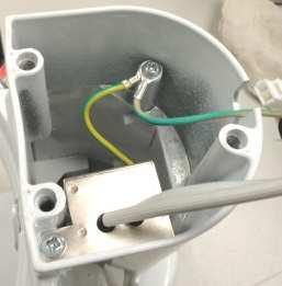
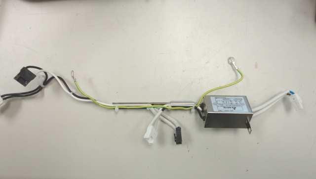
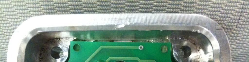
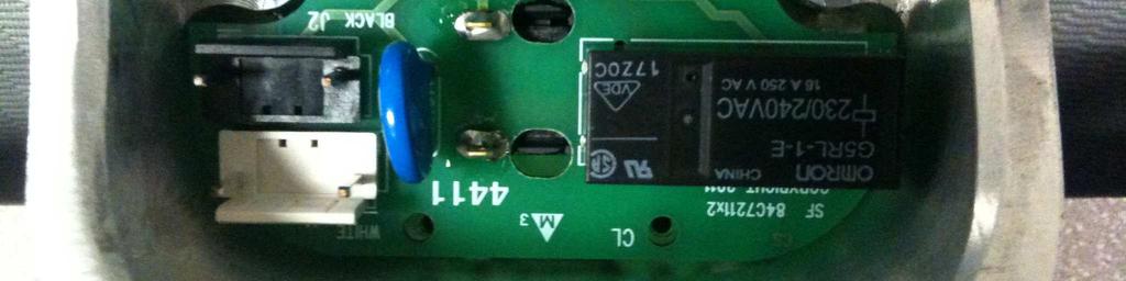
107 age 107 of 109 Report No hoto 5 hoto 6 hoto 7 hoto 8 hoto 9 hoto 10


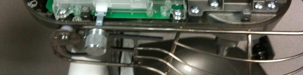
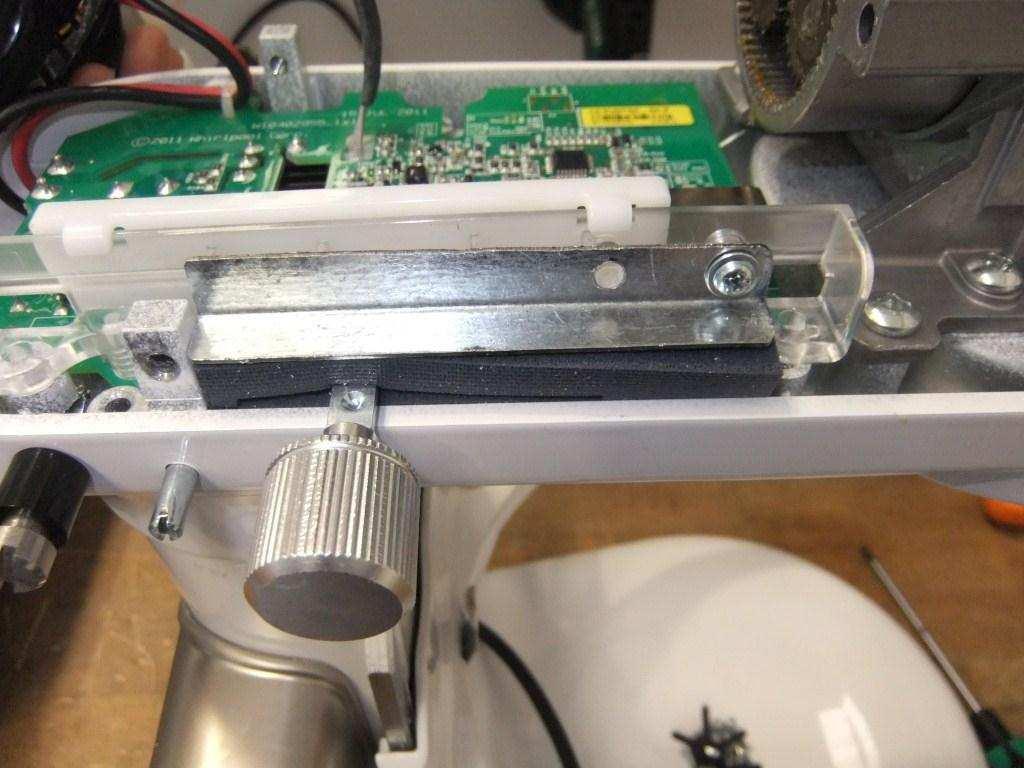
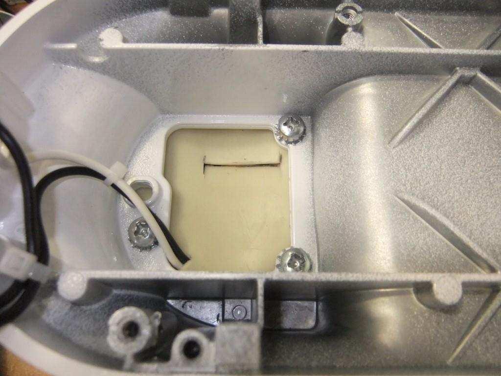
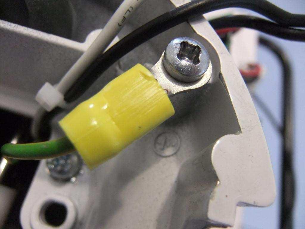
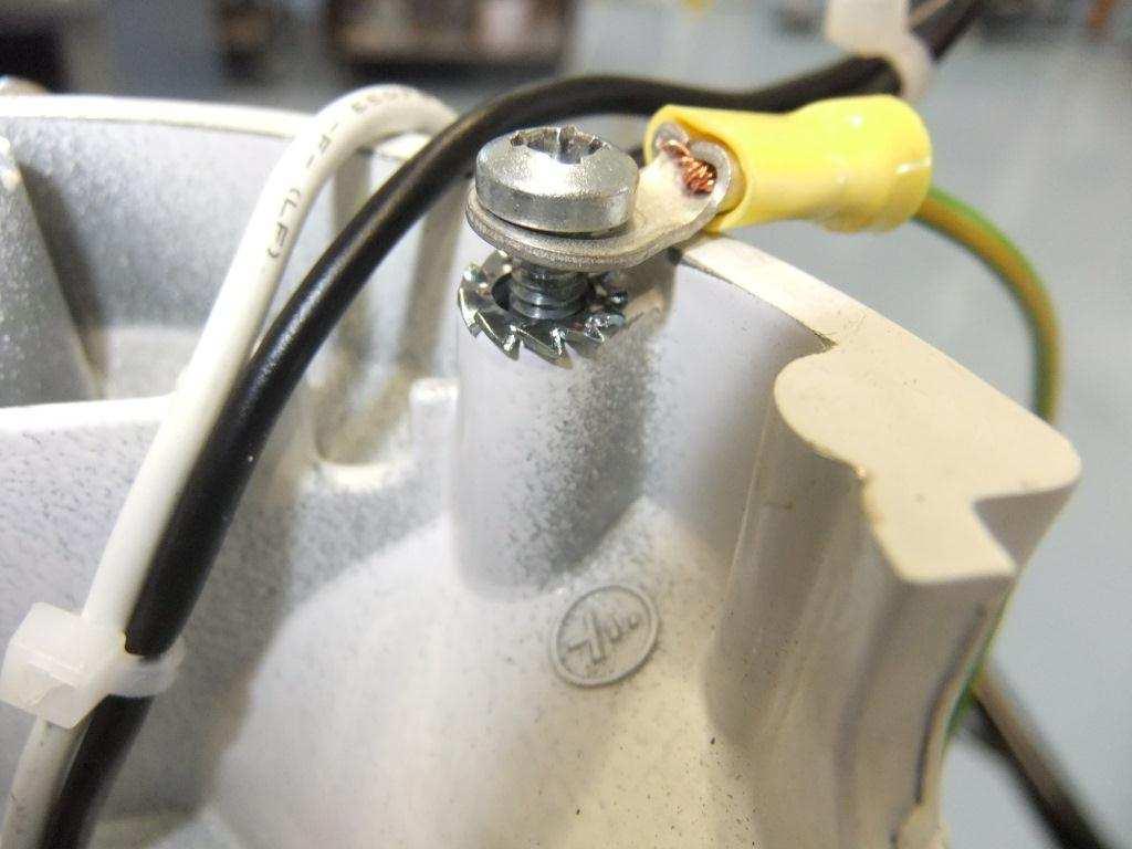
108 age 108 of 109 Report No hoto 11 hoto 12 hoto 13 hoto 14 hoto 15 hoto 16


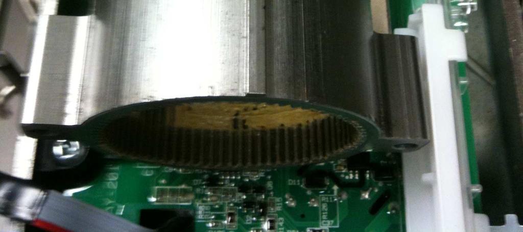

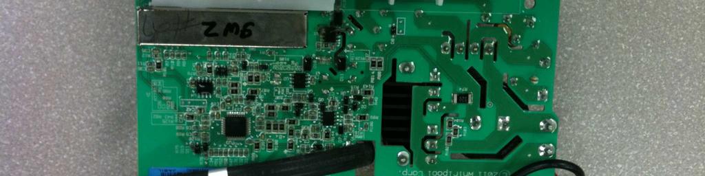
109 age 109 of 109 Report No hoto 17 hoto 18 hoto 19 hoto END OF TEST REORT ---
TEST REPORT IEC Safety of household and similar electrical appliances Part 2: Particular requirements for massage appliance
 Test Report issued under the responsibility of: SGS- CSTC TEST REORT Safety of household and similar electrical appliances art 2: articular requirements for massage appliance Report Reference No....: GZES100800181503
TEST REPORT IEC Safety of household and similar electrical appliances
 Test Report issued under the responsibility of: TEST REORT Safety of household and similar electrical appliances Report Number.... : 160100083SHA-001 Date of issue... : 2016-05-10 Total number of pages...
Tested by (name + signature)... : see on page 1. Approved by (name + signature)... : see on page 1. Tested by (name + signature)...
... : see on page 1. Approved by (name + signature)... : see on page 1. Tested by (name + signature)...") age 2 of 101 Report No. 28225175 001 Testing procedure and testing location: CB Testing Laboratory: Testing location/ address... : TÜV Rheinland InterCert Kft H-1132 Budapest, Váci út 48/A-B., Hungary
age 2 of 101 Report No. 28225175 001 Testing procedure and testing location: CB Testing Laboratory: Testing location/ address... : TÜV Rheinland InterCert Kft H-1132 Budapest, Váci út 48/A-B., Hungary
TEST REPORT IEC Safety of household and similar electrical appliances
 age 1 of 76 TEST REORT Safety of household and similar electrical appliances Report Number.... : 311280 Date of issue... : 11/11/2016 Total number of pages... : 76 Applicant s name... : Address... : Monotile
TEST REPORT IEC Safety of household and similar electrical appliances
 Test Report issued under the responsibility of: TEST REORT Safety of household and similar electrical appliances Report Number....: T211-0590/12 Date of issue...: 2012-11-22 Total number of pages... 93
See cover page See cover page
 Test Report issued under the responsibility of: TEST REORT Household and similar electrical appliances Safety art 2-60: articular requirements for whirlpool baths and whirlpool spas Report Number.... :
HISTORICAL OF SAMPLE RECEIVED
 TEST REORT N : LMO-14SE1873DTS HISTORICAL OF SAMLE RECEIVED LCIE CHI RECORDED N DETAIL OF THE SAMLE SECIAL REMARKS -- Original sample None COY OF RATING LATE: Other marking plates are same as above except
TEST REPORT IEC Safety of household and similar electrical appliances Part-2-41: Particular requirements for pumps
 Test Report issued under the responsibility of: TEST REORT Safety of household and similar electrical appliances art-2-41: articular requirements for pumps Report Number.... : ITD-14A0233HCS Date of issue...
TEST REPORT EN Household and similar electrical appliances. Safety. General requirements
 TEST REORT EN 60335-1 Household and similar electrical appliances. Safety. General requirements Report Reference No.... : 08.01.16.0258.01 Compiled by (+ signature)... : Approved by (+ signature)... :
NCB TÜV SÜD PSB Pte Ltd 1 Science Park Drive, Singapore Singapore
 age 1 of 100 Test Report issued under the responsibility of: NCB TÜV SÜD SB te Ltd 1 Science ark Drive, 118221 Singapore Singapore TEST REORT Safety of household and similar electrical appliances 删除的内容
TEST REPORT IEC Safety of household and similar electrical appliances Part 2 : Particular requirements for fans Report Reference No.
 Test Report issued under the responsibility of: TEST REORT Safety of household and similar electrical appliances art 2 : articular requirements for fans Report Reference No...: 28210014 001 Date of issue...:
Report No.: F690501/RF-SAF Testing location:
 age 2 of 81 Summary of testing: The tested samples comply with the requirement of the test specification Tests performed (name of test and test clause): All test Testing location: Copy of marking plate
TEST REPORT EN Household and similar electrical appliances - Safety Part 1: General requirements
 age 1 of 105 Test Report issued under the responsibility of: AN LAB CO d.o.o. Trgovacka 79 Belgrade 11030 Serbia TEST REORT EN 60335-1 Household and similar electrical appliances - Safety art 1: General
TEST REPORT ON THE SAFETY OF ELECTRICAL EQUIPMENT FOR PRODUCT INNOVATORS LTD ON A INFRARED TANKLESS HOT WATER SYSTEM
 TEST REPORT ON THE SAFETY OF ELECTRICAL EQUIPMENT FOR PRODUCT INNOVATORS LTD ON A INFRARED TANKLESS HOT WATER SYSTEM MODEL: IR 3000/4000/6000/8000 RH 3500/4500/6500/8500 REPORT NO. TRA-015720-34-00A Test
TEST REPORT IEC/EN Safety of household and similar electrical appliances
 age 1 of 69 TEST REORT Safety of household and similar electrical appliances Report Number.... : Complied by (+ signature)... : Gyewan, Kim Approved by (+ signature)... : Kangsun, Lee Date of issue...
TEST REPORT IEC Safety of household and similar electrical appliances
 Test Report issued under the responsibility of: TEST REORT Safety of household and similar electrical appliances Report Number.... : 27113131 001 Date of issue... : 22.10.2013 Total number of pages...
Test Report. Hotpoint Fridge Freezer Model FF175B
 Davy Avenue, Knowlhill Milton Keynes MK5 8NL, United Kingdom Telephone: +44 1908 85 7777 www.intertek.com age 1 of 95 Test Report Hotpoint Fridge Freezer Model FF175B Report No. 103250895MKS-001 Commercial-in-confidence
Safety of household and similar electrical appliances
 Test Report issued under the responsibility of: TEST REORT Safety of household and similar electrical appliances Report Number....: GZES171101935301 Date of issue...: 2018-03-16 Total number of pages...:
INSTITUTE OF TESTING AND CERTIFICATION (INDIA) PVT. LTD. COPY OF MARKING PLATE
 PVT. LTD. COPY OF MARKING PLATE") INSTITUTE OF TESTING AND CERTIFICATION (INDIA) VT. LTD. COY OF MARKING LATE Report No.-ITC/TEST/NN/1508/01 age 3 of 51 (INDIA) VT. LTD. 6 Classification Appliances shall be of one of the following 6.1
INSTITUTE OF TESTING AND CERTIFICATION (INDIA) VT. LTD. COY OF MARKING LATE Report No.-ITC/TEST/NN/1508/01 age 3 of 51 (INDIA) VT. LTD. 6 Classification Appliances shall be of one of the following 6.1
CERTIFICATE OF APPROVAL
 Certificate Number: TUV16069EA CERTIFICATE OF AROVAL.. TUVRheinland Authorised marking: TUV16069EA This is to certify that TOV Rhein/and Australia ty Ltd as accredited by JAS-ANZ in accordance with /SOI/EC
TEST REPORT IEC Safety of household and similar electrical appliances Part 2: Particular requirements for room heaters
 Test Report issued under the responsibility of: TEST REORT Safety of household and similar electrical appliances art 2: articular requirements for room heaters Report Number.... : 21140671 009 Date of
HW C.K. Park. H.S. Choi. KTC(Korea Testing Certification)
") Korea Testing Certification TEST REORT Household and similar electrical appliances - Safety art 2-17: articular requirements for blankets, pads and similar flexible heating appliances Report Reference
Korea Testing Certification TEST REORT Household and similar electrical appliances - Safety art 2-17: articular requirements for blankets, pads and similar flexible heating appliances Report Reference
TEST REPORT IEC Safety of household and similar electrical appliances Part 2 : Particular requirements for fans
 Test Report issued under the responsibility of: SGS Fimko Ltd. TEST REORT Safety of household and similar electrical appliances art 2 : articular requirements for fans Report Number.... : GZES151101346201
TEST REPORT EN Safety of household and similar electrical appliances
 age 1 of 54 TEST REORT EN 60335-1 Safety of household and similar electrical appliances Report Reference No.... : Complied by (+ signature)... : Approved by (+ signature)... : TK-CL110016 Byung il, Lee
re : CERTIFICATE OF APPROVAL TUV15998EA Certificate Number:
 Certificate Number: TUV15998EA CERTIFICATE OF AROVAL.. TUVRheinland Authorised marking: TUV15998EA This is to certify that TOV Rhein/and Australia ty Ltd as accredited by JAS-ANZ in accordance with /SOI/EC
ZH0505-GR-HT N/A IEC60335_2_9H LCIE
 Test Report issued under the responsibility of TEST REORT Safety of household and similar electrical appliances art 2: articular requirements for grills, toasters and similar cooking appliances Report
Test Report issued under the responsibility of: Report Number... : Date of issue... : Total number of pages...
 Test Report issued under the responsibility of: TEST REORT Household and similar electrical appliances - Safety art 2-17: articular requirements for blankets, pads and similar flexible heating appliances
TEST REPORT IEC/EN Safety of household and similar electrical appliances Part 2: Particular requirements for portable heating tools
 TEST REORT IEC/E 60335-2-45 Safety of household and similar electrical appliances art 2: articular requirements for portable heating tools Report umber....: DE113487 Date of issue...: 2015-06-09 Total
TEST REPORT IEC Safety of household and similar electrical appliances Part 2 : Particular requirements for fans
 age 1 of 114 Report o.: STUESO017022702211HS TEST REORT Safety of household and similar electrical appliances art 2 : articular requirements for fans Report umber.... : STUESO017022702211HS Date of issue...
TEST REPORT IEC Safety of household and similar electrical appliances Part 2: Particular requirements for room heaters
 SHEZHE LCS COMLIACE TESTIG LABORATORY LTD REORT O.: LCS170407067AS Report umber.... : TEST REORT IEC 60335-2-30 Safety of household and similar electrical appliances art 2: articular requirements for room
EC Declaration of Conformity According to Low Voltage Directive 2006/95/EC
 EC Declaration of Conformity According to Low Voltage Directive 2006/95/EC Manufacturer's Name: Dae Yeon Co., Ltd. Manufacturer's Address: San 31, Nokchon-ri, hwado-eup, Namyangju-si, Gyeonggi-do, Republic
BS EN : A2:2015 used in conjunction with BS EN : A11:2014 and BS EN 62233:2008
 Test Report Report No 8587907 Client Regal Care Shower Trays Ltd. Regal House, Smithy Lane, Scarisbrick, L40 8HN Authority & date SMO: 8587907, Date: August 9, 2016 Items tested ARESF Body Dryer with alternative
ZHEJIANG MAXGE ELECTRIC TECHNOLOGY CO., LTD. Address...:
 Test Report issued under the responsibility of: TEST REORT IEC 61008-1 Residual current operated circuit-breakers without integral overcurrent protection for household and similar uses (RCCBs) art 1: General
Oldal/ Page 2 / 2 Test report No.: Submersible Pump Test item description... :
 www.meei.hu Oldal/ age 2 / 2 Test report No.: 28205370 004 Test item description... : Trade Mark... : Submersible ump ELUMS Manufacturer... : ELUMS Kft. 4900 Fehérgyarmat, Vasvári ál u. 65. Model/Type
TEST REPORT EN :2012/AC:2014 Household and similar electrical appliances Safety Part 1:General requirements
 age 1 of 54 Ref. o: SCC(15)-40712A-3-10- LVD TEST REORT E 60335-1:2012/AC:2014 Household and similar electrical appliances Safety art 1:General requirements Report Reference o....: SCC(15)-40712A-3-10-
TEST REPORT IEC , 2 nd Edition Part 1: Equipment classification and requirements
 Test Report issued under the responsibility of: TEST REORT IEC 60825-1, 2 nd Edition art 1: Equipment classification and requirements Report Reference No....: EFSH15041135-IE-01-L01 Date of issue...: May
APPLICATION FOR LOW VOLTAGE DIRECTIVE On Behalf of BestSub Technologies Co Ltd 3D Vacuum Sublimation Machine Model: SZM3D
 ALICATIO FOR LOW VOLTAGE DIRECTIVE On Behalf of BestSub Technologies Co Ltd 3D Vacuum Sublimation Machine Model: SZM3D repared For : BestSub Technologies Co Ltd Rm810 Exchange Square, o.268, Dongfeng Zhong
ENEC NO2187. Nemko hereby grants the following manufacturer as licensee the right to affix this ENEC mark on the product(s) specified below.
 specified below.") ENEC NO2187 age 1/1 Order No. 135699 Licence for use of the here shown ENEC conformity mark : Based on: Agreement on the use of a commonly agreed Mark on Conformity for equipment complying with European
ENEC NO2187 age 1/1 Order No. 135699 Licence for use of the here shown ENEC conformity mark : Based on: Agreement on the use of a commonly agreed Mark on Conformity for equipment complying with European
APPLICATION FOR LOW VOLTAGE DIRECTIVE On Behalf of. Pest repeller Model: AN-A339
 age 1 of 71 Report o. 201404684S ALICATIO FOR LOW VOLTAGE DIRECTIVE On Behalf of Shenzhen Aosion hotoelectricity Co., Ltd. est repeller Model: A-A339 repared For : Shenzhen Aosion hotoelectricity Co.,
COSφ= V~ 50Hz IP20 Rev.A DehumiDification:1.0 l/h R22: Prated:45W PS: 4.4MPa Ps: 0.6MPa Temp.Class: T1 Weight:19kg
 12011245 001 age 2 of 60 Copy of the marking plate: Refrigerant: R22 ELECTRA MODEL: XD9 RODO.: Fuse: 10A(G) TYE: COSφ=0.95 220-230V~ 50Hz I20 Rev.A DehumiDification:1.0 l/h R22: rated:45w S: 4.4Ma s: 0.6Ma
Page 1 of 90 Report No. J0908CE
 age 1 of 90 Report o. J0908CE8888-0324 TEST REORT IEC/E 60 335-2-40 Household and similar electrical appliances Safety art 2-40: articular requirements for electrical heat pumps,air conditioners and dehumidifiers
IECEx TEST REPORT IEC Explosive atmospheres Part 0: Equipment General requirements
 ExTR Reference Number...: ExTR Free Reference Number...: 223531 Compiled by + signature (ExTL)...: Reviewed by + signature (ExTL)...: NO/NEM/ExTR12.0018/00 Stig André Norheim Arne Hortman Date of issue...:
Page 2 of 51. Copy of the marking plate: Refrigerant: R22
 12011921 001 age 2 of 51 Copy of the marking plate: Refrigerant: R22 ELECTRA MODEL:K-36SH ROD O.: Fuse: 25 A(G) TYE: COS =0.95 380-400V~ 50Hz I20 Rev.A Dehumidification: 4.0 l/h R22 rated: 3120 W S: 4.4Ma
TEST REPORT IEC Safety of laser products - Part 1: Equipment classification and requirements
 SHENZHEN LCS COMLIANCE TESTING LABORATORY LTD REORT NO.: LCS1611293204S TEST REORT Safety of laser products - art 1: Equipment classification and requirements Report Number.... : LCS1611293204S Date of
Modified Clauses of EN /A1:2004
 age 2 of 19 Report No.: 17003895 002 7. MARKING AND INSTRUCTIONS Modified Clauses of EN 60335-1/A1:2004 7.1 Symbol IEC 60417-5036, for the enclosure of electrically-operated water valves in external hosesets
K-SQ13, KA-SQ13, K-SQ14, KA-SQ14, KO-SQ13, KOA-SQ13, KO-SQ14, KOA-SQ14, K-SQ13C, KA-SQ13C, K-SQ14C, KA- SQ14C, KO-SQ13C, KOA-SQ13C, KO-SQ14C,
 age 2 of 14 Model/Type reference...: Ratings...: K-SQ13, KA-SQ13, K-SQ14, KA-SQ14, KO-SQ13, KOA-SQ13, KO-SQ14, KOA-SQ14, K-SQ13C, KA-SQ13C, K-SQ14C, KA- SQ14C, KO-SQ13C, KOA-SQ13C, KO-SQ14C, KOA-SQ14C,
TEST REPORT IEC Safety of laser products - Part 1: Equipment classification and requirements. TÜV Rheinland Shanghai Co., Ltd.
 Test Report issued under the responsibility of: TEST REORT IEC 60825-1 Safety of laser products - art 1: Equipment classification and requirements Report Number.... : 50089797 001 Date of issue... : 2017.07.25
TEST REPORT IEC Safety of laser products - Part 1: Equipment classification and requirements
 Test Report issued under the responsibility of: TEST REPORT IEC 60825-1 Safety of laser products - Part 1: Equipment classification and requirements Report Number.... : 102254161MPK-001L Date of issue...
Amendment to Test Report
 - Page 1 of 5 - Test Report issued under the responsibility of: Amendment to Test Report www.nemko.com This Amendment is valid only together with the main Test Report Report o....: 221968 Main Report o...:
IEC60601_1J. Medical electrical equipment Part 1: General requirements for basic safety and essential performance
 Page 1 of 157 Report No.: E309264-D1009-1-CB CB - IEC REPORT: Test Report issued under the responsibility of: IEC 60601-1 Medical electrical equipment Part 1: General requirements for basic safety and
KALDEWEI SKIN TOUCH WELLNESSPRODUKT
 KALDEWEI SKIN TOUCH WELLNESSRODUKT GS-Zertifikat für roduktsicherheit. SKIN TOUCH wurde durch den TÜV Rheinland untersucht. Die Untersuchung ergab, dass das SKIN TOUCH System für Badewannen den gestellten
IEC60601_1K. Medical electrical equipment Part 1: General requirements for basic safety and essential performance
 Page 1 of 165 Report No.: E309264-D1028-1/A0/C0-UL Test Report issued under the responsibility of: IEC 60601-1 Medical electrical equipment Part 1: General requirements for basic safety and essential performance
KINGDOM OF SAUDI ARABIA SASO/IEC /2012 SASO IEC
 SASO IEC 60335-2-6 HOUSEHOLD AND SIMILAR ELECTRICAL APPLIANCES- SAFETY PART 2-6: PARTICULAR REQUIREMENTS FOR STATIONARY COOKING RANGES, HOPS, OVENS AND SIMILAR APPLIANCES Date of SASO Board of Directors
AS/NZS :2003 Luminaires - Part 1: General requirements and tests
 Menu Home About this portal Latest updates Print Save Email Resource detail Citations AS/NZS 60598.1:2003 Luminaires - Part 1: General requirements and tests Table of Contents View on Information Provider
STANDARDS UPDATE NOTICE (SUN) ISSUED: August 23, 2017
 ISSUED: August 23, 2017") STANDARDS UPDATE NOTICE (SUN) ISSUED: August 23, 2017 STANDARD INFORMATION Standard Number: UL 412 Standard Name: Refrigeration Unit Coolers Standard Edition and Issue Date: 5 th Edition Dated August 22,
STANDARDS UPDATE NOTICE (SUN) ISSUED: August 23, 2017 STANDARD INFORMATION Standard Number: UL 412 Standard Name: Refrigeration Unit Coolers Standard Edition and Issue Date: 5 th Edition Dated August 22,
Attention. Please handle this product with care and inspect it regularly to ensure it is in good working order.
 Attention Please handle this product with care and inspect it regularly to ensure it is in good working order. If the product, power supply cord or plug shows any signs of damage: stop use, unplug and
TEST REPORT EN :2002+A1:2004+A11:2004+A2:2006+A12:2006 EN : 2003+A1:2008
 TEST REORT E 60335-1:2002+A1:2004+A11:2004+A2:2006+A12:2006 E 60335-2-23: 2003+A1:2008 Safety of household and similar electrical appliances art 2-23: articular requirements for appliances for skin or
EN50438 TEST REPORT SUMMARY. Requirements for the connection of micro-generators in parallel with public low-voltage distribution networks
 TEST REORT SUMMARY EN 50438 Requirements for the connection of micro-generators in parallel with public low-voltage distribution networks Report reference number... : 12TH0525-EN50438_SUM_0 Date of issue......:
INTERNATIONAL STANDARD
 INTERNATIONAL STANDARD IEC 62040-1-2 First edition 2002-08 Uninterruptible power systems (UPS) Part 1-2: General and safety requirements for UPS used in restricted access locations Alimentations sans interruption
AS/NZS IEC :2013
 AS/NZS IEC 61347.2.13:2013 (IEC 61347-2-13, Ed.1.0 2006, MOD) Australian/New Zealand Standard Lamp controlgear Part 2.13: Particular requirements for d.c. or a.c. supplied electronic controlgear for LED
Report reference No...: 10TH0052_AS4777_+_ISR_3 Tested by (printed name and signature)...: Urs Seifert. Approved by (printed name and signature)...
...: Urs Seifert. Approved by (printed name and signature)...") TEST REORT AS 4777.2:2005 and AS 4777.3:2005 with additional deviations for Israel Grid connection of energy systems via inverters Grid protection requirements Report reference No...: 10TH0052_AS4777_+_ISR_3
TEST REORT AS 4777.2:2005 and AS 4777.3:2005 with additional deviations for Israel Grid connection of energy systems via inverters Grid protection requirements Report reference No...: 10TH0052_AS4777_+_ISR_3
Rules for Classification and Construction Additional Rules and Guidelines
 VI Rules for Classification and Construction Additional Rules and Guidelines 7 Guidelines for the Performance of Type Approvals 7 Test Requirements for Statical Converters with Semi-Conductors Edition
INTERNATIONAL STANDARD
 INTERNATIONAL STANDARD IEC 60335-2-6 Fifth edition 2002-07 Household and similar electrical appliances Safety Part 2-6: Particular requirement for cooking ranges, hobs, ovens and similar appliances Appareils
IEC60601_1J. Medical electrical equipment Part 1: General requirements for basic safety and essential performance
 Page 1 of 170 Report No.: E309264-D1021-1/A1/C0-UL IEC REPORT: Test Report issued under the responsibility of: IEC 60601-1 Medical electrical equipment Part 1: General requirements for basic safety and
Test report. ifesesws^ Date: Number: T /17 Project file: C Pages: Product: Fixed general purpose LED luminaire
 Sl/Q ifesesws^ SLOVENSKA AKREDITACIJA SIST EN ISO/ 1EC 17025 L-009 Test report Number: roduct: roject file: Fixed general purpose LED luminaire Date: ages: C20170767 2017-04-26 12 Type reference: LA-FL/G-xxW-xxxxK-Rxxx/xxx-(D10kGy)
TC 61. Technical Committee 61 SAFETY OF HOUSEHOLD AND SIMILAR ELECTRICAL APPLIANCES
 Technical Committee 61 SAFETY OF HOUSEHOLD AND SIMILAR ELECTRICAL APPLIANCES Ensuring performance and safety of household electrical appliances in industrializing countries Seattle, Washington, USA: 2010-13-10
SPECIFICATION FOR GAPLESS METAL OXIDE DISTRIBUTION TYPE SURGE ARRESTERS WITH POLYMERIC HOUSING
 SPECIFICATION FOR GAPLESS METAL OXIDE DISTRIBUTION TYPE SURGE ARRESTERS WITH POLYMERIC HOUSING Page 1 of 10 CONTENTS 1 SCOPE 2 DEFINITIONS 2.1 SURGE ARRESTER 2.2 GAPLESS METAL-OXIDE SURGE ARRESTERS 2.3
TEST REPORT IEC MEDICAL ELECTRICAL EQUIPMENT
 Test Report issued under the responsibility of: TEST REORT MEDICAL ELECTRICAL EQUIMENT art 1-11: General requirements for basic safety and essential performance Collateral Standard: Requirements for medical
Test Report issued under the responsibility of:
 Test Report issued under the responsibility of: NCB TÜ V SÜ D PSB Pte Ltd 1 Science Park Drive, Singapore 118221 TEST REPORT IEC 61347-2-13 Part 2: Particular requirements: Section Thirteen d.c. or a.c.
HMN-D2 Insert Series
 HMN-D2 Insert Series Table of contents 1. SCOPE... 2 1.1. Content... 2 1.2. Qualification... 2 2. APPLICABLE DOCUMENTS... 2 2.1. TE Connectivity Documents... 2 2.2. Other Documents... 2 3. REQUIREMENTS...
FINAL ATEX REPORT ON EQUIPMENT FOR USE IN POTENTIALLY EXPLOSIVE ATMOSPHERES FOR GOLDEN PROMISE EQUIPMENT INC. FLOW MONITOR, GPE3000 SERIES,
 FINAL ATEX REPORT ON EQUIPMENT FOR USE IN POTENTIALLY EXPLOSIVE ATMOSPHERES FOR GOLDEN PROMISE EQUIPMENT INC. ON FLOW MONITOR, GPE3000 SERIES, REPORT NO. TRA-015825-33-00A ExTR Reference No. TRA-015825-33-00A
Laboratory Honeywell Technology Solutions, Bangalore-EMC Lab, 19/2, Devarabisanahalli Village, K.R. Puram, Varthur Hobli, Bangalore, Karnataka
 Last Amended on 07.10.2015 Page 1 of 18 I. EMC Test Facility 1. Electrical and Electronic Products, Process Control Devices, Lighting Control Products, Sensing and Control Devices, Electromechanical Products,
TABLE OF CONTENTS PART 4 - HAND TOOLS AND POWER DRIVEN PORTABLE TOOLS
 TABLE OF CONTENTS PART 4 - HAND TOOLS AND POWER DRIVEN PORTABLE TOOLS Page DEFINITIONS...4-1 GENERAL...4-1 CHAIN SAWS...4-3 BRUSH SAWS...4-4 POWDER ACTUATED TOOLS...4-5 PORTABLE CIRCULAR SAWS...4-5 PART
Consumer Products Services Germany GmbH Türkheim Germany
 TEST REORT SUMMARY EN 50438 Requirements for the connection of micro-generators in parallel with public low-voltage distribution networks Report reference number... : 11TH0290-EN50438_SUM_2 Date of issue......:
TEST REPORT IEC and/or EN Photobiological safety of lamps and lamp systems
 Test Report issued under the responsibility of: TEST REORT IEC 62471 and/or EN 62471 hotobiological safety of lamps and lamp systems Report Reference No.... : GZES130300236831 Tested by (name + signature)...
C Note! LGI16... Burner Controls. Building Technologies
 7 786 Burner Controls LGI16... Burner controls For use on industrial furnaces For burners in continuous operation Without fan control and air pressure supervision Flame supervision - with QR53... / QR55,
INTERNATIONAL STANDARD
 INTERNATIONAL STANDARD IEC 60335-2-6 Fifth edition 2002-07 Household and similar electrical appliances Safety Part 2-6: Particular requirements for stationary cooking ranges, hobs, ovens and similar appliances
RE-PR3-E-27 3-Phase Panel Mount 27kW
 Page 1 of 6 RE-PR3-E-27 3-Phase Panel Mount 27kW Features: Benefits: 0-10Vdc, 0-5Vdc, 4-20mA or manual via potentiometer control input Over temperature protection with auto reset Enclosed panel mounting
INTERNATIONAL STANDARD
 INTERNATIONAL STANDARD IEC 60601-2-2 Third edition 1998-09 Medical electrical equipment Part 2-2: Particular requirements for the safety of high frequency surgical equipment Appareils électromédicaux Partie
INTERNATIONAL STANDARD
 INTERNATIONAL STANDARD IEC 62052-11 First edition 2003-02 Electricity metering equipment (AC) General requirements, tests and test conditions Part 11: Metering equipment This English-language version is
ORDINANCE FOR TECHNICAL SPECIFICATIONS PERTAINING TO AEROSOL TYPE EXTINGUISHER APPLIANCES
 This translation is provisional translation for reference, formally refer to the original text. ORDINANCE FOR TECHNICAL SPECIFICATIONS PERTAINING TO AEROSOL TYPE EXTINGUISHER APPLIANCES (Ordinance of the
UV Flame Supervision System
 7 783 UV Flame Supervision System DETACTOGYR LFE50 Series 02 ISO 9001 The LFE50 is a self-checking UV flame supervision system designed for use with continuously operating burners or for burners running
Cat. N. Cat. N (s) 1. DESCRIPTION - USE 3. OVERALL DIMENSIONS. Technology : 4. PREPARATION - CONNECTION 2. PRODUCT RANGE
 1. DESCRIPTION - USE 3. OVERALL DIMENSIONS. Technology : 4. PREPARATION - CONNECTION 2. PRODUCT RANGE") Cat. N STOP & GO automatic resetting 87045 LIMOGES Cedex - FRANCE Telephone : + 33 5 55 06 87 87 Fax: + 33 5 55 06 88 88 Cat. N (s) : 4 062 88 / 4 062 89 CONTENTS PAGE 1. Description - Use... 1 2. Product
Cat. N STOP & GO automatic resetting 87045 LIMOGES Cedex - FRANCE Telephone : + 33 5 55 06 87 87 Fax: + 33 5 55 06 88 88 Cat. N (s) : 4 062 88 / 4 062 89 CONTENTS PAGE 1. Description - Use... 1 2. Product
LGA... Gas Burner Controls. Siemens Building Technologies Landis & Staefa Division
 7 418 ISO 9001 Gas Burner Controls LGA... The LGA... are used for the startup and supervision of atmospheric gas burners of low to medium capacity, without fan assistance, in intermittent operation. The
Cooker Hood LA-72-CAN.
 Cooker Hood LA-72-CAN EN www.luxairhoods.com WARNINGS Safety This equipment can be used by children aged 8 or more, people with physical, mental and sensory disabilities or inexperienced users it they
Test Report. Report No.: AGC SS01. Attestation of Global Compliance (Shenzhen) Co., Ltd.
 Co., Ltd.") age 1 of 14 Test Report Report o.: AGC10737170807SS01 RODUCT DESIGATIO : Laser pointer touch pen BRAD AME : /A MODEL AME : MO8097, MO8193 CLIET : Mid Ocean Brands B.V DATE OF ISSUE : Aug.18, 2017 STADARD(S)
age 1 of 14 Test Report Report o.: AGC10737170807SS01 RODUCT DESIGATIO : Laser pointer touch pen BRAD AME : /A MODEL AME : MO8097, MO8193 CLIET : Mid Ocean Brands B.V DATE OF ISSUE : Aug.18, 2017 STADARD(S)
TECHNICAL REPORT IEC TR General testing procedures for medical electrical equipment. Edition
 TECHNICAL REPORT IEC TR 62354 Edition 3.0 2014-09 General testing procedures for medical electrical equipment INTERNATIONAL ELECTROTECHNICAL COMMISSION PRICE CODE XH ICS 11.040 ISBN 978-2-8322-1856-3 Warning!
INTERNATIONAL STANDARD
 INTERNATIONAL STANDARD IEC 60335-2-17 Second edition 2002-10 Household and similar electrical appliances Safety Part 2-17: Particular requirements for blankets, pads and similar flexible heating appliances
INTERNATIONAL STANDARD
 INTERNATIONAL STANDARD IEC 60044-7 First edition 1999-12 Instrument transformers Part 7: Electronic voltage transformers This English-language version is derived from the original bilingual publication
IEC/TC IEC/TC44 IEC/TC44. Amd.1DC:201. Ed.3CD:2011. Ed.2.1:2008. Amd.1CDV ED.1: 一連番号 Ed.
 IEC/TC44 20-3-7 IEC/TC44 IEC/TC44 6 TC44 TC44 TC44 TC44 TC44 WD, CD, CDV TC44 一連番号 IEC 60027-:992 (Ed.) (995 corrected and reprinted) Letter symbols to be used in electrical technology Part : General 2
This is a preview - click here to buy the full publication ICS ISBN
 CONSOLIDATED VERSION IEC 60691 Edition 4.1 2019-01 colour inside Thermal-links Requirements and application guide INTERNATIONAL ELECTROTECHNICAL COMMISSION ICS 29.120.50 ISBN 978-2-8322-6430-0 Warning!
AUTOMATIC SLICING MACHINE
 AUTOMATIC SLICING MACHINE Instruction for use and maintenance Noaw s.r.l. Via Colombera, 27 21048 Solbiate Arno (VA) Tel. +39 0331 219 723 - fax. +39 0331 216 197 e-mail: noaw@noaw.it http://www.noaw.it
INTERNATIONAL STANDARD
 INTERNATIONAL STANDARD IEC 60335-2-30 Edition 5.0 2009-11 Household and similar electrical appliances Safety Part 2-30: Particular requirements for room heaters INTERNATIONAL ELECTROTECHNICAL COMMISSION
INTERNATIONAL STANDARD
 INTERNATIONAL STANDARD IEC 60335-1 Edition 4.1 2004-07 Edition 4:2001 consolidated with amendment 1:2004 Household and similar electrical appliances Safety Part 1: General requirements This English-language
LFE50. UV Flame Safeguard. Siemens Building Technologies HVAC Products DETACTOGYR. Series 02
 7 783 ISO 9001 DETACTOGYR Flame Safeguard Series 02 The... together with the QRA50M / QRA51M form a self-checking flame supervision system (DETACTOGYR ) designed for use with continuously operating oil
EUROBOX SERIES TYPES CM...N SM...N MM...N
 EUROBOX SERIES TYPES CM...N SM...N MM...N AUTOMATIC CONTROL SYSTEMS FOR GAS BURNERS AND GAS BURNING APPLIANCES WITH OR WITHOUT FAN (MANUAL RESET) DESCRIPTION This series of electronic systems is suitable
INTERNATIONAL STANDARD NORME INTERNATIONALE
 IEC 62031 INTERNATIONAL STANDARD NORME INTERNATIONALE Edition 1.0 2008-01 2 62031 IEC:2008 CONTENTS FOREWORD...3 INTRODUCTION...5 1 Scope...6 2 Normative references...6 3 Terms and definitions...7 4 General
INTERNATIONAL STANDARD
 INTERNATIONAL STANDARD IEC 60939-2 Second edition 2005-02 Passive filter units for electromagnetic interference suppression Part 2: Sectional specification Passive filter units for which safety tests are
Contact Details. Please note that some of the contact details on this PDF document may not be current.
 Contact Details Please note that some of the contact details on this PDF document may not be current. Please use the following details if you need to contact us: Telephone: 0844 879 3588 Email: customer.services@gdcgroup.co.uk
SECTION AUTOMATIC TRANSFER SWITCHES
 SECTION 26 36 23 AUTOMATIC TRANSFER SWITCHES PART 1 - GENERAL 1.1 RELATED DOCUMENTS A. General provisions of the Contract, including General and Supplementary Conditions and Division 01 Specification Sections,