COLD BOX INSTALLATION, OPERATION, AND MAINTENANCE
|
|
|
- Shannon Greer
- 6 years ago
- Views:
Transcription

1 COLD BOX INSTALLATION, OPERATION, AND MAINTENANCE
2 Basic Cold Box Components Chart Energy & Chemicals (E&C) designs and manufactures process equipment utilized primarily for cryogenic applications such as industrial gas, hydrocarbon, LNG, petrochemical (ethylene) and other refinery applications. Chart E&C's engineering staff is capable of assisting customers with integrating our equipment into the plant/process design. Copyright 2009 by Chart Energy & Chemicals, Inc.
3 COLD BOX INSTALLATION, OPERATION, & MAINTENANCE Table of Contents 1 Introduction Cold Box Basic Components Frame Tubing Internal Support Members Side Panels Roof & Floor Panel Flexible Insulated Closeouts Lifting Lugs Base Plates Emergency Vent / Upper Manway Breather Valve Lower Manway Perlite Fill Connections Perlite Drain Connections Stream Identification Tags Stainless Steel Duplicate Nameplates Optional Equipment Codes and Materials of Construction Nitrogen Purge System Principles of Operation Dehumidification Purge Continuous Purge Transition Joints Allowable Pipe Loads Handrails, Ladders, and Platforms Standard Factory Testing Cold Box Piping Test Standard Cold Box Casing Testing Painting Loose Parts Valves and Instrumentation Control Valves Temperature Elements Junction Box Pressure Tubing Flow Meters Arrival Inspection and Storage First Arrival Storage Lifting and Handling Installation Base Plate Installation General Setting Recommendations Temporary Bracing Perlite Insulation Nitrogen Purge System Flanged Connections Pressure Testing with Shipping Blinds Gaskets and Bolting Bolt Torques Tightening Pattern Installation Checklist Testing and Operation Heat Exchangers Strainers Testing of Piping System Maintenance General Repairs and Service Forward Chart Energy & Chemicals, hereafter referred to as Chart, brings together the quality products and individual best working practices of the former Altec, Marston, and Process Systems International organizations. The following instructions are Chart Energy & Chemicals recommendations regarding installation, operation, and maintenance of cold boxes. Refer to Chart Energy & Chemicals BAHX IOM Manual for specific information regarding the installation, operation, and maintenance of brazed aluminum plate-fin heat exchangers. The contractor or owner installing Chart equipment should pay careful attention to these recommended procedures along with any lifting and handling instructions provided with individual units. When these recommendations are followed, extended and reliable service of the equipment can be expected. Recommended procedures do not, however, cover all possible variations in equipment design or provide answers to all specific installation and operating questions which may occur. If for any reason these recommendations cannot be followed or any questions arise, do not hesitate to contact Chart for further information. Caution Throughout this manual, safety items are labeled with the caution mark shown here. These items should be read with care and thoroughly understood prior to any installation, operation, or maintenance of Chart equipment. Failure to properly follow instructions so designated could result in ruptures or other dangerous situations which could cause serious personal injury or death. Do not make modifications to the equipment or deviate from the procedures recommended in this manual. 3


![1.2 Internal Support Members Main support members for vessels operating below -20 F [-28.9 C] are fabricated from stainless steel or low temperature carbon steel. A minimum of 0.50 in [12.](/docs-images/74/70083807/images/4-3.jpg "7 mm] of phenolic canvas base material, Micarta, is placed between the support angles of internal equipment and their support beams. The phenolic canvas serves two purposes.")
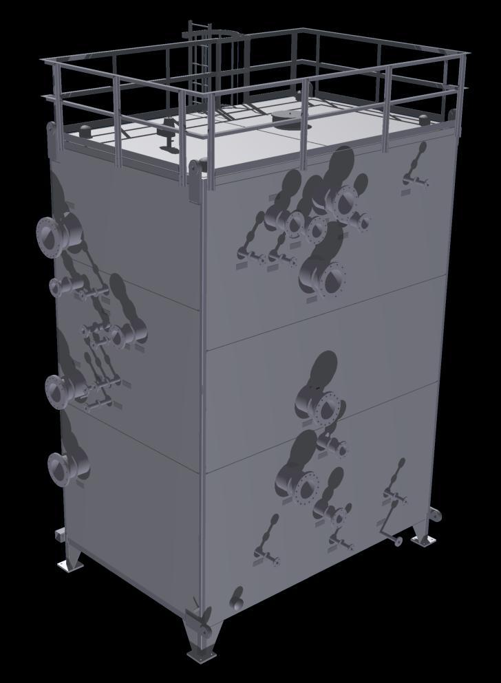
4 CHART ENERGY & CHEMICALS 1 Introduction 1.1 Cold Box Basic Components A cold box consists of a carbon steel casing, usually rectangular in shape that supports and houses heat exchangers, piping, other related cryogenic equipment, and insulation material in an inert atmosphere Frame Tubing The main exterior framing typically consists of vertical carbon steel columns connected by horizontal members at various elevations as necessary for support of internal equipment Internal Support Members Main support members for vessels operating below -20 F [-28.9 C] are fabricated from stainless steel or low temperature carbon steel. A minimum of 0.50 in [12.7 mm] of phenolic canvas base material, Micarta, is placed between the support angles of internal equipment and their support beams. The phenolic canvas serves two purposes. First, it provides a smooth surface upon which the supports can slide due to thermal contraction of the equipment. Second, it impedes heat transfer into the support members to avoid frost spots on the exterior of the cold box Side Panels The cold box is enclosed with in [4.8 mm] carbon steel side panels to create an air tight enclosure Roof & Floor Panel Floor and roof panels are 0.25 in [6.4 mm] carbon steel plate. For safety purposes, all roof panels are made of raised pattern plate Flexible Insulated Closeouts The process connections penetrate through the cold box panels via flexible closeouts. The closeouts create an air tight seal while accommodating the natural piping movement that occurs when the equipment is operated. See Figure Lifting Lugs The cold box includes adequate lifting lugs for horizontal lifting during transportation to site and vertical lifting during the erection sequence at site Base Plates The base plates are fabricated by Chart and shipped loose. See section 4.1 for further details Emergency Vent / Upper Manway The top of the cold box is fitted with an emergency relief hatch to prevent over-pressurization of the cold box structure in case of an internal equipment leak. The vent is set to open at 4 in H 2 O [10 mbarg]. The relief hatch serves a dual purpose as a Figure 1.1. Standard Nameplates Figure 1.2. Flexible Closeout Boot 4
![COLD BOX INSTALLATION, OPERATION, & MAINTENANCE 20 in [508 mm] manway on the top of the cold box. It can also be used as a perlite fill. See Figure 1.](/docs-images/74/70083807/images/5-1.jpg "5 1.1.9 Breather Valve The top of the cold box is fitted with a breather valve with a 3 in H 2 O [7.5 mbarg] pressure setting and a 2.2 in H 2 O [5.4 mbarg] vacuum setting. See Figure 1.5. To prevent damage during shipping, the breather valve ships loose and is to be installed at site.")
![1.1.10 Lower Manway A 25 in [635 mm] manway is typically installed on the cold box near the floor. See Figure 1.3. 1.1.15 Optional Equipment Upon request, Chart can provide other optional equipment to the cold box including, but not limited to the following: 1.](/docs-images/74/70083807/images/5-2.jpg "Perlite drain valves. 2. Handrails 3. Clips for customer designed and installed ladders and platforms. 4. External ladders and platforms. 1.")
![1.11 Perlite Fill Connections The cold box is typically fitted with 6 NPS [DN 150] perlite fill connections on the roof. Fill connections are threaded and furnished with caps. 1.1.12 Perlite Drain Connections The cold box is typically fitted with 6 NPS [DN 150] perlite drains on the side of the cold box flush with the floor.](/docs-images/74/70083807/images/5-3.jpg "Drain connections are threaded and fitted with caps. 1.")
5 COLD BOX INSTALLATION, OPERATION, & MAINTENANCE 20 in [508 mm] manway on the top of the cold box. It can also be used as a perlite fill. See Figure Breather Valve The top of the cold box is fitted with a breather valve with a 3 in H 2 O [7.5 mbarg] pressure setting and a 2.2 in H 2 O [5.4 mbarg] vacuum setting. See Figure 1.5. To prevent damage during shipping, the breather valve ships loose and is to be installed at site Lower Manway A 25 in [635 mm] manway is typically installed on the cold box near the floor. See Figure Optional Equipment Upon request, Chart can provide other optional equipment to the cold box including, but not limited to the following: 1. Perlite drain valves. 2. Handrails 3. Clips for customer designed and installed ladders and platforms. 4. External ladders and platforms Perlite Fill Connections The cold box is typically fitted with 6 NPS [DN 150] perlite fill connections on the roof. Fill connections are threaded and furnished with caps Perlite Drain Connections The cold box is typically fitted with 6 NPS [DN 150] perlite drains on the side of the cold box flush with the floor. Drain connections are threaded and fitted with caps Stream Identification Tags Each process connection is clearly labeled with a stainless steel stream identification tag. See Figure Stainless Steel Duplicate Nameplates For each code vessel inside the cold box, a duplicate stainless steel nameplate is attached to the outside of the cold box. See Figure 1.1. Figure 1.4. Stainless Identification Tags Figure 1.3. Cold Box Manway Figure 1.5. Breather Valve and Emergency Vent Hatch 5
6 CHART ENERGY & CHEMICALS 1.2 Codes and Materials of Construction The following codes and standards are routinely used by Chart. ASTM - American Society for Testing and Materials AISC - American Institute of Steel Construction AWS - American Welding Society ASME - American Society of Mechanical Engineers ANSI - American National Standards Institute ASCE - American Society of Civil Engineers UBC - Uniform Building Code SSPC - Steel Structures Painting Council PIP - Process Industry Practices All material is new and certified. Cold box structure and panels are certified to the following ASTM specifications. Item Structural steel shapes Carbon steel structural tubing Stainless steel structural tubing Raised pattern safety plate (roof) Floor plate ASTM Specification A36 A500 Gr. B A554 Gr. MT304 A786 A36 Stainless steel plate A Low temperature carbon steel plate A516 Gr. 70 Stainless steel bolts (structural) Side panels A320 Grade B8 A Principles of Operation The pressure regulator is used to maintain a constant pressure of 5 psig [0.34 barg] upstream of the needle valve. The needle valve is then used to maintain a constant flow rate as read on the flow meter. Changes in box pressure due to leaks will have a negligible effect on the flow rate. The nitrogen normally flows through the entire box before leaving via the breather valve on the roof which is set to maintain a positive pressure on the box of 3 in H 2 O [7.5 mbarg]. If leaks develop in the cold box casing, the box pressure may drop, but should remain positive. Since the flow rate is much higher than the designed casing leak rate, nitrogen should continue to flow to the top of the box. If internal equipment develops a leak, the breather valve will continue to vent, but the box pressure will rise. If it reaches 4 in H 2 O [10 mbarg], the emergency vent will open to prevent structural damage to the casing. Unless the process piping leak is massive, the pressure will drop after the emergency vent has opened. The emergency vent cover should not be replaced until the cause of the leak has been corrected. In addition to its venting function, the breather valve also acts as a vacuum breaker set at 2.2 in H 2 O [5.4 mbarg]. This minimizes the influx of moisture and prevents collapse of the casing Dehumidification Purge Prior to start-up, the cold box shall be purged of moisture that may have entered. After installation of the breather valve, emergency vent, and perlite, set the nitrogen flow rate to provide approximately two volume changes of the casing every 24 hours. Maintain this purge at least two days. 1.3 Nitrogen Purge System A pipe is laid on the inside perimeter of the box floor to act as a nitrogen purge header. The pipe has holes in it to distribute nitrogen throughout the box, and is connected to a flange outside of the cold box. A continuous nitrogen supply shall be run through the box during operation. See Figure 1.6. Figure 1.6. Typical Nitrogen Purge System 6

7 COLD BOX INSTALLATION, OPERATION, & MAINTENANCE Continuous Purge Normal atmospheric pressure and temperature changes can cause the casing to breathe. Hence, a continuous purge set at a rate to provide approximately one volume change of the casing every 24 hours should be performed. It should also be performed during shutdowns to prevent ingress of moisture into the perlite. If a continuous purge is not conducted during a shutdown, even though the casing is not opened, a check should be made for contaminants upon start-up to see if a dehumidification purge should be performed. 1.4 Transition Joints If there is a change from aluminum piping to steel piping inside the cold box, an aluminum to stainless steel transition joint is used. Transition joints are bonded materials made through a variety of methods, all of which have no parts that require maintenance. 1.5 Allowable Pipe Loads A table indicating maximum allowable pipe loads on brazed aluminum heat exchangers is provided with the design package. This table indicates the maximum allowable bending moment and axial load which may be applied at each nozzle to header joint on the exchanger. These maximum loads are not to be applied simultaneously. Instructions for summing applied moments and forces are supplied with the table. Pipe loads on vessels should be analyzed using standard industry practices, such as WRC-107. It is the customer s responsibility to provide sufficient piping flexibility or piping supports in the customer piping to ensure that the combined loads on each nozzle on the internal equipment are within the allowable limits specified. When a unit is supplied with transition joints, the applied loads on the transition joints must be checked against the allowable loads recommended by the joint manufacturer. Warning Failure to provide sufficient pipe flexibility or piping supports could result in combined pressure and external pipe loads being applied which exceed the allowable loads and cause failure of the unit or transition joint. 1.6 Handrails, Ladders, Platforms Handrails, ladders, or platforms are not provided by Chart unless specified in the purchase order. When provided by Chart, these items are generally trial fit at Chart s fabrication facility and then shipped loose. See Figure 1.7. Figure 1.7. Installed Ladder, Handrails, and Platform 7
8 CHART ENERGY & CHEMICALS 1.7 Standard Factory Testing Cold Box Piping Test After completion of welding of all pipe spools to equipment within the cold box, the piping is pneumatic tested at Chart s fabrication facility. This test is performed at 1.1 times the design pressure of each stream per ASME B31.3. The pressure is then dropped to the design pressure and a soap film leak test is performed on all piping welds Standard Cold Box Casing Testing To assure a sturdy leak tight construction, the cold box is proof tested with air at 4 in H 2 O [10 mbarg] at the Chart fabrication facility. No obvious leakage is allowed. The box is then leak tested with air at 3 in H 2 O [7.5 mbarg], using a standard soap test procedure and pressure decay test. 1.8 Painting Chart has extensive experience coating the external carbon steel surfaces of cold boxes using a variety of paint systems. The purchaser has the option to specify the paint system to be used on a particular project. The inside of the cold box is a dry, air tight environment under nitrogen purge, therefore painting on the inside is not required but can be accommodated upon request. Refer to the Chart generated project paint specification for detailed information on the applied coating system. 1.9 Loose Parts In order to prevent damage during shipping, several parts will ship loose with the cold box. These items include the breather valve, emergency vent hatch, any ladders or handrails, control valve actuators, and base plates. These parts must be assembled on site Valves and Instrumentation Control Valves Chart may provide control valves as part of a cold box assembly. Typically, extended bonnet control valves are used, which protrude through the cold box wall as depicted in Figure 1.8. This arrangement has no bolted connection inside the cold box. The actuator and positioner are attached to the end of the extension outside of the cold box. This allows all wiring and pneumatic lines to be connected and all valve maintenance to be performed outside of the cold box. The customer is typically responsible for bringing wires and pneumatic lines up to the control valve positioner. Because the purpose of a control valve is to drop the pressure in a line, the valves are typically not the same size as the main pipeline. The valves will have reducers on their inlets and outlets, and the inlet pipeline size may be different than the outlet pipeline size. The valve bonnet penetrates through the cold box wall and is closed out using a flexible boot as depicted in Figure Temperature Elements (RTD s and Thermocouples) Chart may provide integral temperature elements installed into the equipment inside a cold box. Depending on the customer s needs, the temperature elements will terminate outside of the box either with loose leads or inside a junction box. Inside the cold box, temperature elements are contained within air tight shielding. The preferred type is flexible shielding per Figure The wire is routed through unistrut, as shown in Figure 1.12, to protect it and guide it down to the wire penetration locations. There are different ways to mount temperature elements to the equipment. A thermowell installed directly into a pipe is shown on the left side of Figure A thermowell installed directly into a brazed aluminum heat exchanger layer is shown on the right side of Figure Figure 1.8. Control Valve Setup Figure 1.9. Control Valve Close-out 8
9 COLD BOX INSTALLATION, OPERATION, & MAINTENANCE Junction Box Chart generally provides a junction box on the outside of the cold box in which all temperature element lines terminate. This simplifies the process of wiring plant instrumentation and control systems related to the cold box since the wiring can conveniently be connected to the terminals in the junction box. When supplied, Chart typically uses a NEMA 4X rated junction box Pressure Tubing Tubing for pressure measurement is normally in [9.5 mm] diameter and routed directly from the process line to a pressure gauge or transmitter on the outside of the box. It is desirable to vaporize any fluid before it reaches the measuring device. To achieve this, the tubing is routed with a gentle rise from the process line to the box wall and then routed near the box wall until it reaches the measuring device. See Figure Figure Temperature Element Shielding Flow Meters When flow meters are required, Chart uses a venturi or orifice type flow meter for measuring process flow inside the cold box. These devices measure flow without any moving parts inside the cold box, eliminating maintenance. Where it is desired to measure the flow into the N 2 purge system, a simple ball bearing type flow meter is recommended. Figure Unistrut for Wiring Figure In-pipe and In-layer Thermowells Figure Pressure Tubing 9

10 CHART ENERGY & CHEMICALS 2. Arrival Inspection and Storage 2.1 First Arrival Upon arrival the cold box should be inspected for shipping damage and contamination. Closely examine the cold box for external damage. Warning The cold box is a confined space. Proper safety procedures and precautions for confined space entry must be practiced. Failure to follow confined space entry precautions could result in serious personal injury or death. For units shipped pressurized with dry air or nitrogen, each stream is provided with a valve and coupling to which a pressure gauge can be mounted. See Figure 2.1. A positive pressure should be indicated on the gauge when the valves are opened. If a gauge does not indicate a positive pressure and the valve and coupling connections have been checked for leakage, the stream should be repressurized with dry air or nitrogen to the lesser of 15 psig or one-third the stream s design pressure. If a leak in the unit, shipping damage, or internal shipping contamination is confirmed, consult Chart for further direction. 3. Lifting and Handling Lifting and handling instructions are provided with all units. All handling must be in accordance with the supplied instructions. Contact Chart prior to moving the unit if the handling instructions are missing or additional information is required. Warning Failure to handle the cold box properly during movement and erection could result in the cold box being dropped or other accidents, which could cause serious personal injury or death as well as irreparable damage to the unit. Confirm the weight, dimensions, and lift connection locations of the unit. Select the appropriate hoisting machines, spreader bars, slings, shackles, and other material handling tools in consideration of the height, weight, and the angle and direction of the hoisting. Carefully inspect slings, cabling, and shackles for wear. Care should be taken to avoid impacts to the unit. Rough or improper handling can cause damage to the internal construction of the cold box. 2.2 Storage When storing a cold box the following points should be considered: Prior to storage, all connections shall be inspected. The closeout boots should be inspected to ensure that they are not damaged and are sealed tight. The shipping valves, as depicted in Figure 2.1, should be opened briefly to verify the shipping pressure is intact. The valve should be shut after checking shipping pressure to prevent loss of shipping pressure in case the pressure gauge gets damaged. Cold boxes should be stored in the as shipped position with the weight concentrated at the structural frame members in accordance with the construction drawing. Figure 2.1. Shipping Valve 10

11 COLD BOX INSTALLATION, OPERATION, & MAINTENANCE Figure 3.1 Typical Lifting Drawing Figure 3.2 Cold Box Lift onto Shipping Barge 11

12 CHART ENERGY & CHEMICALS 4. Installation 4.1 Base Plate Installation The cold box will generally be mounted to the foundation by square base plates at the end of each column. Chart s standard practice is to supply base plates as shipped loose items with the cold box. The recommended work flow is as follows. 1. Set base plates on anchor bolts. 2. Shim under base plates to assure levelness. 3. Secure base plate to anchor bolts. 4. Lift and set cold box on plates. 5. Loosen nuts on base plates. 6. Weld base plates to corner posts and intermediate columns. 7. Resecure base plate to anchor bolts. 8. Fill in and seal gaps underneath base plates with grout. This method ensures that any unfavorable tolerances will not cause difficulty fitting the cold box onto the anchor bolts. 4.2 General Setting Recommendations Chart provides detailed lifting drawings for use when transporting, moving, and erecting the cold box. Spreader beam requirements are shown on the lifting drawings and shall be used to prevent over stressing the lifting components. The scope of supply for the lifting equipment is identified on the lifting drawings as well. 4.4 Perlite Insulation Perlite is typically used to insulate the open space inside the cold box. Perlite is a naturally occurring siliceous volcanic rock that expands 4 to 20 times its original volume when heated. Perlite can either be expanded on site or purchased in bulk already expanded. It is critical to keep the perlite dry during installation. Therefore, it is recommended that the top of the box be covered with plastic sheeting over scaffolding to prevent precipitation from accidentally entering the cold box during installation. Because perlite is extremely light, this also helps prevent wind from interfering with the installation process. The perlite will tend to settle over time. It is recommended to top off the perlite about 1 month after the initial filling. 4.5 Nitrogen Purge System Upon installation of the cold box, the nitrogen purge system must be fitted with the necessary components for operation. Typically a regulator is used to drop the pressure of the nitrogen purge supply to a low value, normally 5 psig [0.34 barg]. Then a needle valve and flow meter are used to finely control the flow rate. The breather valve and emergency relief hatch must also be installed to ensure proper function of the system. The fiberglass wrapping, depicted in Figure 4.1, should not be removed. The wrapping is used to prevent perlite insulation from entering into the N 2 distribution holes in the bottom of the pipe. 4.3 Temporary Bracing Before shipping, any piping potentially susceptible to excessive deflection or shipping vibration is fitted with temporary bracing. These shipping supports are painted yellow and must be removed after the cold box is up righted and connected to field piping, but before it is filled with insulation. A drawing marked with the locations of all temporary bracing is provided with shipment. Exercise extreme care to keep all steel working torches and flame cutting tools at a proper distance from internal equipment in order to prevent damage to brazed joints and to the internal construction. Figure 4.1 N 2 Purge 12
13 COLD BOX INSTALLATION, OPERATION, & MAINTENANCE 4.6 Flanged Connections Pressure Testing with Shipping Blinds Chart s standard practice is to ship flanged connections with blind flanges and bolting that are capable of handling the full rated pressure of the flange. However, in cases of tight shipping constraints, the flanged connections may be shipped with thinner blind flanges (covers), which are designed for the shipping pressure of the unit. Warning If a field pressure test is to be conducted with the shipping blinds at a pressure above the shipping pressure, contact Chart to confirm the maximum working pressure rating of the blinds. Pressurization of a cold box assembly with blind flanges not designed for pressure test purposes could result in a rupture of the flanged ends and cause serious injury or death Gaskets and Bolting Exercise care to protect the machined face of the flange against scratches, dents, or other damage that would reduce the effectiveness of the gasket in making a proper seal. The two mating surfaces of the flanges shall be parallel with each other prior to connecting. Flange faces shall be aligned to the design plane to within 0.06 in/ft [5 mm/m] maximum, measured across the diameter of the flange mating surface, and flange bolt holes should be aligned to within 0.12 in [3 mm] maximum offset. Chart recommends Flexitallic Flexpro gaskets or equivalent (m = 2.0, y = 2500 psi [17.2 MPa]). If stainless steel spiral wound gaskets are used Chart recommends they be the low seating stress type such as Flexitallic LS, (m = 3.0, y = 5000 psi [34.5 MPa]). Warning Installed bolts and gaskets shipped with the blind flange must not be used for making final connections as they are not designed for cryogenic service. Failure to replace the shipping bolting with bolting adequate for the intended service can result in rupture of the flange joint and could cause serious personal injury or death. Appropriate grade stainless steel bolts and nuts shall be used for the final field connection for cryogenic service. Stainless steel washers shall be used under the bolt heads or nuts on the aluminum flange, and threads should be lubricated for proper torque wrench applications Bolt Torques All bolting shall be given a final tightening by torque wrench. Bolts are to be sequentially torqued to the full value shown in the following table and then re-torqued after 15 minutes. Torque values are based on a resultant bolt stress of 25,000 psi [172 MPa] assuming well lubricated studs, nuts and washers Tightening Pattern All bolting shall be gradually pulled up by a crossover sequence. A minimum of two threads shall extend beyond the top of each nut. Bolt Size in Threads per in Torque ft lb [N m] Torque Increments [34] Snug, [68] then full torque [125] [193] Snug, [294] 1/2 torque, then full [424] torque [594] [808] [1045] Snug, [1356] 1/3 torque, 2/3 torque, [1695] then full [2104] torque [2553] Snug, [3684] 1/4 torque, 1/2 torque, [5084] 3/4 torque, [6808] then full torque [8898] 13
14 CHART ENERGY & CHEMICALS 4.7 Installation Checklist For reference, the following is a recommended check list to be completed before placing the cold box into operation. This list is not intended to be comprehensive for all situations, but it provides a basis. 1. Install base plates and set cold box. 2. Install nitrogen purge components. 3. Attach connecting piping. 4. Remove temporary bracing. 5. Install ladders, handrails, and platforms, where applicable. 6. Connect instrumentation, where applicable. 7. Install perlite. 8. Perform dehumidification purge with nitrogen. 9. Commence continuous nitrogen purge. 5. Testing and Operation 5.1 Heat Exchangers Refer to Chart Energy & Chemicals BAHX IOM Manual for specific testing instructions for brazed aluminum heat exchangers. 5.2 Strainers Process fluids having the potential of containing particulates should be filtered with a 177 micron (80 Mesh Tyler Standard) screen, or finer, just before entering the cold box. The user should consider a dual filter system with suitable valving to allow filters to be changed without shut down. 5.3 Testing of Piping System Warning Do not exceed the test pressure value stated on the cold box nameplate or construction drawing. Overpressurization of the cold box could result in a rupture and cause serious personal injury or death. Most codes require a pressure test of the piping system after the unit is installed. Residual test liquid which may become trapped within the unit cannot be tolerated, since during operation the liquid may freeze and cause serious damage and possible failure of the equipment. Therefore a pneumatic test is most often performed. The pneumatic proof test pressure shall comply with the requirements of the applicable code, but shall not exceed the test pressure shown on the drawing. Each stream is to be isolated using blind flanges of the appropriate pressure rating. When isolation of the stream can only be achieved by closing line valves, extreme care shall be taken to assure that leakage across the valve does not over pressurize the adjacent stream. Each stream shall be fitted with at least two pressure gauges, one at the stream inlet and one at the outlet. A third gauge shall be fitted immediately downstream from the test fluid supply regulator. All gauges must be properly calibrated and should be clearly visible from the test fluid supply location. Warning Appropriate safety precautions must be taken during pneumatic testing. The test fluid supply and all personnel should be located a safe distance from the equipment being tested. Failure to take appropriate safety precautions could result in serious personal injury or death. 6. Maintenance 6.1 General Beyond the precautions for installation and operation already recommended in these instructions, no periodic maintenance is required. It is recommended that a maintenance log be kept to record normal operating procedures, plant upsets, shut downs, and any operating conditions available. Prior to the inspection, testing, or repairing of any unit, whether in service or recently removed from operation, the system must be safety checked and cleared prior to the admittance of personnel for any inspection or service function. Warning Caution must be exercised with regard to the flammability, toxicity, explosion potential, or pressure potential of any fluid or stream within or in the proximity of the unit. All personnel involved with installation or maintenance of cold box assemblies should be made aware of the dangers of suffocation, especially in nitrogen filled containers. No personnel must be allowed in the cold box until the uniform level of oxygen in the box atmosphere has reached a minimum of 19% by volume. Failure to observe proper safety precautions in this regard could result in equipment rupture, fires, toxic gas or fluid escape, suffocating gas atmospheres or other accidents which could cause serious personal injury or death. 14
15 COLD BOX INSTALLATION, OPERATION, & MAINTENANCE 6.2 Repairs and Service If a leak is detected, Chart should be notified for repair recommendations. Chart is well qualified and staffed to perform field or factory service and repair on this type of equipment. Refer to the serial number shown on the unit nameplate when contacting Chart. All ASME repairs to heat exchangers and vessels must be certified by an R stamp and must be in accordance with the Chart s quality assurance policy, the National Board Inspection Code, and the ASME Code and any local jurisdictional requirements if applicable. Repair to the heat exchangers or vessels should be made only by authorized Chart personnel. Repairs made during the warranty period by unauthorized service personnel will void the Chart Warranty. Improper welding procedures on the exchanger block can damage the braze joints. Repairs not made in accordance with ASME procedure, or not identified by the R stamp on the Chart nameplate, will invalidate the National Board registration of the heat exchanger or vessel. Improperly repaired heat exchangers or vessels may not be suitable to withstand the nameplate maximum working pressure ratings. 15
16 Chart Energy & Chemicals 2191 Ward Avenue La Crosse, WI USA Phone: Fax: Earl B. Wilson New Iberia, LA USA Phone: Fax: New Trails Drive, Suite 100 The Woodlands, TX USA Phone: Fax: The Creative Industries Centre Wolverhampton Science Park Glaisher Drive Wolverhampton, UK WV10 9TG Phone: +44 (0) Fax: +44 (0) November-04
Arrival, Installation, and Startup Checklists Inside INSTALLATION, OPERATION, AND MAINTENANCE MANUAL FOR CHART COLD BOX ASSEMBLIES
 Arrival, Installation, and Startup Checklists Inside INSTALLATION, OPERATION, AND MAINTENANCE MANUAL FOR CHART COLD BOX ASSEMBLIES ARRIVAL, INSTALLATION, AND STARTUP CHECKLISTS The following checklists
INSTALLATION, OPERATING & MAINTENANCE INSTRUCTIONS FOR 350 SERIES CIRCULATION HEATERS
 INDEECO Circulation Heaters are designed to provide years of trouble free operation if properly installed and maintained. Please read and follow these instructions for installing and maintaining the heater.
Installation, Operation and Maintenance Manual for Model 8331 Condensate Accumulator
 Installation, Operation and Maintenance Manual for Model 8331 Condensate Accumulator 2008 Groth Corporation IOM-8331 Ref. ID: 95566 TABLE OF CONTENTS: GENERAL SAFETY INSTRUCTIONS 3 SAFETY WARNINGS 3 INSPECTION
INFINITY FLUIDS CORPORATION
 INFINITY FLUIDS CORPORATION INFINITY FLUIDS CORPORATION 344 FRANKLIN STREET WORCESTER, MA 01522 888-565-8137 508-347-3674 CRES PRODUCT: WATER/LIQUID HEATER AIR/GAS HEATER INLINE/INSTANTANEOUS STEAM GENERATORS
Installation, Operation and Maintenance LOK-FLANGE Multitube Heat Exchangers
 Bulletin 1200/4 (Revised 5/12) Installation, Operation and Maintenance LOK-FLANGE Multitube Heat Exchangers INNOVATORS IN HEAT TRANSFER I. INSTALLATION OF HEAT EXCHANGERS A. HEAT EXCHANGER SETTINGS 1)
SECTION AIR COILS
 PART 1 - GENERAL 1.1 RELATED DOCUMENTS A. Drawings and general provisions of the Contract, including General and Supplementary Conditions and Specification Sections, apply to this Section. B. Related Sections:
OPERATING AND MAINTENANCE MANUAL FOR PLATE HEAT EXCHANGER INDIRECT FIRED WATER HEATER. Electric Heater Company Base Model "BWXP"
 OPERATING AND MAINTENANCE MANUAL FOR PLATE HEAT EXCHANGER INDIRECT FIRED WATER HEATER Electric Heater Company Base Model "BWXP" HUBBELL ELECTRIC HEATER COMPANY P.O. BOX 288 STRATFORD, CT 06615 PHONE: (203)
Daikin Water Cooling, Heating, and High Capacity Booster Coils
 Installation and Maintenance Manual IM 900 Daikin Water Cooling, Heating, and High Capacity Booster Coils Group: Applied Air Part Number: IM 900 Date: February 2008 Types HI-F5, E-F5 2008 Daikin International
Inverted Bucket Steam Traps
 INSTALLATION AND MAINTENANCE INSTRUCTIONS IM-2-00-US December 201 Inverted Bucket Steam Traps Safety Information Safe operation of these products can only be guaranteed if they are properly installed,
Armstrong J Series Float, Thermostatic Steam Traps, Condensate Controllers & Liquid Drainers Installation and Maintenance Manual
 Armstrong J Series, Thermostatic Steam Traps, Condensate Controllers & Liquid Drainers Installation and Maintenance Manual This bulletin should be used by experienced personnel as a guide to the installation
Cased Aluminum "Convertible" Coils 4TXCB003CC3HC** 4TXCB004CC3HC** 4TXCC005CC3HC** 4TXCC006CC3HC**
 18- AH44D1-4 Cased Aluminum "Convertible" Coils 4TXCB003CC3HC 4TXCB004CC3HC 4TXCC005CC3HC 4TXCC006CC3HC 4TXCC007CC3HC 4TXCC008CC3HC 4TXCD009CC3HC 4TXCD010CC3HC May be "A" or "B" ALL phases of this installation
Standard and CELDEK Evaporative Cooler Modules Installation, Operation, and Maintenance Manual
 Standard and CELDEK Evaporative Cooler Modules Installation, Operation, and Maintenance Manual Standard Evaporative Cooler CELDEK Evaporative Cooler RECEIVING AND INSPECTION Upon receiving unit, check
Technical Data TYPE T14 & T14D TEMPERATURE PILOT SPENCE ENGINEERING COMPANY, INC. 150 COLDENHAM ROAD, WALDEN, NY SD 4511A T14 PILOT
 Technical Data SD 4511A SPENCE ENGINEERING COMPANY, INC. 150 COLDENHAM ROAD, WALDEN, NY 12586-2035 TYPE T14 & T14D TEMPERATURE PILOT PRINTED IN U.S.A. SD 4511A/9811 5 13 /16 D 4 7 /8 1 13 /16 T14 PILOT
4 route 147, C.P.33 Coaticook, Qc J1A 2S8
 4 route 147, C.P.33 Coaticook, Qc J1A 2S8 TABLE OF CONTENTS INSTALLATION Nozzles p.3 Clearance for dismantling p.4 Foundations p.4 Foundation bolts p.5 Leveling p.5 Bolted joints p.5 Recommended bolt tightening
Daikin Direct Expansion (DX) Cooling Coils
 Cooling Coils") Installation and Maintenance Manual IM 902 Daikin Direct Expansion (DX) Cooling Coils Group: Applied Air Part Number: IM 902 Date: February 2008 Types EN, EF, ER, EJ, EK 2008 Daikin Applied Contents Introduction...
Installation and Maintenance Manual IM 902 Daikin Direct Expansion (DX) Cooling Coils Group: Applied Air Part Number: IM 902 Date: February 2008 Types EN, EF, ER, EJ, EK 2008 Daikin Applied Contents Introduction...
2/4TXCC037BC3HCA 2/4TXCB042BC3HCA 4TXCC044BC3HCA 2/4TXCC043BC3HCA 2/4TXCB048BC3HCA
 18- AH39D1-4 Cased Aluminum "Convertible" Coils 2/4TXCA018BC3HCA 2/4TXCA024BC3HCA 2/4TXCB025BC3HCA 2/4TXCB031BC3HCA 4TXCB032BC3HCA 2/4TXCB036BC3HCA ALL phases of this installation must comply with NATIONAL,
Standard and CELDEK Evaporative Cooler Modules Installation, Operation, and Maintenance Manual
 Standard and CELDEK Evaporative Cooler Modules Installation, Operation, and Maintenance Manual Standard Evaporative Cooler CELDEK Evaporative Cooler RECEIVING AND INSPECTION Upon receiving unit, check
TITAN FLOW CONTROL, INC.
 PREFACE: TITAN FLOW This manual contains information concerning the installation, operation, and maintenance of Titan Flow Control (Titan FCI) Suction Diffusers. To ensure efficient and safe operation
Installation and Operating Instructions ISH ELECTRIC STEAM SUPERHEATER
 Installation and Operating Instructions ISH ELECTRIC STEAM SUPERHEATER 1 Installation and Operating Instructions ISH ELECTRIC STEAM SUPERHEATER FOR YOUR SAFETY This manual supplies information on the application,
USER INSTRUCTIONS FOR FLANGE IMMERSION HEATERS USED IN HAZARDOUS LOCATIONS
 USER INSTRUCTIONS FOR FLANGE IMMERSION HEATERS USED IN HAZARDOUS LOCATIONS APPLICATION INDEECO Explosion proof Electric Immersion Heaters for Hazardous Locations are ccsaus Certified for use in areas (external
D-11 OUTLINE SPECIFICATION FOR HTHW (ABOVE GRADE) HYDRONIC PIPING
 HYDRONIC PIPING") D-11 OUTLINE SPECIFICATION FOR HTHW (ABOVE GRADE) HYDRONIC PIPING PART 1 - GENERAL 1.1 RELATED DOCUMENTS A. Drawings and general provisions of the Contract, including General and Supplementary Conditions
D-11 OUTLINE SPECIFICATION FOR HTHW (ABOVE GRADE) HYDRONIC PIPING PART 1 - GENERAL 1.1 RELATED DOCUMENTS A. Drawings and general provisions of the Contract, including General and Supplementary Conditions
Installation and Maintenance "L" and "LS" Series
 Installation and Maintenance "L" and "LS" Series IB-43-E This bulletin should be used by experienced personnel as a guide to the installation and maintenance of "L" and "LS" Series ultra capacity float
REFRIGERANT PIPING SYSTEM
 PART 1 GENERAL 1.01 DESCRIPTION A. The requirements of this section apply to the refrigerant piping system connecting refrigeration and HVAC equipment specified in other sections of these specifications.
CELDEK Evaporative Cooler Module Installation, Operation, and Maintenance Manual. CELDEK Evaporative Cooler
 CELDEK Evaporative Cooler Module Installation, Operation, and Maintenance Manual CELDEK Evaporative Cooler RECEIVING AND INSPECTION Upon receiving unit, check for any interior and exterior damage, and
A. Section includes Factory Packaged, Modular units, providing cooling and heating for air distribution systems.
 15855 AIR HANDLING UNITS SPECIFIER: CSI MasterFormat 2004 number: 237313 PART 1 GENERAL 1.1 SUMMARY A. Section includes Factory Packaged, Modular units, providing cooling and heating for air distribution
INSTALLATION, OPERATION AND MAINTENANCE MANUAL FOR COMMERCIAL INDIRECT POWERED WATER HEATER
 INSTALLATION, OPERATION AND MAINTENANCE MANUAL FOR COMMERCIAL INDIRECT POWERED WATER HEATER ELECTRIC HEATER COMPANY BASE MODEL T Edition 0 HUBBELL ELECTRIC HEATER COMPANY P.O. BOX 88 STRATFORD, CT 0665
VS SERIES NH3 STEAM VAPORIZERS OPERATION MANUAL
 VS SERIES NH3 STEAM VAPORIZERS Revised March 1997 OPERATION MANUAL CONTENTS PAGE 1. GENERAL................................... 1 Figure 1-1 - VS Series Vaporizer......................... B How to Select
SECTION STEAM CONDENSATE PUMPS
 PART 1 - GENERAL 1.1 DESCRIPTION SECTION 23 22 23 STEAM CONDENSATE PUMPS SPEC WRITER NOTES: 1. Delete between // ---- // if not applicable to project. Also delete any other item or paragraph not applicable
A. Air Handling Units shall be designed to the specific requirements of the application: Recirculation or 100% Makeup.
 SECTION 23 70 00- CENTRAL HVAC EQUIPMENT PART 1: GENERAL 1.1 PURPOSE: A. This standard is intended to provide useful information to the Professional Service Provider (PSP) to establish a basis of design.
STEAM AND CONDENSATE PIPING AND PUMPS DESIGN AND CONSTRUCTION STANDARD
 PART 1: GENERAL 1.01 Purpose: A. This standard is intended to provide useful information to the Professional Service Provider (PSP) to establish a basis of design. The responsibility of the engineer is
Revitalize Building Mechanical Systems (4619)
") SECTION 235216 FIRE-TUBE CONDENSING BOILERS PART 1 - GENERAL 1.1 RELATED DOCUMENTS A. Drawings and general provisions of the Contract, including General and Supplementary Conditions and Division 01 Specification
SECTION 235216 FIRE-TUBE CONDENSING BOILERS PART 1 - GENERAL 1.1 RELATED DOCUMENTS A. Drawings and general provisions of the Contract, including General and Supplementary Conditions and Division 01 Specification
GASEOUS HYDROGEN SYSTEMS
 CHAPTER 7 GASEOUS HYDROGEN SYSTEMS SECTION 701 GENERAL 701.1 Scope. The installation of gaseous hydrogen systems shall comply with this chapter and Chapters 30 and 35 of the Fire Compressed gases shall
Design and Construction Standards SECTION PLUMBING EQUIPMENT
 SECTION 15450 PLUMBING EQUIPMENT PART 1 GENERAL 1.1 SECTION INCLUDES: A. Water heaters. B. Packaged water heating systems. C. Water storage tanks. D. Water softeners. E. Pumps. F. Circulators. 1.2 REFERENCES
I-VICFLEX.AB4. Victaulic VicFlex Style AB4 Sprinkler Fitting for Hat Furring Channel Ceiling Systems WARNING INSTALLATION INSTRUCTIONS
 INSTALLATION INSTRUCTIONS I-VICFLEX.AB Victaulic VicFlex Style AB Sprinkler Fitting for Hat Furring Channel Ceiling Systems Read and understand all instructions before attempting to install any Victaulic
5.07 Air Replenishment Systems
 5.07 Air Replenishment Systems Reference: 2010 SFFC, Section 511.2 Definitions: CERTIFIED COMPRESSOR. A compressor used by a contractor for maintenance and testing of air replenishment systems that is
INSTALLATION & MAINTENANCE MANUAL FOR QuickDraw
 INSTALLATION & MAINTENANCE MANUAL FOR QuickDraw SEMI-INSTANTANEOUS ENERGY: STEAM TO WATER U-TUBE SINGLE-WALL & DOUBLE-WALL HEAT EXCHANGERS FLOOR DRAIN Typical Construction Figure 34-1 FLOOR DRAIN 1. U-tube
TECHNICAL DATA. Wet 26a. February 22, 2009
 February 22, 2009 Wet 26a 1. DESCRIPTION The Viking Alarm Check Valve serves as a check valve by trapping pressurized water above the clapper and preventing reverse flow from sprinkler piping. The valve
AIC Series Float & Thermostatic Steam Trap Installation and Maintenance Instructions
 AIC Series Float & Thermostatic Steam Trap Installation and Maintenance Instructions 138-EN Please read and save these instructions Contents General Safety Information... 3 Product Information...3-5 Product
TECHNICAL INSTRUCTIONS
 TID-0004_0A TECHNICAL INSTRUCTIONS Hardware Procedure: Coil and Riser Replacement Procedures for All Styles of A, B, C, and D Indirect-Fired Water Heaters Applies to: Indirect-Fire Water Heaters. Description
Installation of Glass Lined Equipment
 Installation of Glass Lined Equipment Information given herein is for guidance only and may not be complete. It is important that only trained and competent personnel are permitted to handle glass lined
Cased Aluminum Coils "Dedicated Upflow / Downflow" Convertible to horizontal with separately purchased kit
 18-AD32D1-3 Cased Aluminum Coils "Dedicated Upflow / Downflow" Convertible to horizontal with separately purchased kit Upflow models: 4PXCAU24BS3HAA 4PXCBU24BS3HAA 4PXCBU30BS3HAA 4PXCCU30BS3HAA 4PXCBU36BS3HAA
DENVER PUBLIC SCHOOLS DESIGN AND CONSTRUCTION STANDARDS This Standard is for guidance only. SECTION PUMPS
 PART 0 A/E INSTRUCTIONS 0.01 Design Requirements A. Pumping system design 1. A primary-secondary pumping system is preferred. Redundant pipes are required for chillers and boilers. 2. Select pumps to operate
SECTION COMPRESSED AIR SYSTEM. A. Pipe and pipe fittings, including valves, unions and couplings.
 SECTION 15481 COMPRESSED AIR SYSTEM PART 1 - GENERAL 1.1 SECTION INCLUDES A. Pipe and pipe fittings, including valves, unions and couplings. B. Air compressor. C. After cooler. D. Refrigerated air dryer.
SECTION PLUMBING EQUIPMENT
 PART 1 GENERAL 1.1 SECTION INCLUDES A. Water heaters B. Packaged water heating systems C. Water storage tanks D. Water softeners E. Pumps F. Circulators 1.2 REFERENCES SECTION 22 30 00 PLUMBING EQUIPMENT
WHEELED STORED PRESSURE
 OWNERS SERVICE MANUAL NO. 19795 INSTALLATION, OPERATING & SERVICING INSTRUCTIONS All fire extinguishers should be installed, inspected and maintained in accordance with the National Fire Protection Association
SERVICE MANUAL. For Service & Parts please call APK THERMAL at or SAFETY INSTRUCTION
 SERVICE MANUAL Installation, Operation and Maintenance Manual for Standrd Pre-Engineered Shell & Tube Models BCF, HCF, HFF, SSCF & SX2000 Fixed Tube Sheet Heat Exchangers For Service & Parts please call
Instruction Manual. Pharma-line ESE02198-EN Original manual
 Instruction Manual Pharma-line ESE02198-EN 2012-05 Original manual Table of contents The information herein is correct at the time of issue but may be subject to change without prior notice 1. Description...
Installation, Operation and Maintenance Guide. Steam Coil Installation, Operation and Maintenance. steam coils
 Installation, Operation and Maintenance Guide Steam Coil Installation, Operation and Maintenance Guidelines for the installation, operation and maintenance of the Heatcraft brand of steam heating coils
SuperKlean Washdown Products
 February 2012 DURAMIX 8000 INSTALLATION AND MAINTENANCE INSTRUCTIONS **DO NOT THROW AWAY AFTER INSTALLATION** **SAVE AND DISPLAY PROMINENTLY WHERE THIS EQUIPMENT IS USED** WARNING HIGH PRESSURE AND HOT
WMHP Series R410a Heat Pump INSTALLATION INSTRUCTIONS
 WMHP Series R410a Heat Pump INSTALLATION INSTRUCTIONS **WARNING TO INSTALLER, SERVICE PERSONNEL AND OWNER** Altering the product or replacing parts with non authorized factory parts voids all warranty
MINIMUM TANK GAP. Greater of 3 or one-sixth of sum of adjacent tank diameters. one-half of sum of adjacent tank diameters 20
 Piping Layout Design Introduction The performance requirements of the equipment are developed by design teams which normally include members from the different departments such as process, engineering,
INSTALLATION INSTRUCTIONS GEO PRIME TANK. (Patent Pending) GPC
 GPC") INSTALLATION INSTRUCTIONS GEO PRIME TANK (Patent Pending) GPC Table of Contents General Description 2 Installation 3 Flushing and Purging 5 Initial Start up 7 Adding or Checking Fluid 8 Replacing a Pump
INSTALLATION INSTRUCTIONS GEO PRIME TANK (Patent Pending) GPC Table of Contents General Description 2 Installation 3 Flushing and Purging 5 Initial Start up 7 Adding or Checking Fluid 8 Replacing a Pump
DOUBLE O-RING GEO-PRIME TANK Non-Pressurized Flow Center System INSTALLATION INSTRUCTIONS. Model: DORGPT-1 NOTE:
 INSTALLATION INSTRUCTIONS DOUBLE O-RING GEO-PRIME TANK Non-Pressurized Flow Center System Model: DORGPT-1 NOTE: This guide provides the installer with instructions specific to the Bard Double O-Ring Geo-Prime
FIGURE 1. Model RD107
 General Description The Model RD107 Commercial Flat Concealed Sprinklers are automatic sprinklers of the compressed fusible solder type. These are decorative and standard response. The frame of the sprinkler
CARBON DIOXIDE SYSTEMS FOR BEVERAGE DISPENSING PERMIT REQUIREMENTS
 CARBON DIOXIDE SYSTEMS FOR BEVERAGE DISPENSING PERMIT REQUIREMENTS Town of Brighton Office of the Fire Marshal October 2018 Carbon Dioxide Systems for Beverage Dispensing Requirements Scope The intent
ENGINEERING SPECIFICATIONS FOR FM-200 CLEAN AGENT INDIRECT PRE-ENGINEERED FIRE SUPPRESSION SYSTEMS
 ENGINEERING SPECIFICATIONS FOR FM-200 CLEAN AGENT INDIRECT PRE-ENGINEERED FIRE SUPPRESSION SYSTEMS SECTION 1 GENERAL SPECIFICATIONS I. SCOPE This specification outlines the requirements for a pre-engineered
A. Operation and Maintenance Data: For pumps to include in emergency, operation, and maintenance manuals.
 SECTION 23 21 23 - HYDRONIC PUMPS PART 1 - GENERAL 1.1 RELATED DOCUMENTS A. Drawings and general provisions of the Contract, including General and Supplementary Conditions and Division 01 Specification
S a n F r a n c i s c o F i r e D e p a r t m e n t B u r e a u o f F i r e P r e v e n t i o n & I n v e s t i g a t i o n 1 of 8 P a g e
 5.07 Air Replenishment Systems (2016) Reference: SFFC, Section 511.2. Purpose: The purpose of this bulletin is to describe the requirements for air replenishment systems intended to be used to fill firefighters'
Mercy Hospital of Buffalo Catholic Health System 2 nd Floor Patient Holding Center 3 rd Floor Locker Rooms Shaflucas Architects, PC Project No.
 SECTION 22 63 13 GAS PIPING FOR LABORATORY AND HEALTHCARE FACILITIES PART 1 - GENERAL 1.1 RELATED DOCUMENTS A. Drawings and general provisions of the Contract, including General and Supplementary Conditions
WARNING. Flexible Hose AH2 With AB6 With AB6. AH2-CC With AB6 With AB6
 INSTALLATION INSTRUCTIONS I-VICFLEX. Victaulic VicFlex Sprinkler Fittings: Style Bracket Assembly with Models V33,, or V40 Dry Sprinklers Read and understand all instructions before attempting to install
Niles Steel Tank Hot Water Generator Installation and Operation Manual
 Niles Steel Tank Hot Water Generator Installation and Operation Manual Contents: Contents 1 Hazard definitions 1 1. General Information.... 2 Availability... 3 Optional Control Packages... 5 2. Installation....
SECTION AIR COMPRESSORS AND ACCESSORIES
 PART 1 GENERAL 1.01 WORK INCLUDED SECTION 11370 AIR COMPRESSORS AND ACCESSORIES A. This specification includes air compressors with air dryers. B. Furnish, install, start-up, and test air compressors and
1.1 This section applies to air handling units for HVAC Systems.
 AIR HANDLING UNITS GENERAL INFORMATION 1.1 This section applies to air handling units for HVAC Systems. DESIGN REQUIREMENTS 2.1 Design Criteria a. The decision to use modular central station air handling
Climate Control System
 Page 1 of 13 SECTION 412-00: Climate Control System General Information DESCRIPTION AND OPERATION 1998 Mark VIII Workshop Manual Climate Control System Cautions and Warnings WARNING: To avoid accidental
1998 Expedition/Navigator Workshop Manual
 Page 1 of 8 SECTION 412-00: Climate Control System - General Information 1998 Expedition/Navigator Workshop Manual DESCRIPTION AND OPERATION Procedure revision date: 02/11/2000 Climate Control System WARNING:
CS/CD/CP AIR COOLED CONDENSING UNITS (P/N E207120C R2)
") CS*/CD*/CP* Series Air Cooled Condensing Units Operating and Installation Manual CS/CD/CP AIR COOLED CONDENSING UNITS (P/N E207120C R2) TABLE OF CONTENTS I. Receipt of Equipment 2 II. Piping...4 III. System
CS*/CD*/CP* Series Air Cooled Condensing Units Operating and Installation Manual CS/CD/CP AIR COOLED CONDENSING UNITS (P/N E207120C R2) TABLE OF CONTENTS I. Receipt of Equipment 2 II. Piping...4 III. System
RESEARCH AND TECHNOLOGY BUILDING RENOVATION 05/18/09 SECTION REFRIGERANT PIPING AND SPECIALITIES
 SECTION 23 23 00 REFRIGERANT PIPING AND SPECIALITIES PART 1 - GENERAL 1.1 SUMMARY A. Section Includes: 1. Refrigerant piping. 2. Unions, flanges, and couplings. 3. Pipe hangers and supports. 4. Refrigerant
Isolux Arsenic Removal Systems Central Treatment Systems Operation and Maintenance Manual
 500 Point Breeze Rd. Flemington, NJ 08822 (908) 782-5800 Phone (908) 782-3380 FAX www.zrpure.com Isolux Arsenic Removal Systems Central Treatment Systems Operation and Maintenance Manual - 1 Contents 1.
Steam Trap BK 45 BK 45-U BK 45-LT BK 46
 Steam Trap BK 45 BK 45-U BK 45-LT BK 46 Original Installation Instructions 810437-08 Contents Foreword... 3 Availability... 3 Formatting features in the document... 3 Safety... 3 Use for the intended purpose...
C. ASSE 1013: Performance Requirements for Reduced Pressure Principle Backflow Preventers.
 SECTION 22 10 00 PLUMBING PIPING AND PUMPS PART 1 - GENERAL 1.1 Purpose: A. This standard is intended to provide useful information to the Professional Service Provider (PSP) to establish a basis of design.
COLMAC COIL. Installation, Operation, and Maintenance ENG Rev A. Air Cooled Fluid Coolers. Contents. When you want Quality, specify COLMAC!
 COIL Manufacturing Inc. When you want Quality, specify COLMAC! Installation, Operation, and Maintenance ENG00018621 Rev A Air Cooled Fluid Coolers Contents 1. SAFETY INSTRUCTIONS... 1 2. MODEL NOMECLATURE...
S150 S300 CONSTRUCTION HEATERS. Rev: August 15, 2008 SERVICE AND MAINTENANCE MANUAL No PLEASE RETAIN FOR FUTURE REFERENCE PRODUCTS
 S150 & S300 CONSTRUCTION HEATERS Rev: 2.7.2 August 15, 2008 SERVICE AND MAINTENANCE MANUAL No. 934-6637 PLEASE RETAIN FOR FUTURE REFERENCE PRODUCTS A DIVISION OF HAUL-ALL EQUIPMENT LTD. 4115-18 Avenue
INSTALLATION INSTRUCTIONS TXV Coils for Manufactured Housing EMA
 TXV Coils for Manufactured Housing EMA NOTE: Read the entire instruction manual before starting the installation. SAFETY CONSIDERATIONS Improper installation, adjustment, alteration, service, maintenance,
DIVISION 23 HVAC Hydronic Piping Systems
 General Information Programming/ Design Bidding/ Preconstruction Installation/ Construction Closeout/ Warranty QA/QC Checklist Construction Services DIVISION 23 HVAC 23 21 13 Hydronic Piping Systems 01
User s Information and Installation Instructions
 Outdoor Air Conditioner User s Information and Installation Instructions 10 SEER Standard Efficiency Split System These units have been designed and tested for capacity and efficiency in accordance with
INSTALLATION, OPERATING & MAINTENANCE INSTRUCTIONS FOR 870 SERIES INDUSTRIAL CONTROL PANELS
 INSTALLATION, OPERATING & MAINTENANCE INSTRUCTIONS FOR 870 SERIES INDUSTRIAL CONTROL PANELS GENERAL INDEECO Industrial Control Panels are designed to provide years of trouble free operation if properly
INSTALLATION, OPERATION, AND MAINTENANCE MANUAL
 INSTALLATION, OPERATION, AND MAINTENANCE MANUAL TUBE AXIAL FANS BTA, WTA, HTA, DDA The purpose of this manual is to aid in the proper installation and operation of the fans. These instructions are intended
AIR HANDLING UNITS Vibration Isolation Air Filtration Equipment Ductwork.
 SECTION 15855 AIR HANDLING UNITS PART 1 GENERAL 1.01 SUMMARY A. Related Sections: 1. 15240 - Vibration Isolation. 2. 15885 - Air Filtration Equipment. 3. 15890 - Ductwork. 1.02 REFERENCES A. Air Moving
Unfired Steam Generators (Series RB) Installation, Operation and Maintenance
 Installation, Operation and Maintenance") Unfired Steam Generators (Series RB) Installation, Operation and Maintenance Horizontal USG Vertical USG 534-EN Please read and save these instructions Disclaimers This Installation, Operation, and Maintenance
Unfired Steam Generators (Series RB) Installation, Operation and Maintenance Horizontal USG Vertical USG 534-EN Please read and save these instructions Disclaimers This Installation, Operation, and Maintenance
LONGONI ENGINEERING SRL
 INDEX 1.1 Classification of heat exchanger and components 1.1.2 Type of heat exchanger and components 1.2 Purpose and scope of the manual 1.3 General instruction 1.4 Warning installation 1.5 Notes for
Installation, Operation and Maintenance Manual for B&G U Series Heat Exchangers Removable Bundle Design BELL & GOSSETT.
 BELL & GOSSETT SERVICE MANUAL SU/DSU, WU/DWU, and HTWU/DHTWU Series HT-50B-SM TCS/DTCS and TCW/DTCW Series Installation, Operation and Maintenance Manual for B&G U Series Heat Exchangers Removable Bundle
Essex County College - West Essex Campus Addition And Renovations dib # / SECTION HYDRONIC PIPING SPECIALTIES PART 1- GENERAL
 Essex County College - West Essex Campus Addition And Renovations dib # 54292 / 11-14 SECTION 232116 - HYDRONIC PIPING SPECIALTIES PART 1- GENERAL 1.1 RELATED DOCUMENTS A. Drawings and general provisions
OPERATING AND MAINTENANCE MANUAL FOR ELECTRIC STAINLESS STEEL HEATER FOR DEIONIZED (DI) WATER ELECTRIC HEATER COMPANY BASE MODEL D
 WATER ELECTRIC HEATER COMPANY BASE MODEL D") OPERATING AND MAINTENANCE MANUAL FOR ELECTRIC STAINLESS STEEL HEATER FOR DEIONIZED (DI) WATER ELECTRIC HEATER COMPANY BASE MODEL D HUBBELL ELECTRIC HEATER COMPANY P.O. BOX 288 STRATFORD, CT 06615 PHONE:
OPERATING AND MAINTENANCE MANUAL FOR ELECTRIC STAINLESS STEEL HEATER FOR DEIONIZED (DI) WATER ELECTRIC HEATER COMPANY BASE MODEL D HUBBELL ELECTRIC HEATER COMPANY P.O. BOX 288 STRATFORD, CT 06615 PHONE:
RCF Closed Circuit Cooling Towers RCC Evaporative Condensers
 RCF RCC RCT RCF Closed Circuit Cooling Towers RCC Evaporative Condensers ASSEMBLY & RIGGING INSTRUCTIONS RCF Closed Circuit Cooling Towers and RCC Evaporative Condensers should be rigged and assembled
INSTALLATION INSTRUCTIONS TXV Horizontal Duct Coils EHD
 TXV Horizontal Duct s EHD These instructions must be read and understood completely before attempting installation. It is important that the Blower and Duct System be properly sized to allow the system
Heat Exchanger Block Replacement Instructions
 Series 1-4 Gas-fired water boiler Heat Exchanger Block Replacement Instructions Ultra-80 S1-4 Heat Exchanger Block Replacement Kit, Part No. 383-500-773 Ultra-105 S1-4 Heat Exchanger Block Replacement
 HHP2 Hydronic High Performance Heater CRN: 0H14856.2C Owner s Manual, Part No. HHP2-OM-D This manual covers installation, maintenance, repair, and replacement parts. Industrial Grade Heat-Exchanger Unit
Operation, Maintenance and Installation Manual
 Manual No. FS-OM1-5 1-16 in. FloodSafe Inflow Preventer Operation, Maintenance and Installation Manual INTRODUCTION... 1 RECEIVING AND STORAGE... 1 DESCRIPTION OF OPERATION... 1 INSTALLATION... 2 CONSTRUCTION...
AeroVent 3X Product Manual
 Product Manual AeroVent 3X TABLE OF CONTENTS Precautionary Warning... Page 1 Assembly... Page 2 Assembly Drawing... Page 3 Parts List... Page 3 Operation... Page 4 Maintenance... Page 5 Cobalt Point Replacement...
Title: YALE OFFICE OF FACILITIES PROCEDURE MANUAL Chapter: 01 - Yale Design Standard Division: HVAC Standards
 Date Description of Change Pages / Sections Modified ID 6/15/16 Entire document - mgl44 PART 1 - INTRODUCTION 1.1 PURPOSE A. This section is intended to define the general installation and minimum product
SECTION DOMESTIC WATER PIPING SPECIALTIES
 SECTION 22 11 19 DOMESTIC WATER PIPING SPECIALTIES PART 1 - GENERAL 1.1 RELATED DOCUMENTS A. Drawings and general provisions of the Contract, including General and Supplementary Conditions and Division
CRU-S Series Stainless Steel Condensate Recovery Unit
 IM-UK-CRU-S UK Issue 1 CRU-S Series Stainless Steel Condensate Recovery Unit 1. Safety information 2. General product information 3. Installation 4. Commissioning 5. Storage, shutdown and equipment protection
Model ESFR-17 Dry Type Pendent Sprinklers Early Suppression Fast Response 16.8 K-factor General Description
 Technical Services 800-381-9312 +1-401-781-8220 www.tyco-fire.com Model ESFR-17 Dry Type Pendent Sprinklers Early Suppression Fast Response 16.8 K-factor General Description The TYCO Model ESFR-17 Dry
INSTALLATION INSTRUCTIONS TXV Horizontal Slab Coils WLSH
 TXV Horizontal Slab Coils WLSH These instructions must be read and understood completely before attempting installation. It is important that the Blower and Duct System be properly sized to allow the system
REFRIGERANT PIPING
 SECTION 232300 - REFRIGERANT PIPING PART 1 - GENERAL 1.1 RELATED DOCUMENTS A. Drawings and general provisions of the Contract, including General and Supplementary Conditions and Division 01 Specification
KINGS COUNTY JAIL EXPANSION PHASE III COUNTY OF KINGS SECTION
 SECTION 237433, PART 1 - GENERAL 1.1 RELATED DOCUMENTS A. Drawings and general provisions of the Contract, including General and Supplementary Conditions and Division 01 Specification Sections, apply to
F-CLASS MODEL M6L WET CHEMICAL FIRE EXTINGUISHER Installation, Operation, Recharge and Maintenance Manual
 F-CLASS MODEL M6L WET CHEMICAL FIRE EXTINGUISHER Installation, Operation, Recharge and Maintenance Manual 008094 All fire extinguishers should be installed, inspected and maintained in accordance with
INSTALLER'S GUIDE. ALL phases of this installation must comply with NATIONAL, STATE AND LOCAL CODES
 11-AC11D2-5 INSTALLER'S GUIDE ALL phases of this installation must comply with NATIONAL, STATE AND LOCAL CODES Models: Condensing Units 2A7A5024-048, 2A7A4018-060, 2A7A2018-060 & 2A7A1018-060 IMPORTANT
Panel Fan Series Operators Manual (Galvanized and Polymer)
") Panel Fan Series Operators Manual (Galvanized and Polymer) 52" Belt Drive, Galvanized Panel Fan with Three Wing Blade IMPORTANT: READ AND SAVE THESE INSTRUCTIONS Read all instructions carefully before
Panel Fan Series Operators Manual (Galvanized and Polymer) 52" Belt Drive, Galvanized Panel Fan with Three Wing Blade IMPORTANT: READ AND SAVE THESE INSTRUCTIONS Read all instructions carefully before
Installation, Operation and Maintenance
 Bulletin No. 534 Installation, Operation and Maintenance Unfired Steam Generators (Series RB) Horizontal USG Vertical USG Disclaimers This Installation, Operation, and Maintenance Manual is intended to