If you should have any questions regarding these rule changes, please call BBS staff at (614) Gerald O. Holland, Chairman
|
|
|
- Penelope Harvey
- 6 years ago
- Views:
Transcription
 rules shown below.")
1 June 2017 At its meeting on May 26, 2017, the Ohio Board of Building Standards adopted the rule changes identified as Amendments Group 93. These rule amendments were adopted with an effective date of November 1, Amendments Group 93 includes the amended Ohio Mechanical Code (OMC) rules shown below. For your use, the complete text of each rule can be found following this coversheet and a summary of the significant changes can be found at the end of the rule pages. Rule Number OMC Chapter Chapter Title Effective date 4101: Administration. November 1, : Definitions. November 1, : General regulations. November 1, : Ventilation. November 1, : Exhaust systems. November 1, : Duct systems. November 1, : Combustion air. November 1, : Chimneys and vents. November 1, : Specific appliances, November 1, fireplaces and solid fuel-burning equipment. 4101: Boilers, water heaters November 1, and pressure vessels. 4101: Refrigeration. November 1, : Hydronic piping. November 1, : Fuel oil piping and November 1, storage. 4101: Solar systems. November 1, : Referenced standards. November 1, 2017 Reason for Changes: The Board amended the Ohio Administrative Code Chapters 4101:2-1 to 4101:2-15 (rescind and adopt new) to comply with the five year rule review and to update the current Ohio Mechanical Code to reflect the 2015 edition of the International Mechanical Code with Ohio amendments. If you should have any questions regarding these rule changes, please call BBS staff at (614) Ohio Board of Building Standards 6606 Tussing Road PO Box 4009 Reynoldsburg, OH U.S.A. Gerald O. Holland, Chairman An Equal Opportunity Employer and Service Provider Fax TTY/TDD
2 ACTION: Final DATE: 05/26/2017 2:29 PM 4101: Administration. [Comment: When a reference is made within this rule to a federal statutory provision, an industry consensus standard, or any other technical publication, the specific date and title of the publication as well as the name and address of the promulgating agency are listed in rule 4101: of the Administrative Code. The application of the referenced standards shall be limited and as prescribed in section of rule 4101: of the Administrative Code.] SECTION 101 GENERAL Title. Chapter 4101:2-1 to 4101:2-15 of the Administrative Code shall be designated as the Ohio Mechanical Code for which the designation OMC may be substituted. The International Mechanical Code 2015, first printing, Chapters 2 to 15, as published by the International Code Council, Inc. is used as the basis of this document. References in these chapters to this code or to the mechanical code in other sections of the Administrative Code shall mean the Ohio Mechanical Code Scope. The provisions of this code shall apply to the design, installation, maintenance, alteration, repair, relocation, replacement, addition to, use and inspection of mechanical systems within buildings. This code shall also apply to those systems, system components, equipment and appliances specifically addressed herein Administrative and enforcement. For administrative and enforcement provisions of this code, refer to sections to of the building code Referenced standards. When a reference is made within the mechanical code to a federal statutory provision, an industry consensus standard, or any other technical publication, the specific date and title of the publication as well as the name and address of the promulgating agency are listed in Chapter 15 of this code. The application of the referenced standards shall be limited and as prescribed in section of the building code. RB p(170946) pa(315226) d(672545) ra(523744) print date: 05/31/2017 2:17 PM
3 4101: Replaces: 4101: Effective: 11/01/2017 Five Year Review (FYR) Dates: 11/01/2022 CERTIFIED ELECTRONICALLY Certification 05/26/2017 Date Promulgated Under: Statutory Authority: (A) Rule Amplifies: , , Prior Effective Dates: 3/1/98, 1/1/02, 3/1/05, 7/1/07, 11/1/11
4 ACTION: Final DATE: 05/26/2017 2:29 PM 4101: Definitions. [Comment: When a reference is made within this rule to a federal statutory provision, an industry consensus standard, or any other technical publication, the specific date and title of the publication as well as the name and address of the promulgating agency are listed in rule 4101: of the Administrative Code. The application of the referenced standards shall be limited and as prescribed in section of rule 4101: of the Administrative Code.] SECTION 201 GENERAL Scope. Unless otherwise expressly stated, the following words and terms shall, for the purposes of this code, have the meanings indicated in this chapter Interchangeability. Words used in the present tense include the future; words in the masculine gender include the feminine and neuter; the singular number includes the plural and the plural, the singular Terms defined in other codes. Where terms are not defined in this code and are defined in the building code, fire code, International Fuel Gas Code or the plumbing code, such terms shall have meanings ascribed to them as in those codes Terms not defined. Where terms are not defined through the methods authorized by this section, such terms shall have ordinarily accepted meanings such as the context implies. SECTION 202 GENERAL DEFINITIONS ABOVE-GROUND STORAGE TANK. A vessel, intended for fixed installation above grade, at grade, or below grade without backfill, used for the purpose of bulk storage, dispensing, handling or processing of hazardous, flammable or combustible liquids or gases and not connected to and utilized for the operation of building service equipment. ABRASIVE MATERIALS. Moderately abrasive particulate in high concentrations, and highly abrasive particulate in moderate and high concentrations, such as alumina, bauxite, iron silicate, sand and slag. ABSORPTION SYSTEM. A refrigerating system in which refrigerant is RB p(170946) pa(315226) d(672546) ra(523743) print date: 05/31/2017 2:19 PM
5 4101: pressurized by pumping a chemical solution of refrigerant in absorbent, and then separated by the addition of heat in a generator, condensed (to reject heat), expanded, evaporated (to provide refrigeration), and reabsorbed in an absorber to repeat the cycle; the system may be single or multiple effect, the latter using multiple stages or internally cascaded use of heat to improve efficiency. ACCESS (TO). That which enables a device, fixture, appliance or equipment to be reached by ready access or by a means that first requires the removal or movement of a panel, door or similar obstruction [see also Ready access (to) ]. AIR. All air supplied to mechanical equipment and appliances for combustion, ventilation, cooling and similar purposes. Standard air is air at standard temperature and pressure, namely, 70ºF (21ºC) and inches of mercury (101.3 kpa). AIR CONDITIONING. The treatment of air so as to control simultaneously the temperature, humidity, cleanness and distribution of the air to meet the requirements of a conditioned space. AIR-CONDITIONING SYSTEM. A system that consists of heat exchangers, blowers, filters, supply, exhaust and return ducts, and shall include any apparatus installed in connection therewith. AIR DISPERSION SYSTEM. Any diffuser system designed to both convey air within a room, space or area and diffuse air into that space while operating under positive pressure. Systems are commonly constructed of, but not limited to, fabric or plastic film. AIR DISTRIBUTION SYSTEM. Any system of ducts, plenums and airhandling equipment that circulates air within a space or spaces and includes systems made up of one or more air-handling units. AIR, EXHAUST. Air being removed from any space, appliance or piece of equipment and conveyed directly to the atmosphere by means of openings or ducts. AIR-HANDLING UNIT. A blower or fan used for the purpose of distributing supply air to a room, space or area. AIR, MAKEUP. Any combination of outdoor and transfer air intended to replace exhaust air and exfiltration. AIR, OUTDOOR. Ambient air that enters a building through a ventilation system, through intentional openings for natural ventilation, or by infiltration. AIR, TRANSFER. Air moved from one indoor space to another. ALTERATION. A change in a mechanical system that involves an extension, addition or change to the arrangement, type or purpose of the original installation. APPLIANCE. A device or apparatus that is manufactured and designed to utilize energy and for which this code pro- vides specific requirements. APPLIANCE, EXISTING. Any appliance regulated by this code which has been installed or for which an approval to install has been issued.
6 4101: APPLIANCE TYPE. High-heat appliance. Any appliance in which the products of combustion at the point of entrance to the flue under normal operating conditions have a temperature greater than 2,000ºF (1093ºC). Low-heat appliance (residential appliance). Any appliance in which the products of combustion at the point of entrance to the flue under normal operating conditions have a temperature of 1,000ºF (538ºC) or less. Medium-heat appliance. Any appliance in which the products of combustion at the point of entrance to the flue under normal operating conditions have a temperature of more than 1,000ºF (538ºC), but not greater than 2,000ºF (1093ºC). APPLIANCE, VENTED. An appliance designed and installed in such a manner that all of the products of combustion are conveyed directly from the appliance to the outdoor atmosphere through an approved chimney or vent system. APPROVED. Determined to be in compliance by the authority having jurisdiction in accordance with the rules of the board. APPROVED AGENCY. An established and accredited testing laboratory, listing agency, inspection body, or field evaluation body recognized by the board of building standards providing services consistent with their accreditation and the code section requiring the approved agency service. AUTOMATIC BOILER. Any class of boiler that is equipped with the controls and limit devices specified in Chapter 10. BATHROOM. A room containing a bathtub, shower, spa or similar bathing fixture. BOILER. A closed vessel in which water is heated, steam is generated, steam is superheated, or any combination thereof, under pressure or vacuum for use externally to itself by the direct application of heat from the combustion of fuels, or from electricity or nuclear energy. The term boiler includes fired units for heating or vaporizing liquids other than water where these units are separate from processing systems and are complete within themselves. Low-pressure boilers operate at pressures less than or equal to 15 pounds per square inch (psi) (103 kpa) for steam and 160 psi (1103 kpa) or temperatures not exceeding 250 F for water. High-pressure boilers operate at pressures exceeding those pressures and temperatures. BOILER ROOM. A room primarily utilized for the installation of a boiler. BRAZED JOINT. A gas-tight joint obtained by the joining of metal parts with metallic mixtures or alloys which melt at a temperature above 1,000ºF (538ºC), but lower than the melting temperature of the parts to be joined. BRAZING. A metal joining process wherein coalescence is produced by the use of a nonferrous filler metal having a melting point above 1,000ºF (538ºC),
7 4101: but lower than that of the base metal being joined. The filler material is distributed between the closely fitted surfaces of the joint by capillary attraction. BREATHING ZONE. The region within an occupied space between planes 3 and 72 inches (76 and 1829 mm) above the floor and more than 2 feet (610 mm) from the walls of the space or from fixed air-conditioning equipment. BTU. Abbreviation for British thermal unit, which is the quantity of heat required to raise the temperature of 1 pound (454 g) of water 1ºF (0.56ºC) (1 Btu = 1055 J). BUILDING. Any structure consisting of foundations, walls, columns, girders, beams, floors, and roof or a combination of any number of these parts, with or without other parts or appurtenances. See division (C)(2) of section of the Revised Code. BUILDING CODE. The Ohio Building Code. BUILDING OFFICIAL. The superintendent of the division of industrial compliance of the Ohio department of commerce or the person appointed by the superintendent to enforce this code in that division or the designated authority charged with the administration and enforcement of this code, approved by the board in accordance with section 103 of this code, in a municipal corporation, township or county having a building department, certified by the board pursuant to section of the Revised Code, or the health commissioner or the authorized representative in health districts, whichever one has jurisdiction. BUILDING SERVICE EQUIPMENT. Equipment, appliances, materials, devices, and systems integrated into a building that provide space heating, air conditioning, ventilation, fire protection, lighting, electricity, sanitation, water, water heating, cooking, medical gas, medical vacuum, and clothes drying. Building service equipment begins from the connected stored source of liquid or gas fuel or electrical power supplying the equipment or the utility service point/point of delivery and extends through the point of use but does not include process equipment that may also be connected to the same source. BUILDING SERVICES PIPING. All piping systems and their component parts that are part of a building system and that promote the safe, sanitary, and energy efficient occupancy of a building. Building services piping includes, but is not limited to, cold and hot potable water distribution for plumbing fixtures; sanitary lines from plumbing fixtures; nonflammable medical gas systems; medical oxygen systems; medical vacuum systems; fire protection piping systems and compressed air in dry systems; refrigeration, chilled water, condenser and cooling tower water, brine, and water/antifreeze systems; steam, steam condensate, and hot water piping systems; and fuel oil piping and fuel gas piping for heating, cooling, and cooking applications. See division (A) of section of the Revised
8 4101: Code. CEILING RADIATION DAMPER. A listed device installed in a ceiling membrane of a fire-resistance-rated floor/ceiling or roof/ceiling assembly to limit automatically the radiative heat transfer through an air inlet/outlet opening. CHIMNEY. A primarily vertical structure containing one or more flues, for the purpose of carrying gaseous products of combustion and air from a fuel-burning appliance to the out- door atmosphere. Factory-built chimney. A listed and labeled chimney composed of factorymade components, assembled in the field in accordance with manufacturer s instructions and the conditions of the listing. Masonry chimney. A field-constructed chimney com- posed of solid masonry units, bricks, stones or concrete. Metal chimney. A field-constructed chimney of metal. CHIMNEY CONNECTOR. A pipe that connects a fuel- burning appliance to a chimney. CLEARANCE. The minimum distance through air measured between the heat-producing surface of the mechanical appliance, device or equipment and the surface of the combustible material or assembly. CLOSED COMBUSTION SOLID-FUEL-BURNING APPLIANCE. A heatproducing appliance that employs a combustion chamber that does not have openings other than the flue collar, fuel charging door and adjustable openings provided to control the amount of combustion air that enters the combustion chamber. CLOTHES DRYER. An appliance used to dry wet laundry by means of heat. CODE. Those rules contained in Chapters 4101:2-1 to 4101:2-15 of the Administrative Code. CODE OFFICIAL. See Building Official. COMBINATION FIRE/SMOKE DAMPER. A listed device installed in ducts and air transfer openings designed to close automatically upon the detection of heat and resist the passage of flame and smoke. The device is installed to operate automatically, be controlled by a smoke detection system, and where required, is capable of being positioned from a fire command center. COMBUSTIBLE ASSEMBLY. Wall, floor, ceiling or other assembly constructed of one or more component materials that are not defined as noncombustible. COMBUSTIBLE LIQUID. A liquid having a closed cup flash point at or above 100ºF (38ºC). Combustible liquids shall be subdivided as follows: Class II. Liquids having a closed cup flash point at or above 100ºF (38ºC) and below 140ºF (60ºC). Class IIIA. Liquids having a closed cup flash point at or above 140ºF (60ºC) and below 200ºF (93ºC).
9 4101: Class IIIB. Liquids having a closed cup flash point at or above 200ºF (93ºC). The category of combustible liquids does not include compressed gases or cryogenic fluids. COMBUSTIBLE MATERIAL. Any material not defined as noncombustible. COMBUSTION. In the context of this code, refers to the rapid oxidation of fuel accompanied by the production of heat or heat and light. COMBUSTION AIR. Air necessary for complete combustion of a fuel, including theoretical air and excess air. COMBUSTION CHAMBER. The portion of an appliance within which combustion occurs. COMBUSTION PRODUCTS. Constituents resulting from the combustion of a fuel with the oxygen of the air, including the inert gases, but excluding excess air. COMMERCIAL COOKING APPLIANCES. Appliances listed as commercial cooking appliances and used in a commercial food service establishment for heating or cooking food and which produce grease vapors, steam, fumes, smoke or odors that are required to be removed through a local exhaust ventilation system. Such appliances include deep fat fryers; upright broilers; griddles; broilers; steam-jacketed kettles; hot-top ranges; under-fired broilers (charbroilers); ovens; barbecues; rotisseries; and similar appliances. COMMERCIAL COOKING RECIRCULATING SYSTEM. Self-contained system consisting of the exhaust hood, the cooking equipment, the filters and the fire suppression system. The system is designed to capture cooking vapors and residues generated from commercial cooking equipment. The system removes contaminants from the exhaust air and recirculates the air to the space from which it was withdrawn. COMMERCIAL FOOD SERVICE ESTABLISHMENT. A building or portion thereof that is frequently used for the preparation and/or serving of food using listed commercial cooking appliances, or, depending upon the duration, frequency, and purposes of the cooking operations, establishments that utilize listed household or domestic cooking appliances for the preparation and/or serving of large quantities of food may also be considered commercial food service establishments. Such establishments include, but are not limited to, food processing facilities and food service operations typically found in restaurants, hotels, clubs, banquet halls, school cafeterias, hospital cafeterias, and catering businesses. (Establishments that utilize listed household or domestic cooking appliances in a manner similar to a typical residential setting such as fire stations, office break rooms, day care facilities, church halls, and dwelling units are not commercial food service establishments.) COMMERCIAL KITCHEN EXHAUST HOODS. Backshelf hood. A backshelf hood is also referred to as a low-proximity hood, or as a sidewall hood where wall mounted. Its front lower lip is low
10 4101: over the appliance(s) and is set back from the front of the appliance(s). It is always closed to the rear of the appliances by a panel where freestanding, or by a panel or wall where wall mounted, and its height above the cooking surface varies. (This style of hood can be constructed with partial end panels to increase its effectiveness in capturing the effluent generated by the cooking operation). Double island canopy hood. A double island canopy hood is placed over back-to-back appliances or appliance lines. It is open on all sides and overhangs both fronts and the sides of the appliance(s). It could have a wall panel between the backs of the appliances. (The fact that exhaust air is drawn from both sides of the double canopy to meet in the center causes each side of this hood to emulate a wall canopy hood, and thus it functions much the same with or without an actual wall panel between the backs of the appliances). Eyebrow hood. An eyebrow hood is mounted directly to the face of an appliance, such as an oven and dishwasher, above the opening(s) or door(s) from which effluent is emitted, extending past the sides and overhanging the front of the opening to capture the effluent. Pass-over hood. A pass-over hood is a free-standing form of a backshelf hood constructed low enough to pass food over the top. Single island canopy hood. A single island canopy hood is placed over a single appliance or appliance line. It is open on all sides and overhangs the front, rear and sides of the appliance(s). A single island canopy is more susceptible to cross drafts and requires a greater exhaust air flow than an equivalent sized wall-mounted canopy to capture and contain effluent generated by the cooking operation(s). Wall canopy hood. A wall canopy exhaust hood is mounted against a wall above a single appliance or line of appliance(s), or it could be free-standing with a back panel from the rear of the appliances to the hood. It overhangs the front and sides of the appliance(s) on all open sides. The wall acts as a back panel, forcing the makeup air to be drawn across the front of the cooking equipment, thus increasing the effectiveness of the hood to capture and contain effluent generated by the cooking operation(s). COMPENSATING HOODS. Compensating hoods are those having integral (built-in) makeup air supply. The makeup air supply for such hoods is generally supplied from: short-circuit flow from inside the hood, air curtain flow from the bottom of the front face, and front face discharge from the outside front wall of the hood. The compensating makeup air- flow can also be supplied from the rear or side of the hood, or the rear, front or sides of the cooking equipment. The makeup airflow can be one or a combination of methods. COMPRESSOR. A specific machine, with or without accessories, for
11 4101: compressing a gas. COMPRESSOR, POSITIVE DISPLACEMENT. A compressor in which increase in pressure is attained by changing the internal volume of the compression chamber. COMPRESSOR UNIT. A compressor with its prime mover and accessories. CONCEALED LOCATION. A location that cannot be accessed without damaging permanent parts of the building structure or finish surface. Spaces above, below or behind readily removable panels or doors shall not be considered as concealed. CONDENSATE. The liquid that condenses from a gas (including flue gas) caused by a reduction in temperature. CONDENSER. A heat exchanger designed to liquefy refrigerant vapor by removal of heat. CONDENSING UNIT. A specific refrigerating machine combination for a given refrigerant, consisting of one or more power-driven compressors, condensers and, where required, liquid receivers, and the regularly furnished accessories. CONDITIONED SPACE. An area, room or space that is enclosed by, but not within, the building thermal envelope assembly and that is directly heated or cooled or that is indirectly heated or cooled. Spaces are indirectly heated or cooled where they communicate through openings with conditioned spaces, where they are separated from conditioned spaces by uninsulated walls, floors or ceilings, or where they contain uninsulated ducts, piping or other sources of heating or cooling. CONSTRUCTION DOCUMENTS. The written, graphic and pictorial documents prepared or assembled for describing the design, location and physical characteristics of the elements of a project necessary for obtaining plan approval in accordance with section 106 of rule 4101: of the Administrative Code. CONTROL. A manual or automatic device designed to regulate the gas, air, water or electrical supply to, or operation of, a mechanical system. CONVERSION BURNER. A burner designed to supply gaseous fuel to an appliance originally designed to utilize another fuel. COOKING APPLIANCE. See Commercial cooking appliances, Domestic cooking appliances, and Household cooking appliances. DAMPER. A manually or automatically controlled device to regulate draft or the rate of flow of air or combustion gases. Volume damper. A device that, where installed, will restrict, retard or direct the flow of air in a duct, or the products of combustion in a heat-producing appliance, its vent connector, vent or chimney therefrom. DESIGN FLOOD ELEVATION. The elevation of the design flood, including wave height, relative to the datum specified on the community s legally designated flood hazard area map. In areas designated as Zone AO, the design
12 4101: flood elevation shall be the elevation of the highest existing grade of the building s perimeter plus the depth number, in feet, specified on the flood hazard map. In areas designated as Zone AO where a depth number is not specified on the map, the depth number shall be taken as being equal to 2 feet (610 mm). DESIGN WORKING PRESSURE. The maximum allow- able working pressure for which a specific part of a system is designed. DIRECT REFRIGERATION SYSTEM. A system in which the evaporator or condenser of the refrigerating system is in direct contact with the air or other substances to be cooled or heated. DIRECT-VENT APPLIANCES. Appliances that are constructed and installed so that all air for combustion is derived from the outdoor atmosphere and all flue gases are dis- charged to the outdoor atmosphere. DISCRETE PRODUCT. Products that are noncontinuous, individual, distinct pieces such as, but not limited to, electrical, plumbing and mechanical products and duct straps, duct fittings, duct registers and pipe hangers. DOMESTIC COOKING APPLIANCES. Appliances listed as domestic or household cooking appliances and designed to heat or cook food for human consumption in a manner similar to a typical residential or household application. Domestic cooking appliances have built-in safety features such as child safe knobs and insulated oven doors which make them appropriate for use in a residential occupancy. DRAFT. The pressure difference existing between the appliance or any component part and the atmosphere, that causes a continuous flow of air and products of combustion through the gas passages of the appliance to the atmosphere. Induced draft. The pressure difference created by the action of a fan, blower or ejector, that is located between the appliance and the chimney or vent termination. Natural draft. The pressure difference created by a vent or chimney because of its height, and the temperature difference between the flue gases and the atmosphere. DRIP. The container placed at a low point in a system of piping to collect condensate and from which the condensate is removable. DRY CLEANING SYSTEMS. Dry cleaning plants or systems are classified as follows: Type I. Those systems using Class I flammable liquid sol- vents having a flash point below 100ºF (38ºC). Type II. Those systems using Class II combustible liquid solvents having a flash point at or above 100ºF (38ºC) and below 140ºF (60ºC). Type III. Those systems using Class III combustible liquid solvents having a
13 4101: flash point at or above 140ºF (60ºC). Types IV and V. Those systems using Class IV nonflammable liquid solvents. DUCT. A tube or conduit utilized for conveying air. The air passages of selfcontained systems are not to be construed as air ducts. DUCT FURNACE. A warm-air furnace normally installed in an air distribution duct to supply warm air for heating. This definition shall apply only to a warmair heating appliance that, for air circulation, depends on a blower not furnished as part of the furnace. DUCT SYSTEM. A continuous passageway for the transmission of air that, in addition to ducts, includes duct fittings, dampers, plenums, fans and accessory air-handling equipment and appliances. DUCTLESS MINI-SPLIT SYSTEM. A heating and cooling system that is comprised of one or multiple indoor evaporator/air-handling units and an outdoor condensing unit that is connected by refrigerant piping and electrical wiring. A duct- less mini-split system is capable of cooling or heating one or more rooms without the use of a traditional ductwork system. DWELLING. A structure consisting exclusively of three or fewer dwelling units, with or without garages or accessory spaces, used, intended, or designated to be used for living purposes. DWELLING UNIT. A single unit providing complete, independent living facilities for one or more persons, including permanent provisions for living, sleeping, eating, cooking and sanitation. The unit may include any accessory space intended for the exclusive use of the occupants of an individual dwelling unit such as a private garage, greenhouse, etc. ELECTRIC HEATING APPLIANCE. An appliance that produces heat energy to create a warm environment by the application of electric power to resistance elements, refrigerant compressors or dissimilar material junctions. ENERGY RECOVERY VENTILATION SYSTEM. Systems that employ airto-air heat exchangers to recover energy from or reject energy to exhaust air for the purpose of pre- heating, pre-cooling, humidifying or dehumidifying outdoor ventilation air prior to supplying such air to a space, either directly or as part of an HVAC system. ENGINE-MOUNTED TANK. A fuel tank furnished by the engine manufacturer or the emergency power system supplier and mounted on the engine, the engineframe, or under as a subbase. ENVIRONMENTAL AIR. Air that is conveyed to or from occupied areas through ducts which are not part of the heat- ing or air-conditioning system, such as ventilation for human usage, domestic kitchen range exhaust, bathroom exhaust, domestic clothes dryer exhaust and parking garage exhaust. EQUIPMENT. All piping, ducts, vents, control devices and other components of
14 4101: systems other than appliances which are permanently installed and integrated to provide control of environmental conditions for buildings. This definition shall also include other systems specifically regulated in this code. EQUIPMENT, EXISTING. Any equipment regulated by this code that was installed or for which an approval has been issued. EVAPORATIVE COOLER. A device used for reducing the sensible heat of air for cooling by the process of evaporation of water into an airstream. EVAPORATIVE COOLING SYSTEM. The equipment and appliances intended or installed for the purpose of environmental cooling by an evaporative cooler from which the conditioned air is distributed through ducts or plenums to the conditioned area. EVAPORATOR. That part of the system in which liquid refrigerant is vaporized to produce refrigeration. EXCESS AIR. The amount of air provided in addition to theoretical air to achieve complete combustion of a fuel, thereby preventing the formation of dangerous products of combustion. EXFILTRATION. Uncontrolled outward air leakage from conditioned spaces through unintentional openings in ceilings, floors and walls to unconditioned spaces or the outdoors caused by pressure differences across these openings resulting from wind, the stack effect created by temperature differences between indoors and outdoors, and imbalances between supply and exhaust airflow rates. EXHAUST SYSTEM. An assembly of connected ducts, plenums, fittings, registers, grilles and hoods through which air is conducted from the space or spaces and exhausted to the outdoor atmosphere. EXHAUSTED ENCLOSURE. An appliance or piece of equipment which consists of a top, a back and two sides providing a means of local exhaust for capturing gases, fumes, vapors and mists. Such enclosures include laboratory hoods, exhaust fume hoods and similar appliances and equipment used to retain and exhaust locally the gases, fumes, vapors and mists that could be released. Rooms or areas provided with general ventilation, in themselves, are not exhausted enclosures. EXTRA-HEAVY-DUTY COOKING APPLIANCE. Extra-heavy-duty cooking appliances are those utilizing open flame combustion of solid fuel at any time. FIRE CODE. The Ohio Fire Code. FIRE DAMPER. A listed device installed in ducts and air transfer openings designed to close automatically upon detection of heat and to restrict the passage of flame. Fire dampers are classified for use in either static systems that will automatically shut down in the event of a fire, or in dynamic systems that continue to operate during a fire. A dynamic fire damper is tested and rated for closure under elevated temperature airflow.
15 4101: FIREPLACE. An assembly consisting of a hearth and fire chamber of noncombustible material and provided with a chimney, for use with solid fuels. Factory-built fireplace. A listed and labeled fireplace and chimney system composed of factory-made components, and assembled in the field in accordance with manufacturer s instructions and the conditions of the listing. Masonry fireplace. A field-constructed fireplace com- posed of solid masonry units, bricks, stones or concrete. FIREPLACE STOVE. A free-standing chimney-connected solid-fuel-burning heater, designed to be operated with the fire chamber doors in either the open or closed position. FLAME SAFEGUARD. A device that will automatically shut off the fuel supply to a main burner or group of burners when the means of ignition of such burners becomes inoperative, and when flame failure occurs on the burner or group of burners. FLAME SPREAD INDEX. The numerical value assigned to a material tested in accordance with ASTM E 84 or UL 723. FLAMMABILITY CLASSIFICATION. Refrigerants shall be assigned to one of the three classes 1, 2 or 3 in accordance with ASHRAE 34. For Classes 2 and 3, the heat of combustion shall be calculated assuming that combustion products are in the gas phase and in their most stable state. Class 1. Refrigerants that do not show flame propagation when tested in air at 14.7 psia (101 kpa) and 140ºF (60ºC). Class 2. Refrigerants having a lower flammability limit (LFL) of more than pound per cubic foot (0.10 kg/m3) at 140ºF (60ºC) and 14.7 psia (101 kpa) and a heat of combustion of less than 8169 Btu/lb ( kj/kg). Class 3. Refrigerants that are highly flammable, having a LFL of less than or equal to pound per cubic foot (0.10 kg/m3) at140ºf (60ºC) and 14.7 psia (101 kpa) or a heat of combustion greater than or equal to 8169 Btu/lb ( kj/kg). FLAMMABLE LIQUIDS. Any liquid that has a flash point below 100ºF (38ºC), and has a vapor pressure not exceeding 40 psia (276 kpa) at 100ºF (38ºC). Flammable liquids shall be known as Class I liquids and shall be divided into the following classifications: Class IA. Liquids having a flash point below 73ºF (23ºC) and a boiling point below 100ºF (38ºC). Class IB. Liquids having a flash point below 73ºF (23ºC) and a boiling point at or above 100ºF (38ºC). Class IC. Liquids having a flash point at or above 73ºF (23ºC) and below 100ºF (38ºC). FLAMMABLE SOLID. A solid, other than a blasting agent or explosive, that is capable of causing fire through friction, absorption of moisture, spontaneous
16 4101: chemical change, or retained heat from manufacturing or processing, or which has an ignition temperature below 212 F (100 C) or which burns so vigorously and persistently when ignited as to create a serious hazard. A chemical shall be considered a flammable solid as determined in accordance with the test method of CPSC 16CFR; Part , if it ignites and burns with a self-sustained flame at a rate greater than 0.1 inch (2.5 mm) per second along its major axis. FLAMMABLE VAPOR OR FUMES. Mixtures of gases in air at concentrations equal to or greater than the LFL and less than or equal to the upper flammability limit (UFL). FLASH POINT. The minimum temperature in degrees Fahrenheit at which a liquid will give off sufficient vapors to form an ignitable mixture with air near the surface or in the container, but will not sustain combustion. The flash point of a liquid shall be determined by the appropriate test procedures and apparatus as specified in ASTM D 56, ASTM D 93 or ASTM D FLEXIBLE AIR CONNECTOR. A conduit for transferring air between an air duct or plenum and an air terminal unit or between an air duct or plenum and an air inlet or air outlet. Such conduit is limited in its use, length and location. FLOOR AREA, NET. The actual occupied area, not including unoccupied accessory areas such as corridors, stairways, toilet rooms, mechanical rooms, closets, or thicknesses of walls. FLOOR FURNACE. A completely self-contained furnace suspended from the floor of the space being heated, taking air for combustion from outside such space and with means for observing flames and lighting the appliance from such space. FLUE. A passageway within a chimney or vent through which gaseous combustion products pass. FLUE CONNECTION (BREECHING). A passage for conducting the products of combustion from a fuel-fired appliance to the vent or chimney (see also Chimney connector and Vent connector ). FLUE GASES. Products of combustion and excess air. FLUE LINER (LINING). A system or material used to form the inside surface of a flue in a chimney or vent, for the purpose of protecting the surrounding structure from the effects of combustion products and conveying combustion products without leakage to the atmosphere. FUEL GAS. A natural gas, manufactured gas, liquefied petroleum gas or a mixture of these. FUEL OIL. Kerosene or any hydrocarbon oil having a flash point not less than 100ºF (38ºC). FUEL-OIL PIPING SYSTEM. A closed piping system that connects a combustible liquid from a source of supply to a fuel-oil-burning appliance. FUEL TANK. A tank containing fuel for an engine(s) or appliance
17 4101: FURNACE. A completely self-contained heating unit that is designed to supply heated air to spaces remote from or adjacent to the appliance location. FURNACE ROOM. A room primarily utilized for the installation of fuel-burning, space-heating and water-heating appliances other than boilers (see also Boiler room ). FUSIBLE PLUG. A device arranged to relieve pressure by operation of a fusible member at a predetermined temperature. GAS CABINET. A fully enclosed, noncombustible enclosure used to provide an isolated environment for compressed gas cylinders in storage or use. Doors and access ports for exchanging cylinders and accessing pressure-regulating controls are allowed to be included. GAS ROOM. A separately ventilated, fully enclosed room in which only compressed gases and associated equipment and supplies are stored or used. GROUND SOURCE HEAT PUMP LOOP SYSTEM. Piping buried in horizontal or vertical excavations or placed in a body of water for the purpose of transporting heat transfer liquid to and from a heat pump. Included in this definition are closed loop systems in which the liquid is recirculated and open loop systems in which the liquid is drawn from a well or other source. HAZARDOUS LOCATION. Any location considered to be a fire hazard for flammable vapors, dust, combustible fibers or other highly combustible substances. The location is not necessarily categorized in the building code as a high-hazard use group classification. HAZARDOUS PRODUCTION MATERIAL (HPM). A solid, liquid, or gas associated with semiconductor manufacturing that has a degree-of-hazard rating in health, flammability or reactivity of Class 3 or 4 as ranked by NFPA 704 and which is used directly in research, laboratory or production processes which have as their end product materials that are not hazardous. HEAT EXCHANGER. A device that transfers heat from one medium to another. HEAT PUMP. A refrigeration system that extracts heat from one substance and transfers it to another portion of the same substance or to a second substance at a higher temperature for a beneficial purpose. HEAT TRANSFER LIQUID. The operating or thermal storage liquid in a mechanical system, including water or other liquid base, and additives at the concentration present under operating conditions used to move heat from one location to another. Refrigerants are not included as heat transfer liquids. HEAVY-DUTY COOKING APPLIANCE. Heavy-duty cooking appliances include electric under-fired broilers, electric chain (conveyor) broilers, gas underfired broilers, gas chain (conveyor) broilers, gas open-burner ranges (with or without oven), electric and gas wok ranges, smokers, smoker ovens, and electric
18 4101: and gas over-fired (upright) broilers and salamanders. HIGH-PROBABILITY SYSTEMS. A refrigeration system in which the basic design or the location of components is such that a leakage of refrigerant from a failed connection, seal or component will enter an occupancy classified area, other than the machinery room. HIGH-SIDE PRESSURE. The parts of a refrigerating sys- tem subject to condenser pressure. HOOD. An air intake device used to capture by entrapment, impingement, adhesion or similar means, grease, moisture, heat and similar contaminants before they enter a duct system. Type I. A kitchen hood for collecting and removing grease vapors and smoke. Such hoods are equipped with a fire suppression system. Type II. A general kitchen hood for collecting and removing steam, vapor, heat, odors and products of combustion. HOUSEHOLD COOKING APPLIANCES. See Domestic Cooking Appliances. HYDROGEN GENERATING APPLIANCE. A self-contained package or factory-matched packages of integrated systems for generating gaseous hydrogen. Hydrogen generating appliances utilize electrolysis, reformation, chemical, or other processes to generate hydrogen. IGNITION SOURCE. A flame, spark or hot surface capable of igniting flammable vapors or fumes. Such sources include appliance burners, burner ignitors and electrical switching devices. IMMEDIATELY DANGEROUS TO LIFE OR HEALTH (IDLH). The concentration of airborne contaminants that poses a threat of death, immediate or delayed permanent adverse health effects, or effects that could prevent escape from such an environment. This contaminant concentration level is established by the National Institute of Occupational Safety and Health (NIOSH) based on both toxicity and flammability. It is generally expressed in parts per mil- lion by volume (ppm v/v) or milligrams per cubic meter (mg/ m 3 ). INCOMPATIBLE MATERIALS. Materials that, when mixed, have the potential to react in a manner which generates heat, fumes, gases or byproducts which are hazardous to life or property. INDIRECT REFRIGERATION SYSTEM. A system in which a secondary coolant cooled or heated by the refrigerating system is circulated to the air or other substance to be cooled or heated. Indirect systems are distinguished by the following methods of application: Closed system. A system in which a secondary fluid is either cooled or heated by the refrigerating system and then circulated within a closed circuit in indirect contact with the air or other substance to be cooled or heated.
19 4101: Double-indirect open-spray system. A system in which the secondary substance for an indirect open-spray system is heated or cooled by an intermediate coolant circulated from a second enclosure. Open-spray system. A system in which a secondary cool- ant is cooled or heated by the refrigerating system and then circulated in direct contact with the air or other sub- stance to be cooled or heated. Vented closed system. A system in which a secondary coolant is cooled or heated by the refrigerating system and then passed through a closed circuit in the air or other sub- stance to be cooled or heated, except that the evaporator or condenser is placed in an open or appropriately vented tank. INFILTRATION. Uncontrolled inward air leakage to conditioned spaces through unintentional openings in ceilings, floors and walls from unconditioned spaces or the outdoors caused by pressure differences across these openings resulting from wind, the stack effect created by temperature differences between indoors and outdoors, and imbalances between supply and exhaust airflow rates. INFORMATION TECHNOLOGY EQUIPMENT. Any electronic digital or analog computer, along with all peripheral, support, memory, programming, or other directly associated equipment, records, storage, and activities. INFORMATION TECHNOLOGY EQUIPMENT AREA. An area of a building where the information technology equipment room is located, including support rooms served by the same special air-conditioning/air-handling equipment as the information technology equipment room. INFORMATION TECHNOLOGY EQUIPMENT ROOM. An enclosed area, with one or more means of entry, that contains computer based business and industrial information technology equipment. INTERLOCK. A device actuated by another device with which it is directly associated, to govern succeeding operations of the same or allied devices. A circuit in which a given action cannot occur until after one or more other actions have taken place. JOINT, FLANGED. A joint made by bolting together a pair of flanged ends. JOINT, FLARED. A metal-to-metal compression joint in which a conical spread is made on the end of a tube that is compressed by a flare nut against a mating flare. JOINT, MECHANCAL. 1. A connection between pipes, fittings, or pipes and fittings, that is not welded, brazed, caulked, soldered, solvent cemented, or heat fused. 2. A general form of gas or liquid-tight connections obtained by the joining of parts through a positive holding mechanical construction such as, but not limited to, flanged, screwed, clamped, push fit, press, or flared connections. JOINT, PLASTIC ADHESIVE. A joint made in thermoset plastic piping by
20 4101: the use of an adhesive substance which forms a continuous bond between the mating surfaces with- out dissolving either one of them. JOINT, PLASTIC HEAT FUSION. A joint made in thermoplastic piping by heating the parts sufficiently to permit fusion of the materials when the parts are pressed together. JOINT, PLASTIC SOLVENT CEMENT. A joint made in thermoplastic piping by the use of a solvent or solvent cement which forms a continuous bond between the mating surfaces. JOINT, SOLDERED. A gas-tight joint obtained by the joining of metal parts with metallic mixtures of alloys which melt at temperatures between 400ºF (204ºC) and 1,000ºF (538ºC). JOINT, WELDED. A gas-tight joint obtained by the joining of metal parts in molten state. JURISDICTION. The authority to enforce this code by municipal corporations, townships or counties certified by the board in accordance with of the Revised Code or the division of industrial compliance in the department of commerce. LABEL. An identification applied on a product by the manufacturer that contains the name of the manufacturer, the function and performance characteristics of the product or material, and the name and identification of an approved agency and that indicates that the representative sample of the product or material has been tested and evaluated by an approved agency (see building code section and building code definitions Inspection Certificate, Manufacturer s Designation, and Mark ). LABELED. Equipment, materials or products to which have been affixed a label, seal, symbol or other identifying mark of a nationally recognized testing laboratory, inspection agency or other organization concerned with product evaluation that maintains periodic inspection of the production of the abovelabeled items and whose labeling indicates either that the equipment, material or product meets identified standards or has been tested and found suitable for a specified purpose. LIGHT-DUTY COOKING APPLIANCE. Light-duty cooking appliances include gas and electric ovens (including standard, bake, roasting, revolving, retherm, convection, combination convection/steamer, countertop conveyorized baking/finishing, deck and pastry), electric and gas steam- jacketed kettles, electric and gas pasta cookers, electric and gas compartment steamers (both pressure and atmospheric) and electric and gas cheese melters. LIMIT CONTROL. A device responsive to changes in pressure, temperature or level for turning on, shutting off or throttling the gas supply to an appliance. LIMITED CHARGE SYSTEM. A system in which, with the compressor idle,
21 4101: the design pressure will not be exceeded when the refrigerant charge has completely evaporated. LIMITED SPRAYING SPACE. An area in which spraying operations for touchup or spot painting of a surface area of nine square feet (0.84 m 2 ) or less are conducted. LIQUID STORAGE ROOM. A room classified as a Group H-3 occupancy used for the storage of flammable or combustible liquids in a closed position. LIQUID STORAGE WAREHOUSE. A room classified as a Group H-3 occupancy used for the storage of flammable or combustible liquids in an unopened condition. The quantities of flammable or combustible liquids stored are not limited. LISTED. Equipment, appliances, materials, products or services included in a directory published by an approved agency whose listing states either that the equipment, appliance, material, product or service meets identified standards listed in this code or have been tested and found suitable for use in a specified manner. LIVING SPACE. Space within a dwelling unit utilized for living, sleeping, eating, cooking, bathing, washing and sanitation purposes. LOWER EXPLOSIVE LIMIT (LEL). See Lower Flammability Limit. LOWER FLAMMABLE LIMIT (REFRIGERANT) (LFL). The minimum concentration of refrigerant that is capable of propagating a flame through a homogeneous mixture of refrigerant and air. LOWER FLAMMABLE LIMIT (LFL). The minimum concentration of vapor in air at which propagation of flame will occur in the presence of an ignition source. The LFL is sometimes referred to as LEL or lower explosive limit. LOW-PRESSURE HOT-WATER-HEATING BOILER. A boiler furnishing hot water at pressures not exceeding 160 psi (1103 kpa) and at temperatures not exceeding 250ºF (121ºC). LOW-PRESSURE STEAM-HEATING BOILER. A boiler furnishing steam at pressures not exceeding 15 psi (103 kpa). LOW-PROBABILITY SYSTEMS. A refrigeration system in which the basic design or the location of components is such that a leakage of refrigerant from a failed connection, seal or component will not enter an occupancy-classified area, other than the machinery room. LOW-SIDE PRESSURE. The parts of a refrigerating sys- tem subject to evaporator pressure. MACHINERY ROOM. As used in Chapter 11 of this code means Refrigeration Machinery Room. MECHANICAL DRAFT SYSTEM. A venting system designed to remove flue or vent gases by mechanical means, that consists of an induced-draft portion
22 4101: under nonpositive static pressure or a forced-draft portion under positive static pressure. Forced-draft venting system. A portion of a venting system using a fan or other mechanical means to cause the removal of flue or vent gases under positive static pressure. Induced-draft venting system. A portion of a venting system using a fan or other mechanical means to cause the removal of flue or vent gases under nonpositive static vent pressure. Power venting system. A portion of a venting system using a fan or other mechanical means to cause the removal of flue or vent gases under positive static vent pressure. MECHANICAL EQUIPMENT/APPLIANCE ROOM. A room or space in which nonfuel-fired mechanical equipment and appliances are located. MECHANICAL E X H A U S T S Y S T E M. A s y s t e m f o r removing air from a room or space by mechanical means. MECHANICAL JOINT. See JOINT, MECHANICAL. MECHANICAL SYSTEM. A system specifically addressed and regulated in this code and composed of components, devices, appliances and equipment. MEDIUM-DUTY COOKING APPLIANCE. Medium-duty cooking appliances include electric discrete element ranges (with or without oven), electric and gas hot-top ranges, electric and gas griddles, electric and gas double- sided griddles, electric and gas fryers (including open deep fat fryers, donut fryers, kettle fryers and pressure fryers), electric and gas conveyor pizza ovens, electric and gas tilting skillets (braising pans) and electric and gas rotisseries. MODULAR BOILER. A steam or hot-water-heating assembly consisting of a group of individual boilers called modules intended to be installed as a unit without intervening stop valves. Modules are under one jacket or are individually jacketed. The individual modules shall be limited to a maximum input rating of 400,000 Btu/h ( W) gas, 3 gallons per hour (gph) (11.4 L/h) oil, or 115 kw (electric). NATURAL DRAFT SYSTEM. A venting system designed to remove flue or vent gases under nonpositive static vent pressure entirely by natural draft. NATURAL VENTILATION. The movement of air into and out of a space through intentionally provided openings, such as windows and doors, or through nonpowered ventilators. NET OCCUPIABLE FLOOR AREA. The floor area of an occupiable space defined by the inside surfaces of its walls but excluding shafts, column enclosures and other permanently enclosed, inaccessible and unoccupiable areas. Obstructions in the space such as furnishings, display or storage racks and other obstructions, whether temporary or permanent, shall not be deducted from
23 4101: the space area. NONABRASIVE/ABRASIVE M A T E R I A L S. Nonabrasive particulate in high concentrations, moderately abrasive particulate in low and moderate concentrations, and highly abrasive particulate in low concentrations, such as alfalfa, asphalt, plaster, gypsum and salt. NONCOMBUSTIBLE MATERIALS. Materials that, when tested in accordance with ASTM E 136, have at least three of four specimens tested meeting all of the following criteria: 1. The recorded temperature of the surface and interior thermocouples shall not at any time during the test rise more than 54ºF (30ºC) above the furnace temperature at the beginning of the test. 2. There shall not be flaming from the specimen after the first 30 seconds. 3. If the weight loss of the specimen during testing exceeds 50 percent, the recorded temperature of the surface and interior thermocouples shall not at any time during the test rise above the furnace air temperature at the beginning of the test, and there shall not be flaming of the specimen. OCCUPANCY. The purpose for which a building, or portion thereof, is utilized or occupied. OCCUPATIONAL EXPOSURE LIMIT (OEL). The time-weighted average (TWA) concentration for a normal eight- hour workday and a 40-hour workweek to which nearly all workers can be repeatedly exposed without adverse effect, based on the OSHA PEL, ACGIH TLV-TWA, AIHA WEEL, or consistent value. OCCUPIABLE SPACE. An enclosed space intended for human activities, excluding those spaces intended primarily for other purposes, such as storage rooms and equipment rooms, that are only intended to be occupied occasionally and for short periods of time. OFFSET (VENT). A combination of approved bends that make two changes in direction bringing one section of the vent out of line but into a line parallel with the other section. OUTDOOR AIR. Air taken from the outdoors, and therefore not previously circulated through the system. OUTDOOR OPENING. A door, window, louver or skylight openable to the outdoor atmosphere. OUTLET. A threaded connection or bolted flange in a piping system to which a gas-burning appliance is attached. PANEL HEATING. A method of radiant space heating in which heat is supplied by large heated areas of room surfaces. The heating element usually consists of warm water piping, warm air ducts, or electrical resistance elements embedded in or located behind ceiling, wall or floor surfaces. PELLET FUEL-BURNING APPLIANCE. A closed-combustion, vented
24 4101: appliance equipped with a fuel-feed mechanism for burning processed pellets of solid fuel of a specified size and composition. PIPING. Where used in this code, piping refers to either pipe or tubing, or both. Pipe. A rigid conduit of iron, steel, copper, brass or plastic. Tubing. Semirigid conduit of copper, aluminum, plastic or steel. PLASTIC, THERMOPLASTIC. A plastic that is capable of being repeatedly softened by increase of temperature and hardened by decrease of temperature. PLASTIC, THERMOSETTING. A plastic that is capable of being changed into a substantially infusible or insoluble product when cured under application of heat or chemical means. PLENUM. An enclosed portion of the building structure, other than an occupiable space being conditioned, that is designed to allow air movement, and thereby serve as part of an air distribution system. PLUMBING CODE. The Ohio Plumbing Code. PORTABLE FUEL CELL APPLIANCE. A fuel cell generator of electricity, which is not fixed in place. A portable fuel cell appliance utilizes a cord and plug connection to a grid-isolated load and has an integral fuel supply. POWER BOILER. See Boiler. POWER PIPING. Piping systems and their component parts that are not building services piping systems, and that may be installed within electric power generating stations, industrial and institutional plants, utility geothermal heating systems, and central and district heating and cooling systems. Power piping includes, but is not limited to, piping used in the distribution of plant and process steam at boiler pressures greater than fifteen pounds per square inch gauge, high temperature water piping from high pressure and high temperature boilers, power boiler steam condensate piping, high pressure and high temperature water condensate piping, and compressed air and hydraulic piping upstream of the first stop valve off a system distribution header. See division (B) of section of the Revised Code. PREMISES. A lot, plot or parcel of land, including any structure thereon. PRESS JOINT. A permanent mechanical joint incorporating an elastomeric seal or an elastomeric seal and corrosion-resistant grip ring. The joint is made with a pressing tool and jaw or ring approved by the fitting manufacturer. PRESSURE, FIELD TEST. A test performed in the field to prove system tightness. PRESSURE-LIMITING DEVICE. A pressure-responsive mechanism designed to stop automatically the operation of the pressure-imposing element at a predetermined pressure. PRESSURE RELIEF DEVICE. A pressure-actuated valve or rupture member designed to relieve excessive pressure automatically.
25 4101: PRESSURE RELIEF VALVE. A pressure-actuated valve held closed by a spring or other means and designed to relieve pressure automatically in excess of the device s set- ting. PRESSURE VESSELS. Closed containers, tanks or vessels that are designed to contain liquids or gases, or both, under pressure. PRESSURE VESSELS-REFRIGERANT. Any refrigerant-containing receptacle in a refrigerating system. This does not include evaporators where each separate section does not exceed 0.5 cubic foot (0.014 m 3 ) of refrigerantcontaining volume, regardless of the maximum inside dimensions, evaporator coils, controls, headers, pumps and piping. PROCESS PIPING. Piping systems and their component parts that are not building services or power piping systems and that may be installed in petroleum refineries; chemical, pharmaceutical, textile, paper, semiconductor, and cryogenic plants; and related processing plants and terminals. See division (C) of section of the Revised Code. PROTECTIVE ASSEMBLY (REDUCED CLEARANCE). Any noncombustible assembly that is labeled or constructed in accordance with Table and is placed between combustible materials or assemblies and mechanical appliances, devices or equipment, for the purpose of reducing required airspace clearances. Protective assemblies attached directly to a combustible assembly shall not be considered as part of that combustible assembly. PURGE. To clear of air, water or other foreign substances. PUSH-FIT JOINTS. A type of mechanical joint consisting of elastomeric seals and corrosion-resistant tube grippers. Such joints are permanent or removable depending on the design. QUICK-OPENING VALVE. A valve that opens completely by fast action, either manually or automatically con- trolled. A valve requiring one-quarter round turn or less is considered to be quick opening. RADIANT HEATER. A heater designed to transfer heat primarily by direct radiation. READY ACCESS (TO). That which enables a device, appliance or equipment to be directly reached, without requiring the removal or movement of any panel, door or similar obstruction [see Access (to) ]. RECEIVER, LIQUID. A vessel permanently connected to a refrigeration system by inlet and outlet pipes for storage of liquid refrigerant. RECIRCULATED AIR. Air removed from a conditioned space and intended for reuse as supply air. RECLAIMED REFRIGERANTS. Refrigerants reprocessed to the same specifications as for new refrigerants by means including distillation. Such refrigerants have been chemically analyzed to verify that the specifications
26 4101: have been met. Reclaiming usually implies the use of processes or procedures that are available only at a reprocessing or manufacturing facility. RECOVERED REFRIGERANTS. Refrigerants removed from a system in any condition without necessarily testing or processing them. RECYCLED REFRIGERANTS. Refrigerants from which contaminants have been reduced by oil separation, removal of noncondensable gases, and single or multiple passes through devices that reduce moisture, acidity and particulate matter, such as replaceable core filter driers. These procedures usually are performed at the field job site or in a local service shop. REFRIGERANT. A substance utilized to produce refrigeration by its expansion or vaporization. REFRIGERANT SAFETY CLASSIFICATIONS. Groupings that indicate the toxicity and flammability classes in accordance with Section The classification group is made up of a letter (A or B) that indicates the toxicity class, followed by a number (1, 2 or 3) that indicates the flammability class. Refrigerant blends are similarly classified, based on the compositions at their worst cases of fractionation, as separately determined for toxicity and flammability. In some cases, the worst case of fractionation is the original formulation. Flammability. See Flammability classification. Toxicity. See Toxicity classification. REFRIGERATED ROOM OR SPACE. A room or space in which an evaporator or brine coil is located for the purpose of reducing or controlling the temperature within the room or space to below 68ºF (20ºC). REFRIGERATING SYSTEM. A combination of interconnected refrigerantcontaining parts constituting one closed refrigerant circuit in which a refrigerant is circulated for the purpose of extracting heat. REFRIGERATION CAPACITY RATING. Expressed as 1 horsepower (0.75 kw), 1 ton or 12,000 Btu/h (3.5 kw), shall all mean the same quantity. REFRIGERATION MACHINERY ROOM. A room meeting prescribed safety requirements and in which refrigeration systems or components thereof are located. Referred to as Machinery Room in Chapter 11 of this code. REFRIGERATION SYSTEM, ABSORPTION. A heat-operated, closedrefrigeration cycle in which a secondary fluid (the absorbent) absorbs a primary fluid (the refrigerant) that has been vaporized in the evaporator. Direct system. A system in which the evaporator is in direct contact with the material or space refrigerated, or is located in air-circulating passages communicating with such spaces. Indirect system. A system in which a brine coil cooled by the refrigerant is circulated to the material or space refrigerated, or is utilized to cool the air so circulated. Indirect systems are distinguished by the type or method of
27 4101: application. REFRIGERATION SYSTEM CLASSIFICATION. Refrigeration systems are classified according to the degree of probability that leaked refrigerant from a failed connection, seal or component will enter an occupied area. The distinction is based on the basic design or location of the components. REFRIGERATION SYSTEM, MECHANICAL. A combination of interconnected refrigeration-containing parts constituting one closed refrigerant circuit in which a refrigerant is circulated for the purpose of extracting heat and in which a compressor is used for compressing the refrigerant vapor. REFRIGERATION SYSTEM, SELF-CONTAINED. A complete factoryassembled and tested system that is shipped in one or more sections and that does not have refrigerant- containing parts that are joined in the field by other than companion or block valves. REGISTERED DESIGN PROFESSIONAL. Any person holding a certificate issued under section , , or of the Revised Code. RETURN AIR. Air removed from an approved conditioned space or location and recirculated or exhausted. RETURN AIR SYSTEM. An assembly of connected ducts, plenums, fittings, registers and grilles through which air from the space or spaces to be heated or cooled is conducted back to the supply unit (see also Supply air system ). ROOM HEATER VENTED. A free-standing heating unit burning solid or liquid fuel for direct heating of the space in and adjacent to that in which the unit is located. SAFETY VALVE. A valve that relieves pressure in a steam boiler by opening fully at the rated discharge pressure. The valve is of the spring-pop type. SELF-CONTAINED EQUIPMENT. Complete, factory- assembled and tested, heating, air-conditioning or refrigeration equipment installed as a single unit, and having all working parts, complete with motive power, in an enclosed unit of said machinery. SHAFT. An enclosed space extending through one or more stories of a building, connecting vertical openings in successive floors, or floors and the roof. SHAFT ENCLOSURE. The walls or construction forming the boundaries of a shaft. SLEEPING UNIT. A room or space in which people sleep, which can also include permanent provisions for living, eating, and either sanitation or kitchen facilities but not both. Such rooms and spaces that are also part of a dwelling unit are not sleeping units. SMOKE DAMPER. A listed device installed in ducts and air transfer openings designed to resist the passage of smoke. The device is installed to operate automatically, con- trolled by a smoke detection system, and where required, is capable of being positioned from a fire command center.
28 4101: SMOKE-DEVELOPED INDEX. A numerical value assigned to a material tested in accordance with ASTM E 84. SOLID FUEL (COOKING APPLICATIONS). Applicable to commercial food service operations only, solid fuel is any bulk material such as hardwood, mesquite, charcoal or briquettes that is combusted to produce heat for cooking operations. SOURCE CAPTURE SYSTEM. A mechanical exhaust system designed and constructed to capture air contaminants at their source and to exhaust such contaminants to the out- door atmosphere. SPRAY BOOTH. A mechanically ventilated appliance of varying dimensions and construction provided to enclose or accommodate a spraying operation and to confine and limit the escape of spray vapor and residue and to exhaust it safely. SPRAY ROOM. A room designed to accommodate spraying operations constructed in accordance with the building code and separated from the remainder of the building by a minimum one-hour fire barrier. SPRAYING SPACE. An area in which dangerous quantities of flammable vapors or combustible residues, dusts or deposits are present due to the operation of spraying processes. The building official is authorized to define the limits of the spraying space in any specific case. STATIONARY FUEL CELL POWER PLANT. A self-contained package or factory-matched packages which constitute an automatically operated assembly of integrated systems for generating useful electrical energy and recoverable thermal energy that is permanently connected and fixed in place. STEAM-HEATING BOILER. A boiler operated at pressures not exceeding 15 psi (103 kpa) for steam. STOP VALVE. A shutoff valve for controlling the flow of liquid or gases. STORY. That portion of a building included between the upper surface of a floor and the upper surface of the floor or roof next above (also see Basement and Mezzanine as defined in the building code). It is measured as the vertical distance from top to top of two successive tiers of beams or finished floor surfaces and, for the topmost story, from the top of the floor finish to the top of the ceiling joists or, where there is not a ceiling, to the top of the roof rafters. STRENGTH, ULTIMATE. The highest stress level that the component will tolerate without rupture. SUPPLY AIR. That air delivered to each or any space sup- plied by the air distribution system or the total air delivered to all spaces supplied by the air distribution system, which is provided for ventilating, heating, cooling, humidification, dehumidification and other similar purposes. SUPPLY AIR SYSTEM. An assembly of connected ducts, plenums, fittings, registers and grilles through which air, heated or cooled, is conducted from the
29 4101: supply unit to the space or spaces to be heated or cooled (see also Return air system ). TESTED. The procedure by which a product, material or system is determined to conform to specified requirements. THEORETICAL AIR. The exact amount of air required to supply oxygen for complete combustion of a given quantity of a specific fuel. THERMAL RESISTANCE (R). A measure of the ability to retard the flow of heat. The R-value is the reciprocal of thermal conductance. THIRD-PARTY CERTIFICATION AGENCY. Deleted. THIRD-PARTY CERTIFIED. Deleted. THIRD-PARTY TESTED. Deleted. TLV-TWA (THRESHOLD LIMIT VALUE-TIME-WEIGHTED AVERAGE). The time-weighted average con- centration of a refrigerant or other chemical in air for a nor- mal 8-hour workday and a 40-hour workweek, to which nearly all workers are repeatedly exposed, day after day, without adverse effects, as adopted by the American Conference of Government Industrial Hygienists (ACGIH). TOILET ROOM. A room containing a water closet and, frequently, a lavatory, but not a bathtub, shower, spa or similar bathing fixture. TOXICITY CLASSIFICATION. Refrigerants shall be classified for toxicity in one of two classes in accordance with ASHRAE 34: Class A. Refrigerants that have an occupational exposure limit (OEL) of 400 parts per million (ppm) or greater. Class B. Refrigerants that have an OEL of less than 400 ppm. TRANSITION FITTINGS, PLASTIC TO STEEL. An adapter for joining plastic pipe to steel pipe. The purpose of this fitting is to provide a permanent, pressure-tight connection between two materials which cannot be joined directly one to another. UNIT HEATER. A self-contained appliance of the fan type, designed for the delivery of warm air directly into the space in which the appliance is located. VENT. A pipe or other conduit composed of factory-made components, containing a passageway for conveying combustion products and air to the atmosphere, listed and labeled for use with a specific type or class of appliance. Pellet vent. A vent listed and labeled for use with listed pellet-fuel-burning appliances. Type L vent. A vent listed and labeled for use with the following: 1. Oil-burning appliances that are listed for use with Type L vents. 2. Gas-fired appliances that are listed for use with Type B vents. VENT CONNECTOR. The pipe that connects an approved fuel-fired appliance to a vent. VENT DAMPER DEVICE, AUTOMATIC. A device intended for
30 4101: installation in the venting system, in the outlet of an individual automatically operated fuel-burning appliance that is designed to open the venting system automatically when the appliance is in operation and to close off the venting system automatically when the appliance is in a standby or shutdown condition. VENTILATION. The natural or mechanical process of sup- plying conditioned or unconditioned air to, or removing such air from, any space. VENTILATION AIR. That portion of supply air that comes from the outside (outdoors), plus any recirculated air that has been treated to maintain the desired quality of air within a designated space. VENTING SYSTEM. A continuous open passageway from the flue collar of an appliance to the outdoor atmosphere for the purpose of removing flue or vent gases. A venting system is usually composed of a vent or a chimney and vent connector, if used, assembled to form the open passageway. WATER HEATER. Any heating appliance or equipment that heats potable water and supplies such water to the potable hot water distribution system. ZONE. One occupiable space or several occupiable spaces with similar occupancy classification (see Table ), occupant density, zone air distribution effectiveness and zone primary airflow rate per unit area.
31 4101: Replaces: 4101: Effective: 11/01/2017 Five Year Review (FYR) Dates: 11/01/2022 CERTIFIED ELECTRONICALLY Certification 05/26/2017 Date Promulgated Under: Statutory Authority: (A) Rule Amplifies: , , , Prior Effective Dates: 3/1/98, 1/1/02, 3/1/05, 9/6/05, 7/1/07, 11/1/11, 1/1/16
32 ACTION: Final DATE: 05/26/2017 2:29 PM 4101: General regulations. [Comment: When a reference is made within this rule to a federal statutory provision, an industry consensus standard, or any other technical publication, the specific date and title of the publication as well as the name and address of the promulgating agency are listed in rule 4101: of the Administrative Code. The application of the referenced standards shall be limited and as prescribed in section of rule 4101: of the Administrative Code.] SECTION 301 GENERAL Scope. This chapter shall govern the design and installation of all equipment and appliances that comprise parts of the building mechanical systems regulated by this code in accordance with Section Energy utilization. Heating, ventilating and air-conditioning systems of all structures shall be designed and installed for efficient utilization of energy in accordance with the applicable energy conservation code referenced in Chapter 13 of the building code Identification. Each length of pipe and tubing and each pipe fitting utilized in a mechanical system shall bear the identification of the manufacturer and any markings required by the applicable referenced standard Plastic pipe, fittings and components. Plastic pipe, fittings and components shall be listed as conforming to NSF Approved agency testing and certification. Piping, tubing and fittings shall either be tested or listed by an approved agency as complying with the applicable referenced standards, specifications and performance criteria of this code and shall be identified in accordance with Section Fuel gas appliances and equipment. The design and installation of fuel gas distribution piping and equipment, fuel gas-fired appliances and fuel gas-fired appliance venting systems shall be in accordance with the International Fuel Gas Code. Exception: Welding and brazing of fuel gas piping systems shall also comply with Section 313. RB p(170946) pa(315226) d(672547) ra(523742) print date: 05/31/2017 2:20 PM
33 4101: Listed and labeled. Appliances regulated by this code shall be listed and labeled for the application in which they are installed and used, unless otherwise approved in accordance with Section 114 of the building code. Exception: Listing and labeling of equipment and appliances used for refrigeration shall be in accordance with Section Labeling. Labeling shall be in accordance with the procedures set forth in Sections through Testing. An approved agency shall test a representative sample of the mechanical equipment and appliances being labeled to the relevant standard or standards. The approved agency shall maintain a record of all of the tests performed. The record shall provide sufficient detail to verify compliance with the test standard Inspection and identification. The approved agency shall periodically perform an inspection, which shall be in-plant if necessary, of the mechanical equipment and appliances to be labeled. The inspection shall verify that the labeled mechanical equipment and appliances are representative of the mechanical equipment and appliances tested Independent. The agency to be approved shall be objective and competent. To confirm its objectivity, the agency shall disclose all possible conflicts of interest Equipment. An approved agency shall have adequate equipment to perform all required tests. The equipment shall be periodically calibrated Personnel. An approved agency shall employ experienced personnel educated in conducting, supervising and evaluating tests Label information. A permanent factory-applied nameplate(s) shall be affixed to appliances on which shall appear in legible lettering, the manufacturer s name or trademark, the model number, serial number and the seal or mark of the approved agency. A label shall also include the following: 1. Electrical equipment and appliances: Electrical rating in volts, amperes and motor phase; identification of individual electrical components in volts, amperes or watts, motor phase; Btu/h (W) output; and required clearances. 2. Absorption units: Hourly rating in Btu/h (W); minimum hourly rating for units having step or automatic modulating controls; type of fuel; type of refrigerant; cooling capacity in Btu/h (W); and required clearances.
34 4101: Fuel-burning units: Hourly rating in Btu/h (W); type of fuel approved for use with the appliance; and required clearances. 4. Electric comfort heating appliances: electric rating in volts, amperes and phase; Btu/h (W) output rating; individual marking for each electrical component in amperes or watts, volts and phase; and required clearances from combustibles Electrical. Electrical wiring, controls and connections to equipment and appliances regulated by this code shall be in accordance with NFPA Plumbing connections. Potable water supply and building drainage system connections to equipment and appliances regulated by this code shall be in accordance with the plumbing code Fuel types. Fuel-fired appliances shall be designed for use with the type of fuel to which they will be connected and the altitude at which they are installed. Appliances that comprise parts of the building mechanical system shall not be converted for the usage of a different fuel, except where approved and converted in accordance with the manufacturer s instructions. The fuel input rate shall not be increased or decreased beyond the limit rating for the altitude at which the appliance is installed Vibration isolation. Where vibration isolation of equipment and appliances is employed, an approved means of supplemental restraint shall be used to accomplish the support and restraint Repair. Defective material or parts shall be replaced or repaired in such a manner so as to preserve the original approval or listing Wind resistance. Mechanical equipment, appliances and supports that are exposed to wind shall be designed and installed to resist the wind pressures determined in accordance with the building code Flood hazard. For structures located in flood hazard areas, mechanical systems, equipment and appliances shall be located at or above the elevation required by Section 1612 of the building code for utilities and attendant equipment. Exception: Mechanical systems, equipment and appliances are permitted to be located below the elevation required by Section 1612 of the of the building code for utilities and attendant equipment provided that they are designed and installed to prevent water from entering or accumulating within the components and to resist hydrostatic and hydrodynamic loads and stresses, including the
35 4101: effects of buoyancy, during the occurrence of flooding up to such elevation High-velocity wave action. In flood hazard areas subject to highvelocity wave action, mechanical systems and equipment shall not be mounted on or penetrate walls intended to break away under flood loads Rodent-proofing. Buildings or structures and the walls enclosing habitable or occupiable rooms and spaces in which persons live, sleep or work, or in which feed, food or foodstuffs are stored, prepared, processed, served or sold, shall be constructed to protect against the entrance of rodents in accordance with the building code Seismic resistance. Where earthquake loads are applicable in accordance with the building code, mechanical system supports shall be designed and installed for the seismic forces in accordance with the building code. SECTION 302 PROTECTION OF STRUCTURE Structural safety. The building or structure shall not be weakened by the installation of mechanical systems. Where floors, walls, ceilings or any other portion of the building or structure are required to be altered or replaced in the process of installing or repairing any system, the building or structure shall be left in a safe structural condition in accordance with the building code Penetrations of floor/ceiling assemblies and fire-resistance-rated assemblies. Penetrations of floor/ceiling assemblies and assemblies required to have a fire-resistance rating shall be protected in accordance with Chapter 7 of the building code Cutting, notching and boring in wood framing. The cutting, notching and boring of wood framing members shall comply with Sections through Joist notching. Notches on the ends of joists shall not exceed onefourth the joist depth. Holes bored in joists shall not be within 2 inches (51 mm) of the top or bottom of the joist, and the diameter of any such hole shall not exceed one-third the depth of the joist. Notches in the top or bottom of joists shall not exceed one-sixth the depth and shall not be located in the middle third of the span.
36 4101: Stud cutting and notching. In exterior walls and bearing partitions, a wood stud shall not be cut or notched in excess of 25 percent of its depth. In nonbearing partitions that do not support loads other than the weight of the partition, a stud shall not be cut or notched in excess of 40 percent of its depth Bored holes. The diameter of bored holes in wood studs shall not exceed 40 percent of the stud depth. The diameter of bored holes in wood studs shall not exceed 60 percent of the stud depth in nonbearing partitions. The diameter of bored holes in wood studs shall not exceed 60 percent of the stud depth in any wall where each stud is doubled, provided that not more than two such successive doubled studs are so bored. The edge of the bored hole shall be not closer than 5 /8 inch (15.9 mm) to the edge of the stud. Bored holes shall be not located at the same section of stud as a cut or notch Engineered wood products. Cuts, notches and holes bored in trusses, structural composite lumber, structural glue-laminated members and I-joists are prohibited except where permitted by the manufacturer s recommendations or where the effects of such alterations are specifically considered in the design of the member by a registered design professional Alterations to trusses. Truss members and components shall not be cut, drilled, notched, spliced or otherwise altered in any way without written concurrence and approval of a registered design professional. Alterations resulting in the addition of loads to any member, such as HVAC equipment and water heaters, shall not be permitted without verification that the truss is capable of supporting such additional loading Cutting, notching and boring in steel framing. The cutting, notching and boring of steel framing members shall comply with Sections through Cutting, notching and boring holes in structural steel framing. The cutting, notching and boring of holes in structural steel framing members shall be as prescribed by the registered design professional Cutting, notching and boring holes in cold-formed steel framing. Flanges and lips of load-bearing cold-formed steel framing members shall not be cut or notched. Holes in webs of load-bearing cold-formed steel framing members shall be permitted along the centerline of the web of the framing member and shall not exceed the dimensional limitations, penetration spacing or minimum hole edge distance as prescribed by the registered design
37 4101: professional. Cutting, notching and boring holes of steel floor/roof decking shall be as prescribed by the registered design professional Cutting, notching and boring holes in nonstructural cold-formed steel wall framing. Flanges and lips of nonstructural cold-formed steel wall studs shall not be cut or notched. Holes in webs of nonstructural cold formed steel wall studs shall be permitted along the centerline of the web of the framing member, shall not exceed 1 1 /2 inches (38 mm) in width or 4 inches (102 mm) in length, and shall not be spaced less than 24 inches (610 mm) center to center from another hole or less than 10 inches (254 mm) from the bearing end. SECTION 303 EQUIPMENT AND APPLIANCE LOCATION General. Equipment and appliances shall be located as required by this section, specific requirements elsewhere in this code and the conditions of the equipment and appliance listing Hazardous locations. Appliances shall not be located in a hazardous location unless listed and approved for the specific installation Prohibited locations. Fuel-fired appliances shall not be located in, or obtain combustion air from, any of the following rooms or spaces: 1. Sleeping rooms. 2. Bathrooms. 3. Toilet rooms. 4. Storage closets. 5. Surgical rooms. Exception: This section shall not apply to the following appliances: 1. Direct-vent appliances that obtain all combustion air directly from the outdoors. 2. Solid fuel-fired appliances, provided that combustion air is provided in accordance with the manufacturers instructions. 3. Appliances installed in a dedicated enclosure in which all combustion air is taken directly from the outdoors, in accordance with Chapter 7. Access to such enclosure shall be through a solid door, weather-stripped in accordance with the exterior door air leakage requirements of the applicable energy conservation code referenced in Chapter 13 of the building code and equipped with an approved self-closing device.
38 4101: Protection from damage. Appliances shall not be installed in a location where subject to mechanical damage unless protected by approved barriers Indoor locations. Furnaces and boilers installed in closets and alcoves shall be listed for such installation Outdoor locations. Appliances installed in other than indoor locations shall be listed and labeled for outdoor installation Pit locations. Appliances installed in pits or excavations shall not come in direct contact with the surrounding soil. The sides of the pit or excavation shall be held back not less than 12 inches (305 mm) from the appliance. Where the depth exceeds 12 inches (305 mm) below adjoining grade, the walls of the pit or excavation shall be lined with concrete or masonry. Such concrete or masonry shall extend not less than 4 inches (102 mm) above adjoining grade and shall have sufficient lateral load-bearing capacity to resist collapse. The appliance shall be protected from flooding in an approved manner Elevator shafts. Mechanical systems shall not be located in an elevator shaft. SECTION 304 INSTALLATION General. Equipment and appliances shall be installed as required by the terms of their approval, in accordance with the conditions of the listing, the manufacturer s installation instructions and this code. Manufacturer s installation instructions shall be available on the job site at the time of inspection Conflicts. Where conflicts between this code and the conditions of listing or the manufacturer s installation instructions occur, the provisions of this code shall apply. Exception: Where a code provision is less restrictive than the conditions of the listing of the equipment or appliance or the manufacturer s installation instructions, the conditions of the listing and the manufacturer s installation instructions shall apply Elevation of ignition source. Equipment and appliances having an ignition source and located in hazardous locations and public garages, private garages, repair garages, automotive motor fuel-dispensing facilities and parking garages shall be elevated such that the source of ignition is not less than 18 inches (457 mm) above the floor surface on which the equipment or appliance rests. For the
39 4101: purpose of this section, rooms or spaces that are not part of the living space of a dwelling unit and that communicate directly with a private garage through openings shall be considered to be part of the private garage. Exception: Elevation of the ignition source is not required for appliances that are listed as flammable vapor ignition resistant Parking garages. Connection of a parking garage with any room in which there is a fuel-fired appliance shall be by means of a vestibule providing a two-doorway separation, except that a single door is permitted where the sources of ignition in the appliance are elevated in accordance with Section Exception: This section shall not apply to appliance installations complying with Section Prohibited equipment and appliance location. Equipment and appliances having an ignition source shall not be installed in Group H occupancies or control areas where open use, handling or dispensing of combustible, flammable or explosive materials occurs Hydrogen-generating and refueling operations. Hydrogen-generating and refueling appliances shall be installed and located in accordance with their listing and the manufacturer s instructions. Ventilation shall be required in accordance with Section , or in public garages, private garages, repair garages, automotive motor fuel-dispensing facilities and parking garages that contain hydrogen-generating appliances or refueling systems. For the purpose of this section, rooms or spaces that are not part of the living space of a dwelling unit and that communicate directly with a private garage through openings shall be considered to be part of the private garage Natural ventilation. Indoor locations intended for hydrogengenerating or refueling operations shall be limited to a maximum floor area of 850 square feet (79 m 2 ) and shall communicate with the outdoors in accordance with Sections and The maximum rated output capacity of hydrogen-generating appliances shall not exceed 4 standard cubic feet per minute ( m 3 /s) of hydrogen for each 250 square feet (23.2 m 2 ) of floor area in such spaces. The minimum cross-sectional dimension of air openings shall be 3 inches (76 mm). Where ducts are used, they shall be of the same cross-sectional area as the free area of the openings to which they connect. In such locations, equipment and appliances having an ignition source shall be located such that the source of ignition is not within 12 inches (305 mm) of the ceiling.
40 4101: Two openings. Two permanent openings shall be provided within the garage. The upper opening shall be located entirely within 12 inches (305 mm) of the ceiling of the garage. The lower opening shall be located entirely within 12 inches (305 mm) of the floor of the garage. Both openings shall be provided in the same exterior wall. The openings shall communicate directly with the outdoors and shall have a minimum free area of 1 /2 square foot per 1,000 cubic feet (1 m 2 /610 m 3 ) of garage volume Louvers and grilles. In calculating free area required by Section , the required size of openings shall be based on the net free area of each opening. If the free area through a design of louver or grille is known, it shall be used in calculating the size opening required to provide the free area specified. If the design and free area are not known, it shall be assumed that wood louvers will have 25 percent free area and metal louvers and grilles will have 75 percent free area. Louvers and grilles shall be fixed in the open position Mechanical ventilation. Indoor locations intended for hydrogengenerating or refueling operations shall be ventilated in accordance with Section In such locations, equipment and appliances having an ignition source shall be located such that the source of ignition is below the mechanical ventilation outlet(s) Specially engineered installations. As an alternative to the provisions of Sections and , the necessary supply of air for ventilation and dilution of flammable gases shall be provided by an approved engineered system Public garages. Appliances located in public garages, motor fuelingdispensing facilities, repair garages or other areas frequented by motor vehicles, shall be installed not less than 8 feet (2438 mm) above the floor. Where motor vehicles are capable of passing under an appliance, the appliance shall be installed at the clearances required by the appliance manufacturer and not less than 1 foot (305 mm) higher than the tallest vehicle garage door opening. Exception: The requirements of this section shall not apply where the appliances are protected from motor vehicle impact and installed in accordance with Section and NFPA 30A Private garages. Appliances located in private garages and carports shall be installed with a minimum clearance of 6 feet (1829 mm) above the floor.
41 4101: Exception: The requirements of this section shall not apply where the appliances are protected from motor vehicle impact and installed in accordance with Section Construction and protection. Boiler rooms and furnace rooms shall be protected as required by the building code Clearances to combustible construction. Heat-producing equipment and appliances shall be installed to maintain the required clearances to combustible construction as specified in the listing and manufacturer s instructions. Such clearances shall be reduced only in accordance with Section 308. Clearances to combustibles shall include such considerations as door swing, drawer pull, overhead projections or shelving and window swing, shutters, coverings and drapes. Devices such as doorstops or limits, closers, drapery ties or guards shall not be used to provide the required clearances Clearances from grade. Equipment and appliances installed at grade level shall be supported on a level concrete slab or other approved material extending not less than 3 inches (76 mm) above adjoining grade or shall be suspended not less than 6 inches (152 mm) above adjoining grade. Such support shall be in accordance with the manufacturer s installation instructions Guards. Guards shall be provided where various components that require service and roof hatch openings are located within 10 feet (3048 mm) of a roof edge or open side of a walking surface and such edge or open side is located more than 30 inches (762 mm) above the floor, roof, or grade below. The guard shall extend not less than 30 inches (762 mm) beyond each end of components that require service. The top of the guard shall be located not less than 42 inches (1067 mm) above the elevated surface adjacent to the guard. The guard shall be constructed so as to prevent the passage of a 21-inch-diameter (533 mm) sphere and shall comply with the loading requirements for guards specified in the building code. Exception: Guards are not required where permanent fall arrest/restraint anchorage connector devices that comply with ANSI/ASSE Z are affixed for use during the entire lifetime of the roof covering. The devices shall be reevaluated for possible replacement when the entire roof covering is replaced. The devices shall be placed not more than 10 feet (3048 mm) on center along hip and ridge lines and placed not less than 10 feet (3048 mm) from roof edges and the open sides of walking surfaces Area served. Appliances serving different areas of a building other than where they are installed shall be permanently marked in an approved manner that
42 4101: uniquely identifies the appliance and the area it serves. SECTION 305 PIPING SUPPORT General. Mechanical system piping shall be supported in accordance with this section Materials. Pipe hangers and supports shall have sufficient strength to withstand all anticipated static and specified dynamic loading conditions associated with the intended use. Pipe hangers and supports that are in direct contact with piping shall be of approved materials that are compatible with the piping and that will not promote galvanic action Structural attachment. Hangers and anchors shall be attached to the building construction in an approved manner Interval of support. Piping shall be supported at distances not exceeding the spacing specified in Table 305.4, or in accordance with ANSI/MSS SP Protection against physical damage. In concealed locations where piping, other than cast-iron or steel, is installed through holes or notches in studs, joists, rafters or similar members less than 1 1 /2 inches (38 mm) from the nearest edge of the member, the pipe shall be protected by shield plates. Protective steel shield plates having a minimum thickness of inch (1.463 mm) (No. 16 gage) shall cover the area of the pipe where the member is notched or bored, and shall extend not less than 2 inches (51 mm) above sole plates and below top plates. SECTION 306 ACCESS AND SERVICE SPACE Access. Appliances, controls devices, heat exchangers and HVAC system components that utilize energy shall be accessible for inspection, service, repair and replacement without disabling the function of a fire-resistance-rated assembly or removing permanent construction, other appliances, venting systems or any other piping or ducts not connected to the appliance being inspected, serviced, repaired or replaced. A level working space not less than 30 inches deep and 30 inches wide (762 mm by 762 mm) shall be provided in front of the control side to service an appliance.
43 4101: Central furnaces. Central furnaces within compartments or alcoves shall have a minimum working space clearance of 3 inches (76 mm) along the sides, back and top with a total width of the enclosing space being not less than 12 inches (305 mm) wider than the furnace. Furnaces having a firebox open to the atmosphere shall have not less than 6 inches (152 mm) working space along the front combustion chamber side. Combustion air openings at the rear or side of the compartment shall comply with the requirements of Chapter 7. Exception: This section shall not apply to replacement appliances installed in existing compartments and alcoves where the working space clearances are in accordance with the equipment or appliance manufacturer s installation instructions. TABLE PIPING SUPPORT SPACING a PIPING MATERIAL MAXIMUM HORIZONTAL SPACING (feet) ABS pipe 4 10 c Aluminum pipe and tubing Brass pipe MAXIMUM VERTICAL SPACING (feet) Brass tubing, 1 1 /4-inch diameter and smaller Brass tubing, 1 1 /2-inch diameter and larger Cast-iron pipe b 5 15 Copper or copper-alloy pipe Copper or copper-alloy tubing, 1 1 /4-inch diameter and smaller Copper or copper-alloy tubing, 1 1 /2-inch diameter and larger CPVC pipe or tubing, 1 inch and smaller CPVC pipe or tubing, 1 1 /4- inch and larger c 4 10 c Lead pipe Continuous 4 PB pipe or tubing 2 2 /3 (32 inches) 4
44 4101: PE-RT < 1 inches 2 2 /3 (32 inches) 10 c PE-RT > 1 1 /4 inches 4 10 c PEX tubing 2 2 /3 (32 inches) 10 c Polypropylene (PP) pipe or tubing, 1 inch or smaller Polypropylene (PP) pipe or tubing, 1 1 /4 inches or larger 2 2 /3 (32 inches) 10 c 4 10 c PVC pipe 4 10 c Steel tubing 8 10 Steel pipe For SI: 1 inch = 25.4 mm, 1 foot = mm. a. See Section b. The maximum horizontal spacing of cast-iron pipe hangers shall be increased to 10 feet where 10-foot lengths of pipe are installed. c. Mid-story guide Appliances in rooms. Rooms containing appliances shall be provided with a door and an unobstructed passageway measuring not less than 36 inches (914 mm) wide and 80 inches (2032 mm) high. Exception: Within a dwelling unit, appliances installed in a compartment, alcove, basement or similar space shall be accessed by an opening or door and an unobstructed passageway measuring not less than 24 inches (610 mm) wide and large enough to allow removal of the largest appliance in the space, provided that a level service space of not less than 30 inches (762 mm) deep and the height of the appliance, but not less than 30 inches (762 mm), is present at the front or service side of the appliance with the door open Appliances in attics. Attics containing appliances shall be provided with an opening and unobstructed passageway large enough to allow removal of the largest appliance. The passageway shall be not less than 30 inches (762 mm) high and 22 inches (559 mm) wide and not more than 20 feet (6096 mm) in length measured along the centerline of the passageway from the opening to the appliance. The passageway shall have continuous solid flooring not less than 24 inches (610 mm) wide. A level service space not less than 30 inches (762 mm) deep and 30 inches (762 mm) wide shall be present at the front or service side of the appliance. The clear access opening dimensions shall be not less than 20 inches by 30 inches (508 mm by 762 mm), and large enough to allow removal of the largest appliance. Exceptions:
45 4101: The passageway and level service space are not required where the appliance is capable of being serviced and removed through the required opening. 2. Where the passageway is unobstructed and not less than 6 feet (1829 mm) high and 22 inches (559 mm) wide for its entire length, the passageway shall be not greater than 50 feet ( mm) in length Electrical requirements. A luminaire controlled by a switch located at the required passageway opening and a receptacle outlet shall be provided at or near the appliance location in accordance with NFPA Appliances under floors. Underfloor spaces containing appliances shall be provided with an access opening and unobstructed passageway large enough to remove the largest appliance. The passageway shall be not less than 30 inches (762 mm) high and 22 inches (559 mm) wide, nor more than 20 feet (6096 mm) in length measured along the centerline of the passageway from the opening to the appliance. A level service space not less than 30 inches (762 mm) deep and 30 inches (762 mm) wide shall be present at the front or service side of the appliance. If the depth of the passageway or the service space exceeds 12 inches (305 mm) below the adjoining grade, the walls of the passageway shall be lined with concrete or masonry. Such concrete or masonry shall extend not less than 4 inches (102 mm) above the adjoining grade and shall have sufficient lateral-bearing capacity to resist collapse. The clear access opening dimensions shall be not less than 22 inches by 30 inches (559 mm by 762 mm), and large enough to allow removal of the largest appliance. Exceptions: 1. The passageway is not required where the level service space is present when the access is open and the appliance is capable of being serviced and removed through the required opening. 2. Where the passageway is unobstructed and not less than 6 feet high (1929 mm) and 22 inches (559 mm) wide for its entire length, the passageway shall not be limited in length Electrical requirements. A luminaire controlled by a switch located at the required passageway opening and a receptacle outlet shall be provided at or near the appliance location in accordance with NFPA Equipment and appliances on roofs or elevated structures. Where equipment requiring access or appliances are located on an elevated structure or the roof of a building such that personnel will have to climb higher than 16 feet (4877 mm) above grade to access such equipment or appliances, an interior or exterior
46 4101: means of access shall be provided. Such access shall not require climbing over obstructions greater than 30 inches (762 mm) in height or walking on roofs having a slope greater than 4 units vertical in 12 units horizontal (33-percent slope). Such access shall not require the use of portable ladders. Where access involves climbing over parapet walls, the height shall be measured to the top of the parapet wall. Permanent ladders installed to provide the required access shall comply with the following minimum design criteria: 1. The side railing shall extend above the parapet or roof edge not less than 30 inches (762 mm). 2. Ladders shall have rung spacing not to exceed 14 inches (356 mm) on center. The uppermost rung shall be not greater than 24 inches (610 mm) below the upper edge of the roof hatch, roof or parapet, as applicable. 3. Ladders shall have a toe spacing not less than 6 inches (152 mm) deep. 4. There shall be not less than 18 inches (457 mm) between rails. 5. Rungs shall have a diameter not less than 0.75-inch (19 mm) and be capable of withstanding a 300-pound (136.1 kg) load. 6. Ladders over 30 feet (9144 mm) in height shall be provided with offset sections and landings capable of withstanding 100 pounds per square foot (488.2 kg/ m 2 ). Landing dimensions shall be not less than 18 inches (457 mm) and not less than the width of the ladder served. A guard rail shall be provided on all open sides of the landing. 7. Climbing clearance. The distance from the centerline of the rungs to the nearest permanent object on the climbing side of the ladder shall be not less than 30 inches (762 mm) measured perpendicular to the rungs. This distance shall be maintained from the point of ladder access to the bottom of the roof hatch. A minimum clear width of 15 inches (381 mm) shall be provided on both sides of the ladder measured from the midpoint of and parallel with the rungs except where cages or wells are installed. 8. Landing required. The ladder shall be provided with a clear and unobstructed bottom landing area having a minimum dimension of 30 inches (762 mm) by 30 inches (762 mm) centered in front of the ladder. 9. Ladders shall be protected against corrosion by approved means. 10. Access to ladders shall be provided at all times. Catwalks installed to provide the required access shall be not less than 24 inches (610 mm) wide and shall have railings as required for service platforms. Exception: This section shall not apply to Group R-3 occupancies Sloped roofs. Where appliances, equipment, fans or other components that require service are installed on a roof having a slope of three units vertical in 12 units horizontal (25-percent slope) or greater and having an edge more than 30 inches (762 mm) above grade at such edge, a level platform
47 4101: shall be provided on each side of the appliance or equipment to which access is required for service, repair or maintenance. The platform shall be not less than 30 inches (762 mm) in any dimension and shall be provided with guards. The guards shall extend not less than 42 inches (1067 mm) above the platform, shall be constructed so as to prevent the passage of a 21-inch-diameter (533 mm) sphere and shall comply with the loading requirements for guards specified in the building code. Access shall not require walking on roofs having a slope greater than four units vertical in 12 units horizontal (33-percent slope). Where access involves obstructions greater than 30 inches (762 mm) in height, such obstructions shall be provided with ladders installed in accordance with Section or stairways installed in accordance with the requirements specified in the building code in the path of travel to and from appliances, fans or equipment requiring service Electrical requirements. A receptacle outlet shall be provided at or near the equipment location in accordance with NFPA 70. SECTION 307 CONDENSATE DISPOSAL Fuel-burning appliances. Liquid combustion by-products of condensing appliances shall be collected and discharged to an approved plumbing fixture or disposal area in accordance with the manufacturer s installation instructions. Condensate piping shall be of approved corrosion-resistant material and shall not be smaller than the drain connection on the appliance. Such piping shall maintain a minimum horizontal slope in the direction of discharge of not less than one eighth unit vertical in 12 units horizontal (1-percent slope) Evaporators and cooling coils. Condensate drain systems shall be provided for equipment and appliances containing evaporators or cooling coils. Condensate drain systems shall be designed, constructed and installed in accordance with Sections through Exception: Evaporators and cooling coils that are designed to operate in sensible cooling only and not support condensation shall not be required to meet the requirements of this section Condensate disposal. Condensate from all cooling coils and evaporators shall be conveyed from the drain pan outlet to an approved place of disposal. Such piping shall maintain a minimum horizontal slope in the direction of discharge of not less than one-eighth unit vertical in 12 units horizontal (1-percent slope). Condensate shall not discharge into a street, alley
48 4101: or other areas so as to cause a nuisance Drain pipe materials and sizes. Components of the condensate disposal system shall be cast iron, galvanized steel, copper, cross-linked polyethylene, polyethylene, ABS, CPVC, PVC, or polypropylene pipe or tubing. Components shall be selected for the pressure and temperature rating of the installation. Joints and connections shall be made in accordance with the applicable provisions of Chapter 7 of the plumbing code relative to the material type. Condensate waste and drain line size shall be not less than 3 /4-inch (19.1 mm) internal diameter and shall not decrease in size from the drain pan connection to the place of condensate disposal. Where the drain pipes from more than one unit are manifolded together for condensate drainage, the pipe or tubing shall be sized in accordance with Table TABLE CONDENSATE DRAIN SIZING EQUIPMENT CAPACITY Up to 20 tons of refrigeration Over 20 tons to 40 tons of refrigeration Over 40 tons to 90 tons of refrigeration MINIMUM CONDENSATE PIPE DIAMETER ¾ inch 1 inch 1 1 /4 inches Over 90 tons to 125 tons of refrigeration Over 125 tons to 250 tons of refrigeration 1 inch = 25.4 mm, 1 ton = kw. 1 1 /2 inches 2 inches Auxiliary and secondary drain systems. In addition to the requirements of Section , where damage to any building components could occur as a result of overflow from the equipment primary condensate removal system, one of the following auxiliary protection methods shall be provided for each cooling coil or fuel-fired appliance that produces condensate: 1. An auxiliary drain pan with a separate drain shall be provided under the coils on which condensation will occur. The auxiliary pan drain shall discharge to a conspicuous point of disposal to alert occupants in the event of a stoppage of the primary drain. The pan shall have a minimum depth of 1 1 /2 inches (38 mm), shall be not less than 3 inches (76 mm) larger than the unit, or the coil dimensions in width and length and shall be constructed of corrosion-resistant material. Galvanized sheet steel pans shall have a minimum thickness of not less than inch ( mm) (No. 24 gage). Nonmetallic pans shall have a minimum thickness of not less than inch (1.6 mm).
49 4101: A separate overflow drain line shall be connected to the drain pan provided with the equipment. Such overflow drain shall discharge to a conspicuous point of disposal to alert occupants in the event of a stoppage of the primary drain. The overflow drain line shall connect to the drain pan at a higher level than the primary drain connection. 3. An auxiliary drain pan without a separate drain line shall be provided under the coils on which condensate will occur. Such pan shall be equipped with a water-level detection device conforming to UL 508 that will shut off the equipment served prior to overflow of the pan. The auxiliary drain pan shall be constructed in accordance with Item 1 of this section. 4. A water-level detection device conforming to UL508 shall be provided that will shut off the equipment served in the event that the primary drain is blocked. The device shall be installed in the primary drain line, the overflow drain line, or in the equipment-supplied drain pan, located at a point higher than the primary drain line connection and below the overflow rim of such pan. Exception: Fuel-fired appliances that automatically shut down operation in the event of a stoppage in the condensate drainage system Water-level monitoring devices. On downflow units and all other coils that do not have a secondary drain or provisions to install a secondary or auxiliary drain pan, a water-level monitoring device shall be installed inside the primary drain pan. This device shall shut off the equipment served in the event that the primary drain becomes restricted. Devices installed in the drain line shall not be permitted Appliance, equipment and insulation in pans. Where appliances, equipment or insulation are subject to water damage when auxiliary drain pans fill, that portion of the appliance, equipment and insulation shall be installed above the rim of the pan. Supports located inside of the pan to support the appliance or equipment shall be water resistant and approved Traps. Condensate drains shall be trapped as required by the equipment or appliance manufacturer Ductless mini-split system traps. Ductless mini-split equipment that produces condensate shall be provided with an inline check valve located in the drain line, or a trap.
50 4101: Drain line maintenance. Condensate drain lines shall be configured to permit the clearing of blockages and performance of maintenance without requiring the drain line to be cut Condensate pumps. Condensate pumps located in uninhabitable spaces, such as attics and crawl spaces, shall be connected to the appliance or equipment served such that when the pump fails, the appliance or equipment will be prevented from operating. Pumps shall be installed in accordance with the manufacturers instructions. SECTION 308 CLEARANCE REDUCTION Scope. This section shall govern the reduction in required clearances to combustible materials and combustible assemblies for chimneys, vents, kitchen exhaust equipment, mechanical appliances, and mechanical devices and equipment Listed appliances and equipment. The reduction of the required clearances to combustibles for listed and labeled appliances and equipment shall be in accordance with the requirements of this section except that such clearances shall not be reduced where reduction is specifically prohibited by the terms of the appliance or equipment listing Protective assembly construction and installation. Reduced clearance protective assemblies, including structural and support elements, shall be constructed of noncombustible materials. Spacers utilized to maintain an airspace between the protective assembly and the protected material or assembly shall be noncombustible. Where a space between the protective assembly and protected combustible material or assembly is specified, the same space shall be provided around the edges of the protective assembly and the spacers shall be placed so as to allow air circulation by convection in such space. Protective assemblies shall not be placed less than 1 inch (25 mm) from the mechanical appliances, devices or equipment, regardless of the allowable reduced clearance Allowable reduction. The reduction of required clearances to combustible assemblies or combustible materials shall be based on the utilization of a reduced clearance protective assembly in accordance with Section or Labeled assemblies. The allowable clearance reduction shall be based on an approved reduced clearance protective assembly that is listed and labeled
51 4101: in accordance with UL Reduction table. The allowable clearance reduction shall be based on one of the methods specified in Table Where required clearances are not listed in Table , the reduced clearances shall be determined by linear interpolation between the distances listed in the table. Reduced clearances shall not be derived by extrapolation below the range of the table Solid fuel-burning appliances. The clearance reduction methods specified in Table shall not be utilized to reduce the clearance required for solid fuel-burning appliances that are labeled for installation with clearances of 12 inches (305 mm) or less. Where appliances are labeled for installation with clearances of greater than 12 inches (305 mm), the clearance reduction methods of Table shall not reduce the clearance to less than 12 inches (305 mm) Masonry chimneys. The clearance reduction methods specified in Table shall not be utilized to reduce the clearances required for masonry chimneys as specified in Chapter 8 and the building code Chimney connector pass-throughs. The clearance reduction methods specified in Table shall not be utilized to reduce the clearances required for chimney connector pass-throughs as specified in Section Masonry fireplaces. The clearance reduction methods specified in Table shall not be utilized to reduce the clearances required for masonry fireplaces as specified in Chapter 8 and the building code Kitchen exhaust ducts. The clearance reduction methods specified in Table shall not be utilized to reduce the minimum clearances required by Section for kitchen exhaust ducts enclosed in a shaft. SECTION 309 TEMPERATURE CONTROL Space-heating systems. Interior spaces intended for human occupancy shall be provided with active or passive space-heating systems capable of maintaining an indoor temperature of not less than 68 F (20 C) at a point 3 feet (914 mm) above floor on the design heating day. The installation of portable space heaters shall not be used to achieve compliance with this section.
52 4101: Exceptions: 1. Interior spaces where the primary purpose is not associated with human comfort. 2. Group F, H, S and U occupancies. SECTION 310 EXPLOSION CONTROL Required. Structures occupied for purposes involving explosion hazards shall be provided with explosion control where required by the building code or the fire code. Explosion control systems shall be designed and installed in accordance with Section 911 of the fire code. TYPE OF PROTECTIVE ASSEMBLY a Galvanized sheet steel, having a minimum thickness of inch (No. 24 gage), mounted on 1-inch glass fiber or mineral wool batt reinforced with wire on the back, 1 inch off the combustible assembly Galvanized sheet steel, having a minimum thickness of inch (No. 24 gage), spaced 1 inch off the combustible assembly Two layers of galvanized sheet steel, having a minimum thickness of inch (No. 24 gage), having a 1-inch airspace between layers, spaced 1 inch off the combustible assembly Two layers of galvanized sheet steel, having a minimum thickness of inch (No. 24 gage), having 1 inch of fiberglass insulation between layers, spaced 1 inch off the combustible assembly 0.5-inch inorganic insulating board, over 1 inch of fiberglass or mineral wool batt, against the combustible assembly TABLE CLEARANCE REDUCTION METHODS b REDUCED CLEARANCE WITH PROTECTION (inches) a Horizontal combustible Horizontal combustible assemblies assemblies located above the heat located beneath the heat source and source all vertical combustible assemblies Required clearance to Required clearance to combustibles combustibles without protection (inches) a without protection (inches) /2-inch brick wall, spaced 1 inch off the combustible wall /2-inch brick wall, against the combustible wall For SI: 1 inch = 25.4 mm, C = [( F)-32]/1.8, 1 pound per cubic foot = kg/m 3, 1.0 Btu in/(ft 2 h F) = W/m 2 K. a. Mineral wool and glass fiber batts (blanket or board) shall have a minimum density of 8 pounds per cubic foot and a minimum melting point of 1,500 F.Insulation material utilized as part of a clearance reduction system shall have a thermal conductivity of 1.0 Btu in/(ft 2 h F) or less. Insulation board shall be formed of noncombustible material.
53 4101: b. For limitations on clearance reduction for solid fuel-burning appliances, masonry chimneys, connector passthroughs, masonry fire places and kitchen ducts, see Sections through SECTION 311 SMOKE AND HEAT VENTS Required. Approved smoke and heat vents shall be installed in the roofs of one-story buildings where required by the building code. Smoke and heat vents shall be designed and installed in accordance with the building code. SECTION 312 HEATING AND COOLING LOAD CALCULATIONS Load calculations. Heating and cooling system design loads for the purpose of sizing systems, appliances and equipment shall be determined in accordance with the procedures described in the ASHRAE/ACCA Standard 183. Alternatively, design loads shall be determined by an approved equivalent computation procedure, using the design parameters specified in the applicable energy conservation code referenced in Chapter 13 of the building code. SECTION 313 WELDING AND BRAZING Scope. This section, consistent with section of the Revised Code, governs the requirements for welding and brazing of metallic building services piping systems referenced by this code Procedure specification. Each manufacturer or contractor of building services piping systems is responsible for the welding and brazing done by his company or organization and shall specify and certify, in writing, a welding and brazing procedure that provides specific direction to the welder or brazer and complies with section IX of the ASME Boiler and Pressure Vessel Code Procedure qualification records. Each manufacturer or contractor is responsible for getting each procedure described in section qualified by an independent testing laboratory that has, on staff, a welding inspector certified by the American Welding Society (AWS). Qualification testing determines that the specified joint construction is capable of providing the required properties for its intended application. The procedure qualification record (PQR) documents what occurred during the welding and brazing of the test coupon, identifies all essential variables, and documents the test results. The manufacturer or contractor shall certify on the record that the tests were conducted in accordance with section IX of
54 4101: the ASME Boiler and Pressure Vessel Code Performance qualification testing. Each welder or brazer that performs a welding or brazing procedure as described in section shall be tested and qualified on that procedure as required in section IX of the ASME Boiler and Pressure Vessel Code. The manufacturer or contractor shall certify on the performance qualification record that the welder or brazer prepared and welded or brazed the test coupons in accordance with section IX and that the test coupons were tested by an independent testing laboratory that has, on staff, a welding inspector certified by the American Welding Society (AWS) Submission of welding and brazing forms to the division of industrial compliance (DIC). Each manufacturer or contractor of metallic building services piping systems referenced by this code who causes welding or brazing to be performed shall file with the superintendent of the division of industrial compliance in the department of commerce, or the superintendent s designee, certified copies of the welding and brazing procedure specifications, the procedure qualification records, and the welder and brazer performance qualifications of the welders and brazers used in the proposed construction of a new or altered piping system. The required documentation shall be submitted in accordance with rules adopted by the superintendent.
55 4101: Replaces: 4101: Effective: 11/01/2017 Five Year Review (FYR) Dates: 11/01/2022 CERTIFIED ELECTRONICALLY Certification 05/26/2017 Date Promulgated Under: Statutory Authority: (A) Rule Amplifies: , , , Prior Effective Dates: 3/1/98, 1/1/02, 1/1/04, 3/1/05, 7/1/07, 11/1/11, 1/1/16
56 ACTION: Final DATE: 05/26/2017 2:29 PM 4101: Ventilation. [Comment: When a reference is made within this rule to a federal statutory provision, an industry consensus standard, or any other technical publication, the specific date and title of the publication as well as the name and address of the promulgating agency are listed in rule 4101: of the Administrative Code. The application of the referenced standards shall be limited and as prescribed in section of rule 4101: of the Administrative Code.] SECTION 401 GENERAL Scope. This chapter shall govern the ventilation of spaces within a building intended to be occupied. Mechanical exhaust systems, including exhaust systems serving clothes dryers and cooking appliances; hazardous exhaust systems; dust, stock and refuse conveyor systems; subslab soil exhaust systems; smoke control systems; energy recovery ventilation systems and other systems specified in Section 502 shall comply with Chapter Ventilation required. Every occupied space shall be ventilated by natural means in accordance with Section 402 or by mechanical means in accordance with Section 403. When a blower door test is required by the applicable energy conservation code referenced from Chapter 13 of the building code, or when a blower door test is otherwise performed, and where the air infiltration rate in a dwelling unit is less than 5 air changes per hour when tested with a blower door at a pressure of 0.2-inch water column (50 Pa), the dwelling unit shall be ventilated by mechanical means in accordance with Section 403. Ambulatory care facilities and Group I-2 occupancies shall be ventilated by mechanical means in accordance with Section When required. Ventilation shall be provided during the periods that the room or space is occupied Intake opening location. Air intake openings shall comply with all of the following: 1. Intake openings shall be located not less than 10 feet (3048 mm) from lot lines or buildings on the same lot. 2. Mechanical and gravity outdoor air intake openings shall be located not less than 10 feet (3048 mm) horizontally from any hazardous or noxious contaminant source, such as vents, streets, alleys, parking lots and loading RB p(170946) pa(315226) d(672548) ra(523756) print date: 05/31/2017 2:21 PM
57 4101: docks, except as specified in Item 3 or Section Outdoor air intake openings shall be permitted to be located less than 10 feet (3048 mm) horizontally from streets, alleys, parking lots and loading docks provided that the openings are located not less than 25 feet (7620 mm) vertically above such locations. Where openings front on a street or public way, the distance shall be measured from the closest edge of the street or public way. 3. Intake openings shall be located not less than 3 feet (914 mm) below contaminant sources where such sources are located within 10 feet (3048 mm) of the opening. 4. Intake openings on structures in flood hazard areas shall be at or above the elevation required by Section 1612 of the building code for utilities and attendant equipment Intake opening protection. Air intake openings that terminate outdoors shall be protected with corrosion-resistant screens, louvers or grilles. Openings in louvers, grilles and screens shall be sized in accordance with Table 401.5, and shall be protected against local weather conditions. Louvers that protect air intake openings in structures located in hurricane-prone regions, as defined in the building code, shall comply with AMCA 550. Outdoor air intake openings located in exterior walls shall meet the provisions for exterior wall opening protectives in accordance with the building code. TABLE OPENING SIZES IN LOUVERS, GRILLES AND SCREENS PROTECTING AIR INTAKE OPENINGS OUTDOOR OPENING TYPE Intake openings in residential occupancies MINIMUM AND MAXIMUM OPENING SIZES IN LOUVERS, GRILLES AND SCREENS MEASURED IN ANY DIRECTION Not < 1 /4 inch and not > 1 /2 inch Intake openings in other > than residential occupancies 1 /4 inch and not > 1 inch For SI: 1 inch = 25.4 mm Contaminant sources. Stationary local sources producing air-borne particulates, heat, odors, fumes, spray, vapors, smoke or gases in such quantities as to be irritating or injurious to health shall be provided with an exhaust system in accordance with Chapter 5 or a means of collection and removal of the contaminants. Such exhaust shall discharge directly to an approved location at the exterior of the building.
58 4101: SECTION 402 NATURAL VENTILATION Natural ventilation. Natural ventilation of an occupied space shall be through windows, doors, louvers or other openings to the outdoors. The operating mechanism for such openings shall be provided with ready access so that the openings are readily controllable by the building occupants Ventilation area required. The minimum openable area to the outdoors shall be 4 percent of the floor area being ventilated Adjoining spaces. Where rooms and spaces without openings to the outdoors are ventilated through an adjoining room, the opening to the adjoining rooms shall be unobstructed and shall have an area not less than 8 percent of the floor area of the interior room or space, but not less than 25 square feet (2.3 m 2 ). The minimum openable area to the outdoors shall be based on the total floor area being ventilated. Exception: Exterior openings required for ventilation shall be permitted to open into a thermally isolated sunroom addition or patio cover, provided that the openable area between the sunroom addition or patio cover and the interior room has an area of not less than 8 percent of the floor area of the interior room or space, but not less than 20 square feet (1.86 m 2 ). The minimum openable area to the outdoors shall be based on the total floor area being ventilated Openings below grade. Where openings below grade provide required natural ventilation, the outside horizontal clear space measured perpendicular to the opening shall be one and one-half times the depth of the opening. The depth of the opening shall be measured from the average adjoining ground level to the bottom of the opening. SECTION 403 MECHANICAL VENTILATION Ventilation system. Mechanical ventilation shall be provided by a method of supply air and return or exhaust air except that mechanical ventilation air requirements for Group R-2, R-3 and R-4 occupancies three stories and less in height above grade plane shall be provided by an exhaust system, supply system or combination thereof. The amount of supply air shall be approximately equal to the amount of return and exhaust air. The system shall not be prohibited from
59 4101: producing negative or positive pressure. The system to convey ventilation air shall be designed and installed in accordance with Chapter Outdoor air required. The minimum outdoor airflow rate shall be determined in accordance with Section Exception: The registered design professional may use ASHRAE 62.1 or ASHRAE 62.2, as applicable, as an alternative engineered ventilation system design provided that the registered design professional demonstrates compliance with all applicable sections of the ASHRAE standard Recirculation of air. The outdoor air required by Section shall not be recirculated. Air in excess of that required by Section shall not be prohibited from being recirculated as a component of supply air to building spaces, except that: 1. Ventilation air shall not be recirculated from one dwelling to another or to dissimilar occupancies. 2. Supply air to a swimming pool and associated deck areas shall not be recirculated unless such air is dehumidified to maintain the relative humidity of the area at 60 percent or less. Air from this area shall not be recirculated to other spaces where more than 10 percent of the resulting supply airstream consists of air recirculated from these spaces. 3. Where mechanical exhaust is required by Note b in Table , recirculation of air from such spaces shall be prohibited. Recirculation of air that is contained completely within such spaces shall not be prohibited. Where recirculation of air is prohibited, all air supplied to such spaces shall be exhausted, including any air in excess of that required by Table Where mechanical exhaust is required by Note g in Table , mechanical exhaust is required and recirculation from such spaces is prohibited where more than 10 percent of the resulting supply airstream consists of air recirculated from these spaces. Recirculation of air that is contained completely within such spaces shall not be prohibited Transfer air. Except where recirculation from such spaces is prohibited by Table , air transferred from occupiable spaces is not prohibited from serving as makeup air for required exhaust systems in such spaces as kitchens, baths, toilet rooms, elevators and smoking lounges. The amount of transfer air and exhaust air shall be sufficient to provide the flow rates as specified in Section The required outdoor airflow rates
60 4101: specified in Table shall be introduced directly into such spaces or into the occupied spaces from which air is transferred or a combination of both Outdoor air and local exhaust airflow rates. Group R-2, R-3 and R-4 occupancies three stories and less in height above grade plane shall be provided with outdoor air and local exhaust in accordance with Section All other buildings intended to be occupied shall be provided with outdoor air and local exhaust in accordance with Section Other buildings intended to be occupied. The design of local exhaust systems and ventilation systems for outdoor air for occupancies other than Group R-2, R-3 and R-4 three stories and less above grade plane shall comply with Sections through Outdoor airflow rate. Ventilation systems shall be designed to have the capacity to supply the minimum outdoor airflow rate, determined in accordance with this section. In each occupiable space, the ventilation system shall be designed to deliver the required rate of outdoor airflow to the breathing zone. The occupant load utilized for design of the ventilation system shall be not less than the number determined from the estimated maximum occupant load rate indicated in Table Ventilation rates for occupancies not represented in Table shall be those for a listed occupancy classification that is most similar in terms of occupant density, activities and building construction; or shall be determined by an approved engineering analysis. The ventilation system shall be designed to supply the required rate of ventilation air continuously during the period the building is occupied, except as otherwise stated in other provisions of the code. With the exception of smoking lounges, the ventilation rates in Table are based on the absence of smoking in occupiable spaces. Where smoking is anticipated in a space other than a smoking lounge, the ventilation system serving the space shall be designed to provide ventilation over and above that required by Table in accordance with accepted engineering practice. Exception: The occupant load is not required to be determined based on the estimated maximum occupant load rate indicated in Table where approved statistical data document the accuracy of an alternate anticipated occupant density Zone outdoor airflow. The minimum outdoor airflow
61 4101: required to be supplied to each zone shall be determined as a function of occupancy classification and space air distribution effectiveness in accordance with Sections through Breathing zone outdoor airflow. The outdoor airflow rate required in the breathing zone (Vbz) of the occupiable space or spaces in a zone shall be determined in accordance with Equation 4-1. Vbz = RpPz + RaAz (Equation 4-1) where: Az = Pz = Zone floor area: the net occupiable floor area of the space or spaces in the zone. Zone population: the number of people in the space or spaces in the zone. Rp = People outdoor air rate: the outdoor airflow rate required per person from Table Ra = Area outdoor air rate: the outdoor airflow rate required per unit area from Table Zone air distribution effectiveness. The zone air distribution effectiveness (Ez) shall be determined using Table TABLE ZONE AIR DISTRIBUTION EFFECTIVENESS a,b,c,d AIR DISTRIBUTION CONFIGURATION Ceiling or floor supply of cool air Ez 1.0 e Ceiling or floor supply of warm air and floor return 1.0 Ceiling supply of warm air and ceiling return 0.8 f Floor supply of warm air and ceiling return 0.7 Makeup air drawn in on the opposite side of the room from the exhaust and/or return 0.8
62 4101: Makeup air drawn in near to the exhaust and/or return location 0.5 For SI: 1 foot = mm, 1 foot per minute = m/s, C = [( F) 32]/1.8. a. Cool air is air cooler than space temperature. b. Warm air is air warmer than space temperature. c. Ceiling includes any point above the breathing zone. d. Floor includes any point below the breathing zone. e. Zone air distribution effectiveness of 1.2 shall be permitted for systems with a floor supply of cool air and ceiling return, provided that low velocity displacement ventilation achieves unidirectional flow and thermal stratification. f. Zone air distribution effectiveness of 1.0 shall be permitted for systems with a ceiling supply of warm air, provided that supply air temperature is less than 15 F above space temperature and provided that the 150-footper-minute supply air jet reaches to within 4 1 / 2 feet of floor level Zone outdoor airflow. The zone outdoor airflow rate (Voz), shall be determined in accordance with Equation 4-2. Voz = Vbz/Ez (Equation 4-2) System outdoor airflow. The outdoor air required to be supplied by each ventilation system shall be determined in accordance with Sections through as a function of system type and zone outdoor airflow rates Single zone systems. Where one air handler supplies a mixture of outdoor air and recirculated return air to only one zone, the system outdoor air intake flow rate (Vot) shall be determined in accordance with Equation 4-3. Vot = Voz (Equation 4-3) percent outdoor air systems. Where one air handler supplies only outdoor air to one or more zones, the system outdoor air intake flow rate (Vot) shall be determined using Equation 4-4. Vot = all zonesvoz (Equation 4-4) Multiple zone recirculating systems. Where one air handler supplies a mixture of outdoor air and recirculated return air
63 4101: to more than one zone, the system outdoor air intake flow rate (Vot) shall be determined in accordance with Sections through Primary outdoor air fraction. The primary outdoor air fraction (Zp) shall be determined for each zone in accordance with Equation 4-5. Zp = Voz/Vpz (Equation 4-5) where: Vpz = Primary airflow: The airflow rate supplied to the zone from the airhandling unit at which the outdoor air intake is located. It includes outdoor intake air and recirculated air from that air-handling unit but does not include air transferred or air recirculated to the zone by other means. For design purposes, Vpz shall be the zone design primary airflow rate, except for zones with variable air volume supply and Vpz shall be the lowest expected primary airflow rate to the zone when it is fully occupied System ventilation efficiency. The system ventilation efficiency (Ev) shall be determined using Table or Appendix A of ASHRAE TABLE SYSTEM VENTILATION EFFICIENCY a,b Max (Zp) Ev > a. Max (Z p ) is the largest value of Z p calculated using Equation 4-5 among all the zones served by the system. b. Interpolating between table values shall be permitted Uncorrected outdoor air intake. The
64 4101: uncorrected outdoor air intake flow rate (Vou) shall be determined in accordance with Equation 4-6. Vou = D all zones RpPz + all zones RaAz (Equation 4-6) where: D = Occupant diversity: the ratio of the system population to the sum of the zone populations, determined in accordance with Equation 4-7. D = Ps/ all zones Pz (Equation 4-7) where: Ps = System population: The total number of occupants in the area served by the system. For design purposes, Ps shall be the maximum number of occupants expected to be concurrently in all zones served by the system Outdoor air intake flow rate. The outdoor air intake flow rate (Vot) shall be determined in accordance with Equation 4-8. Vot = Vou/Ev (Equation 4-8) Exhaust ventilation. Exhaust airflow rate shall be provided in accordance with the requirements of Table Outdoor air introduced into a space by an exhaust system shall be considered as contributing to the outdoor airflow required by Table System operation. The minimum flow rate of outdoor air that the ventilation system must be capable of supplying during its operation shall be permitted to be based on the rate per person indicated in Table and the actual number of occupants present Variable air volume system control. Variable air volume air distribution systems, other than those designed to supply only 100-percent outdoor air, shall be provided with controls to regulate the flow of outdoor air. Such control system shall be designed to maintain the flow rate of outdoor air at a rate of not less than that required by Section over the entire range of supply air operating rates.
65 4101: Balancing. The ventilation air distribution system shall be provided with means to adjust the system to achieve not less than the minimum ventilation airflow rate as required by Sections and Ventilation systems shall be balanced by an approved method. Such balancing shall verify that the ventilation system is capable of supplying and exhausting the airflow rates required by Sections and Group R-2, R-3 and R-4 occupancies, three stories and less. The design of local exhaust systems and ventilation systems for outdoor air in Group R-2, R-3 and R-4 occupancies three stories and less in height above grade plane shall comply with Sections through Outdoor air for dwelling units. An outdoor air ventilation system consisting of a mechanical exhaust system, supply system or combination thereof shall be installed for each dwelling unit. Local exhaust or supply systems, including outdoor air ducts connected to the return side of an air handler, are permitted to serve as such a system. The outdoor air ventilation system shall be designed to provide the required rate of outdoor air continuously during the period that the building is occupied. The minimum continuous outdoor airflow rate shall be determined in accordance with Equation 4-9. QOA= 0.03Afloor + 7.5(Nbr + 1) (Equation 4-9) where: QOA = outdoor airflow rate, cfm Afloor = floor area, ft 2 Nbr= number of bedrooms; not to be less than one Exception: The outdoor air ventilation system is not required to operate continuously where the system has controls that enable operation for not less than 1 hour of each 4-hour period. The average outdoor air flow rate over the 4-hour period shall be not less than that prescribed by Equation Outdoor air for other spaces. Corridors and other common areas within the conditioned space shall be provided with outdoor air at a rate of not less than 0.06 cfm per square foot of floor area.
66 4101: Local exhaust. Local exhaust systems shall be provided in kitchens, bathrooms and toilet rooms and shall have the capacity to exhaust the minimum airflow rate determined in accordance with Table TABLE MINIMUM REQUIRED LOCAL EXHAUST RATES FOR GROUP R- 2, R-3, AND R-4 OCCUPANCIES AREA TO BE EXHAUSTED Kitchens Bathrooms and toilet rooms EXHAUST RATE CAPACITY 100 cfm intermittent or 25 cfm continuous 50 cfm intermittent or 20 cfm continuous For SI: 1 cubic foot per minute = m 3 /s. SECTION 404 ENCLOSED PARKING GARAGES Enclosed parking garages. Where mechanical ventilation systems for enclosed parking garages operate intermittently, such operation shall be automatic by means of carbon monoxide detectors applied in conjunction with nitrogen dioxide detectors. Such detectors shall be installed in accordance with their manufacturers recommendations Minimum ventilation. Automatic operation of the system shall not reduce the ventilation airflow rate below 0.05 cfm per square foot ( m 3 /s m 2 ) of the floor area and the system shall be capable of producing a ventilation airflow rate of 0.75 cfm per square foot ( m 3 /s m 2 ) of floor area Occupied spaces accessory to public garages. Connecting offices, waiting rooms, ticket booths and similar uses that are accessory to a public garage shall be maintained at a positive pressure and shall be provided with ventilation in accordance with Section SECTION 405 SYSTEMS CONTROL General. Mechanical ventilation systems shall be provided with manual or automatic controls that will operate such systems whenever the spaces are occupied. Air-conditioning systems that supply required ventilation air shall be provided with controls designed to automatically maintain the required outdoor
67 4101: air supply rate during occupancy. SECTION 406 VENTILATION OF UNINHABITED SPACES General. Uninhabited spaces, such as crawl spaces and attics, shall be provided with natural ventilation openings as required by the building code or shall be provided with a mechanical exhaust and supply air system. The mechanical exhaust rate shall be not less than 0.02 cfm per square foot ( m 3 /s m 2 ) of horizontal area and shall be automatically controlled to operate when the relative humidity in the space served exceeds 60 percent. SECTION 407 AMBULATORY CARE FACILITIES AND GROUP I-2 OCCUPANCIES General. Mechanical ventilation for ambulatory care facilities and Group I- 2 occupancies shall be designed and installed in accordance with this code and ASHRAE 170. OCCUPANCY CLASSIFICATION Correctional facilities Booking/waiting TABLE MINIMUM VENTILATION RATES OCCUPANT DENSITY #/1000 FT 2 a, i PEOPLE OUTDOOR AIRFLOW RATE IN BREATHING ZONE, Rp CFM/PERSON AREA OUTDOOR AIRFLOW RATE IN BREATHING ZONE, Ra CFM/FT 2 a EXHAUST AIRFLOW RATE CFM/FT 2 a Cells without plumbing fixtures with plumbing fixtures g Day room Dining halls (see food and beverage service) Guard stations Dry cleaners, laundries Coin-operated dry cleaner Coin-operated laundries Commercial dry cleaner Commercial laundry Storage, pick up
68 4101: Education Art classroom g Auditoriums Classrooms (ages 5-8) Classrooms (age 9 plus) Computer lab Corridors (see public spaces) Day care (through age 4) Lecture classroom Lecture hall (fixed seats) Locker/dressing rooms g 0.25 Media center Multiuse assembly Music/theater/dance Science laboratories g Smoking lounges b Sports locker rooms g 0.5 Wood/metal shops g Food and beverage service Bars, cocktail lounges Cafeteria, fast food Dining rooms Kitchens (cooking) b 0.7 (continued) OCCUPANCY CLASSIFICATION TABLE continued MINIMUM VENTILATION RATES OCCUPANT DENSITY #/1000 FT 2 a, i PEOPLE OUTDOOR AIRFLOW RATE IN BREATHING ZONE, Rp CFM/PERSON AREA OUTDOOR AIRFLOW RATE IN BREATHING ZONE, Ra CFM/FT 2 a EXHAUST AIRFLOW RATE CFM/FT 2 a Hotels, motels, resorts and dormitories Bathrooms/toilet private g 25/50 f Bedroom/living room Conference/meeting Dormitory sleeping areas Gambling casinos Lobbies/prefunction Multipurpose assembly
69 4101: Offices Conference rooms Main entry lobbies Office spaces Reception areas Telephone/data entry Private dwellings, single and multiple Garages, common for multiple units b 0.75 Kitchens b 25/100 f Living areas c Based upon number of bedrooms. First bedroom, 2; each additional bedroom, ACH but not less than 15 cfm/person Toilet rooms and bathrooms g 20/50 f Public spaces Corridors 0.06 Courtrooms Elevator car 1.0 Legislative chambers Libraries Museums (children s) Museums/galleries Places of religious worship Shower room (per shower head) g 50/20 f Smoking lounges b Toilet rooms public g 50/70 e Retail stores, sales floors and showroom floors Dressing rooms 0.25 Mall common areas Sales Shipping and receiving 0.12 Smoking lounges b Storage rooms 0.12 Warehouses (see storage)
70 4101: (continued) OCCUPANCY CLASSIFICATION Specialty shops Automotive motor-fuel dispensing stations b TABLE continued MINIMUM VENTILATION RATES OCCUPANT DENSITY #/1000 FT 2 a, i PEOPLE OUTDOOR AIRFLOW RATE IN BREATHING ZONE, Rp CFM/PERSON AREA OUTDOOR AIRFLOW RATE IN BREATHING ZONE, Ra CFM/FT 2 a EXHAUST AIRFLOW RATE CFM/FT 2 a 1.5 Barber Beauty salons b Nail salons b, h Embalming room b 2.0 Pet shops (animal areas) b Supermarkets Sports and amusement Bowling alleys (seating areas) Disco/dance floors Game arcades Gym, stadium, arena (play area) 0.30 Health club/aerobics room Health club/weight room Ice arenas without combustion engines Spectator areas Swimming pools (pool and deck area) 0.48 Storage Repair garages, enclosed parking garages b,d 0.75 Warehouses 0.06 Theaters Auditoriums (see education) Lobbies Stages, studios Ticket booths
71 4101: Transportation Platforms Transportation waiting OCCUPANCY CLASSIFICATION (continued) TABLE continued MINIMUM VENTILATION RATES OCCUPANT DENSITY #/1000 FT 2 a, i PEOPLE OUTDOOR AIRFLOW RATE IN BREATHING ZONE, Rp CFM/PERSON AREA OUTDOOR AIRFLOW RATE IN BREATHING ZONE, Ra CFM/FT 2 a EXHAUST AIRFLOW RATE CFM/FT 2 a Workrooms Bank vaults/safe deposit Computer (without printing) Copy, printing rooms Darkrooms 1.0 Meat processing c Pharmacy (prep. area) Photo studios For SI: 1 cubic foot per minute = m 3 /s, 1 ton = 908 kg, 1 cubic foot per minute per square foot = m 3 /(s m 2 ), C = [( F) -32]/1.8, 1 square foot = m 2. a. Based upon net occupiable floor area. b. Mechanical exhaust required and the recirculation of air from such spaces is prohibited. Recirculation of air that is contained completely within such spaces shall not be prohibited (see Section , Item 3). c. Spaces unheated or maintained below 50 F are not covered by these requirements unless the occupancy is continuous. d. Ventilation systems in enclosed parking garages shall comply with Section 404. e. Rates are per water closet or urinal. The higher rate shall be provided where the exhaust system is designed to operate intermittently. The lower rate shall be permitted only where the exhaust system is designed to operate continuously while occupied. f. Rates are per room unless otherwise indicated. The higher rate shall be provided where the exhaust system is designed to operate intermittently. The lower rate shall be permitted only where the exhaust system is designed to operate continuously while occupied. g. Mechanical exhaust is required and recirculation from such spaces is prohibited except that recirculation shall be permitted where the resulting supply airstream consists of not more than 10 percent air recirculated from these spaces. Recirculation of air that is contained completely within such spaces shall not be prohibited (see Section , Items 2 and 4). h. For nail salons, each manicure and pedicure station shall be provided with a source capture system capable of exhausting not less than 50 cfm per station. Exhaust inlets shall be located in accordance with Section Where one or more required source capture systems operate continuously during occupancy, the exhaust rate from such systems shall be permitted to be applied to the exhaust flow rate required by Table for the nail salon. i. The occupant load shall not be greater than that determined by Section 1004 of the building code.
72 4101: Replaces: 4101: Effective: 11/01/2017 Five Year Review (FYR) Dates: 11/01/2022 CERTIFIED ELECTRONICALLY Certification 05/26/2017 Date Promulgated Under: Statutory Authority: (A) Rule Amplifies: , , Prior Effective Dates: 3/1/98, 1/1/02, 3/1/05, 3/1/06, 7/1/07, 11/1/07, 11/1/11, 3/1/13
73 ACTION: Final DATE: 05/26/2017 2:29 PM 4101: Exhaust systems. [Comment: When a reference is made within this rule to a federal statutory provision, an industry consensus standard, or any other technical publication, the specific date and title of the publication as well as the name and address of the promulgating agency are listed in rule 4101: of the Administrative Code. The application of the referenced standards shall be limited and as prescribed in section of rule 4101: of the Administrative Code.] SECTION 501 GENERAL Scope. This chapter shall govern the design, construction and installation of mechanical exhaust systems, including exhaust systems serving clothes dryers and cooking appliances; hazardous exhaust systems; dust, stock and refuse conveyor systems; subslab soil exhaust systems; smoke control systems; energy recovery ventilation systems and other systems specified in Section Independent system required. Single or combined mechanical exhaust systems for environmental air shall be independent of all other exhaust systems. Dryer exhaust shall be independent of all other systems. Type I exhaust systems shall be independent of all other exhaust systems except as provided in Section Single or combined Type II exhaust systems for food-processing operations shall be independent of all other exhaust systems. Kitchen exhaust systems shall be constructed in accordance with Section 505 for domestic equipment and Sections 506 through 509 for commercial equipment Exhaust discharge. The air removed by every mechanical exhaust system shall be discharged outdoors at a point where it will not cause a public nuisance and not less than the distances specified in Section The air shall be discharged to a location from which it cannot again be readily drawn in by a ventilating system. Air shall not be exhausted into an attic, crawl space, or be directed onto walkways. Exceptions: 1. Whole-house ventilation-type attic fans shall be permitted to discharge into the attic space of dwelling units having private attics. 2. Commercial cooking recirculating systems. 3. Where installed in accordance with the manufacturer s instructions and where mechanical or natural ventilation is otherwise provided in RB p(170946) pa(315226) d(672549) ra(523755) print date: 05/31/2017 2:22 PM
74 4101: accordance with Chapter 4, listed and labeled domestic ductless range hoods shall not be required to discharge to the outdoors Location of exhaust outlets. The termination point of exhaust outlets and ducts discharging to the outdoors shall be located with the following minimum distances: 1. For ducts conveying explosive or flammable vapors, fumes or dusts: 30 feet (9144 mm) from property lines; 10 feet (3048 mm) from operable openings into buildings; 6 feet (1829 mm) from exterior walls and roofs; 30 feet (9144 mm) from combustible walls and operable openings into buildings which are in the direction of the exhaust discharge; 10 feet (3048 mm) above adjoining grade. 2. For other product-conveying outlets: 10 feet (3048 mm) from the property lines; 3 feet (914 mm) from exterior walls and roofs; 10 feet (3048 mm) from operable openings into buildings; 10 feet (3048 mm) above adjoining grade. 3. For all environmental air exhaust: 3 feet (914 mm) from property lines; 3 feet (914 mm) from operable openings into buildings for all occupancies other than Group U, and 10 feet (3048 mm) from mechanical air intakes. Such exhaust shall not be considered hazardous or noxious. 4. Exhaust outlets serving structures in flood hazard areas shall be installed at or above the elevation required by Section 1612 of the building code for utilities and attendant equipment. 5. For specific systems see the following sections: 5.1.Clothes dryer exhaust, Section Kitchen hoods and other kitchen exhaust equipment, Sections , and Dust stock and refuse conveying systems, Section Subslab soil exhaust systems, Section Smoke control systems, Section Refrigerant discharge, Section Machinery room discharge, Section Exhaust opening protection. Exhaust openings that terminate outdoors shall be protected with corrosion resistant screens, louvers or grilles. Openings in screens, louvers and grilles shall be sized not less than 1 /4 inch (6.4 mm) and not larger than 1 /2 inch (12.7 mm). Openings shall be protected against local weather conditions. Louvers that protect exhaust openings in structures located in hurricane-prone regions, as defined in the building code, shall comply with AMCA Standard 550. Outdoor openings located in exterior
75 4101: walls shall meet the provisions for exterior wall opening protectives in accordance with the building code Pressure equalization. Mechanical exhaust systems shall be sized to remove the quantity of air required by this chapter to be exhausted. The system shall operate when air is required to be exhausted. Where mechanical exhaust is required in a room or space in other than occupancies in R-3 and dwelling units in R-2, such space shall be maintained with a neutral or negative pressure. If a greater quantity of air is supplied by a mechanical ventilating supply system than is removed by a mechanical exhaust for a room, adequate means shall be provided for the natural or mechanical exhaust of the excess air supplied. If only a mechanical exhaust system is installed for a room or if a greater quantity of air is removed by a mechanical exhaust system than is supplied by a mechanical ventilating supply system for a room, adequate makeup air shall be provided to satisfy the deficiency Ducts. Where exhaust duct construction is not specified in this chapter, such construction shall comply with Chapter 6. SECTION 502 REQUIRED SYSTEMS General. An exhaust system shall be provided, maintained and operated as specifically required by this section and for all occupied areas where machines, vats, tanks, furnaces, forges, salamanders and other appliances, equipment and processes in such areas produce or throw off dust or particles sufficiently light to float in the air, or which emit heat, odors, fumes, spray, gas or smoke, in such quantities so as to be irritating or injurious to health or safety Exhaust location. The inlet to an exhaust system shall be located in the area of heaviest concentration of contaminants Fuel-dispensing areas. The bottom of an air inlet or exhaust opening in fuel-dispensing areas shall be located not more than 18 inches (457 mm) above the floor Equipment, appliance and service rooms. Equipment, appliance and system service rooms that house sources of odors, fumes, noxious gases, smoke, steam, dust, spray or other contaminants shall be designed and constructed so as to prevent spreading of such contaminants to other occupied parts of the building.
76 4101: Hazardous exhaust. The mechanical exhaust of high concentrations of dust or hazardous vapors shall conform to the requirements of Section Aircraft fueling and defueling. Compartments housing piping, pumps, air eliminators, water separators, hose reels and similar equipment used in aircraft fueling and defueling operations shall be adequately ventilated at floor level or within the floor itself Battery-charging areas for powered industrial trucks and equipment. Ventilation shall be provided in an approved manner in battery-charging areas for powered industrial trucks and equipment to prevent a dangerous accumulation of flammable gases Stationary storage battery systems. Stationary storage battery systems, as regulated by Section 608 of the fire code, shall be provided with ventilation in accordance with this chapter and Section or Exception: Lithium-ion batteries shall not require ventilation Hydrogen limit in rooms. For flooded lead acid, flooded nickel cadmium and VRLA batteries, the ventilation system shall be designed to limit the maximum concentration of hydrogen to 1.0 percent of the total volume of the room Ventilation rate in rooms. Continuous ventilation shall be provided at a rate of not less than 1 cubic foot per minute per square foot (cfm/ft 2 ) [ m 3 /(s m 2 )] of floor area of the room Supervision. Mechanical ventilation systems required by Section shall be supervised by an approved central, proprietary or remote station service or shall initiate an audible and visual signal at a constantly attended on-site location Valve-regulated lead-acid batteries in cabinets. Valve-regulated leadacid (VRLA) batteries installed in cabinets, as regulated by Section of the fire code, shall be provided with ventilation in accordance with Section or Hydrogen limit in cabinets. The cabinet ventilation system shall be designed to limit the maximum concentration of hydrogen to 1.0 percent of the total volume of the cabinet during the worst-case event of simultaneous
77 4101: boost charging of all batteries in the cabinet Ventilation rate in cabinets. Continuous cabinet ventilation shall be provided at a rate of not less than 1 cubic foot per minute per square foot (cfm/ft 2 ) [ m 3 /(s m 2 )] of the floor area covered by the cabinet. The room in which the cabinet is installed shall be ventilated as required by Section or Supervision. Mechanical ventilation systems required by Section shall be supervised by an approved central, proprietary or remote station service or shall initiate an audible and visual signal at a constantly attended on-site location Dry cleaning plants. Ventilation in dry cleaning plants shall be adequate to protect employees and the public in accordance with this section and DOL 29 CFR Part , where applicable Type II systems. Type II dry cleaning systems shall be provided with a mechanical ventilation system that is designed to exhaust 1 cubic foot of air per minute for each square foot of floor area (1 cfm/ft 2 ) [ m 3 / (s m 2 )] in dry cleaning rooms and in drying rooms. The ventilation system shall operate automatically when the dry cleaning equipment is in operation and shall have manual controls at an approved location Type IV and V systems. Type IV and V dry cleaning systems shall be provided with an automatically activated exhaust ventilation system to maintain an air velocity of not less than 100 feet per minute (0.51 m/s) through the loading door when the door is opened. Exception: Dry cleaning units are not required to be provided with exhaust ventilation where an exhaust hood is installed immediately outside of and above the loading door which operates at an airflow rate as follows: Q = 100 x ALD (Equation 5-1) where: Q = Flow rate exhausted through the hood, cubic feet per minute. ALD = Area of the loading door, square feet Spotting and pretreating. Scrubbing tubs, scouring, brushing or spotting operations shall be located such that solvent vapors are captured and exhausted by the ventilating system.
78 4101: Application of flammable finishes. Mechanical exhaust as required by this section and the fire code shall be provided for operations involving the application of flammable finishes During construction. Ventilation shall be provided for operations involving the application of materials containing flammable solvents in the course of construction, alteration or demolition of a structure Limited spraying spaces. Positive mechanical ventilation that provides not less than six complete air changes per hour shall be installed in limited spraying spaces. Such system shall meet the requirements of the fire code for handling flammable vapors. Explosion venting is not required Flammable vapor areas. Mechanical ventilation of flammable vapor areas shall be provided in accordance with Sections through Operation. Mechanical ventilation shall be kept in operation at all times while spraying operations are being conducted and for a sufficient time thereafter to allow vapors from drying coated articles and finishing material residue to be exhausted. Spraying equipment shall be interlocked with the ventilation of the flammable vapor area such that spraying operations cannot be conducted unless the ventilation system is in operation Recirculation. Air exhausted from spraying operations shall not be recirculated. Exceptions: 1. Air exhausted from spraying operations shall be permitted to be recirculated as makeup air for unmanned spray operations provided that: 1.1. The solid particulate has been removed The vapor concentration is less than 25 percent of the lower flammable limit (LFL) Approved equipment is used to monitor the vapor concentration An alarm is sounded and spray operations are automatically shut down if the vapor concentration exceeds 25 percent of the LFL In the event of shutdown of the vapor concentration monitor,
79 4101: percent of the air volume specified in Section 510 is automatically exhausted. 2. Air exhausted from spraying operations is allowed to be recirculated as makeup air to manned spraying operations where all of the conditions provided in Exception 1 are included in the installation and documents have been prepared to show that the installation does not pose a life safety hazard to personnel inside the spray booth, spraying space or spray room Air velocity. The ventilation system shall be designed, installed and maintained so that the flammable contaminants are diluted in noncontaminated air to maintain concentrations in the exhaust air flow below 25 percent of the contaminant s lower flammable limit (LFL). In addition, the spray booth shall be provided with mechanical ventilation so that the average air velocity through openings is in accordance with Sections and Open face or open front spray booth. For spray application operations conducted in an open face or open front spray booth, the ventilation system shall be designed, installed and maintained so that the average air velocity into the spray booth through all openings is not less than 100 feet per minute (0.51 m/s). Exception: For fixed or automated electrostatic spray application equipment, the average air velocity into the spray booth through all openings shall be not less than 50 feet per minute (0.25 m/ s) Enclosed spray booth or spray room with openings for product conveyance. For spray application operations conducted in an enclosed spray booth or spray room with openings for product conveyance, the ventilation system shall be designed, installed and maintained so that the average air velocity into the spray booth through openings is not less than 100 feet per minute (0.51 m/s). Exceptions: 1. For fixed or automated electrostatic spray application equipment, the average air velocity into the spray booth through all openings shall be not less than 50 feet per minute (0.25 m/s). 2. Where methods are used to reduce cross drafts that can draw vapors and overspray through openings from the spray booth or spray room, the average air velocity into the spray booth or
80 4101: spray room shall be that necessary to capture and confine vapors and overspray to the spray booth or spray room Ventilation obstruction. Articles being sprayed shall be positioned in a manner that does not obstruct collection of overspray Independent ducts. Each spray booth and spray room shall have an independent exhaust duct system discharging to the outdoors. Exceptions: 1. Multiple spray booths having a combined frontal area of 18 square feet (1.67 m 2 ) or less are allowed to have a common exhaust where identical spray-finishing material is used in each booth. If more than one fan serves one booth, such fans shall be interconnected so that all fans operate simultaneously. 2. Where treatment of exhaust is necessary for air pollution control or energy conservation, ducts shall be allowed to be manifolded if all of the following conditions are met: 2.1. The sprayed materials used are compatible and will not react or cause ignition of the residue in the ducts Nitrocellulose-based finishing material shall not be used A filtering system shall be provided to reduce the amount of overspray carried into the duct manifold Automatic sprinkler protection shall be provided at the junction of each booth exhaust with the manifold, in addition to the protection required by this chapter Fan motors and belts. Electric motors driving exhaust fans shall not be placed inside booths or ducts. Fan rotating elements shall be nonferrous or nonsparking or the casing shall consist of, or be lined with, such material. Belts shall not enter the duct or booth unless the belt and pulley within the duct are tightly enclosed Dipping operations. Flammable vapor areas of dip tank operations shall be provided with mechanical ventilation adequate to prevent the dangerous accumulation of vapors. Required ventilation systems shall be so arranged that the failure of any ventilating fan will automatically stop the dipping conveyor system Electrostatic apparatus. The flammable vapor area in sprayfinishing operations involving electrostatic apparatus and devices shall be ventilated in accordance with Section
81 4101: Powder coating. Exhaust ventilation for powder-coating operations shall be sufficient to maintain the atmosphere below one-half of the minimum explosive concentration for the material being applied. Nondeposited, airsuspended powders shall be removed through exhaust ducts to the powder recovery system Floor resurfacing operations. To prevent the accumulation of flammable vapors during floor resurfacing operations, mechanical ventilation at a minimum rate of 1 cfm/ft 2 [ m 3 /(s m 2 )] of area being finished shall be provided. Such exhaust shall be by approved temporary or portable means. Vapors shall be exhausted to the exterior of the building Hazardous materials general requirements. Exhaust ventilation systems for structures containing hazardous materials shall be provided as required in Sections through Storage in excess of the maximum allowable quantities. Indoor storage areas and storage buildings for hazardous materials in amounts exceeding the maximum allowable quantity per control area shall be provided with mechanical exhaust ventilation or natural ventilation where natural ventilation can be shown to be acceptable for the materials as stored. Exceptions: 1. Storage areas for flammable solids complying with Section 5904 of the fire code. 2. Storage areas and storage buildings for fireworks and explosives complying with Chapter 56 of the fire code System requirements. Exhaust ventilation systems shall comply with all of the following: 1. The installation shall be in accordance with this code. 2. Mechanical ventilation shall be provided at a rate of not less than 1 cfm per square foot [ m 3 /(s m 2 )] of floor area over the storage area. 3. The systems shall operate continuously unless alternate designs are approved. 4. A manual shutoff control shall be provided outside of the room in a position adjacent to the access door to the room or in another approved location. The switch shall be a break-glass or other approved type and shall be labeled: VENTILATION SYSTEM EMERGENCY SHUTOFF.
82 4101: The exhaust ventilation shall be designed to consider the density of the potential fumes or vapors released. For fumes or vapors that are heavier than air, exhaust shall be taken from a point within 12 inches (305 mm) of the floor. For fumes or vapors that are lighter than air, exhaust shall be taken from a point within 12 inches (305 mm) of the highest point of the room. 6. The location of both the exhaust and inlet air openings shall be designed to provide air movement across all portions of the floor or room to prevent the accumulation of vapors. 7. The exhaust air shall not be recirculated to occupied areas if the materials stored are capable of emitting hazardous vapors and contaminants have not been removed. Air contaminated with explosive or flammable vapors, fumes or dusts; flammable, highly toxic or toxic gases; or radioactive materials shall not be recirculated Gas rooms, exhausted enclosures and gas cabinets. The ventilation system for gas rooms, exhausted enclosures and gas cabinets for any quantity of hazardous material shall be designed to operate at a negative pressure in relation to the surrounding area. Highly toxic and toxic gases shall comply with Sections , and Indoor dispensing and use. Indoor dispensing and use areas for hazardous materials in amounts exceeding the maximum allowable quantity per control area shall be provided with exhaust ventilation in accordance with Section Exception: Ventilation is not required for dispensing and use of flammable solids other than finely divided particles Indoor dispensing and use point sources. Where gases, liquids or solids in amounts exceeding the maximum allowable quantity per control area and having a hazard ranking of 3 or 4 in accordance with NFPA 704 are dispensed or used, mechanical exhaust ventilation shall be provided to capture gases, fumes, mists or vapors at the point of generation. Exception: Where it can be demonstrated that the gases, liquids or solids do not create harmful gases, fumes, mists or vapors Closed systems. Where closed systems for the use of hazardous materials in amounts exceeding the maximum allowable quantity per control area are designed to be opened as part of normal operations, ventilation shall be provided in accordance with Section
83 4101: Hazardous materials requirements for specific materials. Exhaust ventilation systems for specific hazardous materials shall be provided as required in Section and Sections through Compressed gases medical gas systems. Rooms for the storage of compressed medical gases in amounts exceeding the permit amounts for compressed gases in the fire code, and that do not have an exterior wall, shall be exhausted through a duct to the exterior of the building. Both separate airstreams shall be enclosed in a 1-hour-rated shaft enclosure from the room to the exterior. Approved mechanical ventilation shall be provided at a minimum rate of 1 cfm/ft 2 [ m 3 /(s m 2 )] of the area of the room. Gas cabinets for the storage of compressed medical gases in amounts exceeding the permit amounts for compressed gases in the fire code shall be connected to an exhaust system. The average velocity of ventilation at the face of access ports or windows shall be not less than 200 feet per minute (1.02 m/s) with a minimum velocity of 150 feet per minute (0.76 m/s) at any point at the access port or window Corrosives. Where corrosive materials in amounts exceeding the maximum allowable quantity per control area are dispensed or used, mechanical exhaust ventilation in accordance with Section shall be provided Cryogenics. Storage areas for stationary or portable containers of cryogenic fluids in any quantity shall be ventilated in accordance with Section Indoor areas where cryogenic fluids in any quantity are dispensed shall be ventilated in accordance with the requirements of Section in a manner that captures any vapor at the point of generation. Exception: Ventilation for indoor dispensing areas is not required where it can be demonstrated that the cryogenic fluids do not create harmful vapors Explosives. Squirrel cage blowers shall not be used for exhausting hazardous fumes, vapors or gases in operating buildings and rooms for the manufacture, assembly or testing of explosives. Only nonferrous fan blades shall be used for fans located within the ductwork and through which hazardous materials are exhausted. Motors shall be located outside the duct Flammable and combustible liquids. Exhaust ventilation systems shall be provided as required by Sections through for the
84 4101: storage, use, dispensing, mixing and handling of flammable and combustible liquids. Unless otherwise specified, this section shall apply to any quantity of flammable and combustible liquids. Exception: This section shall not apply to the following: 1. Specific provisions for flammable liquids in motor fuel-dispensing facilities, airports and marinas as identified in Chapter 23 of the fire code. 2. Medicines, foodstuffs, cosmetics and commercial or institutional products containing not more than fifty percent by volume of watermiscible liquids and with the remainder of the solution not being flammable, provided that such materials are packaged in individual containers not exceeding 1.3 gallons (5 L). 3. Quantities of alcoholic beverages in retail or wholesale sales or storage occupancies, provided that the liquids are packaged in individual containers not exceeding 1.3 gallons (5 L). 4. Fuel oil and diesel oil tanks and containers connected to oil- burning or fuel-burning equipment. Such storage and use shall be in accordance with chapter Refrigerant liquids and oils in refrigeration systems (see chapter 11 of this code). 6. Storage and display of aerosol products complying with chapter 51 of the fire code. 7. Storage and use of liquids that have no fire point when tested in accordance with ASTM D Liquids with a flash point greater than ninety-five degrees Fahrenheit (thirty-five degrees Centigrade) in a water-miscible solution or dispersion with a water and inert (noncombustible) solids content of more than eighty per cent by weight, which do not sustain combustion. 9. Liquids without flash points that can be flammable under some conditions, such as certain halogenated hydrocarbons and mixtures containing halogenated hydrocarbons. 10. The storage of distilled spirits and wines in wooden barrels and casks. 11. Commercial cooking oil storage tank systems located within a building and designed and installed in accordance with Section 610 of the fire code and NFPA Underground storage tanks installed in accordance with the fire code and rules adopted by the state fire marshal and enforced by the fire official, in accordance with section to of the Revised Code Vaults. Vaults that contain tanks of Class I liquids shall be provided with continuous ventilation at a rate of not less than 1 cfm/ft 2 of floor area [ m 3 /(s m 2 )], but not less than 150 cfm (4 m 3 /min). Failure of the exhaust airflow shall automatically shut down the dispensing system. The exhaust system shall be designed to provide air
85 4101: movement across all parts of the vault floor. Supply and exhaust ducts shall extend to a point not greater than 12 inches (305 mm) and not less than 3 inches (76 mm) above the floor. The exhaust system shall be installed in accordance with the provisions of NFPA 91. Means shall be provided to automatically detect any flammable vapors and to automatically shut down the dispensing system upon detection of such flammable vapors in the exhaust duct at a concentration of 25 percent of the LFL Storage rooms and warehouses. Liquid storage rooms and liquid storage warehouses for quantities of liquids exceeding those specified in the building code shall be ventilated in accordance with Section Cleaning machines. Areas containing machines used for parts cleaning in accordance with the fire code shall be adequately ventilated to prevent accumulation of vapors Use, dispensing and mixing. Continuous mechanical ventilation shall be provided for the use, dispensing and mixing of flammable and combustible liquids in open or closed systems in amounts exceeding the maximum allowable quantity per control area and for bulk transfer and process transfer operations. The ventilation rate shall be not less than 1 cfm/ft 2 [ m 3 /(s m 2 )] of floor area over the design area. Provisions shall be made for the introduction of makeup air in a manner that will include all floor areas or pits where vapors can collect. Local or spot ventilation shall be provided where needed to prevent the accumulation of hazardous vapors. Exception: Where natural ventilation can be shown to be effective for the materials used, dispensed or mixed Bulk plants or terminals. Ventilation shall be provided for portions of properties where flammable and combustible liquids are received by tank vessels, pipelines, tank cars or tank vehicles and which are stored or blended in bulk for the purpose of distributing such liquids by tank vessels, pipelines, tank cars, tank vehicles or containers as required by Sections through General. Ventilation shall be provided for rooms, buildings and enclosures in which Class I liquids are pumped, used or transferred. Design of ventilation systems shall consider the relatively
86 4101: high specific gravity of the vapors. Where natural ventilation is used, adequate openings in outside walls at floor level, unobstructed except by louvers or coarse screens, shall be provided. Where natural ventilation is inadequate, mechanical ventilation shall be provided Basements and pits. Class I liquids shall not be stored or used within a building having a basement or pit into which flammable vapors can travel, unless such area is provided with ventilation designed to prevent the accumulation of flammable vapors therein Dispensing of Class I liquids. Containers of Class I liquids shall not be drawn from or filled within buildings unless a provision is made to prevent the accumulation of flammable vapors in hazardous concentrations. Where mechanical ventilation is required, it shall be kept in operation while flammable vapors could be present Highly toxic and toxic liquids. Ventilation exhaust shall be provided for highly toxic and toxic liquids as required by Sections and Treatment system. This provision shall apply to indoor and outdoor storage and use of highly toxic and toxic liquids in amounts exceeding the maximum allowable quantities per control area. Exhaust scrubbers or other systems for processing vapors of highly toxic liquids shall be provided where a spill or accidental release of such liquids can be expected to release highly toxic vapors at normal temperature and pressure Open and closed systems. Mechanical exhaust ventilation shall be provided for highly toxic and toxic liquids used in open systems in accordance with Section Mechanical exhaust ventilation shall be provided for highly toxic and toxic liquids used in closed systems in accordance with Section Exception: Liquids or solids that do not generate highly toxic or toxic fumes, mists or vapors Highly toxic and toxic compressed gases any quantity. Ventilation exhaust shall be provided for highly toxic and toxic compressed gases in any quantity as required by Sections and Gas cabinets. Gas cabinets containing highly toxic or toxic
87 4101: compressed gases in any quantity shall comply with Section and the following requirements: 1. The average ventilation velocity at the face of gas cabinet access ports or windows shall be not less than 200 feet per minute (1.02 m/s) with a minimum velocity of 150 feet per minute (0.76 m/s) at any point at the access port or window. 2. Gas cabinets shall be connected to an exhaust system. 3. Gas cabinets shall not be used as the sole means of exhaust for any room or area Exhausted enclosures. Exhausted enclosures containing highly toxic or toxic compressed gases in any quantity shall comply with Section and the following requirements: 1. The average ventilation velocity at the face of the enclosure shall be not less than 200 feet per minute (1.02 m/s) with a minimum velocity of 150 feet per minute (0.76 m/s). 2. Exhausted enclosures shall be connected to an exhaust system. 3. Exhausted enclosures shall not be used as the sole means of exhaust for any room or area Highly toxic and toxic compressed gases quantities exceeding the maximum allowable quantity per control area. Ventilation exhaust shall be provided for highly toxic and toxic compressed gases in amounts exceeding the maximum allowable quantities per control area as required by Sections through Ventilated areas. The room or area in which indoor gas cabinets or exhausted enclosures are located shall be provided with exhaust ventilation. Gas cabinets or exhausted enclosures shall not be used as the sole means of exhaust for any room or area Local exhaust for portable tanks. A means of local exhaust shall be provided to capture leakage from indoor and outdoor portable tanks. The local exhaust shall consist of portable ducts or collection systems designed to be applied to the site of a leak in a valve or fitting on the tank. The local exhaust system shall be located in a gas room. Exhaust shall be directed to a treatment system where required by Section of the fire code Piping and controls stationary tanks. Filling or dispensing connections on indoor stationary tanks shall be provided with a means of
88 4101: local exhaust. Such exhaust shall be designed to capture fumes and vapors. The exhaust shall be directed to a treatment system where required by the fire code Gas rooms. The ventilation system for gas rooms shall be designed to operate at a negative pressure in relation to the surrounding area. The exhaust ventilation from gas rooms shall be directed to an exhaust system Treatment system. The exhaust ventilation from gas cabinets, exhausted enclosures and gas rooms, and local exhaust systems required in Sections and shall be directed to a treatment system where required by the fire code Process equipment. Effluent from indoor and outdoor process equipment containing highly toxic or toxic compressed gases which could be discharged to the atmosphere shall be processed through an exhaust scrubber or other processing system. Such systems shall be in accordance with the fire code Ozone gas generators. Ozone cabinets and ozone gas-generator rooms for systems having a maximum ozone-generating capacity of 1 /2 pound (0.23 kg) or more over a 24-hour period shall be mechanically ventilated at a rate of not less than six air changes per hour. For cabinets, the average velocity of ventilation at makeup air openings with cabinet doors closed shall be not less than 200 feet per minute (1.02 m/s) LP-gas distribution facilities. LP-gas distribution facilities shall be ventilated in accordance with NFPA Portable container use. Above-grade underfloor spaces or basements in which portable LP gas containers are used or are stored awaiting use or resale shall be provided with an approved means of ventilation. Exception: Department of Transportation (DOT) specification cylinders with a maximum water capacity of 2.5 pounds (1 kg) for use in completely self-contained hand torches and similar applications. The quantity of LP-gas shall not exceed 20 pounds (9 kg) Silane gas. Exhausted enclosures and gas cabinets for the indoor storage of silane gas in amounts exceeding the maximum allowable quantities
89 4101: per control area shall comply with Chapter 64 of the fire code Hazardous production materials (HPM). Exhaust ventilation systems and materials for ducts utilized for the exhaust of HPM shall comply with this section, other applicable provisions of this code, the building code and the fire code Where required. Exhaust ventilation systems shall be provided in the following locations in accordance with the requirements of this section and the building code. 1. Fabrication areas: Exhaust ventilation for fabrication areas shall comply with the building code. Additional manual control switches shall be provided where required by the code official. 2. Workstations: A ventilation system shall be provided to capture and exhaust gases, fumes and vapors at workstations. 3. Liquid storage rooms: Exhaust ventilation for liquid storage rooms shall comply with Section and the building code. 4. HPM rooms: Exhaust ventilation for HPM rooms shall comply with Section and the building code. 5. Gas cabinets: Exhaust ventilation for gas cabinets shall comply with Section The gas cabinet ventilation system is allowed to connect to a workstation ventilation system. Exhaust ventilation for gas cabinets containing highly toxic or toxic gases shall also comply with Sections and Exhausted enclosures: Exhaust ventilation for exhausted enclosures shall comply with Section Exhaust ventilation for exhausted enclosures containing highly toxic or toxic gases shall also comply with Sections and Gas rooms: Exhaust ventilation for gas rooms shall comply with Section Exhaust ventilation for gas rooms containing highly toxic or toxic gases shall also comply with Sections and Cabinets containing pyrophoric liquids or Class 3 water-reactive liquids: Exhaust ventilation for cabinets in fabrication areas containing pyrophoric liquids shall be as required in Section of the fire code Penetrations. Exhaust ducts penetrating fire barriers constructed in accordance with Section 707 of the building code or horizontal assemblies constructed in accordance with Section 711 of the building code shall be contained in a shaft of equivalent fire-resistance-rated construction. Exhaust
90 4101: ducts shall not penetrate fire walls. Fire dampers shall not be installed in exhaust ducts Treatment systems. Treatment systems for highly toxic and toxic gases shall comply with Section of the fire code Motion picture projectors. Motion picture projectors shall be exhausted in accordance with Section or Projectors with an exhaust discharge. Projectors equipped with an exhaust discharge shall be directly connected to a mechanical exhaust system. The exhaust system shall operate at an exhaust rate as indicated by the manufacturer s installation instructions Projectors without exhaust connection. Projectors without an exhaust connection shall have contaminants exhausted through a mechanical exhaust system. The exhaust rate for electric arc projectors shall be not less than 200 cubic feet per minute (cfm) (0.09 m 3 /s) per lamp. The exhaust rate for xenon projectors shall be not less than 300 cfm (0.14 m 3 /s) per lamp. Xenon projector exhaust shall be at a rate such that the exterior temperature of the lamp housing does not exceed 130 F (54 C). The lamp and projection room exhaust systems, whether combined or independent, shall not be interconnected with any other exhaust or return system within the building Organic coating processes. Enclosed structures involving organic coating processes in which Class I liquids are processed or handled shall be ventilated at a rate of not less than 1 cfm/ft 2 [ m 3 /(s m 2 )] of solid floor area. Ventilation shall be accomplished by exhaust fans that intake at floor levels and discharge to a safe location outside the structure. Noncontaminated intake air shall be introduced in such a manner that all portions of solid floor areas are provided with continuous uniformly distributed air movement Public garages. Mechanical exhaust systems for public garages, as required in Chapter 4, shall operate continuously or in accordance with Section Motor vehicle operation. In areas where motor vehicles operate, mechanical ventilation shall be provided in accordance with Section 403. Additionally, areas in which stationary motor vehicles are operated shall be provided with a source capture system that connects directly to the motor vehicle exhaust systems. Such system shall be engineered by a registered design
91 4101: professional or shall be factory-built equipment designed and sized for the purpose. Exceptions: 1. This section shall not apply where the motor vehicles being operated or repaired are electrically powered. 2. Deleted. 3. This section shall not apply to motor vehicle service areas where engines are operated inside the building only for the duration necessary to move the motor vehicles in and out of the building Repair garages. Where Class I liquids or LP-gas are stored or used within a building having a basement or pit wherein flammable vapors could accumulate, the basement or pit shall be provided with ventilation designed to prevent the accumulation of flammable vapors therein Repair garages for natural gas- and hydrogen-fueled vehicles. Repair garages used for the repair of natural gas- or hydrogen-fueled vehicles shall be provided with an approved mechanical ventilation system. The mechanical ventilation system shall be in accordance with Sections and Exception: Where approved by the code official, natural ventilation shall be permitted in lieu of mechanical ventilation Design. Indoor locations shall be ventilated utilizing air supply inlets and exhaust outlets arranged to provide uniform air movement to the extent practical. Inlets shall be uniformly arranged on exterior walls near floor level. Outlets shall be located at the high point of the room in exterior walls or the roof. Ventilation shall be by a continuous mechanical ventilation system or by a mechanical ventilation system activated by a continuously monitoring natural gas detection system, or for hydrogen, a continuously monitoring flammable gas detection system, each activating at a gas concentration of 25 percent of the lower flammable limit (LFL). In all cases, the system shall shut down the fueling system in the event of failure of the ventilation system. The ventilation rate shall be not less than 1 cubic foot per minute per 12 cubic feet [ m 3 /(s m 3 )] of room volume Operation. The mechanical ventilation system shall operate continuously. Exceptions: 1. Mechanical ventilation systems that are interlocked with a gas detection system designed in accordance with the fire code.
92 4101: Mechanical ventilation systems in garages that are used only for the repair of vehicles fueled by liquid fuels or odorized gases, such as CNG, where the ventilation system is electrically interlocked with the lighting circuit Tire rebuilding or recapping. Each room where rubber cement is used or mixed, or where flammable or combustible solvents are applied, shall be ventilated in accordance with the applicable provisions of NFPA Buffing machines. Each buffing machine shall be connected to a dust-collecting system that prevents the accumulation of the dust produced by the buffing process Specific rooms. Specific rooms, including bathrooms, locker rooms, smoking lounges and toilet rooms, shall be exhausted in accordance with the ventilation requirements of Chapter Indoor firing ranges. Ventilation shall be provided in an approved manner in areas utilized as indoor firing ranges. Ventilation shall be designed to protect employees and the public in accordance with DOL 29 CFR where applicable Manicure and pedicure stations. Manicure and pedicure stations shall be provided with an exhaust system in accordance with Table , Note h. Manicure tables and pedicure stations not provided with factory-installed exhaust inlets shall be provided with exhaust inlets located not more than 12 inches (305 mm) horizontally and vertically from the point of chemical application. SECTION 503 MOTORS AND FANS General. Motors and fans shall be sized to provide the required air movement. Motors in areas that contain flammable vapors or dusts shall be of a type approved for such environments. A manually operated remote control installed at an approved location shall be provided to shut off fans or blowers in flammable vapor or dust systems. Electrical equipment and appliances used in operations that generate explosive or flammable vapors, fumes or dusts shall be interlocked with the ventilation system so that the equipment and appliances cannot be operated unless the ventilation fans are in operation. Motors for fans used to convey flammable vapors or dusts shall be located outside the duct or shall be protected with approved shields and dustproofing. Motors and fans shall
93 4101: be provided with a means of access for servicing and maintenance Fans. Parts of fans in contact with explosive or flammable vapors, fumes or dusts shall be of nonferrous or nonsparking materials, or their casing shall be lined or constructed of such material. Where the size and hardness of materials passing through a fan are capable of producing a spark, both the fan and the casing shall be of nonsparking materials. Where fans are required to be spark resistant, their bearings shall not be within the airstream, and all parts of the fan shall be grounded. Fans in systems-handling materials that are capable of clogging the blades, and fans in buffing or woodworking exhaust systems, shall be of the radial-blade or tube-axial type Equipment and ap Corrosion-resistant fans. Fans located in systems conveying corrosives shall be of materials that are resistant to the corrosive or shall be coated with corrosion-resistant materials. SECTION 504 CLOTHES DRYER EXHAUST Installation. Clothes dryers shall be exhausted in accordance with the manufacturer s instructions. Dryer exhaust systems shall be independent of all other systems and shall convey the moisture and any products of combustion to the outside of the building. Exception: This section shall not apply to listed and labeled condensing (ductless) clothes dryers Exhaust penetrations. Where a clothes dryer exhaust duct penetrates a wall or ceiling membrane, the annular space shall be sealed with noncombustible material, approved fire caulking or a noncombustible dryer exhaust duct wall receptacle. Ducts that exhaust clothes dryers shall not penetrate or be located within any fireblocking, draftstopping, or any wall, floor/ceiling or other assembly required by the building code to be fire-resistance rated, unless such duct is constructed of galvanized steel or aluminum of the thickness specified in Section and the fire-resistance rating is maintained in accordance with the building code. Fire dampers, combination fire/smoke dampers and any similar devices that will obstruct the exhaust flow shall be prohibited in clothes dryer exhaust ducts Cleanout. Each vertical riser shall be provided with a means for cleanout.
94 4101: Exhaust installation. Dryer exhaust ducts for clothes dryers shall terminate on the outside of the building and shall be equipped with a backdraft damper. Screens shall not be installed at the duct termination. Ducts shall not be connected or installed with sheet metal screws or other fasteners that will obstruct the exhaust flow. Clothes dryer exhaust ducts shall not be connected to a vent connector, vent or chimney. Clothes dryer exhaust ducts shall not extend into or through ducts or plenums Dryer exhaust duct power ventilators. Domestic dryer exhaust duct power ventilators shall be listed and labeled to UL 705 for use in dryer exhaust duct systems. The dryer exhaust duct power ventilator shall be installed in accordance with the manufacturer s instructions Makeup air. Installations exhausting more than 200 cfm (0.09 m 3 /s) shall be provided with makeup air. Where a closet is designed for the installation of a clothes dryer, an opening having an area of not less than 100 square inches ( m 2 ) shall be provided in the closet enclosure or makeup air shall be provided by other approved means Protection required. Protective shield plates shall be placed where nails or screws from finish or other work are likely to penetrate the clothes dryer exhaust duct. Shield plates shall be placed on the finished face of all framing members where there is less than 1 1 /4 inches (32 mm) between the duct and the finished face of the framing member. Protective shield plates shall be constructed of steel, have a thickness of inch (1.6 mm) and extend not less than 2 inches (51 mm) above sole plates and below top plates Domestic clothes dryer ducts. Exhaust ducts for domestic clothes dryers shall conform to the requirements of Sections through Material and size. Exhaust ducts shall have a smooth interior finish and shall be constructed of metal a minimum inch (0.4 mm) thick. The exhaust duct size shall be 4 inches (102 mm) nominal in diameter Duct installation. Exhaust ducts shall be supported at 4-foot (1219 mm) intervals and secured in place. The insert end of the duct shall extend into the adjoining duct or fitting in the direction of airflow. Ducts shall not be joined with screws or similar fasteners that protrude more than 1 /8 inch (3.2 mm) into the inside of the duct Transition ducts. Transition ducts used to connect the dryer to the
95 4101: exhaust duct system shall be a single length that is listed and labeled in accordance with UL 2158A. Transition ducts shall be not greater than 8 feet (2438 mm) in length and shall not be concealed within construction Duct length. The maximum allowable exhaust duct length shall be determined by one of the methods specified in Sections through Specified length. The maximum length of the exhaust duct shall be 35 feet ( mm) from the connection to the transition duct from the dryer to the outlet terminal. Where fittings are used, the maximum length of the exhaust duct shall be reduced in accordance with Table TABLE DRYER EXHAUST DUCT FITTING EQUIVALENT LENGTH DRYER EXHAUST DUCT FITTING TYPE EQUIVALENT LENGTH 4 radius mitered 45-degree elbow 2 feet 6 inches 4 radius mitered 90-degree elbow 5 feet 6 radius smooth 45-degree elbow 1 foot 6 radius smooth 90-degree elbow 1 foot 9 inches 8 radius smooth 45-degree elbow 1 foot 8 radius smooth 90-degree elbow 1 foot 7 inches 10 radius smooth 45-degree elbow 9 inches 10 radius smooth 90-degree elbow 1 foot 6 inches For SI: 1 inch = 25.4 mm, 1 foot = mm, 1 degree = rad Manufacturer s instructions. The maximum length of the exhaust duct shall be determined by the dryer manufacturer s installation instructions. The code official shall be provided with a copy of the installation instructions for the make and model of the dryer. Where the exhaust duct is to be concealed, the installation instructions shall be provided to the code official prior to the concealment inspection. In the absence of fitting equivalent length calculations from the clothes dryer manufacturer, Table shall be used Dryer exhaust duct power ventilator length. The maximum length of the exhaust duct shall be determined by the dryer exhaust duct power ventilator manufacturer s installation instructions Length identification. Where the exhaust duct equivalent length
96 4101: exceeds 35 feet ( mm), the equivalent length of the exhaust duct shall be identified on a permanent label or tag. The label or tag shall be located within 6 feet (1829 mm) of the exhaust duct connection Exhaust duct required. Where space for a clothes dryer is provided, an exhaust duct system shall be installed. Where the clothes dryer is not installed at the time of occupancy, the exhaust duct shall be capped at the location of the future dryer. Exception: Where a listed condensing clothes dryer is installed prior to occupancy of structure Commercial clothes dryers. The installation of dryer exhaust ducts serving commercial clothes dryers shall comply with the appliance manufacturer s installation instructions. Exhaust fan motors installed in exhaust systems shall be located outside of the airstream. In multiple installations, the fan shall operate continuously or be interlocked to operate when any individual unit is operating. Ducts shall have a minimum clearance of 6 inches (152 mm) to combustible materials. Clothes dryer transition ducts used to connect the appliance to the exhaust duct system shall be limited to single lengths not to exceed 8 feet (2438 mm) in length and shall be listed and labeled for the application. Transition ducts shall not be concealed within construction Common exhaust systems for clothes dryers located in multistory structures. Where a common multistory duct system is designed and installed to convey exhaust from multiple clothes dryers, the construction of the system shall be in accordance with all of the following: 1. The shaft in which the duct is installed shall be constructed and fireresistance rated as required by the building code. 2. Dampers shall be prohibited in the exhaust duct. Penetrations of the shaft and ductwork shall be protected in accordance with Section , Exception Rigid metal ductwork shall be installed within the shaft to convey the exhaust. The ductwork shall be constructed of sheet steel having a minimum thickness of inch ( mm) (No. 26 gage) and in accordance with SMACNA Duct Construction Standards. 4. The ductwork within the shaft shall be designed and installed without offsets. 5. The exhaust fan motor design shall be in accordance with Section The exhaust fan motor shall be located outside of the airstream. 7. The exhaust fan shall run continuously, and shall be connected to a standby power source.
97 4101: Exhaust fan operation shall be monitored in an approved location and shall initiate an audible or visual signal when the fan is not in operation. 9. Makeup air shall be provided for the exhaust system. 10. A cleanout opening shall be located at the base of the shaft to provide access to the duct to allow for cleaning and inspection. The finished opening shall be not less than 12 inches by 12 inches (305 mm by 305 mm). 11. Screens shall not be installed at the termination. 12. The common multistory duct system shall serve only clothes dryers and shall be independent of other exhaust systems. SECTION 505 DOMESTIC KITCHEN EXHAUST EQUIPMENT Domestic systems. Where domestic cooking appliances are installed within buildings regulated by this code and the appliances are utilized for domestic purposes, such appliances shall be provided with domestic range hoods. Where domestic range hoods and domestic cooking appliances equipped with downdraft exhaust are provided, such hoods and appliances shall discharge to the outdoors through sheet metal ducts constructed of galvanized steel, stainless steel, aluminum or copper. Such ducts shall have smooth inner walls, shall be air tight, shall be equipped with a backdraft damper, and shall be independent of all other exhaust systems. Exceptions: 1. In Group R dwelling units provided with domestic cooking appliances utilized for domestic purposes, domestic range hoods are optional. 2. In other than Group I-1 and I-2, where installed in accordance with the manufacturer s instructions and where mechanical or natural ventilation is otherwise provided in accordance with Chapter 4, listed and labeled ductless range hoods shall not be required to discharge to the outdoors. 3. Ducts for domestic cooking appliances equipped with downdraft exhaust systems shall be permitted to be constructed of Schedule 40 PVC pipe and fittings provided that the installation complies with all of the following: 3.1. The duct shall be installed under a concrete slab poured on grade The underfloor trench in which the duct is installed shall be completely backfilled with sand or gravel The PVC duct shall extend not more than 1 inch (25 mm) above the indoor concrete floor surface The PVC duct shall extend not more than 1 inch (25 mm) above grade outside of the building The PVC ducts shall be solvent cemented.
98 4101: Makeup air required. Exhaust hood systems capable of exhausting in excess of 400 cfm (0.19 m 3 /s) shall be provided with makeup air at a rate approximately equal to the exhaust air rate. Such makeup air systems shall be equipped with a means of closure and shall be automatically controlled to start and operate simultaneously with the exhaust system Common exhaust systems for domestic kitchens located in multistory structures. Where a common multistory duct system is designed and installed to convey exhaust from multiple domestic kitchen exhaust systems, the construction of the system shall be in accordance with all of the following: 1. The shaft in which the duct is installed shall be constructed and fireresistance rated as required by the building code. 2. Dampers shall be prohibited in the exhaust duct, except as specified in Section Penetrations of the shaft and ductwork shall be protected in accordance with Section , Exception Rigid metal ductwork shall be installed within the shaft to convey the exhaust. The ductwork shall be constructed of sheet steel having a minimum thickness of inch ( mm) (No. 26 gage) and in accordance with SMACNA Duct Construction Standards. 4. The ductwork within the shaft shall be designed and installed without offsets. 5. The exhaust fan motor design shall be in accordance with Section The exhaust fan motor shall be located outside of the airstream. 7. The exhaust fan shall run continuously, and shall be connected to a standby power source. 8. Exhaust fan operation shall be monitored in an approved location and shall initiate an audible or visual signal when the fan is not in operation. 9. Where the exhaust rate for an individual kitchen exceeds 400 cfm (0.19 m 3 /s) makeup air shall be provided in accordance with Section A cleanout opening shall be located at the base of the shaft to provide access to the duct to allow for cleanout and inspection. The finished openings shall be not less than 12 inches by 12 inches (305 mm by 305 mm). 11. Screens shall not be installed at the termination. 12. The common multistory duct system shall serve only kitchen exhaust and shall be independent of other exhaust systems Other than Group R. Deleted Group I-2. Where domestic cooking appliances are installed within
99 4101: Group I-2 nursing homes, rooms or spaces and the appliances are utilized for domestic purposes, such appliances shall be provided with domestic range hoods in accordance with this section and Section of the building code. SECTION 506 COMMERCIAL KITCHEN HOOD VENTILATION SYSTEM DUCTS AND EXHAUST EQUIPMENT General. Commercial kitchen hood ventilation ducts and exhaust equipment shall comply with the requirements of this section. Commercial kitchen grease ducts shall be designed for the type of cooking appliance and hood served Corrosion protection. Ducts exposed to the outside atmosphere or subject to a corrosive environment shall be protected against corrosion in an approved manner Ducts serving Type I hoods. Type I exhaust ducts shall be independent of all other exhaust systems except as provided in Section Commercial kitchen duct systems serving Type I hoods shall be designed, constructed and installed in accordance with Sections through Duct materials. Ducts serving Type I hoods shall be constructed of materials in accordance with Sections and Grease duct materials. Grease ducts serving Type I hoods shall be constructed of steel having a minimum thickness of inch (1.463 mm) (No. 16 gage) or stainless steel not less than inch (1.14 mm) (No. 18 gage) in thickness. Exception: Factory-built commercial kitchen grease ducts listed and labeled in accordance with UL 1978 and installed in accordance with Section Makeup air ducts. Makeup air ducts connecting to or within 18 inches (457 mm) of a Type I hood shall be constructed and installed in accordance with Sections 603.1, 603.3, 603.4, 603.9, and Duct insulation installed within 18 inches (457 mm) of a Type I hood shall be noncombustible or shall be listed for the application Joints, seams and penetrations of grease ducts. Joints, seams and penetrations of grease ducts shall be made with a continuous liquid-tight weld
100 4101: or braze made on the external surface of the duct system. Exceptions: 1. Penetrations shall not be required to be welded or brazed where sealed by devices that are listed for the application. 2. Internal welding or brazing shall not be prohibited provided that the joint is formed or ground smooth and is provided with ready access for inspection. 3. Factory-built commercial kitchen grease ducts listed and labeled in accordance with UL 1978 and installed in accordance with Section Duct joint types. Duct joints shall be butt joints, welded flange joints with a maximum flange depth of 1 /2 inch (12.7 mm) or overlapping duct joints of either the telescoping or bell type. Overlapping joints shall be installed to prevent ledges and obstructions from collecting grease or interfering with gravity drainage to the intended collection point. The difference between the inside cross-sectional dimensions of overlapping sections of duct shall not exceed 1 /4 inch (6.4 mm). The length of overlap for overlapping duct joints shall not exceed 2 inches (51 mm) Duct-to-hood joints. Duct-to-hood joints shall be made with continuous internal or external liquid-tight welded or brazed joints. Such joints shall be smooth, accessible for inspection, and without grease traps. Exceptions: This section shall not apply to: 1. A vertical duct-to-hood collar connection made in the top plane of the hood in accordance with all of the following: 1.1. The hood duct opening shall have a1-inch-deep (25 mm), full perimeter, welded flange turned down into the hood interior at an angle of 90 degrees (1.57 rad) from the plane of the opening The duct shall have a 1-inch-deep (25 mm) flange made by a 1- inch by 1-inch (25 mm by 25 mm) angle iron welded to the full perimeter of the duct not less than 1 inch (25 mm) above the bottom end of the duct A gasket rated for use at not less than1500ºf (816ºC) is installed between the duct flange and the top of the hood The duct-to-hood joint shall be secured by stud bolts not less than 1 /4 inch (6.4 mm) in diameter welded to the hood with a spacing not greater than 4 inches (102 mm) on center for the full perimeter of the opening. The bolts and nuts shall be secured with lockwashers.
101 4101: Listed and labeled duct-to-hood collar connections installed in accordance with Section Duct-to-exhaust fan connections. Duct-to exhaust fan connections shall be flanged and gasketed at the base of the fan for vertical discharge fans; shall be flanged, gasketed and bolted to the inlet of the fan for side-inlet utility fans; and shall be flanged, gasketed and bolted to the inlet and outlet of the fan for in-line fans. Gasket and sealing materials shall be rated for continuous duty at a temperature of not less than 1500ºF (816ºC) Vibration isolation. A vibration isolation connector for connecting a duct to a fan shall consist of noncombustible packing in a metal sleeve joint of approved design or shall be a coated-fabric flexible duct connector listed and labeled for the application. Vibration isolation connectors shall be installed only at the connection of a duct to a fan inlet or outlet Grease duct test. Prior to the use or concealment of any portion of a grease duct system, a leakage test shall be performed. Ducts shall be considered to be concealed where installed in shafts or covered by coatings or wraps that prevent the ductwork from being visually inspected on all sides. The permit holder shall be responsible to provide the necessary equipment and perform the grease duct leakage test. A light test shall be performed to determine that all welded and brazed joints are liquid tight. A light test shall be performed by passing a lamp having a power rating of not less than 100 watts through the entire section of ductwork to be tested. The lamp shall be open so as to emit light equally in all directions perpendicular to the duct walls. A test shall be performed for the entire duct system, including the hood-to-duct connection. The duct work shall be permitted to be tested in sections, provided that every joint is tested. For listed factory-built grease ducts, this test shall be limited to duct joints assembled in the field and shall exclude factory welds Grease duct supports. Grease duct bracing and supports shall be of noncombustible material securely attached to the structure and designed to carry gravity and seismic loads within the stress limitations of the building code. Bolts, screws, rivets and other mechanical fasteners shall not penetrate duct walls.
102 4101: Air velocity. Grease duct systems serving a Type I hood shall be designed and installed to provide an air velocity within the duct system of not less than 500 feet per minute (2.5 m/s). Exception: The velocity limitations shall not apply within duct transitions utilized to connect ducts to differently sized or shaped openings in hoods and fans, provided that such transitions do not exceed 3 feet (914 mm) in length and are designed to prevent the trapping of grease Separation of grease duct system. A separate grease duct system shall be provided for each Type I hood. A separate grease duct system is not required where all of the following conditions are met: 1. All interconnected hoods are located within the same story. 2. All interconnected hoods are located within the same room or in adjoining rooms. 3. Interconnecting ducts do not penetrate assemblies required to be fireresistance rated. 4. The grease duct system does not serve solid-fuel fired appliances Grease duct clearances. Where enclosures are not required, grease duct systems and exhaust equipment serving a Type I hood shall have a clearance to combustible construction of not less than 18 inches (457 mm), and shall have a clearance to noncombustible construction and gypsum wallboard attached to noncombustible structures of not less than 3 inches (76 mm). Exceptions: 1. Factory-built commercial kitchen grease ducts listed and labeled in accordance with UL Listed and labeled exhaust equipment installed in accordance with Section Where commercial kitchen grease ducts are continuously covered on all sides with a listed and labeled field-applied grease duct enclosure material, system, product or method of construction specifically evaluated for such purpose in accordance with ASTM E 2336, the required clearance shall be in accordance with the listing of such material, system, product or method Prevention of grease accumulation in grease ducts. Duct systems serving a Type I hood shall be constructed and installed so that grease cannot collect in any portion thereof, and the system shall slope not less than onefourth unit vertical in 12 units horizontal (2-percent slope) toward the hood or toward a grease reservoir designed and installed in accordance with Section
103 4101: Where horizontal ducts exceed 75 feet ( mm) in length, the slope shall be not less than one unit vertical in 12 units horizontal (8.3-percent slope) Grease duct reservoirs. Grease duct reservoirs shall: 1. Be constructed as required for the grease duct they serve. 2. Be located on the bottom of the horizontal duct or the bottommost section of the duct riser. 3. Extend across the full width of the duct and have a length of not less than 12 inches (305 mm). 4. Have a depth of not less than 1 inch (25 mm). 5. Have a bottom that slopes to a drain. 6. Be provided with a cleanout opening constructed in accordance with Section and installed to provide direct access to the reservoir. The cleanout opening shall be located on a side or on top of the duct so as to permit cleaning of the reservoir. 7. Be installed in accordance with the manufacturer s instructions where manufactured devices are utilized Grease duct cleanouts and openings. Grease duct cleanouts and openings shall comply with all of the following: 1. Grease ducts shall not have openings except where required for the operation and maintenance of the system. 2. Sections of grease ducts that are inaccessible from the hood or discharge openings shall be provided with cleanout openings spaced not more than 20 feet (6096 mm) apart and not more than 10 feet (3048 mm) from changes in direction greater than 45 degrees (0.79 rad). 3. Cleanouts and openings shall be equipped with tight-fitting doors constructed of steel having a thickness not less than that required for the duct. 4. Cleanout doors shall be installed liquid tight. 5. Door assemblies including any frames and gaskets shall be approved for the application and shall not have fasteners that penetrate the duct. 6. Gasket and sealing materials shall be rated for not less than 1500ºF (816ºC). 7. Listed door assemblies shall be installed in accordance with the manufacturer s instructions Personnel entry. Where ductwork is large enough to allow entry of personnel, not less than one approved or listed opening having
104 4101: dimensions not less than 22 inches by 20 inches (559 mm by 508 mm) shall be provided in the horizontal sections, and in the top of vertical risers. Where such entry is provided, the duct and its supports shall be capable of supporting the additional load, and the cleanouts specified in Section are not required Cleanouts serving in-line fans. A cleanout shall be provided for both the inlet side and outlet side of an in-line fan except where a duct does not connect to the fan. Such cleanouts shall be located within 3 feet (914 mm) of the fan duct connections Grease duct horizontal cleanouts. Cleanouts serving horizontal sections of grease ducts shall: 1. Be spaced not more than 20 feet (6096 mm) apart. 2. Be located not more than 10 feet (3048 mm) from changes in direction that are greater than 45 degrees (0.79 rad). 3. Be located on the bottom only where other locations are not available and shall be provided with internal damming of the opening such that grease will flow past the opening without pooling. Bottom cleanouts and openings shall be approved for the application and installed liquidtight. 4. Not be closer than 1 inch (25 mm) from the edges of the duct. 5. Have opening dimensions of not less than 12 inches by 12 inches (305 mm by 305 mm). Where such dimensions preclude installation, the opening shall be not less than 12 inches (305 mm) on one side and shall be large enough to provide access for cleaning and maintenance. 6. Shall be located at grease reservoirs Underground grease duct installation. Underground grease duct installations shall comply with all of the following: 1. Underground grease ducts shall be constructed of steel having a minimum thickness of inch (1.463 mm) (No. 16 gage) and shall be coated to provide protection from corrosion or shall be constructed of stainless steel having a minimum thickness of inch (1.140 mm) (No. 18 gage). 2. The underground duct system shall be tested and approved in accordance with Section prior to coating or placement in the ground. 3. The underground duct system shall be completely encased in concrete with a minimum thickness of 4 inches (102 mm). 4. Ducts shall slope toward grease reservoirs.
105 4101: A grease reservoir with a cleanout to allow cleaning of the reservoir shall be provided at the base of each vertical duct riser. 6. Cleanouts shall be provided with access to permit cleaning and inspection of the duct in accordance with Section Cleanouts in horizontal ducts shall be installed on the topside of the duct. 8. Cleanout locations shall be legibly identified at the point of access from the interior space Grease duct enclosures. A commercial kitchen grease duct serving a Type I hood that penetrates a ceiling, wall, floor or any concealed space shall be enclosed from the point of penetration to the outlet terminal. In-line exhaust fans not located outdoors shall be enclosed as required for grease ducts. A duct shall penetrate exterior walls only at locations where unprotected openings are permitted by the building code. The duct enclosure shall serve a single grease duct and shall not contain other ducts, piping or wiring systems. Duct enclosures shall be a shaft enclosure in accordance with Section , a field-applied enclosure assembly in accordance with Section or a factory-built enclosure assembly in accordance with Section Duct enclosures shall have a fire-resistance rating of not less than that of the assembly penetrated and not less than 1 hour. Fire dampers and smoke dampers shall not be installed in grease ducts. Exception: A duct enclosure shall not be required for a grease duct that penetrates only a nonfire-resistance-rated roof/ceiling assembly Shaft enclosure. Grease ducts constructed in accordance with Section shall be permitted to be enclosed in accordance with the building code requirements for shaft construction. Such grease duct systems and exhaust equipment shall have a clearance to combustible construction of not less than 18 inches (457 mm), and shall have a clearance to noncombustible construction and gypsum wallboard attached to noncombustible structures of not less than 6 inches (76 mm). Duct enclosures shall be sealed around the duct at the point of penetration and vented to the outside of the building through the use of weather protected openings Field-applied grease duct enclosure. Grease ducts constructed in accordance with Section shall be enclosed by a listed and labeled field applied grease duct enclosure material, systems, product, or method of construction specifically evaluated for such purpose in accordance with ASTM E The surface of the duct shall be
106 4101: continuously covered on all sides from the point at which the duct originates to the outlet terminal. Duct penetrations shall be protected with a through-penetration firestop system tested and listed in accordance with ASTM E 814 or UL 1479 and having a F and T rating equal to the fire-resistance rating of the assembly being penetrated. The grease duct enclosure and firestop system shall be installed in accordance with the listing and the manufacturer s instructions. Partial application of a field applied grease duct enclosure shall not be installed for the sole purpose of reducing clearances to combustibles at isolated sections of grease duct. Exposed duct-wrap systems shall be protected where subject to physical damage Factory-built grease duct enclosure assemblies. Factorybuilt grease ducts incorporating integral enclosure materials shall be listed and labeled for use as grease duct enclosure assemblies specifically evaluated for such purpose in accordance with UL Duct penetrations shall be protected with a through-penetration firestop system tested and listed in accordance with ASTM E 814 or UL 1479 and having an F and T rating equal to the fire-resistance rating of the assembly being penetrated. The grease duct enclosure assembly and firestop system shall be installed in accordance with the listing and the manufacturer s instructions Grease duct fire-resistive access opening. Where cleanout openings are located in ducts within a fire-resistance-rated enclosure, access openings shall be provided in the enclosure at each cleanout point. Access openings shall be equipped with tight-fitting sliding or hinged doors that are equal in fire-resistive protection to that of the shaft or enclosure. An approved sign shall be placed on access opening panels with wording as follows: ACCESS PANEL. DO NOT OBSTRUCT Exhaust outlets serving Type I hoods. Exhaust outlets for grease ducts serving Type I hoods shall conform to the requirements of Sections through Termination above the roof. Exhaust outlets that terminate above the roof shall have the discharge opening located not less than 40 inches (1016 mm) above the roof surface Termination through an exterior wall. Exhaust outlets shall be permitted to terminate through exterior walls where the smoke, grease,
107 4101: gases, vapors and odors in the discharge from such terminations do not create a public nuisance or a fire hazard. Such terminations shall not be located where protected openings are required by the building code. Other exterior openings shall not be located within 3 feet (914 mm) of such terminations Termination location. Exhaust outlets shall be located not less than 10 feet (3048 mm) horizontally from parts of the same or contiguous buildings, adjacent buildings and adjacent property lines and shall be located not less than 10 feet (3048 mm) above the adjoining grade level. Exhaust outlets shall be located not less than 10 feet (3048 mm) horizontally from or not less than 3 feet (914 mm) above air intake openings into any building. Exception: Exhaust outlets shall terminate not less than 5 feet (1524 mm) horizontally from parts of the same or contiguous building, an adjacent building, adjacent property line and air intake openings into a building where air from the exhaust outlet discharges away from such locations Ducts serving Type II hoods. Commercial kitchen exhaust systems serving Type II hoods shall comply with Sections and Ducts. Ducts and plenums serving Type II hoods shall be constructed of rigid metallic materials. Duct construction, installation, bracing and supports shall comply with Chapter 6. Ducts subject to positive pressure and ducts conveying moisture-laden or waste-heat-laden air shall be constructed, joined and sealed in an approved manner Type II terminations. Exhaust outlets serving Type II hoods shall terminate in accordance with the hood manufacturer s installation instructions and shall comply with all of the following: 1. Exhaust outlets shall terminate not less than 3 feet (914 mm) in any direction from openings into the building. 2. Outlets shall terminate not less than 10 feet (3048 mm) from property lines or buildings on the same lot. 3. Outlets shall terminate not less than 10 feet (3048 mm) above grade. 4. Outlets that terminate above a roof shall terminate not less than 30 inches (762 mm) above the roof surface. 5. Outlets shall terminate not less than 30 inches (762 mm) from exterior vertical walls 6. Outlets shall be protected against local weather conditions.
108 4101: Outlets shall not be directed onto walkways. 8. Outlets shall meet the provisions for exterior wall opening protectives in accordance with the building code Exhaust equipment. Exhaust equipment, including fans and grease reservoirs, shall comply with Sections through and shall be of an approved design or shall be listed for the application Exhaust fans. Exhaust fan housings serving a Type I hood shall be constructed as required for grease ducts in accordance with Section Exception: Fans listed and labeled in accordance with UL Fan motor. Exhaust fan motors shall be located outside of the exhaust airstream In-line fan location. Where enclosed duct systems are connected to in-line fans not located outdoors, the fan shall be located in a room or space having the same fire-resistance rating as the duct enclosure. Access shall be provided for servicing and cleaning of fan components. Such rooms or spaces shall be ventilated in accordance with the fan manufacturer s installation instructions Exhaust fan discharge. Exhaust fans shall be positioned so that the discharge will not impinge on the roof, other equipment or appliances or parts of the structure. A vertical discharge fan shall be manufactured with an approved drain outlet at the lowest point of the housing to permit drainage of grease to an approved grease reservoir Exhaust fan mounting. Up-blast fans serving Type I hoods and installed in a vertical or horizontal position shall be hinged, supplied with a flexible weatherproof electrical cable to permit inspection and cleaning and shall be equipped with a means of restraint to limit the swing of the fan on its hinge. The ductwork shall extend not less than 18 inches (457 mm) above the roof surface Clearances. Exhaust equipment serving a Type I hood shall have a clearance to combustible construction of not less than 18 inches (457 mm). Exception: Factory-built exhaust equipment installed in accordance with Section and listed for a lesser clearance.
109 4101: Termination location. The outlet of exhaust equipment serving Type I hoods shall be in accordance with Section Exception: The minimum horizontal distance between vertical discharge fans and parapet-type building structures shall be 2 feet (610 mm) provided that such structures are not higher than the top of the fan discharge opening. SECTION 507 COMMERCIAL KITCHEN EXHAUST HOODS General. Commercial kitchen exhaust hoods shall comply with the requirements of this section. Hoods shall be Type I or II and shall be designed to capture and confine cooking vapors and residues. A Type I or Type II hood shall be installed at or above all commercial cooking appliances in accordance with Sections and Where any cooking appliance under a single hood requires a Type I hood, a Type I hood shall be installed. Where a Type II hood is required, a Type I or Type II hood shall be installed. Where a Type I hood is installed, the installation of the entire system, including the hood, ducts, exhaust equipment and makeup air system shall comply with the requirements of Sections 506, 507, 508 and 509. Exceptions: 1. Factory-built commercial exhaust hoods that are listed and labeled in accordance with UL 710, and installed in accordance with Section 304.1, shall not be required to comply with Sections , , , , , , and Factory-built commercial cooking recirculating systems that are listed and labeled in accordance with UL 710B, and installed in accordance with Section 304.1, shall not be required to comply with Sections , , , , , , and Spaces in which such systems are located shall be considered to be kitchens and shall be ventilated in accordance with Table For the purpose of determining the floor area required to be ventilated, each individual appliance shall be considered as occupying not less than 100 square feet (9.3 m 2 ). 3. Where cooking appliances are equipped with integral down-draft exhaust systems and such appliances and exhaust systems are listed and labeled for the application in accordance with NFPA 96, a hood shall not be required at or above them Operation. Commercial kitchen exhaust hood systems shall operate during the cooking operation. The hood exhaust rate shall comply with the
110 4101: listing of the hood or shall comply with Section The exhaust fan serving a Type I hood shall have automatic controls that will activate the fan when any appliance that requires such Type I Hood is turned on, or a means of interlock shall be provided that will prevent operation of such appliances when the exhaust fan is not turned on. Where one or more temperature or radiant energy sensors are used to activate a Type I hood exhaust fan, the fan shall activate not more than 15 minutes after the first appliance served by that hood has been turned on. A method of interlock between an exhaust hood system and appliances equipped with standing pilot burners shall not cause the pilot burners to be extinguished. A method of interlock between an exhaust hood system and cooking appliances shall not involve or depend upon any component of a fire-extinguishing system. The net exhaust volumes for hoods shall be permitted to be reduced during part-load cooking conditions, where engineered or listed multispeed or variable speed controls automatically operate the exhaust system to maintain capture and removal of cooking effluents as required by this section. Reduced volumes shall not be below that required to maintain capture and removal of effluents from the idle cooking appliances that are operating in a standby mode Multiple hoods utilizing a single exhaust system. Where heat or radiant energy sensors are utilized in hood systems consisting of multiple hoods served by a single exhaust system, such sensors shall be provided in each hood. Sensors shall be capable of being accessed from the hood outlet or from a cleanout location Domestic cooking appliances used for commercial purposes. Domestic cooking appliances utilized for commercial purposes shall be provided with Type I or Type II hoods as required for the type of appliances and processes in accordance with Sections and Domestic cooking appliances utilized for domestic purposes shall comply with Section Fuel-burning appliances. Where vented fuel-burning appliances are located in the same room or space as the hood, provisions shall be made to prevent the hood system from interfering with normal operation of the appliance vents Cleaning. A hood shall be designed to provide for thorough cleaning of the entire hood Exhaust outlets. Exhaust outlets located within the hood shall be
111 4101: located so as to optimize the capture of particulate matter. Each outlet shall serve not more than a 12-foot (3658 mm) section of hood Type I hoods. Type I hoods shall be installed where commercial cooking appliances produce grease or smoke as a result of the cooking process. Type I hoods shall be installed over medium-duty, heavy-duty and extra-heavy-duty cooking appliances. Exceptions: 1. A Type I hood shall not be required for an electric cooking appliance where an approved testing agency provides documentation that the appliance effluent contains 5 mg/m 3 or less of grease when tested at an exhaust flow rate of 500 cfm (0.236 m 3 /s) in accordance with UL 710B. 2. A Type II hood shall be permitted to be installed in lieu of a Type I hood over conveyor pizza ovens where grease laden vapors or smoke are generated in quantities that do not constitute a hazard Type I exhaust flow rate label. Type I hoods shall bear a label indicating the minimum exhaust flow rate in cfm per linear foot (1.55 L/s per linear meter) of hood that provides for capture and containment of the exhaust effluent for the cooking appliances served by the hood, based on the cooking appliance duty classifications defined in this code Type I extra-heavy-duty. Type I hoods for use over extra-heavyduty cooking appliances shall not cover heavy-, medium- or light-duty appliances. Such hoods shall discharge to an exhaust system that is independent of other exhaust systems Type I materials. Type I hoods shall be constructed of steel having a minimum thickness of inch (1.181 mm) (No. 18 gage) or stainless steel not less than inch [ mm (No. 20 MSG)] in thickness Type I supports. Type I hoods shall be secured in place by noncombustible supports. Type I hood supports shall be adequate for the applied load of the hood, the unsupported ductwork, the effluent loading and the possible weight of personnel working in or on the hood Type I hoods. External hood joints, seams and penetrations for Type I hoods shall be made with a continuous external liquid-tight weld or braze to the lowest outermost perimeter of the hood. Internal hood joints, seams, penetrations, filter support frames and other appendages attached inside the hood shall not be required to be welded or brazed but shall be otherwise
112 4101: sealed to be grease tight. Exceptions: 1. Penetrations shall not be required to be welded or brazed where sealed by devices that are listed for the application. 2. Internal welding or brazing of seams, joints and penetrations of the hood shall not be prohibited provided that the joint is formed smooth or ground so as to not trap grease, and is readily cleanable Clearances for Type I hood. A Type I hood shall be installed with a clearance to combustibles of not less than 18 inches (457 mm). Exception: Clearance shall not be required from gypsum wallboard or 1 /2- inch (12.7 mm) or thicker cementitious wallboard attached to noncombustible structures provided that a smooth, cleanable, nonabsorbent and noncombustible material is installed between the hood and the gypsum or cementitious wallboard over an area extending not less than 18 inches (457 mm) in all directions from the hood Type I hoods penetrating a ceiling. Type I hoods or portions thereof penetrating a ceiling, wall or furred space shall comply with Section Field-applied grease duct enclosure systems, as addressed in Section , shall not be utilized to satisfy the requirements of this section Type I grease filters. Type I hoods shall be equipped with grease filters listed and labeled in accordance with UL Grease filters shall be provided with access for cleaning or replacement. The lowest edge of a grease filter located above the cooking surface shall be not less than the height specified in Table TABLE MINIMUM DISTANCE BETWEEN THE LOWEST EDGE OF A GREASE FILTER AND THE COOKING SURFACE OR THE HEATING SURFACE TYPE OF COOKING APPLIANCES HEIGHT ABOVE COOKING SURFACE (feet) Without exposed flame 0.5 Exposed flame and burners 2 Exposed charcoal and charbroil type 3.5 For SI: 1 foot = mm Criteria. Filters shall be of such size, type and arrangement as
113 4101: will permit the required quantity of air to pass through such units at rates not exceeding those for which the filter or unit was designed or approved. Filter units shall be installed in frames or holders so as to be readily removable without the use of separate tools, unless designed and installed to be cleaned in place and the system is equipped for such cleaning in place. Where filters are designed and required to be cleaned, removable filter units shall be of a size that will allow them to be cleaned in a dishwashing machine or pot sink. Filter units shall be arranged in place or provided with drip-intercepting devices to prevent grease or other condensate from dripping into food or on food preparation surfaces Mounting position of grease filters. Filters shall be installed at an angle of not less than 45 degrees (0.79 rad) from the horizontal and shall be equipped with a drip tray beneath the lower edge of the filters Grease gutters for Type I hood. Grease gutters shall drain to an approved collection receptacle that is fabricated, designed and installed to allow access for cleaning Type II hoods. Type II hoods shall be installed above dishwashers and appliances that produce heat or moisture and do not produce grease or smoke as a result of the cooking process, except where the heat and moisture loads from such appliances are incorporated into the HVAC system design or into the design of a separate removal system. Type II hoods shall be installed above all appliances that produce products of combustion and do not produce grease or smoke as a result of the cooking process. Spaces containing cooking appliances that do not require Type II hoods shall be provided with exhaust at a rate of 0.70 cfm per square foot ( m 3 /s). For the purpose of determining the floor area required to be exhausted, each individual appliance that is not required to be installed under a Type II hood shall be considered as occupying not less than 100 square feet (9.3 m 2 ). Such additional square footage shall be provided with exhaust at a rate of 0.70 cfm per square foot [ m 3 /(s m 2 )] Type II hood materials. Type II hoods shall be constructed of steel having a minimum thickness of inch ( mm) (No. 22 gage) or stainless steel not less than inch ( mm) (No. 24 gage) in thickness, copper sheets weighing not less than 24 ounces per square foot (7.3 kg/m 2 ) or of other approved material and gage Type II supports. Type II hood supports shall be adequate for the
114 4101: applied load of the hood, the unsupported ductwork, the effluent loading and the possible weight of personnel working in or on the hood Type II hoods joint, seams and penetrations. Joints, seams and penetrations for Type II hoods shall be constructed as set forth in Chapter 6, shall be sealed on the interior of the hood and shall provide a smooth surface that is readily cleanable and water tight Hood size and location. Hoods shall comply with the overhang, setback and height requirements in accordance with Sections and , based on the type of hood Canopy size and location. The inside lower edge of canopy-type Type I and II commercial hoods shall overhang or extend a horizontal distance of not less than 6 inches (152 mm) beyond the edge of the top horizontal surface of the appliance on all open sides. The vertical distance between the front lower lip of the hood and such surface shall not exceed 4 feet (1219 mm). Exception: The hood shall be permitted to be flush with the outer edge of the cooking surface where the hood is closed to the appliance side by a noncombustible wall or panel Noncanopy size and location. Noncanopy-type hoods shall be located not greater than 3 feet (914 mm) above the cooking surface. The edge of the hood shall be set back not greater than 1 foot (305 mm) from the edge of the cooking surface Capacity of hoods. Commercial food service hoods shall exhaust a minimum net quantity of air determined in accordance with this section and Sections through The net quantity of exhaust air shall be calculated by subtracting any airflow supplied directly to a hood cavity from the total exhaust flow rate of a hood. Where any combination of heavy-duty, mediumduty and light-duty cooking appliances are utilized under a single hood, the exhaust rate required by this section for the heaviest duty appliance covered by the hood shall be used for the entire hood. See Chapter 2 of this code for the definitions of light-duty, medium-duty, heavy-duty, and extra-heavy-duty cooking appliances Extra-heavy-duty cooking appliances. The minimum net airflow for hoods, as determined by Section 507.1, used for extra-heavy-duty cooking appliances shall be determined as follows:
115 4101: Type of Hood CFM per linear foot of hood Backshelf/pass-over Not allowed Double island canopy (per side) 550 Eyebrow Not allowed Single island canopy 700 Wall-mounted canopy 550 For SI: 1 cfm per linear foot = 1.55 L/s per linear meter Heavy-duty cooking appliances. The minimum net airflow for hoods, as determined by Section 507.1, used for heavy-duty cooking appliances shall be determined as follows: Type of Hood CFM per linear foot of hood Backshelf/pass-over 400 Double island canopy (per side) 400 Eyebrow Not allowed Single island canopy 600 Wall-mounted canopy 400 For SI: 1 cfm per linear foot = 1.55 L/s per linear meter Medium-duty cooking appliances. The minimum net airflow for hoods, as determined by Section 507.1, used for medium-duty cooking appliances shall be determined as follows: Type of Hood CFM per linear foot of hood Backshelf/pass-over 300 Double island canopy (per side) 300 Eyebrow 250 Single island canopy 500 Wall-mounted canopy 300 For SI: 1 cfm per linear foot = 1.55 L/s per linear meter Light-duty cooking appliances. The minimum net airflow for hoods, as determined by Section 507.1, used for light-duty cooking appliances and food service preparation shall be determined as follows:
116 4101: Type of Hood CFM per linear foot of hood Backshelf/pass-over 250 Double island canopy (per side) 250 Eyebrow 250 Single island canopy 400 Wall-mounted canopy 200 For SI: 1 cfm per linear foot = 1.55 L/s per linear meter Dishwashing appliances. The minimum net airflow for Type II hoods used for dishwashing appliances shall be 100 cfm per linear foot (155 L/s per linear meter) of hood length. Exception: Dishwashing appliances and equipment installed in accordance with Section Performance test. A performance test shall be conducted upon completion and before final approval of the installation of a ventilation system serving commercial cooking appliances. The test shall verify the rate of exhaust airflow required by Section 507.5, makeup airflow required by Section 508 and proper operation as specified in this chapter. The permit holder shall furnish the necessary test equipment and devices required to perform the tests Capture and containment test. The permit holder shall verify capture and containment performance of the exhaust system. This field test shall be conducted with all appliances under the hood at operating temperatures, with all sources of outdoor air providing makeup air for the hood operating and with all sources of recirculated air providing conditioning for the space in which the hood is located operating. Capture and containment shall be verified visually by observing smoke or steam produced by actual or simulated cooking, such as with smoke candles, smoke puffers, and similar means. SECTION 508 COMMERCIAL KITCHEN MAKEUP AIR Makeup air. Makeup air shall be supplied during the operation of commercial kitchen exhaust systems that are provided for commercial cooking appliances. The amount of makeup air supplied to the building from all sources shall be approximately equal to the amount of exhaust air for all exhaust systems for the building. The makeup air shall not reduce the effectiveness of the exhaust system. Makeup air shall be provided by gravity or mechanical means or both.
117 4101: Mechanical makeup air systems shall be automatically controlled to start and operate simultaneously with the exhaust system. Makeup air intake opening locations shall comply with Section Makeup air temperature. The temperature differential between makeup air and the air in the conditioned space shall not exceed 10ºF (6ºC). Exceptions: 1. Makeup air that is part of the air-conditioning system. 2. Makeup air that does not decrease the comfort conditions of the occupied space Air balance. Design plans for a facility with a commercial kitchen ventilation system shall include a schedule or diagram indicating the design outdoor air balance. The design outdoor air balance shall indicate all exhaust and replacement air for the facility, plus the net exfiltration if applicable. The total replacement air airflow rate shall equal the total exhaust airflow rate plus the net exfiltration Compensating hoods. Manufacturers of compensating hoods shall provide a label indicating minimum exhaust flow and/or maximum makeup airflow that provides capture and containment of the exhaust effluent. Exception: Compensating hoods with makeup air supplied only from the front face discharge and side face discharge openings shall not be required to be labeled with the maximum makeup airflow. SECTION 509 FIRE SUPPRESSION SYSTEMS Where required. Commercial cooking appliances required by Section to have a Type I hood shall be provided with an approved automatic fire suppression system complying with the building code and the fire code. SECTION 510 HAZARDOUS EXHAUST SYSTEMS General. This section shall govern the design and construction of duct systems for hazardous exhaust and shall determine where such systems are required. Hazardous exhaust systems are systems designed to capture and control hazardous emissions generated from product handling or processes, and convey those emissions to the outdoors. Hazardous emissions include flammable vapors, gases, fumes, mists or dusts, and volatile or airborne materials posing a health
118 4101: hazard, such as toxic or corrosive materials. For the purposes of this section, the health-hazard rating of materials shall be as specified in NFPA 704. For the purposes of the provisions of Section 510, a laboratory shall be defined as a facility where the use of chemicals is related to testing, analysis, teaching, research or developmental activities. Chemicals are used or synthesized on a nonproduction basis, rather than in a manufacturing process Where required. A hazardous exhaust system shall be required wherever operations involving the handling or processing of hazardous materials, in the absence of such exhaust systems and under normal operating conditions, have the potential to create one of the following conditions: 1. A flammable vapor, gas, fume, mist or dust is present in concentrations exceeding 25 percent of the lower flammability limit of the substance for the expected room temperature. 2. A vapor, gas, fume, mist or dust with a health-hazard rating of 4 is present in any concentration. 3. A vapor, gas, fume, mist or dust with a health-hazard rating of 1, 2 or 3 is present in concentrations exceeding 1 percent of the median lethal concentration of the substance for acute inhalation toxicity. Exception: Laboratories, as defined in Section 510.1, except where the concentrations listed in Item 1 are exceeded or a vapor, gas, fume, mist or dust with a health hazard rating of 1, 2, 3 or 4 is present in concentrations exceeding 1 percent of the median lethal concentration of the substance for acute inhalation toxicity Lumber yards and woodworking facilities. Equipment or machinery located inside buildings at lumber yards and woodworking facilities which generates or emits combustible dust shall be provided with an approved dust-collection and exhaust system installed in accordance with this section and the fire code. Equipment and systems that are used to collect, process or convey combustible dusts shall be provided with an approved explosion-control system Combustible fibers. Equipment or machinery within a building which generates or emits combustible fibers shall be provided with an approved dust-collecting and exhaust system. Such systems shall comply with this code and the fire code Design and operation. The design and operation of the exhaust system shall be such that flammable contaminants are diluted in noncontaminated air to maintain concentrations in the exhaust flow below 25 percent of the
119 4101: contaminant s lower flammability limit Independent system. Hazardous exhaust systems shall be independent of other types of exhaust systems Incompatible materials and common shafts. Incompatible materials, as defined in the fire code, shall not be exhausted through the same hazardous exhaust system. Hazardous exhaust systems shall not share common shafts with other duct systems, except where such systems are hazardous exhaust systems originating in the same fire area. Exception: The provisions of this section shall not apply to laboratory exhaust systems where all of the following conditions apply: 1. All of the hazardous exhaust ductwork and other laboratory exhaust within both the occupied space and the shafts are under negative pressure while in operation. 2. The hazardous exhaust ductwork manifolded together within the occupied space must originate within the same fire area. 3. Hazardous exhaust ductwork originating in different fire areas and manifolded together in a common shaft shall meet the provisions of Section , Exception 1, Item 1.1 of the building code. 4. Each control branch has a flow regulating device. 5. Perchloric acid hoods and connected exhaust shall be prohibited from manifolding. 6. Radioisotope hoods are equipped with filtration, carbon beds or both where required by the registered design professional. 7. Biological safety cabinets are filtered. 8. Each hazardous exhaust duct system shall be served by redundant exhaust fans that comply with either of the following: 8.1. The fans shall operate simultaneously in parallel and each fan shall be individually capable of providing the required exhaust rate Each of the redundant fans is controlled so as to operate when the other fan has failed or is shut down for servicing Design. Systems for removal of vapors, gases and smoke shall be designed by the constant velocity or equal friction methods. Systems conveying particulate matter shall be designed employing the constant velocity method Balancing. Systems conveying explosive or radioactive materials shall be prebalanced by duct sizing. Other systems shall be balanced by duct sizing with balancing devices, such as dampers. Dampers provided to balance airflow shall be provided with securely fixed minimum-position blocking
120 4101: devices to prevent restricting flow below the required volume or velocity Emission control. The design of the system shall be such that the emissions are confined to the area in which they are generated by air currents, hoods or enclosures and shall be exhausted by a duct system to a safe location or treated by removing contaminants Hoods required. Hoods or enclosures shall be used where contaminants originate in a limited area of a space. The design of the hood or enclosure shall be such that air currents created by the exhaust systems will capture the contaminants and transport them directly to the exhaust duct Contaminant capture and dilution. The velocity and circulation of air in work areas shall be such that contaminants are captured by an airstream at the area where the emissions are generated and conveyed into a productconveying duct system. Contaminated air from work areas where hazardous contaminants are generated shall be diluted below the thresholds specified in Section with air that does not contain other hazardous contaminants Makeup air. Makeup air shall be provided at a rate approximately equal to the rate that air is exhausted by the hazardous exhaust system. Makeup air intakes shall be located in accordance with Section Clearances. The minimum clearance between hoods and combustible construction shall be the clearance required by the duct system Ducts. Hazardous exhaust duct systems shall extend directly to the exterior of the building and shall not extend into or through ducts and plenums Penetrations. Penetrations of structural elements by a hazardous exhaust system shall conform to Sections through Exception: Duct penetrations within Group H-5 occupancies as allowed by the building code Fire dampers and smoke dampers. Fire dampers and smoke dampers are prohibited in hazardous exhaust ducts Shaft penetrations. Hazardous exhaust ducts that penetrate fireresistance-rated shafts shall comply with Section or of the building code.
121 4101: Floors. Hazardous exhaust systems that penetrate a floor/ceiling assembly shall be enclosed in a fire-resistance-rated shaft constructed in accordance with the building code Wall assemblies. Hazardous exhaust duct systems that penetrate fireresistance-rated wall assemblies shall be enclosed in fire-resistance-rated construction from the point of penetration to the outlet terminal, except where the interior of the duct is equipped with an approved automatic fire suppression system. Ducts shall be enclosed in accordance with the building code requirements for shaft construction and such enclosure shall have a minimum fire-resistance rating of not less than the highest fire-resistancerated wall assembly penetrated Fire walls. Ducts shall not penetrate a fire wall Suppression required. Ducts shall be protected with an approved automatic fire suppression system installed in accordance with the building code. Exceptions: 1. An approved automatic fire suppression system shall not be required in ducts conveying materials, fumes, mists and vapors that are nonflammable and noncombustible under all conditions and at any concentrations. 2. Automatic fire suppression systems shall not be required in metallic and noncombustible, nonmetallic exhaust ducts in semiconductor fabrication facilities. 3. An approved automatic fire suppression system shall not be required in ducts where the largest cross-sectional diameter of the duct is less than 10 inches (254 mm). 4. For laboratories, as defined in Section 510.1, automatic fire protection systems shall not be required in laboratory hoods or exhaust systems Duct construction. Ducts used to convey hazardous exhaust shall be constructed of materials approved for installation in such an exhaust system and shall comply with one of the following: 1. Ducts shall be constructed of approved G90 galvanized sheet steel, with a minimum nominal thickness as specified in Table Ducts used in systems exhausting nonflammable corrosive fumes or vapors shall be constructed of nonmetallic materials that exhibit a flame spread index of 25 or less and a smoke-developed index of 50 or less when tested in accordance with ASTM E 84 or UL 723 and that are listed and labeled for the application.
122 4101: Where the products being exhausted are detrimental to the duct material, the ducts shall be constructed of alternative materials that are compatible with the exhaust. DIAMETER OF DUCT OR MAXIMUM SIDE DIMENSION 0-8 inches 9-18 inches inches TABLE MINIMUM DUCT THICKNESS MINIMUM NOMINAL THICKNESS Nonabrasive materials inch (No. 24 gage) inch (No. 22 gage) inch (No. 20 gage) inch Over 30 inches (No. 18 gage) For SI: 1 inch = 25.4 mm. Nonabrasive/ abrasive materials inch (No. 22 gage) inch (No. 20 gage) inch (No. 18 gage) inch (No. 16 gage) Abrasive materials inch (No. 20 gage) inch (No. 18 gage) inch (No. 16 gage) inch (No. 14 gage) Duct joints. Ducts shall be made tight with lap joints having a minimum lap of 1 inch (25 mm). Joints used in ANSI/SMACNA Round Industrial Duct Construction Standards and ANSI/SMACNA Rectangular Industrial Duct Construction Standards are also acceptable Clearance to combustibles. Ducts shall have a clearance to combustibles in accordance with Table Exhaust gases having temperatures in excess of 600ºF (316ºC) shall be exhausted to a chimney in accordance with Section TABLE CLEARANCE TO COMBUSTIBLES TYPE OF EXHAUST OR TEMPERATURE OF EXHAUST (ºF) CLEARANCE TO COMBUSTIBLES (inches) Less than Flammable vapors 6 For SI: 1 inch = 25.4 mm, ºC = [(ºF) - 32]/ Explosion relief. Systems exhausting potentially explosive mixtures shall be protected with an approved explosion relief system or by an approved explosion prevention system designed and installed in accordance with NFPA
123 4101: An explosion relief system shall be designed to minimize the structural and mechanical damage resulting from an explosion or deflagration within the exhaust system. An explosion prevention system shall be designed to prevent an explosion or deflagration from occurring Supports. Ducts shall be supported at intervals not exceeding 10 feet (3048 mm). Supports shall be constructed of noncombustible material. SECTION 511 DUST, STOCK AND REFUSE CONVEYING SYSTEMS Dust, stock and refuse conveying systems. Dust, stock and refuse conveying systems shall comply with the provisions of Section 510 and Sections through Collectors and separators. Collectors and separators involving such systems as centrifugal separators, bag filter systems and similar devices, and associated supports shall be constructed of noncombustible materials and shall be located on the exterior of the building or structure. A collector or separator shall not be located nearer than 10 feet (3048 mm) to combustible construction or to an unprotected wall or floor opening, unless the collector is provided with a metal vent pipe that extends above the highest part of any roof with a distance of 30 feet (9144 mm). Exceptions: 1. Collectors such as Point of Use collectors, close extraction weld fume collectors, spray finishing booths, stationary grinding tables, sanding booths, and integrated or machine-mounted collectors shall be permitted to be installed indoors provided the installation is in accordance with the fire code and NFPA Collectors in independent exhaust systems handling combustible dusts shall be permitted to be installed indoors provided that such collectors are installed in compliance with the fire code and NFPA Discharge pipe. Discharge piping shall conform to the requirements for ducts, including clearances required for high-heat appliances, as contained in this code. A delivery pipe from a cyclone collector shall not convey refuse directly into the firebox of a boiler, furnace, dutch oven, refuse burner, incinerator or other appliance Conveying systems exhaust discharge. An exhaust system shall discharge to the outside of the building either directly by flue or indirectly
124 4101: through the bin or vault into which the system discharges except where the contaminants have been removed. Exhaust system discharge shall be permitted to be recirculated provided that the solid particulate has been removed at a minimum efficiency of 99.9 percent at 10 microns (10.01 mm), vapor concentrations are less than 25 percent of the LFL, and approved equipment is used to monitor the vapor concentration Spark protection. The outlet of an open-air exhaust terminal shall be protected with an approved metal or other noncombustible screen to prevent the entry of sparks Explosion relief vents. A safety or explosion relief vent shall be provided on all systems that convey combustible refuse or stock of an explosive nature, in accordance with the requirements of the building code Screens. Where a screen is installed in a safety relief vent, the screen shall be attached so as to permit ready release under the explosion pressure Hoods. The relief vent shall be provided with an approved noncombustible cowl or hood, or with a counterbalanced relief valve or cover arranged to prevent the escape of hazardous materials, gases or liquids Exhaust outlets. Outlets for exhaust that exceed 600ºF (315ºC) shall be designed as a chimney in accordance with Table SECTION 512 SUBSLAB SOIL EXHAUST SYSTEMS General. Where a subslab soil exhaust system is provided, the duct shall conform to the requirements of this section.
125 4101: Materials. Subslab soil exhaust system duct material shall be air duct material listed and labeled to the requirements of UL 181 for Class 0 air ducts, or any of the following piping materials that comply with the plumbing code as building sanitary drainage and vent pipe: cast iron; galvanized steel; brass or copper pipe; copper tube of a weight not less than that of copper drainage tube, Type DWV; and plastic piping. TABLE CONSTRUCTION, CLEARANCE AND TERMINATION REQUIREMENTS FOR SINGLE- WALL METAL CHIMNEYS CHIMNEYS SERVING High-heat appliances (Over 2,000ºF) a Low-heat appliances (1,000ºF normal operation) Medium-heat appliances (2,000ºF maximum) b MINIMUM THICKNESS TERMINATION CLEARANCE Walls (inch) (No. 10 MSG) (No. 10 MSG) (No. 10 MSG) Lining 4 1 /2 laid on 4 1 /2 bed Above roof opening (feet) Above any part of building within (feet) Combustible construction (inches) Interior inst. Exterior inst. Noncombustible construction Interior inst See Note c none Up to 18 dia /2 Over /2 On 4 1 /2 bed Exterior inst. Up to 18 diameter, 2 Over 18 diameter, 4 For SI: 1 inch = 25.4 mm, 1 foot = mm, ºC = [(ºF)-32]/1.8. a. Lining shall extend from bottom to top of outlet. b. Lining shall extend from 24 inches below connector to 24 feet above. c. Clearance shall be as specified by the design engineer and shall have sufficient clearance from buildings and structures to avoid overheating combustible materials (maximum 160ºF) Grade. Exhaust system ducts shall not be trapped and shall have a minimum slope of one-eighth unit vertical in 12 units horizontal (1-percent slope) Termination. Subslab soil exhaust system ducts shall extend through the roof and terminate not less than 6 inches (152 mm) above the roof and not less than 10 feet (3048 mm) from any operable openings or air intake Identification. Subslab soil exhaust ducts shall be permanently identified within each floor level by means of a tag, stencil or other approved marking. SECTION 513 SMOKE CONTROL SYSTEMS
126 4101: Scope and purpose. This section applies to mechanical and passive smoke control systems that are required by the building code. The purpose of this section is to establish minimum requirements for the design, installation and acceptance testing of smoke control systems that are intended to provide a tenable environment for the evacuation or relocation of occupants. These provisions are not intended for the preservation of contents, the timely restoration of operations, or for assistance in fire suppression or overhaul activities. Smoke control systems regulated by this section serve a different purpose than the smoke- and heatventing provisions found in Section 910 of the building code General design requirements. Buildings, structures, or parts thereof required by this code to have a smoke control system or systems shall have such systems designed in accordance with the applicable requirements of Section 909 of the building code and the generally accepted and well-established principles of engineering relevant to the design. The construction documents shall include sufficient information and detail to describe adequately the elements of the design necessary for the proper implementation of the smoke control systems. These documents shall be accompanied with sufficient information and analysis to demonstrate compliance with these provisions Special inspection and test requirements. In addition to the ordinary inspection and test requirements that buildings, structures and parts thereof are required to undergo, smoke control systems subject to the provisions of Section 909 of the building code shall undergo special inspections and tests sufficient to verify the proper commissioning of the smoke control design in its final installed condition. The design submission accompanying the construction documents shall clearly detail procedures and methods to be used and the items subject to such inspections and tests. Such commissioning shall be in accordance with generally accepted engineering practice and, where possible, based on published standards for the particular testing involved. The special inspections and tests required by this section shall be conducted under the same terms as found in Section 1704 of the building code Analysis. A rational analysis supporting the types of smoke control systems to be employed, their methods of operation, the systems supporting them and the methods of construction to be utilized shall accompany the submitted construction documents and shall include, but not be limited to, the items indicated in Sections through Stack effect. The system shall be designed such that the maximum probable normal or reverse stack effects will not adversely interfere with the
127 4101: system s capabilities. In determining the maximum probable stack effects, altitude, elevation, weather history and interior temperatures shall be used Temperature effect of fire. Buoyancy and expansion caused by the design fire in accordance with Section shall be analyzed. The system shall be designed such that these effects do not adversely interfere with its capabilities Wind effect. The design shall consider the adverse effects of wind. Such consideration shall be consistent with the wind-loading provisions of the building code HVAC systems. The design shall consider the effects of the heating, ventilating and air-conditioning (HVAC) systems on both smoke and fire transport. The analysis shall include all permutations of systems status. The design shall consider the effects of fire on the HVAC systems Climate. The design shall consider the effects of low temperatures on systems, property and occupants. Air inlets and exhausts shall be located so as to prevent snow or ice blockage Duration of operation. All portions of active or engineered smoke control systems shall be capable of continued operation after detection of the fire event for a period of not less than either 20 minutes or 1.5 times the calculated egress time, whichever is greater Smoke control system interaction. The design shall consider the interaction effects of the operation of multiple smoke control systems for all design scenarios Smoke barrier construction. Where provided, smoke barriers required for passive smoke control and a smoke control system using the pressurization method shall comply with the building code. Smoke barriers shall be constructed and sealed to limit leakage areas exclusive of protected openings. The maximum allowable leakage area shall be the aggregate area calculated using the following leakage area ratios: 1. Walls: A/Aw = Interior exit stairways and ramps and exit passageways: A/Aw = Enclosed exit access stairways and ramps and all other shafts: A/Aw =
128 4101: Floors and roofs: A/AF = where: A = Total leakage area, square feet (m 2 ). AF = Unit floor or roof area of barrier, square feet (m 2 ). Aw = Unit wall area of barrier, square feet (m 2 ). The leakage area ratios shown do not include openings created by gaps around doors and operable windows. The total leakage area of the smoke barrier shall be determined in accordance with Section and tested in accordance with Section Total leakage area. Total leakage area of the barrier is the product of the smoke barrier gross area times the allowable leakage area ratio, plus the area of other openings such as gaps around doors and operable windows Testing of leakage area. Compliance with the maximum total leakage area shall be determined by achieving the minimum air pressure difference across the barrier with the system in the smoke control mode for mechanical smoke control systems utilizing the pressurization method. Compliance with the maximum total leakage area of passive smoke control systems shall be verified through methods such as door fan testing or other methods, as approved by the building official Opening protection. Openings in smoke barriers shall be protected by automatic-closing devices actuated by the required controls for the mechanical smoke control system. Door openings shall be protected by door assemblies complying with the requirements of the building code for doors in smoke barriers. Exceptions: 1. Passive smoke control systems with automatic closing devices actuated by spot-type smoke detectors listed for releasing service installed in accordance with the building code. 2. Fixed openings between smoke zones which are protected utilizing the airflow method. 3. In Group I-1 Condition 2, Group I-2 and ambulatory care facilities, where a pair of opposite swinging doors are installed across a corridor in accordance with Section , the doors shall not be required to be protected in accordance with Section 716 of the building code. The doors shall be close-fitting within operational tolerances and shall not have a center mullion or undercuts in excess of 3 /4 inch (19.1 mm),
129 4101: louvers or grilles. The doors shall have head and jamb stops and astragals or rabbets at meeting edges and, where permitted by the door manufacturer s listing, positive-latching devices are not required. 4. In Group I-2 and ambulatory care facilities, where such doors are special-purpose horizontal sliding, accordion or folding door assemblies installed in accordance with Section of the building code and are automatic closing by smoke detection in accordance with Section of the building code. 5. Group I Openings between smoke zones with clear ceiling heights of 14 feet (4267 mm) or greater and bank down capacity of greater than 20 minutes as determined by the design fire size Group I-1 Condition 2; Group I-2 and ambulatory care facilities. In Group I-1 Condition 2; Group I-2 and ambulatory care facilities, where doors are installed across a corridor, the doors shall be automatic closing by smoke detection in accordance with Section of the building code and shall have a vision panel with fireprotection-rated glazing materials in fire-protection-rated frames, the area of which shall not exceed that tested Ducts and air transfer openings. Ducts and air transfer openings are required to be protected with a minimum Class II, 250ºF (121ºC) smoke damper complying with the building code Pressurization method. The primary mechanical means of controlling smoke shall be by pressure differences across smoke barriers. Maintenance of a tenable environment is not required in the smoke control zone of fire origin Minimum pressure difference. The minimum pressure difference across a smoke barrier shall be 0.05inch water gage (12.4 Pa) in fully sprinklered buildings. In buildings permitted to be other than fully sprinklered, the smoke control system shall be designed to achieve pressure differences not less than two times the maximum calculated pressure difference produced by the design fire Maximum pressure difference. The maximum air pressure difference across a smoke barrier shall be determined by required dooropening or closing forces. The actual force required to open exit doors when the system is in the smoke control mode shall be in accordance with the
130 4101: building code. Opening and closing forces for other doors shall be determined by standard engineering methods for the resolution of forces and reactions. The calculated force to set a side-hinged, swinging door in motion shall be determined by: F = Fdc + K(WA P)/2(W-d) (Equation 5-2) where: A = Door area, square feet (m 2 ). d = Distance from door handle to latch edge of door, feet (m). F = Total door opening force, pounds (N). Fdc = Force required to overcome closing device, pounds (N). K = Coefficient 5.2 (1.0). W = Door width, feet (m). P= Design pressure difference, inches (Pa) water gage Pressurized stairways and elevator hoistways. Where stairways or elevator hoistways are pressurized, such pressurization systems shall comply with Section 513 as smoke control systems, in addition to the requirements of Sections and of the building code Airflow design method. Where approved by the code official, smoke migration through openings fixed in a permanently open position, which are located between smoke control zones by the use of the airflow method, shall be permitted. The design airflows shall be in accordance with this section. Airflow shall be directed to limit smoke migration from the fire zone. The geometry of openings shall be considered to prevent flow reversal from turbulent effects. Smoke control systems using the airflow method shall be designed in accordance with NFPA Prohibited conditions. This method shall not be employed where either the quantity of air or the velocity of the airflow will adversely affect other portions of the smoke control system, unduly intensify the fire, disrupt plume dynamics or interfere with exiting. Airflow toward the fire shall not exceed 200 feet per minute (1.02 m/s). Where the calculated airflow exceeds this limit, the airflow method shall not be used Exhaust method. Where approved by the building official, mechanical smoke control for large enclosed volumes, such as in atriums or malls, shall be permitted to utilize the exhaust method. Smoke control systems using the exhaust method shall be designed in accordance with NFPA 92.
131 4101: Exhaust rate. The height of the lowest horizontal surface of the accumulating smoke layer shall be maintained not less than 6 feet (1829 mm) above any walking surface which forms a portion of a required egress system within the smoke zone Design fire. The design fire shall be based on a rational analysis performed by the registered design professional and approved by the code official. The design fire shall be based on the analysis in accordance with Section and this section Factors considered. The engineering analysis shall include the characteristics of the fuel, fuel load, effects included by the fire and whether the fire is likely to be steady or unsteady Design fire fuel. Determination of the design fire shall include consideration of the type of fuel, fuel spacing and configuration Heat-release assumptions. The analysis shall make use of the best available data from approved sources and shall not be based on excessively stringent limitations of combustible material Sprinkler effectiveness assumptions. A documented engineering analysis shall be provided for conditions that assume fire growth is halted at the time of sprinkler activation Equipment. Equipment such as, but not limited to, fans, ducts, automatic dampers and balance dampers shall be suitable for their intended use, suitable for the probable exposure temperatures that the rational analysis indicates, and as approved by the building official Exhaust fans. Components of exhaust fans shall be rated and certified by the manufacturer for the probable temperature rise to which the components will be exposed. This temperature rise shall be computed by: Ts = (Qc/mc) + (Ta) (Equation 5-4) where: c = Specific heat of smoke at smoke-layer temperature, Btu/lb F (kj/kg K). m = Exhaust rate, pounds per second (kg/s). Qc = Convective heat output of fire, Btu/s (kw).
132 4101: Ta = Ambient temperature, F (K). Ts = Smoke temperature, F (K). Exception: Reduced Ts as calculated based on the assurance of adequate dilution air Ducts. Duct materials and joints shall be capable of withstanding the probable temperatures and pressures to which they are exposed as determined in accordance with Section Ducts shall be constructed and supported in accordance with Chapter 6. Ducts shall be leak tested to 1.5 times the maximum design pressure in accordance with nationally accepted practices. Measured leakage shall not exceed 5 percent of design flow. Results of such testing shall be a part of the documentation procedure. Ducts shall be supported directly from fire-resistance-rated structural elements of the building by substantial, noncombustible supports. Exception: Flexible connections, for the purpose of vibration isolation, that are constructed of approved fire-resistance-rated materials Equipment, inlets and outlets. Equipment shall be located so as to not expose uninvolved portions of the building to an additional fire hazard. Outdoor air inlets shall be located so as to minimize the potential for introducing smoke or flame into the building. Exhaust outlets shall be so located as to minimize reintroduction of smoke into the building and to limit exposure of the building or adjacent buildings to an additional fire hazard Automatic dampers. Automatic dampers, regardless of the purpose for which they are installed within the smoke control system, shall be listed and conform to the requirements of Section Fans. In addition to other requirements, belt-driven fans shall have 1.5 times the number of belts required for the design duty with the minimum number of belts being two. Fans shall be selected for stable performance based on normal temperature and, where applicable, elevated temperature. Calculations and manufacturer s fan curves shall be part of the documentation procedures. Fans shall be supported and restrained by noncombustible devices in accordance with the structural design requirements of the building code. Motors driving fans shall not be operating beyond their nameplate horsepower (kilowatts) as determined from measurement of actual current draw. Motors driving fans shall have a minimum service factor of Standby power. The smoke control system shall be supplied with standby power in accordance with Section 2702 of the building code.
133 4101: Equipment room. The standby power source and its transfer switches shall be in a room separate from the normal power transformers and switch gear and ventilated directly to and from the exterior. The room shall be enclosed with not less than 1-hour fire-resistance-rated fire barriers constructed in accordance with Section 707 of the building code or horizontal assemblies constructed in accordance with Section 711 of the building code, or both. Power distribution from the two sources shall be by independent routes Power sources and power surges. Elements of the smoke management system relying on volatile memories or the like shall be supplied with uninterruptible power sources of sufficient duration to span 15-minute primary power interruption. Elements of the smoke management system susceptible to power surges shall be suitably protected by conditioners, suppressors or other approved means Detection and control systems. Fire detection systems providing control input or output signals to mechanical smoke control systems or elements thereof shall comply with the requirements of Section 907 of the building code. Such systems shall be equipped with a control unit complying with UL 864 and listed as smoke control equipment Verification. Control systems for mechanical smoke control systems shall include provisions for verification. Verification shall include positive confirmation of actuation, testing, manual override and the presence of power downstream of all disconnects. A preprogrammed weekly test sequence shall report abnormal conditions audibly, visually and by printed report. The preprogrammed weekly test shall operate all devices, equipment and components used for smoke control. Exception: Where verification of individual components tested through the preprogrammed weekly testing sequence will interfere with, and produce unwanted effects to, normal building operation, such individual components are permitted to be bypassed from the preprogrammed weekly testing, where approved by the building official and in accordance with both of the following: 1. Where the operation of components is bypassed from the preprogrammed weekly test, presence of power downstream of all disconnects shall be verified weekly by a listed control unit. 2. Testing of all components bypassed from the preprogrammed weekly test shall be in accordance with Section of the fire code.
134 4101: Wiring. In addition to meeting the requirements of NFPA 70, all wiring, regardless of voltage, shall be fully enclosed within continuous raceways Activation. Smoke control systems shall be activated in accordance with the building code Automatic control. Where complete automatic control is required or used, the automatic control sequences shall be initiated from an appropriately zoned automatic sprinkler system complying with Section of the building code, from manual controls that are readily accessible to the fire department, and any smoke detectors required by engineering analysis Control-air tubing. Control-air tubing shall be of sufficient size to meet the required response times. Tubing shall be flushed clean and dry prior to final connections. Tubing shall be adequately supported and protected from damage. Tubing passing through concrete or masonry shall be sleeved and protected from abrasion and electrolytic action Materials. Control-air tubing shall be hard-drawn copper, Type L, ACR in accordance with ASTM B 42, ASTM B 43, ASTM B 68, ASTM B 88, ASTM B 251 and ASTM B 280. Fittings shall be wrought copper or brass, solder type in accordance with ASME B or ASME B Changes in direction shall be made with appropriate tool bends. Brass compression-type fittings shall be used at final connection to devices; other joints shall be brazed using a BCuP5 brazing alloy with solidus above 1,100ºF (593ºC) and liquids below 1,500ºF (816ºC). Brazing flux shall be used on copper-to-brass joints only. Exception: Nonmetallic tubing used within control panels and at the final connection to devices provided all of the following conditions are met: 1. Tubing shall comply with the requirements of Section Tubing and connected device shall be completely enclosed within a galvanized or paint-grade steel enclosure having a minimum thickness of inch ( mm) (No. 22 gage). Entry to the enclosure shall be by copper tubing with a protective grommet of Neoprene or Teflon or by suitable brass compression to male barbed adapter. 3. Tubing shall be identified by appropriately documented coding. 4. Tubing shall be neatly tied and supported within the enclosure. Tubing bridging cabinets and doors or moveable devices shall be of sufficient length to avoid tension and excessive stress. Tubing shall be protected
135 4101: against abrasion. Tubing serving devices on doors shall be fastened along hinges Isolation from other functions. Control tubing serving other than smoke control functions shall be isolated by automatic isolation valves or shall be an independent system Testing. Control-air tubing shall be tested at three times the operating pressure for not less than 30 minutes without any noticeable loss in gauge pressure prior to final connection to devices Marking and identification. The detection and control systems shall be clearly marked at all junctions, accesses and terminations Control diagrams. Identical control diagrams shall be provided and maintained as required by the building code Fire fighter s smoke control panel. A fire fighter s smoke control panel for fire department emergency response purposes only shall be provided in accordance with the building code System response time. Smoke control system activation shall comply with the building code Acceptance testing. Devices, equipment, components and sequences shall be tested in accordance with the building code System acceptance. Acceptance of the smoke control system shall be in accordance with the building code. SECTION 514 ENERGY RECOVERY VENTILATION SYSTEMS General. Energy recovery ventilation systems shall be installed in accordance with this section. Where required for purposes of energy conservation, energy recovery ventilation systems shall comply with the applicable energy conservation code referenced from Chapter 13 of the building code. Ducted heat recovery ventilators shall be listed and labeled in accordance with UL Nonducted heat recovery ventilators shall be listed and labeled in accordance with UL 1815.
136 4101: Prohibited applications. Energy recovery ventilation systems shall not be used in the following systems: 1. Hazardous exhaust systems covered in Section Dust, stock and refuse systems that convey explosive or flammable vapors, fumes or dust. 3. Smoke control systems covered in Section Commercial kitchen exhaust systems serving Type I or Type II hoods. 5. Clothes dryer exhaust systems covered in Section 504. Exception: The application of ERV equipment that recovers sensible heat only utilizing coil-type heat exchangers shall not be limited by this section Access. A means of access shall be provided to the heat exchanger and other components of the system as required for service, maintenance, repair or replacement Recirculated air. Air conveyed within energy recovery systems shall not be considered as recirculated air where the energy recovery ventilation system is constructed to limit cross-leakage between air streams to less than 10 percent of the total airflow design capacity.
137 4101: Replaces: 4101: Effective: 11/01/2017 Five Year Review (FYR) Dates: 11/01/2022 CERTIFIED ELECTRONICALLY Certification 05/26/2017 Date Promulgated Under: Statutory Authority: (A) Rule Amplifies: , , Prior Effective Dates: 1/1/02, 3/1/05, 9/6/05, 3/1/06, 7/1/07, 11/1/07, 11/1/11, 3/1/13, 1/1/16
138 ACTION: Final DATE: 05/26/2017 2:29 PM 4101: Duct systems. [Comment: When a reference is made within this rule to a federal statutory provision, an industry consensus standard, or any other technical publication, the specific date and title of the publication as well as the name and address of the promulgating agency are listed in rule 4101: of the Administrative Code. The application of the referenced standards shall be limited and as prescribed in section of rule 4101: of the Administrative Code.] SECTION 601 GENERAL Scope. Duct systems used for the movement of air in air-conditioning, heating, ventilating and exhaust systems shall conform to the provisions of this chapter except as otherwise specified in Chapters 5 and 7. Exception: Ducts discharging combustible material directly into any combustion chamber shall conform to the requirements of NFPA Air movement in egress elements. Corridors shall not serve as supply, return, exhaust, relief or ventilation air ducts. Exceptions: 1. Use of a corridor as a source of makeup air for exhaust systems in rooms that open directly onto such corridors, including toilet rooms, bathrooms, dressing rooms, smoking lounges and janitor closets, shall be permitted, provided that each such corridor is directly supplied with outdoor air at a rate greater than the rate of makeup air taken from the corridor. 2. Where located within a dwelling unit, the use of corridors for conveying return air shall not be prohibited. 3. Where located within tenant spaces of 1,000 square feet (93 m 2 ) or less in area, use of corridors for conveying return air is permitted. 4. Incidental air movement from pressurized rooms within health care facilities, provided that the corridor is not the primary source of supply or return to the room Corridor ceiling. Use of the space between the corridor ceiling and the floor or roof structure above as a return air plenum is permitted for one or more of the following conditions: 1. The corridor is not required to be of fire-resistance-rated construction. 2. The corridor is separated from the plenum by fire-resistance-rated construction. RB p(170946) pa(315226) d(672550) ra(523754) print date: 05/31/2017 2:23 PM
139 4101: The air-handling system serving the corridor is shut down upon activation of the air-handling unit smoke detectors required by this code. 4. The air-handling system serving the corridor is shut down upon detection of sprinkler waterflow where the building is equipped throughout with an automatic sprinkler system. 5. The space between the corridor ceiling and the floor or roof structure above the corridor is used as a component of an approved engineered smoke control system Exits. Equipment and ductwork for exit enclosure ventilation shall comply with one of the following items: 1. Such equipment and ductwork shall be located exterior to the building and shall be directly connected to the exit enclosure by ductwork enclosed in construction as required by the building code for shafts. 2. Where such equipment and ductwork is located within the exit enclosure, the intake air shall be taken directly from the outdoors and the exhaust air shall be discharged directly to the outdoors, or such air shall be conveyed through ducts enclosed in construction as required by the building code for shafts. 3. Where located within the building, such equipment and ductwork shall be separated from the remainder of the building, including other mechanical equipment, with construction as required by the building code for shafts. In each case, openings into fire-resistance-rated construction shall be limited to those needed for maintenance and operation and shall be protected by self-closing fire-resistance-rated devices in accordance with the building code for enclosure wall opening protectives. Exit enclosure ventilation systems shall be independent of other building ventilation systems Contamination prevention. Exhaust ducts under positive pressure, chimneys and vents shall not extend into or pass through ducts or plenums. Exceptions: 1. Exhaust systems located in ceiling return air plenums over spaces that are permitted to have 10 percent recirculation in accordance with Section , Item 4. The exhaust duct joints, seams and connections shall comply with Section This section shall not apply to chimneys and vents that pass through plenums where such venting systems comply with one of the following requirements:
140 4101: The venting system shall be listed for positive pressure applications and shall be sealed in accordance with the vent manufacturer s instructions The venting system shall be installed such that fittings and joints between sections are not installed in the above ceiling space The venting system shall be installed in a conduit or enclosure with sealed joints separating the interior of the conduit or enclosure from the ceiling space Return air openings. Return air openings for heating, ventilation and airconditioning systems shall comply with all of the following: 1. Openings shall not be located less than 10 feet (3048 mm) measured in any direction from an open combustion chamber or draft hood of another appliance located in the same room or space. 2. Return air shall not be taken from a hazardous or insanitary location or a refrigeration room as defined in this code. 3. The amount of return air taken from any room or space shall be not greater than the flow rate of supply air delivered to such room or space. 4. Return and transfer openings shall be sized in accordance with the appliance or equipment manufacturer s installation instructions, ACCA Manual D or the design of the registered design professional. 5. Return air taken from one dwelling unit shall not be discharged into another dwelling unit. 6. Taking return air from a crawl space shall not be accomplished through a direct connection to the return side of a forced air furnace. Transfer openings in the crawl space enclosure shall not be prohibited. 7. Return air shall not be taken from a closet, bathroom, toilet room, kitchen, garage, boiler room, furnace room or unconditioned attic. Exceptions: 1. Taking return air from a kitchen is not prohibited where such return air openings serve the kitchen and are located not less than 10 feet (3048 mm) from the cooking appliances. 2. Dedicated forced air systems serving only the garage shall not be prohibited from obtaining return air from the garage. SECTION 602 PLENUMS General. Supply, return, exhaust, relief and ventilation air plenums shall be limited to uninhabited crawl spaces, areas above a ceiling or below the floor, attic spaces and mechanical equipment rooms. Plenums shall be limited to one fire
141 4101: area. Air systems shall be ducted from the boundary of the fire area served directly to the air-handling equipment. Fuel-fired appliances shall not be installed within a plenum Construction. Plenum enclosure construction materials that are exposed to the airflow shall comply with the requirements of Section of the building code or such materials shall have a flame spread index of not more than 25 and a smoke-developed index of not more than 50 when tested in accordance with ASTM E 84 or UL 723. The use of gypsum boards to form plenums shall be limited to systems where the air temperatures do not exceed 125ºF (52ºC) and the building and mechanical system design conditions are such that the gypsum board surface temperature will be maintained above the airstream dew-point temperature. Air plenums formed by gypsum boards shall not be incorporated in air-handling systems utilizing evaporative coolers Materials within plenums. Except as required by Sections through , materials within plenums shall be noncombustible or shall be listed and labeled as having a flame spread index of not more than 25 and a smoke-developed index of not more than 50 when tested in accordance with ASTM E 84 or UL 723. Exceptions: 1. Rigid and flexible ducts and connectors shall conform to Section Duct coverings, linings, tape and connectors shall conform to Sections 603 and This section shall not apply to materials exposed within plenums in one- and two-family dwellings. 4. This section shall not apply to smoke detectors. 5. Combustible materials fully enclosed within one of the following: 5.1. Continuous noncombustible raceways or enclosures Approved gypsum board assemblies Materials listed and labeled for installation within a plenum. 6. Materials in Group H, Division 5 fabrication areas and the areas above and below the fabrication area that share a common air recirculation path with the fabrication area Wiring. Combustible electrical wires and cables and optical fiber cables exposed within a plenum shall be listed as having a maximum peak optical density of 0.50 or less, an average optical density of 0.15 or less, and a maximum flame spread distance of 5 feet (1524 mm) or less when tested in accordance with NFPA 262 or shall be installed in metal
142 4101: raceways or metal sheathed cable. Combustible optical fiber and communication raceways exposed within a plenum shall be listed as having a maximum peak optical density of 0.5 or less, an average optical density of 0.15 or less, and a maximum flame spread distance of 5 feet (1524 mm) or less when tested in accordance with ANSI/UL Only plenum-rated wires and cables shall be installed in plenum-rated raceways. Electrical wires and cables, optical fiber cables and raceways addressed in this section shall be listed and labeled and shall be installed in accordance with NFPA 70. Exception: Wiring methods installed in accordance with section of NFPA 70 are permitted for electrical installations in plenums of information technology equipment areas and information technology equipment rooms that comply with the construction requirements of NFPA 75 and Article 645 of NFPA 70. The information technology equipment area shall be separated from other areas of the building by a minimum of a one-hour fire barrier constructed in accordance with the building code. The information technology equipment room shall be separated from other areas of the building and the information technology equipment area by a minimum of a one-hour fire barrier constructed in accordance with the building code Fire sprinkler piping. Plastic fire sprinkler piping exposed within a plenum shall be used only in wet pipe systems and shall have a peak optical density not greater than 0.50, an average optical density not greater than 0.15, and a flame spread of not greater than 5 feet (1524 mm) when tested in accordance with UL Piping shall be listed and labeled Pneumatic tubing. Combustible pneumatic tubing exposed within a plenum shall have a peak optical density not greater than 0.50, an average optical density not greater than 0.15, and a flame spread of not greater than 5 feet (1524 mm) when tested in accordance with UL Combustible pneumatic tubing shall be listed and labeled Electrical equipment in plenums. Electrical equipment exposed within a plenum shall comply with Sections and Equipment in metallic enclosures. Electrical equipment with metallic enclosures exposed within a plenum shall be permitted.
143 4101: Equipment in combustible enclosures. Electrical equipment with combustible enclosures exposed within a plenum shall be listed and labeled for such use in accordance with UL Discrete plumbing and mechanical products in plenums. Where discrete plumbing and mechanical products and appurtenances are located in a plenum and have exposed combustible material, they shall be listed and labeled for such use in accordance with UL Foam plastic insulation. Foam plastic insulation used in plenums as interior wall or ceiling finish or as interior trim shall exhibit a flame spread index of 75 or less and a smoke-developed index of 450 or less when tested in accordance with ASTM E 84 or UL 723 and shall also comply with one or more of Sections , and Separation required. The foam plastic insulation shall be separated from the plenum by a thermal barrier complying with Section of the building code and shall exhibit a flame spread index of 75 or less and a smoke-developed index of 450 or less when tested in accordance with ASTM E 84 or UL 723 at the thickness and density intended for use Approval. The foam plastic insulation shall exhibit a flame spread index of 25 or less and a smoke-developed index of 50 or less when tested in accordance with ASTM E 84 or UL 723 at the thickness and density intended for use and shall meet the acceptance criteria of Section of the building code when tested in accordance with NFPA 286. The foam plastic insulation shall be approved based on tests conducted in accordance with Section of the building code Covering. The foam plastic insulation shall be covered by corrosion-resistant steel having a base metal thickness of not less than inch (0.4 mm) and shall exhibit a flame spread index of 75 or less and a smoke-developed index of 450 or less when tested in accordance with ASTM E 84 or UL 723 at the thickness and density intended for use Plastic plumbing pipe and tube. Plastic piping and tubing used in plumbing systems shall be listed and shall exhibit a flame spread index
144 4101: of not more than 25 and a smoke-developed index of not more than 50 when tested in accordance with ASTM E 84 or UL Stud cavity and joist space plenums. Stud wall cavities and the spaces between solid floor joists to be utilized as air plenums shall comply with the following conditions: 1. Such cavities or spaces shall not be utilized as a plenum for supply air. 2. Such cavities or spaces shall not be part of a required fire-resistance-rated assembly. 3. Stud wall cavities shall not convey air from more than one floor level. 4. Stud wall cavities and joist space plenums shall comply with the floor penetration protection requirements of the building code. 5. Stud wall cavities and joist space plenums shall be isolated from adjacent concealed spaces by approved fireblocking as required in the building code. 6. Stud wall cavities in the outside walls of building envelope assemblies shall not be utilized as air plenums Flood hazard. For structures located in flood hazard areas, plenum spaces shall be located above the elevation required by Section 1612 of the building code for utilities and attendant equipment or shall be designed and constructed to prevent water from entering or accumulating within the plenum spaces during floods up to such elevation. If the plenum spaces are located below the elevation required by Section 1612 of the building code for utilities and attendant equipment, they shall be capable of resisting hydrostatic and hydrodynamic loads and stresses, including the effects of buoyancy, during the occurrence of flooding up to such elevation. SECTION 603 DUCT CONSTRUCTION AND INSTALLATION General. An air distribution system shall be designed and installed to supply the required distribution of air. The installation of an air distribution system shall not affect the fire protection requirements specified in the building code. Ducts shall be constructed, braced, reinforced and installed to provide structural strength and durability Duct sizing. Ducts installed within a single dwelling unit shall be sized in accordance with ACCA Manual D, the appliance manufacturer s installation instructions or other approved methods. Ducts installed within all other buildings shall be sized in accordance with the ASHRAE Handbook of Fundamentals or
145 4101: other equivalent computation procedure Duct classification. Ducts shall be classified based on the maximum operating pressure of the duct at pressures of positive or negative 0.5, 1.0, 2.0, 3.0, 4.0, 6.0 or 10.0 inches (1 inch w.c. = Pa) of water column. The pressure classification of ducts shall equal or exceed the design pressure of the air distribution in which the ducts are utilized Metallic ducts. Metallic ducts shall be constructed as specified in the SMACNA HVAC Duct Construction Standards Metal and Flexible. Exception: Ducts installed within single dwelling units shall have a minimum thickness as specified in Table Minimum fasteners. Round metallic ducts shall be mechanically fastened by means of not less than three sheet metal screws or rivets spaced equally around the joint. Exception: Where a duct connection is made that is partially inaccessible, three screws or rivets shall be equally spaced on the exposed portion so as to prevent a hinge effect Duct lap. Crimp joints for round and oval metal ducts shall be lapped not less than 1 inch (25 mm) and the male end of the duct shall extend into the adjoining duct in the direction of airflow Nonmetallic ducts. Nonmetallic ducts shall be constructed with Class 0 or Class 1 duct material and shall comply with UL 181. Fibrous duct construction shall conform to the SMACNA Fibrous Glass Duct Construction Standards or NAIMA Fibrous Glass Duct Construction Standards. The air temperature within nonmetallic ducts shall not exceed 250ºF (121ºC) Gypsum ducts. The use of gypsum boards to form air shafts (ducts) shall be limited to return air systems where the air temperatures do not exceed 125ºF (52ºC) and the gypsum board surface temperature is maintained above the airstream dew-point temperature. Air ducts formed by gypsum boards shall not be incorporated in air-handling systems utilizing evaporative coolers Flexible air ducts and flexible air connectors. Flexible air ducts, both metallic and nonmetallic, shall comply with Sections , , and Flexible air connectors, both metallic and nonmetallic, shall comply with Sections through
146 4101: Flexible air ducts. Flexible air ducts, both metallic and nonmetallic, shall be tested in accordance with UL 181. Such ducts shall be listed and labeled as Class 0 or Class 1 flexible air ducts and shall be installed in accordance with Section Duct length. Flexible air ducts shall not be limited in length Flexible air connectors. Flexible air connectors, both metallic and nonmetallic, shall be tested in accordance with UL 181. Such connectors shall be listed and labeled as Class 0 or Class 1 flexible air connectors and shall be installed in accordance with Section Connector length. Flexible air connectors shall be limited in length to 14 feet (4267 mm) Connector penetration limitations. Flexible air connectors shall not pass through any wall, floor or ceiling Air temperature. The design temperature of air to be conveyed in flexible air ducts and flexible air connectors shall be less than 250ºF (121ºC) Flexible air duct and air connector clearance. Flexible air ducts and air connectors shall be installed with a minimum clearance to an appliance as specified in the appliance manufacturer s installation instructions.
147 4101: TABLE DUCT CONSTRUCTION MINIMUM SHEET METAL THICKNESS FOR SINGLE DWELLING UNITS a ROUND DUCT DIAMETER (inches) STATIC PRESSURE 1 /2-inch water gage 1-inch water gage Thickness (inches) Thickness (inches) Galvanized Aluminum Galvanized Aluminum < to to to RECTANGULAR DUCT DIMENSION (inches) STATIC PRESSURE 1 /2-inch water gage 1-inch water gage Thickness (inches) Thickness (inches) Galvanized Aluminum Galvanized Aluminum to to to to to For SI: 1 inch = 25.4 mm, 1-inch water gage = 249 Pa. a. Ductwork that exceeds 20 inches by dimension or exceeds a pressure of 1-inch water gage shall be constructed in accordance with SMACNA HVAC Duct Construction Standards Metal and Flexible Rigid duct penetrations. Duct system penetrations of walls, floors, ceilings and roofs and air transfer openings in such building components shall be protected as required by Section 607. Ducts in a private garage that penetrate a wall or ceiling that separates a dwelling from a private garage shall be continuous, shall be constructed of sheet steel having a thickness of not less than inch ( mm) (No. 26 gage) and shall not have openings into the garage. Fire and smoke dampers are not required in such ducts passing through the wall or ceiling separating a dwelling from a private garage except where required by Chapter 7 of the building code Underground ducts. Ducts shall be approved for underground installation. Metallic ducts not having an approved protective coating shall be completely encased in not less than 2 inches (51 mm) of concrete.
148 4101: Slope. Ducts shall have a minimum slope of 1 /8 inch per foot (10.4 mm/m) to allow drainage to a point provided with access Sealing. Ducts shall be sealed and secured prior to pouring the concrete encasement Plastic ducts and fittings. Plastic ducts shall be constructed of PVC having a minimum pipe stiffness of 8 psi (55 kpa) at 5-percent deflection when tested in accordance with ASTM D Plastic duct fittings shall be constructed of either PVC or high-density polyethylene. Plastic duct and fittings shall be utilized in underground installations only. The maximum design temperature for systems utilizing plastic duct and fittings shall be 150 F (66 C) Joints, seams and connections. All longitudinal and transverse joints, seams and connections in metallic and nonmetallic ducts shall be constructed as specified in SMACNA HVAC Duct Construction Standards Metal and Flexible and NAIMA Fibrous Glass Duct Construction Standards. All joints, longitudinal and transverse seams and connections in ductwork shall be securely fastened and sealed with welds, gaskets, mastics (adhesives), mastic-plusembedded-fabric systems, liquid sealants or tapes. Tapes and mastics used to seal fibrous glass ductwork shall be listed and labeled in accordance with UL 181A and shall be marked 181 A-P for pressure-sensitive tape, 181 A-M for mastic or 181 A-H for heat-sensitive tape. Tapes and mastics used to seal metallic and flexible air ducts and flexible air connectors shall comply with UL 181B and shall be marked 181 B-FX for pressure-sensitive tape or 181 B-M for mastic. Duct connections to flanges of air distribution system equipment shall be sealed and mechanically fastened. Mechanical fasteners for use with flexible nonmetallic air ducts shall comply with UL 181B and shall be marked 181 B-C. Closure systems used to seal all ductwork shall be installed in accordance with the manufacturer's instructions. Exception: For ducts having a static pressure classification of less than 2 inches of water column (500 Pa), additional closure systems shall not be required for continuously welded joints and seams and locking-type joints and seams of other than the snap-lock and button-lock types Supports. Ducts shall be supported in accordance with SMACNA HVAC Duct Construction Standards Metal and Flexible. Flexible and other factory-made ducts shall be supported in accordance with the manufacturer s instructions.
149 4101: Furnace connections. Ducts connecting to a furnace shall have a clearance to combustibles in accordance with the furnace manufacturer s installation instructions Condensation. Provisions shall be made to prevent the formation of condensation on the exterior of any duct Flood hazard areas. For structures in flood hazard areas, ducts shall be located above the elevation required by Section 1612 of the building code for utilities and attendant equipment or shall be designed and constructed to prevent water from entering or accumulating within the ducts during floods up to such elevation. If the ducts are located below the elevation required by Section 1612 of the building code for utilities and attendant equipment, the ducts shall be capable of resisting hydrostatic and hydrodynamic loads and stresses, including the effects of buoyancy, during the occurrence of flooding up to such elevation Location. Ducts shall not be installed in or within 4 inches (102 mm) of the earth, except where such ducts comply with Section Mechanical protection. Ducts installed in locations where they are exposed to mechanical damage by vehicles or from other causes shall be protected by approved barriers Weather protection. Ducts including linings, coverings and vibration isolation connectors installed on the exterior of the building shall be protected against the elements Air dispersion systems. Air dispersion systems shall: 1. Be installed entirely in exposed locations. 2. Be utilized in systems under positive pressure. 3. Not pass through or penetrate fire-resistant-rated construction. 4. Be listed and labeled in compliance with UL Registers, grilles and diffusers. Duct registers, grilles and diffusers shall be installed in accordance with the manufacturer s instructions. Volume dampers or other means of supply air adjustment shall be provided in the branch ducts or at each individual duct register, grille or diffuser. Each volume damper or other means of supply air adjustment used in balancing shall be provided with access.
150 4101: Floor registers. Floor registers shall resist, without structural failure, a 200-pound (90.8 kg) concentrated load on a 2-inch-diameter (51 mm) disc applied to the most critical area of the exposed face Prohibited locations. Diffusers, registers and grilles shall be prohibited in the floor or its upward extension within toilet and bathing rooms required by the building code to have smooth, hard, nonabsorbent surfaces. Exception: Dwelling units. SECTION 604 INSULATION General. Duct insulation shall conform to the requirements of Sections through and the applicable energy conservation code referenced from Chapter 13 of the building code Surface temperature. Ducts that operate at temperatures exceeding 120ºF (49ºC) shall have sufficient thermal insulation to limit the exposed surface temperature to 120ºF (49ºC) Coverings and linings. Coverings and linings, including adhesives where used, shall have a flame spread index not more than 25 and a smoke-developed index not more than 50, when tested in accordance with ASTM E 84 or UL 723, using the specimen preparation and mounting procedures of ASTM E Duct coverings and linings shall not flame, glow, smolder or smoke when tested in accordance with ASTM C 411 at the temperature to which they are exposed in service. The test temperature shall not fall below 250ºF (121ºC). Coverings and linings shall be listed and labeled Foam plastic insulation. Foam plastic used as duct coverings and linings shall conform to the requirements of Section Appliance insulation. Listed and labeled appliances that are internally insulated shall be considered as conforming to the requirements of Section Penetration of assemblies. Duct coverings shall not penetrate a wall or floor required to have a fire-resistance rating or required to be fireblocked Identification. External duct insulation, except spray polyurethane foam, and factory-insulated flexible duct shall be legibly printed or identified at intervals not greater than 36 inches (914 mm) with the name of the manufacturer,
151 4101: the thermal resistance R-value at the specified installed thickness and the flame spread and smoke-developed indexes of the composite materials. Duct insulation product R-values shall be based on insulation only, excluding air films, vapor retarders or other duct components, and shall be based on tested C-values at 75ºF (24ºC) mean temperature at the installed thickness, in accordance with recognized industry procedures. The installed thickness of duct insulation used to determine its R-value shall be determined as follows: 1. For duct board, duct liner and factory-made rigid ducts not normally subjected to compression, the nominal insulation thickness shall be used. 2. For duct wrap, the installed thickness shall be assumed to be 75 percent (25 percent compression) of nominal thickness. 3. For factory-made flexible air ducts, the installed thickness shall be determined by dividing the difference between the actual outside diameter and nominal inside diameter by two. 4. For spray polyurethane foam, the aged R-value per inch, measured in accordance with recognized industry standards, shall be provided to the customer in writing at the time of foam application Lining installation. Linings shall be interrupted at the area of operation of a fire damper and at not less than 6 inches (152 mm) upstream of and 6 inches (152 mm) downstream of electric-resistance and fuel-burning heaters in a duct system. Metal nosings or sleeves shall be installed over exposed duct liner edges that face opposite the direction of airflow Thermal continuity. Where a duct liner has been interrupted, a duct covering of equal thermal performance shall be installed Service openings. Service openings shall not be concealed by duct coverings unless the exact location of the opening is properly identified Vapor retarders. Where ducts used for cooling are externally insulated, the insulation shall be covered with a vapor retarder having a maximum permeance of 0.05 perm [2.87 ng/(pa s m 2 )] or aluminum foil having a minimum thickness of 2 mils (0.051 mm). Insulations having a permeance of 0.05 perm [2.87 ng/(pa s m 2 )] or less shall not be required to be covered. All joints and seams shall be sealed to maintain the continuity of the vapor retarder Weatherproof barriers. Insulated exterior ducts shall be protected with an approved weatherproof barrier.
152 4101: Internal insulation. Materials used as internal insulation and exposed to the airstream in ducts shall be shown to be durable when tested in accordance with UL 181. Exposed internal insulation that is not impermeable to water shall not be used to line ducts or plenums from the exit of a cooling coil to the downstream end of the drain pan. SECTION 605 AIR FILTERS General. Heating and air-conditioning systems shall be provided with approved air filters. Filters shall be installed such that all return air, outdoor air and makeup air is filtered upstream from any heat exchanger or coil. Filters shall be installed in an approved convenient location. Liquid adhesive coatings used on filters shall have a flash point not lower than 325ºF (163ºC) Approval. Media-type and electrostatic-type air filters shall be listed and labeled. Media-type air filters shall comply with UL 900. High efficiency particulate air filters shall comply with UL 586. Electrostatic-type air filters shall comply with UL 867. Air filters utilized within dwelling units shall be designed for the intended application and shall not be required to be listed and labeled Airflow over the filter. Ducts shall be constructed to allow an even distribution of air over the entire filter. SECTION 606 SMOKE DETECTION SYSTEMS CONTROL Controls required. Air distribution systems shall be equipped with smoke detectors listed and labeled for installation in air distribution systems, as required by this section. Duct smoke detectors shall comply with UL 268A. Other smoke detectors shall comply with UL Where required. Smoke detectors shall be installed where indicated in Sections through Exception: Smoke detectors shall not be required where air distribution systems are incapable of spreading smoke beyond the enclosing walls, floors and ceilings of the room or space in which the smoke is generated Return air systems. Smoke detectors shall be installed in return air systems with a design capacity greater than 2,000 cfm (0.9 m 3 /s), in the return air duct or plenum upstream of any filters, exhaust air connections, outdoor air
153 4101: connections, or decontamination equipment and appliances. Exception: Smoke detectors are not required in the return air system where all portions of the building served by the air distribution system are protected by area smoke detectors connected to a fire alarm system in accordance with the building code. The area smoke detection system shall comply with Section Common supply and return air systems. Where multiple airhandling systems share common supply or return air ducts or plenums with a combined design capacity greater than 2,000 cfm (0.9 m 3 /s), the return air system shall be provided with smoke detectors in accordance with Section Exception: Individual smoke detectors shall not be required for each fanpowered terminal unit, provided that such units do not have an individual design capacity greater than 2,000 cfm (0.9 m 3 /s) and will be shut down by activation of one of the following: 1. Smoke detectors required by Sections and An approved area smoke detector system located in the return air plenum serving such units. 3. An area smoke detector system as prescribed in the exception to Section In all cases, the smoke detectors shall comply with Sections and Return air risers. Where return air risers serve two or more stories and serve any portion of a return air system having a design capacity greater than 15,000 cfm (7.1 m 3 /s), smoke detectors shall be installed at each story. Such smoke detectors shall be located upstream of the connection between the return air riser and any air ducts or plenums Installation. Smoke detectors required by this section shall be installed in accordance with NFPA 72. The required smoke detectors shall be installed to monitor the entire airflow conveyed by the system including return air and exhaust or relief air. Access shall be provided to smoke detectors for inspection and maintenance Controls operation. Upon activation, the smoke detectors shall shut down all operational capabilities of the air distribution system in accordance with the listing and labeling of appliances used in the system. Air distribution systems that are part of a smoke control system shall switch to the smoke control mode upon activation of a detector.
154 4101: Supervision. The duct smoke detectors shall be connected to a fire alarm system where a fire alarm system is required by Section of the building code. The actuation of a duct smoke detector shall activate a visible and audible supervisory signal at a constantly attended location. In facilities that are required to be monitored by a supervising station, duct smoke detectors shall report only as a supervisory signal, not as a fire alarm. Exceptions: 1. The supervisory signal at a constantly attended location is not required where the duct smoke detector activates the building s alarmindicating appliances. 2. In occupancies not required to be equipped with a fire alarm system, actuation of a smoke detector shall activate a visible and audible signal in an approved location. Duct smoke detector trouble conditions shall activate a visible or audible signal in an approved location and shall be identified as air duct detector trouble. SECTION 607 DUCT AND TRANSFER OPENINGS General. The provisions of this section shall govern the protection of duct penetrations and air transfer openings in assemblies required to be protected Ducts and air transfer openings. Ducts transitioning horizontally between shafts shall not require a shaft enclosure provided that the duct penetration into each associated shaft is protected with dampers complying with this section Ducts that penetrate fire-resistance-rated assemblies without dampers. Ducts that penetrate fire-resistance-rated assemblies and are not required by this section to have dampers shall comply with the requirements of Sections through of the building code. Ducts that penetrate horizontal assemblies not required to be contained within a shaft and not required by this section to have dampers shall comply with the requirements of Sections of the building code Ducts that penetrate nonfire-resistance-rated assemblies. The space around a duct penetrating a nonfire-resistance-rated floor assembly shall comply with Section of the building code Installation. Fire dampers, smoke dampers, combination fire/smoke dampers and ceiling radiation dampers located within air distribution and smoke
155 4101: control systems shall be installed in accordance with the requirements of this section, and the manufacturer s instructions and listing Smoke control system. Where the installation of a fire damper will interfere with the operation of a required smoke control system in accordance with Section 909 of the building code, approved alternative protection shall be used. Where mechanical systems including ducts and dampers used for normal building ventilation serve as part of the smoke control system, the expected performance of these systems in smoke control mode shall be addressed in the rational analysis required by Section of the building code Hazardous exhaust ducts. Fire dampers for hazardous exhaust duct systems shall comply with Section Damper testing, ratings and actuation. Damper testing, ratings and actuation shall be in accordance with Sections through Damper testing. Dampers shall be listed and labeled in accordance with the standards in this section. Fire dampers shall comply with the requirements of UL 555. Only fire dampers and ceiling radiation dampers labeled for use in dynamic systems shall be installed in heating, ventilating and air-conditioning systems designed to operate with fans on during a fire. Smoke dampers shall comply with the requirements of UL 555S. Combination fire/smoke dampers shall comply with the requirements of both UL 555 and UL 555S. Ceiling radiation dampers shall comply with the requirements of UL 555C or shall be tested as part of a fire-resistance-rated floor/ceiling or roof/ceiling assembly in accordance with ASTM E 119 or UL 263. Corridor dampers shall comply with requirements of both UL 555 and UL 555S. Corridor dampers shall demonstrate acceptable closure performance when subjected to 150 feet per minute (0.76 mps) velocity across the face of the damper using the UL 555 fire exposure test Damper rating. Damper ratings shall be in accordance with Sections through Fire damper ratings. Fire dampers shall have the minimum fire protection rating specified in Table for the type of penetration. TABLE FIRE DAMPER RATING
156 4101: TYPE OF PENETRATION MINIMUM DAMPER RATING (hour) Less than 3-hour fire-resistance-rated assemblies 11/2 3-hour or greater fire-resistance-rated assemblies Smoke damper ratings. Smoke damper leakage ratings shall be Class I or II. Elevated temperature ratings shall be not less than 250 F (121 C) Combination fire/smoke damper ratings. Combination fire/smoke dampers shall have the minimum fire protection rating specified for fire dampers in Table for the type of penetration and shall have a minimum smoke damper rating as specified in Section Corridor damper ratings. Corridor dampers shall have the following minimum ratings. 1. One hour fire-resistance rating. 2. Class I or II leakage rating as specified in Section Damper actuation. Damper actuation shall be in accordance with Sections through as applicable Fire damper actuation device. The fire damper actuation device shall meet one of the following requirements: 1. The operating temperature shall be approximately 50 F (28 C) above the normal temperature within the duct system, but not less than 160 F (71 C). 2. The operating temperature shall be not more than 350 F (177 C) where located in a smoke control system complying with Section 909 of the building code Smoke damper actuation. The smoke damper shall close upon actuation of a listed smoke detector or detectors installed in accordance with Section of the building code and one of the following methods, as applicable: 1. Where a smoke damper is installed within a duct, a smoke detector shall be installed inside the duct or outside the duct with sampling tubes protruding into the duct. The detector or tubes within the
157 4101: duct shall be within 5 feet (1524 mm) of the damper. Air outlets and inlets shall not be located between the detector or tubes and the damper. The detector shall be listed for the air velocity, temperature and humidity anticipated at the point where it is installed. Other than in mechanical smoke control systems, dampers shall be closed upon fan shutdown where local smoke detectors require a minimum velocity to operate. 2. Where a smoke damper is installed above smoke barrier doors in a smoke barrier, a spot-type detector shall be installed on either side of the smoke barrier door opening. The detector shall be listed for releasing service if used for direct interface with the damper. 3. Where a smoke damper is installed within an unducted opening in a wall, a spot-type detector shall be installed within 5 feet (1524 mm) horizontally of the damper. The detector shall be listed for releasing service if used for direct interface with the damper. 4. Where a smoke damper is installed in a corridor wall or ceiling, the damper shall be permitted to be controlled by a smoke detection system installed in the corridor. 5. Where a smoke detection system is installed in all areas served by the duct in which the damper will be located, the smoke dampers shall be permitted to be controlled by the smoke detection system Combination fire/smoke damper actuation. Combination fire/smoke damper actuation shall be in accordance with Sections and Combination fire/smoke dampers installed in smoke control system shaft penetrations shall not be activated by local area smoke detection unless it is secondary to the smoke management system controls Ceiling radiation damper actuation. The operating temperature of a ceiling radiation damper actuation device shall be 50 F (28 C) above the normal temperature within the duct system, but not less than 160 F (71 C) Corridor damper actuation. Corridor damper actuation shall be in accordance with Sections and Access and identification. Fire and smoke dampers shall be provided with an approved means of access, large enough to permit inspection and maintenance of the damper and its operating parts. The access shall not affect the integrity of fire-resistance-rated assemblies. The access openings shall not reduce the fire-
158 4101: resistance rating of the assembly. Access points shall be permanently identified on the exterior by a label having letters not less than 0.5 inch (12.7 mm) in height reading: FIRE/SMOKE DAMPER, SMOKE DAMPER or FIRE DAMPER. Access doors in ducts shall be tight fitting and suitable for the required duct construction Where required. Fire dampers, smoke dampers, combination fire/smoke dampers, ceiling radiation dampers and corridor dampers shall be provided at the locations prescribed in Sections through Where an assembly is required to have both fire dampers and smoke dampers, combination fire/smoke dampers or a fire damper and smoke damper shall be provided Fire walls. Ducts and air transfer openings permitted in fire walls in accordance with Section of the building code shall be protected with listed fire dampers installed in accordance with their listing Horizontal exits. A listed smoke damper designed to resist the passage of smoke shall be provided at each point that a duct or air transfer opening penetrates a fire wall that serves as a horizontal exit Fire barriers. Ducts and air transfer openings that penetrate fire barriers shall be protected with listed fire dampers installed in accordance with their listing. Ducts and air transfer openings shall not penetrate enclosures for interior exit stairways and ramps and exit passageways except as permitted by Sections and , respectively, of the building code. Exception: Fire dampers are not required at penetrations of fire barriers where any of the following apply: 1. Penetrations are tested in accordance with ASTME 119 or UL 263 as part of the fire-resistance-rated assembly. 2. Ducts are used as part of an approved smoke control system in accordance with Section 513 and where the fire damper would interfere with the operation of the smoke control system. 3. Such walls are penetrated by ducted HVAC systems, have a required fire-resistance rating of 1 hour or less, are in areas of other than Group H and are in buildings equipped throughout with an automatic sprinkler system in accordance with Section or of the building code. For the purposes of this exception, a ducted HVAC system shall be a duct system for the structure s HVAC system shall be constructed of sheet steel not less than No. 26 gage thickness and shall be continuous from the air-handling appliance or equipment to
159 4101: the air outlet and inlet terminals. Flexible air connectors shall not be prohibited in fully ducted sheet steel duct systems where the installation meets either of the following: 1. Flexible air connectors are installed to connect ducts to air handling equipment and such connectors are located entirely within the mechanical room that contains the air handling equipment. 2. Flexible air connectors are installed to connect an overhead metal duct to a ceiling diffuser and such connector is located entirely within the same room as the ceiling diffuser. The flexible air connectors shall not pass through any walls, floors or ceilings Horizontal exits. A listed smoke damper designed to resist the passage of smoke shall be provided at each point that a duct or air transfer opening penetrates a fire barrier that serves as a horizontal exit Fire partitions. Ducts and air transfer openings that penetrate fire partitions shall be protected with listed fire dampers installed in accordance with their listing. Exception: In occupancies other than Group H, fire dampers are not required where any of the following apply: 1. Corridor walls in buildings equipped throughout with an automatic sprinkler system in accordance with Section or of the building code and the duct is protected as a through penetration in accordance with Section 714 of the building code. 2. The partitions are tenant partitions in covered and open mall buildings where the walls are not required by provisions elsewhere in the building code to extend to the underside of the floor or roof sheathing, slab or deck above. 3. The duct system is constructed of approved materials in accordance with Section 603 and the duct penetrating the wall complies with all of the following requirements: 3.1. The duct shall not exceed 100 square inches (0.06 m 2 ) The duct shall be constructed of steel not less than inch (0.55 mm) in thickness The duct shall not have openings that communicate the corridor with adjacent spaces or rooms The duct shall be installed above a ceiling The duct shall not terminate at a wall register in the fire-resistancerated wall.
160 4101: A minimum 12-inch-long (305 mm) by0.060-inch-thick (1.52 mm) steel sleeve shall be centered in each duct opening. The sleeve shall be secured to both sides of the wall and all four sides of the sleeve with minimum 1 1 /2-inch by 1 1 /2-inch by 0.060inch (38 mm by 38 mm by 1.52 mm) steel retaining angles. The retaining angles shall be secured to the sleeve and the wall with No. 10 (M5) screws. The annular space between the steel sleeve and the wall opening shall be filled with rock (mineral) wool batting on all sides. 4. Such walls are penetrated by ducted HVAC systems, have a required fire-resistance rating of 1 hour or less, and are in areas of other than Group H and are in buildings equipped throughout with an automatic sprinkler system in accordance with Section or of the building code. For the purposes of this exception, a ducted HVAC system shall be a duct system for the structure s HVAC system shall be constructed of sheet steel not less than No. 26 gage thickness and shall be continuous from the air-handling appliance or equipment to the air outlet and inlet terminals. Flexible air connectors shall not be prohibited in fully ducted sheet steel duct systems where the installation meets either of the following: 1. Flexible air connectors are installed to connect ducts to air handling equipment and such connectors are located entirely within the mechanical room that contains the air handling equipment. 2. Flexible air connectors are installed to connect an overhead metal duct to a ceiling diffuser and such connector is located entirely within the same room as the ceiling diffuser. The flexible air connectors shall not pass through any walls, floors or ceilings Corridors/smoke barriers. A listed smoke damper designed to resist the passage of smoke shall be provided at each point a duct or air transfer opening penetrates a smoke barrier wall or a corridor enclosure required to have smoke and draft control doors in accordance with the building code. A corridor damper shall be provided where corridor ceilings, constructed as required for the corridor walls as permitted in Section 708.4, Exception 3, of the building code, are penetrated. A ceiling radiation damper shall be provided where the ceiling membrane of a fire-resistance-rated floor/ceiling or roof/ceiling assembly, constructed as permitted in Section 708.4, Exception 2, of the building code, is penetrated. Smoke dampers and smoke damper actuation methods shall comply with
161 4101: Section Exceptions: 1. Smoke dampers are not required in corridor penetrations where the building is equipped throughout with an approved smoke control system in accordance with Section 513 and smoke dampers are not necessary for the operation and control of the system. 2. Smoke dampers are not required in smoke barrier penetrations where the openings in ducts are limited to a single smoke compartment and the ducts are constructed of steel. 3. Smoke dampers are not required in corridor penetrations where the duct is constructed of steel not less than inch (0.48 mm) in thickness and there are no openings serving the corridor. 4. Smoke dampers are not required in smoke barriers required by Section of the building code for Group I-2 Condition 2 where the HVAC system is fully ducted in accordance with Section 603 and where buildings are equipped throughout with an automatic sprinkler system in accordance with Section of the building code and equipped with quick-response sprinklers in accordance with Section of the building code Smoke damper. Smoke dampers shall close as required by Section Shaft enclosures. Shaft enclosures that are permitted to be penetrated by ducts and air transfer openings shall be protected with approved fire and smoke dampers installed in accordance with their listing. Exceptions: 1. Fire dampers are not required at penetrations of shafts where any of the following apply: 1.1. Steel exhaust subducts extend not less than 22 inches (559 mm) vertically in exhaust shafts provided that there is a continuous airflow upward to the outdoors Penetrations are tested in accordance with ASTM E 119 or UL 263 as part of the fire-resistance-rated assembly Ducts are used as part of an approved smoke control system in accordance with Section 909 of the building code, and where the fire damper will interfere with the operation of the smoke control system The penetrations are in parking garage exhaust or supply shafts that are separated from other building shafts by not less than 2- hour fire-resistance-rated construction.
162 4101: In Group B and R occupancies equipped throughout with an automatic sprinkler system in accordance with Section of the building code, smoke dampers are not required at penetrations of shafts where kitchen, clothes dryer, bathroom and toilet room exhaust openings with steel exhaust subducts, having a minimum thickness of inch ( mm) (No. 26 gage), extend not less than 22 inches (559 mm) vertically and the exhaust fan at the upper terminus is powered continuously and maintains airflow upward to the outdoors. 3. Smoke dampers are not required at penetrations of exhaust or supply shafts in parking garages that are separated from other building shafts by not less than 2-hour fire-resistance-rated construction. 4. Smoke dampers are not required at penetrations of shafts where ducts are used as part of an approved mechanical smoke control system designed in accordance with Section 909 of the building code and where the smoke damper will interfere with the operation of the smoke control system. 5. Fire dampers and combination fire/smoke dampers are not required in kitchen and clothes dryer exhaust systems installed in accordance with this code. 6. Smoke dampers are not required where the building is equipped throughout with an automatic sprinkler system in accordance with Section of the building code Enclosure at the bottom. Shaft enclosures that do not extend to the bottom of the building or structure shall be protected in accordance with Section of the building code Exterior walls. Ducts and air transfer openings in fire-resistancerated exterior walls required to have protected openings in accordance with Section of the building code shall be protected with listed fire dampers installed in accordance with their listing Smoke partitions. A listed smoke damper designed to resist the passage of smoke shall be provided at each point where an air transfer opening penetrates a smoke partition. Smoke dampers and smoke damper actuation methods shall comply with Section Exception: Where the installation of a smoke damper will interfere with the operation of a required smoke control system in accordance with Section 513, approved alternate protection shall be used Horizontal assemblies. Penetrations by air ducts of a floor, floor/ceiling
163 4101: assembly or the ceiling membrane of a roof/ceiling assembly shall be protected by a shaft enclosure that complies with Section 713 and Sections through of the building code or shall comply with Sections through Through penetrations. In occupancies other than Groups I-2 and I-3, a duct constructed of approved materials in accordance with Section 603 that penetrates a fire-resistance-rated floor/ceiling assembly that connects not more than two stories is permitted without shaft enclosure protection provided that a listed fire damper is installed at the floor line or the duct is protected in accordance with Section of the building code. For air transfer openings, see Item 6, Section of the building code. Exception: A duct is permitted to penetrate three floors or less without a fire damper at each floor provided it meets all of the following requirements. 1. The duct shall be contained and located within the cavity of a wall and shall be constructed of steel having a minimum thickness of inch ( mm) (No. 26 gage). 2. The duct shall open into only one dwelling unit or sleeping unit and the duct system shall be continuous from the unit to the exterior of the building. 3. The duct shall not exceed a 4-inch (102 mm) nominal diameter and the total area of such ducts shall not exceed 100 square inches for any 100 square feet ( mm 2 per 9.3 m 2 ) of the floor area. 4. The annular space around the duct is protected with materials that prevent the passage of flame and hot gases sufficient to ignite cotton waste when subjected to ASTM E 119 or UL 263 time temperature conditions under a minimum positive pressure differential of 0.01 inch (2.49 Pa) of water at the location of the penetration for the time period equivalent to the fire-resistance rating of the construction penetrated. 5. Grille openings located in a ceiling of a fire-resistance-rated floor/ceiling or roof/ceiling assembly shall be protected with a listed ceiling radiation damper installed in accordance with Section Membrane penetrations. Ducts and air transfer openings constructed of approved materials, in accordance with Section 603, that penetrate the ceiling membrane of a fire-resistance-rated floor/ceiling or roof/ ceiling assembly shall be protected with one of the following: 1. A shaft enclosure in accordance with Section 713 of the building code.
164 4101: A listed ceiling radiation damper installed at the ceiling line where a duct penetrates the ceiling of a fire-resistance-rated floor/ceiling or roof/ceiling assembly. 3. A listed ceiling radiation damper installed at the ceiling line where a diffuser with no duct attached penetrates the ceiling of a fireresistance-rated floor/ ceiling or roof/ceiling assembly Ceiling radiation dampers. Ceiling radiation dampers shall be tested in accordance with Section Ceiling radiation dampers shall be installed in accordance with the details listed in the fire-resistance-rated assembly and the manufacturer s installation instructions and the listing. Ceiling radiation dampers are not required where any of the following apply: 1. Tests in accordance with ASTM E 119 or UL 263 have shown that ceiling radiation dampers are not necessary to maintain the fireresistance rating of the assembly. 2. Where exhaust duct penetrations are protected in accordance with Section of the building code, are located within the cavity of a wall, and do not pass through another dwelling unit or tenant space. 3. Where duct and air transfer openings are protected with a duct outlet protection system tested as part of a fire-resistance-rated assembly in accordance with ASTM E 119 or UL Nonfire-resistance-rated floor assemblies. Duct systems constructed of approved materials in accordance with Section 603 that penetrate nonfireresistance-rated floor assemblies shall be protected by any of the following methods: 1. A shaft enclosure in accordance with Section 713 of the building code. 2. The duct connects not more than two stories, and the annular space around the penetrating duct is protected with an approved noncombustible material that resists the free passage of flame and the products of combustion. 3. In floor assemblies composed of noncombustible materials, a shaft shall not be required where the duct connects not more than three stories, and the annular space around the penetrating duct is protected with an approved noncombustible material that resists the free passage of flame and the products of combustion and a fire damper is installed at each floor line. Exception: Fire dampers are not required in ducts within individual residential dwelling units.
165 4101: Flexible ducts and air connectors. Flexible ducts and air connectors shall not pass through any fire-resistance-rated assembly
166 4101: Replaces: 4101: Effective: 11/01/2017 Five Year Review (FYR) Dates: 11/01/2022 CERTIFIED ELECTRONICALLY Certification 05/26/2017 Date Promulgated Under: Statutory Authority: (A) Rule Amplifies: , , Prior Effective Dates: 1/1/02, 3/1/05, 3/1/06, 7/1/07, 11/1/11
167 ACTION: Final DATE: 05/26/2017 2:29 PM 4101: Combustion air. [Comment: When a reference is made within this rule to a federal statutory provision, an industry consensus standard, or any other technical publication, the specific date and title of the publication as well as the name and address of the promulgating agency are listed in rule 4101: of the Administrative Code. The application of the referenced standards shall be limited and as prescribed in section of rule 4101: of the Administrative Code.] SECTION 701 GENERAL Scope. Solid fuel-burning appliances shall be provided with combustion air in accordance with the appliance manufacturer s installation instructions. Oilfired appliances shall be provided with combustion air in accordance with NFPA 31. The methods of providing combustion air in this chapter do not apply to fireplaces, fireplace stoves and direct-vent appliances. The requirements for combustion and dilution air for gas-fired appliances shall be in accordance with the International Fuel Gas Code Dampered openings. Where combustion air openings are provided with volume, smoke or fire dampers, the dampers shall be interlocked with the firing cycle of the appliances served, so as to prevent operation of any appliance that draws combustion air from the room or space when any of the dampers are closed. Manual dampers shall not be installed in combustion air ducts. Ducts not provided with dampers and that pass through rated construction shall be enclosed in a shaft in accordance with the building code. RB p(170946) pa(315226) d(672551) ra(523753) print date: 05/31/2017 2:24 PM
168 4101: Replaces: 4101: Effective: 11/01/2017 Five Year Review (FYR) Dates: 11/01/2022 CERTIFIED ELECTRONICALLY Certification 05/26/2017 Date Promulgated Under: Statutory Authority: (A) Rule Amplifies: , , Prior Effective Dates: 7/1/07, 11/1/11
169 ACTION: Final DATE: 05/26/2017 2:29 PM 4101: Chimneys and vents. [Comment: When a reference is made within this rule to a federal statutory provision, an industry consensus standard, or any other technical publication, the specific date and title of the publication as well as the name and address of the promulgating agency are listed in rule 4101: of the Administrative Code. The application of the referenced standards shall be limited and as prescribed in section of rule 4101: of the Administrative Code.] SECTION 801 GENERAL Scope. This chapter shall govern the installation, maintenance, repair and approval of factory-built chimneys, chimney liners, vents and connectors. This chapter shall govern the utilization of masonry chimneys. Gas-fired appliances shall be vented in accordance with the International Fuel Gas Code. Exception: Section of the International Fuel Gas Code permits certain gas fired appliances to be installed without venting. This section should not be construed as permitting the installation of portable unvented heaters in locations otherwise prohibited by section of the Revised Code or rules adopted by the state fire marshal pursuant to of the Revised Code General. Every fuel-burning appliance shall discharge the products of combustion to a vent, factory-built chimney or masonry chimney, except for appliances vented in accordance with Section 804. The chimney or vent shall be designed for the type of appliance being vented. Exception: Commercial cooking appliances vented by a Type I hood installed in accordance with Section Oil-fired appliances. Oil-fired appliances shall be vented in accordance with this code and NFPA Masonry chimneys. Masonry chimneys shall be constructed in accordance with the building code Positive flow. Venting systems shall be designed and constructed so as to develop a positive flow adequate to convey all combustion products to the outside atmosphere. RB p(170946) pa(315226) d(672552) ra(523752) print date: 05/31/2017 2:25 PM
170 4101: Design. Venting systems shall be designed in accordance with this chapter or shall be approved engineered systems Minimum size of chimney or vent. Except as otherwise provided for in this chapter, the size of the chimney or vent, serving a single appliance, except engineered systems, shall have a minimum area equal to the area of the appliance connection Solid fuel appliance flues. The cross-sectional area of a flue serving a solid-fuel-burning appliance shall be not greater than three times the crosssectional area of the appliance flue collar or flue outlet Abandoned inlet openings. Abandoned inlet openings in chimneys and vents shall be closed by an approved method Positive pressure. Where an appliance equipped with a forced or induced draft system creates a positive pressure in the venting system, the venting system shall be designed and listed for positive pressure applications Connection to fireplace. Connection of appliances to chimney flues serving fireplaces shall be in accordance with Sections through Closure and access. A noncombustible seal shall be provided below the point of connection to prevent entry of room air into the flue. Means shall be provided for access to the flue for inspection and cleaning Connection to factory-built fireplace flue. An appliance shall not be connected to a flue serving a factory-built fireplace unless the appliance is specifically listed for such installation. The connection shall be made in accordance with the appliance manufacturer s installation instructions Connection to masonry fireplace flue. A connector shall extend from the appliance to the flue serving a masonry fireplace such that the flue gases are exhausted directly into the flue. The connector shall be provided with access or shall be removable for inspection and cleaning of both the connector and the flue. Listed direct connection devices shall be installed in accordance with their listing Multiple solid fuel prohibited. A solid fuel-burning appliance or fireplace shall not connect to a chimney passageway venting another appliance.
171 4101: Chimney entrance. Connectors shall connect to a chimney flue at a point not less than 12 inches (305 mm) above the lowest portion of the interior of the chimney flue Cleanouts. Masonry chimney flues shall be provided with a cleanout opening having a minimum height of 6 inches (152 mm). The upper edge of the opening shall be located not less than 6 inches (152 mm) below the lowest chimney inlet opening. The cleanout shall be provided with a tight-fitting, noncombustible cover. Exception: Cleanouts shall not be required for chimney flues serving masonry fireplaces, if such flues are provided with access through the fireplace opening Connections to exhauster. Appliance connections to a chimney or vent equipped with a power exhauster shall be made on the inlet side of the exhauster. Joints and piping on the positive pressure side of the exhauster shall be listed for positive pressure applications as specified by the manufacturer s installation instructions for the exhauster Fuel-fired appliances. Masonry chimneys utilized to vent fuel-fired appliances shall be located, constructed and sized as specified in the manufacturer s installation instructions for the appliances being vented Flue lining. Masonry chimneys shall be lined. The lining material shall be compatible with the type of appliance connected, in accordance with the appliance listing and manufacturer s installation instructions. Listed materials used as flue linings shall be installed in accordance with their listings and the manufacturer s instructions Residential and low-heat appliances (general). Flue lining systems for use with residential-type and low-heat appliances shall be limited to the following: 1. Clay flue lining complying with the requirements of ASTM C 315 or equivalent. Clay flue lining shall be installed in accordance with the building code. 2. Listed and labeled chimney lining systems complying with UL Other approved materials that will resist, without cracking, softening or corrosion, flue gases and condensate at temperatures up to 1,800 F (982 C).
172 4101: Space around lining. The space surrounding a flue lining system or other vent installed within a masonry chimney shall not be used to vent any other appliance. This shall not prevent the installation of a separate flue lining in accordance with the manufacturer s installation instructions and this code Existing chimneys and vents. Where an appliance is permanently disconnected from an existing chimney or vent, or where an appliance is connected to an existing chimney or vent during the process of a new installation, the chimney or vent shall comply with Sections through Size. The chimney or vent shall be resized as necessary to control flue gas condensation in the interior of the chimney or vent and to provide the appliance or appliances served with the required draft. For the venting of oilfired appliances to masonry chimneys, the resizing shall be in accordance with NFPA Flue passageways. The flue gas passageway shall be free of obstructions and combustible deposits and shall be cleaned if previously used for venting a solid or liquid fuel-burning appliance or fireplace. The flue liner, chimney inner wall or vent inner wall shall be continuous and shall be free of cracks, gaps, perforations or other damage or deterioration which would allow the escape of combustion products, including gases, moisture and creosote. Where an oil-fired appliance is connected to an existing masonry chimney, such chimney flue shall be repaired or relined in accordance with NFPA Cleanout. Masonry chimneys shall be provided with a cleanout opening complying with Section Clearances. Chimneys and vents shall have airspace clearance to combustibles in accordance with the building code and the chimney or vent manufacturer s installation instructions. Exception: Masonry chimneys without the required airspace clearances shall be permitted to be used if lined or relined with a chimney lining system listed for use in chimneys with reduced clearances in accordance with UL The chimney clearance shall be not less than permitted by the terms of the chimney liner listing and the manufacturer s instructions Fireblocking. Noncombustible fireblocking shall be provided in accordance with the building code.
173 4101: Multistory prohibited. Common venting systems for appliances located on more than one floor level shall be prohibited, except where all of the appliances served by the common vent are located in rooms or spaces that are accessed only from the outdoors. The appliance enclosures shall not communicate with the occupiable areas of the building Plastic vent joints. Plastic pipe and fittings used to vent appliances shall be installed in accordance with the appliance manufacturer s installation instructions. SECTION 802 VENTS General. Vent systems shall be listed and labeled. Type L vents and pellet vents shall be tested in accordance with UL Vent application. The application of vents shall be in accordance with Table TABLE VENT APPLICATION VENT TYPES Type L oil vents Pellet vents APPLIANCE TYPES Oil-burning appliances listed and labeled for venting with Type L vents; gas appliances listed and labeled for venting with Type B vents. Pellet fuel-burning appliances listed and labeled for venting with pellet vents Installation. Vent systems shall be sized, installed and terminated in accordance with the vent and appliance manufacturer s installation instructions Vent termination caps required. Type L vents shall terminate with a listed and labeled cap in accordance with the vent manufacturer s installation instructions Type L vent terminations. Type L vents shall terminate not less than 2 feet (610 mm) above the highest point of the roof penetration and not less than 2 feet (610 mm) higher than any portion of a building within 10 feet (3048 mm) Minimum vent heights. Vents shall terminate not less than 5 feet (1524 mm) in vertical height above the highest connected appliance flue collar. Exceptions: 1. Venting systems of direct vent appliances shall be installed in accordance with the appliance and the vent manufacturer s instructions.
174 4101: Appliances listed for outdoor installations incorporating integral venting means shall be installed in accordance with their listings and the manufacturer s installation instructions. 3. Pellet vents shall be installed in accordance with the appliance and the vent manufacturer s installation instructions Support of vents. All portions of vents shall be adequately supported for the design and weight of the materials employed Insulation shield. Where vents pass through insulated assemblies, an insulation shield constructed of not less than No. 26 gage sheet metal shall be installed to provide clearance between the vent and the insulation material. The clearance shall be not less than the clearance to combustibles specified by the vent manufacturer s installation instructions. Where vents pass through attic space, the shield shall terminate not less than 2 inches (51 mm) above the insulation materials and shall be secured in place to prevent displacement. Insulation shields provided as part of a listed vent system shall be installed in accordance with the manufacturer s installation instructions Door swing. Appliance and equipment vent terminals shall be located such that doors cannot swing within 12 inches (305 mm) horizontally of the vent terminals. Doorstops or closers shall not be installed to obtain this clearance. SECTION 803 CONNECTORS Connectors required. Connectors shall be used to connect appliances to the vertical chimney or vent, except where the chimney or vent is attached directly to the appliance Location. Connectors shall be located entirely within the room in which the connecting appliance is located, except as provided for in Section Where passing through an unheated space, a connector shall not be constructed of single-wall pipe Size. The connector shall not be smaller than the size of the flue collar supplied by the manufacturer of the appliance. Where the appliance has more than one flue outlet, and in the absence of the manufacturer s specific instructions, the connector area shall be not less than the combined area of the flue outlets for which it acts as a common connector.
175 4101: Branch connections. Branch connections to the vent connector shall be made in accordance with the vent manufacturer s instructions Manual dampers. Manual dampers shall not be installed in connectors except in chimney connectors serving solid fuel-burning appliances Automatic dampers. Automatic dampers shall be listed and labeled in accordance with UL 17 for oil-fired heating appliances. The dampers shall be installed in accordance with the manufacturer s instructions. An automatic vent damper device shall not be installed on an existing appliance unless the appliance is listed and labeled and the device is installed in accordance with the terms of its listing. The name of the installer and date of installation shall be marked on a label affixed to the damper device Connectors serving two or more appliances. Where two or more connectors enter a common vent or chimney, the smaller connector shall enter at the highest level consistent with available headroom or clearance to combustible material Vent connector construction. Vent connectors shall be constructed of metal. The minimum thickness of the connector shall be inch (0.345 mm) (No. 28 gage) for galvanized steel, inch (0.6 mm) (No. 26 B & S gage) for copper, and inch (0.5 mm) (No. 24 B & S gage) for aluminum Chimney connector construction. Chimney connectors for low-heat appliances shall be of sheet steel pipe having resistance to corrosion and heat not less than that of galvanized steel specified in Table 803.9(1). Connectors for medium-heat appliances and high-heat appliances shall be of sheet steel not less than the thickness specified in Table 803.9(2). TABLE 803.9(1) MINIMUM CHIMNEY CONNECTOR THICKNESS FOR LOW-HEAT APPLIANCES DIAMETER OF MINIMUM NOMINAL CONNECTOR THICKNESS (inches) (galvanized) (inches) 5 and smaller (No. 26 gage) Larger than 5 and up to 10 Larger than 10 and up to 16 Larger than 16 For SI: 1 inch = 25.4 mm (No. 24 gage) (No. 22 gage) (No. 16 gage)
176 4101: TABLE 803.9(2) MINIMUM CHIMNEY CONNECTOR THICKNESS FOR MEDIUM- AND HIGH-HEAT APPLIANCES AREA (square inches) EQUIVALENT ROUND DIAMETER (inches) Greater than 254 Greater than 18 MINIMUM THICKNESS (inches) (No. 16 gage) (No. 14 gage) (No. 12 gage) (No. 10 gage) For SI: 1 inch = 25.4 mm, 1 square inch = mm Installation. Connectors shall be installed in accordance with Sections through Supports and joints. Connectors shall be supported in an approved manner, and joints shall be fastened with sheet metal screws, rivets or other approved means Length. The maximum horizontal length of a single-wall connector shall be 75 percent of the height of the chimney or vent Connection. The connector shall extend to the inner face of the chimney or vent liner, but not beyond. A connector entering a masonry chimney shall be cemented to masonry in an approved manner. Where thimbles are installed to facilitate removal of the connector from the masonry chimney, the thimble shall be permanently cemented in place with hightemperature cement Connector pass-through. Chimney connectors shall not pass through any floor or ceiling, nor through a fire-resistance-rated wall assembly. Chimney connectors for domestic-type appliances shall not pass through walls or partitions constructed of combustible material to reach a masonry chimney except where one of the following apply: 1. The connector is labeled for wall pass-through and is installed in accordance with the manufacturer s instructions. 2. The connector is put through a device labeled for wall pass-through.
177 4101: The connector has a diameter not larger than 10 inches (254 mm) and is installed in accordance with one of the methods in Table Concealed metal parts of the pass-through system in contact with flue gases shall be of stainless steel or equivalent material that resists corrosion, softening or cracking up to 1,800ºF (980ºC) Pitch. Connectors shall rise vertically to the chimney or vent with a minimum pitch equal to one-fourth unit vertical in 12 units horizontal (2- percent slope) Clearances. Connectors shall have a minimum clearance to combustibles in accordance with Table The clearances specified in Table apply, except where the listing and labeling of an appliance specifies a different clearance, in which case the labeled clearance shall apply. The clearance to combustibles for connectors shall be reduced only in accordance with Section 308. TABLE CHIMNEY CONNECTOR SYSTEMS AND CLEARANCES TO COMBUSTIBLE WALL MATERIALS FOR a, b, c, d DOMESTIC HEATING APPLIANCES System A (12-inch clearance) A 3.5-inch-thick brick wall shall be framed into the combustible wall. An inch-thick fire-clay liner (ASTM C 315 or equivalent) e shall be firmly cemented in the center of the brick wall maintaining a 12-inch clearance to combustibles. The clay liner shall run from the outer surface of the bricks to the inner surface of the chimney liner. System B (9-inch clearance) A labeled solid-insulated factory-built chimney section (1-inch insulation) the same inside diameter as the connector shall be utilized. Sheet steel supports cut to maintain a 9-inch clearance to combustibles shall be fastened to the wall surface and to the chimney section. Fasteners shall not penetrate the chimney flue liner. The chimney length shall be flush with the masonry chimney liner and sealed to the masonry with water-insoluble refractory cement. Chimney manufacturers parts shall be utilized to securely fasten the chimney connector to the chimney section.
178 4101: System C (6-inch clearance) System D (2-inch clearance) A steel ventilated thimble having a minimum thickness of inch (No. 24 gage) having two 1- inch air channels shall be installed with a steel chimney connector. Steel supports shall be cut to maintain a 6inch clearance between the thimble and combustibles. The chimney connector and steel supports shall have a minimum thickness of inch (No. 24 gage). One side of the support shall be fastened to the wall on all sides. Glass-fiber insulation shall fill the 6-inch space between the thimble and the supports. A labeled solid-insulated factory-built chimney section (1-inch insulation) with a diameter 2 inches larger than the chimney connector shall be installed with a steel chimney connector having a minimum thickness of inch (24 gage). Sheet steel supports shall be positioned to maintain a 2-inch clearance to combustibles and to hold the chimney connector to ensure that a 1-inch airspace surrounds the chimney connector through the chimney section. The steel support shall be fastened to the wall on all sides and the chimney section shall be fastened to the supports. Fasteners shall not penetrate the liner of the chimney section. For SI: 1 inch = 25.4 mm, 1.0 Btu x in/ft 2 h ºF = W/m 2 K. a. Insulation material that is part of the wall pass-through system shall be noncombustible and shall have a thermal conductivity of 1.0 Btu x in/ft 2 h ºF or less. b. All clearances and thicknesses are minimums. c. Materials utilized to seal penetrations for the connector shall be noncombustible. d. Connectors for all systems except System B shall extend through the wall pass-through system to the inner face of the flue liner. e. ASTM C 315. TABLE CONNECTOR CLEARANCES TO COMBUSTIBLES MINIMUM CLEARANCE TYPE OF APPLIANCE (inches) Domestic-type appliances Chimney and vent connectors Electric and oil incinerators Oil and solid-fuel appliances Oil appliances labeled for venting with Type L vents Commercial, industrial-type appliances
179 4101: Low-heat appliances Chimney connectors Oil and solid-fuel boilers, furnace and water heaters Oil unit heaters Other low-heat industrial appliances Medium-heat appliances Chimney connectors All oil and solid-fuel appliances 36 High-heat appliances Masonry or metal connectors All oil and solid-fuel appliances (As determined by the code official) For SI: 1 inch = 25.4 mm. SECTION 804 DIRECT-VENT, INTEGRAL VENT AND MECHANICAL DRAFT SYSTEMS Direct-vent terminations. Vent terminals for direct-vent appliances shall be installed in accordance with the manufacturer s instructions Appliances with integral vents. Appliances incorporating integral venting means shall be installed in accordance with their listings and the manufacturer s installation instructions Terminal clearances. Appliances designed for natural draft venting and incorporating integral venting means shall be located so that a minimum clearance of 9 inches (229 mm) is maintained between vent terminals and from any openings through which combustion products enter the building. Appliances using forced draft venting shall be located so that a minimum clearance of 12 inches (305 mm) is maintained between vent terminals and from any openings through which combustion products enter the building Mechanical draft systems. Mechanical draft systems of either forced or induced draft design shall be listed and labeled in accordance with UL 378 and shall comply with Sections through Forced draft systems. Forced draft systems and all portions of induced draft systems under positive pressure during operation shall be designed and installed so as to be gas tight to prevent leakage of combustion products into a building.
180 4101: Automatic shutoff. Power exhausters serving automatically fired appliances shall be electrically connected to each appliance to prevent operation of the appliance when the power exhauster is not in operation Termination. The termination of chimneys or vents equipped with power exhausters shall be located not less than 10 feet (3048 mm) from the lot line or from adjacent buildings. The exhaust shall be directed away from the building Horizontal terminations. Horizontal terminations shall comply with the following requirements: 1. Where located adjacent to walkways, the termination of mechanical draft systems shall be not less than 7 feet (2134 mm) above the level of the walkway. 2. Vents shall terminate at least 3 feet (914 mm) above any forced air inlet located within 10 feet (3048 mm). 3. The vent system shall terminate at least 4 feet (1219 mm) below, 4 feet (1219 mm) horizontally from or 1 foot (305 mm) above any door, window or gravity air inlet into the building. 4. The vent termination point shall not be located closer than 3 feet (914 mm) to an interior corner formed by two walls perpendicular to each other. 5. The vent termination shall not be mounted directly above or within 3 feet (914 mm) horizontally from an oil tank vent or gas meter. 6. The bottom of the vent termination shall be located at least 12 inches (305 mm) above finished grade Vertical terminations. Vertical terminations shall comply with the following requirements: 1. Where located adjacent to walkways, the termination of mechanical draft systems shall be not less than 7 feet (2134 mm) above the level of the walkway. 2. Vents shall terminate not less than 3 feet (914 mm) above any forced air inlet located within 10 feet (3048 mm) horizontally. 3. Where the vent termination is located below an adjacent roof structure, the termination point shall be located not less than 3 feet (914 mm) from such structure. 4. The vent shall terminate not less than 4 feet (1219 mm) below, 4 feet (1219 mm) horizontally from or 1 foot (305 mm) above any door, window or gravity air inlet for the building. 5. A vent cap shall be installed to prevent rain from entering the vent system.
181 4101: The vent termination shall be located not less than 3 feet (914 mm) horizontally from any portion of the roof structure Exhauster connections. An appliance vented by natural draft shall not be connected into a vent, chimney or vent connector on the discharge side of a mechanical flue exhauster Exhauster sizing. Mechanical flue exhausters and the vent system served shall be sized and installed in accordance with the manufacturer s installation instructions Mechanical draft systems for manually fired appliances and fireplaces. A mechanical draft system shall be permitted to be used with manually fired appliances and fireplaces where such system complies with all of the following requirements: 1. The mechanical draft device shall be listed and labeled in accordance with UL 378, and shall be installed in accordance with the manufacturer s instructions. 2. A device shall be installed that produces visible and audible warning upon failure of the mechanical draft device or loss of electrical power, at any time that the mechanical draft device is turned on. This device shall be equipped with a battery backup if it receives power from the building wiring. 3. A smoke detector shall be installed in the room with the appliance or fireplace. This device shall be equipped with a battery backup if it receives power from the building wiring. SECTION 805 FACTORY-BUILT CHIMNEYS Listing. Factory-built chimneys shall be listed and labeled and shall be installed and terminated in accordance with the manufacturer s installation instructions Solid fuel appliances. Factory-built chimneys installed in dwelling units with solid fuel-burning appliances shall comply with the Type HT requirements of UL 103 and shall be marked Type HT and Residential Type and Building Heating Appliance Chimney. Exception: Chimneys for use with open combustion chamber fireplaces shall comply with the requirements of UL 103 and shall be marked Residential Type and Building Heating Appliance Chimney.
182 4101: Chimneys for use with open combustion chamber appliances installed in buildings other than dwelling units shall comply with the requirements of UL 103 and shall be marked Building Heating Appliance Chimney or Residential Type and Building Heating Appliance Chimney Factory-built chimney offsets. Where a factory-built chimney assembly incorporates offsets, no part of the chimney shall be at an angle of more than 30 degrees (0.52 rad) from vertical at any point in the assembly and the chimney assembly shall not include more than four elbows Support. Where factory-built chimneys are supported by structural members, such as joists and rafters, such members shall be designed to support the additional load Medium-heat appliances. Factory-built chimneys for medium-heat appliances producing flue gases having a temperature above 1,000ºF (538ºC) measured at the entrance to the chimney shall comply with UL Decorative shrouds. Decorative shrouds shall not be installed at the termination of factory-built chimneys except where such shrouds are listed and labeled for use with the specific factory-built chimney system and are installed in accordance with Section SECTION 806 METAL CHIMNEYS General. Metal chimneys shall be constructed and installed in accordance with NFPA 211.
183 4101: Replaces: 4101: Effective: 11/01/2017 Five Year Review (FYR) Dates: 11/01/2022 CERTIFIED ELECTRONICALLY Certification 05/26/2017 Date Promulgated Under: Statutory Authority: (A) Rule Amplifies: , , Prior Effective Dates: 3/1/98, 1/1/02, 7/1/07, 11/1/11
184 ACTION: Final DATE: 05/26/2017 2:29 PM 4101: Specific appliances, fireplaces and solid fuel-burning equipment. [Comment: When a reference is made within this rule to a federal statutory provision, an industry consensus standard, or any other technical publication, the specific date and title of the publication as well as the name and address of the promulgating agency are listed in rule 4101: of the Administrative Code. The application of the referenced standards shall be limited and as prescribed in section of rule 4101: of the Administrative Code.] SECTION 901 GENERAL Scope. This chapter shall govern the approval, design, installation, construction, maintenance, alteration and repair of the appliances and equipment specifically identified herein and factory-built fireplaces. The approval, design, installation, construction, maintenance, alteration and repair of gas-fired appliances shall be regulated by the International Fuel Gas Code. Exception: Section of the International Fuel Gas Code permits certain gas fired appliances to be installed without venting. This section should not be construed as permitting the installation of portable unvented heaters in locations otherwise prohibited by section of the Revised Code or rules adopted by the state fire marshal pursuant to of the Revised Code General. The requirements of this chapter shall apply to the mechanical equipment and appliances regulated by this chapter, in addition to the other requirements of this code Hazardous locations. Fireplaces and solid fuel-burning appliances shall not be installed in hazardous locations. SECTION 902 MASONRY FIREPLACES General. Masonry fireplaces shall be constructed in accordance with the building code Fireplace accessories. Listed and labeled fireplace accessories shall be installed in accordance with the conditions of the listing and the manufacturer s instructions. Fireplace accessories shall comply with UL 907. RB p(170946) pa(315226) d(672554) ra(523751) print date: 05/31/2017 2:26 PM
185 4101: SECTION 903 FACTORY-BUILT FIREPLACES General. Factory-built fireplaces shall be listed and labeled and shall be installed in accordance with the conditions of the listing. Factory-built fireplaces shall be tested in accordance with UL Hearth extensions. Hearth extensions of approved factory-built fireplaces shall be installed in accordance with the listing of the fireplace. The hearth extension shall be readily distinguishable from the surrounding floor area. Listed and labeled hearth extensions shall comply with UL Unvented gas log heaters. An unvented gas log heater shall not be installed in a factory-built fireplace unless the fireplace system has been specifically tested, listed and labeled for such use in accordance with UL Gasketed fireplace doors. A gasketed fireplace door shall not be installed on a factory-built fireplace except where the fireplace system has been specifically tested, listed and labeled for such use in accordance with UL 127. SECTION 904 PELLET FUEL-BURNING APPLIANCES General. Pellet fuel-burning appliances shall be listed and labeled in accordance with ASTM E 1509 and shall be installed in accordance with the terms of the listing. SECTION 905 FIREPLACE STOVES AND ROOM HEATERS General. Fireplace stoves and solid-fuel-type room heaters shall be listed and labeled and shall be installed in accordance with the conditions of the listing. Fireplace stoves shall be tested in accordance with UL 737. Solid-fuel-type room heaters shall be tested in accordance with UL Fireplace inserts intended for installation in fireplaces shall be listed and labeled in accordance with the requirements of UL 1482 and shall be installed in accordance with the manufacturer s instructions Connection to fireplace. The connection of solid fuel appliances to chimney flues serving fireplaces shall comply with Sections and
186 4101: Hearth extensions. Hearth extensions for fireplace stoves shall be installed in accordance with the listing of the fireplace stove. The hearth extension shall be readily distinguishable from the surrounding floor area. Listed and labeled hearth extensions shall comply with UL SECTION 906 FACTORY-BUILT BARBECUE APPLIANCES General. Factory-built barbecue appliances shall be of an approved type and shall be installed in accordance with the manufacturer s instructions, this chapter and Chapters 3, 5, 7 and 8, and the International Fuel Gas Code. SECTION 907 INCINERATORS AND CREMATORIES General. Incinerators and crematories shall be listed and labeled in accordance with UL 791 and shall be installed in accordance with the manufacturer s instructions. SECTION 908 COOLING TOWERS, EVAPORATIVE CONDENSERS AND FLUID COOLERS General. A cooling tower used in conjunction with an air-conditioning appliance shall be installed in accordance with the manufacturer s instructions. Factory-built cooling towers shall be listed in accordance with UL Access. Cooling towers, evaporative condensers and fluid coolers shall be provided with ready access Location. Cooling towers, evaporative condensers and fluid coolers shall be located to prevent the discharge vapor plumes from entering occupied spaces. Plume discharges shall be not less than 5 feet (1524 mm) above or 20 feet (6096 mm) away from any ventilation inlet to a building. Location on the property shall be as required for buildings in accordance with the building code Support and anchorage. Supports for cooling towers, evaporative condensers and fluid coolers shall be designed in accordance with the building code. Seismic restraints shall be as required by the building code.
187 4101: Water supply. Cooling towers, evaporative coolers and fluid coolers shall be provided with an approved water supply, sized for peak demand. The quality of water shall be provided in accordance with the equipment manufacturer s recommendations. The piping system and protection of the potable water supply system shall be installed as required by the plumbing code Drainage. Drains, overflows and blowdown provisions shall be indirectly connected to an approved disposal location. Discharge of chemical waste shall be approved by the appropriate regulatory authority Refrigerants and hazardous fluids. Heat exchange equipment that contains a refrigerant and that is part of a closed refrigeration system shall comply with Chapter 11. Heat exchange equipment containing heat transfer fluids which are flammable, combustible or hazardous shall comply with the fire code Cooling towers. Cooling towers, both open circuit and closed circuit type, and evaporative condensers shall comply with Sections and Conductivity or flow-based control of cycles of concentration. Cooling towers and evaporative condensers shall include controls that automate system bleed based on conductivity, fraction of metered makeup volume, metered bleed volume, recirculating pump run time or bleed time Drift eliminators. Cooling towers and evaporative condensers shall be equipped with drift eliminators that have a maximum drift rate of percent of the circulated water flow rate as established in the equipment s design specifications. SECTION 909 VENTED WALL FURNACES General. Vented wall furnaces shall be installed in accordance with their listing and the manufacturer s instructions. Oil-fired furnaces shall be tested in accordance with UL Location. Vented wall furnaces shall be located so as not to cause a fire hazard to walls, floors, combustible furnishings or doors. Vented wall furnaces installed between bathrooms and adjoining rooms shall not circulate air from bathrooms to other parts of the building Door swing. Vented wall furnaces shall be located so that a door cannot
188 4101: swing within 12 inches (305 mm) of an air inlet or air outlet of such furnace measured at right angles to the opening. Doorstops or door closers shall not be installed to obtain this clearance Ducts prohibited. Ducts shall not be attached to wall furnaces. Casing extension boots shall not be installed unless listed as part of the appliance Manual shutoff valve. A manual shutoff valve shall be installed ahead of all controls Access. Vented wall furnaces shall be provided with access for cleaning of heating surfaces, removal of burners, replacement of sections, motors, controls, filters and other working parts, and for adjustments and lubrication of parts requiring such attention. Panels, grilles and access doors that must be removed for normal servicing operations shall not be attached to the building construction. SECTION 910 FLOOR FURNACES General. Floor furnaces shall be installed in accordance with their listing and the manufacturer s instructions. Oil-fired furnaces shall be tested in accordance with UL Placement. Floor furnaces shall not be installed in the floor of any aisle or passageway of any auditorium, public hall, place of assembly, or in any egress element from any such room or space. With the exception of wall register models, a floor furnace shall not be placed closer than 6 inches (152 mm) to the nearest wall, and wall register models shall not be placed closer than 6 inches (152 mm) to a corner. The furnace shall be placed such that a drapery or similar combustible object will not be nearer than 12 inches (305 mm) to any portion of the register of the furnace. Floor furnaces shall not be installed in concrete floor construction built on grade. The controlling thermostat for a floor furnace shall be located within the same room or space as the floor furnace or shall be located in an adjacent room or space that is permanently open to the room or space containing the floor furnace Bracing. The floor around the furnace shall be braced and headed with a support framework design in accordance with the building code Clearance. The lowest portion of the floor furnace shall have not less than a 6-inch (152 mm) clearance from the grade level; except where the lower 6-inch
189 4101: (152 mm) portion of the floor furnace is sealed by the manufacturer to prevent entrance of water, the minimum clearance shall be reduced to not less than 2 inches (51 mm). Where these clearances are not present, the ground below and to the sides shall be excavated to form a pit under the furnace so that the required clearance is provided beneath the lowest portion of the furnace. A 12-inch (305 mm) minimum clearance shall be provided on all sides except the control side, which shall have an 18-inch (457 mm) minimum clearance. SECTION 911 DUCT FURNACES General. Duct furnaces shall be installed in accordance with the manufacturer s instructions. Electric duct furnaces shall comply with UL SECTION 912 INFRARED RADIANT HEATERS General. Electric infrared radiant heaters shall comply with UL Support. Infrared radiant heaters shall be fixed in a position independent of fuel and electric supply lines. Hangers and brackets shall be noncombustible material Clearances. Heaters shall be installed with clearances from combustible material in accordance with the manufacturer s installation instructions. SECTION 913 CLOTHES DRYERS General. Clothes dryers shall be installed in accordance with the manufacturer s instructions. Electric residential clothes dryers shall be tested in accordance with UL Electric coin-operated clothes dryers shall be tested in accordance with UL Electric commercial clothes dryers shall be tested in accordance with UL Exhaust required. Clothes dryers shall be exhausted in accordance with Section Clearances. Clothes dryers shall be installed with clearance to combustibles in accordance with the manufacturer s instructions.
190 4101: SECTION 914 SAUNA HEATERS Location and protection. Sauna heaters shall be located so as to minimize the possibility of accidental contact by a person in the room Guards. Sauna heaters shall be protected from accidental contact by an approved guard or barrier of material having a low coefficient of thermal conductivity. The guard shall not substantially affect the transfer of heat from the heater to the room Installation. Sauna heaters shall be listed and labeled in accordance with UL 875 and shall be installed in accordance with their listing and the manufacturer s instructions Access. Panels, grilles and access doors that are required to be removed for normal servicing operations shall not be attached to the building Heat and time controls. Sauna heaters shall be equipped with a thermostat that will limit room temperature to 194ºF (90ºC). If the thermostat is not an integral part of the sauna heater, the heat-sensing element shall be located within 6 inches (152 mm) of the ceiling. If the heat-sensing element is a capillary tube and bulb, the assembly shall be attached to the wall or other support, and shall be protected against physical damage Timers. A timer, if provided to control main burner operation, shall have a maximum operating time of 1 hour. The control for the timer shall be located outside the sauna room Sauna room. A ventilation opening into the sauna room shall be provided. The opening shall be not less than 4 inches by 8 inches (102 mm by 203 mm) located near the top of the door into the sauna room Warning notice. The following permanent notice, constructed of approved material, shall be mechanically attached to the sauna room on the outside: WARNING: DO NOT EXCEED 30 MINUTES IN SAUNA. EXCESSIVE EXPOSURE CAN BE HARMFUL TO HEALTH. ANY PERSON WITH POOR HEALTH SHOULD CONSULT A PHYSICIAN BEFORE USING SAUNA. The words shall contrast with the background and the wording shall be in
191 4101: letters not less than 1 /4-inch (6.4 mm) high. Exception: This section shall not apply to one-, and two-, and threefamily dwellings. SECTION 915 ENGINE AND GAS TURBINE-POWERED EQUIPMENT AND APPLIANCES General. The installation of liquid-fueled stationary internal combustion engines and gas turbines, including exhaust, fuel storage and piping, shall meet the requirements of this section Powered equipment and appliances. Permanently installed equipment and appliances powered by internal combustion engines and turbines shall be installed in accordance with the manufacturer s instructions and NFPA 37. Section Fuel tanks connected to engine-driven building services equipment. Fuel tanks piped to and supplying fuel for engine-driven building service equipment may be engine-mounted, located inside of a building, outside of a building, or on a roof in accordance with NFPA 37 or NFPA 30 and as modified by Section 1308 of the mechanical code for fuel oil and diesel oil tank installations. Section Engine-mounted tanks. Engine-mounted tanks located outdoors may be located in accordance with Section of NFPA 37 and shall be vented in accordance with NFPA 30. Engine-mounted tanks shall be provided with adequate clearance to enable filling, maintenance, and testing, shall be safeguarded against public access, and shall be protected from impact. Section Other fuel tanks. Fuel tanks, other than enginemounted tanks, piped to and supplying the engine shall be located, installed, and vented in accordance with the applicable sections of NFPA 37 or located, installed, and vented in accordance with NFPA 30. Section Gaseous fuel supply. Where an internal combustion engine supplied with gaseous fuel powers building service equipment, the fuel gas storage and piping system shall comply with NFPA 37 and the International Fuel Gas Code. Section Engine-driven Stationary generators. Stationary emergency and
192 4101: standby power generator assemblies shall be listed in accordance with UL 2200 and shall comply with Section of the building code. SECTION 916 POOL AND SPA HEATERS General. Pool and spa heaters shall be installed in accordance with the manufacturer s instructions. Oil-fired pool and spa heaters shall be tested in accordance with UL 726. Electric pool and spa heaters shall be tested in accordance with UL SECTION 917 COOKING APPLIANCES Cooking appliances. Cooking appliances that are designed for permanent installation, including ranges, ovens, stoves, broilers, grills, fryers, griddles and barbecues, shall be listed, labeled and installed in accordance with the manufacturer s instructions. Commercial electric cooking appliances shall be listed and labeled in accordance with UL 197. Household electric ranges shall be listed and labeled in accordance with UL 858. Microwave cooking appliances shall be listed and labeled in accordance with UL 923. Oil-burning stoves shall be listed and labeled in accordance with UL 896. Solid-fuel-fired ovens shall be listed and labeled in accordance with UL Domestic cooking appliances. Cooking appliances installed within dwelling units and within areas where domestic-type cooking operations occur shall be listed and labeled as domestic or household type appliances for domestic use. SECTION 918 FORCED-AIR WARM-AIR FURNACES Forced-air furnaces. Oil-fired furnaces shall be tested in accordance with UL 727. Electric furnaces shall be tested in accordance with UL Solid fuel furnaces shall be tested in accordance with UL 391. Forced-air furnaces shall be installed in accordance with the listings and the manufacturer s instructions Heat pumps. Electric heat pumps shall be tested in accordance with UL 1995.
193 4101: Dampers. Volume dampers shall not be placed in the air inlet to a furnace in a manner that will reduce the required air to the furnace Circulating air ducts for forced-air warm-air furnaces. Circulating air for fuel-burning, forced-air-type, warm-air furnaces shall be conducted into the blower housing from outside the furnace enclosure by continuous air-tight ducts Outdoor and return air openings. Outdoor intake openings shall be located in accordance with Section Return air openings shall be located in accordance with Section Outdoor opening protection. Outdoor air intake openings shall be protected in accordance with Section SECTION 919 CONVERSION BURNERS Conversion burners. The installation of conversion burners shall conform to ANSI Z21.8. SECTION 920 UNIT HEATERS General. Unit heaters shall be installed in accordance with the listing and the manufacturer s instructions. Oil-fired unit heaters shall be tested in accordance with UL 731. This section should not be construed as permitting the installation of portable unvented heaters in locations otherwise prohibited by section of the Revised Code or rules adopted by the state fire marshal pursuant to of the Revised Code Support. Suspended-type unit heaters shall be supported by elements that are designed and constructed to accommodate the weight and dynamic loads. Hangers and brackets shall be of noncombustible material. Suspended type oilfired unit heaters shall be installed in accordance with NFPA Ductwork. A unit heater shall not be attached to a warm-air duct system unless listed for such installation.
194 4101: SECTION 921 VENTED ROOM HEATERS General. Vented room heaters shall be listed and labeled and shall be installed in accordance with the conditions of the listing and the manufacturer s instructions. SECTION 922 KEROSENE AND OIL-FIRED STOVES General. Kerosene and oil-fired stoves shall be listed and labeled and shall be installed in accordance with the conditions of the listing and the manufacturer s instructions. Kerosene and oil-fired stoves shall comply with NFPA 31 and UL 896. This section should not be construed as permitting the installation of portable unvented heaters in locations otherwise prohibited by section of the Revised Code or rules adopted by the state fire marshal pursuant to of the Revised Code. SECTION 923 SMALL CERAMIC KILNS General. Kilns shall be listed and labeled unless otherwise approved in accordance with Sections or 114 of the building code. Electric kilns shall comply with UL Installation. Kilns shall be installed in accordance with the manufacturer s instructions and the provisions of this code. SECTION 924 STATIONARY FUEL CELL POWER SYSTEMS General. Stationary fuel cell power systems having a power output not exceeding 10 MW shall be tested in accordance with ANSI/CSA America FC 1 and shall be installed in accordance with the manufacturer s instructions, NFPA 853, the building code and the fire code. SECTION 925 MASONRY HEATERS
195 4101: General. Masonry heaters shall be constructed in accordance with the building code. SECTION 926 GASEOUS HYDROGEN SYSTEMS Installation. The installation of gaseous hydrogen systems shall be in accordance with the applicable requirements of this code, the fire code, the International Fuel Gas Code and the building code. SECTION 927 RADIANT HEATING SYSTEMS General. Electric radiant heating systems shall be installed in accordance with the manufacturer s instructions and shall be listed for the application Clearances. Clearances for radiant heating panels or elements to any wiring, outlet boxes and junction boxes used for installing electrical devices or mounting luminaires shall be in accordance with the building code and NFPA Installation on wood or steel framing. Radiant panels installed on wood or steel framing shall conform to the following requirements: 1. Heating panels shall be installed parallel to framing members and secured to the surface of framing members or shall be mounted between framing members. 2. Mechanical fasteners shall penetrate only the unheated portions provided for this purpose. Panels shall not be fastened at any point closer than 1 /4 inch (6.4 mm) to an element. Other methods of attachment of the panels shall be in accordance with the panel installation instructions. 3. Unless listed and labeled for field cutting, heating panels shall be installed as complete units Installation in concrete or masonry. Radiant heating systems installed in concrete or masonry shall conform to the following requirements: 1. Radiant heating systems shall be identified as being suitable for the installation, and shall be secured in place as specified in the manufacturer s instructions. 2. Radiant heating panels and radiant heating panel sets shall not be installed where they bridge expansion joints unless they are protected from expansion and contraction.
196 4101: Finish surfaces. Finish materials installed over radiant heating panels and systems shall be installed in accordance with the manufacturer s instructions. Surfaces shall be secured so that fasteners do not pierce the radiant heating elements. SECTION 928 EVAPORATIVE COOLING EQUIPMENT General. Evaporative cooling equipment shall: 1. Be installed in accordance with the manufacturer s instructions. 2. Be installed on level platforms in accordance with Section Have openings in exterior walls or roofs flashed in accordance with the building code. 4. Be provided with an approved water supply, sized for peak demand. The quality of water shall be provided in accordance with the equipment manufacturer s recommendations. The piping system and protection of the potable water supply system shall be installed as required by the plumbing code. 5. Have air intake opening locations in accordance with Section
197 4101: Replaces: 4101: Effective: 11/01/2017 Five Year Review (FYR) Dates: 11/01/2022 CERTIFIED ELECTRONICALLY Certification 05/26/2017 Date Promulgated Under: Statutory Authority: (A) Rule Amplifies: , , Prior Effective Dates: 3/1/98, 1/1/02, 7/1/07, 11/1/11, 1/1/16
198 ACTION: Final DATE: 05/26/2017 2:29 PM 4101: Boilers, water heaters and pressure vessels. [Comment: When a reference is made within this rule to a federal statutory provision, an industry consensus standard, or any other technical publication, the specific date and title of the publication as well as the name and address of the promulgating agency are listed in rule 4101: of the Administrative Code. The application of the referenced standards shall be limited and as prescribed in section of rule 4101: of the Administrative Code.] SECTION 1001 GENERAL Scope. This chapter shall govern the installation, alteration and repair of boilers in Group R occupancy buildings with 4 or 5 dwelling units, water heaters, and pressure vessels. Exceptions: 1. Pressure vessels used for unheated water supply. 2. Portable unfired pressure vessels and Interstate Commerce Commission containers. 3. Containers for bulk oxygen and medical gas. 4. Unfired pressure vessels having a volume of 5 cubic feet (0.14 m 3 ) or less operating at pressures not exceeding 250 pounds per square inch (psi) (1724 kpa) and located within occupancies of Groups B, F, H, M, R, S and U. 5. Pressure vessels used in refrigeration systems that are regulated by Chapter 11 of this code. 6. Pressure tanks used in conjunction with coaxial cables, telephone cables, power cables and other similar humidity control systems. 7. Any boiler or pressure vessel subject to inspection by federal inspectors. 8. Potable water heaters shall comply with the Ohio Boiler and Pressure Vessel rules, Chapters 4101:4-1 to 4101:4-10 of the Administrative Code, when any of the following limitations are exceeded: a. Heat input of two hundred thousand BTU per hour; b. Water temperature of two hundred ten degrees Fahrenheit; c. Nominal water containing capacity of one hundred twenty gallons. 9. Any boiler, water heater, or unfired pressure vessel within the scope of Chapters 4101:4-1 to 4101:4-10 of the Administrative Code entitled Ohio Boiler and Pressure Vessel Rules. RB p(170946) pa(315226) d(672555) ra(523745) print date: 05/31/2017 2:27 PM
199 4101: Enforcement. The superintendent of the division of industrial compliance shall enforce all provisions of rules 4101: to 4101: and rules 1301: to 1301: of the Administrative Code relating to the design, construction, repair, alteration, and maintenance of boilers, pressure vessels, and potable hot water heaters not within the scope of this chapter. SECTION 1002 WATER HEATERS General. Potable water heaters and hot water storage tanks shall be listed and labeled and installed in accordance with the manufacturer s instructions, the plumbing code and this code. All water heaters shall be capable of being removed without first removing a permanent portion of the building structure. The potable water connections and relief valves for all water heaters shall conform to the requirements of the plumbing code. Domestic electric water heaters shall comply with UL 174 or UL Commercial electric water heaters shall comply with UL Oil-fired water heaters shall comply with UL 732. Solid-fuel-fired water heaters shall comply with UL Thermal solar water heaters shall comply with Chapter 14 and UL 174 or UL Water heaters utilized for space heating. Water heaters utilized both to supply potable hot water and provide hot water for space-heating applications shall be listed and labeled for such applications by the manufacturer and shall be installed in accordance with the manufacturer s instructions and the plumbing code Sizing. Water heaters utilized for both potable water heating and space-heating applications shall be sized to prevent the space-heating load from diminishing the required potable water-heating capacity Temperature limitation. Where a combination potable waterheating and space-heating system requires water for space heating at temperatures higher than 140ºF (60ºC), a temperature-actuated mixing valve that conforms to ASSE 1017 shall be provided to temper the water supplied to the potable hot water distribution system to a temperature of 140ºF (60ºC) or less in accordance with the plumbing code Supplemental water-heating devices. Potable water-heating devices that utilize refrigerant-to-water heat exchangers shall be approved and installed in accordance with the plumbing code and the manufacturer s instructions.
200 4101: SECTION 1003 PRESSURE VESSELS General. All pressure vessels, unless otherwise approved, shall be constructed and certified in accordance with the ASME Boiler and Pressure Vessel Code, Section VIII, and shall be installed in accordance with the manufacturer s instructions and nationally recognized standards. Directly fired pressure vessels shall meet the requirements of Section Piping. All piping materials, fittings, joints, connections and devices associated with systems utilized in conjunction with pressure vessels shall be designed for the specific application and shall be approved Welding. Welding on pressure vessels shall be performed by an R-Stamp holder in accordance with the National Board Inspection Code, Part 3 or in accordance with an approved standard. SECTION 1004 BOILERS Standards. Boilers shall be designed, constructed and certified in accordance with the ASME Boiler and Pressure Vessel Code, Section I or IV. The boiler shall be provided with safety devices and controls as required in the applicable section of the ASME Boiler and Pressure Vessel Code. Alternatively, controls and safety devices for boilers with fuel input ratings of 12,500,000 Btu/hr (3,662,500 W) or less shall meet the requirements of ASME CSD-1. Controls and safety devices for boilers with inputs greater than 12,500,000 Btu/hr (3,662,500 W) shall meet the requirements of NFPA 85. Packaged oil-fired boilers shall be listed and labeled in accordance with UL 726. Packaged electric boilers shall be listed and labeled in accordance with UL 834. Solid-fuel-fired boilers shall be listed and labeled in accordance with UL Installation. In addition to the requirements of this code, the installation of boilers shall conform to the manufacturer s instructions. Operating instructions of a permanent type shall be attached to the boiler. Boilers shall have all controls set, adjusted and tested by the installer. The manufacturer s rating data and the nameplate shall be attached to the boiler Working clearance. Clearances shall be maintained around boilers, generators, heaters, tanks and related equipment and appliances so as to permit inspection, servicing, repair, replacement and visibility of all gauges. When
201 4101: boilers are installed or replaced, clearance shall be provided to allow access for inspection, maintenance and repair. Passageways around all sides of boilers shall have an unobstructed width of not less than 18 inches (457 mm), unless otherwise approved Top clearance. Clearances from the tops of boilers to the ceiling or other overhead obstruction shall be in accordance with Table TABLE BOILER TOP CLEARANCES BOILER TYPE All boilers with manholes on top of the boiler except where a greater clearance is required in this table. All boilers without manholes on top of the boiler except high-pressure steam boilers and where a greater clearance is required in this table. High-pressure steam boilers with steam generating capacity not exceeding 5,000 pounds per hour. High-pressure steam boilers with steam generating capacity exceeding 5,000 pounds per hour. High-pressure steam boilers having heating surface not exceeding 1,000 square feet. High-pressure steam boilers having heating surface in excess of 1,000 square feet. High-pressure steam boilers with input not exceeding 5,000,000 Btu/h. High-pressure steam boilers with input in excess of 5,000,000 Btu/h. Steam-heating boilers and hot water-heating boilers with input exceeding 5,000,000 Btu/h. Steam-heating boilers exceeding 5,000 pounds of steam per hour. MINIMUM CLEARANCES FROM TOP OF BOILER TO CEILING OR OTHER OVERHEAD OBSTRUCTION (feet)
202 4101: Steam-heating boilers and hot water-heating boilers having heating surface exceeding 3 1,000 square feet. For SI: 1 foot = mm, 1 square foot = m 2, 1 pound per hour = kg/h, 1 Btu/hr = W Mounting. Equipment shall be set or mounted on a level base capable of supporting and distributing the weight contained thereon. Boilers, tanks and equipment shall be secured in accordance with the manufacturer s installation instructions Floors. Boilers shall be mounted on floors of noncombustible construction, unless listed for mounting on combustible flooring Boiler rooms and enclosures. Boiler rooms and enclosures and access thereto shall comply with the building code and Chapter 3 of this code. Boiler rooms shall be equipped with a floor drain or other approved means for disposing of liquid waste Operating adjustments and instructions. Hot water and steam boilers shall have all operating and safety controls set and operationally tested by the installing contractor. A complete control diagram and boiler operating instructions shall be furnished by the installer for each installation. SECTION 1005 BOILER CONNECTIONS Valves. Every boiler or modular boiler shall have a shutoff valve in the supply and return piping. For multiple boiler or multiple modular boiler installations, each boiler or modular boiler shall have individual shutoff valves in the supply and return piping. Exception: Shutoff valves are not required in a system having a single lowpressure steam boiler Potable water supply. The water supply to all boilers shall be connected in accordance with the plumbing code. SECTION 1006 SAFETY AND PRESSURE RELIEF VALVES AND CONTROLS Safety valves for steam boilers. Steam boilers shall be protected with a safety valve.
203 4101: Safety relief valves for hot water boilers. Hot water boilers shall be protected with a safety relief valve Pressure relief for pressure vessels. Pressure vessels shall be protected with a pressure relief valve or pressure-limiting device as required by the manufacturer s installation instructions for the pressure vessel Approval of safety and safety relief valves. Safety and safety relief valves shall be listed and labeled, and shall have a minimum rated capacity for the equipment or appliances served. Safety and safety relief valves shall be set at not greater than the nameplate pressure rating of the boiler or pressure vessel Installation. Safety or relief valves shall be installed directly into the safety or relief valve opening on the boiler or pressure vessel. Valves shall not be located on either side of a safety or relief valve connection. The relief valve shall discharge by gravity Safety and relief valve discharge. Safety and relief valve discharge pipes shall be of rigid pipe that is approved for the temperature of the system. The discharge pipe shall be the same diameter as the safety or relief valve outlet. Safety and relief valves shall not discharge so as to be a hazard, a potential cause of damage or otherwise a nuisance. High-pressure-steam safety valves shall be vented to the outside of the structure. Where a low-pressure safety valve or a relief valve discharges to the drainage system, the installation shall conform to the plumbing code Boiler safety devices. Boilers shall be equipped with controls and limit devices as required by the manufacturer s installation instructions and the conditions of the listing Electrical requirements. The power supply to the electrical control system shall be from a two-wire branch circuit that has a grounded conductor, or from an isolation transformer with a two-wire secondary. Where an isolation transformer is provided, one conductor of the secondary winding shall be grounded. Control voltage shall not exceed 150 volts nominal, line to line. Control and limit devices shall interrupt the ungrounded side of the circuit. A means of manually disconnecting the control circuit shall be provided and controls shall be arranged so that when deenergized, the burner shall be inoperative. Such disconnecting means shall be capable of being locked in the off position and shall be provided with ready access.
204 4101: SECTION 1007 BOILER LOW-WATER CUTOFF General. Steam and hot water boilers shall be protected with a low-water cutoff control. Exception: A low-water cutoff is not required for coil-type and water-tubetype boilers that require forced circulation of water through the boiler and that are protected with a flow sensing control Operation. Low-water cutoff controls and flow sensing controls required by Section shall automatically stop the combustion operation of the appliance when the water level drops below the lowest safe water level as established by the manufacturer or when water circulation stops, respectively. SECTION 1008 STEAM BLOWOFF VALVE General. Steam boilers shall be equipped with bottom blowoff valve(s). The valve(s) shall be installed in the opening provided on the boiler. The minimum size of the valve(s) and associated piping shall be the size specified by the boiler manufacturer or the size of the boiler blowoff-valve opening. Where the maximum allowable working pressure of the boiler exceeds 100 psig (689 kpa), two bottom blowoff valves shall be provided consisting of either two slowopening valves in series or one quick-opening valve and one slow-opening valve in series, with the quick-opening valve installed closest to the boiler Discharge. Blowoff valves shall discharge to a safe place of disposal. Where discharging to the drainage system, the installation shall conform to the plumbing code. SECTION 1009 HOT WATER BOILER EXPANSION TANK Where required. An expansion tank shall be installed in every hot water system. For multiple boiler installations, not less than one expansion tank is required. Expansion tanks shall be of the closed or open type. Tanks shall be rated for the pressure of the hot water system Closed-type expansion tanks. Closed-type expansion tanks shall be installed in accordance with the manufacturer s instructions. Expansion tanks for
205 4101: systems designed to have an operating pressure in excess of 30 psi (207 kpa) shall be constructed and certified in accordance with the ASME Boiler and Pressure Vessel Code. The size of the tank shall be based on the capacity of the hot-waterheating system. The minimum size of the tank shall be determined in accordance with the following equation where all necessary information is known: Vt = ( T ) Vs (Pa/Pf) (Pa/Po) (Equation 10-1) For SI: Vt = ( T ) Vs (Pa/Pf) (Pa/Po) where: Vt = Minimum volume of tanks (gallons) (L). Vs =Volume of system, not including expansion tanks (gallons) (L). T= Average operating temperature (ºF) (ºC). Pa = Atmospheric pressure (psi) (kpa). Pf = Fill pressure (psi) (kpa). Po = Maximum operating pressure (psi) (kpa). Where all necessary information is not known, the minimum size of the tank shall be determined from Table TABLE CLOSED-TYPE EXPANSION TANK SIZING SYSTEM VOLUME IN GALLONS TANK CAPACITIES IN GALLONS Pressurized Diaphragm Type Nonpressurized Type , , For SI: 1 gallon = L Open-type expansion tanks. Open-type expansion tanks shall be located
206 4101: not less than 4 feet (1219 mm) above the highest heating element. The tank shall be adequately sized for the hot water system. An overflow with a minimum diameter of 1 inch (25 mm) shall be installed at the top of the tank. The overflow shall discharge to the drainage system in accordance with the plumbing code. SECTION 1010 GAUGES Hot water boiler gauges. Every hot water boiler shall have a pressure gauge and a temperature gauge, or a combination pressure and temperature gauge. The gauges shall indicate the temperature and pressure within the normal range of the system s operation Steam boiler gauges. Every steam boiler shall have a water-gauge glass and a pressure gauge. The pressure gauge shall indicate the pressure within the normal range of the system s operation Water-gauge glass. The gauge glass shall be installed so that the midpoint is at the normal boiler water level. SECTION 1011 TESTS Tests. Upon completion of the assembly and installation of boilers and pressure vessels, acceptance tests shall be conducted in accordance with the requirements of the ASME Boiler and Pressure Vessel Code or the manufacturer s requirements, and such tests shall be approved. A copy of all test documents along with all manufacturer s data reports required by the ASME Boiler and Pressure Vessel Code shall be submitted to the building official Test gauges. An indicating test gauge shall be connected directly to the boiler or pressure vessel where it is visible to the operator throughout the duration of the test. The pressure gauge scale shall be graduated over a range of not less than one and one-half times and not greater than four times the maximum test pressure. Gauges utilized for testing shall be calibrated and certified by the test operator.
207 4101: Replaces: 4101: Effective: 11/01/2017 Five Year Review (FYR) Dates: 11/01/2022 CERTIFIED ELECTRONICALLY Certification 05/26/2017 Date Promulgated Under: Statutory Authority: (A) Rule Amplifies: , , Prior Effective Dates: 3/1/98, 1/1/02, 3/1/05, 7/1/07, 11/1/11
208 ACTION: Final DATE: 05/26/2017 2:29 PM 4101: Refrigeration. [Comment: When a reference is made within this rule to a federal statutory provision, an industry consensus standard, or any other technical publication, the specific date and title of the publication as well as the name and address of the promulgating agency are listed in rule 4101: of the Administrative Code. The application of the referenced standards shall be limited and as prescribed in section of rule 4101: of the Administrative Code.] SECTION 1101 GENERAL Scope. This chapter shall govern the design, installation, construction and repair of refrigeration systems that vaporize and liquefy a fluid during the refrigerating cycle. Refrigerant piping design and installation, including pressure vessels and pressure relief devices, shall conform to this code. Permanently installed refrigerant storage systems and other components shall be considered as part of the refrigeration system to which they are attached Factory-built equipment and appliances. Listed and labeled selfcontained, factory-built equipment and appliances shall be tested in accordance with UL 207, 412, 471 or Such equipment and appliances are deemed to meet the design, manufacture and factory test requirements of this code if installed in accordance with their listing and the manufacturer s instructions Protection. Any portion of a refrigeration system that is subject to physical damage shall be protected in an approved manner Water connection. Water supply and discharge connections associated with refrigeration systems shall be made in accordance with this code and the plumbing code Fuel gas connection. Fuel gas devices, equipment and appliances used with refrigeration systems shall be installed in accordance with the International Fuel Gas Code General. Refrigeration systems shall comply with the requirements of this code and, except as modified by this code, ASHRAE 15. Ammonia-refrigerating systems shall comply with this code and, except as modified by this code, ASHRAE 15 and IIAR 2. RB p(170946) pa(315226) d(672556) ra(523750) print date: 05/31/2017 2:28 PM
209 4101: Maintenance. Mechanical refrigeration systems shall be maintained in proper operating condition, free from accumulations of oil, dirt, waste, excessive corrosion, other debris and leaks Change in refrigerant type. The type of refrigerant in refrigeration systems having a refrigerant circuit containing more than 220 pounds (99.8 kg) of Group A1 or 30 pounds (13.6 kg) of any other group refrigerant shall not be changed without prior notification to the code official and compliance with the applicable code provisions for the new refrigerant type Refrigerant discharge. Notification of refrigerant discharge shall be provided in accordance with the fire code Locking access port caps. Refrigerant circuit access ports located outdoors shall be fitted with locking-type tamper-resistant caps or shall be otherwise secured to prevent unauthorized access. Exception: This section shall not apply to refrigerant circuit access ports on equipment installed in controlled areas such as on roofs with locked access hatches or doors. SECTION 1102 SYSTEM REQUIREMENTS General. The system classification, allowable refrigerants, maximum quantity, enclosure requirements, location limitations, and field pressure test requirements shall be determined as follows: 1. Determine the refrigeration system's classification, in accordance with Section Determine the refrigerant classification in accordance with Section Determine the maximum allowable quantity of refrigerant in accordance with Section 1104, based on type of refrigerant, system classification and occupancy. 4. Determine the system enclosure requirements in accordance with Section Refrigeration equipment and appliance location and installation shall be subject to the limitations of Chapter Nonfactory-tested, field-erected equipment and appliances shall be pressure tested in accordance with Section Refrigerants. The refrigerant shall be that which the equipment or
210 4101: appliance was designed to utilize or converted to utilize. Refrigerants not identified in Table shall be approved before use Mixing. Refrigerants, including refrigerant blends, with different designations in ASHRAE 34 shall not be mixed in a system. Exception: Addition of a second refrigerant is allowed where permitted by the equipment or appliance manufacturer to improve oil return at low temperatures. The refrigerant and amount added shall be in accordance with the manufacturer s instructions Purity. Refrigerants used in refrigeration systems shall be new, recovered or reclaimed refrigerants in accordance with Section , or Where required by the equipment or appliance owner or the code official, the installer shall furnish a signed declaration that the refrigerant used meets the requirements of Section , or Exception: The refrigerant used shall meet the purity specifications set by the manufacturer of the equipment or appliance in which such refrigerant is used where such specifications are different from that specified in Sections , and New refrigerants. Refrigerants shall be of a purity level specified by the equipment or appliance manufacturer Recovered refrigerants. Refrigerants that are recovered from refrigeration and air-conditioning systems shall not be reused in other than the system from which they were recovered and in other systems of the same owner. Recovered refrigerants shall be filtered and dried before reuse. Recovered refrigerants that show clear signs of contamination shall not be reused unless reclaimed in accordance with Section Reclaimed refrigerants. Used refrigerants shall not be reused in a different owner s equipment or appliances unless tested and found to meet the purity requirements of ARI 700. Contaminated refrigerants shall not be used unless reclaimed and found to meet the purity requirements of ARI Access port protection. Refrigerant access ports shall be protected in accordance with Section whenever refrigerant is added to or recovered from refrigeration or air-conditioning systems.
211 4101: SECTION 1103 REFRIGERATION SYSTEM CLASSIFICATION Refrigerant classification. Refrigerants shall be classified in accordance with ASHRAE 34 as listed in Table Occupancy classification. Locations of refrigerating systems are described by occupancy classifications that consider the ability of people to respond to potential exposure to refrigerants. Where equipment or appliances, other than piping, are located outside a building and within 20 feet (6096 mm) of any building opening, such equipment or appliances shall be governed by the occupancy classification of the building. Occupancy classifications shall be defined as follows: 1. Institutional occupancy is that portion of premises from which occupants cannot readily leave without the assistance of others because they are disabled, debilitated or confined. Institutional occupancies include, among others, hospitals, nursing homes, asylums and spaces containing locked cells. 2. Public assembly occupancy is that portion of premises where large numbers of people congregate and from which occupants cannot quickly vacate the space. Public assembly occupancies include, among others, auditoriums, ballrooms, classrooms, passenger depots, restaurants and theaters. 3. Residential occupancy is that portion of premises that provides the occupants with complete independent living facilities, including permanent provisions for living, sleeping, eating, cooking and sanitation. Residential occupancies include, among others, dormitories, hotels, multiunit apartments and private residences. 4. Commercial occupancy is that portion of premises where people transact business, receive personal service or purchase food and other goods. Commercial occupancies include, among others, office and professional buildings, markets (but not large mercantile occupancies) and work or storage areas that do not qualify as industrial occupancies. 5. Large mercantile occupancy is that portion of premises where more than 100 persons congregate on levels above or below street level to purchase personal merchandise. 6. Industrial occupancy is that portion of premises that is not open to the public, where access by authorized persons is controlled, and that is used to manufacture, process or store goods such as chemicals, food, ice, meat or petroleum.
212 4101: Mixed occupancy occurs where two or more occupancies are located within the same building. Where each occupancy is isolated from the rest of the building by tight walls, floors and ceilings and by self-closing doors, the requirements for each occupancy shall apply to its portion of the building. Where the various occupancies are not so isolated, the occupancy having the most stringent requirements shall be the governing occupancy System classification. Refrigeration systems shall be classified according to the degree of probability that refrigerant leaked from a failed connection, seal or component could enter an occupied area. The distinction is based on the basic design or location of the components Low-probability systems. Double-indirect open-spray systems, indirect closed systems and indirect vented closed systems shall be classified as low-probability systems, provided that all refrigerant-containing piping and fittings are isolated when the quantities in Table are exceeded High-probability systems. Direct systems and indirect open-spray systems shall be classified as high probability systems. Exception: An indirect open-spray system shall not be required to be classified as a high-probability system if the pressure of the secondary coolant is at all times (operating and standby) greater than the pressure of the refrigerant.


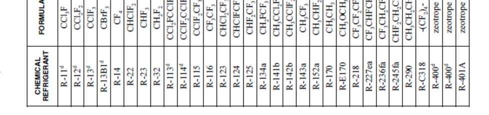
213 4101:

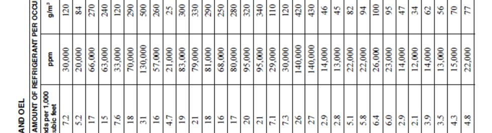

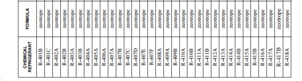
214 4101:
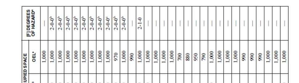


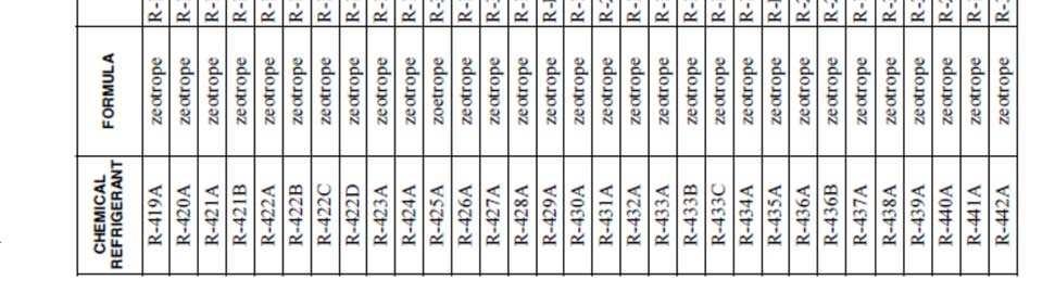
215 4101:


216 4101:
DEFINITIONS CHAPTER 2
 CHAPTER 2 DEFINITIONS SECTION 201 GENERAL 201.1 Scope. Unless otherwise expressly stated, the following words and terms shall, for the purposes of this code, have the meanings indicated in this chapter.
DEFINITIONS CHAPTER 2
 CHAPTER 2 DEFINITIONS SECTION 201 GENERAL 201.1 Scope. Unless otherwise expressly stated, the following words and terms shall, for the purposes of this code, have the meanings indicated in this chapter.
Summary of BBS Proposed Ohio Mechanical Code Rule Changes October 2016
 Summary of BBS Proposed Ohio Mechanical Code Rule Changes October 2016 Ohio Administrative Code Rule Number OMC Section IMC origin Reason for proposed 4101:2-2-01 Air, Makeup 2015 Modified definition Air,
SPECIFIC APPLIANCES, FIREPLACES AND SOLID FUEL-BURNING EQUIPMENT
 CHAPTER 9 SPECIFIC APPLIANCES, FIREPLACES AND SOLID FUEL-BURNING EQUIPMENT SECTION 901 GENERAL 901.1 Scope. This chapter shall govern the approval, design, installation, construction, maintenance, alteration
DEFINITIONS CHAPTER 2
 CHAPTER 2 DEFINITIONS SECTION 201 (IFGC) GENERAL 201.1 Scope. Unless otherwise expressly stated, the following words and terms shall, for the purposes of this code and standard, have the meanings indicated
DEFINITIONS CHAPTER 2 SECTION 201 GENERAL
 CHAPTER 2 DEFINITIONS SECTION 201 GENERAL 201.1 Scope. Unless otherwise expressly stated, the following words and terms shall, for the purposes of this code and standard, have the meanings indicated in
SPECIFIC APPLIANCES, FIREPLACES AND SOLID FUEL-BURNING EQUIPMENT
 CHAPTER 9 SPECIFIC APPLIANCES, FIREPLACES AND SOLID FUEL-BURNING EQUIPMENT SECTION 901 GENERAL 901.1 Scope. This chapter shall govern the approval, design, installation, construction, maintenance, alteration
GASEOUS HYDROGEN SYSTEMS
 CHAPTER 7 GASEOUS HYDROGEN SYSTEMS SECTION 701 GENERAL 701.1 Scope. The installation of gaseous hydrogen systems shall comply with this chapter and Chapters 30 and 35 of the Fire Compressed gases shall
SEMICONDUCTOR FABRICATION FACILITIES
 CHAPTER 18 SECTION 1801 GENERAL 1801.1 Scope. Semiconductor fabrication facilities and comparable research and development areas classified as Group H-5 shall comply with this chapter and the International
CHAPTER 9 SPECIFIC APPLIANCES, FIREPLACES AND SOLID FUEL BURNING EQUIPMENT
 CHAPTER 9 SPECIFIC APPLIANCES, FIREPLACES AND SOLID FUEL BURNING EQUIPMENT SECTION 901 GENERAL 901.1 Scope. This chapter shall govern the approval, design, installation, construction, maintenance, alteration
SEMICONDUCTOR FABRICATION FACILITIES
 CHAPTER 18 SEMICONDUCTOR FABRICATION FACILITIES SECTION 1801 GENERAL 1801.1 Scope. Semiconductor fabrication facilities and comparable research and development areas classified as Group H-5 shall comply
Contents Chapters 4 & 5 of the 2012 Michigan Mechanical Code CHAPTER 4, MMC: VENTILATION CHAPTER 5, MMC: EXHAUST SYSTEMS
 Contents Chapters 4 & 5 of the 2012 Michigan Mechanical Code CHAPTER 4, MMC: VENTILATION CHAPTER 5, MMC: EXHAUST SYSTEMS 1 Ventilation and Exhaust 2 Seminar Introduction Seminar addresses key concepts
SEMICONDUCTOR FABRICATION FACILITIES
 CHAPTER 18 SEMICONDUCTOR FABRICATION FACILITIES SECTION 1801 GENERAL 1801.1 Scope. Semiconductor fabrication facilities and comparable research and development areas classified as Group H-5 shall comply
LABEL PLEASE NOTE: ALL APPLICATIONS AND SITE PLANS MUST BE COMPLETED IN BLACK OR BLUE INK ONLY
 STAFF USE ONLY Thurston County Resource Stewardship 2000 Lakeridge Dr. S.W. Olympia, WA 98502 (360)786-5490 / (360)754-2939 (Fax) TDD Line (360) 754-2933 Email: permit@co.thurston.wa.us www.co.thurston.wa.us/permitting
MECHANICAL EXHAUST VENTILATION SYSTEMS OPERATIONAL GUIDELINES-REVISED 2003
 MECHANICAL EXHAUST VENTILATION SYSTEMS OPERATIONAL GUIDELINES-REVISED 2003 California Conference of Directors of Environmental Health I. Background Proper venting and capture of the gases, heat, grease,
Ventilation for New Low-Rise Residential Buildings July 20, 2015
 Ventilation for New Low-Rise Residential Buildings July 20, 2015 BSC Standard 01 2015 Building Science Corporation 3 Lan Drive, Suite 102 Westford, MA 01886 www.buildingscience.com Contents 1. PURPOSE...3
SEMICONDUCTOR FABRICATION FACILITIES
 CHAPTER 18 SEMICONDUCTOR FABRICATION FACILITIES SECTION FC 1801 GENERAL 1801.1 Scope. This chapter shall govern the design, installation, operation and maintenance of semiconductor fabrication facilities
Part VI Fuel Gas FUEL GAS CHAPTER 24
 Part VI Fuel Gas CHAPTER 24 FUEL GAS The text of this chapter is extracted from the 2009 edition of the International Fuel Gas Code and has been modified where necessary to conform to the scope of application
Analysis of Changes for the 6 th Edition (2017) Florida Codes
 Florida Codes") Analysis of Changes for the 6 th Edition (2017) Florida Codes Changes to the Florida Building Code, Mechanical This Analysis of Changes for the 6 th Edition (2017) of the Florida Codes is intended to provide
Analysis of Changes for the 6 th Edition (2017) Florida Codes Changes to the Florida Building Code, Mechanical This Analysis of Changes for the 6 th Edition (2017) of the Florida Codes is intended to provide
CHAPTER 5: EXHAUST SYSTEMS
 MOTORS, FANS AND FILTERS 503.1 General. Motors and fans shall be sized to provide the required air movement. Motors in areas that contain flammable vapors or dusts shall be of a type approved for such
2012 ICC Commercial Kitchen Hoods
 Welcome 2012 ICC Commercial Cooking Hoods Based on the: 2012 International Mechanical Code (IMC ) 2012 International Fire Code (IFC ) 2012 International Fuel Gas Code, (IFGC ) 2012 International Building
CHAPTER 2 DEFINITIONS
 CHAPTER 2 DEFINITIONS 201.0 General. 201.1 Applicability. For the purpose of this code, certain abbreviations, terms, phrases, words, and their derivatives shall be construed as specified in this chapter.
Part VI Fuel Gas FUEL GAS > > > > > CHAPTER 24
 Part VI Fuel Gas CHAPTER 24 FUEL GAS SECTION G2401 GENERAL G2401.1 Application. This chapter covers those fuel- gas piping systems, fuel-gas utilization equipment and related accessories, venting systems
Gil Rossmiller. In the construction industry for over 30 years. ICC IRC Plumbing & Mechanical Code Development Committee
 Gil Rossmiller In the construction industry for over 30 years ICC IRC Plumbing & Mechanical Code Development Committee ICC- IECC Commercial Energy Code Development Committee Building Official Parker, Colorado
1. PURPOSE This standard specifies safe design, construction, installation, and operation of refrigeration systems.
 ants. Over the next 11 years, representatives from the American Gas Association, American Institute of Electrical Engineers, American Institute of Refrigeration, American Chemical Society, American Society
TABLE OF CONTENTS. Part I Administrative... 1
 Part I Administrative............................ 1 CHAPTER 1 Deleted Part II Definitions.............................. 3 CHAPTER 2 DEFINITIONS.................... 3 R201 General..................................
2012 INTERNATIONAL FUEL GAS CODE VENTS
 2012 INTERNATIONAL FUEL GAS CODE SECTION 502 (IFGC) VENTS 502.1 General. All vents, except as provided in Section 503.7, shall be listed and labeled. Type B and BW vents shall be tested in accordance with
Inspection Checklist Mechanical Rough in
 Property Owner Name: Property Address: Permit Number: Inspectors Name: Review Date: Permits and Plans 1. Job address is posted in a visible location. (R319.1) 2. Permit and approved plans are on site and
CHAPTER 2 DEFINITIONS. AIR, OUTSIDE is air from outside the building. AIR, RETURN is air from the conditioned area that is
 CHAPTER 2 DEFINITIONS 201.0 General. For the purpose of this code, certain abbreviations, terms, phrases, words, and their derivatives shall be construed as specified in this chapter. Words used in the
Lombard Fire Department Bureau of Fire Prevention COMMERCIAL HOOD & DUCT SYSTEMS
 Lombard Fire Department Bureau of Fire Prevention COMMERCIAL HOOD & DUCT SYSTEMS (630) 620-5750 Fax: (630) 629-2374 www.villageoflombard.org COMMERCIAL HOOD & DUCT SYSTEM PLAN REVIEW REQUIREMENTS International
SPECIFIC APPLIANCES CHAPTER 6
 CHAPTER 6 SPECIFIC APPLIANCES SECTION FGC 601 GENERAL 601.1 Scope. This chapter shall govern the approval, design, installation, construction, maintenance, alteration and repair of the appliances and equipment
IMC Significant Changes Summary Tier I
 2009-2015 IMC Significant Changes Summary Tier I 202 Environmental Air The definition of environmental air has been expanded through the addition of parking garage exhaust. 306.1 Access More than just
CHAPTER LOCAL AMENDMENTS TO THE INTERNATIONAL MECHANICAL CODE 2000 EDITION
 CHAPTER 23.20 LOCAL AMENDMENTS TO THE INTERNATIONAL MECHANICAL CODE 2000 EDITION SECTIONS 23.20.100 Local Amendments To The International Mechanical Code, 2000 Edition 23.20.202 Definitions 23.20.301.14
TABLE OF CONTENTS. Part I Administrative... 1
 Part I Administrative............................ 1 CHAPTER 1 ADMINISTRATION............... 1 R101 Title, Scope and Purpose.................... 1 R102 Applicability.............................. 1 R103
1 Exam Prep Florida Building Code-Mechanical Tabs and Highlights
 1 Exam Prep Florida Building Code-Mechanical Tabs and s These 1 Exam Prep Tabs are based on Florida Building Code-Mechanical, 2014. Each 1 Exam Prep tabs sheet has five rows of tabs. Start with the first
Laboratories and Hazardous Materials. Company Overview
 Laboratories and Hazardous Materials Don E. Contois, P.E. Sam Sinapi Company Overview R.W. Sullivan Engineering (RWS) was established in 1945 and currently has 95 employees. RWS is a full service engineering
SPECIFIC APPLIANCES CHAPTER 6
 CHAPTER 6 SPECIFIC APPLIANCES SECTION 601 GENERAL 601.1 Scope. This chapter shall govern the approval, design, installation, construction, maintenance, alteration and repair of the appliances and equipment
2015 ICC Commercial Cooking Systems
 2015 ICC Commercial Cooking Systems Based on the: 2015 International Building Code (IBC ) 2015 International Mechanical Code (IMC ) 2015 International Fire Code (IFC ) 2015 International Fuel Gas Code
UNIFORM MECHANICAL CODE
 INDEX Note: Content and section numbers will be updated before publishing. 2009 International Association of Plumbing and Mechanical Officials. All rights reserved. The copyright in this index is separate
COMMERCIAL KITCHEN SUPPRESSION SYSTEMS INFORMATION PACKET
 COMMERCIAL KITCHEN SUPPRESSION SYSTEMS INFORMATION PACKET Colorado Springs Fire Department Division of the Fire Marshal October 2013 Table of Contents PURPOSE... 3 SCOPE... 3 DEFINITIONS... 3 GUIDELINES...
2015 MECHANICAL CODE REQUIREMENTS
 2015 MECHANICAL CODE REQUIREMENTS ANTRIM COUNTY BUILDING DEPARTMENT PO BOX 188 205 CAYUGA STREET BELLAIRE, MI 49615 (231) 533-8373 FAX (231) 533-6041 Mechanical requirements for residential buildings per
***DRAFT - NOT FOR FILING***
 ACTION: Original ***DRAFT - NOT FOR FILING*** DATE: 09/29/2017 1:14 PM 1301:7-7-27 Semiconductor fabrication facilities. (A) Section 2701 General (1) 2701.1 Scope. Semiconductor fabrication facilities
TABLE OF CONTENTS. Part I Administrative
 Part I Administrative.......................... 1-1 CHAPTER 1 SCOPE AND ADMINISTRATION. 1-1 R101 General............................. 1-1 R102 Applicability......................... 1-2 R103 (Not adopted)........................
CHAPTER 7 ALTERATIONS LEVEL
 CHAPTER 7 ALTERATIONS LEVEL 2 SECTION 701 GENERAL 701.1 Scope. Level 2 alterations as described in Section 404 shall comply with the requirements of this chapter. Exception: Buildings in which the reconfiguration
REQUIREMENTS FOR HOOD PLANS
 DEPARTMENT OF PUBLIC HEALTH Division of Environmental Health REQUIREMENTS FOR HOOD PLANS Submit one (1) set of plans drawn to scale of at least ¼-inch per foot. Plans shall conform to applicable California
CHAPTER LOCAL AMENDMENTS TO THE INTERNATIONAL MECHANICAL CODE 2012 EDITION
 CHAPTER 23.20 LOCAL AMENDMENTS TO THE INTERNATIONAL MECHANICAL CODE 2012 EDITION Sections 23.20.100 Local amendments to the International Mechanical Code, 2012 Edition.... 2 23.20.101.2 Scope.... 2 23.20.103-110
CENTRAL STATE HOSPITAL PLAN SAFE USE HANDLING AND STORAGE OF FLAMMABLE AND COMBUSTIBLE LIQUIDS
 Page 1 of 6 CENTRAL STATE HOSPITAL PLAN SUBJECT: SAFE USE HANDLING AND STORAGE OF FLAMMABLE AND COMBUSTIBLE LIQUIDS ANNUAL REVIEW MONTH: RESPONSIBLE FOR REVIEW: APRIL CSH SAFETY DIRECTOR LAST REVISION
Notable Changes in the Mechanical Codes
 Notable Changes in the Mechanical Codes July 2004 The following are some of the changes between the 1997 Uniform Mechanical Code and the 2003 International Mechanical Code(M) and the 2003 International
ARCHIVED. Compliance Document for New Zealand Building Code Clause G4 Ventilation Second Edition. Prepared by the Department of Building and Housing
 Compliance Document for New Zealand Building Code Clause G4 Ventilation Second Edition Prepared by the Department of Building and Housing This Compliance Document is prepared by the Department of Building
By Authority Of THE UNITED STATES OF AMERICA Legally Binding Document
 By Authority Of THE UNITED STATES OF AMERICA Legally Binding Document By the Authority Vested By Part 5 of the United States Code 552(a) and Part 1 of the Code of Regulations 51 the attached document has
CHIMNEYS AND VENTS CHAPTER 8
 CHAPTER 8 CHIMNEYS AND VENTS SECTION 801 GENERAL 801.1 Scope. This chapter shall govern the installation, maintenance, repair and approval of factory-built chimneys, chimney liners, vents and connectors.
CUMULATIVE ANALYSIS OF UNIFORM MECHANICAL CODE CHANGES to 2003
 CUMULATIVE ANALYSIS OF UNIFORM MECHANICAL CODE CHANGES 2000 to 2003 The following pages contain comments regarding the changes to the 2000 edition of the UNIFORM MECHANICAL CODE (UMC ) that were made to
SPECIFIC APPLIANCES CHAPTER 6
 CHAPTER 6 SPECIFIC APPLIANCES SECTION 601 (IFGC) GENERAL 601.1 Scope. This chapter shall govern the approval, design, installation, construction, maintenance, alteration and repair of the appliances and
2015 & 2012 International Mechanical Code Significant Changes and the PA Uniform Construction Code
 2015 & 2012 International Mechanical Code Significant Changes and the PA Uniform Construction Code Welcome! Shawn Strausbaugh Director PMG Technical Resources ICC Government Relations sstrausbaugh@iccsafe.org
GUIDELINES FOR HIGHRISE BUILDING CONSTRUCTION PROJECTS (MECHANICAL VENTILATION)
") GUIDELINES FOR HIGHRISE BUILDING CONSTRUCTION PROJECTS (MECHANICAL VENTILATION) February, 2017 Contents Clauses Page 1. Basic Concepts 1 2. Design Considerations 1 3. Car Parks Ventilation 2 4. Kitchen
GUIDELINES FOR HIGHRISE BUILDING CONSTRUCTION PROJECTS (MECHANICAL VENTILATION) February, 2017 Contents Clauses Page 1. Basic Concepts 1 2. Design Considerations 1 3. Car Parks Ventilation 2 4. Kitchen
Chapter FUEL GAS CODE*
 Chapter 19.09 FUEL GAS CODE* * Editors Note: Serial No. 2004-31, 1, adopted Oct. 11, 2004 amended Title 19 in its entirety to read as herein set out. See the editor's note at Tit. 19 and also the Code
CHAPTER 2 DEFINITIONS
 CHAPTER 2 DEFINITIONS SECTION 201 (IFGC) GENERAL 201.1 Scope. Unless otherwise expressly stated, the following words and terms shall, for the purposes of this code and standard, have the meanings indicated
CHAPTER 8 CHIMNEYS AND VENTS
 CHAPTER 8 CHIMNEYS AND VENTS SECTION 801 GENERAL 801.1 Scope. This chapter shall govern the installation, maintenance, repair and approval of factory-built chimneys, chimney liners, vents and connectors.
Inspection Checklist Residential Mechanical Rough In July 2016
 Inspection Checklist Residential Mechanical Rough In July 2016 This Inspection Checklist reflects code requirements of the 2015 International Residential Code (IRC), the 2015 Uniform Plumbing Code (UPC),
Appendix 13. Categories of Cooling and Heating systems
 EcoShopping - Energy efficient & Cost competitive retrofitting solutions for Shopping buildings Co-funded by the European Commission within the 7 th Framework Programme. Grant Agreement no: 609180. 2013-09-01
NFPA 33 Standard for Spray Applica4on Using Flammable or Combus4ble Materials
 NFPA 33 Standard for Spray Applica4on Using Flammable or Combus4ble Materials Fire Preven4on Officers Associa4on of Bri4sh Columbia 2013 Annual Seminar Kelowna, Bri4sh Columbia May 9, 2013 NFPA 33 Scope
ARTICLE 25. FUEL GAS CODE
 ARTICLE 25. Rule 1. Indiana Fuel Gas Code, 2003 Edition (Repealed) (Repealed by Fire Prevention and Building Safety Commission; filed Mar 18, 2008, 2:32 p.m.: 20080423-IR-675070479FRA, eff 90 days after
Ordinance No WHEREAS, some provisions within Chapter conflict or contradict the proposed administrative provisions in Chapter 15.
 Ordinance No. 5899 AN ORDINANCE INCORPORATING CHANGES TO THE ADMINISTRATION OF TITLE 15 BUILDINGS AND CONSTRUCTION BY AMENDING CERTAIN PARTS OF THE RAPID CITY MECHANICAL CODE IN CHAPTER 15.26 OF THE RAPID
Gas-fired water heaters, volume III, storage water heaters with input ratings above 75,000 Btu per hour, circulating and instantaneous
 IAS Accreditation Number Company Name Address TL-657 Room 209, No. 46, Nanxiang 3 rd Road Science City Development Zone Guangzhou 510663 People s Republic of China Javen Xuan, Quality Manager Contact Name
CHAPTER 8 CHIMNEYS AND VENTS
 CHAPTER 8 CHIMNEYS AND VENTS SECTION 801 GENERAL 801.1 Scope. This chapter shall govern the installation, maintenance, repair and approval of factory-built chimneys, chimney liners, vents and connectors.
Adopting Agency BSC SFM. Adopt Entire Chapter X X X X X X X X X X Adopt Entire Chapter as amended (amended sections listed below)
") CALIFORNIA MECANICAL CODE MATRIX ADOPTION TABLE CAPTER CIMNEY AND VENTS Adopting Agency BSC SFM CD DSA OSPD 1 1/AC AC SS SS/CC 1 4 Adopt Entire Chapter X X X X X X X X X X Adopt Entire Chapter as amended
CALIFORNIA MECANICAL CODE MATRIX ADOPTION TABLE CAPTER CIMNEY AND VENTS Adopting Agency BSC SFM CD DSA OSPD 1 1/AC AC SS SS/CC 1 4 Adopt Entire Chapter X X X X X X X X X X Adopt Entire Chapter as amended
The Art of Building Science
 The Art of Building Science What is Building Science? Building Science seeks to apply the scientific fundamentals of building dynamics to the functional relationships between the house s components and
Riverside County Fire Department Office of the Fire Marshal Market St., Ste. 150, Riverside, CA Ph. (951) Fax (951)
 Fax (951)") Riverside County Fire Department Office of the Fire Marshal 2300 Market St., Ste. 150, Riverside, CA 92501 Ph. (951) 955-4777 Fax (951) 955-4886 Technical Policy Title: Plant Processing and Extraction
Riverside County Fire Department Office of the Fire Marshal 2300 Market St., Ste. 150, Riverside, CA 92501 Ph. (951) 955-4777 Fax (951) 955-4886 Technical Policy Title: Plant Processing and Extraction
Commercial Kitchen Exhaust Requirements Kitchen Exhaust for Food Service Operations
 Commercial Kitchen Exhaust Requirements Kitchen Exhaust for Food Service Operations District of Lake Country 10150 Bottom Wood Lake Road Lake Country, BC V4V 2M1 t: 250-766-6675 f: 250-766-0200 Inspection
DUCT SYSTEMS CHAPTER 6
 SECTION 601 GENERAL 601.1 Scope. Duct systems used for the movement of air in air-conditioning, heating, ventilating and exhaust systems shall conform to the provisions of this chapter except as otherwise
CHAPTER 6 SPECIFIC APPLIANCES
 CHAPTER SPECIFIC APPLIANCES SECTION 01 (IFGC) GENERAL 01.1 Scope. This chapter shall govern the approval, design, installation, construction, maintenance, alteration and repair of the appliances and equipment
This standard shall prescribe provisions based on minimum requirements for safety to life and property.
 NFPA STANDARDS DEVELOPMENT SITE FIRST DRAFT REPORT Closing Date: February 22, 2013 NOTE: All Public Comment must be received by 5:00 pm EST/EDST on the published Closing Date. NFPA 90B, Standard for the
CHAPTER 10 STEAM AND HOT WATER BOILERS
 CHAPTER 10 STEAM AND HOT WATER BOILERS 1001.0 Purpose. The purpose of this chapter is to establish and provide minimum standards for the protection of public welfare, health, safety, and property by regulating
IFGC-2012 AMENDED IFGC-2015 IFGC-2018 CHAPTER 1 SCOPE AND
 CHAPTER 1 SCOPE AND CHAPTER 1 SCOPE AND ADMINISTRATION ADMINISTRATION 301.1.2 LP-Gas installations. Whenever there is a conflict between this code and NFPA 54 and B+NFOA 58 as adopted by the Nevada LP-Gas
COMBUSTION APPLIANCE SAFETY INSPECTION FOR VENTED APPLIANCES*
 COMBUSTION APPLIANCE SAFETY INSPECTION FOR VENTED APPLIANCES* *Vented appliances refer to natural draft appliances equipped with a barometric draft regulator or Category I appliances equipped with a draft
DUCT SYSTEMS CHAPTER 6
 CHAPTER 6 DUCT SYSTEMS SECTION 601 GENERAL 601.1 Scope. Duct systems used for the movement of air in air-conditioning, heating, ventilating and exhaust systems shall conform to the provisions of this chapter
Fundamentals of the 2012 International Mechanical Code
 Fundamentals of the 2012 International Mechanical Code Brent Ursenbach Salt Lake County PDS 385-468-6694 bursenbach@slco.org bursenbach@yahoo.com 2 IMC 101.2 Scope This code shall regulate the design,
Use of energy recovery systems in air conditioning, ventilation or screening
 CPC - F24F - 2018.08 F24F AIR-CONDITIONING; AIR-HUMIDIFICATION; VENTILATION; USE OF AIR CURRENTS FOR SCREENING (removing dirt or fumes from areas where they are produced B08B 15/00; vertical ducts for
Chapter 101 OPEN FIRES
 Chapter 101 OPEN FIRES 101.1. Definitions: 101.2. General Prohibition Against Open Burning: 101.3. Permitted Fires: 101.4. Authorized Locations: 101.5. Materials: 101.6. Time: 101.7. Prohibition Against
2009 IPC ,IMC Q &A ANDIFGC
 2009 IPC,IMC ANDIFGC Q &A TABLE OF CONTENTS PREFACE.... ix ABOUT THE INTERNATIONAL CODE COUNCIL...x IPC CHAPTER 1 SCOPE AND ADMINISTRATION...1 Section 101 General... 1 Section 102 Applicability... 1 Section
101 S. George St 116 E Gas Ave York, PA York, PA (717) (717)
 (717)") City of York Qdot Engineering 101 S. George St 116 E Gas Ave York, PA 17405 York, PA 17405 (717) 849-2329 (717) 744-8315 INSPECTION CHECKLIST Residential Mechanical 2009 Codes This checklist is intended
City of York Qdot Engineering 101 S. George St 116 E Gas Ave York, PA 17405 York, PA 17405 (717) 849-2329 (717) 744-8315 INSPECTION CHECKLIST Residential Mechanical 2009 Codes This checklist is intended
PROPOSED CODE CHANGES FOR REVIEW BY THE FIRE CODE ACTION COMMITTEE
 PROPOSED CODE CHANGES FOR REVIEW BY THE FIRE CODE ACTION COMMITTEE Developed by the Midwestern Regional Work Group CONTENTS Item 15 Limited area sprinkler systems Item 20 Scope of IFC Ch 7 Item 21 Fire-resistance-rated
BUILDING/FIRE CODE REFERENCES 2006 EDITION
 BUILDING/FIRE CODE REFERENCES 2006 EDITION This document provides a cross reference with the International Building Code and NFPA 1/Uniform Fire The IBC references the IFC in 97 Code sections. This document
SAFETY AND INSTALLATION MANUAL MODEL 8100
 SAFETY AND INSTALLATION MANUAL ENERGY RECOVERY VENTILATORS MODEL 8100 Provides year-round fresh air Recovers 77% of the apparent heating or cooling energy from the exhausted air See Warnings Page 3 Table
Chapter One Commercial Kitchen Fires
 Table of Contents Table of Contents Chapter One Commercial Kitchen Fires COMMERCIAL KITCHEN FIRES... 2 The Commercial Kitchen Fire Problem... 2 Unreported Fires... 2 Cooking By-Products... 3 Grease Accumulation
Adv. 8.4 Guidelines for Biosafety Cabinets Rev
 UNIVERSITY OF CINCINNATI Environmental University Health Services 556-4968 Health and Safety ADVISORY NO. 8.4: GUIDELINES FOR THE SELECTION, INSTALLATION AND USE OF BIOSAFETY CABINETS (INCLUDING ISSUES
(h) Pesticide Application.
 Pesticide Application.") Fire Code Cannabis Amendment Section 13.20.066 is added to the Marysville Municipal Code to read in its entirety as follows: 13.20.066 Cannabis Growing, Processing, or Extraction Facilities (a) Application.
Fire Code Cannabis Amendment Section 13.20.066 is added to the Marysville Municipal Code to read in its entirety as follows: 13.20.066 Cannabis Growing, Processing, or Extraction Facilities (a) Application.
HVAC Equipment Access Equipment Location
 City of Lancaster- Building Department 121 East Chestnut Street, Suite 102, Lancaster, Ohio 43130-3825 (740) 687-6649, Fax (740) 681-5030 Web site: www.ci.lancaster.oh.us/dept/building HVAC Heating, Ventilating,
Inspection Checklist Mechanical Final
 Property Owner Name: Property Address: Property Parcel Number: Inspectors Name: Review Date: Permits and Plans 1. Job address is posted in a visible location. (R319.1) 2. Permit and approved plans, and
Effective ventilation is necessary for the comfort
 NEWS FROM THE NETWORK Understanding Kitchen Ventilation Clearing the Air and Eliminating the Myths by Tom Stroozas CFE, RCGC, CFSP GFEN Consulting Editor Effective ventilation is necessary for the comfort
Part I Extraction Process Equipment
 745 West Colfax Avenue Denver, CO 80204 p: 720.913.3474 f: 720.913.3596 www.denvergov.org/fire MARIJUANA EXTRACTION GUIDELINE FOR COMMERCIAL / LICENSED FACILITIES The information contained within this
Building Department Informational Handout
 City of Sonoma Building Department Informational Handout Residential Water Heaters Handout No: 15 Revised: 4/26/18 A water heater is an appliance designed to supply hot water and is equipped with automatic
CHAPTER 5 WATER HEATERS
 CAPTER WATER EATERS Part I 1. General. The regulations of this chapter shall govern the construction, location, and installation of fuelburning and other water heaters heating potable water, together with
2018 IFC Update. Based on the 2018 International Fire Code, (IFC ) Goal. Objectives. Content
 Goal. Objectives. Content") Based on the 2018 International Fire Code, (IFC ) The International Fire Code (IFC ), establishes minimum regulations for fire safety. This handout will identify important changes in the IFC from 2015
Based on the 2018 International Fire Code, (IFC ) The International Fire Code (IFC ), establishes minimum regulations for fire safety. This handout will identify important changes in the IFC from 2015
Level I Chapter 1 Worksheet
 Chapter 1 Worksheet 1. When the present code requires certain safety to life requirements for existing buildings, those requirements shall. a. be void b. apply c. be approved d. be grand-fathered 2. The
X Article/Section 902.0(D) X X X X X X X X X X X
 X X X X X X X X X X X") CALIFORNIA MECHANICAL CODE MATRIX ADOPTION TABLE CHAPTER 9 INSTALLATION OF SPECIFIC APPLIANCES Adopting Agency BSC SFM HCD DSA OSHPD 1 2 1/AC AC SS SS/CC 1 2 3 4 Adopt Entire Chapter X X X X X Adopt Entire
CALIFORNIA MECHANICAL CODE MATRIX ADOPTION TABLE CHAPTER 9 INSTALLATION OF SPECIFIC APPLIANCES Adopting Agency BSC SFM HCD DSA OSHPD 1 2 1/AC AC SS SS/CC 1 2 3 4 Adopt Entire Chapter X X X X X Adopt Entire
Special Occupancy Requirements
 Special Occupancy Requirements CHAPTER 2 0 AVIATION FACILITIES CHAPTER 2 1 DRY CLEANING CHAPTER 2 2 COMBUSTIBLE DUST-PRODUCING OPERATIONS Special Occupancies The objective of this module is to make the
2012 International Mechanical Code Significant Changes. About the Significant Changes
 Significant Changes to the International Mechanical Code and the International Fuel Gas Code With Louisiana Amendments Copyright Materials This presentation is protected by US and International Copyright
MSYS 4490 AC Systems
 MSYS 4490 AC Systems Winter 2015 KITCHEN VENTILATION SYSTEMS By Satwinder Singh 12/02/2015 1 12/02/2015 2 By Satwinder Singh 1 12/02/2015 3 12/02/2015 4 By Satwinder Singh 2 Type I: Types of Hoods used
Above Ground Fuel Tank Requirements
 FIRE DEPARTMENT in cooperation with Above Ground Fuel Tank Requirements The purpose of this document is to provide information about general Fire Code requirements for above ground storage within the unincorporated