Condensing Unit and Refrigeration System Installation & Operations Manual R448A/R449A
|
|
|
- Randolph Simmons
- 6 years ago
- Views:
Transcription


1 Condensing Unit and Refrigeration System Installation & Operations Manual R448A/R449A REV _BJ
2 TABLE OF CONTENTS INTRODUCTION... WARNING LABELS AND SAFETY INSTRUCTIONS...4 M-SERIES CONDENSING UNIT FEATURES...5 REFRIGERATION MODEL NOMENCLATURE...6 PRE-INSTALLATION...7 General Information...7 Delivery Inspection...7 INSTALLATION INSTRUCTIONS...7 Handling and Placement of Condensing Unit...7 Handling and Placement of Evaporator Coil in Walk-In...8 Electrical...9 Refrigerant Piping...9 Leak Check...0 Evacuation, Dehydration and Start-Up...0 Evacuation Procedure...0 Finish Charging Procedures... Preliminary...0 Remote "M-Series"... Pre-Charged Remote Refrigeration Systems...- Final Check List for All Models...4 SUCTION AND LIQUID LINE SIZES EQUIVALENT LENGTH ALLOWANCE FOR FITTINGS...9 GENERAL INFORMATIONS LOW AMBIENT CHARGE CHART...0 SYSTEM TROUBLESHOOTING CHART UNIT BASE SPECIFICATIONS... SALE AND DISPOSAL... INSTALLATION DATA SHEET...4
3 INTRODUCTION This manual contains important instructions for installation, use and service. Read all of this manual carefully before installing or servicing your refrigeration equipment. NOTICE Installation and service of the refrigeration and electrical components must be performed by a refrigeration mechanic or licensed electrician. The portions of this manual covering refrigeration and electrical components contain technical instructions intended only for persons qualified to perform refrigeration and electrical work. DANGER Equipment MUST be properly grounded. Improper or faulty hook-up of electrical components of the refrigeration units can result in severe injury or death. All electrical wiring hook-ups must be done in accordance with all applicable local, regional or national standards. NOTICE Read this manual before installing your refrigeration. Keep the manual and refer to it before doing any service. Failure to do so could result in personal injury or equipment damage. This manual cannot cover every installation, use or service situation. If you need additional information, contact us at: Parts and Technical Service Department Norlake: Koolstar:
4 WARNING LABELS AND SAFETY INSTRUCTIONS This is the safety-alert symbol. When you see this symbol, be alert to the potential for personal injury or damage to your equipment. Be sure you understand all safety messages and always follow recommended precautions and safe operating practices. NOTICE TO EMPLOYERS You must make sure that everyone who installs uses or services your refrigeration is thoroughly familiar with all safety information and procedures. Important safety information is presented in this section and throughout the manual. The following signal words are used in the warnings and safety messages. DANGER: WARNING: CAUTION: NOTICE: Severe injury or death WILL occur if you ignore the message. Severe injury or death CAN occur if you ignore the message. Minor injury or damage to your refrigeration can occur if you ignore the message. This is important installation, operation or service information. If you ignore the message, you may damage your refrigeration. The warning and safety labels shown throughout this manual are placed on your refrigeration at the factory. Follow all warning label instructions. If any warning or safety labels become lost or damaged, call our parts and technical service department for replacements. This label is located on the condensing unit. 4
5 M-SERIES CONDENSING UNIT FEATURES STANDARD COMPONENTS The M-Series set of standard features (pre-wired and mounted except as noted)* include: Liquid line and suction line vibration absorbers (eliminators) for semi-hermetic units only Preset non-adjustable high pressure control and preset non-adjustable low pressure control** Crankcase heater Head pressure control (flooding valve) Heavy gauge, galvanized steel mechanically-fastened weather hood Suction service valve Heavy-duty angle leg base Liquid line filter/drier Pre-wired electrical control panel Sight glass Liquid and suction line kit with service valve Timer (standard on low temp units only) Compressor contactor Defrost heater contactor (when required) Generously-sized condenser (rated up to 0 ambient) Rifled tubes in condenser for greater efficiency Liquid line shut-off valve for easy change of filter PSC condenser fan motors Large liquid receiver (good for maximum 00 ft. line run) One year limited compressor warranty *Components may vary depending on horsepower and application. Consult our factory for verification of standard and optional components. **Preset high pressure control and preset low pressure control are non-adjustable in medium temp M-Series units. The low pressure control is adjustable in low temp units. OPTIONALLY AVAILABLE Special voltages Insulated and heated receiver (thermostatically controlled) Suction accumulator Coated condenser coils Oil separator Phase loss/low voltage monitor Factory pre-assembled evaporator coil (includes factory pre-mounting of thermostatic air control and expansion valve) Factory pre-charged system with quick connect liquid and suction line sets up to 40 ft. (specify length when ordering) Adjustable low pressure control for medium and high temp units Dual pressure control Circuit breaker Suction filter Fan cycling switch Pre-mounted solenoid at evaporator Liquid line solenoid valve (shipped loose) Timer for medium temp units Extended four years limited compressor warranty Master Controller.0 electronic control system Reverse cycle defrost 5
6 REFRIGERATION MODEL NOMENCLATURE MODEL NUMBER EXPLANATION (CONVENTIONAL = ACCESSIBLE HERMETIC) MH = Hermetic Condensing Unit MS = Scroll Condensing Unit MC = Conventional Condensing Unit ROOM TEMPERATURE EXPLANATION L = 0 F. Thru -0 F. Room Temperature M = 0 Thru +55 F. Room Temperature REFRIGERANT EXPLANATION D = R448A/R449A V = R-407A HORSEPOWER RATING EXPLANATION 005 = ½ H.P. 07 = ¾ H.P. 040 = 4H.P. 00 = 0 H.P. 50 = 5 H.P. 007 = ¾ H.P. 00 = H.P. 045 = 4 /H.P. 0 = H.P. 70 = 7 H.P. 00 = H.P. 05 = ½ H.P. 050 = 5 H.P. 50 = 5 H.P. 00 = 0 H.P. 0 = /4 H.P. 00 = H.P. 060 = 6 H.P. 00 = 0 H.P. 05 = / H.P. 05 = / H.P. 075 = 7 / H.P. 0 = H.P. EQUIPMENT VARIATION EXPLANATION A = STANDARD UNIT H = HEATED AND INSULATED RECEIVER E = ELECTRIC DEFROST M = FLOATING HEAD (MC) R= REVERSING VALVE VOLTAGE EXPLANATION A = 5/60/ F = 00-0/50/ B = 0/60/ or 08-0/60/ (As Applicable) G = 80-40/50/ C = 08-0/60/ J = 80/50/ D = 460/60/ K = 00-0/50/ or 0/50/ E = 460/60/ 6
7 PRE-INSTALLATION INSTRUCTIONS I. General Information Please read this manual prior to installing your equipment. This information is based on good refrigeration practice and should be used as a guide for installation and operation. To complete the installation, please records the data requested on the Installation Data form on the last page of the manual and return this manual to the owner. II. Delivery Inspection You are responsible for filing all freight claims with the delivering truck line. Inspect all cartons and crates for damage as soon as they arrive. If damage is noted to shipping crates, cartons or if a shortage is found; note this on the bill of lading (all copies) prior to signing. If damage is discovered when the cabinet is uncrated, immediately call the delivering truck line and follow up the call with a written report indicating concealed damage to your shipment. Ask for an immediate inspection of your concealed damage item. Crating material MUST be retained to show the inspector from the truck line. INSTALLATION INSTRUCTIONS I. Handling and Placement of Condensing Unit To minimize damage to the unit housing, it is recommended that the crate not be removed until the unit is moved to its final location. The following should be considered when placing the unit: A. The condenser coil (air inlet) should not be located so as to restrict air flow into the coil. A minimum of " is required (8" is preferred) between the face of the coil and a wall or other vertical obstruction. B. A minimum of 6" is required on the sides to allow access to the housing clamps. C. A minimum of 4" is required on the louvered end (air outlet) for clearance when opening housing and for ease of maintenance. D. Do not position multiple units so that the air discharge of one is into the condenser air intake of another. Holes are provided in the base supports for mounting bolts and for bridle lift rods. For indoor mounting, motor rooms should be provided with fans designed to move 000 cfm of air per ton of refrigeration. 7
8 II. Handling and Placement of Evaporator Coil in Walk-In To minimize damage to the evaporator coil, it is recommended that the carton (or crate) not be removed until the evaporator coil is moved close to its final location. When the container is removed from the evaporator coil, extreme care must be used when lifting and mounting to the ceiling, to prevent sheet metal damage. EVAPORATOR INSTALLATION INSTRUCTIONS A. Do not install the evaporator too close to door openings to prevent icing problems. B. Minimum clearance between evaporator and the walls is equal to or greater than the coil height for proper air flow and service access. C. Refer to the evaporator coil drawing dimension for mounting holes location. D. Install washers and secure with nuts. Tighten until the coil is firm against the ceiling. The evaporator coil must be level. EVAPORATOR DRAIN LINE INSTALLATION: 8
9 III. Electrical Electric power supply must match the condensing unit power requirements indicated on the unit data plate. A WIRING DIAGRAM IS LOCATED ON THE INSIDE OF THE ELECTRICAL BOX COVER. All field wiring may enter the holes provided in left side, back and bottom of the electrical box. All field wiring should be done in a professional manner, in accordance with all governing codes. Double check all wiring connections, including factory terminals, before start-up of condensing unit. DANGER Installation of the refrigeration and electrical components must be performed only by a refrigeration mechanic or licensed electrician. Improper or faulty hook-up of electrical components can result in death. IV. Refrigerant Piping The condensing unit must remain sealed and pressurized from the manufacturer until piping is complete and final connections are ready to be made. Use only refrigeration grade copper tubing, (ACR), type "L", bright annealed, dehydrated, and properly sealed against contamination. Soft temper tubing may not be used for field interconnection of refrigeration components (condensing unit to evaporator assembly). Take extreme care to keep refrigeration tubing clean and dry prior to installation. Use an appropriate size tube cutter (DO NOT CUT TUBING WITH A SAW). Note: The liquid line size is determined by conventional piping practices for air and electric defrost (use chart on pages 4-5). For reverse cycle defrost, the liquid line must be selected by choosing the liquid line one nominal step larger than the conventional approach. Suction lines should slope down / inch for each 0 feet of horizontal run towards the compressor. If any portion of the suction line rises above the exit elevation of the evaporator, P-type oil traps should be located at the base of each suction riser for proper oil return to the compressor. When brazing, dry nitrogen MUST be passed through the lines at low pressure to prevent scaling and oxidation inside the tubing and fittings. All flux must be removed from the joints after brazing. MINIMIZE the amount of flux used to prevent internal contamination of the refrigeration system. Silver brazing wire is to be utilized (high temperature alloy of 5% silver content on all copper to copper connections, and high temperature alloy of 45% silver content on all dissimilar metal connections). 9
10 NOTICE Be sure solenoid valves are open before beginning evacuation and leak check. v. Leak Check When all refrigeration line connections have been made, the complete system, including factory connections, should be leak checked. Add the proper refrigerant to 60 psig, then boost to 75 psig with dry nitrogen. Leaks check all joints with an electronic leak detector or a halide torch. If leaks are found, relieve the pressure and make repairs as necessary and recheck. VI. Evacuation, Dehydration and Start-Up A vacuum of 500 microns or less must be pulled to properly dehydrate the system. This requires a two-stage vacuum pump with an electronic vacuum indicator. ***DO NOT USE THE SYSTEM COMPRESSOR AS A VACUUM PUMP. *** ***DO NOT OPERATE COMPRESSOR WHILE SYSTEM IS IN A VACUUM. *** Evacuation Procedure A. Open all condensing unit service valves and relieve system pressure. Also, open any line valves installed in the system and energize all solenoid valves to facilitate evacuation. B. Connect the vacuum pump to the high and low sides of the system using /4" or larger cop per lines or /4" ID hoses with high vacuum designation. C. Leaks or moisture will be indicated if the system pressure rises when the vacuum line is closed off. D. Pull a vacuum of 500 microns, close vacuum line and break vacuum to psig, maximum, with refrigerant to be used in the system. E. Repeat step D. F. A final vacuum of 50 microns should be pulled before charging. When 50 microns is reached, close vacuum line and charge through high side, with proper refrigerant to the level of -/ lbs. per ton of refrigeration. 0
11 Finish Charging Procedures A. Preliminary. Be sure all service valves are open.. Loose the compressor hold-down bolts and remove shipping clips to allow compressor to float freely on the springs.. Check evaporator fan motors after start-up. Medium temperature, air defrosts fans run continuously. Low temperature fans and coolers provided with electric defrost will be delayed by the fan control. 4. Start the system by flipping on the circuit breaker in the unit electric box. 5. Start charging per (B), (C), (D) or (E) on the following pages. CAUTION: Never add liquid refrigerant to the suction side of the compressor. 6. Check operating pressures while charging and on initial pull down to prevent damage if a problem occurs. If system floods back to the compressor, adjust the thermostatic expansion valve as required for proper operation. There should be at least +0 F superheat entering the compressor. 7. Observe compressor amperage draw and compare to compressor nameplate to prevent damage due to high amperage. The oil sight glass should be between / and /4 full during normal operation B. Remote "M-Series" Condensing Units. For models without head pressure control valve: With the system operating, add refrigerant until the sight glass indicates a full charge, then add one pound for each rated horsepower of the condensing unit when charging above +75 F. If ambient is below +75 F, add / to the above. See A.6 above.. For models with head pressure control valve: Add additional charge per the procedure on DANGER Charging of the refrigeration system must be performed only by a certified refrigeration mechanic. Improper or faulty hook-up of refrigeration electrical components can result in injury or death. Technical installation instructions for Pre-Charged Remote Refrigeration are given on the following pages. Installation requirements for other remote refrigeration systems may vary. If additional information is needed, your certified refrigeration mechanic or electrician can call our technical service department.

12 Quick-Couples are pre-charged with the proper refrigerant at the factory. C. Pre-Charged Remote Refrigeration Systems. Place a steel or treated-wood spreader on the top of the walk-in to distribute the load of the coil. The spreader must be at least twice the width of the coil. The coil must be mounted away from the edge of the roof a distance equal to the height of the coil (See Figure #). Uncrate the coil and through-bolt it to the ceiling of the walkin with suitable fasteners. Figure # Quick-Couple Remote Refrigeration Uncrate the condensing unit and locate near coil. Be sure air movement around the unit is not restricted so the condensing unit will have a sufficient supply of air to function properly. NOTE: Install evaporator coil in accordance with the manufacturer's recommendations from inside wall or obstructions to rear of evaporator. Drill holes through the walk-in wall large enough to pass refrigeration lines, electrical line and drain line. Connect liquid and suction lines to the coil and the condensing unit. Lubricate rubber seal in male half of coupling with refrigeration oil. Thread coupling halves together by hand to ensure proper mating of threads. Tighten with wrenches until coupling bodies bottom or a definite resistance is felt (See Figure #.) Figure # Quick-Couple Coupling Detail Using a scribe or ink pen, mark a line lengthwise from the coupling hex to the bulkhead. Then tighten an additional /6 to /4 turn. The misalignment of the mark will show the degree of tightening for future reference. This final turn is necessary to ensure that the knife edge metal seal bites into the brass seat of the coupling halves, forming a leak-proof joint. When routing refrigeration lines, special care should be taken not to kink the lines and restrict the flow of refrigerant. NOTE: Wiring diagrams are located inside the pre-wired electrical panel on the condensing unit. CAUTION Be sure the electrical supply is sufficient for all electrical loads of the quick-couple Remote Refrigeration system.
13 Connect correctly rated over current protection device in the service line to the service line J-box on the condensing unit. After routing condensate line from drain pan of evaporator coil, seal around all refrigeration, electrical and drain lines with silicone or butyl caulking. Start compressor and allow to run at least 4 hours before placing product into the walk-in. During the testing period you should: Check the temperature holding range against the control setting. On low temperature units, check the defrost control system to see that all ice is removed from the coil during each defrosts cycle. Perform checks of door operation and all other component operations. These particular systems are pre-charged at the factory with proper refrigerant, but should be operationally checked as per page, A.6 and A.7.
14 VII. Final Check List for All Models A. Check high-low pressure control settings. B. Check setting of defrost timer:. Medium temperature to 4 defrosts/4 hours, with 5 minutes fail safe.. Low temperature to 4 defrosts/4 hours, with 44 minutes fail safe. C. Check operating pressure. D. Check electrical requirements of unit to power supply voltage. E. Set temperature control for desired temperature range. F. Check setting of thermostatic expansion valve for proper operation. G. Check sight glass for proper refrigerant charge. H. Check compressor oil level. I. Check system for proper defrost settings and operation. J. Check condensing unit for vibrating or rubbing tubing. Dampen or clamp as required. K. Open all valves completely counter clockwise. L. Check packing nuts on all service valves. M. Replace all service valve caps and latch unit covers. 4
15 Liquid Lines Liquid lines should be sized for a minimum pressure drop to prevent flashing. Flashing in the liquid lines would create additional pressure drop and poor expansion valve operation. If a system requires long liquid lines from the receiver to the evaporator or if the liquid has to rise vertically upward any distance, the losses should be calculated to determine whether or not a heat exchanger is required. The use of a suction to liquid heat exchanger may be used to subcool the liquid to prevent flashing. This method of subcooling will normally provide no more than 0 F subcooling on high pressure systems. The amount of subcooling will depend on the design and size of the heat exchanger and on the operating suction and discharge pressures. An additional benefit from the use of the suction to liquid type heat exchanger is that it can help raise the superheat in the suction line to prevent liquid return to the compressor via the suction line. Generally, heat exchangers are not recommended on R- low temperature systems. However, they have proved necessary on short, well insulated suction line runs to provide superheat at the compressor. Refrigerant Piping Install all refrigerant components in accordance with applicable local and national codes and in accordance with good practice for proper system operation. The thermostatic expansion valve must be the externally equalized type. It can be mounted inside the unit end compartment. Mount the expansion valve bulb on a horizontal run of suction line as close as possible to the suction header. Use the clamps provided with the valve to fasten the bulb securely so there is a tight line-to-line contact between the bulb and the suction line. Suction and hot gas connections are made on the outside of the unit. Suction lines should be sloped towards the compressor at the rate of one () inch per ten (0) feet for good oil return. Vertical risers of more than four (4) feet should be trapped at the bottom with a P-trap. If a P-trap is used, the expansion valve bulb should be installed between the unit and the trap. Unit Cooler Piping Pipe size example: Given: -0 F Freezer with one system having () evaporators One condensing unit rated at 4,000 BTUH -0 F SST R404A refrigerant. Two evaporators each rated at,000 BTUH 0 F TD. 00 feet of actual line run between condensing unit to first evaporator and 0 feet of actual line run between the first evaporator and the second evaporator (see figure below). How to figure line sizes:. Determine equivalent line run = actual run + valves and fitting allowances.. Use Line Sizing Tables to size lines.. Note any special considerations. Determine line size (main line from condensing unit):. Main line from the condensing unit to be sized for the total capacity (balance) of the whole system of 4,000 BTUH s (Table 8).. Refer to feet at -0 F SST R404A on the chart. You will find the suction line to be -" and /" liquid line.. Refer to Table 5. For every -" 90 elbow you must add 4 equivalent feet of pipe and.5 equivalent feet of pipe for each - " tee. Therefore, total equivalent line run = Actual line run 00 feet + (6) -" 4' 4 feet + () -" feet Total equivalent line run 6.5 feet 4. Refer to Table 8. For 6.5 total equivalent feet, the suction line size should be -" and the liquid line stays at /" line. Note: The gray shaded areas on Table 8. For 4,000 BTUH s, the maximum suction riser is -" to insure proper oil return and pressure drop from the bottom p-trap to the top p-trap. Evap. Evap. Fittings in this system: (6) 90 elbows in main line plus a 90 turn through a tee. (5) addtional 90 elbows to first evaporator. (4) additional 90 elbows to second evaporator. Determine line size (evaporators):. Line sizing to each evaporator is based on,000 BTUH s and equivalent run from condensing unit. First evaporator has an 05 ft. run and the second evaporator has a 0 ft. run.. Table 8 indicates -" suction for the first evaporator and indicates -" suction for the second evaporator.. Refer to Table 5. Each -" 90 elbow adds equivalent feet of pipe. Each 90 turn through a -" tee adds 6 equivalent feet. 4. Actual line run (evap ) 05 feet + (5) -" ' 5 feet + () 90 turn through 6' 6 feet Total equivalent line run 6 feet Actual line run (evap ) 0 feet + (4) -" ' feet Total equivalent line run feet 5. Table 8 indicates -" suction line and " liquid line from main line to both evaporators. 5
16 Line Sizing The following Tables 7 and 8 indicate liquid lines and suction lines for all condensing units for R-404A, R-507, R-407A/C/F, R-448A and R- 449A When determining the refrigerant line length, be sure to add an allowance for fittings. See Table 5. Total equivalent length of refrigerant lines is the sum of the actual linear footage and the allowance for fittings. Table. Weight of Refrigerants in Copper Lines During Operation (Pounds per 00 lineal feet of type "L" tubing) Line Size O.D. (Inches) / 7/ Refrigerant Liquid Line Hot Gas Line Suction Line at Suction Temperature -40 F -0 F 0 F +0 F +40 F R R-448A/R A R-507, R-404A R R-448A/R A R-507, 404A R R-448A/R A R-507, 404A R R-448A/R A R-507, 404A R R-448A/R A R-507, 404A R R-448A/R A R-507, 404A R R-448A/R A R-507, 404A R R-448A/R A R-507, 404A R R-448A/R A R-507, 404A R R-448A/R A R-507, 404A R R-448A/R A R-507, 404A R R-448A/R A R-507, 404A
17 Table 4. Pressure Loss of Liquid Refrigerants in Liquid Line Risers (Expressed in Pressure Drop, PSIG, and Subcooling Loss, F) Liquid Line Rise in Feet Refrigerant 0' 5' 0' 5' 0' 40' 50' 75' 00' PSIG F PSIG F PSIG F PSIG F PSIG F PSIG F PSIG F PSIG F PSIG F R R-448A,R A R-507, R-404A Based on 0 F liquid temperature at bottom of riser. Table 5. Equivalent Feet of Pipe Due to Valve and Fitting Friction Copper Tube, O.D., Type L / 7/ Globe Valve (Open) Angle Valve (Open) Turn Through Tee Tee (Straight Through) or Sweep Below Elbow or Reducing Tee (Straight Through)
18 Table 6. Recommended Remote Condenser Line Sizes R-407A/C/F, R-448A & R-449A R-507 & R-404A Net Evaporator Total Equiv. Capacity Length Discharge Line (O.D.) Liquid Line Cond. to Discharge Line (O.D.) Liquid Line Cond. to Receiver (O.D.) Receiver (O.D.), , / 00 / / 9, / / 00 / /, / / 00 / 8, / 00 7/8 / 4, / 00 7/8 / 7/8 6, /8 / 7/8 00 7/8 7/8 7/8 48, /8 7/8 00 7/8 7/8-7/8 60, /8 7/8 7/8 00-7/8-7/8 7, /8 7/8-7/8 00-7/ , /8-7/8 00-7/ , / , , , , , , , , , ,080, ,00, ,440, ,680,
19 Table 7. Recommended Line Sizes for R-404A and R507* Suction Line Size Suction Temperature Capacity BTUH +0 F Equivalent Lengths +0 F Equivalent Lengths -0 F Equivalent Lengths -0 F Equivalent Lengths -0 F Equivalent Lengths -40 F Equivalent Lengths Liquid Line Size Receiver to Expansion Valve Equivalent Lengths 5' 50' 00' 50' 5' 50' 00' 50' 5' 50' 00' 50' 5' 50' 00' 50' 5' 50' 00' 50' 5' 50' 00' 50' 5' 50' 00' 50',000 / / / / / / / /,000 / / / / / / / / 7/8 / / 7/8 / / 7/8 4,000 / / / / / 7/8 / 7/8 7/8 7/8 7/8 / 7/8 7/8 6,000 / / 7/8 / / 7/8 / 7/8 7/8 7/8 7/8 7/8 7/8 7/8 7/8 9,000 7/8 7/8 7/8 7/8 7/8 7/8 7/8 7/8 7/8 -,000 7/8 7/8 7/8 7/8 7/8 7/8 7/8 7/8 7/8-7/8 7/ ,000 7/8 7/8 7/8 7/8 7/8 7/8-7/8 7/ /8 7/ ,000 7/8 7/8 7/8-7/8 7/ /8 7/ / ,000 7/8 7/ / / ,000 7/8 7/ / ,000 7/ , , , , , , , , ,000 0, , , , , , , , , /8 7/8-7/8 7/ /8 7/ / /8 7/8-7/8 7/ /8 7/ / * NOTES:. Sizes that are highlighted indicate maximum suction line sizes that should be used for risers. Riser size should not exceed horizontal size. Properly placed suction traps must also be used for adequate oil return. All sizes shown are for O.D. Type L copper tubing.. Suction line sizes selected at pressure drop equivalent to F. Reduce estimate of system capacity accordingly.. Recommended liquid line size may increase with reverse cycle hot gas systems. 4. If system load drops below 40% of design, consideration to installing double suction risers should be made. / / / / / / / / / / / / / / / / / / / / / / / / 7/8 7/8 7/8 7/8 7/8 7/8 7/8 7/8 7/8 7/8 7/8-7/8 7/ /8 7/ /
20 Table 8. Recommended Line Sizes for R-407* Capacity BTUH +40 F Equivalent Lengths Suction Line Size Suction Temperature +0 F Equivalent Lengths +0 F Equivalent Lengths Liquid Line Size Receiver to Expansion Valve Equivalent Lengths 5' 50' 75' 00' 50' 00' 5' 50' 75' 00' 50' 00' 5' 50' 75' 00' 50' 00' 5' 50' 75' 00' 50' 00',000,000 / / / / / / / / / 4,000 / / / / / / / / / 6,000 / / / / / / / / 9,000 / / / 7/8 7/8 7/8 / 7/8 7/8 7/8,000 / 7/8 7/8 7/8 7/8 7/8 7/8 7/8 7/8 7/8 7/8 7/8 7/8 5,000 7/8 7/8 7/8 7/8 7/8 7/8 7/8 7/8 7/8 7/8 7/8 7/8 7/8 7/8 8,000 7/8 7/8 7/8 7/8 7/8 7/8 7/8 7/8 7/8 7/8 7/8 7/8 7/8 7/8 4,000 7/8 7/8 7/8 7/8 7/8 7/8 7/8 7/8 7/8 0,000 7/8 7/8 7/8 7/8 6,000 7/8 7/8 7/8 4,000 7/8 7/8 48,000 7/8 7/8 54,000 7/8 60,000 7/8 66,000 7/8 7,000 7/8 78,000 7/8 84,000 90,000 0,000 50,000 80,000 0,000 40,000 00,000 60, , ,000 7/8 7/8 7/8 7/8 7/8 7/8 7/8 7/8 7/8 7/8 7/8 7/8 7/8 7/8 * NOTES:. Sizes that are highlighted indicate maximum suction line sizes that should be used for risers. Riser size should not exceed horizontal size. Properly placed suction traps must also be used for adequate oil return. All sizes shown are for O.D. Type L copper tubing.. Suction line sizes selected at pressure drop equivalent to F. Reduce estimate of system capacity accordingly.. Recommended liquid line size may increase with reverse cycle hot gas systems. 4. If system load drops below 40% of design, consideration to installing double suction risers should be made. 7/8 7/8 7/8 / / / / / / / / / / / / / / / / / / / / / / / / / 7/8 / 7/8 / 7/8 7/8 / 7/8 7/8 / 7/8 7/8 7/8 7/8 7/8 7/8 7/8 7/8 7/8 7/8 7/8 7/8 7/8 7/8 7/8 7/8 7/8 7/8 7/8 7/8 7/8 7/8 7/8 7/8 7/8 7/8 7/8 7/8 6
21 Table 9. Recommended Line Sizes for R-448A/R-449A* Capacity BTUH +0 F Equivalent Lengths Suction Line Size Suction Temperature +0 F Equivalent Lengths -0 F Equivalent Lengths -0 F Equivalent Lengths 5' 50' 75' 00' 50' 00' 5' 50' 75' 00' 50' 00' 5' 50' 75' 00' 50' 00' 5' 50' 75' 00' 50' 00',000 / / / / / / / /,000 / / / / / / / / 7/8 / / 7/8 7/8 4,000 / / / / / / 7/8 / 7/8 7/8 / 7/8 7/8 7/8 6,000 / / 7/8 7/8 / / 7/8 7/8 / 7/8 7/8 7/8 7/8 7/8 7/8 7/8 9,000 7/8 7/8 7/8 7/8 7/8 7/8 7/8 7/8 7/8 7/8 7/8 7/8 7/8 7/8 7/8,000 7/8 7/8 7/8 7/8 7/8 7/8 7/8 7/8 7/8 7/8 7/8 7/8 7/8 7/8 7/8 7/8 5,000 7/8 7/8 7/8 7/8 7/8 7/8 7/8 7/8 7/8 7/8 7/8 7/8 7/8 8,000 7/8 7/8 7/8 7/8 7/8 7/8 7/8 7/8 7/8 7/8 4,000 7/8 7/8 7/8 7/8 7/8 0,000 7/8 7/8 7/8 6,000 7/8 4,000 /8 48,000 54,000 60,000 66,000 7,000 78,000 84,000 90,000 0,000 50,000 80,000 0,000 40,000 00,000 60, , ,000 * NOTES:. Sizes that are highlighted indicate maximum suction line sizes that should be used for risers. Riser size should not exceed horizontal size. Properly placed suction traps must also be used for adequate oil return. All sizes shown are for O.D. Type L copper tubing.. Suction line sizes selected at pressure drop equivalent to F. Reduce estimate of system capacity accordingly.. Recommended liquid line size may increase with reverse cycle hot gas systems. 4. If system load drops below 40% of design, consideration to installing double suction risers should be made
22 Table 9a.Recommended Line Sizes for R-448A/R-449A* Capacity BTUH Suction Line Size Suction Temperature -0 F Equivalent Lengths -40 F Equivalent Lengths Liquid Line Size Receiver to Expansion Valve Equivalent Lengths 5' 50' 75' 00' 50' 00' 5' 50' 75' 00' 50' 00' 5' 50' 75' 00' 50' 00',000 / / / / / /,000 / / 7/8 7/8 / / 7/8 7/8 4,000 7/8 7/8 7/8 / 7/8 7/8 7/8 6,000 7/8 7/8 7/8 7/8 7/8 7/8 7/8 9,000 7/8 7/8 7/8 7/8 7/8 7/8,000 7/8 7/8 7/8 7/8 7/8 7/8 5,000 7/8 7/8 7/8 7/8 / 8,000 7/8 7/8 / / 4,000 / / / / 0,000 / / / / 6,000 / / / / / 4,000 / / / / 48,000 / / / / / 54,000 / / / / 60,000 / / / 66,000 / / 7,000 / / 78,000 / / 7/8 84,000 / 7/8 90,000 / 7/8 7/8 0,000 7/8 7/8 7/8 50,000 7/8 7/8 7/8 7/8 7/8 80,000 7/8 7/8 7/8 7/8 0,000 7/8 7/8 7/8 7/8 7/8 40,000 7/8 7/8 7/8 7/8 00, /8 7/8 60, /8 7/8 480, , * NOTES:. Sizes that are highlighted indicate maximum suction line sizes that should be used for risers. Riser size should not exceed horizontal size. Properly placed suction traps must also be used for adequate oil return. All sizes shown are for O.D. Type L copper tubing.. Suction line sizes selected at pressure drop equivalent to F. Reduce estimate of system capacity accordingly.. Recommended liquid line size may increase with reverse cycle hot gas systems. 4. If system load drops below 40% of design, consideration to installing double suction risers should be made. 8
23 EQUIVALENT LENGTH ALLOWANCE FOR FITTINGS EQUIVALENT LENGTH IN FEET FITTING Tee Tee SIZE Ell Ell (Line) (Branch) Chart A /" " /8" " " " " GENERAL:. Suction lines should be pitched down in direction of flow, /" per 0 feet of line.. Refrigerant lines should be supported and fastened properly to prevent leaks and for professional looking installation. Supports should be every 5 feet for lines to 7/8" OD, 7 feet for -" to -" OD lines, and 0 feet for -" and -" OD lines.. Where condensation dripping would be objectionable, insulate suction lines, and where the sun could adversely affect performance, insulate both the liquid and suction lines. Insulation thickness of /" will usually be adequate. 4. A P trap must be installed at the bottom of the riser in all vertical suction lines rising 4" or more. To insure proper oil return to the condensing unit, the trap should be the same size as the horizontal line and the riser should be sized per the line sizing charts on pages 4-7. In installations where condensate can accumulate on the vibrasorber, a covering of heat shrink PVC tubing or waterproof tape may be used to prevent freezing under the ferrule, causing a rupture.
24 0
25 System Troubleshooting Chart PROBLEM POSSIBLE CAUSES POSSIBLE CORRECTIVE STEPS Compressor will not run. Main switch open.. Close switch.. Fuse blown.. Check electrical circuits and motor winding for shorts or grounds.. Thermal overloads tripped. Investigate for possible overloading. Replace fuse after fault is corrected. 4. Defective contactor or coil.. Overloads are automatically reset. Check unit closely when unit 5. System shut down by safety devices. comes back on line. 6. No cooling required. 4. Repair or replace. 7. Liquid line solenoid will not open. 5. Determine type and cause of shutdown and correct it before 8. Motor electrical trouble. resetting safety switch. 9. Loose wiring. 6. None. Wait until calls for cooling. 0. Phase loss monitor inoperative. 7. Repair or replace coil. 8. Check motor for open windings, short circuit or burn out. 9. Check all wire junctions. Tighten all terminal screws. Compressor noisy or. Flooding of refrigerant into crankcase.. Check setting of expansion valves. vibrating. Improper piping support on suction or liquid line.. Relocate, add or remove hangers.. Worn compressor.. Replace. 4. Scroll compressor rotation reversed. 4. Rewire for phase change. High discharge. Non-condensables in system.. Remove the non-condensables. pressure. System overcharges with refrigerant.. Remove excess.. Discharge shutoff valve partially closed.. Open valve. 4. Fan not running. 4. Check electrical circuit. 5. Head pressure control setting. 5. Adjust. 6. Dirty condenser coil. 6. Clean. Low discharge. Faulty condenser temperature regulation.. Check condenser control operation. pressure. Suction shutoff valve partially closed.. Open valve.. Insufficient refrigerant in system.. Check for leaks. Repair and add charge. 4. Low suction pressure. 4. See corrective steps for low suction pressure. 5. Variable head pressure valve. 5. Check valve setting. High suction. Excessive load.. Reduce load or add additional equipment. pressure. Expansion valve overfeeding.. Check remote bulb. Regulate superheat. Low suction pressure. Lack of refrigerant.. Check for leaks. Repair and add charge.. Evaporator dirty or iced.. Clean.. Clogged liquid line filter drier.. Replace cartridge(s). 4. Clogged suction line or compressor suction gas strainers. 4. Clean strainers. 5. Expansion valve malfunctioning. 5. Check and reset for proper superheat. 6. Condensing temperature too low. 6. Check means for regulating condensing temperature. 7. Improper TXV. 7. Check for proper sizing. Little or no oil. Clogged suction oil strainer.. Clean. pressure. Excessive liquid in crankcase.. Check crankcase heater. Reset expansion valve for higher superheat.. Low oil pressure safety switch defective. Check liquid line solenoid valve operation. 4. Worn oil pump.. Replace. 5. Oil pump reversing gear stuck in wrong position. 4. Replace. 6. Worn bearings. 5. Reverse direction of compressor rotation. 7. Low oil level. 6. Replace compressor. 8. Loose fitting on oil lines. 7. Add oil and/or through defrost. 9. Pump housing gasket leaks. 8. Check and tighten system. 9. Replace gasket. Compressor loses oil. Lack of refrigerant.. Check for leaks and repair. Add refrigerant.. Excessive compression ring blow by.. Replace compressor.. Refrigerant flood back.. Maintain proper superheat at compressor. 4. Improper piping or traps. 4. Correct piping. Compressor thermal. Operating beyond design conditions.. Add components to bring conditions within acceptable limits (i.e., protector switch. Discharge valve partially shut. CPR/EPR valves, additional condenser surface, liquid injection, etc.). open. Blown valve plate gasket.. Open valve. 4. Dirty condenser coil.. Replace gasket. 5. Overcharged system. 4. Clean coil. 5. Reduce charge.
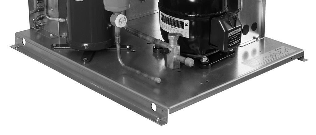
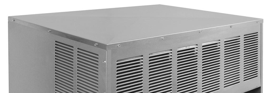
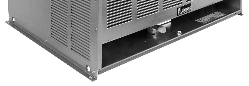
26 UNIT BASE SPECIFICATIONS
27 SALE AND DISPOSAL If you sell or give away your walk-in refrigeration system or components you must make sure that all safety labels and the Refrigeration Unit Installation and Operations Manual are included. If you need replacement labels or manuals, contact the parts and technical service department. The customer service department should be contacted at the time of sale or disposal of your walk-in so records may be kept of its new location. If you sell or give away your Unit and you evacuate the refrigerant charge before shipment, you must evacuate the refrigerant into an approved recovery and reclaim system in order to satisfy all applicable federal and state regulations regarding release of refrigerant compounds into the atmosphere. The release of refrigerant compounds into the atmosphere is a source of ozone depletion and regulated by federal and state law.
28 INSTALLATION DATA Date System Installed Installer and Address Phone: Condensing Unit Model Serial Electrical Volts Phase Evaporator(s) Quantity Model Serial Thermostat Setting F Defrost Setting /4 hrs. Min. Fail Safe Electrical Volts Amps Operating Pressures Suction Discharge 4 Standex International, Inc. Printed in U.S.A.
PARALLEL RACK SYSTEM INSTALLATION & OPERATIONS MANUAL With Master Rack Compressor Sequencer
 PARALLEL RACK SYSTEM INSTALLATION & OPERATIONS MANUAL With Master Rack Compressor Sequencer 5/16 Rev. A 57-02509 2 Contents INTRODUCTION... 4 WARNING LABELS AND SAFETY INSTRUCTIONS... 5 PS SERIES PARALLEL
Condensing Unit Installation and Operating Instructions
 Bulletin WCU_O&I 01 June 2003 Condensing Unit Installation and Operating Instructions WCU Air Cooled Condensing Unit Table of Contents Section 1. Section 2. Section 3. Section 4. Section 5. Section 6.
Condensing Unit Installation and Operating Instructions
 Bulletin ACU_O&I 02 August 2016 Condensing Unit Installation and Operating Instructions ACU Air Cooled Condensers Table of Contents Section 1. General Information... 2 Section 2. Refrigeration Piping...
BLG-HGP Model Bottom Mounted Full-Length Swing Glass Door Freezer Merchandisers
 Installation & Operations Manual for BLG-HGP Model Bottom Mounted Full-Length Swing Glass Door Freezer Merchandisers 2 TABLE OF CONTENTS INTRODUCTION..... 4 STORE CONDITIONS........ 4 WARNING LABELS AND
CS/CD/CP AIR COOLED CONDENSING UNITS (P/N E207120C R2)
") CS*/CD*/CP* Series Air Cooled Condensing Units Operating and Installation Manual CS/CD/CP AIR COOLED CONDENSING UNITS (P/N E207120C R2) TABLE OF CONTENTS I. Receipt of Equipment 2 II. Piping...4 III. System
CS*/CD*/CP* Series Air Cooled Condensing Units Operating and Installation Manual CS/CD/CP AIR COOLED CONDENSING UNITS (P/N E207120C R2) TABLE OF CONTENTS I. Receipt of Equipment 2 II. Piping...4 III. System
Installation & Operations Manual for. BMG-HGP Model Bottom Mounted Full-Length Swing Glass Door Refrigerator Merchandisers. 4/17 Rev.
 Installation & Operations Manual for BMG-HGP Model Bottom Mounted Full-Length Swing Glass Door Refrigerator Merchandisers 4/17 Rev. D 57-02398 4/17 Rev. D 57-02398 2 TABLE OF CONTENTS INTRODUCTION.. 4
Installation & Operations Manual. Master-Bilt Products 908 Highway 15 North New Albany, MS Phone: (800) REV: LN PN
 REV: LN PN") Installation & Operations Manual Master-Bilt Products 908 Highway 15 North New Albany, MS 38652 Phone: (800) 684-8988 REV: LN PN 297-90000 2 TABLE OF CONTENTS INTRODUCTION.. 4 STORE CONDITIONS..... 4 WARNING
Installation & Operations Manual Master-Bilt Products 908 Highway 15 North New Albany, MS 38652 Phone: (800) 684-8988 REV: LN PN 297-90000 2 TABLE OF CONTENTS INTRODUCTION.. 4 STORE CONDITIONS..... 4 WARNING
Walk-In Coolers and Freezers Installation & Operations Manual
 Walk-In Coolers and Freezers Installation & Operations Manual 908 Highway 15 North New Albany, MS 38652 Phone: (800) 684-8988 Fax: (800) 232-3966 Email: service@master-bilt.com TABLE OF CONTENTS INTRODUCTION...3
Installation & Operations Manual for R-290 SERIES. BMG-HGP Model Bottom Mounted Full-Length Swing Glass Door Refrigerator Merchandisers 2/
 Installation & Operations Manual for R-290 SERIES BMG-HGP Model Bottom Mounted Full-Length Swing Glass Door Refrigerator Merchandisers 2/19 57-02650 2/19 57-02650 2 TABLE OF CONTENTS INTRODUCTION.. 4 STORE
BMG-HGP & BMG-SLP Model Bottom Mounted Full-Length Glass Door Refrigerator Merchandisers
 Installation & Operations Manual for BMG-HGP & BMG-SLP Model Bottom Mounted Full-Length Glass Door Refrigerator Merchandisers Sollatek controller Rev. 08-09-13 2 TABLE OF CONTENTS INTRODUCTION.. 4 STORE
Installation & Operations Manual Master-Bilt Products 908 Highway 15 North New Albany, MS Phone: (800)
") Installation & Operations Manual Master-Bilt Products 908 Highway 15 North New Albany, MS 38652 Phone: (800) 684-8988 6/17Rev. E 57-02410 6/17 Rev. E 57-02410 2 TABLE OF CONTENTS INTRODUCTION.... 4 STORE
Installation & Operations Manual Master-Bilt Products 908 Highway 15 North New Albany, MS 38652 Phone: (800) 684-8988 6/17Rev. E 57-02410 6/17 Rev. E 57-02410 2 TABLE OF CONTENTS INTRODUCTION.... 4 STORE
Installation, Operation, and Maintenance Information
 Installation, Operation, and Maintenance Information Low Velocity Unit Coolers Bulletin No. IOM 110.3 Table of Contents Inspection... 2 Installation... 2 4 General... 2 Location... 2 Drain Line... 3 Refrigerant
Kolpak/RDI Refrigeration System Installation & Operation Manual
 Kolpak/RDI Refrigeration System Installation & Operation Manual Kolpak 2915 Tennessee Avenue North Parsons, TN 38363 Phone: 800-225-9916 www.kolpak.com 550006500 August 2018 www.kolpak.com 800-225-9916
WMHP Series R410a Heat Pump INSTALLATION INSTRUCTIONS
 WMHP Series R410a Heat Pump INSTALLATION INSTRUCTIONS **WARNING TO INSTALLER, SERVICE PERSONNEL AND OWNER** Altering the product or replacing parts with non authorized factory parts voids all warranty
KR Series Air Defrost Unit Coolers Operating and Installation Manual
 KR Series Air Defrost Unit Coolers Operating and Installation Manual KR Air Defrost Unit Coolers (PN E108317_L) TABLE OF CONTENTS 1 RECEIPT OF EQUIPMENT... 2 1.1 INSPECTION... 2 1.2 LOSS OF GAS HOLDING
TABLE OF CONTENTS. NOTE: Read the entire instruction manual before starting the installation. TROUBLESHOOTING... 13
 R 410A Duct Free Split System Air Conditioner and Heat Pump Product Family: DFS4(A/H) System, DFC4(A/H)3 Outdoor, DFF4(A/H)H Indoor NOTE: Read the entire instruction manual before starting the installation.
Air Cooled Condenser Installation and Operating Instructions
 Bulletin CAC_O&I 02 August 2016 Air Cooled Condenser Installation and Operating Instructions CAC Air Cooled Condensers Table of Contents Section 1. General Information... 2 Section 2. Refrigeration Piping...
UNDERCOUNTER LABORATORY REFRIGERATORS and FREEZERS Installation, Operation and Maintenance Instructions
 UNDERCOUNTER LABORATORY REFRIGERATORS and FREEZERS Installation, Operation and Maintenance Instructions INSPECTION When the equipment is received, all items should be carefully checked against the bill
SERVICING PROCEDURE R-410A LEAK TEST EVACUATION CHARGING. Bard Manufacturing Company, Inc. Bryan, Ohio Manual Page 1 of 11
 SERVICING PROCEDURE R-410A LEAK TEST EVACUATION CHARGING Bard Manufacturing Company, Inc. Bryan, Ohio 43506 Since 1914...Moving ahead, just as planned. Manual No.: 2100-479 Supersedes: NEW File: Volume
High Profile Evaporator
 PRODUCT DATA & INSTALLATION Bulletin K30-KHPA-PDI-5 Part # 1081585 PRODUCT SUPPORT web: k-rp.com/khp email: evaps@k-rp.com call: 1-844-893-3222 x520 scan: High Profile Evaporator High & Medium Temperature
Electrical Problems. Fuse(s) blow or circuit breaker trips. Does the unit use circuit breakers or fuses? Replace with correct fuse(s)
 blow or circuit breaker trips. Does the unit use circuit breakers or fuses? Replace with correct fuse(s)") Electrical Problems Fuse(s) blow or circuit breaker trips Does the unit use circuit breakers or fuses? Fuse(s) Circuit breakers Are the fuses dual element time delay? Is the circuit breaker HACR rated?
Electrical Problems Fuse(s) blow or circuit breaker trips Does the unit use circuit breakers or fuses? Fuse(s) Circuit breakers Are the fuses dual element time delay? Is the circuit breaker HACR rated?
DLCLRA. INSTALLATION INSTRUCTIONS Outdoor Unit Single Zone Ductless System Sizes 36 to 58 TABLE OF CONTENTS
 DLCLRA INSTALLATION INSTRUCTIONS Outdoor Unit Single Zone Ductless System Sizes 36 to 58 Fig. 1 - Size 36 TABLE OF CONTENTS PAGE SAFETY CONSIDERATIONS... 2 PARTS LIST... 3 SYSTEM REQUIREMENTS... 4 WIRING...
OPERATIONS AND MAINTENANCE MANUAL FOR THE 8-TON TURF CART ENVIRONMENTAL CONTROL UNIT (ECU) PART NUMBER
 PART NUMBER") OPERATIONS AND MAINTENANCE MANUAL FOR THE 8-TON TURF CART ENVIRONMENTAL CONTROL UNIT (ECU) PART NUMBER 2001927 Prepared by: 860 Douglas Way PO Box 530 Natural Bridge Station, VA 24579 1 1.0 SCOPE: This
OPERATIONS AND MAINTENANCE MANUAL FOR THE 8-TON TURF CART ENVIRONMENTAL CONTROL UNIT (ECU) PART NUMBER 2001927 Prepared by: 860 Douglas Way PO Box 530 Natural Bridge Station, VA 24579 1 1.0 SCOPE: This
APPLICATION DATA SHEET
 APPLICATION DATA SHEET General Piping Recommendations and Refrigerant Line Length for Split-System Air Conditioners and Heat Pumps GENERAL GUIDELINES This Split-System (Air Conditioning Condensing/Heat
INSTALLATION GUIDE. 4AC 14* ASA1 SERIES R-410a CONDENSING UNITS R-410A ATTENTION, INSTALLER! ATTENTION, USER!
 4AC 14* ASA1 SERIES R-410a CONDENSING UNITS INSTALLATION GUIDE R-410A ATTENTION, INSTALLER! After installing the system, show the user how to turn off electricity to the unit. Point out control and switch
Liebert Prop Fan Condensing Unit
 Liebert Prop Fan Condensing Unit 50 Hz and 60 Hz Installer/User Guide Technical Support Site If you encounter any installation or operational issues with your product, check the pertinent section of this
T-Series Air Conditioner T53 Model
 INSTRUCTION MANUAL T-Series Air Conditioner T53 Model Protecting Electronics. Exceeding Expectations. McLean Cooling Technology 11611 Business Park Blvd N Champlin, MN 55316 USA Tel 763-323-8200 Fax 763-576-3200
REFRIGERATION SYSTEMS INSTALLATION, OPERATION AND MAINTENANCE INSTRUCTIONS
 REFRIGERATION SYSTEMS INSTALLATION, OPERATION AND MAINTENANCE INSTRUCTIONS TABLE OF CONTENTS INSTALLATION 2-7 Wall Mounted Systems 2-3 General Instructions 2-3 Freezer Models 100 and 150 or Cooler Model
T-SERIES Air Conditioner. T29 Model INSTRUCTION MANUAL nvent Rev. I P/N
 T-SERIES Air Conditioner T29 Model INSTRUCTION MANUAL Rev. I P/N 89104464 TABLE OF CONTENTS Warranty and Return Policy...2 IMPORTANT NOTICE...2 RECEIVING THE AIR CONDITIONER...3 HANDLING AND TESTING THE
PROAIR Air Conditioner. CR43 Model INSTRUCTION MANUAL nvent Rev. H P/N
 PROAIR Air Conditioner CR43 Model INSTRUCTION MANUAL Rev. H P/N 10-1008-130 TABLE OF CONTENTS Warranty and Return Policy...2 RECEIVING THE AIR CONDITIONER...3 HANDLING AND TESTING THE AIR CONDITIONER...3
Installation Instructions
 38MHR Outdoor Unit Single Zone Ductless System Sizes 09 to 24 Installation Instructions NOTE: Read the entire instruction manual before starting the installation. NOTE: Images are for illustration purposes
Residential Piping and Long Line Guideline
 AC / HP R-410A Refrigerant Systems Single-Stage, Two-Stage and Variable Speed Models Residential Piping and Long Line Guideline TABLE OF CONTENTS Safety Considerations... 2 Definitions... 2 Introduction...
PROAIR Air Conditioner. CR23 Model INSTRUCTION MANUAL nvent Rev. D P/N
 PROAIR Air Conditioner CR23 Model INSTRUCTION MANUAL Rev. D P/N 89112522 TABLE OF CONTENTS Warranty and Return Policy...2 RECEIVING THE AIR CONDITIONER...3 HANDLING AND TESTING THE AIR CONDITIONER...3
INSTALLATION, OPERATION AND MAINTENANCE INSTRUCTIONS for HOAM and VOAM Open Air Merchandisers
 INSTALLATION, OPERATION AND MAINTENANCE INSTRUCTIONS for HOAM and VOAM Open Air Merchandisers TABLE OF CONTENTS INTRODUCTION 2 STORE CONDITIONS / LOCATION 2 WARNING LABELS AND SAFETY INSTRUCTIONS 3 PRE-INSTALLATION
T-SERIES Air Conditioner. T50 Model INSTRUCTION MANUAL nvent Rev. F P/N
 T-SERIES Air Conditioner T50 Model INSTRUCTION MANUAL Rev. F P/N 10-1008-203 TABLE OF CONTENTS Warranty and Return Policy...2 RECEIVING THE AIR CONDITIONER...3 HANDLING AND TESTING THE AIR CONDITIONER...3
Installation and Operations Manual for HORIZONTAL DISPLAY MERCHANDISERS
 Installation and Operations Manual for HORIZONTAL DISPLAY MERCHANDISERS 143539 Rev. A 07/11 TABLE OF CONTENTS INTRODUCTION 3 STORE CONDITIONS 3 WARNING LABELS AND SAFETY INSTRUCTIONS 4 PRE-INSTALLATION
T-SERIES Air Conditioner. T43 Model INSTRUCTION MANUAL nvent Rev. I P/N
 T-SERIES Air Conditioner T43 Model INSTRUCTION MANUAL Rev. I P/N 10-1008-145 TABLE OF CONTENTS Warranty and Return Policy...2 IMPORTANT NOTICE...2 RECEIVING THE AIR CONDITIONER...3 HANDLING AND TESTING
Installation & Operations Manual
 Installation & Operations Manual J - Version Master-Bilt Products 908 Highway 15 North New Albany, MS 38652 Phone: (800) 684-8988 5/16 Rev. E 029-91000 5/16 Rev. E 029-91000 2 TABLE OF CONTENTS INTRODUCTION....
T-Series Air Conditioner T15 Model
 INSTRUCTION MANUAL T-Series Air Conditioner T15 Model Protecting Electronics. Exceeding Expectations. McLean Cooling Technology 11611 Business Park Blvd N Champlin, MN 55316 USA Tel 763-323-8200 Fax 763-576-3200
ENVIRONMENTAL CONTROL UNIT (ECU) PART NUMBER OPERATIONS AND MAINTENANCE MANUAL
 PART NUMBER OPERATIONS AND MAINTENANCE MANUAL") ENVIRONMENTAL CONTROL UNIT (ECU) PART NUMBER 2001829 OPERATIONS AND MAINTENANCE MANUAL Prepared by: 860 Douglas Way PO Box 530 Natural Bridge Station, VA 24579 1.0 SCOPE: This Operations and Maintenance
ENVIRONMENTAL CONTROL UNIT (ECU) PART NUMBER 2001829 OPERATIONS AND MAINTENANCE MANUAL Prepared by: 860 Douglas Way PO Box 530 Natural Bridge Station, VA 24579 1.0 SCOPE: This Operations and Maintenance
Installation Instructions
 8GXM / 0GXM Multi---Split High---Wall Duct Free Split System 8GXM --- Size 18k, k, and 0k 0GXM --- Size 9k, 1k, and 18k Installation Instructions NOTE: Read the entire instruction manual before starting
Installation Instructions
 40MAQ High Wall Ductless Split System Sizes 09 to 36 Installation Instructions NOTE: Read the entire instruction manual before starting the installation TABLE OF CONTENTS PAGE SAFETY CONSIDERATIONS 2 PARTS
REFRIGERATORS AND FREEZERS Installation, Operation and Maintenance Instructions
 REFRIGERATORS AND FREEZERS Installation, Operation and Maintenance Instructions INSPECTION When the equipment is received, all items should be carefully checked against the bill of lading to insure all
WineZone Ceiling Mount Ductless Split 15
 WineZone Ceiling Mount Ductless Split 15 Requires an HVAC technician to install and charge with R-22 refrigerant. Easy to install. Unit plugs into wall outlet. Industrial grade unit for longer life. Indoor
PROAIR Air Conditioner. CR29 Model INSTRUCTION MANUAL nvent Rev. I P/N
 PROAIR Air Conditioner CR29 Model INSTRUCTION MANUAL Rev. I P/N 89104461 TABLE OF CONTENTS Warranty and Return Policy...2 RECEIVING THE AIR CONDITIONER...3 HANDLING AND TESTING THE AIR CONDITIONER...3
Table of Contents SPECIFICATIONS Page 2. FOR THE INSTALLER Page 3. FOR THE PLUMBER Page 4. INSTALLATION Page 5. INITIAL START UP Page 6
 INTRODUCTION This service manual covers the installation, operation, maintenance and service of this ice machine. Table of Contents SPECIFICATIONS Page 2 FOR THE INSTALLER Page 3 FOR THE PLUMBER Page 4
SPECTRACOOL Air Conditioner. N21 Model INSTRUCTION MANUAL nvent Rev. G P/N
 SPECTRACOOL Air Conditioner N21 Model INSTRUCTION MANUAL Rev. G P/N 89115088 TABLE OF CONTENTS WARRANTY AND RETURN POLICY...2 RECEIVING THE AIR CONDITIONER...3 HANDLING AND TESTING THE AIR CONDITIONER...3
INSTALLATION INSTRUCTIONS TXV Horizontal Duct Coils EHD
 TXV Horizontal Duct s EHD These instructions must be read and understood completely before attempting installation. It is important that the Blower and Duct System be properly sized to allow the system
Component. Maintenance. Manual Z SERIES. Evaporator Assembly
 Component Maintenance Manual with Illustrated Parts List for Z21-701-SERIES Evaporator Assembly 1 of 16 Record of Revision REVISION ISSUE POSTED NO: DATE DATE INSERTED BY: 2 of 16 List of Effective Pages
LC Series - Light Commercial Pump Station Installation and Operation Manual
 LC Series - Light Commercial Pump Station Installation and Operation Manual Please keep this manual with the pump station Content Rain Bird LC Series Overview... Safety Instruction... Operation... 3 Pump
Installation & Operations Manual. Master-Bilt Products 908 Highway 15 North New Albany, MS Phone: (800) /17 Rev.
 /17 Rev.") Installation & Operations Manual Master-Bilt Products 908 Highway 15 North New Albany, MS 38652 Phone: (800) 684-8988 4/17 Rev. D 57-02089 TABLE OF CONTENTS INTRODUCTION. 3 STORE CONDITIONS....... 3 WARNING
Installation & Operations Manual Master-Bilt Products 908 Highway 15 North New Albany, MS 38652 Phone: (800) 684-8988 4/17 Rev. D 57-02089 TABLE OF CONTENTS INTRODUCTION. 3 STORE CONDITIONS....... 3 WARNING
T-SERIES Air Conditioner. T20 Model INSTRUCTION MANUAL nvent Rev. C P/N
 T-SERIES Air Conditioner T20 Model INSTRUCTION MANUAL Rev. C P/N 89114993 TABLE OF CONTENTS Warranty and Return Policy... 2 IMPORTANT NOTICE... 2 RECEIVING THE AIR CONDITIONER... 3 HANDLING AND TESTING
Installation Instructions
 40MBFQ Floor Console Ductless System Sizes 09 to 58 Installation Instructions TABLE OF CONTENTS PAGE SAFETY CONSIDERATIONS... 2 PARTS LIST... 3 SYSTEM REQUIREMENTS... 4 WIRING... 4 DIMENSIONS... 5 CLEARANCES...
INSTALLATION INSTRUCTIONS TXV Horizontal Slab Coils WLSH
 TXV Horizontal Slab Coils WLSH These instructions must be read and understood completely before attempting installation. It is important that the Blower and Duct System be properly sized to allow the system
INSTALLATION AND COMMISSIONING MANUAL. Neos 100S Integra 20X, 30S, 35X, 40X, 50X
 Installation Truck Refrigeration & Commissioning Manual: INSTALLATION AND COMMISSIONING MANUAL for Neos 100S Integra 20X, 30S, 35X, 40X, 50X Direct Drive Refrigeration Units 2017 Carrier Corporation Printed
TRI-PLATE B INSTALLATION, OPERATION, AND MAINTENANCE INSTRUCTIONS PART NO EFFECTIVE MARCH 1, 1983 REPRINT APRIL 16, 1999
 TRI-PLATE B INSTALLATION, OPERATION, AND MAINTENANCE INSTRUCTIONS PART NO. 8801469 EFFECTIVE MARCH 1, 1983 REPRINT APRIL 16, 1999 THE MILK COOLING SYSTEMS SPECIALISTS TM FRE-HEATER Part No. 8801469 Table
GENERAL LABORATORY REFRIGERATORS AND FREEZERS Installation, Operation and Maintenance Instructions
 GENERAL LABORATORY REFRIGERATORS AND FREEZERS Installation, Operation and Maintenance Instructions INSPECTION When the equipment is received, all items should be carefully checked against the bill of lading
T-Series Air Conditioner T20 Model
 INSTRUCTION MANUAL T-Series Air Conditioner T20 Model Protecting Electronics. Exceeding Expectations. McLean Cooling Technology 11611 Business Park Blvd N Champlin, MN 55316 USA Tel 763-323-8200 Fax 763-576-3200
TECHNICAL GUIDE DESCRIPTION SPLIT-SYSTEM AIR-COOLED CONDENSING UNITS MODELS: HF-07 FEATURES B-0703
 TECHNICAL GUIDE SPLIT-SYSTEM AIR-COOLED CONDENSING UNITS MODELS: HF-07 DESCRIPTION These Sunline 2000 units are completely assembled, piped and wired at the factory to provide one-piece shipment and rigging.
PS SERIES PARALLEL RACK SYSTEM START UP GUIDE
 PS SERIES PARALLEL RACK SYSTEM START UP GUIDE 5/16 Rev. A 57-02508 1 Contents INTRODUCTION... 3 WARNING LABELS AND SAFETY INSTRUCTIONS... 4 PARALLEL RACK NOMENCLATURE... 5 GENERAL RACK DESCRIPTION... 6
INSTALLATION INSTRUCTIONS
 INSTALLATION INSTRUCTIONS SPLIT AIR CONDITIONER OUTDOOR SECTION Models: HAC481-B HAC602-B For Use With: Matching Indoor Blower Coil Units and Matching Add On Coil Units Only Bard Manufacturing Company,
KR Electrical Defrost Unit Coolers (PN E108318_E)
") KR Series Electric Defrost Unit Coolers Operating and Installation Manual KR Electrical Defrost Unit Coolers (PN E108318_E) TABLE OF CONTENTS 1 LOCATION RECOMMENDATIONS... 2 2 UNIT MOUNTING... 2 3 DRAIN
KR Series Electric Defrost Unit Coolers Operating and Installation Manual KR Electrical Defrost Unit Coolers (PN E108318_E) TABLE OF CONTENTS 1 LOCATION RECOMMENDATIONS... 2 2 UNIT MOUNTING... 2 3 DRAIN
Data Aire, Inc. reserves the right to make design changes for the purpose of product improvement or to withdraw any design without notice.
 Data Aire, Inc. reserves the right to make design changes for the purpose of product improvement or to withdraw any design without notice. Table of Contents 1.0 Introduction 1.1 Inspection...4 1.2 Description...4
RHGN-H: COMMERCIAL AIR HANDLER WITH VARIABLE FREQUENCY DRIVE (VFD) NOMINAL 10 TONS R-410A REFRIGERANT 2-STAGE AIR-FLOW
 NOMINAL 10 TONS R-410A REFRIGERANT 2-STAGE AIR-FLOW") INSTALLATION INSTRUCTIONS RHGN-H: COMMERCIAL AIR HANDLER WITH VARIABLE FREQUENCY DRIVE (VFD) NOMINAL 10 TONS R-410A REFRIGERANT 2-STAGE AIR-FLOW 92-106595-01-00 TABLE OF CONTENTS Introduction.......................................
INSTALLATION INSTRUCTIONS RHGN-H: COMMERCIAL AIR HANDLER WITH VARIABLE FREQUENCY DRIVE (VFD) NOMINAL 10 TONS R-410A REFRIGERANT 2-STAGE AIR-FLOW 92-106595-01-00 TABLE OF CONTENTS Introduction.......................................
Installation Instructions
 40MBFQ Floor Console Ductless System Sizes 09 to 12 Installation Instructions TABLE OF CONTENTS PAGE SAFETY CONSIDERATIONS... 2 PARTS LIST... 3 SYSTEM REQUIREMENTS... 4 DIMENSIONS... 5 CLEARANCES... 5
Service Step by Step Trouble-Shooting Check-List
 WARNING: Only Data Aire trained technician or experience technicians should be working on Data Aire Equipment. Protect yourself at all times and work safe. Date: Dates at the job site: From: to Job#: Serial#:
INSTALLATION INSTRUCTIONS TXV Horizontal Duct Coils EHD
 TXV Horizontal Duct s EHD These instructions must be read and understood completely before attempting installation. It is important that the Blower and Duct System be properly sized to allow the system
Installation & Operations Manual Master-Bilt Products 908 Highway 15 North New Albany, MS Phone: (800)
") Installation & Operations Manual Master-Bilt Products 908 Highway 15 North New Albany, MS 38652 Phone: (800) 684-8988 PN 018-90000 Rev 01-09-12 TABLE OF CONTENTS INTRODUCTION..3 STORE CONDITIONS.3 WARNING
Installation & Operations Manual Master-Bilt Products 908 Highway 15 North New Albany, MS 38652 Phone: (800) 684-8988 PN 018-90000 Rev 01-09-12 TABLE OF CONTENTS INTRODUCTION..3 STORE CONDITIONS.3 WARNING
User s Information and Installation Instructions
 Outdoor Air Conditioner User s Information and Installation Instructions 10 SEER Standard Efficiency Split System These units have been designed and tested for capacity and efficiency in accordance with
Commercial High-Efficiency Condensing Units
 FORM NO. A22-194 REV. 2 Supersedes Form No. A22-194 Rev. 1 Commercial High-Efficiency Condensing Units RAWL High Efficiency 6.5 & 7.5 TON MODEL [22.86 & 26.38 kw] TABLE OF CONTENTS Model Number Designation...2
Standard and CELDEK Evaporative Cooler Modules Installation, Operation, and Maintenance Manual
 Standard and CELDEK Evaporative Cooler Modules Installation, Operation, and Maintenance Manual Standard Evaporative Cooler CELDEK Evaporative Cooler RECEIVING AND INSPECTION Upon receiving unit, check
INSTALLER: PLEASE LEAVE THIS MANUAL FOR THE OWNER S USE. Condensate Return Systems General Installation, Operation, & Service Instructions !
 Condensate Return Systems General Installation, Operation, & Service Instructions INSTALLER: PLEASE LEAVE THIS MANUAL FOR THE OWNER S USE. SAFETY INSTRUCTIONS This safety alert symbol will be used in this
CELDEK Evaporative Cooler Module Installation, Operation, and Maintenance Manual. CELDEK Evaporative Cooler
 CELDEK Evaporative Cooler Module Installation, Operation, and Maintenance Manual CELDEK Evaporative Cooler RECEIVING AND INSPECTION Upon receiving unit, check for any interior and exterior damage, and
Table of Contents. Specifications... page 2. Installation... page 3. Customizing... page 4. Reversing door swing... page 5
 Introduction The Scotsman Compact Refrigerator is a unique product, capable of being built into a cabinet because of its front vented, forced-air cooling system. It s also designed to be a companion to
ICE CREAM TOPPING CABINETS REFRIGERATOR or FREEZER Installation, Operation and Maintenance Instructions
 ICE CREAM TOPPING CABINETS REFRIGERATOR or FREEZER Installation, Operation and Maintenance Instructions INSPECTION When the equipment is received, all items should be carefully checked against the bill
Warm Case Troubleshooting Guide 9/18/2014
 Introduction Warm cases can be caused by various problems which require thorough troubleshooting. Begin the investigation with questions to store personnel asking for information such as when the last
RPI Industries, Inc.
 RPI Industries, Inc. AIR SCREEN and SELF-SERVE OPERATION AND SERVICE MANUAL WARRANTY INFORMATION For Models Stratus SCRFC48R-SSI SCRFC60R-SSI SCRFC72R-SSI SCRFC48R-SSII SCRFC72R-SSII SCRFC48R-SSIII SCRFC72R-SSIII
Horizontal/Side Discharge Condensing Units
 INSTALLATION, OPERATION & MAINTENANCE MANUAL Horizontal/Side Discharge Condensing Units Models CMA12SD-0 CMA18SD-1 CMA24SD-1 CMA30SD-1 CMA36SD-1 CMA48SD-1 517.787.2100 www.marsdelivers.com Horizontal/Side
KITS COMMON TO HEATING AND COOLING EQUIPMENT 504,652M 03/04. Supersedes 503,249M
 2004 Lennox Industries Inc. Dallas, Texas KITS COMMON TO HEATING AND COOLING EQUIPMENT 504,652M 03/04 Supersedes 503,249M Litho U.S.A. COMPRESSOR REPLACEMENT KIT INSTALLATION INSTRUCTIONS FOR COMPRESSOR
The Danger signal indicates an immediately hazardous situation which, if not avoided, will result in death or serious injury.
 The Danger signal indicates an immediately hazardous situation which, if not avoided, will result in death or serious injury. The Warning signal alerts you to potential hazards or unsafe practices which,
Standard and CELDEK Evaporative Cooler Modules Installation, Operation, and Maintenance Manual
 Standard and CELDEK Evaporative Cooler Modules Installation, Operation, and Maintenance Manual Standard Evaporative Cooler CELDEK Evaporative Cooler RECEIVING AND INSPECTION Upon receiving unit, check
EBAC MODEL WM150 INDUSTRIAL DEHUMIDIFIER OWNER S MANUAL
 EBAC MODEL WM150 INDUSTRIAL DEHUMIDIFIER OWNER S MANUAL WM150 OWNERS MANUAL Page 1 of 9 INTRODUCTION Designed for a wide range of applications, the WM150 is a rugged, industrial unit, which utilizes an
Air-Cooled Condenser. Installation Instructions. Revision Date: 12/21/98
 Air-Cooled Condenser Installation Instructions Revision Date: 12/21/98 ! WARNING! These installation guidelines must be followed to obtain reliable operation from air-cooled ice machines. If these guidelines
442 Chapter 16. Figure 16-5 Gas leak detection
 BRORANE BRORANEBRORANEBRORANEBRORANEBRORANEBRORANEBRORANE 442 Chapter 16 Tur n e r BRORANE FUEL EBRORANEBRORANEBRORANEBRORANEBRORANE Figure 16-5 Gas leak detection is easy. This sensitive halide detector
Drop-In Refrigeration System
 Drop-In Refrigeration System Original Instructions Installation, Operation and Maintenance Manual This manual is updated as new information and models are released. Visit our website for the latest manual.
Installation Instructions
 24AHA4 Performance Series Air Conditioner with Puron Refrigerant 1-1/2 to 5 Nominal Tons Installation Instructions Fig. 1-24AHA4 A07532 SAFETY CONSIDERATIONS Improper installation, adjustment, alteration,
INSTALLATION AND OPERATING INSTRUCTIONS
 INSTALLATION AND OPERATING INSTRUCTIONS HIGH-EFFICIENCY CONDENSING UNITS RAWD- 6 1 2 & 7 1 2 TON RAWE - 6 1 2 & 7 1 2 TON! RECOGNIZE THIS SYMBOL AS AN INDICATION OF IMPORTANT SAFETY INFORMATION!! WARNING
INSTALLATION MANUAL COMMERCIAL SPLIT SYSTEM COOLING UNITS 4 PIPE SYSTEMS 15 THROUGH 20 NOMINAL TON HB B-0804
 INSTALLATION MANUAL COMMERCIAL SPLIT SYSTEM COOLING UNITS 4 PIPE SYSTEMS 15 THROUGH 20 NOMINAL TON CONTENTS GENERAL................................. 3 REFERENCE............................... 3 INSPECTION...............................
Installation & Operations Manual for. BLG-HGP Model Bottom Mounted Full-Length Swing Glass Door Freezer Merchandisers. 6/17 Rev.
 Installation & Operations Manual for BLG-HGP Model Bottom Mounted Full-Length Swing Glass Door Freezer Merchandisers 6/17 Rev. D 57-02401 6/17 Rev. D 57-02401 2 TABLE OF CONTENTS INTRODUCTION..... 4 STORE
POLAR TEMP FARM MORTALITY UNIT OPERATION MANUAL
 POLAR TEMP FARM MORTALITY UNIT OPERATION MANUAL www.polartemp.com TABLE OF CONTENT Disclaimer.......................................... Page 3 Inspection, unpacking and FMU setup.................. Page
Room Air Conditioner Service and Parts Manual
 Cool Dry Temp Mode Room Air Conditioner Service and Parts Manual F Fan Speed hr Timer 0n 0ff Money Saver Fan Only Auto Swing Power CP06 CP08 93011401_01 CONTENTS 1. PREFACE 1.1 SAFETY PRECAUTIONS...2 1.2
TECHNICAL MANUAL CX(E) SPLIT SYSTEMS. Tel: Fax:
 SPLIT SYSTEMS. Tel: Fax:") TECHNICAL MANUAL CX(E) SPLIT SYSTEMS CONTENTS INDEX PART NUMBERS, OPTIONS, UNIT COMBINATIONS, DIMENSIONS & WEIGHTS 3 PERFORMANCE DATA & AIR FLOW 4 SOUND POWER AND SOUND PRESSURE LEVELS 5 ELECTRICAL DATA
TECHNICAL MANUAL CX(E) SPLIT SYSTEMS CONTENTS INDEX PART NUMBERS, OPTIONS, UNIT COMBINATIONS, DIMENSIONS & WEIGHTS 3 PERFORMANCE DATA & AIR FLOW 4 SOUND POWER AND SOUND PRESSURE LEVELS 5 ELECTRICAL DATA
V-SERIES Air Conditioner. VA08 Model INSTRUCTION MANUAL nvent Rev. F P/N
 V-SERIES Air Conditioner VA08 Model INSTRUCTION MANUAL Rev. F P/N 90164959 TABLE OF CONTENTS Warranty and Return Policy...2 RECEIVING THE AIR CONDITIONER...3 HANDLING AND TESTING THE AIR CONDITIONER...3
Mortex INSTALLATION INSTRUCTIONS AIR CONDITIONING & HEAT PUMP INDOOR COILS
 Mortex INSTALLATION INSTRUCTIONS AIR CONDITIONING & HEAT PUMP INDOOR COILS INTRODUCTION Please note that HUD Manufactured Home Construction and Safety Standard Section 3280.714, paragraph (a) and subparagraph
HOSHIZAKI CUBELET ICE DISPENSER MODEL DCM-240BAF SERVICE MANUAL
 NO.: 73067 ISSUED: JUNE 23, 1998 REVISED: DEC. 15, 2003 HOSHIZAKI CUBELET ICE DISPENSER MODEL DCM-240BAF SERVICE MANUAL IMPORTANT Only qualified service technicians should attempt to service or maintain
Installation Manual BCS 1000/1500
 Installation Manual BCS 1000/1500 Supplies Needed for Installation 1. Double insulated refrigerant line set. 2. 1/4 copper water supply 3. 1/4 condensate vinyl drain tube/tube clamps 4. Provide 120V 15A
PACKAGE AIR CONDITIONER
 PACKAGE AIR CONDITIONER FORM NO. ATZ-206 TZAA- HIGH EFFICIENCY SERIES NOMINAL SIZE 10 TON [35.2 kw] 10 TON MODEL [35.2 kw] This product is shipped with a nitrogen holding charge that must be vented prior
Installation and Operation Manual
 series Installation and Operation Manual FGCEID GLASS DOOR REACH-IN This refrigerator conforms to the Commercial Refrigerator Manufacturers Association s Health and Sanitation Standard. series Page 2 INSTALLATION
Installation Instructions
 38MPRA Outdoor Unit Single Zone Ductless System Sizes 09 to 12 Installation Instructions NOTES: Read the entire instruction manual before starting the installation. Images are for illustration purposes
Installation Instructions
 PREFERREDT SERIES AIR CONDITIONER WITH PURONR REFRIGERANT 1-1/2 TO 5 NOMINAL TONS Installation Instructions Fig. 1 --- 538A NOTE: Read the entire instruction manual before starting the installation. TABLE