Single Screw Compressor PLC
|
|
|
- Laura Jefferson
- 6 years ago
- Views:
Transcription


1 Single Screw Compressor PLC Operation manual FOR UNITS BUILT AFTER JULY 1, 2013
2
3 VSG/VSSG Standard Vilter Warranty Statement Seller warrants all new single screw gas compression units and bare shaft single screw compressors manufactured by it and supplied to Buyer to be free from defects in materials and workmanship for a period of (a) eighteen (18) months from the date of shipment or (b) twelve (12) months from the date of installation at the end user s location, whichever occurs first. If within such period any such product shall be proved to Seller s satisfaction to be defective, such product shall be repaired or replaced at Seller s option. Such repair or replacement shall be Seller s sole obligation and Buyer s exclusive remedy hereunder and shall be conditioned upon (a) Seller s receiving written notice of any alleged defect within ten (10) days after its discovery, (b) payment in full of all amounts owed by Buyer to Seller and (c) at Seller s option, Buyer shall have delivered such products to Seller, all expenses prepaid to its factory. Expenses incurred by Buyer in repairing or replacing any defective product (including, without limitation, labor, lost refrigerant or gas and freight costs) will not be allowed except by written permission of Seller. Further, Seller shall not be liable for any other direct, indirect, consequential, incidental, or special damages arising out of a breach of warranty. This warranty is only applicable to products properly maintained and used according to Seller s instructions. This warranty does not apply (i) to ordinary wear and tear, damage caused by corrosion, misuse, overloading, neglect, improper use or operation (including, without limitation, operation beyond rated capacity), substitution of parts not approved by Seller, accident or alteration, as determined by Seller or (ii) if the product is operated on a gas with an H2S level above 100 PPM. In addition, Seller does not warrant that any equipment and features meet the requirements of any local, state or federal laws or regulations. Products supplied by Seller hereunder which are manufactured by someone else are not warranted by Seller in any way, but Seller agrees to assign to Buyer any warranty rights in such products that Seller may have from the original manufacturer. Labor and expenses for repair are not covered by warranty. THE WARRANTY CONTAINED HEREIN IS EXCLUSIVE AND IN LIEU OF ALL OTHER REPRESENTATIONS AND WARRANTIES, EXPRESS OR IMPLIED, AND SELLER EXPRESSLY DISCLAIMS AND EXCLUDES ANY IMPLIED WARRANTY OF MERCHANTABILITY OR IMPLIED WARRANTY OF FITNESS FOR A PARTICULAR PURPOSE. Any description of the products, whether in writing or made orally by Seller or Seller s agents, specifications, samples, models, bulletins, drawings, diagrams, engineering sheets or similar materials used in connection with Buyer s order are for the sole purpose of identifying the products and shall not be construed as an express warranty. Any suggestions by Seller or Seller s agents regarding use, application or suitability of the products shall not be construed as an express warranty unless confirmed to be such in writing by Seller. i
4 Important Message READ CAREFULLY BEFORE INSTALLING AND STARTING YOUR COMPRESSOR. The following instructions have been prepared to assist in installation, operation and removal of Vilter Single Screw Compressors. Following these instructions will result in a long life of the compressor with satisfactory operation. The entire manual should be reviewed before attempting to install, operate, service or repair the compressor. A compressor is a positive displacement machine. It is designed to compress gas. The compressor must not be subjected to liquid carry over. Care must be exercised in properly designing and maintaining the system to prevent conditions that could lead to liquid carry over. Vilter Manufacturing is not responsible for the system or the controls needed to prevent liquid carry over and as such Vilter Manufacturing cannot warrant equipment damaged by improperly protected or operating systems. Vilter screw compressor components are thoroughly inspected at the factory. However, damage can occur in shipment. For this reason, the equipment should be thoroughly inspected upon arrival. Any damage noted should be reported immediately to the Transportation Company. This way, an authorized agent can examine the unit, determine the extent of damage and take necessary steps to rectify the claim with no serious or costly delays. At the same time, the local Vilter representative or the home office should be notified of any claim made. All inquires should include the Vilter sales order number, compressor serial and model number. These can be found on the compressor name plate on the compressor. All requests for information, services or parts should be directed to: Vilter Manufacturing LLC Customer Service Department P.O. Box South Packard Ave Cudahy, WI USA Telephone: Fax: info.vilter@emerson.com Equipment Identification Numbers: Vilter Order Number: Compressor Serial Number: Vilter Order Number: Compressor Serial Number: Vilter Order Number: Compressor Serial Number: Vilter Order Number: Compressor Serial Number: ii
5 Section Title Table of Contents Section Number VSG/VSSG Standard Vilter Warranty Statement... i Important Message... ii Section 1 General Information How To Use This Manual Glossary of Terms Hardware Components Wiring Requirements VFD Installation Recommendations Section 2 Operation Descriptions Overview Operational Descriptions and Diagrams Starting of the Compressor/Permissives Compressor Start-up Sequence Auto Start-Stop Anti-Recycle Capacity Slide Control Operating Modes Load Limits and Forced Unloading VFD Capacity Control Volume Slide Control Safeties Emergency Stop Oil Heaters Suction Oil Injection Solenoid Suction-Discharge Equalizing Solenoid Oil Drain Solenoid Way Oil Mixing Valve Oil Injection Valve Air Cooled Oil Cooler (VFD Type) Oil Cooler Temperatures Oil Cooler Standby Heater Air Cooled Aftercooler (VFD Type) Air Cooled Condenser (VFD Type) Evaporative Condenser (VFD Type) Air Cooled Oil Cooler (Step Type) Air Cooled Aftercooler (Step Type) Air Cooled Condenser (Step Type) Water Cooled Gas Aftercooler Water Cooled Condenser Liquid Injection Valve VPLUS Liquid Injection Pump Discharge Recycle Valve Economizer Solenoid(s) Hotgas Bypass Solenoid Venturi Oil Recovery Gas Scrubbers Building Enclosure Devices Periodic Slide Valve Exercise Single Screw Compressor PLC Operation Manual Vilter/Emerson 35391CM TOC - 1
6 Section Title Table of Contents Section 3 Overview Screens Section Number Compressor and System Overview Screens Gas Compressor Unit Overview Screen Example 1 VSG-2801 Compressor Unit for Natural Gas with Air Cooled VFD Type Oil Cooler Gas Compressor Unit Overview Screen Example 2 VSG-2101 Compressor Unit for Natural Gas in Enclosure with Vibration Mounting Gas Compressor Unit Overview Screen Example 3 VSG-2101 Compressor Unit for Natural Gas with Scrubbers and Aftercooler Refrigeration Compressor Unit Overview Screen Example 1 VSM-601 Compressor Unit for Ammonia with Liquid Injection Oil Cooling and Economizer Refrigeration Compressor Unit Overview Screen Example 2 VSM-601 Compressor Unit Gas Chiller for R134a Refrigeration Compressor Unit Overview Screen Example 3 VSM-601 Compressor Unit Gas Chiller for R134a with Venturi Oil Recover and Reheater Section 4 HMI Navigation HMI Navigation - Main Menu Screen HMI Security Default OP1, OP2, OP3, OP4, OP5 (Operators) Super (Supervisor) Logging In Section 5 Configuration - Supervisor Level Configuration Screen - Supervisor (SUPER) Level Set Date/Time Define Device Names User Defined Alarms and Trips Section 6 Instrument Calibration Calibration Main Screen Pressure Calibration Screen Calibrate Pressure Instrument Calibrate Transducer to a Known Pressure Temperature Calibration Screen Calibrate Temperature Instrument Other Analog Calibration Screen Calibrate an Additional Instrument Slide Calibration Screen Calibrate Slide Valve Actuators TOC - 2 Single Screw Compressor PLC Operation Manual Vilter/Emerson 35391CM
7 Section Title Table of Contents Section 7 Compressor Control Setpoints Section Number Setpoints and Control Screens Changing Setpoints Compressor Control Setpoints Compressor Control Setpoints Screen 1 - Suction Pressure Suction Pressure Control Capacity Slide Valve Auto Start/Stop Main Motor VFD Compressor Control Setpoints Screen 1 - Suction Pressure Process Temperature Control Capacity Slide Valve Auto Start/Stop Main Motor VFD Compressor Control Setpoints Screen 1 - Discharge Pressure Discharge Pressure Control Capacity Slide Valve Auto Start/Stop Main Motor VFD Compressor Control Setpoints Screen Anti-Recycle Start Up Shut Down Oil Separator Heaters Part Time Oil Pump Load Limits Volume Slide Adjustment Main Motor FLA Compressor Control Setpoints Screen Venturi Oil Recovery Hotgas Bypass Economizer Enclosure Setpoints Oil Flow Control Periodic Slide Valve Exercise Section 8 Alarm and Trip Setpoints Alarm and Trip Setpoints Alarm and Trip Setpoints Screen Single Screw Compressor PLC Operation Manual Vilter/Emerson 35391CM TOC - 3
8 Table of Contents Section Title Section 9 Step and PID Device Control Screens Section Number Oil Mixing Valve Screen Oil Mixing Valve Setpoints Oil Cooler (VFD Type) Setpoints Oil Cooler (Step Type) Setpoints Aftercooler Screens Aftercooler (VFD Type) Setpoints Aftercooler (Step Type) Setpoints Water Cooled Aftercooler Setpoints Condenser Screens Condenser (Step Type) Setpoints Condenser (VFD Type) Setpoints Water Cooled Condenser Setpoints Liquid Injection Valve Screen Liquid Injection Valve Setpoints Liquid Injection (VPLUS Pump) Setpoints Discharge Recycle Valve Screen Discharge Recycle Valve Setpoints Volume Slide Details Screen Volume Slide Details Start Menu Popup Screen TOC - 4 Section 10 Diagnostic Screens IO/Comms Diagnostics Screen Event List Screen Diagnostics Forced Outputs Screen Captured Data at Shutdown Screen Initial Baseline Running Data Screen Section 11 Alarms, Trips, Status Information and Troubleshooting Alarm and Trips Alarm Listing Trip Listing Status Messages and Compressor State Indicator Troubleshooting If the Compressor Will Not Start If Control Power Will Not Turn On Section 12 Central Controller Communications Communication with a Central Controller/DCS VPN Access Setting Up Communications Watchdog Timer Data that can be Read from the Compressor PLC Live Instrument Data Alarm and Trip Data Status Data States of Discrete I/O Single Screw Compressor PLC Operation Manual Vilter/Emerson 35391CM
9 Table of Contents Section Title Section Number Section 12 Central Controller Communications (Continued) Compressor State Indicator Sending Commands to Compressor PLC (Ethernet IP Version) Watchdog Bits Discrete Compressor Commands Single Screw Compressor PLC Operation Manual Vilter/Emerson 35391CM TOC - 5
10 List of Tables and Figures Table/Figure Section Number Tables Table Alarm Listing Table Trip Listing Table Status Listing Table Engineered Units Value Interpretation (INT_OUT[x]) Table Live Instrument Data Table Alarm Data Table Trip Data Table Status Data Table Discrete Input States Table Discrete Output States Table State Indicator Table Mode Indicator Table Compressor Command (Real) Table Compressor Command (Double Integer) Figures Figure 1-1. Compact Logix PLC Hardware Components - Exterior Side and Front Figure 1-2. Compact Logix PLC Hardware Components - Internal Board Layout Figure 2-1. Compressor Startup Sequence Diagram Figure 2-2. Capacity Slide Control Diagram (Example) Figure 2-3. Operational Diagram - Capacity Slide, Discharge Pressure (Example) Figure 2-4. Operational Diagram - Capacity Slide, Suction Pressure per Process Temperature (Example) Figure 2-5. Operational Diagram - Load Limits / Forced Unloading (Example) Figure 2-6. Control Panel Master Power and Emergency Stop Electrical Circuit Figure 2-7. Operational Diagram - 2-Way Oil Mixing Valve Figure 2-8. Operational Diagram - Air Cooled Oil Cooler (VFD Type) Figure 2-9. Operational Diagram - Air Cooled Aftercooler (VFD Type) Figure Operational Diagram - Air Cooled Condenser (VFD Type) Figure Operational Diagram - All Air Cooled Oil Coolers (Step Type) Figure Operational Diagram - Air Cooled Condenser Figure Operational Diagram - Water Cooled Gas Aftercooler Figure Operational Diagram - Water-Cooled Condenser Figure Operational Diagram - Liquid Injection Valve Figure Operational Diagram - VPLUS Figure Operational Diagram - Discharge Recycle Valve Figure 3-1. Basic Compressor Unit Screen Figure 3-2. Gas Compressor Unit Overview Screen Example 1, VSG-2801 Compressor Unit for Natural Gas with Air Cooled VFD Type Oil Cooler Figure 3-3. Gas Compressor Unit Overview Screen Example 2, VSG-2101 Compressor Unit for Natural Gas in Enclosure with Vibration Monitoring Figure 3-4. Gas Compressor Unit Overview Screen Example 3, VSG-2101 Compressor Unit for Natural Gas with Scrubbers and Aftercooler Figure 3-5. Refrigeration Compressor Unit Overview Screen Example 1, VSM-601 Compressor Unit for Ammonia with Liquid Injection Oil Cooling and Economizer TOC - 6 Single Screw Compressor PLC Operation Manual Vilter/Emerson 35391CM
11 List of Tables and Figures Table/Figure Section Number Figure 3-6. Refrigeration Compressor Unit Overview Screen Example 2, VSM-601 Compressor Unit Gas Chiller for R134a Figure 3-7. Refrigeration Compressor Unit Overview Screen Example 3, VSM-601 Compressor Unit Gas Chiller for R134a with Venturi Oil Recovery and Reheater Figure 4-1. Main Menu Screen Figure 4-2. Screen Navigation Map Figure 4-3. Login Screen Figure 4-4. Login Screen Keyboard Figure 5-1. Configuration Screen - Supervisor Level Figure 5-2. Set Date/Time Pop-Up Screen - Supervisor Level Figure 5-3. Define Device Names - Supervisor Level Figure 5-4. User Defined Alarms and Trips - Supervisor Level Figure 6-1. Instrument Calibration Overview Screen Figure 6-2. Pressure Calibration Screen - 1 of Figure 6-3. Pressure Calibration Screen - 3 of Figure 6-4. Temperature Calibration Screen Figure 6-5. Other Analog Calibration Screen Figure 6-6. Slide Calibration Screen (Not in Calibration Mode) Figure 6-7. Slide Calibration Screen (In Calibration Mode) Figure 6-8. Actuator Assembly Figure 6-9. Photo-chopper Figure 7-1. Numeric Entry Pop-up Screen Figure 7-2. Compressor Control Screen - 1 of 3 (Suction Pressure) Figure 7-3. Compressor Control Screen - 1 of 3 (Process Temperature) Figure 7-4. Compressor Control Screen (Discharge Pressure) - 1 of Figure 7-5. Compressor Control Screen - 2 of Figure 7-6. Compressor Control Screen - 3 of 3 (All Options Shown) Figure 8-1. Alarm and Trip Setpoints Screen - 1 of Figure 8-2. Alarm and Trip Setpoints Screen - 2 of Figure 9-1. Oil Mixing Valve Screen Figure 9-2. Oil Cooler Valve (VFD Type) Screen Figure 9-3. Oil Cooler Valve (Step Type) Screen Figure 9-4. Aftercooler (VFD Type) Screen Figure 9-5. Aftercooler (Step Type) Screen Figure 9-6. Water Cooled Aftercooler Screen Figure 9-7. Condenser (Step Type) Screen Figure 9-8. Condenser (VFD Type) Screen Figure 9-9. Water Cooled Condenser Screen Figure Liquid Injection Valve Screen Figure Liquid Injection (VPLUS Pump) Screen Figure Discharge Recycle Valve Screen Figure Volume Slide Details Screen Figure Start Menu Single Screw Compressor PLC Operation Manual Vilter/Emerson 35391CM TOC - 7
12 List of Tables and Figures Table/Figure Section Number Figure IO/Comms Diagnostics Screen Figure Event List Screen Figure Diagnostics Forced Output Screen Figure Captured Data at Shutdown Screen Figure Initial Baseline Running Data Screen Figure Alarm/Trip/Status Bars (Main Menu Screen) Figure Alarm Popup Screen Figure Alarm/Trip/Status Bars (Main Menu Screen) TOC - 8 Single Screw Compressor PLC Operation Manual Vilter/Emerson 35391CM
13 Section 1 General Information HOW TO USE THIS MANUAL This manual contains instructions for the PLC. It has been divided into 12 sections: Section 1: General Information Section 2: Sequence of Operation Section 3: Overview Screens Section 4: HMI Navigation Section 5: Configuration - Supervisor Level Section 6: Instrument Calibration Section 7: Compressor Control Setpoints Section 8: Alarms and Trips Setpoints Section 9: Step and PID Device Control Screens Section 10: Diagnostics Screens Section 11: Alarms, Trips, Status Information and Troubleshooting Section 12: Communications with a Central Controller/DCS ADDITIONAL IMPORTANT NOTES Installation, operation and maintenance instructions can be found in the associated gas compressor unit manual and bare shaft compressor manual. Due to continuing changes and unit updates, always refer to the Vilter.com website to make sure you have the latest manual. Any suggestions of manual improvements can be made to Vilter Manufacturing at the contact information on page ii. It is highly recommended that the manual be reviewed prior to servicing system parts. Figures and tables are included to illustrate key concepts. Safety precautions are shown throughout the manual. They are defined as the following: NOTICE - Notice statements are shown when there are important information that shall be followed. Not following such notices may result in void of warranty, serious fines, serious injury and/or death. WARNING - Warning statements are shown when there are hazardous situations, if not avoided, will result in serious injury and/or death. CAUTION - Caution statements are shown when there are potentially hazardous situations, if not avoided, will result in damage to equipment. NOTE - Notes are shown when there are additional information pertaining to the instructions explained. Single Screw Compressor PLC Operation Manual Vilter/Emerson 35391CM 1 1
14 Section 1 General Information Glossary of Terms 2-Way Oil Mixing Valve Motorized valve mounted on the compressor unit that directs hot oil to the oil cooler when needed. Aftercooler Heat Exchanger Used to cool discharge gas from the compressor. Aftercooler Outlet Temperature Temperature of gas measured at the outlet of the Aftercooler. Alarm Warning Annunciated by the compressor PLC that an operational or process condition is abnormal. When active, alarms will be displayed but will not shut down the compressor. Differential Pressure The difference between two pressures. Discharge Recycle Control Pressure Pressure of discharge gas measured at the Discharge Recycle Valve. Used to control the Discharge Recycle Valve. Discharge Recycle Valve Motorized or Air Actuated Valve that recycles discharge gas back to the suction side of the compressor. Discharge Pressure Pressure of the refrigerant or gas measured at the outlet of the compressor. Discharge Temperature Temperature of the refrigerant or gas measured at the outlet of the compressor. Bearing Temperature Temperature of the bearings of the compressor main motor measured by an RTD. Building Enclosure Insulated enclosure or container the compressor and some ancillary equipment can be mounted in as a package. Capacity Slide Valve Internal mechanism in the compressor that controls compressor loading and unloading. Capacity Slide Valve Actuator Drive motor that moves the capacity slide valve, and gives feedback on the position of the capacity slide valve. Chiller Heat Exchanger where liquid refrigerant boils off cooling a process fluid (liquid or gas, ex. natural gas, glycol, water) Compressor Differential Calculated Discharge Pressure minus Suction Pressure. Monitored to ensure compressor is equalized before starting. Condenser Heat exchanger that removes heat from superheated refrigerant vapor and converts it to a liquid. Condensing Pressure: Pressure of refrigerant vapor measured at the condenser. Economizer Intermediate pressure between suction and discharge of the compressor, typically used to subcool liquid refrigerant to increase cooling capacity of the compressor. A solenoid valve controlled by the compressor PLC enables the economizer to function. EPCS EPCS stands for Emergency Pressure Control System. Used where required on refrigeration applications to relieve high discharge pressure back to suction to prevent activating a relief valve. Consists of a solenoid valve and two pressure transmitters, one on the discharge (high) side and one on the suction (low) side. When the discharge (high) side pressure reaches 90% of relief valve setting, the solenoid will open and relieve high pressure discharge gas back to suction (low) side. When either pressure transmitter reaches 90% of their respective high or low side relief valve settings, the compressor will shut down. Ethernet IP Communication protocol used to communicate to the compressor PLC. Gas Equalizing Solenoid Solenoid Valve that opens at compressor stop to equalize suction and discharge pressures. HMI HMI stands for Human-Machine Interface. The compressor HMI is a touchscreen terminal mounted in the door of the compressor control enclosure. 1 2 Single Screw Compressor PLC Operation Manual Vilter/Emerson 35391CM
15 Section 1 General Information Hotgas Bypass Self-regulated valve which provides a false load by recycling discharge gas to suction in refrigeration applications. Used to prevent the compressor from shutting down during low load conditions. A solenoid valve controlled by the compressor PLC enables the Hotgas Bypass valve to function. Inlet Scrubber Vessel located on the inlet side of gas compressor or gas chiller to remove moisture and contaminants. Inlet Scrubber Inlet Pressure Pressure of gas measured at the inlet of the inlet scrubber. Inlet Scrubber Outlet Pressure Pressure of gas measured at the outlet of the inlet scrubber. Inlet Scrubber Pressure Drop Pressure differential between inlet and outlet of the inlet scrubber. Calculated: Scrubber Inlet Pressure minus Scrubber Outlet Pressure. Liquid Injection Method of oil cooling where liquid refrigerant is metered into the compressor by a motorized or air actuated valve. Liquid Refrigerant Temperature Temperature of the liquid refrigerant measured in the chiller, also known as the evaporation temperature. Main Motor AC induction motor that is coupled to and drives the compressor. Net Oil Pressure Calculated: Oil Filter Outlet (Manifold) Pressure minus Suction Pressure. Monitored while compressor is running to ensure adequate lubrication. Oil Circuit Pressure Drop Calculated: Discharge Pressure minus Oil Filter Outlet (Manifold) Pressure. Oil Cooler Heat Exchanger where hot oil from the compressor is cooled. Oil Cooler Inlet Temperature Temperature of compressor oil measured at the inlet of the oil cooler. Oil Cooler Outlet Temperature Temperature of compressor oil measured at the outlet of the oil cooler. Oil Filter Differential Calculated Oil Filter Outlet (Manifold) Pressure minus Oil Filter Inlet Pressure. Monitored while compressor is running to determine condition of oil filter(s). Oil Filter Inlet Pressure Pressure of the compressor oil measured at the inlet of the oil filter(s). Oil Filter Outlet (Manifold) Pressure Pressure of the compressor oil measured between the oil filter(s) and the compressor. Oil Injection Temperature Temperature of the compressor oil going into the compressor. Oil Separator Vessel the compressor discharges into that separates oil from gas or refrigerant. Oil Separator Gas Outlet Temperature Temperature of the gas or refrigerant measured at the outlet of the oil separator vessel. Oil Separator Outlet Pressure Pressure of discharge gas or refrigerant measured at the outlet of the oil separator. Oil Separator Pressure Drop Calculated Discharge Pressure minus Oil Separator Outlet Pressure. Monitored to determine condition of coalescing elements inside the oil separator vessel. Outlet Scrubber Vessel located on the outlet side of gas compressor or gas chiller to remove moisture, oil, and/or contaminants. Outlet Scrubber Inlet Pressure Pressure of gas measured at the inlet of the outlet scrubber. Single Screw Compressor PLC Operation Manual Vilter/Emerson 35391CM 1 3
16 Section 1 General Information Outlet Scrubber Outlet Pressure Pressure of gas measured at the outlet of the outlet scrubber. Outlet Scrubber Pressure Drop Pressure differential between inlet and outlet of the outlet scrubber. Calculated: Scrubber Inlet Pressure minus Scrubber Outlet Pressure. PID Controller PID stands for Proportional Integral Derivative. A PID controller manipulates a control variable (example: valve position or fan/pump speed) to maintain a process variable (example: process temperature or pressure) at a desired value (setpoint). The controller is driven by mathematical calculations that tell the control variable how to react to changes in the process variable. PLC PLC stands for Programmable Logic Controller. The Compressor PLC is an industrial computer that controls the compressor unit or Package. Prelube Oil Pressure Calculated Oil Filter Outlet (Manifold) Pressure minus Discharge Pressure. Monitored at compressor start to ensure adequate lubrication. Pressure Ratio The ratio of compressor discharge pressure to suction pressure. Pressure Ratio Calculated (Discharge Pressure) / (Suction Pressure) Pressure Transducer or Transmitter Device that measures pressure and transmits the pressure reading as a 4-20mA signal. This 4-20mA signal is read by the PLC and displayed as a pressure. Process Temperature Temperature of the process fluid (liquid or gas, ex. natural gas, glycol, water) measured at the process outlet of the chiller. RTD RTD stands for Resistance Temperature Detector. RTDs use electrical resistance to measure temperature. This resistance is read by the PLC and displayed as a temperature. Separator Oil Temperature Temperature of the compressor oil in the bottom of the oil separator vessel. Suction Oil Injection Method of providing additional lubrication to large frame compressors (models ) at compressor start. Suction Pressure Pressure of the refrigerant or gas measured at the inlet of the compressor. Suction Temperature Temperature of the refrigerant or gas measured at the inlet of the compressor. Surge Drum or Suction Accumulator Vessel where additional liquid refrigerant may accumulate to prevent liquid from getting into the compressor. Temperature Transmitter Device that measures temperature and transmits the temperature reading as a 4-20mA signal. This 4-20mA signal is read by the PLC and displayed as a temperature. Trip Compressor shutdown due to an abnormal process or operational condition. Venturi Oil Recovery Method of recovering compressor oil from the chiller using solenoid valves on a cycle timer. VFD VFD stands for Variable Frequency Drive. A VFD is a motor control device that can vary the speed of an AC induction motor. Volume Slide Valve Internal mechanism in the compressor that controls the amount of gas flowing into the compressor. Volume Slide Valve Actuator Drive motor that moves the volume slide valve, and gives feedback on the position of the volume slide valve. V-PLUS V-PLUS stands for Vilter Pumped Liquid Unitary System. It is a method of oil cooling where liquid refrigerant is pumped into the discharge line or housing by a variable speed pump. 1 4 Single Screw Compressor PLC Operation Manual Vilter/Emerson 35391CM
17 Section 1 General Information VPN VPN stands for Virtual Private Network. A VPN connection allows remote access to the compressor PLC. Winding Temperature Internal winding temperature of the compressor main motor measured by an RTD. Single Screw Compressor PLC Operation Manual Vilter/Emerson 35391CM 1 5


 6")

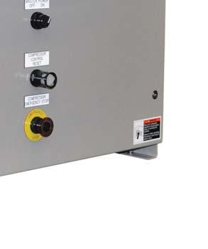
18 Section 1 General Information Hardware Components - PLC Exterior Each Compact Logix PLC may differ, but below are typical components that can found in each PLC. For specific PLC layout, refer to supplied electrical drawings. 1 - HMI Cover 2 - Enclosure Door 3 - Door Latch 4 - Main Enclosure 5 - HMI (Panel View Plus 6) 6 - Master Power 7 - Compressor Control Reset Button 8 - Emergency Stop Button Single Screw Compressor PLC Operation Manual Vilter/Emerson 35391CM


19 Section 1 General Information Hardware Components - Enclosure Door Interior Single Screw Compressor PLC Operation Manual Vilter/Emerson 35391CM 1 7
 16 - Modules 17 - Compact Logix Power Supply 18 - Compact Logix Processor with Ethernet, and Memory Card 19 - Terminal Blocks (DC Low Voltage")
20 Section 1 General Information Hardware Components - Main Enclosure Interior 10 - Terminal Blocks (AC Connections) 11 - Fuses 12 - Relays 13 - DC Power Supplies 14 - Ethernet Switch, 5 Port RJ Panel Heater & Mounting (Not Shown, Field Installed) 16 - Modules 17 - Compact Logix Power Supply 18 - Compact Logix Processor with Ethernet, and Memory Card 19 - Terminal Blocks (DC Low Voltage Connections) 20 - Terminal Blocks (Customer Connections) 21 - Terminal Blocks (Main Power Connections) Single Screw Compressor PLC Operation Manual Vilter/Emerson 35391CM
21 Section 1 General Information Wiring Requirements Incoming power enters on the left bottom wall of the PLC control enclosure. Route these conductors in the space between the sub-panel and inside wall of the enclosure. DC control, analog and communications or network wiring enters on the right bottom wall of the PLC control enclosure. Wiring external to the panel per NEC (NFPA 70), ANSI and UL-598A. Panel construction and wiring per UL-508A for all panels and ANSI and UL-698A for hazardous locations. Electrical transmission, control, and alarm wiring shall be stranded copper no smaller than #14 AWG. Use JIC color code, unless otherwise noted. All control circuits from a source outside of this panel are to be #14 AWG Orange. All control circuit neutrals from a source outside of this panel are to be no smaller than #14 AWG White/ Orange Tracer. All analog inputs are to be connected with shielded cable. Shield terminated at panel side and isolated at device side. All shielding is to be grounded at a single point on the chassis. Analog wiring must be run separate from AC wiring and kept separate within the enclosure. All analog signal wiring shall be grounded at one end only. Ground shield of signal cables. Use alpha P/N 2423C, 3 Cond, 18 AWG, shielded or approved equal. Only one customer network cable to switch. Unused defined as having a previous assignment. Spare defined as no previous assignment. Where applicable, remove jumper between connections if used. All power circuits from a source outside of this panel are to be no smaller than #12 AWG Orange. All power circuit neutrals from a source outside of this panel are to be no smaller than #12 AWG White/ Orange Tracer. All equipment grounds must be Green/Yellow. For ground conductors larger than #6 AWG, apply Green/ Yellow heat shrink or color conductor with marker at both ends. All power sources for heating devices shall be supplied by others. Designated for a trip function (i.e. limit trip, sequence shutdown, etc.). Recommended hard wire connection. Use alpha P/N 2422C, 2 Cond, 18 AWG, shielded or approved equal. Category 6 Ethernet cable is recommended for all of our equipment. SEPARATION OF INTRINSICALLY SAFE CIRCUITS (IF USED) The intrinsically safe wiring enters on the bottom-left wall of the PLC control enclosure. To reduce the possibility of interconnection, additional requirements exist for the separation of intrinsically safe and non-intrinsically safe circuits. Exceptions to this rule may be found in NEC Section (A)(1) and (2). Separation by distance: The distance between intrinsically safe field wiring terminals and non-intrinsically safe field wiring terminals shall be a minimum 8 inches. The distance between intrinsically safe field wiring terminals and non-intrinsically safe field circuits shall be a minimum 5 inches. The distance between intrinsically safe field wiring terminals and non-intrinsically safe field circuits and wiring shall be a minimum 5 inches. The distance between intrinsically safe field wiring terminals and non-intrinsically safe internal wiring shall be a minimum 2 inches. Single Screw Compressor PLC Operation Manual Vilter/Emerson 35391CM 1 9
22 Section 1 General Information VFD Installation Recommendations All wiring to and from the Variable Frequency Drive (VFD) starter shall conform to the National Fire Protetcion Association 70 (NFPA-70), local codes and the manufacturer s guidelines and specifications. Thoroughly read the manufacturer s VFD installation and instruction manuals. In the event of a code and manufacturer recommendation conflict, always use the more stringent standard. Only use an inverter duty rated motor built to NEMA MG1 PART 30 & 31. Always used copper conductors to feed the VFD starter and motor. Use cable with thermoset insulation such as XLPE or XHHW-2 from the VFD to motor. It is preferred to use VFD cable, service wire company or equal, between the VFD and the motor per manufacturer s instructions. It is preferred to use continuous metal conduit to the VFD starter to the motor. If non-metallic conduit is used, VFD cable must be used. If using VFD cable in metal conduit, the metal conduit must be insulated at the motor, so that the metal conduit is not a continuous run. Always use flexible metallic liquid-tight conduit to feed the motor from metallic conduit. Grounding conductor must run from the VFD ground terminals directly to the motor conduit box. Always use proper grounding techniques (Star Method) and sized according to the NFPA 70 NEC. Always use bonding bushings on all conduit ends, Always use bonding bushings on all conduit ends, with proper size braided copper cable bonded to the starter panel. All grounding and bonding conductors and lugs must terminate on bare metal and not to painted surfaces. Always use a minimum of 3% impedance line reactor such as MTE or equal. Where the cables to the motor are longer than 50, always use a load reactor (customer must provide Vilter with cable lengths from feeder to starter and from starter to motor). Where the cables to the motor are longer than 500, always use a DV/DT load filter (customer must provide Vilter with cable lengths from feeder to starter and from starter to motor). Where the cables to the motor are longer than 1000, always use a sine filter (customer must provide Vilter with cable lengths from feeder to starter and from starter to motor). Line and load conductors must be separated, as much as the starter cabinet will allow, and cannot be in the same conduit or cable chase. By no means shall power and control cables run in parallel - cables must be separated, as much as the starter cabinet will allow, and cannot be in the same conduit or cable chase. For analog signals, use twisted shielded control cable rated for 600V. When a generator is feeding a VFD starter, use a 5% line reactor. Some countries require RFI/EMI filters -- please consult country codes and standards. As an insurance policy against motor shaft currents, use a split ring bearing protection ring on the motor shaft with the non-load bearing insulated Single Screw Compressor PLC Operation Manual Vilter/Emerson 35391CM
23 Section 2 Operational Descriptions Overview The following are standard equipment on all compressor units or packages that can be controlled or monitored: Suction Pressure Pressure of the gas measured at the inlet of the compressor. Discharge Pressure Pressure of the gas at the outlet of the compressor. Measured at the oil separator. Oil Filter Inlet Pressure Pressure of oil measured at the inlet of the oil filter(s). Oil Manifold Pressure (Oil Filter Out) Pressure of oil measured after the oil filter(s). Prelube Oil Pressure (at compressor start, Oil Manifold Discharge Pressure) Net Oil Pressure (when compressor running, Oil Manifold Suction Pressure) Suction Temperature Temperature of the gas measured at the inlet of the compressor. Discharge Temperature Temperature of the gas and oil mixture at the outlet of the compressor Separator Oil Temperature Temperature of the oil in the oil separator vessel. Oil Injection Temperature Temperature of the oil as it goes into the compressor. Capacity Slide Valve Position - % Travel of the capacity slide valves. Volume Slide Valve Position - % Travel of the volume slide valves. Main Motor Amperage Current draw by the main motor. Separator Oil Heaters Compressor Main Motor Oil Pump (Full Time or Part Time Selectable) Selectable groups of setpoints for varying operating conditions The following are additional software controls available that are native to all compressor units controlled by the compressor PLC: Monitoring of Instrument Data, Alarms, Trips, and Machine Status by DCS/Central Controller Compressor Capacity control setpoint from DCS/ Central Controller Control of Compressor Loading/Unloading from DCS/Central Controller Capacity control on External Pressure Transducer data from DCS/Central Controller Auto Start/Stop based on process pressure or temperature Control of Local/Remote from DCS/Central Controller Setpoint Group Selectable from DCS/Central Controller Remote Starting and Stopping of the Compressor The following are optional compressor unit-specific items that can be controlled or monitored: Compressor Main Motor VFD Control Main Motor Winding Temperatures Main Motor Bearing Temperatures Motor Vibration (up to 2 sensors) Compressor Vibration (up to 2 sensors) Oil Separator Level Switch Suction Oil Injection Solenoid Valve (Used on Models ) Suction-Discharge Equalizing Solenoid Valve Oil Drain Solenoid Valve Oil Separator Outlet Pressure, to calculate pressure drop across coalescing elements of oil separator 2-Way Oil Mixing Valve Air Cooled Oil Cooler (Step or VFD Type) Oil Cooler Inlet/Outlet Temperatures Oil Cooler Standby Heater The following are optional compressor unit and package items that can be controlled or monitored, specific to refrigeration applications: Air Cooled Condenser (Step Type or VFD Type) Evaporative Air Cooled Condenser Water Cooled Condenser Oil Injection Control Valve Liquid Injection Oil Cooling VPLUS Liquid Oil Cooling Economizer Port Solenoid Valves (single or dual) Hotgas Bypass Solenoid Venturi Oil Recovery Liquid Refrigerant Temperature Temperature of the liquid refrigerant in the chiller. Process Temperature Temperature of the process fluid leaving the chiller 2 1
24 Section 2 Operational Descriptions The following are optional compressor unit and package items that can be controlled or monitored, specific to gas compression applications: Up to 2 Aftercoolers Air Cooled Step Type Air Cooled VFD Type Water Cooled Inlet Scrubber Pressure Drop across vessel Condensate Drain Low/High Level Safety Switches Outlet Scrubber Pressure Drop across vessel Condensate Drain Low/High Level Safety Switches Discharge Recycle Valve Building Enclosure Devices Space Heaters Roof Exhaust Fans Methane %LEL Detector Oil Separator Gas Outlet Temperature Temperature of the gas measured at the discharge of the oil separator. Used to monitor the temperature of the gas relative to dew point. If the compressor is warm and this temperature is too low, the controller will generate an alarm. Oil Separator Gas Outlet Pressure Pressure of the gas measured at the discharge of the oil separator. Used to monitor the pressure drop across the coalescing elements of the oil separator. When pressure drop is too high, the controller will generate an alarm. Reheater Vessel and shell/tube side Temperatures Temperature of the gas measured at the discharge of both the shell and tube sides of the reheater vessel. Periodic Slide Valve Exercising Operational Descriptions and Diagrams STARTING OF THE COMPRESSOR/PERMISSIVES To run the compressor, it must me started from the Start Menu screen on the control panel HMI. Pressing Unit Start in the Start Menu screen will initiate a start if all permissives to initiate a start are met. To initiate a start, the following conditions must be met: Control Power is ON (Emergency Stop button is not pressed, Master Control Relay is energized or activated by remote device, indicated by pilot light on front of panel) No Active Trips When a start is initiated, the compressor will start if all permissives to run the compressor are met. If all permissives to run the compressor are not met, the control will wait in a standby mode until all conditions to run are satisfied. Any condition that the control is waiting on is annunciated on the overview and menu screens and logged in the Event List. To begin the compressor startup sequence, the following conditions must be met: Control Power is ON (Emergency Stop button is not pressed and Master Control Relay is energized, indicated by pilot light on front of panel) No Active Trips Compressor start has been initiated by pressing Unit Start in the Start Menu screen. Remote Permissive input is ON Soft run permissive from the DCS/Central Controller is ON (if control by communications selected) Anti-Recycle Timer is not active Suction Discharge is equalized to within a settable differential Auto Start control is calling for the compressor to start, if Auto Start/Stop is Enabled. If a start is initiated at the compressor, the machine state indicator will indicate Standby and the condition the compressor is waiting on will be annunciated on the overview and menu screens. 2 2
25 Section 2 Operational Descriptions COMPRESSOR STARTUP SEQUENCE IDLE PERMISSIVES MET & UNIT STARTED MOVE CAPACITY & VOLUME SLIDES HOME COMPRESSOR STOP TRIP AUTO CYCLE OFF CAPACITY & VOLUME SLIDE POSITION < 5% TRAVEL STORE (MANIFOLD MINUS DISCHARGE) PRELUBE DIFFERENTIAL PRESSURE ADD 1 TO PRELUBE PUMP START COUNTER. WAIT 5 SECONDS BETWEEN EACH PUMP START TRIP PRELUBE PUMP START COUNTER = 3 PRELUBE NOT SATISFIED AFTER OIL PUMP RUNS FOR 10 SECONDS (SETTABLE) START OIL PUMP START COMPRESSOR PRELUBE PRESSURE (MANIFOLD DIFFERENTIAL PRESSURE) SATISFIED FOR 3 SECONDS PRELUBE PRESSURE NOT SATISFIED FOR 3 SECONDS TRIP PRELUBE PRESSURE SATISFIED FOR 10 SECONDS COMPRESSOR WARM-UP OIL PUMP ON START MODULATING VOLUME SLIDE 50 SECONDS DELAY BEFORE CAPACITY SLIDE VALVES GO TO AUTO AND OIL PUMP SHUTS OFF 7-15 MINUTE DELAY (MODELS ONLY) BEFORE CAPACITY SLIDE VALVES GO TO AUTO AND OIL PUMP SHUTS OFF COMPRESSOR RUNNING MODULATE CAPACITY SLIDE OIL PUMP MAY STOP ON PRESSURE RATIO Figure 2-1. Compressor Startup Sequence Diagram 2 3
26 Section 2 Operational Descriptions AUTO START-STOP When enabled, the Auto Start-Stop feature will allow the compressor to cycle on and off based on the controlled pressure or temperature. The Anti-Recycle timer still applies when Auto Start-Stop is enabled. Additional variables that factor in to Auto Start-Stop are described below: Auto Start Pressure/Temperature: Pressure or Temperature at which the control will start the compressor. Auto Start Delay: Amount of time that the Auto Start Pressure/Temperature must be met before the compressor is commanded to start. Auto Stop Pressure/Temperature: Pressure or Temperature at which the control will stop the compressor. Auto Stop Delay: Amount of time that the Auto Stop Pressure/Temperature must be met with the capacity slide at or below Minimum Slide Position before the compressor is commanded to stop. Minimum Slide Position: Position the capacity slide must be at or below before the compressor is commanded to stop. When Auto Start-Stop control is enabled, it will function as follows: When Auto Start Pressure/Temperature is met for the Auto Start Delay Time, the compressor will be commanded to start. When the Auto Stop Pressure/Temperature is met and the capacity slide has decreased to the Minimum Slide Position for the Auto Stop Delay time, the compressor will be commanded to stop. ANTI-RECYCLE After the compressor main motor stops, it is not allowed to re-start again for a settable time. This is to protect the compressor from damage by allowing oil to drain from it before the next start. If the Anti-Recycle timer is active, a banner will appear on the overview and menu screens that shows the remaining time. If a start is initiated, the compressor state indicator will indicate Standby until the Anti-Recycle timer is done. If all other permissives are met, the compressor will re-start. 2 4 CAPACITY SLIDE CONTROL Reference examples, Figures 2-2, 2-3 and 2-4 While the compressor is running, the controller will automatically adjust the position of the compressor capacity slide valve to hold the desired pressure or temperature. Three control methods are available: Discharge Pressure Control: Compressor loads to increase discharge Pressure to desired setpoint Suction Pressure Control: Compressor loads to lower suction pressure to desired setpoint Process Temperature Control: Compressor Loads to lower process temp to desired setpoint. An instrument to monitor the Process Temperature is required. The capacity slide control of the PLC operates by periodically calculating an adjustment to the capacity slide position based on where the selected process variable is in relation to the target setpoint. When the process pressure or temperature is far away from the setpoint, capacity slide position is adjusted by the defined maximum. As the control pressure or temperature gets closer to setpoint, smaller adjustments are made to the capacity slide position. All of the variables that factor in to this calculation are described below: Target pressure or Temperature the desired suction pressure, discharge pressure, or process temperature that the machine will try to maintain. Upper Proportional Deadband Range above Target pressure or Temperature where no capacity slide adjustment will be made. Lower Proportional Deadband Range below Target pressure or Temperature where no capacity slide adjustment will be made. Upper Proportional Band Range above Target pressure or Temperature where adjustments to capacity slide position are made proportional to the difference between Target pressure or Temperature and Actual. Outside this range, the adjustment made will be the set maximum. Lower Proportional Band - Range below Target pressure or Temperature where adjustments to capacity slide position are made proportional to the difference between Target pressure or Temperature and Actual. Outside this range, the adjustment made will be the set maximum. Load Interval Time Cycle time for calculating capacity slide position adjustment when the controller is calling for the machine to increase capacity slide position. Where the Load Interval Time is T1, the control will make an adjustment calculation every T1 seconds.
27 Section 2 Operational Descriptions Unload Interval Time Cycle time for calculating capacity slide position adjustment when the controller is calling for the machine to decrease capacity slide position. Where the Load Interval Time is T2, the control will make an adjustment calculation every T2 seconds. Max Load Adjustment per Interval Maximum position adjustment that can be made when the control is calling for the machine to increase capacity slide position. Where the Maximum Load Adjustment is A1, the capacity slide position will increase by A1% every cycle of the Load Interval Timer when outside the bandwidth range. When inside the bandwidth range, the capacity slide position adjustment will be a percentage of A1. Max Unload Adjustment per Interval Maximum position adjustment that can be made when the control is calling for the machine to decrease capacity slide position. Where the Maximum Unload Adjustment is A2, the capacity slide position will increase by A2% every cycle of the Unload Interval Timer when outside the bandwidth range. When inside the bandwidth range, the capacity slide position adjustment will be a percentage of A2. When the compressor is stopped, the capacity slide will return to its minimum position. SUCTION PRESSURE & PROCESS TEMPERATURE PRESSURE OR TEMPERATURE *EVERY CYCLE OF INTERVAL TEMPERATURE, MAX LOAD ADJUSTMENT IS MADE (CAP INCREASE) UPPER PROPORTIONAL BAND (10 PSID) UPPER PROPORTIONAL DEADBAND LOWER PROPORTIONAL DEADBAND LOWER PROPORTIONAL BAND (5 PSID) *EVERY CYCLE OF INTERVAL TIMER, MAX UNLOAD ADJUSTMENT IS MADE (CAPACITY DECREASE) 60 PSIG *EVERY CYCLE OF INTERVAL TIMER, CAPACITY COMMAND WILL INCREASE BY CALCULATED AMOUNT, PROPORTIONAL TO ERROR 1 PSID (NO ADJUSTMENT) 1 PSID (NO ADJUSTMENT) 51 PSIG TARGET (50 PSIG) 49 PSIG *EVERY CYCLE OF INTERVAL TIMER, CAPACITY COMMAND WILL DECREASE BY CALCULATED AMOUNT, PROPORTIONAL TO ERROR 45 PSIG DISCHARGE PRESSURE PRESSURE *EVERY CYCLE, UNLOAD BY MAX UNLOAD ADJUSTMENT UPPER BANDWIDTH 5 PSID UPPER PROPORTIONAL DEADBAND LOWER PROPORTIONAL DEADBAND LOWER BANDWIDTH 10 PSID *EVERY CYCLE, LOAD BY MAX LOAD ADJUSTMENT 105 PSIG *EVERY CYCLE OF INTERVAL TIMER, MAKE PROPORTIONAL ADJUSTMENT (CAPACITY DECREASE) 2 PSID (NO ADJUSTMENT) 2 PSID (NO ADJUSTMENT) *EVERY CYCLE OF INTERVAL TIMER, MAKE PROPORTIONAL ADJUSTMENT (CAPACITY INCREASE) 102 PSIG TARGET (100 PSIG) 98 PSIG 90 PSIG Figure 2-2. Capacity Slide Control Diagram (Example) 2 5
28 Section 2 Operational Descriptions +UPPER PROPORTIONAL BAND +UPPER PROPORTIONAL DEADBAND ACTUAL PRESSURE TARGET -LOWER PROPORTIONAL DEADBAND -LOWER PROPORTIONAL BAND COMMANDED CAPACITY SLIDE VALVE POSITION MAX LOAD PER INTERVAL (%) MAX LOAD PER INTERVAL (%) LOAD INTERVAL CYCLE TIME (SECONDS) UNLOAD INTERVAL CYCLE TIME (SECONDS) Figure 2-3. Operational Diagram - Capacity Slide, Discharge Pressure (Example) 2 6
29 Section 2 Operational Descriptions SUCTION PRESSURE TARGET DISCHARGE PRESSURE 100 CAPCITY SLIDE SPEED / CAPACITY 50 MOTOR SPEED 0 START 10 SECOND DELAY (FIXED) 10 SECOND DELAY (FIXED) Figure 2-4. Operational Diagram - Capacity Slide, Suction Pressure per Process Temperature (Example) 2 7
30 Section 2 Operational Descriptions OPERATING MODES The loading and unloading of the compressor can be configured to operate in several ways, depending on the needs of the site. This mode selection is made at the Start Menu screen. There are four basic modes, described below: Local-Auto: The compressor will adjust the position of the capacity slide automatically using the control s capacity control algorithm. The target pressure or temperature setpoint is set on the compressor s local HMI. Local-Manual: The operator is in control of the capacity slide from the local HMI. When in Local-Manual mode, the operator controls the capacity slide position using increase/decrease pushbuttons on the compressor overview screen. Remote-Auto: The compressor will adjust the position of the capacity slide automatically using the control s capacity control algorithm. The target pressure or temperature setpoint is defined by the DCS/Central Controller via communications. (NOTE: Control by Communications must be enabled to use this mode.) Remote-Manual: The capacity slide position is controlled by a DCS or Central Controller. There are four selectable methods of using Remote-Manual Control, settable from the HMI s configuration screen. Caphold-Ethernet: Capacity slide valve position commands are given by the central controller/ DCS via communications. (NOTE: Control by Communications must be enabled to use this method.) Caphold-4-20mA Hardwired: Capacity slide valve position commands are given by the central controller/dcs via a 4-20mA analog signal. The scaling is 4mA = 0% Capacity Slide Position, 20mA = 100% capacity slide position. Control by Communications does not need to be enabled to use this method. Discrete Load/Unload Ethernet: Capacity slide valve increase and decrease commands are given by the central controller/dcs via communications. (NOTE: Control by Communications must be enabled to use this method.) Discrete Load/Unload Hardwired: Capacity slide valve increase and decrease commands are given by the central controller/dcs via discrete hardwired inputs. Control by communications does not need to be enabled to use this method. In any of the above modes, all local safeties and load limits still apply and will override external commands. For safety reasons, remote mode is only enabled under certain conditions. If these conditions are not met, the machine will revert to local mode. To be able to enter remote mode, the one of the following must be true: Auto Mode Selected, Control By Communications Enabled. Manual Mode Selected, Remote Manual Control Source is Hardwired Manual Mode Selected, Control by Communications Enabled In the event that the communications link between the compressor PLC and the central controller/dcs is lost, the action taken is selectable from the Configuration screen. The machine will Trip or revert to Local mode and continue to run depending on the selection. The compressor PLC can be remotely commanded to Local or Remote Mode if Control by Communications is enabled. NOTE If a main motor VFD is being used for capacity control, only discrete commands may be used in Remote- Manual Control. LOAD LIMITS AND FORCED UNLOADING Reference example, Figure 2-5 To protect the compressor and process, the controller will inhibit the compressor from loading or force it to unload if certain variables get outside of set ranges. Three load limiting variables are continuously monitored: Low Suction Pressure High Discharge Pressure High Main Motor Amps There are independent Load Limit Setpoints specific to Setpoint 1 and Setpoint 2 setpoint groups, allowing load limits to be specific to unique operating conditions. For each of the three variables, three setpoints are active: Inhibit Loading: when this setpoint is reached, the compressor will not be allowed to continue loading. Unload at: when this setpoint is reached, the capacity slide will move in the decrease direction continuously (forced unload) until the Unload To setpoint is reached. Unload To: this is the setpoint at which the capacity slide will stop unloading from a forced unload condition. 2 8
31 Section 2 Operational Descriptions When a load limit or forced unload condition is active it will be annunciated in the status banner on the overview and menu HMI screens, and will also be logged in the event list. LOW SUCTION PRESSURE INHIBIT LOAD A D FORCE UNLOAD TO C FORCE UNLOAD AT SUCTION PRESSURE B (A) CAPACITY SLIDE WILL NOT INCREASE (B & C) CAPACITY SLIDE WILL DECREASE UNTIL PRESSURE REACHES C (D) CAPACITY SLIDE MAY INCREASE HIGH DISCHARGE PRESSURE OR AMPS FORCE UNLOAD AT B FORCE UNLOAD TO C INHIBIT LOAD A D DISCHARGE PRESSURE OR AMPS (A) CAPACITY SLIDE WILL NOT INCREASE (B & C) FORCED UNLOAD UNTIL DISCHARGE PRESSURE/AMPS REACHES C (D) CAPACITY SLIDE ALLOWED TO INCREASE Figure 2-5. Operational Diagram - Load Limits / Forced Unloading (Example) 2 9
32 Section 2 Operational Descriptions VFD CAPCITY CONTROL When a VFD is used on the compressor main motor to control capacity, it works in conjunction with the capacity slide valve to maintain the Target pressure or Temperature. At start, the compressor main motor will run at 50% speed until the capacity slide reaches its maximum position. At this point, the VFD will begin adjusting the speed of the main motor to maintain the target pressure or temperature. The speed adjustments made by the controller follow the same algorithm as the capacity slide. Additional variables that factor into the operation of a main motor VFD are described below: Max Speed Increase per Interval Maximum motor speed adjustment that can be made when the control is calling for the machine to increase motor speed. Where the Maximum Speed Increase is S 1, the main motor will speed up by S 1 % every cycle of the Load Interval Timer when outside the bandwidth range. When inside the bandwidth range, the motor speed adjustment will be a percentage of S 1. Max Speed Decrease per Interval Maximum motor speed adjustment that can be made when the control is calling for the machine to decrease motor speed. Where the Maximum Speed Decrease is S 2, the main motor will slow down by S 2 % every cycle of the Unload Interval Timer when outside the bandwidth range. When inside the bandwidth range, motor speed adjustment will be a percentage of S 2. When the compressor is stopped, the volume slide valve is commanded to go to its minimum position. SAFETIES The compressor controller continuously monitors operational and process data and annunciates an alarm and/ or stops the machine if any condition becomes abnormal. Two levels of safeties exist when an abnormal condition is detected. Alarm: If active, alarms are annunciated on the compressor HMI. When activated, a popup screen showing the date and time of the alarm and alarm message will appear. Alarms are also logged in the Event List. An alarm serves only as a warning to the operator; if an alarm is active the machine is still allowed to run. Trip: If active, trips will shut the machine down or not allow the compressor to start. Trips are annunciated on the compressor HMI. When activated, a popup screen showing the date and time of the trip and trip message will appear. Trips are also logged in the Event List. The Alarm Reset pushbutton on the overview screen will reset any active alarms or trips if the abnormal condition has been removed. For a comprehensive list of alarms and trips and possible causes, see the troubleshooting guide in this manual. VOLUME SLIDE CONTROL When the compressor is running, the volume slide valve adjusts automatically to operating conditions for optimal efficiency. The volume slide position is determined by a lookup table that takes into account the size and model of compressor, type of refrigerant or gas being compressed, capacity slide position, and pressure ratio. An offset can be applied to the volume slide s calculated target position to adjust it for unique running conditions. In Compressor Control Setpoints page 2, the setpoints below are available: Volume Slide Adjustment Factor: amount of offset that will be applied to the calculated volume slide position target. Capacity Slide Range Adjustment Factor is Applied: The volume slide adjustment factor or offset will be applied when the capacity slide is within this range. The volume slide may be manually controlled, although it is best to leave it in Auto Mode. Manual volume slide control may be used when calculating an offset to apply to the volume slide calculation. The volume slide mode is settable in the Volume Slide Details screen EMERGENCY STOP Reference Figure 2-6 The Emergency Stop circuit in the compressor control panel energizes the Master Control Relay, which provides power to PLC outputs that control actuators, heaters, motor starters, valves, etc. The Master Control Relay may be energized by pressing the Control Power On illuminated pushbutton on the door of the compressor control panel. When the Master Control Relay is energized, the Control Power On pushbutton will illuminate. The following conditions must be satisfied to energize the Master Control Relay: Emergency Stop pushbutton on the door of the compressor control panel must be pulled out. Any additional Emergency stops or safety devices tied in to the Emergency Stop circuit must be reset. The compressor PLC must be booted up and operational. The 24-volt DC power supplies in the compressor control panel must be powered up and OK.
33 Section 2 Operational Descriptions Figure 2-6. Control Panel Master Power and Emergency Stop Electrical Circuit OIL HEATERS Immersion Heaters in the oil separator are controlled by the compressor PLC to maintain warm oil. The heaters cycle on and off to maintain a desired separator oil temperature range. OIL DRAIN SOLENOID If installed, the oil drain solenoid valve opens for a settable time on compressor stop to allow oil to drain from the compressor. It also opens during the prelube retry wait periods in the prelube sequence. SUCTION OIL INJECTION SOLENOID Used on 401mm screw machines (models ). If installed, the suction oil injection solenoid feeds additional oil from the oil separator to compressor suction on start. The valve is opened for a settable time after the compressor main motor starts. SUCTION-DISCHARGE EQUALIZING SOLENOID If installed, the equalizing solenoid opens for a settable time on compressor stop to equalize pressure between suction and discharge of the compressor. 2 11
34 Section 2 Operational Descriptions PID CONTROLS (1 OF 2) VALVE POSITION (100% OPEN) HOT OIL FROM OIL SEPARATOR OIL MIXING VALVE M OIL COOLER COOL OIL FROM OIL COOLER OIL FLOW TARGET OIL INJECTION TEMPERATURE MACHINE STARTS VALVE POSITION (% OPEN) Figure 2-7. Operational Diagram - 2-Way Oil Mixing Valve 2-WAY OIL MIXING VALVE Reference Figure 2-7 If installed, the 2-way oil mixing valve modulates to control compressor Oil Injection Temperature. The valve is installed in the compressor oil circuit such that when it closes, it forces more oil through the cooler. The valve position is adjusted to mix the correct amount of hot oil from the oil separator and cool oil coming back from the oil cooler. A PID controller determines the valve position command to maintain Oil Injection Temperature. On rising temperature the controller will command the valve to close; on falling temperature the controller will command the valve to open. When the compressor is stopped, the 2-way mixing valve is commanded to 100% open. When running, the valve will remain open until Oil Injection Temperature begins to rise, and then begin to close. OIL INJECTION VALVE If installed, the oil injection valve is a motorized valve that regulates the amount of oil going into the compressor. The valve position is determined by a lookup table. The percentage compressor loading determines the position of the valve. When the compressor is stopped, the valve will be commanded to 100% open. When the compressor is running, the valve will begin to modulate when oil injection temperature reaches a Start setpoint, adjustable on the Compressor Control Setpoints screens. When the compressor is running, and oil injection temperature is above the Start setpoint, the valve will go to the commanded position calculated by the controller. NOTE The oil injection valve must be configured to be reverse acting. 4mA = 100% open, 20 ma = 0% open. 2 12
35 Section 2 Operational Descriptions TE OIL COOLER TARGET OUTPUT TEMPERATURE TEMPERATURE (OIL COOLER OUTLET TEMPERATURE) START TEMPERATURE FAN SPEED MINIMUM FAN SPEED Figure 2-8. Operational Diagram - Air Cooled Oil Cooler (VFD Type) AIR COOLED OIL COOLER (VFD TYPE) Reference Figure 2-8 If installed, the VFD type air cooled oil cooler is a heat exchanger that uses one or more fans running on a VFD to control the oil temperature at its outlet. A PID controller adjusts the speed of the fan(s) to control the temperature at the outlet of the oil cooler. When the temperature of the oil at the outlet of the cooler exceeds the desired temperature plus a deadband, the fan(s) will increase speed to add more cooling. When outlet temperature drops below the desired temperature minus a deadband, the fan(s) will decrease speed. When the compressor is stopped, the oil cooler fan(s) will stop. When the compressor is running and the oil cooler outlet temperature rises above the Oil Cooler Start temperature set in the VFD Type Oil Cooler Setpoints screen, the fan(s) will start at a settable minimum speed. When the compressor is running and the oil cooler outlet temperature is above the deadband, the PID controller will increase fan speed. When the compressor is running and the oil cooler outlet temperature is below the deadband, the PID controller will decrease fan speed. OIL COOLER TEMPERATURES It is possible to monitor Oil Cooler Inlet Temperature, and monitor Oil Cooler Outlet Temperature if an oil cooler is not being controlled. OIL COOLER STANDBY HEATER If installed, a heater within the remote oil cooler is controlled by the compressor PLC to maintain warm oil. The heater cycles on and off to maintain a desired oil cooler outlet temperature range. Setpoints to control the Oil Cooler Standby Heater are on the Oil Cooler Control Setpoints (Step or VFD Type) Screen. 2 13
36 Section 2 Operational Descriptions TE AFTERCOOLER TARGET OUTPUT TEMPERATURE AFTERCOOLER OUTLET TEMPERATURE START TEMPERATURE FAN SPEED MINIMUM FAN SPEED Figure 2-9. Operational Diagram - Air Cooled Aftercooler (VFD Type) AIR COOLED AFTERCOOLER (VFD TYPE) Reference Figure 2-9 If installed, the VFD type air cooled aftercooler is a heat exchanger that uses one or more fans running on a VFD to remove heat from the gas discharged from the compressor. The VFD speeds up or slows down the fan motor to control the amount of cooling done by the aftercooler. A PID controller adjusts the speed of the fan(s) to maintain the outlet gas temperature of the aftercooler. When the aftercooler outlet temperature exceeds the desired temperature plus a deadband, the fan(s) will increase speed to add more cooling. When aftercooler outlet temperature drops below the desired temperature minus a deadband, the fan(s) will decrease speed. When the compressor is stopped, the aftercooler fan(s) will stop. When the compressor is running and the gas aftercooler outlet temperature rises above the Start Aftercooler At set in the VFD Type Aftercooler Setpoints screen, the fan(s) will start at a settable minimum speed. When the compressor is running and the aftercooler outlet temperature is above the deadband, the PID controller will increase fan speed. When the compressor is running and the aftercooler outlet temperature is below the deadband, the PID controller will decrease fan speed. 2 14
37 Section 2 Operational Descriptions PT CONDENSER TARGET OUTPUT PRESSURE CONDENSING PRESSURE START PRESSURE FAN SPEED MINIMUM FAN SPEED Figure Operational Diagram - Air Cooled Condenser (VFD Type) AIR COOLED CONDENSER (VFD TYPE) Reference Figure 2-10 If installed, the VFD type air cooled condenser is a heat exchanger that uses one or more fans running on a VFD to condense refrigerant vapor into a liquid. The VFD speeds up or slows down the fan motor to control the amount of cooling done by the condenser. A PID controller adjusts the speed of the fan(s) to control condensing pressure. When the condensing pressure exceeds the desired pressure plus a deadband, the fan(s) will increase speed to add more cooling. When condensing pressure drops below the desired temperature minus a deadband, the fan(s) will decrease speed. When the compressor is stopped, the condenser fan(s) will stop. When the compressor is running and the oil cooler outlet temperature rises above the Condenser Start Pressure set in the VFD Type Condenser Setpoints screen, the fan(s) will start at a settable minimum speed. When the compressor is running and the condensing pressure is above the deadband, the PID controller will increase fan speed. When the compressor is running and the condensing pressure is below the deadband, the PID controller will decrease fan speed. EVAPORATIVE CONDENSER If installed, an evaporative condenser incorporates a water circulating pump that mists water over the condenser to provide additional cooling. When using with step-type condensers, the pump can be added or removed from the step sequence as if it were another fan. The pump will start when the steps that it is enabled are active. When using with VFD-type condensers, the pump can be enabled or disabled by a selection on the condenser control setpoints screen. When enabled, the pump starts at the same time as the fan. 2 15
38 Section 2 Operational Descriptions TE OIL COOLER TARGET START TEMPERATURE OR PRESSURE STEP # FANS TURNING ON FANS TURNING OFF TEMPERATURE OR PRESSURE 1 STEP ADDED EVERY CYCLE OF CYCLE TIMER TARGET DEADBAND DEADBAND NO STEPS ADDED OR REMOVED STEP # 1 STEP REMOVED EVERY CYCLE OF CYCLE TIMER Figure Operational Diagram - All Air Cooled Oil Coolers (Step Type) AIR COOLED OIL COOLER (STEP TYPE) Reference Figure 2-11 If installed, the step type air cooled oil cooler is a heat exchanger that uses multiple fans to control the oil temperature at its outlet. The controller starts and stops fans in a sequence to control the temperature at the outlet of the oil cooler. When the temperature of the oil at the outlet of the cooler exceeds the desired temperature plus a deadband, fans will be turned on after a time delay to add more cooling. When outlet temperature drops below the desired temperature minus a deadband, fans will be turned off after a time delay. When the compressor is stopped, all oil cooler fans are turned off. When the compressor is running and the oil cooler 2 16
39 Section 2 Operational Descriptions outlet temperature rises above the Oil Cooler Start temperature set in the Step Type Oil Cooler Setpoints screen, the first fan (or group of fans) will start. When the compressor is running and the oil cooler outlet temperature is above the deadband, a fan (or group of fans) will start each time through the Step Dwell Time. When the compressor is running and the oil cooler outlet temperature is below the deadband, a fan (or group of fans) will stop each time through the Step Dwell Time. Once started, the first fan or group of fans will remain running until the compressor stops. AIR COOLED AFTERCOOLER (STEP TYPE) Reference Figure 2-11 If installed, the step type air cooled aftercooler is a heat exchanger that uses multiple fans to remove heat from the gas discharged from the compressor. The number of fans that run is determined by the gas temperature at the outlet of the aftercooler. The controller starts and stops fans in a sequence to control the gas temperature at the outlet of the aftercooler. When the aftercooler outlet temperature exceeds the desired temperature plus a deadband, fans will be turned on after a time delay to add more cooling. When aftercooler outlet temperature drops below the desired temperature minus a deadband, fans will be turned off after a time delay. When the compressor is stopped, all aftercooler fans are turned off. When the compressor is running and the aftercooler outlet temperature rises above the Start Aftercooler At temperature set in the Step Type Aftercooler Setpoints screen, the first fan (or group of fans) will start. When the compressor is running and the aftercooler outlet temperature is above the deadband, a fan (or group of fans) will start each time through the Step Dwell Time. When the compressor is running and the aftercooler outlet temperature is below the deadband, a fan (or group of fans) will stop each time through the Step Dwell Time. Once started, the first fan or group of fans will remain running until the compressor stops. AIR COOLED CONDENSER (STEP TYPE) Reference Figure 2-12 and 2-11 for curves If installed, the step type air cooled condenser is a heat exchanger that uses multiple fans to condense refrigerant vapor to a liquid. The number of fans that run is determined by the refrigerant pressure at the condenser. The controller starts and stops fans in a sequence to control the condensing pressure. When the condensing pressure exceeds the desired pressure plus a deadband, fans will be turned on after a time delay to add more cooling. When condensing pressure drops below the desired pressure minus a deadband, fans will be turned off after a time delay. When the compressor is stopped, all condenser fans are turned off. When the compressor is running and the oil cooler outlet temperature rises above the Condenser Start pressure set in the Step Type Condenser Setpoints screen, the first fan (or group of fans) will start. When the compressor is running and the condensing pressure is above the deadband, a fan (or group of fans) will start each time through the Step Dwell Time. When the compressor is running and the condensing pressure is below the deadband, a fan (or group of fans) will stop each time through the Step Dwell Time. Once started, the first fan or group of fans will remain running until the compressor stops. PT CONDENSER Figure Operational Diagram - Air Cooled Condenser 2 17
40 Section 2 Operational Descriptions GAS IN WATER COOLED GAS AFTERCOOLER TE COOLED GAS OUT COOL WATER WARM WATER TARGET OUTPUT TEMPERATURE GAS OUTLET TEMPERATURE START TEMPERATURE FAN SPEED MINIMUM FAN SPEED Figure Operational Diagram - Water Cooled Gas Aftercooler WATER COOLED GAS AFTERCOOLER Reference Figure 2-13 If installed, the water-cooled gas aftercooler is a heat exchanger that uses a modulating valve to control cooling water flow to remove heat from the gas discharged by the compressor. The valve position is adjusted to control the amount of cooling done by the aftercooler. A PID controller adjusts the opening degree of the modulating valve to maintain a desired temperature at the outlet of the gas aftercooler. When the aftercooler outlet temperature exceeds the desired pressure plus a deadband, the valve will open further to add more cooling. When aftercooler outlet temperature drops below the desired temperature minus a deadband, the valve will begin to close. When the compressor is stopped, the valve will be commanded to 0% open (full close). When the compressor is running and the condensing pressure rises above the Open Valve At setpoint in the Water Cooled Aftercooler Setpoints screen, the valve will open to a settable minimum position. When the compressor is running and the aftercooler outlet temperature is above the deadband, the PID controller will increase the valve opening degree. When the compressor is running and the aftercooler outlet temperature is below the deadband, the PID controller will decrease the valve opening degree. 2 18
41 Section 2 Operational Descriptions WATER COOLED CONDENSER PT DISCHARGE LIQUID COOL WATER WARM WATER TARGET OUTPUT PRESSURE CONDENSING PRESSURE START PRESSURE FAN SPEED MINIMUM FAN SPEED Figure Operational Diagram - Water Cooled Condenser WATER COOLED CONDENSER Reference Figure 2-14 If installed, the water-cooled condenser is a heat exchanger that uses a modulating valve to control cooling water flow to condense refrigerant vapor into a liquid. The valve position is adjusted to control the amount of cooling done by the condenser. A PID controller adjusts the opening degree of the modulating valve to control condensing pressure. When the condensing pressure exceeds the desired pressure plus a deadband, the valve will open further to add more cooling. When condensing pressure drops below the desired temperature minus a deadband, the valve will begin to close. When the compressor is stopped, the valve will be commanded to 0% open (full close). When the compressor is running and the condensing pressure rises above the Condenser Start Pressure set in the Water Cooled Condenser Setpoints screen, the valve will open to a settable minimum position. When the compressor is running and the condensing pressure is above the deadband, the PID controller will increase the valve opening degree. When the compressor is running and the condensing pressure is below the deadband, the PID controller will decrease valve opening degree. 2 19
42 Section 2 Operational Descriptions LIQUID REFRIGERANT LIQUID INJECTION VALVES M S SUCTION COMPRESSOR TE DISCHARGE TARGET OUTPUT PRESSURE DISCHARGE TEMPERATURE START PRESSURE VALVE POSITION MINIMUM VALVE POSITION Figure Operational Diagram - Liquid Injection Valve LIQUID INJECTION VALVE Reference Figure 2-15 If installed, liquid injection is a method of oil cooling where liquid refrigerant is injected into a port on the compressor. A modulating valve regulates the amount of liquid allowed into the compressor to control the amount of cooling done by liquid injection. A PID controller adjusts the opening degree of the modulating valve to control compressor discharge temperature (temperature of the gas and oil mixture leaving the compressor). When the discharge temperature exceeds the desired temperature plus a deadband, the valve will open further to add more cooling. When discharge temperature drops below the desired temperature minus a deadband, the valve will begin to close. When the compressor is stopped, the valve will be commanded to 0% open (full closed). When the compressor is running, the discharge temperature rises above the Open Valve Above setpoint and Separator Oil Temperature rises above Oil Separator Override Temp in the Liquid Injection Valve Setpoints screen, the valve will open to a settable minimum position. When the compressor is running and the discharge temperature is above the deadband, the PID controller will increase the valve opening degree. When the compressor is running and the discharge temperature is below the deadband, the PID controller will decrease valve opening degree. 2 20
43 Section 2 Operational Descriptions VPLUS S LIQUID REFRIGERANT SUCTION COMPRESSOR TE DISCHARGE TARGET OUTPUT TEMPERATURE DISCHARGE TEMPERATURE START TEMPERATURE PUMP SPEED MINIMUM PUMP SPEED Figure Operational Diagram - VPLUS VPLUS LIQUID INJECTION PUMP Reference Figure 2-16 If installed, VPLUS liquid injection is a method of oil cooling where liquid refrigerant is pumped through a nozzle in the discharge housing of the compressor. A variable speed pump regulates the amount of liquid pumped into the compressor to control the amount of cooling. A PID controller adjusts the speed of the VPLUS pump to control compressor discharge temperature (temperature of the gas and oil mixture leaving the compressor). When the discharge temperature exceeds the desired temperature plus a deadband, the pump will increase speed to add more cooling. When discharge temperature drops below the desired temperature minus a deadband, the pump will decrease speed. When the compressor is stopped, the pump is stopped. When the compressor is running, the discharge temperature rises above the Start Pump At setpoint and Separator Oil Temperature rises above Oil Separator Override Temp in the VPLUS Pump Setpoints screen, the pump will start at a settable minimum speed. When the compressor is running and the discharge temperature is above the deadband, the PID controller will increase the pump speed. When the compressor is running and the discharge temperature is below the deadband, the PID controller will decrease the pump speed. 2 21
44 Section 2 Operational Descriptions DISCHARGE PRESSURE DISCHARGE RECYCLE SETTING COMPRESSOR CONTROL TARGET 100 DISCHARGE RECYCLE VALVE POSITION (% OPEN) 0 Figure Operational Diagram - Discharge Recycle Valve DISCHARGE RECYCLE VALVE Reference Figure 2-17 NOTE Discharge recycle valve must be controlled by others when multiple compressors are connected to a common header. If installed, the discharge recycle valve is a motorized or air actuated valve that recycles discharge gas back to the suction of the compressor. The valve acts as a regulator, opening to maintain the set pressure in the discharge line. A PID controller adjusts the opening degree of the valve to maintain a desired pressure on the high pressure side of the valve. When the recycle control pressure exceeds the desired pressure plus a deadband, the valve will start to open to recycle high pressure gas back to suction. 2 22
45 Section 2 Operational Descriptions ECONOMIZER SOLENOID(S) If installed, an economizer is a heat exchanger that operates at an intermediate pressure, above suction pressure but below discharge pressure. Up to two solenoids control when the economizer becomes part of the refrigeration process. The compressor controller opens and closes the economizer port solenoid valves based on ON and OFF capacity slide position setpoints. The economizer solenoid is typically energized when capacity slide valve position is above a settable value. When the compressor is stopped, economizer solenoid valves are closed. When the compressor is running, the economizer port solenoid will open when capacity slide position is greater than the ON Above Setpoint in the Compressor Control Setpoints Screens. When the compressor is running, the economizer port solenoid will close when capacity slide position is less than the OFF Below Setpoint in the Compressor Control Setpoints Screens. HOTGAS BYPASS SOLENOID If installed, the hotgas bypass solenoid valve enables a regulator that circulates discharge hotgas back to suction to simulate a load on the compressor by raising the suction pressure. It is typically enabled on low load conditions to prevent the compressor from shutting down on low suction pressure. The compressor controller opens and closes the hotgas bypass solenoid valve based on ON and OFF capacity slide position setpoints. The hotgas bypass solenoid is typically energized when capacity slide position is below a settable value. When the compressor is stopped, the hotgas bypass solenoid is closed. When the compressor is running, the hotgas bypass solenoid will open when capacity slide position is less than the ON Below Setpoint in the Compressor Control Setpoints Screens. When the compressor is running, the economizer port solenoid will close when capacity slide position is less than the OFF Below Setpoint in the Compressor Control Setpoints Screens. VENTURI OIL RECOVERY If installed, the venturi oil recovery system uses a group of solenoid valves that function together to return any oil that has accumulated in the chiller back to the compressor. When the solenoid valves are energized, discharge hotgas passes through a venturi to draw out any oil that may have accumulated in the chiller. Venturi Oil Recovery is typically used in Freon or Propane applications where the oil is less dense than the liquid refrigerant and tends to float on top. Oil recovery is activated by a level switch that senses low oil level in the oil separator. When activated, the venturi oil recovery solenoids will cycle on and off by a settable cycle timer. ON time and OFF time are settable in the Compressor Control Setpoints screens. GAS SCRUBBERS A gas scrubber (or knockout drum) is a vessel with a demister pad or coalescing elements installed to remove moisture and other contaminants from the gas stream. Gas scrubbers may be installed on the suction side or discharge side of a gas compressor (if an aftercooler is used, the scrubber is installed downstream of the aftercooler), or on the inlet or outlet side of a gas chiller. A condensate pump or solenoid valve drains accumulated moisture from the vessel. Gas scrubbers include the following devices: Pressure transducers on the inlet and outlet of the vessel used to measure pressure drop across the demister pad or coalescing elements to help determine when to clean or replace. Level switches to monitor the condensate level: LSH (High Level) when liquid level reaches the LSH level switch, an alarm is annunciated on the compressor HMI. LSHH (High High Level) when liquid level reaches the LSHH level switch, an alarm or trip is annunciated on the compressor HMI. The alarm or trip action is configurable depending on the site and location of the vessel. If trip action is selected, the compressor will shut down if the LSHH is activated. Typically the purpose of the LSHH is to alarm or shut down the compressor to prevent bringing liquid into the compressor suction. LSLL (Low Low Level) when liquid level drops below the LSLL level switch, an alarm or trip is annunciated on the compressor HMI. The alarm or trip action is configurable depending on the site and location of the vessel. If trip action is selected, the compressor will shut down if the LSLL is activated. Typically the purpose of the LSLL is to detect if the liquid seal is lost to prevent introducing gas into the condensate drain system. Condensate Drain System: A drain pump or solenoid valve will turn on when the liquid level in the scrubber reaches the Cutin 2 23
46 Section 2 Operational Descriptions level switch. The drain pump or solenoid valve will turn off when the liquid level in the scrubber drops to the Cutout level switch. Dual pumps may be used. Selection of Pump A or B is made in the Configuration screen. BUILDING ENCLOSURE DEVICES If the compressor unit is mounted inside a building enclosure, the following are monitored/controlled: Space Heater maintains a desired temperature range inside the enclosure. Space Heater ON and OFF setpoints are in the compressor control setpoint screens. Exhaust Fans maintains a desired temperature range inside the enclosure. Exhaust Fan ON and OFF setpoints are in the compressor control setpoint screens. If the methane detector %LEL reaches alarm level, the exhaust fans will also turn on until the alarm is cleared. Methane Detector monitors the %LEL of the air inside the enclosure. Generates an alarm and trip. Alarm and trip setpoints are settable in the Alarm and Trip Setpoints screen. Smoke Detector If triggered by smoke within the enclosure, will shut down the compressor and trip the compressor emergency stop. PERIODIC SLIDE VALVE EXERCISE If used, the periodic slide valve exercise function moves the slide valves if they have not moved for a settable time to prevent them from sticking. This function applies to both capacity and volume slides. If the compressor is running, and the capacity slide has not moved for the settable amount of time, the exercise function will increase capacity slide position by 10% (if its current position is less than 50%) or decrease capacity slide position by 10% (if its current position is greater than 50%). Once the slide has been moved, the exercise function releases slide to operate to maintain desired pressure or temperature. If the compressor is running, and the volume slide has not moved for the settable amount of time, the exercise function will increase volume slide position by 10% (if its current position is less than 50%) or decrease volume slide position by 10% (if its current position is greater than 50%). Once the slide has been moved, the volume slide will return to the commanded position calculated by the controller. 2 24
47 Section 3 Overview Screens Compressor and System Overview Screens The Compressor and system overview screens shows compressor status, configuration, any active alarms or trips, and live process data. The compressor and/or process are displayed in a format similar to a P&ID diagram with live process data shown on the screen. From the compressor and system overview screens, all other screens are accessed by pressing the Main Menu goto screen button in the lower right of the screen. The system overview display is accessed from the compressor overview screen and vice-versa, if a system overview screen is displayed. The following are some examples of different compressor and package configurations and how they are displayed on the HMI. Figure 3-1. Basic Compressor Unit Screen 3 1
48 Section 3 Overview Screens Gas Compressor Unit Overview Screen Example 1 VSG-2801 Compressor Unit for Natural Gas with Air Cooled VFD Type Oil Cooler Figure 3-2. Gas Compressor Unit Overview Screen Example 1, VSG-2801 Compressor Unit for Natural Gas with Air Cooled VFD Type Oil Cooler 3 2

49 Section 3 Overview Screens Gas Compressor Unit Overview Screen Example 2 VSG-2101 Compressor Unit for Natural Gas in Enclosure with Vibration Monitoring Figure 3-3. Gas Compressor Unit Overview Screen Example 2, VSG-2101 Compressor Unit for Natural Gas in Enclosure with Vibration Monitoring 3 3

50 Section 3 Overview Screens Gas Compressor Unit Overview Screen Example 3 VSG-2101 Compressor Unit for Natural Gas with Scrubbers and Aftercooler Figure 3-4. Gas Compressor Unit Overview Screen Example 3, VSG-2101 Compressor Unit for Natural Gas with Scrubbers and Aftercooler 3 4

51 Section 3 Overview Screens Refrigeration Compressor Unit Overview Screen Example 1 VSM-601 Compressor Unit for Ammonia with Liquid Injection Oil Cooling and Economizer Figure 3-5. Refrigeration Compressor Unit Overview Screen Example 1, VSM-601 Compressor Unit for Ammonia with Liquid Injection Oil Cooling and Economizer 3 5

52 Section 3 Overview Screens Refrigeration Compressor Unit Overview Screen Example 2 VSM-601 Compressor Unit Gas Chiller for R134a Figure 3-6. Refrigeration Compressor Unit Overview Screen Example 2, VSM-601 Compressor Unit Gas Chiller for R134a 3 6

53 Section 3 Overview Screens Refrigeration Compressor Unit Overview Screen Example 3 VSM-601 Compressor Unit Gas Chiller for R134a with Venturi Oil Recovery and Reheater Figure 3-7. Refrigeration Compressor Unit Overview Screen Example 3, VSM-601 Compressor Unit Gas Chiller for R134a with Venturi Oil Recovery and Reheater 3 7
54 3 8 / Blank

55 Section 4 HMI Navigation HMI Navigation HMI screens are accessed by using the navigation buttons on each screen. When the HMI boots up, the compressor overview screen is displayed by default. The HMI Screens are divided into groups, all of which are accessible from the Menu Screen. Figure 4-1. Main Menu Screen 4 1
56 Section 4 HMI Navigation The Menu Screen allows the user to view basic compressor configuration, status, active alarms and trips, as well as navigate to configuration, control, calibration, and diagnostics screens. An electronic copy of the compressor PLC manual is accessed from the Menu Screen. Main Menu Compressor Overview Compressor Animation (1) Gas Chiller Reheat Overview (1) Gas Chiller Overview (1) Natural Gas Overview (1) Natural Gas Reheat Overview Start Menu (1) Refrigeration Overview (1) Overview Screen is selected in Configuration Authorized Users ONLY. Only the selected overview screen is visible. Figure 4-2. Screen Navigation Map - Main Screens (1 of 7) 4 2
57 Section 4 HMI Navigation Main Menu (SP) Compressor Control 1 of 3 (Suction Pressure) (PT) Compressor Control 1 of 3 (Process Temperature) (DP) Compressor Control 1 of 3 (Discharge Pressure) Compressor Control 2 of 3 Compressor Control 3 of 3 (SP) Visible when in Suction Pressure Mode only. (PT) Visible when in Process Temperature Mode only. (DP) Visible when in Discharge Pressure Mode only. Alarm and Trip Setpoints 1 of 2 Alarm and Trip Setpoints 2 of 2 Figure 4-2. Screen Navigation Map - Compressor Control, Alarm and Trip (2 of 7) 4 3
58 Section 4 HMI Navigation Main Menu Instrument Cal. Overview Pressure Calibration 1 of 3 (SUPER to Edit) Temperature Calibration 1 of 3 (SUPER to Edit) Slide Calibration (SUPER to Edit) Other Analog Device Calibration (SUPER to Edit) Pressure Calibration 2 of 3 (SUPER to Edit) Temperature Calibration 2 of 3 (SUPER to Edit) Pressure Calibration 3 of 3 (SUPER to Edit) Temperature Calibration 3 of 3 (SUPER to Edit) Volume Slide Details Figure 4-2. Screen Navigation Map - Instrument Calibration (3 of 7) Main Menu 5 Minute Trend Data Page 1 Pressures & Temp 2 Hour Trend Data Page 1 Pressures & Temp 24 Hour Trend Data Page 1 Pressures & Temp 5 Day Trend Data Page 1 Pressures & Temp 24 Hour Trend Data Page 2 Motor Amps, Cap. Pos., Vol. Pos. 5 Day Trend Data Page 2 Motor Amps, Cap. Pos., Vol. Pos. 5 Minute Trend Data Page 2 Motor Amps, Cap. Pos., Vol. Pos. 2 Hour Trend Data Page 2 Motor Amps, Cap. Pos., Vol. Pos. 4 4 Figure 4-2. Screen Navigation Map - Trending (4 of 7)
59 Section 4 HMI Navigation Main Menu (1) After Cooler 1 (Step Type) (1) After Cooler 1 (VFD Type) (1) After Cooler 1 (Water Cooled) (1) After Cooler 2 (Step Type) (1) After Cooler 2 (VFD Type) (1) After Cooler 2 (Water Cooled) (1) Visibility dependant on After Cooler Selections Figure 4-2. Screen Navigation Map - Aftercoolers (5 of 7) 4 5
60 Section 4 HMI Navigation Main Menu Goto Configure Mode (SUPER) Diagnostic Force Outputs Authorized Users ONLY (SUPER) Shutdown (SUPER) Diagnostic Force Outputs Authorized Users ONLY (SUPER) Initial Baseline Running Data (1 of 2) Configuration Authorized Users ONLY (SUPER) Initial Baseline Running Data (2 of 2) Set Date and Time Define Device Names Instrumentation (SUPER) Define Device Names Alarm and Trip 1 (SUPER) Define Device Names Devices and Vessels (SUPER) Define Device Names Alarm and Trip 2 (SUPER) Figure 4-2. Screen Navigation Map - Configuration, Device Names and Initial Baseline (6 of 7) 4 6
61 Section 4 HMI Navigation Main Menu Comms Diagnostics Condenser (Water Cooled) Event List (### ###) Condenser (Step Type) Captured Data at Shutdown (1 of 2) Condenser (VFD Type) Captured Data at Shutdown (2 of 2) Oil Mixing Valve Oil Cooler (Step Type) Oil Cooler (VFD Type) Discharge Recycle Valve Liquid Injection Valve Liquid Injection VPLUS Pump Figure 4-2. Screen Navigation Map - Condenser, Oil Mixing or Cooler, Liquid Injection, Misc. 4 7

62 Section 4 HMI Navigation HMI Security Some items and screens on the HMI require a login to be viewed or changed. Login accounts are described below, each with its default password and level of access. DEFAULT This is the user account that is active when the HMI boots up or the user logs out of another user account. Permissions: May start and stop the machine May change Remote-Local and Auto-Manual modes May view setpoints, calibration data, and diagnostics OP1, OP2, OP3, OP4, OP5 These user accounts are intended for operators. Default Password: 1 Permissions May start and stop the machine May change Remote-Local and Auto-Manual modes May Operate the machine in Manual mode May view setpoints, calibration data, and diagnostics May change setpoints SUPER This user account is intended for site supervisors, managers, and superintendents. Default Password: 1 Permissions May start and stop the machine May change Remote-Local and Auto-Manual modes May Operate the machine in Manual mode May view setpoints, calibration data, and diagnostics May change setpoints May force Discrete and Analog outputs on the PLC May make changes to machine configuration selections LOGGING IN To log on, press the Log On button. The Log On button is located in the Upper-Right corner of most screens, and in the lower right corner of the menu screen. The login pop-up screen will appear, see Figure 4-3. Enter User Name and password using the pop-up keyboard, see Figure 4-4. It is recommended to log out when finished. Every login is recorded in the compressor control s event list. After 10 minutes of inactivity, the HMI will automatically log out the current user. Figure 4-3. Login Pop-up Screen 4 8

63 Section 4 HMI Navigation Figure 4-4. Login Screen Keyboard 4 9
64 4 10 / Blank

65 Section 5 Configuration - Supervisor Level Configuration Screen - Supervisor Level NOTE Some screens may have inverted colors for ease of readability. Most of the configuration that is specific to the compressor or package is completed at the factory and not accessible to the user. The options that may be configured by the user are included on this screen. To change option selections, press on the list selector and use the up, down, and enter buttons on the lower side of the screen. Figure 5-1. Configuration Screen - All Options Shown (Supervisor Level) 5 1

66 Section 5 Configuration - Supervisor Level DATE AND TIME Allows the Real Time Clock in the PLC to be set. Pressing Set Date and Time will bring up the Set Date and Time pop-up screen. Date and Time must be set in 24-hour format. Pressing Set Date and Time will set the PLC time clock. The HMI time clock will automatically synchronize to the PLC time clock. 5 2 Figure 5-2. Set Date/Time Pop-Up Screen - Supervisor Level REMOTE OPERATION For the compressor control to accept commands from a DCS or Central Controller, Control by Communications must be enabled. For more details on remote operation, see Section 8, Communication with DCS/Central Controller. Control by Communications If enabled, allows a central controller/dcs to send commands to the compressor PLC If disabled, allows a central controller/dcs to read data only. Communications Watchdog and Communication Fault Action The settable watchdog time defines the amount of time a loss in communications can be detected before triggering a communication fault Action Taken on Communication Fault is selectable: Alarm and Revert to local mode The compressor controller will generate an alarm, and change the mode to local-auto. The machine will continue to run (if running) in local mode. Trip Machine Communication Fault will shut the machine down. Remote Manual Control Source Defines how the capacity slide will be operated in remote Manual mode. Caphold-Ethernet: Caphold values are sent to compressor via Ethernet IP. The capacity slide will go to the desired value. (Control By Communications must be enabled) Caphold-4-20mA hardwired: command signal sent to compressor via 4-20mA input, scaled 0-100%. Discrete Load/Unload - Ethernet. Turning on a bit will cause the compressor to increase or decrease Capacity. (Control By Communications must be enabled) Discrete Load/Unload Hardwired: Discrete Increase and Decrease commands via Physical Inputs. If a VFD is selected, only discrete increase and decrease commands are supported. The compressor program will handle the transitioning of increasing/decreasing capacity slide to increasing/ decreasing drive speed.

67 Section 5 Configuration - Supervisor Level PROCESS VARIABLE SOURCE Defines the pressure data used to control the capacity slide. Local Hard-Wired Transducer capacity slide and auto start/stop is controlled by the suction/discharge pressure transducer mounted on the compressor unit or package. Common/Remote capacity slide and auto start/ stop is controlled by suction/discharge header pressure data from a DCS/Central Controller. On loss of communications, the compressor control will either shut down the compressor or revert to the local transducer based on the Communication Fault Action setting. CONTROL MODE Defines the pressure or temperature the compressor will try to maintain. See Section X Operational Descriptions for more information on the functionality of each control mode. SELECT SETPOINT 1 / 2 Determines which group of setpoints is active used when a machine could be run in 2 unique sets of operating conditions, ex. High/low stage swing compressor. AUTO START-STOP Enables or Disables the auto start-stop function. See Section X Operational Descriptions for more information on the functionality of the auto start-stop function. OIL PUMP OPERATION Determines operation of the oil pump. Full Time the oil pump will run continuously when the compressor is running. Part Time the oil pump will run at compressor startup but will stop if there is enough differential pressure from discharge-suction. See the compressor start sequence in Section X Operational Descriptions for more information on the functionality of the oil pump. MOTOR RTDs Selects if Motor Winding and Bearing Temperatures are being monitored by the controller. SCHEDULED MAINTENANCE TIMER Optional function that can be set up to display maintenance reminders after a settable amount of runtime. When the accumulated runtime reaches the set Maintenance Interval time, a status message will appear on the overview and menu screens indicating the text entered in the Message field. INLET / OUTLET SCRUBBER PUMP A / B If the inlet and/or outlet scrubbers include dual condensate pumps, this selection determines which pump is active. CHANGE PASSWORD Pressing the Change Password button opens the Change Password pop-up screen, see Figure 5-3 To change a password on an account, the user must be logged in under that account. Figure 5-3. Change Password Pop-Up Screen - Supervisor Level 5 3
68 Section 5 Configuration - Supervisor Level PANELVIEW CONFIGURATION Pressing the Panelview Configuration button closes the compressor control application running on the HMI and opens the Factory Talk View ME Station configuration screens. INITIAL RUNNING DATA Pressing the Initial Running Data Button opens the Initial Running Data Screen which shows baseline data logged when the compressor was new. See Section X Diagnostics Screens for more information. DEVICE NAMES Pressing the Device Names button navigates to the Define Device Names screens. See Define Device Names later in this section for more information. BACK TO MENU Pressing the Back to Menu button navigates back to the main menu screen. 5 4

69 Section 5 Configuration - Supervisor Level Editing Device Names The Device Names group of screens allows a user logged in as SUPER to edit names shown on the screen identifying compressor unit and package equipment, instrumentation, and alarm and trip designations. To edit the text fields in this group of screens, press on the string input button and use the popup keyboard to edit the text. Typically, the device names entered in this group of screens are the designations for each device, instrument, or alarm that relate it back to the P&ID diagram. The Device Names group of screens is divided into three sections, see Figure 5-3. DEVICES AND VESSELS In Figure 5-4, this screen allows the user to edit device names shown on the screen for devices, vessels, and equipment installed on the compressor unit or package. The user may navigate to other screens within the Define Device Names group by using the navigation buttons on the right side of the screen. Figure 5-4. Define Device Names - Devices and Vessels (Supervisor Level) 5 5

70 Section 5 Configuration - Supervisor Level INSTRUMENTATION In Figure 5-5, this screen allows the user to edit device names shown on the screen for instrumentation installed on the compressor unit or package. Figure 5-5. Define Device Names - Instrumentation (Supervisor Level) 5 6

71 Section 5 Configuration - Supervisor Level ALARM AND TRIP In Figure 5-6, this screen allows the user to edit the alarm and trip designation text that appears in the alarm and trip banners, alarm pop-up screen, and event list. In addition, messages for 5 user-defined alarms and trips may be defined on this screen. Figure 5-6. Define Device Names - Alarm and Trip 1 (Supervisor Level) (1 of 2) 5 7
 (2")
72 Section 5 Configuration - Supervisor Level Figure 5-6. Define Device Names - Alarm and Trip 2 (Supervisor Level) (2 of 2) 5 8

73 Section 6 Instrument Calibration Calibration Main Screen NOTE Some screens may have inverted colors for ease of readability. Pressing the Instrument Calibration navigation button on the menu screen opens the instrument calibration group of screens. This group of screens allows the user to view and edit calibration data for specific instruments installed on the compressor unit or package. From the main menu, pressing the Instrument Calibration button navigates to the calibration overview screen, see Figure 6-1. The calibration overview screen shows information related to all instruments installed on the compressor unit or package, including their raw values, base units (used internally in the program) and as displayed. Calibration of specific instruments is accessed using the navigation buttons on the right side of the screen. Figure 6-1. Instrument Calibration Overview Screen 6 1

74 Section 6 Instrument Calibration Pressure Calibration Screen In Figure 6-2, the temperature calibration group of screens allows the user to change the pressure units displayed on the screen as well as calibrate pressure instruments. Pressure units are specific to individual pressure instruments. Changing the pressure display units for a transducer also converts all pressure setpoints related to that transducer to the new selected units. The following pressure units are available for display: PSIG (Pounds/square inch gage) PSIA (Pounds/square inch absolute) kpa[a] (Kilopascals absolute) kpa[g] (Kilopascals gage) kg/cm2[a] (Kilograms/square centimeter absolute) kg/cm2[g] (Kilograms/square centimeter gage) inhg (inches of mercury) Vacuum is shown in inhg, positive pressure is shown in PSIG inwc (gage) Bar[A] (absolute) Bar[G] (gage) Torr[A] (absolute) Torr[G] (gage) Figure 6-2. Pressure Calibration Screen - 1 of 3 6 2
75 Section 6 Instrument Calibration CALIBRATE PRESSURE INSTRUMENT To calibrate a pressure instrument, proceed with the following steps: 1. Select the units that the transducer is calibrated in. For example, for a transducer calibrated PSIA, the transducer units selected shall be PSIA. For a transducer calibrated -30inHg to 30PSIG, the transducer units selected shall be inhg. 2. Select the units that the pressure will be displayed in on the HMI. 3. Enter the raw ma range (typically 4-20mA) 4. Enter the Span of the instrument. For a PSIA transducer, Enter 0 for XDCR Min and 200 for XDCR Max. CALIBRATE TRANSDUCER TO A KNOWN PRESSURE There are two options when calibrating a transducer to a known pressure. NOTE Differential pressures does not require calibration, but the differential pressure display units can be selected. OPTION 1 1. Open the pressure transducer to a known pressure. 2. Adjust the Offset value until the Displayed value is equal to the known pressure. OPTION 2 1. Open the pressure transducer to a known pressure. 2. Enter the known pressure (in transducer units) into Target Value. The controller will calculate an offset based on the known pressure that was entered. Figure 6-3. Pressure Calibration Screen - 3 of 3 6 3
76 Section 6 Instrument Calibration Temperature Calibration Screen The temperature calibration group of screens allows the user to change the temperature units displayed on the screen as well as calibrate temperature instruments. Four Temperature units are available for display: Fahrenheit Celsius or Centigrade Kelvin (Absolute Celsius temperature scale) Rankine (Absolute Fahrenheit temperature scale) Temperature units can be changed by touching on the list selector in any temperature calibration screen and using the up, down, and enter buttons. Changing the temperature display units also converts all temperature setpoints to the new selected units. CALIBRATE TEMPERATURE INSTRUMENTS There two types of temperature instruments that can be calibrated, RTDs and temperature transmitters. To calibrate an RTD, proceed with the following steps. NOTE Typically, RTDs are very accurate and do not require calibration. 1. Expose the RTD to a known temperature (such as a slurry of crushed ice and water). 2. Enter an offset so the displayed temperature is equal to the known temperature. To calibrate a temperature transmitter, proceed with the following steps. 1. Enter the raw ma range (typically 4-20mA). 2. Enter the span of the transmitter in degrees Fahrenheit. For a Fahrenheit transmitter, Enter 32 for XDCR Min and 392 for XDCR Max. Figure 6-4. Temperature Calibration Screen 6 4
77 Section 6 Instrument Calibration Other Analog Device Calibration The Other Analog Device Calibration Screen allows the user to calibrate additional 4-20mA input devices. 4-20mA devices that can be calibrated: Main Motor Amperage Main Motor VFD Speed Compressor and Motor Vibration Sensors Methane Detector CALIBRATE AN ADDITIONAL INSTRUMENT To calibrate an additional instrument, proceed with the following steps. 1. Enter the raw ma range (typically 4-20mA). 2. Enter the Span of the transmitter. 3. Enter minimum scale value in XDCR Min and full scale value for XDCR Max. Figure 6-5. Other Analog Calibration Screen 6 5

78 Section 6 Instrument Calibration Slide Calibration Screen The slide calibration screen allows the user to calibrate slide valve actuators. Slide Calibration Overview: Must be logged in as SUPER to calibrate slides. Press Enter Slide Calibration To Activate Slide Calibration Mode, see Figure 6-7. (Machine MUST be stopped to enter slide calibration mode. Machine will not be allowed to start if slide calibration is active.) Use up/down pushbuttons to move slide actuators. Table in slide calibration screen indicates the correct rotation of the slide valve command shaft. Enter minimum and maximum raw values in numerical entry fields. Both the capacity and volume slide actuators should be calibrated when one or more of these have occurred: Compressor unit starting up for the first time. A new actuator motor has been installed. There is an error code flashing on the actuator s circuit board - an attempt to recalibrate should be made. The range of travel is not correct and the command shaft travel is physically correct. The compressor is pulling high amperage, the calibration of the volume slide should be checked. An actuator does not unload below 5%, or an actuator that doesn t move. Something is not working properly such as the actuators, RTDs or transducers. Figure 6-6. Slide Calibration Screen (Not in Calibration Mode) 6 6
. The following steps pertain to calibrating one slide valve actuator.")
79 Section 6 Instrument Calibration CALIBRATE SLIDE VALVE ACTUATORS Slide valve actuators must be installed prior to calibration. Refer to Slide Valve Actuator Installation procedure in VSG/VSSG Compressor Unit manual (35391SSG). The following steps pertain to calibrating one slide valve actuator. Repeat procedure to calibrate other slide valve actuator. WARNING After stopping the compressor, allow the compressor and surrounding components to cool down prior to servicing. Failure to comply may result in serious injury. CAUTION Do not calibrate in direct sunlight. Failure to comply may result in damage to equipment. To calibrate optical actuators, proceed with the following steps. 1. Stop compressor unit and allow to cool. 2. Remove screws securing actuator cover to actuator assembly. As a reference see Figure 6-8. CAUTION Wires are attached to the connector on the actuator cover. Handle actuator cover with care to prevent damage to wires. Failure to comply may result in damage to equipment. 3. Carefully lift actuator cover from actuator assembly and tilt towards the Turck connector. Raise cover high enough to be able to press the blue calibration button and be able to see the red LED on top of the assembly. 4. From main screen: Press Main Menu > Instrument Calibration > Calibrate Slides 5. Logging on with high-level access will prompt the Calibrate button to appear on Instrument Calibration Overview screen. Figure 6-7. Slide Calibration Screen (In Calibration Mode) 6 7


80 Section 6 Instrument Calibration 6. Select the Min or Max position of the slide valve to be calibrated. NOTE When the increase and decrease arrow buttons do not correspond to the increase and decrease shaft rotations, swap the blue and brown wires of the power cable. This will reverse the rotation of the actuator/command shaft. 7. Press increase or decrease arrows to move the slide valve and check for the correct rotation. NOTE When the actuator is in calibration mode, it outputs 0V when the actuator is running and 5V when it is still. The actuator voltage will fluctuate during calibration. After the actuator has been calibrated, 0V output will correspond to the minimum position and 5V to the maximum position. 8. Quickly press and release the blue push button on the actuator one time. This places the actuator in calibration mode. The red LED will begin flashing rapidly. CAUTION DO NOT CONTINUE TO ENERGIZE THE ACTUATOR MOTOR AFTER THE SLIDE HAS REACHED THE MECHANICAL STOP. Doing so may cause mechanical damage to the motor or shear the motor shaft key. When the slide has reached the mechanical stop position, press the button in the center of the photochopper to release the brake, and thereby release the tension on the actuator motor. NOTE The Slide calibration screen displays twice the actuator output voltage. Both these values (% volume and % capacity) are meaningless until calibration has been completed. 9. Use the down arrow button to drive the slide valve to its minimum mechanical stop position. Do not continue to run the actuator in this direction after the slide valve has reached the stop. Doing so may cause damage to the actuator or the slide valve. 10. Press down and release on the photo-chopper shaft to disengage the brake, releasing tension from the motor mount, see Figure Use the up arrow button to pulse the actuator to where the slide is just off of the mechanical stop and there is no tension on the motor shaft. 12. Quickly press and release the blue button on the actuator again. The red LED will now flash at a slower rate indicating that the minimum slide valve position (zero position) has been set. 13. Use the up arrow button to drive the slide to its maximum mechanical stop position. Do not continue to run the actuator in this direction after the slide valve has reached the stop. Doing so may cause damage to the actuator or the slide valve. 14. Press down and release on the photo-chopper shaft to disengage the brake, releasing tension from the motor mount. 15. Use the down arrow button to pulse the actuator to where the slide is just off of its mechanical stop and there is no tension on the motor shaft. View Rotate 180 Actuator Assembly Actuator Plastic Cover Red LED Blue Calibrate Button Figure 6-8. Actuator Assembly 6 8

81 Section 6 Instrument Calibration 16. Quickly press and release the blue button on the actuator one more time. The red LED will stop flashing. The actuator is now calibrated and knows the minimum and maximum positions of the slide valve it controls. Now the capacity or volume channel of the PLC can be calibrated. 17. Use the down arrow button to move the actuator towards its minimum position while watching the mv readout on the screen. Discontinue pressing the down arrow button when the mv reading is approximately 500 mv. 18. Now use the down arrow and up arrow buttons to position the slide valve until a value close to 300 mv is achieved. Then, press the Set Min button in the capacity or volume slide valve window to tell the controller that this is the minimum mv position. 19. Use the up arrow button to rotate the actuator towards its maximum position while watching the mv readout on the controller screen. Discontinue pressing the up arrow button when the mv reading of approximately 4800 mv is achieved. 20. Pulse the up arrow button to carefully move the slide valve until the mv readout saturates, or stops increasing. This is around 4800 mv Record mv maximum reading. 21. Pulse the down arrow button until the mv just start to decrease. (This is the point where the channel drops out of saturation). Adjust mv value to 300 mv below recorded maximum mv. 22. Press the Set Max button. 23. Press the Calibration Main button to complete calibration and exit the Slide Calibration screen. The controller will automatically energize the actuator and drive it back to its minimum position (below 5%) for pre-start-up. NOTE Now the current Capacity or the current Volume value will be displayed on the Main screen and Slide Calibration screen. 24. Gently lower the plastic cover over the top of the actuator to where it contacts the base and O-ring seal. CAUTION Do not over tigten screws. Failure to comply may result in damage to equipment. 25. Check and make sure the cover is seated properly, then gently tighten the four #10 screws. 26. Repeat procedure to calibrate other slide valve actuator. Press down on Photochopper to release tension from motor shaft. Figure 6-9. Photo-chopper 6 9
82 6 10 / Blank


83 Section 7 Compressor Control Setpoints Setpoints and Control Screens The setpoint and control screens relate to the operation and control of the compressor. Process and operational setpoints for the compressor and other equipment are adjustable within this group of screens. CHANGING SETPOINTS To change setpoints within the setpoint and control screens, the user must be logged in. Setpoints that may be adjusted by the logged in user appear as a white button that shows the current value of the setpoint. Setpoints that may not be adjusted by the logged in user (or if no user is logged in) appear as text only and cannot be changed. Pressing on a numeric entry opens the numeric entry pop-up screen, see Figure 7-1. In Figure 7-1, the Suction Pressure Control screen, the current value of the setpoint is highlighted by a green box. In Figure 7-1, the numeric entry pop-up screen, the range of values above the numerical buttons is the acceptable range that can be entered. If a value outside this range is entered the HMI will not accept it. To enter a new setpoint, use the numerical keypad and enter key. To close the numerical input pop-up screen without changing the setpoint, push the ESC key. Acceptable Range Current Setpoint Value Figure 7-1. Numeric Entry Pop-up Screen 7 1
84 Section 7 Compressor Control Setpoints Compressor Control Setpoints NOTE Screens may have inverted colors for ease of readability. Compressor control setpoints can be controlled by suction pressure, process temperature or discharge pressure. Depending on which control scheme is chosen, compressor control screen 1 of 3 will display that chosen option. Compressor Control Setpoints Screen 1 - Suction Pressure The Compressor Control Setpoints page 1 (Suction Pressure) screen appears when navigating to Compressor Control Setpoints from the menu screen when Suction Pressure control is selected. Setpoints for desired suction pressure, capacity slide valve control, auto start-stop, and main motor VFD are settable within this screen. For more information and operational descriptions, see section 2 Operational Descriptions. The following groups of setpoints are settable. If multiple groups of setpoints are being used, the active group of setpoints is designated by the Setpoint 1 or Setpoint 2 text being shown in green. Auto Start/Stop and Main Motor VFD Setpoints will appear if selected. SUCTION PRESSURE CONTROL Target Suction Pressure: This is the desired suction pressure the compressor will try to maintain. Upper and Lower Deadband: This is a range of pressures above and below the Target Suction Pressure. Within this range, no capacity slide position adjustments will be made. Upper and Lower Proportional Band: This is a range of pressures above and below the Target Suction Pressure. Within this range, the controller will make proportionally smaller adjustments to capacity slide position. Figure 7-2. Compressor Control Screen - 1 of 3 (Suction Pressure) 7 2
85 Section 7 Compressor Control Setpoints CAPACITY SLIDE VALVE Load/Unload Interval time: This is the cycle time between making capacity slide position adjustments. Max Load/Unload Adjustment per interval: This is the maximum amount the capacity position command may be adjusted by every time through the Load/ Unload Cycle timer. AUTO START/STOP Auto Start Pressure: When suction pressure is above this setpoint for the Auto Start Delay Time, the compressor will be commanded to start. Auto Stop Pressure: When suction pressure is below this setpoint and capacity slide position is below Minimum Slide Position for the Auto Stop Delay time, the compressor will be commanded to stop. Auto Start Delay: Amount of time Auto Start pressure must be met before the compressor will be commanded to start. Auto Stop Delay: Amount of time Auto Stop pressure must be met before the compressor will be commanded to stop. Minimum Slide Position: Slide position must be below this setpoint (indicating the compressor is fully unloaded) before the compressor will be commanded to stop. MAIN MOTOR VFD Max Speed Increase/Decrease per interval: This is the maximum amount the main motor speed command may be adjusted by every time through the Load/ Unload Cycle timer. Forced Unload Rate: If a forced unload condition exists and the main motor is running above 50% speed, this is the rate it will decelerate until it reaches 50% speed and the capacity slide begins unloading. Compressor Control Setpoints Screen 1 - Process Temperature The Compressor Control Setpoints page 1 (Process Temperature) screen appears when navigating to Compressor Control Setpoints from the menu screen when Process Temperature control is selected. Setpoints for desired process temperature, capacity slide valve control, auto start-stop, and main motor VFD are settable within this screen. For more information and operational descriptions, see section 2 Operational Descriptions. The following groups of setpoints are settable. If multiple groups of setpoints are being used, the active group of setpoints is designated by the Setpoint 1 or Setpoint 2 text being shown in green. Auto Start/Stop and Main Motor VFD Setpoints will appear if selected. PROCESS TEMPERATURE CONTROL Target Process Temperature: This is the desired process temperature the compressor will try to maintain. Upper and Lower Deadband: This is a range of temperatures above and below the Target Process Temperature. Within this range, no capacity slide position adjustments will be made. Upper and Lower Proportional Band: This is a range of temperatures above and below the Target Process Temperature. Within this range, the controller will make proportionally smaller adjustments to capacity slide position. CAPACITY SLIDE VALVE Load/Unload Interval time: This is the cycle time between making capacity slide position adjustments. Max Load/Unload Adjustment per interval: This is the maximum amount the capacity position command may be adjusted by every time through the Load/ Unload Cycle timer. AUTO START/STOP Auto Start Temperature: When process temperature is above this setpoint for the Auto Start Delay Time, the compressor will be commanded to start. Auto Stop Temperature: When process temperature is below this setpoint and capacity slide position is below Minimum Slide Position for the Auto Stop Delay time, the compressor will be commanded to stop. Auto Start Delay: Amount of time Auto Start temperature must be met before the compressor will be commanded to start. Auto Stop Delay: Amount of time Auto Stop temperature must be met before the compressor will be commanded to stop. Minimum Slide Position: Slide position must be below this setpoint (indicating the compressor is fully unloaded) before the compressor will be commanded to stop. 7 3

86 Section 7 Compressor Control Setpoints MAIN MOTOR VFD Max Speed Increase/Decrease per interval: This is the maximum amount the main motor speed command may be adjusted by every time through the Load/ Unload Cycle timer. Forced Unload Rate: If a forced unload condition exists and the main motor is running above 50% speed, this is the rate it will decelerate until it reaches 50% speed and the capacity slide begins unloading. Figure 7-3. Compressor Control Screen - 1 of 3 (Process Temperature) 7 4
87 Section 7 Compressor Control Setpoints Compressor Control Setpoints Screen 1 - Discharge Pressure The Compressor Control Setpoints page 1 (Discharge Pressure) screen appears when navigating to Compressor Control Setpoints from the menu screen when Discharge Pressure control is selected. Setpoints for desired discharge pressure, capacity slide valve control, auto start-stop, and main motor VFD are settable within this screen. For more information and operational descriptions, see section 2 Operational Descriptions. The following groups of setpoints are settable. If multiple groups of setpoints are being used, the active group of setpoints is designated by the Setpoint 1 or Setpoint 2 text being shown in green. Auto Start/Stop and Main Motor VFD Setpoints will appear if selected. DISCHARGE PRESSURE CONTROL Target Discharge Pressure: This is the desired discharge pressure the compressor will try to maintain. Upper and Lower Deadband: This is a range of pressures above and below the Target Discharge Pressure. Within this range, no capacity slide position adjustments will be made. Upper and Lower Proportional Band: This is a range of pressures above and below the Target Discharge Pressure. Within this range, the controller will make proportionally smaller adjustments to capacity slide position. CAPACITY SLIDE VALVE Load/Unload Interval time: This is the cycle time between making capacity slide position adjustments. Max Load/Unload Adjustment per interval: This is the maximum amount the capacity position command may be adjusted by every time through the Load/ Unload Cycle timer. Figure 7-4. Compressor Control Screen - 1 of 3 (Discharge Pressure) 7 5
88 Section 7 Compressor Control Setpoints AUTO START/STOP Auto Start Pressure: When discharge pressure is above this setpoint for the Auto Start Delay Time, the compressor will be commanded to start. Auto Stop Pressure: When discharge pressure is below this setpoint and capacity slide position is below Minimum Slide Position for the Auto Stop Delay time, the compressor will be commanded to stop. Auto Start Delay: Amount of time Auto Start pressure must be met before the compressor will be commanded to start. Auto Stop Delay: Amount of time Auto Stop pressure must be met before the compressor will be commanded to stop. Minimum Slide Position: Slide position must be below this setpoint (indicating the compressor is fully unloaded) before the compressor will be commanded to stop. MAIN MOTOR VFD Max Speed Increase/Decrease per interval: This is the maximum amount the main motor speed command may be adjusted by every time through the Load/ Unload Cycle timer. Forced Unload Rate: If a forced unload condition exists and the main motor is running above 50% speed, this is the rate it will decelerate until it reaches 50% speed and the capacity slide begins unloading. 7 6

89 Section 7 Compressor Control Setpoints Compressor Control Setpoints Screen 2 ANTI-RECYCLE Anti-Recycle Time: Defines the minimum amount of time after the compressor stops before it is allowed to start again. START UP The Start Up Group of setpoints defines parameters for the compressor start sequence. For more information on the compressor start sequence, see Section 2 Operational Descriptions. Maximum Comp. Differential to Start: Compressor Discharge-Suction Pressures must be equalized to within this setpoint to start the compressor. Minimum Prelube Pressure: Prelube pressure that must be achieved by the oil pump before the compressor is allowed to start. Prelube Time Before Motor Start: Amount of time that minimum prelube pressure must be maintained before compressor is allowed to start. Prelube Retry Wait Time: Amount of wait time before oil pump restarts if prelube oil pressure is not achieved. Prelube Time After Motor Start: Amount of time that minimum prelube pressure must be maintained after compressor main motor starts. Warmup Time: Amount of warmup time the compressor will run with the oil pump on and capacity slide valve at minimum position before it will start loading. Suction Oil Injection ON time at start: Amount of time the suction oil injection solenoid will be energized after the start of the main motor, if installed. SHUT DOWN Suction-Discharge Equalizing Solenoid ON Time (at Stop): Amount of time the equalizing line solenoid Figure 7-5. Compressor Control Screen - 2 of 3 7 7
90 Section 7 Compressor Control Setpoints will be energized after the compressor main motor stops, if installed. Oil Drain Solenoid ON Time (at Stop): Amount of time the oil drain solenoid will be energized after the compressor main motor stops, if installed. OIL SEPARATOR HEATERS Defines separator oil temperature setpoints to control the oil separator heaters. PART TIME OIL PUMP If selected, defines the pressure ratios at which the oil pump will stop above and re-start below. VOLUME SLIDE ADJUSTMENT Volume Slide Adjustment Factor: Offset that will be applied to the calculated volume slide target. Capacity Slide Range Adj. Factor is Applied: The Volume Slide Adjustment Factor will be applied when capacity slide valve position is within the defined range. MAIN MOTOR FLA This is a convenience calculation to aid in setting motor amps load limit setpoints. LOAD LIMITS For more information on load limits and forced unloading, see Section 2 Operational Descriptions. Low Suction Pressure Inhibit Loading: compressor will not be allowed to load if Suction Pressure falls below this setpoint. Low Suction Pressure Unload At: Compressor will begin continuously unloading if Suction Pressure falls below this setpoint. Low Suction Pressure Unload To: If forced unloading is active, the compressor will unload continuously until Suction Pressure reaches this setpoint. High Discharge Pressure Inhibit Loading: compressor will not be allowed to load if Discharge Pressure rises above this setpoint. High Discharge Pressure Unload At: Compressor will begin continuously unloading if Discharge Pressure rises above this setpoint. High Discharge Pressure Unload To: If forced unloading is active, the compressor will unload continuously until Discharge Pressure reaches this setpoint. High Motor Amps Inhibit Loading: compressor will not be allowed to load if Main Motor Amperage rises above this setpoint. High Motor Amps Unload At: Compressor will begin continuously unloading if Main Motor Amperage rises above this setpoint. High Motor Amps Unload To: If forced unloading is active, the compressor will unload continuously until Main Motor Amperage reaches this setpoint. 7 8
91 Section 7 Compressor Control Setpoints Compressor Control Setpoints Screen 3 VENTURI OIL RECOVERY Cycle Time: Defines the ON and OFF time for the venturi oil recovery solenoids, if installed. HOTGAS BYPASS ON/OFF Capacity Slide Position: Defines the capacity slide valve positions the hotgas bypass solenoid will turn ON below and OFF above, if installed. ECONOMIZER Port 1: Defines the capacity slide valve positions the economizer port 1 solenoid(s) will turn ON above and OFF below, if installed. Port 2: Defines the capacity slide valve positions the economizer solenoid(s) will turn ON above and OFF below, if installed. ENCLOSURE SETPOINTS Enclosure Heater: Defines Enclosure Temperature setpoints to control the enclosure space heaters. Enclosure Roof Vents: Defines Enclosure Temperature setpoints to control the enclosure roof vents/exhaust fans. OIL FLOW CONTROL Oil Flow Control Start Temp (Oil Injection): Defines the oil injection temperature at which the oil flow control valve will modulate. Below this temperature the valve will remain 100% open. PERIODIC SLIDE VALVE EXERCISE Cycle Time: Defines the amount of time of slide valve non-movement to activate the periodic slide valve exercise function, if enabled. Figure 7-6. Compressor Control Screen - 3 of 3 (All Options Shown) 7 9
92 7 10 / Blank

93 Section 8 Alarm and Trip Setpoints Alarm and Trip Setpoints NOTE Screens may have inverted colors for ease of readability. The compressor controller continuously monitors operational and process data and annunciates an alarm and/ or shuts the compressor down if any condition becomes abnormal. The alarm and trip points for some of the operational and process data are adjustable by the user in the alarm and trip setpoints screens. The alarm and trip setpoints are interlocked such that a low alarm may not be set lower than a low trip, and a high trip may not be set below a high alarm. Actual values of the specific operational and process data is shown in the column in the middle of the screen. Setpoints are only shown for applicable alarm and trip points. When alarms or trips are specific to Setpoint 1 or Setpoint 2 setpoint groups, the alarm or trip point will only be active when the associated setpoint group is active. Alarm and Trip Setpoints Screen 1 Suction Pressure Setpoint 1 and 2: Low Alarm and Low Trip setpoints for compressor suction pressure. Discharge Pressure Setpoint 1 and 2: High Alarm and High Trip setpoints for compressor discharge pressure. Net Oil Pressure - Start: Low Alarm and Low Trip setpoints for net oil pressure (oil manifold pressure suction pressure) during compressor warmup. Net Oil Pressure Run: Low Alarm and Low Trip setpoints for net oil pressure (oil manifold pressure suction pressure) after compressor warmup. Oil Filter Differential Pressure Start: High Alarm and High Trip setpoints for pressure drop across the oil filter(s) at compressor start. Oil Filter Differential Pressure Run: High Alarm and High Trip setpoints for pressure drop across the oil filter(s) after oil filter differential changeover timer expires Figure 8-1. Alarm and Trip Setpoints Screen - 1 of 2 8 1
94 Section 8 Alarm and Trip Setpoints Motor Winding Temperature: High Alarm and High Trip setpoints for temperature of the main motor windings, if motor winding RTDs are installed. Motor Bearing Temperature: High Alarm and High Trip setpoints for temperature of the main motor bearings, if motor bearing RTDs are installed. Process Temperature: Low Alarm, Low Trip, and High Alarm setpoints for process temperature, if it is being controlled or monitored. Liquid Refrigerant Temperature: Low Alarm and Low Trip for temperature of the liquid refrigerant in the chiller, if it is being monitored. Motor Amps: High Alarm and High Trip for main motor current. Oil Cooler Outlet Temperature: Low and High Alarms for temperature of the oil at the outlet of the oil cooler, if it is being controlled or monitored. Separator Oil Temp Changeover Time: Time after compressor starts when separator oil temperature alarm and trip transitions from start setpoints to run setpoints. Oil Filter Differential Changeover Time: Time after compressor starts when oil filter differential alarm and trip transitions from start setpoints to run setpoints. Main Motor FLA: Convenience calculation for setting main motor amperage alarms and trips. Figure 8-2. Alarm and Trip Setpoints Screen - 2 of 2 8 2
95 Section 9 Step and PID Device Control Screens Oil Mixing Valve Screen OIL MIXING VALVE SETPOINTS Target Oil Injection Temp: Defines the desired temperature of oil entering the compressor. The mixing valve will adjust to maintain this temperature. Deadband: Range above and below setpoint where the controller will not make adjustments to valve position. PID Tuning: PID Calculations displayed to aid in tuning the PID loop. Loop Update Time: Defines the PID controller loop time. The PID calculation will update every cycle of the loop update timer. Proportional Gain (Kp): Defines the Proportional Constant of the PID calculation. Integral Gain (Ki): Defines the Integral Constant of the PID calculation. Derivative Gain (Kd): Defines the Derivative Constant of the PID Calculation. Oil Mixing Valve Force: Allows the user to manually force the oil mixing valve to a settable position. Activating the Oil Mixing Valve Force pushbutton will command the oil mixing valve to go to the set position, and will override calculations from the PID Controller. Figure 9-1. Oil Mixing Valve Screen 9 1
96 Section 9 Step and PID Device Control Screens OIL COOLER (VFD TYPE) SETPOINTS Start Oil Cooler Above: Defines the temperature the oil cooler fans will come on at minimum speed. Target Oil Cooler Outlet Temperature: Defines the desired temperature of oil at the outlet of the oil cooler. The oil cooler fan speed will adjust to maintain this temperature. Deadband: Range above and below setpoint where the controller will not make adjustments to fan speed. PID Tuning: PID Calculations displayed to aid in tuning the PID loop. Loop Update Time: Defines the PID controller loop time. The PID calculation will update every cycle of the loop update timer. Proportional Gain (Kp): Defines the Proportional Constant of the PID calculation. Integral Gain (Ki): Defines the Integral Constant of the PID calculation. Derivative Gain (Kd): Defines the Derivative Constant of the PID Calculation. Minimum Speed: Defines the minimum oil cooler fan speed. Plenum Heater ON Temp: Defines the oil cooler outlet temperature at which the oil cooler plenum heater turns ON (if used). Plenum Heater OFF Temp: Defines the oil cooler outlet temperature at which the oil cooler plenum heater turns OFF (if used). Oil Cooler Fan VFD Force: Allows the user to manually force the oil cooler fan(s) to a settable speed. Activating the Oil Cooler Fan VFD Force pushbutton will command the oil cooler fan(s) to go to the set speed, and will override calculations from the PID Controller. Figure 9-2. Oil Cooler (VFD Type) Screen 9 2

97 Section 9 Step and PID Device Control Screens OIL COOLER (STEP TYPE) SETPOINTS Start Oil Cooler Above: Defines the temperature the first oil cooler step will come on. Target Oil Cooler Outlet Temperature: Defines the desired temperature of oil at the outlet of the oil cooler. The controller will cycle fans on and off to maintain this temperature. Deadband: Range above and below setpoint where the controller will not add or remove any steps. Step Dwell Time: Amount of time Oil Cooler Outlet Temperature must be outside the deadband to add or remove a step. Plenum Heater ON Temp: Defines the oil cooler outlet temperature at which the oil cooler plenum heater turns ON (if used). Plenum Heater OFF Temp: Defines the oil cooler outlet temperature at which the oil cooler plenum heater turns OFF (if used). Oil Cooler Fan Configuration: Truth table that defines which fan outputs are turned on in each step. Figure 9-3. Oil Cooler (Step Type) Screen 9 3

98 Section 9 Step and PID Device Control Screens Aftercooler Screens AFTERCOOLER (VFD TYPE) SETPOINTS Start Aftercooler Above: Defines the temperature the aftercooler fans will come on at minimum speed. Target Aftercooler Outlet Temperature: Defines the desired temperature of gas at the outlet of the aftercooler. The aftercooler fan speed will adjust to maintain this temperature. Deadband: Range above and below setpoint where the controller will not make adjustments to fan speed. PID Tuning: PID Calculations displayed to aid in tuning the PID loop. Loop Update Time: Defines the PID controller loop time. The PID calculation will update every cycle of the loop update timer. Proportional Gain (Kp): Defines the Proportional Constant of the PID calculation. Integral Gain (Ki): Defines the Integral Constant of the PID calculation. Derivative Gain (Kd): Defines the Derivative Constant of the PID Calculation. Minimum Speed: Defines the minimum aftercooler fan speed. Aftercooler VFD Force: Allows the user to manually force the aftercooler fan(s) to a settable speed. Activating the Aftercooler VFD Force pushbutton will command the aftercooler fan(s) to go to the set speed, and will override calculations from the PID Controller Figure 9-4. Aftercooler (VFD Type) Screen 9 4
99 Section 9 Step and PID Device Control Screens AFTERCOOLER (STEP TYPE) SETPOINTS Start Aftercooler Above: Defines the temperature the first aftercooler step will come on. Target Aftercooler Outlet Temperature: Defines the desired temperature of gas at the outlet of the aftercooler. The controller will cycle fans on and off to maintain this temperature. Deadband: Range above and below setpoint where the controller will not add or remove any steps. Step Dwell Time: Amount of time Aftercooler Outlet Temperature must be outside the deadband to add or remove a step. Aftercooler Fan Configuration: Truth table that defines which fan outputs are turned on in each step. Figure 9-5. Aftercooler (Step Type) Screen 9 5
100 Section 9 Step and PID Device Control Screens WATER COOLED AFTERCOOLER SETPOINTS Open Valve Above: Defines the temperature the aftercooler water supply valve will open to minimum position. Target Aftercooler Outlet Temperature: Defines the desired temperature of gas at the outlet of the aftercooler. The aftercooler water supply valve position will adjust to maintain this temperature. Deadband: Range above and below setpoint where the controller will not make adjustments to water supply valve positon. PID Tuning: PID Calculations displayed to aid in tuning the PID loop. Loop Update Time: Defines the PID controller loop time. The PID calculation will update every cycle of the loop update timer. Proportional Gain (Kp): Defines the Proportional Constant of the PID calculation. Integral Gain (Ki): Defines the Integral Constant of the PID calculation. Derivative Gain (Kd): Defines the Derivative Constant of the PID Calculation. Minimum Valve Open: Defines the minimum water supply valve position. Aftercooler Valve Force: Allows the user to manually force the aftercooler water supply valve to a settable position. Activating the Aftercooler Valve Force pushbutton will command the aftercooler water supply valve to go to the set position, and will override calculations from the PID Controller. Figure 9-6. Water Cooled Aftercooler Screen 9 6

101 Section 9 Step and PID Device Control Screens Condenser Screens CONDENSER (STEP TYPE) SETPOINTS Start Condenser Above: Defines the pressure the first condenser step will come on. Target Condensing Pressure: Defines the desired pressure of gas at the condenser. The controller will cycle fans on and off to maintain this temperature. Deadband: Range above and below setpoint where the controller will not add or remove any steps. Step Dwell Time: Amount of time Condensing pressure must be outside the deadband to add or remove a step. Condenser Fan Configuration: Truth table that defines which fan outputs are turned on in each step. If a condenser pump is installed, the truth table also defines which steps the pump output is turned on. Figure 9-7. Condenser (Step Type) Screen 9 7
102 Section 9 Step and PID Device Control Screens CONDENSER (VFD TYPE) SETPOINTS Start Condenser Above: Defines the temperature the condenser fans will come on at minimum speed. Target Condensing Pressure: Defines the desired pressure of gas at the condenser. The condenser fan speed will adjust to maintain this pressure. Deadband: Range above and below setpoint where the controller will not make adjustments to fan speed. PID Tuning: PID Calculations displayed to aid in tuning the PID loop. Loop Update Time: Defines the PID controller loop time. The PID calculation will update every cycle of the loop update timer. Proportional Gain (Kp): Defines the Proportional Constant of the PID calculation. Integral Gain (Ki): Defines the Integral Constant of the PID calculation. Derivative Gain (Kd): Defines the Derivative Constant of the PID Calculation. Minimum Speed: Defines the minimum condenser fan speed. Condenser VFD Force: Allows the user to manually force the condenser fan(s) to a settable speed. Activating the Condenser VFD Force pushbutton will command the condenser fan(s) to go to the set speed, and will override calculations from the PID Controller. Condenser Pump Enable: If installed, this selector defines if the condenser pump will be commanded to run when the condenser fan VFD starts. Figure 9-8. Condenser (VFD Type) Screen 9 8
103 Section 9 Step and PID Device Control Screens WATER COOLED CONDENSER SETPOINTS Open Valve Above: Defines the pressure at which the aftercooler water supply valve will open to minimum position. Target Condensing Pressure: Defines the desired pressure of gas at the condenser. The condenser water supply valve position will adjust to maintain this pressure. Deadband: Range above and below setpoint where the controller will not make adjustments to water supply valve positon. PID Tuning: PID Calculations displayed to aid in tuning the PID loop. Loop Update Time: Defines the PID controller loop time. The PID calculation will update every cycle of the loop update timer. Proportional Gain (Kp): Defines the Proportional Constant of the PID calculation. Integral Gain (Ki): Defines the Integral Constant of the PID calculation. Derivative Gain (Kd): Defines the Derivative Constant of the PID Calculation. Minimum Valve Open: Defines the minimum water supply valve position. Condenser Valve Force: Allows the user to manually force the condenser water supply valve to a settable position. Activating the Condenser Valve Force pushbutton will command the condenser water supply valve to go to the set position, and will override calculations from the PID Controller. Figure 9-9. Water Cooled Condenser Screen 9 9
104 Section 9 Step and PID Device Control Screens Liquid Injection Valve Screens LIQUID INJECTION VALVE SETPOINTS Open Valve Above: Defines the temperature at which the liquid injection valve will open to minimum position. Target Discharge Temperature: Defines the desired temperature of gas and oil discharging from the compressor. The liquid injection valve position will adjust to maintain this temperature. Deadband: Range above and below setpoint where the controller will not make adjustments to the liquid injection valve positon. Oil Separator Override Temperature: Separator Oil Temperature must be above this temperature for the liquid injection to operate. PID Tuning: PID Calculations displayed to aid in tuning the PID loop. Loop Update Time: Defines the PID controller loop time. The PID calculation will update every cycle of the loop update timer. Proportional Gain (Kp): Defines the Proportional Constant of the PID calculation. Integral Gain (Ki): Defines the Integral Constant of the PID calculation. Derivative Gain (Kd): Defines the Derivative Constant of the PID Calculation. Minimum Valve Open: Defines the minimum liquid injection valve position. Liquid Injection Valve Force: Allows the user to manually force the liquid injection valve to a settable position. Activating the Liquid Injection Valve Force pushbutton will command the liquid injection valve to go to the set position, and will override calculations from the PID Controller. Figure Liquid Injection Valve Screen 9 10
105 Section 9 Step and PID Device Control Screens LIQUID INJECTION (VPLUS PUMP) SETPOINTS Start Pump At: Defines the temperature at which the VPLUS pump will start at its minimum speed. Target Discharge Temperature: Defines the desired temperature of gas and oil discharging from the compressor. The VPLUS pump will adjust speed to maintain this temperature. Deadband: Range above and below setpoint where the controller will not make adjustments to the VPLUS pump speed. Oil Separator Override Temperature: Separator Oil Temperature must be above this temperature for the VPLUS pump to operate. PID Tuning: PID Calculations displayed to aid in tuning the PID loop. Loop Update Time: Defines the PID controller loop time. The PID calculation will update every cycle of the loop update timer. Proportional Gain (Kp): Defines the Proportional Constant of the PID calculation. Integral Gain (Ki): Defines the Integral Constant of the PID calculation. Derivative Gain (Kd): Defines the Derivative Constant of the PID Calculation. Minimum Pump Speed: Defines the minimum speed of the VPLUS pump. VPLUS Pump Force: Allows the user to manually force the VPLUS pump to a settable speed. Activating the VPLUS Pump Force pushbutton will command the VPLUS pump to go to the set speed, and will override calculations from the PID Controller. Figure Liquid Injection (VPLUS Pump) Screen 9 11
106 Section 9 Step and PID Device Control Screens Discharge Recycle Valve Screen DISCHARGE RECYCLE VALVE SETPOINTS Target Recycle Control Pressure: Defines the pressure at which the discharge recycle valve will begin to open. Deadband: Range above and below setpoint where the controller will not make adjustments to the recycle valve position. PID Tuning: PID Calculations displayed to aid in tuning the PID loop. Loop Update Time: Defines the PID controller loop time. The PID calculation will update every cycle of the loop update timer. Proportional Gain (Kp): Defines the Proportional Constant of the PID calculation. Integral Gain (Ki): Defines the Integral Constant of the PID calculation. Derivative Gain (Kd): Defines the Derivative Constant of the PID Calculation. Discharge Recycle Valve Force: Allows the user to manually force the discharge recycle valve to a settable position. Activating the Discharge Recycle Valve Force pushbutton will command the discharge recycle valve to go to the set position, and will override calculations from the PID Controller. Figure Discharge Recycle Valve Screen 9 12
.")
107 Section 9 Step and PID Device Control Screens Volume Slide Details Screen VOLUME SLIDE DETAILS Shows details of the volume slide calculation. Allows the user to put the volume slide in manual mode. (Must be logged in as SUPER ). 10 Minute Timer Volume slide will switch back to Auto Mode after 10 minutes of idle in Manual Mode Figure Volume Slide Details Screen 9 13

108 Section 9 Step and PID Device Control Screens Start Menu Popup Screen Pressing Start Menu on the compressor or system overview screen will open the Start Menu popup screen. The Start Menu screen allows the user to change operating modes and start the compressor. Remote: Pressing the remote pushbutton puts the compressor loading control in remote mode. The remote mode pushbutton will only be visible if the configuration is correct Local: Pressing the Local pushbutton puts the compressor loading control in local mode. Auto: Pressing the Auto pushbutton puts the compressor loading control in Auto mode. Manual: Pressing the Manual pushbutton puts the compressor loading control in Manual mode. Unit Start: Pressing the Unit Start pushbutton initiates a compressor start. For more information on operating modes, see Section 2 Operational Descriptions. Figure Start Menu Popup Screen 9 14

109 Section 10 Diagnostic Screens IO/Comms Diagnostics Screen COMMS DIAGNOSTICS AND I/O STATUS NOTE Some screens may have inverted colors for ease of readability. The IO/Comms Diagnostics Screen is divided into 3 sections. SYSTEM INFORMATION Shows basic information about the Compressor PLC panel: Vilter sales order number, Software revision, IP addresses, hardware information, and firmware revisions of compressor PLC and HMI. BITS/REALS FROM DCS: Shows commands from a central controller or DCS to verify communications setup with a central controller or DCS. LOCAL I/O STATUS Shows a graphic representation of the compressor PLC s local I/O modules and the raw data specific to each channel. Use the following rules to interpret the data: Discrete inputs and outputs: Green = ON Analog Inputs (voltage): The number shown for a specific channel represents the voltage signal being read in millivolts. Ex: a value of 2500 indicates 2500 millivolts or 2.5 volts. Analog Inputs and outputs (4-20mA): The number shown for a specific channel represents the signal in.001 ma. Ex: a value of 4000 indicates ma. RTD Inputs: The number shown for a specific channel represents the temperature reading in Fahrenheit times 10. Ex: a value of 730 indicates 73.0 degrees Fahrenheit. Figure IO/Comms Diagnostics Screen 10 1

110 Section 10 Diagnostic Screens Event List Screen The event list is a running log of alarm, trip, and status information. The event list shows the last 400 events logged by the compressor PLC, most recent is at the top of the screen. Each event is logged with a time and date stamp. To scroll through past events, use the navigation buttons at the bottom of the screen. Figure Event List Screen 10 2

111 Section 10 Diagnostic Screens Diagnostics Forced Outputs Screen The force outputs screen allows a user logged in as SUPER to force discrete and analog outputs to verify operation of devices on the compressor unit or package. Outputs that are available to force depend on the configuration for a specific compressor machine or package. Pressing a force button forces ON the PLC output for that particular device. If there is an associated analog output (speed or position command) the keyed in value will be applied to that output. Pressing the force button again removes the force. Pressing Clear all Forces removes all active forces. CAUTION Do not overfill oil separator and suction header with oil. Wait at least 30 minutes prior to starting compressor. Failure to comply may result in damage to equipment. Figure Diagnostics Forced Output Screen 10 3
112 Section 10 Diagnostic Screens Captured Data at Shutdown Screen The captured data at shutdown screen shows process and operational data at the time the compressor shuts down. Data from the last 5 shutdowns are logged. Each shutdown is given a time and date stamp. The most recent shutdown is on the left. Figure Captured Data at Shutdown Screen 10 4

113 Section 10 Diagnostic Screens Initial Baseline Running Data Screen The Initial Baseline Running Data screen shows data collected when the compressor is first started up. Vilter Service Technicians or Engineers only may log this data. This is to give a reference point for comparing operational and process data to a baseline set of data collected when the compressor or package was new. Figure Initial Baseline Running Data Screen 10 5
114 10 6 / Blank

115 Section 11 Alarms, Trips, Status Information & Troubleshooting Alarm Listing ALARMS AND TRIPS Process and Operational data of the compressor unit is continuously monitored by the compressor PLC. If an abnormal condition is detected, an alarm or trip will be annunciated. Alarms Warns of an abnormal condition. Compressor may continue to run. Trips Compressor will shut down if active. A scrolling display at the top of the overview and menu screens shows all active alarms and trips, see Figure Trips are shown in the red banner, alarms are shown in the yellow banner. When a new alarm or trip is triggered, the alarm popup screen will appear showing the most recent alarm or trip, see Figure Figure Alarm/Trip/Status Bars (Main Menu Screen) Figure Alarm/Trip Popup Screen 11 1
Installation and Operations Manual
 Installation and Operations Manual H-IM-LLC February 2018 Part No. 25092501 Replaces H-IM-LLC (01/2014) Lead Lag Control System Table of Contents General Safety Information 2 Inspection 2 Warranty Statement
GASGUARD LEL 3 OPERATING & INSTALLATION MANUAL
 GASGUARD LEL 3 Ammonia Sensor OPERATING & INSTALLATION MANUAL GasGuard LEL 3 Operating and Installation Manual 2 Table of Contents 3GasGuard LEL Operating and Instruction Manual General description. 4
GG-EM ENTRANCE MONITOR. Installation and Operation Manual
 GG-EM ENTRANCE MONITOR Installation and Operation Manual 2 GG-EM Warning Use this product only in the manner described in this manual. If the equipment is used in a manner not specified by Calibration
GG-NH3-2% AMMONIA GAS SENSOR. Installation and Operation Manual
 GG-NH3-2% AMMONIA GAS SENSOR Installation and Operation Manual 2 GG-NH3-2% Warning Use this product only in the manner described in this manual. If the equipment is used in a manner not specified by Calibration
Refrigeration Controller Operator s Manual (HRC) PO Box 6183 Kennewick, WA
 PO Box 6183 Kennewick, WA") Refrigeration Controller Operator s Manual (HRC) PO Box 6183 Kennewick, WA 99336 www.jmcvr.com 1-509-586-9893 Table of Contents TABLE OF FIGURES...1 OVERVIEW OF THE HRC CAPABILITIES...2 INSTALLATION AND
Refrigeration Controller Operator s Manual (HRC) PO Box 6183 Kennewick, WA 99336 www.jmcvr.com 1-509-586-9893 Table of Contents TABLE OF FIGURES...1 OVERVIEW OF THE HRC CAPABILITIES...2 INSTALLATION AND
GASGUARD NH 3 2% Ammonia Sensor OPERATING & INSTALLATION MANUAL
 GASGUARD NH 3 2% Ammonia Sensor OPERATING & INSTALLATION MANUAL 2 Table of Contents GasGuard NH 3 2% General description. 4 Installation.. 4 Locating the sensor. 4 Installation guidelines 5 Wiring.. 6
ModSync Sequencing System Installation & Operation Manual. For use with Fulton Steam Boilers.
 ModSync Sequencing System Installation & Operation Manual For use with Fulton Steam Boilers. Revision 3.0 8/21/2008 - 2 - Table of Contents Introduction Page 4 Features Page 4 Sequence of Operation Page
Open Protocol Data Communications
 MicroTech Series-100 Centrifugal Chiller Open Protocol Data Communications Information Packet Version 3.2 April, 1996 - C O N F I D E N T I A L - This Document may not be copied or reproduced in any way
GASGUARD H 2-1% Hydrogen Sensor OPERATING & INSTALLATION MANUAL
 GASGUARD H 2-1% Hydrogen Sensor OPERATING & INSTALLATION MANUAL 2 Table of Contents GasGuard H 2-1% General description. 4 Installation.. 4 Locating the sensor. 4 Installation guidelines 5 Wiring.. 6 Operation..
Laboratory Enclosed Scroll Air Compressor System with Premium NFPA Controls
 Laboratory Enclosed Scroll Air Compressor System with Premium NFPA Controls Specification General The Powerex Laboratory Scroll Enclosed Air Compressor System is designed to provide clean, dry air for
GG-NH3 AMMONIA GAS SENSOR. Installation and Operation Manual
 GG-NH3 AMMONIA GAS SENSOR Installation and Operation Manual 2 GG-NH3 Warning Use this product only in the manner described in this manual. If the equipment is used in a manner not specified by Calibration
GASGUARD NH 3. Ammonia Sensor OPERATING & INSTALLATION MANUAL
 GASGUARD NH 3 Ammonia Sensor OPERATING & INSTALLATION MANUAL Operating and Installation Manual 2 Table of Contents GasGuard NH 3 Operating and Instruction Manual General description. 4 Installation.. 4
GG-NO2 NITROGEN DIOXIDE GAS SENSOR. Installation and Operation Manual
 GG-NO2 NITROGEN DIOXIDE GAS SENSOR Installation and Operation Manual 2 GG-NO2 Warning Use this product only in the manner described in this manual. If the equipment is used in a manner not specified by
GG-H2S HYDROGEN SULFIDE GAS SENSOR. Installation and Operation Manual
 GG-H2S HYDROGEN SULFIDE GAS SENSOR Installation and Operation Manual 2 GG-H2S Warning Use this product only in the manner described in this manual. If the equipment is used in a manner not specified by
GASGUARD Cl 2. Chlorine Sensor OPERATING & INSTALLATION MANUAL
 GASGUARD Cl 2 Chlorine Sensor OPERATING & INSTALLATION MANUAL Operating and Installation Manual 2 Table of Contents GasGuard Cl 2 Operating and Instruction Manual General description. 4 Installation..
Surge Protective Devices Installation, Operation and Maintenance Manual. LowProfile Series: 080 and 120
 LowProfile Series: 080 and 120 Surge Protective Devices Installation, Operation and Maintenance Manual P.O. Box 3760 Winter Park, FL 32790 USA 1.800.647.1911 www.tpssurge.com LOWPROFILE InstaLLatIOn, OPERatIOn
Model Gas Alarm Panel APPLICABILITY & EFFECTIVITY. This manual provides instructions for the following Sierra Monitor products:
 Model 2102 Gas Alarm Panel APPLICABILITY & EFFECTIVITY This manual provides instructions for the following Sierra Monitor products: Model Description 2102-00 Alarm Panel 2 Channel 2102-01 Alarm Panel 2
CO2 Sensor User and Installation Guide
 CO2 Sensor User and Installation Guide P/N: 110227 WARRANTY & LIMITATION OF LIABILITY 1. ROTEM warrants that the product shall be free of defects in materials or workmanship and will conform to the technical
Tri-Stack Smart System
 Tri-Stack Smart System TM Notes & Warnings - The protection provided by this equipment may be impaired if it is not used in the manner specified herein. - Ensure all wiring meets applicable national and
GASGUARD SO2 Sulfur Dioxide Sensor OPERATING & INSTALLATION MANUAL
 GASGUARD SO2 Sulfur Dioxide Sensor OPERATING & INSTALLATION MANUAL Operating and Installation Manual Warning Use this product only in the manner described in this manual. If the equipment is used in a
Remote Relay Module (RRM)
") Remote Relay Module (RRM) Instruction Manual WARNING THIS MANUAL MUST BE CAREFULLY READ BY ALL INDIVIDUALS WHO HAVE OR WILL HAVE THE RESPONSIBILITY FOR INSTALLING, USING OR SERVICING THIS PRODUCT. Like
Remote Relay Module (RRM) Instruction Manual WARNING THIS MANUAL MUST BE CAREFULLY READ BY ALL INDIVIDUALS WHO HAVE OR WILL HAVE THE RESPONSIBILITY FOR INSTALLING, USING OR SERVICING THIS PRODUCT. Like
GG-R REFRIGERANT SENSOR. Installation and Operation Manual
 GG-R REFRIGERANT SENSOR Installation and Operation Manual 2 GG-R Warning Use this product only in the manner described in this manual. If the equipment is used in a manner not specified by Calibration
GASGUARD VENT LINE3. Ammonia Sensor OPERATING & INSTALLATION MANUAL
 GASGUARD VENT LINE3 Ammonia Sensor OPERATING & INSTALLATION MANUAL Operating and Installation Manual Warning Use this product only in the manner described in this manual. If the equipment is used in a
GG-2 2-CHANNEL GAS DETECTION CONTROL PANEL. Installation and Operation Manual
 GG-2 2-CHANNEL GAS DETECTION CONTROL PANEL Installation and Operation Manual 2 GG-2 Warning Use this product only in the manner described in this manual. If the equipment is used in a manner not specified
GG-VL-R REFRIGERANT VENT LINE SENSOR. Installation and Operation Manual
 GG-VL-R REFRIGERANT VENT LINE SENSOR Installation and Operation Manual 2 GG-VL-R Warning Use this product only in the manner described in this manual. If the equipment is used in a manner not specified
OPERATING MANUAL Enertronic Control System 2
 OPERATING MANUAL Enertronic Control System 2 The integrated control system for Lennox chillers in the Ecologic range Manufacturer: Lennox Benelux B.V. Postbus 1028, 3860 BA NIJKERK Watergoorweg 87, 3861
Models LBW-420-LEL (24 VDC powered) Ammonia Leak Detector
 Ammonia Leak Detector") Models LBW-420-LEL (24 VDC powered) Ammonia Leak Detector CAUTION & SYMBOL DEFINITIONS: CAUTION: Gives detailed description of different situations to avoid or not avoid for the proper operation of the
Models LBW-420-LEL (24 VDC powered) Ammonia Leak Detector CAUTION & SYMBOL DEFINITIONS: CAUTION: Gives detailed description of different situations to avoid or not avoid for the proper operation of the
LV-5 Direct Contact Low Voltage Detector and LV-5/K01 Kit including LV-PT Tester, Holster and Available Accessories
 LV-5 Direct Contact Low Voltage Detector and LV-5/K01 Kit including LV-PT Tester, Holster and Available Accessories Operating & Instruction Manual 1475 Lakeside Drive Waukegan, Illinois 60085 U.S.A. 847.473.4980
INSTALLATION & OPERATION MANUAL
 INSTALLATION & OPERATION MANUAL Model TME- * * Balance of model number is determined by customer specifi ed limits and Setbacks. AUTOMATIC SETBACK THERMOSTAT LIGHT SENSING OR CONTACT CLOSURE FOR LOW VOLTAGE
Ion Endeavor Pump Controller Digital Level Control with Pump Alternation and High Water Alarm
 Ion Endeavor Controller Digital Level Control with Alternation Page 1 of 8 General Overview The Ion Endeavor is a pump controller that senses a water level of up to 72", has a configurable water level/pump
Sentry LIQUID LEVEL GAUGE MODEL 200 or 200C OWNER MANUAL REV 1.7 SEPT08 PAGE 1 OF 12
 PAGE 1 OF 12 TABLE OF CONTENTS PAGE 1. SAFETY PRECAUTIONS 1.1. Electrical shock 3 2. APPLICATION 3 3. INSTALLATION 3.1. Mount indoor alarm display 3.2. Mount the outdoor junction box 3.3. Install interconnecting
User s Manual. TIGER S EYE E-Series Mark V Jockey. TIGERFLOW Systems, Inc Mint Way Dallas, Texas
 User s Manual TIGER S EYE E-Series Mark V Jockey TIGERFLOW Systems, Inc. 4034 Mint Way Dallas, Texas 75237 214-337-8780 www.tigerflow.com TABLE OF CONTENTS Introduction... 4 Sequence of Operation... 5
SECTION ROTARY-SCREW WATER CHILLERS
 PART 1 GENERAL 1.01 SECTION INCLUDES A. Factory-assembled packaged chiller. B. Charge of refrigerant and oil. C. Controls and control connections. D. Chilled water connections. E. Electrical power connections.
GASGUARD H2S EXP. Hydrogen Sulfide Sensor OPERATING & INSTALLATION MANUAL
 GASGUARD H2S EXP Hydrogen Sulfide Sensor OPERATING & INSTALLATION MANUAL Operating and Installation Manual Warning Use this product only in the manner described in this manual. If the equipment is used
INSTALLATION AND OPERATING INSTRUCTIONS FOR THE VEHICLE-MOUNTED RADIATION DETECTION SYSTEM
 INSTALLATION AND OPERATING INSTRUCTIONS FOR THE VEHICLE-MOUNTED RADIATION DETECTION SYSTEM D-tect Systems 11814 South Election Road, Suite 200 Draper, UT 84020 www.dtectsystems.com 1 Introduction The mini
AV17 Series Switch-Tek Manual Direct and Remote Drum Mount Float Alarm 17 SEPT 08 Rev A
 AV17 Series Switch-Tek Manual Direct and Remote Drum Mount Float Alarm 17 SEPT 08 Flowline, Inc. 10500 Humbolt Street Los Alamitos, CA 90720 Tel: (562) 598-3015 Fax: (562) 431-8507 www.flowline.com 17
GASGUARD O 2. Oxygen Sensor OPERATING & INSTALLATION MANUAL
 GASGUARD O 2 Oxygen Sensor OPERATING & INSTALLATION MANUAL 2 Table of Contents General description. 4 Installation.. 4 Locating the sensor. 4 Installation guidelines 5 Wiring.. 6 Operation.. 7 Start-up...
Controllers. Instruction Manual WARNING
 Controllers Instruction Manual WARNING THIS MANUAL MUST BE CAREFULLY READ BY ALL INDIVIDUALS WHO HAVE OR WILL HAVE THE RESPONSIBILITY FOR INSTALLING, USING OR SERVICING THIS PRODUCT. Like any piece of
SECTION DOMESTIC WATER PRESSURE BOOSTING SYSTEMS (VFD) PART 1 - GENERAL 1.1 SUMMARY
 PART 1 - GENERAL 1.1 SUMMARY") SECTION 22 11 23.13 DOMESTIC WATER PRESSURE BOOSTING PART 1 - GENERAL 1.1 SUMMARY A. Where utility water pressure cannot adequately meet the pressure requirements of the domestic water systems and where
SECTION 22 11 23.13 DOMESTIC WATER PRESSURE BOOSTING PART 1 - GENERAL 1.1 SUMMARY A. Where utility water pressure cannot adequately meet the pressure requirements of the domestic water systems and where
PLL. Pump-Lead-Lag. Provides Pump Rotation, Auxiliary Pump Activation, and Pump Failure Alarm Control. Installation and Operation Manual
 Installation and Operation Manual Provides Pump Rotation, Auxiliary Pump Activation, and Pump Failure Alarm Control Pump-Lead-Lag Warning This Heat-Timer control is strictly an operating control; it should
GASGUARDIAN Channel Controller OPERATING & INSTALLATION MANUAL
 GASGUARDIAN 2 3 2-Channel Controller OPERATING & INSTALLATION MANUAL GasGuardian 2 3 Operating and Installation Manual Table of Contents General description.... 3 Installation. 3 Locating the GasGuardian-2..
Inline Heater for Solvent or Gas. Installation and Operation Manual
 SH Series Inline Heater for Solvent or Gas Installation and Operation Manual This instruction manual explains the basic operation of the Process Technology inline solvent or gas heater. We recommend reading
TMC. Installation and Operation Manual TMC. Temperature and Pressure Monitoring for Heating and Cooling Applications. Temperature Monitoring Control
 Installation and Operation Manual Temperature and Pressure Monitoring for Heating and Cooling Applications Temperature Monitoring Control VALVE OPEN ALARM System= 128 o F Alarm At= 130 o F RESET /BACK
GG-CO-EXP CARBON MONOXIDE SENSOR. Installation and Operation Manual
 GG-CO-EXP CARBON MONOXIDE SENSOR Installation and Operation Manual 2 GG-CO-EXP Warning Use this product only in the manner described in this manual. If the equipment is used in a manner not specified by
WatchDog NXT60. Installation and Operations Manual. Seaira Global, LLC NC Highway 50 Surf City, NC (910)
") WatchDog NXT60 Installation and Operations Manual Seaira Global, LLC 14021 NC Highway 50 Surf City, NC 28445 (910) 660-0962 Table of Contents Important Notes 2 Warranty Registration 2 Specifications 3
WatchDog NXT60 Installation and Operations Manual Seaira Global, LLC 14021 NC Highway 50 Surf City, NC 28445 (910) 660-0962 Table of Contents Important Notes 2 Warranty Registration 2 Specifications 3
A. Air-conditioning and Refrigeration Institute (ARI) - Standard 550/590, latest edition, and ARI certification program.
 - Standard 550/590, latest edition, and ARI certification program.") 15682 CENTRIFUGAL WATER CHILLERS ************************************************************************************************************* SPECIFIER: CSI MasterFormat 2004 number: 236416 An optional
15682 CENTRIFUGAL WATER CHILLERS ************************************************************************************************************* SPECIFIER: CSI MasterFormat 2004 number: 236416 An optional
Beacon 800 Gas Monitor Operator s Manual
 Beacon 800 Gas Monitor Operator s Manual Part Number: 71-0037RK Revision: F Released: 4/18/17 www.rkiinstruments.com Product Warranty RKI Instruments, Inc. warrants gas alarm equipment sold by us to be
SECTION CHILLERS
 SECTION 15650 PART I - GENERAL 1.01 WORK INCLUDED A. Extent of work shall be as indicated on Drawings and provisions of this section, including schedules and equipment lists associated with either Drawings
Installation, Operation & Service Manual
 Installation, Operation & Service Manual WARNING Improper installation, adjustment, alteration, service or maintenance can result in death, injury or property damage. Read the Installation, Operation and
DRY AIR SYSTEMS, INC Metro Boulevard Maryland Heights, Missouri (314) fax (314)
 fax (314)") DRY AIR SYSTEMS, INC. 2655 Metro Boulevard Maryland Heights, Missouri 63043 (314) 344-1114 fax (314) 344-0677 HD SERIES DRIERS TABLE OF CONTENTS WHY AN AIR DRYER 3 WHAT IS A DESICCANT AIR DRYER 3 Desiccant
DRY AIR SYSTEMS, INC. 2655 Metro Boulevard Maryland Heights, Missouri 63043 (314) 344-1114 fax (314) 344-0677 HD SERIES DRIERS TABLE OF CONTENTS WHY AN AIR DRYER 3 WHAT IS A DESICCANT AIR DRYER 3 Desiccant
TrueClean Compact CIP
 TrueClean Compact CIP Installation, Operation, and Maintenance Manual www.trueclean.us TrueClean Compact CIP Table of Contents Safety... 1 Important Safety Information.... 1 Introduction... 2 About This
A. Air-conditioning and Refrigeration Institute (ARI) - Standard 550/590, latest edition, and ARI certification program.
 - Standard 550/590, latest edition, and ARI certification program.") 15684 ROTARY SCREW WATER CHILLERS ************************************************************************************************************* SPECIFIER: CSI MasterFormat 2004 number: 236423 An optional
15684 ROTARY SCREW WATER CHILLERS ************************************************************************************************************* SPECIFIER: CSI MasterFormat 2004 number: 236423 An optional
AUTOMATION. Operator s Manual RST Series Web Enabled Input Module. Rev. A2, 1/12
 AUTOMATION P R O D U C T S GROUP, INC. Operator s Manual RST-5000 Series Web Enabled Input Module Rev. A2, 1/12 Tel: 1/888/525-7300 Fax: 1/435/753-7490 www.apgsensors.com E-mail: sales@apgsensors.com RST-5000
Superdryer Dehumidifiers
 Superdryer Dehumidifiers Installation and Operations Manual Read and Save These Instructions Distributed Exclusively By: Air Cleaning Equipment, Inc. Broadway, NC 27505 Phone: 919-258-3330 www.aircleaningequipment.com
Air Cleaning Equipment, Inc. 303 N. Main St. Broadway, NC iers.com
 Read and Save These Instructions Horizon Galaxy - Installation and Operations Manual Air Cleaning Equipment, Inc. 303 N. Main St. Broadway, NC 27505 www.horizondehumidif iers.com 1 Safety Notes: The Horizon
APPLICATION MANUAL FOR SCU SERIES COMPRESSOR UNITS AND SWU SERIES WATER COOLED CONDENSING UNITS
 APPLICATION MANUAL FOR SCU SERIES COMPRESSOR UNITS AND SWU SERIES WATER COOLED CONDENSING UNITS SCU-30 SWU-30 Napps Technology Corporation P.O. Box 3066 Longview, TX 75606-3066 Phone: (903) 758-2900 FAX:
SPECIFICATION: AlarmLine TM INTELLIGENT LINEAR HEAT DETECTION
 1. GENERAL SPECIFICATION 1.1 The contractor shall provide an Intelligent AlarmLine Linear Heat Detection System to perform the following functionality: A. Fire Alarm, Supervisory and Trouble-Event Initiation
NT DUAL CHANNEL DISPLAY. User Guide
 NT DUAL CHANNEL DISPLAY User Guide Table of Contents Introduction... 2 Input Signals... 2 Output Signals... 2 User Programmable Features... 2 Installation... 3 Mechanical Installation... 3 Dimensional
Spa Control System OWNER S MANUAL
 LIMITED WARRANTY ONE YEAR LIMITED WARRANTY: UNITED SPAS, INC. warrants, to the original purchaser, the Spa Equipment against defects in materials or workmanship for a period of one year from date of purchase.
INSTALLATION, OPERATION AND MAINTENANCE
 INLINE HEATER INSTALLATION, OPERATION AND MAINTENANCE MODELS: ILS SERIES 1.5kW 120V SINGLE PHASE BEFORE YOU BEGIN CHECK ALL ELECTRICAL CONNECTIONS TO ALL COMPONENTS WITHIN THE HEATER FOR TIGHTNESS. CONNECTIONS
Instruction Manual WARNING
 Controllers Instruction Manual WARNING THIS MANAUL MUST BE CAREFULLY READ BY ALL INDIVIDUALS WHO HAVE OR WILL HAVE THE RESPONSIBILITY FOR INSTALLING, USING OR SERVICING THIS PRODUCT. Like any piece of
APC Refrigeration Distribution Unit (RDU) Guide Specifications
 Guide Specifications") APC Refrigeration Distribution Unit (RDU) Guide Specifications PART 1 GENERAL 1.01 SUMMARY A. These specifications describe requirements for a system designed for cooling of IT equipment. The system shall
APC Refrigeration Distribution Unit (RDU) Guide Specifications PART 1 GENERAL 1.01 SUMMARY A. These specifications describe requirements for a system designed for cooling of IT equipment. The system shall
Refer to Bulletin E-1101 for detailed information on the FLAME-MONITOR System.
 The Fireye EP260, EP270 (early spark termination), or EP265 (pilot stabilization) programmer modules are used with the FLAME-MONITOR Burner Management Control System (P/N E110). Several operational characteristics
Custom Control Systems Inc. Ellis Dryer Control Configuration and Operation Manual
 Ellis Dryer Control Configuration and Operation Manual Revised 1/19/2004 Table of Contents 1 Introduction... 7 1.1 Hardware Specifications... 7 1.2 Software Features... 7 1.3 Warranty... 8 1.3.1 Terms...
Operating Manual. Gasgard 100 Control System. Order No.: /00. MSAsafety.com
 Operating Manual Gasgard 100 Control System Order No.: 10153908/00 MSAsafety.com Warning! THIS MANUAL MT BE CAREFULLY READ BY ALL INDIVIDUALS WHO HAVE OR WILL HAVE THE RESPONSIBILITY FOR ING OR SERVICING
ThermoSaver TM Hot Gas Defrost System
 PRODUCT DATA, APPLICATION & INSTALLATION GUIDE Supplement to Condensing Unit Installation and Maintenance Manual Bulletin B40-THERM-PDI-14 1069132 ThermoSaver TM Hot Gas Defrost System For use on select
Ice Rink (Single and Dual Configurations) Custom Control Features
 Custom Control Features") & M&M Refrigeration, Inc. Computer Control System Ice Rink (Single and Dual Configurations) Custom Control Features REVISION DATE DESCRIPTION - 4/20/05 Original release. A 09/21/98 Update Chiller Pump
& M&M Refrigeration, Inc. Computer Control System Ice Rink (Single and Dual Configurations) Custom Control Features REVISION DATE DESCRIPTION - 4/20/05 Original release. A 09/21/98 Update Chiller Pump
Surna 25-Ton Chiller Operating & Maintenance Manual
 www.surna.com 303.993.5271 Surna 25-Ton Chiller Operating & Maintenance Manual Models: 300F3-3. 300F4-3, 300FW-3 Revised: July 2015 Table of Contents Warranty Information 4 Limited Warranty 4 Limitation
MGC Dock User s Manual
 Operator s Manual Contents Warnings Statements/Avertisseement... 3 READ FIRST BEFORE OPERATION... 3 Basic Operation... 4 Clip Dock Components... 4 LEDs... 4 Operation... 5 Turning the Clip Dock On and
GG-LEL2 COMBUSTIBLE GAS SENSOR. Installation and Operation Manual
 GG-LEL2 COMBUSTIBLE GAS SENSOR Installation and Operation Manual 2 GG-LEL2 Warning Use this product only in the manner described in this manual. If the equipment is used in a manner not specified by Calibration
PS SERIES PARALLEL RACK SYSTEM GLYCOL CHILLER START UP GUIDE 11/03/2015 Rev 00
 PS SERIES PARALLEL RACK SYSTEM GLYCOL CHILLER START UP GUIDE 11/03/2015 Rev 00 1 Contents INTRODUCTION... 3 WARNING LABELS AND SAFETY INSTRUCTIONS... 4 PARALLEL RACK NOMENCLATURE... 5 GENERAL RACK DESCRIPTION...
SECTION PACKAGED ROOFTOP AIR CONDITIONING UNITS
 SECTION 15732 - PACKAGED ROOFTOP AIR CONDITIONING UNITS PART 1 - GENERAL 1.1 SECTION INCLUDES A. Package roof top unit. B. Heat exchanger. C. Refrigeration components. D. Unit operating controls. E. Roof
VX SERIES Wireless Thermostat with Occupancy Sensor
 VX SERIES Wireless Thermostat with Occupancy Sensor INSTRUCTION MANUAL Table of Contents Thermostat Installation... 7 Installing the Wireless Control Card...8 Mounting the thermostat to the wall...9 Thermostat
WIRING DIAGRAMS R410A MODELS PAC 2OAC/2OACH CAC OWC PWC
 WIRING DIAGRAMS R410A MODELS 2OAC/2OACH PAC CAC PWC OWC WIRING 02172017 TABLE OF CONTENTS PAGE 2OACH Deluxe Portable Air-cooled Heat Pump Electronic Controller... 2-3 Piping Schematic... 4 Single Phase
PS SERIES PARALLEL RACK SYSTEM GLYCOL CHILLER START UP GUIDE. Master Rack Compressor Sequencer 7/21/2017
 PS SERIES PARALLEL RACK SYSTEM GLYCOL CHILLER START UP GUIDE Master Rack Compressor Sequencer 7/21/2017 1 2 Contents INTRODUCTION... 4 WARNING LABELS AND SAFETY INSTRUCTIONS... 5 PARALLEL RACK NOMENCLATURE...
AMC-RAM-4. Refrigerant Alarm Module USER MANUAL. Please read the installation and operating instructions completely and carefully before starting.
 AMC-RAM-4 Refrigerant Alarm Module USER MANUAL IMPORTANT: Please read the installation and operating instructions completely and carefully before starting. Filename: 3310405B, DOC, AMC_RAM4_Manual.doc
PodView Level Indicator LI40 Series Manual
 PodView Level Indicator LI40 Series Manual Flowline Inc. 10500 Humbolt Street Los Alamitos, CA 90720 Tel: (562) 598 3015 Fax: (562) 431 8507 www.flowline.com Rev A MN204260 1 of 16 INTRODUCTION / TABLE
IW-25-2 Dehumidifier Installation & Operations. Manual
 IW-25-2 Dehumidifier Installation & Operations Installation and Operation Manual Manual IW-25-1 Dehumidifier Please Read and Save These Instructions Please Read and Save These Instructions Innovative Dehumidifier
REFRIGERATED DROP-INS (2-6)FT-DI Installation and Operating Manual
FT-DI Installation and Operating Manual") REFRIGERATED DROP-INS (2-6)FT-DI Installation and Operating Manual For service information call 800-544-3057 Please have the following information available before calling. Information can be found on
REFRIGERATED DROP-INS (2-6)FT-DI Installation and Operating Manual For service information call 800-544-3057 Please have the following information available before calling. Information can be found on
WATLOW IND. WATROD Circulation Heater Installation & Maintenance Manual I&M NUMBER: Page: 1 Date: 6/11/2008 Rev: 2.00
 I&M NUMBER: 316-42-5-1 Page: 1 Pre Installation Check to make sure that heater received is the same as that ordered. Watlow heaters are built to comply with UL and CSA dielectric requirements, it may be
Silicone Rubber Heating Tape with Adjustable Thermostat Control (HSTAT Series) Instruction Manual
 Instruction Manual") Silicone Rubber Heating Tape with Adjustable Thermostat Control (HSTAT Series) Instruction Manual Read and understand this material before operating or servicing these heating tapes. Failure to understand
Silicone Rubber Heating Tape with Adjustable Thermostat Control (HSTAT Series) Instruction Manual Read and understand this material before operating or servicing these heating tapes. Failure to understand
Automation and Energy Efficiency of Industrial Refrigeration Systems
 Automation and Energy Efficiency of Industrial Refrigeration Systems E360 Forum Chicago, IL October 5, 2017 Mike Micak Director of Sales Logix Controls Introduction Management thinker Peter Drucker was
INSTALLATION AND OPERATING MANUAL
 INSTALLATION AND OPERATING MANUAL Refrigerated Island Merchandiser FOR PARTS & SERVICE Contact: Piper Products, Inc. Phone: (800) 544-3057 Ask for Service Department IMPORTANT! This manual contains important
User s Manual and Warranty Information for Counterweighted Chain Drive ThyssenKrupp Access
 II User s Manual and Warranty Information for Counterweighted Chain Drive ThyssenKrupp Access Part #2139703 Rev. G II Table of Contents Introduction...3 Elevator Overview...4 Description of Features...5-7
MODEL FPT-130 SINGLE POINT FREEZE PROTECTION HEAT TRACE CONTROL
 TRACON MODEL FPT-130 SINGLE POINT FREEZE PROTECTION HEAT TRACE CONTROL TABLE OF CONTENTS FPT 130 Overview... 2 Installation... 3 Power Source and Load Connections... 4 Temperature Sensor... 5 External
UltraLITE Model ELU Centralized Emergency Lighting Inverter 4.2 KW- 5 KW
 12/23/16 Rev 9 UltraLITE Model ELU General Specification 4.2 KW to 5 KW UltraLITE Model ELU Centralized Emergency Lighting Inverter 4.2 KW- 5 KW 1.0 General General Specification This specification describes
SECTION PACKAGED HEAT TRANSFER SYSTEM
 PACKAGED HEAT TRANSFER SYSTEM Page 1 of 6 SECTION PACKAGED HEAT TRANSFER SYSTEM 1 GENERAL 1.1 SUMMARY A. Packaged steam-to-water heat transfer system 1.2 REFERENCES A. ASHRAE American Society of Heating,
Operational Overview and Controls Guide
 DOCUMENT: ECSEQ2-2 EFFECTIVE: 02/26/10 SUPERSEDES: 02/14/07 Operational Overview and Controls Guide Standard Two or Three Pump Type VFD Booster Controls 6700 Best Friend Road. Norcross, GA 30071. (770)
Model R060 Installation - Operation Manual
 Residential Heat Pump Water Heaters Model R060 Installation - Operation Manual Important Note Read this entire manual before beginning installation Manufactured By: 6670-A Corners Industrial Court Norcross,
Rev. None AUGUST 2012 MDM SERIES MODULAR MEMBRANE AIR DRYERS OPERATOR MANUAL MDM1 MDM4 MDM9 MDM13 MDM24 MDM49 MDM66 MDM106 MDM138
 7428146 Rev. None AUGUST 2012 MDM SERIES MODULAR MEMBRANE AIR DRYERS OPERATOR MANUAL MDM1 MDM4 MDM9 MDM13 MDM24 MDM49 MDM66 MDM106 MDM138 1.0 SAFETY All compressed gases, including air, can be dangerous.
SEC 2000 Millenium Infrared Gas Detector
 SEC 2000 Millenium Infrared Gas Detector Instruction and Operation Manual Sensor Electronics Corporation 5500 Lincoln Drive Minneapolis, Minnesota 55436 USA (952) 938-9486 Fax (952) 938-9617 Email: sales@sensorelectronic.com
LMV52 Control. Specifications. Document No. LV February 3, Product Description. Sample Specification
 LMV52 Control Product Description February 3, 2017 The LMV52 is a microprocessor-based burner management system with matching system components for the control and supervision of forced draft burners.
Commercial Water Source Heat Pump Water Heater Operations and Installation Manual
 GEYSER C-250W Commercial Water Source Heat Pump Water Heater Operations and Installation Manual Geyser 250W Manual Version 2.2 Nyle Systems 12 Stevens Rd Brewer, ME 04412 www.nyle.com info@nyle.com 800-777-6953
WMWLB / WMWFM / WTWLB / WTWFM Series Hydronic Heating Unit
 January 2008 WMWLB / WMWFM / WTWLB / WTWFM Series Hydronic Heating Unit Installation Operation Maintenance The units are designed for permanent up flow, counter flow, or horizontal left or right airflow
SECTION CENTRIFUGAL WATER CHILLERS Vibration Isolation Pumping Equipment (HVAC) Induced Draft Cooling Tower
 Induced Draft Cooling Tower") SECTION 15682 CENTRIFUGAL WATER CHILLERS PART 1 GENERAL 1.01 SUMMARY A. Related Sections: 1. 15240 - Vibration Isolation. 2. 15540 - Pumping Equipment (HVAC) 3. 15711 - Induced Draft Cooling Tower B. Removal
SECTION 15682 CENTRIFUGAL WATER CHILLERS PART 1 GENERAL 1.01 SUMMARY A. Related Sections: 1. 15240 - Vibration Isolation. 2. 15540 - Pumping Equipment (HVAC) 3. 15711 - Induced Draft Cooling Tower B. Removal
SECTION ROTARY SCREW WATER CHILLERS Vibration Isolation Pumping Equipment (HVAC) Induced Draft Cooling Tower
 Induced Draft Cooling Tower") SECTION 15684 ROTARY SCREW WATER CHILLERS PART 1 GENERAL 1.01 SUMMARY A. Related Sections: 1. 15240 - Vibration Isolation. 2. 15540 - Pumping Equipment (HVAC) 3. 15711 - Induced Draft Cooling Tower B.
SECTION 15684 ROTARY SCREW WATER CHILLERS PART 1 GENERAL 1.01 SUMMARY A. Related Sections: 1. 15240 - Vibration Isolation. 2. 15540 - Pumping Equipment (HVAC) 3. 15711 - Induced Draft Cooling Tower B.
Prime chiller. Inline Chiller. Instructions for Models #2645,2646
 Prime chiller Inline Chiller Instructions for Models #2645,2646 Warning and Safety Instructions... Page 2 Chiller Installation... Page 3 Temperature Controller Programming... Page 5 Warranty... Page 7
TrueClean ToteCleaner
 TrueClean ToteCleaner Installation, Operation, and Maintenance Manual www.trueclean.us TrueClean Check Valve Table of Contents Introduction.... 1 About... 1 Warranty... 2 Safety... 3 Important Safety Information....
FW-RA-LED Remote Multiplex Annunciator Panels
 FW-RA-LED Remote Multiplex Annunciator Panels WIRING and INSTALLATION INSTRUCTION LNOTICE All information, documentation, and specifications contained in this manual are subject to change without prior
SYSTEM CONTROL KIT Model: CK-41P
 SYSTEM CONTROL KIT Model: CK-41P READ THE INSTALLATION INSTRUCTIONS CAREFULLY & COMPLETELY BEFORE BEGINNING THE INSTALLATION! Designed for use with the SWG Series Power Venter for controlling Natural Gas