OASysTM SEER 40 PLUS.... And in your energy bill OASys Owner s Manual
|
|
|
- Felicity White
- 6 years ago
- Views:
Transcription


1 OASysTM Hybrid Air Conditioner with IDAC Technology Owner s Manual SEER 40 PLUS There s A Change In The Air... And in your energy bill

2 Table of Contents INTRODUCTION...2 WARRANTY REGISTRATION...3 GETTING STARTED...5 OPERATION...6 Thermostat Operation...6 Operating Modes and Controls...8 Operating Indicators...10 General Use...11 HOW OASys WORKS...12 Principal of Operation...12 Water Consumption...12 MAINTENANCE AND SERVICE...13 General Troubleshooting...13 Winterization...13 Requesting Service...13 EXPLODED UNIT GRAPHIC...14 INSTALLATION INSTRUCTIONS...15 INSTALLATION CHECKLIST...15 SAFETY...15 PLANNING THE INSTALLATION Sizing...15 Selecting a Location for the OASys...15 Planning for Air Distribution...16 Service Connections...17 Controls...17 Water Hardness...17 Preparation for Mounting...18 UNPACKING AND INSPECTION Parts Included...18 INSTALLATION Cabinet Installation...18 Ducting...18 Water Connections...18 OASys Service and Maintenance Drawings
3 OASys Components at a glance WARNING TO REDUCE THE RISK OF FIRE, ELECTRIC SHOCK, OR INJURY TO PERSONS, OBSERVE THE FOLLOWING: A. Installation work and electrical wiring must be done by qualified person(s) in accordance with all applicable codes and standards, including fire rated construction. B. When cutting or drilling into wall or ceiling, do not damage electrical wiring and other hidden utilities. C. More than one disconnect switch may be required to de-energize the equipment for servicing. UL File E Vol. 1 Sec. Gen. Page 3 Issued: INTRODUCTION The OASys is a highly efficient, environmentally benign, and low maintenance cooling system. Because of the unique nature of the OASys compared to conventional refrigerant air conditioners, a thorough reading of this manual is highly recommended to assure that you benefit from its comfort and energy advantages. OASys stands for Outdoor Air System. Instead of re-circulating indoor air OASys delivers 100% outdoor air, filtered through a water saturated media. And instead of compressing a gas to achieve cooling, the OASys provides cooling by evaporating water using a unique two-stage process. The following features show why the OASys is an entirely new class of air conditioner: 80% reduction in energy consumption (EER 40+) Two stage cooling results in lower air temperature, less humidity than single stage evaporative coolers, and superior comfort Variable speed operation is provided by a three speed motor. Single blower and dual pump design means fewer moving parts, less maintenance, and lower operating cost. Intelligent controls enable the unit to precisely maintain water quality, reducing maintenance and conserving water. Easy access to all components simplifies maintenance and repairs. To begin using your OASys immediately, read Getting Started. To fully understand how to operate OA- Sys, read the Operations section. To learn the principals of operation, refer to the sections General Use and How OASys Works. To assure reliable, efficient operation of OASys for many years, refer to Maintenance and Service. 2
4 OASys Warranty Registration Please return by mail to: attn: Russ Waters Speakman Company P.O. Box 191 Wilmington, DE or Go to to download a fillable PDF and return by to: info@oasysairconditioner.com OASys Serial Number Customer Name Customer Address Street City, State and ZIP Code Phone Number (optional) Address (optional) Can we contact you to check on the status of your OASys? Yes/ No Would you like a free Speakman high performance Eco Shower Head to reduce water consumption versus standard shower heads? Yes/ No For OASys updates and additional products please see our website: 3
5 4
6 Getting Started These instructions will allow you to start using your OASys immediately. To fully understand how to benefit from its features, it is important that you read the Operation section. Insure power is connected. Insure water supply is connected and turned on. Your HVAC installer should check to make sure that the float arm is properly aligned to the indicated sump water level. This float signals the solenoid inlet valve to introduce more water into the sump. If it has become misaligned in shipment it can cause the unit to introduce more water than is necessary. This water will not leak or cause damage since it goes out the overflow discharge but it is to a certain degree unnecessarily wasteful. Press On/Off button- power light will come on. Use the Mode Key to select the Auto Cool mode. Display will show AC. Auto Cool mode instructs the OASys to achieve the Set Temperature. Note: as the OASys nears the Set Temperature the fan speed will decrease- this programming maximizes energy savings and prevents the unit from going on and off at high speed. The Display normally shows the Room Temperature. The Display changes to Set Temperature for 4 seconds if the arrows are used or if a signal is received from the remote transmitter. Use set button arrows on the thermostat to select the desired Set Temperature or use the remote transmitter. The OASys will then commence operation and will automatically go through the following steps; Solenoid Valve will open and the sump will fill with water, after 4 minutes the circulation pump will turn on and the heat exchanger and direct media will wet out, after two minutes the fan will come on and the unit will begin to supply cool conditioned air. Note: a total time of 6 minutes will elapse before cool conditioned air begins to circulate. If the cooler fails to operate as described in the Sequence of Operation section of this manual, refer to Maintenance and Service. For maximum comfort and efficiency, always use the Auto Cool mode. Because OASys uses so little energy, setting the thermostat to maintain the temperature at will assure that the house is comfortable during the hottest part of the day, while costing only pennies per day. Setting the thermostat lower during sleeping hours will also improve daytime comfort by precooling the mass of the house. Because cooler air is delivered during nighttime hours, nighttime cooling efficiency is very high. The OASys introduces a continuous supply of fresh conditioned outdoor air. Unlike conventional air conditioners which recycle stale indoor air the OASys must have an outlet to avoid pressurizing the house. Provide outlets where you want the conditioned air stream to flow. Outlets can be as simple as open windows or doors or can be consist of installed up-ducts to the attic. Cooling the attic will significantly reduce the heat load on the rest of the house. Often overlooked but quite effective outlets are fireplace dampers. Note: When you first start up the OASys unit you may notice a slight odor. This odor results from the Celdek direct cooling media and is common to all sophisticated evaporative coolers that use this high quality material. The odor will disappear within a few hours of use. If the odor is problematic use the thermostat to fill and drain the sump several times to condition the direct media and the heat exchanger. It is also possible to add a scent agent of your choice at any time either by spraying directly into the intake air stream or by adding a few drops to the sump water. 5
7 Operation Modes Modes are the types of actions the OASys can perform. Controls Controls are the way the Modes are set or programmed. Indicators Indicators allow the OASys unit to tell the user what Modes and settings have been chosen. General Features of the Thermostat The Thermostat has following general features Set Point temperature range from 61ºF to 86ºF Timer setting in Hours (if selected from the Thermostat) or Hour/Minute (if selected from the Remote Control) to turn system on/off. Visual indication of the system operation indicated on Thermostat Various modes of operation Explained below under the heading Modes of Operation Please also refer to the diagram of the Controller and Thermostat shown in Figure 1 6

8 Figure 1. Controller and Thermostat 7
9 OAsys Modes There are two types of OASys Modes: Operations Modes and Self-Maintenance Modes Operations Modes are as follows: Fan Only Manual Cool Auto Cool Fan Only: Only Fan motor works High, Medium or Low Fan speed can be selected with the transmitter or Fan Speed key. Display will indicate F1, F2 or F3 depending on the speed selected, with F1 indicating lowest and F3 highest fan speed. Manual Cool: Fan speed can be changed to Low, Medium or High Circulation Pump can be switched On/Off Dump Pump can be Switched On/Off Auto Cool Mode: The OASys selects a fan speed depending on the differential between Room Temp and Set Temp. Use the Mode button to select AC. Then use the Fan button to select a constant fan speed (F1, F2 or F3) or select FA to instruct the unit to choose the optimal fan speed to reach set temperature. In FA as the Room Temp goes above the Set temp startup sequence will be a. Solenoid Valve will Open b. 4 minutes later Circulation Pump turns on c. 2 minutes later the Fan Motor starts Low, Medium, High or Auto Fan (FA) Speed can be selected. Fan Speed change takes place only if Circulation Pump is On In FA setting the OASys unit will select the optimal fan speed according to the following programming: In Conditions in which the Room Temperature is increasing: Room temp Fan Speed Set temp low Set Temp+ 2ºF Medium Set Temp+4ºF High In Conditions in which the Room Temperature is decreasing: Room Temp. Fan Speed Set Temp+4ºF High Set temp +2ºF Med Set Temp low If the Room Temperature falls 2ºF below the Set Temp:Circulation Pump will turn Off and the OASys will go into Dry Out cycle- the fan will run at low speed for 4 minutes to dry out the Direct/Indirect Media before going in to the Standby State. 8
10 OAsys Modes continued Sleep Mode: Sleep Mode is selectable in Auto Cool Mode only. Sleep LED glows to indicate the Sleep Mode selection. In this mode Set temperature will increase 1ºF every hour up to 2 Hrs. OASys Self-Maintenance Modes Purge Cycle Mode: This mode is automatic but can be programmed. If the OASys has not started for 4 hours the Dump Pump will come on for 4 minutes which will empty out the sump to prevent biological growth. The 4 hour automatic setting can be changed in steps of 2 hours from 2-12 hours. When this Purge Cycle starts the inlet valve will close and remain closed till the OASys is restarted to provide cooling. To Adjust the Timing of the Clean Mode: 1. Press the Program Key on the Thermostat once. 2. Display will show P1. Adjust the time by UP/Down Keys 3. Time Period between 2 hours and 12 hours can be selected for Purge Cycle. Dry Out Cycle: When the Set Temperature is achieved the Circulation Pump will stop while the fan will continue to run for four minutes at medium speed. This will dry out both the indirect and direct media and will prevent bacteriological growth. Clean Out Cycle: Periodically the OASys will refresh the circulation water to prevent the build-up of hardness minerals that can degrade the effectiveness of the evaporative media. During this mode the Dump Pump will automatically empty the unit while the Fill Valve is open and the Circulation Pump is on. This will wash the evaporative media and will purge accumulated dirt and minerals. This mode will last for 4 minutes. The period when this mode turns on can be programmed. Please consult your HVAC contractor to determine the optimal Clean Out frequency. The more often the unit goes into the Clean Out Cycle the longer the Indirect and Direct media will last before they require replacement. However, frequent Clean Out Cycle use will consume more water. The highest setting is only required in areas that have high mineralization of the water supply. 9
11 Controls The OASys can be controlled using either the Keys on the Thermostat or the optional InfraRed Remote Control: Thermostat Controls. A beep sound is heard when any key is pressed. Power: Switch the OASys on or off. Up: Increases the Set Temperature. Also used to adjust the Timer. Down: Decreases the Set Temperature. Also used to adjust the Timer. Mode: Changes the mode to Fan Only, Manual Cool or Auto Cool. Fan: This key changes the Fan speed to High, Medium or Low. Timer: This key selects the Timer. Up/Down keys are used to adjust the Timer value. Sleep: This key selects or de-selects the Sleep Function. Pump: To switch On/Off the Circulation Pump in Manual Mode. Dump: To Switch On/Off the Dump Pump in Manual Mode. Program: To Adjust the time for the Purge Cycle- will show S1 (2-12Hrs.) Indicators There are two types of Indicators on the OASys, LED Indicators and the Display. LED Indicators There are 6 LED lights on the Thermostat to indicate the following: Auto Cool: To indicate the Auto Cool mode selection. Sleep: To indicate the Sleep mode selection Timer: To indicate the timer selection Pump: To indicate that the Water Circulation Pump is On Fill: To indicate that the OASys fill valve is working Power: To indicate that 120 volt AC power is reaching the OASys unit Display: The Display normally shows the Room Temp up to 99 degrees Fahrenheit The display changes to Set Temperature for 4 seconds if any signal is received from the Receiver or from the Remote Controller. Shows the modes Fn (Fan), CL (Cool) or AC (Auto Cool), if the mode key on receiver board is pressed. Shows the fan Speed F1 (Low), F2 (High), F3 ( High) or FA (Fan Auto) if the fan key on receiver is pressed. Timer value in Hrs (e.g. 01, 02) will be displayed when timer is set by the TIMER key on receiver board. During any operation from the LCD transmitter, Display will show the set Temp as is displayed on the LCD screen of Transmitter. In Standby State Display shows OF. Display blinks (After 250 Hrs) to indicate that Biocides needs to be replenished 10
12 General Use OASys runs most efficiently and provides superior cooling when allowed to run for prolonged periods of time, using the automatic speed control capability of the Auto Cool mode. Short periods of operation result in incomplete wetting of the media and lower cooling efficiency. Therefore, Manual Cool and Fan Only modes should only be used for the reasons listed in Table 1. Fan Only mode does not filter air as effectively as the other two modes. Table 1: Recommended Operation Operating Mode When to Use Auto Cool All normal cooling use Manual Cool Only when a constant fan speed is desirable Fan Only When ventilation is needed on mild or cool days Air Relief. OASys pressurizes your house with cool air. If there is no escape route for the air, no cooling can take place. If your house is equipped with ceiling-mounted relief vents with dampers, the distribution of cooling among the rooms can be controlled by setting the damper position of the ceiling vents. Air vented from the house will cool the attic and contribute to keeping the house cool. If you have no ceiling-mounted vents, it will be necessary to open windows whenever the OASys is running. Open the windows widest in rooms which need the most cooling. If your system uses a single supply air grille (as opposed to air supply grilles in each room) it will be necessary to open all doors to the rooms requiring cooling to provide an air flow path from the air supply grille through the rooms and to the attic or exterior. If you are located in a climate which frequently experiences freezing temperatures and the OASys is installed in an outdoor location, it is recommended that you disconnect and drain the water supply line to avoid freeze damage to the line. If power to the OASys is to be disconnected for the winter, drain the reservoir before shutting off the power, and cover the top vent to keep out rainwater and debris. The OASys will drain itself automatically as described in the Operation Modes section. If power is left on through the winter the unit will automatically discharge any collected rainwater, but covering the top is still recommended to keep the inside of the unit clean. Power Failures. In the event of a power failure or power interruption the OASys will revert to Auto Cool mode when power is restored. If there is water in the reservoir, the unit will enter a purge cycle before resuming operation. To avoid simultaneous heating and cooling resulting from winter power failures, the temperature set-point should be set high throughout the winter. 11
13 How Oasys works Principal of Operation Your OASys uses the natural evaporation of water to provide cooling in a two-stage process that produces lower air temperatures with less humidity than direct evaporative coolers. The indirect cooling media (ICM) provides the first cooling stage. The ICM is a heat exchanger which cools the air without adding moisture. The precooled air then passes through a high efficiency direct cooling media (DCM) where it is further cooled. Electrically operated fill and drain valves maintain water quality. A float switch in the reservoir both maintains the proper water level and measures the rate of water replacement. A computerized control integrates the operation of the blower, valves, and pump, and maintains the correct blower speed. Self Cleaning Features and Water Quality Maintenance When a precisely measured quantity of water has been evaporated, the cooler automatically empties its reservoir, discharging concentrated minerals from the water and particles washed from the air. The reservoir then refills with fresh water. During this cleaning (or purge ) cycle, which lasts 4 minutes, the fan continues to operate at a reduced speed so that cooling is not interrupted. The frequency of the purge cycle can be adjusted. For example, in areas with very hard water the controls are set to prevent more than a doubling of the concentration of dissolved solids, or two cycles of concentration. Information on setting the purge cycle is provided in the installation section of this manual. If the unit has not been operated for more than 4 hours the reservoir will automatically drain. This feature, unique to OASys, prevents growth of harmful bacteria and eliminates odors by not allowing water to stagnate. Water Consumption Water use varies greatly depending on how much you operate the unit, water quality, and weather conditions. Water consumption may be as little as 4 gallons per day and as much as 20 gallons per day. Because water quality is closely maintained, water discharged from the reservoir may be used for landscape watering. 12
14 Maintenance and Service It is recommended that you arrange with your installer for an annual maintenance and service inspection. General Troubleshooting Odors The DCM cellulose material is treated with binders during manufacturing which emit odors during the first few days of operation. The odors will gradually dissipate and should not be noticeable after one week of regular use. You may use the thermostat mode button to flush the reservoir with fresh water to more quickly eliminate the odors. Bubbles and Water Carryover The same binders that cause odors can cause bubbles to form on the surface of the DCM. The bubbles may carry water droplets into the supply air outlet, especially when the fan is running at high speed. Frequently flushing the reservoir during the first week of operation should also cure this problem; if it persists, contact your dealer. Mold Concerns As with all HVAC equipment there is always the consideration of mold growth. Mold growth is a real concern in single stage evaporative swamp coolers. The OASys unit has been designed with several features that will prevent mold growth. If properly installed and maintained there should be no mold growth in the OASys unit. As part of the annual service and maintenance of the unit a visual inspection should be made to ensure that these features are working properly and that mold is not present in the unit. 1. The Dump Cycle prevents the build-up of dirty water. 2. The Dry Out Cycle avoids the moist environment conducive to mold growth. 3. A biocide additive is available and should be used if the OASys is installed in a climate area that experiences periods of relatively high humidity. Winterization If you live in an area subject to freezing temperatures, at the end of the cooling season turn off water supply to the unit and ensure that the supply connection is drained and that the unit is dry. It is advisable to cover the unit to prevent infiltration of cold outdoor air. Requesting Service If you have difficulty contacting your installing contractor or service representative, please Speakman CRS at info@oasysairconditioner.com or see our website 13

15 Exploded Graph Unit 14
16 Installation Instructions INSTALLATION CHECKLIST If you have never installed an OASys before, read this manual from cover-to-cover Determine a suitable location for the OASys, observing clearance requirements Select air supply and relief locations Select thermostat location (not directly in the supply air stream) Correctly size all ducting and registers Provide for water service, drain, and electrical service Obtain all materials required for the installation Install the OASys in accordance with this manual and all applicable building codes Set controls for correct purge cycle frequency Clear pump inlet and inlet screen of any debris Verify proper system operation Instruct the owner on use of the system and provide them with this manual SAFETY The following precautions should be taken to avoid shock hazard when installing or servicing this unit: ALWAYS DISCONNECT POWER WHEN MAKING ELECTRICAL CONNECTIONS OR SER- VICING THE UNIT. Removal of the control board while the unit is connected to power will result in permanent damage to the board and exposure to shock hazard. In the event of water spillage inside the unit, disconnect power and allow all electrical components to dry prior to restoring power. Observe wiring and grounding requirements as indicated in these instructions and the electric code. PLANNING THE INSTALLATION Sizing Two to three ton capacity depending on climate. Selecting a Location for the OASys The following information will help in selecting a location for the OASys: The OASys may be mounted on an outside pad, a roof or bracketed to a wall. The OASys can be placed in a garage with adequate drainage in case of overflow or leaks. Indoor installation such as in an attic or utility closet is possible but not recommended. If the unit is not properly installed leaking can occur which could seriously damage the interior of a home. A drain pan should always be used in such an installation in case of condensation or other leaks. Interior installation may nullify certain parts of the warranty and or service agreements. The OASys requires a dedicated 115V circuit, cold water supply, and a location to discharge drain water in accordance with local codes. A supply air connection to the house, an outside air intake, and a secondary air outlet must be provided (see Fig. 1). Secondary air should be discharged to the outside, and may be discharged into an attic or space vented to the outside. Do not install the unit such that the air intake is 10 feet or less from an appliance vent outlet, 15
17 Installation Instructions continued exhaust fan discharge, plumbing drainage system vent, chimney outlet, or other source of contaminated air unless the outlet is more than 3 above the cooler intake. For non-ducted systems, locate the unit so that it discharges air into common spaces such as living rooms or hallways, but not so that it will create substantial drafts in seating areas. The air supply should be at least 5 above the floor. For ducted systems, duct connections should be as short as possible. Be sure to allow adequate space for duct connections (see below). All systems require an air relief path, either into the attic through barometric dampers, or to the exterior. Plan the installation so that air can travel freely from the OASys to the discharge openings. The unit must be fully accessible for service (see clearance requirements, Fig 4.) Planning for Air Distribution Unlike refrigerant-based air conditioners, which use multiple supply air outlets to distribute cooling and one return air inlet, OASys systems can be installed with one or two supply air inlets. Multiple relief locations distribute air to the various rooms. In many cases, supply air ducting can be eliminated. The OASys is most easily installed on exterior walls with air supplied through a single grille, but ducting may be used to distribute air if guidelines in this manual are followed. Improper duct sizing will cause a reduction of air flow and cooling capacity. Supply and Intake Plenums: Supply and intake plenums must be sized so that the air velocity of any passage, including grilles, does not exceed 800 feet per minute (maximum velocity = 1766 divided by the air passage cross sectional area in ft²). Intake Air Ducting: Intake air ducting methods depend on the type of installation. Wall mount and exterior mount systems require no ducting. Units mounted in interior spaces or attics require ducted intake air. To facilitate round duct connections, plenum should be at least 16 high. Do not cut openings in the cabinet in any other locations. Supply Air Ducting: Size ducting for a maximum pressure drop of 0.25 static pressure. Minimize the amount of ducting, relying on relief vents for air distribution. If sharing ducting with a furnace and/or refrigerant air conditioner, insure ducts are properly sized and install back draft dampers at both OASys and furnace supply plenums. Back draft dampers must be accessible for inspection. Ducting Secondary Air: If necessary to isolate secondary air discharged from the back rear of the unit from the intake, a duct connection may be made to the back rear of the unit. Discharging this air to the outside is preferable. Air Relief: For proper cooling operation, air must be discharged from the house at the same rate it is supplied by the OASys. The preferred method is to vent air into the attic through ceiling-mounted grilles with barometric dampers. By venting air into the attic the attic is kept cooler, reducing ceiling heat gain. Damper assemblies, or Up-Dux, are available as accessory equipment. At least four 12 x 12 reliefs should be installed per OASys unit. Air may also be discharged through wall-mounted dampers, operable skylights, or secured windows. 16
18 Installation Instructions continued Service Connections Electrical: Provide a 15 amp service and disconnect near the unit in accordance with local codes. Wiring to the unit is made through a right side knockout. Use of flexible liquid-tight conduit is recommended. Water Supply: Provide a 1/2 or larger nominal pipe size water supply within 10 of the unit, capable of delivering at least 2 gallons per minute of clean water at 20 psi minimum pressure. Connect to the 3/8 FPT inlet water fitting on the left side of the cabinet using 3/8 copper tube. A saddle fitting with shutoff valve may be used to adapt from the 1/2 pipe to a 3/8 compression fitting. Provide a filter if water contains sand or sediment. Drain: If it is undesirable to discharge water at the unit, provide a suitable drain. The drain may be discharged into a landscaped area, storm drain, or sanitary waste (indirect drain). Refer to local codes for indirect drain requirements. Discharge water will not harm plants and may be used for irrigation. The volume of water discharged ranges from about 4 to 20 gal. per day, depending upon local water quality and outdoor conditions. Controls Identify the thermostat location and determine the length of control wire required. A 15 length of control wire with RJ-45 modular connectors pre-attached is supplied with each unit. If the required length is greater than 15 feet, additional wire and connectors may be purchased from your dealer. Refer to the Wiring and Controls Installation section for additional information. Water Hardness The OASys keeps its water clean and low in mineral content by periodically emptying, or purging the reservoir. The more rapidly water evaporates, the more frequently the reservoir is purged. To properly configure the control to maintain the correct mineral concentration in the reservoir, it is necessary to estimate the hardness of the local water supply. If minerals in the water are allowed to become too concentrated, deposits will build up on the media, affecting performance, shortening media life, and increasing maintenance. Water will be wasted if water purge cycles occur too frequently. Contact your water utility to determine the Total Hardness and Total Alkalinity. Use the hardness rating from Table 9 to determine control settings as described in Setup and Testing. For more detailed information on water maintenance refer to Munters Engineering Bulletin EB-WTM-502 (to request call ). Table 9: Hardness Rating Total Hardness Total Alkalinity (parts per million) (parts per million) Hardness Rating Less than 100 Less than 60 low Moderate Moderate-High Greater than 180 Greater than 120 High 17
19 Installation Instructions continued Preparation for Mounting Preparation for mounting the OASys will vary with each installation type. Refer to application information for the specific type of installation (Wall, Rooftop, or Pad). Be sure to install a drain pan under the unit if installing in an area subject to water damage. To avoid water spillage during operation, the unit must be installed on a dead-level surface or plenum, or mounted to a plumb wall. UNPACKING AND INSPECTION Parts Included Parts shipped with the standard OASys unit include the cabinet with blower, media assembly, and controller; thermostat, and thermostat wire (with modular connectors pre-installed). Optional parts include ceiling and/or wall dampers, wall mount duct, and intake air plenum The Blower Assembly includes the blower housing, and motor. The GE motor incorporates electronic components which should not be exposed to moisture. The Media Assembly is composed of the plastic indirect media, Celdek cellulose media, water distribution system, and shroud. The Cabinet encloses the blower and media assembly, and supports the circulating pump, fill valve, and drain pump. The control box, which contains the control board, is mounted inside the cabinet behind the upper access panel. Power connections are made in the lower partitioned area of this box. INSTALLATION Cabinet Installation Regardless of mounting location, the cabinet must be installed plumb. Water leakage may occur if the unit is installed at an angle. Important: Recommended installation is outside on a pad or rooftop mount. It is not recommended to install the OASys in an attic. On outdoor installations performance may be improved if installation is out of direct sun light or insulation is used to block the sun from the cabinet and ducting. Ducting First, you should determine if you are installing a CRS 1000 or CRS 1100 unit. Both units are essentially identical but have different UL ratings. The CRS 1000 unit is UL Classified as a ducted unit. The CRS 1100 is UL Listed as a room unit. If you are installing a CRS 1100 unit a short duct run to a single room can be used. Install ducting in accordance with applicable codes, and applications information provided by your dealer. Ducts should be sized using ACCA Manual D or other methods for a maximum total pressure drop of 0.25 external static pressure. Avoid use of fiberglass board or fiberglass duct lining. If ducts are to be lined for sound attenuation or prevention of heat gain, use AP Armaflex SA duct lining or an equivalent product. Tightly sealed and insulated ducts will insure that the OASys delivers its full cooling capacity. Water Connections Connections are ¾ garden hose fittings. 18


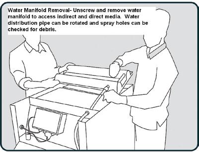
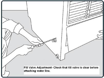
20 OASys SERVICING and MAINTENANCE DRAWINGS 19


21 OASys SERVICING and MAINTENANCE DRAWINGS continued 20


22 OASys SERVICING and MAINTENANCE DRAWINGS continued 21


23 OASys SERVICING and MAINTENANCE DRAWINGS continued SPEAKMAN CRS Clean Renewable Sustainable 22 #
Standard and CELDEK Evaporative Cooler Modules Installation, Operation, and Maintenance Manual
 Standard and CELDEK Evaporative Cooler Modules Installation, Operation, and Maintenance Manual Standard Evaporative Cooler CELDEK Evaporative Cooler RECEIVING AND INSPECTION Upon receiving unit, check
Standard and CELDEK Evaporative Cooler Modules Installation, Operation, and Maintenance Manual
 Standard and CELDEK Evaporative Cooler Modules Installation, Operation, and Maintenance Manual Standard Evaporative Cooler CELDEK Evaporative Cooler RECEIVING AND INSPECTION Upon receiving unit, check
CELDEK Evaporative Cooler Module Installation, Operation, and Maintenance Manual. CELDEK Evaporative Cooler
 CELDEK Evaporative Cooler Module Installation, Operation, and Maintenance Manual CELDEK Evaporative Cooler RECEIVING AND INSPECTION Upon receiving unit, check for any interior and exterior damage, and
Operation Manual SCT14B and SCT18B. Inspection. 3 General Description. 3 General Requirements. 3 Standard Features.
 Spot Cooling Systems, Inc. 120 Century Drive Suite 00 Carrollton, TX 7006 00-6-776 Operation Manual SCT1B and SCT1B Warning! Improper installation, adjustment, alteration, service, or maintenance can cause
Using the. Ducted Gas Central Heating Dual Cycle Refrigerated Air Conditioning Ducted Evaporative Air Conditioning. with your.
 Using the Ducted Gas Central Heating Dual Cycle Refrigerated Air Conditioning Ducted Evaporative Air Conditioning with your multi-appliance Touch Pad Control Owner s Manual Please keep this important manual
WIRING DIAGRAM. This manual describes the unit features and explains how to set-up, operate and maintain these AirPac Models. COOLIT2600 COOLIT2900
 WIRING DIAGRAM This manual describes the unit features and explains how to set-up, operate and maintain these AirPac Models. COOLIT2600 COOLIT2900 17 THANK YOU! WARRANTY INFORMATION Thank you for choosing
CROWN. Boiler Co. Santa-Fe Series. Hydronic Air Handlers INSTALLATION, OPERATION & MAINTENANCE INSTRUCTIONS
 CROWN Boiler Co Santa-Fe Series Hydronic Air Handlers INSTALLATION, OPERATION & MAINTENANCE INSTRUCTIONS These instructions must be affixed on or adjacent to the air handler Models: SAC049A20 SAC059A25
Model No.: PS08-01 PS10-01 Ref: KY80 KY100
 8,000/10,000/12,000 BTU Portable Air Conditioner Operating Instructions Model No.: PS08-01 PS10-01 Ref: KY80 KY100 Model No.: PS12-03 Ref: KY120 3119233 V160310 Thank you for choosing a Soleus Air Portable
Portable Air Conditioner 6,000 BTU 8,000 BTU 10,000 BTU
 Portable Air Conditioner 6,000 BTU 8,000 BTU 10,000 BTU OPERATING INSTRUCTIONS PCR-06-01 PCR-08-01 PCR-10-01 3058080 V170223 PURCHASE INFORMATION Thank you for choosing a Chigo Portable Air Conditioner.
5) Do not start or stop the unit by inserting or pulling out the power plug.
 Do not start or stop the unit by inserting or pulling out the power plug.") 3058080 V170306 PURCHASE INFORMATION Thank you for choosing a Soleus Air Portable Air Conditioner. This Owner s Manual will provide you with valuable information necessary for the proper care and maintenance
3058080 V170306 PURCHASE INFORMATION Thank you for choosing a Soleus Air Portable Air Conditioner. This Owner s Manual will provide you with valuable information necessary for the proper care and maintenance
CAREFULLY READ THESE INSTRUCTIONS BEFORE USING SAFETY PRECAUTIONS USE OF EXTENSION CORDS
 Owner s Manual CR2500ACH CR5000ACH Portable Heating and Air Conditioning Unit Version 02 Table of Contents 1. SAFETY INSTRUCTIONS... 1-1 CAREFULLY READ THESE INSTRUCTIONS BEFORE USING... 1-1 SAFETY PRECAUTIONS...
Installer s Guide CRS-2500 Single Packaged Two Stage Indirect-Direct Evaporative Cooler 2500 CFM (4250 CMH)
") Installer s Guide CRS-2500 Single Packaged Two Stage Indirect-Direct Evaporative Cooler 2500 CFM (4250 CMH) ALL phases of this installation must comply with NATIONAL, STATE AND LOCAL CODES Important This
Installer s Guide CRS-2500 Single Packaged Two Stage Indirect-Direct Evaporative Cooler 2500 CFM (4250 CMH) ALL phases of this installation must comply with NATIONAL, STATE AND LOCAL CODES Important This
CR13000-PAC OWNER S MANUAL. Portable Air Conditioner. PORTABLE AIR CONDITIONER with HEAT PUMP. Operating and Servicing Instructions
 OWNER S MANUAL Operating and Servicing Instructions CR13000-PAC PORTABLE AIR CONDITIONER with HEAT PUMP Portable Air Conditioner Questions or concerns? For assistance, please call Customer Service ClimateRight
RECOMMENDED LOCATION STEP BY STEP INSTALLATION. MODEL S 200P, 800BP and 97 POWER HUMIDIFIERS
 FOR USE WITH ALL FORCED AIR SYSTEMS SEQUENCE OF OPERATION The AUTOFLO Model s 200P, 800BP and 97 Humidifiers use the evaporative by-pass principal to add moisture into the return air duct of your central
Operation and Maintenance Manual 120V/60HZ
 Operation and Maintenance Manual 120V/60HZ GLACIER CS5-16-VD CS5-16-VD-TB CS5-18-VD CS5-18-VD-TB AVALANCHE CS6-36-1D CS6-36-VD BLIZZARD CS6-50-VD Operation & Maintenance Manual 60HZ Models Table of Contents:
OWNER S MANUAL DLFCAB / DLFCHB / DLFDAB / DLFDHB High Wall Ductless System Sizes 09 36
 OWNER S MANUAL DLFCAB / DLFCHB / DLFDAB / DLFDHB High Wall Ductless System Sizes 09 36 TABLE OF CONTENTS PAGE SAFETY PRECAUTIONS... 2 GENERAL... 2 INDOOR UNIT PART NAMES... 3 REMOTE CONTROL PART NAMES...
12,000 BTU Evaporative Portable Air Conditioner
 12,000 BTU Evaporative Portable Air Conditioner Owner s Manual Model # KY-32E Please read owner s manual carefully before operating the unit. TABLE OF CONTENTS PAGE Table of Contents. 2 Introduction....3
CAREFULLY READ THESE INSTRUCTIONS BEFORE USING SAFETY PRECAUTIONS USE OF EXTENSION CORDS
 Owner s Manual CR2500ACH CR5000ACH Portable Heating and Air Conditioning Unit Version 01 Table of Contents 1. SAFETY INSTRUCTIONS... 1-1 CAREFULLY READ THESE INSTRUCTIONS BEFORE USING... 1-1 SAFETY PRECAUTIONS...
Model 8191 & 8192 Ventilator with Dehumidification Installation and Operating Instructions
 Model 8191 & 8192 Ventilator with Dehumidification Installation and Operating Instructions ON/OFF button used to turn the ventilator on and off Up/Down buttons used to change humidity or vent time setting
Portable Room Air Conditioner and Heat Pump
 Installation, Operation & Maintenance Manual Portable Room Air Conditioner and Heat Pump PS-121B PSH-141A Thank you for purchasing our Portable Air Conditioner. French version of this manual is available
Model 8191 & 8192 Ventilator with Dehumidification Installation and Operating Instructions
 Model 8191 & 8192 Ventilator with Dehumidification Installation and Operating Instructions ON/OFF button used to turn the ventilator on and off Up/Down buttons used to change humidity or vent time setting
WCD-1. Evaporative Cooling Modules. WCD Series. Alton. Keeps You. Cool
 WCD-1 Evaporative Cooling Modules WCD Series Alton Keeps You Cool TURBOCELL WCD SERIES EVAPORATIVE COOLING MODULES THE LATEST IN COOLING TECHNOLOGY In many types of industries where efficient, low-cost
Operation and Maintenance Manual GLACIER TALL BASE CS5-16-VD-TB CS5-18-VD-TB2 120V/60HZ
 Operation and Maintenance Manual GLACIER TALL BASE CS5-16-VD-TB CS5-18-VD-TB2 120V/60HZ Operation & Maintenance Manual Table of Contents: 1.0 Introduction 1 2.0 Unpacking your COOL- SPACE 1 3.0 Set-up
installation and start-up instructions HUMIDIFIERS AND HUMIDISTAT
 installation and start-up instructions HUMIDIFIERS AND HUMIDISTAT HUM Cancels: II 912D-56-3 II HUM-56-1 7-98 MODEL HUMBBLFP1025-A-- FAN-POWERED HUMIDIFIER MODEL HUMBBLBP2018-A-- BYPASS HUMIDIFIER MODEL
Operation and Maintenance Manual BLIZZARD50 CS6-50-VD 120V/60HZ
 Operation and Maintenance Manual BLIZZARD50 CS6-50-VD 120V/60HZ CS6-50-VD Operation & Maintenance Manual Table of Contents: 1.0 Introduction 1 2.0 Unpacking your COOL- SPACE 1 3.0 Set-up of COOL-SPACE
Operating Instructions
 PH5-13R-35D Portable Air Conditioner with Heat Pump Operating Instructions 3092402 Item Number: LX-130 Model Number: PH5-13R-35D 201 Soleus Air International Thank you for choosing a Soleus Air PH5 Series
Use and Care Manual. MODELS H VAR 1.5 THRU 5 TON 13 Seer Split System Heat Pump REV. 4/06
 Use and Care Manual MODELS H1318-601VAR 1.5 THRU 5 TON 13 Seer Split System Heat Pump REV. 4/06 0010577104 Table of Contents: INTRODUCTION Introduction 1 How Your System Works 1 Operation Instructions
Fully-automatic Gas tankless Water Heater USER'S MANUAL FOR MODEL EZ-101 ISO9001 certified
 Fully-automatic Gas tankless Water Heater USER'S MANUAL FOR MODEL EZ-101 ISO9001 certified Thank you for purchasing our fully-automatic gas-fired tankless water heater. Please completely read this Manual
14,000 BTU Portable Air Conditioner 14,200 BTU Heat Pump Model Number: LX-140 Operating Instructions. Model No. LX Soleus Air International
 14,000 BTU Portable Air Conditioner 14,200 BTU Heat Pump Model Number: LX-140 Operating Instructions 3092402 Model No. LX-140 2012 Soleus Air International Thank you for choosing a Soleus Air LX-140 Portable
RSIF power venter USA CAN READ AND SAVE THESE INSTRUCTIONS! Installation and operation manual. Product information Chapters 1 + 2
 3002239 RSIF 2014-04-04 Installation and operation manual RSIF power venter READ AND SAVE THESE INSTRUCTIONS! Product information Chapters 1 + 2 Mechanical installation Chapter 3 Electrical installation
Portable Air Conditioner with Heat Pump Technology Operating Instructions. Model No.: HCB-P13HP-D. Reference No.: BPD13HP V140217
 Portable Air Conditioner with Heat Pump Technology Operating Instructions 3092402 Model No.: HCB-P13HP-D Reference No.: BPD13HP V140217 Thank you for choosing a Soleus Air Portable Air Conditioner with
Portable Air Conditioner with Heat Pump Technology PH4-10R-01, PH4-12R-01, & PH4-14R-01 Operating Instructions
 Portable Air Conditioner with Heat Pump Technology PH4-10R-01, PH4-12R-01, & PH4-14R-01 Operating Instructions 3092402 2006 Soleus Air International Thank you for choosing a Soleus Air Portable Air Conditioner
HUMIDIFIERS OWNERS MANUAL A GUIDE TO OPERATING AND MAINTAINING YOUR HUMIDIFIER 49FH, 49FP, 49BF, 49WS, & 49BG
 49FH, 49FP, 49BF, 49WS, & 49BG HUMIDIFIERS READ AND SAVE THESE INSTRUCTIONS Model 49FH Fan-Powered A95248 Model 49FP Fan-Powered A95249 Model 49BF Bypass A95250 Model 49WS Water-Saver Bypass A95251 Model
Model 1750A/ 1770A Dehumidifier Installation Instructions
 Model 1750A/ 1770A Dehumidifier Installation Instructions Safety Instructions WARNING 1. Improper installation may cause property damage or injury. Installation, service, and maintenance must be performed
Residential Steam Humidifier
 Residential Steam Humidifier Model HUMXXSTM3034 Residential Steam Humidifier Owner s Manual Includes Safety & Operating Instructions READ AND SAVE THESE INSTRUCTIONS TABLE OF CONTENTS Safety... 2 Introduction...
OPERATING INSTRUCTIONS
 COMFORT CONTROL CENTER 2 THERMOSTAT OPERATING INSTRUCTIONS PROGRAMMABLE THERMOSTAT MODEL 3314080.000 BLACK 3314080.015 WHITE USA SERVICE OFFICE Dometic Corporation 1120 North Main Street Elkhart, IN 46514
INSTALLATION INSTRUCTIONS FMB/FMC SERIES MULTI-POSITION AIR HANDLER
 ASPEN MANUFACTURING 373 ATASCOCITA RD. HUMBLE, TX 77396 TEL (281) 441-6500 FAX (281) 441-6510 > INSTALLATION INSTRUCTIONS FMB/FMC SERIES MULTI-POSITION AIR HANDLER IMPORTANT: "The
OPERATION MANUAL. Move it. Hang it. Rack it. Stack it. MaxPower Corporation 230 Yuma Street Denver, CO
 OPERATION MANUAL Complete Instructions for and Operation MaxPower Corporation 230 Yuma Street Denver, CO 80223 800-576-3966 www.coolcube10.com Move it. Hang it. Rack it. Stack it. 05/05 P/N: 5-TC600-2510
40KMC KMQ
 40KMC------301 40KMQ------301 OWNER S MANUAL Split system Global cassette indoor unit IR Remote Control Room Controller Zone Manager The unit can be used with infrared Remote Control, with the Carrier
I.O.M. #116 7/10 INSTRUCTION MANUAL INSTALLATION OPERATION MAINTENANCE. Covers Models from 25 to 100 tons.
 I.O.M. #6 7/0 INSTRUCTION MANUAL INSTALLATION OPERATION MAINTENANCE Covers Models from 25 to 00 tons. 525 East Stop 8 Road Greenwood, IN 4642 37-887-0729 fa: 37-88-277 Service Department fa: 37-885-8683
Bedroom 100. True or False: Space heaters are more energy efficient and inexpensive to heat large areas than central heating systems.
 Bedroom 100 True or False: Space heaters are more energy efficient and inexpensive to heat large areas than central heating systems. Bedroom 200 Insulation: A) Facilitates the exchange of air from external
MODEL 598A TWO-SPEED PLUS CENTRAL AIR CONDITIONER
 USER S INFORMATION MANUAL MODEL 598A TWO-SPEED PLUS CENTRAL AIR CONDITIONER NOTE TO INSTALLER: This manual must be left with the equipment user. WELCOME TO EFFICIENT HOME COOLING COMFORT Congratulations
RV Products Division INSTALLATION INSTRUCTIONS FOR SERIES PACKAGE AIR CONDITIONER
 RV Products Division INSTALLATION INSTRUCTIONS FOR 46413 SERIES PACKAGE AIR CONDITIONER 1. WARNINGS IMPORTANT NOTICE These instructions are for the use of qualified individuals specially trained and experienced
AUTOMATIC MAKE-UP AIR DAMPER WITH TRANSFORMER READ AND SAVE THESE INSTRUCTIONS
 AUTOMATIC MAKE-UP AIR DAMPER WITH READ AND SAVE THESE INSTRUCTIONS FOR RESIDENTIAL USE ONLY Page 1 WARNING TO REDUCE THE RISK OF FIRE, ELECTRIC SHOCK, OR INJURY TO PERSONS, OBSERVE THE FOLLOWING: 1. Installation
INSTALLATION INSTRUCTIONS FOR 6532 SERIES PACKAGE HEAT PUMP
 INSTALLATION INSTRUCTIONS FOR 6532 SERIES PACKAGE HEAT PUMP RV Products A Division of Airxcel, Inc. P.O. Box 4020 Wichita, KS 67204 1976-360 (1-02) PP TABLE OF CONTENTS 1. Warnings......................................................
RSIF Power Venter USA CAN. Product Information. ... Chapters Mechanical Installation. ... Chapter 3. Electrical Installation. ...
 Installation & Operating Manual RSIF Power Venter USA CAN Product Information... Chapters 1 + 2 Mechanical Installation... Chapter 3 Electrical Installation... Chapter 4 Start Up and Configuration... Chapter
HE420A,B and HE460A,B Steam Power Humidifiers OWNER S GUIDE
 HE420A,B and HE460A,B Steam Power Humidifiers OWNER S GUIDE U.S. Registered Trademark Copyright 1998 Honeywell Inc. All Rights Reserved 69-1112-1 WELCOME... to the comfortable world of humidified air.
12,000 BTU Portable Air Conditioner PE3-12R-03. Model No. PE3-12R Soleus Air International
 12,000 BTU Portable Air Conditioner Operating PE3-12R-03 Instructions 3092402 Model No. PE3-12R-03 2010 Soleus Air International Thank you for choosing a Soleus Air PE3-12R-03 Portable Air Conditioner.
Healthy Climate Whole-Home Dehumidifier. Nominal Capacity - 70 to 130 pints per day INDOOR AIR QUALITY HCWHD PRODUCT SPECIFICATIONS.
 PRODUCT SPECIFICATIONS INDOOR AIR QUALITY HCWHD Healthy Climate Whole-Home Dehumidifier Bulletin No. 210699 November 2017 Supersedes April 2017 MODEL NUMBER IDENTIFICATION Nominal Capacity - 70 to 130
INSTALLATION INSTRUCTIONS FMB/FMC SERIES MULTI-POSITION AIR HANDLER
 INSTALLATION INSTRUCTIONS FMB/FMC SERIES MULTI-POSITION AIR HANDLER IMPORTANT MASSAGE TO INSTALLER: "The United States Environmental Protection Agency ("EPA") has issued various regulations regarding the
Desiccant Dehumidifier
 Since the 1950s Desiccant Dehumidifier Dry Spaces With NO Added Heat BMIL Technologies, LLC 4915 Arendell St., #313 Morehead City, NC 28557 PH 252-727-0994 FAX 252-727-0996 WWW.BMIL.COM Product Description
Oil Furnace USER S INFORMATION MANUAL FOR THE OPERATION AND MAINTENANCE OF YOUR NEW OIL-FIRED FURNACE
 Oil Furnace USER S INFORMATION MANUAL FOR THE OPERATION AND MAINTENANCE OF YOUR NEW OIL-FIRED FURNACE MODEL PO8LAA LOW-BOY NOTE TO INSTALLER: THIS MANUAL MUST BE LEFT WITH THE EQUIPMENT USER. MODEL PO8UAA
USER S MANUAL AND INSTALLATION INSTRUCTIONS IMPORTANT
 USER S MANUAL AND INSTALLATION INSTRUCTIONS P3BD Series 13 SEER Single Package Air Conditioner IMPORTANT Read this owner information to become familiar with the capabilities and use of your appliance.
Owner s Manual TABLE OF CONTENTS
 40MBDQ Ducted Style Ductless System Sizes 18 to 48 Owner s Manual TABLE OF CONTENTS PAGE A NOTE ABOUT SAFETY... 2 GENERAL... 2 PARTS LIST... 3 DISPLAY PANELS... 4 FUNCTION BUTTONS... 5 REMOTE CONTROL...
Packaged Gas/Electric Units. Owner s Guide to Operating and Maintaining Your Gas/Electric Unit
 Packaged Gas/Electric Units Owner s Guide to Operating and Maintaining Your Gas/Electric Unit ELECTRICAL SHOCK HAZARD. FIRE OR EXPLOSION HAZARD Disconnect power at fuse box or service panel before performing
Portable Air Conditioner Instruction Manual
 Portable Air Conditioner Instruction Manual WA-1240AE1: 12,000BTU (cooling only) WA-1240H1: 12,000BTU (cooling & heating) WA-1420E1: 14,000BTU (cooling only) WA-1420H1: 14,000BTU (cooling & heating) Thank
Installation Instructions Owner s Manual
 Installation Instructions Owner s Manual FOR USE WITH GAS, OIL and HYDRONIC FORCED AIR FURNACES SEQUENCE OF OPERATION The AUTOFLO Model s SC15 & 250 use the evaporative principal to add moisture to the
2003 METAL FORM MFG. FORM NO: PCIOM/03
 PRECOOLER PRE-CONDENSER EVAPORATIVE COOLERS Installation, Operation, and Maintenance Manual Energy Saver (ES) has a policy of continuous product improvement and reserves the right to change designs and
KINGS COUNTY JAIL EXPANSION PHASE III COUNTY OF KINGS SECTION
 SECTION 237433, PART 1 - GENERAL 1.1 RELATED DOCUMENTS A. Drawings and general provisions of the Contract, including General and Supplementary Conditions and Division 01 Specification Sections, apply to
PAC12J. 12,000btu Cool & Heat Portable Air Conditioner. Please read this manual carefully prior to operating the product.
 USER MANUAL Portable Air Conditioner and Heater With Heat Pump Technology PAC12J 12,000btu Cool & Heat Portable Air Conditioner Please read this manual carefully prior to operating the product. Please
INSTALLATION INSTRUCTIONS FOR 6536 SERIES TWO TON PACKAGED HEAT PUMP
 INSTALLATION INSTRUCTIONS FOR 6536 SERIES TWO TON PACKAGED HEAT PUMP TABLE OF CONTENTS 1. Warnings...2 2. Component Match-Up...2 3. Unit Depiction Figures...3 4. Blower Performance Data...5 5. General
NOTE: All the illustrations in this manual are for explanation purposes only. Your air conditioner may be slightly different.
 RADS-51J RADS-61J Owner s Manual Room Air Conditioner with R-410A Heat Controller, Inc. 15 16 Contact an authorized service technician for repair or maintenance of this unit. Contact an authorized installer
August 15, 2013 Page 1 of 19
 Section C401 Application Compliance with C402, C403, C404 and C405 AND (either C406.2, C406.3 or C406.4) Compliance with C402, C403, C404 or C405 Section C402 Building Envelope (Climate Zone 5A) Space-Conditioning
Owner's Manual TABLE OF CONTENTS
 40MAQ High Wall Ductless System Sizes 09 to 36 Owner's Manual TABLE OF CONTENTS PAGE A NOTE ABOUT SAFETY... 2 GENERAL... 2 PART NAMES... 3 FUNCTION BUTTONS... 4 DISPLAY PANELS... 5 REMOTE CONTROL... 6
Digi-Zone. Installation and Operating Instructions. Model MDP3. Controlling Your Comfort Room By Room
 Digi-Zone Model MDP3 Installation and Operating Instructions Controlling Your Comfort Room By Room System Indicator LEDs MDP3 Panel Features Power Indicator LED Leaving & Outdoor Air Sensors Zone Terminals
BESF Box Ventilator USA CAN. Product Information. Mechanical Installation. ... Chapter 3. Electrical Installation. ... Chapter 4
 Installation & Operating Manual BESF Box Ventilator USA CAN Product Information... Chapter 1 + 2 Mechanical Installation... Chapter 3 Electrical Installation... Chapter 4 Start Up and Configuration...
INSTALLATION INSTRUCTIONS & HOME OWNERS MANUAL ECO 18 ECO 24 ECO 27 IMPORTANT SAFETY INFORMATION
 INSTALLATION INSTRUCTIONS & HOME OWNERS MANUAL ECO 18 ECO 24 ECO 27 IMPORTANT SAFETY INFORMATION As when installing or using any high voltage electrical appliance, basic safety precautions should always
EcoCooler Legionella Risk Assessment Information Pack
 EcoCooler Legionella Risk Assessment Information Pack Purpose of Document This information in this document is intended to provide a basis for the understanding of the risk of Legionnaires disease in EcoCooling
Peachtree City is home office for America located about 30 miles south of the Atlanta airport this is were all KM cubers as well as Flakers are built.
 The following slides are designed to give you good understanding of the KM sequence of operation. You will find the sequence explained in two ways the first is a basic explanation that goes along with
INSTALLATION INSTRUCTIONS FOR MOUNTING KIT
 RV Products Division INSTALLATION INSTRUCTIONS FOR 8330-5501 MOUNTING KIT 8330-752 CONTROL BOX KIT (12 VDC COOL ONLY) 9330B755 CONTROL BOX KIT (12 VDC HEAT/COOL) 8530-750 CONTROL BOX KIT (24 VAC COOL ONLY)
INSTRUCTIONS OPERATING BLUETOOTH CAPACITIVE TOUCH THERMOSTAT MODEL COOL/FURNACE COOL/FURNACE/HEAT PUMP
 BLUETOOTH CAPACITIVE TOUCH THERMOSTAT OPERATING INSTRUCTIONS 3316420.XXX MODEL COOL/FURNACE COOL/FURNACE/HEAT STRIP COOL/FURNACE/HEAT PUMP Read these instructions carefully. These instructions MUST stay
CENTRAL AIR CONDITIONER
 USER S INFORMATION MANUAL CENTRAL AIR CONDITIONER NOTE TO INSTALLER: This manual must be left with the equipment user. WELCOME TO EFFICIENT HOME COOLING COMFORT Congratulations on your excellent choice
17 Interior Climate Control
 17 Interior Climate Control 17.1 Air is leaking through or around windows and/or exterior doors. Windows and doors shall be installed to minimize air leakage in accordance with the Alberta Building Code.
OWNER'S MANUAL R-410A Duct Free Split System Air Conditioner and Heat Pump
 R-10A Duct Free Split System Air Conditioner and Heat Pump Product Family: DFF(A/H)H, DFC(A/H) Please read the operating instructions and safety precautions carefully and thoroughly before installing and
11,000 BTU Portable Air Conditioner with dehumidifier & Fan PE4-11R-03 Operating Instructions. Model No. PE4-11R Soleus Air International
 11,000 BTU Portable Air Conditioner with dehumidifier & Fan PE4-11R-03 Operating Instructions Model No. PE4-11R-03 2006 Soleus Air International Thank you for choosing a Soleus Air Portable Air Conditioner.
MODEL HUM HUMIDIFIERS
 HOMEOWNER S MANUAL MODEL HUM HUMIDIFIERS Model HUMBBLFP1025-A-- Fan-Powered Humidifier Model HUMBBSFP1016-A-- Fan-Powered Humidifier Model HUMBBLBP2018-A-- Bypass Humidifier Model HUMBBSBP2017-A-- Bypass
Your safety and the safety of others are very important.
 VARIABLE SPEED ELECTRIC FURNACE INSTALLATION INSTRUCTIONS VARIABLE SPEED ELECTRIC FURNACE SAFETY...1 INSTALLATION REQUIREMENTS...2 Tools and Parts...2 Location Requirements...2 Installation Configurations...3
Digi-Zone Model MDP3 Ver.04
 Digi-Zone Model MDP3 Ver.04 Installation and Operating Instructions Controlling Your Comfort Room By Room System Indicator LEDs MDP3 Panel Features Power Indicator LED Leaving & Outdoor Air Sensors Zone
Manual update 2016 MC37/MFC3600
 Manual update 2016 MC37/MFC3600 SETUP INSTRUCTIONS Evaporative cooling works on the principle of heat absorption by moisture evaporation. Simply put, heat is removed from the air as water evaporates. You
BESB Box Ventilator USA CAN. Product Information. Mechanical Installation. ... Chapter 3. Electrical Installation. ... Chapter 4
 Installation & Operating Manual BESB Box Ventilator USA CAN Product Information... Chapter 1 + 2 Mechanical Installation... Chapter 3 Electrical Installation... Chapter 4 Start Up and Configuration...
SAFETY AND INSTALLATION MANUAL MODEL 8100
 SAFETY AND INSTALLATION MANUAL ENERGY RECOVERY VENTILATORS MODEL 8100 Provides year-round fresh air Recovers 77% of the apparent heating or cooling energy from the exhausted air See Warnings Page 3 Table
Window Type Air Conditioner
 Window Type Air Conditioner Owner's Manual Residential Air Conditioner Models: IWA-06CP, IWA-08CP, IWA-10CP, IWA-12CP Thank you for choosing Residential Air Conditioners, please read this owner s manual
Manual for MC37/MFC3600
 Manual for MC37/MFC3600 SETUP INSTRUCTIONS Evaporative cooling works on the principle of heat absorption by moisture evaporation. Simply put, heat is removed from the air as water evaporates. You feel
OWNER S MANUAL HIGH WALL INVERTER. (English) (BSHVD1S SERIES)
 (BSHVD1S SERIES)") OWNER S MANUAL HIGH WALL INVERTER (English) (BSHVD1S SERIES) IMPORTANT As with any product that has moving parts or is subject to wear and tear, it is VERY IMPORTANT that you maintain your air conditioner
OWNER S MANUAL HIGH WALL INVERTER (English) (BSHVD1S SERIES) IMPORTANT As with any product that has moving parts or is subject to wear and tear, it is VERY IMPORTANT that you maintain your air conditioner
FLOW-THROUGH FURNACE HUMIDIFIER
 FLOW-THROUGH FURNACE HUMIDIFIER Installation Warranty Maintenance Troubleshooting Guide 2 Installation READ COMPLETE INSTALLATION INSTRUCTIONS AND TEMPLATE BEFORE STARTING Attention Installer: Installation
Specifications 3. Bladder 5. Chimney 12. Air Supply 12. Anti-Rollout Device and Ash Auger Tube 14. Timer 15
 TABLE OF CONTENTS Page No. Specifications 3 Bladder 5 Fire Door 7 Chimney 12 Air Supply 12 Anti-Rollout Device and Ash Auger Tube 14 Timer 15 Supply Line and Return Line Threaded Connectors 15 Low Water
COMPACT PORTABLE AIR CONDITIONER USER MANUAL
 COMPACT PORTABLE AIR CONDITIONER USER MANUAL Thank you for choosing ElectriQ Please read this user manual before using this innovative Air Conditioner and keep it safe for future reference. Visit our page
INSTALLATION AND OPERATION MANUAL STEAM COIL BASE CONVECTION STEAMER MODEL SCX-16
 INSTALLATION AND OPERATION MANUAL STEAM COIL BASE CONVECTION STEAMER MODEL SCX-16 CROWN FOOD SERVICE EQUIPMENT LTD. 70 OAKDALE ROAD, DOWNSVIEW, (TORONTO), ONTARIO, CANADA, M3N 1V9 TELEPHONE: (416) 746-2358,
CMHC HOME MAINTENANCE CHECKLIST
 Make sure air vents indoors and outdoors (intake, exhaust and forced air) are not blocked by snow or debris. Check and clean range hood filters on a monthly basis. Test ground fault circuit interrupter(s)
OPERATING & MAINTENANCE MANUAL HORIZONTAL WATER SOURCE HEAT PUMP. World class comfort.
 OPERATING & MAINTENANCE MANUAL HORIZONTAL WATER SOURCE HEAT PUMP World class comfort. welcome Congratulations on your selection of Ice Air Water Source Heat Pumps (WSHPs) for your comfort conditioning
INSTALLATION INSTRUCTIONS FOR 8330*5511 MOUNTING KIT
 RV Products Division INSTALLATION INSTRUCTIONS FOR 8330*5511 MOUNTING KIT 8330-752 CONTROL BOX KIT (12 VDC COOL ONLY) 9330A755 CONTROL BOX KIT (12 VDC HEAT/COOL) 8530-750 CONTROL BOX KIT (24 VAC COOL ONLY)
UNDERCOUNTER LABORATORY REFRIGERATORS and FREEZERS Installation, Operation and Maintenance Instructions
 UNDERCOUNTER LABORATORY REFRIGERATORS and FREEZERS Installation, Operation and Maintenance Instructions INSPECTION When the equipment is received, all items should be carefully checked against the bill
H32 Uni- Zone Model H32
 H32 Uni- Zone Model H32 Installation and Operating Instructions Controlling Your Comfort Room By Room F o l l o w u s o n H32 PANEL FEATURES System Mode Indicator LED Power Indicator LED HVAC Equipment
Owner's Manual TABLE OF CONTENTS
 40MB*D Ducted Style Ductless System Sizes 09 to 48 Owner's Manual TABLE OF CONTENTS PAGE A NOTE ABOUT SAFETY... 2 GENERAL... 2 PARTS LIST... 3 DISPLAY PANELS... 4 FUNCTION BUTTONS... 5 REMOTE CONTROL...
Dehumidifier Owner s Manual Read and save these instructions before use
 Dehumidifier Owner s Manual Read and save these instructions before use Model: DH45W For product inquiries or support: www.jmatek.com Customer Support: 1-800-474-2147 E-mail us at: usinfo@jmatek.com ERGY
Model No. GB-PAC-08E4. 8,000 BTU Portable Air Conditioner Operating Instructions
 Model No. GB-PAC-08E4 8,000 BTU Portable Air Conditioner Operating Instructions Thank you for choosing a Soleus Air Powered by Gree Portable Air Conditioner. This owner s manual will provide you with valuable
EVAPORATIVE AIR COOLER SERVICE MANUAL
 EVAPORATIVE AIR COOLER SERVICE MANUAL CAUTION: Before servicing the unit, read the Safety Precautions in this manual. Only for authorized service. MODEL NO.: CL30XC & CHL30XC (INDOOR USE ONLY) CONTENT
Portable Air Conditioner, Dehumidifier,Heater and Fan utilizing Heat Pump Technology
 Portable Air Conditioner, Dehumidifier,Heater and Fan utilizing Heat Pump Technology OWNER'S MANUAL Model # KY-34 3046364 Please read owner s manual carefully before operating unit. TABLE OF CONTENTS INTRODUCTION...3
Packaged Gas/Electric
 Packaged Gas/Electric Units Owner's Guide to Operating and Maintaining Your Gas/Electric Unit ELECTRICAL SHOCK HAZARD. FIRE OR EXPLOSION HAZARD Failure to follow this warning can result in Disconnect power
BESF Box Ventilator. Installation & Operating Manual USA CAN READ AND SAVE THESE INSTRUCTIONS
 Installation & Operating Manual 3001806 03.02 USA CAN BESF Box Ventilator READ AND SAVE THESE INSTRUCTIONS 1200 Northmeadow Parkway, STE 180 Roswell, GA 30076 (770) 587-3238 (800) 255-2923 Fax (770) 587-4731