Unichiller V Operation Manual
|
|
|
- August Sims
- 6 years ago
- Views:
Transcription

1 Unichiller V2.2.0 Operation Manual
2

3 OPERATION MANUAL Unichiller V2.2.0
4
5 OPERATION MANUAL Unichiller Pilot ONE This operation manual is a translation of the original operation manual. Also for models with heater and with/without an emergency stop switch (optional). VALID FOR: Unichiller 0xxT Unichiller 1x0T Unichiller 2x0T Unichiller 3x0T Unichiller 400T Unichiller 500T Unichiller 600T Unichiller 700T Abbreviations used in model names: Without = with air cooling, P = stronger Pump, w = with water cooler V2.2.0en/ //15.09 Unichiller 5
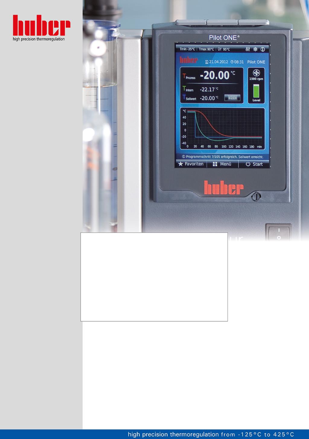
6 OPERATION MANUAL Pilot ONE Layout of the Home screen 6 Unichiller V2.2.0en/ //15.09
7 OPERATION MANUAL Table of contents V2.2.0en/ // Introduction Details on the declaration of conformity Safety Symbols used for Safety Instructions Proper operation Reasonably foreseeable misuse Responsible bodies and operators Obligations and requirements Obligations of the responsible body Proper disposal of resources and consumables Temperature control unit with natural refrigerants (NR) Temperature control units with fluorinated greenhouse gases/refrigerants Requirements for operators Obligations of the operators General information Description of workstation Safety devices to DIN Temperature control units (with heater) with electronic low level sensor Further protective devices Power interruption Alarm functions Warning messages Emergency stop switch (optional) Exemplary illustrations of the cooling variants Air cooling Water cooling Consequence of inadequate energy dissipation Commissioning In-plant transport Lifting and transporting the temperature control unit Temperature control unit with lifting eyes Temperature control unit without lifting eyes Positioning the temperature control unit Temperature control unit with casters Temperature control unit without casters Transportation lock Transportation lock Type A Releasing the transportation lock (operating position) Tightening the transportation lock (transport position) Transportation lock Type B Releasing the transportation lock (operating position) Tightening the transportation lock (transport position) Unpacking Ambient conditions EMC-specific notes Installation conditions Temperature control unit for outdoor installation incl. winter operation V2.2.0en/ //15.09 Unichiller 7
8 OPERATION MANUAL 2.7 Recommended temperature control and cooling water hoses Wrench sizes and torques Temperature control units with water cooling Preparations for operation Unscrewing/activating the leveling feet (if any) Opening/closing valves Emergency stop switch (optional): Check switching status Connecting externally closed application Connecting an externally closed application Connecting to the power supply Connection using socket with protective earth (PE) Connection via hard wiring Connecting the functional earth Function description Function description of the temperature control unit General functions Other functions Information on the thermal fluids To be noted when planning the test Pilot ONE controller Functional overview of Pilot ONE Clock/event function Rechargeable accumulator Programmable event function Event function Alarm clock event Event function Program event Operation via the touch screen Display instruments The touchscreen [88] Control instruments The touchbuttons The categories The sub-categories The dialogs Function examples Display of software version Start & Stop Copying the settings to a data carrier Saving to a USB flash drive Loading from a USB flash drive Restore factory settings Restore to factory settings without overtemperature protection Restore to factory settings including overtemperature protection Unichiller 4 Setup mode Setup mode Emergency stop switch (optional): Activate / Deactivate Emergency stop switch (optional): Activate Emergency stop switch (optional): Deactivate Turning on the temperature control unit Setting the overtemperature protection General information on the overtemperature protection V2.2.0en/ //15.09
9 OPERATION MANUAL Setting OT limit: heating Setting Process Safety Monitoring via Display OT values Testing overtemperature protection for functionality Adjusting the Delta T limiter Changing the Delta T limiter The temperature control circuit Select temperature control: Internal or process Temperature control to internal temperature Temperature control to process temperature Delta T limiter Monitoring the Pt100 temperature sensors Optimum control parameters for optimum temperature control Sub-category: Select auto/expert mode Sub-category: Configuration auto Sub-category: Find parameters Sub-category: Control Dynamics Sub-category: Fluid Properties Sub-category: Display parameters Sub-category: Configuration manual Sub-category: Change parameters Sub-category: Display parameters Sub-category: Control structure Sub-category: Reset parameters Sub-category: Display parameters Freeze protection for temperature control unit (optional) Setting the setpoint thresholds Setting the setpoint Filling, venting and draining Externally closed application Filling and venting externally closed application Draining externally closed applications Normal operation Automatic operation Temperature control Starting the temperature control process Ending the temperature control process Temperature control via a created temperature control program Starting the temperature control program Ending/cancelling the temperature control program Interfaces and software update Interfaces at the Pilot ONE controller /100 Mbps Ethernet for RJ45 network sockets USB-2.0 interface USB-2.0 interface, host USB-2.0 interface, device Interfaces at the top side of the Unichiller Female RS232 Serial (with adapter cable) Connection jack for Pt100 process controller sensor Service interface Interfaces at the Com.G@te (optional) V2.2.0en/ //15.09 Unichiller 9
10 OPERATION MANUAL Jack LEVEL external only) Connector POKO (floating contact) alarm Jack AIF Reg-E-Prog Jack ECS (External Control Signal) standby Jack RS232/RS485 serial Firmware update Service/maintenance Messages from the temperature control unit Replacing the Pilot ONE Maintenance Function check and visual inspection Replacing temperature control or coolant hoses Replacing temperature control hoses Replacing coolant hoses Clean liquefier fins (air-cooled temperature control unit) Clean hat-type strainer (dirt trap) (water-cooled temperature control unit) Emergency stop switch (optional): Function test Thermal fluid inspection, replacement and circuit cleaning Thermal fluid inspection Thermal fluid replacement Externally closed application Rinsing the thermal fluid circuit Cleaning the surfaces Inspect the mechanical seal Plug contacts Decontamination/repairs Shutting down Safety instructions and basic principles Switch-off Draining the cooling water Draining process Transportation lock Packing Shipping Disposal Phone number and company address Telephone number: Customer Support Telephone number: Sales address: Customer Support Service/return address Certificate of Compliance Annex Unichiller V2.2.0en/ //15.09
11 OPERATION MANUAL Foreword Dear Customer, Thank you for choosing a temperature control unit from Peter Huber Kältemaschinenbau AG. You have made a good choice. Thank you for your trust. Please read the operation manual carefully before putting the unit into operation. Strictly follow all notes and safety instructions. Follow the operation manual with regard to transport, start-up, operation, maintenance, repair, storage and disposal of the temperature control unit. We fully warrant the temperature control unit for the specified normal operation. The models listed on page 5 are referred to in this operation manual as temperature control units and Peter Huber Kältemaschinenbau AG as Huber company or Huber. Liability for errors and misprints excluded. The following trademarks and the Huber logo are registered trademarks of Peter Huber Kältemaschinenbau AG in Germany and/or other countries worldwide: BFT, CC, CC-Pilot, Com.G@te, Compatible Control, CoolNet, DC, E-grade, Grande Fleur, KISS, Minichiller, Ministat, MP, MPC, Peter Huber Minichiller, Petite Fleur, Pilot ONE, RotaCool, Rotostat, SpyControl, SpyLight, Tango, TC, UC, Unical, Unichiller, Unipump, Unistat, Unistat-Pilot, Unistat Tango, Variostat, Web.G@te. The following trademarks are registered in Germany to DWS Synthesetechnik: DW-Therm, DW-Therm HT V2.2.0en/ //15.09 Unichiller 11
12 Introduction OPERATION MANUAL Chapter 1 1 Introduction 1.1 Details on the declaration of conformity The equipment complies with the basic health and safety requirements of the European Directives listed below: Machinery Directive 2006/42/EC Low Voltage Directive 2006/95/EC EMC Directive 2004/108/EC 1.2 Safety Symbols used for Safety Instructions Safety instructions are marked by the below combinations of pictograms and signal words. The signal word describes the classification of the residual risk when disregarding the operation manual. Denotes an immediate hazardous situation that will result in death or serious injuries. Denotes a general hazardous situation that may result in death or serious injuries. Denotes a hazardous situation that can result in injury. Denotes a situation that can result in property material damage. Denotes important notes and usable hints. Notes in conjunction with Ex p cabinets. Safety information and procedure The safety information in this operation manual is designed to protect the responsible body, operator and the equipment from damage. Safety information must always appear BEFORE instructions and at the beginning of each chapter. You should be first informed about the residual risks due to misuse before you begin an operation. 12 Unichiller V2.2.0en/ //15.09
13 Introduction Chapter 1 OPERATION MANUAL Proper operation Operating the temperature control unit in a potentially explosive area DEATH THROUGH EXPLOSION Do NOT install or start up the temperature control unit within an ATEX zone. Improper use SERIOUS INJURY AND PROPERTY DAMAGE Store the operation manual where it is easy to access in close proximity to the temperature control unit. Only adequately qualified operators may work with the temperature control unit. Operators must be trained before handling the temperature control unit. Check that the operators have read and understood the operation manual. Define precise responsibilities of the operators. Personal protective equipment must be provided to the operators. Be sure to follow the responsible body s safety rules to protect life and limb and to limit damages! Modifications to the temperature control unit by third-parties DAMAGE TO THE TEMPERATURE CONTROL UNIT Do not allow third parties to make technical modifications to the temperature control unit. In case of any modification of the temperature control unit not approved by the manufacturer, the CE declaration of conformity becomes invalid. Only specialists trained by the manufacturer may carry out modifications, repairs or maintenance work. The following must be observed without fail: Only use the temperature control unit in a fault-free condition! Have start-up and repairs carried out only by specialists! Do not ignore, bypass, dismantle or disconnect any safety devices! The temperature control unit must not be used for any purposes other than temperature control in accordance with the operation manual. The temperature control unit is manufactured for industrial use. The temperature control unit maintains the temperature of certain applications, including glass or metal reactors or other expedient items in laboratories and industry. Flow-through coolers and calibration baths must be used only in combination with Huber temperature control units. Thermal fluids suitable for the overall system are used. The chilling and heating capacity is provisioned at the pump connections or - where present - in the tempering bath. The technical specification of the temperature control unit is given in the data sheet (from page 81 in section»annex«). The temperature control unit must be installed, configured and operated according to the handling instructions in this operating manual. Failure to comply with the operation manual is deemed improper use. The temperature control unit conforms to state-of-the-art technology and the recognized safety regulations. Safety devices are built into your temperature control unit Reasonably foreseeable misuse Without an Ex p cabinet, the temperature control unit is NOT protected against explosion and must NOT be installed or put into operation within an ATEX Zone. When operating the temperature control unit in conjunction with an Ex p cabinet, the information in the annex (Section ATEX operation) must be observed and followed. This annex is only provided for temperature control units delivered with an Ex p cabinet. If this annex is missing, please immediately contact the Customer Support of Huber (the telephone number is provided on page 80 in Section»Phone number and company address«). Use with medical devices (e.g. in Vitro diagnostic procedure) or for direct foodstuff temperature control is NOT permissible. The temperature control unit must NOT be used for any purposes other than temperature control in accordance with the operation manual. The manufacturer accepts NO liability for damage caused by technical modifications to the temperature control unit, improper handling or use of the temperature control unit if the operation manual is not observed. V2.2.0en/ //15.09 Unichiller 13
14 Introduction OPERATION MANUAL Chapter Responsible bodies and operators Obligations and requirements Obligations of the responsible body The operation manual is to be stored where it is easy to access in close proximity to the temperature control unit. Only adequately qualified operators (e.g. chemists, CTA, physicists etc.) are permitted to work with the temperature control unit. Operators must be trained before handling the temperature control unit. Check that the operators have read and understood the operation manual. Define precise responsibilities of the operators. Personal protective equipment must be provided to the operators. The responsible body must install a condensation water / thermofluid drip tray below the temperature control unit. The responsible body must check whether national regulations require the mandatory installation of a drain tray for the installation area of the temperature control unit/the entire system. Our temperature control unit complies with all applicable safety standards. Your system, which uses our temperature control unit, must be as safe. The responsible body must design the system so as to ensure it is safe. Huber is not responsible for the safety of your system. The responsible body is responsible for the safety of the system. Whilst the temperature control unit provided by Huber meets all the applicable safety standards, integration into a system may give rise to hazards that are characteristic of the other system s design and beyond the control of Huber. It is the responsibility of the system integrator to ensure that the overall system, into which this temperature control unit is integrated, is safe. The >Mains isolator< [36] (if present) may be provided with a facility to lock the main isolator in the off position to facilitate safe system installation and maintenance of the temperature control unit. It is the responsibility of the responsible body to develop any lock-out/tag-out procedure in accordance with local regulations (e.g. CFR for the US) Proper disposal of resources and consumables Do comply with all national disposal regulations applicable for you. Contact your local waste management company for any questions concerning disposal. Overview Material / Aids Temperature control unit packaging material Thermal fluid Filling accessories, e.g. beaker Aids such as towels, cleaning cloths Cleaning agents such as stainless steel cleaning agents, sensitive-fabrics detergents Consumables such as air filter mats, temperature control hoses Disposal / Cleaning Keep the packaging material for future use (e.g. transport). Please refer to the safety data sheet of the thermal fluid used for information on its proper disposal. Use the original thermal fluid container when disposing it. Clean the filling accessories for reuse. Make sure that the materials and cleaning agents used are properly disposed of. Tools used to take up spilled thermal fluid must be disposed of in the same fashion as the thermal fluid itself. Tools used for cleaning must be disposed of depending on the cleaning agent used. Please refer to the safety data sheet of the cleaning agent used for information on its proper disposal. Use the original containers when disposing of large quantities of cleaning agents. Please refer to the safety data sheet of the consumables used for information on their proper disposal. 14 Unichiller V2.2.0en/ //15.09
15 Introduction Chapter 1 OPERATION MANUAL Temperature control unit with natural refrigerants (NR) Over 8 g refrigerant per m³ room air DEATH OR SERIOUS INJURY DUE TO EXPLOSION Observe the rating plate (amount of natural refrigerant contained) and the room size (maximum room concentration of natural refrigerant in case of leakage) when installing the temperature control unit. Over 8 g refrigerant per m³ room air: A gas warning sensor must be fitted and functioning. The gas warning sensor must be calibrated and maintained at regular intervals (between 6 and 12 months). The temperature control unit is not approved for operation in an ATEX zone. Huber products with natural refrigerants work with numerous proven, safe and highly-sustainable technologies. The relevant standards and regulations for temperature control units with natural refrigerants contain a number of stipulations, the importance of complying with which is set out below. Also observe on page 13 the section»proper operation«. Huber temperature control units are constructed to be permanently sealed and are carefully checked for leak tightness. Temperature control units with more than 150 g natural refrigerant are equipped with an additional gas warning sensor. To find out whether your temperature control unit is equipped with a gas warning sensor, refer to the data sheet from page 81 in section»annex«. The fill quantity of your temperature control unit is stated on the data sheet (from page 81 in section»annex«) or on the rating plate on the rear of the temperature control unit. Observe page 24, section»ambient conditions«and page 25, section»installation conditions«. Classifying the application field Class of application field Application field Example of the installation location Max. quantity of refrigerant Max. permissible quantity above ground level (GL) A General Publicly accessible area in a public building B Monitored Access only for Laboratories 8 g/m 3 ambient air 2.5 kg C authorized Production equipment 10.0 kg persons AND 1.5 kg Temperature control units with more than 1 kg refrigerant must not be installed below ground level (GL). Temperature control units with up to 150 g natural refrigerant The temperature control unit has been constructed to the requirements of EU and EFTA countries. Use the table as guidance for classifying the application field. Respect the max. refrigerant quantity stated therein. Temperature control units WITH pre-installed gas warning sensor and > 150 g natural refrigerant The temperature control unit has been constructed to the requirements of EU and EFTA countries. Use the table as guidance for classifying the application field. Respect the max. refrigerant quantity or the permissible highest quantity above ground level (GL) stated therein. Ventilation with optional supply and exhaust air connection: Use the temperature control unit s supply and exhaust air connection to connect it to the building s exhaust system (see wiring diagram from page 81 in Section»Annex«). First, remove the cover to the air inlet connection; an air filter mat is installed behind it. This air filter mat must be checked / replaced at regular intervals so that the air flowing into the temperature control unit is not reduced (see page 70, Section»Function check and visual inspection«). Connect the building s exhaust system with the temperature control unit s exhaust air port. The cover of the supply air port mustnot be removed if the exhaust system provided in a building is not used. V2.2.0en/ //15.09 Unichiller 15
16 Introduction OPERATION MANUAL Chapter 1 The mounting plate for mounting a gas warning sensor is located inside the temperature control unit in the vicinity of the >Cable entry gas warning sensor<[100]. For the position of the >Cable entry gas warning sensor< [100], please refer to the wiring diagram from page 81 in Section»Annex«. Additional information on the pre-installed gas detection sensor: - The built-in gas detection sensor enables a safety shutdown at 20% of the lower explosive limit via a power disconnect relay that is to be installed by the responsible body. The temperature control unit is thus switched off early and safely in case of fault. - A 24 V DC external power supply must be available for the pre-installed gas warning sensor. The alarm output of the gas warning sensor uses a 4-20 ma signal. Please refer to the data sheet of the gas warning sensor for further technical information. A separate processing unit is available as an accessory for the control of the power disconnect relay. The processing unit provides a potential-free switching contact and simultaneously supplies power to and analyzes the gas warning sensor. Both variants require the responsible body to provide the necessary dimensioning and installation. Please refer to the data sheet of the gas warning sensor for the technical installation information. The alarm of the gas detection system can be connected to the responsible body s alarm control unit. The responsible body is responsible for this and other measures. - The responsible body is responsible for the calibration of the gas detection sensor prior to initial operation and the observance of calibration and maintenance intervals specified in the operating manual. We recommend to set calibration and maintenance intervals between 6 and 12 months if no information is provided. For increased safety requirements, shorter intervals can be specified. On request, we will recommend a specialist company to carry out calibration and maintenance. Temperature control units WITHOUT pre-installed gas warning sensor and > 150 g natural refrigerant Over 8 g refrigerant per m³ room air DEATH OR SERIOUS INJURY DUE TO EXPLOSION Observe the rating plate (amount of natural refrigerant contained) and the room size (maximum room concentration of natural refrigerant in case of leakage) when installing the temperature control unit. Over 8 g refrigerant per m³ room air: A gas warning sensor must be fitted and functioning. The gas warning sensor must be calibrated and maintained at regular intervals (between 6 and 12 months). The temperature control unit is not approved for operation in an ATEX zone. The temperature control unit has been constructed to the requirements of EU and EFTA countries. Use the table as guidance for classifying the application field. Respect the max. refrigerant quantity or the permissible highest quantity above ground level (GL) stated therein. Ventilation with optional supply and exhaust air connection: Use the temperature control unit s supply and exhaust air connection to connect it to the building s exhaust system (see wiring diagram from page 81 in Section»Annex«). First, remove the cover to the air inlet connection; an air filter mat is installed behind it. This air filter mat must be checked / replaced at regular intervals so that the air flowing into the temperature control unit is not reduced (see page 70, Section»Function check and visual inspection«). Connect the building s exhaust system with the temperature control unit s exhaust air port. The cover of the supply air port mustnot be removed if the exhaust system provided in a building is not used. NO gas warning sensor is installed in this temperature control unit! Make sure that the installation site of the temperature control unit is sufficiently protected in the event of malfunction. These include: - Installation of a gas warning sensor for the building (room monitoring). - Permanent ventilation of the temperature control unit and/or the installation site. - All-pole disconnection in the event of malfunction of the temperature control unit. 16 Unichiller V2.2.0en/ //15.09
17 Introduction Chapter 1 OPERATION MANUAL Temperature control units with fluorinated greenhouse gases/refrigerants F gases regulation (EC) No. 517/2014 of April 16, 2014, on fluorinated greenhouse gases, and repealing Regulation (EC) No. 842/2006. These regulations deal with all systems that contain fluorinated refrigerants. The substances dealt with in Directive (EC) No. 1005/2009 of the European Parliament and of the Council of 16 September 2009 that deplete the ozone layer are excluded (CFC/HCFC). The directive regulates the reduction of the emission, utilization, recovery, and destruction of certain fluorinated greenhouse gases. It also regulates the identification and disposal of products and devices that contain these gases. Since July 4, 2007, responsible bodies must check their stationary refrigeration systems for leaks at regular intervals, and have any leaks eliminated immediately. Directive (EC) No. 303/2008 contains stipulations on the training and certification of companies and personnel that are permitted to execute the specified activities. Obligations of the responsible bodies: Directive (EC) No. 842/2006 already imposed a number of obligations upon responsible bodies regarding certain fluorinated greenhouse gases. The new Ordinance on Fluorinated Greenhouse Gases upholds these to a large extent. Some duties are added while others are designed differently by this new ordinance. Please refer to the text of this ordinance for a complete overview of the individual responsibilities of responsible bodies. General obligation to reduce emissions. Only certified companies may maintain, repair or decommission refrigeration systems. The responsible bodies must verify that these companies are certified. Regular leak tests of stationary refrigeration systems by certified personnel (such as Huber service engineers). The required test interval is based on the refrigerant filling capacity and the type of refrigerant, converted to CO 2 2 equivalent. Responsibility of responsible bodies operating a plant to recover F-gases by certified personnel. Obligatory documentation requirement in the refrigeration system s operation manual, specifying type and volume of refrigerant used or recovered. The responsible body must keep the records for at least 5 years after their creation and present it to the responsible authority upon request. Temperature control units with natural refrigerants (NR) are exempt from this Directive. Please refer to the data sheet or name plate of your temperature control unit for the quantity and type of refrigerant. Additional information about the definition of the inspection interval can be found on our website Requirements for operators Work on the temperature control unit is reserved for appropriately qualified specialists, who have been assigned and trained by the responsible body to do so. Operators must be at least 18 years old. Under 18-year olds may operate the temperature control unit only under the supervision of a qualified specialist. The operator is responsible vis-a-vis third-parties in the work area Obligations of the operators Carefully read the operation manual before operating the temperature control unit. Please observe the safety instructions. When operating the temperature control unit, wear appropriate personal protective equipment (e.g. safety goggles, protective gloves, non-slip shoes). 1.4 General information Description of workstation The workstation is located at the control panel in front of the temperature control unit. The workstation is determined by the customer's connected peripheries. Accordingly, it must be designed safe by the responsible body. The workstation design also depends on the applicable requirements of the German occupational health and safety regulations [BetrSichV] and the risk analysis for the workstation. V2.2.0en/ //15.09 Unichiller 17
18 Introduction OPERATION MANUAL Chapter Safety devices to DIN The rating of your temperature control unit is stated on the data sheet in the appendix. Rating of laboratory thermostats and laboratory baths Classification Temperature control medium Technical requirements Identification d) I Non-combustible a) Overheat protection c) NFL II Combustible b) Adjustable overheat protection FL b) Adjustable overtemperature protection III Combustible and additional low-level protection FL a) Usually water; other fluids only if non-combustible even within the temperature range of an individual fault. b) The temperature control media must have a combustion point of 65 C. c) The overheat protection can, for instance, can be realized using a suitable fill level sensor or a suitable temperature limiter. d) Optional at the choice of the manufacturer. Overview of the temperature thresholds Temperature control units (with heater) with electronic low level sensor The low level protection operates via a pressure sensor in the fluid circuit. The pump and the thermal fluid provide the required pressure at the pressure sensor. Air in the system (fill level too low, inadequately vented) prevents the pressure from reaching value specified at the pressure sensor. Temperature control and circulation are interrupted. Overtemperature protection (for temperature control units with heater) There is no longer a need for mechanical tools to set the trigger values of the overtemperature protection. It is replaced by a software engineering tool. The threshold value for the overtemperature protection can be set only if a code, randomly generated by Pilot ONE, is entered correctly. As with the mechanical tool, accidental settings are thus prevented Further protective devices Emergency strategy isolate the power supply! Do this by turning the >Mains isolator< [36] to the 0 position! 18 Unichiller Power interruption Following a power outage (or when switching on the temperature control unit), this function can be used to determine how the temperature control unit is supposed to respond. This response can be determined via Pilot ONE. OFF/Standby (Default setting) After turning the temperature control unit on, thermoregulation is started only after manual input. ON / Temp. control active After turning on the temperature control unit, thermoregulation is always started. An INFO appears for a few seconds. This provides for suppressing the automatic start. V2.2.0en/ //15.09
19 Introduction Chapter 1 OPERATION MANUAL Only valid for temperature control units with an emergency stop switch (optional): After installing the >Emergency stop switch< [70], automatic starting of the temperature control process is not possible when turning on the temperature control unit. Power Failure Auto If temperature control is active during a power outage, the process will automatically continue after the power outage. Only valid for temperature control units with an emergency stop switch (optional): After installing the >Emergency stop switch< [70], automatic continuation of the temperature control process is not possible after a power outage Alarm functions An alarm is a system state that signals unfavorable process conditions. The temperature control unit can be programmed so that the plant operator is warned when defined limit values are exceeded. The response of the temperature control unit to an alarm can be determined. Possible responses are: Switch off temperature control or control temperature to a safe setpoint (2nd setpoint) Warning messages Warning messages contain a message about the irregularity of the temperature control unit. These messages have no further consequences. The plant operator evaluates the relevance of the message and takes action where necessary Emergency stop switch (optional) The >Emergency stop switch< [70] immediately disconnects all poles of the temperature control unit. Further information on the >Emergency stop switch< [70] can be found on page 43 in Section»Emergency stop switch (optional): Activate / Deactivate«. Example: Air cooling 1.5 Exemplary illustrations of the cooling variants Air cooling Air inlet V2.2.0en/ //15.09 Unichiller 19
20 Introduction OPERATION MANUAL Chapter 1 Example: Water cooling Water cooling Water connection Consequence of inadequate energy dissipation Room air/cooling water Consequences of, for instance, contamination of the liquefier fins, inadequate clearance between temperature control unit to wall/bath wall, room air/cooling water too warm, cooling water differential pressure too low, suction strainer contamination: The refrigerant in the coolant circuit can no longer fully discharge the admitted energy to the room air/cooling water. Thus there is not sufficient liquefied refrigerant available, the condensation temperature and the energy consumption to rise. Coolant circuit Consequences of inadequate refrigerant quantity/rising condensation temperature: Not all the cooling capacity from the coolant circuit is available at the evaporator. This means reduced energy transmission from the thermal fluid circuit. Thermal fluid circuit Consequence of inadequate energy dissipation from the thermal fluid: The thermal fluid can only dissipate the energy from your application to a limited extent. Application Consequences of inadequate energy dissipation from the application: The energy created (exothermic) in the application can no longer be fully dissipated. Temperature control unit An electronically-controlled expansion valve is used in the temperature control unit to optimize the power adjustment. The expansion valve always provisions the maximum possible cooling capacity within the permissible ambient temperature range. The temperature control unit switches off when the upper range is reached (maximum permissible ambient temperature). 20 Unichiller V2.2.0en/ //15.09
21 Commissioning Chapter 2 OPERATION MANUAL 2 Commissioning 2.1 In-plant transport Temperature control unit is not transported / moved according to the specifications in this operation manual DEATH OR SERIOUS INJURY DUE TO CRUSHING Always transport / move the temperature control unit according to the specifications in this operation manual. Wear personal protective equipment during transport. Always work with the specified number of persons when moving the temperature control unit on casters (if any). If the temperature control unit is equipped with casters and parking brakes: 2 parking brakes are always freely accessible when moving the temperature control unit. Activate the 2 parking brakes in an emergency! If only one parking brake is activated on the casters in an emergency: The temperature control unit is not stopped but rotates around the axis of the caster with the activated parking brake! Temperature control unit transported in a horizontal position DAMAGE TO THE COMPRESSOR Only transport the temperature control unit in an upright position. If available, use the lugs on the top side of the temperature control unit for transportation. Use an industrial truck for transport. The casters (if present) on the temperature control unit are not suitable for transport. The casters are symmetrically loaded with 25% of the total mass of the temperature control unit. Remove the packing material (e.g. the palette) only at the place of installation. Protect the temperature control unit from transport damage. Do not transport the temperature control unit alone and without aids. Check the load bearing capacity of the transportation route and the place of installation. The parking brakes must be activated at the casters (if any) and/or the leveling feet (if any) must be unscrewed/activated before the temperature control unit is put into operation (see page 29, section»unscrewing/activating the leveling feet (if any)«). For temperature control units with transportation lock, strictly observe page 22, section»transportation lock« Lifting and transporting the temperature control unit Temperature control unit with lifting eyes The temperature control unit is raised at the lifting eyes without load handling attachments DAMAGE TO THE TEMPERATURE CONTROL UNIT Always use load handling attachments when lifting and transporting the temperature control unit. The lifting eyes are only designed for a load without inclination (0 ). The load handling attachment used must be adequately dimensioned. Take the dimensions and weight of the temperature control unit into account. Do not lift and transport the temperature control unit at the lifting eyes alone and without aids. Lift and transport the temperature control unit at the lifting eyes only with a crane or an industrial truck. The crane or industrial truck must have a lifting force equal to or greater than the weight of the temperature control unit. See the data sheet (from page 81 in section»annex«) for the weight of the temperature control unit. V2.2.0en/ //15.09 Unichiller 21
22 Commissioning OPERATION MANUAL Chapter Temperature control unit without lifting eyes Do not lift and transport the temperature control unit alone and without aids. Lift and transport the temperature control unit only with an industrial truck. The industrial truck must have a lifting force equal to or greater than the weight of the temperature control unit. See the data sheet (from page 81 in section»annex«) for the weight of the temperature control unit Positioning the temperature control unit Temperature control unit with casters Do not use the casters for transportation to the place of installation. Observe page 21, section»lifting and transporting the temperature control unit«for the transport to the place of installation. Use the rollers only for positioning at the place of installation. Only ever move the temperature control unit on casters if the surface is level, without a gradient, non-slip and stable. Do not move the temperature control unit alone. At least 2 persons are required to move the temperature control unit on casters. At least 5 persons are required to move the temperature control unit on casters if the total weight of the temperature control unit is over 1.5 tons. The parking brakes must be activated at the casters and/or the leveling feet (if any) must be unscrewed/activated before the temperature control unit is put into operation (see page 29, section»unscrewing/activating the leveling feet (if any)«) Temperature control unit without casters An industrial truck must be used for positioning the temperature control unit. Do not move the temperature control unit alone. At least 2 persons are required to move the temperature control unit. The industrial truck must have a lifting force equal to or greater than the weight of the temperature control unit. See the data sheet (from page 81 in section»annex«) for the weight of the temperature control unit. The leveling feet (if any) must be unscrewed/activated before the temperature control unit is put into operation (see page 29, section»unscrewing/activating the leveling feet (if any)«). 2.2 Transportation lock Commissioning with active transportation lock DAMAGE TO THE TEMPERATURE CONTROL UNIT Check the position of the transportation locks. Prior to commissioning of the temperature control unit, bring the transportation locks of the compressor into the operating position. The temperature control units are listed in the table below are equipped with transportation locks for the compressor. These transportation locks must be unlocked to commissioning the temperature control unit or be reactivated during transport to another place of installation. A sticker next to the nameplate indicates the type of transportation lock used. Overview of transportation locks Temperature control units - All Unichiller table models - Unichiller series: 0xxT(w)/(w) EO; 1xxT(w)/(w) EO; 2xxT(w)/(w) EO Transportation lock without - Unichiller series: 3xxT(w)/(w) EO; 4xxT(w)/(w) EO; 5xxT(w)/(w) EO Type A 22 Unichiller V2.2.0en/ //15.09
23 Commissioning Chapter 2 OPERATION MANUAL Transportation lock Type A Figures showing the transportation lock The transportation lock can not be reached in all temperature control units from below ([C] + [D]). In this case, part of the cover panels must be removed and the transport lock released or engaged from above ([A1] + [A2]). If the temperature control unit is water-cooled, the panel in the back must be removed. In case of an air-cooled temperature control unit, the position of the transportation lock is located through the ventilating plate (perforated plate) so as to remove the appropriate panel. To check the transportation lock, the cover panels must be removed from the temperature control unit Releasing the transportation lock (operating position) From below: >Hexagonal head bolts< [D] at the bottom of the temperature control unit, use a socket wrench SW17 and turn it upward (counter-clockwise) and tighten it against the >weld nut< [C] (hand-tight). From top (after removing the panels): >Nut< [A2] must be turned upward, from above, with a socket wrench SW17 (counter-clockwise) and tightened against the >weld nut< [C] (hand-tight) Tightening the transportation lock (transport position) From below: >Hexagonal head bolts< [D] at the bottom of the temperature control unit, use a socket wrench SW17 and turn it downwards (clockwise) and tighten it against both check nuts (hand-tight). From above (after removing the panels): >Nut< [A1] must be turned downward, from above, with a socket wrench SW17 (clockwise) and tightened against the check nuts (hand-tight) Transportation lock Type B Picture of transportation lock Type B Remove the side panel on the temperature control unit to loosen and tighten the transportation locks. V2.2.0en/ //15.09 Unichiller 23
24 Commissioning OPERATION MANUAL Chapter Releasing the transportation lock (operating position) Loosen the >Self-locking nut< [A] until the >Slotted flat washer< [B] can be removed. Remove the >Slotted flat washer< [B] Tightening the transportation lock (transport position) Insert a >Slotted flat washer< [B] under each >Self-locking nut< [A]. Tighten the >Self-locking nut< [A] until the >Vibration damper< [C] is compressed by about 1 to 2 mm. 2.3 Unpacking Starting up a damaged temperature control unit MORTAL DANGER FROM ELECTRIC SHOCK Do not operate a damaged temperature control unit. Please contact the Customer Support. The telephone number can be found on page 80, section»phone number and company address«. Check for damage to the packaging. Damage can indicate property damage to the temperature control unit. Check for any transport damage when unpacking the temperature control unit. Always contact your forwarding agent regarding the settlement of claims. Follow the instructions on page 14, section»proper disposal of resources and consumables«for the disposal of packaging material. 2.4 Ambient conditions Unsuitable ambient conditions/unsuitable installation SERIOUS INJURY DUE TO CRUSHING Comply with the requirements under sections»ambient conditions«and»installation conditions«. Make sure there is adequate fresh air available at the site for the circulation pump and the compressors. The warm exhaust air must be able to escape upwards unhindered. Free-standing model For the connection data, see the data sheet (from page 81 in section»annex«). Use of the temperature control unit is permitted only under normal ambient conditions in accordance with DIN EN :2011: Use only indoors. The illuminance must be at least 300 lx. Installation altitude up to 2000 meters above sea level. Maintain wall and ceiling clearance for adequate air exchange (dissipation of waste heat, supply of fresh air for the temperature control unit and work area). Ensure adequate floor clearance for air-cooled temperature control units. Do not operate this temperature control unit from within the box or with an inadequately dimensioned bath. This inhibits the exchange of air. Ambient temperature values are provided on the technical data sheet; compliance with the ambient conditions is mandatory, to ensure trouble-free operation. Relative humidity up to 32 C max. 80% and decreasing linearly to 50% up to 40 C. Short distance to supply connections. The temperature control unit must not be installed so as to hinder or prevent access to the isolator (to the power supply). Magnitude of the power supply fluctuations: see data sheet from page 81 in section»annex«. Transient surges, as would normally occur in the power supply system Installation Class 3 Applicable degree of soiling: 2. Surge category II. 24 Unichiller V2.2.0en/ //15.09
25 Commissioning Chapter 2 OPERATION MANUAL Observe page 19 of section»exemplary illustrations of the cooling variants«. Wall clearance to temperature control unit Side of the temperature control unit Clearance to the temperature control unit in cm (valid up to Unichiller 110T - air inlet on the right) Air cooling Water cooling [A1] Top free standing free standing [B] Left min. 20 min. 10 [C] Right min. 30 min. 20 [D] Front min. 20 min. 10 [E] Rear min. 20 min. 20 Clearance to the temperature control unit in cm (valid from Unichiller 130T - air inlet left, right and rear) Side of the temperature control unit Air cooling Water cooling [A1] Top free standing free standing [B] Left min. 100 min. 20 [C] Right min. 100 min. 20 [D] Front min. 100 min. 20 [E] Rear min. 100 min EMC-specific notes These devices are suitable for the operation in industrial electromagnetic environments. It meets the immunity requirements of the currently applicable EN , which are required for this environment. It also meets the interference emission requirements for this environment. It is a Group 1 and Class A unit according to the currently applicable EN Group 1 specifies that high frequency (HF) is only used for the function of a device. Class A specifies the interference emission limits to be observed. 2.5 Installation conditions Temperature control unit is connected to the power supply line DEATH FROM ELECTRICAL SHOCK BY DAMAGE TO THE POWER CABLE. Do not put temperature control unit on power cable. Operating the temperature control unit fitted with castors without brakes activated CRUSHING OF LIMBS Activate brakes on the wheels. V2.2.0en/ //15.09 Unichiller 25
26 Commissioning OPERATION MANUAL Chapter 2 Allow the temperature control unit to acclimate for about 2 hours when changing from a cold to a warm environment (or vice versa). Do not turn on the temperature control unit before! Install upright, stable and without tilt. Use a non-combustible, sealed subsurface. Keep environment clean: Prevent slip and trip hazards. Wheels must be locked after the installation, if installed! Spilled/leaked thermofluid must be disposed of immediately and properly. Follow the instructions on page 14, section»proper disposal of resources and consumables«for the disposal of thermofluid and material. Observe the floor load bearing capacity for large units. Observe the ambient conditions. 2.6 Temperature control unit for outdoor installation incl. winter operation Shut down temperature control unit with water cooling in outdoor operation MECHANICAL DAMAGE CAUSED BY WATER FREEZING IN THE COOLING WATER LINE Leave the >Mains isolator< [36] permanently in the ON position. Only switch off the temperature control unit permanently via the >Mains isolator< [36] if the temperature control unit was separated from the cooling water circuit and discharged at ambient temperatures below 0 C. Switched off temperature control unit installed outdoors with water as thermal fluid MECHANICAL DAMAGE CAUSED BY WATER FREEZING IN THE TEMPERATURE CONTROL UNIT The temperature control process must be permanently switched on. Only switch off the temperature control unit permanently at ambient temperatures below 0 C if the temperature control unit was completely discharged. At temperatures below 20 C, the temperature control unit is turned off and on again. MATERIAL DAMAGE CAUSED BY SHORT CIRCUITS AS A RESULT OF CONDENSATION IN THE CABINET Leave the >Mains isolator< [36] permanently in the ON position in case of ambient temperatures below 20 C. If the temperature control unit is turned off at ambient temperatures below 20 C: Check the interior of the electrical cabinet for condensation. Turn the temperature control unit on via the >Mains isolator< [36] only when the condensate was removed. The temperature control unit is switched on with a snow load on the unit or an ice-covered fan DAMAGE TO THE TEMPERATURE CONTROL UNIT Do not switch on the temperature control unit with a snow load on the unit or an ice-covered fan. Remove the snow from the unit before switching on the temperature control unit. Check the fan for freedom of movement before switching on the temperature control unit. A heater and a fan are installed in the electrical cabinet of the temperature control for outdoor installation. This prevents the formation of condensation in the electrical cabinet. If the temperature control unit is turned off at an ambient temperature below 20 C via the >Mains isolator< [36], the temperature difference between electrical cabinet and surrounding area cannot be compensated by the heater/fan. It results in the formation of condensation inside the electrical cabinet. If the temperature control unit is then switched on via the >Mains isolator< [36], a short circuit occurs in the electrical cabinet. Applicable for models designed for winter operation and outdoor installations! To operate the temperature control unit within a laboratory or office, the temperature control unit is equipped with a remote control option. On the side of the temperature control unit is an opening for the extension cable between Unistat Control ONE and Pilot ONE. Likewise, lines for the optional Com.G@te, external temperature sensor, etc. can be routed through this opening. 26 Unichiller V2.2.0en/ //15.09
27 Commissioning Chapter 2 OPERATION MANUAL The responsible body must install a drip tray below the temperature control unit. The responsible body must check whether national regulations require the mandatory installation of a drain tray for the installation area of the temperature control unit/the entire system. 2.7 Recommended temperature control and cooling water hoses Use of unsuitable/defective hoses and/or hose connections INJURIES Thermal fluid Use appropriate hoses and/or hose connections. Check periodically for leaks and the quality of the hose and hose connections and take suitable measures (replace) as required. Isolate and protect temperature control hoses against contact/mechanical load. Cooling water Reinforced hoses must be used to satisfy tougher safety requirements. Shut off the cooling water supply to the temperature control unit even for shorter downtimes (e.g. overnight). Hot or cold thermal fluid and surfaces BURNS TO LIMBS Avoid direct contact with the thermal fluids or the surfaces. Wear your personnel protective equipment (e.g. temperature-resistant safety gloves, safety goggles, safety footwear). To connect applications, use only temperature control hoses that are compatible with the thermal fluid used. When selecting temperature control hoses, also pay attention to the temperature range in which the hoses are to be used. We recommend you use only temperature-insulated temperature control hoses with your temperature control unit. The responsible body is responsible for the insulation of connection valves. We exclusively recommend reinforced hoses for connecting to the cooling water supply. Cooling water and insulated temperature control hoses can be found in the Huber catalogue under Accessories. 2.8 Wrench sizes and torques Note the wrench sizes that result for the pump connection on the temperature control unit. The following table lists the pump connections and the resulting wrench sizes, and torque values. A leak test must always be performed, and the connections tightened if necessary. The values of the maximum torque (see table) must not be exceeded. Overview wrench sizes and torques Pump connection Sleeve nut wrench size Connector wrench size Recommended torques in Nm Maximum torques in Nm M16x1 19 AF 17 AF M24x AF 27 AF M30x AF 32 AF AF 36 AF M38x AF 46 AF V2.2.0en/ //15.09 Unichiller 27
28 Commissioning OPERATION MANUAL Chapter Temperature control units with water cooling Use of unsuitable/defective hoses and/or hose connections INJURIES Thermal fluid Use appropriate hoses and/or hose connections. Check periodically for leaks and the quality of the hose and hose connections and take suitable measures (replace) as required. Isolate and protect temperature control hoses against contact/mechanical load. Cooling water Reinforced hoses must be used to satisfy tougher safety requirements. Shut off the cooling water supply to the temperature control unit even for shorter downtimes (e.g. overnight). No protection against corrosion DAMAGE TO THE TEMPERATURE CONTROL UNIT The addition of anti-corrosion agents is mandatory if salts (chlorides, bromide) have been added to the water circuit. Ensure that the materials used in the cooling water circuit are resistant with respect to the cooling water. See the data sheet from page 81 in section»annex«for information on the materials used. Take suitable measures to maintain the warranty conditions. For information about water quality, see Usage of un-filtered river or sea water as cooling water DAMAGE TO THE TEMPERATURE CONTROL UNIT Un-filtered river or sea water is not suitable for use as cooling water due to the contaminants. Use drinking water of filtered river or sea water for cooling. For information about water quality, see To minimize cooling water consumption, Huber temperature control units with water cooling are equipped with a cooling water regulator. It limits the flow of cooling water to the amount required by the current load situation. If only a low cooling capacity is requested, only a small amount of cooling water is consumed. It cannot be ruled out that cooling water flows when the machine is switched off. Shut off the cooling water supply to the temperature control unit even for shorter downtimes (e.g. overnight). Connection diagram Preparing the temperature control unit with water cooling: The minimum pressure differential in the cooling water circuit and the recommended cooling water inlet temperature can be found on the data sheet (from page 81 in section»annex«). The illustration connection diagram can be found on page 81 in section»annex«. Close (if fitted) the >Cooling water drain< [15]. Connect the >Cooling water outlet< [14] to the water return flow. A seal must be used. Connect the >Cooling water inlet< [13] to the water supply. A seal must be used. 28 Unichiller V2.2.0en/ //15.09
29 Commissioning Chapter 2 OPERATION MANUAL Leaking cooling water connections DAMAGE BY ROOM FLOODING Slowly open the building-side shut-off valves of the cooling water supply and return line. If water leaks from the cooling water connections: shut off the cooling water supply and return line immediately. Provide leakproof cooling water connections. Open the shut-off valves in the water line on the temperature control unit and on the building side. Check the connections for leaks Preparations for operation Unscrewing/activating the leveling feet (if any) The leveling feet are not unscrewed/activated before switching on the temperature control unit DEATH OR SERIOUS INJURY DUE TO CRUSHING The parking brakes must be activated at the casters (if any) and/or the leveling feet must be unscrewed/activated before the temperature control unit is put into operation. The temperature control unit may move if the parking brakes of the casters (if any) are not activated and/or the leveling feet are not unscrewed/activated. Always unscrew/activate the leveling feet before switching on the temperature control unit. Uneven floors can be compensated by adjusting these leveling feet. Verify that the parking brakes of the casters (if any) have been activated. Unscrew the leveling feet. Compensate uneven floors by adjusting these leveling feet, if necessary. Use a spirit level to horizontally align the temperature control unit. Tighten the lock screws on the leveling feet after aligning the temperature control unit. This prevents the leveling feet from changing their height during operation Opening/closing valves Opening and closing valves Opening valves: Open valves by turning them counterclockwise (turn 90 left as far as it will go). Close valves: close valves by turning them clockwise (turn 90 right as far as it will go). Check that all valves are closed. Close all valves by turning them clockwise (turn 90 right as far as it will go). V2.2.0en/ //15.09 Unichiller 29
30 Commissioning OPERATION MANUAL Chapter Emergency stop switch (optional): Check switching status Exemplary layout of the switches Check the >Emergency stop switch< [70]. This switch must not be pressed (activated) when taking the temperature control unit into operation. If required, release the >Emergency stop switch< [70] by turning it clockwise. A built-in spring in the >Emergency stop switch< [70] returns it to its original state Connecting externally closed application The illustration connection diagram can be found on page 81 in section»annex« Connecting an externally closed application Pressure > 0.5 bar (g) with glass apparatus MATERIAL DAMAGE CAUSED BY CRACK FORMATION AT THE GLASS APPARATUS. Provide an over-pressure protective device to prevent damage to the glass apparatus. Do not install valves/quick-release couplings in the feed/discharge lines from the temperature control unit to the glass apparatus and from the glass apparatus to the temperature control unit. If valves/quick-release couplings are required: Install burst disks on the glass apparatus itself (at the feed and discharge lines). Install a bypass upstream of the valves/quick-release couplings for the glass apparatus. Matching accessories (e.g. bypasses to reduce pressure) can be found in the Huber catalog. Example: Connecting an externally closed application To enable your application to be operated correctly and eliminate air bubbles from the system, you must ensure that the >Circulation flow< [1] connection from the temperature control unit is attached to the lower connection point of the application and the >Circulation return< [2] into the temperature control unit is attached to the higher connection point of the application. Remove the screw plugs from the >Circulation flow< [1] and >Circulation return< [2] connections. Then connect your application to the temperature control unit using suitable thermal fluid hoses. The corresponding wrench sizes can be found in the table on page 27 in section»wrench sizes and torques«. Check the connections for leaks. 30 Unichiller V2.2.0en/ //15.09
31 Commissioning Chapter 2 OPERATION MANUAL 2.12 Connecting to the power supply Based on local circumstances, it may be that you need to use an alternative power cable instead of the supplied original power cable. Have the mains cable only installed by a qualified electrician Connection using socket with protective earth (PE) Connecting to a power socket without protective earth (PE) MORTAL DANGER FROM ELECTRIC SHOCK Always connect the temperature control unit to safety sockets (PE). Damaged power cable/power cable connection MORTAL DANGER FROM ELECTRIC SHOCK Do not start up the temperature control unit. Isolate the temperature control unit from the power supply. Have the power supply cable/power supply connection replaced and inspected by an electrician. Incorrect power supply connection DAMAGE TO THE TEMPERATURE CONTROL UNIT Your building's existing power supply voltage and frequency must match the data provided on the rating plate of the temperature control unit. In case of uncertainties about an existing protective earth (PE), have the connection inspected by an electrician Connection via hard wiring Connection/adjustment to the power supply not carried out by an electrician MORTAL DANGER FROM ELECTRIC SHOCK Have the connection/adjustment to the power supply carried out by an electrician. Damaged power cable/power cable connection MORTAL DANGER FROM ELECTRIC SHOCK Do not start up the temperature control unit. Isolate the temperature control unit from the power supply. Have the power supply cable/power supply connection replaced and inspected by an electrician. Incorrect power supply connection DAMAGE TO THE TEMPERATURE CONTROL UNIT Your building's existing power supply voltage and frequency must match the data provided on the rating plate of the temperature control unit Connecting the functional earth If required, connect the temperature control unit s >Functional earth terminal< [87] to the building s grounding point. Use a ground strap for this purpose. For the exact position and thread size please refer to the wiring diagram from page 81 in Section»Annex«. V2.2.0en/ //15.09 Unichiller 31
32 Function description OPERATION MANUAL Chapter 3 3 Function description 3.1 Function description of the temperature control unit General functions This temperature control unit is designed for externally closed applications. This controller generation is characterized by the fact that there is only a single hardware. For a license fee you will receive an activation key, which allows you to quickly expand the functionality of e.g. a simple temperature control unit (basic version) to its maximum functionality (professional version) at any time. Thanks to the low internal volume and the efficient refrigeration technology, you will achieve relatively short cooling rates Other functions The self-optimizing cascade control delivers optimal controller results for regulating levels up and down, both with setpoint changes and also with exothermic reactions. Temperature control can be either a-periodic or with a slight overshoot (faster). Your temperature control unit can be easily integrated into many laboratory automation systems. This is provided for by the existing standard interfaces Ethernet, USB device and USB host at the "Pilot ONE as well as the interfaces Pt100 and RS232 at the Unichiller. The optional Com.G@te allows you to expand your temperature control unit by digital interfaces (RS232 and RS485), an analogue current loop interface (0/4-20 ma or 0-10 V) and various digital control options (In/Out). The removable control panel ( Pilot ONE ) can also be used as a remote control. Please contact your dealer or Huber Sales Department if you need an extension cable. The telephone number of the Huber Sales Department can be found on page 80 in Section»Phone number and company address«. A connection jack for Pt100 process controller sensor enables you to accomplish external temperature control tasks with ease (requires E-grade Exclusiv or Professional). The temperature control unit can be retrofitted with an integrated temperature ramp function and an internal temperature programmer via an E-grade upgrade. The E-grade upgrade Exclusiv enables you to set and call 3 temperature control programs with 5 program steps each by using the integrated programmer. The E-grade upgrade Professional enables you to set and call 10 temperature control programs with a total of 100 program steps by using the integrated programmer. The temperature control unit has overtemperature protection to DIN EN , independent of the control circuit itself (valid for temperature control units with heater). Only valid for temperature control units with an emergency stop switch (optional): By installing an >Emergency stop switch< [70], an additional protective device has been installed in the temperature control unit. When the >Emergency stop switch< [70] is pressed (activated), all poles of the temperature control unit are immediately disconnected. 32 Unichiller V2.2.0en/ //15.09
33 Function description Chapter 3 OPERATION MANUAL 3.2 Information on the thermal fluids Non-compliance with the safety data sheet for the thermal fluid to be used INJURIES Risk of injury to the eyes, skin, respiratory tract. The safety data sheet for the thermal fluid to be used must be read prior to using it and its content must be respected. Observe the local regulations/work instructions. Wear your personal protective equipment (e.g. temperature-resistant safety gloves, safety goggles, safety footwear). Danger of slipping because floor and work area are contaminated. Clean the work station and follow the instructions for the disposal of thermal fluid and material on page 14 in Section»Proper disposal of resources and consumables«. Non-compliance with the compatibility between the thermal fluid and your temperature control unit MATERIAL DAMAGE Observe the classification of your temperature control unit according to DIN Ensure the following materials are resistant with respect to the thermal fluid: Stainless steel (V2A)/ (V4A), copper, nickel, HNBR (Unichiller 017 to Unichiller 045), EPDM (from Unichiller 055), red bronze/brass and silver solder. The maximum viscosity of the thermal fluid must not exceed 50 mm²/s at the lowest working temperature! The maximum density of the thermal fluid may not exceed 1 kg/dm³! Mixing different thermofluids in a thermal fluid circuit PROPERTY DAMAGE Do not mix different types of thermofluid (such as mineral oil, silicone oil, synthetic oil, water, etc.) in a thermofluid circuit. The thermal fluid circuit must be rinsed when changing from one type of thermal fluid to another. No residues of the previous type of thermal fluid may remain in the thermal fluid circuit. Thermal fluid: Water Designation Calcium carbonate per liter Specification 1.5 mmol/l; corresponds to a water hardness of: 8.4 dh (soft) PH value between 6.0 and 8.5 Ultrapure water, distillates Not approved water Add 0.1 g of sodium carbonate (Na 2 CO 3 ) per liter Distilled, deionized, demineralized, chloric, ferruginous, ammoniacal, or contaminated river water or sea water Thermal fluid: Water without ethylene glycol Operation without freeze protection* Operation with freeze protection* do not use Please refer to the specifications in the data sheet in»annex«. Additional information on freeze protection is provided on page 56 in Section»Freeze protection for temperature control unit (optional)«. Thermal fluid: Water-ethylene glycol mixture Thermal fluid composition The mixture s temperature must be 10 K below the permissible min. temperature. For the permissible temperature range, refer to the datasheet from page 81 in Section»Annex«. To find out whether your temperature control unit is equipped with a freeze protection, refer to the datasheet in»annex«. We recommend the ethylene glycols listed in the Huber catalogue. V2.2.0en/ //15.09 Unichiller 33
34 Function description OPERATION MANUAL Chapter To be noted when planning the test Also observe page 13 in section»proper operation«. Make sure that the electrical connection is adequately dimensioned. The installation location of the temperature control unit should be selected so as to ensure adequate fresh air, even with water-cooled chillers. The maximum forward flow pressure of a temperature control unit must be taken into account in case of pressure-sensitive applications, such as glass reactors. A cross-section reduction or shut-off in the thermal fluid circulation must be avoided. Take corresponding measures to limit the pressure in the system; see data sheet from page 81 in section»annex«and the data sheet for your glass apparatus. Check whether it is necessary to use an external bypass for temperature control units without pressure limitation. To prevent the danger of over-pressure in the system, the thermal fluid must always be brought to room temperature before switching off. This will prevent damage to the temperature control unit or the application. Any isolating valves must remain open (pressure equalization). The temperature and the dynamics of the process are determined by the flow temperature. A differential temperature (Delta T) forms between flow temperature and process temperature. This temperature difference may have to be limited, because Delta T might exceed limits of the application (glass apparatus) and cause bursting. Adjust the Delta T value to your application. Select the thermal fluid to be used in such a way that it not only permits the minimum and maximum working temperature but is also suitable with regard to combustion point, boiling point, and viscosity. In addition, the thermal fluid must be compatible with all the materials in your system. Avoid bending the temperature control and cooling water hoses (if required). Use suitable angle pieces and lay the hose connections with a large radius. Take the minimum bending radius from the data sheet of the temperature control hoses used. The selected hose connections must be resistant to the thermal fluid, the working temperatures and the permitted maximum pressure. Check the hoses at regular intervals for any material fatigue (e.g. cracks, leaks). Keep the length of temperature control hoses as short as possible. - Always adjust the inside diameter of temperature control hoses to the pump connections. - The viscosity of the thermal fluid determines the pressure drop and affects the temperature control results, particularly at low operating temperatures. - Too small connectors and couplers and valves can generate significant flow resistance. Your application will therefore be slower to reach its design temperature. Basically, you should only use the thermal fluid recommended by the manufacturer and only within the usable temperature and pressure range. The application should be roughly at the same height of or below the temperature control unit if the thermoregulation is close to the boiling temperature of the thermal fluid. Fill the temperature control unit slowly, carefully and evenly. Wear the necessary personal protective equipment, such as goggles, heat-proof and chemical-resistant gloves, etc. The temperature control circuit must be vented after filling and setting all required parameters. This is required to ensure trouble-free operation of the temperature control unit and hence your application. For water-cooled temperature control units, please take the cooling water temperature necessary for perfect operation and the required differential pressure from the data sheet from page 81 onward in the Section»Annex«. 3.4 Pilot ONE controller Figure» Pilot ONE «is shown on page 6. The basic version of the Pilot ONE (Basic) can be upgraded in two stages (from Basic to Exklusiv and from Exklusiv to Professional or from Exklusiv to Professional with DV-E-grade). 34 Unichiller V2.2.0en/ //15.09
35 Function description Chapter 3 OPERATION MANUAL Functional overview of Pilot ONE You can verify, and optionally upgrade, the delivery version of your temperature control unit using Pilot ONE, category E-grade. Overview of the E-grade variants Temperature control units E-grade Basic E-grade Exclusive E-grade Professional Brewing thermostats Unistat temperature control units UniCAL Other temperature control units = Standard equipment, = Optional, = Not possible Overview of E-grade functions Function E-grade Basic E-grade Exclusive E-grade Professional Controller parameterization predefined 1 Adaptive TAC (True Control) TAC (True Adaptive Control) Sensor calibration for control sensor (internal Pt100, external Pt100 and return flow sensor) 2-point 5-point 5-point Monitoring (low level, overtemperature 2 ) Adjustable alarm thresholds Temperature control VPC (Variable Pressure Control) 3 Ventilation program Automated compressor Setpoint limitation Programmer 3 programs à 5 steps (up to 15 steps) 10 programs à 10 steps (up to 100 steps) Ramp function linear linear, non-linear Temperature control mode (internal, process) Maximum heating/cooling capacity adjustable Temperature display 5.7 Touchscreen 5.7 Touchscreen 5.7 Touchscreen Display & operation Display mode graphical, numerical Display resolution 0.1 C Graphic display for temperature curves Window, full screen, scalable graphical, numerical 0.1 C / 0.01 C Window, full screen, scalable graphical, numerical 0.1 C / 0.01 C Window, full screen, scalable Calendar, date, time Language: de, en, fr, it, es, pt, cs, pl, ru, zh, ja Temperature format switchable ( C/ F/K) 1 TAC function available as a 30 day evaluation version. 2 For temperature control units with integrated overtemperature protection. 3 For units with variable-speed pump or external bypass. V2.2.0en/ //15.09 Unichiller 35
36 Function description OPERATION MANUAL Chapter 3 Function E-grade Basic E-grade Exclusive E-grade Professional Display mode (screen) can be switched by swiping Favourites menu User menu (Administrator Level) 2. Setpoint Digital interface RS232 USB interfaces (Host and Device) Connections Ethernet RJ45 interface Pt100 external sensor connection External control signal / ECS STANDBY 1 Programmable potential-free contact / ALARM 2 AIF (Analog Interface) 0/4-20 ma or 0-10 V 3 Digital interface RS485 4 Visual / audible alarm signal Autostart (Power Failure Auto) Plug & Play technology Technology glossary Comfort & other Remote control / data visualization via Spy software E-grade evaluation versions available (valid for 30 days) Storage/loading temperature control programs to/from a USB stick Service data recorders (flight recorder) Process data recording directly to a USB stick: - Setpoint, actual value internally, actual value process - heating capacity %, cooling capacity %, pump pressure, pump speed, VPC pressure Calendar start 3.5 Clock/event function Rechargeable accumulator Pilot ONE is fitted with a clock that continues to run even when the temperature control unit is switched off. The energy required for this purpose is provided by a rechargeable accumulator, which is automatically charged when the temperature control unit is switched on. The accumulator is dimensioned so that the clock can also continue to run for prolonged switch-off intervals (up to several months). If, after extremely prolonged switch-off time, time and date have been deleted, leaving the temperature control unit switched on for a few hours will usually suffice (no temperature control required). During this time, you can reset the time and date. If after switching the unit off and back on again, the previously set time and date re-appear, it can be safely assumed that the rechargeable accumulator is defective. In this case, contact Customer Support. The telephone number can be found on page 80 in section»phone number and company address«. 1 Standard on Unistats, otherwise via optional Com.G@te or POKO/ECS interface. 2 Standard on Unistats, otherwise via optional Com.G@te or POKO/ECS interface. 3 Via optional Com.G@te. 4 Via optional Com.G@te. 36 Unichiller V2.2.0en/ //15.09
37 Function description Chapter 3 OPERATION MANUAL Programmable event function The Calendar Start offers a programmable event function. This enables you to enter a time at which the event is repeatedly triggered on a daily basis (until the activity in the menu is reset). 2 event types are currently selectable: Event function Alarm clock event Several acoustic signals are used Event function Program event After selecting Program event when configuring the event function, you will be prompted for the number of the program to be started. The program will be started automatically when the programmed event time is reached. If the temperature control unit is not active, this will also be started. 3.6 Operation via the touch screen The entire operation is via the >Touchscreen< [88]. These functions can be activated by tapping the displayed text boxes/icons once. This also changes the display. You can cancel the current dialog or dialog sequence at any time by pressing the ESC touch button. When canceling a dialog or dialog sequence, it may be necessary to confirm the cancellation again. When canceling a dialog sequence, settings made earlier in the dialog sequence are discarded. Check your already carried out settings and re-enter as needed. 3.7 Display instruments Display instruments The following meters are available: >Touchscreen< [88] The touchscreen [88] The most important display and operating instrument. Shows both standard variables (setpoint, actual value, setpoint thresholds...), and also menu guidance, error information output and operation. V2.2.0en/ //15.09 Unichiller 37
38 Function description OPERATION MANUAL Chapter Control instruments Example Control instruments To exit the Categories Menu, sub-categories, menu items, press the Home touch button (house) or the arrow. After 2 minutes of inactivity, the category/ sub-category or the Favourites menu is automatically closed and you return to the Home screen. Dialogs are not canceled/closed after 2 minutes of inactivity The touchbuttons Depending on the situation, the touch buttons can be assigned different functions. For example: Select the Home screen (house) Back (arrow to left) Favourites (star) Add to favorites (star with a plus sign) Select the Categories menu (menu) Confirm entry Start/stop etc The categories For clarity we have grouped the Operation and Setting of Pilot ONE in various categories. A category is selected by tapping it The sub-categories The sub-categories are parts of a category. This is where you will find the entries that we have grouped together for you in the selected category. Not all the categories also contain subcategories. Tap on a sub-category to select it The dialogs Tapping on a category or sub-category displays its dialogs. Dialogues may appear e.g. as text, a numeric or a alphanumeric keyboard. Dialogs allow you for example to enter settings or start created temperature control programs. Within a dialog, selection must always be confirmed with the OK touch button. When cancelling a dialog with the ESC touch button it may be necessary to confirm the cancellation again. 38 Unichiller V2.2.0en/ //15.09
39 Function description Chapter 3 OPERATION MANUAL 3.9 Function examples Display of software version Go to the Categories Menu. Tap on the category System Settings. Tap on the category System Info. Tap on the sub-category Software Version. The software versions of the electronics will be displayed: Display of software versions Tap either the ESC or OK touchbutton. You will be returned to the previous screen. Tap on the Home touchbutton (house) to return to the Home screen Start & Stop How to start and stop the temperature control process. Prerequisites: You have entered a setpoint. Go to the Home screen. Start Tap on the Start touchbutton. Confirm the start of temperature control by tapping on OK. The correct selection will be displayed graphically and temperature control will start immediately. If tapping on OK is not correct, this is displayed graphically for 2 seconds. After this, the display will return to the Home screen again. Try to start the temperature control unit again. Stop Tap on the Stop touchbutton. Confirm the stop of temperature control by tapping on OK. The correct selection will be displayed graphically and temperature control will stop immediately and the pump with overrun for about 30 seconds. Wait until the pump stops. If tapping on OK is not correct, this is displayed graphically for 2 seconds. After this, the display will return to the Home screen again. Try to stop the temperature control unit again. With the Stop touchbutton, you can also stop Degassing, Venting and Circulation. The requirement for this is that the corresponding task is active. V2.2.0en/ //15.09 Unichiller 39
40 Function description OPERATION MANUAL Chapter Copying the settings to a data carrier Only valid for E-grade Professional The current settings of the temperature control unit are saved as a file to a connected USB flash drive. Use this file to restore the settings of a temperature control unit or to copy them to another temperature control unit. The models of the temperature control units used must be identical to copy the settings between temperature control units. You cannot transfer data between different models. You can also transfer the set value of the overtemperature protection to another temperature control unit. You must always verify this value on the respective temperature control unit and adjust it if necessary. Make sure that the value of the overtemperature protection has been adapted to the thermal fluid used Saving to a USB flash drive Insert a USB flash drive into the USB 2.0 interface host. The USB flash drive must have at least 1 MB of free space. Go to the Categories Menu. Tap on the category System Settings. Tap on the category Copy Settings. Tap on the dialog entry Save to USB flash drive. Confirm your choice by tapping on OK. The content of the USB flash drive is displayed. If necessary, select the location (folder) on the USB flash drive. Confirm the selection of the memory location by tapping on OK. Enter a name for the file to be saved. Confirm the entry by tapping on OK. Alternatively, you can accept the proposed name by tapping on OK. Read the message and confirm by tapping on OK. The file with the settings was created on the USB flash drive. Remove the USB flash drive from the temperature control unit Loading from a USB flash drive Insert a USB flash drive with the saved file into the USB 2.0 interface host. Go to the Categories Menu. Tap on the category System Settings. Tap on the category Copy Settings. Tap on the dialog entry Load from USB flash drive. Confirm your choice by tapping on OK. The content of the USB flash drive is displayed. Select the file you want to load. Confirm the selection of the file by tapping on OK. Select the setting group to be loaded from the list. A multiple selection is possible. Confirm your choice by tapping on OK. Read the message on the >Touchscreen< [88]. Switch off the temperature control unit. The settings have been loaded to the temperature control unit. Remove the USB flash drive from the temperature control unit Restore factory settings Use this function to reset the temperature control unit to various basic states. This is useful if you want to reverse various settings relatively quickly. Restoring the factory settings is only possible if the temperature control unit is not carrying out a task. If a task is active, do not switch off the temperature control unit until the application allows this. Restoring the factory settings cannot be revoked. Depending on the type of resetting to factory settings performed you may have to enter parameters (process safety, thermal fluid used, cutout value etc.) again. 40 Unichiller V2.2.0en/ //15.09
41 Function description Chapter 3 OPERATION MANUAL X = Value is reset, - = Value is not reset (A) = All together; (B) = Device parameters without OT; (C) = Device parameter; (D) = Programmer; (E) = Menu; (F) = Com.G@te Description (A) (B) (C) (D) (E) (F) Acoustics X X X Display functions Warnings; Messages; Inactive menu options; Resolution Temperature X X X Display modes X X X AutoStart response X X X Limits DeltaT limit; Max. heating variable; Max. cooling variable; Max. permissible current consumption (230 V machines) X X X Com.G@te (only if Com.G@te is connected) Analogue interface (configuration input) Meaning AIF input; Response on cable break; Setting measurement range X X X - - X Calibration X On error, analogue; Current/voltage switch; Filter constant X X X - - X Configuration Output AIF output variable; Setting output range X X X - - X Calibration X RS232 / RS485 (hardware RS, baud rate, device address); ECS Stand-by; POKO Alarm Attributes (other) Change thermal fluid (thermal fluid; No. of liters; Use of bypass); Cooling bath/cooling (CC-E only) X X X X X X Sensor calibration Automated compressor X X X Enter program X - - X - - Pump settings Setpoint pump speed; Setpoint pump pressure; Control mode Fluid attributes Thermal fluid; No. of liters X X X X X X Configuration manual parameters Safety function High Limit Alarm, internal; Low Limit Alarm, internal; High Limit Alarm, process; Low Limit Alarm, process; Hydrostatic correction; Warning time limit (CC-E only); Min. level (for temperature control units with analogue level sensor); Max. level (for temperature control units with analogue level sensor); Freeze protection (optional) X X X Setpoint X X X Setpoint limitation Min. setpoint; Max. setpoint; X X X Language X X X Temperature format X X X Temperature control mode X X X Favourites menu X X - Pilot ONE Ethernet IP address; Subnet mask; Remote Access X X X V2.2.0en/ //15.09 Unichiller 41
42 Function description OPERATION MANUAL Chapter 3 Description (A) (B) (C) (D) (E) (F) Time format X X X Setpoint X X X Restore to factory settings without overtemperature protection Go to the Categories Menu. Tap on the category System Settings. Tap on the category Factory Settings. Choose between the dialog entries Unit Control Data without OT, Menu, Programmer and Com.G@te. These entries do not restore the overtemperature protection. Tap on the required dialog entry. Tap on the OK touchbutton to confirm your choice. Read the message displayed. Tapping on Yes restores the factory settings, tapping on No cancels the procedure. The message Restart system! appears on the >Touchscreen< [88]. Switch the temperature control unit off. The selected control data have been reset Restore to factory settings including overtemperature protection Go to the Categories Menu. Tap on the category System Settings. Tap on the category Factory Settings. Choose between the dialog entries Unit Control Data and All together. These entries also reset the overtemperature protection. Tap on the required dialog entry. Tap on the OK touchbutton to confirm your choice. Read the message displayed. Tapping on Yes restores the factory settings, tapping on No cancels the procedure. In the following dialog, enter the overtemperature protection suitable to the thermal fluid used. To reset the cut-out values of the overtemperature protection to the factory setting from within the controller of Pilot ONE, enter for Heater 35 C and for the expansion vessel 45 C. Process Safety is factory set to Stop and is automatically reset to Stop when restoring the factory settings. Enter the temperature unit you want to use with Pilot ONE. The available choices are Celsius ( C), Kelvin (K) and Fahrenheit ( F). Confirm your choice by tapping on OK. Read the message and confirm by tapping on OK. Read the safety warning and confirm by tapping on OK. Read the Note and confirm by tapping on OK. Tap on the temperature format set by you in the controller (green text). Enter the displayed red safety code using the numeric keypad that appears. Enter the value 35 C for the Heating OT value using the numeric keypad that appears. Confirm your entry by tapping on OK. Read the message and confirm by tapping on OK. Read the safety warning and confirm by tapping on OK. Tap on the temperature format set by you in the controller (green text). Enter the displayed red safety code using the numeric keypad that appears. Enter the value 45 C for the Exp. vessel OT value using the numeric keypad that appears. Confirm your entry by tapping on OK. The message Restart system! appears on the >Touchscreen< [88]. Switch off the temperature control unit. The temperature control unit is reset. 42 Unichiller V2.2.0en/ //15.09
43 Setup mode Chapter 4 OPERATION MANUAL 4 Setup mode 4.1 Setup mode Moving the temperature control unit during operation SERIOUS BURNS/FREEZING OF THE HOUSING PARTS/ESCAPING THERMAL FLUID Do not move temperature control units that are in operation Emergency stop switch (optional): Activate / Deactivate Exemplary layout of the switches By activating the >Emergency stop switch< [70], all poles of the temperature control unit are disconnected immediately Emergency stop switch (optional): Activate Press the >Emergency stop switch< [70]. All poles of the temperature control unit are disconnected immediately Emergency stop switch (optional): Deactivate Turn the >Mains isolator< [36] to the 0 position! Release the >Emergency stop switch< [70] by turning it clockwise. A built-in spring in the >Emergency stop switch< [70] returns it to its original state Turning on the temperature control unit Switch on the temperature control unit using the >Mains isolator< [36]. Only valid for temperature control units with an emergency stop switch (optional): The safety relay is tested. Press the illuminated >Release button< [0]. The temperature control unit is started and the illumination in the >Release button< [0] is turned off. Then a system test is conducted to test the full functionality of the temperature control unit. All sensors, the all-pole disconnecting power disconnect relay for the power supply and the power electronics of the main heater and the main heater itself are checked. A message appears on the >Touchscreen< [88] in case of an error or if a warning is issued. Contact Customer Support if in doubt (the phone number can be found on page 80 in Section»Phone number and company address«). V2.2.0en/ //15.09 Unichiller 43
44 Setup mode OPERATION MANUAL Chapter 4 The following data entry is required only for: a) initial startup b) reseting the temperature control unit to the factory settings (see page 40, section»restore factory settings«). After switching on the temperature control unit, tap on the required system language. Confirm your choice by tapping on OK. Tap on the thermal fluid used. Confirm your choice by tapping on OK. Read the message and confirm by tapping on OK. Enter the volume using the number keypad that appears. Confirm your entry by tapping on OK. If your temperature control unit is not integrated into a network, confirm the preset IP address ( ) by tapping on OK. This skips the network settings. Enter the required IP address using the number keypad that appears. Confirm your entry by tapping on OK. Enter the required subnet mask using the number keypad that appears. Confirm your entry by tapping on OK. Tap on the required remote control mode. Confirm your choice by tapping on OK. Switch the temperature control unit on and off using the >Mains isolator< [36]. Only valid for temperature control units with an emergency stop switch (optional): The safety relay is tested. Press the illuminated >Release button< [0]. The temperature control unit is started and the illumination in the >Release button< [0] is turned off. Only valid for temperature control units with an emergency stop switch (optional): Proceed as follows, if the >Release button< [0] is not illuminated when turning on the temperature control unit via the >Mains switch< [36]: Check whether the temperature control unit is properly connected to a functioning power supply. Solution: Properly connect the temperature control unit to a working power supply. Check whether the >Emergency stop switch< [70] has been activated (on page 43 see Section»Emergency stop switch (optional): Activate / Deactivate«). Solution: Deactivate the >Emergency stop switch< [70] as shown on page 43 in Section»Emergency stop switch (optional): Deactivate«. If the illuminated >Release button< [0] does not turn off when pressed and/or the temperature control unit still can t be turned on: Please contact our Customer Support (phone number, see page 80 in Section»Phone number and company address«) Setting the overtemperature protection The overtemperature protection is not correctly set to the thermal fluid used MORTAL DANGER FROM FIRE The overtemperature protection must be correctly set to the thermal fluid you are using. Always observe the safety data sheet of the thermal fluid. Different working temperature ranges may apply for open and closed systems. For Huber thermal fluids: For Huber thermal fluids, the maximum usable working temperature range is already indicated. Set the cut-out value of the overtemperature protection to the upper temperature limit of the working range of the thermal fluid. For thermal fluids of other manufacturers: Set the cut-out value of the overtemperature protection at least 25 K below the combustion point of the thermal fluid. 44 Unichiller V2.2.0en/ //15.09
45 Setup mode Chapter 4 OPERATION MANUAL The maximum settable cut-out value of the OT corresponds, for Huber thermal fluids, to the specified upper working temperature of the thermal fluid. The usable working temperature range may be less, if the overtemperature protection is correctly set. When controlling the temperature at the upper working temperature limit, the OT may be triggered due to tolerances General information on the overtemperature protection The overtemperature protection is a device in the temperature control unit that works independently of the controller. The software and hardware is designed to test key functions and operating states during a self-test after the power supply has been switched on. If faults are detected, the enabling of the electrical assemblies in the temperature control unit is blocked. During operation, the sensors are tested for short-circuit and interruption. The bath or flow temperature is monitored to ensure the safety of your system. It is set immediately after you have filled the system with thermal fluid. Our temperature control units not only offer the possibility to specify the cut-out value of the overtemperature protection but also provide the possibility to specify the shutdown mode of the temperature control unit. In a typical setting the temperature control unit switches off both the temperature control as well as the circulation (stop according to DIN EN 61010) after reaching the cut-out value. This monitors a possible defect in the control of the heater. A strong exothermic reaction near the cut-out value can also, under certain circumstances, result in a shutdown of the temperature control unit. In this case, however, a shutdown would be fatal. Our temperature control units provide the possibility to work with the shutdown mode Process Safety. In this mode, temperature control (cooling) and circulation work as always. This is therefore a possibility to respond to exothermic reactions. The default shutdown mode of the overtemperature protection is Stop according to DIN EN When resetting to factory settings, the overtemperature protection is reset to the default shutdown mode Stop according to DIN EN 61010! Upon delivery, the cut-out value of the overtemperature protection is set to 35 C. An alarm is triggered by the temperature control unit shortly after turning on the power if the temperature of the thermal fluid just filled is higher than the cut-out value set for the overtemperature protection. Set the overtemperature protection to the thermal fluid you are using. When setting a new cut-out value for the overtemperature protection, you will be prompted to enter a randomly generated and displayed code via the numeric keypad displayed. Only after successful entry will you be able to change the cut-out value Setting OT limit: heating Go to the Categories Menu. Tap on the category Safety. Tap on the category Overtemperature. Read the safety warning and confirm by tapping on OK. Read the Note and confirm by tapping on OK. Tap on the dialog entry OT limit: heating. Confirm your choice by tapping on OK. Tap on the temperature format set by you in the controller (green text). Enter the displayed red safety code using the number keypad that appears. Enter the value for the Heating OT value using the numeric keypad that appears. This value must be 25 K below the combustion point of the thermal fluid you are using. Confirm your entry by tapping on OK. V2.2.0en/ //15.09 Unichiller 45
46 Setup mode OPERATION MANUAL Chapter Setting Process Safety You have two options. Stop in accordance with DIN EN Once the overtemperature protection cut-out value is reached, the temperature control unit (heating, cooling circuit and circulation pump) switches off (default setting). Process Safety Once the overtemperature protection cut-out value is reached, the heater switches off and the cooling circuit and circulation pump continue to operate. In case of an emergency (possible exothermic reaction), the full cooling capacity is thus available. Please make sure that the automated compressor is set to Permanently ON ([System Settings] > [Power/ECO Settings] > [Compressor ON/OFF/AUTO] > [Permanently ON]). Go to the Categories Menu. Tap on the category Safety. Tap on the category Process Safety. Read the safety warning and confirm by tapping on OK. Choose between the modes Stop and process safety. Confirm your choice by tapping on OK Monitoring via Display OT values Go to the Categories Menu. Tap on the category Safety. Tap on the category Display OT values. You will receive an overview of the current measured temperature value of the overtemperature protection sensor, the set cut-out values and the set cut-out mode (Process Safety). Some temperature control units have 2 overtemperature protection sensors, and so 2 values are shown for these temperature control units. Tap on the OK touchbutton after you have read/checked the information Testing overtemperature protection for functionality Overtemperature protection (OT) does not trip MORTAL DANGER FROM FIRE Test the response of the device every month and after each change of the thermal fluid in order to assure proper functioning. The steps below are carried out without permanent monitoring of the temperature control unit DAMAGE TO AND IN THE VICINITY OF THE TEMPERATURE CONTROL UNIT The following actions may only be carried out while constantly monitoring the temperature control unit and the application! Run the test only if the temperature of the thermal fluid used is about 20 C. You must NOT leave the temperature control unit unattended during the entire test of the overtemperature protection. The Pilot ONE controller contains a description for carrying out the overtemperature protection test. Go to the Categories Menu. Tap on the category Safety. Tap on the category OT Test. The description for carrying out the overtemperature protection test is displayed. Tap on the OK touch button after you have read the information. 46 Unichiller V2.2.0en/ //15.09
47 Setup mode Chapter 4 OPERATION MANUAL Adjusting the Delta T limiter The Delta T limiter has not been adjusted to the used glass apparatus DAMAGE CAUSED BY GLASS APPARATUS BURSTING Adjust the Delta T value to your application. The temperature dynamics inside the reactor/process temperature are dictated by the flow temperature. A differential temperature (Delta T) occurs between the flow temperature and the temperature inside the reactor. The greater the permitted Delta T, the better the energy transmission and hence the faster the speed reaches the setpoint. However, damage could result if the temperature difference limits are exceeded (bursting of the application e.g. glass apparatus). This difference in temperature may have to be restricted depending on the application (glass apparatus) Changing the Delta T limiter Go to the Categories Menu. Tap on the category Protection Options. Tap on the sub-category Delta T limiter. Set the value of Delta T in line with the glass apparatus. Confirm your entry by tapping on the OK touchbutton. 4.2 The temperature control circuit Every temperature control unit with a Pilot ONE control panel has its own PID controller for internal and process temperature control. For many temperature control tasks it is sufficient to use the factory-set control parameter. Our years of experience and current developments in control technology are used in these control parameters. If a process control system is used, ideally send the specification of the temperature setpoint digitally to the temperature control unit. For this purpose, an Ethernet and USB port is available at the Pilot ONE and a RS232 interface at the temperature control unit. With the optional Com.G@te, an additional RS485 interface is added to your temperature control unit. Optionally you can integrate the temperature control unit in a Profibus environment. For more information, see the pages from 63, section»interfaces and software update«. The capacity adjustment of the temperature control unit is optimized so that the specified processes are run through in the fastest possible time. This increases the productivity of the system as a whole and thus saves energy in the long term. Diagram of temperature control circuit Select temperature control: Internal or process Go to the Categories Menu. Tap on the category Temperature Control. V2.2.0en/ //15.09 Unichiller 47
48 Setup mode OPERATION MANUAL Chapter 4 Tap on the category Process/Internal. Choose between the entries Internal and Process (Cascade). Confirm your choice by tapping on OK Temperature control to internal temperature With internal temperature control, a control circuit is used to control the temperature at the internal Pt100 temperature sensor. This Pt100 temperature sensor is built into the device and is located close to thermal fluid outlet (forward flow) or in the bath tank. Representation of an optimum internal temperature control Temperature control to process temperature Certain temperature control tasks require that the temperature is recorded elsewhere for best results than described. Setting the temperature to process temperature makes alternatives available. When setting the temperature to process temperature, an additionally connected external Pt100 temperature sensor is used in conjunction with a master controller (cascade controller). The internal sensor at the supply line is integrated with the slave controller. This temperature control method is used e. g. for the thermostatic control of jacket vessels. The setpoint setting is valid for the process controller. It in turn calculates a target value for the internal controller to optimally adjust the process setpoint. Incorrect installation of the process sensor (Pt100) MATERIAL DAMAGE CAUSED BY FAULTY TEMPERATURE CONTROL Disruption of measured value recording due to static build-up. The process sensor (Pt100) must have a screened supply cable. If the sensor tube is metallic, take care to avoid ground loops. The connection cable should not be unnecessarily long. Make sure that the process sensor is properly attached at the measurement point and that there is good thermal coupling The sensor itself must have good insulation from the screen or the protective grounding (R > 20 MΩ). Representation of an optimum process temperature control 48 Unichiller V2.2.0en/ //15.09
49 Setup mode Chapter 4 OPERATION MANUAL Delta T limiter The Delta T limiter is a part of the temperature control which protects the system or the process. The Delta T limiter is given a limit value. The Delta T limiter then reacts when the limit value is reached during heating or cooling. The temperature control mode Process (Cascade) evaluates the temperature difference between the flow temperature and the process temperature. The default setting of the limit value is 100 K. If the limit value and the temperature sensor are set properly, the load limits, e.g. from a glass apparatus, are not exceeded. As the limit value is approached, the cooling or heating capacity is adjusted. The DeltaT limiter is not a safety device Monitoring the Pt100 temperature sensors The Pt100 temperature sensors are constantly monitored for their electrical status. If the status Sensor faulty occurs during temperature control, the temperature control process is stopped immediately and a device message is displayed. This applies for all temperature sensors connected within the temperature control unit Optimum control parameters for optimum temperature control If the adjustment of the temperature does not correspond to the quality of the illustrations shown above, you can adjust the control parameters. With Huber temperature control units, there are various ways of finding the optimum control parameters. Depending on the facilities of the temperature control unit, you can choose the following processes: Use ex-factory parameters Estimate Control Parameters Fast Identification With Preliminary Test (standard) (only useful for bath thermostats with E-grade Basic and internal control) (from E-Grade Exklusiv) (Unistat from E-Grade Exklusiv) Sub-category: Select auto/expert mode. Use of the Expert mode without a thorough knowledge of I&C technology. MATERIAL DAMAGE TO THE APPLICATION Only use this mode if you have a thorough knowledge of I&C technology. Here you can select whether the control parameters are set in the Automatic mode or in the Expert mode. To enter settings in Expert mode requires in-depth knowledge of process measuring and control technology. Incorrect or insufficient settings can severely impair the function of the temperature control unit. In Expert mode, Configuration auto is deactivated and only Configuration manual is possible. This is how to change mode: Go to the Categories Menu. Tap on the category Temperature Control. Tap on the category TAC/Manual. Tap on the sub-category Select auto/expert. Choose between the dialog entries Automatic mode and Expert mode. Confirm your choice by tapping on OK. V2.2.0en/ //15.09 Unichiller 49
50 Setup mode OPERATION MANUAL Chapter Sub-category: Configuration auto You can only select this menu entry if Automatic mode is set Sub-category: Find parameters Dialog entry: Fast Identification In relation to the little effort, the Fast Identification of the control process provides you with very quick and reliabe adapted control parameters. These control parameters achieve a fast and very accurate tuning performance. Only in very rare cases require Unistats the more complex but also more precise identification With Preliminary Test. Do not make any changes to the temperature control unit and to the application (temperature control unit / external application) after your system has been started. Changes include e.g. filling / draining process chamber, changing the mixer speed, change of position of Pt100 process control sensor etc. Before setting the control parameters, make sure that the temperature control unit has reached the set setpoint and has been controlling the temperature at this setpoint for a few minutes. Do not stop the temperature control. Do not make any changes to the temperature control unit and the application during parameter determination. Go to the Categories Menu. Tap on the category Temperature Control. Tap on the category TAC/Manual. Tap on the sub-category Configuration auto. Tap on the sub-category Find parameters. Tap on the dialog entry Fast Identification. Confirm your choice by tapping on OK. Read the message displayed and confirm it by tapping on OK. Select the thermal fluid used from the list. Confirm your choice by tapping on OK. Choose between the dialog entries Internal and Process (Cascade). Confirm your choice by tapping on OK. Enter a new setpoint using the number keypad that appears. This should be at least 10 K away from the current setpoint. Confirm your entry by tapping on OK. Setting of the control parameters using Fast Identification starts and after a while a message appears on the display. Read the message displayed and confirm it by tapping on OK Dialog entry: With Preliminary Test (only with Unistat) In some complex applications, the Fast Identification of the control circuit may not yet lead to optimum control. This can happen, in particular, if the hydraulic build-up cannot be adjusted to the necessary circulation volumes. Further information on this is provided on page 34 in the Section»To be noted when planning the test«. A further optimization of control behavior can be achieved if you select the control parameterization With Preliminary Test. With this, the control parameters within the set limits of the minimum and maximum setpoint are determined. Temperature control is then also carried out to the setpoint limits in some circumstances. Before starting the automatic controller parameterization, verify the correct setting of the minimum and maximum setpoint. A limitation to the actually used operating temperaturerange is advantageous. Do not make any changes to the temperature control unit and to the application (temperature control unit / external application) after your system has been started. Changes include e.g. filling / draining process chamber, changing the mixerspeed, change of position of Pt100 process sensor etc. 50 Unichiller V2.2.0en/ //15.09
51 Setup mode Chapter 4 OPERATION MANUAL Since the working temperature range can sometimes be very large, finding the parameters takes correspondingly longer in this mode. The control defines up to three temperature setpoints and automatically processes them one after another. One of these is below room temperature, one roughly at room temperature and one above room temperature, if the setpoint limits allow this. Before setting the control parameters, make sure that the temperature control unit has reached the set setpoint and has been controlling the temperature at this setpoint for a few minutes. Do not stop the temperature control. Do not make any changes to the temperature control unit and the application during parameter determination. Go to the Categories Menu. Tap on the category Temperature Control. Tap on the category TAC/Manual. Tap on the sub-category Configuration auto. Tap on the sub-category Find parameters. Tap on the dialog entry With Preliminary Test. Confirm your choice by tapping on OK. Read the message displayed and confirm it by tapping on OK. Select the thermal fluid used from the list. Confirm your choice by tapping on OK. Choose between the dialog entries Internal and Process (Cascade). Confirm your choice by tapping on OK. Setting the control parameters using With Preliminary Test starts and a message appears on the touchscreen after a while. Read the message displayed and confirm it by tapping on OK Dialog entry: Estimate Control Parameters Even with the simple temperature control units, we offer a further advantage in comparison with comparable bath thermostats available on the market. You can modify an existing control parameter by entering the thermal fluid used and the quantity of thermal fluid. This version is available with bath thermostats without connected external application. All the necessary technical data for the thermal fluids listed for Pilot ONE are stored in the controller. If the thermal fluid that you use is not shown in the list, choose the most similar thermal fluid with regard to temperature range and viscosity. Further information about this is provided on page 33 in the Section»Information on the thermal fluids«. Before setting the control parameters, make sure that the temperature control unit has reached the set setpoint and has been controlling the temperature at this setpoint for a few minutes. Do not stop the temperature control. Do not make any changes to the temperature control unit and the application during parameter determination. Go to the Categories Menu. Tap on the category Temperature Control. Tap on the category TAC/Manual. Tap on the sub-category Configuration auto. Tap on the sub-category Find parameters. Tap on the dialog entry Estimate Control Parameters. Confirm your choice by tapping on OK. Read the message and confirm it by tapping on Yes. The current control parameters will be overwritten. Select the thermal fluid used from the list. Confirm your choice by tapping on OK. Read the message displayed and confirm it by tapping on OK. Enter the filling volume using the number keypad that appears. Confirm your entry by tapping on OK. Tap twice on the Arrow touchbutton to return to the category Temperature Control. Tap on the category Process/Internal. Choose between the dialog entries Internal and Process (Cascade). Tap on OK to confirm your choice. V2.2.0en/ //15.09 Unichiller 51
52 Setup mode OPERATION MANUAL Chapter Sub-category: Control Dynamics You can choose between a faster tuning performance with a possible and accepted small temperature overshoot and a tuning performance without temperature overshoot. The default setting is Fast, small overshoot. The overshoot always refers to the leading temperature. Example: The process temperature, if activated, is the leading temperature. In contrast, the bath or flow temperature must always be leading the process temperature. In order to achieve the best possible energy transfer, the greatest possible temperature difference between the bath or flow temperature and the process temperature is necessary (see figure "»Representation of an optimum process temperature control«from page 48 in section»temperature control to process temperature«). This always requires the maximum possible thermal fluid flow rate. In the setting Faster, small overshoot, the combination of high thermal fluid flow rate and the superbly designed control electronics hardly ever results in an overshoot of the process temperature, while reaching the setpoint as quickly as possible. The opposite to the mode Faster, small overshoot is available in the setting Without overshoot. The target temperature is approached more cautiously and thus aperiodic. It takes longer to adjust to the selected setpoint. The statement without overshooting is only valid with little external disturbance influence. Please note the specifications on page 34 in section»to be noted when planning the test«. The adjustment behavior can be selected at any time without reactivating the Find control parameters. Internal, aperiodic temperature control Internal, dynamic temperature control with possible overshooting of the temperature Go to the Categories Menu. Tap on the category Temperature Control. Tap on the category TAC/Manual. Tap on the sub-category Configuration auto. 52 Unichiller V2.2.0en/ //15.09
53 Setup mode Chapter 4 OPERATION MANUAL Tap on the sub-category Control Dynamics. Choose between the dialog entries Fast, small overshoot and Without overshoot. Confirm your choice by tapping on OK Sub-category: Fluid Properties Sub-category Select Fluid Under this entry, you can select the thermal fluid used from a list. Go to the Categories Menu. Tap on the category Temperature Control. Tap on the category TAC/Manual. Tap on the sub-category Configuration auto. Tap on the sub-category Fluid Properties. Tap on the sub-category Select Fluid. Select the thermal fluid used from the list. Confirm your choice by tapping on OK Sub-category: Bath/Circulation Volume Under this entry, you can enter the filling volume of the thermal fluid in your bath/circuit. Go to the Categories Menu. Tap on the category Temperature Control. Tap on the category TAC/Manual. Tap on the sub-category Configuration auto. Tap on the sub-category Fluid Properties. Tap on the sub-category Bath/Circulation Volume. Read the message and confirm it by tapping on OK. Enter the filling volume using the number keypad that appears. Confirm your entry by tapping on OK Sub-category: VPC/Bypass Under this entry, you can specify whether you use a bypass or not. Go to the Categories Menu. Tap on the category Temperature Control. Tap on the category TAC/Manual. Tap on the sub-category Configuration auto. Tap on the sub-category Fluid Properties. Tap on the sub-category VPC/Bypass. Choose between the dialog entries Bypass used and Bypass not used. Confirm your choice by tapping on OK Sub-category: Show Fluid This entry provides you with an overview of the settings entered. Go to the Categories Menu. Tap on the category Temperature Control. Tap on the category TAC/Manual. Tap on the sub-category Configuration auto. V2.2.0en/ //15.09 Unichiller 53
54 Setup mode OPERATION MANUAL Chapter 4 Tap on the sub-category Fluid Properties. Tap on the sub-category Show Fluid. Tap on OK after you have read/checked the entries Sub-category: Display parameters Here you can display the set parameters in Automatic mode. Go to the Categories Menu. Tap on the category Temperature Control. Tap on the category TAC/Manual. Tap on the sub-category Configuration auto. Tap on the sub-category Display parameters. Tap on OK after you have read/checked the parameters Sub-category: Configuration manual Use of the Expert mode without a thorough knowledge of I&C technology. MATERIAL DAMAGE TO THE APPLICATION Only use this mode if you have a thorough knowledge of I&C technology. In Expert mode, Configuration auto is deactivated only Configuration manual is possible. To enter settings in Expert mode requires in-depth knowledge of process measuring and control technology. Incorrect or insufficient settings can severely impair the function of the temperature control unit Sub-category: Change parameters In this menu you manually configure the control parameters. If only the internal temperature is used as a target value, the control parameters are entered only under Internal. If the process temperature is used as the target value, also the internal controller can be used, for example, when reaching the set point limit or in case of a Delta T limit. Consequently, parameter sets must be entered under all three items ( Internal, Jacket and Process ) when using the process temperature as a target value Sub-category: Internal Enter the new values for KP, Tn and Tv here one after the other. Go to the Categories Menu. Tap on the category Temperature Control. Tap on the category TAC/Manual. Tap on the sub-category Configuration manual. Tap on the sub-category Change parameters. Tap on the sub-category Internal. Enter the new KP value using the number keypad that appears. Confirm your entry by tapping on OK. Enter the new Tn value using the number keypad that appears. Confirm your entry by tapping on OK. Enter the new Tv value using the number keypad that appears. Confirm your entry by tapping on OK. 54 Unichiller V2.2.0en/ //15.09
55 Setup mode Chapter 4 OPERATION MANUAL Sub-category: Jacket Enter the new value for KP here. Go to the Categories Menu. Tap on the category Temperature Control. Tap on the category TAC/Manual. Tap on the sub-category Configuration manual. Tap on the sub-category Change parameters. Tap on the sub-category Jacket. Enter the new KP value using the number keypad that appears. Confirm your entry by tapping on OK. Read the message and confirm it by tapping on OK Sub-category: Process Enter the new values for KP, Tn and Tv here one after the other. Go to the Categories Menu. Tap on the category Temperature Control. Tap on the category TAC/Manual. Tap on the sub-category Configuration manual. Tap on the sub-category Change parameters. Tap on the sub-category Process. Enter the new KP value using the number keypad that appears. Confirm your entry by tapping on OK. Enter the new Tn value using the number keypad that appears. Confirm your entry by tapping on OK. Enter the new Tv value using the number keypad that appears. Confirm your entry by tapping on OK Sub-category: Display parameters In this function, the set manual parameters are displayed. Go to the Categories Menu. Tap on the category Temperature Control. Tap on the category TAC/Manual. Tap on the sub-category Configuration manual. Tap on the sub-category Display parameters. Tap on OK after you have read/checked the parameters Sub-category: Control structure With this function, you have two different control structures available. Huber PID controller : Default setting Classic PID controller :This setting is exclusively used by Huber service engineers for service purposes. Go to the Categories Menu. Tap on the category Temperature Control. Tap on the category TAC/Manual. Tap on the sub-category Configuration manual. V2.2.0en/ //15.09 Unichiller 55
56 Setup mode OPERATION MANUAL Chapter 4 Tap on the sub-category control structure. Choose between the dialogue entries Huber PID controller and Classic PID controller. Confirm your choice by tapping on OK Sub-category: Reset parameters With this function, you can reset the control parameters to the factory setting. Go to the Categories Menu. Tap on the category Temperature Control. Tap on the category TAC/Manual. Tap on the sub-category Reset parameters. Read the message and confirm it by tapping on Yes. The control parameters are reset/deleted. The temperature control unit can only be operated again after a complete restart. To do so, switch the temperature control unit off and back on again. The parameters have been reset Sub-category: Display parameters In this function, the set parameters are displayed. Depending on the previous setting, these will be the Automatic control parameters or the Manual control parameters. Go to the Categories Menu. Tap on the category Temperature Control. Tap on the category TAC/Manual. Tap on the sub-category Display parameters. Tap on OK after you have read/checked the parameters Freeze protection for temperature control unit (optional) Non-compliance with the compatibility between the thermal fluid and your temperature control unit MATERIAL DAMAGE Observe the classification of your temperature control unit according to DIN Ensure the following materials are resistant with respect to the thermal fluid: Stainless steel (V2A)/ (V4A), copper, nickel, HNBR (Unichiller 017 to Unichiller 045), EPDM (from Unichiller 055), red bronze/brass and silver solder. The maximum viscosity of the thermal fluid must not exceed 50 mm²/s at the lowest working temperature! The maximum density of the thermal fluid may not exceed 1 kg/dm³! Operation without freeze protection activated COMPLETE DESTRUCTION OF THE TEMPERATURE CONTROL UNIT When using water as a thermal fluid, freeze protection must be activated in the category protective devices. Temperature control units with freeze protection option can use water as the only thermal fluid. Possible danger: Freezing of the heat exchanger at < 5 C. An ice crystal (green flashing) indicates the activation of the freeze protection on the touch display. To find out whether your temperature control unit is equipped with a freeze protection, refer to the datasheet from page 81 in section»annex«. Go to the Categories Menu. Tap on the category Protection Options. 56 Unichiller V2.2.0en/ //15.09
57 Setup mode Chapter 4 OPERATION MANUAL Tap on the category Freeze Protection. Either tap on the dialog entry off or on to turn the freeze protection on or off. Confirm your choice by tapping on OK. Overview of the temperature thresholds Setting the setpoint thresholds The limits for the minimum and maximum setpoints serve for the safety of your system. They should be set for the application field of the thermal fluid before starting the first temperature control and when changing the thermal fluid. The maximum setpoint limit limits the setpoint setting for the bath or flow temperature. The minimum setpoint limit protects against high viscosity or freezing at low temperatures. Setpoint settings are only available in the temperature range between the minimum and maximum setpoint limit. Go to the Categories Menu. Tap on the category Protection Options. Tap on the category Setpoint Limits. Tap on the sub-category Minimum Setpoint. Enter the new value, using the numeric keypad that appears. Confirm your entry by tapping on OK. In the display that follows, confirm your entry again by tapping on OK. The correct selection will be displayed graphically and the Min. setpoint will be changed promptly. If tapping on OK is not correct, it will be displayed graphically for 2 seconds. The display will then return to the category Setpoint Limits. Try changing the Min. Setpoint again. Tap on the sub-category Maximum Setpoint. Enter the new value, using the numeric keypad that appears. Confirm your entry by tapping on OK. In the display that follows, confirm your entry again by tapping on OK. The correct selection will be displayed graphically and the Max. Setpoint will be changed promptly. If tapping on OK is not correct, it will be displayed graphically for 2 seconds. The display will then return to the category Setpoint Limits. Try changing the Max. Setpoint again. Check the set values for the minimum and maximum setpoint at any system change, especially when changing the thermal fluid Setting the setpoint Go to the Home screen. Tap on the keypad symbol next to T Setpoint. Enter a new setpoint using the number keypad that appears. The following must apply: [Minimum setpoint limit] [Setpoint] [Maximum setpoint limit]. If these conditions are not met, a message will appear on the >Touchscreen< [88] and the entry will be ignored. In this case, delete the value just entered either with the Arrow key or with the clear key. Enter the setpoint again. V2.2.0en/ //15.09 Unichiller 57
58 Setup mode OPERATION MANUAL Chapter 4 Confirm your entry by tapping on OK. In the display that follows, confirm your entry again by tapping on OK. The correct selection will be displayed graphically and the setpoint will be changed immediately. If tapping on OK is not correct, this is displayed graphically for 2 seconds. After this, the display will return to the Home screen again. Try changing the setpoint again. 4.3 Filling, venting and draining The illustration connection diagram can be found on page 81 in section»annex«. Extremely hot / cold surfaces, connections and thermal fluids BURNS/FREEZING OF LIMBS Surfaces, connections and tempered thermal fluids can be extremely hot or cold depending on the operating mode. Avoid direct contact with surfaces, connections and thermal fluids! Wear your personnel protective equipment (e.g. temperature-resistant safety gloves, safety goggles). During an active circulation, the thermal fluid circuit is shut off by shut-off valves MATERIAL DAMAGE TO THE CIRCULATING PUMPS INSTALLED IN THE TEMPERATURE CONTROL UNIT Do not close the thermal fluid circuit during an active circulation by means of shut-off valves. Warm the thermal fluid to room temperature before stopping the circulation Externally closed application Filling and venting externally closed application Non-compliance with the safety data sheet for the thermal fluid to be used INJURIES Risk of injury to the eyes, skin, respiratory tract. The safety data sheet for the thermal fluid to be used must be read prior to using it and its content must be respected. Observe the local regulations/work instructions. Wear your personal protective equipment (e.g. temperature-resistant safety gloves, safety goggles, safety footwear). Danger of slipping because floor and work area are contaminated. Clean the work station and follow the instructions for the disposal of thermal fluid and material on page 14 in Section»Proper disposal of resources and consumables«. Semi-automatic venting DAMAGE TO THE TEMPERATURE CONTROL UNIT An elevated tolerance time for the pressure drop can damage the pump if the thermal fluid level in the system is also too low. Constantly observe the thermal fluid level on the >Touchscreen< [88]. Refill thermal fluid as needed, so that the thermal fluid level does not fall below 20%. Calculate whether the capacity of the >Expansion vessel< [18] can absorb the expansion volume during operation. Assume the following volumes for this calculation: [Minimum filling capacity of the temperature control unit] + [Volume of the thermal fluid hoses] + [Jacket volume of your application] + [10% / 100 K]. 58 Unichiller V2.2.0en/ //15.09
59 Setup mode Chapter 4 OPERATION MANUAL Thermal fluid level on the >Touchscreen< [88] During the fill process, ensure any necessary measures, such as earthing the tanks, funnels and other aids, have been taken. Fill to the lowest possible height. Open the >Expansion vessel cap< [22] by hand. Carefully pour suitable thermofluid, using the filling accessories (funnel and/or beaker) into the >Filling port< [17]. The thermofluid flows from the >Expansion vessel< [18] into the temperature control unit and over the hose connection to the external application. You can see the thermofluid level on the Pilot ONE >Touchscreen< [88]. Follow the instructions on page 14, section»proper disposal of resources and consumables«for the cleaning of the filling accessories. Before starting the venting process, fill the >Expansion vessel< [18] from 50 to 70%. Go to the Categories Menu. Tap on the category Temperature Control. Tap on the category Start/Stop. Tap on the Dialog entry Start air-purge. Confirm your choice by tapping on OK. Using the number keypad that appears, enter the time interval for the ventilation. The default is 0.5 minutes. Confirm your entry by tapping on OK. Venting will start. If, with externally closed applications (reactors), the fluid level in the fill level display remains the same when the pump is running and when the pump has stopped, the application has been vented. Stop venting. To do this, go to the category Temperature Control. Tap on the category Start/Stop. Tap on the dialog entry Stop air-purge. Confirm your choice by tapping on OK. Venting is stopped and the pump continues to run for approx. 30 seconds. Wait until the pump stops. Close the >Expansion vessel cap< [22] by hand. Venting must be performed especially during commissioning and after thermal fluid. This is the only way to ensure trouble-free operation. Note that the volume expansion of the thermal fluid depends on the working temperature range you wish to work in. At the lowest working temperature, do not go beyond the minimum mark of the >Sight glass< [23] and at the highest working temperature there should be no overflow from the >Expansion vessel< [18]. In case of overfilling, drain the excess amount of thermal fluid (see page 60 in Section»Draining externally closed applications«). Check if the thermal fluid can be reused. On page 14 observe Section»Proper disposal of resources and consumables«. V2.2.0en/ //15.09 Unichiller 59
60 Setup mode OPERATION MANUAL Chapter Draining externally closed applications Hot or very cold thermal fluid SERIOUS BURNS/FREEZING OF LIMBS Before draining, ensure that the thermal fluid has room temperature (20 C). If, at this temperature, the thermal fluid is too viscous to be drained: Control the temperature of the thermal fluid for a few minutes until the viscosity will allow drainage. Never control the temperature of the thermal fluid when the drain is open. Danger of burns when draining thermal fluids at temperatures above 20 C. Wear your personal protective equipment when carrying out the drainage operation. Only drain with a suitable draining hose and container (these must be resistant to the thermal fluid and temperature). Connect a suitable drain hose to the >Drain< [8]. Place the other end of the hose in a suitable container. Free-standing models Open the >Drain valve thermal fluid< [3] by turning it counterclockwise (turn 90 left as far as it will go). The thermal fluid will flow from the external application via the pump chamber and the draining hose into the container. Check if the thermal fluid can be reused. On page 14 observe Section»Proper disposal of resources and consumables«. Drain your externally closed application. The description for the drainage procedure can be found in the documents you received with the application. Check if the thermal fluid can be reused. On page 14 observe Section»Proper disposal of resources and consumables«. First open the >Circulation flow< [1] connection. Then open the connection >Circulation return< [2]. Leave the temperature control unit open for a while to dry out (without screw caps) and with the >Drain valve thermal fluid< [3]) open. 60 Unichiller V2.2.0en/ //15.09
61 Normal operation Chapter 5 OPERATION MANUAL 5 Normal operation 5.1 Automatic operation Extremely hot / cold surfaces, connections and thermal fluids BURNS/FREEZING OF LIMBS Surfaces, connections and tempered thermal fluids can be extremely hot or cold depending on the operating mode. Avoid direct contact with surfaces, connections and thermal fluids! Wear your personnel protective equipment (e.g. temperature-resistant safety gloves, safety goggles). During an active circulation, the thermal fluid circuit is shut off by shut-off valves MATERIAL DAMAGE TO THE CIRCULATING PUMPS INSTALLED IN THE TEMPERATURE CONTROL UNIT Do not close the thermal fluid circuit during an active circulation by means of shut-off valves. Warm the thermal fluid to room temperature before stopping the circulation Temperature control Starting the temperature control process The temperature control process can be started after filling and complete venting. Go to the Home screen. Tap on the Start touchbutton. Confirm the start of temperature control by tapping on OK. The correct selection will be displayed graphically and temperature control will start immediately. If tapping on OK is not correct, this is displayed graphically for 2 seconds. After this, the display will return to the Home screen again. Try to start the temperature control unit again Ending the temperature control process When the temperature control unit is switched off, the thermal fluid temperature is higher/lower than room temperature DAMAGE TO THE TEMPERATURE CONTROL UNIT AND THE GLASS APPARATUS/APPLICATION Bring the thermal fluid up to room temperature using the temperature control unit. Do not close the shut-off valves in the thermal fluid circuit. The temperature control can be ended at any time, the pump continues to run for approx. 30 seconds. The compressor is switched off after the stepper motor valve has reached a defined position to control the cold output. Go to the Home screen. Tap on the Stop touchbutton. Confirm the stop of temperature control by tapping on OK. The correct selection will be displayed graphically and temperature control will stop immediately and the pump with overrun for about 30 seconds. Wait until the pump stops. If tapping on OK is not correct, this is displayed graphically for 2 seconds. After this, the display will return to the Home screen again. Try to stop the temperature control unit again. The compressor is not switched off until the stepper motor valve has reached a defined position. The status line [Field 10] displays the relevant information. V2.2.0en/ //15.09 Unichiller 61
62 Normal operation OPERATION MANUAL Chapter Temperature control via a created temperature control program Starting the temperature control program A temperature control program can be started after filling and complete venting. Go to the Categories Menu. Tap on the category Programmer/Ramp. Tap on the category Start/stop Program. Tap on the dialog entry of the temperature control program to be started. Confirm your choice by tapping on OK. Read the message and confirm it. You temperature control unit will start the temperature control program and the temperature control programmed in it will start. Read the Note and confirm by tapping on OK Ending/cancelling the temperature control program When the temperature control unit is switched off, the thermal fluid temperature is higher/lower than room temperature DAMAGE TO THE TEMPERATURE CONTROL UNIT AND THE GLASS APPARATUS/APPLICATION Bring the thermal fluid up to room temperature using the temperature control unit. Do not close the shut-off valves in the thermal fluid circuit. You can either end the temperature control automatically using the parameters predefined in the temperature control program or end/interrupt the temperature control at any time manually. The temperature control is switched off immediately after, the pump continues to run for approx. 30 seconds. The compressor is switched off after the stepper motor valve has reached a defined position to control the cold output. Manual ending/cancelling Go to the Home screen. Tap on the Stop touchbutton. Confirm the stop of temperature control by tapping on OK. The correct selection will be displayed graphically and temperature control will stop immediately and the pump with overrun for about 30 seconds. Wait until the pump stops. If tapping on OK is not correct, this is displayed graphically for 2 seconds. After this, the display will return to the Home screen again. Try to stop the temperature control unit again. The compressor is not switched off until the stepper motor valve has reached a defined position. The status line [Field 10] displays the relevant information. 62 Unichiller V2.2.0en/ //15.09
63 Interfaces and software update Chapter 6 OPERATION MANUAL 6 Interfaces and software update The specifications of the interface used are not being met. PROPERTY DAMAGE Only connect components that meet the specifications of the interface used. The use of PB commands is described in our Data communications PB manual. This manual can be downloaded from Interfaces at the Pilot ONE controller The Pilot ONE controller is not operated behind a firewall PROPERTY DAMAGE Operate the controller Pilot ONE exclusively behind a firewall, if the local subnet is connected to the Internet or another risk-prone network. The best available technology is to be applied in order to provide sufficient security for the LAN! Standard interfaces at the Pilot ONE top side /100 Mbps Ethernet for RJ45 network sockets This is a fast and flexible interface. Standard 10/100 Mbps interface (Fast Ethernet), can be connected to any existing Ethernet network. Because this interface can also be connected to very large networks, the IT Best Practices (firewall) must be observed. Usage: Also - to be able to communicate with the Pilot ONE controller - the communication enable must be issued. This is an additional safety feature that prevents persons - possibly unintentionally - connecting to the wrong machine and implementing incorrect temperature control specifications. The following restrictions are possible: Deactivated Always on (PLC) 12h Inactivity Timer 10min Inactivity Timer If, for example, 10min Inactivity Timer is selected, the connection must be made within 10 minutes after confirmation at the control. If this does not happen, the connection is refused. Communication with the Pilot ONE is via TCP (Transmission Control Protocol), Port The interfaces used must meet the specifications of the generally accepted standards USB-2.0 interface The interfaces used must meet the specifications of the generally accepted standards. V2.2.0en/ //15.09 Unichiller 63
64 Interfaces and software update OPERATION MANUAL Chapter USB-2.0 interface, host USB-2.0 connection (for connector A), e.g. for data memories USB-2.0 interface, device USB-2.0 connection (for Mini-B connector) for communicating with a computer. 6.2 Interfaces at the top side of the Unichiller. Connecting to the interfaces at the temperature control unit during operation DAMAGE TO THE INTERFACES When devices in operation are connected with interfaces of the temperature control unit, interfaces may get damaged. Before connecting, ensure the temperature control unit and the device to be connected are turned off. Standard interfaces at the top side of the Unichiller Female RS232 Serial (with adapter cable) A PC, a SPS or a Process Control System (PCS) can be connected to this jack for remote control of the controller electronics. Before plugging in the cable, check the settings in the Interfaces category and adjust if necessary. The interfaces used must meet the specifications of the generally accepted standards. Pin assignment Pin Signal Description 2 RxD Receive Data 3 TxD Transmit Data 5 GND Signal GND Connection jack for Pt100 process controller sensor A temperature sensor located in the connected application (Pt100, 4-wire technology, Lemosa connector) is connected to the Pt100 connection jack. The external actual temperature is then recorded and the operating temperature of the temperature control unit is permanently calculated and adjusted. Depending on the operating temperature, isolation losses and exothermic heat, the operating temperature (flow temperature) of the application can be significantly less than the setpoint of the application. In this context, safety-critical thresholds for the temperature control fluid must be strictly observed. The control results contained in the data sheet can only be achieved with shielded sensor leads. We recommend the external Pt100 process control sensor from the Huber accessories program. 64 Unichiller V2.2.0en/ //15.09


65 Interfaces and software update Chapter 6 OPERATION MANUAL Pin assignment Pin Signal 1 I+ 2 U+ 3 U 4 I Service interface This interface is exclusively used by Huber service engineers for service purposes. 6.3 Interfaces at the Com.G@te (optional) Connecting to the interfaces at the temperature control unit during operation DAMAGE TO THE INTERFACES When devices in operation are connected with interfaces of the temperature control unit, interfaces may get damaged. Before connecting, ensure the temperature control unit and the device to be connected are turned off. Com.G@te external interfaces: LEVEL, POKO, AIF, ECS,RS232/RS485 (left to right). Com.G@te internal interfaces: POKO, AIF, ECS, RS232/RS485 (left to right). If the >Com.G@te< [46] is not connected, proceed as follows. Switch off the temperature control unit. Plug the >Com.G@te< [46] into the slot provided. Switch on the temperature control unit. Unistat Control ONE detects the new component. The >Com.G@te< [46] is operable. Note that you may only change >Com.G@te< [46] when the temperature control unit is turned off. In the category Interfaces you can change the settings of each function such as PoKo, analog interface and RS232/RS485. You may order >Com.G@te< [46] with Order No You can extend an existing >Com.G@te< [46] via a connecting cable (Order No ) Jack LEVEL (Com.G@te external only) For level monitoring in the >Sight glass< [23]. V2.2.0en/ //15.09 Unichiller 65
66 Interfaces and software update OPERATION MANUAL Chapter 6 This connection enables you to connect an external float switch (Order No. 6152), which is positioned in the >Sight glass< [23], for monitoring the level of your externally closed application. Activation via a potential-free contact. The interface is specified as a digital input. Do not apply voltage or current. Pin assignment Pin Description 1 Level test (bypass via contact 2 absence ) 2 Level (GND) 3 Level + (normally open contact) Connector POKO (floating contact) alarm Signal contact for external monitoring. Notice the functions provided by PoKo in the category Interfaces. The potential-free contact (PoKo) signals the state of the temperature control unit via the contact position. A closed operating contact means readiness for operation. If a fault or an error occurs, the operating contact is opened (this applies to the make contact between pin 1 and pin 2). The following settings are offered: Off : The POKO displays the OK state whenever the temperature control unit is ready for operation. The unit is ready for operation about 30 seconds after switching on, once the internal controller check has been completed. The OK status is terminated by switching off the unit or in case a fault occurs. Internal temperature relative": Set the upper and lower limit of a temperature range around the setpoint by using the POKO min. value and the POKO max. value. The potential-free contact indicates the condition, that the setpoint differs from the actual value by a smaller difference than was defined by the temperature range. Exceeding the set range only results in the potential-free contact to switch (away from the OK state), but does not result in further reactions of the temperature control unit. The contact returns to the OK status if the actual value is within that range. External alarm : The POKO relay becomes active (OK state) in this function only, if the temperature control unit is switched on and is in Fault mode. The advantage is that the alarm will not be triggered if the temperature control unit is switched off. Please use the POKO function OFF if the alarm function is wanted together with the operating current principle. Unipump/PCS : This POKO function and the enable contact of the pump guarantee that the external pump runs synchronously with the pump in the temperature control unit if an external pressure booster pump is used in your temperature control circuit / cooling water circuit, i.e. the POKO assumes the OK state as soon as the internal pump is started up. PCS: The POKO is used to communicate the state of the temperature control unit to the process control system. POKO condition ON means the pump is running. POKO condition OFF means the pump is not running, the temperature control unit is in stand-by mode. Control via RS232 : A special command on the serial interface is used to switch the POKO on and off. Please also refer to the software offered by us. Process temperature relative : Set the upper and lower limit of a temperature range around the setpoint by using the POKO min. value and the POKO max. value. The potential-free contact indicates the condition, that the setpoint differs from the actual value by a smaller difference than was defined by the temperature range. Exceeding the set range only results in the potential-free contact to switch (away from the OK state), but does not result in further reactions of the temperature control unit. The contact returns to the OK status if the actual value is within that range. Unipump with Echo : This function is used to check whether the Unipump controlled by the POKO runs synchronous with the Unistat pump. For this purpose, the operating mode of the Unipump is applied via a make contact to the LEVEL socket. A fault is generated if asynchronous. This mode is useful if a Unipump is to be monitored - either to guarantee the desired circulation or to prevent an unintended heating of the thermal fluid. 66 Unichiller V2.2.0en/ //15.09
67 Interfaces and software update Chapter 6 OPERATION MANUAL Programmer : This activates the individual segments associated during program creation with the POKO switching states. Internal temperature absolute : This enables you to set a temperature range relative to the internal sensor (absolute temperature). The POCO is active outside of this range; the POCO is inactive inside of this range. Process temperature absolute : This enables you to set a temperature range relative to the process temperature (absolute temperature). The POCO is active outside of this range; the POCO is inactive inside of this range. Solenoid valve flow / return flow : This function is used to control a connected solenoid valve. It takes 60 seconds before the POKO switches on after you have started the pump in the temperature control unit. For example, the POKO is switched off before the pump has been completely stopped when the temperature control process / circulation is stopped. Thus, the POKO is switched on only as long as the full pump pressure exists. Cooling : This function is used to open the cooling water supply with a solenoid valve only when the temperature control unit requires cooling water. The POKO is switched on when the temperature control unit is cooling. With the floating contact, use only sheathed lines! The interface is specified as a digital output. The connection is designed as a potential-free changeover contact. Closing contact between pin 1 and pin 2. Opening contact between pin 2 and pin 3. Contact load: 1 A at 24 V DC Jack AIF Reg-E-Prog The analog interface has a programmable input channel and 3 output channels. The analog interface of Com.G@te is programmed in the category Interfaces. Pin assignment Pin Description Signal 1 Current output, T external 0 a) /4-20 ma or 0-10 V 2 Current output, setpoint 0 a) /4-20 ma or 0-10 V If using 0-10 V, integrate a 500 Ω resistor. 3 GND for analog outputs GND 4 Analog input (programmable) 0 a) /4-20 ma or 0-10 V 5 Current output, freely programmable 0 a) /4-20 ma or 0-10 V Power input: 200 Ω working resistance Voltage input: 100 kω input resistance If using 0-10 V, integrate a 500 Ω resistor. 6 GND for analog input GND a) Consult with our Customer Support Jack ECS (External Control Signal) standby Enable signal ECS (external control signal) for starting/stopping the temperature control process. Activation via a potential-free contact. Contacts 1 and 3 are internally bypassed. ECS is energized when E1 and E2 are connected by an external floating contact. Contact specification: min. 0.1 A / 24 V DC. The functionality of the ECS is determined via the Interfaces category. The following variants are offered: No Action : Switching the contacts open/closed or closed/open has no effect. Switching to second setpoint : A change from a closed to an open contact replaces the set V2.2.0en/ //15.09 Unichiller 67
68 Interfaces and software update OPERATION MANUAL Chapter 6 setpoint with the second setpoint. This altered setpoint is not fixed to the second setpoint but can be changed by the operator at the temperature control unit at any time. A change from an open to a closed contact does not cause any change and the temperature control process is not reset to the original setpoint. Second setpoint selective : An open contact causes a thermoregulation to its original setpoint. An closed contact causes a thermoregulation to the second setpoint. Internal / Process : If the contact is open, the device-internal temperature sensor is used for control. If the contact is closed, the additionally connected external temperature sensor is used for control. Switching the contacts open/closed or closed/open switches between these two temperature sensors. Temperature control on/off : The temperature control process starts when switching from an open to a closed contact. The temperature control process switches off when switching from a closed to an open contact. Release : The temperature control process switches off, if the temperature control process is active and the contact is switched from closed to open. The temperature control process is not switched on, if contact is further switched from open to closed! The interface is specified as a digital input. Do not apply voltage or current. Pin assignment Pin Signal 1.3 E2 2 E Jack RS232/RS485 serial A PC, a SPS or a Process Control System (PCS) can be connected to this jack for remote control of the controller electronics. Alternatively, a connection to a RS485 bus is possible. Before plugging in the cable, check the settings in the Interfaces category and adjust if necessary. The interfaces used must meet the specifications of the generally accepted standards. Pin assignment Pin Signal Description Wiring RS232 2 RxD Receive Data 3 TxD Transmit Data 5 GND Signal GND Wiring RS485 6 A with 120-Ω terminating resistor 7 A 8 B 6.4 Firmware update An instruction for running a firmware update can be found at 68 Unichiller V2.2.0en/ //15.09
69 Service/maintenance Chapter 7 OPERATION MANUAL 7 Service/maintenance 7.1 Messages from the temperature control unit Messages output by the temperature control unit can be divided into various classes. Follow the instructions displayed on the >Touchscreen< [88]. Once a message has been acknowledged, a symbol is output on the >Touchscreen< [88]. Tapping the symbol takes you to an overview of all messages in chronological order. Displayed symbol: 7.2 Replacing the Pilot ONE Replacing the electronics while the temperature control unit is operating MORTAL DANGER FROM FIRE Stop an ongoing temperature control process. Disconnect the temperature control unit from the power supply by turning the >Mains isolator< [36] on the temperature control unit to 0. Also disconnect the temperature control unit from the current supply. In case of fault, you can replace the Pilot ONE yourself. If you have questions or difficulties, please contact your dealer, your local office or our Customer Support. Replacing the Pilot ONE Switch off the temperature control unit. Do this by turning the >Mains isolator< [36] to 0! Disconnect the temperature control unit from the current supply. Release the >Fixing screw for Pilot ONE< [89] at the front of the housing. Carefully pull the Pilot ONE away upwards. Carefully insert the replacement Pilot ONE. Connect the >Fixing screw for Pilot ONE< [89] to the front of the housing. Connect the temperature control unit to the power supply. Switch the temperature control unit on. 7.3 Maintenance Cleaning/maintenance while the temperature control unit is operating MORTAL DANGER FROM ELECTRIC SHOCK Stop an ongoing temperature control process. Disconnect the temperature control unit from the power supply by turning the >Mains isolator< [36] on the temperature control unit to 0. Also disconnect the temperature control unit from the current supply. V2.2.0en/ //15.09 Unichiller 69
70 Service/maintenance OPERATION MANUAL Chapter 7 Carrying out maintenance work not described in this operation manual DAMAGE TO THE TEMPERATURE CONTROL UNIT For maintenance work not described in the operation manual, contact the Huber company. Maintenance work not described in this operation manual is reserved for qualified specialists trained by Huber. Only perform the following maintenance work on the temperature control unit yourself Function check and visual inspection Monitoring interval Cooling* Description Maintenance interval Comment Person responsible L/W Visually inspect hoses and hose connections Prior to switching on the temperature control unit Exchange leaking hoses and hose connections prior to switching on the temperature control unit. On page 71 see Section»Replacing temperature control or coolant hoses«. Responsible body and/or operators L/W Inspection in accordance with the F-Gas Directive In accordance with the F-Gas Directive On page 17 see Section»Temperature control units with fluorinated greenhouse gases/refrigerants«responsible body L/W Inspect power supply cable Prior to switching on the temperature control unit or on relocation Do not start the temperature control unit if the power cable is damaged. Qualified electrician (BGV A3) L Clean air inlet grille As required Clean the perforated sheet of the temperature control unit with a damp cloth Responsible body L/W Thermal fluid inspection As required Responsible body and/or operators L/W Inspect the mechanical seals Monthly On page 76 see Section»Inspect the mechanical seal«responsible body and/or operators L Check liquefier fins As required, after 3 months at the latest On page 71 see Section»Clean liquefier fins (air-cooled temperature control unit)«responsible body and/or operators W Check suction strainer (dirt trap) As required, after 3 months at the latest On page 72 see Section»Clean hat-type strainer (dirt trap) (water-cooled temperature control unit)«responsible body and/or operators L/W Overtemperature protection (OT) - functional check Every month or after changing the thermal fluid On page 46 see Section»Testing overtemperature protection for functionality«responsible body and/or operators L/W Emergency stop switch (optional): Function test Every 6 months or after a change of location On page 72 see Section»Emergency stop switch (optional): Function test«responsible body and/or operators L/W Inspect temperature control unit for damage and stability Every 12 months or after a change of location Responsible body and/or operators W Inspect cooling water quality Every 12 months Descale the cooling water circuit as required. Documentation on water quality available at: Responsible body and/or operators 70 Unichiller V2.2.0en/ //15.09
71 Service/maintenance Chapter 7 OPERATION MANUAL Cooling* Description Maintenance interval Comment Person responsible L/W Check air filter mats Determine according to ambient conditions. Check all air filter mats of the temperature control unit. Clean the air filter mats as needed or replace. Responsible body and/or operators *L = Air cooling; W = Water cooling; U = Applicable only for Unistats Replacing temperature control or coolant hoses Replace defective temperature control and/or coolant hoses before turning on the temperature control unit Replacing temperature control hoses Drain the temperature control unit as described on page 60 in section»draining externally closed applications«. Replace defective temperature control hoses. When disposing of them, observe page 14, section»proper disposal of resources and consumables«. Reconnect your external application as described on page 30 in section»connecting externally closed application«. Fill the temperature control unit with thermofluid as described on page 58 in section»filling and venting externally closed application«. Vent the temperature control unit as described on page 58 in section»filling and venting externally closed application«. Restart the temperature control unit in normal mode Replacing coolant hoses Drain the cooling water as described on page 78 in section»draining the cooling water«. Replace the defective coolant hoses. When disposing of them, observe page 14, section»proper disposal of resources and consumables«. Reconnect the temperature control unit to the building s cooling water supply. Proceed as described on page 28 in section»temperature control units with water cooling«. Restart the temperature control unit in normal mode Clean liquefier fins (air-cooled temperature control unit) Manual cleaning RISK OF BEING CUT ON THE LIQUEFIER FINS Wear suitable cut-resistant gloves for cleaning work. Depending on the ambient conditions, use cleaning equipment such as vacuum cleaners and/or a hand brush/brush. Follow the local regulations when cleaning. Do not clean the liquefier fins in a clean room with items like a brush and do not use a vacuum cleaner without an extra-fine particle filter. Cleaning using pointed or sharp-edged tools DAMAGE TO THE LIQUEFIER FINS Clean the liquefier fins using suitable cleaning appliances. Make sure there is adequate ventilation (removal of waste heat, fresh air supply) for the temperature control unit, in case of air cooling, maintain wall clearance (see page 19, section»exemplary illustrations of the cooling variants«and page 24, section»ambient conditions«). The liquefier fins must be cleaned (dust) from time to time as only then will the temperature control unit perform at its maximum cooling capacity. V2.2.0en/ //15.09 Unichiller 71
72 Service/maintenance OPERATION MANUAL Chapter 7 Identify the position of the ventilation grille, usually located on the front. With some temperature control units, the ventilation grilles on the side wall, rear or on the underside (table units) of the temperature control unit. Ventilation grille on the front/rear or on a side wall Switch off the temperature control unit. Turn the >Mains isolator< [36] to the 0 position. Disconnect the temperature control unit from the current supply. Remove the ventilation grille to create unhindered access to the liquefier fins. Clean the liquefier fins using suitable cleaning appliances. Observe the local regulations and ambient conditions when selecting cleaning devices. Make sure the liquefier fins are not damaged or deformed as this will impair the air flow. Re-mount the ventilation grille after cleaning work. Connect the temperature control unit to the power supply. Switch the temperature control unit on Clean hat-type strainer (dirt trap) (water-cooled temperature control unit) Building side shut-off valves are not closed DAMAGE BY ROOM FLOODING Close the building s shut-off valves in the cooling water supply and return lines. For table-top models, place a collection container below the >Cooling water drain< [15] (see connection diagram page 81, section»annex«). The strainer at the cooling water inlet must be inspected and cleaned on a regular basis, depending on water quality. Free-standing models: Switch off the temperature control unit. Turn the >Mains isolator< [36] to the 0 position. Disconnect the temperature control unit from the current supply. Close the customer s shut-off valves in the cooling water supply and return lines. Remove the panel around the >Cooling water inlet< [13] and >Cooling water outlet< [14]. Information: Located immediately behind the >Cooling water inlet< [13] is the dirt trap. Carefully detach the cover (hexagonal). Remove and clean the metal strainer located below. Clean the metal strainer under running water. Re-insert the metal strainer after cleaning work. Carefully fasten the cover (hexagonal). Re-mount the panel around the >Cooling water inlet< [13] and >Cooling water outlet< [14]. Open the customer s shut-off valves in the cooling water supply and return lines. Connect the temperature control unit to the power supply. Switch the temperature control unit on. We also provide service training. Please contact the Customer Support. The telephone number can be found on page 80, section»phone number and company address« Emergency stop switch (optional): Function test Important: Perform the function test only when the temperature control unit is not controlling the temperature. All poles of the temperature control unit are switched off immediately during a function test! Immediately take the temperature control unit out of use if the function test doesn t turn off the temperature control unit. Please contact Customer Support, if this is the case. The telephone number can be found on page 80, section»phone number and company address«. 72 Unichiller V2.2.0en/ //15.09
73 Service/maintenance Chapter 7 OPERATION MANUAL Press the >Emergency stop switch< [70]. All poles of the temperature control unit are disconnected immediately. Restart the temperature control unit in normal mode after a successful function test. Please see page 43, section»turning on the temperature control unit«. 7.4 Thermal fluid inspection, replacement and circuit cleaning The illustration connection diagram can be found on page 81 in section»annex«. Extremely hot / cold surfaces, connections and thermal fluids BURNS/FREEZING OF LIMBS Surfaces, connections and tempered thermal fluids can be extremely hot or cold depending on the operating mode. Avoid direct contact with surfaces, connections and thermal fluids! Wear your personnel protective equipment (e.g. temperature-resistant safety gloves, safety goggles). During an active circulation, the thermal fluid circuit is shut off by shut-off valves MATERIAL DAMAGE TO THE CIRCULATING PUMPS INSTALLED IN THE TEMPERATURE CONTROL UNIT Do not close the thermal fluid circuit during an active circulation by means of shut-off valves. Warm the thermal fluid to room temperature before stopping the circulation Thermal fluid inspection Thermal fluid is not inspected on a regular basis BURNS DUE TO REDUCED BOILING POINT Regularly check your thermal fluid whether it meets the specifications in the safety data sheet. Thermal fluid is not inspected on a regular basis DAMAGE TO THE HEAT EXCHANGER AND/OR ELECTROMECHANICAL PARTS. Regularly check your thermal fluid whether it meets the specifications in the safety data sheet. Oxidation Oxidation ages the thermal fluid and changes its characteristics (e.g. reduces its boiling point). When controlling high temperatures, a reduced boiling point may cause overflow of very hot thermal fluids at the >Expansion vessel< [18]. It may cause serious burns of the limbs. Hygroscopy When continuously thermoregulating below room temperature, hygroscopy causes the thermal fluid to accumulate water in the course of time. Such a liquid mixture causes the evaporator to burst when thermoregulating in the minus range. This is caused by the water in the liquid mixture, which forms ice crystals on the evaporator. When thermoregulating high temperatures with such a liquid mixture, the boiling point is reduced. When controlling high temperatures, a reduced boiling point may cause overflow of very hot thermal fluids at the >Expansion vessel< [18]. It may cause serious burns of the limbs. Hygroscopy can change the mixing ratio of a water-ethylene-glycol mixture Thermal fluid replacement Mixing different thermofluids in a thermal fluid circuit PROPERTY DAMAGE Do not mix different types of thermofluid (such as mineral oil, silicone oil, synthetic oil, water, etc.) in a thermofluid circuit. The thermal fluid circuit must be rinsed when changing from one type of thermal fluid to another. No residues of the previous type of thermal fluid may remain in the thermal fluid circuit. V2.2.0en/ //15.09 Unichiller 73
74 Service/maintenance OPERATION MANUAL Chapter Externally closed application To replace the thermal fluid, proceed as described from page 58 in section»externally closed application«. The draining and filling operations are described in this section Rinsing the thermal fluid circuit Setpoint and overtemperature protection are not adjusted to the thermofluid MORTAL DANGER FROM FIRE The cut-out value of the overtemperature protection must be adapted to the thermofluid. Set the cut-out value of the overtemperature protection 25 K below the combustion point of the thermofluid. The setpoint set during rinsing must be adjusted to the thermofluid used. Non-compliance with the safety data sheet for the thermal fluid to be used INJURIES Risk of injury to the eyes, skin, respiratory tract. The safety data sheet for the thermal fluid to be used must be read prior to using it and its content must be respected. Observe the local regulations/work instructions. Wear your personal protective equipment (e.g. temperature-resistant safety gloves, safety goggles, safety footwear). Danger of slipping because floor and work area are contaminated. Clean the work station and follow the instructions for the disposal of thermal fluid and material on page 14 in Section»Proper disposal of resources and consumables«. Mixing different thermofluids in a thermal fluid circuit PROPERTY DAMAGE Do not mix different types of thermofluid (such as mineral oil, silicone oil, synthetic oil, water, etc.) in a thermofluid circuit. The thermal fluid circuit must be rinsed when changing from one type of thermal fluid to another. No residues of the previous type of thermal fluid may remain in the thermal fluid circuit. Example: Connecting a short circuit hose The inner components of the temperature control unit must be dried out Need to avoid boiling retardation during future uses (e.g. use of a silicone oil at temperatures above about 100 C). Drain the temperature control unit as described on page 60 in section»draining externally closed applications«. Residual thermal fluid can remain in the pump chamber and the internal lines after draining. Leave the temperature control unit with open valves for a while. Leave the drain hose mounted to the >Drain< [8]. Check the fill level in the collecting container at the end of the drain hose. Follow the instructions on page 14, section»proper disposal of resources and consumables«for the disposal of thermofluid. Close the drain valves on the temperature control unit by turning them clockwise (turn 90 right as far as it will go). Connect the >Circulation flow< [1] with the >Circulation return< [2] to the temperature control using a bypass hose. Perform the following steps without attaching a short circuit hose, if the application used by you (externally closed) is also dirty. In this case, leave your externally closed application connected to the temperature control unit. This rinses the temperature control unit and your application at the same time. 74 Unichiller V2.2.0en/ //15.09
75 Service/maintenance Chapter 7 OPERATION MANUAL Fill the system (minimum fill level) with the thermofluid you wish to use. The description can be found on page 58 in section»filling and venting externally closed application«. Vent the system as described on page 58 in section»filling and venting externally closed application«. Adjust the setpoint and the cut-out value of the overtemperature protection to the thermofluid used. This procedure can be found on page 57 in section»setting the setpoint«and on page 44 in section»setting the overtemperature protection«. Go to the Categories Menu. Tap on the category Temperature Control. Tap on the category Start/Stop. Tap on the dialog entry Start temperature control process. Confirm your choice by tapping on OK. The length of rinsing depends on the level of soiling. Tap on the category Start/Stop. Tap on the dialog entry Stop temperature control process. Confirm your choice by tapping on OK. The temperature control process is stopped. Open the >Drain< [8] and >Emptying of residues< [10] (if present) and drain the thermofluid through the draining hose into a suitable container (such as the original canister, which is compatible with the thermofluid). Follow the instructions for the disposal of thermofluid on page 14, section»proper disposal of resources and consumables«. Repeat the steps Filling, Venting, Start/Stop temperature control process and Draining until the drained thermofluid remains clear. Remove the bypass hose. Leave an application connected, if you have simultaneously rinsed a used application (externally closed). Leave the >Drain< [8] open for a while to allow the thermofluid to evaporate in the temperature control unit. Close the >Drain< [8] once the residual thermofluid has evaporated. Dismount the drain hose. Remove the collecting container. Discard the collecting container, including its contents, properly. Follow the instructions for the disposal of thermofluid on page 14, section»proper disposal of resources and consumables«. Re-connect your application. (Only if you have rinsed the thermofluid circuit using a bypass hose.) Fill the temperature control unit with thermofluid, as described on page 58 in section»filling and venting externally closed application«. Vent the temperature control unit as described on page 58 in section»filling and venting externally closed application«. An externally open application does not need to be vented. Restart the temperature control unit in normal mode. 7.5 Cleaning the surfaces Extremely hot / cold surfaces, connections and thermal fluids BURNS/FREEZING OF LIMBS Surfaces, connections and tempered thermal fluids can be extremely hot or cold depending on the operating mode. Avoid direct contact with surfaces, connections and thermal fluids! Wear your personnel protective equipment (e.g. temperature-resistant safety gloves, safety goggles). Exposed plug contacts DAMAGE CAUSED BY FLUID INGRESS Protect unused plug contacts with the protective caps supplied. Clean surfaces only with a damp cloth. A standard stainless steel cleaning agent is suitable for cleaning the stainless steel surfaces. Carefully clean painted surfaces (damp only) using a solution of sensitive-fabrics detergent. Follow the instructions on page 14, section»proper disposal of resources and consumables«for the disposal of cleaning agents and material. V2.2.0en/ //15.09 Unichiller 75
76 Service/maintenance OPERATION MANUAL Chapter Inspect the mechanical seal No visual inspection of the mechanical seals MATERIAL DAMAGE IN THE TEMPERATURE CONTROL UNIT CAUSED BY LEAKING MECHANICAL SEALS Check the mechanical seals once a month. If case of leakage, stop the temperature control unit and contact Customer Support. The telephone number can be found on page 80, section»phone number and company address«. Expect drop formation at the mechanical seal when operating with thermal fluids that evaporate only very slowly, as mechanical seals are never absolutely tight. These drops must be removed if necessary (see page 70, section»function check and visual inspection«). The tightness of the mechanical seal must be visually checked. In case of a leakage, more thermal fluid exits at the bottom of the temperature control unit. Follow the instructions on page 14, section»proper disposal of resources and consumables«for the disposal of thermofluid. 7.7 Plug contacts Exposed plug contacts DAMAGE CAUSED BY FLUID INGRESS Protect unused plug contacts with the protective caps supplied. Clean surfaces only with a damp cloth. Protective caps are supplied for all plug contacts. Make sure that any plug contacts not required are protective with the caps. 7.8 Decontamination/repairs Returning a not decontaminated temperature control unit for repair PHYSICAL INJURY AND PROPERTY DAMAGE CAUSED BY HAZARDOUS MATERIALS IN OR ON THE TEMPERATURE CONTROL UNIT Carry out appropriate decontamination. The decontamination process depends on the type and quantity of the materials used. Consult the relevant safety data sheet. You will find a prepared return receipt at You as the responsible body are responsible for carrying out decontamination BEFORE third-party personnel come into contact with the temperature control unit. Decontamination must be carried out BEFORE the temperature control unit is returned for repair or inspection (clearly stating in writing on the temperature control unit that decontamination has been carried out). To simply the process, we have prepared a form for you. This is available for download at 76 Unichiller V2.2.0en/ //15.09
77 Shutting down Chapter 8 OPERATION MANUAL 8 Shutting down 8.1 Safety instructions and basic principles Connection/adjustment to the power supply not carried out by an electrician and/or connection to a power socket without protective earth (PE) MORTAL DANGER FROM ELECTRIC SHOCK Have the connection/adjustment to the power supply carried out by an electrician. Always connect the temperature control unit to safety sockets (PE). Damaged power cable/power cable connection MORTAL DANGER FROM ELECTRIC SHOCK Do not start up the temperature control unit. Isolate the temperature control unit from the power supply. Have the power supply cable/power supply connection replaced and inspected by an electrician. Risk of tipping due to unstable temperature control unit SERIOUS INJURY AND PROPERTY DAMAGE Avoid risk of tipping due to unstable temperature control unit. Non-compliance with the safety data sheet for the thermal fluid to be used INJURIES Risk of injury to the eyes, skin, respiratory tract. The safety data sheet for the thermal fluid to be used must be read prior to using it and its content must be respected. Observe the local regulations/work instructions. Wear your personal protective equipment (e.g. temperature-resistant safety gloves, safety goggles, safety footwear). Danger of slipping because floor and work area are contaminated. Clean the work station and follow the instructions for the disposal of thermal fluid and material on page 14 in Section»Proper disposal of resources and consumables«. Hot or very cold thermal fluid SERIOUS BURNS/FREEZING OF LIMBS Before draining, ensure that the thermal fluid has room temperature (20 C). If, at this temperature, the thermal fluid is too viscous to be drained: Control the temperature of the thermal fluid for a few minutes until the viscosity will allow drainage. Never control the temperature of the thermal fluid when the drain is open. Danger of burns when draining thermal fluids at temperatures above 20 C. Wear your personal protective equipment when carrying out the drainage operation. Only drain with a suitable draining hose and container (these must be resistant to the thermal fluid and temperature). All safety instructions are important and must be followed accordingly during working operations! 8.2 Switch-off >Mains isolator< [36] set to 0. Disconnect the temperature control unit from the power supply. V2.2.0en/ //15.09 Unichiller 77
78 Shutting down OPERATION MANUAL Chapter Draining the cooling water This section must be observed when using water-cooled temperature control units Draining process Pressurized cooling water connections RISK OF INJURY Wear your personnel protective equipment (e.g. safety goggles). Carefully open the cooling water connection. Open slowly (1-2 signal edges) and drain the cooling water slowly. Building side shut-off valves are not closed DAMAGE BY ROOM FLOODING Close the building s shut-off valves in the cooling water supply and return lines. For table-top models, place a collection container below the >Cooling water drain< [15] (see connection diagram page 81, section»annex«). Close the building s shut-off valves in the cooling water supply and return lines. Place a collecting container below the >Cooling water outlet< [14] and >Cooling water drain< [15]. Undo the screw cap on the >Cooling water drain< [15]. The cooling water will begin to drain out. Allow all the cooling water to drain out to prevent the risk of freezing during transport and storage! 8.4 Transportation lock Not checking the position of the transportation locks prior to transport DAMAGE TO THE TEMPERATURE CONTROL UNIT Prior to packaging and transport of the temperature control unit, bring the transportation locks of the compressor into the transport position. To tighten the transportation locks, observe page 23, section»tightening the transportation lock (transport position)«. 8.5 Packing Use the original packaging wherever possible! Further information can be found on page 24 in section»unpacking«. 8.6 Shipping Temperature control unit transported in a horizontal position DAMAGE TO THE COMPRESSOR Only transport the temperature control unit in an upright position. Temperature control unit transported incorrectly PROPERTY DAMAGE Do not transport by truck on the castors or feet. Comply all requirements in this section to avoid damage to the temperature control unit. 78 Unichiller V2.2.0en/ //15.09
79 Shutting down Chapter 8 OPERATION MANUAL Pallet with squared timber for freestanding units Transport using the lugs, if fitted, on the top of the temperature control unit. Do not transport the temperature control unit alone and without aids. Always use the original packaging for transport. Always transport the temperature control unit upright on a pallet! Protect attachments from damage during transport! During transport, place the temperature control unit on squared timber to protect the castors/feet. Secure with tensioning belts/lashing straps rated for the weight concerned. Additionally secure (depending on model) with plastic film, cardboard and straps. For temperature control units with transportation lock, strictly observe on page 22 the section»transportation lock«. 8.7 Disposal Uncontrolled or incorrect opening of the coolant circuit RISK OF INJURY AND ENVIRONMENTAL DAMAGE Work on the coolant circuit and disposal of the refrigerant must be carried out by approved refrigeration/air-conditioning system contractors. Also see page 17, section»temperature control units with fluorinated greenhouse gases/refrigerants«. Improper disposal ENVIRONMENTAL DAMAGE Spilled/leaked thermofluid must be disposed of immediately and properly. Follow the instructions on page 14, section»proper disposal of resources and consumables«for the disposal of thermofluid and material. To avoid environmental damage, have old temperature control units disposed of exclusively by approved waste management companies (e.g. refrigeration and air conditioning companies). Also see page 17, section»temperature control units with fluorinated greenhouse gases/refrigerants«. Huber temperature control units and Huber accessories are made of high quality, recyclable materials. For example: Stainless steel / (V2A), copper, nickel, FKM, Perbunan, NBR, ceramic, carbon, Al Oxid, red brass, brass, nickel-plated brass and silver solder. Proper recycling of the temperature control unit and accessories can actively help reduce CO 2 emissions in the production of these materials. Follow the laws and regulations of your jurisdiction when disposing material. V2.2.0en/ //15.09 Unichiller 79
80 Shutting down OPERATION MANUAL Chapter Phone number and company address Contact Customer Support prior to returning your temperature control unit. Have the serial number of your temperature control unit to hand. The serial number can be found on the rating plate on the temperature control unit Telephone number: Customer Support Telephone: Telephone number: Sales Telephone: address: Customer Support support@huber-online.com Service/return address Peter Huber Kältemaschinenbau AG Werner-von-Siemens-Straße Offenburg 8.9 Certificate of Compliance Please read page 76, section»decontamination/repairs«. 80 Unichiller V2.2.0en/ //15.09
81 Annex Chapter 9 OPERATION MANUAL 9 Annex V2.2.0en/ //15.09 Unichiller 81

82 Peter Huber Kältemaschinenbau AG Werner-von-Siemens-Straße 1 D Offenburg / Germany tel fax info@huber-online.com Hotline:
Grande Fleur, Petite Fleur V Operation Manual
 Grande Fleur, Petite Fleur V2.1.0 Operation Manual OPERATION MANUAL Grande Fleur, Petite Fleur V2.1.0 OPERATION MANUAL Grande Fleur Petite Fleur Pilot ONE This operation manual is a translation of the
Unistat V Operation Manual
 Unistat V2.0.0 Operation Manual OPERATION MANUAL Unistat V2.0.0 OPERATION MANUAL Unistat Pilot ONE This operation manual is a translation of the original operation manual. VALID FOR: TABLE-TOP MODELS
BFT Beer-ForceAgeing-Test. Bath. Operation Manual
 Beer-ForceAgeing-Test Bath Operation Manual OPERATION MANUAL Beer-Force- Ageing-Test Bath OPERTATION MANUAL Pilot ONE This operation manual is a translation of the original operation manual. VALID FOR:
MPC Minichiller MPC Unichiller V Operation Manual
 MPC Minichiller MPC Unichiller V2.1.0 Operation Manual OPERATION MANUAL MPC Minichiller MPC Unichiller V2.1.0 OPERATION MANUAL Minichiller Unichiller MPC This operation manual is a translation of the
HTS Heat Transfer Station. Operation Manual
 HTS Heat Transfer Station Operation Manual OPERATION MANUAL HTS Heat Transfer Station OPERATION MANUAL Heat Transfer Station Pilot ONE This operation manual is a translation of the original operation
HTS EO Heat Transfer Station EO. Operation Manual
 HTS EO Heat Transfer Station EO Operation Manual OPERATION MANUAL HTS EO Heat Transfer Station EO OPERATION MANUAL Heat Transfer Station Pilot ONE This operation manual is a translation of the original
Technical Description. Laboratory Climate Test Chamber. System Weiss. Mat. No.: Type WKL 34/40
 Technical Description Laboratory Climate Test Chamber System Weiss Mat. No.:67592625 Type WKL 34/40 FACTS The test chambers types WTL/WKL with compact exterior dimensions were especially developed for
OK, OKA, OKAF; ELD; ELDM; ELH; OKC; SC; SCA; SCAF; OK-LN; OKA-LN; OKAF-LN.
 INSTALLATION, OPERATION & SERVICE MANUAL FOR COOLER TYPES OK, OKA, OKAF; ELD; ELDM; ELH; OKC; SC; SCA; SCAF; OK-LN; OKA-LN; OKAF-LN. 1. Introduction This manual is a guide for the installation, maintenance
Ventilation and air conditioning QUALITY FOR LIFE. Refrigerating systems and heat pumps. Operating manual
 Ventilation and air conditioning QUALITY FOR LIFE GB Refrigerating systems and heat pumps Operating manual Refrigerating systems and heat pumps 3052967 I 07/2010 Refrigerating systems and heat pumps Table
Original operating instructions Safety switch with guard locking AC901S AC902S
 Original operating instructions Safety switch with guard locking AC901S AC902S 7390914/03 01/2017 Contents 1 Preliminary note...4 1.1 Explanation of symbols...4 2 Safety instructions...4 3 Items supplied...5
Operating instructions
 ebm-papst Mulfingen GmbH & Co. KG Bachmühle D-74673 Mulfingen Phone +49 (0) 793-0 Fax +49 (0) 793-0 info@de.ebmpapst.com www.ebmpapst.com CONTENTS. SAFETY REGULATIONS AND NOTES. Levels of hazard warnings.
Installation and Operating Instructions DÜRR Regeneration Unit for X-ray developers XR 24, XR24 II, XR 24 Nova, XR 24 Pro
 Installation and Operating Instructions DÜRR Regeneration Unit for X-ray developers XR 24, XR24 II, XR 24 Nova, XR 24 Pro 2006/01 Content Important Information 1. Notes... 3 1.1 CE - Labeling... 3 1.2
Refrigerated Incubator Model and Operating Instructions
 Refrigerated Incubator Model 165000 and 165000-2 Operating Instructions N2400379 - Rev. 1 08May2018 1 Contents 1. SAFETY...3 1.1. EMF INTERFERENCE...4 1. PRODUCT INFORMATION...5 1.1 INTRODUCTION...5 2.
Instruction Manual. Alarm Unit For Low Gas Level # Read manual before use! Observe all safety information! Keep manual for future use!
 Mess-, Regel- und Überwachungsgeräte für Haustechnik, Industrie und Umweltschutz Lindenstraße 20 74363 Güglingen Telefon +49 7135-102-0 Service +49 7135-102-211 Telefax +49 7135-102-147 info@afriso.de
TTV 1500 / TTV 3000 OPERATING MANUAL CONVEYING FAN TRT-BA-TTV TC EN
 TTV 1500 / TTV 3000 EN OPERATING MANUAL CONVEYING FAN TRT-BA-TTV1500-3000-TC2016-26-004-EN Table of contents Notes regarding the operating manual... 2 You can download the current version of the operating
TTK 75 ECO OPERATING MANUAL DEHUMIDIFIER TRT-BA-TTK75ECO-TC-002-EN
 TTK 75 ECO EN OPERATING MANUAL DEHUMIDIFIER TRT-BA-TTK75ECO-TC-002-EN Table of contents Notes regarding the operating manual... 01 Information about the device... 02 Safety... 04 Transport...05 Start-up...05
Operating instructions. Mobile mixer LevMix (110 V - US) (Translation of the original operating instructions - English)
 (Translation of the original operating instructions - English)") LevMix Operating instructions (Translation of the original operating instructions - English) Mobile mixer LevMix (110 V - US) Daimlerstrasse 9 85080 Gaimersheim Germany Tel.: +49 (0)8458 3298-0 Fax: +49
LevMix Operating instructions (Translation of the original operating instructions - English) Mobile mixer LevMix (110 V - US) Daimlerstrasse 9 85080 Gaimersheim Germany Tel.: +49 (0)8458 3298-0 Fax: +49
General safety precautions English
 English 1 1 1.1 About the documentation The original documentation is written in English. All other languages are translations. The precautions described in this document cover very important topics, follow
General safety precautions English
 English A min (m 2 ) 550 530 540 510 520 490 500 470 480 450 460 430 440 410 420 390 400 370 380 350 360 330 340 310 320 290 300 270 280 250 260 230 240 210 220 190 200 170 180 150 160 130 140 110 120
Vacuum Controller with Control Unit VC 900
 Operating Instructions Read and observe these operating instructions! Vacuum Controller with Control Unit VC 900 KNF Neuberger GmbH Alter Weg 3 79112 Freiburg Germany Tel. +49 (0)7664 / 5909-0 Fax +49
TFV 900 OPERATING MANUAL RADIAL FAN TRT-BA-TFV900-TC-001-EN
 TFV 900 EN OPERATING MANUAL RADIAL FAN TRT-BA-TFV900-TC-001-EN Table of contents Notes regarding the operating manual... 1 Safety... 2 Information about the device... 3 Transport and storage... 4 Start-up...
General safety precautions English
 English A min (m 2 ) 550 530 540 510 520 490 500 470 480 450 460 430 440 410 420 390 400 370 380 350 360 330 340 310 320 290 300 270 280 250 260 230 240 210 220 190 200 170 180 150 160 130 140 110 120
HTD. High Temperature Non-Cycling Refrigerated Compressed Air Dryers. Operation & Maintenance Manual. MODELS HTD 21 thru HTD 100
 HTD High Temperature Non-Cycling Refrigerated Compressed Air Dryers Operation & Maintenance Manual MODELS HTD 21 thru HTD 100 - TABLE OF CONTENTS - 1.0 GENERAL 2 1.1 How to use this manual 1.2 Symbols
Steam Trap BK 45 BK 45-U BK 45-LT BK 46
 Steam Trap BK 45 BK 45-U BK 45-LT BK 46 Original Installation Instructions 810437-08 Contents Foreword... 3 Availability... 3 Formatting features in the document... 3 Safety... 3 Use for the intended purpose...
ED3002 ED3004 ED3007 ED3030 ED3100
 Electronic Condensate Drain Ecodrain ED ED3002 ED3004 ED3007 ED3030 ED3100 Operating Manual Revision 7 2012/ US Manufacturer's Declaration Parker Hannifin Manufacturing Germany GmbH & Co. KG Hiross Zander
SAFETY MANUAL. PointWatch Eclipse Infrared Hydrocarbon Gas Detector Safety Certified Model PIRECL
 SAFETY MANUAL PointWatch Eclipse Infrared Hydrocarbon Gas Detector SIL 2 Certified Model PIRECL Safety Certified Model PIRECL PointWatch Eclipse IR Gas Detector This manual addresses the specific requirements
General safety precautions English
 English 1 1 Units are marked with the following symbol: 1.1 About the documentation The original documentation is written in English. All other languages are translations. The precautions described in
EC3-X33 Stand-alone Superheat Controller Technical Data
 Technical Data EC3-X33 is a stand-alone universal superheat controller for air conditioning, refrigeration and industrial applications such as chillers, industrial process cooling, rooftops, heat pumps,
Installer manual AG-WL10
 LEK LED CLEAN TIMER OPERATION Installer manual Indoor unit air/air heat pump IHB GB 1637-1 331827 Table of Contents 1 Important information Safety information Read before starting the installation Electrical
AUTOMATIC MODULAR ICE FLAKER
 AUTOMATIC MODULAR ICE FLAKER INSTRUCTIONS AND WARNINGS 24479 rev. 08 It is strictly forbidden to reproduce this instruction manual or any part thereof. 1 5 3 4 Mod. N. V. W 2 2 M8 18 8 18 M8 M8 3 ~ 200
Operating Instructions. Accessory Units Melitta Cafina XT Series. Melitta Professional Coffee Solutions
 Operating Instructions Accessory Units Melitta Cafina XT Series Melitta Professional Coffee Solutions Contents General... 4. Manufacturer information... 4.2 About these instructions... 4.3 Explanation
Operating instructions Safety-monitoring module SRB 302X3. 1 About this document
 1 About this document Operating instructions... pages 1 to 6 Translation of the original operating instructions 1.1 Function This operating instructions manual provides all the information you need for
Operating Guide Safe Torque Off
 ENGINEERING TOMORROW Operating Guide Safe Torque Off VLT Frequency Converters vlt-drives.danfoss.com Contents Operating Guide Contents 1 Introduction 2 1.1 Purpose of the Manual 2 1.2 Additional Resources
Operating instructions Page 12
 Operating instructions Page 12 Refrigerator with explosion-proof interior container Read the operating instructions before switching on for the first time 7082 271-00 LKEXv 910 Disposal notes The appliance
AUTOMATIC GRANULAR ICE FLAKER
 AUTOMATIC GRANULAR ICE FLAKER INSTRUCTIONS AND WARNINGS 24480 rev. 01 It is strictly forbidden to reproduce this instruction manual or any part thereof. Dear Customer, Congratulations on choosing a
Operating Manual. English. Refrigerators for chemicals KRC 50 KRC 180
 English Operating Manual Refrigerators for chemicals KRC 50 KRC 180 1.951.6610-V1 12/12 JULABO GmbH 77960 Seelbach / Germany Tel. +49 (0) 7823 / 51-0 Fax +49 (0) 7823 / 24 91 info@julabo.de www.julabo.de
AUTOMATIC ICE-CUBE MAKER - INSTRUCTIONS AND WARNINGS
 AUTOMATIC ICE-CUBE MAKER - INSTRUCTIONS AND WARNINGS Dear Customer, Congratulations on having chosen a quality product which will certainly fully meet your expectations. Thank you for having purchased
VERSAFLOW VORTEX Supplementary instructions
 VERSAFLOW VORTEX Supplementary instructions Vortex flowmeter Equipment category II 2G CONTENTS VERSAFLOW VORTEX 1 Safety instructions 3 1.1 General notes... 3 1.2 EC conformity... 3 1.3 Approval according
LABORATORY ILLUMINATED FLOTATION BATH
 LABORATORY ILLUMINATED FLOTATION BATH MODELS INCLUDE: TFB-1 Thermoline Scientific Equipment Pty. Ltd. ABN 80 000 859 129 10-12 Ross Place Wetherill Park NSW 2164. P.O. Box 6862 Wetherill Park DC NSW 1851
RE-PR3-E-27 3-Phase Panel Mount 27kW
 Page 1 of 6 RE-PR3-E-27 3-Phase Panel Mount 27kW Features: Benefits: 0-10Vdc, 0-5Vdc, 4-20mA or manual via potentiometer control input Over temperature protection with auto reset Enclosed panel mounting
Operating instructions Safety-monitoring module SRB 302X3. 1. About this document. Content
 8 Appendix 8.1 Wiring examples...4 8.2 Start configuration...4 8.3 Sensor configuration...4 8.4 Actuator configuration...5 Operating instructions.............pages 1 to 6 Original 9 EU Declaration of conformity
PAC 2000 E OPERATING MANUAL LOCAL AIR CONDITIONER TRT-BA-PAC2000E-TC EN
 PAC 2000 E OPERATING MANUAL LOCAL AIR CONDITIONER TRT-BA-PAC2000E-TC2018-51-005- Table of contents Notes regarding the operating manual... 2 You can download the current version of the operating manual
INSTRUCTION MANUAL T30 1MN0107 REV. 0. operates with ISO9001 certified quality system
 INSTRUCTION MANUAL 1MN0107 REV. 0 operates with ISO9001 certified quality system TECSYSTEM S.r.l. 20094 Corsico (MI) Tel.: +39-024581861 Fax: +39-0248600783 http://www.tecsystem.it R. 1.1 25/08/16 ENGLISH
Operating instructions
 The energy you need Operating instructions Betacom 3 24c -A (H-GB) 30c -A (H-GB) GB, IE Contents Contents 1 Safety... 3 1.1 Action-related warnings... 3 1.2 Intended use... 3 1.3 General safety information...
AIRGOCLEAN 10 E OPERATING MANUAL AIR CLEANER TRT-BA-AIRGOCLEAN10E-TC-001-EN
 AIRGOCLEAN 10 E EN OPERATING MANUAL AIR CLEANER TRT-BA-AIRGOCLEAN10E-TC-001-EN Table of contents Notes regarding the operating manual... 1 You can download the current version of the operating manual and
Test Unit GTL 100 for Fire Detectors
 Test Unit GTL 100 for Fire Detectors Description and Operation Manual Zertifiziertes QM System Nach DIN EN ISO 9001 Description and Operation Manual Table of Contents 1. Instructions 1.1 General 1.2 Standards
Surna 25-Ton Chiller Operating & Maintenance Manual
 www.surna.com 303.993.5271 Surna 25-Ton Chiller Operating & Maintenance Manual Models: 300F3-3. 300F4-3, 300FW-3 Revised: July 2015 Table of Contents Warranty Information 4 Limited Warranty 4 Limitation
MANUAL Oil Level Sensor
 PROCESS AUTOMATION MANUAL Oil Level Sensor KVF-104-PF ISO9001 0102 With regard to the supply of products, the current issue of the following document is applicable: The General Terms of Delivery for Products
Operating instructions
 Operating instructions Capriz 2 24c 28c GB, IE Contents Contents 1 Safety... 3 1.1 Action-related warnings... 3 1.2 Intended use... 3 1.3 General safety information... 4 2 Notes on the documentation...
HettCube 200 / 200 R HettCube 400 / 400 R HettCube 600 / 600 R
 HettCube 200 / 200 R HettCube 400 / 400 R HettCube 600 / 600 R 200 / 200 R 400 / 400 R 600 / 600 R EN Operating Instructions Rev. 02 / 10.16 Andreas Hettich GmbH & Co. KG AB66000EN Andreas Hettich GmbH
Technical Manual. Operation and installation cooling units PKS 3000 SERIES 115V / 230V / 460V. Version 1.0, March 2018
 Technical Manual Operation and installation cooling units PKS 3000 SERIES 115V / 230V / 460V Version 1.0, March 2018 Preface The skills and information provided in the ORIGINAL OPERATING MANUAL are required
Accessories. Laboratory refrigerators and freezers. Accessories. Climate rating definitions. Customer service.
 A stacking kit is available as an accessory for the LKU(ex)v and LGUex under-worktop models. his enables, for instance, laboratory refrigerators and freezers with independent temperatures to be combined
Owner s Manual Window Air Conditioner
 Owner s Manual Window Air Conditioner G17-5MCVWAC1 G16-5MCVWAC Write the model and serial numbers below for your records: Model # Serial # Date Purchased Please read the entire manual carefully to ensure
Operating instructions Page 14. Refrigerator Read the operating instructions before switching on for the first time
 Operating instructions Page 14 Refrigerator Read the operating instructions before switching on for the first time 7085 039-00 LKv 5710 Content Disposal notes... 14 Description of the appliance... 14 Safety
Translation of the assembly instructions with operating instructions and technical appendix
 BA Ex-SBU Switch box type SBU-x(1,2,3)x Translation of the assembly instructions with operating instructions and technical appendix In accordance with EU ATEX Directive 2014/32/EU In accordance with EU
Snifter ATEX22 VERSION. User Manual. Distributor
 Snifter ATEX22 VERSION User Manual Distributor Version 1.4 09/09/2009 Table of Contents 1. INTRODUCTION... 3 1.1. Safety... 3 1.2. Product overview... 4 1.3. How does it work?... 4 2. INSTALLATION... 5
Read these instructions before using and keep them available at all times!
 Rimi 700220 V3/0214 GB/UK ENGLISH Translation of the original instruction manual Read these instructions before using and keep them available at all times! 1. General information... 18 1.1 Information
ORIGA-SENSOFLEX Displacement Measuring System for Cylinder Series OSP-P
 ORIGA-SENSOFLEX Displacement Measuring System for Cylinder Series OSP-P Contents Description Data Sheet No. Page Overview P-1.50.001E 117-118 Technical Data SFI-plus P-1.50.002E-1, 2 119-120 Dimensions
Dry Bath Heating Systems
 Dry Bath Heating Systems Instruction Manual N2400-4001 Dry Bath Heating System, Single Block, Digital N2400-4002 Dry Bath Heating System, Dual Block, Digital www.starlabgroup.com DECLARATION OF CONFORMITY
WMHP Series R410a Heat Pump INSTALLATION INSTRUCTIONS
 WMHP Series R410a Heat Pump INSTALLATION INSTRUCTIONS **WARNING TO INSTALLER, SERVICE PERSONNEL AND OWNER** Altering the product or replacing parts with non authorized factory parts voids all warranty
General safety precautions English
 General safety precautions General safety precautions English 1 General safety precautions 1 General safety precautions Units are marked with the following symbol: 1.1 About the documentation The original
OPERATION AND MONTAGE MANUAL ROOF FANS
 NO RFEC/U/2017-1 (EN) (valid since 18.08.2017) ROOF FANS RF/EC...-... / RFV/EC...-... Venture Industries Sp. z o.o. is not responsible for any damage caused by improper use of the fan and reserves the
CRU-S Series Stainless Steel Condensate Recovery Unit
 IM-UK-CRU-S UK Issue 1 CRU-S Series Stainless Steel Condensate Recovery Unit 1. Safety information 2. General product information 3. Installation 4. Commissioning 5. Storage, shutdown and equipment protection
HKF 8180 Operating instructions
 Operating instructions EN Version 1.0en /Edition 05/2013 Contents 1 Important basic information... 3 1.1 Limitation of liability... 3 1.2 Operator's responsibilities... 3 1.3 Documentation... 3 1.3.1 Content
Instructions for the fan motor control system, SILVER C
 Instructions for the fan motor control system, SILVER C 1. General The motor control system is used for controlling the type EC, 0.41-10 kw fan motors in the SILVER C units. The motor control system is
TS400. Operating Manual. Test Station for Microtector II Series (G450/G460)
") Operating Manual TS400 Test Station for Microtector II Series (G450/G460) GfG GESELLSCHAFT FÜR GERÄTEBAU MBH KLÖNNESTRASSE 99 44143 DORTMUND, Germany TEL. +49 / (0)2 31 / 5 64 00 0 FAX +49 / (0)2 31 /
Operating Manual TS400 Test Station for Microtector II Series (G450/G460) GfG GESELLSCHAFT FÜR GERÄTEBAU MBH KLÖNNESTRASSE 99 44143 DORTMUND, Germany TEL. +49 / (0)2 31 / 5 64 00 0 FAX +49 / (0)2 31 /
Local air conditioner
 Instruction Manual Local air conditioner LAC08C16 Contents Safety Warnings...4 Unpacking...7 Product Overview...8 Front View...8 Rear View...8 Control Panel...9 Remote Control... 10 Moving the Unit...10
Instruction Manual. Pharma-line ESE02198-EN Original manual
 Instruction Manual Pharma-line ESE02198-EN 2012-05 Original manual Table of contents The information herein is correct at the time of issue but may be subject to change without prior notice 1. Description...
Operator s Manual. Histology Bath
 Operator s Manual Histology Bath 110-827 05.09.12 Table of Contents Introduction... 2 General Safety Information... 2 Safety Recommendations... 3 Unpacking Your Histology Bath...4 Contents...4 Components
USER GUIDE. DRENA 2 - User Manual ELECTRICAL PANEL FOR 2 MOTORS - WASTE WATER -
 USER GUIDE DRENA 2 - User Manual ELECTRICAL PANEL FOR 2 MOTORS - WASTE WATER - II CONTENTS 1. SYMBOLS AND WARNINGS... 5 2. GENERAL INFORMATION... 6 3. WARNINGS... 7 4. GENERAL DESCRIPTION... 8 5. INSTALLATION...
Decentralised ventilation units
 Notes on installation Decentralised ventilation units FSL / SCHOOLAIR GB/en TROX GmbH Heinrich-Trox-Platz 47504 Neukirchen-Vluyn Germany Phone: +49 (0) 2845 2020 Fax: +49 (0) 2845 202265 E-mail: trox@trox.de
CP-200 Push Button. CP Warewash Pump Instruction & Operation Manual Push Button , Rev1.0,
 CP-200 - Warewash Pump Instruction & Operation Manual Push Button 20-08881-01, Rev1.0, 25.06.2012, Page 1 of 8 Contents A) Description B) Site Survey and Installation Requirements C) Package Contents D)
SUN EQUINOX HEATING SYSTEMS
 SUN EQUINOX HEATING SYSTEMS HIGH-EFFICIENCY HOT WATER SOLUTIONS INSTALLATION & OPERATION MANUAL Production Number: Customer Contact Information Other Resources 260-65-5605 http://www.solarusagenow.com
Undercounter Refrigerator Operation Manual i.series and Horizon Series
 Undercounter Refrigerator Operation Manual i.series and Horizon Series Blood Bank Models i.series: ib105 (Version B) Horizon Series: HB105 (Version B) Laboratory/Pharmacy Models i.series: ilr105 (Version
Operating Instruction
 Version 0 21/02/2017 Operating Instruction Hot air dryer english Item No. 108 3106 Elma Schmidbauer GmbH Gottlieb-Daimler-Str. 17 D-78224 Singen Tel. +49 7731 882-0 Fax +49 7731 882-266 info@elma-ultrasonic.com
Energy management function at adsorption dryer PDAD
 Application note Energy management function at adsorption dryer PDAD Application note for use of the energy management function at adsorption dryer PDAD. Explanation, use and layout of purge air regulation
INSTRUCTION MANUAL T119 1MN0110 REV. 0. operates with ISO9001 certified quality system
 INSTRUCTION MANUAL 1MN0110 REV. 0 operates with ISO9001 certified quality system TECSYSTEM S.r.l. 20094 Corsico (MI) Tel.: +39-024581861 Fax: +39-0248600783 http://www.tecsystem.it R. 1.1 25/08/16 ENGLISH
Telephone Helpline: (Australia) Blast Chiller / Freezer. Instruction Manual. Model DN492-A DN494-A
 Blast Chiller / Freezer. Instruction Manual. Model DN492-A DN494-A") Blast Chiller / Freezer Instruction Manual Model DN492-A DN494-A 1 Safety Tips Position on a flat, stable surface. A service agent/qualified technician should carry out installation and any repairs if
Blast Chiller / Freezer Instruction Manual Model DN492-A DN494-A 1 Safety Tips Position on a flat, stable surface. A service agent/qualified technician should carry out installation and any repairs if
OPERATIONS AND MAINTENANCE MANUAL FOR THE 8-TON TURF CART ENVIRONMENTAL CONTROL UNIT (ECU) PART NUMBER
 PART NUMBER") OPERATIONS AND MAINTENANCE MANUAL FOR THE 8-TON TURF CART ENVIRONMENTAL CONTROL UNIT (ECU) PART NUMBER 2001927 Prepared by: 860 Douglas Way PO Box 530 Natural Bridge Station, VA 24579 1 1.0 SCOPE: This
OPERATIONS AND MAINTENANCE MANUAL FOR THE 8-TON TURF CART ENVIRONMENTAL CONTROL UNIT (ECU) PART NUMBER 2001927 Prepared by: 860 Douglas Way PO Box 530 Natural Bridge Station, VA 24579 1 1.0 SCOPE: This
General safety precautions English
 English 1 1 1.1 About the documentation The original documentation is written in English. All other languages are translations. The precautions described in this document cover very important topics, follow
KITCHEN EXHAUST FAN GLEC-6 INSTALLATION AND MAINTENANCE
 KITCHEN EXHAUST FAN GLEC-6 INSTALLATION AND MAINTENANCE 2 GLEC-6 - Installation and maintenance CONTENTS 1 Important information... 3 2 Safety notes... 3 3 Technical description...4 4 Transport... 6 5
User s Manual. TIGER S EYE E-Series Mark V Jockey. TIGERFLOW Systems, Inc Mint Way Dallas, Texas
 User s Manual TIGER S EYE E-Series Mark V Jockey TIGERFLOW Systems, Inc. 4034 Mint Way Dallas, Texas 75237 214-337-8780 www.tigerflow.com TABLE OF CONTENTS Introduction... 4 Sequence of Operation... 5
Waste water ejection unit
 Waste water ejection unit Over ground box SWH 500/50-80 SWH 500/50-80 Operation manual Table of contents: Page Declaration of conformity... 3 1. General... 4 1.1 Introduction... 4 1.2 Enquiries and orders...
Digital Refrigerant System Analyzer. MAXMIN Psi kpa Bar MPa C F R TIME P T UNITS
 Digital Refrigerant System Analyzer INSTRUCTION MANUAL ENGLISH LOW START PRS T-LOW SUPERHEAT MAXMIN kpa Bar MPa R TIME P T HIGH END PRS T-HIGH SUBCOOL VAC 1-800-547-5740 Fax: (503) 643-6322 www.ueitest.com
Operating instructions Electric agitator RE80Ex. T-Dok-520-GB-Rev.5 Article no Translation of the original operating instructions
 GB Operating instructions Electric agitator RE80Ex T-Dok-520-GB-Rev.5 Article no. 200-0332 Translation of the original operating instructions Thank you for selecting a Krautzberger product. This product
Operating Manual MS220KA and MSR220KA
 Temperature Relays and MINIKA, Mains Monitoring, Digital Panel meters MINIPAN, Switching Relays and Controls Operating Manual MS220KA and MSR220KA ZIEHL industrie elektronik GmbH + Co KG Daimlerstraße
USER'S INFORMATION MANUAL
 USER'S INFORMATION MANUAL : If the information in this manual is not followed exactly, a fire or explosion may result causing property damage, personal injury or loss of life. Do not store or use gasoline
Installation and Operating Manual
 Installation and Operating Manual SR868C6 System Regulator for Solar Thermal Systems Display Panel Illustration Pos. Button on display panel Button description 1 Green lamp Power indication lamp 2 On/Off
Illustration shows item no Z Original operating manual. Operating manual. BlueMobil 60. Item no: Z-3285
 Operating manual BlueMobil 60 Item no: Z-3285 Original operating manual Illustration shows item no Z-3285 Important Copyright It is essential that you read this manual thoroughly before the initial operation
Laboport Chemically-resistant Laboratory Pumps and Systems
 Operating Instructions Read and observe these Operating Instructions! Laboport Chemically-resistant Laboratory Pumps and Systems N 810 FT.18 N 820 FT.18 N 840 FT.18 N 840.1.2 FT.18 N 810.3 FT.18 N 820.3
Safety. DANGER Indicates potentially fatal situations. WARNING Indicates possible danger to life and limb.
 Edition 06.14 GB Operating and installation instructions Lago FB digital remote control Translation from the German 2014 Elster GmbH Safety Please read and keep in a safe place Please read through these
THERMOMAX COLTREC RCX 100 MICROPROCESSOR REFRIGERATION CONTROL SYSTEM ENGLISH.
 THERMOMAX COLTREC RCX 100 MICROPROCESSOR REFRIGERATION CONTROL SYSTEM ENGLISH www.thermomax-group.com CONTENTS SECTION 1 - INTRODUCTION... 2 SECTION 2 - INSTALLATION... 3 2.1 - RCX 100 UNIT... 4 2.2 -
Operating Manual. VIENNA Hot Display
 Operating Manual VIENNA Hot Display Operating and Maintenance instructions Please read this manual carefully before you start to operate your heated display case. Following these instructions helps you
LS Condensate Removal Pump INSTRUCTION MANUAL REVISION A
 LS Condensate Removal Pump INSTRUCTION MANUAL 6-71-075-115 REVISION A CAUTION: Combustible liquids may not be pumped! The condensate pump may not be run dry, as this can destroy the bearings in a very
POLYMIX PX-IG 2000 Operating Instructions
 POLYMIX PX-IG 2000 Operating Instructions Voltage D 100-120V, 50/60 Hz D 210-250V, 50/60 Hz Please check that the voltage is correct and corresponds with the nameplate on the back of the machine. Manual
Model MKFT 115 Dynamic climate chambers for rapid temperature changes with humidity control and extended low temperature range
 Model MKFT 115 Dynamic climate chambers for rapid temperature changes with humidity control and extended low temperature range The BINDER MKFT series environmental simulation chamber for low temperature
Circulation heaters for ATEX/IECEx hazardous areas or in non-atex version
 for ATEX/IECEx hazardous areas or in non-atex version * Non contractual picture Warning It is imperative to read these instructions carefully before installing or maintaining the equipment. MI500EN 09/2017
CP-200 S&T. CP Warewash Pump Instruction & Operation Manual Speed & Time , Rev1.0, , Page 1 of 8
 CP-200 - Warewash Pump Instruction & Operation Manual Speed & Time 20-08606-01, Rev1.0, 20.07.2012, Page 1 of 8 Contents A) Description B) Site Survey and Installation Requirements C) Package Contents
Alarm System SECURE AS 302
 Alarm System SECURE AS 302 Operating Manual SECURE Light app now available! Table of Contents Before You Start.................................. 4 User Information....................................4
Refrigerated Circulators F12-MP / F25-MP / F26-MP
 ! Refrigerated Circulators F12-MP / F25-MP / F26-MP! 1a 1.951.0722BE4 01/03 19510722.DOC Congratulations! You have made an excellent choice. JULABO thanks you for the trust you have placed in us. This