SERVICE Manual CLOTHES DRYER DV306LEW/XAA DV316LEW/XAA DV326LES/XAA DV3C6BEW/XAA DV316BEW/XAA DV316BEC/XAA DV306LGW/XAA DV316LGW/XAA
|
|
|
- Barnard Adams
- 6 years ago
- Views:
Transcription

1 CLOTHES DRYER Model code : DV316LGW/XAA DV306LEW/XAA DV316LEW/XAA DV326LES/XAA DV3C6BEW/XAA DV316BEW/XAA DV316BEC/XAA DV306LGW/XAA DV316LGW/XAA DV316LGS/XAA DV326LGS/XAA DV3C6BGW/XAA DV316BGW/XAA DV316BGC/XAA SERVICE Manual CLOTHES DRYER THE FEATURE OF PRODUCT 1. Super Size Capacity 2. Energy Saving 3. Time Saving
2 CONTENTS 1. PRECAUTIONS 1-1. CAUTION FOR SAFETY DURING SERVICING IMPORTANT SAFETY INFORMATION PRECAUTIONS UPON INSTALLATION PRODUCT SPECIFICATIONS 2-1. THE FEATURE OF PRODUCT SPECIFICATIONS OF PRODUCT OVERVIEW OF THE DRYER THE COMPARATIVE SPECIFICATIONS OF PRODUCT OPTION SPECIFICATIONS OPERATING INSTRUCTIONS AND INTALLATION 3-1. OVERVIEW OF THE CONTROL PANEL CYCLE CHART MAIN FUNCTIONS DESIGNATION OF MAIN COMPONENTS ALIGNMENT AND ADJUSTMENTS 4-1. ERROR ITEMS AND DIAGNOSTIC CODES TEST MODE DISASSEMBLY AND REASSEMBLY 5-1. TOOLS FOR DISASSEMBLY AND REASSEMBLY DISASSEMBLY REASSEMBLY TROUBLE SHOOTING 6-1. TROUBLE DIAGNOSIS PROBLEM CHECKING AND METHOD OF PCB EXPLODED VIEWS AND PARTS LIST 7-1. EXPLODED VIEW OF FRAME, PANEL-CONTROL EXPLODED VIEW OF FRONT EXPLODED VIEW OF DRUM EXPLODED VIEW OF DUCT, HEATER, MOTOR BOLT & SCREW PARTS LIST...7-6
3 CONTENTS 8. ELECTRICAL PARTS LIST BLOCK DIAGRAM WIRING DIAGRAM PCB DIAGRAM SCHEMATIC-DIAGRAMS CIRCUIT DESCRIPTIONS REFERENCE INFORMATION MODEL NAME TERMINOLOGY CHECK THESE POINTS IF YOUR DRYER INFORMATION CODES FABRIC CARE CHART
4 1. Do not allow the customer to repair the product. The person may be injured or the product life may be shortened.. 2. Execute A/S after unplugging the power supply unit. Be careful of the electric shocks. 3. Do not plug several plugs in the same outlet. It may cause a fire due to overheat. 4. Check for damage, pressing or burning of the power plug or outlet. Replace it promptly if it has a problem.(it may cause the electric shocks or fire) 5. Do not clean the main body with water. It may cause electric shocks and fire and shorten the product life) 6. The wiring of the harness shall be free from moisture and tightened during serving. It shall not be deviated by certain impact. 7. Remove any dust or filth on the housing section,wiring section,connection section during servicing. Protect from possible cause of fire such as the tracking,shortage etc. 8. Check for any marks of moisture on the electrical parts, harness section etc. Replace the parts or remove the moisture.. 9. Check the assembly status of the parts after servicing. Maintain the status before servicing Pull out the power cord by holding the plug. Be careful of electric shocks and when the cord is damaged. 11. Unplug the power plug from the outlet when the dryer is not used. Be careful of electric shocks and fire due to the strike of lightning. 12. Do not use or store sprays or flammable materials(including gasoline,alcohol etc.) around the dryer. Be careful of explosions or fire due to electric sparks. 13. Do not put bowls of water or wet laundry on the dryer. If water has penetrated into the dryer, this may cause electric shocks or fire. 14. Do not install the dryer where it will be exposed to bad weather. It may cause electric shocks and fire and shorten the product life. 1-1
5 15. Do not push the control buttons with an awl,pin, or sharp materials. It may cause electric shocks and damage. 16. Check the wash machine is leveled horizontally and installed properly on the floor. The vibration may shorten the product life.. To avoid risk of fire, electric shock, serious injury, or death when using your dryer, follow these basic precautions: 1. Read all instructions before using dryer. 2. Install dryer according to Installation Instructions. Refer to the Grounding Instructions in the Installation Instructions for proper grounding of the dryer. 3. Do not dry articles that have been cleaned in, washed in, soaked in, or spotted with gasoline, drycleaning solvents, or other flammable or explosive substances. Vapors could ignite or explode. 4. Do not use dryer to dry clothes which have traces of any flammable substance, such as vegetable oil, cooking oil, machine oil, flammable chemicals, thinner, etc., or anything containing wax or chemicals, such as mops and cleaning cloths. Flammable substances may cause fabric to catch fire by itself. 5. Do not store or use gasoline or other flammable vapors and liquids near this or any other appliance. 6. Do not allow children to play on or in dryer. Close supervision of children is necessary when dryer is used near children, a safety rule for all appliances. 7. Before dryer is removed from service or discarded, remove doors to drying compartment. 8. Do not reach into dryer if cylinder is revolving. 9. Do not install or store dryer where it will be exposed to water and/or weather. 10. Do not tamper with dryer controls. 11. Do not repair or replace any part of dryer or attempt any service, unless specifically recommended in user-maintenance instructions or in published user-repair instructions that you understand and have skills to carry out, if you are a consumer. 12. To reduce risk of electric shock or fire, do not use extension cords or adapters to connect dryer to electrical power source. 13. Use the dryer only for its intended purpose, drying clothes. 14. Always disconnect dryer from electrical supply before attempting any service. Disconnect power cord by grasping the plug, not the cord. 15. Do not use heat to dry articles containing foam rubber or similarly textured rubberlike materials. 1-2
6 16. Always clean the lint filter after every load. A layer of lint in the filter reduces drying efficiency and pro longs drying time. 17. Use only fabric softeners or products to eliminate static that are appropriate for automatic dryers. 18. Keep your dryer in good condition. Bumping or dropping dryer can damage safety features. If damage occurs, have dryer checked by qualified service technician. 19. Replace worn power cords and/or loose plugs. 20. Do not tumble fiberglass curtains and draperies unless the label says it can be done. If they are dried, wipe out the cylinder with a damp cloth to remove particles of fiberglass. 21. Always read and follow manufacturers instructions on packages of laundry aids. Heed all warnings or precautions. To reduce risk of poisoning or chemical burns, keep products away from children at all times, preferably, in a locked cabinet. 22. Never operate dryer with guards and/or panels removed. 23. Do not operate dryer with missing or broken parts. 24. Do not bypass safety devices. 25. Keep area around the exhaust opening and adjacent surrounding areas free from accumulation of lint, dust, and dirt. 26. Interior of dryer and exhaust duct should be cleaned periodically by qualified service personnel. 27. Dryer will not operate with loading door open. DO NOT bypass door safety switch by permitting dryer to operate with door open. Dryer will stop tumbling when door is opened. Do not use dryer if it does not stop tumbling when door is opened or starts tumbling without pressing or turning the START mechanism. Remove the dryer from use and call the service person. 28. Remove laundry immediately after the dryer stops. 29. ALWAYS follow the fabric care instructions supplied by the garment manufacturer. 1-3
7 Electrical Dryers VAC, 60 Hz, 30 Amps, 3-wire or 4-wire installations Gas Dryers VAC, 60 Hz, 15 Amps, 3wire installations About Ground Wires In the event of an electrical short circuit, a To reduce the risk of fire, electric shock, serious injury or death, all wiring and grounding must conform with the latest edition of the National Electric Code, or the Canadian Electrical Code, and such local regulations as might apply. It is the customers responsibility to have the wiring and fuses checked by a qualified electrician to make sure your home has adequate electrical power to operate the dryer. To avoid risk of personal injury or death due to electrical shock: - Observe all local codes and ordinances. - Disconnect electrical power to unit before servicing. - Ground appliance properly. - Check with a qualified electrician if you are not sure this appliance is properly grounded. - DO NOT ground to gas line. - DO NOT ground to cold water pipe if pipe is interrupted by plastic, nonmetallic gas kets, or other insulating (nonconducting) materials. - DO NOT modify plug on power cord. If plug does not fit electrical outlet, have proper outlet installed by qualified elec trician. - DO NOT have a fuse in the neutral or ground circuit. A fuse in the neutral or ground circuit could result in an electrical shock. - DO NOT use an extension cord with this appliance. - DO NOT use an adapter plug with this appliance. - DO NOT pinch powe cord. To reduce the risk of fire and exposure to combustion gases, the dryer MUST be exhausted to the outdoors. DO NOT exhaust dryer air into a window well, gas vent, chimney or enclosed, unventilated area, such as an attic, wall, ceiling, crawl space under a building or concealed space of a building. 1-4
8 This equipment MUST be grounded. In the event of an electrical short circuit, grounding reduces the risk of electric shock by providing an escape wire for the electrical current. This unit is equipped with a cord having a grounding wire with a grounding plug. The plug must be plugged into an outlet that is properly installed and grounded. Consult a qualified electrician or servicer if grounding instructions are not completely understood, or if doubt exists as to whether the equipment is properly grounded. Do not use an extension cord. If the product power cord is too short, have a qualified electrician install a three slot receptacle. This unit should be plugged into a separate 60 hertz circuit with the electrical rating as shown on the serial plate. For the safety of our customers and the service technician ALL gas dryers have a three!! prong power cord and MUST be connected to a properly polarized and grounded wall outlet. This information was written for those who do not understand grounding and polarization of a wall outlet. A 120 VAC wall outlet must always be wired as shown below. connection to the main power panel. -The round hole connection is not connected to a ground and/or the main power panel. To avoid death, personal injury or property damage, from fire or explosion, information in this manual must be followed exactly. Do not store or use gasoline or other flammable vapors and liquids in the vicinity of this or any other appliance. - Do not try to light any appliance. - Do not touch any electrical switch; do not use any phone in your building. - Immediately call your gas supplier from a neighbor s phone. Follow the gas suppli er s instructions. - If you cannot reach your gas supplier, call the fire department. Installation and service must be performed by a qualified installer, service agency or the gas supplier. -This means that the larger slot must be neutral and the small slot must be hot (live). -The outlet is miswired so that the larger slot is hot (live) and the smaller slot is neutral. -This means the round hole connection is connected to ground through a To reduce the risk of fire and exposure to combustion gases, the dryer MUST be exhausted to the outdoors. DO NOT exhaust dryer air into a window well, gas vent, chimney or enclosed, unventilated area, such as an attic, wall, ceiling, crawl space under a building or concealed space of a building. 1-5
9 Tools needed for installation Proper installation is the owner s responsibility. HOWEVER, SERVICE CALLS PERFORMED AS A RESULT OF POOR SET-UP, ADJUSTMENT, AND CONNECTION ARE THE RESPONSIBILITY OF THE INSTALLER. Make sure you have everything necessary for proper installation. 1. GROUNDED ELECTRICAL OUTLET is required. See Electrical Requirements. 2. POWER CORD for electric dryers (except Canada). 3. GAS LINES (if a gas dryer) must meet national and local codes. 4. EXHAUST SYSTEM must be rigid metal or fl exible stiffwalled metal exhaust ducting. See Exhaust Requirements. Control panel Door Adjustable Adjustable leg Pliers Cutting knife Pipe wrench (gas only) Nut drivers Level Screwdriver (standard) Duct tape Crescent spanner 1-6
10 DUCTING REQUIREMENTS Use a 4-inch (10.2 cm) diameter rigid aluminum or rigid galvanized steel duct. Do not use a smaller duct. Ducts larger than 4 inches (10.2 cm) in diameter can result in increased lint accumulation. Lint accumulation should be cleaned regularly. If a fl exible metal duct must be used, use the type with a stiff sheet metal wall. Do not use a fl exible duct with a thin foil wall. Serious blockage can result if the fl exible metal duct is bent too sharply. Never install any type of fl exible duct in walls, ceilings, or other concealed spaces. Keep exhaust duct as straight and short as possible. Secure joints with duct tape. Do not use screws. DO NOT EXHAUST DRYER INTO ANY WALL, CEILING, CRAWL SPACE, OR CONCEALED SPACE OF A BUILDING, GAS VENT, OR ANY OTHER COMMON DUCT OR CHIMNEY. THIS COULD CREATE A FIRE HAZARD FROM LINT EXPELLED BY THE DRYER. Plastic fl exible duct can kink, sag, be punctured, reduce airfl ow, extend drying times, and affect dryer operation. Exhaust systems longer than recommended can extend drying times, affect machine operation, and may collect lint. The exhaust duct should end with an exhaust hood with a swing-out damper to prevent back drafts and entry of wildlife. Never use an exhaust hood with a magnetic damper. The hood should have at least 12 inches (30.5 cm) of clearance between the bottom of the hood and the ground or other obstruction. The hood opening should point down. Never install a screen over the exhaust outlet. To avoid lint buildup, do not exhaust the dryer directly into a window well. Do not exhaust under a house or porch. If exhaust ductwork must run through an unheated area, the duct should be insulated and slope slightly down towards the exhaust hood to reduce condensation and lint buildup. Inspect and clean the interior of the exhaust system at least once a year. Unplug the power cord before cleaning. Check frequently to be sure the exhaust hood damper opens and closes freely. ELECTRIC AND GAS DRYER Weather Hood Type Recommended Use only for short-run installation 4 (10.16 cm) 2.5 (6.35 cm) No. of 90 elbows Rigid Metallic Flexible* Rigid Metallic Flexible* m (80 ft.) 12.4 m (41 ft.) 22.6 m (74 ft.) 10.1 m (33 ft.) m (68 ft.) 11.2 m (37 ft.) 18.9 m(62 ft.) 8.8 m (29 ft.) m (57 ft.) 10.1 m (33 ft.) 15.5 m(51 ft.) 7.6 m (25 ft.) m (47 ft.) 9.0 m (29 ft.) 12.5 m(41 ft.) 6.5 m (21 ft.) * Do not use non-metallic fl exible duct. 1-7
11 If new dryer is installed into an existing exhaust system you must make sure: The exhaust system meets all local, state, and national codes. That fl exible plastic duct is not used. Inspect and clean all lint buildup from inside the existing duct. The duct is not kinked or crushed. The exhaust hood damper opens and closes freely. The static pressure in any exhaust system must not exceed 0.83 inches of water column, or be less than 0. This can be measured with the dryer running with a manometer at the point where the exhaust duct connects to the dryer. A no-heat setting should be used. The dryer tumbler shoul REMOVE THE DOOR FROM ALL DISCARDED APPLIANCES TO AVOID THE DANGER OF A CHILD SUFFOCATING. LOCATION CONSIDERATIONS The dryer should be located where there is enough space in front for loading the dryer, and enough space behind for the exhaust system. This dryer is factory-ready for rear exhaust. To exhaust out the bottom or the left, use the accessory exhaust kit. Instructions are included with the kit. It s important to make sure the room has enough fresh air. The dryer must be located where there is no air-fl ow obstruction. On gas dryers, adequate clearance as noted on the data plate must be maintained to ensure adequate air for combustion and proper dryer operation. THE DRYER MUST NOT BE INSTALLED OR STORED IN AN AREA WHERE IT WILL BE EXPOSED TO WATER AND/OR WEATHER. THE DRYER AREA IS TO BE KEPT CLEAR OF COMBUSTIBLE MATERIALS, GASOLINE, AND OTHER FLAMMABLE VAPORS AND LIQUIDS. A DRYER PRODUCES COMBUSTIBLE LINT. THE AREA AROUND THE DRYER SHOULD BE KEPT LINT-FREE. ALCOVE OR CLOSET INSTALLATION WARNING The dryer must be exhausted to the outside to reduce the risk of fi re when installed in an alcove or closet. No other fuel-burning appliance should be installed in the same closet as the dryer. WARNING: To reduce the risk of fi re, this dryer MUST BE EXHAUSTED TO THE OUTDOORS. See EXHAUST INFORMATION section. Minimum clearances between the dryer and adjacent walls or other surfaces are: 2 in front, 17 on top, 1 on either side, and in the back. Closet front must have two unobstructed air openings for a combined minimum total area of 72 in² with 3 minimum clearance on the top and bottom. A louvered door with equivalent space clearance is acceptable. 1-8
12 MOBILE HOME INSTALLATION The installation of the dryer in mobile homes must conform to the Manufactured Home Construction and Safety Standard Title 24 CFR, Part {formerly the Federal Standard for Mobile Home Construction and Safety, Title 24, HUD (Part 280), 1975} for the United States) or CSA Standards Z240 (for Canada). When installing a dryer in a mobile home, provisions for anchoring the dryer to the fl oor must be made. Locate in an area that has adequate fresh air. A minimum of 72 in² (183 cm² ) of unobstructed space is required. All mobile home installations must be exhausted to the outside with the exhaust duct termination securely fastened to the mobile home structure, using materials that will not support combustion. The exhaust duct may not terminate underneath the mobile home. See Exhausting section for more information. EXHAUSTING Exhausting the dryer to the outside will prevent large amounts of lint and moisture from being blown into the room. In the United States: All dryers must be exhausted to the outside. Only rigid or fl exible metal duct should be used for exhausting. In Canada: All dryers must be exhausted to the outside. Outside the U.S. and Canada: Refer to local codes. WARNING The dryer must be exhausted to the outside to reduce the risk of fi re when installed n an alcove or closet. NEVER USE PLASTIC OR NON-METAL FLEXIBLE DUCT. If your existing ductwork is plastic, non-metal, or combustible, replace it with metal. Use only metal exhaust duct that is non-fl ammable to ensure containment of exhaust air, heat, and lint. 1-9
13 GAS REQUIREMENTS Use only natural or LP (liquid propane) gases. THE INSTALLATION MUST CONFORM WITH LOCAL CODES, OR IN THE ABSENCE OF LOCAL CODES, WITH THE NATIONAL FUEL GAS CODE ANSI/Z223.1, LATEST REVISION (FOR THE UNITED STATES), OR WITH THE CAN/CGA-B149 INSTALLATION CODES (FOR CANADA). Gas dryers are equipped with a burner vent for use with natural gas. If you plan to use your dryer with LP (liquid propane) gas, it must be converted for safe and proper performance by a qualifi ed service technician. A 1/2 (1.27 cm) gas supply line is recommended and must be reduced to connect to the 3/8 (1 cm) gas line on your dryer. The National Fuel Gas Code requires that an accessible, approved manual gas shut-off valve be installed within 6 of your dryer. Gas dryers installed in residential garages must be raised 18 inches (46 cm) above the floor. Additionally, a 1/8 (0.3 cm) N.P.T. (National Pipe Thread) plugged tapping, accessible for test gauge connection, must be installed immediately upstream of your dryer s gas supply connection. Your dryer must be disconnected from the gas supply pipe system during any pressure testing of the system. DO NOT reuse old fl exible metal gas lines. Flexible gas lines must be design certifi ed by the American Gas Association (CGA in Canada). NOTE: Any pipe joint compound used must be resistant to the action of any liquefi ed petroleum gas. As a courtesy, most local gas utilities will inspect a gas appliance installation. GAS IGNITION Your dryer uses an automatic ignition system to ignite the burner. There is no constant burning pilot. COMMONWEALTH OF MASSACHUSETTS INSTALLATION INSTRUCTIONS Your dryer must be installed by a licensed plumber or gas fi tter. A T handle manual gas valve must be installed in the gas supply line to your dryer. If a fl exible gas connector is used to install your dryer, the connector must have a maximum length of 3 (36 ). WARNING Gas leaks may occur in your system, creating a dangerous situation. Gas leaks may not be detected by smell alone. Gas suppliers recommend you purchase and install a UL-approved gas detector. Install and use in accordance with manufacturer s instructions. 1-10
14 ELECTRICAL REQUIREMENTS NOTE: Wiring diagram is located on plate below the control panel. WARNING Improper connection of the equipment grounding conductor can result in a risk of electric shock. Check with a qualifi ed electrician or serviceman if you are in doubt as to whether your dryer is properly grounded. Do not modify the plug provided with your dryer if it doesn t fi t the outlet, have a proper outlet installed by a qualifi ed electrician. To prevent unnecessary risk of fi re, electrical shock, or personal injury, all wiring and grounding must be done in accordance with local codes, or in the absence of local codes, with the National Electrical Code, ANSI/NFPA No. 70-Latest Revision (for the U.S.) or the Canadian Electrical Code CSA C22.1 Latest Revisions and local codes and ordinances. It is your responsibility to provide adequate electrical services for your dryer. All gas installations must be done in accordance with the national Fuel Code ANSI/Z2231 Lastest Revision (for the U.S.) or CAN/CGA B149 Installation Codes Latest Revision (for Canada) and local codes and ordinances. GROUNDING This dryer must be grounded. In the event of malfunction or breakdown, the ground will reduce the risk of electrical shock by providing a path of least resistance for electrical current. GAS MODELS Your dryer has a cord with an equipment-grounding conductor and a grounding plug. The plug must be plugged into an appropriate outlet that is properly installed and grounded in accordance with all local codes and ordinances. Do not modify the plug provided with your dryer if it doesn t fi t the outlet, have a proper outlet installed by a qualifi ed electrician. NEVER CONNECT GROUND WIRE TO PLASTIC PLUMBING LINES, GAS LINES, OR HOT WATER PIPES. ELECTRIC MODELS Your dryer has a cord with an equipment-grounding conductor and a grounding plug. The plug must be plugged into an appropriate outlet that is properly installed and grounded in accordance with all local codes and ordinances. If a power cord is not used and the electric dryer is to be permanently wired, the dryer must be connected to a permanent grounded metal wiring system, or an equipment grounding conductor must be run with the circuit conductors and connected to the equipment grounding terminal. 1-11
15 ELECTRICAL CONNE CTIONS Before operating or testing, follow all grounding instructions in the Grounding section. An individual branch (or separate) circuit serving only your dryer is recommended. DO NOT USE AN EXTENSION CORD. GAS MODELS U.S. and Canada A 120 volt, 60 Hz AC approved electrical service, with a 15-ampere fuse or circuit breaker is required. ELECTRIC MODELS U.S. Only Most U.S. dryers require a 120/240 volt, 60 Hz AC approved electrical service. Some require 120/208 volt, 60 Hz approved electrical service. The electric service requirements can be found on the data label located behind the door. A 30-ampere fuse or circuit breaker on both sides of the line is required. If a power cord is used, the cord should be plugged into a 30-ampere receptacle. The power cord is NOT provided with U.S. electric model dryers. IMPORTANT: When local codes allow, the dryer electrical supply may be connected by means of a new power supply cord kit, marked for use with a dryer, that is U.L. listed and rated at a minimum of120/240 volts, 30- ampere with three No. 10 copper wire conductors terminated with closed loop terminals, open-end spade lugs with turned up ends, or with tinned leads. 1. size of the conductors and the type of cord. 2. 3/4 (1.9 cm) UL-listed strain relief Do not reuse a power supply cord from an old dryer. The power cord electric supply wiring must be retained at the dryer cabinet with a suitable UL-listed strain relief. Grounding through the neutral conductor is prohibited for (1) new branch-circuit installations, (2) mobile homes, (3) recreational vehicles, and (4) areas where local codes prohibit grounding through the neutral conductor. (Use 4-prong plug for 4 wire receptacle, NEMA type 14-30R.) ELECTRIC MODELS Canada Only A 120/240 volt, 60 Hz AC approved electrical service fused through a 30-ampere fuse or circuit breaker on both sides of the line is required. All Canadian models are shipped with the power cord attached. The power cord should be plugged into a 30-ampere receptacle. NOTE: It is not permissible to convert a dryer in Canada to 208 volts. REPLACEMENT PARTS AND ACCESSORIES If your dryer requires replacement parts or accessories, contact the dealer from whom you purchased your dryer or a SAMSUNG customer care center at SAMSUNG ( ). 1-12
16 INSTALLATION Parts and literature are packaged inside your dryer drum. To install: 1. Move your dryer to an appropriate location for installation. Consider installing the dryer and washer side-by-side, to allow access to gas, electrical, and exhaust connections. Lay two of the carton cushion-tops on the fl oor. Tip your dryer on its side so it will lay across both cushion-tops. 2. Set your dryer back in an upright position. 3. Review the Exhausting section before installing the exhaust system. Install the ductwork from your dryer to the exhaust hood. The crimped end of the duct sections must point away from your dryer. DO NOT use sheet metal screws when assembling ducting. These joints should be taped. Never use plastic flexible exhaust material. Tip for tight installations: install a section of exhaust system to your dryer before putting it in place. Use duct tape to secure this section to your dryer, but do not cover louvers in dryer cabinet. 4. Review Electrical Requirements section. BEFORE OPERATING OR TESTING, follow the grounding instructions in the Grounding section. U.S. MODELS: IMPORTANT All U.S. models are produced for a 3-WIRE SYSTEM CONNECTION. The dryer frame is grounded to the neutral conductor at the terminal block. A 4-WIRE SYSTEM CONNECTION is required for new or remodeled construction, mobile homes, or if local codes do not permit grounding through neutral. If the 4-wire system is used, the dryer frame cannot be grounded to the neutral conductor at the terminal block. Refer to the following instructions for 3- and 4-WIRE SYSTEM CONNECTIONS. Remove the terminal block cover plate. Insert the power cord with a UL-listed strain relief through the hole provided in the cabinet near the terminal block. NOTE: A strain relief must be used. Do not loosen the nuts already installed on the terminal block. Be sure they are tight. Use a 3/8 (1cm) deep well socket. 5. Review Gas Requirements section. Remove the pipe thread protective cap. Apply pipe joint compound or about 1 1/2 wraps of Tefl on tape over all threaded connections. NOTE: Pipe joint compound must be resistant to the action of any liquefi ed petroleum gas. Connect the gas supply to your dryer. An additional fi tting is required to connect the 3/4 (1.9 cm) female thread end of a fl exible connector to the 3/8 (1 cm) male threaded end on the dryer. Securely tighten the gas line fi tting over threads. Turn on the gas supply. Check all gas connections for leaks using a soap solution. If bubbles appear, tighten the connections and recheck. DO NOT use an open flame to check for gas leaks. 1-13
17 3-WIRE SYSTEM CONNECTIONS 1. Loosen or remove center terminal block screw. 2. Connect neutral wire (white or center wire) of the power cord to the center, silver-colored terminal screw of the terminal block. Tighten screw. 3. Connect the other wires to outer terminal block screws. Tighten screws. 4. Tighten strain relief screws. 5. Insert tab of terminal block cover into your dryer s rear panel slot. Secure cover with hold-down screw. External ground connector Neutral grounding wire (green/yellow) Center silver-colored terminal block screw Neutral wire (white or center wire) 3/4 (1.9 cm) UL-listed strain relief WARNING: If converting from a 4-wire electrical system to a 3-wire, the ground strap must be reconnected to the terminal block support to ground the dryer frame to the neutral conductor. 4-WIRE SYSTEM CONNECTIONS 1. Remove center terminal block screw. 2. Connect ground wire (green or unwrapped) of power cord to external ground conductor screw. 3. Connect neutral wire (white or center wire) of power cord and appliance ground wire (green with yellow stripes) under central screw of the terminal block. 4. Connect the other wires to outer terminal block screws. Tighten screws. 5. Tighten strain relief screws. 6. Insert tab of terminal block cover into your dryer s rear panel slot. Secure cover with hold-down screw. External ground connector Green or bare copper wire of power cord 3/4 in. (1.9 cm) UL-listed strain relief Center silver-colored terminal block screw Grounding wire (green/yellow) Neutral wire (white or center wire) 6. With a level, check your dryer and make necessary adjustments to the leveling legs. 7. At this time, make sure all gas connections (on gas models), exhaust and electrical connections are complete. Plug in your dryer, and check operation by using the checklist below. 8. (GAS MODELS ONLY) The burner may not ignite initially due to air in the gas line. Allowing your dryer to operate on a heat setting will purge the line. If the gas does not ignite within 5 minutes, turn your dryer off and wait 5 minutes. Be sure the gas supply to your dryer has been turned on. In order to confi rm gas ignition, check the exhaust for heat. FINAL INSTALLATION CHECKLIST Dryer is plugged into electrical outlet and properly grounded. Exhaust ductwork is hooked up and joints taped. Plastic fl exible duct is NOT used. Use rigid or stiff-walled fl exible metal vent material. Dryer is level with all legs fi rmly on the fl oor. Gas models gas is turned on with no gas leaks. Start your dryer to confirm that it runs, heats, and shuts off. 1-14
18 Dryer Exhaust Tips WARNING: Plastic or non-metal fl exible duct presents a potential fi re hazard. 1. Let your dryer exhaust the air easily. 2. Use 4 diameter rigid metal duct.tape all joints, including at the dryer. Never use lint-trapping screws. 3. Keep ducts as straight as possible. 4. Clean all old ducts before installing your new dryer. Be sure vent fl ap opens and closes freely. Inspect and clean the exhaust system annually. Don t let a poor exhaust system slow drying by: 1. Restricting your dryer with a poor exhaust system. 2. Using a plastic, thin foil, or non-metal fl exible duct. 3. Using unnecessarily long duct runs with many elbows. 4. Allowing crushed or clogged ducts and vent. 1-15
19 Door Reversal 1. Unplug power cord. 2. Remove two door hinge screws. 6. Place the door on the other side and reattach it to dryer. 3. Lift the door and remove from dryer. 4. Remove two screws on the opposite side of door hinge. 7. Reassemble holder lever. 5. Remove two screws on holder lever. 8. Reassemble the screws in the remaining holes. 1-16
20 Concept - Super Size Capacity - Energy Saving - Time Saving Main Feature cu.ft. - Energy Saving(3200 Wh/Cycle) - Time Saving (Normal Course 44 min.) Sub. Feature - Fuzzy Algorithm - Easy Reversible Door - Slanted control panel 2-1
21 Div Inches (cm) Div Inches (cm) A. Height 38 (96.5) C. Depth with door open (124.5) B. Width 27 (68.6) D. Depth (77.0) 56.8kg 5300W NO HEAT HEATING 268W 5445W 2-2
22 2-3

23 DV316LG Frontier Dryer Glass Transparent Glass Transparent E/G, 3 way E/G, 3 way 5300W / 22,000 BTU/hr 5300W / 22,000 BTU/hr 240V/60Hz 240V/60Hz 9 9 Yes Yes Yes Yes Yes Yes Yes Yes Yes Yes Yes Yes Yes Yes Yes Yes Yes Yes 3 3 Yes Yes Yes Yes Yes Yes 5 5 Yes Yes Yes Yes Yes Yes Yes Yes Yes Yes 5 5 Yes Yes Yes Yes Yes Yes Yes Yes Louder/Softer/Off Louder/Softer/Off Up/Down Up/Down 38 x 27 x x 27 x
24 MANUAL-BOOK DC A DIE-RACK DRY DC A 2-5
25 Memo 2-6
26 1. Digital Graphic Display The display window shows the estimated time remaining in the cycle after the Cycle Selector dial is pressed. The estimated time remaining may fl uctuate as the cycle progresses. The Drying light will illuminate and remain lit until the cycle is complete. When your dryer is in the cool-down phase, the Cooling light will illuminate. When your dryer is in the wrinkle prevent phase, the Wrinkle Prevent light will illuminate. When the cycle is complete, END will appear in the display panel until the dryer door is opened or Power key is pushed. If your dryer is paused during a cycle, the indicator lights will blink until the Cycle Selector dial is pressed. 2. Dry Level Selection Button To select the dry level in the Normal, Heavy Duty, or other Sensor Dry cycles, press the Dry Level button. An indicator light will illuminate next to the desired dryness level. Press the button repeatedly to scroll through the settings. Larger or bulkier loads may require the Very Dry (select models) or More Dry setting for complete dryness. The Less Dry setting is best suited for lightweight fabrics or for leaving some moisture in the clothing at the end of the cycle. Damp Dry (select models) is designed to partially dry items. Use for items that lay fl at or hang to dry. 3. Temp Selection Button To select the correct temperature for the load, press the Temp button. An indicator light will illuminate next to the desired temperature. Press the button repeatedly to scroll through the settings. For sturdy cottons or those labeled Tumble Dry. For permanent press, synthetics, lightweight cottons, or items labeled Tumble Dry Medium. For lower heat than Medium to dry synthetic or washable knit fabrics. For heat sensitive items labeled Tumble Dry Low or Tumble Dry Warm. Provides the lowest heated dry temperature possible. 4. Time Selection Button When using Manual Dry cycles, time can be adjusted by pressing time selection button. During the Sensory Dry cycle, the time light indicator is off because exact drying times are determined by fl uctuating humidity levels. 3-1
27 5. Signal Selection Button When the cycle is complete, a chime will sound. When the Wrinkle Prevent option is selected, the chime will sound intermittently. Adjust the volume of the chime or turn it off by pressing the Signal button. Press the button repeatedly to scroll through the choices. 6. Wrinkle Prevent Selection Button Wrinkle Prevent provides approximately 90 minutes of intermittent tumbling in unheated air at the end of the cycle to reduce wrinkling. Press the Wrinkle Prevent button to activate this feature. The indicator light above the pad will illuminate when Wrinkle Prevent is selected. Chasing lights appear in the display when the Wrinkle Prevent option is selected. The load is dry, and can be removed at any time during the Wrinkle Prevent cycle. 7. Select Cycle Option Adjust Time Time can be added or subtracted from the automatically set times in the Manual Dry cycles (Time Dry, Freshen Up, Delicates, Wrinkle Release, or Air Fluff cycles). To add or subtract time from the cycle, press the Adjust Time arrow pad up or down until the desired time is displayed. My Cycle Choose your favorite cycle including cycle, temp, dry level option, etc. Rack Dry Rack Dry is available at Time Dry cycle. Temperature will be set only to Extra Low. 8. Cycle Selector To select a cycle, rotate the Cycle Selector dial to the desired cycle. The indicator light by the cycle name will illuminate. The Normal, Heavy Duty, Towels, Perm Press and Delicates cycles are Sensor Dry cycles. Sensor Dry automatically senses the moisture in the load and shuts the dryer off when the selected dryness level (very dry to damp dry) is reached. Dry loads such as cotton, underwear, and linens use this cycle to get various levels of heat for drying. Use this cycle to get high heat for heavy fabrics such as jeans, corduroys, or work clothes. Dry loads such as bath towels. Dry wrinkle-free cottons, synthetic fabrics, knits, and permanent press fabrics automatically. The cycle minimizes wrinkling by providing a longer unheated cool-down period at the end of the cycle. The Delicates cycle is designed to dry heat-sensitive items at a low drying temperature. This cycle removes odors and freshens garments. Time Dry allows you to select the desired cycle time in minutes. Turn the Cycle Selector dial to Time Dry, then press the Adjust Time up arrow to set the drying time. Press the arrow repeatedly to scroll through the time settings. Wrinkle Release The Wrinkle Release cycle will release wrinkles from items that are clean, dry, and only slightly wrinkled, such as clothes from a crowded closet, suitcase or items that have been in the dryer too long after the cycle has ended. Wrinkle Release can be used with any temperature selection. The Air Fluff cycle tumbles the load in room temperature air. 9. Start/Pause Selection Button Press to pause and restart programs. 10. Power Button Press once to turn your dryer on, press again to turn it off. If your dryer is left on for more than 10 minutes without any buttons being touched, the power automatically turns off. 3-2
28 Sensor Dry Manual Dry Cycle Normal Heavy Duty Towels Perm Press Delicates Extra Delicates Temp control High (Medium) High (No change) High (Medium) Medium Low (No change) Low (No change) Extra Low (No change) Default Drying Cooling Sensor dry level Wrinkle prevent Time Time Time Time Normal dry 44 min 39 min 5 min 90 min Normal dry 60 min 55 min 5 min 90 min Normal dry 52 min 47 min 5 min 90 min Normal dry 34 min 24 min 10 min 90 min Normal dry 29 min 24 min 5 min 90 min Normal dry 29 min 24 min 5 min 90 min Freshen Up High (No change) - 30 min 25 min 5 min - Time Dry High - 40 min 35 min 5 min - Wrinkle Release Medium - 25 min 20 min 5 min - Air Fluff - (No change) - 20 min - 20 min - Quick Dry High - 30 min 25 min 5 min - 3-3
29 A function to prevent children from playing with your dryer. If you want to set or release Child Lock, press both the Time and Signal buttons at the same time for 3 seconds. How to Set: 1. It can be set while your dryer is running. 2. Once you set the Child Lock function, no button, except for the Power button, can be controlled until you release the Child Lock function. 3. The Child Lock indicator will be lit. Notice: 1. If the power is on again, the Child Lock function remains unchanged. 2. To release that function, follow the instructions above. Notice: When other buttons, except for the Power button, do not respond, check the Child Lock indicator. Lets you activate your customized cycle that includes Dry Level, Temp, Time option, etc. By pushing the My Cycle button, you activate the settings used during the previous My Cycle mode. (Default : Normal Cycle) If My Cycle mode is activated, My Cycle button will be lit. You can select all options in My Cycle mode as follows. 1. Select cycle using Cycle Selector dial. 2. After cycle selection, set each option. Note: At this time, the option will follow as per each cycle s default option selection. Then you can start My Cycle by pushing the Start/Pause button in My Cycle mode. The cycle and options you select will be displayed next time you choose My Cycle. 3-4
30 INSTALLING THE DRYING RACK 1. Open dryer door. 2. Position drying rack in tumbler, placing the rear legs in the two recessed areas of the dryer s back wall. 3. Place the front lip of the drying rack on top of the lint fi lter. 4. Place items to be dried on the rack, leaving space between them so air can reach all surfaces. 5. Close dryer door. 6. Use the Time Dry cycle. Select time according to moisture and weight of the items. Start dryer. It may be necessary to reset the timer if a longer drying time is needed. SUGGESTED ITEMS Washable sweaters (block to shape and lay fl at on rack) Stuffed toys (cotton or polyester fi berfi lled) Stuffed toys (foam or rubber-fi lled) Foam rubber pillows SUGGESTED TEMP. SETTINGS Heat (Low/Extra Low) Heat (Low/Extra Low) Air Fluff Air Fluff Sneakers Fluff or Heat WARNING Drying foam rubber, plastic, or rubber on a heat setting may cause damage to the item and lead to a fi re hazard. 3-5
31 3-6
32 X X 3-7
33 3-8
34 1. An occurrence of an Error will make a sound of error melody for 5sec and continuously show one of the Error Displays from the following errors. Display Description Trigger Action Taken ts to do FE df he be od Et Dryer Thermistor Short Sensed Dryer Thermistor Open Sensed Door Open Power source frequency Error Door Circuit Failure Heater Error Button Error Over Dry EEprom Fail The Thermistor resistance is very low. The Thermistor resistance is very high. Running the dryer with door open Invalid power source Frequency Invalid state for more than 256 milliseconds Invalid heating Temp in running the dryer Invalid state of key circuit short for 75secs Invalid Dry time in excess Dry time Invalid state of Eeprom communication Check for: - Clogged lint screen. - Restricted vent system. - Check Thermistor resistance. Check for: - Clogged lint screen. - Restricted vent system. - Check Thermistor resistance. Check for: - Close the door, and run the dryer - Loose or open wire terminals in Door Sense circuit. Check for: - Not using regular power source frequency - Invalid power frequency sense circuit Check for: - Loose or open wire terminals in Door Sense circuit. Check for: - Restricted vent system. - Check Thermistor resistance. Check for: - Display PCB key circuit short or not Check for: - Sensor bar Open - using Adjust time Up excessively Check for - PCB on EEprom circuit 4-1
35 4-2. TEST MODE Continuous Run Mode Continuous Run Mode: 1. Press Signal + Dryness Level for 3 sec during Power On State (Normal User Mode). 2. Once in Continuous Run Mode, 7-Segment will toggle display cc and the remaining time. 3. The previous cycle will restart during Continuous Run Mode until continuous run mode is disabled. 4. During Continuous Run Mode, press Signal + Dryness Level for 3 seconds to return to normal user mode. 7-segment will no long display cc and only display the remaining time Special Test Mode Defi nition of Special Test Mode: - Dryer must be on before Service Mode can be entered. - Press Signal and Temp Keys for 3 seconds, or until 3 beeps are heard. - The machine will now be in Service Mode. - Upon entry into Service Mode, the Sensor Bar Touch Data will be shown (Default Special Test Mode). How to Enter: - To enter Special Test Mode press Signal and Temp Keys for 3 seconds for 3 seconds or until the control beep. (same for all Frontier models.) 4-2
36 Sensor Bar Touch Data Mode Defi nition of Sensor Bar Touch Data Mode: -While in Power On pressing Signal and Temp Keys for 3 seconds -This action will put the dryer into sensor bar touch data mode - Dryer will display Sensor Bar data. This mode is default mode of entering service mode How to Enter: - While in Power off pressing Signal and Temp Keys for 3 seconds (same for all Frontier models.) Cycle Count Mode Defi nition of Cycle Count Mode: - While in Service Mode pressing the Signal key will put the dryer into the cycle count mode - Cycle number executed will display. How to Enter: - To enter Special Test Mode press While in Service Mode pressing the Signal key for 3 seconds or until the control beep. (same for all Frontier models.) 4-3

37 Software Version Mode Defi nition of Software Version Mode: - While in Service Mode pressing the Temp key will put the dryer into the software version mode How to Enter: - To enter Special Test Mode press Temp Key until the control beep. (same for all Frontier models.) ex) In case of U105, U0 means major version v1 05 means minor version System Check Mode Special Test Mode: - While in Power Off, pressing the Dryness Level + Power keys simultaneously will put the dryer into the System Check mode - t2 will display. - System Check Mode Progress t2 mode Function Performed Start/Pause Motor(CW) Relay On Heater Relay On Heater Relay Off Motor(CW) Relay Off (Circulation) 4-4
38 NO. 1 Box driver 2 Double-ended spanner TOOL 10mm 13mm 19mm 10, 13,19mm Heater (1) Motor (1), Balance (5), 2 holes of each left and right of the shock absorber 1 Pulley hole Replaceable for the box driver. Since the bolt runs idle when the box driver is used, use the box driver 17mm. 3 Vice pliers Tool to protect the idle and abrasion of the bolt for the box driver. 4 Other(Driver, Nipper, Long nose) General tools for the after service. 5 JIG for the Tub 1 (Disassemble and Assemble) 5-1


39 Warning! To avoid risk of electrical shock, personal injury or death, disconnect the power to the washing machine. Part Name Descriptive Picture How To Do Top Removal 1.Disconnect power supply to unit. 2.Remove 2 10mm screws from dryer back. 3.Slide Top Cover towards the rear and lift from unit. Drum Baffle Removal 1.Disconnect power supply to unit. 2.Remove Top Cover. 3.Remove four screws located at the sound dampening seem. Console Removal 1.Disconnect power supply to unit. 2.Remove Top Cover. 3.Remove two screws mounting the Heater PCB Board. 4.Disconnect the black and white connectors. 5.Remove four screws attaching Console to dryer 6.Rotate Console down and remove from dryer. 5-2


40 Part Name Descriptive Picture How To Do Front Panel Removal 1.Disconnect power supply to unit. 2.Remove Top Cover. 3.Remove Console. 4.Remove four screws attaching Front Panel to dryer. 5.Remove two screws in the door area. 6.Pull Front Panel forward and disconnect the Interior Light harness. 7.Lift the Front Panel off the three tabs across the bottom and remove. Front Bulkhead Removal 1.Disconnect power supply to unit. 2.Remove Top Cover. 3.Remove Console. 4.Remove Front Panel. 5.Remove screws retaining Console Back Cover. 6. Disconnect Interior Light wiring harness. 7.Disconnect Moisture Sensor wiring harness. 8.Remove four Bulkhead retaining screws. 9.Lift Bulkhead from Cabinet and remove. Moisture Sensor Removal 1.Disconnect power supply to unit. 2.Remove Top Cover. 3.Remove Console. 4.Remove Front Panel. 5.Disconnect Moisture Sensor wire harness. 6.Remove sensor attachment screw. 5-3

 1.Disconnect power supply to unit. 2.Remove Top Cover. 3.Remove Console. 4.Remove Front Panel. 5.Remove Console Back Cover. 6.")

41 Part Name Descriptive Picture How To Do Drum Removal 1.Disconnect power supply to unit. 2.Remove Top Cover. 3.Remove Console. 4.Remove Front Panel. 5.Remove Console Back Cover. 6.Remove Front Bulkhead. 7.Remove belt from Idler Pulley. 8.Grasp the Drum with one hand and the belt with the other. Lift the Drum and slide out the front. Carefully spread the cabinet as needed to gain additional clearance. Rear Roller Removal 1.Disconnect power supply to unit. 2.Remove Rear Bulkhead. 3.Remove Roller Keeper and nut. Motor/ Blower Assembly Removal (1) 1.Disconnect power supply to unit. 2.Remove Top Cover. 3.Remove Console. 4.Remove Front Panel. 5.Remove Console Back Cover. 6.Remove Belt from Idler Pulley. 7.Remove Drum. 8.Remove the two screws securing the Blower Intake Panel to the Blower Housing. Remove Blower Intake panel. 9.Removed the screw at the bottom of the blower housing. 10.Remove the blower attachment screw under the Thermistor. 11.Remove two screws attaching the motor bracket to the base. 12.Disconnect the Motor wire harness and the two wires to the belt switch. 5-4


42 Part Name Descriptive Picture How To Do Motor/Blower Assembly Removal (2) 13.Slide the Motor Blower. Assembly toward the heater and lift to disengage the tabs on the motor from the slots in the base. 14.Remove the 14mm nut securing the blower wheel to the shaft. The nut is a left hand thread. 15.Remove Blower Wheel. 16.Remove the three screws securing the blower housing to the motor bracket. 17.Remove the three screws securing the blower housing to the motor bracket. 18.Use a wide blade screwdriver to pop off the motor retentionclamps. Rear Bulkhead Removal 1.Disconnect power supply to unit. 2.Remove Top Cover. 3.Remove Console. 4.Remove Front Panel. 5.Remove Console Back Cover. 6.Remove Belt from Idler Pulley. 7.Remove Drum. 8.Remove 7 screws from the back. 9.Lift the rear bulkhead off the right and left side hangers. Burner Removal 1.Disconnect power supply to unit. 2.Shut off gas supply. 3.Disconnect gas line. 4.Remove two screws securing burner to bracket. 5.Remove the two screws attaching the housing to the burner bracket. The screws are recessed from view. 6.Slide Burner Assembly from dryer. Heater Assembly Removal 1.Disconnect power supply to unit. 2.Remove Top Cover. 3.Remove Console. 4.Remove Front Cover. 5.Remove Heater Assembly retaining screw. 6.Slide Heater Assembly out the front of dryer. 7.Remove the wiring terminals from the Heater Assembly. 8.Reinstall by aligning the tabs on the back bulkhead with the notches in the Heater As sembly. 5-5
43 Reassembly procedures are in the reverse order of dissasembly procedures. 5-6
44 - As the micom dry machine is confi gured of the complicate structure, there might be the service call. Below information is prepared for exact trouble diagnosis and suitable repair guide. Caution for the Repair and Replacement Please follow below instruction for the trouble diagnosis and parts replacement. 1) As some electronic components are damaged by the charged static electricity from the resin part of wash machine or the human body, prepare the human body earth or remove the potential differ ence of the human body and wash machine by contacting the power supply plug when the work contact ing to PCB is executed. 2) Since AC220~240V is applied to the triac T1 and T2 on P.C.B, the electric shock may occur by touching and be careful that the strong and weak electricity are mixed. 3) As the P.C.B assembly is designed for no trouble, do not replace the P.C.B assembly by the wrong diagnosis and follow the procedure of the trouble diagnosis when the micom is not op erated normally. 6-1
45 No Problem What To Do 1 Will Not Start or Run All wires are hooked up to their corresponding terminals. Dryer is plugged in. Blown fuse or circuit breaker. Door switch functional...door closed. Check for error code 3 (See Table for code definition). Start/Pause rotary selector dial functional. Control Board operational. Belt off or broken and Belt Cut-off Switch operates. Drive motor functional. Check motor winding resistance: 2.88ohms between pin #3 and 4, 3.5ohms between pin #4 and 5. 2 Motor runs/ tumbler will not turn Runs a few minutes and then stops Blows fuses or trips circuit breaker Blows fuses or trips circuit breaker (Gas Model) 6 Will not heat (motor runs) 7 Will Not Dry Gas Model Poor Gas Ignition 8 The igniter does not glow 9 Igniter glows - No gas ignition The gas is ignited but the flame goes out Improper drying clothes wrinkled Rough texture long dry time 12 Noisy and/or Vibration Belt off or broken/damaged. Idler tension spring too weak or stretched. Idler pulley jammed or stuck. Lint buildup around drive motor. Low voltage present. Blower impeller blocked in blower housing. Drive motor - start switch contacts stuck closed. - Is the belt connected well? - Is the winding of the motor continuous? (Rotor winding, stator winding, generator) - Is the motor protector normal? If above points are not found, the PCB assembly is out of order. Replace it. During ignition the dryer will draw X amps. With the burner ON, the dryer will draw X amps. If the dryer is drawing amperages above this, then the house wiring, fuse box or circuit breaker is suspected to be at fault. Igniter harness loose and shorted to base. Incorrect wiring or wire shorted to ground. Drive motor winding shorting to ground. Open heating element. Hi-Limit trips easily or is open. Regulating thermostat trips easily or is open. Membrane switch open. Check Thermistor. When the dryer is operated on a heat setting, the igniter should be energized and burner shall fire within 45 seconds at 120 VAC. The failure of a component in this system will usually be indicated by one of three symptoms: If the igniter does not heat up, remove power and using an ohmmeter, check the following: Open flame sensor Open igniter Shorted booster coil Open wiring Bad motor switch ( Neutral supply) No power from control ( L1 supply) If the igniter heats up but the main burner fl ame is not ignited, remove power and using an ohmmeter, check the following: Open secondary coil Open holding coil Open wire harness Stuck flame sensor (Stuck closed) If a normal ignition takes place and after a short while the fl ame goes out, check for the following: Radiant sensor contacts opening prematurely. Weak gas valve coil may open when stressed by higher Temps. Weak Hi-Limit Poor venting Bad drum seals Lint filter is not clean. Restriction in exhaust. Outside exhaust hood damper door stuck closed. Exhaust too long, too many elbows, fl ex ductwork installed. Poor intake air available for the dryer. Incorrect tumbler speed. Tumbler belt slipping. Blower impeller bound; check for foreign material in blower area. Customer overloading dryer. Check clothing labels for fabric content and cycle selected. Clothes too wet due to insuffi cient spin out by washer. Thumping Check for loose tumbler baffl e, rear tumbler roller(s) worn or misaligned, out-of-round tumbler or high weld seam on tumbler. Ticking Check for loose wire harness or object caught in blower wheel area. Scraping Check for front or rear bulkhead felt seal out of position or worn tumbler front bearings. Roaring Check for blower wheel rubbing on blower housing or bad motor bearings. Popping or squealing sound. Check for a sticky or frayed belt. 6-2
46 -If you plug in the power cord and turn Power S/W on, memorized data is displayed. If any data is not displayed, check the followings. No Power ON The Voltage Of Betweenaand bis As Big As 12V? No Check The Trans Yes The Voltage Of Betweencand d Is As Big As 12V? Yes The Voltage Of Betweeneand d Is As Big As 5V? No No Check The Diode (D11,D12,D16,D17,D18) And Condenser(CE3) Exchange IC3(7805) And Check The Condenser(CE5) Yes 6-3
47 The Value Of Measurement Result Of Between Micom 25 And Gnd Is 5V? No Check The Power Source Yes Check IC4 IC R CE7 1UF Check The Curve Output Of a? Check D11,12,16,17,18 Yes Check The Micom Number 67? Check TR2,R35 Yes Check The Part Of Oscillator 6-4
48 The Value Of Measurement Result Of Between Micom 25 And Gnd Is 5V? No Check The Power Source Yes Check IC4 a Part Confirm DC12V? No Check The Part Of Power Source Yes Exchange BUZZER1, Check R5,R46 6-5
49 Memo 6-6
50 7. EXPLODED VIEW AND PARTS LIST 7-1. EXPLODED VIEW OF FRAME, PANEL-CONTROL Y0161 Z0050 Z0050 A0367 U0363 A0364 Y0162 Z0019 N0006 C0082 C0002 Z0050 C0108 Z0006 F0125 P0001 C0105 C0029 A0282 C0044 Z0007 M0066 A0364 P0170 Z0050 A0370 N0006 F0028 F0229 W0002 Z0007 W0037 W0001 B0070 Z0007 W0004 B0075 B
51 Location No. Code No. DESCRIPTION SPECIFICATION QTY SA/SNA REMARK A0282 DC B COVER-BACK WINGS-DRYER,SGCC(GI),T0.8 1 SA A0364 DC A CLAMPER-WIRE SADDLE NYLON#66(DAWS-6NB) 3 SA A0367 DC A HOLDER-PCB WINGS-DRYER,SECC(EGI),T0.8, 1 SA A0370 DC A ASSY-DUCT EXHAUST MDE7800AYW,DRYER 1 SA B0070 DC A ASSY-LEG MDE9700AYW,DRYER/MAYTAG 4 SA B0074 DC A LEG WINGS-PROJECT,FRPP 1 SA B0075 DC A BRACKET-LEG WINGS-DRYER,SECC(EGI),T1.6 1 SA C0029 DC A ASSY-KNOB ENCODER FRONTIER,BBY 1 SA DV3C6BEW, DV3C6BGW DV316BEC, DV316BGC DV316BEW, DV316BGW C0029 DC A ASSY-KNOB ENCODER FRONTIER,LOWES 1 SA DV316LGW, DV316LEW DV306LEW, DV306LGW DV316LES,DV316LGS C0044 DC A BUTTON-PUSH(P) WF326LAW,ABS,WHT,FRON 1 SA DV316LGW, DV316LEW DV3C6BEW, DV3C6BGW DV316BEW, DV316BGW DV306LEW, DV306LGW C0044 DC C BUTTON-PUSH(P) WF316BAC,ABS,SILKY CH 1 SA DV316BEC, DV316BGC C0044 DC B BUTTON-PUSH(P) WF326LAS,ABS,IMPERIAL 1 SA DV316LES, DV316LGS C0082 DC A PANEL-CONTROL DV736E4/XAA,ABS,WH 1 SNA DV316LGW, DV316LEW DV3C6BEW, DV3C6BGW DV316BEW, DV316BGW DV306LEW, DV306LGW C0082 DC C PANEL-CONTROL DV316BEC/XAA,ABS,W 1 SNA DV316BEC, DV316BGC C0082 DC B PANEL-CONTROL DV316LGS/XAA,ABS,W 1 SNA DV316LES, DV316LGS DV3C6BEW, DV3C6BGW C0105 DC A BUTTON-ENCODER WF-G126,ABS,WHT,FRONT 1 SA DV316BEW, DV316BGW DV316LGW, DV316LEW C0105 DC A BUTTON-ENCODER WF326LAW,ABS,WHT,FRON 1 SA DV306LEW, DV306LGW C0105 DC C BUTTON-ENCODER WF316BAC,ABS,SILKY CH 1 SA DV316BEC, DV316BGC C0105 DC B BUTTON-ENCODER WF326LAS,ABS,IMPERIAL 1 SA DV316LES, DV316LGS C0108 DC A LEVER-POWER GW-PJT,POM,NTR,ENTRY 1 SA MDG9700AWW,MAYTAG/PREMIUM/ DV316LGW, DV3C6BGW F0028 DC B ASSY-FRAME 1 SA GAS DV316BGW, DV306LGW MDE7800AYW,MAYTAG/PREMIUM/ DV316LEW, DV3C6BEW F0028 DC A ASSY-FRAME 1 SA WHT DV316BEW, DV306LEW F0028 DC H ASSY-FRAME DV316BGC/XAA,FRONTIER/GAS/BBY 1 SA DV316BGC F0028 DC G ASSY-FRAME DV316BEC/XAA,FRONTIER/GAS/BBY 1 SA DV316BEC F0028 DC F ASSY-FRAME DV316LGS/XAA,FRONTIER/GAS 1 SA DV316LGS F0028 DC E ASSY-FRAME DV316LES/XAA,FRONTIER/GAS 1 SNA DV316LES F0065 DC A ASSY-FRAME PLATE(U) DV316LGW/XAA,FRONTIE 1 SNA F0229 DC A GUIDE-EXHAUST WINGS-DRYER,SECC(EGI),T0.8 1 SA M0066 DC A DIE-RACK DRY WINGS-DRYER,TB-54,NTR,P 1 SA N0006 DC A HOLDER-WIRE DAWH-2NC,NYLON66,NTR 13 SA P0001 DC F ASSY-COVER TOP FRONTIER,DRYER 1 SNA DV316LGW, DV316LEW DV3C6BEW, DV3C6BGW DV316BEW, DV316BGW DV306LEW, DV306LGW P0001 DC H ASSY-COVER TOP FRONTIER,DRY_SILKY-CHAMPA 1 SNA DV316BEC, DV316BGC P0001 DC G ASSY-COVER TOP FRONTIER,DRY_IMPERIAL-SIL 1 SNA DV316LES, DV316LGS P0170 DC A ASSY-COVER POWER MDE9700AYW 1 SA U CABLE CLAMP DAWH-18NB,ID15,NYLON66,NTR 1 SA DV316LGW, DV306LGW W0002 DC G ASSY POWER CORD DV4006,EP3(16A)DRYER 1 SA DV316LGS DV316LGW,DV316BGC W0004 DC C ASSY-M.WIRE HARNESS MDG9700,LAMP L1 1 SA DV316BGW, DV316LGS Location No. Code No. DESCRIPTION SPECIFICATION QTY SA/SNA REMARK W0004 DC C ASSY-M.WIRE HARNESS MDE9700,LAMP/THERMAL 1 SA DV316LEW, DV316BEC DV316BEW, DV316LES W0004 DC D ASSY-M.WIRE HARNESS MDG6700,ENTRY L1 N0 1 SA DV3C6BGW, DV306LGW W0004 DC D ASSY-M.WIRE HARNESS MDE6700,NO LAMP 1 SA DV3C6BEW, DV306LEW W0037 DC A ASSY-FLAT WIRE HARNESS GR-PJT,FLAT WIRE 1 SA Y0161 MFS-FTDT-00 ASSY PCB PARTS(M) MFS-FTDT-00 1 SA Y0162 MFS-F12DL-S0 ASSY PCB PARTS(S) MFS-F12DL-S0 FRONTIER 1 SA DV316LGW, DV316LEW DV316LES, DV316LGS Y0162 MFS-F12DB-S0 ASSY PCB PARTS(S) MFS-F12DB-S0 FRONTIER 1 SA DV316BEC, DV316BGC DV316BEW, DV316BGW Y0162 MFS-F13DL-S0 ASSY PCB PARTS(S) MFS-F13DL-S0 FRONTIER 1 SA DV306LEW, DV306LGW Y0162 MFS-F13DB-S0 ASSY PCB PARTS(S) MFS-F13DB-S0 FRONTIER 1 SA DV3C6BEW, DV3C6BGW Z SCREW-TAPPING TH,+,1,M4,L12,ZPC(YEL),S 12 SNA Z SCREW-TAPPING TH,+,2S,M4,L8,ZPC(YEL),S 20 SC Z SCREW-TAPPING TH,+,WT,TC,M4,L10,ZPC(YEL) 1 SA Z SCREW-TAPPING TH,+,2S,M4,L12,ZPC(YEL), 25 SA C0002 DC B ASSY-S.PANEL CONTROL FRONTIER(DRYER),DV3 1 SA DV3C6BEW C0002 DC A ASSY-S.PANEL CONTROL FRONTIER(DRYER),DV3 1 SA DV316LGW C0002 DC D ASSY-S.PANEL CONTROL FRONTIER(DRYER),DV3 1 SA DV316BEC C0002 DC C ASSY-S.PANEL CONTROL FRONTIER(DRYER),DV3 1 SA DV316LES 7-2
52 7-2. EXPLODED VIEW OF FRONT D0107 Z0008 D0072 Z0008 F0042 D0113 D0048 Location No. Code No. DESCRIPTION SPECIFICATION QTY SA/SNA REMARK DV316BEC, DV316BGC D0010 DC B ASSY-COVER DOOR WF316BAW,SPRAY(IMPERIAL- 1 SA DV316BEW, DV316BGW DV3C6BEW, DV3C6BGW D0010 DC A ASSY-COVER DOOR WF-G106AW,FRONTIER 1 SA DV306LEW, DV306LGW DV316LGW, DV316LEW D0010 DC A ASSY-COVER DOOR WF326LAW,FRONTIER 1 SA DV316LES, DV316LGS D0048 DC A BRACKET-HINGE WINGS-DRYER,SECC(EGI),T1.6 2 SA D0061 DC A DOOR-GLASS WINGS-DRYER,GLASS,T5,TR 1 SA D0066 DC A DOOR-SAFETY WF326LAW,PET,T2.8,NTR, 1 SA D0072 DC A GUIDE-HINGE HAUZEN(DOM),POM,WHT,HI 4 SA D0081 DC A HOLDER-GLASS DV736E4/XAA,TB-53,GRY 1 SA D0094 DC B SEAL-DOOR WINGS-DRYER,SILICON,GRY, 1 SA D0105 DC A SUPPORT-HINGE FRONTIER-PJT,STS430,T1.2 1 SNA DV3C6BEW, DV3C6BGW DV316BEC, DV316BGC DV316BEW, DV316BGW DV306LEW, DV306LGW DV316LGW, DV316LEW D0105 DC B SUPPORT-HINGE FRONTIER-PJT,STS304,T1.2 1 SNA DV316LES, DV316LGS DV3C6BEW, DV3C6BGW D0106 DC A COVER-DOOR WF306LAW,ABS,T2.8,NEA 1 SA DV306LEW, DV306LGW DV316BEC, DV316BGC D0106 DC B COVER-DOOR WF316BAW,ABS,T2.8,IMP 1 SA DV316BEW, DV316BGW D0107 DC A LEVER-DOOR WINGS-DRYER,POM,NTR 1 SA D0108 DC A HINGE-DOOR WF326LAW,ZNDC,T3.8,FR 1 SA D0113 DC B ASSY-HOLDER LEVER MDE7800AYW,DRYER/DOOR 1 SNA F0042 DC A DOOR-S/W GD-PJT,PA,T13.6,H38.5,W44.3, 1 SA F0064 DC A ASSY-FRAME FRONT DV736E4/XAA,FRONTIER-DR 1 SA DV316LGW, DV316LEW DV3C6BEW, DV3C6BGW DV316BEW, DV316BGW DV306LEW, DV306LGW F0064 DC C ASSY-FRAME FRONT DV316BEC/XAA,FRONTIER-D 1 SA DV316BEC, DV316BGC F0064 DC B ASSY-FRAME FRONT DV316LGS/XAA,FRONTIER-D 1 SA DV316LES, DV316LGS Z SCREW-TAPPING TH,+,2S,M4,L14,PASS,STS4 18 SA Z SCREW-MACHINE TH,+,M5,L12,PASS,STS430, 4 SA D0108 F0064 D0010 Z0027 Z0027 D0081 D0105 Z0006 D0094 D0061 D0066 D
53 7-3. EXPLODED VIEW OF DRUM U0372 H0081 H0074 A0125 R0006 Z0004 H0074 Z0050 Z0004 I0064 R0172 A0371 H0074 H0074 F0227 R0163 F0041 Q0003 Q0004 H0081 Z0041 F0118 Z0052 Q0002 I0056 I0057 Z0052 N0006 Z0007 R0170 R0170 R0005 Z0007 U0374 U0374 H0074 Z0004 H0074 Z0007 H0081 Z0004 H0074 H0081 H0074 U0095 Location No. Code No. DESCRIPTION SPECIFICATION QTY SA/SNA REMARK A STAND OFF ID11.5,L2,NTR,NYLON66,DAWH-3NA 3 SA A0371 DC A ASSY-S.DRUM FRONT DV736E4/XAA,FRONTIER-D 1 SA DV316LGW, DV316LEW DV316BEC, DV316BGC DV316BEW, DV316BGW DV316LES, DV316LGS DV3C6BEW, DV3C6BGW A0371 DC B ASSY-S.DRUM FRONT DV306LEW/XAA,FRONTIER- 1 SA DV306LEW, DV306LGW DV316LGW, DV316LEW F0041 DC A COVER-LAMP WINGS-DRYER,PC(LEXAN#141R), 1 SA DV316BEC, DV316BGC DV316BEW, DV316BGW DV316LES, DV316LGS F0118 DC A SOCKET-LAMP MDE7800,E12,125V,0.6A,12 1 SA DV316LGW, DV316LEW DV316BEC, DV316BGC DV316BEW, DV316BGW DV316LES, DV316LGS F0227 DC A GUIDE-LAMP WINGS-DRYER,TB-54,BLK,I 1 SA DV316LGW, DV316LEW DV316BEC, DV316BGC DV316BEW, DV316BGW DV316LES, DV316LGS H0074 DC A WASHER T2,ID12,OD24,YEL 8 SA H0081 DC A ASSY-ROLLER MDE7800AYW,DRYER/EPDM 4 SA H0081 DC B ASSY-ROLLER MDE9700AYW,DRYER/MOTOR/IDLER 1 SA I0056 DC A COVER-FILTER(F) WINGS-DRYER,TI-42, 1 SA I0057 DC A COVER-FILTER(B) DV736E4/XAA,TI-42, 1 SA I0064 DC A CASE-FILTER DV736E4/XAA(FRONTIER),FRPP(G 1 SA Q0002 DC A ASSY-GUIDE SENSOR MDE9700AYW,YOUCH SENSO 1 SA Q0003 DC A PLATE-SENSOR WINGS-DRYER,STS-430,T0.8, 2 SA Q0004 DC A GUIDE-SENSOR WINGS-DRYER,TI-42,GRY 1 SA R0005 DC B DRUM-BACK WINGS-DRYER,STS430M,HAIR 1 SA DV316LGW, DV316LEW DV316BEC, DV316BGC DV316BEW, DV316BGW DV306LEW, DV306LGW DV316LES, DV316LGS R0005 DC A DRUM-BACK WINGS-DRYER(ENTRY),SBHG1-A,T0. 1 SA DV3C6BEW, DV3C6BGW R0006 DC A DRUM-LIFTER DV736E4/XAA,TI-42,GRY, 3 SA R LAMP-INCANDESCENT 120V,83mA,10W,NTR, 1 SA DV316LGW, DV316LEW DV316BEC, DV316BGC DV316BEW, DV316BGW DV316LES, DV316LGS R0170 DC A BRACKET-DRUM BACK WINGS-DRYER,SECC(EGI), 2 SA R0170 DC A BRACKET-DRUM BACK WINGS-DRYER,SECC(EGI), 1 SA R0172 DC A ASSY-DRUM WRAPPER DV736E4/XAA,FRONTIER(G 1 SA DV316LGW, DV316LEW DV316BEC, DV316BGC DV316BEW, DV316BGW DV306LEW, DV306LGW DV316LES, DV316LGS R0172 DC E ASSY-DRUM WRAPPER DV3C6,Powder Coating 1 SA DV3C6BEW, DV3C6BGW U BELT-TIMING GEAR 0724,RUBBER(GOODYEAR),T 1 SA U0372 DC A ASSY-DUCT OUTLET MDE7800AYW,SRYER/ELECTR 1 SA U0374 DC C ASSY-DUCT AIR MDG9700AWW,GAS DRYER/WING 1 SA DV316LGW, DV3C6BGW DV316BGC, DV316BGW DV306LGW, DV316LGS U0374 DC A ASSY-DUCT AIR MDE7800AYW,DRYER/ELECTRIC 1 SA DV316LEW, DV3C6BEW DV316BEC, DV316BEW DV306LEWDV316LES Z0004 DC A NUT-HEX MSWR10,M10 4 SA Z SCREW-TAPPING TH,+,1,M4,L16,PASS,STS43 12 SA Z SCREW-TAPPING TH,+,2S,M4,L8,PASS,STS304, 3 SA 7-4
54 7-4. EXPLODED VIEW OF DUCT, HEATER, MOTOR Z0006 U0375 Z0053 U0163 U0376 H0048 Z0039 F0005 Z0050 H0048 Z0007 Z0050 F0228 Z0050 W0013 A0369 W0035 U0370 Z0050 H0002 Z0039 U0371 H0013 U0369 H0080 Z0007 Z0050 H0004 U0387 C0103 Z0033 H0081 Location No. Code No. DESCRIPTION SPECIFICATION QTY SA/ SNA A0369 DC A ASSY-BRACKET THERMOSTAT MDE9700AYW,DRYER 1 SA A0376 DC B ASSY-DUCT CONE MDG9700AWW,GAS/ENTRY 1 SA A0377 DC B DUCT-CONE(F) WINGS-DRYER,AL-COAT,T0.6, 1 SA A0378 DC B DUCT-CONE(B) WINGS-DRYER,AL-COAT,T0.6, 1 SA C SWITCH-MICRO 125V,15A,180gf,2 1 SA Z0050 H0073 Z0051 Z0050 U0381 Q0007 H0082 Z0050 Z0050 R0165 A0377 Z0063 U0386 F0005 A0378 W0061 I0070 Z0050 A0376 U0388 REMARK DV316LEW, DV3C6BEW DV316BEC, DV316BEW DV306LEW, DV316LES DV316LGW, DV3C6BGW DV316BGC, DV316BGW DV306LGW, DV316LGS DV316LGW, DV3C6BGW DV316BGC, DV316BGW DV306LGW, DV316LGS DV316LGW, DV3C6BGW DV316BGC, DV316BGW DV306LGW, DV316LGS Location No. Code No. DESCRIPTION SPECIFICATION QTY SA/ SNA F0005 DC A THERMOSTAT B-2,250V,25A20~15040~15 1 SA F0005 DC A THERMOSTAT 60T21,250V,15A/25A20~150, 1 SA F0005 DC A THERMOSTAT 60T11,250V,25A20~15030~ 1 SA F0228 DC A DIE-HEATER WINGS-DRYER,SECC(EGI),NTR 1 SA H0002 DC A MOTOR-DRYER WINGS-PJT,120V 60Hz, 1 SA H0004 DC A BRACKET-MOTOR WINGS-DRYER,HGI,T2.0 1 SA H0013 DC A COVER-DUCT FAN WINGS-DRYER,TB-54 1 SA H0048 DC A FAN WINGS-DRYER,FRPP(15%),MO 1 SA H0073 DC A SPRING-TENSION WINGS-DRYER,HSWR, 2 SA H0080 DC A SPRING-PLATE WINGS-DRYER,SK-5, 2 SA H0082 DC B ASSY-BRACKET IDLER MDE9800AYW,DRYER/IDLE 1 SA I0070 DC A ASSY-PIPE MDG4800AWW,GAS DRYER/ ELBOW ASS 1 SA Q0007 DC A SENSOR-RADIANT 10RS,GD-PJT,0~150,120,4.5 1 SA R0165 DC A HOLDER-SHAFT WINGS-DRYER,NYLON#6,N 5 SA U0163 DC A HEATER-DRY GD-PJT,5300W,21A,240,10,D 1 SA U0369 DC A DUCT-HEATER(U) WINGS-DRYER,AL-COAT,T0.6, 1 SA U0370 DC A DUCT-HEATER(L) WINGS-DRYER,AL-COAT,T0.6, 1 SA U0371 DC A GUIDE-DUCT FAN WINGS-DRYER,TB-54,W 1 SA U0375 DC A ASSY-DUCT CONNECTOR MDE7800AYW,DRYER/ELE 1 SA U0376 DC A ASSY-DUCT HEATER MDE9700AYW,HEATER/ 5300W 1 SA U0381 DC A BRACKET-BURNER WINGS-DRYER,SECC(EGI),T1. 1 SA U0386 DC A VALVE-GAS U0387 DC A TUBE-BURNER GD-PJT,3WAY,MAX 10BAR,NTR,12 WINGS-DRYER,PRESS(GAS UNIT), 1 SA 1 SA U0388 DC A ABSORBER-IGNITOR MDE9700AYW,FELT,T2,W10, 1 SA W0013 DC A BRACKET-THERMISTOR WINGS-DRYER,TB-54 1 SA W0035 DC A THERMISTOR N3S1-K41-S1,10K,10KOHM SA W0061 DC A HEATER-IGNITER 101D,MDG7800AW,CERAM IC,12 1 SA Z SCREW-SPECIAL TH,+,M5,L11,ZPC(YEL),SWR 1 SA Z SCREW-TAPPING TH,+,1,M4,L10,ZPC(YEL),S 5 SC Z SCREW-TAPPING PH,+,2S,M3,L16,ZPC(YEL), 1 SA Z NUT-INCH LEFT TURN,3/8-24,ZPC(YEL),MSW 1 SA Z NUT-CIRCULAR SPN-4,ID3.8,OD12,BLK,SK-5,H 1 SA REMARK DV316LGW, DV3C6BGW DV316BGC, DV316BGW DV306LGW, DV316LGS DV316LEW, DV3C6BEW DV316BEC, DV316BEW DV306LEW, DV316LES DV316LGW, DV3C6BGW DV316BGC, DV316BGW DV306LGW, DV316LGS DV316LGW, DV3C6BGW DV316BGC, DV316BGW DV306LGW, DV316LGS DV316LEW, DV3C6BEW DV316BEC, DV316BEW DV306LEW, DV316LES DV316LEW, DV3C6BEW DV316BEC, DV316BEW DV306LEW, DV316LES DV316LEW, DV3C6BEW DV316BEC, DV316BEW DV306LEW, DV316LES DV316LEW, DV3C6BEW DV316BEC, DV316BEW DV306LEW, DV316LES DV316LGW, DV3C6BGW DV316BGC, DV316BGW DV306LGW, DV316LGS DV316LGW, DV3C6BGW DV316BGC, DV316BGW DV306LGW, DV316LGS DV316LGW, DV3C6BGW DV316BGC, DV316BGW DV306LGW, DV316LGS DV316LGW, DV3C6BGW DV316BGC, DV316BGW DV306LGW, DV316LGS DV316LGW, DV3C6BGW DV316BGC, DV316BGW DV306LGW, DV316LGS DV316LGW, DV3C6BGW DV316BGC, DV316BGW DV306LGW, DV316LGS 7-5
55 7-5. PARTS LIST (SA) Location No. Code No. DESCRIPTION SPECIFICATION QTY SA/SNA REMARK A0368 DC A HOLDER-POWER MDE9700AYW,PP,WHT,POW 1 SA DV316LEW, DV3C6BEW DV316BEC, DV316BEW DV306LEW, DV316LES C0043 DC C BUTTON-PUSH(F) WF316BAC,ABS,SILKY CH 1 SA DV316BEC, DV316BGC D0111 DC B SPONGE-EPDM MDE7800AYW,EPDM,T3,W15,L34 5 SA F0005 DC A THERMOSTAT B-2,250V,25A20~15040~15 1 SA F0089 DC A COVER-POWER WINGS-DRYER,SGCC(GI),T0.8, 1 SA DV316LEW, DV3C6BEW DV316BEC, DV316BEW DV306LEW, DV316LES F0103 DC C FRAME-FRONT DV316BEC/XAA,SECC(EGI),S 1 SA DV316BEC, DV316BGC H0032 DC A ASSY-MOTOR MDE9700AYW,DRYER/MOTOR 1 SA H0084 DC A ROLLER-IDLER WINGS-DRYER,POM,MOT 1 SA WF316BAC,SBHG1- P0053 DC F COVER-TOP 1 SA DV316BEC, DV316BGC A,T1.0,W684,L56 DV316LEW, DV316BEC R0015 DC B ASSY-DRUM BACK MDE9700AYW,STAINLESS 1 SA DV316BEW, DV306LEW DV316LES W0001 DC A ASSY-WIRE HARNESS GR-PJT,SUB/TOUCH SENSO 1 SA Z SCREW-TAPPING WE,TH,+,M4,L12,ZPC(YEL) 24 SA Z SCREW-SPECIAL PH,TORX,M4,L10,PASS,STS, 1 SA Z SCREW-TAPPING TH,+,2S,M4,L18,PASS,STS4 3 SA Z SCREW-MACHINE TH,+,M5,L16,PASS,STS430,FP 1 SA Z SCREW-HEX HEX,+,M5,L10,ZPC3(BLK),SWRCH 4 SA Z SCREW-TAPPING TH,+,2,M4,L20,ZPC(YEL),SWR 1 SA DC A PCB-SUB FRONTIER,FR-1,NL 1,T1.6,197x 1 SA DC B HOLDER-LEVER WINGS-DRYER,POM,GRY 1 SA DC A GUIDE-ENCODER DV316LGW,ABS,NTR,FRO 1 SA DC B ASSY-BRACKET MOTOR MDE9700AYW,DRYER/MOTO 1 SA DC A ASSY-DUCT MDG9700AWW,GAS 1 SA Z SCREW-TAPPING TH,+,1,M4,L14,ZPC(YEL) 8 SC DV316LGW, DV3C6BGW DV316BGC, DV316BGW DV306LGW, DV316LGS DV316LGW, DV3C6BGW DV316BGC, DV316BGW DV306LGW, DV316LGS DV316LGW, DV316LEW DV316BEC, DV316BGC DV316BEW, DV316BGW DV316LES, DV316LGS DV316LGW, DV3C6BGW DV316BGC, DV316BGW DV306LGW, DV316LGS 7-6
56 8. ELECTRICAL PARTS LIST -You can search for updated part codes through ITSELF web site. URL : Loc. No. Code No. Description & Specification QTY SA/SNA REMARK H0001 DC A ASSY-MOTOR DUCT;MDE7800AYW,240V/60HZ 1 SNA Z SAREW-TAPPING;TH,+,-,2S,M4,L12,ZPC(YEL), 2 SA U BELT-TIMING GEAR;0724,RUBBER(GOODYEAR),T 1 SA H0032 DC A ASSY-MOTOR;MDE9700AYW,DRYER/MOTOR 1 SA H0002 DC A MOTOR-DRYER;-,WINGS-PJT,-,120V 60Hz,-,-, 1 SA DC B ASSY-BRACKET MOTOR;MDE9700AYW,DRYER/MOTO 1 SA H0004 DC A BRACKET-MOTOR;WINGS-DRYER,HGI,T2.0,-,-,- 1 SA H0073 DC A SPRING-TENSION;WINGS-DRYER,HSWR,-,-,-,-, 2 SA C SWITCH-MICRO;125V,15A,180gf,2 1 SA Z SAREW-TAPPING;PH,+,-,2S,M3,L16,ZPC(YEL), 1 SA Z SAREW-SPECIAL;TH,+,-,M5,L11,ZPC(YEL),SWR 1 SA DC A HOLDER-BRACKET;MDE9700AYW,HSWR,T2.5,W30, 1 SNA H0082 DC B ASSY-BRACKET IDLER;MDE9800AYW,DRYER/IDLE 1 SA R0165 DC A HOLDER-SHAFT;WINGS-DRYER,NYLON#6,-,-,-,N 1 SA H0008 DC A BRACKET-IDLER;WINGS-DRYER,SECC(EGI),T2.0 1 SNA H0083 DC A SHAFT-IDLER;WINGS-DRYER,STS-410,-,-,-,-, 1 SNA H0081 DC B ASSY-ROLLER;MDE9700AYW,DRYER/MOTOR/IDLER 1 SA H0084 DC A ROLLER-IDLER;WINGS-DRYER,POM,-,-,-,-,MOT 1 SA BEARING-OILLESS;-,ID13,OD21.8,L22,FE+OIL 1 SNA DC A ASSY-COVER DUCT;MDE7800AYW,DRYER 1 SNA W0035 DC A THERMISTOR;N3S1-K41-S1,10K,10KOHM 25,-40 1 SA F0005 DC A THERMOSTAT;B-2,-,250V,25A,-20~150,-40~15 1 SA W0013 DC A BRACKET-THERMISTOR;WINGS-DRYER,TB-54,-,- 1 SA U0371 DC A GUIDE-DUCT FAN;WINGS-DRYER,TB-54,-,-,-,W 1 SA H0013 DC A COVER-DUCT FAN;WINGS-DRYER,TB-54,-,-,-,- 1 SA Z SAREW-TAPPING;TH,+,-,1,M4,L10,ZPC(YEL),S 5 SA Z SAREW-TAPPING;TH,+,-,2S,M4,L12,ZPC(YEL), 3 SA Z NUT-INCH;LEFT TURN,3/8-24,ZPC(YEL),MSW 1 SA H0080 DC A SPRING-PLATE;WINGS-DRYER,SK-5,-,-,-,-,-, 2 SA H0048 DC A FAN;WINGS-DRYER,FRPP(15%),-,-,-,MO 1 SA DC A BLADE-BLOWER;WINGS-DRYER,FRPP(15%),-,-,- 1 SNA H0040 DC A BUSH-FAN;WINGS-DRYER,STS430,-,-,-,-,FAN 1 SNA Z SAREW-TAPPING;TH,+,-,1,M4,L12,ZPC(YEL),S 2 SNA R0001 DC A ASSY-DRUM;DV736E4/XAA,FRONTIER 1 SNA Z SAREW-TAPPING;TH,+,-,1,M4,L12,ZPC(YEL),S 3 SNA Z SAREW-TAPPING;WE,TH,+,M4,L12,ZPC(YEL) 11 SA I0064 DC A CASE-FILTER;DV736E4/XAA(FRONTIER),FRPP(G 1 SA M0066 DC A DIE-RACK DRY;WINGS-DRYER,TB-54,-,-,NTR,P 1 SA N0006 DC A HOLDER-WIRE;DAWH-2NC,NYLON66,-,-,-,-,NTR 1 SA U0372 DC A ASSY-DUCT OUTLET;MDE7800AYW,SRYER/ELECTR 1 SA D0111 DC K SPONGE-EPDM;SWF-P12,EPDM,-,T3,W15,L530,B 1 SNA DC A DUCT-OUTLET(F);WINGS-DRYER,AL-COAT,T0.6, 1 SNA DC A DUCT-OUTLET(B);WINGS-DRYER,AL-COAT,T0.6, 1 SNA D0111 DC A SPONGE-EPDM;MDE7800AYW,EPDM,-,T5,W20,L40 1 SNA 8-1
57 Loc. No. Code No. Description & Specification QTY SA/SNA REMARK D0111 DC C SPONGE-EPDM;MDE7800AYW,EPDM,-,T5,W20,L38 1 SNA R0015 DC A ASSY-DRUM BACK;MDG7800AWW,GAS/PREMIUM/ST 1 SNA Z SAREW-TAPPING;TH,+,-,2S,M4,L8,ZPC(YEL),S 9 SA Z0004 DC A NUT-HEX;-,MSWR10,-,-,-,-,-,-,M10 2 SA H0074 DC A WASHER;-,T2,-,ID12,OD24,-,YEL,- 4 SA R0170 DC A BRACKET-DRUM BACK;WINGS-DRYER,SECC(EGI), 1 SA R0170 DC A BRACKET-DRUM BACK;WINGS-DRYER,SECC(EGI), 2 SA H0081 DC A ASSY-ROLLER;MDE7800AYW,DRYER/EPDM 2 SA BEARING-OILLESS;-,ID13,OD21.8,L22,FE+OIL 1 SNA R0164 DC A GUIDE-ROLLER;WINGS-DRYER,PP,-,-,-,BLU,- 1 SNA R0165 DC A HOLDER-SHAFT;WINGS-DRYER,NYLON#6,-,-,-,N 2 SA R0168 DC A ROLLER;WINGS-PROJECT,EPDM,-,-,BLK,-,I 1 SNA DC A SHAFT-ROLLER;WINGS-DRYER,STS-410,L56,OD1 1 SNA R0005 DC B DRUM-BACK;WINGS-DRYER,STS430M,-,-,-,HAIR 1 SA U0374 DC B ASSY-DUCT AIR;MDG4800AWW,GAS DRYER/WING 1 SA DC B DUCT-AIR(F);WINGS-DRYER,AL-COAT,T0.6,-,- 1 SNA DC B DUCT-AIR(B);WINGS-DRYER,AL-COAT,T0.6,-,- 1 SNA R0016 DC A ASSY-DRUM FRONT;DV736E4/XAA,FRONTIER-DRY 1 SNA R LAMP-INCANDESAENT;120V,83mA,10W,NTR,-,-, 1 SA Z SAREW-TAPPING;TH,+,-,2S,M4,L12,ZPC(YEL), 1 SA Z SAREW-TAPPING;TH,+,-,2S,M4,L18,PASS,STS4 3 SA Z SAREW-TAPPING;TH,+,2S,M4,L8,PASS,STS304, 3 SA A STAND OFF;ID11.5,L2,NTR,NYLON66,DAWH-3NA 3 SA F0118 DC A SOCKET-LAMP;-,MDE7800,E12,125V,0.6A,-,12 1 SA Z0004 DC A NUT-HEX;-,MSWR10,-,-,-,-,-,-,M10 2 SA H0074 DC A WASHER;-,T2,-,ID12,OD24,-,YEL,- 4 SA F0227 DC A GUIDE-LAMP;WINGS-DRYER,TB-54,-,-,-,BLK,I 1 SA F0041 DC A COVER-LAMP;WINGS-DRYER,PC(LEXAN#141R),-, 1 SA I0056 DC A COVER-FILTER(F);WINGS-DRYER,TI-42,-,-,-, 1 SA I0057 DC A COVER-FILTER(B);DV736E4/XAA,TI-42,-,-,-, 1 SA H0081 DC A ASSY-ROLLER;MDE7800AYW,DRYER/EPDM 2 SA BEARING-OILLESS;-,ID13,OD21.8,L22,FE+OIL 1 SNA R0164 DC A GUIDE-ROLLER;WINGS-DRYER,PP,-,-,-,BLU,- 1 SNA R0165 DC A HOLDER-SHAFT;WINGS-DRYER,NYLON#6,-,-,-,N 2 SA R0168 DC A ROLLER;WINGS-PROJECT,EPDM,-,-,BLK,-,I 1 SNA DC A SHAFT-ROLLER;WINGS-DRYER,STS-410,L56,OD1 1 SNA Q0001 DC A ASSY-GUIDE SENSOR(M);MDE9700AYW,TOUCH SE 1 SNA W0001 DC A ASSY-WIRE HARNESS;GR-PJT,SUB/TOUCH SENSO 1 SA Q0002 DC A ASSY-GUIDE SENSOR;MDE9700AYW,YOUCH SENSO 1 SA Q0003 DC A PLATE-SENSOR;WINGS-DRYER,STS-430,T0.8,-, 2 SA Q0004 DC A GUIDE-SENSOR;WINGS-DRYER,TI-42,-,-,-,GRY 1 SA A0371 DC A ASSY-S.DRUM FRONT;DV736E4/XAA,FRONTIER-D 1 SA 8-2
58 Loc. No. Code No. Description & Specification QTY SA/SNA REMARK F RIVET-RH;K ,AL(A5052),OD3.9,L11 4 SNA DC A BRACKET-DRUM FRONT;WINGS-DRYER,SECC(EGI) 4 SNA R0002 DC A DRUM-FRONT;DV736E4/XAA,SECC(EGI),T1.0,-, 1 SNA R0172 DC A ASSY-DRUM WRAPPER;DV736E4/XAA,FRONTIER(G 1 SA Z SAREW-TAPPING;TH,+,-,1,M4,L16,PASS,STS43 12 SA DC A CHEMICALS-BOND;MDE7800AYW,-,-,-,ASSY-FEL 25 SNA A0356 DC C SHEET-DAMPING;MDE9700AYW,BUTYL,T1.5,W100 6 SNA R0003 DC A DRUM-WRAPPER;WINGS-DRYER,STS-304,T0.6,-, 1 SNA R0006 DC A DRUM-LIFTER;DV736E4/XAA,TI-42,-,-,-,GRY, 3 SA F0024 DC A ASSY-GASKET PAD;MDE7800AYW,DRYER/DRUM-WR 2 SNA A0001 DC A ASSY-CASE;DV736E4/XAA,FRONTIER-DRYER 1 SNA TAPE-OPP;W50,,YEL 1 SNA V CARD-REGISTRATION;USA,XAA,ENGLISH,MOJOJI 1 SNA BAG PE;HDPE,T0.015,W230,L360,TRP,8,2-1 SNA DC A BAND-PP;-,PP,T0.8,W17.5,-,WHT, SNA DC A LABEL-PACKING;W/M,-,ART,-,W90,L175,-,WHT 1 SNA V0004 DC A LABEL-WARNING;MAYTAG,-,ART+LAMI,-,W170,L 1 SNA A0244 DC A LABEL-CAUTION;MAYTAG,-,ART+LAMI,-,W95,L4 1 SNA A0244 DC A LABEL-CAUTION;MAYTAG,-,YUPO,-,W90,L37.0, 1 SNA V0002 DC A LABEL RATING;MAYTAG,-,YUPOJI,-,W136,L37, 1 SNA DC A LABEL-POWER CORD;WF326,SEA,ART+LAMI,-,W1 1 SNA V0002 DC B LABEL RATING;DV316,SEC,YUPOJI,-,W106,L25 1 SNA A0243 DC A MANUAL-BOOK;DV316,SEA,ENGLISH,U.S,100MOJ 1 SNA DC A LABEL-CLEARANCE;DV316,-,ART+LAMI,-,W140, 1 SNA DC A LABEL-DIAGRAM SAHEMATIC;DV316,-,YUPO,-,- 1 SNA V0004 DC A LABEL-WARNING;DV316,SEA,ART+LAMI,-,-,-,- 1 SNA V0004 DC A LABEL-WARNING;DV316,SEA,ART+LAMI,-,-,-,- 1 SNA A0244 DC A LABEL-CAUTION;DV316,SEA,ART+LAMI,-,-,-,- 1 SNA V0004 DC A LABEL-WARNING;DV316,SEA,ART+LAMI,-,-,-,- 1 SNA DC B LABEL-BAR CODE;MOJO,W32,L125.5,-,- 1 SNA DC A SHEET-PE;GW10-PJT,PE-FOAM,T0.5,L1050,W9 1 SNA D0053 DC A CUSHION-DOOR;MDE9700AYW,PS-FOAM,T8,W40,L 1 SNA A0015 DC B PACKING CASE-DESIGN;DV316LGW,SW3,-,-,W74 1 SNA X0007 DC A CUSHION-BOTTOM;DV736E4/XAA,PS-FOAM,-,-,- 1 SNA A0197 DC A CUSHION-TOP;WF326LAW,PS-FOAM,-,-,-,-,-,N 1 SNA DC A TAPE-SAOTCH PAR;FILAMENT-TAPE,-,W50,-,- 1.4 SNA W0002 DC G ASSY POWER CORD;DV4006,EP3(16A)DRYER 1 SA C0027 DC A ASSY-CONTROL;DV736E4/XAA,FRONTIER-DRYER 1 SNA Z SAREW-TAPPING;TH,+,-,2S,M4,L12,ZPC(YEL), 7 SA Z SAREW-TAPPING;WE,TH,+,M4,L12,ZPC(YEL) 5 SA Z SAREW-HEX;HEX,+,-,M5,L10,ZPC3(BLK),SWRCH 2 SA F0125 DC A FRAME-PLATE(U);DV736E4/XAA,SECC(EGI),-,- 1 SNA N0006 DC A HOLDER-WIRE;DAWH-2NC,NYLON66,-,-,-,-,NTR 1 SA A0364 DC A CLAMPER-WIRE SADDLE;-,NYLON#66(DAWS-6NB) 1 SA 8-3
59 Loc. No. Code No. Description & Specification QTY SA/SNA REMARK W0037 DC A ASSY-FLAT WIRE HARNESS;GR-PJT,FLAT WIRE 1 SA W0004 DC A ASSY-M.WIRE HARNESS;GR-PJT,GAS USA 1 SA P0001 DC A ASSY-COVER TOP;GW-PJT,- 1 SA P0053 DC A COVER-TOP;GW-PJT,SECC(EGI),T1.0,W684,L56 1 SNA W0059 DC Q SPONGE-HARNESS;KS-PJT,PU-FOAM,-,T3,W100, 1 SNA F0037 DC A ASSY-FRONT;DV736E4/XAA,FRONTIER-DRYER 1 SNA Z SAREW-MACHINE;TH,+,-,M5,L12,PASS,STS430, 2 SA Z SAREW-TAPPING;TH,+,-,2S,M4,L14,PASS,STS4 2 SA Z SAREW-TAPPING;WE,TH,+,M4,L12,ZPC(YEL) 3 SA F0064 DC A ASSY-FRAME FRONT;DV736E4/XAA,FRONTIER-DR 1 SNA Z SAREW-MACHINE;TH,+,-,M5,L12,PASS,STS430, 2 SA Z SAREW-TAPPING;TH,+,-,2S,M4,L14,PASS,STS4 2 SA D0048 DC A BRACKET-HINGE;WINGS-DRYER,SECC(EGI),T1.6 2 SA F0103 DC A FRAME-FRONT;DV736E4/XAA,SECC(EGI),-,-,WH 1 SNA F0042 DC A DOOR-S/W;GD-PJT,PA,T13.6,H38.5,W44.3,-, 1 SA D0111 DC B SPONGE-EPDM;MDE7800AYW,EPDM,-,T3,W15,L34 4 SA D0113 DC A ASSY-HOLDER LEVER;MDE7800AYW,DRYER/DOOR 1 SA DC A HOLDER-LEVER;WINGS-DRYER,POM,-,-,-,GRY,- 1 SNA H0073 DC A SPRING-TENSION;WINGS-DRYER,HSWR,CD1.2,ID 2 SNA D0109 DC A GUIDE-LEVER;WINGS-DRYER(ENTRY),POM,-,-,- 2 SNA DC A COVER-HOLDER;WINGS-DRYER,POM,-,-,-,-,-,G 1 SNA D0001 DC A ASSY-DOOR;DV316LGW,FRONTIER(DRYER) 1 SNA Z SAREW-TAPPING;TH,+,-,1,M4,L12,ZPC(YEL),S 8 SNA Z SAREW-TAPPING;TH,+,-,2S,M4,L14,PASS,STS4 15 SA D0072 DC A GUIDE-HINGE;HAUZEN(DOM),POM,-,-,-,WHT,HI 4 SA D0081 DC A HOLDER-GLASS;DV736E4/XAA,TB-53,-,-,-,GRY 1 SA D0108 DC A HINGE-DOOR;WF326LAW,ZNDC,T3.8,-,-,-,-,FR 1 SA D0105 DC A SUPPORT-HINGE;FRONTIER-PJT,STS430,T1.2,- 1 SNA D0094 DC B SEAL-DOOR;WINGS-DRYER,SILICON,GRY,-,-,-, 1 SA D0061 DC A DOOR-GLASS;WINGS-DRYER,GLASS,T5,-,-,-,TR 1 SA D0107 DC A LEVER-DOOR;WINGS-DRYER,POM,-,-,-,-,NTR,- 1 SA D0010 DC A ASSY-COVER DOOR;WF326LAW,FRONTIER 1 SA D0106 DC A COVER-DOOR;WF316LAW,ABS,T2.8,-,-,-,-,CR- 1 SNA D0066 DC A DOOR-SAFETY;WF326LAW,PET,T2.8,-,-,-,NTR, 1 SA DC A DECORATION-DOOR;WF326LAW,STS430,T0.6,-,- 1 SNA TAPE-DOUBLE FACE;4930,EPDM,T0.6,W41,R SNA C0002 DC A ASSY-PANEL CONTROL;DV736E4/XAA,GOOD MODE 1 SNA Z SAREW-TAPPING;TH,+,-,1,M4,L12,ZPC(YEL),S 5 SNA C0105 DC A BUTTON-ENCODER;WF326LAW,ABS,-,-,WHT,FRON 1 SA C0029 DC A ASSY-KNOB ENCODER;FRONTIER,LOWES 1 SA C0075 DC A KNOB-ENCODER(I);K4-PJT,ABS,-,-,-,-,WHT,- 1 SNA 8-4
60 Loc. No. Code No. Description & Specification QTY SA/SNA REMARK C0104 DC A KNOB-ENCODER;WF326LAW,ABS,-,-,-,-,WHT,-, 1 SNA DC A ASSY-S.PANEL CONTROL;FRONTIER(DRYER),DV3 1 SA DC A GUIDE-ENCODER;DV326LGS,ABS,-,-,-,NTR,FRO 1 SNA C0044 DC A BUTTON-PUSH(P);WF326LAW,ABS,-,-,WHT,FRON 1 SA C0043 DC A BUTTON-PUSH(F);WF326LAW,ABS,-,-,WHT,FRON 1 SNA C0008 DC A WINDOW-ENCODER;WF326LAW,SAN,-,-,-,-,TRAN 1 SNA DC A BUTTON-PUSH(AG);WF326AW,ABS,-,-,TRANSPAR 1 SNA C0082 DC A PANEL-CONTROL;DV736E4/XAA,ABS,-,-,-,-,WH 1 SNA A0242 DC A INLAY-PANEL;WF316LAW,PET,T0.188,-,-,WHT, 1 SNA DC A BUTTON-PUSH(C);WF326LAW,ABS,-,-,TRANS,FR 1 SNA C0106 DC A MASAOT;WF326LAW,NICKEL,T0.5,W10.5,L65 1 SNA C0108 DC A LEVER-POWER;GW-PJT,POM,-,-,-,-,NTR,ENTRY 1 SA Y0162 MFS-F12DL-S0 ASSY PCB PARTS(S);MFS-F12DL-S0 FRONTIER 1 SA DIODE-SWITCHING;1N4148,75V,150mA,DO-35,T 8 SNA Y LED;ROUND,Y-GRN,3mm,569nm 30 SNA Y LED;ROUND,RED,3MM,630NM,- 1 SNA Y IC-DARLINGTON DRIVER;KID65783AP,DIP,18P, 1 SNA R-METAL OXIDE(S);300ohm,5%,1W,AA,TP,3.3x 11 SNA C-CERAMIC,MLC-AXIAL;100nF,80-20%,50V,Y5V 1 SNA Y SWITCH-TACT;15V,20mA,130±40gf,6x6x5mm,S 11 SNA HEADER-BOARD TO CABLE;BOX,12P,1R,2.5mm,S 1 SNA HEADER-BOARD TO CABLE;BOX,13P,1R,2.5mm,S 1 SNA C0011 DC A LED DISPLAY;CSV-KSW07EG,FRONTIER-PJT,-,7 1 SNA DC A SWITCH PRESSURE;V7_PJT,DC28V,10mA,24,-,J 1 SNA DC A PCB-SUB;FRONTIER,FR-1,NL 1,-,T1.6,197x 1 SA DC A GUIDE-PCB(S);WINGS-DRYER,HIPS,-,-,-,NTR, 1 SNA DC A GUIDE-LED(B);WF-G106AW,HIPS,-,-,-,NTR,FR 1 SNA DC A GUIDE-LED(C);WF-G106AW,HIPS,-,-,-,NTR,FR 1 SNA DE A CHEMICALS-FLUX SOLDER;KS-77S,-,-,-,-,KOK 2 SNA DE A CHEMICALS-ALCOHOL;ALL,MODEL,-,-,-,-,-,- 1 SNA DE A SOLDER-WIRE;S63S,D3.0,-,-,-,-,-,-,- 10 SNA DE A SOLDER-WIRE FLUX;RS60S,-,D1.2,60SN/40PB, 1 SNA Y0052 DE A IC-DRIVE;KID65003AP,DIP,16P,STICK,TR-AR 2 SNA DE A WIRE-SO COPPER;,PI0.6,SN,T,52MM TAPING_W 53 SNA DC A ASSY-HOLDER PCB;DV316LGW/XAA,FRONTIER/PC 1 SNA A0367 DC A HOLDER-PCB;WINGS-DRYER,SECC(EGI),T0.8,-, 1 SA Y0161 MFS-FTDT-00 ASSY PCB PARTS(M);MFS-FTDT-00 1 SA RESIN-PUR;CPU-55B/UEP 700FB,-,-,94V SNA RESIN-PUR;UEP 700FA/CPU-55A,-,-,94V SNA DIODE-SWITCHING;1N4148,75V,150mA,DO-35,T 4 SNA DIODE-RECTIFIER;1N4007,1KV,1A,DO-41,TP 5 SNA TR-SMALL SIGNAL;KSA928A-Y,PNP,1000mW,TO- 2 SNA E TR-DIGITAL;KSR1005,NPN,300MW,4.7K/10K,TO 1 SNA PHOTO-COUPLER;TR,20-300%,200mW,DIP-4,ST 2 SNA 8-5
61 Loc. No. Code No. Description & Specification QTY SA/SNA REMARK Y IC-EEPROM;524C20D21,256x8,DIP,8P,9.6x6.4 1 SNA IC-VOLTAGE COMP.;7533,TO-92,3P,-,SINGLE, 1 SNA VARISTOR;460VDC,7500A,22.5X10.1MM,BK 1 SNA R-CARBON;220OHM,5%,1/4W,AA,TP,2.4X6.4MM 1 SNA R-CARBON;1KOHM,5%,1/4W,AA,TP,2.4X6.4MM 1 SNA R-CARBON;2.2KOHM,5%,1/4W,AA,TP,2.4X6.4M 1 SNA R-CARBON(S);3.3KOHM,5%,1/2W,AA,TP,2.4X6. 1 SNA R-CARBON;33Kohm,5%,1/4W,AA,TP,2.4x6.4mm 1 SNA R-CARBON;100OHM,5%,1/8W,AA,TP,1.8X3.2MM 3 SNA R-CARBON;10KOHM,5%,1/8W,AA,TP,1.8X3.2MM 15 SNA R-CARBON;1KOHM,5%,1/8W,AA,TP,1.8X3.2MM 23 SNA R-CARBON;1MOHM,5%,1/4W,AA,TP,2.4X6.4MM 2 SNA R-CARBON;2KOHM,5%,1/8W,AA,TP,1.8X3.2MM 1 SNA R-CARBON;4.7KOHM,5%,1/8W,AA,TP,1.8X3.2M 6 SNA R-CARBON(S);270KOHM,5%,1/2W,AA,TP,2.4X6. 1 SNA R-CARBON(S);39OHM,5%,1/2W,AA,TP,2.4X6.4M 1 SNA R-CARBON(S);47ohm,5%,1/2W,AA,TP,2.4x6.4m 1 SNA R-METAL OXIDE(S);51Kohm,5%,2W,AA,TP,4x12 4 SNA R-METAL;2.2Mohm,5%,1/4W,AA,TP,2.4x6.4m 2 SNA C-CERAMIC,DISA;10nF,+80-20%,250V,Y5V,-,1 1 SNA C-CERAMIC,MLC-AXIAL;10nF,+80-20%,25V,Y5V 12 SNA C-CERAMIC,MLC-AXIAL;4.7nF,10%,50V,X7R,TP 2 SNA C-CERAMIC,MLC-AXIAL;100nF,80-20%,50V,Y5V 10 SNA C-FILM,LEAD-PPF;680NF,10%,275V,BK,31X11X 1 SNA C-AL;10uF,20%,35V,GP,TP,4x7mm,5 1 SNA C-AL;1uF,20%,50V,GP,TP,4x7,5 1 SNA C-AL;2200uF,20%,25V,GP,TP,16x25,7.5 1 SNA C-AL;47uF,20%,50V,GP,TP,6.3x11,2.5 1 SNA C-AL;470uF,20%,25V,GP,TP,10x16,5 1 SNA Y RESONATOR-CERAMIC;8MHz,0.5%,TP,10.0x5.0x 1 SNA Y RELAY-POWER;12V DC,0.8W,30000MA,1FORMA,1 1 SNA Y RELAY-POWER;12VDC,-,25000MA,1FORMA,20MS, 1 SNA HEADER-BOARD TO CABLE;BOX,1P,1R,8MM,STRA 1 SNA HEADER-BOARD TO CABLE;BOX,2P,1R,8MM,STRA 1 SNA HEADER-BOARD TO CABLE;BOX,13P,1R,2.5mm,S 1 SNA HEADER-BOARD TO CABLE;BOX,12P,1R,2.5mm,S 1 SNA HEADER-BOARD TO CABLE;BOX,6P,1R,2.5mm,ST 1 SNA C0010 DC A PLD-MICOM;TMP87PM41N/OTP,DIP,64 PIN 1 SNA DC C TRANS-POWER;-,MAH2400AW,9PIN,-,230VAC,23 1 SNA DC A PCB-MAIN;MFS-MDE27-00,FR-4,2,-,T1.6,195 1 SNA Y0003 DC A GUIDE-PCB(M);WINGS-DRYER,HIPS,-,-,-,NTR, 1 SNA DE A CHEMICALS-FLUX SOLDER;KS-77S,-,-,-,-,KOK 2 SNA DE A CHEMICALS-ALCOHOL;ALL,MODEL,-,-,-,-,-,- 2 SNA 8-6
62 Loc. No. Code No. Description & Specification QTY SA/SNA REMARK DE A SOLDER-WIRE;S63S,D3.0,-,-,-,-,-,-,- 20 SNA DE A SOLDER-WIRE FLUX;RS60S,-,D1.2,60SN/40PB, 1 SNA DE A IC-OP AMP;KA2904,DIP,-,-,-,-,- 1 SNA Y0057 DE A IC-VOLT REGU;KA7805A,TO-220AB,1A,0/125C, 1 SNA Y0052 DE A IC-DRIVE;KID65003AP,DIP,16P,STICK,TR-AR 1 SNA Y0040 DE A FILTER-EMI BEAD;S,80/100MHZ-MIN65,T,BFS3 1 SNA Y0010 DE A BUZZER;CBE2220BA,STICK,-,-,-,-,-,-,- 1 SNA Z SAREW-TAPPING;TH,+,-,2S,M4,L8,ZPC(YEL),S 1 SA U CABLE CLAMP;DAWH-18NB,ID15,-,NYLON66,NTR 1 SA A0364 DC A CLAMPER-WIRE SADDLE;-,NYLON#66(DAWS-6NB) 1 SA F0001 DC A ASSY-FRAME CASE;DV316LGW/XAA,FRONTIER-DR 1 SNA Z SAREW-TAPPING;TH,+,-,2S,M4,L12,ZPC(YEL), 6 SA Z SAREW-TAPPING;TH,+,-,2S,M4,L8,ZPC(YEL),S 10 SA Z SAREW-TAPPING;TH,+,WT,C-TITE,M4,L10,ZPC( 1 SNA Z SAREW-TAPPING;TH,+,WT,TC,M4,L10,ZPC(YEL) 1 SA Z SAREW-TAPPING;WE,TH,+,M4,L12,ZPC(YEL) 2 SA SAREW-SPECIAL;CH,+,-,M4,L10,ZPC(YEL),SWR 2 Z SAREW-SPECIAL;PH,TORX,-,M4,L10,PASS,STS, 1 SA P0077 DC A HOLDER-D.WIRE;-,NYLON66,-,-,-,NTR,TT-PJT 1 SNA F0228 DC A DIE-HEATER;WINGS-DRYER,SECC(EGI),-,-,NTR 1 SA F0229 DC A GUIDE-EXHAUST;WINGS-DRYER,SECC(EGI),T0.8 1 SA N0006 DC A HOLDER-WIRE;DAWH-2NC,NYLON66,-,-,-,-,NTR 11 SA A0364 DC A CLAMPER-WIRE SADDLE;-,NYLON#66(DAWS-6NB) 1 SA A0282 DC A COVER-BACK;WINGS-DRYER,SECC(EGI),T0.8,-, 1 SA D0111 DC J SPONGE-EPDM;EPDM,BLK,SDW-801SW,T3XW15XL1 2 SNA DC A CAP-PLATE BOTTOM;MDE9700AYW,ABS,T2.0,W54 3 SNA U0382 DC A ASSY-BRACKET BURNER;MDE9700AYW,DRYER/GAS 1 SNA W0061 DC A HEATER-IGNITER;101D,MDG7800AW,CERAMIC,12 1 SA U0381 DC A BRACKET-BURNER;WINGS-DRYER,SECC(EGI),T1. 1 SA U0387 DC A TUBE-BURNER;WINGS-DRYER,PRESS(GAS UNIT), 1 SA U0386 DC A VALVE-GAS;GD-PJT,-,3WAY,MAX 10BAR,NTR,12 1 SA U0388 DC A ABSORBER-IGNITOR;MDE9700AYW,FELT,T2,W10, 1 SA I0070 DC A ASSY-PIPE;MDG4800AWW,GAS DRYER/ELBOW ASS 1 SA DC A ELBOW;WINGS-DRYER,C3771BE,-,-,-,-,-, 1 SNA DC A BRACKET-PIPE;WINGS-DRYER,SECC(EGI),T2.0, 1 SNA DC A TUBE-PIPE;WINGS-DRYER,PRESS(GAS UNIT),-, 1 SNA Z SAREW-HEX;HEX,+,-,M5,L10,ZPC3(BLK),SWRCH 1 SA DC A ASSY-SAREW;MDG9700AWW,NUT-CIRCULAR+SAREW 1 SNA Z SAREW-TAPPING;TH,+,2,M4,L20,ZPC(YEL),SWR 1 SA Z NUT-CIRCULAR;SPN-4,ID3.8,OD12,BLK,SK-5,H 1 SA Z SAREW-TAPPING;WE,TH,+,M4,L12,ZPC(YEL) 3 SA B0070 DC A ASSY-LEG;MDE9700AYW,DRYER/MAYTAG 4 SA B0074 DC A LEG;WINGS-PROJECT,FRPP,-,-,-,- 1 SA 8-7
63 Loc. No. Code No. Description & Specification QTY SA/SNA REMARK B0075 DC A BRACKET-LEG;WINGS-DRYER,SECC(EGI),T1.6,- 1 SA F0028 DC B ASSY-FRAME;MDG9700AWW,MAYTAG/PREMIUM/GAS 1 SA F0094 DC B FRAME;WINGS-PROJECT,PCM,-,-,WHT,T0.8 1 SNA Y0159 DC A PLATE-STEEL;MDE7800AYW,PCM(GI),T0.8,W961 1 SNA X0014 DC A PLATE-BOTTOM;WINGS-DRYER,SECC(EGI),T1.0, 1 SNA A0113 DC A SHEET-INSULATION;MDE9700AYW,FELT,T5,W200 1 SNA F RIVET-RH;K ,AL(A5052),OD3.9,L11 4 SNA A0370 DC A ASSY-DUCT EXHAUST;MDE7800AYW,DRYER 1 SA DC A BRACKET-EXHAUST;WINGS-DRYER,AL-COAT,T0.8 2 SNA DC A DUCT-EXHAUST;WINGS-DRYER,SGCC(GI),T0.4,- 1 SNA D0111 DC D SPONGE-EPDM;MDE7800AYW,EPDM,-,T3,W15,L32 1 SNA F RIVET-RH;K ,AL(A5052),D3.2,L10 2 SNA P0170 DC A ASSY-COVER POWER;MDE9700AYW,- 1 SA F0089 DC A COVER-POWER;WINGS-DRYER,SGCC(GI),T0.8,-, 1 SA A0356 DC C SHEET-DAMPING;SEW-HR125,ASPHALT,T1.8,W50 1 SNA DC A ASSY-DUCT;MDG9700AWW,GAS 1 SA Z SAREW-TAPPING;TH,+,-,2S,M4,L12,ZPC(YEL), 3 SA Q0007 DC A SENSOR-RADIANT;10RS,GD-PJT,0~150,120,4.5 1 SA F0005 DC A THERMOSTAT;60T21,-,250V,15A/25A,-20~150, 1 SA A0376 DC B ASSY-DUCT CONE;MDG9700AWW,GAS/ENTRY 1 SA Z SAREW-TAPPING;TH,+,-,2S,M4,L12,ZPC(YEL), 3 SA A0377 DC B DUCT-CONE(F);WINGS-DRYER,AL-COAT,T0.6,-, 1 SA A0378 DC B DUCT-CONE(B);WINGS-DRYER,AL-COAT,T0.6,-, 1 SA 8-8
64 9-1
65 Memo 9-2
66 10-1
67 Memo 10-2
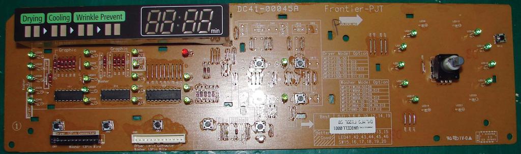
68 11-1
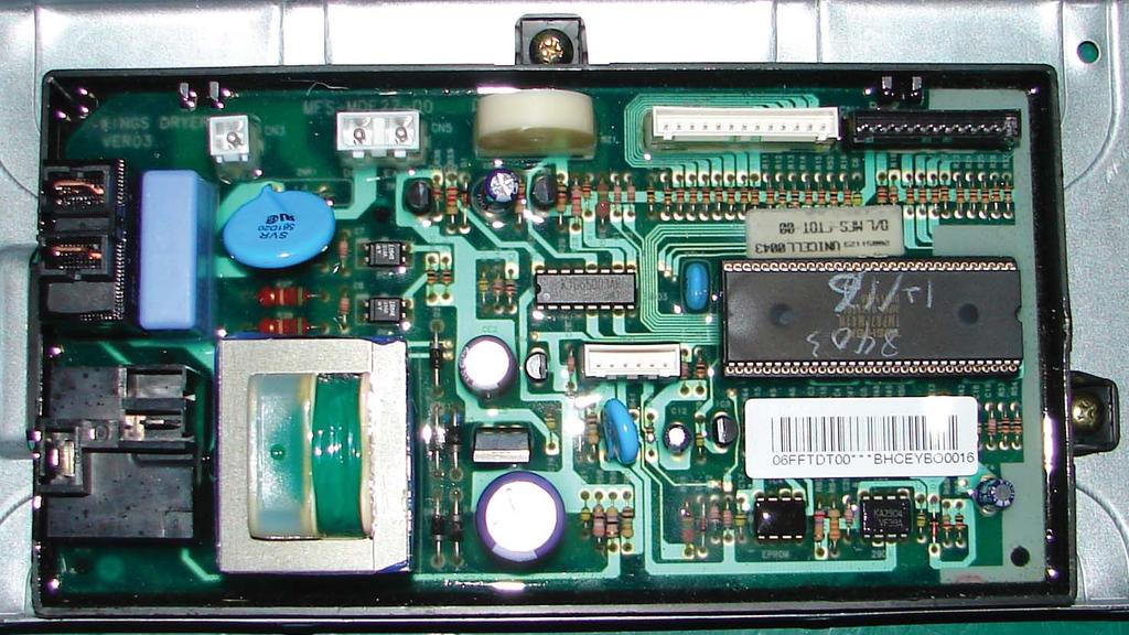
69 11-2
70 12. SCHEMATIC DIAGRAMS * This Document can not be used without Samsung s authorization. 12-1
71 * This Document can not be used without Samsung s authorization. 12-2
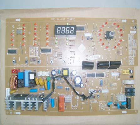
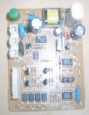
72 13-1
Gas and Electric Dryer user manual
 DV48H7400E(G)* DV45H7400E(G)* DV45H7200E(G)* DV45H7000E(G)* Gas and Electric Dryer user manual This manual is made with 100% recycled paper. imagine the possibilities Thank you for purchasing this Samsung
Dryer. User manual DV22K6800** DV22K A-00_EN (US)_ indd :15:41
_ indd :15:41") Dryer User manual DV22K6800** DV22K6800-03650A-00_EN (US)_151211.indd 1 2015-12-11 7:15:41 Before installation Read through the following instructions before installing the dryer, and keep this manual
Dryer User manual DV22K6800** DV22K6800-03650A-00_EN (US)_151211.indd 1 2015-12-11 7:15:41 Before installation Read through the following instructions before installing the dryer, and keep this manual
AUTOMATIC DRYER INSTALLATION INSTRUCTIONS MISE EN SERVICE SÉCHEUSE AUTOMATIQUE INSTRUCCIONES DE INSTALACIÓN DE LA SECADORA AUTOMÁTICA
 AUTOMATIC DRYER INSTALLATION INSTRUCTIONS MISE EN SERVICE SÉCHEUSE AUTOMATIQUE INSTRUCCIONES DE INSTALACIÓN DE LA SECADORA AUTOMÁTICA The installation, including a proper exhaust system, is the responsibility
AUTOMATIC DRYER INSTALLATION INSTRUCTIONS
 AUTOMATIC DRYER INSTALLATION INSTRUCTIONS The installation, including a proper exhaust system, is the responsibility of the owner. LEAVE THESE INSTRUCTIONS WITH THE OWNER Printed in U.S.A. 6 37699 Read
Installation Instructions
 Installation Instructions Gas & Electric Dryer Before beginning installation, carefully read these instructions. This will simplify the installation and ensure the dryer is installed correctly and safely.
Questions? Call 800.GE.CARES ( ) or visit our Web site at: GEAppliances.com In Canada, call or visit
 or visit our Web site at: GEAppliances.com In Canada, call or visit") Installation Instructions Electric Dryer 01 Questions? Call 800.GE.CARES (800.432.2737) or visit our Web site at: GEAppliances.com In Canada, call 1.800.561.3344 or visit www.geappliances.ca BEFORE YOU
Installation Instructions Electric Dryer 01 Questions? Call 800.GE.CARES (800.432.2737) or visit our Web site at: GEAppliances.com In Canada, call 1.800.561.3344 or visit www.geappliances.ca BEFORE YOU
Installation Electric Dryers Instructions 01
 Installation Electric Dryers Instructions 01 Questions? Call 800.GE.CARES (800.432.2737) or visit our Web site at: GEAppliances.com This is the safety alert symbol. This symbol alerts you to potential
SAFE DRINKING WATER AND TOXIC ENFORCEMENT ACT
 Installation instructions for your new Spacemaker Laundry WSM2780 Gas Before you begin Read these instructions completely and carefully. IMPORTANT OBSERVE ALL GOVERNING CODES AND ORDINANCES. Note to Installer
Gas and Electric Dryer
 DV42H5400* DV42H5200* DV42H5000* Gas and Electric Dryer User manual Imagine the possibilities Thank you for purchasing this Samsung product. To receive more complete service or accessory parts, please
Questions on Installation? Call: GECARES (US) or Visit our Web site at: (US) 4" DUCT CLAMPS (2) OR 4" SPRING CLAMPS (2)
 or Visit our Web site at: (US) 4 DUCT CLAMPS (2) OR 4 SPRING CLAMPS (2)") Installation Instructions Questions on Installation? Call: 1-800-GECARES (US) or Visit our Web site at: www.geappliances.com (US) Electric Dryer 49 37 BEFORE YOU BEGIN Read these instructions completely
Installation Instructions Questions on Installation? Call: 1-800-GECARES (US) or Visit our Web site at: www.geappliances.com (US) Electric Dryer 49 37 BEFORE YOU BEGIN Read these instructions completely
Installation Instructions
 Installation Instructions for Dryers Inside... Dimensions... Before You Start... 4 Installing the Dryer... 5 Installer Checklist... Back Cover Date Purchased Model Number Serial Number Keep these instructions
Questions? Call 800.GE.CARES ( ) or visit our Web site at: GEAppliances.com In Canada, call or visit
 or visit our Web site at: GEAppliances.com In Canada, call or visit") Installation Instructions Electric Dryer 01 Questions? Call 800.GE.CARES (800.432.2737) or visit our Web site at: GEAppliances.com In Canada, call 1.800.561.3344 or visit www.geappliances.ca BEFORE YOU
Installation Instructions Electric Dryer 01 Questions? Call 800.GE.CARES (800.432.2737) or visit our Web site at: GEAppliances.com In Canada, call 1.800.561.3344 or visit www.geappliances.ca BEFORE YOU
Installation Instructions
 Installation Instructions Before you begin... 2 Location... 2 Recommended grounding instructions... 2 Electrical requirements... 2 Exhaust requirements... 3 Water supply and drain requirements... 3 Please
29 IN. (73.7 CM) ELECTRIC DRYER INSTALLATION INSTRUCTIONS DRYER SAFETY
 ELECTRIC DRYER INSTALLATION INSTRUCTIONS DRYER SAFETY") 9 IN. (7.7 CM) ELECTRIC DRYER INSTALLATION INSTRUCTIONS DRYER SAFETY... INSTALLATION INSTRUCTIONS... Tools and Parts... Location Requirements... Electrical Requirements... Electrical Connection...4 Venting
9 IN. (7.7 CM) ELECTRIC DRYER INSTALLATION INSTRUCTIONS DRYER SAFETY... INSTALLATION INSTRUCTIONS... Tools and Parts... Location Requirements... Electrical Requirements... Electrical Connection...4 Venting
Gas and Electric Dryer user manual
 DV520AE* DV520AG* Gas and Electric Dryer user manual imagine the possibilities Thank you for purchasing this Samsung product. To receive more complete service, please register your product at www.samsung.com/register
DRYER INSTALLATION INSTRUCTIONS
 DRYER INSTALLATION INSTRUCTIONS Table of Contents DRYER SAFETY... 1 INSTALLATION REQUIREMENTS... 2 Tools and Parts... 2 Location Requirements... 3 Electrical Requirements... 5 INSTALLATION INSTRUCTIONS...
Gas and Electric Dryer user manual
 DV48H7400E(G)* DV45H7400E(G)* DV45H7200E(G)* DV45H7000E(G)* Gas and Electric Dryer user manual This manual is made with 100% recycled paper. imagine the possibilities Thank you for purchasing this Samsung
Installation Instructions
 Instructions for Dryers Original Instructions Keep These Instructions for Future Reference. CAUTION: Read the instructions before using the machine. (If this machine changes ownership, this manual must
Please read the following installation instructions first after purchasing this product or transporting it to another location.
 0 INSTALLATION INSTALLATION Installation Overview Please read the following installation instructions first after purchasing this product or transporting it to another location. Check and choose the proper
Installation Instructions
 Instructions for Stacked Dryers Original Instructions Keep These Instructions for Future Reference. (If this machine changes ownership, this manual must accompany machine.) www.speedqueen.com Part No.
Installation Instructions T 9822 Gas Dryer. en - US, CA. To prevent accidents
 Installation Instructions T 9822 Gas Dryer To prevent accidents en - US, CA and appliance damage read these instructions before installation or use. M.-Nr. 07 431 110 2 WARNING For your safety the information
Service. Compact Dryer MDE2400AY*
 Service This manual is to be used by qualified appliance technicians only. Maytag does not assume any responsibility for property damage or personal injury for improper service procedures done by an unqualified
Gas and Electric Dryer user manual
 DV337 DV328 Gas and Electric Dryer user manual imagine the possibilities Thank you for purchasing a Samsung product. To receive a more complete service, please register your product at www.samsung.com/global/register
Installation Instructions
 Instructions for Dryers Original Instructions Keep These Instructions for Future Reference. (If this machine changes ownership, this manual must accompany machine.) www.speedqueen.com Part No. 5439R October
CLOTHES DRYER Technical Information
 CLOTHES DRYER Technical Information Due to possibility of personal injury or property damage, always contact an authorized technician for servicing or repair of this unit. Refer to Service Manual (DV456*,DV422*,DV400*)
Installation Instructions
 Instructions for Dryers Original Instructions Keep These Instructions for Future Reference. (If this machine changes ownership, this manual must accompany machine.) www.alliancelaundry.com Part No. D5486ENR
Automatic Dryers. Installation. Keep These Instructions for Future Reference. (If this machine changes ownership, this manual must accompany machine.
 Automatic Dryers Installation D715I Keep These Instructions for Future Reference. (If this machine changes ownership, this manual must accompany machine.) Part No. R4 June 2007 IMPORTANT: The electrical
Installation Instructions
 Instructions for Dryers Original Instructions Keep These Instructions for Future Reference. (If this machine changes ownership, this manual must accompany machine.) www.speedqueen.com Part No. D5439R2
NOTE: The gas service to the Dryer must conform with local codes and ordinances
 Frigidaire Pre-lnstallation Requirements... 2 Electrical Requirements... 2 Exhaust System Requirements... 3-4 Gas Supply Requirements... 4 Installation Instructions Location of Your Dryer... 4-5 Mobile
Dryer. User manual DVE(G)45M5500*
45M5500*") Dryer User manual DVE(G)45M5500* DV5500M_03381G_EN.indd 1 12/26/2016 11:01:56 AM Contents Contents Safety information 4 What you need to know about the safety instructions 4 Important safety symbols 4
Dryer User manual DVE(G)45M5500* DV5500M_03381G_EN.indd 1 12/26/2016 11:01:56 AM Contents Contents Safety information 4 What you need to know about the safety instructions 4 Important safety symbols 4
Installation Instructions
 Installation Instructions Full Size Laundry Center Gas & Electric Before beginning installation, carefully read these instructions. This will simplify the installation and ensure the laundry center is
Gas and Electric Dryer Owner s Manual
 Gas and Electric Dryer Owner s Manual Register your product at www.samsung.com/global/register Code No.: DC68-02312A-04_EN Features Extra Large Capacity Ultra washing and drying are at your fingertips!
Smart Choice Electric Dryer Installation Kit
 pn/ 5304501810 Smart Choice Electric Dryer Installation Kit BEFORE BEGINNING INSTALLATION, READ ALL MANUFACTURER S INSTALLATION INSTRUCTIONS THOROUGHLY DANGER FIRE AND ELECTROCUTION HAZARD YOU DO NOT POSSESS
Gas and Electric Dryer user manual
 DV338AEW DV338AGW Gas and Electric Dryer user manual imagine the possibilities Thank you for purchasing this Samsung product. To receive more complete service, please register your product at www.samsung.com/global/register
Installation Instructions
 Instructions for Dryers Original Instructions Keep These Instructions for Future Reference. (If this machine changes ownership, this manual must accompany machine.) www.speedqueen.com Part No. 54320R October
Gas and Electric Dryer user manual
 DV350AE* DV350AG* Gas and Electric Dryer user manual imagine the possibilities Thank you for purchasing this Samsung product. To receive more complete service, please register your product at www.samsung.com/register
Installation Instructions
 Installation Instructions IMPORTANT: Read and save these instructions. IMPORTANT: Installer: Leave Installation Instructions with the homeowner. Homeowner: Keep Installation Instructions for future reference.
Installation instructions for vented tumble dryer DOMESTIC. Dear Customer,
 Dear Customer, Read these instructions carefully and completely before you install the machine. The installation should be carried out by a qualified person who is familiar with all local codes and ordinances
CLOTHES DRYER Technical Information
 CLOTHES DRYER Technical Information IMPORTANT SAFETY NOTICE For Technicians only This service data sheet is intended for use by persons having electrical, electronic, and mechanical experience and knowledge
Installation Instructions
 Instructions for Dryers Original Instructions Keep These Instructions for Future Reference. CAUTION: Read the instructions before using the machine. (If this machine changes ownership, this manual must
INSTALLATION INSTRUCTIONS TD75. Vented tumble dryer DOMESTIC. Carefully read the instructions for use before using the dryer.
 INSTALLATION INSTRUCTIONS TD75 Vented tumble dryer DOMESTIC Carefully read the instructions for use before using the dryer. Dear Customer, Read these instructions carefully and completely before you install
Questions? Call 800.GE.CARES ( ) or visit our Web site at: GEAppliances.ca
 or visit our Web site at: GEAppliances.ca") Installation Instructions Dryers Questions? Call 800.GE.CARES (800.432.2737) or visit our Web site at: GEAppliances.ca This is the safety alert symbol. This symbol alerts you to potential hazards that
Installation Instructions Dryers Questions? Call 800.GE.CARES (800.432.2737) or visit our Web site at: GEAppliances.ca This is the safety alert symbol. This symbol alerts you to potential hazards that
Installation Instructions
 Instructions for Dryers Original Instructions Keep These Instructions for Future Reference. (If this machine changes ownership, this manual must accompany machine.) Part No. 514446ENR2 February 2015 Front
27 ELECTRIC & GAS DRYERS
 CONSUMER SERVICES TECHNICAL EDUCATION GROUP PRESENTS L-63 27 ELECTRIC & GAS DRYERS JOB AID Part No. 4322260 I INTRODUCTION This Job Aid, 27 ELECTRIC & GAS DRYERS, (Part No. 4322260), provides specific
Gas and Electric Dryer Owner s Manual
 Gas and Electric Dryer Owner s Manual Register your product at www.samsung.com/global/register Code No.: DC68-02312A-EN Safety Precautions Congratulations on your new Samsung Dryer. This manual contains
INSTALLATION INSTRUCTIONS ELECTRIC DRYER
 INSTALLATION INSTRUCTIONS ELECTRIC DRYER Table of Contents... 2 IMPORTANT: Save for local electrical inspector s use. 3397627C DRYER SAFETY... 2 INSTALLATION INSTRUCTIONS... 4 Tools and Parts... 4 Location
ELECTRIC DRYER INSTALLATION INSTRUCTIONS
 ELECTRIC DRYER INSTALLATION INSTRUCTIONS Para una version de estas instrucciones en español, visite www.whirlpool.com Table of Contents DRYER SAFETY... 2 Installation Requirements... 3 Tools and Parts...
Dryer. User manual DVE(G)52M8650*
52M8650*") Dryer User manual DVE(G)52M8650* DV8650M-03170X-00_EN.indd 1 2017-01-06 4:36:49 Contents Contents Safety information 4 What you need to know about the safety instructions 4 Important safety symbols 4 Important
Dryer User manual DVE(G)52M8650* DV8650M-03170X-00_EN.indd 1 2017-01-06 4:36:49 Contents Contents Safety information 4 What you need to know about the safety instructions 4 Important safety symbols 4 Important
Questions? Call 800.GE.CARES ( ) or visit our Web site at: GEAppliances.com
 or visit our Web site at: GEAppliances.com") Installation Gas Dryers Instructions 02 DESIGN CERTIFIED Questions? Call 800.GE.CARES (800.432.2737) or visit our Web site at: GEAppliances.com This is the safety alert symbol. This symbol alerts you to
Installation Gas Dryers Instructions 02 DESIGN CERTIFIED Questions? Call 800.GE.CARES (800.432.2737) or visit our Web site at: GEAppliances.com This is the safety alert symbol. This symbol alerts you to
ELECTRIC DRYER INSTALLATION INSTRUCTIONS
 ELECTRIC DRYER INSTALLATION INSTRUCTIONS Table of Contents DRYER SAFETY... 2 INSTALLATION REQUIREMENTS... 3 Tools and Parts... 3 LOCATION REQUIREMENTS... 4 ELECTRICAL REQUIREMENTS... 6 INSTALL LEVELING
DANGER Indicates a hazardous situation which, if not avoided, will result in death or serious injury.
 Installation Gas Dryers Instructions 02 DESIGN CERTIFIED Questions? Call 800.561.3344 or visit our Web site at: GEAppliances.ca This is the safety alert symbol. This symbol alerts you to potential hazards
Installation Instructions
 Instructions for Dryers Original Instructions Keep These Instructions for Future Reference. (If this machine changes ownership, this manual must accompany machine.) www.alliancelaundry.com Part No. 514685R1
Service. 27 Dryer MDE9700A* MDG9700A*
 Service This manual is to be used by qualified appliance technicians only. Maytag does not assume any responsibility for property damage or personal injury for improper service procedures done by an unqualified
INSTALLATION INSTRUCTIONS INSTRUCTIONS D INSTALLATION INSTRUCCIONES DE INSTALACIÓN
 EN FRONT LOAD DRYER FR SÉCHEUSE Á CHARGEMENT FRONTAL ES SECADORA DE CARGA FRONTAL INSTALLATION INSTRUCTIONS INSTRUCTIONS D INSTALLATION INSTRUCCIONES DE INSTALACIÓN 2 IMPORTANT SAFETY INSTRUCTIONS For
Dryer. User manual DVE(G)50M7450*
50M7450*") Dryer User manual DVE(G)50M7450* DV7450M-03170Z-00_EN.indd 1 2017-01-25 11:24:16 Contents Contents Safety information 4 What you need to know about the safety instructions 4 Important safety symbols 4
Dryer User manual DVE(G)50M7450* DV7450M-03170Z-00_EN.indd 1 2017-01-25 11:24:16 Contents Contents Safety information 4 What you need to know about the safety instructions 4 Important safety symbols 4
liance for Front Control Dryers Inside... Laundry Systems
 Installation Instructions for Front Control Dryers Inside Dimensions Before You Start 4 Installing the Dryer 5 Installer Checklist Back Cover Date Purchased Model Number Serial Number Keep these instructions
ELECTRIC DRYER INSTALLATION INSTRUCTIONS
 ELECTRIC DRYER INSTALLATION INSTRUCTIONS Table of Contents DRYER SAFETY... 2 INSTALLATION REQUIREMENTS... 3 Tools and Parts... 3 LOCATION REQUIREMENTS... 4 ELECTRICAL REQUIREMENTS... 5 INSTALL LEVELING
Stacked Clothes Dryer Nonmetered and Metered
 Stacked Clothes Dryer Nonmetered and Metered Electric and Gas Models Installation/Operation Para bajar una copia de estas instrucciones en español, visite www.comlaundry.com. D009C Keep These Instructions
Installation Instructions
 Have questions about your dryer? Check your Use and Care Guide for a toll-free number to call, or call your dealer. The dealer is listed in the Yellow Pages of your phone directory under Appliances Household
COMMERCIAL GAS AND ELECTRIC STACKED WASHER/ DRYER INSTALLATION INSTRUCTIONS
 COMMERCIAL GAS AND ELECTRIC STACKED WASHER/ DRYER INSTALLATION INSTRUCTIONS MODELS MLG19PD, MLE19PD The installation, including a proper exhaust system, is the responsibility of the owner. LEAVE THESE
An occurrence of an Error will make a sound of error melody for 5sec and continuously show one of the Error Displays from the following errors.
 4. Troubleshooting 4-1. Error items and diagnostic codes An occurrence of an Error will make a sound of error melody for 5sec and continuously show one of the Error Displays from the following errors.
Installation instructions for the T 9820 Gas Dryer
 Installation instructions for the T 9820 Gas Dryer The T 9820 gas dryer is only approved for use in the USA and Canada. It is not approved for use in Mexico. To prevent accidents en - US, CA and machine
Clothes Dryer Electric and Gas Models
 Clothes Dryer Electric and Gas Models Installation/Operation DRY684C Para bajar una copia de estas instrucciones en español, visite www.comlaundry.com. Keep These Instructions for Future Reference. (If
ELECTRIC COOKTOP INSTALLATION INSTRUCTIONS
 INSTALLATION AND SERVICE MUST BE PERFORMED BY A QUALIFIED INSTALLER. IMPORTANT: SAVE FOR LOCAL ELECTRICAL INSPECTOR'S USE. READ AND SAVE THESE INSTRUCTIONS FOR FUTURE REFERENCE. U.S.A. WARNING FOR YOUR
INSTALLATION INSTRUCTIONS FOR FREESTANDING DUAL FUEL
 INSTALLATION AND SERVICE MUST BE PERFORMED BY A QUALIFIED INSTALLER. IMPORTANT: SAVE FOR LOCAL ELECTRICAL INSPECTOR'S USE. READ AND SAVE THESE INSTRUCTIONS FOR FUTURE REFERENCE. If the information in this
Clothes Dryer Nonmetered and Metered
 Clothes Dryer Nonmetered and Metered Electric and Gas Models Installation/Operation D677I Keep These Instructions for Future Reference. (If this machine changes ownership, this manual must accompany machine.)
Installation Instructions
 Instructions for Dryers Original Instructions Keep These Instructions for Future Reference. CAUTION: Read the instructions before using the machine. (If this machine changes ownership, this manual must
INSTALLATION INSTRUCTIONS INSTRUCTIONS D INSTALLATION INSTRUCCIONES DE INSTALACIÓN
 EN FRONT LOAD DRYER FR SÉCHEUSE Á CHARGEMENT FRONTAL ES SECADORA DE CARGA FRONTAL INSTALLATION INSTRUCTIONS INSTRUCTIONS D INSTALLATION INSTRUCCIONES DE INSTALACIÓN A07020301B January 2017 2 Important
Electric Dryer Installation Instructions
 Electric Dryer Installation Instructions Table of Contents DRYER SAFETY...2 Installation Requirements...3 Tools and Parts... 3 Location Requirements... 3 Electrical Requirements... 4 Install Leveling Legs...
Gas and Electric Dryer
 DV455-02836F-02_EN_20120625.indd 1 2012-06-25 5:20:16 DV455* Gas and Electric Dryer user manual This manual is made with 100% recycled paper. imagine the possibilities Thank you for purchasing this Samsung
Clothes Dryer. Installation/Operation. Electric and Gas Models
 Clothes Dryer Electric and Gas Models Installation/Operation Original Instructions Keep These Instructions for Future Reference. CAUTION: Read the instructions before using the machine. (If this machine
GAS COOKTOP INSTALLATION INSTRUCTIONS
 INSTALLATION AND SERVICE MUST BE PERFORMED BY A QUALIFIED INSTALLER. IMPORTANT: SAVE FOR LOCAL ELECTRICAL INSPECTOR'S USE. READ AND SAVE THESE INSTRUCTIONS FOR FUTURE REFERENCE. WARNING If the information
GAS COOKTOP INSTALLATION INSTRUCTIONS
 INSTALLATION AND SERVICE MUST BE PERFORMED BY A QUALIFIED INSTALLER. IMPORTANT: SAVE FOR LOCAL ELECTRICAL INSPECTOR'S USE. READ AND SAVE THESE INSTRUCTIONS FOR FUTURE REFERENCE. WARNING If the information
Safety Instructions 2-5 Installation Instructions 6-21 Operating Instructions 22-38
 www.geappliances.ca Dryers Safety Instructions 2-5 Installation Instructions 6-21 Electric Dryer 6-12 Gas Dryer 13-20 Rough-In Dimensions 21 Operating Instructions 22-38 Control Panels 22-24 Cycle Options
Electric Dryer Installation Instructions
 Electric Dryer Installation Instructions Table of Contents DRYER SAFETY... 2 INSTALLATION REQUIREMENTS... 3 Tools and Parts... 3 Location Requirements... 4 Electrical Requirements... 6 Install Leveling
Clothes Dryer. Installation/Operation. Electric and Gas Models
 Clothes Dryer Electric and Gas Models Installation/Operation Original Instructions Keep These Instructions for Future Reference. CAUTION: Read the instructions before using the machine. (If this machine
Clothes Dryer. Installation/Operation. Nonmetered and Metered. Electric and Gas Models
 Clothes Dryer Nonmetered and Metered Electric and Gas Models Installation/Operation D677I Keep These Instructions for Future Reference. (If this machine changes ownership, this manual must accompany machine.)
Clothes Dryer. Keep These Instructions for Future Reference. (If this machine changes ownership, this manual must accompany machine.
 Clothes Dryer Nonmetered and Metered Electric and Gas Models Installation/Operation D677I Keep These Instructions for Future Reference. (If this machine changes ownership, this manual must accompany machine.)
Questions on Installation? Call: 800.GE.CARES (US) WARNING RISK OF FIRE TOOLS YOU WILL NEED 4" DIA. METAL DUCT (RECOMMENDED)
 WARNING RISK OF FIRE TOOLS YOU WILL NEED 4 DIA. METAL DUCT (RECOMMENDED)") Installation Instructions Electric Dryer 04 Questions on Installation? Call: 800.GE.CARES (US) www.geappliances.com (US) BEFORE YOU BEGIN Read these instructions completely and carefully. IMPORTANT- IMPORTANT-
Installation Instructions Electric Dryer 04 Questions on Installation? Call: 800.GE.CARES (US) www.geappliances.com (US) BEFORE YOU BEGIN Read these instructions completely and carefully. IMPORTANT- IMPORTANT-
Installation. All about the. of your Dryer TABLE OF CONTENTS
 All about the Installation of your Dryer TABLE OF CONTENTS Important Safety Instructions... 2-3 Accessories... 24 Installation Requirements... 4-11 Français... 25 Installation Instructions...12-19 Español...
! WARNING To avoid risk of electrical shock, personal injury or death; disconnect power before servicing, unless testing requires power.
 27 Electric Dryer Technical Information MDE9700A * Due to possibility of personal injury or property damage, always contact an authorized technician for servicing or repair of this unit. Refer to Service
AeroCare clothes dryer. Installation instructions. and User guide
 AeroCare clothes dryer Installation instructions and User guide US WARNING! For your safety the information in this manual must be followed to minimize the risk of fire or explosion or to prevent property
Installation Instructions
 Have questions about your dryer? Check your Use and Care Guide for a toll-free number to call, or call your dealer. The dealer is listed in the Yellow Pages of your phone directory under Appliances Household
! WARNING To avoid risk of electrical shock, personal injury or death; disconnect power before servicing, unless testing requires power.
 27 Gas Dryer Technical Information MDG9700A * Due to possibility of personal injury or property damage, always contact an authorized technician for servicing or repair of this unit. Refer to Service Manual
DISHWASHER. Models DW2432 and DW2432SS. Installation Manual. Write Serial Number (on inner door of unit) here:
 here:") DISHWASHER Models DW2432 and DW2432SS Installation Manual Write Serial Number (on inner door of unit) here: Felix Storch, Inc. Summit Appliance Division 770 Garrison Avenue Bronx, New York 10474 www.summitappliance.com
DISHWASHER Models DW2432 and DW2432SS Installation Manual Write Serial Number (on inner door of unit) here: Felix Storch, Inc. Summit Appliance Division 770 Garrison Avenue Bronx, New York 10474 www.summitappliance.com
Installation. Instructions. Gas Dryer. Questions? See Owner's Manual or call Amana Consumer Affairs Department DRYER DRUM
 BULT BETTER THAN T HAS TO Br nstallation nstructions Gas Dryer Keep instructions for future reference. Be sure manual stays with dryer. Questions? See Owner's Manual or call Amana Consumer Affairs Department
Kenmore Steam Dryer. Secador con vapor. Use & Care Guide Manual de Uso y Cuidado. Models/Modelos: *, *
 Use & Care Guide Manual de Uso y Cuidado Models/Modelos: 796.8139*, 796.9139* Kenmore Steam Dryer Secador con vapor * = color number, número de color MFL67731087 Sears Brands Management Corporation Hoffman
ELECTRONIC ELECTRIC DRYER
 TM ELECTRONIC ELECTRIC DRYER Use & Care Guide For questions about features, operation/performance, parts accessories or service call: 1-800-253-1301 or visit our website at... www.whirlpool.com Table of
Clothes Dryer. Installation/Operation. Nonmetered and metered Electric and Gas Models
 Clothes Dryer Nonmetered and metered Electric and Gas Models Installation/Operation Original Instructions Keep These Instructions for Future Reference. CAUTION: Read the instructions before using the machine.
GAS COOKTOP INSTALLATION INSTRUCTIONS BEFORE YOU BEGIN. IMPORTANT Save these instructions for local electrical inspector s use.
 GAS COOKTOP INSTALLATION INSTRUCTIONS Please read this guide thoroughly before installation. To contact LG Electronics, 24 hours a day, 7 days a week: 1-800-243-0000 (U.S.A.) 1-888-542-2623 (Canada) Or
Fast Track Troubleshooting
 Fast Track Troubleshooting Models: DV5471AE DV5471AG NOTICE: All Dryers Parts Change 6/2010: Motor Pulley, page 5; Blower Housing, page 4 IMPORTANT SAFETY NOTICE For Technicians Only This service data
Use & Care Guide MD6400. Table of Contents Important Safety Instructions Special Laundry Tips Dryer Exhaust Tips... 8
 MD6400 Table of Contents Important Safety Instructions..............1-2 Using the Controls......... 3-4 Select Temperature Select Signal Select Cycle Pull the Control Dial out to Start Operating Tips...............
Questions on Installation? Call: 800.GE.CARES (US) WARNING RISK OF FIRE 4" DIA. METAL DUCT (RECOMMENDED) 4" DUCT CLAMPS (2) OR 4" SPRING CLAMPS (2)
 WARNING RISK OF FIRE 4 DIA. METAL DUCT (RECOMMENDED) 4 DUCT CLAMPS (2) OR 4 SPRING CLAMPS (2)") Installation Instructions Electric Dryer 01 Questions on Installation? Call: 800.GE.CARES (US) www.geappliances.com (US) PEDESTALS FOR DRYERS (comes with individual installation instructions) Three models
Installation Instructions Electric Dryer 01 Questions on Installation? Call: 800.GE.CARES (US) www.geappliances.com (US) PEDESTALS FOR DRYERS (comes with individual installation instructions) Three models
Stacked Washer and Dryer Electric and Gas Models
 Stacked Washer and Dryer Electric and Gas Models Installation/Operation SWD54C Keep These Instructions for Future Reference. (If this machine changes ownership, this manual must accompany machine.) www.comlaundry.com
SERVICE MANUAL ELECTRIC & GAS DRYER MODEL : DLE5911W DLE2511W DLE5932W DLE5932S DLE2532W DLE0332W
 Website:http://www.LGservice.com [For U.S.A] www.lg.ca [For Canada] ELECTRIC & GAS DRYER SERVICE MANUAL CAUTION READ THIS MANUAL CAREFULLY TO DIAGSE TROUBLES CORRECTLY BEFORE OFFERING SERVICE. MODEL :
Operating Instructions Tumble Dryer
 Operating Instructions Tumble Dryer Save these instructions for future reference Dear Customer, Thank you for choosing this quality product from ASKO. We hope it will meet all of your expectations and
Installation Instructions
 Instructions for Stacked Washer/Dryers Original Instructions Keep These Instructions for Future Reference. (If this machine changes ownership, this manual must accompany machine.) www.speedqueen.com Part
Dryer. User manual DV22K6800**
 Dryer User manual DV22K6800** DV22K6800-03650A-01_EN.indd 1 2016-09-26 5:28:58 Contents Contents Safety information 4 What you need to know about the safety instructions 4 Important safety symbols 4 Important
24 IN. (61 CM) ELECTRIC WASHER/DRYER INSTALLATION INSTRUCTIONS WASHER/DRYER SAFETY DANGER WARNING
 ELECTRIC WASHER/DRYER INSTALLATION INSTRUCTIONS WASHER/DRYER SAFETY DANGER WARNING") 4 IN. (6 CM) ELECTRIC WASHER/DRYER INSTALLATION INSTRUCTIONS WASHER/DRYER SAFETY... INSTALLATION INSTRUCTIONS... Tools and Parts... Alternate Parts... Location Requirements... Drain System... Electrical
4 IN. (6 CM) ELECTRIC WASHER/DRYER INSTALLATION INSTRUCTIONS WASHER/DRYER SAFETY... INSTALLATION INSTRUCTIONS... Tools and Parts... Alternate Parts... Location Requirements... Drain System... Electrical
Installation Instructions
 Instructions for Stacked Washer/Dryers Original Instructions Keep These Instructions for Future Reference. CAUTION: Read the instructions before using the machine. (If this machine changes ownership, this