Instructions for installtion and use English
|
|
|
- Russell Taylor
- 6 years ago
- Views:
Transcription

1 FR Instructions for installtion and use English EN More languages on: H A - WBU /10
2 Read this manual carefully before installing, maintaining or repairing this device! The symbol indicates important information that must be taken into account in order to avoid risk of personal injury and/or damage to the appliance. The symbol indicates useful information. Warnings Our products may be subject to change without notice as part of our continuous improvement policy. Exclusive use: for dehumidifying swimming pool premises (must not be used for any other purpose), This device must be installed and serviced by certified professionals approved in the electrical, hydraulic and cooling domains, It must be installed in premises that are closed and well aired; in an area that is: not exposed to freezing risk, out of reach of water splashes, and where no pool maintenance products are stored, the installation in outside involves the suppression of the guarantee, The device must be installed by a qualified technician according to the manufacturer s instructions and in compliance with local regulations. The installer is responsible for the correct installation of the device and for ensuring compliance with local regulations. The manufacturer shall not be held liable for any potential issues that may occur as a result of failure to comply with local standards pertaining to installation, Incorrect installation may cause serious damage and/or personal injuries (possibly death), This appliance must be handled by competent and qualified personnel (physically and mentally) who are familiar with the operating instructions (by reading the user guide). Persons who do not satisfy these requirements must not handle the device so as to avoid exposure to potentially dangerous parts. If the device malfunctions: do not attempt to repair the device yourself, call your retailer, Before carrying out any operation on the machine, check that the power supply is cut and that the machine is tagged out, Prior to any operation, check that the voltage on the identification plate of the appliance corresponds to the main voltage available on site, The warranty will automatically become void if any safety device is removed or shunted. This will also apply if any parts are replaced with parts purchased anywhere else than from our stores, Keep the appliance out of the reach of children, Do not discharge R407C fluid into the atmosphere: R407C is a fluorinated greenhouse effect gas, covered by the Kyoto Protocol, with a Global Warming Potential (GWP) = 1653 (Directive EC 842/2006). According to French decree no of 7th May 2007, if the appliance has more than 2 kg of refrigerant gas (refer to manufacturer specifications), the cooling circuit must be checked for leakage at least once a year. This operation must be carried out by a certified cooling appliance specialist H A1.EN 2012/10 1

3 Summary 1. Information before installation General terms of delivery, storage and transport Content Operating conditions Technical specifications Installation Installation requirements Access to technical compartment Connection to surrounding air Inset connection Connection of the condensation drainage Electric connections Connecting the options Operation Starting the appliance Checks Adjusting the duct network Options starting up Maintenance Maintenance instructions Additional recommendations Spare parts Recycling the product Resolution of problem Status and faults in the ECP 600 settings FAQ Product registration Conformity certificate Available in the appendices at the end of the manual: - wiring diagrams - Dimensions 1. Information before installation 1.1 General terms of delivery, storage and transport Any equipment, even carriage and packing free, travels at the consignee's risk. The consignee shall make reservations in writing on the carrier's bill of lading if damage is detected, caused during transport (confirmation to be sent to the carrier within 48 hours by registered mail with acknowledgement of receipt). The device must be transported and stored upright on its pallet in its original packaging. If the device has been turned on its side, mention your reservations in writing to the carrier. 1.2 Content Sirocco inset(x1) sleeve (x2) + frame with cadre suction grid and filter (x1) + frame with blowing grid (x1) + frame fixture kit (x1) Hygro Control (x1) antivibration studs (x4) dowel (x2) long bolt (x2) H A1.EN 2012/10 2
 optimum operating conditions: between 25 C and 30 C Hygro Control on request 1.")
4 Sirocco ambient (x1) Hygro Control (x1) anti vibration studs (x4) dowel (x2) long bolt (x2) 1.3 Operating conditions operating range: 10 C to 40 C (temperature in the swimming pool hall) optimum operating conditions: between 25 C and 30 C Hygro Control on request 1.4 Technical specifications Appliance Dehumidifying Power restored on the Power consumed * capacity * ambient air* Air flow rate Without option L/h W W m³/h Sirocco L/h 990 W 2080 W 600 m 3 /h Sirocco L/h 1100 W 2310 W 800 m 3 /h Sirocco L/h 1340 W 2810 W 1000 m 3 /h * with ambient air at +30 C and relative humidity of 70% unit protection class: Sirocco ambient: IP 44 ; Sirocco inset: IP 45 class: I refrigerant gas: R407C refrigerant charge: see product information plate 2. Installation 2.1 Installation requirements Install the appliance on a level base, to avoid any overflows from the condensation tray (adjustment by two hexagonal screws, see 2.2), Easy access to the appliance for maintenance and connections, Place nothing in front of or on the blowing and suction grates, anti vibration studs (supplied) must be installed under the base when the appliance is placed on the floor or on a support, For a swimming pool building with a high ceiling or visible roof frame: destratification of the upper layers of the room = one or several fans with PVC blades or an air extractor with fresh air intake. Warning! 230 V AC appliances = must be outside volume 1 (see 2.1), Risk of stratification: - height of the room < 4 to 5 meters: mechanical ventilator unit or extractor, - height of the room > 5 to 8 meters: ceiling fans with large blades. Building requirements: swimming pool building = very damp room, During building make sure that: - the materials used are compatible with a swimming pool environment, - the walls are sufficiently waterproofed and insulated to avoid condensation forming in the room when relative humidity reaches 60 to 70%, Light structure buildings (verandas, shelters...): there is no risk of deterioration of the structure, even in case of dew as they are designed to support this (even with a relative humidity of 70%), Ventilation, renewal of air: - private pools: highly recommended, - public pools: compulsory. The air can be renewed by: - a simple mechanical ventilation unit, - a wall or roof extractor with fresh air intakes, This ventilation ensures the hygienic renewal of air, the removal of any chloramines present in the air, and the elimination of excessively hot air, whilst contributing to the dehumidification of the room. H A1.EN 2012/10 3
5 Following French norm NFC , the appliance should be installed: - Outside of area 1 (more than 2 metres from the edge of the pool) provided it is out of reach of potential splashes and protected by a dedicated 30 ma fuse, - Outside of area 2 (more than 3.5 metres from the edge of the pool) if the above conditions are not satisfied. 2.2 Access to technical compartment Adjusting screw to level the appliance or on each side 2.3 Connection to surrounding air Appliance on the ground (or on a support) Appliance fixed to the wall Pool * minimum distance ** maximum distance Sirocco suction grid blowing grid Hygro Control condensation drainage air renewal system (see 2.1) fresh air intake Using the two anchoring points at the back of the appliance (with two bolt screws, washers and plugs (supplied) in a solid wall ). Pool H A1.EN 2012/10 4
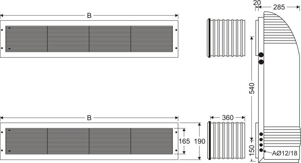
6 2.4 Inset connection Install the appliance in a technical room that is protected from freezing. the sleeves are: - to be incorporated in the wall at the time of construction, The blocks of polystyrene must remain in the sleeves to protect them from crushing. - or for sliding into the previously made reservations in the wall, Sirocco 55 Sirocco 80 Sirocco 110 Reserve dimensions (+2 mm / 0 mm) mm 618 x x x 165 plan for a gasket between the wall and the outside surface of each sleeve of the technical room and swimming pool room side, present the base of the appliance (without the cover) to the wall, opposite the sleeves and mark the two inside anchoring points, At this moment, the frames fixed to the back of the appliance must easily slot into each sleeve. install the fixing plugs into the solid wall using the marks, present the appliance again and from the inside screw in the bolt screws + washers into each plug, plan for an earth for the blowing and suction grid frame, following the electrical standards in force in the country. Technical room Swimming pool hall * minimum distance ** maximum distance Sirocco suction grid blowing grid Hygro Control condensation drainage air renewal system (see 2.1) fresh air intake Pool 2.5 Connection of the condensation drainage Plan for an adequate slope to ensure a good flow. Drainage shall be via a siphon or a funnel (condensation drainage pipe Ø12/18). Outlet provided for at the left of the appliance (condition ex works), with possibility of moving it to the right. Make sure the siphon is filled with water in such a way as not to create air suction by the condensation drainage pipe. For placing the condensation drainage: see mark A Ø12/18 dimensions in the appendix. 2.6 Electric connections Access to the electric box On each side H A1.EN 2012/10 5
, Electric cables must be fixed, 2.6.")
7 2.6.2 Voltage and protection The electrical supply must be provided through a protection and circuit breaking device (not supplied) complying with the standards and regulations in force in the country where it is installed, Electrical protection: 30 ma ground fault circuit breaker. Acceptable voltage variation tolerance: ± 10% (during operation), Electric cables must be fixed, Connections Terminal Sirocco single phase 230V 1N 50Hz: Main supply (see 2.6.4) Regulation connection (see 2.6.5) Terminal Sirocco 110 three phase 400V 3N 50HZ: Circulator connection (C C) or control of heat source by contact NO (3 6) (see 2.7.1) Internal connection terminals (do not modify the connections) Loose terminals may cause the supply terminal board to overheat, and will void the warranty. The appliance must be earthed. Risk of electrical shock inside the device. Only a qualified and experienced technician must install the device cables. If the power cable is damaged it must be replaced by a qualified technician Cable sizes Supply cable size: for cables of a maximum length of 20 metres (calculation basis: 5A/mm²), this must be checked and adapted depending on installation conditions. Option Voltage Nominal power consumption Maximum power consumption Cable size Unit A A mm² Sirocco 55 without option or hot water battery 230V 50Hz 4,45 5,9 3 x 2,5 3G2,5 Single phase Extra heating 2 kw 230V 50Hz 13,2 14,6 3 x 4 3G4 Sirocco 80 without option or hot water battery 230V 50Hz 5, x 2,5 3G2,5 Single phase Extra heating 3 kw 230V 50Hz x 6 3G6 Sirocco 110 without option or hot water battery 230V 50Hz 6,35 9,8 3 x 2,5 3G2,5 Single phase Extra heating 4,5 kw 230V 50Hz 26 29,4 3 x 10 3G10 Sirocco 110 three phase Main supply (see 2.6.4) Regulation connection (see 2.6.5) Contact normally open control of heat source Main supply 230Vac 50Hz for circulator (used with hot water battery, see 2.7.1) without option or hot water battery 400V 50Hz 2,8 3,8 5 x 2,5 5G2,5 Extra heating 4,5 kw 400V 50Hz 9,3 10,3 5 x 2,5 5G2,5 H A1.EN 2012/10 6 or


8 2.6.5 Hygro Control connection Hygro Control = digital display hygro thermostat = display and setting of pool hall temperature* and humidity - for installation location: see 2.3 or 2.4 and refer to 2.1, - correctly influenced by the swimming pool room air, - connect to terminals on the electric box. General Sirocco terminals Cable 5 x 1 mm², maximum length: 30 meters values setting on/off Temperature* and humidity programming or hygrothermostat settings Mains supply 12Vac 50Hz between terminals 4 and 5, The numbering of the terminals must be respected, Do not put these cables into the same duct as other 230 V or 400 V to avoid any risk of interference of the signals, Obstruct the place where the cable emerges from the wall or seal it by using materials other than silicone and silicone based materials, in order to avoid any arrival of air exterior to the room through the duct or dividing wall. Technical specifications Admissible room temperature C 0 55 Admissible humidity level % 0 90 Voltage Vac 12 Maximum voltage Vac 24 Protection index IP 20 Dimensions: width / height / depth mm 120 x 70 x 28 Hysteresis Humidity % 4 temperature C 1 Display Requesting heating Degrees Celsius Requesting dehumidification Temperature display* Degrees fahrenheit Relative Humidity * Only if your appliance is fitted with the hot water battery option, or extra electric heating. Hygro Control display Hygro thermostat Hygrostat Thermostat On standby Active H A1.EN 2012/10 7
9 By default: display of the temperature and/or desired relative humidity. Display of the ambient temperature and/or humidity by pressing once, C and/or %RH blink. To exit, press, or wait 10 seconds. Starting up and stopping the appliance Press for 5 seconds. Locking/unlocking the keyboard To lock and unlock the keyboard: - Hygro Control must be active, - press and simultaneously for 3 seconds, - the message is displayed or is removed. Adjusting the reference values - Hygro Control must be active, - press for 3 seconds, the modifiable value blinks, - use or to set the value, - press to validate, - and then to exit. Value range minimum maximum Comfort setting Humidity 55% 70% 65% Temperature 5 C 32 C 28 C If the keyboard is not used for 30 seconds, the setting will be abandoned and the last (non validated) setting will not be taken into account. Test mode / Manual override To force the appliance to operate for 30 minutes, even if the pool hall conditions do not trigger the request: - Hygro Control must be active, - press on for 3 seconds, a value blinks, - press again for 10 seconds, - all the digits light, or and the appliance starts up. To quit this mode, press the button for 5 seconds. Parameter setting in hygro thermostat or hygrostat mode Hygro Control shipped with the setting for hygro thermostat mode for appliances with the heating option for hygrostat mode for devices without the heating option. This setting must be changed if a heating option is added or removed. - Hygro Control must be on standby, - press and for 3 seconds : (hygro thermostat mode), - press or to select the function: (hygrostat mode), (thermostat mode) - validate by pressing. H A1.EN 2012/10 8
10 2.7 Connecting the options Hot water battery Connections on Ø15 21, male fitting. Outlet must be obligatorily on the left seen from the front. Swimming pool hall Technical room Circulator main supply cable Sirocco ambient Sirocco inset heating source blowing suction Automatic purge Circulator Check valve or solendoid valve Shut off valve Power Water flow rate Water load loss Primary 90/70 C 45/40 C 90/70 C 45/40 C 90/70 C 45/40 C Unit kw m³/h mce Sirocco Sirocco Sirocco Power restituted to the air at 27 C, entering the hot water battery. Connection to the primary circuit: front any valve or pump. Water temperature input to the hot water battery: 45 C minimum, 90 C maximum. Maximum pressure water battery circuit: 3 bars. 3. Operation 3.1 Starting the appliance Power on the appliance (by switching on the general terminal board), Only for three phased Sirocco 110: when the dehumidifier is switched on, check the status of the phase controller (KA4): - None of the indicators are lit = no power supply, - Green and orange indicators are lit = normal operating conditions, - Only green indictor lit = power supply is ok but phase inversion issue or missing phase. Cut off the power supply and invert two phases directly on the appliance connection terminal board. If the orange indicator does not light up after the phase inversion, check for the presence of the three phases on the phase order controller KA4. This operation must be only be carried out by a qualified professional. The phase order controller protects the compressor. It s forbidden to invert phases: on the power contactor (KM2) on the compressor set the humidity and temperature on the Hygro Control so that it triggers dehumidifying, see When the ECP 600 regulator is switched on ventilation is active for 5 minutes. This also occurs if the appliance is powered on and the on/off switch of the Hygro Control delivered with the appliance is used. H A1.EN 2012/10 9
 identically on all the blower grates. 3.")
11 3.2 Checks In the Hygro Control comfort model (see 2.6.5) check that hot air is coming out of the blower grates, check that the appliance is draining condensation. 3.3 Adjusting the duct network Set the air flow by adjusting the grate dampers (recommended speed 1metre/second) identically on all the blower grates. 3.4 Options starting up The heating options are operational from 4 C surrounding air temperature Extra heating starting up Hygro Control and adjust the thermostat to between 26 and 28 C (maximum 30 C), in general choose an air temperature 1 to 2 C higher than the pool water temperature, if your pool has a cover (shutter or bubble sheet type, etc.), you can lower the room temperature when it is in place (by adjusting the thermostat to about 20 C) and raise the pool hall temperature before removing the cover. check that with the VI/VP switch on VI, and no dehumidification or defrosting cycles in progress: - the fan stops operating, after post ventilation of 3 minutes when the reference room temperature on the pool room thermostat is lowered, - in the event of abnormal overheating, the appliance shuts down the heating option automatically, by shutting off the heating elements and keeping the ventilation operational (for as long as a heating request is active). This safety device has two levels of triggering: 1) by THS safety thermostat if the T C is > 65 C (it is automatically reset), 2) if the temperature continues to increase, the second positive THSM safety thermostat puts the appliance into safety mode. => reset it manually (with power off), after having checked that the appliance air flow is correct (with the VI/VP switch on VP ), that the grates are not obstructed, that the filter is not clogged, and the fan is not defective Hot water battery Supply the battery with hot water at 45 C minimum from the heat source (boiler, heat pump, geothermal energy, solar heating), installation must be carried out by a qualified technician, using a circulator (not supplied) which will be powered by terminals C C on the electrical terminal board. Insulate the hot water battery hot water pipes between the heat source and the appliance (for the purpose of limiting calorie loss). connection to a ZPCE double circuit gas boiler: connect the terminals 3 6 of the terminal board, to terminals 3 6 of the boiler terminal board, Terminals 3 6 can also ensure a heat source control function (see 2.6.3). adjust the thermostat between to 26 and 28 C (maximum 30 C), in general set the air temperature 1 to 2 C higher than the pool water temperature, If your pool has a cover (shutter or bubble sheet type, etc.), you can lower the room temperature (by adjusting the thermostat to about 20 C) when it is in place and raise the pool hall temperature before removing the cover. a post ventilation runs for 3 minutes when the reference temperature is reduced on the thermostat located in the pool hall (with the VI/VP switch on VI, without any dehumidification or defrosting cycles in progress): check that the circulator stops. Warning low temperature: if the dehumidifier hot water battery is not supplied by a boiler, but by an aero thermal or a geothermal system, the heating circuit water will be at a maximum temperature of C. The power of the battery will then be considerably lower (3 to 4 times less) than the nominal power given for water at C. If the power of the battery is lower than the heating needs of the room, plan for additional heating by radiator, heated floor or fan convector. H A1.EN 2012/10 10


, any modification of the order of phases on the distribution network or on the existing electrical installation is detected.")
12 4. Maintenance 4.1 Maintenance instructions A general servicing of the appliance is recommended both when winterizing and when restarting in order to ensure the proper operation of your heat pump, to preserve its performance and to prevent potential failures. Servicing costs will be borne by the user. Appliance powered off and unplugged from power supply! The appliance must have filters fitted when operating Monthly checks check visually that the condensation is drained. check for clogging in the filter: wash the filter with warm soapy water, rinse it abundantly and dry it, replace it if necessary Annual checks check that the electric cable connections, contactors are correctly tightened, check that each command relay, power switch and electronic protection device is operational, On the three phase Sirocco 110, via the phase controller (KA4), any modification of the order of phases on the distribution network or on the existing electrical installation is detected. The appliance then goes into fault mode (Led A1 and A3 ON, and orange light OFF for KA4), refer on 3.1. check the adjustment and operation of the Hygro Control and the water condenser thermostat if necessary clean the dust inside it using a jet of air, clean the whole unit with a slightly damp cloth, check the cleanliness of the condensation drainage tray and tube, to improve the operation of the appliance, it is possible to make a visual check of the fouling of the batteries (evaporator / condenser and hot water) by removing the cover from the appliance (switched off). Depending on the condition, clean with a silk brush and a vacuum cleaner. 4.2 Additional recommendations in relation to the Pressure Equipment Directive (PED 97/23/CE) Installation and maintenance the unit may not be installed close to combustible materials, or the air duct inlet of an adjacent building. with some devices, it is essential to fit protection grids if the unit is installed in an area with uncontrolled access. during installation, troubleshooting and maintenance, pipes may not be used as steps: the pipe could break under the weight, spilling refrigerant and possibly causing serious burns. when servicing the appliance, the composition and state of heat carrying fluid must be checked, as well as the absence of any refrigerant. during the annual unit sealing test in accordance with applicable legislation, the high and low pressure switches must be checked to ensure that they are securely fastened to the coolant circuit and that they cutoff the electrical circuit when tripped. during maintenance work, ensure there are no traces of corrosion or oil around cooling components. before beginning work on the cooling circuit, stop the device and wait for a few minutes before fitting the temperature and pressure sensors. Some elements such as the compressor and piping may reach temperatures in excess of 100 C and high pressures with the consequent risk of severe scalding Troubleshooting all soldering work must be carried out by a someone qualified to do so. replacement pipes must always be made of copper in compliance with standard NF EN H A1.EN 2012/10 11
13 leak detection; pressure test: - never use oxygen or dry air, risk of fire or explosion, - use dry nitrogen or the mixture of nitrogen and refrigerant indicated on the information plate, - the test pressure for both the high and low pressure circuits must not exceed 20 bar and 15 bar in the case the device is equipped of the manometer option. the high pressure circuit pipes are made of copper and have a diameter equal to or greater than 1 5/8. A certificate as indicated in 2.1 in compliance with standard NF EN will be requested from the supplier and filed in installation technical documentation. technical data relative to the safety requirements of the various applicable directives must be indicated on the information plate. This data must be recorded in the installation instructions for the device which are included in the installation technical file: model, code, serial number, maximum and minimum OT, OP, year of manufacture, EC label, manufacturer s address, refrigerant and weight, electrical parameters, thermo dynamic and acoustic performances. 4.3 Spare parts Spare parts Item number Representation Hygro Control sensor WCE03431 Filter Sirocco 55 inset Sirocco 80 inset Sirocco 110 inset Sirocco 55 ambient Sirocco 80 ambient Sirocco 110 ambient 4.4 Recycling the product WSD01911 WSD01912 WSD01913 WSD01914 WSD01915 This symbol means that the equipment must not throw it into your household waste. It will be collected selectively so that it can be reused, recycled or recovered. Any substances it may contain which are potentially dangerous to the environment will be eliminated or neutralised. Enquire with your retailer for the conditions that apply to the recycling of your product. 5. Resolution of problem 5.1 Status and faults in the ECP 600 settings Terminals Description N L mains supply 230Vac 50Hz to the ECP600 regulator output from compressor supply 230 Vac 50Hz Vac 50Hz output (used with the water condenser option) and protected by the ECP600 fuse ventilator 230Vac 50Hz output output for circulator hot water battery option 230Vac 50Hz output alarm report 230Vac 50Hz output contact NO (without polarity) control of heat source hot water battery option Input control sensor type PTC (inlet or defrost) 4 5 power supply 12Vac 50Hz H A1.EN 2012/10 12
14 Terminals Description 7 input 6Vac 50Hz given by the hygrostat function (request active if 6Vac 50Hz between 7 and 4) 2 input 6Vac 50Hz given by the thermostat function (request active if 6Vac 50Hz between 2 and 4) input 12Vac 50Hz fan heat fault (shunted not active) (fault active if 0Vac 50Hz between 8 and 4, 8 LEDs A1 and A2 are ON) input 12Vac 50Hz faults BP and/or HP, and/or phase order (Sirocco three phase) (fault active if 9 0Vac 50Hz between 9 and 4, LEDs A1 and A3 are ON) input 12Vac 50Hz compressor heat fault (shunted not active) (fault active if 0Vac 50Hz between and 4, LEDs A1 and B1 are ON) Hygro Thermostat Not used LCD A B Sh 4 5 intermittent ventilation (standard setting) or permanent ventilation (to permanently circulate the pool hall air) The ventilation is active when: - dehumidification is triggered, - a defrosting cycle is started, - pool hall air heating is triggered, switch VI/VP - active for at least 5 minutes in one hour without any of these triggers. On VP, the compressor starts after a delay of 1 minute. Leds A2 fan heat fault A3 high or low pressure switch fault B1 compressor heat fault B2 temperature range fault C1 compressor C2 defrosting cycle Sirocco : Not used Description triggering HP and/or LP switch and/or phase order relay KA4 (only on Sirocco three phase) - HP : check that the ventilator is operational, that the air filter is clean and the belt is tight enough, - LP: insufficient gas, call a specialist, - KA4: check for the presence of the 3 phases, if so, see 3.1. Sirocco : Not used - restart sensor is out of order If the returns to within its operating range: - there is a 10 seconds delay before the fault is cleared, - there is a minute delay before restarting the compressor (if a dehumidification request is still active) Non blinking and ON = compressor operating blinking = temporisation in process - cooling circuit temperature < than 5 C or > than 40 C, - a defrosting cycle is in progress (temperature is > 5 C). The compressor is stopped and ventilation is maintained, - the defrosting sensor is out of order. The defrosting cycle stops when the temperature of the sensor goes over 3.2 C. In all cases, if the ventilator is active before the triggering of this fault, ventilation is maintained. If the sensor returns within its operating range: - there is a delay of 10 seconds before the fault is cleared, there is a minute delay before the compressor restart (if a dehumidification request is still active) H A1.EN 2012/10 13

15 5.2 FAQ Why is my appliance draining water? Why are my french windows covered with water whilst my appliance is dehumidifying? 6. Product registration Your appliance gives off water, called condensation. This water is the humidity your dehumidifier condenses to dry the air. This is the dew point, which means the moment when the water vapour contained in the air will change states when in contact with a cold surface. This is the phenomenon of condensation. This does not mean your appliance is not working. This phenomenon is normal, because of the presence of humidity in the air (65% humidity in comfortable conditions), and a cold outside temperature. Register your product using our website: - you will be among the first to be informed of new Zodiac products and special offers, - You can help us to constantly improve our product quality. 7. Conformity certificate Australia New Zealand South Africa Europe and rest of the world poolcare.com Z.P.C.E. declares that the following products or ranges: Special pool dehumidifier: Sirocco inset and ambient are in compliance with the provisions of: Electromagnetic compatibility directive 89/336/EEC Low voltage directive 73/23/EEC, as amended by 93/068/EEC The following harmonised standards have been applied: EN H A1.EN 2012/10 14
16 Notes


17 Electric diagram Sirocco single phase Sirocco 110 three phase H A1.EN 2012/10 1
18 U N U V W N single phase main supply 230Vac 1N 50Hz three phase main supply 400Vac 3N 50Hz PE ( ) Earth 3 6 control of heating for ZPCE type boiler or an existing heating system C C supply (230Vac 50Hz) for battery circulator or used for electric logic of the heating option by electric backing connection of Hygro Control (sie 2.6.5) supply (230 V AC 50 Hz) for remote fault warning light or relaying B1 command logic controller ECP 600 C1 ventilator capacitor C2 compressor capacitor C3 filtering capacitor C4 starting relay capacitor E1 high pressure switch E2 low pressure switch F1 Fuse T=6.3A 5 x 20 F2 Compressor internal thermal protection KA4 starting relay or phase order relay on Sirocco three phase KM1 power contactor of back up heating resistor KM2 compressor power contactor M1 ventilator motor (230Vac/50Hz) M2 compressor motor (230Vac/50Hz) OAE back up heating option R heating resistor SD1 air inlet sensor (black sheath) SD2 defrost sensor (grey sheath) THS high limit thermostat (automatic reset) THSM positive high limit thermostat (manual reset) N black B blue M brown Dimensions without option Weight (Kg) A B C Kg mm Sirocco Sirocco Sirocco H A1.EN 2012/10 2

19 H A1.EN 2012/10 3
20 Zodiac pool Care Europe - BP St Barthélémy d Anjou cedex - France / S.A.S.U. au capital de / SIREN / RCS PARIS Votre revendeur / your retailer Pour plus de renseignements, merci de contacter votre revendeur. For further information, please contact your retailer. ZODIAC is a registered trademark of Zodiac International, S.A.S.U., used under license.
Installation instructions SIROCCO Air dehumidifier for indoor swimming pools
 Installation instructions SIROCCO 55-80-110 Air dehumidifier for indoor swimming pools Réf. : N.D.005.A.EN - Ver. 02-2010 1. Installation... 2 1.1 General... 2 1.1.1 Precautions... 2 1.1.2 General terms
1. Information before installation General terms of delivery, storage and transport
 EN Read this manual carefully before installing, maintaining or repairing this device! The symbol indicates important information that must be taken into account in order to avoid risk of personal injury
1. Information before installation General terms of delivery, storage and transport
 EN Read this manual carefully before installing, maintaining or repairing this device! The symbol indicates important information that must be taken into account in order to avoid risk of personal injury
Installation instructions CAE. Air dehumidifier for indoor swimming pools
 Installation instructions CAE Air dehumidifier for indoor swimming pools Réf. : N.D.006.A. - Ver. 02-2010 1. Installation... 2 1.1 General... 2 1.1.1 Precautions... 2 1.1.2 General terms of delivery...
Instructions for installation
 Instructions for installation Read this notice carefully before installing, maintaining or repairing this appliance! The symbol indicates important information that you must take into account to avoid
Instructions for installation and use RE/I. Industrial electric heater for swimming pool
 Instructions for installation and use RE/I Industrial electric heater for swimming pool Réf. : N.D.010.A.EN Ver. 06-2010 1. Installation... 2 1.1 General... 2 1.1.1 Precautions... 2 1.1.2 General terms
Instructions for installation and use English. More documents on: H B /09
 TM Instructions for installation and use English EN More documents on: www.zodiac-poolcare.com H0538700.B - 2015/09 Read this manual carefully before installing, maintaining or repairing this appliance!
Z300 PM30 EverFirst H B Instructions for installation and use English. More documents on:
 Z300 PM30 EverFirst Instructions for installation and use English EN More documents on: www.zodiac-poolcare.com H0548600.B - 2016-05 WARNINGS Failure to respect the warnings may cause serious damage to
FloPro e3 H C /01. Instructions for installation and use - English. More documents on:
 FloPro e3 Instructions for installation and use - English Filtration pump Translation of the original instructions in french EN More documents on: www.zodiac-poolcare.com H0538700.C - 2017/01 WARNINGS
Instructions for installation and use English. More languages on: H A /11
 Instructions for installation and use English EN More languages on: www.zodiac-poolcare.com H0435000.A - 2013/11 Read this notice carefully before installing, maintaining or repairing this appliance! The
CONTENTS. 1.1 General terms of delivery Voltage Water treatment... 2
 CONTENTS 1 General... 2 1.1 General terms of delivery... 2 1.2 Voltage... 2 1.3 Water treatment... 2 2 Description... 2 2.1 Presentation... 2 2.1.1 Edenpac 2, 3, 4 and 5 2.1.2 Edenpac 6 2.2 Dimensional
CHGV AIR COOLED WATER CHILLER WITH HYDRAULIC EQUIPMENT AIR / WATER 21 to 39 kw
 TECHNICAL INSTRUCTIONS CHGV AIR COOLED WATER CHILLER WITH HYDRAULIC EQUIPMENT AIR / WATER 21 to 39 kw CHGV 22 CHGV 2 CHGV 32 CHGV 40 PHRV heat pump model also available September 2007 10 12 11 - GB - 02
Instructions for installation and use English
 FR N Instructions for installation and use English EN H03839-00.A - W2365A - 2012/10 Read this manual carefully before installing, maintaining or repairing this appliance! The symbol indicates important
General safety precautions English
 English A min (m 2 ) 550 530 540 510 520 490 500 470 480 450 460 430 440 410 420 390 400 370 380 350 360 330 340 310 320 290 300 270 280 250 260 230 240 210 220 190 200 170 180 150 160 130 140 110 120
General safety precautions English
 English A min (m 2 ) 550 530 540 510 520 490 500 470 480 450 460 430 440 410 420 390 400 370 380 350 360 330 340 310 320 290 300 270 280 250 260 230 240 210 220 190 200 170 180 150 160 130 140 110 120
CHGV AIR COOLED WATER CHILLER WITH HYDRAULIC EQUIPMENT AIR / WATER 47 to 78 kw
 TECHNICAL INSTRUCTIONS CHGV AIR COOLED WATER CHILLER WITH HYDRAULIC EQUIPMENT AIR / WATER 47 to 78 kw CHGV 50 CHGV 64 CHGV 72 CHGV 80 PHRV heat pump model also available November 2007 10 12 167 - GB -
PHRIE / PHIE InvERTER monoblock air To water HEaT PumP medium TEmPERaTuRE
 TEcHnIcal InsTRucTIons PHRIE / PHIE InvERTER monoblock air To water HEaT PumP medium TEmPERaTuRE PHRIE 095 PHRIE 1 PHIE 095 PHIE 1 PHRIE 155 PHRIE 157 PHRIE 175 PHRIE 177 PHRIE 195 PHRIE 197 PHRIE 7 PHRIE
04/ EDPAC025FAA - EDPAC035FAA - EDPAC045FAA - EDPAC037FAA - EDPAC057FAA -EDPAC067FAA
 2 to 6 GB Heat pump... Instructions for installation and use Ed. 04/2005 - EDPAC025FAA - EDPAC035FAA - EDPAC045FAA - EDPAC037FAA - EDPAC057FAA -EDPAC067FAA Réf. : 1011463-02 IMPORTANT These installation
General safety precautions English
 English 1 1 1.1 About the documentation The original documentation is written in English. All other languages are translations. The precautions described in this document cover very important topics, follow
Diag box. Notice d installation et d utilisation Français. Instructions for installation and use English. Montage- und Gebrauchsanleitung Deutsch
 Diag box Notice d installation et d utilisation Français Instructions for installation and use English EN Montage- und Gebrauchsanleitung Deutsch Installatie en gebruikshandleiding Nederlands Manual de
CHGV AIR COOLED WATER CHILLER WITH HYDRAULIC EQUIPMENT AIR / WATER 47 to 78 kw
 TECHNICAL INSTRUCTIONS CHGV AIR COOLED WATER CHILLER WITH HYDRAULIC EQUIPMENT AIR / WATER 47 to 78 kw CHGV CHGV 64 CHGV 72 CHGV 80 PHRV heat pump model also available May 2006 10 12 167 - GB - 00 MARKING
INSTALLATION, COMMISSIONING AND OPERATING MANUAL
 INSTALLATION, COMMISSIONING AND OPERATING MANUAL 1 YTBV-D-CE42_0109 CONTENT Available models and capacities Supplier information Warranty Safety Emergency stops/ shutdowns About this manual Models Physical
DEHUMIDIFIER DT 850 DIRECTIONS FOR INSTALLATION AND USE
 DEHUMIDIFIER DT 850 DIRECTIONS FOR INSTALLATION AND USE 1 SUMMARY 1. GENERAL..... 3 1.1 General terms of delivery.... 3 1.2 Voltage... 3 1.3 Standards. 3 2. DESCRIPTION.... 3 2.1 Presentation..... 3 2.2
OWNER S MANUAL HIGH WALL INVERTER. (English) (BSHVD1S SERIES)
 (BSHVD1S SERIES)") OWNER S MANUAL HIGH WALL INVERTER (English) (BSHVD1S SERIES) IMPORTANT As with any product that has moving parts or is subject to wear and tear, it is VERY IMPORTANT that you maintain your air conditioner
OWNER S MANUAL HIGH WALL INVERTER (English) (BSHVD1S SERIES) IMPORTANT As with any product that has moving parts or is subject to wear and tear, it is VERY IMPORTANT that you maintain your air conditioner
Local air conditioner
 Instruction Manual Local air conditioner LAC08C16 Contents Safety Warnings...4 Unpacking...7 Product Overview...8 Front View...8 Rear View...8 Control Panel...9 Remote Control... 10 Moving the Unit...10
OWNER S MANUAL DLFCAB / DLFCHB / DLFDAB / DLFDHB High Wall Ductless System Sizes 09 36
 OWNER S MANUAL DLFCAB / DLFCHB / DLFDAB / DLFDHB High Wall Ductless System Sizes 09 36 TABLE OF CONTENTS PAGE SAFETY PRECAUTIONS... 2 GENERAL... 2 INDOOR UNIT PART NAMES... 3 REMOTE CONTROL PART NAMES...
CHG AIR COOLED WATER CHILLER WITH CONDENSATION BY HELICOIDAL AIR 8 to 17 kw
 TECHNICAL INSTRUCTIONS CHG AIR COOLED WATER CHILLER WITH CONDENSATION BY HELICOIDAL AIR 8 to 17 kw CHG 1 CHG 1 8. kw. kw.7 kw 1. kw April 7 19 - GB - 2 MARKING This product marked conforms to the essential
General safety precautions English
 English 1 1 Units are marked with the following symbol: 1.1 About the documentation The original documentation is written in English. All other languages are translations. The precautions described in
IMPORTANT SAFETY INFORMATION:
 08/53542/0 (AU/NZ) Issue 1 Owner s Manual Model BLF5051-AU/ PRISM 50" EN IMPORTANT SAFETY INFORMATION: Always read this manual first before attempting to install or use this fireplace. For your safety,
IMPORTANT SAFEGUARDS Danger! Danger of burns!! Important!
 IMPORTANT SAFEGUARDS When using any electrical appliance, some basic safety precautions should always be observed to reduce the risk of fire, electric shock, and/or injury to persons. Read all instructions
DEHUMIDIFIER USER MANUAL 11 PINT FOR MODEL: 3PAD11 COMFORT...BUILT TO LAST
 COMFORT...BUILT TO LAST 11 PINT DEHUMIDIFIER USER MANUAL FOR MODEL: 3PAD11 Before using your dehumidifier, please read this manual carefully and keep it for future reference, along with your receipt. CONTENTS
OWNER S MANUAL HIGH WALL INVERTER. (English) (MSHVD1S SERIES)
 (MSHVD1S SERIES)") OWNER S MANUAL HIGH WALL INVERTER (English) (MSHVD1S SERIES) IMPORTANT As with any product that has moving parts or is subject to wear and tear, it is VERY IMPORTANT that you maintain your air conditioner
OWNER S MANUAL HIGH WALL INVERTER (English) (MSHVD1S SERIES) IMPORTANT As with any product that has moving parts or is subject to wear and tear, it is VERY IMPORTANT that you maintain your air conditioner
40KMC KMQ
 40KMC------301 40KMQ------301 OWNER S MANUAL Split system Global cassette indoor unit IR Remote Control Room Controller Zone Manager The unit can be used with infrared Remote Control, with the Carrier
General safety precautions English
 English 1 1 1.1 About the documentation The original documentation is written in English. All other languages are translations. The precautions described in this document cover very important topics, follow
OWNER S MANUAL. Vintage Classic HEAT COOL models. Proudly Made in the USA
 OWNER S MANUAL Vintage Classic HEAT COOL models Proudly Made in the USA support@aquacomfort.com www.aquacomfort.com/service-and-support 888-475-7443 Manufacturing High Quality, High Efficiency Heat Pump
Telephone Helpline: (Australia) Blast Chiller / Freezer. Instruction Manual. Model DN492-A DN494-A
 Blast Chiller / Freezer. Instruction Manual. Model DN492-A DN494-A") Blast Chiller / Freezer Instruction Manual Model DN492-A DN494-A 1 Safety Tips Position on a flat, stable surface. A service agent/qualified technician should carry out installation and any repairs if
Blast Chiller / Freezer Instruction Manual Model DN492-A DN494-A 1 Safety Tips Position on a flat, stable surface. A service agent/qualified technician should carry out installation and any repairs if
Outdoor Beverage Center
 ON/OFF SET TEMPERATURE Outdoor Beverage Center Use and Care Guide Be sure unit is standing upright 24 hours prior to plug-in. Model: BBQ10715 IMPORTANT SAFEGUARDS Read all instructions before using this
PHRT HEAT PUMP WITH HYDRAULIC EQUIPMENT AIR / WATER 9 to 18 KW
 TECHNICAL INSTRUCTIONS PHRT HEAT PUMP WITH HYDRAULIC EQUIPMENT AIR / WATER to KW PHRT PHRT PHRT PHRT For terminal units and boiler overhaul applications Heating Cooling PHRT.00 kw -. kw PHRT.0 kw /.0 kw
1. SAFETY WARNINGS INSTALLTION Location Reversing the Door Swing Levelling the Unit... 3
 Contents 1. SAFETY WARNINGS... 1 2. INSTALLTION... 2 2.1 Location... 2 2.2 Reversing the Door Swing... 2 2.3 Levelling the Unit... 3 2.4 Cleaning Before Use... 3 2.5 Before Using Your Unit... CE BC108
T-Series Air Conditioner T15 Model
 INSTRUCTION MANUAL T-Series Air Conditioner T15 Model Protecting Electronics. Exceeding Expectations. McLean Cooling Technology 11611 Business Park Blvd N Champlin, MN 55316 USA Tel 763-323-8200 Fax 763-576-3200
Warning: 230V / 1ph / 50Hz V / 3ph / 50Hz. Remarks: Make sure that you have enough power. (See page 15 Cable table)
") 1 2 Warning: - Do not place your hand or any other objects into the air outlet and fan. It could damage the heat pump and cause injuries; - In case of any abnormality with the heat pump, cut off the power
1 2 Warning: - Do not place your hand or any other objects into the air outlet and fan. It could damage the heat pump and cause injuries; - In case of any abnormality with the heat pump, cut off the power
USER S MANUAL. VKP Series INLINE FAN
 USER S MANUAL Series INLINE FAN 2 CONTENTS Safety requirements 3 Introduction 5 Use 5 Delivery set 5 Designation key 5 Technical data 5 Design and operating logic 8 Mounting and set-up 8 Connection to
INLINE СENTRIFUGAL FAN BOX BOX-R OPERATION MANUAL
 INLINE СENTRIFUGAL FAN BOX BOX-R OPERATION MANUAL CONTENT 3 Introduction 3 General 3 Safety rules 3 Storage and transportation rules 3 Manufacturer s warranty 4 Fan design 4 Delivery set 5 Technical data
Owner's Manual TABLE OF CONTENTS
 40MB*D Ducted Style Ductless System Sizes 09 to 48 Owner's Manual TABLE OF CONTENTS PAGE A NOTE ABOUT SAFETY... 2 GENERAL... 2 PARTS LIST... 3 DISPLAY PANELS... 4 FUNCTION BUTTONS... 5 REMOTE CONTROL...
Operating instructions Page 14. Refrigerator Read the operating instructions before switching on for the first time
 Operating instructions Page 14 Refrigerator Read the operating instructions before switching on for the first time 7085 039-00 LKv 5710 Content Disposal notes... 14 Description of the appliance... 14 Safety
Owner's Manual TABLE OF CONTENTS
 40MAQ High Wall Ductless System Sizes 09 to 36 Owner's Manual TABLE OF CONTENTS PAGE A NOTE ABOUT SAFETY... 2 GENERAL... 2 PART NAMES... 3 FUNCTION BUTTONS... 4 DISPLAY PANELS... 5 REMOTE CONTROL... 6
IMPORTANT SAFETY INFORMATION:
 08/53543/0 (AU/NZ) Issue 1 Owner s Manual Model BLF7451-AU/ PRISM 74" EN IMPORTANT SAFETY INFORMATION: Always read this manual first before attempting to install or use this fireplace. For your safety,
OWNER S MANUAL. High-Wall Fan Coil Unit CONTENTS
 OWNER S MANUAL High-Wall Fan Coil Unit Page GENERAL 2,3 OPERATING MODES 2 REMOTE CONTROL 2 OPERATION 3-9 REMOTE CONTROL OPERATION 3 INDOOR UNIT DISPLAY 5 EMERGENCY OPERATION 5 PRESSING THE ON/OFF BUTTON
OWNER S MANUAL. Models: AC110, AC125, AC150 made from 2003 through Proudly Made in the USA
 OWNER S MANUAL Models: AC110, AC125, AC150 made from 2003 through 2010 Proudly Made in the USA support@aquacomfort.com www.aquacomfort.com/service-and-support/ (888) 475-7443 Manufacturing High Quality,
USER MANUAL SILENT12 PORTABLE AIR CONDITIONER
 USER MANUAL SILENT12 PORTABLE AIR CONDITIONER Thank you for choosing electriq Please read this user manual before using this innovative Air Conditioner and keep it safe for future reference. Visit our
USER GUIDE. DRENA 2 - User Manual ELECTRICAL PANEL FOR 2 MOTORS - WASTE WATER -
 USER GUIDE DRENA 2 - User Manual ELECTRICAL PANEL FOR 2 MOTORS - WASTE WATER - II CONTENTS 1. SYMBOLS AND WARNINGS... 5 2. GENERAL INFORMATION... 6 3. WARNINGS... 7 4. GENERAL DESCRIPTION... 8 5. INSTALLATION...
OWNER'S MANUAL R-410A Duct Free Split System Air Conditioner and Heat Pump
 R-10A Duct Free Split System Air Conditioner and Heat Pump Product Family: DFF(A/H)H, DFC(A/H) Please read the operating instructions and safety precautions carefully and thoroughly before installing and
Telephone Helpline: (Australia) Blast Chiller / Freezer. Instruction Manual. Model DN492-A DN494-A
 Blast Chiller / Freezer. Instruction Manual. Model DN492-A DN494-A") Blast Chiller / Freezer Instruction Manual Model DN492-A DN494-A Safety Tips Position on a flat, stable surface. A service agent/qualified technician should carry out installation and any repairs if required.
Blast Chiller / Freezer Instruction Manual Model DN492-A DN494-A Safety Tips Position on a flat, stable surface. A service agent/qualified technician should carry out installation and any repairs if required.
USER MANUAL TPS-M5/M55/M555
 VERY IMPORTANT Please read this instruction guide before install and using your mini portable type air conditioner unit. This instruction manual is the universal-purpose version for the units that you
AUTOMATIC MODULAR ICE FLAKER
 AUTOMATIC MODULAR ICE FLAKER INSTRUCTIONS AND WARNINGS 24479 rev. 08 It is strictly forbidden to reproduce this instruction manual or any part thereof. 1 5 3 4 Mod. N. V. W 2 2 M8 18 8 18 M8 M8 3 ~ 200
CDS 80. Continuous ventilation without dehumidification can be selected on the CDS 80 control panel.
 DEHUMIDIFICATION 9 CDS 80 FUNCTION The CDS 80 works in accordance with the condensation principle. A fan draws the humid air into the dehumidifier and through an evaporator coil. When passing through the
OWNER S MANUAL STAINLESS STEEL REACH-IN SERIES. Model: ATF1 ATF2 ATF3 ATR1 ATR2 ATR3 ATF2 ATR2
 OWNER S MANUAL STAINLESS STEEL REACH-IN SERIES Model: ATF1 ATF2 ATF3 ATR1 ATR2 ATR3 ABF1 ABF2 ABF3 ABR1 ABR2 ABR3 ABF1 ABR1 ATF2 ATR2 ABF3 ABR3 Please read the manual carefully and follow all instructions.
T-SERIES Air Conditioner. T20 Model INSTRUCTION MANUAL nvent Rev. C P/N
 T-SERIES Air Conditioner T20 Model INSTRUCTION MANUAL Rev. C P/N 89114993 TABLE OF CONTENTS Warranty and Return Policy... 2 IMPORTANT NOTICE... 2 RECEIVING THE AIR CONDITIONER... 3 HANDLING AND TESTING
CLIM9000CE PORTABLE AIR CONDITIONER USER MANUAL
 CLIM9000CE PORTABLE AIR CONDITIONER USER MANUAL Please read this user manual before using this innovative Air Conditioner and keep it safe for future reference. SAFETY INSTRUCTIONS Important! Carefully
INSTALLATION AND USER MANUAL
 INSTALLATION AND USER MANUAL t Thank you for choosing Aqua inverter heat pump. This manual provides you necessary information for optimal use and maintenance, please read it carefully and keep it for subsequent
OPERATION MANUAL. System Inverter Air Conditioners FXNQ20A2VEB FXNQ25A2VEB FXNQ32A2VEB FXNQ40A2VEB FXNQ50A2VEB FXNQ63A2VEB
 OPERATION MANUAL System Inverter Air Conditioners FXNQ20A2VEB FXNQ25A2VEB FXNQ32A2VEB FXNQ40A2VEB FXNQ50A2VEB FXNQ63A2VEB CONTENTS Read before operation Part name and functions...2 Safety precautions...2
OXYVD8WCOUS OXYVG8WCOUS OXY2TVD6COUS. User manual. - A brand of EuroCave Group -
 OXYVD8WCOUS OXYVG8WCOUS OXYTVD6COUS User manual - A brand of EuroCave Group - Welcome Contents You have just purchased an ARTEVINO product thank you for your custom. We take particular care in manufacturing
15,000 BTU Portable Air Conditioner
 Instruction Manual 15,000 BTU Portable Air Conditioner Model: HYAC15 READ AND SAVE THESE INSTRUCTIONS Please read and follow the instructions in this user manual even if you feel you are familiar with
User manual. - A brand of EuroCave Group -
 OXYVD7WCOUS OXY2TVD6COUS User manual - A brand of EuroCave Group - Welcome You have just purchased an ARTEVINO product thank you for your custom. We take particular care in manufacturing our products in
PORTABLE AIR CONDITIONER OWNER S MANUAL
 PORTABLE AIR CONDITIONER OWNER S MANUAL ASSEMBLY AND OPERATING INSTRUCTIONS MODELS: JHS-A018-10KR SKU#: 130004 JHS-A018-12KRH SKU#: 130005 WARNING: Read and follow all warnings and instructions in this
SOME NOTIONS ON HUMIDITY
 SOME NOTIONS ON HUMIDITY Air always contains a certain amount of water in the form of vapour. This determines the level of humidity in an atmosphere. The capacity of the air to hold water vapour increases
Up to 60 Pint Commercial Grade DEHUMIDIFIER
 OWNER S MANUAL Up to 60 Pint Commercial Grade DEHUMIDIFIER Product #700834 IMPORTANT: After unpacking (or accidental tip-over) allow dehumidifier to stand upright for 20 minutes before starting. Contents
USER MANUAL SILENT16 PORTABLE AIR CONDITIONER
 USER MANUAL SILENT16 PORTABLE AIR CONDITIONER Thank you for choosing electriq Please read this user manual before using this innovative Air Conditioner and keep it safe for future reference. Visit our
SPECTRACOOL Air Conditioner. N21 Model INSTRUCTION MANUAL nvent Rev. G P/N
 SPECTRACOOL Air Conditioner N21 Model INSTRUCTION MANUAL Rev. G P/N 89115088 TABLE OF CONTENTS WARRANTY AND RETURN POLICY...2 RECEIVING THE AIR CONDITIONER...3 HANDLING AND TESTING THE AIR CONDITIONER...3
Operator s Manual. IP-100 Immersion Probe Cooler
 Operator s Manual IP-100 Immersion Probe Cooler 110-810 04.27.11 Table of Contents Introduction... 3 General Information... 3 General Safety Information... 3 Safety Recommendations... 4 Unpacking Your
FR120RC/FR120RM FR120RR/FR120RB FN-153/FN-153C
 SAFETY WARNING (R-600a Models Only) This appliance contains a certain amount of isobutane refrigerant (R600a) a natural gas with high environmental compatibility that is, however, also combustible. when
WARNING/SAFETY PRECAUTIONS
 WARNING/SAFETY PRES To avoid any risk of personal injury, material damage or incorrect use of the appliance, be sure to observe the following safety precautions. (After reading these owner s instructions,
PORTABLE AIR CONDITIONER OWNER S MANUAL
 PORTABLE AIR CONDITIONER OWNER S MANUAL ASSEMBLY AND OPERATING INSTRUCTIONS MODELS: JHS-A018-10KR SKU#: 130004 JHS-A018-12KRH SKU#: 130005 JHS-A018-14KRH SKU#: 130009 WARNING: Read and follow all warnings
Instruction manual Harmo PAC ZVWX1017/1022/1032/1041/1055/1056/1061
 Instruction manual Harmo PAC ZVWX1017/1022/1032/1041/1055/1056/1061 Imported by: Zwembad BVBA Industrieweg 9 3190 Boortmeerbeek België www.harmopool.eu 0 Table of content Introduction... 2 Safety instructions...
SILENT 12 PORTABLE AIR CONDITIONER USER MANUAL
 SILENT 12 PORTABLE AIR CONDITIONER USER MANUAL Thank you for choosing ElectriQ Please read this user manual before using this innovative Air Conditioner and keep it safe for future reference. Visit our
T-SERIES Air Conditioner. T43 Model INSTRUCTION MANUAL nvent Rev. I P/N
 T-SERIES Air Conditioner T43 Model INSTRUCTION MANUAL Rev. I P/N 10-1008-145 TABLE OF CONTENTS Warranty and Return Policy...2 IMPORTANT NOTICE...2 RECEIVING THE AIR CONDITIONER...3 HANDLING AND TESTING
Hydroxynator H A /01. Instructions for installation and use English. More languages on:
 Hydroxynator Instructions for installation and use English EN NL ES PT More languages on: www.zodiac-poolcare.com H0451600.A - 2014/01 Read this notice carefully before installing, maintaining or repairing
HP727S. Single speed swimming pool heat pump controller Operation manual TABLE OF CONTENTS
 HP727S Single speed swimming pool heat pump controller Operation manual TABLE OF CONTENTS 1. General Description 2. Specifications 3. Installation Instructions 4. Electrical Wiring 5. Instrument Wiring
Installer manual AG-AA10. Air/air heat pump IHB GB AG-AA10-30 AG-AA10-40/50
 -30 Installer manual Air/air heat pump -40/50 IHB GB 1516-1 331554 Table of Contents 1 Important information 2 5 Installation 7 Safety information 2 Model combinations 7 Read before starting the installation
ELECTRIC BOILERS FOR CENTRAL HEATING
 ELECTRIC BOILERS FOR CENTRAL HEATING TermoMax INSTRUCTIONS FOR INSTALLATION INSTRUCTIONS FOR INSTALLATION We reserve the right of alternations WE ARE NOT LIABLE FOR DAMAGES RESULTING FROM NON- OBSERVING
MeacoDry ABC Range Dehumidifiers
 MeacoDry ABC Range Dehumidifiers Thank you for choosing Meaco, we really do appreciate it INSTRUCTION MANUAL [EN] MeacoDry ABC range SAFETY INFORMATION ATTENTION This dehumidifier must not be used in rooms
USER S MANUAL. VCU/VCUN Series CENTRIFUGAL FAN IN SCROLL CASING
 USER S MANUAL VCU/ Series CENTRIFUGAL FAN IN SCROLL CASING 2 CONTENTS Introduction Use Delivery set Designation key Technical data Safety requirements Design and operating logic Mounting and set-up Connection
IMPORTANT- RETAIN FOR FUTURE REFERENCE CALL:
 GENOA WALL FIREPLACE Assembly instructions Actual product size H56 x W96 x D4cm Need Help? With: Assembly instructions Missing or damaged parts IMPORTANT- RETAIN FOR FUTURE REFERENCE CALL: 0333 777 8999
HEAT RECOVERY AIR HANDLING UNIT
 HEAT RECOVERY AIR HANDLING UNIT OPERATION MANUAL KOMFORT_L v2(2)_en.indd 1 07.08.2015 15:0:44 CONTENTS Introduction General Safety regulations Transportation and storage regulations Manufacturer's warranty
T-Series Air Conditioner T20 Model
 INSTRUCTION MANUAL T-Series Air Conditioner T20 Model Protecting Electronics. Exceeding Expectations. McLean Cooling Technology 11611 Business Park Blvd N Champlin, MN 55316 USA Tel 763-323-8200 Fax 763-576-3200
ER MANUAL FOR YOUR BAUMATIC
 BW18BL 50 litre thermoelectric beverage centre BW28BL 70 litre thermoelectric beverage centre ER MANUAL FOR YOUR BAUMATIC BW18BL 50 litre thermoelectric beverage centre BW28BL 70 litre thermoelectric beverage
COMPACT PORTABLE AIR CONDITIONER USER MANUAL
 COMPACT PORTABLE AIR CONDITIONER USER MANUAL Thank you for choosing ElectriQ Please read this user manual before using this innovative Air Conditioner and keep it safe for future reference. Visit our page
Fundamental safety warnings
 INTRODUCTION Read these instructions carefully before using the appliance. Failure to follow these instructions may result in injuries and equipment damage. The manufacturer is not liable for damages resulting
INSTALLATION AND USER MANUAL
 INSTALLATION AND USER MANUAL Thank you for choosing our product and trusting our company. This manual is to provide you with necessary information for optimal use and maintenance, please read carefully
10L Dehumidifier. Model Number: LDH V AC 50/60Hz 290W
 10L Dehumidifier Model Number: LDH1001 220-240V AC 50/60Hz 290W For Customer Services & Spare Parts please call 0345 209 7461 Opening times: Monday - Friday 8am 8pm & Saturday 9am 1pm Or visit us at www.productcare.co.uk
USER S MANUAL. Heat Recovery Ventilator. Vents Brig HRV 200 Vents Brig HRV 300
 USER S MANUAL Heat Recovery Ventilator Vents Brig HRV 200 Vents Brig HRV 300 2 Brig HRV 200 (300) CONTENT Introduction... 3 Application... 3 Delivery set... 3 Unit designation key... 4 Basic unit dimensions...
Split Portable Air Conditioner
 SP-IOM-1 Please read and save this manual. Read carefully before attempting to assemble, install, operate or maintain the product described. Protect yourself and others by observing all safety information.
Technical instructions
 Énergie Transfert Thermique Technical instructions A different climate Environmental control solutions Version IMPORTANT The warranty of ETT units depends on the respect of these technical instructions
AUTOMATIC MODULAR ICE-CUBE MAKER
 AUTOMATIC MODULAR ICE-CUBE MAKER INSTRUCTIONS AND WARNINGS 24851 ed. 06-2012 It is strictly forbidden to reproduce this instruction manual or any part thereof. Dear Customer, Congratulations on having
Meaco 10L small home dehumidifier Instructional Manual
 Meaco 10L small home dehumidifier Instructional Manual Meaco 10L Small Home Dehumidifier Please read this instruction manual before using the dehumidifier and keep safe for future reference. PRODUCT DESCRIPTION
OWNER S MANUAL. R 410A Ductless Split System Air Conditioner and Heat Pump
 R 410A Ductless Split System Air Conditioner and Heat Pump Models DLC4(A/H) Outdoor Unit, DLF4(A/H) Indoor Unit Sizes 9K, 12K, 18K, 24K, 30K and 36K Please read the operating instructions and safety precautions
Immersion heaters for ATEX/IECEx hazardous areas or in non-atex version
 for ATEX/IECEx hazardous areas or in non-atex version * Non contractual picture Warning It is imperative to read these instructions carefully before installing or maintaining the equipment. MI100EN 09/2017
General safety precautions English
 General safety precautions General safety precautions English 1 General safety precautions 1 General safety precautions Units are marked with the following symbol: 1.1 About the documentation The original
Owner s Manual TABLE OF CONTENTS
 40MBDQ Ducted Style Ductless System Sizes 18 to 48 Owner s Manual TABLE OF CONTENTS PAGE A NOTE ABOUT SAFETY... 2 GENERAL... 2 PARTS LIST... 3 DISPLAY PANELS... 4 FUNCTION BUTTONS... 5 REMOTE CONTROL...
INSTALLATION AND USER MANUAL
 INSTALLATION AND USER MANUAL Thank you for choosing inverter heat pump. This manual provides you necessary information for optimal use and maintenance, please read it carefully and keep it for subsequent