Thor Gas Oven Installation and Operation Instructions
|
|
|
- Kelly Powell
- 6 years ago
- Views:
Transcription

1 Thor Gas Oven Installation and Operation Instructions Model: GH100-P, GH100-N, GH101-P, GH101-N, GH102-P, GH102-N, GE542-P, GE542-N, GE543-P, GE543-N, GE544-P, GE544-N IMPORTANT FOR FUTURE REFERENCE Please complete this information and retain this manual for the life of the equipment. For Warranty Service and/or parts, this information is required. Model Number Serial Number Date Purchased WARNING: For your safety, do not store or use gasoline or other flammable vapors or liquids in the vicinity of this or any other appliances. Keep the area free and clear of combustible. WARNING :Improper installation, adjustment, alteration, service or maintenance can cause property damage, injury, or death. Read the installation operating and maintenance instructions thoroughly before installing, or servicing this equipment. WARNING:Instructions must be posted in a prominent location. All safety precautions must be taken in the event the user smells gas. Safety information can be obtained from your local gas supplier. 15 Badgally Road, Campbelltown NSW 2560 Operation Manual
2 Contents Introduction... 2 Specifications... 3 General Pack Contents Gas Supply Requirements Dimensions... 4 Installation... 5 Installation Requirements Unpacking Location Clearances Assembly Gas Connection Low Flame Setting Commissioning Operation...10 Operation Guide Description of Controls Lighting the Pilot Burner Lighting the Main Burner Cleaning and Maintenance Routine Maintenance After Each Use Daily Cleaning Weekly Cleaning Adjustments.15 Trouble Shooting...18 Replacement parts List Explosion Drawing Spare Parts List
3 Introduction We are confident that you will be delighted with your Thor Gas Oven, and it will become a most valued appliance in your commercial kitchen. To ensure you receive the utmost benefit from your new Gas Oven, there are two important things you can do. Firstly: Please read the instruction book carefully and follow the directions given. The time taken will be well spent. Secondly: If you are unsure of any aspect of the installation, instructions or performance of your appliance, contact your dealer promptly. In many cases a phone call could answer your question. CE Only: These instructions are only valid if the country code appears on the appliance. If the code does not appear on the appliance, refer to the supplier of this appliance to obtain the technical instructions for adapting the appliance to the conditions for use in that country. WARNING: IMPROPER INSTALLATION, ADJUSTMENT, ALTERATION, SERVICE OR MAINTENANCE CAN CAUSE PROPERTY DAMAGE, INJURY OR DEATH. READ THE INSTALLATION, OPERATING AND MAINTENANCE INSTRUCTIONS THOROUGHLY BEFORE INSTALLING OR SERVICING THIS APPLIANCE. WARNING: INSTRUCTIONS TO BE FOLLOWED IN THE EVENT THE USER SMELLS GAS ARE TO BE POSTED IN A PROMINENT LOCATION. THIS INFORMATION SHALL BE OBTAINED BY CONSULTING THE LOCAL GAS SUPPLIER. WARNING: GREAT CARE MUST BE TAKEN BY THE OPERATOR TO USE THE EQUIPMENT SAFELY TO GUARD IT AGAINST RISK OF FIRE. THE APPLIANCE MUST NOT BE LEFT ON UNATTENDED. IT IS RECOMMENDED THAT A REGULAR INSPECTION IS MADE BY A COMPETENT SERVICE PERSON TO ENSURE CORRECT AND SAFE OPERATION OF YOUR APPLIANCE IS MAINTAINED. DO NOT STORE OR USE GASOLINE OR OTHER FLAMMABLE VAPOURS OR LIQUIDS IN THE VICINITY OF THIS OR ANY OTHER APPLIANCE. DO NOT SPRAY AEROSOLS IN THE VICINITY OF THIS APPLIANCE WHILE IT IS IN OPERATION. THIS APPLIANCE IS; CAUTION: FOR PROFESSIONAL USE AND IS TO BE USED BY QUALIFIED PERSONS ONLY. ONLY QUALIFIED SERVICE PERSONS ARE TO CARRY OUT INSTALLATION, SERVICING AND GAS CONVERSION OPERATIONS. COMPONENTS HAVING ADJUSTMENTS PROTECTED BY THE MANUFACTURER SHOULD NOT BE ADJUSTED BY THE USER/OPERATOR. DO NOT OPERATE THE APPLIANCE WITHOUT THE LEGS SUPPLIED FITTED. 2
4 Specifications General Commercial heavy duty oven. Pack Contents The following is included: Thor Gas Oven 2pcs racks 4pcs Feet Instruction Manual Gas Supply Requirements Natural Gas Propane GH100-N GH101-N GH102-N GH100-P GH101-P GH102-P Single burner Heat Input 32.5 MJ 32.5 MJ 32.5 MJ 32.5 MJ 32.5 MJ 32.5 MJ Oven burner 26.5MJ 26.5MJ 26.5MJ 28MJ 32.5 MJ 32.5 MJ Heat Total MJ MJ 189MJ 158 MJ MJ 195MJ Burner Operating 1.0 kpa 2.75 kpa Supply Pressure 1.0 kpa 2.75 kpa Gas Connection ¾ BSP Male ¾ BSP Male Natural Gas Propane GE542-N GE543-N GE544-N GE542-P GE543-P GE545-P Single burner Heat Input 32.5 MJ 32.5 MJ 32.5 MJ 32.5 MJ 32.5 MJ 32.5 MJ Oven burner 26.5MJ 26.5MJ 26.5MJ 28MJ 32.5 MJ 32.5 MJ Heat Total 91.5 MJ MJ 124MJ 93 MJ 162.5MJ 130MJ Burner Operating 1.0 kpa 2.75 kpa Supply Pressure 1.0 kpa 2.75 kpa Gas Connection ¾ BSP Male ¾ BSP Male The burner operating pressure is to be measured at the gas control valve outlet test point with two burner operating at High setting. The operating pressure is ex-factory set, through the appliance regulator and not to be adjusted, apart from when carrying out gas conversion, if required. (Refer to the Gas Conversion section for details). Minimum input of burner: Open burner: U burner: 23MJ for NG 21MJ for NG Size of the pan: The smallest pan for open burner is 100mm; The biggest pan for open burner is 300mm. The highest temperature of griddle plate is 290 (thermostat valve) The highest temperature of griddle plate is 390 (safety valve).the burner operating pressure is to be measured at the gas control valve outlet test point with one burner operating at High setting. The operating pressure is ex-factory set, through the appliance regulator and not to be adjusted. 3
5 Views Dimensions Dimensions for Freestanding Oven GH104-P / GH104-N Model Number TR-4F GH100-P / GH100-N TR-0-G24F(T) GE542-P/GE542-N Exterior Dimensions (Millimeters) A B C D E F H L TR-6F GH101-P / GH101-N TR-4F-G12F(T) GH102-P / GH102-N TR-2F-G24F(T) GE543-P/GE543-N TR-0-G36F (T) GE544-P/GE544-N
6 Installation Installation Requirements NOTE: It is most important that this appliance is installed correctly and that operation is correct before use. Installation shall comply with local gas, health and safety requirements. This appliance shall be installed with sufficient ventilation to prevent the occurrence of unacceptable concentrations of substances harmful to health. Our Gas Ovens are designed to provide years of satisfactory service and correct installation is essential to achieve the best performance, efficiency and trouble-free operation. This appliance must be installed in accordance with National installation codes and in addition, in accordance with relevant National / Local codes covering gas and fire safety. Australia: AS 5601/AG 601 (to be AS 5601)- Gas Installations New Zealand: NZS Gas Installation. United Kingdom: Gas Safety (Installation and Use) Regulations 1998 BS 6173-Installation of Catering Appliances. BS &2 Installation Flueing & Ventilation. Ireland: IS 820-Non Domestic Gas Installations. Installations must be carried out by qualified persons only. Failure to install equipment to the relevant codes and manufacturer s specifications shown in this section will void the warranty. Components having adjustments protected by the manufacturer are only to be adjusted by an authorized service agent. They are not to be adjusted by the installation person. Step 1: Unpacking IMMEDIATELY INSPECT FOR SHIPPING DAMAGE All containers should be examined for damage before and during unloading. The freight carrier has assumed responsibility for its safe transit and delivery. If damaged equipment is received, either apparent or concealed, a claim must be made with the delivering carrier. Apparent damage or loss must be noted on the freight bill at the time of delivery. The freight bill must then be signed by the carrier representative (Driver). If the bill is not signed, the carrier may refuse the claim. The carrier can supply the necessary forms. A request for inspection must be made to the carrier within 15 days if there is connected damage or loss that is not apparent until after the equipment is uncreated. The carrier should arrange an inspection. Be certain to hold all contents plus all packing material. 5
7 Installation (Continued) 1. Remove screws and disassemble the top and side wood packaging. 2. Remove plastic wrap and set aside the flue box. 3. Remove the Gas Oven from the pallet for installation. Step 2a: Install the Legs A set of four legs is packed with units ordered with legs. (For units ordered with casters (option), go to step 2b). A threaded leg pad is fastened to the base frame at each corner. Each leg has a corresponding mating thread. The leg can be adjusted to overcome a slightly uneven floor. 1. Raise unit sufficiently to allow leg pads and legs to be attached. For safety, shore up and support the unit with an adequate blocking arrangement strong enough to support the load. 2. Attach the four leg pads to the bottom of the range using the lock washers and machine screws. The mounting holes are pre-drilled and threaded. 3. Screw the legs into the holes in the centers of the leg pads. 4. Lower unit gently onto a level surface. Never drop or allow the unit to fall. 5. Use a level to make sure that the range surface is level. The legs can be screwed in or out to lower or raise each corner of the range. 6. Go on to installation Step 3. 6
8 Installation (Continued) Step 2b: Install Casters (options) A set of four casters is packed with units ordered with casters (instead of legs). A threaded leg pad is fastened to the base frame at each corner. Each caster gas a corresponding mating thread. The caster can be adjusted to overcome a slightly uneven floor. Casters are provided with a Zerk fitting for proper lubrication when required. 1. Raise unit sufficiently to allow leg pads and casters to be attached. For safety, shore up and support the unit with an adequate blocking arrangement strong enough to support the load. 2. Attach the four leg pads to the bottom of the range using the lock washers and machine screws. The mounting holes are pre-drilled and threaded. 3. Screw the caster into the holes in the centers of the leg pads. Install the casters that have a locking brake under the front of the unit. 4. Lower unit gently onto a level surface. Never drop or allow the unit to fall. 5. Use a level to make sure that the range surface is level. The casters can be screwed in or out to lower or raise each corner of the range. After the unit has been leveled, tighten the lock nuts. 6. Secure the restraining-device bracket to a wall stud located as close as possible to the appliance connector inlet and outlet connections. Use four screws. NOTICE Adequate means must be provided to limit the movement of the appliance without depending on the connector and the quick-disconnect device or its associated piping to limit the appliance movement. The restraining means should be attached to a frame member on the back of the unit. 7
9 Installation (Continued) Step 3: Attach Flue Riser 1. Place the flue riser assembly on the range as shown on the appropriate diagram below. 2. Slide the flue riser assembly over the bayonets until it bottom out, as shown below. 3. Secure ends of flue riser assembly with two M6 hex head bolts, flat washers and lock-washers Single-Oven Models Location 1. Installation must allow for a sufficient flow of fresh air for the combustion air supply. 2. Installation must include adequate ventilation means, to prevent dangerous build-up of combustion products. 3. Any gas burning appliance requires adequate clearance and ventilation for optimum and trouble-free operation. The minimum installation clearances shown below are to be adhered to. 4. Position the appliance in its approximate working position. 5. All air for burner combustion is supplied from underneath the unit. The legs must always be fitted and no obstructions placed on the underside or around the base of the unit, as obstructions will cause incorrect operation and / or failure of the appliance. 6. Components having adjustments protected by manufacturer are only allowed to be adjusted by an authorized service agent. They are not to be adjusted by the installation person. Clearances NOTE: Only non-combustible materials can be used in close proximity to this appliance. Left / Right Hand Side Rear Combustible Surface 355mm 250mm Non Combustible Surface 0mm 0mm Assembly NOTE: This appliance is assembled before delivery except feet. This appliance is fitted with adjustable feet to enable the appliance to be positioned securely and level. This should be carried out on completion of the gas connection. Refer to the Gas Connection section. IM will be stated that the appliance shall be installed in such a way that side body surfaces are not accessible in the installed position. 8
10 Installation (Continued) Gas Connection NOTE: ALL GAS FITTING MUST ONLY BE CARRIED OUT BY A QUALIFIED PERSON. 1. The Gas Ovens do not require an electrical connection, as they function totally on the gas supply only. 2. It is essential that the gas supply is correct for the appliance to be installed and that adequate supply pressure and volume are available. The following checks should therefore be made before installation:- a. Gas Type required for the appliance is shown in the rating label. Check that this is correct for the gas supply the appliance is being installed for. The gas conversion procedure is detailed in this manual. b. Supply Pressure required for this appliance is shown in the Gas supply requirements section of this manual. Check the gas supply to ensure adequate supply pressure exists. c. Input Rate of this appliance is stated on the Rating label.the input rate should be checked against the available gas supply line capacity. Particular note should be taken if the appliance is being added to an existing installation. NOTE: It is important that adequately sized piping runs directly to the connection joint on the appliance with as few tees and elbows as possible to give maximum supply volume. NOTE: Ensure the regulator is converted to the correct gas type that the appliance will operate on. The regulator outlet pressure is fixed ex-factory for the gas type. 3. Correctly locate the appliance into its final operating position and using a spirit level, adjust the legs so that the unit is level and at the correct height. 4. Connect the gas supply to the appliance through the regulator. A suitable jointing compound which resists the breakdown action of propane must be used on every gas line connection, unless compression fittings are used. 5. Check all gas connections for leakages. WARNING: DO NOT USE A NAKED FLAME TO CHECK FOR GAS LEAKAGES. 6. Check that the gas operating pressure. 7. Turn off the mains gas supply and bleed the gas out of the appliance gas lines. 8. Turn on the gas supply and the appliance. 9. Verify the operating pressure remains correct. Low Flame Setting Check the low flame setting by lighting the oven and heating to a set temperature. When the set temperature has been reached the thermostat will reduce the oven burner flame to its low rate. Check that rapid closing of the oven door does not extinguish the flame. If necessary, adjustment to the low flame setting is made by removing the oven knob and turning the bypass adjustment screw (Clockwise to decrease and anti-clockwise to increase the flame). Care should be taken, as the appliance will become hot during commissioning. Note: To obtain the above burner pressures adjust the regulator as supplied with the unit. When the correct operating pressure has been obtained then re-assemble unit. WARNING: Failure to check and set the oven low flame setting may initiate an un-necessary service call due to the oven burner "going out". 9
11 Commissioning 1. Before leaving the new installation; a. Check the following functions in accordance with the operating instructions specified in the Operation section of this manual. Light the Pilot Burner. Light the Main Burner. Turning 'Off' the Main Burner/Pilot. b. Ensure that the operator has been instructed in the areas of correct lighting, operation, and shutdown procedure for the appliance. 2. This manual must be kept by the owner for future reference and a record of the Date of Purchase, Date of Installation and the Serial Number of the Appliance must be recorded and kept with this manual. (These details can be found on the Rating label, refer to the Gas Connection section). NOTE: If for some reason it is not possible to get the appliance to operate correctly, shut off the gas supply and contact the supplier of this appliance. 10
12 Operation Operation Guide CAUTION: THIS APPLIANCE IS FOR PROFESSIONAL USE AND IS ONLY TO BE USED BY QUALIFIED PEOPLE. ONLY QUALIFIED SERVICE PERSONS ARE TO CARRY OUT INSTALLATION, SERVICING OR GAS CONVERSION OPERATIONS. COMPONENTS HAVING ADJUSTMENTS PROTECTED (E.G. PAINT SEALED) BY THE MANUFACTURER SHOULD NOT BE ADJUSTED BY THE USER/OPERATOR. 1. The Gas Ovens have been designed to provide simplicity of operation and 100% safety protection. 2. Improper operation is therefore almost impossible, however bad operation practices can reduce the life of the gas char-broiler and produce a poor quality product. To use this appliance correctly please read the following sections carefully:- Lighting the Top Burners. Turning off the Top Burners / Pilots. Lighting the Oven. 11
13 Operation WARNING: SURFACE TEMPERATURE OF THE GRIDDLE CAN REACH OVER 300 C WHEN THE APPLIANCE IS OPERATED AT FULL SETTING. 1. Lighting the Top Burners The burners are fitted with individual standing pilots which allows the main burners to be turned ON- OFF without the need to manually re-light the burner each time that it is turned ON, as the burner will be automatically lit itself by the pilot burner. Flame Failure Protection is incorporated for each burner by way of a thermo-electric system which will shut off the gas supply to that burner in the event that the burner goes out, so that un-burnt gas is not expelled. 1. Select the burner required, depress and turn the corresponding gas control knob anticlockwise to the PILOT position. 2. With the gas control knob depressed, manually light the pilot burner or use the piezo igniter provided (optional). 3. Release the gas control knob after approximately seconds after lighting the pilot burner. 4. The pilot burner should stay alight - if not, repeat Steps (b. to c. above.) 5. Full Flame can now be achieved by depressing and rotating the gas control knob anticlockwise to the first stop 'HIGH' flame position. 6. Low flame can be achieved by depressing the gas control knob and rotating fully anticlockwise to the LOW' flame position. 7. To achieve simmer control, depress the gas control knob and rotate between the HIGH and LOW positions to achieve the temperature required. 2. Turning 'OFF' the Main Burners / Pilots 1. To turn off the main burner, but keep the pilot burner alight, rotate the gas control knob to the 'PILOT' position. The main burner will extinguish and the pilot will remain alight. 2. To turn off the 'PILOT', depress and turn the gas control knob clockwise back to the position. The 'PILOT' burner will extinguish. 3. Lighting Oven The oven is controlled by a knob on the front control panel. To light the pilot of an oven, do the following: 1. Turn oven thermostat to Pilot position. 2. Depress the gas control knob. 3. Light the pilot. 4. Hold in the gas control knob for approximately seconds, then release. The pilot flame will established. 12
14 Operation (Continued) Main burner air supply: 1. For efficient burner operation, a proper balance of gas volume and primary air supply must be maintained which will result in complete combustion. Insufficient air supply results in a yellow streaming flame. Primary air supply is controlled by an air shutter on the front of the burner. 2. Loosen the screws on the front of the burner and adjust the air shutter to just eliminate the yellow tips of the burner flame. Lock the air shutter in place by tightening the screws. CAUTION The space between the legs at the bottom admits combustion air. DO NOT BLOCK THIS SPACE. All burners are lit from constantly burning pilots. Turning the valve to the desired flame height is all that is required to put the unit in service. Do not permit fans to blow directly at the unit. Wherever possible, avoid open windows next to the units' sides or back. Avoid wall type fans which create air cross-currents within a room. It is also necessary that sufficient air should be allowed to enter the room to compensate for the amount of air removed by any ventilating system. Otherwise, a subnormal atmospheric pressure will occur, affecting operation and causing undesirable working conditions. A properly designed and installed hood will act as the heart of the ventilating system for the room or area in which the unit is installed, and will leave the unit independent of changing draft conditions. All valves must be checked and lubricated periodically. This must be done by an authorized service representative in your area. Note: Please wait at least 15 seconds to restart the main burners to maintain the best function of the thermostat valve after turning off the main burners. Should any abnormal operation like; - ignition problems, - abnormal burner flame, - burner control problems, IMPORTANT - partial or full loss of burner flame in normal operation, be noticed, the appliance requires IMMEDIATE service by a qualified service person and should not be used until such service is carried out. 13
15 Cleaning and Maintenance INITIAL CLEANING: Prior to operating your new oven, thoroughly wash the exterior with a mild detergent or soap solution. Do not use abrasive cleaners, since this might damage the cabinet finish. If the stainless steel surfaces become discolored, scrub by rubbing only in the direction of the finished grain. When the oven is first heated, it will smoke until oil used in manufacturing, preservation and dust from storage and shipping are burned off. An hour at "max." on all burners is usually sufficient. DAILY CLEANING: Remove, empty, and clean grease drawers and dirt trays. Clean griddle drain chutes. VENT SYSTEM At least twice a year the unit venting system should be examined and cleaned. Following daily and periodic maintenance procedures will enhance long life for your equipment. Climatic conditions (such as salt air) may require more thorough and frequent cleaning or the life of the equipment could be adversely affected. STAINLESS STEEL SURFACES 1. To remove normal dirt, grease and product residue from stainless steel that operates at LOW temperature, use ordinary soap and water (with or without detergent) applied with a sponge or cloth. Dry thoroughly with a clean cloth. 2. To remove grease and food splatter, or condensed vapors, that have BAKED on the equipment, apply cleanser to a damp cloth or sponge and rub cleanser on the mental in the direction of the polishing lines will not mar the finish of the stainless steel. NEVER RUB WITH A CIRCULAR MOTION. Soil and burnt deposits which do not respond to the above procedure can usually be removed by rubbing the surface with SCOTCH- BERITE sourcing pads or STAINLESS sourcing pads. DO NOT USE ORDINARY STEEL WOOL, as any particles left on the surface will rust and further spoil the appearance of the finish. NEVER USE A WIRE BRUSH, STEEL SOURCING PADS (EXCEPT STAINLESS), SCRAPPER, FILE OR OTHER STEEL TOOLS. Surfaces which are marred collect dirt more rapidly and become more difficult to clean. Marring also increases the possibility of corrosive attack. Refinishing may then be required. To remove heat tint- Darkened areas sometimes appear on stainless steel surfaces where the area has been subjected to excessive heat. These darkened areas are caused by thickening of the protective surface of the stainless steel and are not harmful. Heat tint can normally be removed by the foregoing, but tint which does not respond to this procedure calls for a vigorous scouring in the direction of the polish lines, using SCOTCH-BRITE sourcing pads or a STANILESS sourcing pad in combination with a powered cleanser. Heat tint action may be lessened by not applying, or by reducing heat to equipment during slack periods. BURNERS- GENERAL Little attention is needed, but if spillage should occur, it may be necessary to clean around pilot areas, air mixer and under burners. Use a wire brush if necessary. Periodically, burners (particularly open top type) should be removed and cleaned. Allow interior to drain. Dry thoroughly before replacing. HOT TOPS Allow range to cool. If water is used on tops while still hot, they may crack. Avoid this practice. Remove tops from range and clean surfaces with hot water and detergent. A wire brush may be used on the underside of the hot pot plate. It is recommended not to clean tops while still on range, even if cooled, as excessive water will drip into the burner box and deteriorate the metal. 14
16 Cleaning and Maintenance (Continued) Do not waste gas and abuse equipment by leaving all burners FULL ON, if not required. During idling periods, adjust burner valves to keep top warm. Re-adjust burner valves as required for periods of heavy loads. CARE OF GRIDDLES New griddles should be carefully tempered and cared for in order to avoid possible damage. To break in a new griddle, first wipe it clean. Next, light all the griddle burners and turn them to low for one hour. Then gradually bring each griddle up to frying temperature. Next, spread three or four ounces of beef suet, or as a substitute, baking soda, to season it. Never allow water on a hot griddle and never wash it with soap and water. Use a Norton Alundum Griddle Brick to clean the griddle. Always remember to heat griddle slowly because quick heat may cause costly damage. Griddle plates cannot be guaranteed against damage due to carelessness. Never place utensils on griddle. Do not overheat griddle above 575F (300 ), as this will cause warpage or breakage. Do not use any type of steel wool. Small particles may be left on the surface and get into food products. Do not clean spatula by hitting the edge on the griddle plate. Such action will only cut and pit the griddle plate, leaving it rough and hard to clean. Do not waste gas or abuse equipment by leaving valves at FULL ON position or thermostat at high temperature if not required. During idle periods, set valves at LOW position or thermostat to low temperature settings to keep griddle warm. Reset valves or thermostats, as required, for periods of heavy load. Turn valves or thermostat to OFF at the end of daily operation. OPEN TOP PLATE Remove enameled top plate and spiders, clean with a solution of hot water and strong soap or detergent. The area around the charge port, where the splash tube is attached to the burner, must be free from any spillage or residue, or other obstructions. The splash tubes must be clean and properly aligned with the pilot housing to insure good top burner ignition. Pilot should be 12 to 15mm blue flame. Avoid carbon producing tip or unstable blowing or lifting of flame. OVEN INTERIOR Allow oven to cool. Remove porcelain enameled oven bottom. Clean by rubbing with strong detergent and Brillo pad or similar scrubber. Spill-over should be cleaned from the bottom as soon as possible to prevent carbonizing and a burnt-on condition. For stubborn accumulations, commercial oven cleaners are recommended. The porcelain oven door lining can be cleaned in a similar manner. The side, rear and top lining should be wiped only with a cloth dampened with a mild detergent and water. Avoiding using excessive amounts of water, as this may drip into burner compartment and deteriorate the metal in that area. Do not use strong commercial cleaners or abrasive pads on the side, rear or top linings, as they may damage the finish or leave gray residue. NOTE: If the gas Oven usage is very high, we recommend that the weekly cleaning procedure is carried out on a more frequent basis. Ensure that protective gloves are worn during the cleaning process. DO NOT use harsh abrasive detergents, strong solvents or caustic detergents as they will damage the grate and burners. DO NOT use water on the cooking grid while they are still hot as warping may occur. Allow these items castings to cool and remove for cleaning. Parts protected by the manufacturer or his agent are not to be adjusted by the installer, unless the installer is an authorized service agent Weekly Cleaning 15

17 Adjustments Warning: Adjustments and service work may only be performed by a qualified technician who is experienced in, and knowledgeable with, the operation of commercial cooking equipment. However, to assure your confidence, contact your authorized service agency for reliable service, dependable advice and other assistance, and of genuine factory parts. In case of problems in operation at initial installation, check type of gas and manifold pressure and compare information listed on the serial plate. ALL TOP BURNERS All open-top burners are primarily adjusted by means of an air shutter on the mixer face. To adjust a burner, loosen the screw that holds the air shutter in position and rotate the mixer cap until a clear, stable blue flame is obtained. The flame should not be yellow tipped nor should it blow off the burner ports. All orifice sizes and burner rate are properly set at the factory and should not be altered. Over-rated burners cause poor burner and pilot performance, resulting in less heat, and wasted gas. OVEN BURNER FLAME The oven burner orifice is of the fixed type, sized for the specified gas supply. The burner flame characteristics are controlled by varying the primary air mixer cap. There should be a clear blue flame with a distinct inner cone at each port. Excessive primary air can result in "blowing" or the flames leaving the ports. Lack of primary air causes soft or yellow tipped flame. OVEN LOW FLAME LEVEL SETTING When the oven reaches the temperature at which the dial is set, the oven thermostat reduces the flow of gas to the amount required to keep the oven at that temperature. However, the thermostat must always supply enough gas to keep the entire burner lighted. To maintain this minimum flame, the low flame setting must be set carefully and accurately using the following procedure: 1. Turn on the oven and set the oven thermostat to 200 C. 2. When the oven reaches this temperature, the flame will reduce to the low flame setting. 3. Open the kick panel and look through the pilot hole to see if the flame is even and minimal along the entire length of the burner. Also open and close the oven door to ensure the low flame does not extinguish. If the flame is even and minimal and the flame does not extinguish then, the low flame setting level does not need adjustment. If the flame extinguishes, then continue with this procedure to adjust the low flame setting. 4. Remove the control knobs, thermostat dial (using an allen key to loosen a screw on the side) and the front panel. 5. Using a screwdriver, turn the low flame setting adjustor on the stem of the thermostat counterclockwise to increase the flame or clockwise to decrease the flame until the flame is even and minimal along the entire length of the burner. 6. Replace the front panel, control knobs, and thermostat dial. Turn all control knobs to the OFF position. 16
18 Adjustments (Continued) CONVERTING FROM LPG TO NG AND VICE-VERSA 1. Turn-off the pilot. 2. Shut-off the main isolation valve and follow the lock-out/tag-out procedure. 3. Remove the gas regulator. 4. Remove the converter cover from the regulator. Use a 22mm spanner. 5. Pull-out the converter and position it to your desired gas type. 6. Install the converter cover to the regulator. 7. Re-install the regulator to the unit. Follow the direction of the arrow on the regulator when installing. 8. Replace the burner injectors. Follow the burner injector removal procedure. See the parts list for injector orifice size for specific gas type. 9. Replace the ODS injector. Follow the ODS injector removal procedure. See parts list for injector orifice size for specific gas type. OPENING OF THE RANGE TOP FOR PARTS REPLACEMENT 1. Remove the trivets. 2. Remove the griddle plate assembly (for TR-4F-G12F model) 3. Remove the control knobs. 4. Remove the thermostat control knob. Loosen the lock screw at the knob side. 5. Remove the griddle drip tray. (for TR-4F-G12F model) 6. Remove the mounting screws of the control panel cover. For TR-4F-G12F model, there are two mounting screws inside the griddle drip tray slot that must be removed to fully remove the control panel cover. 7. Remove the piezo igniter wire. 8. Remove the control rack mounting screws. 9. Remove the control rack. 17
19 Trouble shooting This section provides an easy reference guide to the more common problems that may occur during the operation of your equipment. The fault finding guide in this section is intended to help you correct, or at least accurately diagnose problems with your equipment. Although this section covers the most common problems reported, you may encounter a problem not covered in this section. In such instances, please contact your local authorized service agent who will make every effort to help you identify and resolve the problem. Please note that the service agent will require the following information: TROUBLESHOOTING RANGE TOP BURNERS Consult the following table and the flowchart that begins on the following page. Problem Look for- All burners and pilots in unit will not turn on All burners produce excessive carbon deposits Only some burners in a unit produce excessive Carbon deposits Only some pilots produce excessive carbon Deposits - Main gas supply to unit is OFF. - Incorrect gas type supplied to unit. -Incorrect supply pressure -Incorrect orifices. - Primary air not adjusted properly. - Pilot gas not adjusted properly. Top burner (not oven) will not come on - Safety valve for top burner in OFF position. - - Pilot out Top section pilot will not stay ignited -Clogged orifice -Draft condition -Improper ventilation system. -Air in gas line. 18
20 Troubleshooting RANGE TOP BURNER TROUBLESHOOTING Common checks of all top configurations. NOTE: Griddle Tops Check that the burners are set level in the support brackets. NOTE: Griddles and Hot Tops must be raised and secured or removed. Check that the burners are clean and all ports are clear. CAUTION! Before raising or removing Griddle Tops. Remove each burner and check that the venture is clean and free of buildup and debris. Remove the knobs and carefully lower the control panel. CAUTION! Wiring attached behind panel. With each burner removed check that the orifice size is correct and clean and free of buildup and debris. Pull the Griddle thermostat bulbs out of the tubes. Remove the knobs and carefully lower the top valve cover panel. CAUTION! Wiring attached behind panel on C.O base models. Light all burners on the range. NOTE: Leave the oven door open. Check that each burner valve and orifice is in alignment with the burner Shut off the main gas supply. Observe the inlet pressure. Inlet pressures for gases are: See rating label. Install a pressure tap in the main gas line before the range pressure regulator and install a manometer. If the inlet pressure is low, all equipment on the main gas line should be lit and the pressure adjusted Turn on the main gas supply. Shut off the range burners and main gas and remove the pressure tap. Re-light all pilots. Continues on next page. 19
21 Troubleshooting (Continued) Continued from Previous Page Install the grates or griddle/hot tops. With the gas supply shut off to the range install a pressure tap on the manifold in the Plugged tap provided Install the thermostat bulbs into griddle tops. Install a manometer on the pressure tap. Be sure the capillary tubes are away from burners, flames and excessive heat. Turn on the gas supply to the range. Relight all pilot burners Test each burner. Relight all main burners Each burner should have a steady blue flame on each port of the burner. Manifold pressures are: Natural=1000 Pa Propane= 2750 Pa Propane burners may have a small amount of yellow tipping. This is normal. If the flame is rising up off of the ports adjust the burner shutter closed. If the pressure is low remove the cap from the pressure regulator on the back of the range. If the flame is long and yellow adjust the burner shutter open. Clockwise increases the pressure and counter clockwise decreases the pressure. NOTE: Griddle Hot Top burners may be long and float when cold. Allow the top to heat before making burner adjustments. Shut off the range burners and main gas and remove the pressure tap. Propane burners may have a slight popping noise when turned off.this is normal Replace the pressure tap plug in the manifold. Reinstall the control panel and knobs. Re-light the pilots. 20
22 Troubleshooting (Continued) OVEN PILOT DOES NOT WORK Continued to hold the button for 30 seconds. The pilot should light and remain lit after the button is released. Press and hold the button on the oven safety valve and put flame to the pilot. If the pilot doesn t remain lit, wait 5 minutes and retry. If the pilot doesn t remain lit remove the thermocouple from the safety valve. Does the pilot burn? Install a thermocouple adapter between the safety valve and thermocouple to measure the DC MV. If the pilot doesn t burn remove the oven bottom. Install a DVM on the adaptor. Holding the button, light the pilot. Loosen pilot but out of the burner bracket. If the voltage doesn t rise above 10 MV adjust the pilot valve and retest. Remove pilot tube from the safety valve. Remove the pilot orifice from the pilot or end of the tube and check for debris. If the MV doesn t rise quickly above 10 replace the thermocouple. Re-install the pilot orifice and tubing. If the thermocouple works properly replace the safety valve. Light the pilot. 21
23 Troubleshooting (Continued) THERMOSTAT TROUBLESHOOTING GRIDDLE If the flame is not correct remove the knobs and bezel.. Remove the knobs and control panel. CAUTION! WIRING BEHIND THE PANEL. Be sure the thermostat bulbs are pushed completely into tubes under the griddle. There is a slotted screw below the stem on the thermostat valve. Turn the screw counter clockwise to establish or increase the flame. Put the bezels and knobs on the griddle thermostats. If no flame is established put a soap and water mix to the orifice of the burner to check for gas flow. Set the griddle thermostats to 300F (150 ) If gas is flowing turn the bypass screw until flame is set to specifications. Observe the burners while heating griddle for poor operation. Remove the knobs and bezel and install the control panel. Refer to burner troubleshooting If no flame is established at the bypass setting replace the thermostat. After griddle has heated for approximately 20minutes, observe that the flame has decreased in height. Reinstall the bezels and push out the silver center of the knob from the rear of the knob and reinstall. Set the griddle knobs to the midpoint between the two lines just after the OFF position Set the temperature to 300F (150 ) and allow the griddle to reheat. This is the bypass setting. Continues on Next Page. Check that there is a 6mm, flame at each port. 22
24 Troubleshooting (Continued) Continued from Previous Page Place a digital surface temperature instrument in the center of the griddle. Repeat this procedure at each burner until the temperature stabilizes to within 30 of the set temperature Allow reading to stabilize to 150 If the temperature cannot be set to within 30 replace the thermostat and reset. Record this temperature. Move the surface measurement instrument in the center of the griddle over each burner. Record the temperatures. Average the temperature of each burner reading. Reinstall the silver in the knob center. NOTE: If the user is dissatisfied with the griddle temperature recovery time. Turn the bypass screw counter clockwise to fully open the bypass flame. To adjust the temperature, locate the center of the thermostat. Remove the knobs, bezels and control panel. Scrape the paint seal off of the screw. Reinstall the knobs, bezels and cover panel. NOTE! There are arrows around the screw indicating (H) to increase and (L) to decrease the temperature. Recalibrate the thermostat. NOTE! Only turn this screw by small increments. While holding the knobs at 150 setting, push the screw in and turn it in the direction indicated to change the temperature. 23

25 Replacement Parts IMPORTANT: Only genuine authorized replacement parts should be used for the servicing and repair of this appliance. The instructions supplied with the parts should be followed when replacing components. For further information and servicing instructions, contact your nearest authorized service branch. When ordering replacement parts, please quote the part number and the description listing below. If the part required is not listed below, request the part by description and quote model number and serial number which is shown on the rating plate. CAUTION: Please replace the corresponding warning label that shows the gas type operated when the qualified person will convert to another gas in order not to cause death or injury or damage. Lighting instructions,warning label, rating label are located on the interior side of the kick panel, as shown below. 24

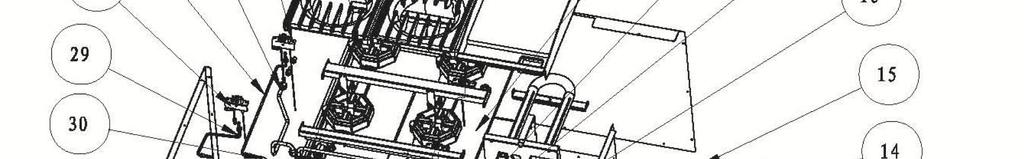
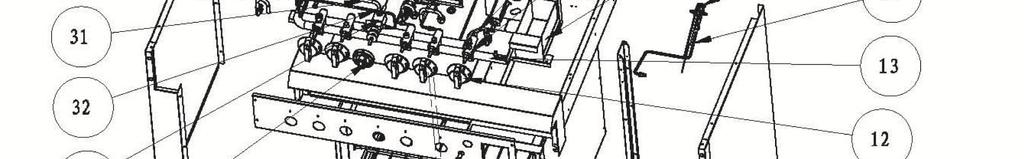
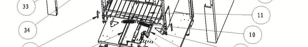
26 Explosion drawing 25
27 Spare Parts List NO. DESCRIPTION MODEL CODE QTY GH100-P GH100-N GE542-P GE542-N Door Assembly GH101-P GH101-N GH102-P GH102-N GE543-P GE543-N GE544-P GE544-N GH100-P GH100-N GE542-P GE542-N L-Connector GH101-P GH101-N GH102-P GH102-N GE543-P GE543-N GE544-P GE544-N GH100-P (oven) 1 GE542-P (oven) 1 GH100-P GE542-P GH101-P GH102-P Orifice GE543-P GE544-P GH100-N GH101-N GH102-N GE542-N GE543-N GE544-N GH100-P GH100-N GH101-P GH101-N Pilot Pipe Assembly - Oven GH102-P GH102-N GE542-P GE542-N GE543-P GE543-N GE544-P GE544-N GH100-P GH100-N GH101-P GH101-N Piezo Igniter GH102-P GH102-N GE542-P GE542-N GE543-P GE543-N GE544-P GE544-N GH100-P GH100-N GH101-P GH101-N Adjustable Foot GH102-P GH102-N GE542-P GE542-N GE543-P GE543-N GE544-P GE544-N Pilot rack GH100-P GH100-N ODS-Injector(0.01 for LPG) GH101-P GH101-N GH102-P GH102-N 7 1 GE542-P GE542-N ODS-Injector(0.02 for NG) GE543-P GE543-N GE544-P GE544-N GH100-P GH100-N GH101-P GH101-N U Burner Assembly GH102-P GH102-N GE542-P GE542-N GE543-P GE543-N GE544-P GE544-N
28 Spare Parts List (Continued) GH100-P GH100-N GH101-P GH101-N Door Hinge Assembly GH102-P GH102-N GE542-P GE542-N GE543-P GE543-N GE544-P GE544-N GH100-P GH100-N GE542-P GE542-N Door Spring GH101-P GH101-N GH102-P GH102-N GE543-P GE543-N GE544-P GE544-N GH100-P GH100-N GE542-P GE542-N Oven Rack GH101-P GH101-N GH102-P GH102-N GE543-P GE543-N GE544-P GE544-N GH100-P GH100-N GH101-P GH101-N Dial GH102-P GH102-N GE542-P GE542-N GE543-P GE543-N GE544-P GE544-N GH100-P GH100-N GH101-P GH101-N Manifold Assembly GH102-P GH102-N GE542-P GE542-N GE543-P GE543-N GE544-P GE544-N GH102-P GH102-N Pilot Pipe Assembly - Right GE542-P GE542-N GE543-P GE543-N GE544-P GE544-N Flame Device System GH102-P GH102-N ODS Injector-0.2 GE542-P GE542-N GE543-P GE543-N 2 ODS Injector GE544-P GE544-N 3 GH102-P GH102-N Oil Tray Assembly GE542-P GE542-N GE543-P GE543-N GE544-P GE544-N GH100-P GH100-N GH101-P GH101-N Safety Valve GH102-P GH102-N GE542-P GE542-N GE543-P GE543-N GE544-P GE544-N GH102-P GH102-N Main Pipe Assembly - Right GE542-P GE542-N GE543-P GE543-N GE544-P GE544-N GH100-P GH100-N Tray GH101-P GH101-N GH102-P GH102-N GE542-P GE542-N
29 Spare Parts List (Continued) GH102-P GH102-N Griddle Plate Assembly GE542-P GE542-N GE543-P GE543-N GE544-P GE544-N GH100-P GH100-N GE542-P GE542-N Flue Assembly GH101-P GH101-N GH102-P GH102-N GE543-P GE543-N GE544-P GE544-N GH100-P GH100-N GH101-P GH101-N Regulator GH102-P GH102-N GE542-P GE542-N GE543-P GE543-N GE544-P GE544-N GH100-P GH100-N Trivet GH101-P GH101-N GH102-P GH102-N GE543-P GE543-N GH100-P GH100-N Burner GH101-P GH101-N GH102-P GH102-N GE543-P GE543-N Flame Device System-Back GH100-P GH100-N ODS Injector-0.2 GH101-P GH101-N GH102-P GH102-N 3 ODS Injector GE543-P GE543-N 1 GH100-P GH100-N Main Pipe Back Assembly GH101-P GH101-N GH102-P GH102-N GE543-P GE543-N GH100-P GH100-N Pilot Pipe Back Assembly GH101-P GH101-N GH102-P GH102-N GE543-P GE543-N Flame Device System - GH100-P GH100-N Front GH101-P GH101-N 3 28 ODS Injector-0.2 GH102-P GH102-N LPG 2 ODS Injector-0.4 GE543-P GE543-N NG 1 GH100-P GH100-N Pilot Pipe Front Assembly GH101-P GH101-N GH102-P GH102-N GE543-P GE543-N GH100-P GH100-N Main Pipe Front Assembly GH101-P GH101-N GH102-P GH102-N GE543-P GE543-N GH100-P GH100-N GH101-P GH101-N Main Pipe Connect GH102-P GH102-N GE542-P GE542-N GE543-P GE543-N GE544-P GE544-N
30 Spare Parts List (Continued) 32 Pilot Pipe Connect 33 Thermostat Valve 34 Dial 35 Door Hinge 36 Main Pipe Connect Assembly 37 Pilot Pipe Connect Assembly GH100-P GH100-N GH101-P GH101-N GH102-P GH102-N GE542-P GE542-N GE543-P GE543-N GE544-P GE544-N GH100-P GH100-N GH101-P GH101-N GH102-P GH102-N GE542-P GE542-N GE543-P GE543-N GE544-P GE544-N GH100-P GH100-N GH101-P GH101-N GH102-P GH102-N GE542-P GE542-N GE543-P GE543-N GE544-P GE544-N GH100-P GH100-N GH101-P GH101-N GH102-P GH102-N GE542-P GE542-N GE543-P GE543-N GE544-P GE544-N GH100-P GH100-N GE542-P GE542-N GH101-P GH101-N GH102-P GH102-N GE543-P GE543-N GE544-P GE544-N GH100-P GH100-N GE542-P GE542-N GH101-P GH101-N GH102-P GH102-N GE543-P GE543-N GE544-P GE544-N
31 V1.Rev
32 Please keep this manual in a safe place for future use! 15 Badgally Road, Campbelltown NSW 2560
Thor Gas Fryer Installation and Operation Instructions
 Thor Gas Fryer Installation and Operation Instructions Model: GL165-P, GL165-N, GL166-P, GL166-N IMPORTANT FOR FUTURE REFERENCE Please complete this information and retain this manual for the life of the
Thor Gas Char-Broiler Installation and Operation Instructions
 Thor Gas Char-Broiler Installation and Operation Instructions Model:,,, IMPORTANT FOR FUTURE REFERENCE Please complete this information and retain this manual for the life of the equipment. For Warranty
USER MANUAL Gas Countertop Charbroilers
 Gas Countertop Charbroilers REVISED 2/209 382799 LAVA BRIQUETTE MODELS: 35CLCPG5NL, 35CLCPG24NL, 35CLCPG36NL, 35CLCPG48NL, 35CLCPG60NL, 35CLCPG72NL Congratulations on your purchase of Cooking Performance
USER MANUAL Gas Step Up Hot Plate
 USER MANUAL Gas Step Up Hot Plate MODELS: CK HPSU, CK HPSU, CK HPSU 0 / 07 IMPORTANT FOR FUTURE REFERENCE Please complete this information and retain this manual for the life of the equipment. For Warranty
Thor Gas Griddle Installation and Operation Instructions
 Thor Gas Griddle Installation and Operation Instructions Model:,,, IMPORTANT FOR FUTURE REFERENCE Please complete this information and retain this manual for the life of the equipment. For Warranty Service
Thor Gas Hot Plate Technical Service Manual
 Thor Gas Hot Plate Technical Service Manual Model: GH107-P, GH107-N IMPORTANT FOR FUTURE REFERENCE Please complete this information and retain this manual for the life of the equipment. For Warranty Service
Gas Cooktops (450mm Wide Hobs)
") Installation and Operation Manual Gas Cooktops (450mm Wide Hobs) Series RN8450G RNL8450G RNB8450G RNLB8450G RN8900G RNL8900G RNB8900G RNLB8900G Date Purchased Serial Number Dealer Service Provider For
Installation and Operation Manual Gas Cooktops (450mm Wide Hobs) Series RN8450G RNL8450G RNB8450G RNLB8450G RN8900G RNL8900G RNB8900G RNLB8900G Date Purchased Serial Number Dealer Service Provider For
Thor Gas Char-Broiler Technical Service Manual
 Thor Gas Char-Broiler Technical Service Manual Model: GH0-P, GH0-N, GH04-P, GH04-N N IMPORTANT FOR FUTURE REFERENCE Please complete this information and retain this manual for the life of the equipment.
Thor Gas Fryer Technical Service Manual
 Thor Gas Fryer Technical Service Manual Model: GH110-P, GH110-N,GH111-P,GH111-N IMPORTANT FOR FUTURE REFERENCE Please complete this information and retain this manual for the life of the equipment. For
Gas Range Static Oven
 Installation and Operation Manual Gas Range Static Oven Series RN8910G RNL8910G RNB8910G RNLB8910G Date Purchased Serial Number Dealer Service Provider 1 For use in GB & IE 232779-8 MANUFACTURED BY Moffat
Thor Gas Hob Installation and Operation Instructions
 Thor Gas Hob Installation and Operation Instructions 0359-15 PIN: 0359CN1290 BS EN203-1:2014 Gas heated catering equipment (TYPE A) Model: GL169-P, GL169-N IMPORTANT FOR FUTURE REFERENCE Please complete
GAS GRIDDLE GP514 GP516 GP518
 INSTALLATION AND OPERATION MANUAL GAS GRIDDLE GP514 GP516 GP518 232422-10 MANUFACTURED BY Moffat Limited Christchurch New Zealand INTERNATIONAL CONTACTS AUSTRALIA Moffat Pty Limited Web: www.moffat.com.au
STAR-MAX GAS GRIDDLES MODELS 615MA 624MA 636MA 648MA 615TA 624TA 636TA 648TA 624TSPA 636TSPA 648TSPA
 Star Manufacturing International Inc. 10 Sunnen Drive St. Louis, MO 63143 Phone: (314) 781-2777 Fax: (314) 781-3636 Installation and Operating Instructions 2M-Z1351 Rev. B 4/23/04 STAR-MAX GAS GRIDDLES
INSTALLATION & OPERATION MANUAL GAS CHARBROILERS
 INSTALLATION & OPERATION MANUAL GAS CHARBROILERS MODELS VCCB25 VCCB36 VCCB47 VCCB60 VCCB72 VCCB47 SCB25 SCB36 SCB47 SCB60 SCB72 SCB47 ITW Food Equipment Group, LLC 3600 North Point Blvd. Baltimore, MD
GAS TARGET TOP / STATIC OVEN RANGE
 INSTALLATION AND OPERATION MANUAL GAS TARGET TOP / STATIC OVEN RANGE G570 232426-8 MANUFACTURED BY Moffat Limited Christchurch New Zealand INTERNATIONAL CONTACTS AUSTRALIA Moffat Pty Limited E.Mail: vsales@moffat.com.au
STAR-MAX PROPANE GAS GRIDDLE
 Star Manufacturing International Inc. 10 Sunnen Drive St. Louis, MO 63143 Phone: (314) 781-2777 Fax: (314) 781-3636 Installation and Operating Instructions 2M-Z3793 Rev. B 3/28/03 STAR-MAX PROPANE GAS
GAS RANGE STATIC OVEN
 INSTALLATION AND OPERATION MANUAL GAS RANGE STATIC OVEN G504 G528 For use in GB, IE & DK 230103-15 MANUFACTURED BY Moffat Limited Rolleston 7675 New Zealand INTERNATIONAL CONTACTS AUSTRALIA Moffat Pty
OPERATOR S MANUAL Heavy Duty Counterline
 IMPORTANT FOR FUTURE REFERENCE Please complete this information and retain this manual for the life of the equipment: Model #: Serial #: Date Purchased: OPERATOR S MANUAL Heavy Duty Counterline Griddle
GAS GRIDDLE GP513 GP514 GP516 GP518
 INSTALLATION AND OPERATION MANUAL GAS GRIDDLE GP513 GP514 GP516 GP518 For use in GB & IE 229284-18 MANUFACTURED BY Moffat Limited Rolleston 7675 New Zealand INTERNATIONAL CONTACTS AUSTRALIA Moffat Pty
R-RCM & R-RSB SERIES
 R-RCM & R-RSB SERIES CHEESEMELTER & SALAMANDER BROILERS INSTALLATION - OPERATION - MAINTENANCE CHEESEMELTERS R-RCM-24 R-RCM-36 R-RCM-48 R-RCM-60 SALAMANDERS R-RSB-24 R-RSB-36 R-RSB-48 Telephone: (802)
Owner s Guide Installation & Operation
 Owner s Guide Installation & Operation Char Broiler HCH Series Hestan Commercial Corporation 3375 E. La Palma Ave Anaheim, CA 92806 (888) 905-7463 RETAIN THIS MANUAL FOR FUTURE REFERENCE P/N 002134 REV
INSTALLATION AND OPERATION MANUAL GAS GRIDDLE TOASTER G55T. For use in GB & IE
 INSTALLATION AND OPERATION MANUAL GAS GRIDDLE TOASTER G55T For use in GB & IE 228001-7 MANUFACTURED BY Moffat Limited Christchurch New Zealand INTERNATIONAL CONTACTS AUSTRALIA Moffat Pty Limited Web: www.moffat.com.au
Owner s Guide Installation & Operation
 Owner s Guide Installation & Operation Hot Top HHT Series Hestan Commercial Corporation 3375 E. La Palma Ave Anaheim, CA 92806 (888) 905-7463 RETAIN THIS MANUAL FOR FUTURE REFERENCE P/N 002130 REV 1 IMPORTANT
Gas Range Static Oven
 Installation and Operation Manual Gas Range Static Oven Series RN8510G RN8610G RN8810G RNL8510G RNL8610G RNL8810G RNB8510G RNB8610G RNB8810G RNLB8510G RNLB8610G RNLB8810G Date Purchased Serial Number Dealer
Gas Griddle Toaster. Model CT6 INSTALLATION AND OPERATION MANUAL
 Gas Griddle Toaster Model CT6 INSTALLATION AND OPERATION MANUAL 228009-6 MANUFACTURED BY Moffat Limited Christchurch New Zealand INTERNATIONAL CONTACTS AUSTRALIA Moffat Pty Limited E.Mail: vsales@moffat.com.au
GAS TARGET TOP / STATIC OVEN RANGE
 INSTALLATION AND OPERATION MANUAL GAS TARGET TOP / STATIC OVEN RANGE G570 For use in GB & IE 230096-8 MANUFACTURED BY Moffat Limited Christchurch New Zealand INTERNATIONAL CONTACTS AUSTRALIA Moffat Pty
OPERATING, INSTALLATION, SERVICE & PARTS MANUAL FOR MEDIUM DUTY GAS CHAR BROILERS MGB-A SERIES
 OPERATING, INSTALLATION, SERVICE & PARTS MANUAL FOR MEDIUM DUTY GAS CHAR BROILERS MGB-A SERIES VULCAN-HART COMPANY, P.O. BOX 696, LOUISVILLE, KY 40201-0696, TEL. (502) 778-2791 FORM 990503 (09-88) ! IMPORTANT
Radiant Steakhouse Broiler
 Owner s Manual IMPORTANT FOR FUTURE REFERENCE Please complete this information and retain this manual for the life of the equipment: Model #: Serial #: Date Purchased: Radiant Steakhouse Broiler Models
Installation and Operation Manual. Gas Griddle Toaster. Date Purchased. Serial Number. Dealer. Service Provider. For use in GB & IE
 Installation and Operation Manual Gas Griddle Toaster GT8600G GTL8600G GTB8600G GTLB8600G Date Purchased Serial Number Dealer Service Provider For use in GB & IE 228002-16 MANUFACTURED BY Moffat Limited
Radiant Salamander Broiler
 Owner s Manual IMPORTANT FOR FUTURE REFERENCE Please complete this information and retain this manual for the life of the equipment: Model #: Serial #: Date Purchased: Radiant Salamander Broiler Model
CSP6 - Gas Stock Pot INSTALLATION AND OPERATION MANUAL
 CSP6 - Gas Stock Pot INSTALLATION AND OPERATION MANUAL 240897-1 Moffat Limited Rolleston 7675 New Zealand AUSTRALIA Moffat Pty Limited E.Mail: vsales@moffat.com.au Main Office: (tel): +61 (03) 9518 3888
Gas Griddle GPL8450G GPL8600G GPL8900G GPL8120G GP8450G GP8600G GP8900G GP8120G. Installation and Operation Manual. 1 For use in GB & IE
 Installation and Operation Manual Gas Griddle GP8450G GP8600G GP8900G GP8120G GPL8450G GPL8600G GPL8900G GPL8120G Date Purchased Serial Number Dealer Service Provider 1 For use in GB & IE 228676-24 MANUFACTURED
Gas Target Top Range Static Oven
 Installation and Operation Manual Gas Target Top Range Static Oven RN8110G RNB8110G RNL8110G RNLB8110G Date Purchased Serial Number Dealer Service Provider 1 For use in GB & IE 228682-14 MANUFACTURED BY
Gas Cooktops. Models: C6 (600mm) C9 (900mm) INSTALLATION AND OPERATION MANUAL. For use in GB & IE
 C9 (900mm) INSTALLATION AND OPERATION MANUAL. For use in GB & IE") Gas Cooktops Models: C6 (600mm) C9 (900mm) INSTALLATION AND OPERATION MANUAL For use in GB & IE 230635-7 MANUFACTURED BY Moffat Limited Christchurch New Zealand INTERNATIONAL BRANCHES AUSTRALIA Moffat
Gas Cooktops Models: C6 (600mm) C9 (900mm) INSTALLATION AND OPERATION MANUAL For use in GB & IE 230635-7 MANUFACTURED BY Moffat Limited Christchurch New Zealand INTERNATIONAL BRANCHES AUSTRALIA Moffat
TRI-STAR INC SOUTH STANDARD AVENUE, SANTA ANA, CA Ph: Fax: MODEL #. OWNER S MANUAL
 TRI-STAR INC 2205 SOUTH STANDARD AVENUE, SANTA ANA, CA 92707 Ph: 714 424 9380 Fax: 714 424 9385 MODEL #. OWNER S MANUAL INSTALLATION OPERATION MAINTENANCE All equipments manufactured by Tri-star Inc. for
INSTALLATION AND OPERATION MANUAL ELECTRIC GRIDDLE EP514 EP516 EP518. For use in GB & IE
 INSTALLATION AND OPERATION MANUAL ELECTRIC GRIDDLE EP5 EP56 EP58 For use in GB & IE 35- MANUFACTURED BY Moffat Limited Rolleston 65 New Zealand INTERNATIONAL CONTACTS AUSTRALIA Moffat Pty Limited Web:
V SERIES HDR GAS RANGES
 SERVICE MANUAL ONE POWERFUL PACKAGE V SERIES HDR GAS RANGES TOPS Open Top Hot Top Griddle Top Work Surface BASES Standard Oven Convection Oven Cabinet Base - NOTICE - This manual is prepared for use by
Gas Cooktops. Installation and Operation Manual
 Installation and Operation Manual Gas Cooktops Series RN8200G RNL8200G RNB8200G RNLB8200G RN8400G RNL8400G RNB8400G RNLB8400G RN8600G RNL8600G RNB8600G RNLB8600G RN8800G RNL8800G RNB8800G RNLB8800G Date
Apollo Series Fryers
 INSTALLATION & OPERATION MANUAL Apollo Series Fryers ModelA-3-NAT A-3-LP (3 Burners Fryer) Model A-4-NAT A-4-LP (4 Burners Fryer) Model A-5-NAT A-5-LP ( 5 Burners Fryer) WARNING: IMPROPER INSTALLATION,
INSTALLATION AND OPERATION MANUAL GAS SKILLETS MODELS: GTS-30 GTS-40
 INSTALLATION AND OPERATION MANUAL GAS SKILLETS MODELS: GTS-30 GTS-40 CROWN FOOD SERVICE EQUIPMENT LTD. 70 OAKDALE ROAD, DOWNSVIEW, (TORONTO), ONTARIO, CANADA, M3N 1V9 TELEPHONE: (416) 746-2358, FAX: (416)
INSTALLATION AND OPERATION MANUAL GAS CHARGRILL G592 G593 G594 G596 G598. For use in GB, IE & DK
 ` INSTALLATION AND OPERATION MANUAL GAS CHARGRILL G592 G593 G594 G596 G598 For use in GB, IE & DK 228593-24 MANUFACTURED BY Moffat Limited Rolleston 7675 New Zealand INTERNATIONAL CONTACTS AUSTRALIA Moffat
MODELS: JGM, JGGM, JGT, JGTS, JGTSD, JGTSDS, JGGT, JGGTS, JTYG GRIDDLES AND JHP, JHPE HOT PLATES
 Jade Range LLC, A Middleby Company 2650 Orbiter Ave. Brea, CA 92821 Telephone (714) 961-2400 FAX (714) 961-2550 MODELS: JGM, JGGM, JGT, JGTS, JGTSD, JGTSDS, JGGT, JGGTS, JTYG GRIDDLES AND JHP, JHPE HOT
GAS STATIC OVEN RANGES
 INSTALLATION AND OPERATION MANUAL GAS STATIC OVEN RANGES G504 G528 232428-3 MANUFACTURED BY Moffat Limited Christchurch New Zealand INTERNATIONAL CONTACTS AUSTRALIA Moffat Pty Limited E.Mail: vsales@moffat.com.au
CINCINNATI, OH USA
 INSTRUCTION MANUAL Part No. 89731 Revised October 1997 CINCINNATI, OH 45241-4807 USA GAS SAFETY PRECAUTIONS Instructions on what to do when a user smells gas can be obtained from the local gas supplier.
Electric Griddle GPL8600E GPL8900E GPL8120E GP8600E GP8900E GP8120E. Installation and Operation Manual. For use in GB & IE
 Installation and Operation Manual Electric Griddle GP8600E GP800E GP80E GPL8600E GPL800E GPL80E Date Purchased Serial Number Dealer Service Provider For use in GB & IE 350-3 MANUFACTURED BY Moffat Limited
INSTALLATION, OPERATION & MAINTENANCE AVANTCO SERIES 177AG OWNER S MANUAL
 INSTALLATION, OPERATION & MAINTENANCE AVANTCO SERIES 177AG OWNER S MANUAL Manual Griddles: Radiant Charbroilers: Hot Plates: 177AG24MG 177AG36MG 177AG24RC 177AG36RC 177AGR212 All equipment manufactured
Installation and Operation Manual. Gas Target Top. Date Purchased. Serial Number. Dealer. Service Provider. For use in GB & IE
 Installation and Operation Manual Gas Target Top RN8100G RNL8100G RNB8100G RNLB8100G Date Purchased Serial Number Dealer Service Provider For use in GB & IE 228092-20 MANUFACTURED BY Moffat Limited Rolleston
Gas Cooktop Installation, User and Service Instructions GMS 955.1
 Gas Cooktop Installation, User and Service Instructions GMS 955.1 IMPORTANT: SAVE FOR LOCAL ELECTRICAL INSPECTOR S USE. READ AND SAVE THESE INSTRUCTIONS FOR FUTURE REFERENCE. OBSERVE ALL FEDERAL, STATE
ASSEMBLY INSTRUCTIONS HOODED GAS GRILL Model: UC-SBP
 ASSEMBLY INSTRUCTIONS HOODED GAS GRILL Model: UC-SBP FOR OUTDOOR USE ONLY PLEASE READ INSTRUCTIONS CAREFULLY BEFORE ASSEMBLY RETAIN THIS MANUAL FOR FUTURE REFERENCE WARNING Hazardous fire or explosion
INSTALLATION AND OPERATION MANUAL GAS SALAMANDER G91 G91B. For use in GB & IE
 INSTALLATION AND OPERATION MANUAL GAS SALAMANDER G91 G91B For use in GB & IE 231920-8 MANUFACTURED BY Moffat Limited Christchurch New Zealand INTERNATIONAL CONTACTS AUSTRALIA Moffat Pty Limited Web: www.moffat.com.au
GAS TARGET TOP RANGE/ CONVECTION OVEN
 INSTALLATION AND OPERATION MANUAL GAS TARGET TOP RANGE/ CONVECTION OVEN G576 232427-8 MANUFACTURED BY Moffat Limited Christchurch New Zealand INTERNATIONAL CONTACTS AUSTRALIA Moffat Pty Limited E.Mail:
INSTALLATION & OPERATION MANUAL
 INSTALLATION & OPERATION MANUAL EF SERIES ECONOFRY GAS FRYERS MODEL EF3 EF4 EF5 ML-52099 ML-114943 ML-114944 MODEL EF3 For additional information on Vulcan-Hart or to locate an authorized parts and service
GAS COOKER GAS OVEN SERIES. Owner s Manual Please read this manual carefully before operating your set. Retain it for future reference.
 GAS COOKER GAS OVEN SERIES Owner s Manual Please read this manual carefully before operating your set. Retain it for future reference. Record model number and serial number of the set. See the label attached
INSTALLATION GUIDE Dual Fuel Ranges
 INSTALLATION GUIDE Dual Fuel Ranges Contents Wolf Dual Fuel Ranges......................... 3 Safety Instructions............................ 4 Dual Fuel Range Specifications.................. 5 Dual Fuel
Gas Range Electric Static/Convection Ovens
 Installation and Operation Manual Gas Range Electric Static/Convection Ovens RN8910GE RN8910GEC RNL8910GE RNL8910GEC Date Purchased Serial Number Dealer Service Provider For use in GB & IE 232781-8 MANUFACTURED
Installation and Operation Manual. Gas Salamander SN8200G SN8200GB. Date Purchased. Serial Number. Dealer. Service Provider
 Installation and Operation Manual Gas Salamander SN8200G SN8200GB Date Purchased Serial Number Dealer Service Provider 232460-6 MANUFACTURED BY Moffat Limited Christchurch New Zealand INTERNATIONAL CONTACTS
INSTALLATION AND OPERATION MANUAL GAS SALAMANDER G91 G91B. For use in GB & IE
 om INSTALLATION AND OPERATION MANUAL GAS SALAMANDER G91 G91B For use in GB & IE 231920-11 MANUFACTURED BY Moffat Limited Rolleston 7675 New Zealand INTERNATIONAL CONTACTS AUSTRALIA Moffat Pty Limited Web:
USER MANUAL Stock Pot Range
 Stock Pot Range MODEL: 351CPGSPR18(L/N) 11/2017 This user s manual contains information and guidelines collected from years of industry experience. For optimal safety and efficient operation, please make
SAFETY PRECAUTIONS 1 11/09 EOPI 33643
 Use and Care of your new AGA Gas Fired Range Models: GC Open Flue Range (2 Oven) GC Direct Vent Range (2 Oven) GE Open Flue Range (4 Oven) GE Direct Vent Range (4 Oven) For U.S. and Canadian Markets NOTE:
Gas Range Convection Oven
 Installation and Operation Manual Gas Range Convection Oven RN8510GC RN8610GC RN8810GC RNL8510GC RNL8610GC RNL8810GC Date Purchased Serial Number Dealer Service Provider For use in GB, IE & DK 228680-23
PLEASE RETAIN THIS MANUAL FOR FUTURE REFERENCES. This equipment is design engineered for commercial use only
 OWNER S MANUAL INSTALLATION OPERATION MAINTENANCE FRYER SRF-40/50 All equipment manufactured by SIERRA CORP. is for use with the type of gas specified on the rating plate and for installation will be in
Gas Salamander. Model CS9 INSTALLATION AND OPERATION MANUAL. For use in GB & IE
 Gas Salamander Model CS9 INSTALLATION AND OPERATION MANUAL For use in GB & IE 230628-7 MANUFACTURED BY Moffat Limited Christchurch New Zealand INTERNATIONAL CONTACTS AUSTRALIA Moffat Pty Limited Web: www.moffat.com.au
OWNERS MANUAL INSTALLATION, OPERATION, & MAINTENANCE INSTRUCTIONS
 OWNERS MANUAL INSTALLATION, OPERATION, & MAINTENANCE INSTRUCTIONS 1128 Sherborn Street Corona, CA 92879-2089 (951) 281-1830 FAX (951) 281-1879 CIR SERIES RANGES & OVENS All Imperial Mfg. Co. equipment
User, Installation and Servicing Instructions. Silverlink 600 Gas Griddles GS4 and GS7 IS212 ECN3592
 User, Installation and Servicing Instructions Silverlink 600 Gas Griddles GS4 and GS7 IS212 ECN3592 INSTALLATION AND SERVICING INSTRUCTIONS Please read the following carefully before commencing work on
OWNERS MANUAL INSTALLATION, OPERATION, & MAINTENANCE INSTRUCTIONS
 OWNERS MANUAL INSTALLATION, OPERATION, & MAINTENANCE INSTRUCTIONS 1128 Sherborn Street Corona, CA 92879-2089 (951) 281-1830 (951) 281-1879 IPC SERIES PASTA COOKER All Imperial Mfg. Co. equipment is manufactured
PRO SERIES GAS FRYERS OWNER S MANUAL
 PRO SERIES GAS FRYERS OWNER S MANUAL MODELS: PF-1 PRO-FRYER, PF2 DUAL PRO-FRYER REVISED OCTOBER, 2009 *PLEASE RETAIN FOR FUTURE REFERENCE This appliance has been tested according to ANSI Z83.116-2009/CSA1.86-2009.
Owner s Guide Installation & Operation
 Owner s Guide Installation & Operation Fryer HFR Series Hestan Commercial Corporation 3375 E. La Palma Ave Anaheim, CA 92806 (888) 905-7463 RETAIN THIS MANUAL FOR FUTURE REFERENCE P/N 002137 REV 1 IMPORTANT
Instruction Manual for the APOLLO Gas Countertop Griddle Models: Manually Controlled: AMG-24, AMG-36, AMG-48 & AMG-60
 Instruction Manual for the APOLLO Gas Countertop Griddle Models: Manually Controlled: AMG-24, AMG-36, AMG-48 & AMG-60 For Service on Your Gas Griddle: Please call the APOLLO Service Department and ask
OWNER S MANUAL FOR BARBECUE GAS GRILL
 OWNER S MANUAL FOR BARBECUE GAS GRILL Model: CBA-401-A IF A REPLACEMENT IS NECESSARY, PLEASE CONTACT EITHER OUR CUSTOMER SERVICE DEPARTMENT OR YOUR LOCAL DEALER. THE USE OF UNAUTHORISED PARTS CAN CREATE
LP GAS PIZZA OVEN USER MANUAL
 LP GAS PIZZA OVEN USER MANUAL To reduce the risk of fire, burn hazard or other injury, read the USER MANUAL carefully and completely before using this appliance FOR OUTDOOR USE ONLY Before Cleaning, make
INSTRUCTION MANUAL. Destination Country: United Kingdom, Ireland. Gas Fired Salamander MODELS: SBE3418 & SBE3618
 INSTRUCTION MANUAL Destination Country: United Kingdom, Ireland MONTAGUE Gas Fired Salamander MODELS: SBE3418 & SBE3618 It is required by law that all gas appliances are installed by competent persons
ULTRA-MAX GAS RADIANT CHARBROILER. ULTRA-MAX GAS LAVA ROCK CHARBROILER MODELS 8024CBB, 8036CBB, 8048CBB, 8060CBB, and 8072CBB
 Star Manufacturing International Inc. 10 Sunnen Drive St. Louis, MO 63143 Phone: (314) 678-6303 Fax: (314) 781-2714 Installation and Operating Instructions 2M-Z20327 Rev. A 10/05/15 ULTRA-MAX GAS RADIANT
INSTALLATION & OPERATION MANUAL FOR Achiever Charbroilers
 INSTALLATION & OPERATION MANUAL FOR Achiever Charbroilers MODELS MLS VACB20 ML-135285 VACB25 ML-710543 VACB36 ML-710544 VACB47 ML-710545 VACB60 ML-710546 VACB72 ML-135286 www.vulcanhart.com MODELS MLS
GAS STATIC OVEN RANGES
 INSTALLATION AND OPERATION MANUAL GAS STATIC OVEN RANGES G504 G528 For use in GB, IE & DK 230103-11 MANUFACTURED BY Moffat Limited PO Box 10001 Christchurch New Zealand Ph: (03) 389 1007 Fax: (03) 389
Wok Cookers Instruction Manual
 Wok Cookers Instruction Manual Part No. DC100-09 Single Burner Wok Cooker Part No. DC200-09 Double Burner Wok Cooker IMPORTANT It is IMPORTANT that you read these instructions carefully and understand
ELECTRIC COMPACT DECK OVEN INSTALLATION - OPERATION - MAINTENANCE
 1415 ELECTRIC COMPACT DECK OVEN INSTALLATION - OPERATION - MAINTENANCE BLODGETT OVEN COMPANY www.blodgett.com 44 Lakeside Avenue, Burlington, Vermont 05401 USA Telephone: (802) 658-6600 Fax: (802)864-0183
GAS RANGE STATIC OVEN
 INSTALLATION AND OPERATION MANUAL GAS RANGE STATIC OVEN G505 G506 G508 232429-3 MANUFACTURED BY Moffat Limited PO Box 10001 Christchurch New Zealand Ph: (03) 389 1007 Fax: (03) 389 1276 WORLD-WIDE BRANCHES
GAS STOVE TOP.
 GAS STOVE TOP www.anvilworld.com ALL ANVIL EQUIPMENT COMES WITH A ONE YEAR WARRANTY ON COMPONENTS AND DEFECTIVE WORKMANSHIP. www.anvilworld.com LIMITED WARRANTY All equipment which is sold under ANVIL
FOR YOUR SAFETY FOR OUTDOOR USE ONLY PROPANE GAS. Model No. AH2069ODS, AH2063ODS
 Model No. AH2069ODS, AH2063ODS The ideal solution for extending the season of outdoor entertaining Creates a stylish and attractive ambience Direct ignition Includes a safety tip-over switch that halts
Sectional Deep Fryer
 IMPORTANT FOR FUTURE REFERENCE Please complete this information and retain this manual for the life of the equipment: Model #: Serial #: Date Purchased: OPERATOR S MANUAL Model P16-FR45 and P20-FR65 Sectional
GPC PASTA PRO INSTALLATION & USER OPERATION MANUAL
 GPC-14/18/20 GPC PASTA PRO INSTALLATION & USER OPERATION MANUAL GPC-18 shown with optional rinse station. NOTICE! After installation of your equipment, immediately contact your local gas supplier to obtain
VULCAN GAS RANGES RG-6 OPEN BURNER
 VULCAN GAS RANGES RG-6 OPEN BURNER Index: General data 2 Owner s Responsibility 3 authorised Vulcan catering Equipment Branches and dealers 3 Parts Ordering / Service Information 4 Prior to Installation
Using it in an enclosed space can kill you.
 38 X 56 GAS FIRE PIT - OWNER S MANUAL Carlisle Chat Fire Table Base Model # 00GBC7 (6877B) Fits 6877A Carlisle Chat Fire Table Top For Propane and *Natural Gas (*See Page 7) Certified to CSA International
PROF. RANGE COOKER MODEL: EPRC-9850FE/SS EPRC-9860E/SS. Owner s Manual Please read this manual carefully before operating your set.
 PROF. RANGE COOKER MODEL: EPRC-9850FE/SS EPRC-9860E/SS Owner s Manual Please read this manual carefully before operating your set. Retain it for future reference. Record model number and serial number
Patio Heater Model No. GM and GM
 Patio Heater Model No. GM124-003 and GM124-004 FEATURES: The ideal solution for extending the season for outdoor entertaining Maximum output 39.6 MJ/hr Direct ignition Adjustable heat output Safety tip-over
Apollo Series Fryers
 TABLE OF CONTENTS OPERATOR S MANUAL Apollo Series Fryers Model A-3-NAT A-3-LP (3 Burner Fryer) Model A-4-NAT A-4-LP (4 Burner Fryer) Model A-5-NAT A-5-LP ( 5 Burner Fryer) Improper installation, adjustment,
INSTALLATION AND OPERATION MANUAL GAS FIRED STEAMERS MODELS: GSX-5HE GSX-7HE GSX-10HE GSX-16HE
 INSTALLATION AND OPERATION MANUAL GAS FIRED STEAMERS MODELS: GSX-5HE GSX-7HE GSX-10HE GSX-16HE CROWN FOOD SERVICE EQUIPMENT LTD. 70 OAKDALE ROAD, DOWNSVIEW, (TORONTO), ONTARIO, CANADA, M3N 1V9 TELEPHONE:
INSTALLATION AND OPERATION MANUAL GAS COOKTOP. Series G512 G514 G516 G
 INSTALLATION AND OPERATION MANUAL GAS COOKTOP Series G512 G514 G516 G518 232423-5 MANUFACTURED BY Moffat Limited PO Box 10001 Christchurch New Zealand Ph: (03) 389 1007 Fax: (03) 389 1276 WORLD-WIDE BRANCHES
Electric Pasta Cooker
 Installation and Operation Manual Electric Pasta Cooker PC8140E PCB8140E PC8140E-7 PCB8140E-7 PCL8140E PCLB8140E PCL8140E-7 PCLB8140E-7 Date Purchased Serial Number Dealer Service Provider For use in GB
GAS STAINLESS COOKTOPS
 GAS STAINLESS COOKTOPS CG604D & CG905D models CG604DCG905D USER GUIDE HK SG Contents 1 EN Safety and warnings 2 Introduction 5 Using your cooktop 6 Cooking guidelines and cookware 8 Care and cleaning
GAS DECK OVENS INSTALLATION & OPERATING MANUAL
 GAS DECK OVENS INSTALLATION & OPERATING MANUAL MODELS: MB42, MB60, MB236, MB260, MB866, SD236, SD248, SD260, SD448, SD660, SD1048, SD1060, SD866, SD10866, WF42, WF60 FOR YOUR SAFETY DO NOT STORE OR USE
Operator s Manual CAYENNE GAS COUNTERTOP CHAR BROILER ENGLISH
 NGLISH CAYNN GAS COUNTRTOP CHAR BROILR Thank you for purchasing this Vollrath Counter Top Cooking quipment. Before operating the equipment, read and familiarize yourself with the following operating and
User Manual. 110 Cup (55 Cup Raw) Gas Rice Cooker. Model: 177GRCLP, 177GRCNAT 12/2018. Please read and keep these instructions. Indoor use only.
 Gas Rice Cooker. Model: 177GRCLP, 177GRCNAT 12/2018. Please read and keep these instructions. Indoor use only.") 110 Cup (55 Cup Raw) Gas Rice Cooker Intertek 5010781 Conforms to ANSI STD Z83.11-2016 Model: 177GRCLP, 177GRCNAT 12/2018 FOR YOUR SAFETY Do not store or use gasoline or other flammable vapors or liquids
110 Cup (55 Cup Raw) Gas Rice Cooker Intertek 5010781 Conforms to ANSI STD Z83.11-2016 Model: 177GRCLP, 177GRCNAT 12/2018 FOR YOUR SAFETY Do not store or use gasoline or other flammable vapors or liquids
INSTALLATION AND OPERATION MANUAL ELECTRIC COOKTOP E512 E514 E516. For use in GB & IE
 INSTALLATION AND OPERATION MANUAL ELECTRIC COOKTOP E512 E514 E516 For use in GB & IE 229356-6 MANUFACTURED BY Moffat Limited Rolleston 7675 New Zealand INTERNATIONAL CONTACTS AUSTRALIA Moffat Pty Limited
OPERATOR S MANUAL Sierra Fryers
 OPERATOR S MANUAL Sierra Fryers Model SRF-35/40 (3 Burner Fryer) Improper installation, adjustment, alteration, service or maintenance can cause property damage, injury or death. Read the installation,
UNDERCOUNTER REFRIGERATORS AND FREEZERS Installation, Operation and Maintenance Instructions
 UNDERCOUNTER REFRIGERATORS AND FREEZERS Installation, Operation and Maintenance Instructions Please read this manual completely prior to installing and operating this equipment. This manual describes how
FLAME HEATER PYRAMID CLFH-10SS OPERATION INSTRUCTIONS
 FLAME HEATER PYRAMID CLFH-10SS OPERATION INSTRUCTIONS www.colorato.net For outdoors use only Uses propane, butane or LPG only Reflector: 47x47 mm Total Height: 2250 mm Regulator s external pressure: 28-30
OWNERS MANUAL RON-36, RON-27, RON-24
 OWNERS MANUAL For Outdoor Use Only Installation, Operation, Maintenance Instructions And Parts List Models: RON-36, RON-27, RON-24 Royal Range of California, Inc. 3245 Corridor Drive, Eastvale, CA 91752
Installation and Operation Manual Covering Model 40S, 40C, 40D with Millivolt Gas Valve
 IMPORTANT FOR FUTURE REFERENCE Please complete this information and retain this manual for the life of the equipment: Model #: Serial #: Date Purchased: ENGLISH Installation and Operation Manual Covering
INSTRUCTION MANUAL BUILT-IN HOBS CIR900X
 INSTRUCTION MANUAL BUILT-IN HOBS CIR900X ENGLISH 3-19 Thank you for choosing our product. We advise you to read this manual carefully. It contains all necessary instructions for maintaining unaltered the