GAS STATIC OVEN RANGES
|
|
|
- Joella Rodgers
- 6 years ago
- Views:
Transcription


1 INSTALLATION AND OPERATION MANUAL GAS STATIC OVEN RANGES G504 G528 For use in GB, IE & DK
2 MANUFACTURED BY Moffat Limited PO Box Christchurch New Zealand Ph: (03) Fax: (03) WORLD-WIDE BRANCHES UNITED KINGDOM Blue Seal Unit 67, Gravelly Business Park Gravelly Park Birmingham West Midlands B24 8TQ Ph: (121) Fax: (121) UNITED STATES Moffat Inc 3765 Champion Blvd Winston-Salem North Carolina Ph: (336) Fax: (336) CANADA Serve Canada 22 Ashwarren Road Downview Ontario M3J1Z5 Toll Free: Ph: (416) Fax: (416) NEW ZEALAND Christchurch Auckland Moffat Limited Moffat Limited PO Box Waipuna Road 16 Osborne Street Mt Wellington Christchurch Auckland Ph: (03) Ph: (09) Fax: (03) Fax: (09) AUSTRALIA Victoria New South Wales Moffat Pty Limited Moffat Pty Limited 740 Springvale Road 3/142 James Ruse Drive, Rose Hill Mulgrave, Melbourne PO Box 913, Smithfield Victoria 3171 Sydney, N.S.W Ph: (03) Ph: (02) Fax: (03) Fax: (02) Western Australia Queensland Moffat Pty Limited Moffat Pty Limited 67 Howe Street 30 Prosperity Place Osbourne Park Geebung, Brisbane WA 6017 Queensland 4034 Ph: (08) Ph: (07) Fax: (08) Fax (07) The reproduction or copying of any part of this manual by any means whatsoever is strictly forbidden unless authorized previously in writing by the manufacturer. In line with policy to continually develop and improve its products, Moffat Ltd. reserves the right to change the specifications and design without prior notice. Copyright Moffat Ltd. March 2010
3 Contents Blue Seal Gas Static Oven Range G504 G528 Gas Range Static Oven mm. Gas Range Double Static Oven mm. Introduction... 2 Specification... 3 Model Numbers Covered in this Specification General Gas Supply Requirements Gas Connection Dimensions... 5 Installation... 6 Installation Requirements Unpacking Location Clearances Assembly Gas Connection Commissioning Operation Operation Guide Description of Controls Open Burners Griddles Oven Pilot Ignition Oven - Main Burner / Thermostat Turning the Oven to Stand-By (Pilot ON Only) Oven Shut Down Cleaning and Maintenance General After Each Use Daily Cleaning Weekly Cleaning Periodic Maintenance Fault Finding Gas Conversion and Specifications Conversion Procedure Gas Specifications Replacement Parts List
4 Introduction We are confident that you will be delighted with your BLUE SEAL GAS STATIC OVEN RANGE and it will become a most valued appliance in your commercial kitchen. To ensure you receive the utmost benefit from your new Blue Seal appliance, there are two important things you can do. Firstly: Please read the instruction book carefully and follow the directions given. The time taken will be well spent. Secondly: If you are unsure of any aspect of the installation, instructions or performance of your appliance, contact your BLUE SEAL dealer promptly. In many cases a phone call could answer your question. CE Only: These instructions are only valid if the country code appears on the appliance. If the code does not appear on the appliance, refer to the supplier of this appliance to obtain the technical instructions for adapting the appliance to the conditions for use in that country. WARNING: IMPROPER INSTALLATION, ADJUSTMENT, ALTERATION, SERVICE OR MAINTENANCE CAN CAUSE PROPERTY DAMAGE, INJURY OR DEATH. READ THE INSTALLATION, OPERATING AND MAINTENANCE INSTRUCTIONS THOROUGHLY BEFORE INSTALLING OR SERVICING THIS APPLIANCE. WARNING: INSTRUCTIONS TO BE FOLLOWED IN THE EVENT THE USER SMELLS GAS ARE TO BE POSTED IN A PROMINENT LOCATION. THIS INFORMATION SHALL BE OBTAINED BY CONSULTING THE LOCAL GAS SUPPLIER. WARNING: GREAT CARE MUST BE TAKEN BY THE OPERATOR TO USE THE EQUIPMENT SAFELY TO GUARD IT AGAINST RISK OF FIRE. THE APPLIANCE MUST NOT BE LEFT ON UNATTENDED. IT IS RECOMMENDED THAT A REGULAR INSPECTION IS MADE BY A COMPETENT SERVICEMAN TO ENSURE CORRECT AND SAFE OPERATION OF YOUR APPLIANCE IS MAINTAINED. DO NOT STORE OR USE GASOLINE OR OTHER FLAMMABLE VAPOURS OR LIQUIDS IN THE VICINITY OF THIS OR ANY OTHER APPLIANCE. DO NOT SPRAY AEROSOLS IN THE VICINITY OF THIS APPLIANCE WHILE IT IS IN OPERATION. CAUTION: This appliance is; For professional use and is to be used by qualified persons only. Only authorised service persons are to carry out installation, servicing and gas conversion operations. Components having adjustments protected (e.g. paint sealed) by the manufacturer should not be adjusted by the user / operator. DO NOT operate the appliance without the legs supplied fitted. 2
5 Specifications Model Numbers Covered in this Specification G504D [1] Gas Static Oven + 4 Open Burners. G504C [1] Gas Static Oven + 2 Open Burners mm Griddle. G504B Gas Static Oven mm Griddle. G528D [1] Double Gas Static Oven + 8 Open Burners. G528C [1] Double Gas Static Oven + 6 Open Burners mm Griddle. G528B [1] Double Gas Static Oven + 4 Open Burners mm Griddle. G528A [1] Double Gas Static Oven + 2 Open Burners mm Griddle. [1] - Open Burner Options; F - With Flame Failure Protection. PF - With Pilot and Flame Failure Protection. NOTE: The G528 consists of two ovens with a 1200mm wide Cook Top. General A heavy duty, general purpose gas range created for compact modular kitchens. It has a high option Cook Top / Griddle arrangement and is available on industrial adjustable feet or on robust rollers. Open Burners are available in either 'PF' (Pilot and Flame Failure) or 'F' (Flame Failure Only) options. Open Burner and Griddle options are fitted with individual flame failure for each open burner. Griddles are fitted with pilot, flame failure and piezo ignition as standard. Easy clean stainless steel external finish. The oven has pilot and flame failure and is fitted with piezo ignition as standard. Gas Supply Requirements - Non CE Only Natural Gas Input Rate (N.H.G.C.) - each Open Burner 28 MJ/hr (26,538 Btu/hr) - each 300 mm Griddle Section 21 MJ/hr (19,900 Btu/hr) - Oven 24 MJ/hr (22,748 Btu/hr) Supply Pressure kpa ( w.c.) Burner Operating Pressure 0.95 kpa (*) (3.7 w.c.) Gas Connection 3 / 4 B.S.P. Male LP Gas (Propane) 28 MJ/hr (26,538 Btu/hr) 21 MJ/hr (19,900 Btu/hr) 24 MJ/hr (22,748 Btu/hr) kpa (11-18 w.c.) 2.6 kpa (*) (10 w.c.) 3
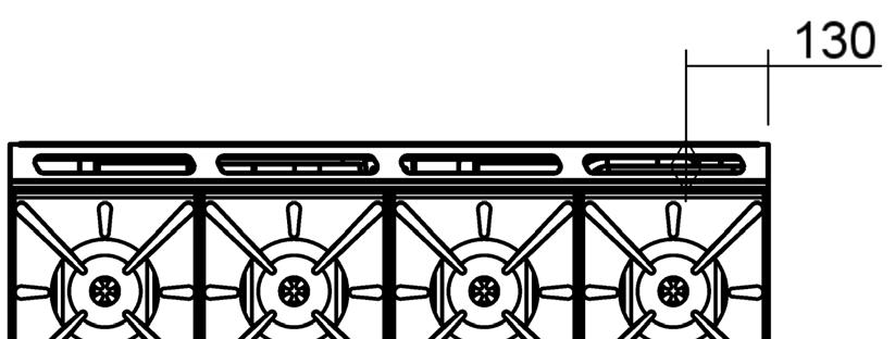
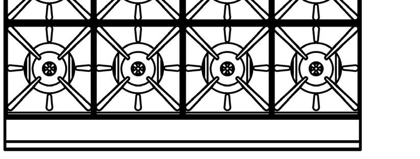
6 Specifications - CE Only Appliance Classification Category: II 2H3P (20, 30 / 37). Flue Type: A 1. Natural Gas (G20) Propane (G31) Open Burner (each) Griddle (each 300mm section) Oven Open Burner (each) Griddle (each 300mm section) Oven Heat Input (nett) Nominal 6.5 kw 5.5 kw 6.5 kw 6.5 kw 5.5 kw 6.0 kw Reduced 1.75 kw 1.85 kw 1.1 kw 1.75 kw 1.95 kw 1.05 kw Gas Rate (nett) Nominal 0.69 m 3 /hr 0.58 m 3 /hr 0.69 m 3 /hr 0.51 kg/hr 0.43 kg/hr 0.47 kg/hr Reduced 0.19 m 3 /hr 0.20 m 3 /hr 0.12 m 3 /hr 0.14 kg/hr 0.15 kg/hr 0.09 kg/hr Supply Pressure 20 mbar 30 / 37 mbar Burner Operating Pressure Gas Connection 9.5 mbar (*) 26 mbar (*) 3 / 4 B.S.P. Male * The burner operating pressure is to be measured at the manifold test point with two burners operating at full setting. The operating pressure is ex-factory set, through the appliance regulator and not to be adjusted, apart from when carrying out gas conversion, if required. (Refer to the Gas Conversion section for details). Gas Connection Gas supply connection point is located at the rear of the appliance, approximately 130 mm from the right hand side, 35 mm from the rear and 655 mm from the floor and is reached from beneath the appliance. (Refer to the Dimensions section). Connection is ¾" BSP male thread. 4
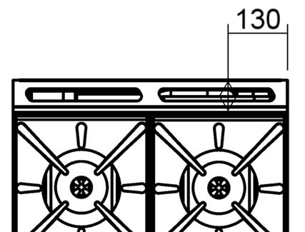
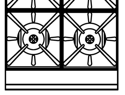
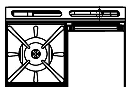
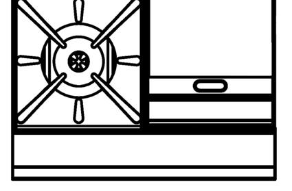
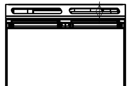
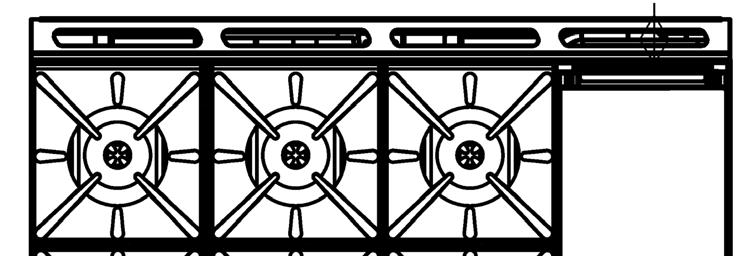
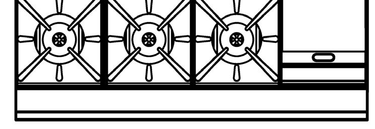
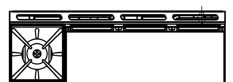
7 Dimensions G504 G504D G504C G504B 5
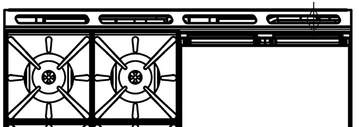
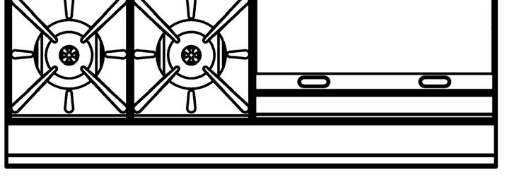
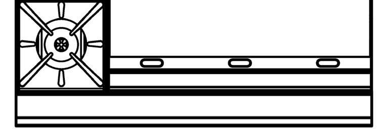
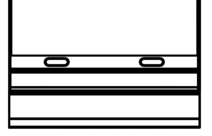
8 Dimensions G528 G528D G528C G528B G528A 6
9 Installation Installation Requirements NOTE: It is most important that this appliance is installed correctly and that operation is correct before use. Installation shall comply with local gas and health and safety requirements. This appliance shall be installed with sufficient ventilation to prevent the occurrence of unacceptable concentrations of health harmful substances in the room, the appliance is installed in. Blue Seal Ovens are designed to provide years of satisfactory service, and correct installation is essential to achieve the best performance, efficiency and trouble-free operation. This appliance must be installed in accordance with National installation codes and in addition, in accordance with relevant National / Local codes covering gas and fire safety. Australia: - AS Gas Installations. New Zealand: - NZS Gas Installation. United Kingdom: - Gas Safety (Installation & Use) Regulations BS Installation of Catering Appliances. - BS & 2 - Installation Flueing & Ventilation. Ireland: - IS Non - Domestic Gas Installations. Installations must be carried out by authorised persons only. Failure to install equipment to the relevant codes and manufacturer s specifications shown in this section will void the warranty. Components having adjustments protected (e.g. paint sealed) by the manufacturer are only allowed to be adjusted by an authorised service agent. They are not to be adjusted by the installation person. Unpacking Remove all packaging and transit protection from the appliance including all protective plastic coating from the exterior stainless steel panels. Check equipment and parts for damage. Report any damage immediately to the carrier and distributor. Report any deficiencies to the distributor who supplied the appliance. Check that the available gas and electrical supply is correct to that shown on the rating plate located on the front right hand corner of the bottom sill. Location 1. Installation must allow for a sufficient flow of fresh air for the combustion air supply. Combustion Air Requirements: G504 G528 Natural Gas (G20) 32 m 3 /hr 63 m 3 /hr LPG / Propane (G31) 33 m 3 /hr 65 m 3 /hr 2. Installation must include adequate ventilation means, to prevent dangerous build up of combustion products. 3. Never directly connect a ventilation system to the appliance flue outlet. 4. Position the appliance in its approximate working position. 5. All air for burner combustion is supplied from underneath the appliance. The legs must always be fitted and no obstructions placed on the underside or around the base of the appliance, as obstructions will cause incorrect operation and / or failure of the appliance. NOTE: Do not obstruct or block the appliances flue. Never directly connect a ventilation system to the appliance flue outlet. 7
10 Installation Clearances NOTE: Only non-combustible materials can be used in close proximity to this appliance. Combustible Surface Non Combustible Surface Left/Right hand side 250 mm (*) 0 mm Rear 100 mm 0 mm * Side clearances can be 50mm when the adjacent surface is at least 100 mm below the cooking surface. Assembly NOTE: All Models are delivered completely assembled. No further assembly is required. This appliance is fitted with adjustable feet to enable the appliance to be positioned securely and level. This should be carried out on completion of the gas connection. Refer to the Gas Connection section. Optional Accessories (Refer to Replacement Parts List) Plinth Kit. For installation details, refer to the instructions supplied with each kit. 1. Check that all the feet (or castors) are securely fitted. 2. Adjust the feet to make the convection oven range steady and level. Gas Connection NOTE: ALL GAS FITTING MUST ONLY BE CARRIED OUT BY AN AUTHORISED PERSON. 1. Blue Seal Ranges do not require an electrical connection, as they function totally on the gas supply only. 2. It is essential that the gas supply is correct for the appliance to be installed and that adequate supply pressure and volume are available. The following checks should therefore be made before installation:- a. Gas Type the appliance has been supplied for is shown on coloured stickers located above the gas connection and next to the rating plate. Check that this is correct for the gas supply the appliance is being installed for. The gas conversion procedure is detailed in this manual. b. Supply Pressure required for this appliance is shown in the Specifications section of this manual. Check the gas supply to ensure adequate supply pressure exists. c. Input Rate of this appliance is stated on the Rating Plate and in the Specifications section of this manual. The input rate should be checked against the available gas supply line capacity. Particular note should be taken if the appliance is being added to an existing installation. Rating Plate Location Fig 1 NOTE: It is important that adequately sized piping runs directly to the connection joint on the appliance with as few tees and elbows as possible to give maximum supply volume. 3. Fit the gas regulator supplied, into the gas supply line as close to the appliance as possible. 8

11 Installation NOTE: The gas pressure regulator provided with this appliance is convertible between Natural Gas and LPG as per the Gas Conversion Section in this manual. Ensure the regulator is converted to the correct gas type that the appliance will operate on. The regulator outlet pressure is fixed ex-factory for the gas type that the regulator is converted to and it is NOT to be adjusted. The regulator connections are 3 / 4 " BSP female. The connection to the appliance is 3 / 4 " BSP male. (Refer to the Specifications section for the gas supply location dimensions). NOTE: A Manual Isolation Valve must be fitted to the individual appliance supply line. 4. Correctly locate the appliance into its final operating position and using a spirit level, adjust the legs so that the appliance is level and at the correct height. 5. Connect the gas supply to the appliance. A suitable joining compound which resists the breakdown action of LPG must be used on every gas line connection, unless compression fittings are used. WARNING: DO NOT USE A NAKED FLAME TO CHECK FOR GAS LEAKAGES. 6. Check all gas connections for leakages using soapy water or other gas detecting equipment. 7. Check that the gas operating pressure is as shown in the Specifications section. NOTE: The operating pressure is to be measured at the manifold pressure test point and with two burners operating at the High Flame setting. 8. Turn off the mains gas supply and bleed the gas out of the appliance gas lines. 9. Turn on the gas supply and the appliance. 10. Verify the operating pressure remains correct. Manifold Pressure Test Point Commissioning Fig 2 1. Before leaving the new installation; a. Check the following functions in accordance with the operating instructions specified in the Operation section of this manual. Lighting the Griddle. Light the Open Burners. (F - Flame Failure Option). Light the Open Burners. (PF - Pilot and Flame Failure Option). Check the Low Fire burner operation. Oven Pilot Ignition. Oven Main Burner / Thermostat. Turning the Oven to Stand-By Mode. Oven Shut Down. b. Ensure that the operator has been instructed in the areas of correct lighting, operation, and shutdown procedure for the appliance. 2. This manual must be kept by the owner for future reference, and a record of Date of Purchase, Date of Installation and Serial Number of Unit recorded and kept with this manual. (These details can be found on the Rating Plate attached to the bottom right hand corner of the bottom sill. Refer to the Gas Connection section). NOTE: If for some reason it is not possible to get the appliance to operate correctly, shut off the gas supply and contact the supplier of this appliance. 9


. Lighting the Griddle. Oven Pilot Ignition.")
 OFF Position PILOT Burner HIGH Flame LOW Flame")
12 Operation Operation Guide CAUTION: This appliance is for professional use and is only to be used by qualified people. Only authorised service persons should be used to carry out installation, servicing or gas conversion operations. Components having adjustments protected (e.g. paint sealed) by the manufacturer should not be adjusted by the user/operator. 1. Blue Seal appliances have been designed to provide simplicity of operation and 100% safety protection. 2. Improper operation is therefore almost impossible, however bad operation practices can reduce the life of the appliance and produce a poor quality product. To use this appliance correctly please read the following sections carefully:- Lighting the Open Burners (F - Flame Failure Option). Lighting the Open Burners (PF - Pilot and Flame Failure Option). Lighting the Griddle. Oven Pilot Ignition. Oven Main Burner / Thermostat. Turning Oven to Stand-By (Pilot 'ON' Only). Oven Shut-Down. Description of Controls Gas Control Knobs (When Fitted with Griddle Option Only) OFF Position PILOT Burner HIGH Flame LOW Flame Griddle Piezo Igniter (When Fitted with Griddle Option Only) Gas Control Knobs (Open Burner Option) OFF Position HIGH Flame LOW Flame Gas Control Knob (Oven) OFF Position PILOT Burner Temperature Graduations 130 C to 270 C Fig 3 Oven Piezo Igniter (One per Oven) 10
13 Operation Open Burners NOTE: Only cooking pans from size Ø 150 mm to Ø 420 mm are suitable fo use on these open burners. Flame Failure Option (F-Models) Lighting the Open Burners Flame Failure Protection is incorporated for each burner by way of a thermo-electric system which will shut off the gas supply to that burner in the event that the burner goes out, so that un-burnt gas is not expelled. a. Select the burner required, depress and turn the corresponding gas control knob anti-clockwise to the HIGH position. b. With the gas control knob depressed, manually light the burner. c. Release the gas control knob after approximately seconds after lighting the burner. d. The burner should stay alight - if not, repeat Steps (a to (c above. e. To achieve simmer control, depress the gas control knob and rotate between the HIGH and LOW positions to achieve the temperature required. Turning 'OFF' the Open Burners a. When the main burner is not required, depress and turn the gas control knob clockwise back to the OFF position. The 'MAIN' burner will extinguish. Pilot and Flame Failure Option (PF-Models) Lighting the Open Burners These hobs are fitted with individual standing pilots for each open burner which allows the main burners to be turned 'ON' - 'OFF' without the need to manually re-light the burner each time that it is turned 'ON', as the burner will automatically light itself off the pilot burner. Flame Failure Protection is incorporated for each burner by way of a thermo-electric system which will shut off the gas supply to that burner in the event that the burner goes out, so that un-burnt gas is not expelled. a. Select the burner required, depress and turn the corresponding gas control knob anti-clockwise to the PILOT position. b. With the gas control knob depressed, manually light the pilot burner. c. Release the gas control knob after approximately seconds after lighting the pilot burner. d. The pilot burner should stay alight - if not, repeat Steps (a to (c above. e. Full Flame can now be achieved by depressing and rotating the gas control knob anti-clockwise to the first stop 'HIGH' flame position. f. Low flame can be achieved by depressing the gas control knob and rotating fully anti-clockwise to the LOW' flame position. g. To achieve simmer control, depress the gas control knob and rotate between the HIGH and LOW positions to achieve the temperature required. Turning 'OFF' the Open Burners / Pilots a. To turn 'OFF' the main burner, but keep the pilot burner alight, rotate the gas control knob to the 'PILOT' position. The main burner will extinguish and the pilot will remain alight. b. To turn 'OFF' the 'PILOT', depress and turn the gas control knob clockwise back to the OFF position. The 'PILOT' burner will extinguish. 11
14 Operation Griddle CAUTION: The griddle plate temperature reaches over 300 C in hottest points during normal operation at 'Full Flame' setting. These griddles are fitted with a pilot as a standard option and Flame Failure Protection, which is incorporated by way of a thermo-electric system for each main burner. Flame Failure Protection will shut off the gas supply to that burner in the event that the pilot for that burner goes out, so that un-burnt gas is not expelled. This is an important safety feature which is slowly becoming law throughout the world. Lighting the Griddle a. Depress the gas control knob and rotate anti-clockwise to the PILOT position. b. With the gas control knob depressed, press the piezo ignition button to ignite the pilot burner. Repeat Items 1 to 2 until the pilot is lit. c. Release the gas control knob approximately seconds after lighting the pilot. d. The pilot should now remain alight - if not, repeat Steps (a to (c above. e. Full Flame can now be achieved by depressing and rotating the gas control knob anti-clockwise to the first stop. f. Low flame can be achieved by depressing the gas control knob and rotating fully anti-clockwise to the Low Flame position. g. When the main burner is not required, depress and turn the gas control knob clockwise back to the OFF position. Turning 'OFF' the Griddle Burner / Pilot a. To turn 'OFF' the griddle, but keep the pilot burner alight, rotate the gas control knob to the 'PILOT' position. The griddle burner will extinguish and the pilot will remain alight. b. To turn 'OFF' the 'PILOT', depress and turn the gas control knob clockwise back to the OFF position. The 'PILOT' burner will extinguish. 12

15 Operation Oven Pilot Ignition! IMPORTANT DO NOT USE aluminium foil or trays directly on the cast iron sole plate(s). NEVER block or cover the openings on each side of the sole plate(s). 1. Open the oven door. Depress the thermostat control knob and rotate anti-clockwise to the PILOT position. 2. With the gas control knob depressed, press the piezo ignition button to ignite the pilot burner. Repeat Items 1 to 2 until the pilot is lit. 3. Release the gas control knob approximately seconds after lighting the pilot, until the pilot thermocouple is heated up by the pilot flame. 4. The pilot should now remain alight. If the pilot does not light, repeat Items 1 to 3 above. 5. View the pilot burner through the holes in the front of the burner box with the oven door open. See Fig 4. Pilot Burner viewing holes Fig 4 Oven - Main Burner / Thermostat 1. With the pilot burner alight, rotate the thermostat control knob anti-clockwise to the desired oven temperature setting required, this will regulate the gas supply to the burner. 2. To turn the main burner OFF, simply turn the thermostat control knob clockwise to the OFF position. Turning the Oven to Standby (Pilot ON Only) 1. To turn off the oven burner / heating, set the oven thermostat to the PILOT position, this will turn the oven OFF, but leave the oven pilot burner ON. 2. In this position the pilot burner will remain alight, but the main burner will not operate until the thermostat control knob is set to a temperature. 3. If pre-heating of the oven is required, set the thermostat control knob to temperature 190 C and allow 20 minutes before cooking in the oven to allow the oven to warm up. Oven Shut-Down 1. To turn the oven off to the PILOT position only, rotate the thermostat control knob clockwise until the pilot position is reached. In this position only the pilot burner will remain on. 2. To Shut Down the oven, depress and turn the thermostat control knob to the OFF position. This will turn OFF the oven and extinguish the pilot burner. To re-light the pilot burner, refer to Oven Pilot Ignition in this section. IMPORTANT Should any abnormal operation like; - ignition problems, - abnormal burner flame, - burner control problems, - partial or full loss of burner flame in normal operation, be noticed, the appliance requires IMMEDIATE service by a qualified service person and shall not be used until such service is carried out. 13
16 Cleaning and Maintenance CAUTION: Always turn off the gas supply before cleaning. This appliance is not water proof. Do not use water jet spray to clean interior or exterior of this appliance. General Clean the range regularly. A clean range looks better, will last longer and will perform better. Carbonised grease on the surface or between the trivets, griddle plates will hinder the transfer of heat from the cooking surface to the food. This will result in loss of cooking efficiency. NOTE: Each griddle option can be supplied with a scraper tool and a pack of blades for cleaning the griddle surface. These are not supplied with the griddle and have to be purchased separately. Refer to the 'Replacement Parts List' at the rear of this manual. WARNING: THE BLADES FITTED TO THE SCRAPER TOOL ARE EXTREMELY SHARP AND ARE TO BE USED WITH CARE. DO NOT use water on the trivets, burners and griddle plates while these items are still hot as warping and cracking may occur. Allow these items to cool down and then remove for cleaning. The entire trivets, griddle plates and burner caps can be dismantled for cleaning. NOTE: DO NOT use abrasive detergents, strong solvents or caustic detergents as they could corrode or damage the range. In order to prevent the forming of rust on the trivets, griddle plate (If fitted) and burners, ensure that any detergent or cleaning material has been completely removed after each cleaning. The appliance should be switched on briefly to ensure the griddle plates become dry. Oil or grease should be spread over the griddle surface in order to form a thin protective greasy film. To keep your range clean and operating at peak efficiency, follow the procedures shown below:- After Each Use CAUTION: Always ensure that an even pressure is applied over the whole surface of the scraper tool when using on the flat surface of the griddle, to prevent scoring of the surface. NEVER bang the sharp edge of the scraper tool on the flat surface of the griddle as this will damage the finish and invalidate the warranty. 1. Clean the griddle with a scraper tool to remove any food debris. 2. Always ensure that the scraper tool blades are changed regularly to ensure that the scraper tool works efficiently and prevents damage to the griddle plate surface. 3. Clean the range castings with a stiff nylon brush or a flexible spatula to remove any food debris. 14
17 Cleaning and Maintenance Daily Cleaning 1. The grease / spill trays should be checked and emptied frequently to prevent overflow and spillage. Remove the grease drawer while still warm so that the grease is in a liquid state. Empty any grease from the drawer and wash thoroughly in the same manner as any cooking utensil. 2. Remove the burner caps and bases, the trivets and thoroughly clean the splash back, interior and exterior surfaces of the range with hot water, a detergent solution and a soft scrubbing brush. 3. Brush griddle surface (optional - if fitted) with a soft bristled brush. Any carbon deposits should be removed using a scraper tool followed by wiping with a cloth to prevent build up of food deposits. 4. Dry the range thoroughly with a dry cloth and polish with a soft dry cloth. Weekly Cleaning NOTE: If the range usage is very high, we recommend that the weekly cleaning procedure is carried out on a more frequent basis. Ensure that protective gloves are worn during the cleaning process. DO NOT use harsh abrasive detergents, strong solvents or caustic detergents as they will damage the range and burners. DO NOT use water on the trivets, griddle plates and burners while they are still hot as cracking may occur. Allow these items castings to cool and remove for cleaning. DO NOT clean the burners in a dishwasher. Range Cooking Area a. Clean the range cooking area using a soft cloth moistened with a mild detergent and hot water solution. b. Baked on deposits or discolouration may require a good quality stainless steel cleaner or stainless steel wool. Always apply cleaner when the appliance is cold and rub in the direction of the grain. c. It should not be necessary to remove the splash guards covering the burner manifolds for cleaning purposes. These can be cleaned in situ. d. Remove the grease tray and clean with a mild anti bacterial detergent and hot water solution using a soft bristled brush. Clean control panel with a damp cloth moistened with a solution of mild detergent and water. e. Dry the grease tray thoroughly with a dry cloth. Griddle Plate - (Steel) NOTE: In order to prevent the forming of rust on the griddle plate, ensure the detergent or cleaning material has been entirely removed after each cleaning process. The appliance should be switched on briefly to ensure the griddle plates become dry. Oil or grease should be spread over the griddle surface in order to form a thin protective greasy film. CAUTION: Always ensure that an even pressure is applied over the whole surface of the scraper tool when using on the flat surface of the griddle, to prevent scoring of the surface. NEVER bang the sharp edge of the scraper tool on the flat surface of the griddle as this will damage the finish and invalidate the warranty. a. Remove and clean the grease / spill trays frequently to prevent over spills. b. Clean the griddle surface thoroughly with the optional scraper tool or a wire brush. If necessary use a griddle stone or a scotch bright pad on the griddle surface for the removal of stubborn or accumulated carbon deposits. c. A scraper tool can be used for the removal of stubborn carbon and deposits. d. Occasionally bleach the griddle plate with vinegar when the plate is cold. e. Clean with hot water, a mild detergent solution and a scrubbing brush. Dry all components thoroughly with a dry cloth. f. The griddle should be switched on briefly to ensure that the griddle plate becomes dry. A thin smear of cooking oil should be spread over the griddle in order to form a protective film. 15
 of the range.")
 from the top of the gas manifold, taking care not to damage the thermocouple (and pilot tube - PF Option)")

18 Cleaning and Maintenance Trivets and Burners a. Remove the trivets from the top of the appliance, taking note that the trivets are manufactured with a lip on one edge, the lip must always be fitted to the outer edge (front and back) of the range. (See Fig 10). b. Remove the burner cap and burner bowl (these are a loose fit to the manifold, see Fig 5) from the top of the gas manifold, taking care not to damage the thermocouple (and pilot tube - PF Option) fitted through the manifold splash guard. (Refer to Fig 8 for 'F' Option and Fig 9 for 'PF' Option). c. The trivets and burners should be cleaned with a mild detergent and hot water solution using a soft bristled brush. Dry thoroughly with a dry cloth. Burner Cap Burner Bowl Fig 5 Notice Difference in Profiles Trivet Supports a. Remove all the trivet supports from the top of the appliance. Note the orientation of the trivet support when removing. The trivet support front end side rail profiles are different from the rear end side rail profiles. (See the Note shown at Item a, in Re-Fitting the Components to the Range on the following page and Fig 6). b. The trivet supports should be cleaned with a mild detergent and hot water solution using a soft bristled brush. c. Dry the trivet supports thoroughly with a dry cloth. Stainless Steel Surfaces a. With the griddle plates and burners removed, clean the interior and exterior surfaces of the range with hot water, a mild detergent solution and a soft scrubbing brush. Note that the gas control knobs are a push fit onto the gas control valve spindles and can be removed to allow cleaning of the front control panel. b. Baked on deposits or discolouration may require a good quality stainless steel cleaner or stainless steel wool. Always apply cleaner when the appliance is cold and rub in the direction of the grain. c. It should not be necessary to remove the splash guards covering the burner manifolds for cleaning purposes. These can be cleaned in situ. d. Dry all components thoroughly with a dry cloth and polish with a soft dry cloth. e. To remove any discolouration, use an approved stainless steel cleaner or stainless steel wool. Always rub in the direction of the grain. f. Remove the grease tray and clean with a mild anti bacterial detergent and hot water solution using a soft bristled brush. g. Dry the grease tray thoroughly with a dry cloth. h. Dry all components thoroughly with a dry cloth and polish with a soft dry cloth. Re-Fitting the Components to the Range a. Refit the trivet supports to the range, ensuring that these are correctly fitted. Fig 6 Burner Bowl Locating Holes Fig 7 F - Option Burner Base Locates onto Cap Screw and over Flange Fig 8 PF - Option Pilot Burner Thermocouple Fig 5 Shown without Pilot Burner Shield fitted. 16 Fig 9
 and only one of the side rails seat into the cut-out in the range, whereas the rear end of the")
19 Cleaning and Maintenance NOTE: It is imperative that the trivet supports are correctly re-fitted to the unit to ensure that the trivets locate correctly and sit flush and level. NOTE that the trivet support front end side rail profiles are different at either side (Refer to Fig 6) and only one of the side rails seat into the cut-out in the range, whereas the rear end of the trivet support side rail profiles are the same and have 2 locating cut-outs. b. Refit the burner bowl onto the manifolds protruding through the splash guards, taking care not to damage the thermocouple (and pilot tube - PF Option) which is close to the manifold. Notice Lip on Trivet Edge Fig 10 NOTE: The burner bowl (cast item) has 2 locating holes drilled into the base flange (See Fig 7) these are to locate the burner bowl onto the cap screw on the gas manifold when re-fitting the burner bowl onto the gas manifold (Refer to Fig 8 {F-Option} and Fig 9 {PF-Option}). c. Refit the burner caps (cast brass) onto the burner bowls already fitted to the manifold. The burner cap is a loose fit into the burner bowl. d. Refit the trivets to the cook top, taking note that the trivets are manufactured with a lip on one edge, the lip must always be fitted to the outer edge (front and back) of the range. (See Fig 10). e. Refit the grease / spill tray(s) to the range. Oven Interior a. Do not use wire brushes, steel wool or other abrasive materials to clean the oven interior. b. Clean the oven regularly with a good quality domestic oven cleaner. c. Once a week, remove and clean any built up of grease etc. from the oven racks and the bottom spill over cover. d. Dry the oven thoroughly with a dry cloth and polish with a soft dry cloth. Periodic Maintenance NOTE: All maintenance operations should only be carried out by a qualified service person. To achieve the best results cleaning must be regular and thorough and all controls and mechanical parts should be checked and adjusted periodically by a qualified service person. If any small faults occur, have them attended to promptly. Don't wait until they cause a complete breakdown. It is recommended that the appliance is serviced every 6 months. Gas Control Valve Re-Greasing The gas control valve should be dismantled and greased every 6 months to ensure the correct operation of the gas control valve. To carry out this operation;- a. Remove the gas control knobs from the gas tap spindles by pulling the knobs away from the control panel. b. Remove the drip tray from the appliance. c. Remove the two screws on the underside of the control panel, securing the control panel to the hob. d. Remove the control panel from the front of the appliance. e. Remove the 2 screws holding shaft plate to gas control body and remove control shaft and plate. (See Fig 11). Note orientation of shaft for correct re-assembly. f. Using needle nose pliers or similar, pull out gas control spindle, again noting its orientation. g. Apply a suitable high temperature gas cock grease or lubricant such as ROCOL - A.S.P (Anti scuffing paste)/ Dry Moly Paste to the outside of spindle. (See Fig 12). h. Replace spindle and re-assemble the gas control in reverse order. i. Refit the control panel to the appliance and secure with 2 screws. j. Refit the knobs to the gas control valve spindles. Two Screws Fig 11 Spindle Fig 12 17
20 Fault Finding This section provides an easy reference guide to the more common problems that may occur during the operation of your appliance. The fault finding guide in this section is intended to help you correct, or at least accurately diagnose problems with your equipment. Although this section covers the most common problems reported, you may encounter a problem not covered in this section. In such instances, please contact your local authorised service agent who will make every effort to help you identify and resolve the problem. Please note that the service agent will require the following information:- The Model Trade Name and the Serial Number of the Appliance. (both can be found on the Technical Data Plate located on the appliance. Fault Possible Cause Remedy Pilot won t light. Pilot goes out when gas control knob released. Main burner will not light. Piezo Ignition spark is being generated but not sparking from the ignition electrode to the pilot burner hood. (Griddle Option Only) No gas supply. Blocked pilot injector. Releasing knob before the thermocouple has heated. Pilot flame too small. - Gas pressure too low. - Partially blocked pilot injector. Thermocouple connection to the gas control is loose or faulty. Thermocouple faulty. Electromagnet in the rear of the gas control unit is faulty. Incorrect supply pressure. Faulty gas control. HT lead damaged or broken. Check that the ignition electrode is not cracked and is correctly positioned. Piezo igniter faulty. Ensure gas isolation valve is turned on, and that bottles are not empty. Call the service provider. Hold knob in for at least 20 seconds following ignition of the pilot. Clean or replace the pilot injector. Tighten the thermocouple connection. Check that the thermo couple is producing between 20-30mV. Inspect and replace if not in good working order. Call the service provider. Call the service provider. Call the service provider. Repair or replace the HT lead. Re-position or replace the ignition electrode. Replace the piezo igniter. Call the service provider. NOTE: Components having adjustments protected (e.g. paint sealed) by the manufacturer, are only to be adjusted by an authorised service agent. They are not to be adjusted by an unauthorised service person. 18

 can only be adjusted in accordance with the following instructions and shall be re-sealed before re-commissioning this appliance.")

21 Gas Conversion and Specifications Conversion Procedure C AUTIO N : Ensure that the appliance is isolated from the gas supply before commencing servicing. Burner Cap NOTE: These conversions should only be carried out by qualified persons. All connections must be checked for leaks before re-commissioning the appliance. Adjustment of components that have adjustments / settings sealed (e.g. paint sealed) can only be adjusted in accordance with the following instructions and shall be re-sealed before re-commissioning this appliance. For all relevant gas specifications refer to the table at the end of this section. Burner Bowl Fig 13 Notice Difference in Profiles Open Burners ('F' - Flame Failure Option) Turn off the gas supply at the main supply. Remove the trivets from the top of the appliance, taking note that the trivets are manufactured with a lip on one edge, the lip must always be fitted to the outer edge (front and back) of the range. (See Fig 18) Remove the burner cap and burner bowl (these are a loose fit to the manifold) (See Fig 13) from the top of the gas manifold, taking care not to damage the thermocouple fitted through the manifold splash guard. Remove all the trivet supports from the top of the appliance. Note the orientation of the trivet support when removing. The front end side rail profiles are different from the rear end side rail profiles. (See Fig 14). Remove the splash guard covering the burner manifolds by unscrewing the two allan headed screws. (Refer to Fig 15). Carefully remove the splash guard taking care not to damage the thermocouples. Unscrew and remove the injectors (13 mm or ½ A/F) from the gas cocks. (See Fig 16) Determine the correct injector sizes for the corresponding gas from the rating plate affixed to the bottom right hand corner of the bottom sill. Replace with correct size injectors. Refer to Gas Specifications Table for injector sizes. Refit the splash guards over the gas cocks taking care not to damage the thermocouples and secure in position with the 2 allan headed screws. (See Fig 15). Refit the burner bowls and caps onto the manifolds protruding through the splash guards, taking care not to damage the thermocouple. Take note that the burner bowl (cast item) has 2 locating holes drilled into the base flange (See Fig 17), these are to locate the burner bowl onto the allen headed screw that secures the splash guard to the gas manifold. (See Fig 15). Turn on the gas supply at the mains, re-light the burners and check the flame size on the simmer LOW position. 19 Fig 14 Thermocouple Splash Guard Retaining Cap Screw Fig 15 Open Burner Injector Fig 16 Burner Bowl Locating Holes Fig 17

 of the cook top.")
. NOTE: The Low Fire Screw should be sealed with coloured paint on completion of the low fire adjustment. Low Fire Screw Fig 19 Open Burners ('PF' - Pilot & Flame Failure Option) 1. 2. 3.")
22 Gas Conversion and Specifications NOTE: The right hand gas control valve supplies the rear burner and the left hand gas control valve supplies the front burner Notice Lip on Refit all the trivet supports to the top of the appliance. Note the orientation of the trivet support when re-fitting. The trivet support front end side rail profiles are different from the rear end side rail profiles. (See Fig 14). Refit the trivets to the top of the appliance taking note that the trivets are manufactured with a lip on one edge, the lip must always be fitted to the outer edge (front and back) of the cook top. (See Fig 18). Fig 18 Pilot Supply Tube Low Fire Adjustment a. To adjust the open burner low fire adjustment, remove the gas control knobs from the front of the control panel. b. Adjust the low fire adjustment screw on the open burner gas control valves to obtain the desired flame size. (See Fig 19). NOTE: The Low Fire Screw should be sealed with coloured paint on completion of the low fire adjustment. Low Fire Screw Fig 19 Open Burners ('PF' - Pilot & Flame Failure Option) Turn OFF the gas supply at the main supply. Remove the trivets from the top of the appliance, taking note that the trivets are manufactured with a lip on one edge, the lip must always be fitted to the outer edge (front and back) of the cook top. (See Fig 18). Remove the burner caps and burner bowls (these are a loose fit to the manifold) from the top of the gas manifold. Remove all the trivet supports from the top of the appliance. Note the orientation of the trivet supports when removing. The trivet support front end side rail profiles are different from the rear end side rail profiles. (See Fig 14). Remove the pilot burner shields from over the pilot burners / thermocouples by removing the 2 screws securing the pilot burner shields to the splash guards. (See Fig 21). Remove the splash guards covering the burner manifolds by unscrewing the two allan headed screws. Carefully remove the splash guards taking care not to damage the pilot burner tubes and thermocouples protruding through the splash guard. Main Injectors a. Unscrew and remove the main injectors (½ A/F) from the gas cocks. (See Fig 22). b. Replace with the correct size injectors. Refer to the Gas Specifications table at the end of this section and the Rating Plate attached to the underside of the right hand side, front oven lower trim for correct injector sizes for the corresponding gas. Fig 20 2 Pilot Burner Shield Screws Pilot Burner Shield Fig 21 Main Injector Pilot Injector Plug 20 Fig 22


. f. Refit the splash guard over the gas cocks taking care not to damage the thermocouples and pilot burner tubes.")
23 Gas Conversion and Specifications NOTE Pilot Injectors a. Unscrew and remove the Pilot Injector Plug from the fitting at the end of the pilot injector tube using a 11 mm A/F spanner. (see Fig 23). b. Using a flat bladed screwdriver, unscrew and remove the pilot injector from the pilot injector housing. Take care not to lose the spring fitted in front of the injector. c. Remove existing pilot injector and replace with the correct size pilot injector for the gas type being used. Refer to the Gas Specifications table at the end of this section, for correct pilot injector sizes. d. Refit the spring and the correct pilot injector to the pilot injector housing. e. Screw the pilot injector fully home using a flat blade screwdriver and refit the pilot injector plug to the pilot injector housing and tighten in place using a 11 mm A/F spanner. (See Fig 23). f. Refit the splash guard over the gas cocks taking care not to damage the thermocouples and pilot burner tubes. Secure in position with the 2 allan headed screws. (Note that the splash guard for 'PF' models has a different cut-outs for pilot burner tubes. See Fig 24 & Fig 25). g. Refit the pilot burner tube shields over the pilot burner tubes / thermocouples and secure in place with the 2 securing screws. (See Fig 21). h. Refit the burner caps and burner bowls onto the manifolds protruding through the splash guards. Take note that the base part of the burner bowl has 2 locating holes drilled into the base flange, (See Fig 17).these are to locate the burner bowl onto the allen headed screws that secure the splash guard to the gas manifold. (See Fig 15). i. Refit all the trivet supports to the top of the appliance. Note the orientation of the trivet support when re-fitting as the front end side rail profiles are different from the rear end side rail profiles. (See Fig 14). j. Refit the trivets to the top of the appliance taking note that the trivets are manufactured with a lip on one edge, the lip must always be fitted to the outer edge (front and back) of the cook top. (see Fig 18). Pilot Injector Housing Pilot Injector Plug Cut-Out for Pilot Burner & Thermocouple Pilot Burner Shown without Pilot Burner Shield fitted. Fig 23 Fig 24 Thermocouple Fig 25 Low Fire Adjustment a. To adjust the open burner low fire adjustment, remove the gas control knobs from the front of the control panel. b. Adjust the low fire adjustment screw on the open burner gas control valves to obtain the desired flame size. (Refer to Fig 26). Low Fire Adjustment Screw Fig 26 NOTE: The Low Fire Screw should be sealed with coloured paint on completion of the low fire adjustment. 21

 spanner.")

24 Gas Conversion and Specifications Griddle Pilot Burner a. With the gas supply turned off at the main supply, remove the griddle plate section by lifting it straight off the cook top. b. Remove the gas control heat shield from around the griddle burner, this is just a push in fit. c. Disconnect the thermocouple and the piezo igniter from the mounting bracket. (For access purposes). (See Fig 28). d. Disconnect the pilot supply tube from the pilot burner with a 13 mm (½") spanner. (See Fig 28). e. Remove existing pilot injector and replace with the correct size for the gas being used. Refer to the Gas Specifications table at the end of this section, for correct injector sizes. f. Re-connect the pilot supply tube to the pilot burner with a 13 mm (½") spanner. (See Fig 28). g. Refit the piezo igniter and thermocouple to the mounting bracket. (See Fig 28). h. Repeat Items a) to g) for all griddle pilot burners. Gas Control Heat Shield Thermocouple Burner Securing Screw Fig 27 Piezo Igniter Main Burner a. Remove the main burner from the burner box by removing the securing screw at the end of the burner, this will reveal the main injector. (See Fig 29). b. Remove and replace the main burner injectors with correct size injectors. Refer to the Gas Specifications table at the end of this section, for correct injector sizes. c. Refit the burner to the griddle burner box. d. Refit the gas control heat shield to the griddle burner box. e. Refit the griddle plate section to the top of the cook top. f. Repeat Items a) to e) for all griddle main burners. g. Turn ON the gas supply at the mains, re-light the griddle burners and check the flame size on the LOW flame position. Pilot Burner Main Injector Pilot Burner supply tube Fig 28 Fig 15 Low Fire Adjustment a. To adjust the griddle burner LOW fire adjustment, remove the gas control knob from the front of the control panel. b. Adjust the Low Fire adjustment screw on the griddle gas control valve (Refer to Fig 30) only to obtain the desired flame size. Fig 29 Pilot Supply Tube NOTE: The Low Fire Screw should be sealed with coloured paint on completion of the low fire adjustment. Low Fire Screw Fig 30 22
. b. Remove the lintel from the oven. c. Open the oven door and remove the cast oven sole plate from inside the oven. d. Remove the single screw securing the oven burner to the main burner bracket in the oven and remove the main burner from the oven.")
. Setting the Main Burner Aeration Gap i.")


. c. Withdraw the pilot injector from the rear of the pilot burner. d.")
. e. Refit the sole plate to the oven. Oven Low Fire: a.")
25 Gas Conversion and Specifications Oven Main Injector: a. With the gas supply turned off at the main supply, unscrew and remove the 6 screws securing the lower lintel to the front of the oven. (See Fig 31). b. Remove the lintel from the oven. c. Open the oven door and remove the cast oven sole plate from inside the oven. d. Remove the single screw securing the oven burner to the main burner bracket in the oven and remove the main burner from the oven. e. The main injector will now be exposed and can be unscrewed and removed using a 13 mm ( 1/ 2 A/F) spanner. f. Remove the main injector (See Fig 32) and replace with the correct size injector. (Refer to the Gas Specifications table at the rear of this section). Setting the Main Burner Aeration Gap i. With the main burner removed from the oven, check the aeration gap on the shutter fitted to the main burner. ii. Ensure that the gap is set for the type of gas being used. Refer to the Gas Specifications table at the end of this section for the correct figures. iii. To adjust the aeration gap, slacken the clamp screw and rotate the aeration slide to the required position and tighten off the clamp screw. (Refer to Fig 33). g. Refit the main burner to the oven and secure to the main burner bracket with the single screw. Aeration Slide Shown with door removed for ease of viewing 6 screws Fig 31 Main Injector Static Oven Fig 32 Burner Adjustment Screw Pilot Injector: a. To remove the oven pilot injector, ensure that the cast oven sole plate has been removed from inside the oven. b. From inside the oven, unscrew the hex nut holding the pilot supply tube to the rear of the pilot burner. (Refer to Fig 34). c. Withdraw the pilot injector from the rear of the pilot burner. d. Replace the pilot injector with the correct sized pilot injector for the gas type being used (Refer to the Gas Specifications table at the rear of this section) and re-connect the pilot supply tube to the rear of the pilot burner. (Refer to Fig 34). e. Refit the sole plate to the oven. Oven Low Fire: a. When changing to a different type of gas, to change the oven LOW fire adjustment, remove the gas control knob from the front of the control panel. b. The low fire adjustment screw on the gas control valve (See Fig 35) should be replaced with the low fire adjustment screw shown in the Gas Specifications table for the gas type being used. NOTE: The Low Fire Screw should be sealed with coloured paint on completion of the low fire adjustment. Thermocouple Low Fire Adjustment Screw Pilot Burner Supply Tube Fig 33 Pilot Burner Fig Fig 35
GAS RANGE STATIC OVEN
 INSTALLATION AND OPERATION MANUAL GAS RANGE STATIC OVEN G505 G506 G508 232429-3 MANUFACTURED BY Moffat Limited PO Box 10001 Christchurch New Zealand Ph: (03) 389 1007 Fax: (03) 389 1276 WORLD-WIDE BRANCHES
GAS STATIC OVEN RANGES
 INSTALLATION AND OPERATION MANUAL GAS STATIC OVEN RANGES G504 G528 232428-3 MANUFACTURED BY Moffat Limited Christchurch New Zealand INTERNATIONAL CONTACTS AUSTRALIA Moffat Pty Limited E.Mail: vsales@moffat.com.au
INSTALLATION AND OPERATION MANUAL GAS COOKTOP. Series G512 G514 G516 G
 INSTALLATION AND OPERATION MANUAL GAS COOKTOP Series G512 G514 G516 G518 232423-5 MANUFACTURED BY Moffat Limited PO Box 10001 Christchurch New Zealand Ph: (03) 389 1007 Fax: (03) 389 1276 WORLD-WIDE BRANCHES
GAS RANGE STATIC OVEN
 INSTALLATION AND OPERATION MANUAL GAS RANGE STATIC OVEN G504 G528 For use in GB, IE & DK 230103-15 MANUFACTURED BY Moffat Limited Rolleston 7675 New Zealand INTERNATIONAL CONTACTS AUSTRALIA Moffat Pty
INSTALLATION AND OPERATION MANUAL GAS GRIDDLE TOASTER G55T. For use in GB & IE
 INSTALLATION AND OPERATION MANUAL GAS GRIDDLE TOASTER G55T For use in GB & IE 228001-7 MANUFACTURED BY Moffat Limited Christchurch New Zealand INTERNATIONAL CONTACTS AUSTRALIA Moffat Pty Limited Web: www.moffat.com.au
Gas Range Static Oven
 Installation and Operation Manual Gas Range Static Oven Series RN8910G RNL8910G RNB8910G RNLB8910G Date Purchased Serial Number Dealer Service Provider 1 For use in GB & IE 232779-8 MANUFACTURED BY Moffat
GAS TARGET TOP / STATIC OVEN RANGE
 INSTALLATION AND OPERATION MANUAL GAS TARGET TOP / STATIC OVEN RANGE G570 232426-8 MANUFACTURED BY Moffat Limited Christchurch New Zealand INTERNATIONAL CONTACTS AUSTRALIA Moffat Pty Limited E.Mail: vsales@moffat.com.au
Gas Cooktops. Models: C6 (600mm) C9 (900mm) INSTALLATION AND OPERATION MANUAL. For use in GB & IE
 C9 (900mm) INSTALLATION AND OPERATION MANUAL. For use in GB & IE") Gas Cooktops Models: C6 (600mm) C9 (900mm) INSTALLATION AND OPERATION MANUAL For use in GB & IE 230635-7 MANUFACTURED BY Moffat Limited Christchurch New Zealand INTERNATIONAL BRANCHES AUSTRALIA Moffat
Gas Cooktops Models: C6 (600mm) C9 (900mm) INSTALLATION AND OPERATION MANUAL For use in GB & IE 230635-7 MANUFACTURED BY Moffat Limited Christchurch New Zealand INTERNATIONAL BRANCHES AUSTRALIA Moffat
GAS TARGET TOP / STATIC OVEN RANGE
 INSTALLATION AND OPERATION MANUAL GAS TARGET TOP / STATIC OVEN RANGE G570 For use in GB & IE 230096-8 MANUFACTURED BY Moffat Limited Christchurch New Zealand INTERNATIONAL CONTACTS AUSTRALIA Moffat Pty
Gas Cooktops (450mm Wide Hobs)
") Installation and Operation Manual Gas Cooktops (450mm Wide Hobs) Series RN8450G RNL8450G RNB8450G RNLB8450G RN8900G RNL8900G RNB8900G RNLB8900G Date Purchased Serial Number Dealer Service Provider For
Installation and Operation Manual Gas Cooktops (450mm Wide Hobs) Series RN8450G RNL8450G RNB8450G RNLB8450G RN8900G RNL8900G RNB8900G RNLB8900G Date Purchased Serial Number Dealer Service Provider For
Gas Range Static Oven
 Installation and Operation Manual Gas Range Static Oven Series RN8510G RN8610G RN8810G RNL8510G RNL8610G RNL8810G RNB8510G RNB8610G RNB8810G RNLB8510G RNLB8610G RNLB8810G Date Purchased Serial Number Dealer
Gas Griddle Toaster. Model CT6 INSTALLATION AND OPERATION MANUAL
 Gas Griddle Toaster Model CT6 INSTALLATION AND OPERATION MANUAL 228009-6 MANUFACTURED BY Moffat Limited Christchurch New Zealand INTERNATIONAL CONTACTS AUSTRALIA Moffat Pty Limited E.Mail: vsales@moffat.com.au
INSTALLATION AND OPERATION MANUAL GAS CHARGRILL G592 G593 G594 G596 G598. For use in GB, IE & DK
 ` INSTALLATION AND OPERATION MANUAL GAS CHARGRILL G592 G593 G594 G596 G598 For use in GB, IE & DK 228593-24 MANUFACTURED BY Moffat Limited Rolleston 7675 New Zealand INTERNATIONAL CONTACTS AUSTRALIA Moffat
GAS GRIDDLE GP514 GP516 GP518
 INSTALLATION AND OPERATION MANUAL GAS GRIDDLE GP514 GP516 GP518 232422-10 MANUFACTURED BY Moffat Limited Christchurch New Zealand INTERNATIONAL CONTACTS AUSTRALIA Moffat Pty Limited Web: www.moffat.com.au
Gas Target Top Range Static Oven
 Installation and Operation Manual Gas Target Top Range Static Oven RN8110G RNB8110G RNL8110G RNLB8110G Date Purchased Serial Number Dealer Service Provider 1 For use in GB & IE 228682-14 MANUFACTURED BY
Installation and Operation Manual. Gas Griddle Toaster. Date Purchased. Serial Number. Dealer. Service Provider. For use in GB & IE
 Installation and Operation Manual Gas Griddle Toaster GT8600G GTL8600G GTB8600G GTLB8600G Date Purchased Serial Number Dealer Service Provider For use in GB & IE 228002-16 MANUFACTURED BY Moffat Limited
GAS GRIDDLE GP513 GP514 GP516 GP518
 INSTALLATION AND OPERATION MANUAL GAS GRIDDLE GP513 GP514 GP516 GP518 For use in GB & IE 229284-18 MANUFACTURED BY Moffat Limited Rolleston 7675 New Zealand INTERNATIONAL CONTACTS AUSTRALIA Moffat Pty
Gas Cooktops. Installation and Operation Manual
 Installation and Operation Manual Gas Cooktops Series RN8200G RNL8200G RNB8200G RNLB8200G RN8400G RNL8400G RNB8400G RNLB8400G RN8600G RNL8600G RNB8600G RNLB8600G RN8800G RNL8800G RNB8800G RNLB8800G Date
INSTALLATION AND OPERATION MANUAL GAS SALAMANDER G91 G91B. For use in GB & IE
 INSTALLATION AND OPERATION MANUAL GAS SALAMANDER G91 G91B For use in GB & IE 231920-8 MANUFACTURED BY Moffat Limited Christchurch New Zealand INTERNATIONAL CONTACTS AUSTRALIA Moffat Pty Limited Web: www.moffat.com.au
Gas Range Convection Oven
 Installation and Operation Manual Gas Range Convection Oven RN8510GC RN8610GC RN8810GC RNL8510GC RNL8610GC RNL8810GC Date Purchased Serial Number Dealer Service Provider For use in GB, IE & DK 228680-23
Gas Griddle GPL8450G GPL8600G GPL8900G GPL8120G GP8450G GP8600G GP8900G GP8120G. Installation and Operation Manual. 1 For use in GB & IE
 Installation and Operation Manual Gas Griddle GP8450G GP8600G GP8900G GP8120G GPL8450G GPL8600G GPL8900G GPL8120G Date Purchased Serial Number Dealer Service Provider 1 For use in GB & IE 228676-24 MANUFACTURED
Installation and Operation Manual. Gas Target Top. Date Purchased. Serial Number. Dealer. Service Provider. For use in GB & IE
 Installation and Operation Manual Gas Target Top RN8100G RNL8100G RNB8100G RNLB8100G Date Purchased Serial Number Dealer Service Provider For use in GB & IE 228092-20 MANUFACTURED BY Moffat Limited Rolleston
GAS TARGET TOP RANGE/ CONVECTION OVEN
 INSTALLATION AND OPERATION MANUAL GAS TARGET TOP RANGE/ CONVECTION OVEN G576 232427-8 MANUFACTURED BY Moffat Limited Christchurch New Zealand INTERNATIONAL CONTACTS AUSTRALIA Moffat Pty Limited E.Mail:
Installation and Operation Manual. Gas Salamander SN8200G SN8200GB. Date Purchased. Serial Number. Dealer. Service Provider
 Installation and Operation Manual Gas Salamander SN8200G SN8200GB Date Purchased Serial Number Dealer Service Provider 232460-6 MANUFACTURED BY Moffat Limited Christchurch New Zealand INTERNATIONAL CONTACTS
Gas Salamander. Model CS9 INSTALLATION AND OPERATION MANUAL. For use in GB & IE
 Gas Salamander Model CS9 INSTALLATION AND OPERATION MANUAL For use in GB & IE 230628-7 MANUFACTURED BY Moffat Limited Christchurch New Zealand INTERNATIONAL CONTACTS AUSTRALIA Moffat Pty Limited Web: www.moffat.com.au
INSTALLATION AND OPERATION MANUAL ELECTRIC GRIDDLE EP514 EP516 EP518. For use in GB & IE
 INSTALLATION AND OPERATION MANUAL ELECTRIC GRIDDLE EP5 EP56 EP58 For use in GB & IE 35- MANUFACTURED BY Moffat Limited Rolleston 65 New Zealand INTERNATIONAL CONTACTS AUSTRALIA Moffat Pty Limited Web:
INSTALLATION AND OPERATION MANUAL GAS SALAMANDER G91 G91B. For use in GB & IE
 om INSTALLATION AND OPERATION MANUAL GAS SALAMANDER G91 G91B For use in GB & IE 231920-11 MANUFACTURED BY Moffat Limited Rolleston 7675 New Zealand INTERNATIONAL CONTACTS AUSTRALIA Moffat Pty Limited Web:
Electric Griddle GPL8600E GPL8900E GPL8120E GP8600E GP8900E GP8120E. Installation and Operation Manual. For use in GB & IE
 Installation and Operation Manual Electric Griddle GP8600E GP800E GP80E GPL8600E GPL800E GPL80E Date Purchased Serial Number Dealer Service Provider For use in GB & IE 350-3 MANUFACTURED BY Moffat Limited
Installation and Operation Manual. Gas Pasta Cooker. Date Purchased. Serial Number. Dealer. Service Provider. For use in GB & IE
 Installation and Operation Manual Gas Pasta Cooker PC8140G PCL8140G Date Purchased Serial Number Dealer Service Provider For use in GB & IE 230008-10 MANUFACTURED BY Moffat Limited PO Box 10001 Christchurch
Gas Ranges Electric Static/Convection Oven
 Installation and Operation Manual Gas Ranges Electric Static/Convection Oven RN8510GE/GEC RN8610GE/GEC RN8810GE/GEC RNL8510GE/GEC RNL8610GE/GEC RNL8810GE/GEC Date Purchased Serial Number Dealer Service
Gas Range Electric Static/Convection Ovens
 Installation and Operation Manual Gas Range Electric Static/Convection Ovens RN8910GE RN8910GEC RNL8910GE RNL8910GEC Date Purchased Serial Number Dealer Service Provider For use in GB & IE 232781-8 MANUFACTURED
CSP6 - Gas Stock Pot INSTALLATION AND OPERATION MANUAL
 CSP6 - Gas Stock Pot INSTALLATION AND OPERATION MANUAL 240897-1 Moffat Limited Rolleston 7675 New Zealand AUSTRALIA Moffat Pty Limited E.Mail: vsales@moffat.com.au Main Office: (tel): +61 (03) 9518 3888
GAS GRIDDLE RANGES ELECTRIC OVEN
 INSTALLATION AND OPERATION MANUAL GAS GRIDDLE RANGES ELECTRIC OVEN GPE506 GPE56 GPE508 GPE58 For use in GB & IE 230112-16 MANUFACTURED BY Moffat Limited Rolleston 7675 New Zealand INTERNATIONAL CONTACTS
INSTALLATION AND OPERATION MANUAL ELECTRIC COOKTOP E512 E514 E516. For use in GB & IE
 INSTALLATION AND OPERATION MANUAL ELECTRIC COOKTOP E512 E514 E516 For use in GB & IE 229356-6 MANUFACTURED BY Moffat Limited Rolleston 7675 New Zealand INTERNATIONAL CONTACTS AUSTRALIA Moffat Pty Limited
Installation and Operation Manual. Gas Bratt Pan. Date Purchased. Serial Number. Dealer. Service Provider. For use in GB & IE
 Installation and Operation Manual Gas Bratt Pan BP8080G BP8080GE BP8120G BP8120GE BPL8080G BPL8080GE BPL8120G BPL8120GE Date Purchased Serial Number Dealer Service Provider For use in GB & IE 228688-16
Thor Gas Griddle Installation and Operation Instructions
 Thor Gas Griddle Installation and Operation Instructions Model:,,, IMPORTANT FOR FUTURE REFERENCE Please complete this information and retain this manual for the life of the equipment. For Warranty Service
E74 E76 E78 HOT FOOD DISPLAYS
 E74 E76 E78 HOT FOOD DISPLAYS -1- MANUFACTURED BY Moffat Limited PO Box 10001 Christchurch New Zealand Ph: (03) 389 1007 Fax: (03) 389 1276 WORLD-WIDE BRANCHES UNITED KINGDOM Blue Seal Units 6-7, Mount
Electric Cooktop. Series. Installation and Operation Manual
 Installation and Operation Manual Electric Cooktop Series RN8200E RNL8200E RNB8200E RNLB8200E RN8400E RNL8400E RNB8400E RNLB8400E RN8600E RNL8600E RNB8600E RNLB8600E Date Purchased Serial Number Dealer
Thor Gas Char-Broiler Installation and Operation Instructions
 Thor Gas Char-Broiler Installation and Operation Instructions Model:,,, IMPORTANT FOR FUTURE REFERENCE Please complete this information and retain this manual for the life of the equipment. For Warranty
Electric Pasta Cooker
 Installation and Operation Manual Electric Pasta Cooker PC8140E PCB8140E PC8140E-7 PCB8140E-7 PCL8140E PCLB8140E PCL8140E-7 PCLB8140E-7 Date Purchased Serial Number Dealer Service Provider For use in GB
User, Installation and Servicing Instructions. Silverlink 600 Gas Griddles GS4 and GS7 IS212 ECN3592
 User, Installation and Servicing Instructions Silverlink 600 Gas Griddles GS4 and GS7 IS212 ECN3592 INSTALLATION AND SERVICING INSTRUCTIONS Please read the following carefully before commencing work on
Thor Gas Hot Plate Technical Service Manual
 Thor Gas Hot Plate Technical Service Manual Model: GH107-P, GH107-N IMPORTANT FOR FUTURE REFERENCE Please complete this information and retain this manual for the life of the equipment. For Warranty Service
400mm Gas Fryer. Model CF4 INSTALLATION AND OPERATION MANUAL. For use in GB & IE
 400mm Gas Fryer Model CF4 INSTALLATION AND OPERATION MANUAL For use in GB & IE 230114-9 MANUFACTURED BY Moffat Limited Christchurch New Zealand INTERNATIONAL CONTACTS AUSTRALIA Moffat Pty Limited E.Mail:
GAS GRIDDLE INSTRUCTIONS MODEL: PGG6 MODEL: PGG7
 Page 1 of 17 GAS GRIDDLE INSTRUCTIONS MODEL: PGG6 MODEL: PGG7 SAFETY INSTRUCTIONS INSTALLATION INSTRUCTIONS OPERATION INSTRUCTIONS MAINTENANCE INSTRUCTIONS CONVERSION INSTRUCTIONS TECHNICAL DATA PARTS
Thor Gas Fryer Installation and Operation Instructions
 Thor Gas Fryer Installation and Operation Instructions Model: GL165-P, GL165-N, GL166-P, GL166-N IMPORTANT FOR FUTURE REFERENCE Please complete this information and retain this manual for the life of the
400mm Gas Fryer. Model FF18
 400mm Gas Fryer Model FF18 INSTALLATION AND OPERATION MANUAL 236859-6 MANUFACTURED BY Moffat Limited Rolleston 7675 New Zealand INTERNATIONAL CONTACTS AUSTRALIA Moffat Pty Limited E.Mail: vsales@moffat.com.au
HOW TO USE YOUR 2000 RANGE L.P.G. COOKER OR HOB UNIT
 HOW TO USE YOUR 2000 RANGE L.P.G. COOKER OR HOB UNIT CAUTION These instructions must be read and understood before proceeding with the installation and to avoid any possibility of accident it is essential
Installation, Operating and Servicing Instructions
 Installation, Operating and Servicing Instructions Opus 800 Gas Boiling Tops OG8003, OG8004 & OG8009 Please make a note of your product details for future use: Date Purchased: Model Number: Serial Number:
Thor Gas Hob Installation and Operation Instructions
 Thor Gas Hob Installation and Operation Instructions 0359-15 PIN: 0359CN1290 BS EN203-1:2014 Gas heated catering equipment (TYPE A) Model: GL169-P, GL169-N IMPORTANT FOR FUTURE REFERENCE Please complete
USHO COOKER INSTALLATION INSTRUCTIONS SAFETY INSTRUCTIONS USER INSTRUCTIONS MODEL: USHO. INSTRUCTION REF: IN152 ISSUE No. 4 DATE
 Page 1 of 11 INSTALLATION INSTRUCTIONS SAFETY INSTRUCTIONS USER INSTRUCTIONS USHO COOKER MODEL: USHO Page 2 of 11 WARNING To avoid scratching the highly polished exterior surface of this equipment whilst
STAR-MAX PROPANE GAS GRIDDLE
 Star Manufacturing International Inc. 10 Sunnen Drive St. Louis, MO 63143 Phone: (314) 781-2777 Fax: (314) 781-3636 Installation and Operating Instructions 2M-Z3793 Rev. B 3/28/03 STAR-MAX PROPANE GAS
User, Installation, Servicing and Conversion Instructions. Opus 700 Gas Oven Ranges OG7001 & OG7002 IS431 ECN3592
 User, Installation, Servicing and Conversion Instructions Opus 700 Gas Oven Ranges OG7001 & OG7002 IS431 ECN3592 Dear Customer, Thank you for purchasing this Lincat product. This is just one of over 450
STAR-MAX GAS GRIDDLES MODELS 615MA 624MA 636MA 648MA 615TA 624TA 636TA 648TA 624TSPA 636TSPA 648TSPA
 Star Manufacturing International Inc. 10 Sunnen Drive St. Louis, MO 63143 Phone: (314) 781-2777 Fax: (314) 781-3636 Installation and Operating Instructions 2M-Z1351 Rev. B 4/23/04 STAR-MAX GAS GRIDDLES
User, Installation and Servicing Instructions. Opus 700 Gas Griddle OG7201, OG7202, OG7203, OG7204, OG7207, OG7208 IS349 ECN3592
 User, Installation and Servicing Instructions Opus 700 Gas Griddle OG7201, OG7202, OG7203, OG7204, OG7207, OG7208 IS349 ECN3592 Dear Customer, Thank you for purchasing this Lincat product. This is just
OG7302 Salamander Grill
 OG7302 Salamander Grill USER, INSTALLATION, SERVICING AND CONVERSION INSTRUCTIONS For use in GB & IE IS370 ECN3280 1 Dear Customer, Thank you for purchasing this Lincat product. This is just one of over
GAS GRIDDLE INSTRUCTIONS MODEL: PGF GRIDDLES PGF 300, 600, 800, 1200
 Page 1 of 17 GAS GRIDDLE INSTRUCTIONS MODEL: PGF GRIDDLES PGF 300, 600, 800, 1200 VALIDATE WARRANTY SAFETY INSTRUCTIONS INSTALLATION INSTRUCTIONS OPERATION INSTRUCTIONS MAINTENANCE INSTRUCTIONS CONVERSION
F900 SERIES GAS CHARGRILL G9440, G9460, G9490, G User, installation and servicing instructions T Read these instructions before use
 F900 SERIES User, installation and servicing instructions GAS CHARGRILL G9440, G9460, G9490, G94120 Read these instructions before use DATE PURCHASED: MODEL NUMBER: SERIAL NUMBER: DEALER: SERVICE PROVIDER:
INSTALLATION AND OPERATION MANUAL 'VEE-RAY' GAS FRYERS GT60HPO
 INSTALLATION AND OPERATION MANUAL 'VEE-RAY' GAS FRYERS GT60HPO 229280-13 MANUFACTURED BY Moffat Limited Rolleston 7675 New Zealand INTERNATIONAL CONTACTS AUSTRALIA Moffat Pty Limited E.Mail: vsales@moffat.com.au
Induction Cooktop. Installation and Operation Manual IN8200E INL8200E INB8200E INLB8200E IN8400E INL8400E INB8400E INLB8400E. For use in GB & IE
 Installation and Operation Manual Induction Cooktop IN8200E INL8200E INB8200E INLB8200E IN8400E INL8400E INB8400E INLB8400E Date Purchased Serial Number Dealer Service Provider 1 For use in GB & IE 2350343
HOW TO USE YOUR 4500 RANGE L.P.G. COOKER OR HOB UNIT
 HOW TO USE YOUR 4500 RANGE L.P.G. COOKER OR HOB UNIT If the appliance does not operate correctly contact your supplier Or Leisure Products (Bolton) Ltd Holly Street, Bolton, BL1 8QR. England. ~~~~ For
Belling. Gas Hob GHU573 - GHU573T GHU70GE - GHU70TGE - GHU70GC GHU70TGC - GHU60GC INSTALLATION AND USER INSTRUCTIONS
 Belling Gas Hob GHU573 - GHU573T GHU70GE - GHU70TGE - GHU70GC GHU70TGC - GHU60GC INSTALLATION AND USER INSTRUCTIONS Note: This appliance is supplied for use with Natural Gas and can be converted to LPG
INSTALLATION / OPERATION MANUAL
 INSTALLATION / OPERATION MANUAL SM-50T SM-80T SM-120T Spiral Mixers 1 F26448-4 WORLD-WIDE BRANCHES UNITED KINGDOM Blue Seal Unit 67 Gravelly Business Park Gravelly Park Birmingham B24 8TQ Ph: (121) 327
THE INSTRUCTIONS IN THIS MANUAL APPLY TO KENT GAS FIRES. CONTENTS:-
 THE INSTRUCTIONS IN THIS MANUAL APPLY TO KENT GAS FIRES. THE MODELS COVERED ARE:- For use with Natural Gas:- KENT ESTATE NG, KENT ULTIMA NG For use with Liquid Propane Gas (LPG):- KENT ESTATE LP, KENT
Glen Dimplex Professional Appliances: Salamander Grill (GB/IE)
") Glen Dimplex Professional Appliances: Salamander Grill (GB/IE) This appliance must be installed by a competent person in compliance with the installation and servicing instructions and national regulations
Glen Dimplex Professional Appliances: Salamander Grill (GB/IE) This appliance must be installed by a competent person in compliance with the installation and servicing instructions and national regulations
HOW TO USE YOUR 2500 RANGE L.P.G. COOKER OR HOB UNIT
 HOW TO USE YOUR 2500 RANGE L.P.G. COOKER OR HOB UNIT CAUTION These instructions must be read and understood before proceeding with the installation and to avoid any possibility of accident it is essential
Wok Cookers Instruction Manual
 Wok Cookers Instruction Manual Part No. DC100-09 Single Burner Wok Cooker Part No. DC200-09 Double Burner Wok Cooker IMPORTANT It is IMPORTANT that you read these instructions carefully and understand
Thor Gas Char-Broiler Technical Service Manual
 Thor Gas Char-Broiler Technical Service Manual Model: GH0-P, GH0-N, GH04-P, GH04-N N IMPORTANT FOR FUTURE REFERENCE Please complete this information and retain this manual for the life of the equipment.
Pizza Oven with Stand
 Pizza Oven with Stand Cooks up to 3 pizzas at a time Use to cook a variety of food Easy clean vitreous enamel interior Model No. P0104 Powerful 22MJ/h stainless steel burner Viewing window and temperature
GAS GRIDDLE INSTRUCTIONS MODEL: PGF GRIDDLES GGP6.4, 6.6, 6.8, 6.10
 Page 1 of 18 GAS GRIDDLE INSTRUCTIONS MODEL: PGF GRIDDLES GGP6.4, 6.6, 6.8, 6.10 VALIDATE WARRANTY SAFETY INSTRUCTIONS INSTALLATION INSTRUCTIONS OPERATION INSTRUCTIONS MAINTENANCE INSTRUCTIONS CONVERSION
These Appliances must be installed and serviced by a competent person as stipulated by the Gas Safety (Installation & Use) Regulations.
 Regulations.") G350/11 and 12 FREESTANDING FRYERS INSTALLATION and SERVICING INSTRUCTIONS These Appliances must be installed and serviced by a competent person as stipulated by the Gas Safety (Installation & Use) Regulations.
G350/11 and 12 FREESTANDING FRYERS INSTALLATION and SERVICING INSTRUCTIONS These Appliances must be installed and serviced by a competent person as stipulated by the Gas Safety (Installation & Use) Regulations.
Thor Gas Oven Installation and Operation Instructions
 Thor Gas Oven Installation and Operation Instructions Model: GH100-P, GH100-N, GH101-P, GH101-N, GH102-P, GH102-N, GE542-P, GE542-N, GE543-P, GE543-N, GE544-P, GE544-N IMPORTANT FOR FUTURE REFERENCE Please
OG7005 Solid Top Gas Oven Range
 OG7005 Solid Top Gas Oven Range USER, INSTALLATION, SERVICING AND CONVERSION INSTRUCTIONS For use in GB & IE IS323 ECN3145 1 Dear Customer, Thank you for purchasing this Lincat product. This is just one
BESTLINK INTERNATIONAL. User instructions Maintenance instructions Installation & service instructions
 GMK 10023 AS 4551 BESTLINK INTERNATIONAL User instructions Maintenance instructions Installation & service instructions Cooktop models: BLGSW905CF BLGSW905C BLGSW705CF BLGSW705C BLGSW704CF BLGSW704C BLGSW60CF
VULCAN GAS RANGES RG-6 OPEN BURNER
 VULCAN GAS RANGES RG-6 OPEN BURNER Index: General data 2 Owner s Responsibility 3 authorised Vulcan catering Equipment Branches and dealers 3 Parts Ordering / Service Information 4 Prior to Installation
USER MANUAL Gas Countertop Charbroilers
 Gas Countertop Charbroilers REVISED 2/209 382799 LAVA BRIQUETTE MODELS: 35CLCPG5NL, 35CLCPG24NL, 35CLCPG36NL, 35CLCPG48NL, 35CLCPG60NL, 35CLCPG72NL Congratulations on your purchase of Cooking Performance
Patio Heater Model No. GM and GM
 Patio Heater Model No. GM124-003 and GM124-004 FEATURES: The ideal solution for extending the season for outdoor entertaining Maximum output 39.6 MJ/hr Direct ignition Adjustable heat output Safety tip-over
INSTALLATION AND OPERATION MANUAL 'VEE-RAY' GAS FRYERS GT45 GT46 GT60. For use in GB & IE
 INSTALLATION AND OPERATION MANUAL 'VEE-RAY' GAS FRYERS GT45 GT46 GT60 For use in GB & IE 228574-10 MANUFACTURED BY Moffat Limited PO Box 10001 Christchurch New Zealand Ph: (03) 389 1007 Fax: (03) 389 1276
USER S GUIDE FOR OVEN RANGE AND COMBINATION
 USER S GUIDE FOR OVEN RANGE AND COMBINATION NAME OF APPLIANCE SPECIFICATION SUPERTRON COMMERCIAL OVEN MODEL NO. 4BT-OV-600, 6BT-OV-900, 8BT-OV-1200, 10BT-OV-1500 MANUFACTURED BY TU S BROS PTY LTD 77 MAIN
SAFETY PRECAUTIONS 1 11/09 EOPI 33643
 Use and Care of your new AGA Gas Fired Range Models: GC Open Flue Range (2 Oven) GC Direct Vent Range (2 Oven) GE Open Flue Range (4 Oven) GE Direct Vent Range (4 Oven) For U.S. and Canadian Markets NOTE:
Installation, Operating and Servicing Instructions. Opus 800 Gas Open Top Oven Ranges OG8001 & OG8002
 Installation, Operating and Servicing Instructions Opus 800 Gas Open Top Oven Ranges OG8001 & OG8002 Please make a note of your product details for future use: Date Purchased: Model Number: Serial Number:
GARLAND GAS CHARGRILL OWNER S MANUAL. Country of Destination GB and IE. Manual Part No: Gas Chargrill - 1 Manual Rev No: 1
 GARLAND GAS CHARGRILL OWNER S MANUAL Country of Destination GB and IE Manual Part No: 932067-08 Gas Chargrill - 1 IMPORTANT CUSTOMER INFORMATION Please check that the gas taps will press and release freely
INSTRUCTION MANUAL. Destination Country: United Kingdom, Ireland. Gas Fired Salamander MODELS: SBE3418 & SBE3618
 INSTRUCTION MANUAL Destination Country: United Kingdom, Ireland MONTAGUE Gas Fired Salamander MODELS: SBE3418 & SBE3618 It is required by law that all gas appliances are installed by competent persons
Curl Flow II Slicer. Operating and Training Manual Date Purchased; Serial Number; Service Provider Number;
 Curl Flow II Slicer Operating and Training Manual Date Purchased; Serial Number; Service Provider Number; 026726-1 MANUFACTURED BY Moffat Pty Ltd 620 Old Gympie Road Narangba 4504 Queensland Australia
ASSEMBLY INSTRUCTIONS HOODED GAS GRILL Model: UC-SBP
 ASSEMBLY INSTRUCTIONS HOODED GAS GRILL Model: UC-SBP FOR OUTDOOR USE ONLY PLEASE READ INSTRUCTIONS CAREFULLY BEFORE ASSEMBLY RETAIN THIS MANUAL FOR FUTURE REFERENCE WARNING Hazardous fire or explosion
Outdoor Tabletop Heater TTH20 Series
 Outdoor Tabletop Heater TTH20 Series FEATURES: The ideal solution for extending the outdoor entertaining season Creates a stylish and attractive ambience Casts an approximate 1 to 1.5 metre circle of radiant
GAS COOKER GAS OVEN SERIES. Owner s Manual Please read this manual carefully before operating your set. Retain it for future reference.
 GAS COOKER GAS OVEN SERIES Owner s Manual Please read this manual carefully before operating your set. Retain it for future reference. Record model number and serial number of the set. See the label attached
Owner s Guide Installation & Operation
 Owner s Guide Installation & Operation Char Broiler HCH Series Hestan Commercial Corporation 3375 E. La Palma Ave Anaheim, CA 92806 (888) 905-7463 RETAIN THIS MANUAL FOR FUTURE REFERENCE P/N 002134 REV
Installation and Operating Instructions
 Installation and Operating Instructions Models: Verso 4G Hob As part of Parmco Appliances commitment to improving and updating product ranges, we reserve the right to alter, change and update technical
INSTALLATION / OPERATION MANUAL
 INSTALLATION / OPERATION MANUAL BM10 Planetary Mixer 1 F26290-4 WORLD-WIDE BRANCHES UNITED KINGDOM Blue Seal 67 Gravelly Business Park Gravelly Park Birmingham West Midlands B24 8TQ Ph: (121) 327 5575
2 BURNER LP GAS STOVE OPERATING INSTRUCTIONS
 BURNER LP GAS STOVE OPERATING INSTRUCTIONS Part No. 5090 IMPORTANT Read these instructions for use carefully. Familiarise yourself with the appliance before connecting it to it s gas container. Keep these
Specialist Deluxe Series II Built-In 4 & 6 Burner BBQ BQ8342B & BQ8362B
 Specialist Deluxe Series II Built-In 4 & 6 Burner BBQ BQ8342B & BQ8362B FEATURES Deluxe BBQ featuring vitreous enamel body and #304 stainless steel fascia #304 Stainless steel hood includes glass window
USERS, INSTALLATION AND SERVICING INSTRUCTIONS
 USERS, INSTALLATION AND SERVICING INSTRUCTIONS GAS BRATT PAN G3800 and G3800DX DATE PURCHASED: MODEL NUMBER: SERIAL NUMBER: DEALER: SERVICE PROVIDER: T100753 Rev. 3 Published: 04 /10/2012 Dear Customer,
Owner s Guide Installation & Operation
 Owner s Guide Installation & Operation Hot Top HHT Series Hestan Commercial Corporation 3375 E. La Palma Ave Anaheim, CA 92806 (888) 905-7463 RETAIN THIS MANUAL FOR FUTURE REFERENCE P/N 002130 REV 1 IMPORTANT
INSTALLATION & OPERATION MANUAL GAS CHARBROILERS
 INSTALLATION & OPERATION MANUAL GAS CHARBROILERS MODELS VCCB25 VCCB36 VCCB47 VCCB60 VCCB72 VCCB47 SCB25 SCB36 SCB47 SCB60 SCB72 SCB47 ITW Food Equipment Group, LLC 3600 North Point Blvd. Baltimore, MD
Synergy Grill User & Engineer Installation & Conversion Guide
 Synergy Grill 1300 User & Engineer Installation & Conversion Guide 1 Index: Description Page Number/Section Important Information 3 Installation 4-6 / Section 1 Commissioning 6 / Section 2 Converting Gas
GARLAND GAS STEAK GRILL OWNER S MANUAL. Click here for Part List. Country of Destination GB and IE
 GARLAND GAS STEAK GRILL OWNER S MANUAL Click here for Part List Country of Destination GB and IE Manual Part No: 932067-06 Gas Steak Grill - 1 IMPORTANT CUSTOMER INFORMATION Please check the gas tap will
This appliance must be installed and serviced by a competent person as stipulated by the Gas Safety (Installation & Use) Regulations.
 Regulations.") G3512 and G3532 DOMINATORPLUS Grills INSTALLATION and SERVICING INSTRUCTIONS This appliance must be installed and serviced by a competent person as stipulated by the Gas Safety (Installation & Use) Regulations.
G3512 and G3532 DOMINATORPLUS Grills INSTALLATION and SERVICING INSTRUCTIONS This appliance must be installed and serviced by a competent person as stipulated by the Gas Safety (Installation & Use) Regulations.
PARAGON GAS FRYER INSTALLATION INSTRUCTIONS SAFETY INSTRUCTIONS USER INSTRUCTIONS MODEL : PDGF/PDGFP
 Page 1 of 13 INSTALLATION INSTRUCTIONS SAFETY INSTRUCTIONS USER INSTRUCTIONS PARAGON GAS FRYER MODEL : PDGF/PDGFP Page 2 of 13 IMPORTANT PLEASE READ INSTRUCTIONS FULLY BEFORE USE MODEL PDGF FRYER & PDGFP
GAS GRILL HEAVY DUTY OWNER S MANUAL. Part List. Click here for. Country of Destination GB and IE
 HEAVY DUTY GAS GRILL OWNER S MANUAL Click here for Part List Country of Destination GB and IE Manual Part No: 930010-01 HD Gas Grill - 1 IMPORTANT CUSTOMER INFORMATION Please check the gas tap and thermostat
Stone Hearth Pizza Dome Oven
 Stone Hearth Pizza Dome Oven INSTALLATION AND OPERATION MANUAL GAS-FIRED OVEN CAUTION This oven MUST be seasoned before initial use The seasoning procedure takes 6 days, running the oven for at least 8