SERVICE MANUAL. Model No. AS09/12GS2ERA 1U09/12BS1ERA AS09/12GS2ERA. Wall mounted Type WARNING. Haier Group. indoor unit and remote controller
|
|
|
- Neil Powell
- 6 years ago
- Views:
Transcription


1 SERVICE MANUAL Order No. Wall mounted Type DC Inverter EM-Series Model No. AS09/12GS2ERA 1U09/12BS1ERA AS09/12GS2ERA indoor unit and remote controller 1U09/12BS1ERA outdoor unit WARNING This service information is designed for experienced repair technicians only and is not designed for use by the general public. It does not contain warnings or cautions to advise non-technical individuals of potential dangers in attempting to service a product. Products powered by electricity should be serviced or repaired only by experienced professional technicians. Any attempt to service or repair the product or products dealt with in this service information by anyone else could result in serious injury or death (Qingdao Haier Air Conditioner General corp.,ltd) All right reserved.unauthorized copying and distribution is a violation of law Haier Group
2 AS09/12GS2ERA 1U09/12BS1ERA-SM of indoor unit main function and control specification of outdoor unit Removal of Air Filter Removal of Front panel Horiaontal Blade and Front Grill Drain pan Vertical Blades and Swing Motor
3 AS09/12GS2ERA 1U09/12BS1ERA-SM Removal o f Fan and Fan motor Wiring Diagrams Indoor Unit... Outdoor Unit Circuit Diagrams Description of Coding rules of Unit Model
4 AS09/12GS2ERA 1U09/12BS1ERA-SM Introduction 1. Introduction 1.1 Safety Cautions Be sure to read the following safety cautions before conducting repair work. The caution items are classified into Warning and Caution. The Warning items are especially important since they can lead to death or serious injury if they are not followed closely. The Caution items can also lead to serious accidents under some conditions if they are not followed. Therefore, be sure to observe all the safety caution items described below. About the pictograms This symbol indicates an item for which caution must be exercised. The pictogram shows the item to which attention must be paid. This symbol indicates a prohibited action. The prohibited item or action is shown inside or near the symbol. This symbol indicates an action that must be taken, or an instruction. The instruction is shown inside or near the symbol. After the repair work is complete, be sure to conduct a test operation to ensure that the equipment operates normally, and explain the cautions for operating the product to the customer Caution in Repair Warning Be sure to disconnect the power cable plug from the plug socket before disassembling the equipment for arepair. Working on the equipment that is connected to a power supply can cause an electrical shook. If it is necessary to supply power to the equipment to conduct the repair or inspecting the circuits, do not touch any electrically charged sections of the equipment. If the refrigerant gas discharges during the repair work, do not touch the discharging refrigerant gas.the refrigerant gas can cause frostbite. When disconnecting the suction or discharge pipe of the compressor at the welded section, release the refrigerant gas completely at a well-ventilated place first. If there is a gas remaining inside the compressor, the refrigerant gas or refrigerating machine oil discharges when the pipe is disconnected, and it can cause injury. If the refrigerant gas leaks during the repair work, ventilate the area. The refrigerant gas can generate toxic gases when it contacts flames. The step-up capacitor supplies high-voltage electricity to the electrical components of the outdoor unit. Be sure to discharge the capacitor completely before conducting repair work.a charged capacitor can cause an electrical shock. Do not start or stop the air conditioner operation by plugging or unplugging the power cable plug. Plugging or unplugging the power cable plug to operate the equipment can cause an electrical shock or fire. 1 Domestic Air Conditioner
5 AS09/12GS2ERA 1U09/12BS1ERA-SM Introduction Warning Do not repair the electrical components with wet hands. Working on the equipment with wet hands can cause an electrical shock. Do not clean the air conditioner by splashing water. Washing the unit with water can cause an electrical shock. Be sure to provide the grounding when repairing the equipment in a humid or wet place, to avoid electrical shocks. Be sure to turn off the power switch and unplug the power cable when cleaning the equipment. The internal fan rotates at a high speed, and cause injury. Do not tilt the unit when removing it. The water inside the unit can spill and wet the furniture and floor. Be sure to check that the refrigerating cycle section has cooled down sufficiently before conducting repair work. Working on the unit when the refrigerating cycle section is hot can cause burns. Use the welder in a well-ventilated place. Using the welder in an enclosed room can cause oxygen deficiency Cautions Regarding Products after Repair Warning Be sure to use parts listed in the service parts list of the applicable model and appropriate tools to conduct repair work. Never attempt to modify the equipment. The use of inappropriate parts or tools can cause an electrical shock, excessive heat generation or fire. When relocating the equipment, make sure that the new installation site has sufficient strength to withstand the weight of the equipment. If the installation site does not have sufficient strength and if the installation work is not conducted securely, the equipment can fall and cause injury. Be sure to install the product correctly by using the provided standard installation frame. Incorrect use of the installation frame and improper installation can cause the equipment to fall, resulting in injury. Be sure to install the product securely in the installation frame mounted on a window frame. If the unit is not securely mounted, it can fall and cause injury. For integral units only For integral units only 2 Domestic Air Conditioner
6 AS09/12GS2ERA 1U09/12BS1ERA-SM Introduction Warning Be sure to use an exclusive power circuit for the equipment, and follow the technical standards related to the electrical equipment, the internal wiring regulations and the instruction manual for installation when conducting electrical work. Insufficient power circuit capacity and improper electrical work can cause an electrical shock or fire. Be sure to use the specified cable to connect between the indoor and outdoor units. Make the connections securely and route the cable properly so that there is no force pulling the cable at the connection terminals. Improper connections can cause excessive heat generation or fire. When connecting the cable between the indoor and outdoor units, make sure that the terminal cover does not lift off or dismount because of the cable. If the cover is not mounted properly, the terminal connection section can cause an electrical shock, excessive heat generation or fire. Do not damage or modify the power cable. Damaged or modified power cable can cause an electrical shock or fire. Placing heavy items on the power cable, and heating or pulling the power cable can damage the cable. Do not mix air or gas other than the specified refrigerant (R-410A / R22) in the refrigerant system. If air enters the refrigerating system, an excessively high pressure results, causing equipment damage and injury. If the refrigerant gas leaks, be sure to locate the leak and repair it before charging the refrigerant. After charging refrigerant, make sure that there is no refrigerant leak. If the leak cannot be located and the repair work must be stopped, be sure to perform pump-down and close the service valve, to prevent the refrigerant gas from leaking into the room. The refrigerant gas itself is harmless, but it can generate toxic gases when it contacts flames, such as fan and other heaters, stoves and ranges. When replacing the coin battery in the remote controller, be sure to disposed of the old battery to prevent children from swallowing it. If a child swallows the coin battery, see a doctor immediately. 3 Domestic Air Conditioner
7 AS09/12GS2ERA 1U09/12BS1ERA-SM Introduction Caution Installation of a leakage breaker is necessary in some cases depending on the conditions of the installation site, to prevent electrical shocks. Do not install the equipment in a place where there is a possibility of combustible gas leaks. If a combustible gas leaks and remains around the unit, it can cause a fire. Be sure to install the packing and seal on the installation frame properly. If the packing and seal are not installed properly, water can enter the room and wet the furniture and floor. For integral units only Inspection after Repair Warning Check to make sure that the power cable plug is not dirty or loose, then insert the plug into a power outlet all the way. If the plug has dust or loose connection, it can cause an electrical shock or fire. If the power cable and lead wires have scratches or deteriorated, be sure to replace them. Damaged cable and wires can cause an electrical shock, excessive heat generation or fire. Warning Do not use a joined power cable or extension cable, or share the same power outlet with other electrical appliances, since it can cause an electrical shock, excessive heat generation or fire. 4 Domestic Air Conditioner
8 AS09/12GS2ERA 1U09/12BS1ERA-SM Introduction Caution Check to see if the parts and wires are mounted and connected properly, and if the connections at the soldered or crimped terminals are secure. Improper installation and connections can cause excessive heat generation, fire or an electrical shock. If the installation platform or frame has corroded, replace it. Corroded installation platform or frame can cause the unit to fall, resulting in injury. Check the grounding, and repair it if the equipment is not properly grounded. Improper grounding can cause an electrical shock. Be sure to measure the insulation resistance after the repair, and make sure that the resistance is 1 M ohm or higher. Faulty insulation can cause an electrical shock. Be sure to check the drainage of the indoor unit after the repair. Faulty drainage can cause the water to enter the room and wet the furniture and floor. 5 Domestic Air Conditioner
9 AS09/12GS2ERA 1U09/12BS1ERA-SM Category Healthy negative ion Child lock 3D air flow 24Hour timer Easy clean design Intelligent air Anti-mold filter Functions make your room full of an abundance natural negative ions. Avoid the child's wrong operation on the remote controller The 3D airflow is able to deliver the airflow horizontally and vertically. Use the timer function to set on,or off,or from on to off,or from off to on The panel is easy to wash and the airflow vents can be detached easily With twin-blade technology,the airflow can be adjusted not to blow directly Catches most small particles and remove unpleasant odors effectively. AS09/12GS2ERA 1U09/12BS1ERA N Y N Y Y Y Y Sleep mode The setting temprature and the indoor noise can be adjusted to a more comfortable level when you set the "sleep mode"during night sleep Y 4 Fan setting Auto mode Power mode Soft mode Constant temperature dehumidification Slect the fan speed LO,MED,HI,AUTO adjust the last fixed operation mode automatically. Quick cooling or heating lower noise operation condition Make dehumidifying in the room while keeping the constant temperature inside Y Y Y Y N Note: Y: Holding Functions N : No Functions
10 AS09/12GS2ERA 1U09/12BS1ERA-SM 3 Specifications AS09GS2ERA AS12GS2ERA 2.64(1.3~3.2) 3.09(1.4~3.5) (1.4~4.0) 3.85(1.5~4.2) (340~1100) 770(330~1150) 1030(370~1420) 1060(320~1720) X192X X304X /34/ X192X X304X /36/
11 AS09/12GS2ERA 1U09/12BS1ERA-SM 1U09BS1ERA 1U12BS1ERA DA89X1C-20FZ 690 ESTER IL VG74 DA108X1C-20FZ3 855 ESTER IL VG R410a R410a x245x X340X x245x X340X
12 AS09/12GS2ERA 1U09/12BS1ERA-SM Connector Wring Diagram 4.Printed Circuit Board Connector Wiring Diagram 4.1 Indoor unit Connectors Connectors PCB(1) (Control PCB) For HUM09/12HC03/R2(DB) 1) CN26 Connector for fan motor 2) CN1 Connector for heat exchanger thermistor and Room temperature thermistor 3) CN11 Connector for UP&DOWN STEP motor 4) CON2 Connector for power N wire 5) CON1 Connector for power L 6) CN32 Connector for display board 7) C0N6,C0N8 Connector for ions generator 8) CON7 Connector for communicate between the indoor board and the outdoor board 9) CN27 Connector for fan motor s PG back. 10) CN34 Connector for long-range control 11) CN20 Connector for room card Note: Other designations PCB(1) (INdoor Control PCB) 1) SW1 Connector for Forced operation ON / OFF switch 2) SW2 1 Select remote code A or B,2 Select 25 or 35,3 Select room card able or disable 3) SW4 Select 20 or other,if select 20,SW2 must select 25(ON) 4) RV1 Varistor 5) FUSE1 Fuse 3.15A/250VAC 9 Domestic Air Conditioner
13 AS09/12GS2ERA 1U09/12BS1ERA-SM Connector Wring Diagram PCB(1) CN26 CN1 CN27 SW1 CN11 CN32 CN20 CON1 CON2 CON6 CN34 CON8 CON7 10 Domestic Air Conditioner
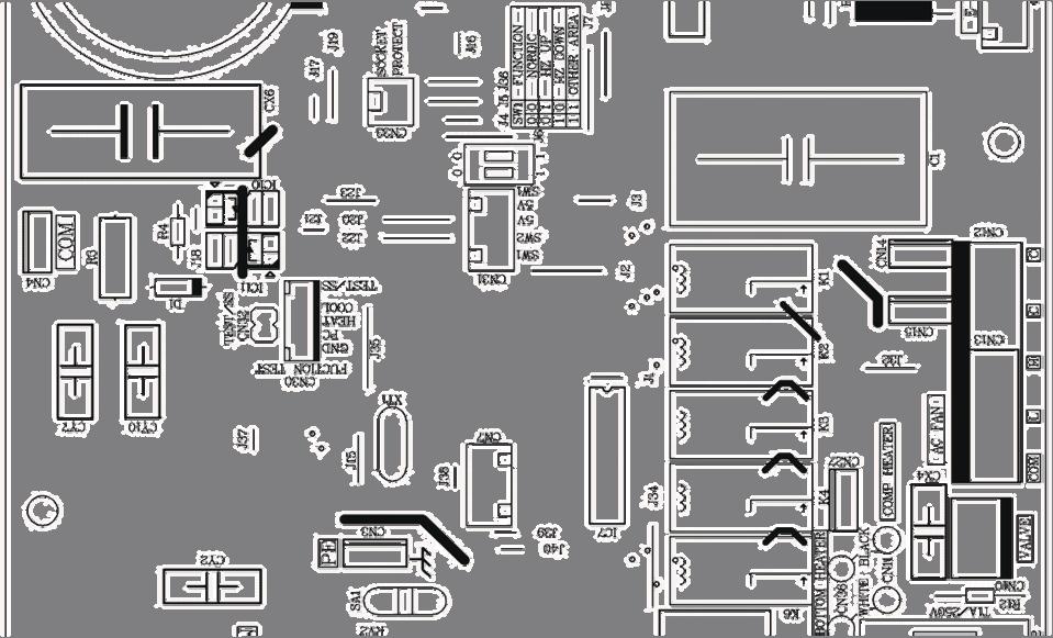
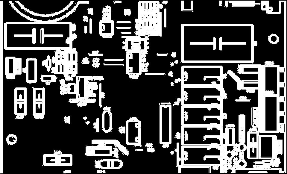
14 AS09/12GS2ERA 1U09/12BS1ERA-SM Connector Wring Diagram 4.2: outdoor unit Connectors PCB(1) (Control PCB) 1) CN1,CN2 Connector for power N and L 2) CN3 Connector for ground 3) CN22 Connector for DC POWER 15Vand 5V to the module board 4) CN9,CN8 Connector for CN2,CN1 on the module board 5) CN13 Connector for fan motor 6) CN10 Connector for four way valve coil 7) CN17,CN18,CN19, CN20 Connector for thermistors 8)CN23 Connector for communicate between the control board and the module board 9) CN26,CN24 Connector to P and N of the module board 10) CN4 Connector for communicate between indoor and outdoor unit 11) CN16 Connector for electric expansion valves Note:09series needn t connect with CN16 and CN18 PCB(2) (module PCB) CN10 Connector for the DC power 5V and 15V form the control PCB CN11 Connector for communicate between the control board and the module board P( CN1), N(CN5) Connector for capacitance board LI (CN7),LO(CN6) Connector for reactor CN2 CN3 CN4 Connector for the U, V, W wire of the compressor Note: Other Designations PCB(1) (Control PCB) 1) FUSE 1, (25A,250VAC) FUSE 2(1A,250VAC) 2)LED 1 keep light representative normal,if keep flash interval representative trouble Alarm 3)RV1,RV2,RV3 Varistor 11 Domestic Air Conditioner
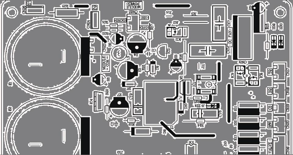
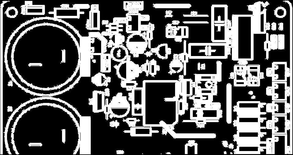
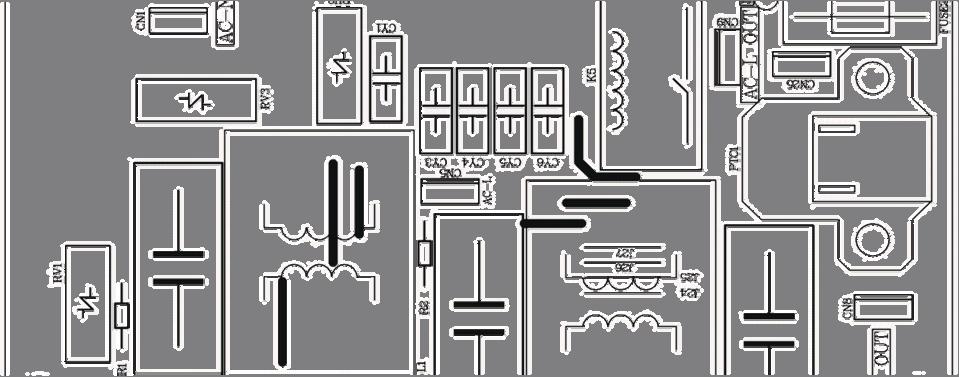
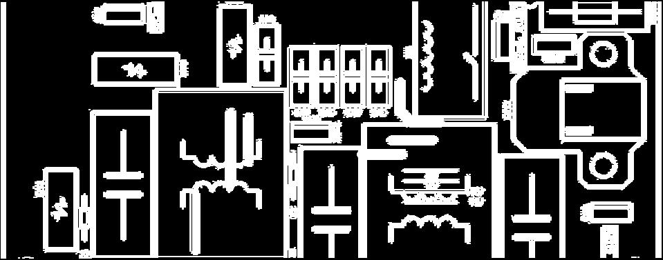
15 AS09/12GS2ERA 1U09/12BS1ERA-SM ConnectorWring Diagram PCB(1) CN26 CN24 CN23 CN22 CN17 CN18 CN19 CN20 CN16 CN4 CN13 CN3 CN1 CN10 CN9 CN8 CN2 CN5 CN6 12 Domestic Air Conditioner
16 AS09/12GS2ERA 1U09/12BS1ERA-SM Connector Wring Diagram PCB(2) CN6 CN7 CN11 CN10 CN5 CN4 CN3 CN2 CN1 13 Domestic Air Conditioner
17 AS09/12GS2ERA 1U09/12BS1ERA-SM Function and control 5.Funcitions and Control 5.1 Main functions and control specification of indoor unit Automatic operation When the running mode is turned to automation after starting the system, the system will first determine the running mode according to the current room temperature and then will run according to the determined mode. Tr in the following selection conditions means room temperature, Ts means setting temperature, Tp means temperature of indoor coil pipe Tr 23 Choose Cooling Mode Tr 23 Choose Heating Mode After turning to the automation mode, the running mode can be switched between cooling mode, fan mode and heating mode according to the change of the indoor ambient temperature. But the automatic conversion between cooling mode and heating mode must be conducted after 15 minutes Cooling operation mode Temperature control range: Temperature difference: 1 * Control features: When Tr input airflow >Ts set temperature, the compressor will be opened,the indoor fan will operate at the set speed and the mode signal will be sent to the outdoor system. When Tr input airflow Ts set temperature, the compressor will be opened,the indoor fan will operate at the set speed and the mode signal will be sent to the outdoor system. The system will keep the original status if Tr= Ts. Airflow speed control: (temperature difference 1 ) Automatic: When Tr>=Ts+3, high speed. When Ts+1 =<Tr<Ts+3, medium speed When Tr<Ts+1, low speed When the sensor is off, low speed When the airflow speed has no delay from the high to low switching, the speed should be delayed for 3 minutes (remain at high speed for 3 minutes.) before the next switch. 14 Domestic Air Conditioner
18 AS09/12GS2ERA 1U09/12BS1ERA-SM Function and control Manus: When the system is operating, you can set the high, medium or low speed manually. ( When the sensor is on or off, the system will change the speed 2 seconds after receiving the signal.) *Airgate location control: the location for the airgate can be set according to your needs. *Defrosting function: preventing the frosting on the indoor heat exchanger (when cooling or demoisture). When the compressor works continuously for 1/6 minutes (adaptable in EEPROM) and the temperature of the indoor coils has been below zero centigrade for 10 seconds, the compressor will be stopped and the malfunction will be recorded in the malfunction list. The indoor system will continue to run. When the temperature of the indoor coil is raised to 7, the compressor will be restarted again (the prerequirement of 3 minutes delay should be satisfied.) * timing system on/off function. * Dormant control function Demoisture mode. * temperature control range: * temperature difference: 1 Control feature: send the demoisture signal to the outdoor system. When Tr>Ts+2, the compressor will be turned on, the indoor fan will operate at the set speed. When Tr is between the Ts and Ts+2, the outdoor system will operate at the high demoisture frequency for 10 minutes and then at the low demoisture mode for six minutes. The indoor fan will operate at low speed. When Tr< Ts, the outsystem will be stopped, the indoor fan will be stopped for 3 minutes and then turned to the low speed option. All the frequency converses have a ±1 difference. * Wind speed control: Automatic: When Tr >= Ts+ 5, high speed. When Ts+3 Tr< Ts+5, medium speed. When Ts+2 Tr< Ts+3, low speed. When Tr<Ts+2, light speed. If the outdoor fan stopped, the indoor fan will be paused for 3 minutes. If the outdoor fan stopped for more than 3 minutes and the outdoor system still operates, the system will be changed into light speed mode. When the airflow speed has no delay from the high to low switching, the speed should be delayed for 3 minutes (remain at high speed for 3 minutes.) before the next switch. Manual: When the sensor is off or Tr< Ts+3, the manual operation can not be made. (obligatory automatic operation.) *Airgate location control: the location for the airgate can be set according to your needs. *Defrosting function: preventing the frosting on the indoor heat exchanger (when cooling or demoisture). When the compressor works continuously for 1/6 minutes (adaptable in EEPROM) and the temperature of the indoor coils has been below zero centigrade for 10 seconds, the compressor will be stopped and the malfunction will be recorded in the malfunction list. The indoor system will continue to run. When the temperature of the indoor coil is raised to 7, the compressor will be restarted again (the prerequirement of 3 minutes delay should be satisfied.) * coil protection (synchronic overheating protection) are installed for the four directions latch malfunctions when demoisturing. * timing system on/off function. 15 Domestic Air Conditioner
19 AS09/12GS2ERA 1U09/12BS1ERA-SM Function and control * Dormant control function Heating operation mode. * temperature control range: * temperature difference: 1 * control feature: the temperature compensation is automatically added and the system will send the heating signals to the outdoor system. If Tr Ts, the outdoor compressor is turned on, the indoor fan will be at the cold air proof mode. If Tr>Ts+3, the outdoor system is turned off, the indoor fan will be at the heat residue sending mode. If Tr<Ts+3 the outdoor system will be turned on again, the indoor fan will be at the cold air proof mode. *Indoor fan control manual control: You can choose high, medium, low and automatic speed control. Automatic: When Tr<Ts, high speed. When Ts=<Tr=<Ts+2, medium speed. When Tr> Ts+2, low speed. When the airflow speed has no delay from the high to low switching, the speed should be delayed for 3 minutes (remain at high speed for 3 minutes.) before the next switch. *Airgate location control: the location for the airgate can be set according to your needs. Coldair proof operation 1. The indoor operation within 4 minutes after the start up is as the following diagram, the air speed can be raised only after the speed has reached a certain level. Set speed Heat start temp 1 Heat start temp 2 Heat start temp 3 Heat start temp 4 Fan/off Fan/off Low speed Light speed Keep the high speed. The fan doesn t stop 2. 4 minutes after the start up of the indoor fan, the light airflow and the low airflow will be turned to the set speed airflow. 3. In the cold air proof operation, the fan won t stop after the start up. 4. During the cold air proof operation, the indoor system will continuously send indoor high speed signals to the outdoor system. * Residue heat sending. The indoor fan will send the residue heat at a low speed for 20 seconds. If other conditions are satisified, when the compressor stops, the indoor system will operate at a light speed. The indoor fan will stop when the coil temperature is below the heat start temp 4. * Defrosting. When the system receives the defrosting signal from outdoors, the indoor fan will stop and the indoor temperature display won t change. At the time, any indoor coil malfunctions will be neglected. When the outdoor defrosting finishes, the coil malfunction will still be neglected until the compressor has been started up for 30 seconds. The indoor temperature display will not change and Domestic Air Conditioner
20 AS09/12GS2ERA 1U09/12BS1ERA-SM Function and control the system operates at the cold air proof mode. * Automatic heating temperature compensation: when the system enters the heating mode, the temperature compensation (4) will be added. When the status is switched off, the compensation will be erased strength operation a. the system enters the mode after receiving the strength signal. Send strength operation signal to the outdoor system. Strength operation quit if you change the fan mode or operation mode. The mode change finishes the strength operation. Entering mute, you can have normal operation or signal control such as timing to finish the strength operation. When the system is at the automatic option,there is no strength/mute function, Mute operation the system enters the mode after receiving the mute signal. a. Mute heating: the airflow speed is slight, the system sends the mute signal to the outdoor system. b. mute cooling: the airflow speed is slight, the system sends the mute signal to the outdoor system. When the compressor operates, the airflow speed is mute speed. EEPROM is adaptable. Mute operation can not work under the demoisturing and airflow-sending operation Air refreshing After receiving the signal from the remote control,(hv series: the background light of the health logo is green. HS series: the health indicator will be lighted). If the fan operates, the negative ion generator operates to realize the negative sending function. If the indoor fan stops, the negative ion generator is turned off. When the negative ion generator is turned off, if the air refreshing system is turned on, the negative ion generator will be turned on when the fan operates Timing. You can set 24 hours on/off timing accordingly. After the setting, the timing indicator will be lightened. Also, the light will be turning off after the timing is finished. The followings are several timing methods. 1.system /on timing: The timing indicator will be lightened and the indoor system is under the waiting mode. The light will be turned off when the timing is finished and the rest of the system will operate under a normal condition. The timing starts since the last reception of the timing singal. You can have the dormacy setting under the timing mode, the order of your settings will be operated according to the timing settings. 2.system /off timing: When the system is turned on, the timing indicator is lightened, the rest of the system will operated under a normal condition. When set time comes, the indicator light will be turned Domestic Air Conditioner
21 AS09/12GS2ERA 1U09/12BS1ERA-SM Function and control off and the system will be turned off. If you have set the dormant functions, the order of your settings will be operated according to the timing settings. The settings will be completed according to the orders Dormant operation The dormant timing is an eight hours unadaptable one. The timing signs are shown on the E series board. (RC series show the dormant signal, the timing light is lighted on the 6 lights board). 2.1 Under the cooling/ demoisture operation, after the setting of the dormant operation, the set temperature will be raised for 1 centigrade after 1 hour s operation and will be raised for 1 centigrade 1 hour later. The system will keep this status for 6 hours and then close. 2.2 Under the heating mode, after the setting of the dormant operation, the et temperature will fall 2 centigrades after 1 hour s operation and will fall 2 centigrades 1 hours later. 3 hours after the preceding operations, the set temperature will be raised for 1 centigrade and the system will keep this status for 3 hours and then close down. 2.3 During the dormant time, except the change of the system mode or a new press on the dormant setting keys, the timing of the 8 hours dormancy will take the first timing as the start time, any presses on other keys will not affect the original timing. 2.4 Indoor fan control under the dormant operation. If the indoor fan is at the high speed before the dormant operation setting, the speed will be turned to medium after the setting. If the fan is at the medium speed before the dormant setting, the speed will be turned to low after the setting. If the fan is at the low speed before the dormant setting, the speed will not change. 18 Domestic Air Conditioner
22 AS09/12GS2ERA 1U09/12BS1ERA-SM Function and control Urgent on/off input Press the urgency button the buzzer will ring. The system will enter the automatic mode if you don t press the button for more than 5 seconds. Under the system off mode, if you press the urgency key for 5 to 10 seconds, the system will start the test operation. Under the system off mode, If you press the urgency key for 10 to 15 seconds, the display screen will show the resume of the last malfunction. If the system is under operation, the press on the urgency key will stop it. Under the system off mode, the display screen will show no sign. Urgency operation: If you press the urgency key for less than 5 seconds, the buzzer will ring when you press the on/off key. The system will enter the urgency operation when the urgency key is loosened. The urgency operation is fully automatic. Test operation. The inlet temperature sensor doesn t work, the indoor fan and the indoor air direction board motor works synchronically. High speed airflow, cooling, outdoor system on, etc, will send the ambient temperature 30 centigrade and coil temperature 16 centigrade information to the outdoor system. Test operation The defrost protection of the evaporator doesn t work. The temperature control doesn t work. The test operation will be finished in 30 minutes. The test operation can be stopped by the relative commands from the remote control Low load protection control In order to prevent the frosting of the indoor heat interaction device, the outdoor system will be stopped if the indoor heat interaction temperature is below zero centigrade for 5 minutes, but the fan will continue to operate. The outdoor system will be started again when the heat interaction temperature is above 7 centigrade and the system has been stopped for 3 minutes. The malfunction will be stored in the malfunction resume and will not be revealed High load protection control The outdoor system will be stopped if the coil temperature is above 65 for 2 minutes. The indoor fan will be controlled by the thermostat. The outdoor system can be restarted when the coil temperature is below 42 and the system has been stopped for 3 minutes. The malfunction will be stored in the malfunction resume and will not be revealed. 19 Domestic Air Conditioner
23 AS09/12GS2ERA 1U09/12BS1ERA-SM Function and control Abnormal operation of indoor system When the outdoor system operates, if the indoor system operation differs from the outdoor system, the abnormal operation malfunction will be reported. 10s after the report, the indoor system will be closed. Outdoor system mode Indoor system mode conflicts cooling heating yes cooling cooling no cooling airflow no heating heating no heating airflow yes heating cooling yes Malfunction list resume. Nothing is presented if there is no code list. The malfunction display will automatically finish in 10 seconds. The remote control only receives the sigals for stop. According to the signals, the malfunction resume presentation finishes. The resume restores after the power supply restores Abnormality confirmation approaches. 1.indoor temperature sensor abnormality: under the operation, the normal temperature ranges from 120 degree to -30 degree. When the temperature goes beyond this range, the abnormality can be confirmed. If the temperature goes back into the range, the system will automatically resume. 2.indoor heat interaction sensor abnormality: under the operation, the normal temperature ranges from 120 degree to -30 degree. When the temperature goes beyond this range, the abnormality can be confirmed. If the temperature goes back into the range, the system will automatically resume. 3.indoor malfunction: Out door malfunction: When the indoor system receives the outdoor malfunction codes, it will store the code into E2 for the malfunction list resume. The indoor system will continue to operate according to the original status, the malfunction code will not be revealed or processed. 4.transmission abnormality: If the indoor system can t receive the outdoor system for 8 minutes, the communication abnormality can be confirmed and reported and the outdoor system will be stopped Single indoor system operation * Enter condition: First, Heating operation mode, set the high speed airflow and 30 centigrade set temperature, then press the dormant keys for 6 times within 7 seconds, the system will feedback with 6 rings. 20 Domestic Air Conditioner
24 AS09/12GS2ERA 1U09/12BS1ERA-SM Function and control * After the system enters the separate indoor system operation mode, the indoor system will operate according to the set mode and neglect the communication signals of the outdoor system. However, it has to send signals to the outdoor system. * Quitting condition: This mode can be quitted after receiving the quitting signal from the remote control or urgency system. The indoor system thus can quit the single operation mode Power cut compensation. * Entering condition: Press dormant button 10 times within 7 second, the buzzer will ring 4 times and the present system status will be stored into the EEPROM of the indoor system. * After entering the power cut compensation mode, the processing of the indoor system should be as the followings: Remote control urgency singal: operate according to the remote control and the urgent conditions, the present status will be stored into the EEPROM of the indoor system. * Quitting conditions: Press dormant button 10 times within 7 seconds and the buzzer will ring twice Fixed frequency operation. 1. Fixed cooling: a. under G code condition: high speed cooling, set 16, press temperature - key and the set key at the same time. The system will enter the fixed frequency operation after the buzzer rings twice. b. The proceeding programs are as the follows: Entering the fixed frequency operation, you can set the fixed strength location 1 and send the coolng signal to the outdoor system. Meanwhile, you can fix the indoor system at high speed mode, the location of the airflow directin board can be switched to the maximal position. c. Quitting condition: The fixed frequency cooling can be quitted after receiving the remote signal, and the system will enter the remote setting status. 2. Fixed heating: a. under G code condition: high speed heating, set 30, press temperature + key and the set key at the same time. The system will enter the fixed frequency operation after the buzzer rings twice. b. The proceeding programs are as the follows: Entering the fixed frequency operation, you can set the fixed strength location 1 and send the heating signal to the outdoor system. Meanwhile, you can fix the indoor system at high speed mode, the location of the airflow directin board can be switched to the maximal position. c. Quitting condition: The fixed frequency heating can be quitted after receiving the remote signal, and the system will enter the remote setting status Time cutting function: connect the test program terminal on the mainboard after connecting the system to the power circuit. The CPU of the main control will be 60 times faster. 21 Domestic Air Conditioner
25 AS09/12GS2ERA 1U09/12BS1ERA-SM Function and control Display function When the system starts up or power on, the background and the LED will be fully lighted for 3 seconds. Then the LED displays the mode you have set Three-color background The multi-color indicator is not lighted when the system is off. The mode-switching will change the indicator colors. Red color is for heating mode, blue for cooling, water color for demoisturing, white for automatic mode, pink for airflow sending, green for health mode and yellow green for air refreshing. The colors health, refreshing colors are preferred to the mode colors. If different status exist at the same time, then the last set color will be shown. The lighting key of the control board can turn on or off the display LED display *Set timing to display timing signs, set dormant mode to display dormant sign.(the dormant signs will be shown on the G series panels.), set health mode to display health sign, set new airflow mode to display new airflow sign and set violet disinfection to display health sign. *Set auto, heating, demoisturing, heating to display the relative signs. When you use a remote control to switch cooling, demoisturing and heating modes, the set temperature will be shown and the screen board will return to the room temperature 5 seconds later. If you choose the airflow sending mode, the screen board will show the room temperature directly. *If the system is under malfunction status, the display will show the malfunction code. Please refer to the malfunction list. 5.2 The control system of outdoor unit The operation frequency of outdoor unit and its control The operation frequency control of compressor The operation frequency scope of compressor Mode Minimun operation frequency Maximun operation frequency Heating 36Hz 90Hz Refrigeration 36Hz 80Hz The starting of compressor When the compressor is started for the first time, it must be kept under the conditions of 58Hz,88Hz for one minute (the overheating protection of the outdoor unit air-blowing temperature, immediately decrease the frequency when the compressor is overflowing and releasing the pressure) then it can be operated towards the target frequency. When the machine runs normally, there s no such process. After starting the compressor for operation, the compressor should run according to the calculated frequency, and every determined frequency for protection should be prior to the calculated frequency The speeds of increasing or decreasing the frequency of the compressor The speed of increasing or decreasing the frequency rapidly HZ/second The speed of increasing or decreasing the frequency slowly HZ/10seconds The calculation of the compressor s frequency 1 The minimum/maximum frequency limitation A While refrigerating: is the maximum operation frequency of the compressor; IN is the minimum operation frequency of the compressor. 22 Domestic Air Conditioner
26 AS09/12GS2ERA 1U09/12BS1ERA-SM Function and control B While heating: is the maximum operation frequency of the compressor; IN is the minimum operation frequency of the compressor. 1 The frequency limitation which is affected by the environment temperature. Heating mode: Serial No. Temperature scope Frequency limitation 1 Wh_c<-12 Max_hz8 90 HZ 2 Wh_c<-8 Max_hz7 90HZ 3 Wh_c<-2 Max_h z4 90HZ 4 Wh_c<5 Max_hz5 90 HZ 5 Wh_c<10 Max_hz1 85 HZ 6 Wh_c<17 Max_hz2 56HZ 7 Wh_c<20 Max_hz6 48HZ 8 Wh_c> 20 Max_hz3 45HZ Remarks: the above are the maximum frequency limitations of the complete appliance which are affected by the environment, and they have nothing to do with the ability of the indoor unit. 23 Domestic Air Conditioner
27 AS09/12GS2ERA 1U09/12BS1ERA-SM Function and control Refrigeration/dehumidification mode: Serial No. Temperature scope Frequency limitation Wh_c<28 Wh_c<32 Wh_c<40 Wh_c<48 Max_hz1 Max_hz2 Max_hz3 Max_hz4 46HZ 80 HZ 72 HZ 65 HZ 5 Wh_c> 48 Max_hz5 50 HZ Remarks: the above are not only the maximum frequency limitations of the complete appliance which are affected by the environment, but also the maximum ability limitation of the system. When the starting ability is not the maximum, its maximum frequency limitation is calculated by the following equations: The frequency limitation which is affected by the temperature and under the condition of actual ability the actural running system ability*the maximum frequency which is limited by the temperature and under the condition of maximum ability/the maximum designing ability of the system T= Ti*Pi / Pi ( Ti= Tst_i-Tnh_i the indoor environment temperature ;Pi i the ability of the indoor unit) Refrigeration/dehumidification: The percentage of the rated frequency P Heating mode T < >=4 50% 70% 100% 120% 140% T < >=4 The percentage of the rated frequency P 50% 70% 100% 140% 140% K= Ki/the number of running machines The indoor set airflow speed The percentage of the rated frequency Ki Breeze Low Medium High Strong Quiet Healthy airflow 70 70% 90% 100% 120% 70% 70% The calculation of the actual output frequency: when there is no healthy airflow: F =F-ED-* P K When the healthy airflow has been set: F =F-ED-* P K airflow speed K healthy airflow When refrigerating, it is needed to satisfy IN < F< When heating, it is needed to satisfy IN r< F< r 5.2.2: The outdoor fan control (exchange fan) When the fan is changed among every airflow speed (including stop blowing), in order to avoid the airflow speed from skipping frequently, it must be kept under each mode for over 30 seconds, and then it can be changed to another mode (when refrigerating, the time is changed to 15 seconds) :The outdoor fan control when refrigerating or dehumidifying After the compressor is started for 5 seconds, the outdoor fan is started at the medium speed at first, 24 Domestic Air Conditioner
28 AS09/12GS2ERA 1U09/12BS1ERA-SM Function and control after 30 seconds,it begins to control the airflow speed according to the temperature conditions of the outdoor environment. The temperature of the outdoor air Ta The temperature of the outdoor coil Te Ta 30 High Airflow speed 26 Ta<30 Keeping the speed 24 Ta<26 Medium 23 Ta<24 Keeping the speed 5 Ta<23 Low Ta<5 15 Te Low 15 >Te Stop :The outdoor fan control when heating The temperature of the outdoor air Ta Ta 22 Low Airflow speed 19 Ta<22 Keeping the speed 16 Ta<22 Medium 14 Ta<16 Keeping the speed Ta<14 High The control of the outdoor electronic expansion valve When starting the compressor: the opening size of the valve must be guaranteed to have entered into the standard opening size, and then the compressor can be started. When refrigeration is in vain (the machine is shut down or is in the state of retrograde operation), the opening size of the expansion valve of the indoor unit is 5 steps; When heating is in vain, the opening size of the expansion valve of the indoor unit is 55 steps; When the outdoor unit is shut down, the valve is opened completely for 2 minutes, and then begin initialization. The scope of refrigerationg valve steps The scope of heating valve steps The valves are adjusted according to the degree of superheat SHa SHa Four way control For the details of defrosting four-way valve control, see the defrosting process. Four way working in other ways: Under the mode of heating, open the four-way valve, when the compressor is not started or changed to non-heating mode, make sure the compressor is stoped for 2 minutes, and then close the four-way valve. 25 Domestic Air Conditioner
29 AS09/12GS2ERA 1U09/12BS1ERA-SM Function and control The outdoor defrosting control A.The conditions for entering into defrosting mode When starting running heating, the compressor continuously runs for over 10 minutes, after running for 45 minutes in all (defrosting is ended or when entering into refrigeration mode, clear the compressor s cumulative run time), through detecting the defrosting sensor TCS detect the defrosting situation of the heat exchanger of the outdoor unit and the outdoor environment temperature sensor TA, and meeting the following conditions continuously for 2 minutes, the machine enters into the defrosting operation: TCS C TA is determined as the following according to the data of EEPROM: C selcet if Tao 0 C=0.8;if Tao 0 C=0.6 is read from EEPROM Normal State: =6 The temperature limitation for entering into defrosting mode -15 C TA -5 B.Defrosting time interval When the result of C TA is in the scope of -15 C TA, the interval between two defrostings is 45 minutes (the time interval which is in 57 digits in EEPROM can be adjusted When the result of C TA is in the scope of C TA <-15, the time interval between two defrostings is 65 minutes. C.Defrosting operation When starting defrosting, the compressor stops for 1 minute at first, and the outdoor fan is running, after 55 seconds, the four-way valve is off. When the compressor is started, the outdoor fan is stoped, the compressor stops for 30 seconds at the conditions of 58HZ, and then runs towards the target frequency 88HZ. During defrosting period, the protections, such as current of the compressor, compressor s blowing and so on, are in effect. During defrosting period, the compressor which is stoped because of protection or malfunction will reinstate after stoping for 3 minutes, and don t clear the cumulated run time. When it is satisfied with the continuously running time, it will enter into the defrosting mode. After entering into defrosting mode, make sure the compressor runs for at least for 2 minutes, and then it can withdraw from defrosting. If a single machine causes defrosting, the other machines all involve in defrosting. D.The conditions of withdrawing from defrosting The defrosting operation will change to heating operation, if any of the following conditions is satisfied: 1 The temperature of the outdoor heat exchanger is continuously over 7 for 80 seconds. 2 The temperature of the outdoor heat exchanger is continuously over 12 for5seconds. 3 Continuously run defrosting for 11 minutes 56 digits in EEPROM can be adjusted. E When satisfying the conditions of withdrawing from defrosting, the machine works as the followings: The compressor stops, the outdoor fan is started, and the four-way valve is closed, after 60 seconds the compressor runs according to the starting process Protection function TTC high temperature-preventing protection Once the machine is started, it can run TTC overheating protection of air-blowing, but air-blowing sensor malfunction must alarm after 4 minutes during which the compressor is started (during the Domestic Air Conditioner
30 Remarks: the outdoor unit AS09/12GS2ERA 1U09/12BS1ERA-SM Function and control The control of preventing the overcurrent of the compressor During the starting process of the compressor, if the curren of the compressor is greater than 11A for 3 seconds, stop the compressor and alarm, after 3 minutes, start it again, if such state appears 3 times in 20 minutes, stop the compressor and alarm, and confirm the malfunction. Then continue to run it only after the the power is off. During the starting process of the compressor, if the AC current is greater than 8.5A, the frequency of the compressor decreases at the speed of 1HZ/second. During the starting process of the compressor, if the AC current is greater than 8A, the frequency of the compressor decreases at the speed of 0.1HZ/second. During the starting process of the compressor, if the AC current is greater than 7A, the frequency of the compressor increases at the prohibited speed. During the starting process of the compressor, if the AC current is greater than 6.5A, the frequency of the compressor increases at the speed of no faster than 0.1HZ/second The protection function of AC current: During the starting process of the compressor, if the AC current is greater than 9A, the frequency of the compressor decreases at the speed of 1HZ/second. During the starting process of the compressor, if the AC current is greater than 8A, the frequency of the compressor decreases at the speed of 0.1HZ/second. During the starting process of the compressor, if the AC current is greater than 7A, the frequency of the compressor increases at the prohibited speed. During the starting process of the compressor, if the AC current is greater than 6.5A, the frequency of the compressor increases at the speed of no faster than 0.1HZ/second. Remarks: when the outdoor temperature is high, there s compensation for AC current protection. When the outdoor environment temperature is higher than 40, AC current protection value decreases by 1.0A When the outdoor environment temperature is higher than 50,AC current protection value decreases by 3.0A Antifreezing protection of the indoor heat exchanger When refrigerating/heating, prevent freezing. Tpg_indoor is the minimum value of the effective indoor unit (start it and it is in accord with the running state). 28 Domestic Air Conditioner
31 AS09/12GS2ERA 1U09/12BS1ERA-SM Function and control course of self-detection, there s no such limitation) Sensor detection methods: 100 times (one cycle of procedure run is one time, and about 5ms, detection method for each time: continuously sampling for 8 times, then order them and take the mean value of the middle 2 values), take the mean value. TTC 110 Abnormal stop Decreasing the frequency rapidly 1HZ/second 100 Decreasing the frequency slowly (1HZ/10seconds) The frequency doesn t change. 90 Increasing the frequency (1HZ/10second) Increasing the frequency 1HZ/1second TTC>=110 lasts for 20 seconds. Overheating protection of air-blowing, alarm malfunction to the indoor, others don t last TC high temperature-preventing control of the indoor heating unit Tpg_indoor is the highest value of the effective indoor unit (start it and it is in accord with the running state). The indoor heat exchanger sensor tests the temperature of the indoor heat exchanger. If the temperature is higher than 55, decrease the rotate speed of the compressor and do the high temperature-preventing protection of the indoor heat exchanger; if the temperature of the indoor heat exchanger is lower than 47, recover to the normal control. TC Thecompressorstops Fgh_t1 2 Fgh_t1 65 N Decreasing the frequency rapidly Fgh_t2 59 Fgh_t2 2 P Decreasing the frequency slowly Fgh_t3 54 Fgh_t3 2 Q Prohibiting increasing the frequency Fgh_t4 51 Fgh_t4 2 R Increasing slowly Fgh_t5 47 Fgh_t5 2 Normal N Decreasing at the speed of 1HZ/1 second P Decreasing at the speed of 1Hz/10 seconds Q Continue to keep the last-time instruction cycle R Increasing at the speed of 1Hz/10seconds Domestic Air Conditioner
32 AS09/12GS2ERA 1U09/12BS1ERA-SM Function and control 12 //ice_temp_4+2 ice_temp_4 9 Increasing slowly 8 //ice_temp_3+2 Keeping the frequency ice_temp_3 7 ice_temp_2 5 Decreasingslowly ice_temp_1 3 Decreasing rapidly ice_temp_1 0 Stop When Tpg_indoor ice_temp_1, the frequency of the compressor decreases at the speed of 1HZ/1second. When Tpg_indoor ice_temp_2, the frequency of the compressor decreases at the speed of 1HZ/10seconds. When Tpg_indoor begins to rise again, and ice_temp_2 =Tpg_indoor = ice_temp_3, the frequency of thecompressor doesn t change. When ice_temp_3 Tpg_indoor ice_temp_3+3, the frequency of the compressor increases at the speed of 1HZ/10seconds. For example, Tpg_indoor<= 0 last for 2 minutes, and then the outdoor unit will stop, and report underload malfunction, but don t send malfunction report to the indoor. The compressor stops for more than 3 minutes, Tpg_indoor> ice_temp_3+2, the compressor recovers The frequency limitation of modification rate In the field which is controlled by high frequency, if the modification rate is not high enough, the control-driven on chip will enter into weak magnetic control, this will help to relieve the problem of modification rate. If during the course of weak magnetic control, the modification rate is still not high enough, enter into the control of decreasing frequency until the alarm of modification rate is relieved Temperature protection of the outdoor refrigerating coil When the defrosting temperature and the sensor s temperature are higher than 65, the frequency of the compressor decreases 1hz/10seconds. Keep the frequency until it decreases to the lowest frequency. When the temperatures are lower than 65 and higher than 60, keep the frequency of the compressor. When the temperatures are lower than 60, relieve the defrosting temperature protection Malfunction display and malfunction handling a) For the complete appliance s malfunctions Annex 2 If there s malfunction with the outdoor unit, the light of the outdoor unit will flash and its frequency is 1HZ, the number of times is according to the table, when a round of flashing is finished, the light shoud be off for 5 seconds. b) For the units malfunctins Annex 1 If there s malfunction with the units, this will not affect the run of the complete appliance, but this can be displayed by the malfunction light, the light flashing frequency is 0.5HZ, the number of times is according to the malfunction table of the indoor units. When a round of flashing is finished, the light shoud be off for 10 seconds. Then report according to the order : unit A unit B unit C unit D, that Domestic Air Conditioner
33 AS09/12GS2ERA 1U09/12BS1ERA-SM Function and control is, if there s malfunction with several units, then just report the indoor unit with the highest priority level. Among the unit malfunctions, the priority level of the communication malfunction is the highest, for others, that appears first will have the priority. Remarks: in 3 minutes when the compressor stops, the units malfunctions are not displayed; the complete appliance s malfunctions are prior to the units malfunctions. Annex 1 Malfunction codes of the whole unit Remarks: under the mode of refrigeration, the malfunctions of each unit s thin pipe temperature sensor are not reported, under the mode of heating, the malfunctions of each unit s thick pipe temperature sensor are not reported. 5.3 Value of Thermistor intdoor Unit R25 =10K ±3% B25 /50 =3700K±3% Room sensor and Pipe Sensor Temp.(( )) Max.(K ) Normal(K ) Min.(K ) Tolerance( ) Domestic Air Conditioner
34 AS09/12GS2ERA 1U09/12BS1ERA-SM Function and control Domestic Air Conditioner
35 AS09/12GS2ERA 1U09/12BS1ERA-SM Function and control Domestic Air Conditioner
36 AS09/12GS2ERA 1U09/12BS1ERA-SM Function and control Outdoor Unit Ambient Sensor, Defrosting Sensor, Pipe sensor R25 =10K ±3% B25 /50 =3700K±3% Temp.( ) Max.(K ) Normal(K ) Min.(K ) Tolerance( ) Domestic Air Conditioner
37 AS09/12GS2ERA 1U09/12BS1ERA-SM Function and control Domestic Air Conditioner
38 AS09/12GS2ERA 1U09/12BS1ERA-SM Function and control Domestic Air Conditioner
39 AS09/12GS2ERA 1U09/12BS1ERA-SM Function and control Domestic Air Conditioner
40 AS09/12GS2ERA 1U09/12BS1ERA-SM Function and control R80 =50K ±3% B25/80 =4450K±3% Discharging Sensor Temp.(( )) Max.(K ) Normal(K ) Min.(K ) Tolerance( ) Domestic Air Conditioner
41 AS09/12GS2ERA 1U09/12BS1ERA-SM Function and control Domestic Air Conditioner
42 AS09/12GS2ERA 1U09/12BS1ERA-SM Function and control Domestic Air Conditioner
43 AS09/12GS2ERA 1U09/12BS1ERA-SM Function and control Domestic Air Conditioner
44 AS09/12GS2ERA 1U09/12BS1ERA-SM 41
45 Outdoor Unit 4 AS09/12GS ERA 1U09/12BS1ERA-SM Parts and Functions Indoor Unit Inlet grille Outlet Vertical blade Emergency (adjust left and right air flow) Switch Horizontal flap (adjust up and down air flow Display board Don't adjust it manually) Please be subject to the actual produce purchased the above picture is just from your reference OUTLET INLET Inlet CONNECTING PIPING AND ELECTRICAL WIRING DRAIN HOSE Air Purifying Filter (inside) Display board Signal receiver hole 4 TIMER ON\OFF display 2 ON/OFF display TIMER ON-OFF display SLEEP display 3 Ambient temp.display Note to the power failure resume: When receiving the remote press the sleep button ten times in five seconds control signal, display the set and enter function after hearing four sounds.and temperature and in the rest press the sleep button ten times within five seconds and leave this function after hearing time the room temperature is two sounds. displayed and this room temperature is only for reference. 5 COOL\HEAT\Dry\AUTO display Please be subject to the actual produce purchased the above picture is just from your reference Remote controller 1. Mode display Operation mode AUTO COOL DRY HEAT FAN Remote controller 2. Signal sending display 3. SWING display 4. FAN SPEED display LO MED HI 5. LOCK display 6. TIMER OFF display TIMER ON display 7.TEMP display Display circulated AUTO Loading of the battery Introduction 8. Additional functions display Healthy function is not available for some units. Operation mode QUITE SLEEP Supplemented electrical heating HEALTH POWER Remote controller 9. QUIET button 10. HEAT button 11. COOL button 12. AUTO button 13. FAN button 14. TIMER button 15. HEALTH button 16. LOCK button Used to lock buttons and LCD display. 17. LIGHT button Control the lightening and extinguishing of the indoor LED display board. 18. POWER ON/OFF button 19. DRY button 20. TEMP button 21. SWING button 22. HOUR button 23. EXTRA FUNCTION button Function: Air sending--- Healthy airflow position1--- Healthy airflow position Restore the original flap position --- Right & left air airflow--- A-B yard and heating symbol displayed simultaneously--- Sleeping--- Electrical heating--- Refresh air(reserved function) --- Power--- Fahrenheit/Celsius mode conversion 24.CANCEL/CONFIRM button Function: Setting and cancel to the timer and other additional functions. 25. RESET button When the remote controller appears abnormal, use a sharp pointed article to press this button to reset the remote Remove the battery cover; Load the batteries as illustrated. 2 R-03 batteries, resetting key (cylinder); 3 Be sure that the loading is in line with the" + "/"-"; 4 Load the battery,then put on the cover again. Note: The distance between the signal transmission head and the receiver hole should be within 7m without any obstacle as well. When electronic-started type fluorescent lamp or change- over type fluorescent lamp or wireless telephone is installed in the room, the receiver is apt to be disturbed in receiving the signals, so the distance to the indoor unit should be shorter. Full display or unclear display during operation indicates the batteries have been used up. Please change batteries. If the remote controller can't run normally during operation, please remove the batteries and reload several minutes later. Hint: Remove the batteries in case won't be in use for a long period. If there is any display after taking-out, just press reset key. 42 Domestic air conditioner
46 Operation Base Operation Remote controller 3 AS09/12GS ERA 1U09/12BS1ERA-SM Introduction Emergency operation and test operation Emergency Operation: Use this operation only when the remote controller is defective or lost, and with function of emergency running, air conditoner can run automatically for a while. When the emergency operation switch is pressed, the " Pi " sound is heard once, which means the start of this operation. When power switch is turning on for the first time and emergency operation starts, the unit will run automatically in the following modes: Room temperature Designated Timer temperature mode Fan Operation speed mode Pi 1. Unit start Press ON/OFF on the remote controller, unit starts. 2. Select operation mode COOL button:cooling mode HEAT button: Heating mode DRY button: Dehumidify mode 3.Select temp.setting Press / button Every time the button is pressed, temp.setting increase 1 o C,if kept depressed, it will increase rapidly Every time the button is pressed, temp.setting decrease 1 o C,if kept depressed, it will decrease rapidly Select a desired temperature. 4.Fan speed selection Press FAN button. For each press, fan speed changes as follows: Remote controller: Display circulated LOW MED HI AUTO Air conditioner is running under displayed fan speed. When FAN is set to AUTO, the air conditioner automatically adjusts the fan speed according to room temperature. Above 23 o C 26 o C Below 23 o C 23 o C Air Flow Direction Adjustment 1.Status display of air flow No No AUTO AUTO COOL HEAT It is impossible to change the settings of temp. and fan speed,it is also not possible to operate in timer or dry mode. Test operation: Test operation switch is the same as emergency switch. Use this switch in the test operation when the room temperature is below 16 o C, do not use it in the normal operation. Pi Pi Continue to press the test operation switch for more than 5 seconds. After you hear the "Pi" sound twice, release your finger from the switch: the cooling operation starts with the air flow speed "Hi". Under this operation mode,the fan motor of indoor unit will run in high speed. COOL/DRY: HEAT: Initial state 2.Left and right air flow adjustment(manual) Move the vertical blade by a knob on air conditioner to adjust left and right direction referring to Fig. Operation Mode AUTO COOL DRY HEAT FAN Remote Controller Note Under the mode of auto operation, air conditioner will automatically select Cool or Heat operation according to room temperature. When FAN is set to AUTO the air conditioner automatically adjusts the fan speed according to room temperature. In DRY mode, when room temperature becomes lower than temp.setting+2 o C, unit will run intermittently at LOW speed regardless of FAN setting. In HEAT mode, warm air will blow out after a short period of the time due to cold-draft prevention function. When FAN is set to AUTO, the air conditioner automatically adjusts the fan speed according to room temperature. In FAN operation mode, the unit will not operate in COOL or HEAT mode but only in FAN mode, AUTO is not available in FAN mode. And temp. setting is disabled. In FAN mode, sleep operation is not available. 43 3D Cautions: When adjusting the flap by hand,turn off the unit. When humidity is high,condensate water might occur at air outlet if all vertical louvers are adjusted to left or right. It is advisable not to keep horizontal flap at downward position for a long time in COOLor DRY mode, otherwise, condensate water might occur. Note: When restart after remote turning off, the remote controller will automatically memorize the previous set swing position. Domestic air conditioner

47 Operation Sleep Operation Press button to enter additional options, when cycle display to, will flash. And then press enter to sleep function. AS09/12GS ERA 1U09/12BS1ERA-SM Introduction 4. In FAN mode It has no SLEEP function. 5.Set the wind speed change when sleeping If the wind speed is high or middle before setting for the sleep, set for lowing the wind speed after sleeping. If it is low wind, no change. Note When TIMER function is set, the sleeping function can t be set up.after the sleeping function is set up, if user resets TIMER function, the sleeping function will be cancelled; the machine will be in the state of timing-on. POWER/QUIET Operation Operation Mode 1. In COOL,DRY mode 1 hours after SLEEP mode starts,temp.will become 1 O C higher than temp.setting.after another 1 hours,temp.rises by 1 O C futher.the unit will run for further 6 hours then stops Temp. is higher than temp.setting so that room temperature won t be too low for your sleep. SLEEP operation starts 1 hr Temp.setting 1 hr Rises 1 O C SLEEP operation stops Approx.6hrs Rises 1 O C In COOL, DRY mode Unit stop 2. In HEAT mode 1 hours after SLEEP mode starts,temp will become 2 O C lower than temp.setting.after another 1 hours,temp decrease by 2 O C futher.after more another 3 hours,temp. rises by 1 O C futher.the unit will run for further 3 hours then stops.temp.is lower than temp. setting so that room temperature won t be too high for your sleep. (1) POWER Operation When you need rapid heating or cooling, you can use this function. Press button to enter additional options, when cycle display to, will flash and then press,enter to power function. When cancel the function, please enter additional options again and to cancel power function. (2) QUIET Operation You can use this function when silence is needed for rest or reading. Press QUIET button, the remote controller will show, and then achieve to the quiet function. Press again this QUIET button, the quiet function will be cancelled. Note During POWER operation, in rapid HEAT or COOL mode, the room will show inhomogeneous temperature distribution. Long period QUIET operation will cause effect of not too cool or not too warm. Temp.setting Unit stop 1 hr Decreases 2 O C 1 hr Decreases 2 O C SLEEP operation starts 4 3 hrs In HEAT mode 3 hrs Rises 1 O C SLEEP operation stops 3. In AUTO mode The unit operaters in corresponding sleep mode adapted to the automatically selected operation mode. 44 Domestic air conditioner
48 Operation AS09/12GS ERA 1U09/12BS1ERA-SM Timer On/Off On-Off Operation 1.After unit starts, select your desired operation mode. 2.Press TIMER button to change TIMER mode. Every time the button is pressed, display changes as follows: Remote controller: 0.5h 0.5h 0.5h 0.5h TIMER ON TIMER OFF TIMER ON-OFF TIMER OFF-ON BLANK Then select your desired TIMER mode (TIMER ON or TIMER OFF or TIMER ON-OFF). " "or " "will flash. 3.Press / button to set time. Press the button for each time, setting time in the first 12 hours increased by 0.5 hour every time, after 12 hours,increased by 1 hour every time. Press the button for each time, settiing time in the first 12 hours decreased by 0.5 hour every time, after 12 hours,decreased by 1 hour every time. It can be adjusted within 24 hours. 4.Confirm timer setting After adjust the time,press button and confirm the time ON or OFF button will not flash any more. 5.Cancel timer setting Press the timer button by times until the time display eliminated. Hints: After replacing batteries or a power failure happens, time setting should be reset. According to the Time setting sequence of TIMER ON or TIMER OFF, either Start-Stop or Stop-Start can be achieved. Healthy airflow Operation 1.Press to starting Setting the comfort work conditions. 2.The setting of healthy airflow function Press button to enter additional options,press this button continuously, the louvers location will cycle between in the following three locations, to choose the swing location what you needed,and then press button to confirm. Healthy airflow upwarder Healthy airflow downwarder Present position 3.The cancel of the healthy airflow function Press button to enter additional options,press this button continuously, the louvers location will cycle between in the following three locations again,and then press button to cancel. Notice: Do not direct the flap by hand. Otherwise, the grille will run incorrectly. If the grille is not run correctly, stop for a minute and then start, adjusting by remote controller. Note: 1.After setting the healthy airflow function, the position grill is fixed. 2.In heating, it is better to select the mode. 3.In cooling, it is better to select the mode. 4.In cooling and dry, using the air conditioner for a long time under the high air humidity, condensate water may occur at the grille. 45 Introduction EUROPEAN REGULATIONS CONFORMITY FOR THE MODELS CE All the products are in conformity with the following European provision: - Low Voltage Directive 73/23/EEC - Low Voltage Directive 2006/95/EC -Electomagnetic CompatibilitY 89/336/EEC -Electomagnetic CompatibilitY 2004/108/EC ROHS The products are fulfilled with the requirements in the directive 2002/95/EEC of the European parliament and of council on the Restriction of the use of Certain Hazardous Substances in Electrical and Electronic Equipment (EU RoHS Directive) WEEE In accordance with the directive 2002/96/CE of the European parliament, herewith we inform the consumer about the disposal requirements of the electrical and electronic products. DISPOSAL REQUIREMENTS: Your air conditioning product is marked with this symbol.this means that electrical and electronic products shall not be mixed with unsorted household waste. Do not try to dismantle the system yourself : the dismantling of the air conditioning system,treatment of the refrigerant, of oil and of other part must be done by a qualified installer in accordance with relevant local and national legislation. Air conditioners must be treated at a specialized treatment facility for reuse, recycling and recovery. By ensuring this product is disposed of correctly, you will help to prevent potential negative consequences for the environment and humen health. Please contact the installer or local authority for more information. Battery must be removed from the remote controller and disposed of separately in accordance with relevant local and nationl legislation. IMPORTANT INFORMATION REGA- RDING THE REFRIGERANT USED Contains fluorinated greenhouse gases covered by the Kyoto Protocol 1= kg R410A 2 2= kg 1 1+2= kg F E This product contains fluorinated greenhouse gases covered by the Kyoto Protocol. Do not vent into the atmosphere. Refrigerant type:r410a GWP* value:1975 GWP=global warming potential Please fill in with indelible ink, 1 the factory refrigerant charge of the product 2 the additional refrigerant amount charged in the field and 1+2 the total refrigerant charge on the refrigerant charge label supplied with the product. The filled out label must be adhered in the proximity of the product charging port (e.g. onto the inside of the stop value cover). A contains fluorinated greenhouse gases covered by the Kyoto Protocol B factory refrigerant charge of the product: see unit name plate C additional refrigerant amount charged in the field D total refrigerant charge E outdoor unit F refrigerant cylinder and manifold for charging A B C D Domestic air conditioner
49 AS09/12GS ERA 1U09/12BS1ERA-SM Indoor Unit Installaion Introduction Necessary Tools for Installation Driver Torque wrench Nipper (17mm,22mm,26mm) Hacksaw Pipe cutter Hole core drill Flaring tool Spanner(17,19 and 26mm) Knife Gas leakage detector or Measuring tape soap-and-water solution Reamer Selection of Installation Place Power Source Before inserting power into receptacle, check the voltage without fail. The power supply is the same as the corresponding nameplate. Install an exclusive branch circuit of the power. A receptacle shall be set up in a distance where the power cable can be reached.donotextendthecablebycuttingit. Accessory Parts Place, robust not causing vibration, where the body can be supported sufficiently. Place, not affected by heat or steam generated in the vicinity, where inlet and outlet of the unit are not disturbed. Place, possible to drain easily, where piping can be connected with the outdoor unit. Place,wherecoldaircanbespreadin a roomentirely. Place, nearby a power receptacle, with enough space around. Place where the distance of more than lm from televisions, radios, wireless apparatuses and fluorescent lamps can be left. In the case of fixing the remote controller on a wall, place where the indoor unit can receive signals when the fluorescent lamps in the room are lightened. Remote controller (1) R-03 dry battery (2) Mounting plate (1) FOR 07K 09K 12K FOR 18K FOR 24K Drain hose (1) Plastic cap (4) Ø4X25 Screw (4) Air purifying filter(optional) (1) Selection of Pipe ThemodelsadoptHFCfreerefrigerantR410A Drawing for the installation of indoor units more than 15cm Attention must be paid to the rising up of drain hose Arrangement of piping directions more than 10cm Left Rear left Rear right Right Below more than 10cm The distance between the indoor unit and the floor should be more than 2m. Please be subject to the actual product purchased,the above picture is just for your reference. 46 Domestic air conditioner
50 AS09/12GS ERA 1U09/12BS1ERA-SM Indoor Unit Installation 1 Fitting of the Mounting Plate and Positioning of the wall Hole When the mounting plate is first fixed 1. Carry out, based on the neighboring pillars or lintels, a proper leveling for the plate to be fixed against the wall, then temporarily fasten the plate with one steel nail. 2. Make sure once more the proper level of the plate, by hanging a thread with a weight from the central top of the plate, then fasten securely the plate with the attachment steel nail. 3. Find the wall hole location A using a measuring tape [Left Left-rear piping ] Introduction In case of left side piping, cut away, with a nipper, the lid for left piping. Incase of left-rearpiping,bendthepipesaccordingtothepiping direction to the mark of hole for left-rear piping which is marked on heat insulation materials. 1. Insert the drain hose into the dent of heat insulation materials of indoor unit. 2. Insert the indoor/outdoor electric cable from backside of indoor unit,and pull it out on the front side, then connect them. 3.Coattheflaringsealfacewithrefrigerantoilandconnect pipes. Cover the connection part with heat insulation materials closely, and make sure fixing with adhesive tape Indoor/outdoor electric cable B= Ø70mm Lid for right piping Lid for under piping pipe Lid for left piping Heat insulation material Drain hose Piping Pipe supporting plate A=145mm A=150mm 30mm B= 70mm B= Ø70mm 35mm Fix with adhesive tape Indoor/outdoor electric cable and drain hose must be bound with efrigerant piping by protecting tape. [ Other direction piping ] Cut away, with a nipper, the lid for piping according to the piping direction and then bend the pipe according to theposition of wall hole. When bending, be careful not to crash pipes. Connectbeforehandtheindoor/outdoorelectriccable, and then pull out the connected to the heat insulation of connecting part specially. Fixing the indoor unit body A=145mm When the mounting plate is fixed side bar and lintel Fix to side bar and lintel a mounting bar, Which is separately sold, and then fasten the plate to the fixed mounting bar. Refer to the previous article, When the mounting plate is first fixed, for the position of wall hole. 2 Making a Hole on the Wall and Fitting the Piping Hole Cover 30mm Hang surely the unit body onto the upper notches of the mountingplate.movethebody from side to side to verify its secure fixing. Inordertofixthebodyontothemounting plate,hold up the body aslant from the underside and thenputitdownperpendicularly. Unloading of indoor unit body mounting plate When you unload the indoor unit,please use your hand to arise the body to leave agraffe,then lift the bottom of the body outward slightly and lift the unit aslant until it leaves the mounting plate. Make a hole of 70 mm in diameter, slightly descending to outside the wall Install piping hole cover and seal it off with putty after installation Wall hole Ø70mm agraffe mounting plate Indoor side 3 Installation of the Indoor Unit Thickness of wall (Section of wall hole) G Piping hole pipe Drawingofpipe Outdoor side [Rearpiping] Drawpipesandthedrainhose,thenfastenthemwiththeadhesivetape 47 4 Connecting the indoor/outdoor Electric Cable Removing the wiring cover Remove terminal cover at right bottom corner of indoorunit,thentake off wiring cover by removing its screws. Domestic air conditioner
51 AS09/12GS ERA 1U09/12BS1ERA-SM Introduction When connecting the cable after installing the indoor unit Correct Incorrect 1. Insert from outside the room cable into left side of the wall hole, in which the pipe has already existed. 2.Pulloutthecableonthefrontside,andconnectthecable making a loop. When connecting the cable before installing the indoor unit Insertthecablefromtheback side of the unit, then pull it out on the front side. Loosen the screws and insert the cable ends fully into terminal block, then tighten the screws. Pull the cable slightly to make sure the cables have been properly inserted and tightened. After the cable connection, never fail to fasten the connected cable with the wiring cover. Note: To Outdoor unit When connecting the cable, confirm the terminal number of indoor and outdoor units carefully. If wiring is not correct, proper operation can not becarriedoutandwillcausedefect. Model AS07GS2ERA AS09GS2ERA AS12GS2ERA AS18GS2ERA AS24GS2ERA Connecting wiring 4G0.75mm 2 4G0.75mm 2 4G0.75mm 2 1.Ifthesupplycordisdamaged,itmustbereplacedbythemanufacturerorits service agent or a similar qualified person. The type of connecting wire is H05RN-F or H07RN-F. 2. If the fuse on PC board is broken please change it with the type of T.3.15A/250VAC (Indoor). 3.Thewiringmethodshouldbeinlinewiththelocalwiringstandard. 4. After installation, the power plug should be easily reached. 5. A breaker should be incorporated into fixed wiring. The breaker should be all-pole switch and the distance between its two contacts should be not less than 3mm. PowerSourceInstallation The power source must be exclusively used for air conditioner. In the case of installing an air conditioner in a moist place, please install an earth leakage breaker. For installation in other places, use a circuit breaker as far as possible. CuttingandFlaringWorkofPiping Indoor unit Pipe cutting is carried out with a pipe cutter and burs must be removed. After inserting the flare nut, flaring work is carried out. FlaretoolforR410A Conventionalflaretool Clutch-type clutch-type(rigid-type) Wing-nut type (Imperial-type) A 0~0.5mm 1.0~1.5mm 1.5~2.0mm Flare tooling die 1.Cut pipe 3.Insert the flare nut 2.Remove burs 4.Flare pipe It becomes high midway. On Drainage Lean Damage of flare Crack Partial Too outside Pleaseinstallthedrainhosesoastobedownwardslopewithoutfail. Please don t do the drainage as shown below. The end is immersed in water. Less than 5cm It waves. The gap with the There is the bad ground is too small. smell from a ditch Please pour water in the drain pan of the indoor unit, and confirm that drainage is carried out surely to outdoor. In case that the attached drain hose is in a room, please apply heat insulation to it without fail. On Drainage Code Trouble description Analyze and diagnose indication E1 E2 E4 E7 E14 Indoor fan motor malfunction Heat-exchange sensor failure Indoor EEPROM error Communication fault between indoor and outdoor units Indoor fan motor malfunction Faulty connector connection; Faulty thermistor; Faulty PCB; Faulty EEPROM data; Faulty EEPROM; Faulty PCB; Indoor unit- outdoor unit signal transmission error due to wiring error; Faulty PCB; Operation halt due to breaking of wire inside the fan motor; Operation halt due to breaking of the fan motor lead wires; Detectionerrorduetofaulty indoor unit PCB; Check for Installation and Test Run Please kindly explain to our customers how to operate throughtheinstructionmanual. Check Items for Test Run Put check mark in boxes Gas leak from pipe connecting? Heat insulation of pipe connecting? Are the connecting wirings of indoor and outdoor firmly inserted to the terminal block? Is the connecting wiring of indoor and outdoor firmly fixed? Is drainage securely carried out? Is the earth line securely connected? Istheindoorunitsecurelyfixed? Is power source voltage abided by the code? Is there any noise? Is the lamp normally lighting? Arecoolingandheating(wheninheatpump)performednormally? Is the operation of room temperature regulator normal? 48 Domestic air conditioner
52 Maintenance AS09/12GS ERA 1U09/12BS1ERA-SM Introduction For Smart Use of The Air Conditioner Setting of proper room temperature Do not block the air inlet or outlet Remote Controller Indoor Body Proper temperature Do not usewater,wipe the controller with a dry cloth.do not use glass cleaner or chemical cloth. wipe the air conditioner by using a soft and dry cloth.for serious stains, use a neutral detergent diluted with water.wring the water out of the cloth before wiping,then wipe off the detergent completely. Close doors and windows during operation During cooling operation prevent the penetration of direct sunlight with curtain or blind If the unit is not to be used for a long time, turn off the power supply main switch. OFF Use the timer effectively Use the louvers effectively Do not use the following for cleaning Gasoline,benzine, thinner or cleanser may damage the coating of the unit. Air Filter cleaning Open the inlet grille by pulling it upward. Remove the filter. Hot water over 40 O C(104 O F) may cause discoloring or deformation. Push up the filter's center tab slightly until it is released from the stopper, and remove the filter downward. Clean the filter. Use a vacuum cleaner to remove dust, or wash the filter with water.after washing, dry the filter completely in the shade. Attach the filter. Attach the filter correctly so that the "FRONT" indication is facing to the front.make sure that the filter is completely fixed behind the stopper.if the right and left filters are not attached correctly, that may cause defects. Close the inlet grille. Once every two weeks Replacement of Air Purifying Filter 1.Open the lnlet Grille Prop up the inlet grille by using a small device named grille-support which located in the right side of the indoor unit. 2.Detach the standard air filter Slide the knob slightly upward to release the filter, then withdraw it. 3.Attach Air Purifying Filter Put air purifying filter appliances into the right and left filter frames. Detach old Air Purifying Filter 4.Attach the standard air filter (Necessary installation) ATTENTION: The white side of the photocatalyst air purifying filter face outside,and the black side face the unit The green side of the bacteria-killing medium air purifying filter face outside,and the white side face the unit. 5.Close the Inlet Grille Close the Grille surely NOTE: The photocatalyst air purifying filter will be solarized in fixed time. In normal family, it will be solarized every 6 months. The bacteria-killing medium air purifying filter will be used for a long time,no need for replacement. But in the period of using them,you should remove the dust frequently by using vacuum cleaner or flaping them lightly,otherwise, its performance will be affected. Please keep the bacteria-killing medium air purifying filter in the cool and dry conditions avoidlongtimedirectlysunshine when you stop using it,or its ability of sterilization will be reduced. 49 Domestic air conditioner
53 Cautions AS09/12GS ERA 1U09/12BS1ERA-SM Introduction Please call Sales/Service Shop for the Installation. Do not attempt to install the air conditioner by yourself because improper works may cause electric shock, fire, water leakage. When abnormality such as burnt-small found, immediately stop the operation button and contact sales shop. WARNING WARNING Use an exclusive power source with a circuit breaker Check proper installation of the drainage securely OFF Connect power supply cord to the outlet completely STRICT ENFORCEMENT Do not use power supply cord in a bundle. STRICT ENFORCEMENT Use the proper voltage STRICT ENFORCEMENT Take care not to damage the power supply cord. STRICT ENFORCEMENT 1.Do not use power supply cord extended or connected in halfway 2.Do not install in the place where there is any possibility of inflammable gas leakage around the unit. 3.Do not get the unit exposed to vapor or oil steam. PROHIBITION Do not insert objects into the air inlet or outlet. PROHIBITION Do not start or stop the operation by disconnecting the power supply cord and so on. PROHIBITION Do not channel the air flow directly at people, especially at infants or the aged. Do not try to repair or reconstruct by yourself. PROHIBITION Connect the earth cable. PROHIBITION Do not use for the purpose of storage of food, art work, precise equipment, breeding, or cultivation. PROHIBITION CAUTION Take fresh air occasionally especially when gas appliance is running at the same time. Do not operate the switch with wet hand. earthing PROHIBITION Do not install the unit near a fireplace or other heating apparatus. Check good condition of the installation stand STRICT ENFORCEMENT PROHIBITION Do not pour water onto the unit for cleaning PROHIBITION Do not place animals or plants in the direct path of the air flow PROHIBITION Do not place any objects on or climb on the unit. PROHIBITION Do not place flower vase or water containers on the top of the unit. PROHIBITION 50 PROHIBITION PROHIBITION Domestic air conditioner
54 Trouble shooting Normal Performance inspection Multiple check Phenomenon The system does not restart immediately. Noise is heard Smells are generated. Mist or steam are blown out. In dry mode, fan speed can t be changed. Poor cooling AS09/12GS ERA 1U09/12BS1ERA-SM Before asking for service, check the following first. Cause or check points When unit is stopped, it won't restart immediately until 3 minutes have elapsed to protect the system. When the electric plug is pulled out and reinserted, the protection circuit will work for 3 minutes to protect the air conditioner. During unit operation or at stop, a swishing or gurgling noise may be heard.at first 2-3 minutes after unit start, this noise is more noticeable. (This noise is generated by refrigerant flowing in the system.) During unit operation, a cracking noise may be heard.this noise is generated by the casing expanding or shrinking because of temperature changes. Should there be a big noise from air flow in unit operation, air filter may be too dirty. This is because the system circulates smells from the interior air such as the smell of furniture, paint, cigarettes. During COOL or DRY operation, indoor unit may blow out mist. This is due to the sudden cooling of indoor air. In DRY mode, when room temperature becomes lower than temp. setting+2 o C,unit will run intermittently at LOW speed regardless of FAN setting. Is power plug inserted? Is there a power failure? Is fuse blownout? Is the air filter dirty? Normally it should be cleaned every 15 days. Are there any obstacles before inlet and outlet? Is temperature set correctly? Are there some doors or windows left open? Is there any direct sunlight through the window during the cooling operation?(use curtain) Are there too much heat sources or too many people in the room during cooling operation? Cautions Do not obstruct or cover the ventilation grille of the air conditoner.do not put fingers or any other things into the inlet/outlet and swing louver. Do not allow children to play with the air conditioner.in no case should children be allowed to sit on the outdoor unit. Specifications The refrigerating circuit is leak-proof. The machine is adaptive in following situation 1.Applicable ambient temperature range: Maximum:D.B/W.B 32 o C/23 o C Indoor Minimum:D.B/W.B 21 o C/15 o C Cooling Maximum:D.B/W.B 46 o C/26 o C Outdoor Minimum: D.B 18 o C Maximum:D.B 27 o C Indoor Minimum: D.B 15 o C Heating Maximum:D.B/W.B 24 Outdoor o C/18 o C Minimum:D.B/W.B -7 o C/-8 o C Outdoor Maximum:D.B/W.B 24 o C/18 o C (INVERTER) Minimum:D.B -15 o C Introduction 2. If the power supply cord is damaged, it must be replaced by the manufacturer or its service agent or a similar qualified person. 3.If the fuse of indoor unit on PC board is broken,please change it with the type of T. 3.15A/ 250V. If the fuse of outdoor unit is broken,change it with the type of T.25A/250V 4. The wiring method should be in line with the local wiring standard. 5. After installation, the power plug should be easily reached. 6. The waste battery should be disposed properly. 7. The appliance is not intended for use by young children or infirm persons without supervision. 8. Young children should be supervised to ensure that they do not play with the appliance. 9. Please employ the proper power plug, which fit into the power supply cord. 10. The power plug and connecting cable must have acquired the local attestation. 11.In order to protect the units,please turn off the A/C first, and at least 30 seconds later, cutting off the power. Haier Group Address:No.1 Haier Road,Hi-tech Zone,Qingdao P.R.China Contacts: TEL ;FAX Website: 51 Domestic air conditioner
55 AS09/12GS2ERA 1U09/12BS1ERA-SM Servive Diagnosis 7 Service Diagnosis 7.1 Caution for Diagnosis The operation lamp flashes when any of the following errors is detected. 1.When a protection device of the indoor or outdoor unit is activated or when the thermistor malfunctions, disabling equipment operation. 2.When a signal transmission error occurs between the indoor and outdoor units.in either case, conduct the diagnostic procedure described in the following pages. 7.2.Problem Symptoms and Measures Symptom Check Item Details of Measure None of the units Check the power supply. Check to make sure that the rated voltage is supplied. operates Check the indoor PCB Check to make sure that the indoor PCB is broken Operation sometimes stops. Equipment operates but does not cool, or does not heat (only for heat pump) Check the power supply. Check for faulty operation of the electronic expansion valve. Diagnosis by service port pressure and operating current. A power failure of 2 to 10 cycles can stop air conditioner operation. Set the units to cooling operation, and compare the temperatures of the liquid side connection pipes of the connection section among rooms to check the opening and closing operation of the electronic expansion valves of the individual units. Check for insufficient gas. Large operating noise and vibrations Check the installation condition. Check to make sure that the required spaces for installation (specified in the Technical Guide, etc.) are provided. 52 Domestic air conditioner
56 AS09/12GS2ERA 1U09/12BS1ERA-SM Servive Diagnosis 7.3.Error Codes and Description indoor display Indoorand Outdoor Indoor Malfunction Outdoor Malfunction Code indication Outdoor Reference Description indoor (LED1 flash Page times) E7 15 Communication fault between indoor and outdoor units Page.62 1 E Room temperature sensor failure Page.54 E2 Heat-exchange sensor failure Page.54 E4 Indoor EEPROM error Page.61 E14 Indoor fan motor malfunction Page.55 1 Outdoor EEPROM error Page.61 2 The protection of IPM Page Overcurrent protection of AC electricity for the outdoor model 4 Communication fault between the IPM and outdoor PCB Page.58 6 Power voltage is too high or low Page.64 8 Overheat protection for exhaust temperature Page Frost-removing temperature sensor failure Page Ambient temperature sensor failure Page Exhaust temperature sensor failure Page deviate from the normal for the compressor Page Loop of the station detect error Page Overcurrent of the compressor Page Overcurrent protection for single-phase of the compressor Page Domestic air conditioner
57 AS09/12GS2ERA 1U09/12BS1ERA-SM Servive Diagnosis 7.3.1Thermistor or Related Abnormality (indoor unit) Indoor Display E1: Room temperature sensor failure E2: Heat-exchange sensor failure Method of Malfunction Detection the temperatures detected by the thermistors are used to determine thermistor errors Malfunction Decision Conditions when the thermistor input is more than 4.92V or less than 0.08V during compressor operation. * Note: The values vary slightly in some models Faulty connector connection Supposed Causes Faulty thermistor Faulty PCB Troubleshooting * Caution Be sure to turn off power switch before connect or disconnect connector, or else parts damage may be occurred. Check the connector i Is it normal? NO Correct the connection Yes Thermistor resistance check Is it normal? NO Replace the thermistor Yes Replace the indoor unit PCB Thermistor resistance check method: Remove the connector of the thermistor on the PCB, and measure the resistance of thermistor using tester.the relationship between normal temperature and resistance is shown in the value of indoor thermistor. 4 Domestic air conditioner
58 AS09/12GS2ERA 1U09/12BS1ERA-SM Servive Diagnosis Indoor fan motor malfunction Indoor Display E14 Method of The rotation speed detected by the Hall IC during fan motor operation is used to determine Malfunction abnormal fan motor operation Detection Malfunction when the detected rotation feedback singal don t receiced in 2 minutes Decision Conditions Supposed Causes Operation halt due to breaking of wire inside the fan motor. Operation halt due to breaking of the fan motor lead wires Detection error due to faulty indoor unit PCB How to check Fan Motor (DC) 1. Check connector connection. 2. Check motor power supply voltage output (pins 1-4). 3. Check motor control voltage (pins 4-5). 4. Check rotation command voltage output (pins 4-6). 5. Check rotation pulse input (pins 4-7). Notes:the a/c is electrifying,don t pull out or insert the terminals of the motor,else the motor would be damaged Troubleshooting * Caution Be sure to turn off power switchbefore connect ordisconnect connector or else parts damagemay be occurred. 5 Domestic air conditioner
59 AS09/12GS2ERA 1U09/12BS1ERA-SM Servive Diagnosis Turn off power supply and rotate fan by hand Does fan rotate smoothly? NO Replace fan motor Yes Turn power ON and operate fan Does it rotate? No Turn off power supply and disconnect fan motor connector,then turn power ON Check output of fan motor connector Yes Is motor power voltage DC310V Yes NO Replace indoor unit PCB Stop fan motor Is motor control power voltagedc15vgenerat NO Y Yes Replace indoor unit PCB Is rotation number command pulse generated? Is rotation number commamd voltage DC1 6V No Yes Replace fan motor No Replace indoor unit PCB Replace indoor fan motor PCB 56 Domestic air conditioner
60 AS09/12GS2ERA 1U09/12BS1ERA-SM Servive Diagnosis IPM protection outdoor display LED1 flash 2 times: Indoor Display F1 Method of IPM protection is detected by checking the compressor running condition and so on. Malfunction Detection Malfunction The system leads to IPM protection due to over current Decision The compressor faulty leads to IPM protection Conditions circuit component of IPM is broken and led to IPM protection Supposed IPM protection dues to the compressor faulty Causes IPM protection dues to faulty PCB of IPM module Compressor wiring disconnected Troubleshooting * Caution Be sure to turn off power switch before connect or disconnect connector, or else parts damage may be occurred. Turn off the power.check if the compressor wiring Yes NO Renewedly connect the wiring Check the IPM module Normal NO Change the IPM module Yes Test the resistance values among Phases U, V and W of compressor If the resistance are equal and less NO Replace the compressor Yes Check the installation condition. Check the IPM module method: Disconnect the compressor harness connector from the outdoor unit PCB. To disengage the connector, press the protrusion on the connector. Then, to measure resistance between P (+) andn (-) and the U, V and W terminals of the compressor connector with a multi-tester. Evaluate the measurement results for a pass/fail judgment. N(-)terminal of tester(p(+)for digital P(+) UVW P(-) UVW tester) P(+)terminal of tester(n(-)for digital UVW P(+) UVW P(-) tester) 57 Domestic Air Conditioner
61 AS09/12GS2ERA 1U09/12BS1ERA-SM Servive Diagnosis Normal resistance Several k to several M ( ) Unacceptable resistance Short (0 ) or open The IPM and outdoor PCB don t communicate or Related Abnormality outdoor display LED1 flash 4 times Indoor Display F3 Method of Communication is detected by checking the IPM module and the outdoor PCB Malfunction Detection Malfunction The outdoor PCB broken leads to communication fault Decision The IPM module broken leads to communication fault Conditions Supposed The outdoor PCB is broken Causes The IPM module is broken Communication wiring disconnected Troubleshooting * Caution Be sure to turn off power switch before connect or disconnect connector, or else parts damage may be occurred. 1) Check whether Terminal CN23 and CN22 on the outdoor mainboard CN10 and CN11 on IPM module 2) Check whether the connected wire between IPM and outdoor Are they good? YES NO 1) Pull out and reinsert the terminals. 2) Replace connected wire Electrify the machine again and turn it on, Check whether the voltage between 1 and 2 of Terminal CN22is about DC5V, Check whether the voltage between2 and 3 of Terminal CN22 is about DC15V, NO YES Replace the outdoor IPM module with a new one. NO Replace the outdoor mainboard with a new one 58 Domestic air conditioner
62 AS09/12GS2ERA 1U09/12BS1ERA-SM Servive Diagnosis Thermistor or Related Abnormality(outdoor unit) Frost-removing temperature sensor failure Indoor display: F21 outdoor display: LED1 flash 10 times: Exhaust temperature sensor failure Indoor display: F25 outdoor display: LED1 flash 13 times: Ambient temperature sensor failure Indoor display: F6 outdoor display: LED1 flash 12 times: Method of Malfunction Detection Malfunction Decision Conditions This type of error is detected by checking the thermistor input voltage to the microcomputer. (A thermistor error is detected by checking the temperature) The thermistor input is above 4.9V or below 0.1V with the power on. * Note: The values may vary slightly in some models Supposed Faulty connector connection Causes Faulty thermistor Faulty PCB Troubleshooting * Caution Be sure to turn off power switch before connect or disconnect connector, or else parts damage may be occurred. Check the connector connection. Is it normal? NO Correct the connection YES Thermistor resistance check Is it normal? NO Replace the thermistor YES Replace the outdoor unit PCB 59 Domestic air conditioner
63 AS09/12GS2ERA 1U09/12BS1ERA-SM Servive Diagnosis Overheat Protection For Exhaust Temperature Indoor display F4 outdoor display LED1 flash 8 times Method of Malfunction Detection the exhaust temperature control is checked with the temperature being detected by the exhaust pipe thermistor Malfunction when the compressor discharge temperature is above 117 Decision Conditions Supposed Electronic expansion valve defective Causes Faulty thermistor Faulty PCB Troubleshooting * Caution Be sure to turn off power switch before connect or disconnect connector, or else parts damage may be occurred. Electrify the machine again and turn it on with the remote controller, then measure the temperature at the exhaust temperature sensor of the compressor on the outdoor unit the temperature exceeds 110 shortly after the machine YES 1) The cryogen may have been leaked during installation, or there may be leakage in the piping system. 2) There may be other causes to make the exhaust temperature too high. NO Measure the temperature at the exhaust temperature sensor of the compressor on the outdoor unit Malfunctions occur after running for some time? even though the asured temperature is below 117. YES Exhaust temperature sensor is broken and needs be replaced NO 60 Domestic air conditioner
64 AS09/12GS2ERA 1U09/12BS1ERA-SM Servive Diagnosis Pull out the exhaust sensor and measure its resistance at standard temperatures according to the resistance-temperature table NO The sensor is damaged. Replace the sensor with a new one. YES the results deviate much? NO YES The sensor is damaged. Replace the sensor with a new one. The outdoor mainboard is damaged and needs be replaced The EEPROM Abnormality (Indoor or outdoor unit) Indoor Display E4: Indoor EEPROM error F12 Outdoor EEPROM error Method of Malfunction Detection Malfunction Decision Conditions the Data detected by the EEPROM are used to determine MCU when the Data of EEPROM is error or the EEPROM is damaged Supposed Faulty EEPROM data Causes Faulty EEPROM Faulty PCB Troubleshooting * Caution Be sure to turn off power switch before connect or disconnect connector, or parts damage may be occurred. Check whether LED1 on the outdoor unit blinks 1 times YES The outdoor mainboard is damaged. Replace it with a new one. NO the indoor mainboard is damaged, and needs replacing with a new one 61 Domestic air conditioner
65 AS09/12GS2ERA 1U09/12BS1ERA-SM Servive Diagnosis Communication error between the indoor and outdoor units Indoor display E7 Outdoor: display LED1 flash 15 times Method of Malfunction Detection The date received from the another unit in indoor unit-outdoor unit signal transmission is checked whether is normal Malfunction When the date sent from the another unit cannot be received normally,or when the content Decision of the data is abnormal Conditions Supposed indoor unit- outdoor unit signal transmission error due to wiring error Causes Faulty PCB Troubleshooting * Caution Be sure to turn off power switch before connect or disconnect connector, or else parts damage may be occurred. Restart the a/c and it becomes normally. Yes The outdoor mainboard needs dehumidification. NO If starting up normally, but malfunction occurs again after a while Yes The outdoor mainboard needs dedust. No Check whether the linking cable between the indoor and outdoor is well connected or whether its core wires are well insulated. No 1. Reconnect the linking cable; 2. Replace the linking cable with new one. Yes A 62 Domestic air conditioner
66 AS09/12GS2ERA 1U09/12BS1ERA-SM Servive Diagnosis A Check the status of LED1 on the indoor mainboard. If the LED1 blinks No Test the outdoor power supply (230VAC and +310VDC) with a multimeter. If 230VAC is available but 310DC not, the power module is damaged, replace it with a new one. Yes measure the voltage between Jumpers 3 and 4 of IC8 on the indoor mainboard with a multimeter. If the voltage is of a constant value of 0V DCto5V DC Yes If both 230VAC and 310DC are available, measure +12V(from7805)is available. NO The indoor mainboard is damaged; replace it with a new one. NO YES If the LED1 is off within two minutes after the machine is supplied with power, measure the AC voltage between positions 1 and 3 on the terminal of outdoor unit with a multimeter. The outdoor mainboard is damaged; Replace them with a new one. If the value is constant at about 30V, the indoor mainboard is damaged, replace it with a new one. If the value varies between 0 and 80 VAC, the outdoor mainboard is damaged, replace it with a new one. The outdoor mainboard is damaged; replace it with a new one. 3 Domestic air conditioner
67 AS09/12GS2ERA 1U09/12BS1ERA-SM Servive Diagnosis Power Supply Over or under voltagve fault Indoor display outdoor display: F19 LED1 flash 6 times Method of Malfunction Detection An abnormal voltage rise or fall is detected by checking the specified voltage detection circuit. Malfunction An voltage signal is fed from the voltage detection circuit to the microcomputer Decision Conditions Supposed Supply voltage not as specified Causes the IPM module is broken the outdoor PCB is broken Troubleshooting * Caution Be sure to turn off power switch before connect or disconnect connector, or else parts damage may be occurred. Check the power supply Is it rated power? No This question may be caused by the power Yes Check the IPM module Is it normal? No Change the new one Yes Change the outdoor PCB About how to check the IPM module,please refer to IPM protection fault 4 Domestic air conditioner
68 AS09/12GS2ERA 1U09/12BS1ERA-SM Servive Diagnosis Loop of the station detect error Outdoor Display LED1 flash 18 times Indoor Display F11 LED1 flash 19 times Indoor Display F28 Method of Malfunction Detection Malfunction Decision Conditions the position of the compressor rotor can not detected normally when the The wiring of compressor is wrong or the connection is poor; or the compressor is damaged Supposed Faulty The wiring of compressor Causes Faulty compressor Faulty PCB Troubleshooting * Caution Be sure to turn off power switch before connect or disconnect connector, or parts damage may be occurred. Within 3 minutes after the machine is supplied with power and turned on with the remote controller, the compressor couldnot stard up YES 1. The wiring of compressor is incorrect or the connection is poor; 2. The compressor is damaged NO YES At frist, the compressor start up,soon the compressor stopped with the LED1 on the outdoor PCB blinks 1Hz for 19 times IPM Module is damaged and needs replacing. Malfunction unso the Malfunctions exist also,. The compressor is damaged replace a new one Over-current of the compressor Outdoor Display LED1 flash 3 or 24 or 25 times Method of Malfunction Detection Malfunction Decision The current of the compressor is too high when the IPM Module is damaged or the compressor is damaged 5 Domestic air conditioner
69 AS09/12GS2ERA 1U09/12BS1ERA-SM Servive Diagnosis Conditions power supply. voltage is too low or too high Supposed Faulty IPM Module Causes Faulty compressor Faulty power supply Troubleshooting * Caution Be sure to turn off power switch before connect or disconnect connector, or parts damage may be occurred. Electrify the machine again and turn it on with the remote controller,if malfunctions are reported before or upon the compressor being started up, Yes IPM Module is damaged and needs replacing. No The compressor is started normally, but malfunctions are reported after it has run for some time. Check the power supply. If the voltage is too low or too high Yes Repair the power supply 66 Domestic air conditioner
70 AS09/12GS2ERA 1U09/12BS1ERA-SM Installation 8 Installation Installation Manual of Room Air Conditioner EUROPEAN REGULATIONS CONFORMITY FOR THE MODELS CE All the products are in conformity with the following European provision: - Low Voltage Directive 73/23/EEC - Low Voltage Directive 2006/95/EC -Electomagnetic CompatibilitY 89/336/EEC -Electomagnetic CompatibilitY 2004/108/EC ROHS The products are fulfilled with the requirements in the directive 2002/95/EEC of the European parliament and of council on the Restriction of the use of Certain Hazardous Substances in Electrical and Electronic Equipment (EU RoHS Directive) WEEE In accordance with the directive 2002/96/CE of the European parliament, herewith we inform the consumer about the disposal requirements of the electrical and electronic products. DISPOSAL REQUIREMENTS: Your air conditioning product is marked with this symbol.this means that electrical and electronic products shall not be mixed with unsorted household waste. Do not try to dismantle the system yourself : the dismantling of the air conditioning system,treatment of the refrigerant, of oil and of other part must be done by a qualified installer in accordance with relevant local and national legislation. Air conditioners must be treated at a specialized treatment facility for reuse, recycling and recovery. By ensuring this product is disposed of correctly, you will help to prevent potential negative consequences for the environment and humen health. Please contact the installer or local authority for more information. Battery must be removed from the remote controller and disposed of separately in accordance with relevant local and nationl legislation. IMPORTANT INFORMATION REGA- RDING THE REFRIGERANT USED Contains fluorinated greenhouse gases covered by the Kyoto Protocol R410A 1= 2 2= kg 1 1+2= kg F E This product contains fluorinated greenhouse gases covered by the Kyoto Protocol. Do not vent into the atmosphere. Refrigerant type:r410a GWP* value:1975 GWP=global warming potential Please fill in with indelible ink, 1 the factory refrigerant charge of the product 2 the additional refrigerant amount charged in the field and 1+2 the total refrigerant charge on the refrigerant charge label supplied with the product. The filled out label must be adhered in the proximity of the product charging port (e.g. onto the inside of the stop value cover). A contains fluorinated greenhouse gases covered by the Kyoto Protocol B factory refrigerant charge of the product: see unit name plate C additional refrigerant amount charged in the field D total refrigerant charge E outdoor unit F refrigerant cylinder and manifold for charging kg A B C D 67 Domestic air conditioner
71 AS09/12GS2ERA 1U09/12BS1ERA-SM Installation ThemodelsadoptHFCfreerefrigerantR410A. For installation of the indoor units,refer to the installation manual which was provided with the units. (The diagram shows a wall-mounted indoor unit.) more than 15cm Attention must be paid to the rising up of drain hose Optional parts for piping more than 10cm Arrangement of piping directions more than 10cm G A B C D E F G Non-adhesive tape Adhesive tape Saddle (L.S) with screws Connecting electric cable for indoor and outdoor Drain hose Heating insulating material Piping hole cover Left Rear left Rear right A F Below Right C The marks from A to G inthefigurearethe parts numbers. Thedistancebetween theindoorunitandthe floor should be more than 2m. more than 60cm more than 20cm more than 20cm D E Fixing of outdoor unit Fix the unit to concrete or block with bolts (10mm) and nuts firmly and horizontally. When fitting the unit to wall surface, roof or rooftop, fix asupportersurelywithnails or wires in consideration of earthquake and strong wind. If vibration may affect the house, fix the unit by attaching a vibration-proof mat. more than 25cm 4 AIR OUTLET AIR INLET CONNECTING PIPING AND ELECTRICAL WIRING DRAIN HOSE Compressor(Inside of Unit) The above indoor and outdoor units picture is just for your reference. Please be subject to the actual product purchased. Domestic air conditioner
72 AS09/12GS2ERA 1U09/12BS1ERA-SM Installation WARNING CAUTION 69 Domestic air conditioner
73 AS09/12GS2ERA 1U09/12BS1ERA-SM Installation Domestic air conditioner
74 AS09/12GS2ERA 1U09/12BS1ERA-SM Installation Precautions for Handling Units for Use with R410A Caution Do not use the existing refrigerant piping The old refrigerant and refrigerator oil in the existing piping contain a large amount of chlorine, which will cause the refrigerator oil in the new unit to deteriorate. R410A is a high-pressure refrigerant, and the use of the existing piping may result in bursting. Keep the inner and outer surfaces of the pipes clean and free of contaminants such as sulfur, oxides, dust/dirt shaving particles,oils,and moisture. Contaminants inside the refrigerant piping will cause the refrigerant oil to deteriorate. Use a vacuum pump with a reverse-flow check valve. If other types of valves are used, the vacuum pump oil will flow back into the refrigerant cycle and cause the refrigerator oil to deteriorate. Do not use the following tools that have been used with the conventional refrigerants. Prepare tools that are for exclusive use with R410A. (Gauge manifold, charging hose, gas leak detector, reverse-flow check valve, refrigerant charge base,vacuum gauge, and refrigerant recovery equipment.) If refrigerant and/or refrigerant oil left on these tools are mixed in with R410, or if water is mixed with R410A, it will cause the refrigerant to deteriorate. Since R410A does not contain chlorine, gas-leak detectors for conventional refrigerators will not work. Caution Store the piping to be used during installation indoors, and keep both ends of the piping sealed until immediately before brazing.(keep elbows and other joints wrapped in plastic.) If dust, dirt, or water enters the refrigerant cycle, it may cause the oil in the unit to deteriorate or may cause the compressor to malfunction. Use a small amount of ester oil, ether oil, or alkylbenzene to coat flares and flange connections. A large amount of mineral oil will cause the refrigerating machine oil to deteriorate. Use liquid refrigerant to charge the system. Charge the unit with gas refrigerant will cause the refrigerant in the cylinder to change its composition and will lead to a drop in performance Do not use a charging cylinder. The use of charging cylinder will change the composition of the refrigerant and lead to power loss. Exercise special care when handling the tools. An introduction of foreign objects such as dust, dirt or water into the refrigerant cycle will cause the refrigerating machine oil to deteriorate. Only use R410A refrigerant. The use of refrigerants containing chlorine(i.e. R22) will cause the refrigerant to deteriorate. Before Installing the Unit Caution Do not install the unit in a place where there is a possibility of flammable gas leak. Leaked gas accumulated around the unit may start a fire. Do not use the unit to preserve food, animals, plants, artifacts, or for other special purposes. The unit is not designed to provide adepuate conditions to preserve the quality of these items. Do not use the unit in an unusual environment The use of the unit in the presence of a large amount of oil, steam, acid, alkaline solvents or special types of sprays may lead to a remarkable drop in performance and/or malfunction and presents a risk of electric shock, smoke, or fire. The presence of organic solvents, corroded gas (such as ammonia,sulfur compounds,and acid may cause gas or water leak.) 71 When installing the unit in a hospital, take necessary measures against noise. High-frequency medical equipment may interfere with the normal operation of the air conditioning unit or the air conditioning unit may interfere with the normal operation of the medical equipment Do not place the unit on or over things that may not get wet. When humidity level exceeds 80% or when the drainage system is clogged, indoor units may drip water. Installation of a centralized drainage system for the outdoor unit may also need to be considered to prevent water drips from the outdoor units. Domestic air conditioner
75 AS09/12GS2ERA 1U09/12BS1ERA-SM Installation Before Installing (Relocating) the Unit or Performing Electric Work Ground the unit. Do not connect the grounding on the unit to gas pipes,water pipes, lightning rods, or the grounding terminals of telephones. Improper grounding presents a risk of electric shock, smoke, fire, or the noise caused by improper grounding may cause the unit to malfunction. Make sure the wires are not subject to tension. If the wires are too taut, they may break or generate heat and/or smoke and cause fire. Install a breaker for current leakage at the power source to avoid the risk of electric shock. Without a breaker for current leakage, there is a risk of electric shock, smoke or fire. Caution Use breakers and fuses (electrical current breaker, remote switch<switch+type-b fuse>,molded case circuit breaker) with a proper current capacity. The use of large-capacity fuses, steel wire, or copper wire may damage the unit or cause smoke or fire. Do not spray water on the air conditioners or immerse the air conditioners in water. Water on the unit presents a risk of electric shock. Periodically check the platform on which is placed for damage to prevent the unit from falling. If the unit is left on a damaged plarform, it may topple over, causing injury. When installing draining pipes, follow the instructions in the manual, and make sure that they properly drain water so as to avoid dew condensation. If not installed properly, they may cause water leaks and damage the furnishings. Properly dispose of the packing materials. Things such as nails may be included in the package. Dispose of them properly to prevent injury. Plastic bags present a choking hazard to children. Tear up the plastic bags before disposing of them to prevent accidents. Before the Test Run Caution Do not operate switches with wet hands to avoid electric. Do not touch the refrigerant pipes with bare hands during and immediately after operation. Depending on the state of the refrigerant in the system, certain parts of the unit such as the pipes and compressor may become very cold or hot and may subject the person to frost bites or burning. Do not operated the unit without panels and safety guards in their proper places. They are there to keep the users from injury from accidentally touching rotating, high-tempreture or highvoltage parts. Do not turn off the power immediately after stopping the unit. Allow for at least five minutes before turning off the unit, otherwise the unit may leak water or experience other problems. Do not operate the unit without air filters. Dust particles in the air may clog the system and cause malfunction. 72 Domestic air conditioner
76 AS09/12GS2ERA 1U09/12BS1ERA-SM Installation 73 Domestic air conditioner
77 AS09/12GS2ERA 1U09/12BS1ERA-SM Installation 74 Domestic air conditioner
78 AS09/12GS2ERA 1U09/12BS1ERA-SM Installation 75 Domestic air conditioner
79 AS09/12GS2ERA 1U09/12BS1ERA-SM Installation NO Air outlet Wind direction Cushion rubber 4.Installation dimension(unit:mm) 76 Domestic air conditioner
80 AS09/12GS2ERA 1U09/12BS1ERA-SM Installation 1. 1U07BS1ERA 1U09BS1ERA 1U12BS1ERA 1U18FS1ERA 1U24GS1ERA 2. Connection of pipes Tobend a pipe,givetheroundnessaslargeaspossiblenottocrushthepipe, andthebendingradiusshouldbe30to40mm or longer. Connecting the pipe of gas side first makes working easier. TheconnectionpipeisspecializedforR410A. Half union Spanner Flare nut Torque wrench Forced fastening without careful centering may damagethethreadsandcause a leakageofgas. Pipe Diameter(ǿ) Fastening torque Liquid side6.35mm(1/4") 18N.m Liquid/Gas side9.52mm(3/8") 42 N.m Gasside12.7mm(1/2") 55N.m Gasside15.88mm(5/8") 60N.m CAUTION Be careful that matters, such as wastes of sands,water, etc. shall not enter the pipe. ThestandardpipelengthisC m.ifitisoverdm,thefunctionoftheunitwillbeaffected.ifthepipe has to be lengthened, the refrigerant should be charged, according to E g/m. But the charge of refrigerant must beconductedbyprofessionalairconditionerengineer.beforeaddingadditionalrefrigerant, perform air purgingfromtherefrigerantpipesandindoorunitusing a vacuumpump,then charge additional refrigerant. Outdoor unit B A Indoor unit B A Indoor unit Outdoor unit Outdoor unit Max.Elevation: Amax In case the elevation A is more A B Oil trap Indoor unit than 5m, oil trap shoud be installed every 5~7 Max. Length: Bmax In case the pipe length B is more thandm, the refrigerant should be charged, according to E g/m. 77 Domestic air conditioner
81 AS09/12GS2ERA 1U09/12BS1ERA-SM Installation 78 Domestic air conditioner
82 AS09/12GS2ERA 1U09/12BS1ERA-SM Installation (e.g.1u18fs1era) 79 Domestic air conditioner
83 2(N) 1(L) AS09/12GS2ERA 1U09/12BS1ERA-SM Installation 1U07BS1ERA 1U09BS1ERA 1U12BS1ERA 1U18FS1ERA 1U24GS1ERA T 25A/250V. To Indoor unit POWER FOR 07K 09K 12K Outdoor unit 1 (N ) 2 (L ) 3 (C ) 1 (N ) 2 (L ) 3 (C ) To Indoor unit POWER FOR 18K 24K Outdoor unit { 1 (N ) 2 (L ) 3 (C ) Model Connecting wiring 1U07BS1ERA 1U09BS1ERA 1U12BS1ERA 1U18FS1ERA 1U24GS1ERA 4G0.75mm 2 4G0.75mm 2 4G0.75mm 2 Power cable 3G1.5mm 2 3G2.5mm 2 3G4.0mm 2 80 Domestic air conditioner

84 Outdoor Unit Troubleshooting AS09/12GS2ERA 1U09/12BS1ERA-SM Installation Suction temperature sensor failure Lack of refrigerant When the The wiring of compressor is wrong or the connection is poor Check if there is leakage in the unit m 15 Haier Group Address:No.1 Haier Road,Hi-tech Zone,Qingdao P.R.China Contacts: TEL ;FAX Website: 81 Domestic air conditioner
SERVICE MANUAL. Wall Mounted Type DC Inverter WARNING. Haier Group Version V1 Date
 SERVICE MANUAL Wall Mounted Type DC Inverter Model No.1U18EE8ERA WARNING This service information is designed for experienced repair technicians only and is not designed for use by the general public.
SERVICE MANUAL. Wall Mounted Type DC Inverter WARNING. Haier Group Version V1 Date
 SERVICE MANUAL Wall Mounted Type DC Inverter Model No.U25BEFFRA WARNING This service information is designed for experienced repair technicians only and is not designed for use by the general public. It
SERVICE MANAUL. Wall Mounted Type DC Inverter FREE MATCH N-Series AS35NC2HRA
 SERVICE MANAUL Wall Mounted Type DC Inverter FREE MATCH N-Series Model No. AS26NC2HRA AS35NC2HRA WARNING This service information is designed for experienced repair technicians only and is not designed
SERVICE MANUAL. Wall Mounted Type DC Inverter FREE MATCH N-Series AS71NE1HRE
 SERVICE MANUAL Wall Mounted Type DC Inverter FREE MATCH N-Series Model No. AS53HE1HRA AS71NE1HRE WARNING This service information is designed for experienced repair technicians only and is not designed
SERVICE MANUAL. Wall Mounted Type DC Inverter FREE MATCH N-Series
 SERVICE MANUAL Wall Mounted Type DC Inverter FREE MATCH N-Series Model No.AS09NSHRA-GU WARNING This service information is designed for experienced repair technicians only and is not designed for use by
SERVICE MANUAL. Model No. HSU09VHJ(DB) Wall mounted Type DC Inverter EA-Series WARNING. Haier Group. Order No.AC1101S020V0
 Wall mounted Type DC Inverter EA-Series WARNING. Haier Group. Order No.AC1101S020V0") SERVICE MANUAL Order No.AC0S020V0 Wall mounted Type DC Inverter EA-Series Model No. HSU09VHJ(DB) WARNING This service information is designed for experienced repair technicians only and is not designed
SERVICE MANUAL Order No.AC0S020V0 Wall mounted Type DC Inverter EA-Series Model No. HSU09VHJ(DB) WARNING This service information is designed for experienced repair technicians only and is not designed
SERVICE MANUAL. Wall Mounted Type DC Inverter
 SERVICE MANUAL Wall Mounted Type DC Inverter Model No. AS2TA2HRA WARNING This servic e informatio n is designed for experience d repai r technician s only and is not designe d for use by the genera l public.
SERVICE MANUAL. Wall Mounted Type ON/OFF T-Series HSU-07HUN103/R2-P WARNING. Haier Group Version V1 Date
 SERVICE MANUAL Wall Mounted Type ON/OFF T-Series Model No.1U07OR4EAA HSU-07HUN103/R2-P WARNING This service information is designed for experienced repair technicians only and is not designed for use by
Multi-Zone Technical Overview
 Multi-Zone Technical Overview Table of Contents Introduction... 2-11 Nomenclature... 2 Specifications...3-5 Safety Overview...6-7 Functions & Controls... 8-11 Outdoor Unit Technical Overview... 13-33 Components...
SERVICE MANUAL. Inverter Wall Mounted Single Split. MODELS Cooling Only. Heatpump SM-5WM-Y-NA-B1
 SERVICE MANUAL Inverter Wall Mounted Single Split MODELS Cooling Only FTKB09AXVJU FTKB12AXVJU FTKB18AXVJU FTKB24AXVJU FTKN09AXVJU FTKN12AXVJU FTKN18AXVJU FTKN24AXVJU Heatpump FTXB09AXVJU FTXB12AXVJU FTXB18AXVJU
Ductless Split Air Conditioner
 Ductless Split Air Conditioner Service Manual Indoor HSU09VHG(DB)-W HSUVHG(DB)-W HSU8VHH(DB)-W HSUVHG(DB)-W Outdoor HSU09VHG(DB)-G HSUVHG(DB)-G HSU8VHH(DB)-G HSUVHG(DB)-G Design may vary by model number.
Ductless Split Air Conditioner
 Ductless Split Air Conditioner Service Manual Indoor AW09ESVHA AWESVHA AW8ESVHA AWESVHA Outdoor U09ESVHA UESVHA U8ESVHA UESVHA Design may vary by model number. Please read this manual before using the
SERVICE MANUAL. Wall Mounted Type DC Inverter Model No. AS26TB1HRA AS35TB1HRA
 SERVICE MANUAL Wall Mounted Type DC Inverter Model No. AS26TB1HRA AS35TB1HRA WARNING This servic e informatio n is designed for experience d repai r technician s only and is not designe d for use by the
SiBE04-808_C. Service Manual. Inverter Pair Wall Mounted Type G-Series. [Applied Models] Inverter Pair : Cooling Only Inverter Pair : Heat Pump
![SiBE04-808_C. Service Manual. Inverter Pair Wall Mounted Type G-Series. [Applied Models] Inverter Pair : Cooling Only Inverter Pair : Heat Pump](/thumbs/88/114609417.jpg "SiBE04-808_C. Service Manual. Inverter Pair Wall Mounted Type G-Series. [Applied Models] Inverter Pair : Cooling Only Inverter Pair : Heat Pump") Service Manual Inverter Pair Wall Mounted Type G-Series [Applied Models] Inverter Pair : Cooling Only Inverter Pair : Heat Pump Inverter Pair Wall Mounted Type G-Series Cooling Only Indoor Unit FTXS20G2V1B
Service Manual Inverter Pair Wall Mounted Type G-Series [Applied Models] Inverter Pair : Cooling Only Inverter Pair : Heat Pump Inverter Pair Wall Mounted Type G-Series Cooling Only Indoor Unit FTXS20G2V1B
SERVICE MANUAL. Wall Mounted Type DC Inverter FREE MATCH N-Series
 SERVICE MANUAL Wall Mounted Type DC Inverter FREE MATCH N-Series Model No. AS5BS4HRA WARNING This service information is designed for experienced repair technicians only and is not designed for use by
Service Manual. Inverter Pair Floor / Ceiling Suspended Dual Type BA-Series. SiBE05-722_C
 Service Manual Inverter Pair Floor / Ceiling Suspended Dual Type BA-Series [Applied Models] Inverter Pair : Cooling Only Inverter Pair : Heat Pump Inverter Pair Floor / Ceiling Suspended Dual Type BA-Series
SiBE041010EA. Service Manual. Inverter Pair Wall Mounted Type J-Series. [Applied Models] Inverter Pair : Heat Pump
![SiBE041010EA. Service Manual. Inverter Pair Wall Mounted Type J-Series. [Applied Models] Inverter Pair : Heat Pump](/thumbs/88/115408421.jpg "SiBE041010EA. Service Manual. Inverter Pair Wall Mounted Type J-Series. [Applied Models] Inverter Pair : Heat Pump") Service Manual Inverter Pair Wall Mounted Type J-Series [Applied Models] Inverter Pair : Heat Pump Inverter Pair Wall Mounted Type J-Series Heat Pump Indoor Unit FTX20JV1B FTX25JV1B FTX35JV1B FTX20J2V1B
Service Manual Inverter Pair Wall Mounted Type J-Series [Applied Models] Inverter Pair : Heat Pump Inverter Pair Wall Mounted Type J-Series Heat Pump Indoor Unit FTX20JV1B FTX25JV1B FTX35JV1B FTX20J2V1B
SiBE041525F. Service Manual. Inverter Pair Wall Mounted Type FTX/ATX-K Series. [Applicable Models] Inverter Pair: Heat Pump
![SiBE041525F. Service Manual. Inverter Pair Wall Mounted Type FTX/ATX-K Series. [Applicable Models] Inverter Pair: Heat Pump](/thumbs/92/110790777.jpg "SiBE041525F. Service Manual. Inverter Pair Wall Mounted Type FTX/ATX-K Series. [Applicable Models] Inverter Pair: Heat Pump") Service Manual Inverter Pair Wall Mounted Type FTX/ATX-K Series [Applicable Models] Inverter Pair: Heat Pump Inverter Pair Wall Mounted Type FTX/ATX-K Series Heat Pump Indoor Unit FTX20K(2)V1B FTX50K(M/2)V1B
Service Manual Inverter Pair Wall Mounted Type FTX/ATX-K Series [Applicable Models] Inverter Pair: Heat Pump Inverter Pair Wall Mounted Type FTX/ATX-K Series Heat Pump Indoor Unit FTX20K(2)V1B FTX50K(M/2)V1B
 Indoor AW09TEVHA AWTEVHA AW8TEVHA AW4TEVHA Out door U09TEVHA UTEVHA U8TEVHA U4TEVHA.. WVVAC. Table of Contents...... 7...... 9... 5....... 4... 55 PAGE [This page intentionally left blank.] Introduction
VMI-1102-A SERVICE MANUAL AIRCONDITIONER DC INVERTER MULTI TYPE MSV1I-09HRDN1-M TAS-09MVHN TAS-12MVHN INDOOR VERTU DC INVERTER MULTI SERIES
 VMI-1102-A SERVICE MANUAL AIRCONDITIONER DC INVERTER MULTI TYPE MSV1I-09HRDN1-M TAS-09MVHN TAS-12MVHN INDOOR VERTU DC INVERTER MULTI SERIES CONTENTS 1. Precaution... 1 1.1 Safety Precaution...1 1.2 Warning...1
SiE Service Manual. Split System Air Conditioners SkyAir R-407C Super Inverter 70 D Series. [Applied Models] SkyAir : Inverter Heat Pump
![SiE Service Manual. Split System Air Conditioners SkyAir R-407C Super Inverter 70 D Series. [Applied Models] SkyAir : Inverter Heat Pump](/thumbs/85/91924488.jpg "SiE Service Manual. Split System Air Conditioners SkyAir R-407C Super Inverter 70 D Series. [Applied Models] SkyAir : Inverter Heat Pump") Service Manual Split System Air Conditioners SkyAir R-407C Super Inverter 70 D Series [Applied Models] SkyAir : Inverter Heat Pump Split-System Air Conditioners SkyAir Super Inverter 70 D Series 1. Introduction...
Service Manual Split System Air Conditioners SkyAir R-407C Super Inverter 70 D Series [Applied Models] SkyAir : Inverter Heat Pump Split-System Air Conditioners SkyAir Super Inverter 70 D Series 1. Introduction...
DUCTED AIR CONDITIONER. Owner s Manual. KD Series KD24. Kaden Owner s Manual 1
 DUCTED AIR CONDITIONER Owner s Manual KD Series KD24 Kaden Owner s Manual 1 Table of Contents 1. Safety Precautions 4 2. Indoor Unit Parts and Major Functions 6 3. Care and Maintenance 8 4. Troubleshooting
DC INVERTER MULTI-SYSTEM AIR CONDITIONER
 TECHNICAL & SERVICE MANUAL OUTDOOR UNIT : CU-3KE19NBU CU-4KE24NBU CU-4KE31NBU DC INVERTER MULTI-SYSTEM AIR CONDITIONER Capacity at 0V 19,100 BTU/h,200 BTU/h 30,600 BTU/h Outdoor Model No. CU-3KE19NBU CU-4KE24NBU
SiUS091601E Inverter Pair Wall Mounted Type FTX-N Series Floor Standing Type FVXS-N Series [Applied Models] Inverter Pair : Heat Pump
![SiUS091601E Inverter Pair Wall Mounted Type FTX-N Series Floor Standing Type FVXS-N Series [Applied Models] Inverter Pair : Heat Pump](/thumbs/71/66157661.jpg "SiUS091601E Inverter Pair Wall Mounted Type FTX-N Series Floor Standing Type FVXS-N Series [Applied Models] Inverter Pair : Heat Pump") Service Manual Inverter Pair Wall Mounted Type FTX-N Series Floor Standing Type FVXS-N Series [Applied Models] Inverter Pair : Heat Pump Inverter Pair Wall Mounted Type FTX-N Series Floor Standing Type
Service Manual Inverter Pair Wall Mounted Type FTX-N Series Floor Standing Type FVXS-N Series [Applied Models] Inverter Pair : Heat Pump Inverter Pair Wall Mounted Type FTX-N Series Floor Standing Type
BTU Units WORKING PROGRAM MANUAL
 9000-24000BTU Units WORKING PROGRAM MANUAL SUMMARIZE FUNCTIONS & OPERATION MODES TIMER, SLEEP MODE, FAN SPEED PROTECTION FUNCTIONS EMERGENCY SWITCH TEST GUIDE MEMORY FUNCTIONS SUMMARIZE The Operation Modes
Owner s Manual Super-Slim Four-Way Cassette
 CASSETTE- TYPE AIR CONDITIONER Owner s Manual Super-Slim Four-Way Cassette IMPORTANT NOTE: Read this manual carefully before installing or operating your new air conditioning unit. Make sure to save this
Warning: 230V / 1ph / 50Hz V / 3ph / 50Hz. Remarks: Make sure that you have enough power. (See page 15 Cable table)
") 1 2 Warning: - Do not place your hand or any other objects into the air outlet and fan. It could damage the heat pump and cause injuries; - In case of any abnormality with the heat pump, cut off the power
1 2 Warning: - Do not place your hand or any other objects into the air outlet and fan. It could damage the heat pump and cause injuries; - In case of any abnormality with the heat pump, cut off the power
Operating Functions Temperature Parameters
 Operating Functions Temperature Parameters Room set temperature (T set) Room ambient temperature (T amb) Fundamental Functions After powered on, no matter when the compressor is started, the time interval
Owner s Manual. Middle Static Pressure Duct Type MEU-18MPH2 MEU-24MPH2 MEU-36MPL2 MEU-48MPL2 MIDDLE STATIC PRESSURE DUCT TYPE AIR CONDITIONER
 MIDDLE STATIC PRESSURE DUCT TYPE AIR CONDITIONER Owner s Manual Middle Static Pressure Duct Type MEU-18MPH2 MEU-24MPH2 MEU-36MPL2 MEU-48MPL2 IMPORTANT NOTE: Read this manual carefully before installing
KSD-35 DR11 KUE-35 DVN11
 FLOOR-STANDING TYPE AIR CONDITIONER Owner s Manual Floor-Standing Type KSD-35 DR11 KUE-35 DVN11 IMPORTANT NOTE: Read this manual carefully before installing or operating your new air conditioning unit.
SiUS04-924_A. Service Manual. Inverter Pair Wall Mounted Type H-Series. [Applied Models] Inverter Pair : Cooling Only Inverter Pair : Heat Pump
![SiUS04-924_A. Service Manual. Inverter Pair Wall Mounted Type H-Series. [Applied Models] Inverter Pair : Cooling Only Inverter Pair : Heat Pump](/thumbs/71/65602543.jpg "SiUS04-924_A. Service Manual. Inverter Pair Wall Mounted Type H-Series. [Applied Models] Inverter Pair : Cooling Only Inverter Pair : Heat Pump") Service Manual Inverter Pair Wall Mounted Type H-Series [Applied Models] Inverter Pair : Cooling Only Inverter Pair : Heat Pump Inverter Pair Wall Mounted Type H-Series Cooling Only Indoor Unit FTXS30HVJU
Service Manual Inverter Pair Wall Mounted Type H-Series [Applied Models] Inverter Pair : Cooling Only Inverter Pair : Heat Pump Inverter Pair Wall Mounted Type H-Series Cooling Only Indoor Unit FTXS30HVJU
SERVICE MANUAL 42QHF009DS* 42QHF012DS* 42QHF018DS* 42QHF022DS* 38QUS009DS* 38QUS012DS* 38QUS018DS* 38QUS022DS* Indoor unit.
 SERVICE MANUAL Indoor unit Outdoor unit 42QHF009DS* 42QHF012DS* 42QHF018DS* 42QHF022DS* 38QUS009DS* 38QUS012DS* 38QUS018DS* 38QUS022DS* INDEX PART1 GENERAL INFORMATION PART2 ELECTRICAL DIAGRAM PART3 TROUBLE
15,000 BTU Portable Air Conditioner
 Instruction Manual 15,000 BTU Portable Air Conditioner Model: HYAC15 READ AND SAVE THESE INSTRUCTIONS Please read and follow the instructions in this user manual even if you feel you are familiar with
YC ON-OFF SERIES. Service Manual
 YC ON-OFF SERIES Service Manual CONTENTS 1. Precaution... 3 1.1 Safety Precaution... 3 1.2 Warning... 3 2. Model Lists... 6 3. Dimension... 7 3.1 Indoor Unit... 7 3.2 Outdoor Unit... 11 4. Refrigerant
Owner's Manual TABLE OF CONTENTS
 40MAQ High Wall Ductless System Sizes 09 to 36 Owner's Manual TABLE OF CONTENTS PAGE A NOTE ABOUT SAFETY... 2 GENERAL... 2 PART NAMES... 3 FUNCTION BUTTONS... 4 DISPLAY PANELS... 5 REMOTE CONTROL... 6
OWNER S MANUAL DLFCAB / DLFCHB / DLFDAB / DLFDHB High Wall Ductless System Sizes 09 36
 OWNER S MANUAL DLFCAB / DLFCHB / DLFDAB / DLFDHB High Wall Ductless System Sizes 09 36 TABLE OF CONTENTS PAGE SAFETY PRECAUTIONS... 2 GENERAL... 2 INDOOR UNIT PART NAMES... 3 REMOTE CONTROL PART NAMES...
Inverter Split-type Room Air Conditioner
 OWNER S MANUAL Inverter Split-type Room Air Conditioner Please read the operating instructions and safety precautions carefully and thoroughly before installing and operating your room air conditioner.
SERVICE INSTRUCTION R410A. SPLIT TYPE ROOM AIR CONDITIONER Cassette type Duct type Ceiling type INVERTER AO* G45LETL AO* G54LETL
 SPLIT TYPE ROOM AIR CONDITIONER Cassette type Duct type Ceiling type INVERTER SERVICE INSTRUCTION Models Indoor unit AU* G45LRLA AR* G45LMLA AR* G45LHTA AB* G45LRTA Outdoor unit AO* G45LETL AO* G54LETL
R410A. WALL MOUNTEDtype INVERTER SPLIT TYPE ROOM AIR CONDITIONER. Models Indoor unit Outdoor unit AOYG07LEC AOYG09LEC AOYG12LEC AOYG14LEC
 SERVICE INSTRUCTION SPLIT TYPE ROOM AIR CONDITIONER WALL MOUNTEDtype INVERTER Models Indoor unit Outdoor unit ASYG07LECA ASYG09LECA ASYG12LECA ASYG14LECA AOYG07LEC AOYG09LEC AOYG12LEC AOYG14LEC R410A CONTENTS
SERVICE INSTRUCTION R410A. WALL MOUNTEDtype INVERTER SPLIT TYPE ROOM AIR CONDITIONER. Models Indoor unit Outdoor unit AOU9RLS2H AOU12RLS2H AOU15RLS2H
 SERVICE INSTRUCTION SPLIT TYPE ROOM AIR CONDITIONER WALL MOUNTEDtype INVERTER Models Indoor unit Outdoor unit ASU9RLS ASURLS ASU5RLS AOU9RLSH AOURLSH AOU5RLSH R40A CONTENTS. DESCRIPTION OF EACH CONTROL
Service Manual. Inverter Pair Floor Standing Type K-Series. Draft. SiBE [Applied Models] Inverter Pair : Heat Pump
![Service Manual. Inverter Pair Floor Standing Type K-Series. Draft. SiBE [Applied Models] Inverter Pair : Heat Pump](/thumbs/92/108387897.jpg "Service Manual. Inverter Pair Floor Standing Type K-Series. Draft. SiBE [Applied Models] Inverter Pair : Heat Pump") Warning Daikin products are manufactured for export to numerous countries throughout the world. Prior to purchase, please confirm with your local authorised importer, distributor and/or retailer whether
Warning Daikin products are manufactured for export to numerous countries throughout the world. Prior to purchase, please confirm with your local authorised importer, distributor and/or retailer whether
Inverter Pair Wall Mounted Type H-Series
 Inverter Pair Wall Mounted Type H-Series [Applied Models] Inverter Pair : Heat Pump Inverter Pair H-Series Heat Pump Indoor Units FTXS30HVJU FTXS36HVJU Outdoor Units RXS30HVJU RXS36HVJU Inverter Pair H-Series
SiBE041433E. Service Manual. Inverter Pair Wall Mounted Type FTXJ-L Series. [Applied Models] Inverter Pair : Heat Pump
![SiBE041433E. Service Manual. Inverter Pair Wall Mounted Type FTXJ-L Series. [Applied Models] Inverter Pair : Heat Pump](/thumbs/87/96681756.jpg "SiBE041433E. Service Manual. Inverter Pair Wall Mounted Type FTXJ-L Series. [Applied Models] Inverter Pair : Heat Pump") Service Manual Inverter Pair Wall Mounted Type FTXJ-L Series [Applied Models] Inverter Pair : Heat Pump Inverter Pair Wall Mounted Type FTXJ-L Series Heat Pump Indoor Unit FTXJ20LV1BW FTXJ20LV1BS FTXJ25LV1BW
Service Manual Inverter Pair Wall Mounted Type FTXJ-L Series [Applied Models] Inverter Pair : Heat Pump Inverter Pair Wall Mounted Type FTXJ-L Series Heat Pump Indoor Unit FTXJ20LV1BW FTXJ20LV1BS FTXJ25LV1BW
OWNER'S MANUAL R-410A Duct Free Split System Air Conditioner and Heat Pump
 R-10A Duct Free Split System Air Conditioner and Heat Pump Product Family: DFF(A/H)H, DFC(A/H) Please read the operating instructions and safety precautions carefully and thoroughly before installing and
WINDOW TYPE ROOM AIR CONDITIONER OPERATION AND INSTALLATION MANUAL
 MODEL RA-0LDF RA-3LDF WINDOW TYPE ROOM AIR CONDITIONER OPERATION AND INSTALLATION MANUAL AIR DEFLECTORS VERTICAL DEFLECTORS Vertical de ectors at both sides of outlets can be set to either auto-swing or
SPLIT TYPE ROOM AIR CONDITIONER. WALL MOUNTEDtype INVERTER. Models Indoor unit Outdoor unit AOU 9RLFW1 AOU12RLFW1 ASU 9RLF1 ASU12RLF1 R410A
 SERVICE INSTRUCTION SPLIT TYPE ROOM AIR CONDITIONER WALL MOUNTEDtype INVERTER Models Indoor unit Outdoor unit ASU 9RLF ASURLF AOU 9RLFW AOURLFW R40A CONTENTS. DESCRIPTION OF EACH CONTROL OPERATION. COOLING
Bosch Split-Type Ductless Air Conditioner / Heat Pump
 Bosch Split-Type Ductless Air Conditioner / Heat Pump Climate 5000 AA Series User Manual 2 Bosch Split Type Ductless Air Conditioner / Heat Pump User Manual Data subject to change 01.2017 Bosch Thermotechnology
Operating Instructions Air Conditioner
 F566113 Operating Instructions Air Conditioner Indoor Unit CS-E18HKR CS-E1HKR CS-E4HKR CS-E8HKR Outdoor Unit CU-E18HKR CU-E1HKR CU-E4HKR CU-E8HKR Before operating the unit, read these operating instructions
R410A. WALL MOUNTEDtype INVERTER SPLIT TYPE ROOM AIR CONDITIONER. Models Indoor unit Outdoor unit AO*G09LTCN AO*G12LTCN AO*G14LTCN
 SERVICE INSTRUCTION SPLIT TYPE ROOM AIR CONDITIONER WALL MOUNTEDtype INVERTER Models Indoor unit Outdoor unit AS*G09LTCB AS*GLTCB AS*G4LTCB AO*G09LTCN AO*GLTCN AO*G4LTCN R40A CONTENTS. DESCRIPTION OF EACH
TECENICAL DATA. Model No. HSU-09HEA03/R2(DB)-I HSU-12HEA03/R2(DB)-I HSU-18HEA03/R2(DB)-I HSU-24HEA03/R2(DB)-I. Wall mounted Type. DC Inverter E-Series
-I HSU-12HEA03/R2(DB)-I HSU-18HEA03/R2(DB)-I HSU-24HEA03/R2(DB)-I. Wall mounted Type. DC Inverter E-Series") TECENICAL DATA Order No.AC0902T003V0 Wall mounted Type DC Inverter E-Series Model No. HSU-09HEA03/R2(DB)-I HSU-12HEA03/R2(DB)-I HSU-18HEA03/R2(DB)-I HSU-24HEA03/R2(DB)-I 9K 12K 18K 24K 09K 12K 18K WARNING
TECENICAL DATA Order No.AC0902T003V0 Wall mounted Type DC Inverter E-Series Model No. HSU-09HEA03/R2(DB)-I HSU-12HEA03/R2(DB)-I HSU-18HEA03/R2(DB)-I HSU-24HEA03/R2(DB)-I 9K 12K 18K 24K 09K 12K 18K WARNING
SiUS041638E. Service Manual. Inverter Pair Wall Mounted Type FTX-N Series. [Applied Models] Inverter Pair : Cooling Only Inverter Pair : Heat Pump
![SiUS041638E. Service Manual. Inverter Pair Wall Mounted Type FTX-N Series. [Applied Models] Inverter Pair : Cooling Only Inverter Pair : Heat Pump](/thumbs/76/73920531.jpg "SiUS041638E. Service Manual. Inverter Pair Wall Mounted Type FTX-N Series. [Applied Models] Inverter Pair : Cooling Only Inverter Pair : Heat Pump") Service Manual Inverter Pair Wall Mounted Type FTX-N Series [Applied Models] Inverter Pair : Cooling Only Inverter Pair : Heat Pump Inverter Pair Wall Mounted Type FTX-N Series Cooling Only Indoor Unit
Service Manual Inverter Pair Wall Mounted Type FTX-N Series [Applied Models] Inverter Pair : Cooling Only Inverter Pair : Heat Pump Inverter Pair Wall Mounted Type FTX-N Series Cooling Only Indoor Unit
TREO SERVICE MANUAL. Models WALL MOUNTED SPLIT-TYPE AIR CONDITIONERS. No.TE CONTENTS
 TREO WALL MOUNTED SPLIT-TYPE AIR CONDITIONERS SERVICE MANUAL No.TE121112 Models CS-H09UT1 CS-H18UT1 CS-H12UT1 CS-H24UT1 CONTENTS 1. IMPORTANT NOTICE 2 2. OPERATION DETAILS 3 3. WIRING DIAGRAM 11 4. EXPLOSION
Service Manual. Room Air Conditioner Split Wall-Mounted Type. Applies to: HSG-09HRN1 HSG-12HRN1 HSG-18HRN1 HSG-24HRN1
 Service Manual Room Air Conditioner Split Wall-Mounted Type Applies to: HSG-09CRN1 HSG-12CRN1 HSG-18CRN1 HSG-24CRN1 HSG-09HRN1 HSG-12HRN1 HSG-18HRN1 HSG-24HRN1 NOTE: Please read this first before servicing
Owner s Manual TABLE OF CONTENTS
 40MBDQ Ducted Style Ductless System Sizes 18 to 48 Owner s Manual TABLE OF CONTENTS PAGE A NOTE ABOUT SAFETY... 2 GENERAL... 2 PARTS LIST... 3 DISPLAY PANELS... 4 FUNCTION BUTTONS... 5 REMOTE CONTROL...
OWNER S MANUAL KPD-105 DTN11 KPD-140 DVN11 KPD-140 DTN11 KPD-160 DTN11 KPD-52 DVR11
 OWNER S MANUAL A6 Duct KPD-35 DVN11 KPD-52 DVN11 KPD-71 DVN11 KPD-90 DVN11 KPD-105 DVN11 KPD-105 DTN11 KPD-140 DVN11 KPD-140 DTN11 KPD-160 DTN11 KPD-52 DVR11 KPD-71 DVR11 KPD-105 DVR11 KPD-105 DTR11 KPD-140
Part 3 Troubleshooting
 Part Troubleshooting What is in this part? This part contains the following chapters: Chapter See page Troubleshooting 2 Error Codes: Hydro-box 7 Error Codes: Outdoor Units Error Codes: System Malfunctions
Instruction Manual Item No.: V~, 60Hz
 Energy- Saving Mode Portable AC 8,000 BTU Model: MW-O-08C Montgomery Ward Customer Service 1112 7th Avenue, Monroe, WI 53566 8:00 am to Midnight, Monday through Friday Wards.com 1 888 557 3848 Instruction
Operating Instructions Air Conditioner
 F56579 Operating Instructions Air Conditioner Indoor Unit Outdoor Unit CS-E18GKR CS-E1GKR CS-E4GKR CS-E8GKR CU-E18GKR CU-E1GKR CU-E4GKR CU-E8GKR Before operating the unit, read these operating instructions
NOTE: All the illustrations in this manual are for explanation purposes only. Your air conditioner may be slightly different.
 RADS-51J RADS-61J Owner s Manual Room Air Conditioner with R-410A Heat Controller, Inc. 15 16 Contact an authorized service technician for repair or maintenance of this unit. Contact an authorized installer
SERVICE INSTRUCTION R410A. WALL MOUNTEDtype INVERTER SPLIT TYPE ROOM AIR CONDITIONER. Models Indoor unit Outdoor unit AO*G24LFL AO*G24LFCC AO*G30LFT
 SERVICE INSTRUCTION SPLIT TYPE ROOM AIR CONDITIONER WALL MOUNTEDtype INVERTER Models Indoor unit Outdoor unit AS*G4LFCA AS*G4LFCC AS*G0LFCA AO*G4LFL AO*G4LFCC AO*G0LFT R40A CONTENTS. DESCRIPTION OF EACH
OWNER S MANUAL. R 410A Ductless Split System Air Conditioner and Heat Pump
 R 410A Ductless Split System Air Conditioner and Heat Pump Models DLC4(A/H) Outdoor Unit, DLF4(A/H) Indoor Unit Sizes 9K, 12K, 18K, 24K, 30K and 36K Please read the operating instructions and safety precautions
OWNER S MANUAL VMH 09/12/18/24
 OWNER S MANUAL VMH 09/12/18/24 Version C Inverter Single Zone Ductless Mini-Split Heat Pump Heat Controller, Inc. 1900 Wellworth Ave. Jackson, MI 49203 (517)787-2100 www.heatcontroller.com VMH Inverter
Using the Remote Control Unit
 Remote Control Unit (continued) SENSOR button Temperature Display Selector button Time Display Selector button ACL button (ALL CLEAR) When you press this button (use a small-tipped object such as a ballpoint
SPLIT - TYPE ROOM AIR CONDITIONER
 Before using your air conditioner, please read this manual carefully and keep it for future reference. SPLIT - TYPE ROOM AIR CONDITIONER Read This Manual Inside you will find many helpful hints on how
REYQ72-456TTJU REYQ72-456TYDN R-410A
 Service Manual REYQ72-456TTJU REYQ72-456TYDN R-410A Heat Recovery 60 Hz R-410A Heat Recovery 60 Hz ED Reference For items below, please refer to Engineering Data. No. Item ED No. Page Remarks 1 Specifications
OWNER S MANUAL. High-Wall Fan Coil Unit CONTENTS
 OWNER S MANUAL High-Wall Fan Coil Unit Page GENERAL 2,3 OPERATING MODES 2 REMOTE CONTROL 2 OPERATION 3-9 REMOTE CONTROL OPERATION 3 INDOOR UNIT DISPLAY 5 EMERGENCY OPERATION 5 PRESSING THE ON/OFF BUTTON
GDDEM10 DEHUMIDIFIER
 GDDEM10 DEHUMIDIFIER SOCIABLE REMARK When using this dehumidifier in the European countries, the following information must be followed: DISPOSAL: Do not dispose this product as unsorted municipal waste.
Inverter Pair FTK(X)-J / RK(X)-J Series
-J / RK(X)-J Series") Si-86.book Page i Friday, June 23, 2000 10:26 AM Inverter Pair FTK(X)-J / RK(X)-J Series Cooling Only Indoor Unit FTK25JV1NB FTK35JV1NB Outdoor Unit RK25JV1NB RK35JV1NB Heat Pump Indoor Unit FTX25JV1NB
Si-86.book Page i Friday, June 23, 2000 10:26 AM Inverter Pair FTK(X)-J / RK(X)-J Series Cooling Only Indoor Unit FTK25JV1NB FTK35JV1NB Outdoor Unit RK25JV1NB RK35JV1NB Heat Pump Indoor Unit FTX25JV1NB
COMPACT PORTABLE AIR CONDITIONER USER MANUAL
 COMPACT PORTABLE AIR CONDITIONER USER MANUAL Thank you for choosing ElectriQ Please read this user manual before using this innovative Air Conditioner and keep it safe for future reference. Visit our page
PDA20DX Air Purifying Dehumdifier Manual
 PDA20DX Air Purifying Dehumdifier Manual Index Important Safe Guards Ambient Environment For Operating Components Diagrams---Parts Names Operating Introduction---How to operate - Functions of Control Panel
EC300W. Evaporative Air Cooler OWNERS MANUAL. Read and save these instructions.
 EC300W Evaporative Air Cooler OWNERS MANUAL Read and save these instructions. 2 Trust should be earned and we will earn yours. Customer happiness is the focus of our business. From the factory to the warehouse,
Owner's Manual TABLE OF CONTENTS
 40MB*D Ducted Style Ductless System Sizes 09 to 48 Owner's Manual TABLE OF CONTENTS PAGE A NOTE ABOUT SAFETY... 2 GENERAL... 2 PARTS LIST... 3 DISPLAY PANELS... 4 FUNCTION BUTTONS... 5 REMOTE CONTROL...
Owner s Manual SPLIT-TYPE ROOM AIR CONDITIONER
 Owner s Manual SPLIT-TYPE ROOM AIR CONDITIONER IMPORTANT NOTE: Read this manual carefully before installing or operating your new air conditioning unit. Make sure to save this manual for future reference.
Owner s Manual CS
 Owner s Manual IMPORTANT NOTE: Read this manual carefully before installing or operating your new air conditioning unit. Make sure to save this manual for future reference. CS78421-548-754 Table of Contents
Instruction Manual Item No.: V~, 60Hz
 Energy- Saving Mode Portable AC 10,000 BTU Model: MW-L3-10C Montgomery Ward Customer Service 1112 7th Avenue, Monroe, WI 53566 8:00 am to Midnight, Monday through Friday 1 888 557 3848 Instruction Manual
SERVICE INSTRUCTION R410A. WALL MOUNTEDtype SPLIT TYPE ROOM AIR CONDITIONER INVERTER. Models Indoor unit Outdoor unit AO* R09LECN AO* R12LECN
 SERVICE INSTRUCTION SPLIT TYPE ROOM AIR CONDITIONER WALL MOUNTEDtype INVERTER Models Indoor unit Outdoor unit AS* A09LEC AS* A12LEC AO* R09LECN AO* R12LECN R410A CONTENTS 1. DESCRIPTION OF EACH CONTROL
SPLIT TYPE. Instruction manual
 SPLIT TYPE Instruction manual ENGLISH Instruction manual Page 1~24 To obtain the best performance and ensure years of trouble free use, please read this instruction manual completely. 1 SAFETY PRECAUTION
INVERTER ONE-TWO/ONE-THREE/ONE-FOUR/ONE-FIVE SPLIT-TYPE AIR CONDITIONER
 INVERTER ONE-TWO/ONE-THREE/ONE-FOUR/ONE-FIVE SPLIT-TYPE AIR CONDITIONER Owner s Manual Model: 3554190/3554191/3554192/3554193 3554194/3554195/3554196/3554197 IMPORTANT NOTE: Read this manual carefully
SERVICE MANUAL ROOM AIR CONDITIONER TAN/TAG-A28FWIS TAN/TAG-A32FWIS CONTENTS
 SERVICE MANUAL ROOM AIR CONDITIONER TAN/TAG-A28FWIS TAN/TAG-A32FWIS CONTENTS SPECIFICATION... 1 FUNCTIONS... 5 SERVICE FUNCTION EXPLANATION... 7 OPERATION DETAILS... 8 TROUBLESHOOTING GUIDE... 13 PERFORMANCE
Utopian Split A/C. Thank you for purchasing this quality Split A/C system!
 Utopian Split A/C Thank you for purchasing this quality Split A/C system! Please read through this manual completely, and keep it in case you need to reference the information in the future. Any operation
NEXXOS INVERTER USER MANUAL
 NEXXOS INVERTER USER MANUAL NIN412C2V32 NIN415C2V32 NIN520C2V32 NIN725C2V32 INVERTER MINI SPLIT SYSTEM WARNING The information contained in the manual is intended for use by a qualified service technician
Service Manual. Inverter Pair. Floor / Ceiling Suspended Dual Type B-Series. [Applied Models] Inverter Pair : Cooling Only Inverter Pair : Heat Pump
![Service Manual. Inverter Pair. Floor / Ceiling Suspended Dual Type B-Series. [Applied Models] Inverter Pair : Cooling Only Inverter Pair : Heat Pump](/thumbs/89/100195066.jpg "Service Manual. Inverter Pair. Floor / Ceiling Suspended Dual Type B-Series. [Applied Models] Inverter Pair : Cooling Only Inverter Pair : Heat Pump") Service Manual Inverter Pair Floor / Ceiling Suspended Dual Type B-Series [Applied Models] Inverter Pair : Cooling Only Inverter Pair : Heat Pump Inverter Pair B-Series Cooling Only Indoor Unit Outdoor
Service Manual Inverter Pair Floor / Ceiling Suspended Dual Type B-Series [Applied Models] Inverter Pair : Cooling Only Inverter Pair : Heat Pump Inverter Pair B-Series Cooling Only Indoor Unit Outdoor
SILENT 12 PORTABLE AIR CONDITIONER USER MANUAL
 SILENT 12 PORTABLE AIR CONDITIONER USER MANUAL Thank you for choosing ElectriQ Please read this user manual before using this innovative Air Conditioner and keep it safe for future reference. Visit our
Owner s Manual TABLE OF CONTENTS
 40MHH High Wall Ductless System Sizes 09 to 24 Owner s Manual TABLE OF CONTENTS PAGE A NOTE ABOUT SAFETY... 2 GENERAL... 2 PART NAMES... 3 INDOOR UNIT DISPLAY INDICATOR... 4 REMOTE CONTROL... 4 FUNCTION
Service Manual. Multi Split Type Heat Pump Air Conditioners. Applied to: HS-9U2IM_HOS-18U2IM HS-9U11IM_HS-12U11IM_HOS-21U11IM
 Service Manual Multi Split Type Heat Pump Air Conditioners Applied to: HS-9U2IM_HOS-18U2IM HS-9U11IM_HS-12U11IM_HOS-21U11IM CONTENT 1. Product features 2. Specification 3. Dimensions 4. Refrigeration cycle
Owner s Manual INVERTER ONE-TWO/ONE-THREE /ONE-FOUR/ONE-FIVE SPLIT-TYPE AIR CONDITIONER
 INVERTER ONE-TWO/ONE-THREE /ONE-FOUR/ONE-FIVE SPLIT-TYPE AIR CONDITIONER Owner s Manual IMPORTANT NOTE: Read this manual carefully before installing or operating your new air conditioning unit. Make sure
PORTABLE AIR CONDITIONER
 PORTABLE AIR CONDITIONER Model: PEL00460 1 CONTENTS Page No. Details 2 Important Safety Information 3 Product Overview 3 Positioning & Installation 4 Installation Errors 4 Control Panel 5 Screen IMPORTANT
Operating Instructions Air Conditioner
 alleru-buster F566894 Operating Instructions Air Conditioner Indoor Unit CS-RE9JKR CS-RE1JKR Outdoor Unit CU-RE9JKR CU-RE1JKR ENGLISH ~ 7 Before operating the unit, read these operating instructions thoroughly
REG-183J REG-253J RADS-151J RADS-183J RADS-253J RAD-283J
 REG-183J REG-253J RADS-151J RADS-183J RADS-253J RAD-283J Owner s Manual Room Air Conditioner with R-410A Heat Controller, Inc. NOTE 1 Heat Controller, Inc. Room Air Conditioner with R-410A Owner s Manual
DLFEHA. OWNER S MANUAL High Wall Ductless System Sizes 09 to 24 TABLE OF CONTENTS
 DLFEHA OWNER S MANUAL High Wall Ductless System Sizes 09 to 24 TABLE OF CONTENTS PAGE A NOTE ABOUT SAFETY... 2 GENERAL... 2 PART NAMES... 3 INDOOR UNIT DISPLAY INDICATOR... 3 REMOTE CONTROLLER... 3 FUNCTION
Operating Instructions Air Conditioner
 F566276 Operating Instructions Air Conditioner CS-C45FFH CU-C45FFH ENGLISH Before operating the unit, read these operating instructions thoroughly and keep them for future reference. CONTENTS Safety Precautions...
TROUBLESHOOTING TROUBLESHOOTING. Indoor unit EEPROM parameter error. Indoor / outdoor units communication error. Zero-crossing signal detection error
 www.olmo-comfort.com TROUBLESHOOTING When below list for identification of error code occurs, please turn off air conditioner and disconnect power, and then contact the qualified professionals for service.
Owner s Manual INVERTER ONE-TWO/ONE-THREE /ONE-FOUR/ONE-FIVE SPLIT-TYPE AIR CONDITIONER
 INVERTER ONE-TWO/ONE-THREE /ONE-FOUR/ONE-FIVE SPLIT-TYPE AIR CONDITIONER Owner s Manual IMPORTANT NOTE: Read this manual carefully before installing or operating your new air conditioning unit. Make sure
GMSG OWNER S MANUAL SPLIT-SYSTEM ROOM AIR CONDITIONER CONTENTS
 GMSG OWNER S MANUAL SPLIT-SYSTEM ROOM AIR CONDITIONER CONTENTS SAFETY PRECAUTIONS 3 PARTS NAMES 5 OPERATING TEMPERATURE 6 MANUAL OPERATION 7 ADJUSTING AIRFLOW DIRECTION 8 HOW THE AIR CONDITIONER WORKS
Dehumidifier. Instruction Manual. Model DH-320/A
 Dehumidifier Instruction Manual Model DH-320/A CONTENTS Safety Warnings 2 Operation consideration 5 Construction & controls 6 Function selection 8 Preparation for use 10 Operation 12 Maintenance 14 Continuous
OPERATING INSTRUCTIONS
 EN DEHUMIDIFIER LILIUM 11 LILIUM 13 OPERATING INSTRUCTIONS Read the instructions carefully before operating or servicing the dehumidifier. Observe all the safety instructions; failure to observe the instructions
ROOM AIR CONDITIONER. Read This Manual. Before using your air conditioner, please read this manual carefully and keep it for future reference.
 Before using your air conditioner, please read this manual carefully and keep it for future reference. SPLIT- TYPE ROOM AIR CONDITIONER Read This Manual Inside you will find many helpful hints on how to
DuctlessAire ES Series. Service Manual 2016 ABSSA-B4-1601
 DuctlessAire ES Series Service Manual 2016 ABSSA-B4-1601 CONTENTS 1. Precaution... 1 1.1 Safety Precaution... 1 1.2 Warning... 1 2. Model list... 4 3. Dimension... 5 3.1 Indoor Unit... 5 3.2 Outdoor Unit...
Portable Air Conditioner 6,000 BTU 8,000 BTU 10,000 BTU
 Portable Air Conditioner 6,000 BTU 8,000 BTU 10,000 BTU OPERATING INSTRUCTIONS PCR-06-01 PCR-08-01 PCR-10-01 3058080 V170223 PURCHASE INFORMATION Thank you for choosing a Chigo Portable Air Conditioner.
CLIM9000CE PORTABLE AIR CONDITIONER USER MANUAL
 CLIM9000CE PORTABLE AIR CONDITIONER USER MANUAL Please read this user manual before using this innovative Air Conditioner and keep it safe for future reference. SAFETY INSTRUCTIONS Important! Carefully