AEC Air Source Heat Pump Installation Manual
|
|
|
- Beryl Copeland
- 6 years ago
- Views:
Transcription
1 AEC Air Source Heat Pump Installation Manual
2 Legislation The installation of these models must comply with the standards listed below: Building Regulations I.E.E. Requirements for Electrical Installations (BS7671) Water Regulations Manual Handling Operations Regulations British Standards BS6798, BS5449, BS5546, BS5440:1, BS5440:2, CP331:3, BS6700, BS7593 and BS7671. Health and Safety Document No 635 MCS Accreditation AEC9e - BSI KM /03 AEC 9 - BSI KM /02 AEC 5 - BSI KM /01 The information in this manual is provided to assist with the selection of equipment and installation of the heat pump. The responsibility for final selection and specification of the equipment must remain that of the Designers or Consultants concerned with design and installation. Please Note: Responsibility will not be accepted for design or installation related matters, unless advice has been specifically given. This appliance can be used by children aged from 8 years and above and persons with reduced physical, sensory or mental capabilities or lack of experience and knowledge if they have been given supervision or instruction concerning use of the application in a safe way and understand the hazards involved. Children shall not play with the appliance. Cleaning and user maintenance shall not be made by children without supervision. 2
3 Contents Introduction & General Information Functions 4 The AEC Heat Pump 5 System Design Positioning the Heat Pump 6 Preparation 8 Connection Flow meter fitting instructions 8 9 System Specification AEC 5 Specification 11 AEC 9 Specification 13 AEC 9e Specification 15 Internal Wiring Schematic AEC 5 & AEC 9 Internal Wiring Schematic AEC 9e Internal Refrigeration Schematic 19 Pipe work Schematic Single Zone 20 Pipe work Schematic Two Zone Additional Pipework Schematics System Installation Electrical 23 Wiring Schematics for Multiple Zone system 24 Commissioning 25 Dashboard Initial Set Up 26 Dashboard Password Change Dashboard Configuring to Home Network Dashboard Flow Curve Adjustment / Monitoring Service, Troubleshooting and Maintenance Service and Maintenance 33 Basic Troubleshooting 33 Faults & Solutions 34 Spare Parts 36 Installation Parts Commissioning Check Sheet Maintenance Check Sheet

4 Introduction and General Information Air Source Heat Pumps use basic thermodynamic principles to convert heat (contained within the ambient air) into heat energy that can be used to provide heating and hot water. In this respect the device can be classified as a renewable energy source because the heat in the ambient air is replenished by the sun. Function 1. Liquid refrigerant (R410A) passes through an expansion device, changing it into a low pressure liquid / vapour mix. 2. It then passes through an evaporator coil. The liquid absorbs the heat from the air being passed over the coil by means of a fan. The temperature of the refrigerant rises and it boils changing it to a low temperature vapour. 3. The vapour then passes through a compressor, reducing its volume and causing it to heat. 4. The reversing valve sends the hot gas into the heat exchanger. The heat from the hot gas is transferred to the water. 5. Once the refrigerant has given up its heat it condenses back to a liquid. The liquid returns to the expansion device and the cycle is repeated. 6. The heat pump is fitted with a series of sensors to monitor its performance. The intelligent defrost system will operate at the optimum time to reduce the build up of ice on the evaporator and minimise any disruption to the output of the heat pump. 4
5 Introduction and General Information The AEC Heat Pump This manual covers the three models of air source heat pump available. The standard version is available in 5kW or 9 kw output and can be used where space is at a premium, or when fitted to existing heating and hot water system. AEC 5 AEC 9 The enhanced unit is available in 9kW and is fitted with an internal water module including an 8ltr expansion vessel and integral circulation pump. AEC 9e 5
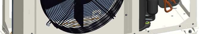
6 System Design Positioning the Heat Pump The heat pump should be kept upright at all times, as oil from the compressor could flow into the refrigeration circuit and cause damage to the unit. Care must be taken when installing the AEC heat pump to ensure that the unit operates effectively. The following variables need to be taken into consideration when positioning the unit: The Heat pump emits cool air from the front through the fan, this should be taken into consideration before installation so as not to cause a problem. All heat pumps do produce some noise. The potential nuisance factor should be discussed with the end user when considering the position of the heat pump. The planning standard limit is 42dBA (at time of writing). A calculation should been made, taking into account positioning and distance from neighbouring properties (use MCS standard MCS020). An external temperature sensor is fitted to the rear of the unit, care must be taken to ensure this sensor is not influenced by direct sunlight. Select a location where easy wiring and pipe access is available. To prevent the possibility of the unit vibrating and causing annoyance, the unit should be fitted on Anti-vibration mounts. The unit should be installed on a flat, stable base, with adequate provision for the condensate to drain away. 6


7 System Design Positioning the Heat Pump When installing the unit in a location where it is exposed to strong wind, do not face the air outlet of the unit directly into the prevailing winds. Strong wind entering the air outlet may impede the normal airflow and it may affect performance Taking the above into account the unit should be securely installed on a structure that can sustain its weight at a minimum distance of 300mm from the nearest wall (fig.1). 7
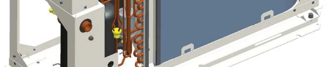
8 System Design Preparation Prior to installing the heat pump, the primary heating circuit should be cleansed using a suitable cleaning agent, to clear any contaminants such as flux residue or installation debris out of the circuit. This is also vital when fitting to an existing heating system. Failure to comply could result in poor efficiency or damage to components within the heat pump. The AEC heat pump delivers lower temperature water than a conventional boiler, therefore the heat emitters need to have a larger surface area or be fitted with an integral fan. (For a heat emitter sizing guide visit the MCS website). An accurate heat loss calculation must be made for the property, then the size of the heat pump required can be established Connection Anti-vibration hoses should be fitted to the flow and return to prevent excessive noise or any joints being broken due to vibration. Ensure the fibre washer is fitted to the flexible hose. Screw the hose to the fitting on the rear of the unit. Ensure any pipe work is insulated. Two spanners should always be used for loosening and tightening water connections. *** Do not overtighten fittings*** Always cover the end of the pipe when inserting through the wall, to avoid contaminants getting inside. All external pipe work and connections should be well insulated to ensure optimum performance and to prevent freezing. *Minimum thickness should be 19mm*. 8
9 System Design The outdoor unit, connections and any external pipe work MUST be protected from freezing. An anti-freeze additive (such as Tyfocor L) of the correct quantity (see manufacturer's guidelines) should be added to prevent any internal damage being sustained by the unit. A magnetic filter / Strainer Must be fitted in the return line of the primary circuit to prevent any contaminants from the circuit reaching the heat pump and potentially damaging components. The filter must be cleaned periodically.. Flow Meter The flow meter is not an integrated part of the heat pump but is essential to its operation. It should be fitted to the main water circuit as shown in the diagram below. To ensure correct operation a straight section of pipe should be fitted before and after the flow meter. Inlet 10 x Pipe diameter Outlet = 5 x Pipe diameter 9

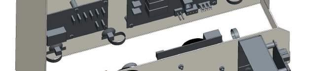
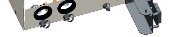
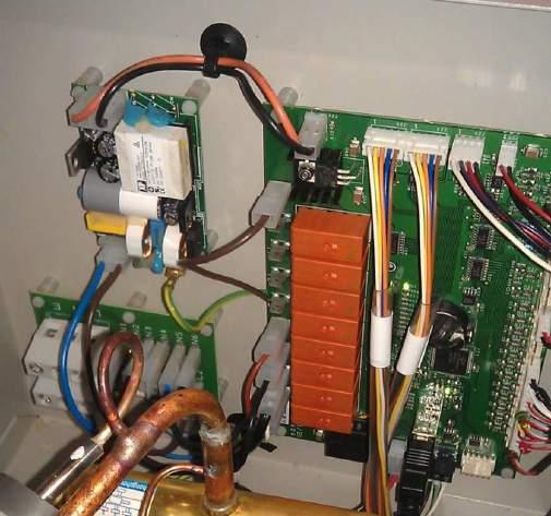
10 System Design Ensure the o rings are fitted as shown below. Ensure that a 1 female to 28mm compression fitting is used for connecting the flow meter to the pipework Flow Meter Wiring The brown wire from the flow meter should be fitted in the left hand communication terminal. The White and blue wires should be fitted to input 6 of the auxiliary PCB as shown below. White wire 10
11 AEC 5 Technical Specification Dimensions (mm) Height Depth Width Weight (kg) 706mm 395mm 980mm 65kg Electrical Supply v, 50Hz Phase Single Running Current (A) [MAX] 13 Fuse Rating (A) 16 Refrigerant Type Quantity Control Compressor Type Model Heat Exchanger Air Water Operating Temperature Range Outdoor Temp. Noise Level (dba) Sound Power Level Sound Pressure at 1 metre R410A 1.7kg Emerson EXM-BOE Hermetic twin rotary TNB220FLHMT Finned Foil Plate Exchanger -20 o C to +35 o C 54dBA 45dBA Air Flow (m3/min) Max (variable) 72.6 Primary Flow Rate Maximum (L/min) 16 Minimum (L/min) 6.5 Unit Capacity (A2/W35) Capacity (kw) 5.4 CoP 3.4 Power Input (kw) 1.6 Nominal Flow Rate (L/min) Unit Capacity (A7/W35) Capacity (kw) 5.5 CoP 4.5 Power Input (kw) 1.2 Nominal Flow Rate (L/min)
12 AEC 5 Unit Dimensions 12
13 AEC 9 Technical Specification Dimensions (mm) Height Depth Width Weight (kg) 1012mm 395mm 1032mm 85kg Electrical Supply v, 50Hz Phase Single Running Current (A) [MAX] 23 Fuse Rating (A) 25 (Recommended 32 A) Refrigerant Type Quantity Control Compressor Type Model Heat Exchanger Air Water Operating Temperature Range Outdoor Temp. Noise Level (dba) Sound Pressure Level Sound Pressure at 1 metre R410A 2.4kg Emerson EXM-BOE Hermetic twin rotary TNB220FLHMT Finned Foil Plate Exchanger -20 o C to +35 o C 57dBA 48dBA Air Flow (m3/min) Max (variable) 72.6 Primary Flow Rate Maximum (L/min) 26 Minimum (L/min) 12 Unit Capacity (A2/W35) Capacity (kw) 9.00 CoP 2.87 Power Input (kw) 3.13 Nominal Flow Rate (L/min) Unit Capacity (A7/W35) Capacity (kw) 9.20 CoP 3.61 Power Input (kw) 2.55 Nominal Flow Rate (L/min)
14 AEC 9 Unit Dimensions 14
15 AEC 9e Technical Specification Dimensions (mm) Height Depth Width Weight (kg) 1012mm 395mm 1300mm 100kg Electrical Supply v, 50Hz Phase Single Running Current (A) [MAX] 23 Fuse Rating (A) 25 (Recommended 32A) Refrigerant Type Quantity Control Compressor Type Model Heat Exchanger Air Water Operating Temperature Range Outdoor Temp. Noise Level (dba) Sound Pressure Level Sound Pressure at 1 metre R410A 2.4kg Emerson EXM-BOE Hermetic twin rotary TNB220FLHMT Finned Foil Plate Exchanger -20 o C to +35 o C 57dBA 48dBA Air Flow (m3/min) Max (variable) 72.6 Primary Flow Rate Maximum (L/min) 26 Minimum (L/min) 12 Unit Capacity (A2/W35) Capacity (kw) 9.00 CoP 2.87 Power Input (kw) 3.13 Nominal Flow Rate (L/min) 25.2 Unit Capacity (A7/W35) Capacity (kw) 9.22 CoP 3.61 Power Input (kw) 2.55 Nominal Flow Rate (L/min)
16 AEC 9e Unit Dimensions 16
17 System Specification Internal Wiring Schematic AEC 5 & AEC 9 Standard 17
18 System Specification Internal Wiring Schematic AEC 9e Enhanced 18
19 System Specification Refrigeration Schematic 19
20 Pipework Schematic Single Zone FLOW METER IMPORTANT: The above system is a concept drawing and not a detailed engineering drawing. It is not intended to describe a particular system An automatic air vent should be installed at the highest point of the system, as air in the system will significantly reduce performance of the heat pump. Alternatively a micro bubble deaerator can be fitted to remove desolved air and increase the efficiency of the system. A buffer tank may be fitted to the system to cover any shortfall in the heating during the heat pump defrost cycle during extreme weather conditions. If a standard AEC is used then an expansion vessel would need to be fitted in the system (the enhanced unit has an expansion vessel and circulation pump fitted). A filling loop can be sited anywhere in the system. If any items are already installed in an existing system they should be checked for integrity and suitability before being re-used. 20
21 Pipework Schematic Multiple Zones FLOW METER IMPORTANT: The above system is a concept drawing and not a detailed engineering drawing. It is not intended to describe a particular system Multiple heating zones can be connected to the AEC unit in the same way as a conventional system. The control equipment will automatically switch between hot water and heating zones as required. Ensure the Domestic hot water zone valve is connected to the correct port on the Auxiliary board. Each model requires sufficient primary flow rate for an efficient operation. Depending on the size of the heat pump used and the size of the system it may be necessary to fit two circulators in series to produce the required flow rate ensuring a delta T of 5 C. Pipe diameter may also need to be increased to reduce resistance, so the required flow rate can be achieved. The primary system should always be unvented as the loop must contain anti freeze. 21
22 Additional Pipework Schematics for Buffer Tanks / Low Loss Headers 22
 of the unit and easily accessible. The electrical circuit should be protected by a dedicated 32A, 30mA RCD. This appliance MUST BE EARTHED.")

 interconnecting cable between the Auxiliary board and heat pump does not carry 240V potential.")
 close to or with mains 240 volt cables.")
23 System Installation Electrical The appliance requires a suitable mains supply rated for the units capacity, an isolator should be placed in close proximity (1.5 m) of the unit and easily accessible. The electrical circuit should be protected by a dedicated 32A, 30mA RCD. This appliance MUST BE EARTHED. Wiring sizes must comply with the applicable local and national codes. 4mm² cable should be the minimum size used, this must be suitably protected from damage. All electrical work carried out should comply with IEE wiring regulations. In the event of an electrical fault after installation of the appliance, the heat pump MUST BE DISCONNECTED BEFORE any tests are carried out. The 4 core (1 mm 2 ) interconnecting cable between the Auxiliary board and heat pump does not carry 240V potential. A Cat 5 ethernet cable should be connected between the heat pump and internal router. Care should be taken not to run communication cables (flow sensor, interconnecting cable) close to or with mains 240 volt cables. Control equipment (pumps, zone valves, thermostats etc) must have a separate circuit from the actual AEC heat pump system and should be protected by the required fuse rating. The AEC outdoor unit and auxiliary PCB should be connected as shown above. The wires should be in identical order in both terminal blocks. 23
24 System Installation Electrical Schematic Two Zone & Hot Water 24
25 System Installation Immersion heater The AEC air source heat pump will produce domestic hot water at 48 C but the temperature should be raised periodically to 65 C for pasteurisation purposes. The immersion heater will raise the water to 65 C once the heat pump has finished its first hot water cycle and will repeat the process every 7 days after that. This process will restart if the heat pump is powered down for any reason. The cylinder temperature sensor (included in kit) should be wired to input 7 on the auxiliary PCB. See diagram on page 24. The DHW heating periods should be timed for when the central heating requirement is lowest. The AEC heat pump has a feature which will ensure that there is sufficient hot water even in the most extreme weather conditions. Commissioning The Auxiliary control board should be located inside the property, near to the control equipment (zone valves, pump, heating controller). The AEC and Flow Temperature Control system require conventional controls. A hot water programmer is required for domestic hot water and a room thermostat for each heating zone. Connections between the heat pump and internal auxiliary control board should contain no intermediate connections, as this may result in communication errors. The zone valve for the DHW cylinder should be connected to zone 3 on the auxiliary board. 25
. The network will be visible with the name (SSID) of 'heatpumpdash'.")
26 System Installation The AEC Dashboard Configuration - Initial Setup The first time that the heat pump controller is powered on, the dashboard will be visible as a WPA/WPA2 encrypted wireless network. This means that you will be able to connect to it with any wireless enabled device (your PC, laptop, tablet, Smart phone etc). The network will be visible with the name (SSID) of 'heatpumpdash'. The network will have a default wireless security key of Once you have connected your wireless device to the network, you will be able to use the dashboard by pointing your browser to Login After entering the default username (admin) and password (admin), you will be able to configure certain aspects of your heat pump through the dashboard interface. 26
 and entering a new password in to the form")
27 System Installation Password Change Before continuing, we recommend that you change the default password by clicking on the small profile icon (top right of the dashboard) and entering a new password in to the form provided. 27

28 System Installation Configuring the Dashboard to your Wireless Network If you wish, the dashboard can be configured to connect to your home wireless network.this is easily enabled from the 'Network Settings' page on the dashboard. You will need to know the following information: The name (SSID) of your local router The type of security used by your router The passphrase/security key to connect to your router **The heat pump should be connected to the router via an ethernet cable. This allows the most reliable signal.** Once you have entered the above details, click on the green 'Submit' button. You will be notified that your wireless settings have been saved and instructed to reboot the heat pump for the settings to take effect. When the heat pump reboots, it will automatically connect to your wireless network and will be visible as a client in your router's web interface. Once the dashboard is connected to your local wireless network, it may be possible for you to access the dashboard from the internet depending on your home router settings (see page 29 for generic details). 28
29 System Installation Accessing your Dashboard from the Internet If you wish to access the dashboard from the internet (outside your home network), there are a few steps that may need to be taken. Assign a static IP address to the dashboard Forward port 80 on your router to your dashboard Use a Dynamic DNS service to maintain a hostname for your network (optional) Assign a Static IP Address to the Dashboard The process of assigning a static IP Address is usually straightforward but does differ depending on the manufacturer of your router. If you have any difficulties performing the above steps, consult the documentation for your router model or check the additional resources listed below. Forward Port 80 to the Dashboard Again, like assigning a static IP address, port forwarding is usually pretty simple to do but depends on the manufacturer of your router. If you have any difficulties performing the above steps, consult the documentation for your router model or check the additional resources listed below. Dynamic DNS Service (optional) Many home networks are given a dynamic internet IP address from their Internet Service Provider. This IP address can change from time to time, meaning you can't reliably connect to your home network. A Dynamic DNS Service can supply you with a free domain name which points to your home network. The service then monitors your IP address and updates DNS records automatically if there is a change. This means that you can always connect to your home network by pointing your browser to the domain name supplied by the DNS service. There are many providers of free dynamic DNS services. Dyn DNS No-IP FreeDNS BUDDYNS 29
30 System Installation Additional Resources The following is a list of useful resources for setting up your local network. PortForward.com (A web site dedicated to the subject of port forwarding. It has detailed instructions covering a huge range of router manufacturers and models) Troubleshooting If you have connected the dashboard to your wireless network and the dashboard loses internet connectivity for more than 10 minutes, it will automatically reboot in to the login screen. You will need to connect to the dashboard (described in 'Initial Set Up') and reconfirm your network settings before the dashboard can reconnect to your local network. If the dashboard is in access point mode, it will be visible from your PC, laptop, smart phone etc. 30

31 System Installation Setup & Monitoring Once connected to the Dashboard it is possible to set up and make adjustments to the AEC air source heat pump. Flow Curve The flow curve can be adjusted via this screen on the dashboard. The desired water temperature can be set depending on the outside temperature, with a lower temperature required during warmer periods. The bivalency values can be set, where the existing heating system will operated depending on ambient temperature. 31


32 System Installation The performance of the heat pump can be monitored, and adjustments can be made to optimise performance. A record of any faults can be accessed to simplify diagnosis and repair, notifications can be sent via . Any Firmware updates can be carried out, even with no access to the site. 32
33 Service, Maintenance & Troubleshooting Service and maintenance The AEC Air Source heat pump must be maintained on an annual basis. The basic requirements are: Remove obstruction from evaporator coil/fan Visual inspection for leaks Check integrity of pipe work insulation Check for loose electrical connections Stop the unit and clean the magnetic filter in accordance with manufacturer s instructions Test the concentration of anti freeze and acidity level of fluid in system System checks can be carried out via the dashboard Unvented cylinders should be serviced annually, as per manufacturer s instructions Servicing should only be carried out by competent installers and any spare parts must only be purchased from Solfex. NEVER bypass safety devices or operate the unit without them being fully operational. Basic Troubleshooting at Installation Fault Solution Heat Pump fails to start Check power supply to heat pump Check the heat pump has sufficient flow Check the thermostats for demand Water is not hot enough Check the heat pump is running continuously Check the heat pump has sufficient flow Check the temperature set points on flow curve and adjust if required Check the heat pump has adequate air flow Water is emitted from outdoor unit During operation water may drain from the unit, this is normal RCD trips Incorrect sizing of RCD Incorrect cable size A component leaking to earth Damage to cable or component 33
34 Service, Maintenance & Troubleshooting Faults and Solutions Fault Description Possible cause Solution Air Flow 1. Unit incorrectly situated 2. Dispruption to air flow due to debris blocking the evaporator coil 3. Fan blade obstructed 4. Fan not operating 5. PCB fail 1. Check unit has correct air flow 2. Check for debris 3. Check fan blade 4. Check fan is functional 5. Test PCB connection Water Flow 1. Flow rate has dropped below the minimum acceptable flow rate (unit will attempt to restart automatically) 1. On installation, have flow and return been connected in reverse 2. Is water pump of correct spec and operational 3. Water leak 4. Blockage or air lock Low Pressure 1. Disconnection of low pressure transducer (16) 2. Evaporator frozen 3. Defective outdoor unit circuit board 1. Check connection (J16) 2. Sensor fail 3. Change outdoor unit circuit board High Pressure 1. Disconnection of high pressure transducer (15) 2. Fault due to defective part 3. Defective outdoor unit circuit board 4. Short water circuit 1. Check connection (J15) 2. Check refrigerant pressure, replace (15) 3. Change outdoor unit circuit board High Discharge 1. Defective sensor (7) 2. Defective control PCB 3. Faulty expansion valve 1. Check sensor 2. Test PCB 3. Check expansion valve 34
35 Service, Maintenance & Troubleshooting Faults and Solutions Cont... Fault Description Possible cause Solution Can Bus Error 1. Connection lost between heat pump and auxiliary 1. Check 4 core cable for damage 2. Check connections on both heat pump and temperature controller Pressure Difference 1. Difference between high pressure temp and low pressure temp too small 1. Compressor fail 2. Inverter fault 3. PCB fault 4. Wiring fault on inverter or PCB No Zones 1. No heating zones asking for heat 1. This is not a fault but will be logged Compressor Low 1. Heat pump attempting to run compressor at a lower speed than it is capable 1. The heat pump will restart automatically PCB Battery 1. The battery powers the real time clock inside the unit. This is checked periodically for function so this event can be ignored. 35


36 Spare Parts


37 Spare Parts Electrical Box (Indoor unit)
38 Spare Parts 5Kw and 9Kw Compact/Standard NO. DESCRIPTION PART NO. 1 5 Kw COMPRESSOR SNB130FGBMT ASSEMBLY H1AA006 9 Kw COMPRESSOR TNB220FLHMT ASSEMBLY H1DA Kw INVERTER CIMR-VCBA0010BAA H1AC036 9 Kw INVERTER CIMR-VCBA0012BAA H1DC036 3 FAN MOTOR ASSEMBLY - 5kW H1AA016 FAN MOTOR ASSEMBLY - 9kW H1DA016 4 EVAPORATOR COIL - 5kW H1AC011 EVAPORATOR COIL - 9kW H1DC011 5 HEAT EXCHANGER - 5kW H1AC230 HEAT EXCHANGER - 9kW H1DC002 6 MAIN PCB H1DC022 7 ECS25US12 PCB - XP POWER (FARNELL ) H1DC023 8 DISTRIBUTION PCB H1DC031 9 INSTALLATION TERMINAL BLOCK PCB H1DC RASPBERRY PI ASSEMBLY H1DA065 WIFI USB DONGLE FOR RASPBERRY PI ( ) H1DC239 SDHC 16GB 200X CLASS 10 CARD (PREMIUM SERIES) H1DC178 AUXILIARY PCB H1DC171 LOW PRESSURE TRANSDUCER WIRE ASSEMBLY - 730mm HIGH PRESSURE TRANSDUCER WIRE ASSEMBLY - 650mm EVAPORATOR IN TEMP SENSOR EVAPORATOR OUT TEMP SENSOR WATER IN TEMP SENSOR WATER OUT TEMP SENSOR CONDENSER TEMP SENSOR AMBIENT TEMP SENSER COMPRESSOR DISCHARGE TEMP SENSOR H1DA034 H1DA035 H1AC H1AC H1AC H1AC H1AC H1AC H1AC HANDLE RS H1DC026 38
39 Installation Parts Installation Parts List S Plan ASHP System Items supplied by Solfex (prices available on request) AEC air source heat pump Flexible hoses** Anti vibration mounts** Magnetic filter** Anti-freeze inhibitor fluid** Flow setter valve Isolating valves for heat pump flow and return connections Unvented water cylinder (sized correctly for the system and complete with thermostat and pressurisation safety kit) Circulating pump (sized to suit system)* Expansion vessel for heating system* (Including sealed systen kit) Air bleed valve(s)* Zone valves Filling loop Insulation for external pipe work Hot water programmer Room thermostat(s) Wiring centre (For circulation pumps / zone valves etc.) Local isolator (rated for external fitting) * The 9Kw standard unit contains a circulating pump, expansion vessel and pressure relief valve. ** Warranty will be invalid if these parts are not fitted. 39
40 40
41 Air Source Heat Pump Commissioning Report Customer Name Site Address Heat pump ID Installation Contractor Commissioning Engineer Commissioning Date AEC approved installer No BEFORE RUNNING THE HEAT PUMP CHECK THE FOLLOWING POINTS Ensure antifreeze is added in accordance with manufacturer's instruction. Check air charge is in expansion vessel. Pressurise primary circuit to 1.5 bar. Open all isolating valves. Bleed ALL air from the system. Commissioning Engineer's Comments Commissioning Engineer's Signature 41
42 Pre-Commissioning Check Sheet System Checks PASS FAIL Comments Installation Location (Outdoor unit) Maintenance Access (Outdoor unit) Maintenance Access (Cylinder) Acceptable air flow (Outdoor unit) Standard of Pipework Standard of Insulation Standard of Electrical Installation (Auxiliary PCB and Outdoor unit Flow meter fitted on main circuit Electrical Isolation 1.5 m from Heat Pump Connection to mains power source Connection of Control wiring (Outdoor unit) Connection of Control wiring (Auxiliary board) Control wire DHW zone valve connected to port 3 Magnetic filter fitted in system Anti-vibration mounts fitted Flexible hoses fitted to flow and return Flow setting device fitted to main circuit Anti-freeze added to system Check air charge in expansion vessel Bleed air from system Pressurise primary circuit to 1.5 bar Type Size Type Operation Status Heat Pump Model No. Serial No. PASS FAIL COMMENTS Noise level from compressor excessive Noise level from Fan excessive Provision made for condensate removal Access to Dashboard NOTE: If a fail is identified above then the fault should be rectified at the commissioning stage. 42
43 AEC Heat Pump Maintenance Check Sheet Maintenance should be carried out annually. Failure to maintain the system may result in the warranty becoming null and void. Customer Name Site Address Installation Contractor Heat pump ID Serial Number of Unit Model Number of Unit Commissioning Date Brief Description of System Check expansion vessel charge pressure (top up if required) Check and Clean the magnetic filter Open primary/ heating safety valve and check it discharges safely Check and if necessary top up system inhibitor / glycol antifreeze Check and release any air from the system Check for loose external electrical connections Check correct rating and type of fuse fitted to the electrical supply Check the correct setting and operation of thermostats Check the operation of motorised valves Check and clean the evaporator Check for signs of oil leaks indicating a refrigerant leak Check integrity of pipework and insulation Carry out system checks via the dashboard Comments 43
44 SOLFEX LTD Units 3 5 Chamleyfold Industrial Estate Bamber Bridge Preston Lancashire PR5 6PS 44
Commissioning Pack. Heating and Hot Water Heat Pumps. IMPORTANT DOCUMENTS To Be Kept At All Times. With Equipment. Accredited Ecodan Installer:
 Accredited Ecodan Installer: Telephone: Email: Address: Commissioning Pack Heating and Hot Water Heat Pumps IMPORTANT DOCUMENTS To Be Kept At All Times With Equipment IMPORTANT This Sheet Must Be Kept
SEALED THERMAL STORE
 ISSUE 3 0717 INSTALLATION AND USER GUIDE ENERGYMANAGER SEALED THERMAL STORE ADVANCE APPLIANCES LTD PLEASE RETAIN AND ENSURE SERVICE RECORDS ARE KEPT UP TO DATE. SCHEMATIC DIAGRAM OF ENERYMANAGER THERMAL
INSTALLATION & TECHNICAL MANUAL
 The COMET Range of Boilers the ultimate solution for central heating INSTALLATION & TECHNICAL MANUAL If you require any further assistance: Telephone: 01698 820533 Fax: 01698 825697 E-mail: info@electric-heatingcompany.co.uk
INSTALLATION & TECHNICAL MANUAL
 The FUSION Range of Boilers INSTALLATION & TECHNICAL MANUAL If you require any further assistance: Telephone: 01698 820533 Fax: 01698 825697 E-mail: info@electric-heatingcompany.co.uk Or visit our website
PLEASE LEAVE THIS MANUAL WITH THE OSO UNIT AFTER INSTALLATION INSTALLATION MANUAL
 PLEASE LEAVE THIS MANUAL WITH THE OSO UNIT AFTER INSTALLATION SOLARCYL IM/SC INSTALLATION MANUAL This manual gives detailed advice for installation and should be read carefully prior to fitting any unvented
Saving energy comes naturally to us.
 Domestic Heat Pumps Saving energy comes naturally to us. Low carbon solutions for heating and hot water The sustainable heating solution for today and tomorrow Home heating with lashings of hot water Whether
TOSHIBA AIR CONDITIONING
 Introduction The following specification describes the Toshiba Estia Air to Water Heat Pump system(s) to be installed at the site below: (ADD SITE NAME) The system(s) shall consist of the following components.
ADVANCE ELECTRIC THERMAL STORE
 ISSUE 13 1118 INSTALLATION AND USER GUIDE ADVANCE ELECTRIC THERMAL STORE ADVANCE APPLIANCES LTD HOUSEHOLDER PLEASE RETAIN AND ENSURE SERVICE RECORDS ARE KEPT UP TO DATE. 2 INTRODUCTION Advance thermal
Baxi Maxflow Combi WM
 Baxi Maxflow Combi WM Gas Fired Wall Mounted Combination Boiler with Unvented Hot Water Storage Please keep these instructions safe. Should you move house, please hand them over to the next occupier. User
Grant Aerona³. Air to Water High Efficiency Heat Pump Range. Installation and Servicing Instructions
 Grant Aerona³ Air to Water High Efficiency Heat Pump Range Installation and Servicing Instructions UK DOC 0109 Rev 2.1 March 2018 Important Note for Installers This manual is intended to guide Installers
Epsilon Echos kw. General information Air-Water unit with scroll compressors driven by DC inverter. Unique selling points
 Epsilon Echos+ 5 38 kw General information Air-Water unit with scroll compressors driven by DC inverter Configuration /LN: Low noise unit /HP: Reversible heat pump /LE /HP: Reversible condensing unit Unique
INSTALLATION MANUAL. Ecoline Geo RI HP PLEASE LEAVE THIS MANUAL WITH THE OSO UNIT AFTER INSTALLATION
 PLEASE LEAVE THIS MANUAL WITH THE OSO UNIT AFTER INSTALLATION Ecoline Geo RI HP INSTALLATION MANUAL The Ecoline GEO is an indirect unvented cylinder designed and approved for use with a heat pump. The
HT V2 HT Split
 Scroll compressor Refrigerant R07C Aqu@Scop HT V Aqu@Scop HT Split High Temperature Air-to-Water Heat Pumps Models -, -7 and 8-9.0 to 7.9kW Aqu@Scop HT V / Aqu@Scop HT Split Installation examples - Single
High temperature air-to-water heat pumps
 Designed to replace conventional boilers and produce domestic hot water 4 High temperature hot water (+65 C) 4 Winter operation (-20 C) 4 High energy efficiency (CP) 4 Compact and quiet 4 Scroll compressors
PLEASE LEAVE THIS MANUAL WITH THE OSO UNIT AFTER INSTALLATION INSTALLATION MANUAL
 PLEASE LEAVE THIS MANUAL WITH THE OSO UNIT AFTER INSTALLATION 0 RD 0 RI 0000-06 IM/ IM/a INSTALLATION MANUAL This manual gives detailed advice for installation and should be read carefully prior to fitting
Grant UK Aerona³. Air to Water High Efficiency Heat Pump Range. Installation and Servicing Instructions
 Grant UK Aerona³ Air to Water High Efficiency Heat Pump Range Installation and Servicing Instructions UK DOC 0109 Rev 1.1 May 2016 Special Tex t Formats The following special text formats are used in this
Samsung EHS Heat Pump Test
 Samsung EHS Heat Pump Test The following questionnaire is designed for installers who have experience with heat pumps, are currently MCS accredited, and who want to fast track their Samsung accreditation
Operating Instructions Model: PRT-TS WiFi RF. 01/13 Version 1 Ref: PRT-TSWIFI RF
 Operating Instructions Model: PRT-TS WiFi RF 01/13 Version 1 Ref: PRT-TSWIFI RF Contents Page Setting up your WiFi Thermostat 2-6 Remote Connection Setup 6-8 Pairing with the Receiver 8-12 Display Symbols
Baxi Maxflow Combi FS
 Baxi Maxflow Combi FS Gas Fired Floor Standing Combination Boiler with Unvented Hot Water Storage Please keep these instructions safe. Should you move house, please hand them over to the next occupier.
Planning guide. Atec.
 www.thermia.com Thermia Värmepumpar is not liable or bound by warranty if these instructions are not adhered to during installation or service. The English language is used for the original instructions.
Grant Aerona³. Air to Water High Efficiency Heat Pump Range. Installation and Servicing Instructions
 Grant Aerona³ Air to Water High Efficiency Heat Pump Range Installation and Servicing Instructions UK DOC 0109 Rev 2.2 October 2018 Important Note for Installers These instructions are intended to guide
Advance Split
 Engineering Data Manual Aqu@Scop Advance Split Air-to-Water DC Inverter Split Heat Pumps Models 005, 008, 012 & 014 2 to 16 kw Strength Points Most efficient heating technology with variable speed compressor.
Air Source Heat Pump Installation and Maintenance Manual
 Air Source Heat Pump Installation and Maintenance Manual Model Numbers: AroTHERM VWZAI wiring centre VRC700 remote controller Scan this code to go directly to our YouTube channel 2016 b 1 The Outdoor Unit
PANDORA HEAT BANKS OXFORD BROOKES, HARCOURT HILL. Operation and Maintenance. THERMAL INTEGRATION LTD. Tel: Internet:
 PANDORA HEAT BANKS OXFORD BROOKES, HARCOURT HILL Operation and Maintenance THERMAL INTEGRATION LTD. Tel: 0845 2411441 Internet: www.heatweb.com Introduction The District Pandora Heat Bank provides hot
Split inverter air-to-water heat pump CERTIFIED BY CERTITA. option 30/35-40/45
 Plug & Heat heat pump Quick and easy to install For new homes or boiler backup operation 50 HFC R410A CERTIFIED BY CERTITA Heating capacity: 5.5 to 22 kw option CERTIFIED BY CERTITA 30/35-40/45 USE The
WALLACE MAXIPUMP 3000, 5000, 6000 and HYDROJET 30P, 30C, 140 AND HJ400 INSTALLATION AND MAINTENANCE INSTRUCTIONS
 6 th June 2006 Page 1 WALLACE MAXIPUMP 3000, 5000, 6000 and HYDROJET 30P, 30C, 140 AND HJ400 INSTALLATION AND MAINTENANCE INSTRUCTIONS Please read and follow all these instructions carefully before proceeding
Unvented Calorifier Range. Operating and Maintenance Manual. For Models & 500
 Unvented Calorifier Range. Operating and Maintenance Manual. For Models 125 300 & 500 Telephone 08456 448802 Fax 08456 448803 Emial info@mhgheating.co.uk Web www.mhgheating.co.uk TABLE OF CONTENTS. Section
Installation, operating and servicing instructions
 English 57-115 - 144-1 - 259 Installation, operating and servicing instructions ITALIA EN 1 ITALIA English INDEX WARnINGS 3 Who should read these instructions 3 Symbols 3 Recommendations 3 Importants notes
A-Class. A-Rated Homes with Dimplex heat pumps. The name you can trust. Building Regulations and Part L Compliance made easy with Dimplex. dimplex.
 A-Class A-Rated Homes with Dimplex heat pumps Building Regulations and Part L Compliance made easy with Dimplex. The name you can trust. dimplex.ie AClass A4 Page Brochure-August 2016.indd 1 A-Class Heat
Grant Aerona³. Air to Water High Efficiency Heat Pump Range. Installation and Servicing Instructions
 Grant Aerona³ Air to Water High Efficiency Heat Pump Range Installation and Servicing Instructions UK DOC 0109 Rev 2.0 June 2017 important note for installers This manual is intended to guide Installers
Daikin ENVi Thermostat installation overview
 Daikin ENVi Thermostat installation overview RESIDENTIAL LIGHT COMMERCIAL COMMERCIAL Presenter s Name Presenter s Title Daikin ENVi system overview (web based thermostat) Slide 2 Daikin ENVi System Overview
Baxi System 100 HE Plus. User s Operating Instructions. Wall Mounted Powered Flue Condensing Gas Fired Central Heating Boiler
 User s Operating Instructions Baxi System 100 HE Plus Wall Mounted Powered Flue Condensing Gas Fired Central Heating Boiler Please keep these instructions safe. Should you move house, please hand them
UK arotherm Schematics and installation guide
 UK arotherm Schematics and installation guide Air to Water Heat Pumps (AWHP) Controls: VRC 700, VR 70, VR 91 The Vaillant heat pump booklet contains documentation to assist in the design, installation
Quantum. Installation, User and Service Manual. Hot Spring
 Hot Spring Domestic Hot Water Cylinder Storage Capacities 90, 125, 150, 170, 200, 250 and 300 Litres 1 Important - This Manual should be left with the householder after installation Index Section Page
Stainless steel range of condensing boilers. Designed to meet carbon reduction targets. Lifetime service and support. Outputs from 50kW to 660kW
 Stainless steel range of condensing boilers Outputs from 50kW to 660kW Designed to meet carbon reduction targets Lifetime service and support Totally dependable. page 1 www.pottertoncommercial.co.uk Contents
Unvented Electric Water Heater 10/15 litre Undersink
 Unvented Electric Water Heater 10/15 litre Undersink Fitting Instructions and User Guide 1 CONTENTS SECTION PAGE 1.0 INTRODUCTION 2 2.0 TECHNICAL SPECIFICATION 3 3.0 INSTALLATION 4 4.0 COMMISSIONING 9
SPECIFICATION GUIDE NEOSYS. Air-cooled Liquid Chiller for outdoor installation (NAC) Nominal cooling capacity: 200 to 460 kw
 Nominal cooling capacity: 200 to 460 kw") SPECIFICATION GUIDE NEOSYS Air-cooled Liquid Chiller for outdoor installation (NAC) Nominal cooling capacity: 200 to 460 kw Air-to-water Heat Pump for outdoor installation (NAH) Nominal cooling capacity:
SPECIFICATION GUIDE NEOSYS Air-cooled Liquid Chiller for outdoor installation (NAC) Nominal cooling capacity: 200 to 460 kw Air-to-water Heat Pump for outdoor installation (NAH) Nominal cooling capacity:
NIBE SPLIT ACVM 270 Air/water heat pump
 NIBE SPLIT ACVM 270 Air/water heat pump NIBE SPLIT ACVM 270 system with complete indoor module NIBE SPLIT ACVM 270 is a complete modern heat pump system that offers effective technical energy saving and
Ecodan Air Source Heat Pump and Flow Temperature Controller 2
 FTC STANDALONE Design, Installation & Servicing Instructions September 2011 Ecodan Air Source Heat Pump and Flow Temperature Controller 2 Flow temperature Controller 2 model Number PAC-IF03IB-E (FTC2)
CMA TECHNICAL MANUAL CONDENSING UNITS FOR OUTDOOR INSTALLATION O L S A F RA N
 E S A RE F R E IG RA N T G TECHNICAL MANUAL -FRIEND Y CONDENSING UNITS FOR OUTDOOR INSTALLATION O L CMA C 2 The manufacturer declines all the responsabilities regarding inaccuracies contained in this manual,
ProCon Streamline Gas Condensing Boiler. Installation and Operating Manual.
 1 MHG Heating Ltd ProCon Streamline Gas Condensing Boiler. Installation and Operating Manual. Unit 4 Epsom Downs Metro Centre, Waterfield, Tadworth, Surrey, KT20 5LR Telephone 08456 448802 Fax 08456 448803
Baxi Combi 133 HE Plus Baxi Combi 100 HE Plus Baxi Combi 80 HE Plus. User s Operating Instructions
 User s Operating Instructions Baxi Combi 133 HE Plus Baxi Combi 100 HE Plus Baxi Combi 80 HE Plus Gas Fired Wall Mounted Condensing Combination Boiler Please keep these instructions safe. Should you move
T550i power shower pump Installation and operating instructions
 power shower pump Installation and operating instructions Installers please note these instructions are to be left with the user 2180149H March 2008 CONTENTS Page Plumbing and electrical notes...1 Introduction...2
Installation, Operating and Maintenance Guide
 Installation, Operating and Maintenance Guide Part no. 780327-C Contents Exposed Exposed Shower Mixing Valve Wall Cover Plate (x2) Strainer (x2) Fixing Screw (x2) Hexagon Key wall Plug (x2) Green Limiter
CROWN WATER HEATERS CPU10 - CPU15 CPOS10 - CPOS15
 CROWN WATER HEATERS CPU10 - CPU15 CPOS10 - CPOS15 COMPACT PLUS 10 and 15 Litre Unvented Under and Over Sink Water Heater INSTALLATION AND USER GUIDE 1 DIMENSIONS 10L - 250mm 15L - 310mm 100mm 80mm 410mm
Powermax HE 85, 115 & 150 Litre Condensing Boilers with Integrated Hot Water Storage
 User s Instructions Quick Guide to the Controls When the Powermax was installed, the Installer should have - left or given you these and other instructions including the Benchmark Log Book and Potterton
Master devices. Type X-AIR-ZMAS. Zone master module for up to 25 zone modules, with integral webserver and interfaces to higher-level systems
 X X testregistrierung Type Web server, also for mobile devices Zone modules Zone master module for up to 25 zone modules, with integral webserver and interfaces to higher-level systems X-AIRCONTROL zone
Installation Manual. Instrucciones de instalación y manual de usuario 1
 Installation Manual Instrucciones de instalación y manual de usuario 1 Installation instructions and user manual V8 2 INDEX 1 GENERAL SAFETY WARNINGS... 4 2 OPERATING PRINCIPLE... 5 3 TECHNICAL FEATURES...
Peak Partners Web-Programmable Thermostat Homeowner s Manual. Look inside for a complete guide to the setup and operation of your new thermostat.
 Peak Partners Web-Programmable Thermostat Homeowner s Manual Look inside for a complete guide to the setup and operation of your new thermostat. Table of Contents Step 1: Getting Started...4-6 A. Thermostat
GB24 & GB30. User Manual
 GB24 & GB30 User Manual BOILER OUTPUT To Domestic Hot Water:To Central Heating: GB24/30 Minimum 8.0 kw (27,296 Btu/h) GB24 Maximum 24.2 kw (82,570 Btu/h) GB30 Maximum 30.3 kw (103,384 Btu/h) GB24/30 Minimum
Samsung Eco Heating System
 Samsung Eco Heating System Pre Sales Technical Information Powerful and eco-friendly air to water solutions for heating 2 Welcome This pre-sales manual has been developed for both the installer and end
FITTING, OPERATION, INSTALLATION & SERVICING INSTRUCTIONS
 TRIANCO Electric System Boiler KM 59690 FITTING, OPERATION, INSTALLATION & SERVICING INSTRUCTIONS To be retained by the householder HEALTH AND SAFETY INFORMATION FOR THE INSTALLER AND SERVICE ENGINEERS
Instructions for Use Installation and Servicing
 0020004886A 18.01.05 Instructions for Use Installation and Servicing To be left with the user 12563 115-150-175-200-250-300 Unvented hot water storage cylinders Glow-worm, Nottingham Road, Belper, Derbyshire.
CMA CONDENSING UNITS FOR OUTDOOR INSTALLATION INSTALLATION AND OPERATION MANUAL
 CMA CONDENSING UNITS FOR OUTDOOR INSTALLATION ECO-FRIENDLY REFRIGERANT GAS INSTALLATION AND OPERATION MANUAL Dear Customer, Thank you for having purchased a FERROLI product. It is the result of many years
Heat 45 & 55. User Instructions FAN POWERED HIGH EFFICIENCY MODULATING DOMESTIC CONDENSING GAS COMBINATION BOILER
 Heat 45 & 55 User Instructions FAN POWERED HIGH EFFICIENCY MODULATING DOMESTIC CONDENSING GAS COMBINATION BOILER CE/PI No. 86-CN-69 Heat 45 - GC No. 41-930-40 Heat 55 - GC No. 41-930-41 These instructions
Added password for IP setup page : Password must be in IP format!
 NETWORK POWER MONITOR Release : 21 August 2014 Hardware Version : Version 7 Firmware version 1.00 PC Application Software : Version (latest)...2 Added password for IP setup page : Password must be in IP
T4000 Security Communicator
 Inner Range T4000 Security Communicator 1 T4000 Security Communicator by Inner Range P/N: 998530 / 998530NZ 998530LT (Lite Version) Installation & Operation Manual. Rev: 1.5 Inner Range Pty. Ltd. www.innerrange.com
ADVANCE ECB ELECTRIC COMBINATION BOILER
 ISSUE ISSUE 45 0115 0317 INSTALLATION AND USER GUIDE ADVANCE ECB ELECTRIC COMBINATION BOILER ADVANCE APPLIANCES LTD HOUSEHOLDER - PLEASE RETAIN AND ENSURE SERVICE RECORDS ARE KEPT UP TO DATE 1 SCHEMATIC
USER GUIDE. IMAX XTRA EL kW. For Installation Guide see reverse of book
 USER GUIDE IMAX XTRA EL 320-620kW For Installation Guide see reverse of book When replacing any part on this appliance, use only spare parts that you can be assured conform to the safety and performance
12/50 CENTRIFUGAL PUMPS FOR DC SUPPLY OPERATING INSTRUCTIONS
 12/50 CENTRIFUGAL PUMPS FOR DC SUPPLY OPERATING INSTRUCTIONS Please leave this instruction booklet with the pump as it contains maintenance and safety information (Original Instructions) MODELS 12/50 INDEX.................
heat interface units A BOILER WITHOUT A FLAME
 A BOILER WITHOUT A FLAME heat interface units Communal Heat Networks A central boiler house will generate heat which is distributed through a network of pipe to each home or apartment in the building.
PLEASE LEAVE THIS MANUAL WITH THE OSO UNIT AFTER INSTALLATION INSTALLATION MANUAL
 PLEASE LEAVE THIS MANUAL WITH THE OSO UNIT AFTER INSTALLATION SLIMLINE INSTALLATION MANUAL This cylinder is manufactured and approved in accordance with EN 897:006. This manual gives detailed advice for
Blue Box Epsilon Echos +
 Blue Box Epsilon Echos + 5 38 kw General information Air-Water unit with scroll compressors driven by DC inverter Packaged version in 5 sizes Nominal cooling capacity (A35;W7): 6 26 kw Nominal heating
Unvented Direct & Indirect Hot Water Cylinders (400L L)
") Unvented Direct & Indirect Hot Water Cylinders (400L - 2500L) Important Please read & understand all these instructions before commencing installation. Please leave this manual with the customer for future
Unvented Direct & Indirect Hot Water Cylinders (400L - 2500L) Important Please read & understand all these instructions before commencing installation. Please leave this manual with the customer for future
Digital Control Unit- Installation, Operation & Maintenance IMPORTANT INFORMATION
 Environment IMPORTANT INFORMATION It is not anticipated that this equipment will be exposed to adverse environmental conditions without additional protection. Site the equipment in a frost free area. Ensure
Alpha CombiMax 350 and 600
 Installation and Servicing Instructions Alpha CombiMax 350 and 600 Unvented Hot Water Store for use with the Alpha 240/280 Range of Gas Fired Combination Boilers For Technical help or for Service call...
INSTALLATION MANUAL. Ecoline Geo RI HP PLEASE LEAVE THIS MANUAL WITH THE OSO UNIT AFTER INSTALLATION
 PLEASE LEAVE THIS MANUAL WITH THE OSO UNIT AFTER INSTALLATION 142039-02 GEO 9-2015 Ecoline Geo RI HP INSTALLATION MANUAL The Ecoline GEO is an indirect unvented cylinder designed and approved for use with
Installation, Operation & Maintenance Instructions
 Installation, Operation & Maintenance Instructions Please leave this instruction booklet with the owner as it contains important guarantee, maintenance and safety information Read this manual carefully
Aluminium range of condensing boilers. Works every time. Designed to meet carbon reduction targets. Lifetime service and support
 Aluminium range of condensing boilers Outputs from 30kW to 600kW Designed to meet carbon reduction targets Lifetime service and support Works every time. www.pottertoncommercial.co.uk Aluminium range of
Installation and User Instructions HS10U, HS15U.
 Installation and User Instructions HS10U, HS15U. MULTIPOINT Please read and understand these instructions before starting work. Please leave this leaflet with the user following installation PACK CONTENTS
Schluter -DITRA-HEAT-E-WiFi Thermostat - Troubleshooting Guide External Use and for Inclusion in User Manual and/or Website
 Schluter -DITRA-HEAT-E-WiFi Thermostat - Troubleshooting Guide External Use and for Inclusion in User Manual and/or Website General/Operational Troubleshooting Guide I have an Error Code: E0 (Thermostat
Efficient heating that won t cost the earth
 Product Range Guide Efficient heating that won t cost the earth CTC is an international manufacturer of innovative renewable heating solutions. For over 90 years our ranges of high performance products
Installation and User Guide Please leave this guide with the end user (for future reference)
") Contact and Commissioning Details Installer Contact Name and Address : Model N : Serial N : Date Installed : Installation and User Guide Please leave this guide with the end user (for future reference)
Contact and Commissioning Details Installer Contact Name and Address : Model N : Serial N : Date Installed : Installation and User Guide Please leave this guide with the end user (for future reference)
DYNACIAT LGN. Description. Split system Water chillers. High energy efficiency Compact and quiet Scroll compressors Brazed-plate heat exchangers
 High energy efficiency Compact and quiet Scroll compressors Brazed-plate heat exchangers Self-adjusting electronic control Cooling capacity: 35 to 700 kw 410A Cooling Operation DYNACIAT - DYNACIAT POWER
Installation & User Instructions
 Grant Aerona Air Source Heat Pump Air to Water Heat Pump Range Installation & User Instructions Tested to BS EN 14511 Part No. DOC.87 Rev.05 January 2011 i STOP STOP! Before continuing with the installation
CRIMSON & CRIMSON MAX
 High efficiency water/water and geothermal heat pumps 5 114 General High efficiency water/water and geothermal heat pumps. Ideal for heating, cooling and production of domestic hotwater with total or partial
Installation, Operation & Maintenance Instructions
 Installation, Operation & Maintenance Instructions Please leave this instruction booklet with the owner as it contains important guarantee, maintenance and safety information Read this manual carefully
Curv-infrared.com. The Smarter Way. To Heat Your Home. Installation & Operating Instructions For Cürv, Flat, Towel Rail and Mirror Infrared Heaters
 Curv-infrared.com The Smarter Way To Heat Your Home Installation & Operating Instructions For Cürv, Flat, Towel Rail and Mirror Infrared Heaters Safety Precautions Important Notice To Purchaser Before
INSTALLATION INSTRUCTIONS POINT OF USE WATER HEATERS EPU - US10 EPU - US15
 INSTALLATION INSTRUCTIONS POINT OF USE WATER HEATERS EPU - US10 EPU - US15 01 CONTENTS Special information 2 General information 3 Safety 5 Appliance description, cleaning, care & maintenance 7 Appliance
PLEASE LEAVE THIS MANUAL WITH THE OSO UNIT AFTER INSTALLATION INSTALLATION MANUAL
 PLEASE LEAVE THIS MANUAL WITH THE OSO UNIT AFTER INSTALLATION 09-0 05-05 INSTALLATION MANUAL This cylinder is manufactured and approved in accordance with EN 897:006. This manual gives detailed advice
Pressurisation units & expansion vessels
 Pressurisation units & expansion vessels Pressurisation units The new generation of microprocessor controlled pressurisation units Standard Unit/Advanced Unit These microprocessor controlled pressurisation
30RB Air-Cooled Liquid Chillers PRODUCT SELECTION DATA. Easy and fast installation. Compact, reliable and efficient
 PRODUCT SELECTION DATA Easy and fast installation Compact, reliable and efficient Class A variable speed circulator available Air-Cooled Liquid Chillers 0RB 008-015 CARRIER participates in the ECP programme
i-chiller 181 to 210 kw ic770 to ic780 ABOUT THE i-chiller RANGE RELIABILITY: ENERGY & PROCESS EFFICIENCY: EASE OF OPERATION & MAINTENANCE:
 ABOUT THE i-chiller RANGE The fully packaged, EcoDesign compliant, air-cooled i-chiller range is designed specifically for reliable and efficient process cooling. The unique evaporator is immersed within
Air to water Heat Pump System
 Air to water Heat Pump System 2 The heating and cooling systems of the future! A step in the right direction of reducing pollution and CO₂ emissions The increase of CO₂ and other green house gases is a
Technical description. Atec.
 www.thermia.com Thermia Värmepumpar is not liable or bound by warranty if these instructions are not adhered to during installation or service. The English language is used for the original instructions.
Congratulations! You've just purchased a new Santon tankless water heater and will soon begin to enjoy the benefits of going tankless.
 by Congratulations! You've just purchased a new Santon tankless water heater and will soon begin to enjoy the benefits of going tankless. Please take the time to thoroughly read and understand this safety
Installer manual AG-WL10
 LEK LED CLEAN TIMER OPERATION Installer manual Indoor unit air/air heat pump IHB GB 1637-1 331827 Table of Contents 1 Important information Safety information Read before starting the installation Electrical
HEAVY DUTY BRASS SHOWER PUMPS
 HEAVY DUTY BRASS SHOWER PUMPS YOUR GUARANTEE IS AT RISK IF PUMP NOT INSTALLED CORRECTLY. SEE SECTION 2 IMPORTANT INSTRUCTIONS Performance Shower Products SERVICE HELPLINE TEL: 01883 730339 1. GENERAL Your
INSTANTANEOUS ELECTRIC SHOWER
 GUARANTEE / SERVICE POLICY INSTANTANEOUS ELECTRIC SHOWER GUARANTEE Designa guarantee this DS3000 product for a period of two years, from date of purchase, against mechanical and electrical defects arising
Installation instructions Danfoss heat pump DHP-R
 Installation instructions Danfoss heat pump DHP-R Table of contents DHP-R 1 Important information........................................................... 5 1.1 Refrigerant...5 1.2 Noise and vibrations...5
TOTAL HEAT RECOVERY MULTI-PURPOSE HEAT PUMPS
 TOTAL HEAT RECOVERY MULTI-PURPOSE HEAT PUMPS Energy saving thanks to a total recovery p Cooling Heating/DHW h Galletti multi-purpose heat pumps are total recovery units used for a simultaneous hot and
30GH Air-Cooled Liquid Chillers 30GH Nominal cooling capacity kw
 Air-Cooled Liquid Chillers Nominal cooling capacity 21-94 kw Carrier is participating in the Eurovent Certification Programme. Products are as listed in the Eurovent Directory of Certified Products. The
SLIM-LINE RC FAN CONVECTOR.
 SLIM-LINE RC FAN CONVECTOR. INSTALLATION, OPERATING, MAINTENANCE & AFTER SALES MANUAL Product Serial Number: Please leave this manual with the end user. Part Number: 1370064 heatingthroughinnovation. Contents
Self-help Temperature Adjustment
 Self-help Temperature Adjustment The Shower Valve temperature is pre-set to 42 C, but on certain installations the temperature may need to be adjusted. Note: The hot water supply must be above 60 C. Turn
Browser Manual ProMinent ProMtrac Cooling Tower Water Treatment Controller
 Browser Manual ProMinent ProMtrac Cooling Tower Water Treatment Controller ProMtrac_Browser_Manual.docx (5/23/13) rev1: pn. 7501088 Please completely read through these operating instructions first! Do
MAX O GAZ. Condensing water heater TECHNICAL MANUAL
 MAX O GAZ Condensing water heater TECHNICAL MANUAL 2 CONTENTS THE COMPONENTS OF THE MAX O GAZ.. 1 4 BALANCED FLUE AND CONVENTIONAL FLUE MAX O GAZ FEATURES. 3 6 INSTALLATION OF THE MAX O GAZ... 5 8 STANDARD
Telephone Helpline: (Australia) Blast Chiller / Freezer. Instruction Manual. Model DN492-A DN494-A
 Blast Chiller / Freezer. Instruction Manual. Model DN492-A DN494-A") Blast Chiller / Freezer Instruction Manual Model DN492-A DN494-A 1 Safety Tips Position on a flat, stable surface. A service agent/qualified technician should carry out installation and any repairs if
Blast Chiller / Freezer Instruction Manual Model DN492-A DN494-A 1 Safety Tips Position on a flat, stable surface. A service agent/qualified technician should carry out installation and any repairs if
PHRIE / PHIE InvERTER monoblock air To water HEaT PumP medium TEmPERaTuRE
 TEcHnIcal InsTRucTIons PHRIE / PHIE InvERTER monoblock air To water HEaT PumP medium TEmPERaTuRE PHRIE 095 PHRIE 1 PHIE 095 PHIE 1 PHRIE 155 PHRIE 157 PHRIE 175 PHRIE 177 PHRIE 195 PHRIE 197 PHRIE 7 PHRIE
Warning: 230V / 1ph / 50Hz V / 3ph / 50Hz. Remarks: Make sure that you have enough power. (See page 15 Cable table)
") 1 2 Warning: - Do not place your hand or any other objects into the air outlet and fan. It could damage the heat pump and cause injuries; - In case of any abnormality with the heat pump, cut off the power
1 2 Warning: - Do not place your hand or any other objects into the air outlet and fan. It could damage the heat pump and cause injuries; - In case of any abnormality with the heat pump, cut off the power
PowerRouter application guideline
 PowerRouter application guideline Software installation tool - version 3.4 Before operating the PowerRouter, you may initialize the PowerRouter by using the PowerRouter software installation tool. The