Electro Industries Make-Up Air II
|
|
|
- Roxanne Skinner
- 5 years ago
- Views:
Transcription
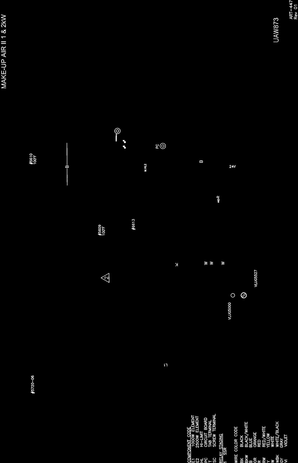
1 Installation & Operating Manual Electro Industries Make-Up Air II Included With This Product Permanent washable air filter Powered inlet damper Temperature sensor Chain kit for ceiling installations Models EM-MA01 & EM-MA02 Other Requirements Turn-on device (switch closure) connected to R & W (Class II wiring) High voltage wiring Fresh air intake wall vent Inlet/outlet ductwork Application This product aids in preventing building depressurization where there is an exhaust blower/fan, coupled with a tight building envelope. UL Standard 1995, CSA C22.2 NO Drawings: UAW873, XX017 DO NOT DESTROY THIS MANUAL. PLEASE READ CAREFULLY AND KEEP IN A SAFE PLACE FOR FUTURE REFERENCE BY A SERVICE TECHNICIAN. 09/15/2014 EI907
2 Table of Contents Page Product Description 1 Handling & Storage 1 Placement & Mechanical Information 1 Product Configurator 2 Specification Tables 2 Dimensional Drawings 3 Safety Consideration 4 Installation Requirements 4 Installation Overview 5 Mechanical Installation 6 Electrical Installation 8 Control Wiring 8 High Voltage Hookup 9 Basic Setup 10 Operational Indicators 11 Troubleshooting 12 Routine Maintenance 13 Replacement Parts 13 Drawings UAW873 XX017 09/15/2014 EI907
3 Product Description This is a self-contained package with a permanent (washable) air filter, electric heating elements, modulating element temperature control, powered damper and fan. This product has been designed specifically for outside air inlet. All models include WarmFlo electronic outlet temperature sensor and associated control circuitry to modulate the electric elements for a fixed outlet temperature. This means the electric element is only used to make-up or heat the outside fresh air to the preset temperature point. There is no overheating or inefficient use of the electric element. Heating elements are locked out when this unit s outlet air temperature is greater than the set point dial switch. Diagrams used throughout the installation manual represent general installation requirements. Due to various model sizes available, actual unit mechanical and wiring requirements will vary dependent upon specific model. Handling & Storage Receiving It is the receiver s (person and/or company signing off on the receiving Bill of Lading) responsibility to inspect for shipping damage. All shipping claims must be made by the receiver. Storage Packed or unpacked, the Make-Up Air unit shall not be exposed to rain, snow, or other adverse environment. This product is designed for in-building storage and installation only. As much as possible this product must be protected throughout the construction phase to avoid accumulation of dust and moisture on the components and control box. The installing contractor is responsible for maintaining the cleanliness and quality of this unit until installation is complete and approved by the user/end customer. Placement & Mechanical Information This product is designed for zero clearance, but use the following mounting and spacing criteria: 1. Unit can be installed vertically or horizontally. When vertical, inlet must face down. 2. Make mounting provisions for a 1 air space at the top. 3. The sides, any location, can be in direct contact with wood framing materials. 4. No materials shall be in contact with the cabinet housing which has a flame point less than wood, 300 F (150 C). 5. Product shall be installed in a conditioned space only. 6. Heating elements are locked out when outlet air temperature is > set point dial switch. 09/15/ EI907
4 Product Configurator EM-MA Option Collar Size A = 06 = 6 X = No Damper 08 = 8 10 = 10 kw 14 = = 1 kw 02 = 1.6 kw Phase 03 = 3 kw 1 = Single phase 05 = 5 kw 3 = Three phase 06 = 6 kw 10 = 10 kw Volts 15 = 15 kw 120 = 120-volt 20 = 20 kw 240 = 240-volt 14 = 14 kw 208 = 208-volt (3-phase) 22 = 22 kw Specification Tables Temperature Rise & CFM Chart (this model series) Required Temp Rise Specifications SINGLE PHASE MODELS Model MA01 MA02 CFM CFM 80 F F F F F F Model kw Btu/h Amps Internal CB Motor FLA Motor HP Phase Voltage Max CFM Static Max Fuse/ HACR Duct Connection Shipping Weight EM-MA , N/A 0.5 1/ / EM-MA , N/A 0.5 1/ / EM-MA , N/A 0.4 1/ / EM-MA , N/A 0.8 1/5 1-50/ EM-MA , /3 1-50/ EM-MA , /2 1-50/ EM-MA , N/A 0.4 1/ / EM-MA , N/A 0.4 1/ / EM-MA , /3 3-50/ EM-MA , /2 3-50/ /15/ EI907
5 Dimensional Drawings 09/15/ EI907
6 Safety Consideration WARNING BEFORE PERFORMING SERVICE OR MAINTENANCE OPERATIONS ON A SYSTEM, TURN OFF MAIN POWER SWITCHES TO THE INDOOR UNIT. IF APPLICABLE, TURN OFF THE ACCESSORY HEATER POWER SWITCH. ELECTRICAL SHOCK COULD CAUSE PERSONAL INJURY. Installing and servicing electric heating equipment can be hazardous due high voltage and electrical components. Only trained and qualified service personnel should install, repair or service heating and air conditioning equipment. Untrained personnel can perform the basic maintenance functions of cleaning coils and cleaning and replacing filters. All other operations should be performed by trained service personnel. When working on heating and air conditioning equipment, observe precautions in the literature, tags and labels attached to the unit and other safety precautions that may apply, such as the following safety measures: Follow all safety codes. Wear safety glasses and work gloves. Installation Requirements 1. All installation work must be performed by trained, qualified contractors or technicians. Electro Industries sponsors installation and service schools to assist the installer. Visit our Website at for upcoming service schools. WARNING ALL ELECTRICAL WIRING MUST BE IN ACCORDANCE WITH NATIONAL ELECTRIC CODE AND LOCAL ELECTRIC CODES, ORDINANCES, AND REGULATIONS. WARNING OBSERVE ELECTRIC POLARITY AND WIRING COLORS. FAILURE TO OBSERVE COULD CAUSE ELECTRIC SHOCK AND/OR DAMAGE TO THE EQUIPMENT. CAUTION This unit can only be used for its intended design as described in this manual. Any internal wiring changes, modifications to the circuit board, modifications or bypass of any controls, or installation practices not according to the details of this manual will void the product warranty, the safety certification label, and manufacturer product liability. Electro Industries cannot be held responsible for field modifications, incorrect installations, and conditions which may bypass or compromise the built-in safety features and controls. CAUTION This unit shall not be operated (either heating section or blower) until the interior of the structure is completed and cleaned. This also means all duct work must be complete with filter, etc. Manufacturer s warranty is void if this unit is operated during structure construction. CAUTION Hazards or unsafe practices could result in property damage, product damage, severe personal injury and/or death. 2. At Electro Industries the safety of the installer and the end user is of highest priority. Remember, safety is the installer s responsibility and the installer must know this product well enough to instruct the end user on its safe use. Professional installers should be trained and experienced in the areas of handling electrical components, sheet metal products, and material handling processes. 09/15/ EI907


 - Current sensing switch, building exhaust fan/blower - Relay")

7 Installation Overview This Make-Up Air unit contains interface/logic devices, outlet temperature sensor, power open/spring close damper, permanent washable filter and fan motor. Based on the application, other system components may be required to make your system operate as desired. These components must be provided by the installing contractor. These components may include but are not limited to: Outside inlet hood Insulated inlet ducting Outlet ducting The turn-on method or switch - Remote damper with END switch (also see Control Wiring section) - Current sensing switch, building exhaust fan/blower - Relay contact detecting the building exhaust fan/blower running Source power wiring Refer to the below diagrams which show various system configurations. Make-Up Air Independent System Make-Up Air Combined Return Tie-In & Independent System Make-Up Air Return Tie-In System 09/15/ EI907
8 Mechanical Installation This product is designed for zero clearance, but use the following mounting and spacing criteria: 1. Unit can be installed vertically or horizontally. When vertical, inlet must face down. 2. Observe the airflow direction decal and the inlet decal. 3. Make mounting provisions for a 1 air space at the top. 4. The sides, any location, can be in direct contact with wood framing materials. 5. No materials shall be in contact with the cabinet housing which has a flame point less than wood, 300 F (150 C). 6. Product shall be installed in a conditioned space only. 7. Heating elements are locked out when outlet air temperature is > set point dial switch. General: 1. Select a location which will provide minimal noise vibration and minimal fan noise to the building occupants. 2. The outside hood and ducting material are not included with this unit. It is the installer s responsibility to provide the necessary weather protection for the inlet. In cold climates, insulated ducting must be used between the outside inlet air hood and the inlet of this unit. 3. Install unit with a slight air inlet incline (housing outlet end is ¼ higher than inlet end). 4. The unit can be mounted within the ceiling (between joists where it will fit) or ceiling hung, at any convenient location between the outside inlet hood and the fresh air discharge connection. The discharge connection is wherever the conditioned fresh air is distributed within the building furnace cold air return, special ducting, hallway register, furnace room, etc inlet and outlet ducting is adequate for these two mini models. Note: In cold climates, frost and or condensation may collect on metal parts of this product. External field provided insulation may be required in certain situations. The inlet damper and insulated inlet piping will prevent cold air migration and a slight incline will keep moisture collection at the inlet end. 09/15/ EI907
9 Horizontal installation Ceiling Mount Vertical Installation Wall Mount Horizontal installation Wall Mount Option A: Cover Facing Down Option B: Cover Facing Side 09/15/ EI907
10 Electrical Installation Temperature Sensor Heated air outlet temperature sensor is included. Without proper installation of this probe the Make- Up Air unit will not operate correctly. The sensor probe/cable is attached to the control board. However, the sensor probe must be installed external to this unit. Install in the warm air outlet duct, 24 to 36 away from discharge fan. Control Wiring Dry Type Switch Contact This on and off control contact applied across R and W depends upon installation requirements and can take on several possibilities: Pressure differential switch CT with integrated switch contact Relay across exhaust blower motor End switch associated with exhaust damper/motor Connection Details Connect one side of the field provided switch to the TB1 R and the other side of the switch to the TB1 W. External Damper, Field Furnished and Installed If this installation requires or desires a power damper at the through-wall hood, this can be field furnished and wired using the following guidelines: Required is a 24VAC power to open, spring close. Note: It is assumed the existing power damper will be removed, damper blocked open, or actually used in parallel with the field added damper. External damper without end switch: 1. Locate the two wires connected to the existing damper (violet and gray). 2. Splice and extend these two wires (powered to open) to the external damper, powered to open. External damper with end switch: 1. The external damper motor is driven from the exhaust blower turn-on contact closure or device. 2. Locate the external damper END switch closed when open contact terminals or two wires. 3. Extend these two wires to the R and W terminal block. 4. Sequence: a. With this arrangement (paragraph 1 above) there is no other turn-on device (current switch, thermostat, airflow switch, etc.) b. When the exhaust blower comes on, that same component or mechanism also opens this external damper. c. When the external damper end switch closes it turns on this Make-Up Air unit, at R to W. d. All other functions now begin with the R to W turn-on. 09/15/ EI907
11 High Voltage Hookup Service Panel Circuit Breaker(s) Sizing based upon unit size, the specification page shows appropriate service size requirements based on UL and NEC code. Note: These two models require 120VAC source (not 240). Source Power route and install proper current carrying conductors as per local code requirements, from service panel. Nameplate shows current and kw rating. Use copper wire only. Safety Ground copper wire is required, do not depend upon metal conduit. 09/15/ EI907
12 Basic Setup Temperature Set Point Located on the control board is a dial labeled SW1. This dial is used to set the desired output temperature. Setting the desired output temperature is completed in two steps. See Figure 1 for temperature ranges. Step 1 Determine the required temperature output for the application. o HINT: Most Make-Up Air applications suggest an output set point typically around 50 F. Step 2 using a small screwdriver, adjust the SET POINT dial according to the desired operating temperature. FIGURE 1 SET POINT Switch Position F Factory default, position 6 (50 F) Fan Speed Adjustment located in the hinged cover low voltage compartment and on the divider is a plastic shaft knob which allows for fine tuning the fan speed. If you do not need full CFM for your application and desire a larger temperature rise, the lower factory default set speed may be adequate. However, you must realize the CFM must maintain the appropriate requirement for balancing the building inlet to the outlet mechanical driven air. NOTE: Factory default setting is low, full CW. To increase speed turn dial CCW. COMMENT: The fan low speed CFM is approximately /15/ EI907
13 Operational Indicators Green LED on control board. Full on = low voltage present and okay, micro controller is functioning, etc. One pulse = electric heating element is active (set point is still controlling actual element on/off). Two pulses = bad outlet temperature sensor. Three pulses = control hi-limit open. R to W closed contact external switch device. Fan is running. Inlet damper is opening and held open. - Inlet damper is spring close. Control board heat active (set point is still controlling actual element on/off). Fan relationship to electric heating elements fan comes on immediate with R to W contact. There is a 30-second delay before elements turn on (outlet sensor needs to measure inlet air, not room air). The fan also purges the inside elements and warm air after R to W is open for 60 seconds. Hi-limit, manual reset all operations seem normal, but the heating element power is interrupted. The reset button is in the hinged door compartment, on control box divider. Auto reset hi-limits there are two. Temperature control, at fan inlet, this is set for an approximate 90 outlet temperature. It is in the low voltage logic control circuit. LED will show 3 pulses. Comment this is in addition to the outlet temperature sensor mounted within the discharge duct which responds to the set point temperature dial. Element current carrying leg within the sheet metal housing/inside deflectors, this is a safety hilimit in case there is a fan failure or major inlet air restriction. Disconnected or bad detected sensor LED will show two pulses. The electric elements or heat active is at 100% on, follows the R-W input. With an inactive duct sensor the electric elements are no longer controlled at set point. 09/15/ EI907
14 Troubleshooting 1. This product contains several interference suppression components, but as an electronic logic product unpredictable and unusual transients or interferences may sometimes cause strange results. If this product is acting strange, turn off the source power, count to 10, and reenergize. 2. Terminal blocks are clamp-down type. If there is no wire connected and the screw is loose, the screw may not necessarily make a good electrical contact to the inside components. Example if you are jumpering the thermostat terminals without thermostat wire connection or if you are attempting to measure voltage on a screw head, you may get erroneous or unpredictable results if the screw is not tightened down. 3. Use general heating system logic information and basic understanding of the terminal block wiring functions when measuring voltage to determine proper operation of this module. Outlet Temperature Sensor See previous page relating to LED indication and bad sensor operation. The green LED is an indication that the micro program cannot read a temperature value. This sensor test or indication does not determine a bad temperature reading, it simply indicates there is software communication to the sensor itself. Temperature Sensor Detail Red wire to J2-1 +5VDC or RED Black wire to J2-2 DATA or BLK White wire to J2-3 COM or WHT Air Filter A dirty filter can lead to poor system performance and eventual hi-limiting. It is suggested to wash filter at least twice per year. See Routine Maintenance for instruction on how to wash the filter. Control Fuse The low voltage source fuse is a 2A fast blow. A spare fuse is included (next to the operating fuse). Manual Reset Hi-Limit Inside the hinged door compartment is a small red button for manually resetting the highest temperature safety cutout limit. The small red stem will be out approximately ¼, and there is a snap feeling if it was activated or opened. Using indicator lights, etc. to troubleshoot this manual reset must be carefully thought through. The four indicators are: Control board LED, one pulse SSR (triac) LED will be on No element amps or current No heat COMMENT: A bad SSR (triac) may have the same observation as an activated manual reset, diagnose carefully. 09/15/ EI907
15 Routine Maintenance Filter this unit includes an air filter which is a permanent and washable filter. Suggest at least twice per year removing filter and using standard household water to back flush collected dust/debris. Remove screws from small door, opposite the hinged door end Filter is simply held within channels Replacement Parts Part Number Description 4037KIT REPLACE TRIAC SSR 50AMP VAC 4341 BLOWER SPEED CONTROL 120V 5541 TRANSFORMER 120/240:24 40VA CHNN 5609 LIMIT VAC 5610 LIMIT O-99/C LIMIT 150F CAP BULB MAN RESET 5621 ELEMENT EM RND 2.5@ OHM 6613 ELEMENT WX 1@ OHM EMMUM5614 PCB MUA II 1&2KW WF ONLY/ KNOB SPD UFUSE0440 FUSE 2A 250V GLASS FAST ACT VLUG5527 LUG 2 POLE 4-14AWG QUICK CONNECT 09/15/ EI907
16
 years from date of original purchase, that the product and product parts manufactured by Electro Industries,")
17 Electro Industries, Inc. Residential Limited Product Warranty Effective November 1, 2009 Electro Industries, Inc. warrants to the original owner, at the original installation site, for a period of two (2) years from date of original purchase, that the product and product parts manufactured by Electro Industries, Inc. are free from manufacturing defects in materials and workmanship, when used under normal conditions and when such product has not been modified or changed in any manner after leaving the plant of Electro Industries, Inc. If any product or product parts manufactured by Electro Industries, Inc. are found to have manufacturing defects in materials or workmanship, such will be repaired or replaced by Electro Industries, Inc. Electro Industries, Inc., shall have the opportunity to directly, or through its authorized representative, examine and inspect the alleged defective product or product parts. Electro Industries, Inc. may request that the materials be returned to Electro Industries, Inc. at owner s expense for factory inspection. The determination as to whether product or product parts shall be repaired, or in the alternative, replaced, shall be made by Electro Industries, Inc. or its authorized representative. Electro Industries, Inc. will cover labor costs according to the Repair / Replacement Labor Allowance Schedule for a period of ninety (90) days from the date of original purchase, to the original owner, at the original installation site. The Repair / Replacement Labor Allowance is designed to reduce the cost of repairs. This Repair / Replacement Labor Allowance may not cover the entire labor fee charged by your dealer / contractor. TWENTY YEAR (20) LIMITED WARRANTY ON BOILER ELEMENTS AND VESSELS Electro Industries, Inc. warrants that the boiler elements and vessels of its products are free from defects in materials and workmanship through the twentieth year following date of original purchase. If any boiler elements or vessels are found to have a manufacturing defect in materials or workmanship, Electro Industries, Inc. will replace them. TWENTY YEAR (20) LIMITED WARRANTY ON SPIN FIN ELEMENTS Electro Industries, Inc. warrants that the spin fin elements of its products are free from defects in materials and workmanship through the twentieth year following date of original purchase. If any spin fin elements are found to have a manufacturing defect in materials or workmanship, Electro Industries, Inc. will replace them. FIVE YEAR (5) LIMITED WARRANTY ON OPEN WIRE ELEMENTS Electro Industries, Inc. warrants that the open wire elements of its products are free from defects in materials and workmanship through the fifth year following date of original purchase. If any open wire elements are found to have a manufacturing defect in materials or workmanship, Electro Industries, Inc. will replace them. Page 1 of 2 XX017
18 CONDITIONS AND LIMITATIONS: 1. This warranty is limited to residential, single family dwelling installations only. Any commercial or multi-unit dwelling installations fall under the Electro Industries Commercial Limited Product Warranty. 2. Electro Industries, Inc. shall not be liable for performance related issues resulting from improper installation, improper sizing, improper duct or distribution system, or any other installation deficiencies. 3. If at the time of a request for service the original owner cannot provide an original sales receipt or a warranty card registration then the warranty period for the product will have deemed to begin the date the product is shipped from the factory and NOT the date of original purchase. 4. The product must have been sold and installed by a licensed electrician, plumbing, or heating contractor. 5. The application and installation of the product must be in compliance with Electro Industries, Inc. specifications, as stated in the installation and instruction manual, and all state, provincial and federal codes and statutes. If not, the warranty will be null and void. 6. The purchaser shall have maintained the product in accordance with the manual that accompanies the unit. Annually, a qualified and licensed contractor must inspect the product to assure it is in proper working condition. 7. All related heating components must be maintained in good operating condition. 8. All lines must be checked to confirm that all condensation drains properly from the unit. 9. Replacement of a product or product part under this limited warranty does not extend the warranty term or period. 10. Replacement product parts are warranted to be free from defects in material and workmanship for ninety (90) days from the date of installation. All exclusions, conditions, and limitations expressed in this warranty apply. 11. Before warranty claims will be honored, Electro Industries, Inc. shall have the opportunity to directly, or through its authorized representative, examine and inspect the alleged defective product or product parts. Remedies under this warranty are limited to repairing or replacing alleged defective product or product parts. The decision whether to repair or, in the alternative, replace products or product parts shall be made by Electro Industries, Inc. or its authorized representative. THIS WARRANTY DOES NOT COVER: 1. Costs for labor for diagnosis, removal or reinstallation of an alleged defective product or product part, transportation to Electro Industries, Inc., and any other materials necessary to perform the exchange, except as stated in this warranty. Replacement material will be invoiced to the distributor in the usual manner and will be subject to adjustment upon verification of defect. 2. Any product or product part that has been damaged as a result of being improperly serviced or operated, including, but not limited to, the following: operated during construction phase, with insufficient water or air flow; allowed to freeze; subjected to flood conditions; subjected to improper voltages or power supplies; operated with air flow or water conditions and/or fuels or additives which cause unusual deposits or corrosion in or on the product; chemical or galvanic erosion; improper maintenance or subject to any other abuse or negligence. 3. Any product or product part that has been damaged as a result of natural disasters, including, but not limited to, lightning, fire, earthquake, hurricanes, tornadoes or floods. 4. Any product or product part that has been damaged as a result of shipment or handling by the freight carrier. It is the receiver s responsibility to claim and process freight damage with the carrier. 5. Any product or product part that has been defaced, abused or suffered unusual wear and tear as determined by Electro Industries, Inc. or its authorized representative. 6. Workmanship of any installer of the product or product part. This warranty does not assume any liability of any nature for unsatisfactory performance caused by improper installation. 7. Transportation charges for any replacement product, product part or component, service calls, normal maintenance; replacement of fuses, filters, refrigerant, etc. THESE WARRANTIES DO NOT EXTEND TO ANYONE EXCEPT THE ORIGINAL PURCHASER AT RETAIL AND ONLY WHEN THE PRODUCT IS IN THE ORIGINAL INSTALLATION SITE. THE REMEDIES SET FORTH HEREIN ARE EXCLUSIVE. ALL IMPLIED WARRANTIES, INCLUDING WARRANTIES OF MERCHANTABILITY AND FITNESS FOR A PARTICULAR PURPOSE, ARE HEREBY DISCLAIMED WITH RESPECT TO ALL PURCHASERS OR OWNERS. ELECTRO INDUSTRIES, INC. IS NOT BOUND BY PROMISES MADE BY OTHERS BEYOND THE TERMS OF THESE WARRANTIES. FAILURE TO RETURN THE WARRANTY CARD SHALL HAVE NO EFFECT ON THE DISCLAIMER OF THESE IMPLIED WARRANTIES. ALL EXPRESS WARRANTIES SHALL BE LIMITED TO THE DURATION OF THIS EXPRESS LIMITED WARRANTIES SET FORTH HEREIN AND EXCLUDE ANY LIABILITY FOR CONSEQUENTIAL OR INCIDENTAL DAMAGES RESULTING FROM THE BREACH THEREOF. SOME STATES OR PROVINCES DO NOT ALLOW THE EXCLUSION OR LIMITATION OF INCIDENTAL OR CONSEQUENTIAL DAMAGES, SO THE ABOVE LIMITATIONS OR EXCLUSIONS MAY NOT APPLY. PRODUCTS OR PARTS OF OTHER MANUFACTURERS ATTACHED ARE SPECIFICALLY EXCLUDED FROM THE WARRANTY. THIS WARRANTY GIVES YOU SPECIFIC LEGAL RIGHTS, AND YOU MAY HAVE OTHER RIGHTS WHICH VARY UNDER THE LAWS OF EACH STATE. IF ANY PROVISION OF THIS WARRANTY IS PROHIBITED OR INVALID UNDER APPLICABLE STATE OR PROVINCIAL LAW, THAT PROVISION SHALL BE INEFFECTIVE TO THE EXTENT OF THE PROHIBITION OR INVALIDITY WITHOUT INVALIDATING THE REMAINDER OF THE AFFECTED PROVISION OR THE OTHER PROVISIONS OF THIS WARRANTY. Page 2 of 2 XX017
Multiple Boilers Electro TS Series Application EB-C-STG5
 Multiple Boilers Electro TS Series Application EB-C-STG5 Drawings: BC025 BX404 BH504 XX017 Information All Electro-Boilers, except Mini-Boiler, have the same control board (EB5623**). The plug-in control
BASIC INSTALLATION AND OPERATION MANUAL
 BASIC INSTALLATION AND OPERATION MANUAL EMDI ** *5 * Size H = 8W x 10D L = 8W x 16D kw Stages 10 = 9.6 kw 2 = 2 15 = 14.4 kw 3 = 3 20 = 19.2 kw NOTE: This Duct Heater may have various installation applications.
WF-DFSLT Dual Fuel Kit
 WF-DFSLT Dual Fuel Kit Trane/American Standard ComfortLink System and/or Roomstat 900 Controller Installation & Operating Instructions Reference WarmFlo Select plenum heater product EM-WU(WD)***D*-SLT
SPA HEATER INSTALLATION, OPERATION AND MAINTENANCE
 SPA INSTALLATION, OPERATION AND MAINTENANCE MODELS: ST SERIES 5.5 & 11kW 240V SINGLE PHASE BEFORE YOU BEGIN CHECK ALL ELECTRICAL CONNECTIONS TO ALL COMPONENTS WITHIN THE FOR TIGHTNESS. CONNECTIONS CAN
ELECTRIC MAKE-UP AIR
 ELECTRIC MAKE-UP AIR WITH WARMFLO CONTROLLER EM-WM**3** 15 = 15 kw 20 = 20 kw 11 = 10 kw, 3-phase 5 = Single phase, 5 kw per stage 4 = 3-phase, 3-stage 6 = 3-phase, 3-stage H = 8w x 10d L = 8w x 16d Specific
be liable for any other loss or damage, whether direct, indirect, incidental or consequential.
 Integrated HydroStat 3200-Plus for Slant Fin Boilers Part No. 48-3200-03 and 48-3200-04 120 VAC Input / 24 VAC Burner Circuit PATENT S. 8.391,708; 7,891,572; 8,844,834; Others Pending INSTALLATION INSTRUCTIONS
FOR EASY, FAST INSTALLATION AND FOR RESULTS
 Page 1 INSTALLATION & OPERATING INSTRUCTIONS FOR FEDERAL FLOOR FURNACE OFB-100 AND OFB100L UNPACK SHIPMENT CAREFULLY AND INSPECT FOR DAMAGE. ALL GOODS ARE CAREFULLY MANUFACTURED, INSPECTED, CHECKED, AND
INSTALLATION INSTRUCTIONS and OPERATING MANUAL. *Aquastat is a registered trademark of Honeywell International, Inc.
 MODEL 3200-Plus Temp Limit / LWCO Control with Thermal Targeting for Water Boilers 120 VAC Input / 24 VAC Burner Circuit PATENT. 8,931,708; 8,844,834; 7,891,572; others pending INSTALLATION INSTRUCTIONS
INSTALLATION, OPERATION AND MAINTENANCE
 INLINE HEATER INSTALLATION, OPERATION AND MAINTENANCE MODELS: ILS SERIES 1.5kW 120V SINGLE PHASE BEFORE YOU BEGIN CHECK ALL ELECTRICAL CONNECTIONS TO ALL COMPONENTS WITHIN THE HEATER FOR TIGHTNESS. CONNECTIONS
INSTALLATION INSTRUCTIONS and OPERATING MANUAL. *Aquastat is a registered trademark of Honeywell International, Inc.
 MODEL 3200-Plus Temp Limit / LWCO Control with Thermal Targeting for Water Boilers 120 VAC Input / 24 VAC Burner Circuit PATENT. 7,891,572 INSTALLATION INSTRUCTIONS and OPERATING MANUAL Saves Fuel Features
WMWLB / WMWFM / WTWLB / WTWFM Series Hydronic Heating Unit
 January 2008 WMWLB / WMWFM / WTWLB / WTWFM Series Hydronic Heating Unit Installation Operation Maintenance The units are designed for permanent up flow, counter flow, or horizontal left or right airflow
FLCH4R Garage and Utility Electric Heater
 FLCH4R Garage and Utility Electric Heater Installation, Operation & Maintenance Instructions Model No. Volts Amps Watts BTU/HR Phase High Low High Low High Low Min Fuse Size* FLCH4R 208 17.3 8.66 3600
Three Phase Simplex. Installation (937) Installation Instructions and Operation/Troubleshooting Manual. Installation of Floats.
 Installation Instructions and Operation/Troubleshooting Manual. Installation of Floats.") Three Phase Simplex Installation Instructions and Operation/Troubleshooting Manual This control panel must be installed and serviced by a licensed electrician in accordance with the National Electric Code
Three Phase Simplex Installation Instructions and Operation/Troubleshooting Manual This control panel must be installed and serviced by a licensed electrician in accordance with the National Electric Code
SPA BLOWER OWNER'S MANUAL XXXX, XXXX, XXXX, XXXX, XXXX, XXXX fax
 SPA BLOWER OWNER'S MANUAL 80015-XXXX, 80016-XXXX, 80017-XXXX, 80018-XXXX, 80019-XXXX, 80020-XXXX fax 888.610.3839 2015 323300-015 6/15 THIS PAGE INTENTIONALLY LEFT BLANK. 2 Operating Instructions and Parts
INSTALLATION INSTRUCTIONS and OPERATING MANUAL. *Aquastat is a registered trademark of Honeywell International, Inc.
 MODEL 3200-Plus Temp Limit / LWCO Control with Thermal Targeting for Water Boilers 120 VAC Input / 24 VAC Burner Circuit PATENT. 8,931,708; 8,844,834; 7,891,572; others pending INSTALLATION INSTRUCTIONS
Safety & Installation Instructions
 Model 6203 & 6202 Zoned Comfort Control Safety & Installation Instructions READ AND SAVE THESE INSTRUCTIONS 61001213A 6202-6203 Zoned Comfort Control Install.indd 1 TABLE OF CONTENTS SAFETY INSTRUCTIONS..........................................
Safety, Installation, and Operation Manual
 Automatic Steam Humidifier Control Safety, Installation, and Operation Manual READ COMPLETE INSTALLATION INSTRUCTIONS BEFORE STARTING. WARNING This product must be installed by a qualified heating and
Installation and Owner Man u al
 T H R E E P H A S E Evaporator Fan Control System Installation and Owner Man u al WARNING The installation of this device should be done only by competent personnel, experienced in electrical wiring, and
Spa Control System OWNER S MANUAL
 LIMITED WARRANTY ONE YEAR LIMITED WARRANTY: UNITED SPAS, INC. warrants, to the original purchaser, the Spa Equipment against defects in materials or workmanship for a period of one year from date of purchase.
Model 8140 & 8141 Fresh Air Ventilator Installation and Operations Manual
 Model 8140 & 8141 Fresh Air Ventilator Installation and Operations Manual FILTER COVER VENTILATION CONTROLLER INLET COLLAR OUTLET COLLAR SAFETY INSTRUCTIONS WARNING 1. 120 Volts may cause serious injury
Safety & Installation Instructions
 Model 6303 & 6302 Zoned Comfort Control Safety & Installation Instructions READ AND SAVE THESE INSTRUCTIONS 61001212A 6302-6303 Zoned Comfort Control Install.indd 1 TABLE OF CONTENTS SAFETY INSTRUCTIONS..........................................
Installation & Maintenance Instructions
 PRH Series Plenum Heaters Installation & Maintenance Instructions Dear Owner, Congratulations! Thank you for purchasing this new heater manufactured by Marley Engineered Products. You have made a wise
Operating Instructions & Parts Manual. Silent Low-Profile Ceiling Fans. Models 3DPE2A, 3DPE3A, 1UBH6B, 1UBH7B, 1UBH8A, 5AE68B, 5AE69A
 Operating Instructions & Parts Manual EN Silent Low-Profile Ceiling Fans Models 3DPE2A, 3DPE3A, 1UBH6B, 1UBH7B, 1UBH8A, 5AE68B, 5AE69A 465933 PLEASE READ AND SAVE THESE INSTRUCTIONS. READ CAREFULLY BEFORE
READ AND SAVE THESE INSTRUCTIONS READ CAREFULLY BEFORE ATTEMPTING TO ASSEMBLE, INSTALL, OPERATE OR MAINTAIN THE PRODUCT DESCRIBED. PROTECT YOURSELF AN
 READ AND SAVE THESE INSTRUCTIONS READ CAREFULLY BEFORE ATTEMPTING TO ASSEMBLE, INSTALL, OPERATE OR MAINTAIN THE PRODUCT DESCRIBED. PROTECT YOURSELF AND OTHERS BY OBSERVING ALL SAFETY INFORMATION. FAILURE
REFRIGERATED DROP-INS (2-6)FT-DI Installation and Operating Manual
FT-DI Installation and Operating Manual") REFRIGERATED DROP-INS (2-6)FT-DI Installation and Operating Manual For service information call 800-544-3057 Please have the following information available before calling. Information can be found on
REFRIGERATED DROP-INS (2-6)FT-DI Installation and Operating Manual For service information call 800-544-3057 Please have the following information available before calling. Information can be found on
Whirlpool Bathtub Model Number: MT618
 INSTALLATION AND OWNER'S MANUAL Whirlpool Bathtub Model Number: MT618 Please carefully read these instructions before you begin to install the products. 07/11 Rev A P/N:100056-03 Thank you for purchasing
Quest Power Electric Heat EHS 62 Pro
 Quest DRY Power 150 Electric Heat EHS 62 Pro Read and Save These Instructions The Quest Power Electric Heat EHS 62 Pro portable, heavy duty electric heater features multiple power receptacles for connection
Sentry LIQUID LEVEL CONTROLLER MODEL 120 OPERATING MANUAL.
 Sentry LIQUID LEVEL CONTROLLER MODEL 120 OPERATING MANUAL www.aquaticsentry.com TABLE OF CONTENTS 1. SAFETY PRECAUTIONS... 3 2. APPLICATION... 3 2.1 HIGH AND LOW LEVEL ALARM 2.2 PUMP DOWN CONTROLLER 2.3
HI Industrial Utility Heater HI Soleus Air International
 HI1-50-03 Industrial Utility Heater HI1-50-03 2010 Soleus Air International Thank you for choosing a Soleus Air Utility Heater. This owner s manual will provide you with valuable information necessary
WIRING DIAGRAMS R410A MODELS PAC 2OAC/2OACH CAC OWC PWC
 WIRING DIAGRAMS R410A MODELS 2OAC/2OACH PAC CAC PWC OWC WIRING 02172017 TABLE OF CONTENTS PAGE 2OACH Deluxe Portable Air-cooled Heat Pump Electronic Controller... 2-3 Piping Schematic... 4 Single Phase
Single Phase Simplex SXL21=3, SXL24=3, SXH21=3, and SXH24=3
 Single Phase Simplex SXL21=3, SXL24=3, SXH21=3, and SXH24=3 Manufactured by SJE-Rhombus Installation Instructions and Operation/Troubleshooting Manual 7000 Apple Tree Avenue Bergen, New York 14416 Phone:
Installation Instructions
 EZXCAB Sizes 016 and 020 High Efficiency Air Filtration System Installation Instructions JAN High Efficiency Air Filtration System Fig. 1 - EZXCAB C04001 NOTE: Read the entire instruction manual before
Warnings 2. Installation Instructions 3. Wiring Instructions 3. Mounting Instructions 4-5. Replacement Element Installation 5. Replacement Parts 5-6
 TABLE OF CONTENTS Warnings 2 Installation Instructions 3 Wiring Instructions 3 Mounting Instructions 4-5 Replacement Element Installation 5 Replacement Parts 5-6 Heater Coverage Areas 6 General Notes 6
ELECTRIC STOVE MODEL CGESS SAFETY INFORMATION AND OPERATION MANUAL
 ELECTRIC STOVE MODEL CGESS SAFETY INFORMATION AND OPERATION MANUAL Read these instructions completely before operating electric stove. Failure to follow them could cause a heater malfunction resulting
Quest Power Electric Heat EHS 31 Pro
 Quest DRY Power 150 Electric Heat EHS 31 Pro Read and Save These Instructions The Power Electric Heat EHS 31 Pro portable, heavy duty electric heater features a built-in 50-amp twist lock receptacle designed
OPERATION & INSTALLATION MANUAL
 OPERATION & INSTALLATION MANUAL Model: SIO 14 & SIO 18 Electric Tankless Hot Water Generators Table of Contents SAFETY INFORMATION... 1 INTRODUCTION... 2 Unit Operation:... 2 Unit Freezing:... 3 Maintenance:...
ALL WEATHER SL-SERIES QUARTZ TUBE ELECTRIC INFRARED RADIANT HEATER INSTALLATION USE & CARE MANUAL
 ALL WEATHER SL-SERIES QUARTZ TUBE ELECTRIC INFRARED RADIANT HEATER TABLE OF CONTENTS: INSTALLATION USE & CARE MANUAL IMPORTANT INFORMATION Assembly Instructions 2 Wiring Instructions 2 Outdoor Installation
Installation, Operation & Service Manual
 Installation, Operation & Service Manual WARNING Improper installation, adjustment, alteration, service or maintenance can result in death, injury or property damage. Read the Installation, Operation and
Owner s Manual Phoenix FireBird
 4201 Lien Rd Madison, WI 53704 Owner s Manual Phoenix FireBird Installation, Operation and Service Instructions Important Instructions Read and Save These Instructions The FireBird portable, heavy duty
Easy installation in both new construction and retrofit. ZB90C ZB110C X2 Multi-Speed Ventilation Fan INSTALLATION GUIDE
 READ AND SAVE THESE INSTRUCTIONS Installer: leave this guide with homeowner. Register your product online at www.broan.ca/register.asp. ZB90C ZB0C X Multi-Speed Ventilation Fan INSTALLATION GUIDE Easy
Warnings 2. Installation Instructions 3. Wiring Instructions 3. Mounting Instructions 4. Replacement Element Installation 5. Replacement Parts 5
 TABLE OF CONTENTS Warnings 2 Installation Instructions 3 Wiring Instructions 3 Mounting Instructions 4 Replacement Element Installation 5 Replacement Parts 5 Heater Coverage Areas 6 General Notes 6 Maintenance
VENSTAR T1070 FAN COIL THERMOSTAT PROGRAMMABLE 2 OR 4 PIPE SYSTEMS OWNER S MANUAL AND INSTALLATION INSTRUCTIONS
 VENSTAR FAN COIL THERMOSTAT FAN COIL THERMOSTAT T1070 NON- PROGRAMMABLE 2 OR 4 PIPE SYSTEMS Remote sensor ready 3 speed fan control Self-prompting adjustment Auto 2-pipe changeover when used with ACC-SENFC
BESF Box Ventilator. Installation & Operating Manual USA CAN READ AND SAVE THESE INSTRUCTIONS
 Installation & Operating Manual 3001806 03.02 USA CAN BESF Box Ventilator READ AND SAVE THESE INSTRUCTIONS 1200 Northmeadow Parkway, STE 180 Roswell, GA 30076 (770) 587-3238 (800) 255-2923 Fax (770) 587-4731
Installation Instructions
 P700U -21NHP Base Non -Programmable Thermostats Installation Instructions Designed and Assembled in the USA. US patents: US20060165149 A1, USD578026 SI, US6205041 B1 A14005 Base Non---Programmable Thermostat
INSTALLATION INSTRUCTIONS
 INSTALLATION INSTRUCTIONS Keep these instructions with the boiler at all times. BOYERTOWN FURNACE CO. PO Box 100 BOYERTOWN, PA 19512 1-610-369-1450 www.boyertownfurnace.com 5-25-12 2 Danger Warning Caution
R Series B & T2 Model
 FRONT R Series B & T2 Model Fan Forced Wall Heaters 4-1/4 (108mm) NOTE: Knockouts in top same dimensions 3-1/4 3-1/4 (108mm) (108mm) as bottom 16-7/8 (429mm) 13-7/8 (352mm) BOTTOM 13-7/8 (352mm) 7-3/4
B SERIES ELECTRIC FURNACE
 MISSISSAUGA, ONTARIO L5T 1H9 TEL.: 905-670-2500 FAX: 905-795-8311 CUSTOMER SERVICE TEL.: 1-888-882-7626 B SERIES ELECTRIC FURNACE! WARNING 1. The user MUST contact a specialized contractor when a failure
INSTALLATION USE & CARE MANUAL ALL WEATHER SL-SERIES QUARTZ TUBE ELECTRIC INFRARED RADIANT HEATER
 INSTALLATION USE & CARE MANUAL ALL WEATHER SL-SERIES QUARTZ TUBE ELECTRIC INFRARED RADIANT HEATER TABLE OF CONTENTS IMPORTANT INFORMATION Warnings 2 Installation Instructions 3 Wiring Instructions 3 Outdoor
IAQ Series. Bosch IAQ Photo Catalytic Oxidizer (PCO) Residential Application. Installation Manual and Owner s Guide
 Residential Application. Installation Manual and Owner s Guide") Installation Manual and Owner s Guide IAQ Series Bosch IAQ Photo Catalytic Oxidizer (PCO) Residential Application PCOB-09012-0--A - 9" PCO BULB PCOB-14024-0--A - 14" PCO BULB 67202220344 Revised 07-12
Installation Manual and Owner s Guide IAQ Series Bosch IAQ Photo Catalytic Oxidizer (PCO) Residential Application PCOB-09012-0--A - 9" PCO BULB PCOB-14024-0--A - 14" PCO BULB 67202220344 Revised 07-12
Panel Mounted Heat Exchangers by Dantherm, Inc.
 Panel Mounted Heat Exchangers by Dantherm, Inc. PRODUCT INFORMATION MANUAL C0028 003 Pinnacle OM Manual Rev AB Page 1 of 14 Dantherm, Inc. 110 Corporate Drive, Suite K Spartanburg, SC 29303 Tel # +1 864
INSTALLATION INSTRUCTIONS and OPERATING MANUAL. *Aquastat is a registered trademark of Honeywell International, Inc.
 MODEL 3250-Plus Temp Limit / LWCO Control with Thermal Targeting for Water Boilers 120 VAC Operating Voltage PATENT. 8,931,708; 8,844,834; 7,891,572; others pending INSTALLATION INSTRUCTIONS and OPERATING
Carbon Monoxide (CO) Detecting Ventilation Fan Controller Model 120VC Single Relay (100/25 PPM) (200/35 PPM)
 Detecting Ventilation Fan Controller Model 120VC Single Relay (100/25 PPM) (200/35 PPM)") Carbon Monoxide (CO) Detecting Ventilation Fan Controller Model 120VC Single Relay 905-0005-01 (100/25 PPM) 905-0005-02 (200/35 PPM) 1. INTRODUCTION Your COSTAR VC carbon monoxide detecting ventilation
Carbon Monoxide (CO) Detecting Ventilation Fan Controller Model 120VC Single Relay 905-0005-01 (100/25 PPM) 905-0005-02 (200/35 PPM) 1. INTRODUCTION Your COSTAR VC carbon monoxide detecting ventilation
MaxLite LED Vapor Tight Linear Fixture
 General Safety Information To reduce the risk of death, personal injury or property damage from fire, electric shock, falling parts, cuts/abrasions, and other hazards read all warnings and instructions
INSTALLATION INSTRUCTIONS and OPERATING MANUAL. *Aquastat is a registered trademark of Honeywell International, Inc.
 MODEL 3150 Combination Low Water Cut-Off & Universal Temperature Limit Control for Oil-Fired Boilers 120 VAC Operating Voltage PATENT S. 7,891,572; 8,931,708 INSTALLATION INSTRUCTIONS and OPERATING MANUAL
36 IN. ELECTIC FIREPLACE FMI MODEL # LEF36 Mounting Base Feet and Wall Mounting Bracket Included
 F3610G FMI PRODUCTS, LLC 36 IN. ELECTIC FIREPLACE FMI MODEL # LEF36 Mounting Base Feet and Wall Mounting Bracket Included FMI Products, LLC TABLE OF CONTENTS Safety Information... 3 Operating Instructions...
e Heater/Exhaust Fan/Light User s Guide
 e Heater/Exhaust Fan/Light User s Guide abflh70l, BFLH85L Item Stock Number(s): BFLH70L, BFLH85L IMPORTANT INSTRUCTIONS - OPERATING MANUAL READ AND SAVE THESE INSTRUCTIONS READ CAREFULLY BEFORE ATTEMPTING
MaxLite LED Round Pendant Highbay Series
 General Safety Information To reduce the risk of death, personal injury or property damage from fire, electric shock, falling parts, cuts/abrasions, and other hazards read all warnings and instructions
Installation & Maintenance Instructions
 Portable High Temperature Blower Attention: Do not operate this heater in explosive areas. Installation & Maintenance Instructions Dear Owner, Congratulations! Thank you for purchasing this new heater
AG Series Electric Heaters
 AG Series Electric Heaters Auxiliary Electric Heat Installation, Operation & Maintenance Instructions 97B0005N04 Table of Contents Overview 3 Vertical Upflow or Downflow Installation - Internal 3 Vertical
INSTALLATION, OPERATION AND MAINTENANCE
 POOL HEATER INSTALLATION, OPERATION AND MAINTENANCE MODELS: PHS-CN SERIES, 5, 8, 4, 0, 6, 45, 54 & 57kW 08V, 40V, 480, 600V SINGLE & THREE PHASE BEFORE YOU BEGIN CHECK ALL ELECTRICAL CONNECTIONS TO ALL
Model 8140 and 8140NC Fresh Air Ventilator Installation and Operating Instructions
 Model 8140 and 8140NC Fresh Air Ventilator Installation and Operating Instructions MODEL 8140 FRESH AIR ILATOR MODEL 8140NC FRESH AIR ILATOR FILTER COVER ILATION CONTROLLER FILTER COVER ILATION TERMINALS
First Year Limited Warranty for Residential Use Condensing Water Boilers (Includes Heat Exchanger and Component Parts)
") THIS GIVES THE ORIGINAL PURCHASER ONLY SPECIFIC LEGAL RIGHTS AND YOU MAY ALSO HAVE OTHER LEGAL RIGHTS WHICH VARY FROM STATE-TO-STATE AND -TO- Our Warranty By this warranty statement ( Limited Warranty
THIS GIVES THE ORIGINAL PURCHASER ONLY SPECIFIC LEGAL RIGHTS AND YOU MAY ALSO HAVE OTHER LEGAL RIGHTS WHICH VARY FROM STATE-TO-STATE AND -TO- Our Warranty By this warranty statement ( Limited Warranty
Instruction Leaflet. Heater with Adjustable Thermostat PLEASE READ AND SAVE THESE IMPORTANT INSTRUCTIONS
 TRUSTED FOR OVER 100 YEARS Heater with Adjustable Thermostat * Fan-Forced Heaters may appear with a different grill design NOTE: A Phillips screwdriver is required for assembly. Instruction Leaflet PLEASE
INSTALLATION & OPERATION MANUAL
 INSTALLATION & OPERATION MANUAL Model TME- * * Balance of model number is determined by customer specifi ed limits and Setbacks. AUTOMATIC SETBACK THERMOSTAT LIGHT SENSING OR CONTACT CLOSURE FOR LOW VOLTAGE
1500 Watt OIL FILLER RADIATOR INSTRUCTION MANUAL. pure indoor living MODEL BOF2001-CN
 pure indoor living 1500 Watt OIL FILLER RADIATOR MODEL BOF2001-CN INSTRUCTION MANUAL If after having read this leaflet, you have any questions or comments on your heater, call 1-800-253-2764 in North America.
ELECTRIC FIREPLACE OWNER S MANUAL
 ELECTRIC FIREPLACE OWNER S MANUAL MODELS EL1346C 4001358 WARNING: If the information in this manual is not followed exactly, a fire or electrical shock may result causing property damage, personal injury
AMERICA AMERICA 52 CEILING FAN INSTALLATION AND OPERATION MANUAL
 AMERICA AMERICA 52 CEILING FAN INSTALLATION AND OPERATION MANUAL Ceiling Fan Weight Including Accessories: 21.00 Lbs. READ AND SAVE THESE INSTRUCTIONS TABLE OF CONTENTS Tools and Materials Required...
Model 8142 and 8142NC Fresh Air Ventilator Installation and Operating Instructions
 Model 8142 and 8142NC Fresh Air Ventilator Installation and Operating Instructions MODEL 8142 FRESH AIR ILATOR MODEL 8142NC FRESH AIR ILATOR OUTLET COLLAR MOUNTING BRACKET ILATION CONTROLLER OUTLET COLLAR
THE BARCLAY HUGGER CEILING FAN INSTALLATION INSTRUCTIONS
 THE BARCLAY HUGGER CEILING FAN INSTALLATION INSTRUCTIONS Please read and save these instructions These instructions are to be used in the installation of the following QUORUM INTERNATIONAL fans... The
Electric Space Heater
 The Choice of Professionals Model No. FUH Series Electric Space Heater Installation & Maintenance Instructions SPECIFICATIONS: FUH 54B Heater Rating and Voltage 5000 W @ 40V 465W @ 40V 333W @ 40V 500W
CONDENSING WATER BOILERS. (Models VLT , Q VX ,
 Our Warranty By this warranty statement ( Limited Warranty ), ECR International, Inc. ( ECR ) issues limited warranties from the date of installation of the applicable Dunkirk Boiler ( Boiler ) to the
Easy installation in both new construction and retrofit
 READ AND SAVE THESE INSTRUCTIONS Installer: leave this guide with homeowner. Register your product online at www.broan.com/register. XB50L XB80L XB0L X Single-Speed Ventilation Fan with Light and Night
INSTALLATION AND OPERATING MANUAL
 INSTALLATION AND OPERATING MANUAL Salad Bars Olive Bars Food Prep Cases Refrigerated Cases with Air-Over Displays Refrigerated Cases with Coppered Cold Well Displays Cases with Under-Counter Refrigerators
RV Products Division INSTALLATION INSTRUCTIONS FOR SERIES PACKAGE AIR CONDITIONER
 RV Products Division INSTALLATION INSTRUCTIONS FOR 46413 SERIES PACKAGE AIR CONDITIONER 1. WARNINGS IMPORTANT NOTICE These instructions are for the use of qualified individuals specially trained and experienced
Air Storm Fans. Air Storm 54 Fiberglass Fan Installation and Operation Manual
 Air Storm 54 Fiberglass Fan Installation and Operation Manual Table of Contents GrowerSELECT General Page... 3 Safety... 4 Warning Labels... 4 Installation... 5 Operation Safety... 5 Maintenance Safety...
e Bath Fan with Light User s Guide
 e Bath Fan with Light User s Guide abfl50uq, BFL60UQ, BFL70, BFL85 Item Stock Number(s): BFL50UQ, BFL60UQ, BFL70, BFL85 IMPORTANT INSTRUCTIONS - OPERATING MANUAL READ AND SAVE THESE INSTRUCTIONS READ CAREFULLY
EBAC MODEL CD425 ( ) INDUSTRIAL DEHUMIDIFIER OWNER S MANUAL
 INDUSTRIAL DEHUMIDIFIER OWNER S MANUAL") EBAC MODEL CD425 (1018110) INDUSTRIAL DEHUMIDIFIER OWNER S MANUAL Ebac Industrial Products, Inc. 700 Thimble Shoals Blvd, Suite 109 Newport News, VA. 23606-2575 Tel: (757) 873 6800 Fax: (757) 873 3632
EBAC MODEL CD425 (1018110) INDUSTRIAL DEHUMIDIFIER OWNER S MANUAL Ebac Industrial Products, Inc. 700 Thimble Shoals Blvd, Suite 109 Newport News, VA. 23606-2575 Tel: (757) 873 6800 Fax: (757) 873 3632
Quest PowerHeat HFC 100 Pro
 Quest PowerHeat HFC 100 Pro Installation, Operation and Maintenance Instructions Read and Save These Instructions This manual is provided to acquaint you with the portable fan coil so that installation,
POLAR TEMP FARM MORTALITY UNIT OPERATION MANUAL
 POLAR TEMP FARM MORTALITY UNIT OPERATION MANUAL www.polartemp.com TABLE OF CONTENT Disclaimer.......................................... Page 3 Inspection, unpacking and FMU setup.................. Page
Installation Operating Maintenance
 PROFILE SERIES PSU10, PSU15, PSU23, PSU30 PSU40 Installation Operating Maintenance Please read these instructions thoroughly before beginning your installation! The Profile series fan convectors are designed
e Bath Fan with Light User s Guide
 e Bath Fan with Light User s Guide abfl125rok Item Stock Number(s): BFL125ROK IMPORTANT INSTRUCTIONS - OPERATING MANUAL READ AND SAVE THESE INSTRUCTIONS READ CAREFULLY BEFORE ATTEMPTING TO ASSEMBLE, INSTALL,
Ui REFRIGERATOR SPEC SHEET
 Ui REFRIGERATOR SPEC SHEET ISOMETRIC VIEW 19 7/8 20 1/2 32 3/4 FRONT VIEW NOTES: 1. CUTOUT DIMENSIONS: 20 1/2"W X 33"L X 20 3/4"D 2. CUTOUT DIMENSIONS ARE FOR REFRIGERATOR ONLY. REFER TO STAINLESS STEEL
MANUAL INSTALLATION. Fan Column. v200 Issue Date: 01/18/ Price Industries Limited. All rights reserved.
 MANUAL INSTALLATION Fan Column v200 Issue Date: 01/18/17 2017 Price Industries Limited. All rights reserved. TABLE OF CONTENTS Product Overview General Safety Information...1 Safety Notices...1 Unit Description...2
INSTALLER'S MANUAL CLEAN BURN TRANSPORT HEATER MODEL: 45 TH
 INSTALLER'S MANUAL CLEAN BURN TRANSPORT HEATER MODEL: 45 TH I89032 PUBLICATION DATE: 4/14/09, Rev. 1 CLEAN BURN PART # 43217 Copyright 2009 Clean Burn, Inc. All rights reserved. No part of this publication
BLOWER ACCESSORY MODEL #FIB100 Español p. 17
 ITEM #0293810 BLOWER ACCESSORY MODEL #FIB100 Español p. 17 Questions, problems, missing parts? Before returning to your retailer, call our customer service department at 1-877-886-5989, 8:00 a.m - 4:30
Installation and Operations Manual
 Installation and Operations Manual H-IM-LLC February 2018 Part No. 25092501 Replaces H-IM-LLC (01/2014) Lead Lag Control System Table of Contents General Safety Information 2 Inspection 2 Warranty Statement
INSTALLATION INSTRUCTIONS
 INSTALLATION INSTRUCTIONS FOR AQUECOIL HYDRONIC HEATING UNITS GENERAL INFORMATION The AQUECOIL Hydronic Heating Unit is offered in many different capacities and physical configurations in order to match
e Bath Fan with Light User s Guide
 e Bath Fan with Light User s Guide abfl100rnl, BFL125RNL Item Stock Number(s): BFL100RNL, BFL125RNL IMPORTANT INSTRUCTIONS - OPERATING MANUAL READ AND SAVE THESE INSTRUCTIONS READ CAREFULLY BEFORE ATTEMPTING
Ion Endeavor Pump Controller Digital Level Control with Pump Alternation and High Water Alarm
 Ion Endeavor Controller Digital Level Control with Alternation Page 1 of 8 General Overview The Ion Endeavor is a pump controller that senses a water level of up to 72", has a configurable water level/pump
52 CEILING FAN. Owner s Manual Models #50336, 50337
 52 CEILING FAN Owner s Manual Models #50336, 50337 If a problem cannot be remedied or you are experiencing difficulty in installation, please contact the Service Department: 1-877-706-3267, 9 a.m.- 5 p.m.
Electric Duct Heaters
 Electric Duct Heaters 12541_Tutco_Catalog.indd 1 3/4/11 8:46:01 AM TYPICAL HEATER CONSTRUCTION TUTCO, the world s largest supplier of open coil heating elements, produces the highest quality products in
INSTALLATION USE & CARE MANUAL ALL WEATHER W-SERIES AND WD-SERIES QUARTZ TUBE ELECTRIC INFRARED RADIANT HEATER
 INSTALLATION USE & CARE MANUAL ALL WEATHER W-SERIES AND WD-SERIES QUARTZ TUBE ELECTRIC INFRARED RADIANT HEATER TABLE OF CONTENTS Warnings 2 Installation Instructions 3 Wiring Instructions 3 Mounting Instructions
VENSTAR T1075 FAN COIL THERMOSTAT 7 DAY PROGRAMMABLE 2 OR 4 PIPE SYSTEMS OWNER S MANUAL AND INSTALLATION INSTRUCTIONS
 VENSTAR FAN COIL THERMOSTAT FAN COIL THERMOSTAT T1075 7 DAY PROGRAMMABLE 2 OR 4 PIPE SYSTEMS 3 Occupied, 1 Unoccupied Override capable 3 speed fan control Auto 2-pipe changeover when used with accessory
POOL HEATER INSTALLATION, OPERATION AND MAINTENANCE
 POOL HEATER INSTALLATION, OPERATION AND MAINTENANCE MODELS: TR SERIES, 5 & 8kW 08V, 40V, 480V, 600V BEFORE YOU BEGIN CHECK ALL ELECTRICAL CONNECTIONS TO ALL COMPONENTS WITHIN THE HEATER FOR TIGHTNESS.
User s Information Manual
 48TJD005-014 48TJE004-014 48TJF004-012 Single-Package Rooftop Heating/Cooling Units User s Information Manual NOTE TO INSTALLER This manual should be left with the equipment owner. FOR YOUR SAFETY Do not
Standard and CELDEK Evaporative Cooler Modules Installation, Operation, and Maintenance Manual
 Standard and CELDEK Evaporative Cooler Modules Installation, Operation, and Maintenance Manual Standard Evaporative Cooler CELDEK Evaporative Cooler RECEIVING AND INSPECTION Upon receiving unit, check
Surna Dehumidifier Operating & Maintenance Manual
 www.surna.com 303.993.5271 Surna Dehumidifier Operating & Maintenance Manual Models: 3-250 Revised: May 2017 Table of Contents Warranty Information 4 Parts List 5 Intended Application 5 Safety Guide 6
INSTALLATION & OPERATING INSTRUCTIONS
 INSTALLATION & OPERATING INSTRUCTIONS MODEL #85747 WARMING DRAWER MANUAL TABLE OF CONTENTS PAGE # SAFETY INSTRUCTIONS.........2 INSTALLATION INSTRUCTIONS......................3 ISLAND INSTALLATION...3
OPERATION AND MAINTENANCE INSTRUCTIONS FOR ROOF TOP HEAT PUMPS AND CEILING PLENUMS
 OPERATION AND MAINTENANCE INSTRUCTIONS FOR ROOF TOP HEAT PUMPS AND CEILING PLENUMS TABLE OF CONTENTS I. General Information.................................................. 2 II. Standard Ceiling Plenum
INSTALLATION & OPERATING INSTRUCTIONS
 ELECTRO-BOILER TS Series INSTALLATION & OPERATING INSTRUCTIONS Model EB-S-13 EB-S-18 EB-S-23 EB-S-27 APPLICATION: This Electro-Boiler series is factory equipped with outlet temperature sensing and a smart