WF-DFSLT Dual Fuel Kit
|
|
|
- Cameron Boyd
- 5 years ago
- Views:
Transcription
1 WF-DFSLT Dual Fuel Kit Trane/American Standard ComfortLink System and/or Roomstat 900 Controller Installation & Operating Instructions Reference WarmFlo Select plenum heater product EM-WU(WD)***D*-SLT Series This model or controller is the same as the above without electric heat element plenum heater. This model relates to the heat pump only. This controller only model is identified WF-DFSLT The control board itself is the same as the plenum heater model But must use chip code version 17.4* The SLT I/F relay box installed within the heat pump is also identical Communicating Room Thermostat Only Designed and configured as a system with the manufacturer s heat pump, gas furnace, and matching roomstat Specific Systems This WF-DFSLT interface can only be used with the following hardware combinations: - System 900 Controller - Heat Pump 16i (configured with 900 roomstat) - Heat Pump 19i and 20i Application Since this is a controller only without WarmFlo electric elements, the OT sensor is also not required Warm air setting is required which can be used as a heat pump switchover function - If the ST sensor is below the warm air dial switch temperature setting 30 minutes after thermostat call, this controller establishes a standby mode (SB) and terminates heat pump and uses gas to finish out the cycle. - The end of the SB call from the SLT is detected when the ST sensor rises above 95 F. Once ST is above 95 F, EL mode returns and the thermostat will finish heat call in gas mode. DO NOT DESTROY THIS MANUAL. PLEASE READ CAREFULLY AND KEEP IN A SAFE PLACE FOR FUTURE REFERENCE BY A SERVICE TECHNICIAN. Drawings: EH715, XX017 09/15/2009 HI111
2 Table of Contents Introduction 1 Installation Requirements 1 Electrical Hookup 2 Additional Hookup or Special System Equipment Concerns 6 Field Setup or Programming 7 WarmFlo Select/ComfortLink II System Combination Sequence 7 Operation Indicators 9 Handheld Analyzer/Laptop Software 9 Drawings Included: EH715 XX017 09/15/2009 HI111
3 Introduction This manual assumes the installer is already familiar with WarmFlo Select SLT Series relating to the applicable Trane/American Standard product. Thus this manual is quite brief and basically covers installation only As a controller only this is provided for installations where the electric elements are not desired, but all of the interface control features provided by this product are desirable. Installation Requirements 1. All installation work must be performed by trained, qualified contractors or technicians. Electro Industries, Inc., sponsors installation and service schools to assist the installer. Visit our web site at electromn.com for upcoming service schools. WARNING ALL ELECTRICAL WIRING MUST BE IN ACCORDANCE WITH NATIONAL ELECTRIC CODE AND LOCAL ELECTRIC CODES, ORDINANCES, AND REGULATIONS. WARNING OBSERVE ELECTRIC POLARITY AND WIRING COLORS. FAILURE TO OBSERVE COULD CAUSE ELECTRIC SHOCK AND/OR DAMAGE TO THE EQUIPMENT. CAUTION This unit can only be used for its intended design as described in this manual. Any internal wiring changes, modifications to the circuit board, modifications or bypass of any controls, or installation practices not according to the details of this manual will void the product warranty, the ARL certification label, and manufacturer product liability. Electro Industries, Inc., cannot be held responsible for field modifications, incorrect installations, and conditions which may bypass or compromise the built-in safety features and controls. 2. This installation manual and WarmFlo Select products relate only to the addition of the SLT interface to the furnace ducting system external to the gas or oil force air furnace. The owner/installer assumes all responsibility and/or liability associated with any needed installation of the gas/oil furnace, fuel system, flue, chimney, etc. Any instructions or comments made within this manual (or factory phone assistance) relating to the gas/oil furnace are provided as comments of assistance and helps only. CAUTION This unit shall not be operated (either heating section or blower) until the interior of the structure is completed and cleaned. This also means all duct work must be complete with filter, etc. Both manufacturers warranties are void if this unit is operated during structure construction. CAUTION Hazards or unsafe practices could result in property damage, product damage, severe personal injury and/or death. Remember, safety is the installer s responsibility and the installer must know this product well enough to instruct the end user on its safe use. Safety is a matter of common sense - - a matter of thinking before acting. Professional installers have training and experienced practices for handling electrical, sheet metal, and material handling processes. Use them. 09/15/ HI111
4 Electrical Hookup Remote Sensor The outdoor sensor (OT) is not required. This OT terminal block screw will be left empty. Duct Sensor (ST) locate approximately 6 to 8 above the A-coil, at either side. If there is not adequate plenum distance, pick the largest distribution duct and install towards the top of the horizontal duct. Evaluate air distribution and locate in the maximum warm air stream. The key is getting this sensor in the maximum warm air stream, the air coming through the A-coil fins will all be on the edge of the plenum. Note: The black tip inside of the white tube is the sensor itself. It must be positioned slightly sticking out of the white tube. The only purpose of the white tube is physical protection, once it is installed it is okay to push out the sensor ¼ to ½ to make it more sensitive and faster responding to the warm air stream. Utility Load Control Bottom 2-screw terminal block marked blue and blu/wht. Remove the jumper and extend the two wires to the utility furnished control device. For electric energy operation (off-peak) the two blue wires represent contact closure as shipped. Do not apply external voltage or external power to the blue wires, they are simply looking for a closed contact during off-peak. The maximum AC noise on the blue wire is 5 volts, peak to peak. The blue/white wire is actually common and if grounding is proper as suggested in the next paragraph, this should dampen any effect. But it is always good practice to run these wires separate from any current carrying line voltage Romex or other conductors. One load control wire pair handles both winter and summer interrupt. Please attach enclosed tag to the power company or utility end of the provided two wires. If load control reverse logic is required, consult factory for interposing relay or a closed to interrupt contact can be connected to SB SW to COM (see page 11). If load management interrupt does not apply, simply leave the blue wires jumpered. Grounding Caution 24 volts common grounding the installer must determine whether the furnace fan center COM screw terminal has a good ground bond (not simply furnace skin). If the fan center COM is not adequately grounded, use the pigtail green wire (WarmFlo board, upper, C tab) for a ground bond to the power source ground. The upper right circuit board mounting screw is a static ground protection point. Room Thermostat Heat Pump Gas Furnace Route and connect the communicating three wires between the manufacturer s components as specified in the manufacturer s installation instructions. This unit has additional hookup connections after you have completed the basic 3-wire hookup. WarmFlo Select add-on control connections in this specific model series all interface and control is at the outdoor unit. There are no SLT connections involved with the room thermostat or the gas furnace. Route an 8-wire t-stat cable (7 used) between the SLT interface unit (control board left center) and the lower corner (refrigerant line entrance area) of the outdoor unit. This will be the SLT I/F relay box (5642) location. This SLT I/F has a terminal block which closely matches the TB3 terminal block on the SLT control board. The next section will outline the mounting suggestions for this added SLT I/F, but at this time terminate the 7 wires at the SLT control board, TB3. 09/15/ HI111
 4 INT 5 X EXT ODT, -17 output 5 X 6 RV Reversing valve, cool 6 RV")
, and the front louvered panel accessing the reversing valve.")
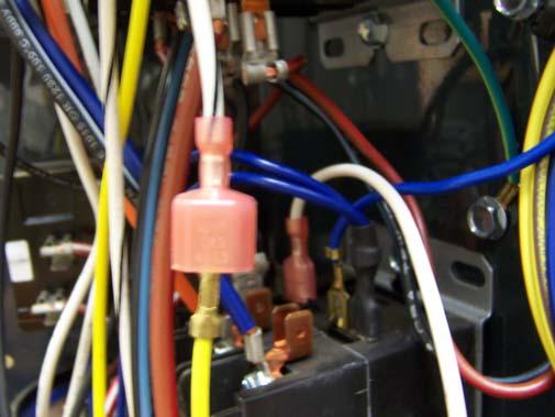
5 Terminate the connecting cable as shown, wire colors will be based upon the cable used, write in for future troubleshooting. Also see EH715 drawing. WF TB3 Function SLT I/F Wire Color 1 R 24 VAC power, hot 1 R 2 W Compressor on 2 W-ON 3 C Common/ground 3 C 4 INT INT (summer, K7) 4 INT 5 X EXT ODT, -17 output 5 X 6 RV Reversing valve, cool 6 RV Pigtail wire blk/wht ODU special power control 7 reset Mounting SLT I/F relay box three HP outdoor unit access panels will need to be removed the corner control box, the corner bottom wiring shield/panel (just above refrigerant lines), and the front louvered panel accessing the reversing valve. See Photo A, this identifies the compartment under the corner control box and seems to be the best location for SLT I/F relay box. Prepare for mounting by drilling screw holes, etc. All the pigtail wires will need to be fed through the vertical panel, then looped back through the same vertical panel into the main control upper section. Photo B shows the mounting completed. Suggestion is to terminate the 7 wires (8-wire stat cable) coming from the SLT control board before actually screwing down the SLT I/F. The above chart and drawing EH715 show these terminal block to terminal block connections. After completing the connections at the SLT I/F board terminal block and the routing of the cable as suggested in the next paragraph, install the plastic cover over the SLT I/F relay box. Photo A Photo B 09/15/ HI111

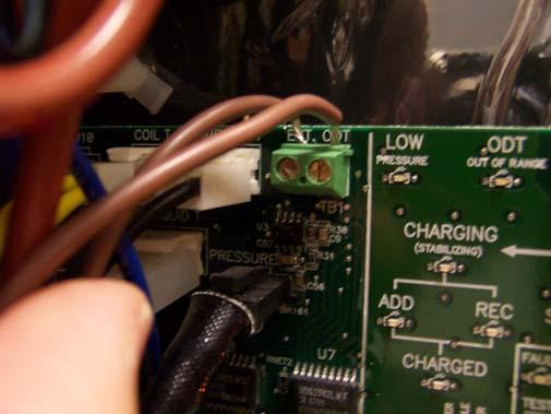
6 Internal wiring connections the pigtail wires from the SLT I/F are terminated at various connection points in the outdoor unit corner control box. At several wiring points an existing wire is actually removed and two wires from the SLT I/F are run in series between the component tab and the wire removed. Use electrical tape over any exposed terminals. The remarks column provides this additional step information. SLT I/F Wire ODU Component Tab ODU Wire Remarks Photo Red Fuse tab Remove red wire from fuse load side C Red/black Red Series wires, connection C Blue Transformer Add the piggyback connector to common (blue Blue existing blue piggyback junction junction) D Orange Yellow* Yellow/green* White Reversing valve, coil junction HI contactor coil LO contactor coil Orange Yellow with orange tracer Add the piggyback connector to existing orange junction Remove yellow with orange tracer from coil tab Series wire connection Remove yellow with black tracer from coil tab White/black Yellow with black tracer Series wire connection G Brown EXT ODU TB Top center unit outdoor board H Brown EXT ODT TB 2-screw TB (no polarity) H *16i only has one contactor, do not use these yellow and yellow/green wires, tape and stow. E F F G Photo C Photo D 09/15/ HI111


7 Photo E Photo F Photo G Photo H 09/15/ HI111
8 Additional Hookup or Special System Equipment Concerns Remotely Located Standby Override Switch On the bottom of the SLT control board is an SB SW tab. Using an external switch between this SB SW tab and a common tab provides the same function as the front override switch. Whichever switch is in the up or override position takes priority. In other words, they both need to be in the down position during cooling. Note: All override switches (front panel and any options) must be in normal or electric position during cooling. Load Control, Other Products or Hardware If there is a need to pass on the utility load control receiver function to other heating equipment, radiant floor boiler, peak interrupter, etc; there is an isolated contact on this control board. Locate tabs COM/EL/SB. In the electric mode there is an isolated contact between COM and EL. This contact is for low voltage only, 1-amp maximum. Note: There may be a 1 or 2 minute delay between this relay contact action and the actual load control receiver. This delay coincides with various blower purge functions. Note: This contact also follows front panel standby switch. 09/15/ HI111
9 Field Setup or Programming Trane 900 Controller there are only two special setups required for this combination system. However, for proper operation, efficiency, and comfort it is important that these two setups be taken care of. ISU 0346 upstage suggest either disabled or 75 minutes ISU 0350 set to 5 F Important This special model has its own programming chip. The unit as received should include version and up. If this is not the case there will be improper functioning of the SLT I/F relays. Warm Air Sensing Control this is active only with temperatures above switchover and if the duct sensor is connected and installed. See the next section, explaining the operation. 0 = 90 4 = 98 Factory set on #3. 1 = 92 5 = = 94 6 = = 96 7 = 104 If the installer/user desires not to use the supply temperature sensing switchover to standby function, simply set the warm air dial switch to #0. Heat Pump Operation/Supply Temperature/Switchover Delay Time As stated on the cover and in the later sequence section, the heat pump run time before checking or sampling the minimum warm air (ST sensor) setting is factory default set at 30 minutes. There is a method of field changing the 30 minutes. This dial switch is purposely inconvenient. The front decal for this specific controller model has an adhesive applied decal to cover the normal temperature/efficiency dial. This dial switch can now be used to change this delay time. The field installer must remove this paste over decal to make the change and replace the cover decal. 0 = 5 4 = 30 Factory set on #4. 1 = 10 5 = 40 2 = 15 6 = 50 3 = 20 7 = 60 WarmFlo Select/ComfortLink II System Combination Sequence Standby (SB) this is controlled or activated by either of the four (can be monitored or determined by the front panel amber mode LED). Utility load control receiver/lmc/blue and blue white wire loop. This is activated in either heat or cool mode, summer or winter, only one LMC contact is needed. The WF controller determines heat/cool and does the proper standby function. WF front panel standby switch SB SW tab switch contact to COM. Heat pump did not bring the temperature up to warm air dial setting. During SB the ODU compressor contactor coils are interrupted. - Option this SB function only interrupts the compressors, the ODU fan will continue during call for cool. Within the I/F SLT box there are two tabs T4 and T5. This is an isolated relay contact which could be used to interrupt any other unwanted electrical circuit during cooling SB. Special feature, this controller at the roomstat heat call and heat pump main contactor turn-on, this controller begins sampling the ST sensor, rolling average for one minute. At turn-on it also begins a 30 minute delay timer. At the end of this delay timer, if the ST average temperature is not greater than the 09/15/ HI111
10 warm air dial switch set point, standby (SB) is initiated and the room thermostat now is controlling the gas furnace. The ST sensor now expects a temperature build up greater than 95 F. Once above 95 F and the controller conditions itself back to electric mode waiting for the next on signal from the heat pump compressor contactor. This standby is initiated by either of the first three methods above, the heat pump is interrupted and the thermostat heat call will go directly to gas furnace. If the system is in cooling, standby (SB) is potentially active and can be initiated from any of the above three. Cooling SB is interrupting the compressor, no gas furnace possibility. Heat/cool this is determined by the heat pump reversing valve orange wire. High or 24VAC = cooling. Reversing valve/tb3-7/rv/tb3-6/rv/orange wire connection Cooling except for load control or standby (SB) function, WF is locked out. Heat pump and furnace blower/air handler do their normal designed cooling functions, WF is basically out of the circuit. Cooling interrupt/tb3-4/int/tb1-4/int/k1 and K4 NO (WF board K7 reverse logic opens) compressor contactor coils and provides option T4 and T5 tabs. Standby (SB): - RESET causes an interrupt of the heat pump 24-volt transformer source thus forcing a heat pump ODU internal reset (10 seconds). Reset/T5/blk/wht/TB1-7/reset/K3 NC opens red wire - X activates a special condition within the heat pump logic board where it forces the logic board to set itself to -17 outdoor temperature. With a -17 F switchover temperature the heat pump logic terminates the contactors and all the thermostat control goes to the gas furnace. X/TB3-5/X/TB1-5/X/K2 NO activates -17 F switchover Furnace blower speeds, etc. the furnace blower and all gas furnace functions are handled by ComfortLink II, there is no connection with WF board. ComfortLink II appears to have adequate blower purge functions to protect or take care of any WarmFlo element concerns. WarmFlo control power the WarmFlo Select board receives its 24-volt source from the outdoor unit transformer. This is via TB3-1 (R) and TB3-3 (COM). 09/15/ HI111
11 Front Panel LED s Operation Indicators - PWR ON indicates good fuse and 24-volt power source from the furnace terminal block. - Mode this LED provides two sets of information: o Off, standby mode (SB) o On, electric heat mode o Pulsing, cooling mode Override Switch the front panel slide switch (very similar to standard DFC) is a direct hardware disabling of any electric mode functions. The room thermostat heat call wire or function is directly controlling the fossil fuel or gas furnace. This function can also be on a remote switch, see previous statement for SBSW tab. WARNING THIS FRONT PANEL MANUAL OVERRIDE SWITCH IS A HARDWARE DIRECT TO GAS FURNACE FUNCTION. THUS THERE ARE NO BLOWER PURGE CYCLES. IF THE ELECTRIC ELEMENTS ARE ON AND HOT WHEN SWITCHING TO OVERRIDE AND IMMEDIATELY ALLOWING THE GAS FURNACE, OVERHEAT ON THE ELECTRIC ELEMENTS AND POTENTIAL ELECTRO-MATE MANUAL RESET IS POSSIBLE. THIS FRONT PANEL OVERRIDE SWITCH SHOULD ONLY BE ACTIVATED WHEN THERE IS NOT A ROOMSTAT HEAT CALL. Note: This switch must be in the normal position during cooling. Sensor Monitor Indicators in addition to using WarmFlo Analyzer or WarmFlo PC software to readout the temperature sensors, there is a built-in go/no-go type monitor visible on the green PWR ON second from the top LED. - If there is detection of miswired or totally inoperative sensor, this LED has a blinking or pulse mode. By checking the pulsing pattern, the appropriate sensor can be identified. - ST sensor - two, 100 ms blinks every second Handheld Analyzer/Laptop Software This test tool and/or software is available for temperature offset, field altering the program chip parameters and setup, and general assistance for troubleshooting. However, for this special version software the factory or setup defaults, read out and controlled are different. Setup Defaults MU TIME 00 OT FUNC DT CAL SB RESET DISABLE ODT SW HP ODT SOT-S TIME 00 OT SPD A 30 SOT-E TIME 00 OT SPD B 20 STG 1 OT DIS 55 ST SPD A 95 STG 2 OT DIS 38 ST SPD B 105 STG 3 OT DIS 36 STG 4 OT DIS 34 09/15/ HI111
12
13
14 Electro Industries, Inc. Limited Product Warranty Effective February 5, 2009 Electro Industries, Inc. warrants to the original owner, at the original installation site, for a period of two (2) years from date of installation, that the product and product parts manufactured by Electro Industries are free from manufacturing defects in materials and workmanship, when used under normal conditions and when such product has not been modified or changed in any manner after leaving the plant of Electro Industries. If any product or product parts manufactured by Electro Industries are found to have manufacturing defects in materials or workmanship, such will be repaired or replaced by Electro Industries. Electro Industries shall have the opportunity to directly, or through its authorized representative, examine and inspect the alleged defective product or product parts. Electro Industries may request that the materials be returned to Electro Industries at the owner s expense for factory inspection. The determination as to whether product or product parts shall be repaired, or in the alternative replaced, shall be made by Electro Industries or its authorized representative. Electro Industries will cover reasonable labor costs to repair defective product or product parts for ninety (90) days after installation. TWENTY YEAR (20) LIMITED WARRANTY ON BOILER ELEMENTS AND VESSELS Electro Industries, Inc. warrants that the boiler elements and vessels of its products are free from defects in materials and workmanship through the twentieth year following date of installation. If any boiler elements or vessels are found to have a manufacturing defect in materials or workmanship, Electro Industries will replace them. TWENTY YEAR (20) LIMITED WARRANTY ON SPIN FIN ELEMENTS Electro Industries, Inc. warrants that the spin fin elements of its products are free from defects in materials and workmanship through the twentieth year following date of installation. If any spin fin elements are found to have a manufacturing defect in materials or workmanship, Electro Industries will replace them. FIVE YEAR (5) LIMITED WARRANTY ON OPEN WIRE ELEMENTS Electro Industries, Inc. warrants that the open wire elements of its products are free from defects in materials and workmanship through the fifth year following date of installation. If any open wire elements are found to have a manufacturing defect in materials or workmanship, Electro Industries will replace them. Page 1 of 2 XX017
15 THESE WARRANTIES DO NOT COVER: 1. Costs for labor for removal and reinstallation of an alleged defective product or product parts, transportation to Electro Industries, and any other materials necessary to perform the exchange, except as stated in this warranty. Replacement material will be invoiced to the distributor in the usual manner and will be subject to adjustment upon verification of defect. 2. Any product that has been damaged as a result of being improperly serviced or operated, including, but not limited to, the following: operated with insufficient water or airflow, allowed to freeze, subjected to flood conditions, subjected to improper voltages or power supplies, operated with airflow or water conditions and/or fuels or additives which cause unusual deposits or corrosion in or on the product, chemical or galvanic erosion, improper maintenance or subject to any other abuse or negligence. 3. Any product that has been damaged as a result of natural disasters, including, but not limited to, the following: lightning, fire, earthquake, hurricanes, tornadoes or floods. 4. Any product that has been damaged as a result of shipment or handling by the freight carrier. It is the receiver s responsibility to claim and process freight damage with the carrier. 5. Any product that has been defaced, abused, or suffered unusual wear and tear as determined by Electro Industries or its authorized representative. 6. Workmanship of any installer of the product. This warranty does not assume any liability of any nature for unsatisfactory performance caused by improper installation. 7. Transportation charges for any replacement part or component, service calls, normal maintenance; replacement of fuses, filters, refrigerant, etc. CONDITIONS AND LIMITATIONS: 1. If at the time of a request for service the original owner cannot provide an original sales receipt or a warranty card registration then the warranty period for the product will have deemed to begin thirty (30) days after the date of manufacture and NOT the date of installation. 2. The product must have been sold and installed by a licensed electrical contractor, a licensed plumbing contractor, or a licensed heating contractor. 3. The application and installation of the product must be in compliance with Electro Industries specifications as stated in the installation and instruction manual, and all state and federal codes and statutes. If not, the warranty will be null and void. 4. The purchaser shall have maintained the product in accordance with the manual that accompanies the unit. Annually, a qualified and licensed contractor must inspect the product to assure it is in proper working condition. 5. All related heating components must be maintained in good operating condition. 6. All lines must be checked to confirm that all condensation drains properly from the unit. 7. Replacement of a product or product part under this limited warranty does not extend the warranty term or period. 8. Replacement product parts are warranted to be free from defects in material and workmanship for ninety (90) days from the date of installation. All exclusions, conditions, and limitations expressed in this warranty apply. 9. Before warranty claims will be honored, Electro Industries shall have the opportunity to directly, or through its authorized representative, examine and inspect the alleged defective product or product parts. Remedies under this warranty are limited to repairing or replacing alleged defective product or product parts. The decision whether to repair or, in the alternative replace, products or product parts shall be made by Electro Industries or its authorized representative. THESE WARRANTIES DO NOT EXTEND TO ANYONE EXCEPT THE ORIGINAL PURCHASER AT RETAIL AND ONLY WHEN THE PRODUCT IS IN THE ORIGINAL INSTALLATION SITE. THE REMEDIES SET FORTH HEREIN ARE EXCLUSIVE. ALL IMPLIED WARRANTIES, INCLUDING WARRANTIES OF MERCHANTABILITY AND FITNESS FOR A PARTICULAR PURPOSE, ARE HEREBY DISCLAIMED WITH RESPECT TO ALL PURCHASERS OR OWNERS. ELECTRO INDUSTRIES, INC. IS NOT BOUND BY PROMISES MADE BY OTHERS BEYOND THE TERMS OF THESE WARRANTIES. FAILURE TO RETURN THE WARRANTY CARD SHALL HAVE NO EFFECT ON THE DISCLAIMER OF THESE IMPLIED WARRANTIES. ALL EXPRESS WARRANTIES SHALL BE LIMITED TO THE DURATION OF THIS EXPRESS LIMITED WARRANTIES SET FORTH HEREIN AND EXCLUDE ANY LIABILITY FOR CONSEQUENTIAL OR INCIDENTAL DAMAGES RESULTING FROM THE BREACH THEREOF. SOME STATES DO NOT ALLOW THE EXCLUSION OR LIMITATION OF INCIDENTAL OR CONSEQUENTIAL DAMAGES, SO THE ABOVE LIMITATIONS OR EXCLUSIONS MAY NOT APPLY. PRODUCTS OR PARTS OF OTHER MANUFACTURERS ATTACHED ARE SPECIFICALLY EXCLUDED FROM THE WARRANTY. THIS WARRANTY GIVES YOU SPECIFIC LEGAL RIGHTS, AND YOU MAY HAVE OTHER RIGHTS WHICH VARY UNDER THE LAWS OF EACH STATE. IF ANY PROVISION OF THIS WARRANTY IS PROHIBITED OR INVALID UNDER APPLICABLE STATE LAW, THAT PROVISION SHALL BE INEFFECTIVE TO THE EXTENT OF THE PROHIBITION OR INVALIDITY WITHOUT INVALIDATING THE REMAINDER OF THE AFFECTED PROVISION OR THE OTHER PROVISIONS OF THIS WARRANTY. Page 2 of 2 XX017
Multiple Boilers Electro TS Series Application EB-C-STG5
 Multiple Boilers Electro TS Series Application EB-C-STG5 Drawings: BC025 BX404 BH504 XX017 Information All Electro-Boilers, except Mini-Boiler, have the same control board (EB5623**). The plug-in control
Installation & Operating Instructions
 THE NEXT GENERATION OF THE INDUSTRY STANDARD PLENUM HEATER Installation & Operating Instructions EM-WU(WD)***D*-SLT Series Communicating Thermostat Systems, specifically Trane ComfortLink and American
BASIC INSTALLATION AND OPERATION MANUAL
 BASIC INSTALLATION AND OPERATION MANUAL EMDI ** *5 * Size H = 8W x 10D L = 8W x 16D kw Stages 10 = 9.6 kw 2 = 2 15 = 14.4 kw 3 = 3 20 = 19.2 kw NOTE: This Duct Heater may have various installation applications.
ELECTRIC MAKE-UP AIR
 ELECTRIC MAKE-UP AIR WITH WARMFLO CONTROLLER EM-WM**3** 15 = 15 kw 20 = 20 kw 11 = 10 kw, 3-phase 5 = Single phase, 5 kw per stage 4 = 3-phase, 3-stage 6 = 3-phase, 3-stage H = 8w x 10d L = 8w x 16d Specific
Installation & Operating Instructions
 THE NEXT GENERATION OF THE INDUSTRY STANDARD PLENUM HEATER Installation & Operating Instructions EM-WU(WD)***D*-SL2 Series Two stage HP Equipment See specification page for model number breakdown and details
Electro Industries Make-Up Air II
 --------------------------------------------------------------------------------------- Installation & Operating Manual ---------------------------------------------------------------------------------------
Installation & Operating Instructions
 THE NEXT GENERATION OF THE INDUSTRY STANDARD PLENUM HEATER Installation & Operating Instructions EM-WU(WD)***S*-SL1 Series One Stage HP or One or Two Stage AC See specification page for model number breakdown
ECM Blower, All Hookups, WarmFlo ST/OT CFM Selection
 Assumptions Electro-HELPS VIII ECM Blower, All Hookups, WarmFlo ST/OT CFM Selection 1. Typically the furnace will be setup for a top (Y2) speed relating to cooling requirement. Installer must determine
Dual Heat System. Universal Furnace Interface Module. Specially Equipped for 2-Speed HP. Controller Portion of Electro-Mate
 WARMFLO Dual Heat System Universal Furnace Interface Module Specially Equipped for 2-Speed HP Controller Portion of Electro-Mate Also accompanying each system is a specific control program chip. This is
WARMFLO COMPATIBLE. Upflow. Number of Stages. This is a single package unit, it contains the WarmFlo II controller with a built-in WF- EZ3.
 WARMFLO COMPATIBLE Upflow EM-WU **+H* Width 5 = 15 8 = 18 Number of Stages kw Size 05 = 5 kw 10 = 10 kw This is a single package unit, it contains the WarmFlo II controller with a built-in WF- EZ3. Requires
Safety & Installation Instructions
 Model 6303 & 6302 Zoned Comfort Control Safety & Installation Instructions READ AND SAVE THESE INSTRUCTIONS 61001212A 6302-6303 Zoned Comfort Control Install.indd 1 TABLE OF CONTENTS SAFETY INSTRUCTIONS..........................................
WMWLB / WMWFM / WTWLB / WTWFM Series Hydronic Heating Unit
 January 2008 WMWLB / WMWFM / WTWLB / WTWFM Series Hydronic Heating Unit Installation Operation Maintenance The units are designed for permanent up flow, counter flow, or horizontal left or right airflow
INSTALLATION & OPERATING INSTRUCTIONS
 ELECTRO-BOILER TS Series INSTALLATION & OPERATING INSTRUCTIONS Model EB-S-13 EB-S-18 EB-S-23 EB-S-27 APPLICATION: This Electro-Boiler series is factory equipped with outlet temperature sensing and a smart
Safety & Installation Instructions
 Model 6203 & 6202 Zoned Comfort Control Safety & Installation Instructions READ AND SAVE THESE INSTRUCTIONS 61001213A 6202-6203 Zoned Comfort Control Install.indd 1 TABLE OF CONTENTS SAFETY INSTRUCTIONS..........................................
Installation Instructions
 P700U -21NHP Base Non -Programmable Thermostats Installation Instructions Designed and Assembled in the USA. US patents: US20060165149 A1, USD578026 SI, US6205041 B1 A14005 Base Non---Programmable Thermostat
Industrial Series. Electric Hot Water Boiler EB-NB Series Installation & Operating Manual
 Industrial Series Electric Hot Water Boiler EB-NB Series Installation & Operating Manual See page 1 Specification Chart for specific model by voltage and kw size. Evaluate utility service/utility transformer
VENSTAR T1070 FAN COIL THERMOSTAT PROGRAMMABLE 2 OR 4 PIPE SYSTEMS OWNER S MANUAL AND INSTALLATION INSTRUCTIONS
 VENSTAR FAN COIL THERMOSTAT FAN COIL THERMOSTAT T1070 NON- PROGRAMMABLE 2 OR 4 PIPE SYSTEMS Remote sensor ready 3 speed fan control Self-prompting adjustment Auto 2-pipe changeover when used with ACC-SENFC
WIRING DIAGRAMS R410A MODELS PAC 2OAC/2OACH CAC OWC PWC
 WIRING DIAGRAMS R410A MODELS 2OAC/2OACH PAC CAC PWC OWC WIRING 02172017 TABLE OF CONTENTS PAGE 2OACH Deluxe Portable Air-cooled Heat Pump Electronic Controller... 2-3 Piping Schematic... 4 Single Phase
be liable for any other loss or damage, whether direct, indirect, incidental or consequential.
 Integrated HydroStat 3200-Plus for Slant Fin Boilers Part No. 48-3200-03 and 48-3200-04 120 VAC Input / 24 VAC Burner Circuit PATENT S. 8.391,708; 7,891,572; 8,844,834; Others Pending INSTALLATION INSTRUCTIONS
ELECTRO-BOILER. Commercial Series. INSTALLATION & OPERATING INSTRUCTIONS Model EB-C* Series
 ELECTRO-BOILER Commercial Series INSTALLATION & OPERATING INSTRUCTIONS Model EB-C* Series LOCATE EXACT NUMBER ON NAMEPLATE, LOCATE LINE ITEM ON PAGE 1 APPLICATION: This Electro-Boiler is factory equipped
INSTALLATION INSTRUCTIONS and OPERATING MANUAL. *Aquastat is a registered trademark of Honeywell International, Inc.
 MODEL 3200-Plus Temp Limit / LWCO Control with Thermal Targeting for Water Boilers 120 VAC Input / 24 VAC Burner Circuit PATENT. 8,931,708; 8,844,834; 7,891,572; others pending INSTALLATION INSTRUCTIONS
VENSTAR T1075 FAN COIL THERMOSTAT 7 DAY PROGRAMMABLE 2 OR 4 PIPE SYSTEMS OWNER S MANUAL AND INSTALLATION INSTRUCTIONS
 VENSTAR FAN COIL THERMOSTAT FAN COIL THERMOSTAT T1075 7 DAY PROGRAMMABLE 2 OR 4 PIPE SYSTEMS 3 Occupied, 1 Unoccupied Override capable 3 speed fan control Auto 2-pipe changeover when used with accessory
INSTALLATION INSTRUCTIONS and OPERATING MANUAL. *Aquastat is a registered trademark of Honeywell International, Inc.
 MODEL 3200-Plus Temp Limit / LWCO Control with Thermal Targeting for Water Boilers 120 VAC Input / 24 VAC Burner Circuit PATENT. 7,891,572 INSTALLATION INSTRUCTIONS and OPERATING MANUAL Saves Fuel Features
Installation, Operation & Service Manual
 Installation, Operation & Service Manual WARNING Improper installation, adjustment, alteration, service or maintenance can result in death, injury or property damage. Read the Installation, Operation and
Industrial Series. Electric Hot Water Boiler EB-NB Series Installation & Operating Manual
 Industrial Series Electric Hot Water Boiler EB-NB Series Installation & Operating Manual See page 1 Specification Chart for specific model by voltage and kw size. Evaluate utility service/utility transformer
ELECTRO-BOILER Commercial Series
 ELECTRO-BOILER Commercial Series INSTALLATION & OPERATING INSTRUCTIONS Model EB-CX Series APPLICATION: This Electro-Boiler is factory equipped with WarmFlo smart controller. WarmFlo automatically regulates
Carrier NON-PROGRAMMABLE DIGITAL THERMOSTAT. Dual Setpoint Thermoglow Backlight No Batteries Required Auto Changeover Locking Keypad
 Carrier Heating & Cooling TSTATCCNB00 NON-PROGRAMMABLE DIGITAL THERMOSTAT USER INFORMATION MANUAL FOR THE OPERATION AND MAINTENANCE OF YOUR NEW THERMOSTAT NON-PROGRAMMABLE DIGITAL THERMOSTAT AUTO 74 Dual
Installation and Operations Manual
 Installation and Operations Manual H-IM-LLC February 2018 Part No. 25092501 Replaces H-IM-LLC (01/2014) Lead Lag Control System Table of Contents General Safety Information 2 Inspection 2 Warranty Statement
Installation Instructions
 EZXCAB Sizes 016 and 020 High Efficiency Air Filtration System Installation Instructions JAN High Efficiency Air Filtration System Fig. 1 - EZXCAB C04001 NOTE: Read the entire instruction manual before
INSTALLATION & OPERATION MANUAL
 INSTALLATION & OPERATION MANUAL Model TME- * * Balance of model number is determined by customer specifi ed limits and Setbacks. AUTOMATIC SETBACK THERMOSTAT LIGHT SENSING OR CONTACT CLOSURE FOR LOW VOLTAGE
FOR EASY, FAST INSTALLATION AND FOR RESULTS
 Page 1 INSTALLATION & OPERATING INSTRUCTIONS FOR FEDERAL FLOOR FURNACE OFB-100 AND OFB100L UNPACK SHIPMENT CAREFULLY AND INSPECT FOR DAMAGE. ALL GOODS ARE CAREFULLY MANUFACTURED, INSPECTED, CHECKED, AND
Programmable Digital Thermostat
 OWNER'S MANUAL P/N P474-2150 1 For All Programmable Digital Thermostat Mo TOTALINE 72 74 COOL AUTO HEAT 70 Optional Locking Cover Meets California Title 24 Dual Setpoint 5+1+1 Day Programmable 3 Occupied,
Installation instructions for Plenum-mounted add-on electric heaters MODEL TU. MARCH 2011 version 7
 Installation instructions for Plenum-mounted add-on electric heaters MODEL TU MARCH 2011 version 7 THERMOLEC PLENUM HEATER MODEL TU BEFORE YOU START -GENERAL SAFETY AND INSTALLATION PRECAUTIONS Please
First Year Limited Warranty for Residential Use Condensing Water Boilers (Includes Heat Exchanger and Component Parts)
") THIS GIVES THE ORIGINAL PURCHASER ONLY SPECIFIC LEGAL RIGHTS AND YOU MAY ALSO HAVE OTHER LEGAL RIGHTS WHICH VARY FROM STATE-TO-STATE AND -TO- Our Warranty By this warranty statement ( Limited Warranty
THIS GIVES THE ORIGINAL PURCHASER ONLY SPECIFIC LEGAL RIGHTS AND YOU MAY ALSO HAVE OTHER LEGAL RIGHTS WHICH VARY FROM STATE-TO-STATE AND -TO- Our Warranty By this warranty statement ( Limited Warranty
CONDENSING WATER BOILERS. (Models VLT , Q VX ,
 Our Warranty By this warranty statement ( Limited Warranty ), ECR International, Inc. ( ECR ) issues limited warranties from the date of installation of the applicable Dunkirk Boiler ( Boiler ) to the
INSTALLATION INSTRUCTIONS and OPERATING MANUAL. *Aquastat is a registered trademark of Honeywell International, Inc.
 MODEL 3200-Plus Temp Limit / LWCO Control with Thermal Targeting for Water Boilers 120 VAC Input / 24 VAC Burner Circuit PATENT. 8,931,708; 8,844,834; 7,891,572; others pending INSTALLATION INSTRUCTIONS
MODEL TSTATBBPB101 PROGRAMMABLE DIGITAL THERMOSTAT. Heat Pump & Heat Cool. Meets California Title 24 Residential USERS INFORMATION MANUAL
 USERS INFORMATION MANUAL Heating & Cooling Systems L TSTATBBPB101 PROGRAMMABLE DIGITAL THERMOSTAT NOTE TO INSTALLER: This manual must be left with the equipment user. AUTO Heat Pump & Heat Cool Dual Setpoint
ELECTRO-BOILER. Midsize INSTALLATION & OPERATING INSTRUCTIONS
 ELECTRO-BOILER Midsize INSTALLATION & OPERATING INSTRUCTIONS Model EB-MO-10 EB-MO-15 EB-MO-20 APPLICATION: This Electro-Boiler is factory equipped with WarmFlo smart controller. WarmFlo automatically regulates
DIGITAL STEEL FIRE & SECURITY
 Models 2111-2115 DIGITAL STEEL FIRE & SECURITY Read this manual carefully and never store it inside the safe! Digital Steel Fire & Security Safe Models 2111-2115 PACKAGE CONTENTS 1 Digital Steel Fire &
A complete product line to fi t all your application needs GENERAL PRODUCT FEATURES
 Electro-HELPS I PLENUM HEATERS A complete product line to fi t all your application needs The Electro-Mate has been heating America s homes and businesses since 1979. We take pride in our craftsmanship
1 For All Programmable Digital Thermostat
 OWNER'S MANUAL P/N P374-2300FM 1 For All Programmable Digital Thermostat Am OFF OVERRIDE Meets California Title 24 unts flush to the wall 7 Day Programmable 3 Occupied, 1 Unoccupied Auto-Changeover Large,
Providing Comfort Through Efficient Energy Solutions PRICE BOOK (USD) - LIST EFFECTIVE JUNE 1,
 - LIST EFFECTIVE JUNE 1,") Providing Comfort Through Efficient Energy Solutions PRICE BOOK (USD) - LIST EFFECTIVE JUNE 1, 2018 2018 www.electromn.com sales@electromn.com PLENUM HEATER WARMFLO SELECT SERIES Our all-in-one plenum
Providing Comfort Through Efficient Energy Solutions PRICE BOOK (USD) - LIST EFFECTIVE JUNE 1, 2018 2018 www.electromn.com sales@electromn.com PLENUM HEATER WARMFLO SELECT SERIES Our all-in-one plenum
DIGITAL STEEL FIRE & SECURITY
 Models 2111-2115 DIGITAL STEEL FIRE & SECURITY Read this manual carefully and never store it inside the safe! Digital Steel Fire & Security Safe Models 2111-2115 PACKAGE CONTENTS 1 Digital Steel Fire &
FLCH4R Garage and Utility Electric Heater
 FLCH4R Garage and Utility Electric Heater Installation, Operation & Maintenance Instructions Model No. Volts Amps Watts BTU/HR Phase High Low High Low High Low Min Fuse Size* FLCH4R 208 17.3 8.66 3600
Installation and Owner Man u al
 T H R E E P H A S E Evaporator Fan Control System Installation and Owner Man u al WARNING The installation of this device should be done only by competent personnel, experienced in electrical wiring, and
Model 8142 and 8142NC Fresh Air Ventilator Installation and Operating Instructions
 Model 8142 and 8142NC Fresh Air Ventilator Installation and Operating Instructions MODEL 8142 FRESH AIR ILATOR MODEL 8142NC FRESH AIR ILATOR OUTLET COLLAR MOUNTING BRACKET ILATION CONTROLLER OUTLET COLLAR
1 For All Programmable or Non-Programmable. Digital Thermostat. Meets Residential California Title 24
 OWNER'S MANUAL P/N P374-1000FM 1 For All Programmable or Non-Programmable Switchable Digital Thermostat 72 74 Am AUTO 70 Mounts Flush to the Wall 1 Day Programmable or Non-Programmable 4 Time Periods per
Whirlpool Bathtub Model Number: MT618
 INSTALLATION AND OWNER'S MANUAL Whirlpool Bathtub Model Number: MT618 Please carefully read these instructions before you begin to install the products. 07/11 Rev A P/N:100056-03 Thank you for purchasing
Spa Control System OWNER S MANUAL
 LIMITED WARRANTY ONE YEAR LIMITED WARRANTY: UNITED SPAS, INC. warrants, to the original purchaser, the Spa Equipment against defects in materials or workmanship for a period of one year from date of purchase.
INSTALLATION INSTRUCTIONS
 INSTALLATION INSTRUCTIONS FOR AQUECOIL HYDRONIC HEATING UNITS GENERAL INFORMATION The AQUECOIL Hydronic Heating Unit is offered in many different capacities and physical configurations in order to match
IAQ Series. Bosch IAQ Photo Catalytic Oxidizer (PCO) Residential Application. Installation Manual and Owner s Guide
 Residential Application. Installation Manual and Owner s Guide") Installation Manual and Owner s Guide IAQ Series Bosch IAQ Photo Catalytic Oxidizer (PCO) Residential Application PCOB-09012-0--A - 9" PCO BULB PCOB-14024-0--A - 14" PCO BULB 67202220344 Revised 07-12
Installation Manual and Owner s Guide IAQ Series Bosch IAQ Photo Catalytic Oxidizer (PCO) Residential Application PCOB-09012-0--A - 9" PCO BULB PCOB-14024-0--A - 14" PCO BULB 67202220344 Revised 07-12
INSTALLATION, OPERATION AND MAINTENANCE
 INLINE HEATER INSTALLATION, OPERATION AND MAINTENANCE MODELS: ILS SERIES 1.5kW 120V SINGLE PHASE BEFORE YOU BEGIN CHECK ALL ELECTRICAL CONNECTIONS TO ALL COMPONENTS WITHIN THE HEATER FOR TIGHTNESS. CONNECTIONS
Three Phase Simplex. Installation (937) Installation Instructions and Operation/Troubleshooting Manual. Installation of Floats.
 Installation Instructions and Operation/Troubleshooting Manual. Installation of Floats.") Three Phase Simplex Installation Instructions and Operation/Troubleshooting Manual This control panel must be installed and serviced by a licensed electrician in accordance with the National Electric Code
Three Phase Simplex Installation Instructions and Operation/Troubleshooting Manual This control panel must be installed and serviced by a licensed electrician in accordance with the National Electric Code
Non-Programmable Digital Thermostat
 OWNER'S MANUAL MODEL P474-0140 Non-Programmable Digital Thermostat HEAT PUMP THERMOSTAT 2 HEAT, 1 COOL emergency aux. heat normal energy save Fan On Fan Auto Millivolt Compatible Battery or System Powered
I2:00 Mo MODEL TSTATBBPB501 PROGRAMMABLE DIGITAL THERMOSTAT. Heat Pump & Heat Cool. Meets California Title 24 Residential USERS INFORMATION MANUAL
 USERS INFORMATION MANUAL Heating & Cooling Systems L TSTATBBPB501 PROGRAMMABLE DIGITAL THERMOSTAT NOTE TO INSTALLER: This manual must be left with the equipment user. Mo 72 74 AUTO HEAT 70 Heat Pump &
MODEL HS115-3, HS115-4 & HS115-5 WIRING DIAGRAM ADDENDUM
 TJERNLUND PRODUCTS, INC. 1601 Ninth Street White Bear Lake, MN 55110-6794 PHONE (800) 255-4208 (651) 426-2993 FAX (651) 426-9547 Visit our web site www.tjernlund.com MODEL HS115-3, HS115-4 & HS115-5 WIRING
Installation & Operating Instructions
 Installation & Operating Instructions WF-DHEMK Application This conversion kit is for use in applications with air conditioning or single stage heat pump. If interfacing with a 2-stage heat pump, order
REFRIGERATED DROP-INS (2-6)FT-DI Installation and Operating Manual
FT-DI Installation and Operating Manual") REFRIGERATED DROP-INS (2-6)FT-DI Installation and Operating Manual For service information call 800-544-3057 Please have the following information available before calling. Information can be found on
REFRIGERATED DROP-INS (2-6)FT-DI Installation and Operating Manual For service information call 800-544-3057 Please have the following information available before calling. Information can be found on
Sentry LIQUID LEVEL CONTROLLER MODEL 120 OPERATING MANUAL.
 Sentry LIQUID LEVEL CONTROLLER MODEL 120 OPERATING MANUAL www.aquaticsentry.com TABLE OF CONTENTS 1. SAFETY PRECAUTIONS... 3 2. APPLICATION... 3 2.1 HIGH AND LOW LEVEL ALARM 2.2 PUMP DOWN CONTROLLER 2.3
INSTALLATION INSTRUCTIONS and OPERATING MANUAL. *Aquastat is a registered trademark of Honeywell International, Inc.
 MODEL 3150 Combination Low Water Cut-Off & Universal Temperature Limit Control for Oil-Fired Boilers 120 VAC Operating Voltage PATENT S. 7,891,572; 8,931,708 INSTALLATION INSTRUCTIONS and OPERATING MANUAL
IW-25-2 Dehumidifier Installation & Operations. Manual
 IW-25-2 Dehumidifier Installation & Operations Installation and Operation Manual Manual IW-25-1 Dehumidifier Please Read and Save These Instructions Please Read and Save These Instructions Innovative Dehumidifier
SPA BLOWER OWNER'S MANUAL XXXX, XXXX, XXXX, XXXX, XXXX, XXXX fax
 SPA BLOWER OWNER'S MANUAL 80015-XXXX, 80016-XXXX, 80017-XXXX, 80018-XXXX, 80019-XXXX, 80020-XXXX fax 888.610.3839 2015 323300-015 6/15 THIS PAGE INTENTIONALLY LEFT BLANK. 2 Operating Instructions and Parts
Installation and Operation Manual
 Model 8120X Digital Ventilation Controller CODE MIN/ HR Installation and Operation Manual TABLE OF CONTENTS WARNINGS AND CAUTIONS Warnings and Cautions... 3 Package Contents... 4 Specifications.... 4 Mounting
Ion Endeavor Pump Controller Digital Level Control with Pump Alternation and High Water Alarm
 Ion Endeavor Controller Digital Level Control with Alternation Page 1 of 8 General Overview The Ion Endeavor is a pump controller that senses a water level of up to 72", has a configurable water level/pump
Operation Manual. Instructions for Installation, Operation & Maintenance. PortaPac 5-, 8 and 10-ton Portable Air Conditioners
 Operation Manual PortaPac 5-, 8 and 10-ton Portable Air Conditioners A AirPac, Incorporated AirPac Technology Park 888 Shenandoah Shores Road Front Royal, Virginia 22630 U.S.A. Toll Free 888-324-7722 Web:
INSTALLATION INSTRUCTIONS and OPERATING MANUAL. *Aquastat is a registered trademark of Honeywell International, Inc.
 MODEL 3250-Plus Temp Limit / LWCO Control with Thermal Targeting for Water Boilers 120 VAC Operating Voltage PATENT. 8,931,708; 8,844,834; 7,891,572; others pending INSTALLATION INSTRUCTIONS and OPERATING
Model 8140 & 8141 Fresh Air Ventilator Installation and Operations Manual
 Model 8140 & 8141 Fresh Air Ventilator Installation and Operations Manual FILTER COVER VENTILATION CONTROLLER INLET COLLAR OUTLET COLLAR SAFETY INSTRUCTIONS WARNING 1. 120 Volts may cause serious injury
1 For All Programmable Digital Thermostat. Meets Residential California Title 24
 OWNER'S MANUAL P/N P374-1100FM 1 For All Programmable Digital Thermostat 72 74 Am I2:00 AUTO 70 unts Flush to the Wall 7 Day Programmable 4 Time Periods per Day Auto Changeover Large, Easy To Read Display
Indoor Unit (IDU) Installation & Operating Instructions Model: NC-FE-***
 Installation & Operating Instructions Model: NC-FE-***") Indoor Unit (IDU) Installation & Operating Instructions Model: NC-FE-*** Application Air source heat pump with hydronic (or warm water) and chilled water output Equipped with Electro-Boiler boost and Backup
Indoor Unit (IDU) Installation & Operating Instructions Model: NC-FE-*** Application Air source heat pump with hydronic (or warm water) and chilled water output Equipped with Electro-Boiler boost and Backup
B SERIES ELECTRIC FURNACE
 MISSISSAUGA, ONTARIO L5T 1H9 TEL.: 905-670-2500 FAX: 905-795-8311 CUSTOMER SERVICE TEL.: 1-888-882-7626 B SERIES ELECTRIC FURNACE! WARNING 1. The user MUST contact a specialized contractor when a failure
DUST FREE CARBON Whole House Air Purifier
 DUST FREE CARBON Whole House Air Purifier Installation & Operation Manual This manual covers the following model: DF CARBON 14" - #13052 GENERAL This device is designed to be installed into an existing
Easy installation in both new construction and retrofit. ZB90C ZB110C X2 Multi-Speed Ventilation Fan INSTALLATION GUIDE
 READ AND SAVE THESE INSTRUCTIONS Installer: leave this guide with homeowner. Register your product online at www.broan.ca/register.asp. ZB90C ZB0C X Multi-Speed Ventilation Fan INSTALLATION GUIDE Easy
7-Day. Digital Thermostat. residential. & 2-cool
 Digital Thermostat residential THERMOSTAT T1100FS 7-Day PROGRAMMABLE up to 2-heat & 2-cool PUMP Control up to 2 Heat & 2 Cool Stages 7-Day Programmable 4 Settings/Day Auto Changeover 5 minute Built-In
AG Series Electric Heaters
 AG Series Electric Heaters Auxiliary Electric Heat Installation, Operation & Maintenance Instructions 97B0005N04 Table of Contents Overview 3 Vertical Upflow or Downflow Installation - Internal 3 Vertical
Ion Genesis II Pump Controller Digital Level Control with Pump Alternation and High Water Alarm
 Page 1 of 8 General Overview Thank you for purchasing an Ion Genesis controller. Take the time to read the instructions carefully before using this appliance. We strongly recommend that you keep this instruction
Electro-HELPS XV ELECTRO-BOILER SPECIFICATIONS. A complete product line to fi t all your application needs. Made in USA
 Electro-HELPS XV Made in USA ELECTRO-BOILER SPECIFICATIONS A complete product line to fi t all your application needs The Electro-Boiler has been heating America s homes and businesses since 980. We take
Thermostat Remote Control & Receiver
 OWNER S MANUAL P/N 33CSIRRCVR-01 Thermostat Remote Control & Receiver Allows remote control operation of basic thermostat functions Unique Warmer & Cooler commands Compatible with thermostat models: 33CS450-01,
OPERATION AND MAINTENANCE INSTRUCTIONS FOR ROOF TOP HEAT PUMPS AND CEILING PLENUMS
 OPERATION AND MAINTENANCE INSTRUCTIONS FOR ROOF TOP HEAT PUMPS AND CEILING PLENUMS TABLE OF CONTENTS I. General Information.................................................. 2 II. Standard Ceiling Plenum
MaxLite LED Vapor Tight Linear Fixture
 General Safety Information To reduce the risk of death, personal injury or property damage from fire, electric shock, falling parts, cuts/abrasions, and other hazards read all warnings and instructions
5+2 DAY. Digital Thermostat. residential. & 1-cool. up to 2-heat PROGRAMMABLE THERMOSTAT. Venstar Inc. 05/08
 Digital Thermostat residential THERMOSTAT 5+2 DAY PROGRAMMABLE up to 2-heat & 1-cool HEAT PUMP Stages: 2-Heat, 1-Cool Battery or System Powered Auxiliary Heat Indicator Back-Lit Digital Display Fahrenheit
OPERATION & INSTALLATION MANUAL
 OPERATION & INSTALLATION MANUAL Model: SIO 14 & SIO 18 Electric Tankless Hot Water Generators Table of Contents SAFETY INFORMATION... 1 INTRODUCTION... 2 Unit Operation:... 2 Unit Freezing:... 3 Maintenance:...
DUAL VOLTAGE REFRIGERATORS 220/240 VOLTS AC AND 12/24 VOLTS DC INSTALLATION AND OWNER S MANUAL
 DUAL VOLTAGE REFRIGERATORS 220/240 VOLTS AC AND 12/24 VOLTS DC INSTALLATION AND OWNER S MANUAL Service Information If service or parts are required, contact the nearest Norcold Service Center. To find
INSTALLATION INSTRUCTIONS
 INSTALLATION INSTRUCTIONS Keep these instructions with the boiler at all times. BOYERTOWN FURNACE CO. PO Box 100 BOYERTOWN, PA 19512 1-610-369-1450 www.boyertownfurnace.com 5-25-12 2 Danger Warning Caution
Operation Manual SCT14B and SCT18B. Inspection. 3 General Description. 3 General Requirements. 3 Standard Features.
 Spot Cooling Systems, Inc. 120 Century Drive Suite 00 Carrollton, TX 7006 00-6-776 Operation Manual SCT1B and SCT1B Warning! Improper installation, adjustment, alteration, service, or maintenance can cause
CT2700 An Electronic Round Programmable Thermostat
 CT2700 An Electronic Round Programmable Thermostat USER S GUIDE MERCURY SWITCH TYPICAL LOCATION OF A MERCURY SWITCH IN A THERMOSTAT M064 RECYCLING THERMOSTAT If this thermostat is replacing a control that
Henny Penny Island Warmer Model HMI-103 Model HMI-105 TECHNICAL MANUAL
 Henny Penny Island Warmer Model HMI-103 Model HMI-105 TECHNICAL MANUAL THIS PAGE INTENTIONALLY LEFT BLANK. Section TABLE OF CONTENTS Page Section 1. TROUBLESHOOTING... 1-1 1-1. Introduction... 1-1 1-2.
Owner s Manual. Digital Thermostat. Heat/Cool & Heat Pump 7-Day Programmable S1-THEM22P7S COMMERCIAL. Model HVAC SERVICE PARTS
 Owner s Manual Model COMMERCIAL TM BACKLIT DISPLAY HVAC SERVICE PARTS Heat/Cool & Heat Pump 7-Day Programmable Digital Thermostat Use with most Heat Pump Systems: 2-Heat, 2-Cool Stages: 2-Heat, 2-Cool
INSTRUCTIONS! DO NOT DISCARD!
 INSTRUCTIONS! DO NOT DISCARD! CAUTION! Do NOT install where injury might occur due to Moving parts, Sharp corners, Hot surfaces or electrical components dcn0620 Page 1 of 12 INSTALLATION INSTRUCTIONS CAUTION
Installation Instructions PP-AS20 Anti-Scale System
 Installation Instructions PP-AS20 Anti-Scale System THIS UNIT MUST BE INSTALLED BY A LICENSED PLUMBER TO VALIDATE THE WARRANTY. COMPONENTS PP-AS20 Filter Housing PP-AS20R Filter Cartridge Installation
BIONAIRE HEATER. Instruction Leaflet. pure indoor living MODEL: BCH4130. Read instructions before operating. Retain for future reference.
 pure indoor living BIONAIRE HEATER MODEL: BCH4130 Instruction Leaflet Read instructions before operating. Retain for future reference. Questions? Comments? Call 1-800-253-2764 in North America. PLEASE
Radiant Thermostat 519
 106103_dl_02 Radiant Thermostat 519 Installation & Operation Manual Introduction The Radiant Thermostat 519 accurately controls the room and/or floor temperature for a hydronic heating zone using Pulse
Installation Manual. Expansion Module 0100 Version 1.0 EXP HBX Control Systems Inc.
 Installation Manual 000 Version.0 EXP-000 HBX Control s Inc. Control s Inc. HBX EXP 000 Version.0 HBX EXP-000 EXPANSION MODULE INTRODUCTION The EXP-000 is designed to be integrated with the HBX CPU-000
INSTALLATION AND OPERATING MANUAL
 INSTALLATION AND OPERATING MANUAL Salad Bars Olive Bars Food Prep Cases Refrigerated Cases with Air-Over Displays Refrigerated Cases with Coppered Cold Well Displays Cases with Under-Counter Refrigerators
14+ SEER R-410a AIR CONDITIONERS. Aluminum Coil Series. Efficiencies up to 14+ SEER/12 EER. Nominal Sizes Ton. Capacities 16.
 14+ SEER R-410a Coil Company, L.P AIR CONDITIONERS UNITED STATES PATENT #D557,394S #D557,395S R-410A Aluminum Coil Series Efficiencies up to 14+ SEER/12 EER Nominal Sizes 1.5-5 Ton Capacities 16.6 to 56
Henny Penny Island Warmer Model HMI-103 Model HMI-105 TECHNICAL MANUAL
 Henny Penny Island Warmer Model HMI-103 Model HMI-105 TECHNICAL MANUAL Section TABLE OF CONTENTS Page Section 1. TROUBLESHOOTING... 1-1 1-1. Introduction... 1-1 1-2. Safety... 1-1 1-3. Troubleshooting...
Safety, Installation, and Operation Manual
 Automatic Steam Humidifier Control Safety, Installation, and Operation Manual READ COMPLETE INSTALLATION INSTRUCTIONS BEFORE STARTING. WARNING This product must be installed by a qualified heating and
TC --- NHP, TC --- NAC Comfort Series Non---Programmable Thermostat. Owner s Manual
 TC --- NHP, TC --- NAC Comfort Series Non---Programmable Thermostat Owner s Manual YOU WILL LOVE THIS THERMOSTAT. This Comfortt non -programmable thermostat is an easy to use model that provides the most
ThermoSaver TM Hot Gas Defrost System
 PRODUCT DATA, APPLICATION & INSTALLATION GUIDE Supplement to Condensing Unit Installation and Maintenance Manual Bulletin B40-THERM-PDI-14 1069132 ThermoSaver TM Hot Gas Defrost System For use on select
ELECTRIC FIREPLACE OWNER S MANUAL
 ELECTRIC FIREPLACE OWNER S MANUAL MODELS EL1346C 4001358 WARNING: If the information in this manual is not followed exactly, a fire or electrical shock may result causing property damage, personal injury
FE1 Series Ventilation Fans 2007 Soleus Air International. Soleus Air Ultra Quiet Ventilation Fan
 Soleus Air Ultra Quiet Ventilation Fan Model No: FE1-05 / FE1-07 / FE1-09 / FE1-11 50 CFM / 70 CFM / 90 CFM / 110 CFM Operating Instructions FE1-05-01 FE1-07-01 FE1-09-01 FE1-11-01 ####### 3092716 FE1