Dual Heat System. Universal Furnace Interface Module. Specially Equipped for 2-Speed HP. Controller Portion of Electro-Mate
|
|
|
- Marian Harris
- 6 years ago
- Views:
Transcription
1 WARMFLO Dual Heat System Universal Furnace Interface Module Specially Equipped for 2-Speed HP Controller Portion of Electro-Mate Also accompanying each system is a specific control program chip. This is typically part of ordering information and should be listed on packing slip. A listing of these chip codes is in the controller setup or programming sections of this document. WarmFlo/Electro-Mate EM-WU*****/EM-WD***** mechanical information companion manual EI703/EI707. Also the WarmFlo control board must be the latest version with 10-pin connector, chip code version 2.30 or higher, and the latest sensors with E identification band. Model WF-HP2 B Must use chip 2.02 or higher. This universal interface module is equipped to handle two types of room thermostats. The installation and setup information is significantly different, the page shown can assist in locating the information relating to the type of thermostat you intend to use. Manufacturer multi-wire HP room thermostat 6-8 Conventional heat/cool, 2H/2C room thermostat 9-11 NOTE 1: With the upgraded revision B product, the conventional 2H/2C roomstat may now be the best choice see pages 5, 9, 12, and 19. NOTE 2: Also review page 19, Blower Speed Operation. Factory default is now set at B. NOTE 3: This interface does not apply to Bryant Evolution or Carrier Infinity. NOTE 4: If there is a less than ideal combination of WF+/EZ-Mate with WF-HP2, see page 20 for setup procedure. Drawings: HH210 HH211B HD320 XX017 08/16/2011 HI210B
2 TABLE OF CONTENTS INTRODUCTION 1 INSTALLATION REQUIREMENTS 2 MECHANICAL INSTALLATION 2 EM-WU***** Electro-Mate Upflow Application 2 EM-WU***** EM-WD***** Electro-Mate Horizontal Application 2 EM-WD***** Electro-Mate Downflow Application 3 WIRING INSTALLATION 4 High Voltage 4 WarmFlo Sensors 4 Outdoor Sensor (OT) 4 Warm Air Supply Sensor (ST) 4 HP Manufacturers Multi-Wire Stat 6 WF-HP2 Setup 8 Conventional 2H/2C Thermostat 9 WF-HP2 Setup 11 Standard Heat/Cool (4-Wire) Thermostat 12 WarmFlo Controller Setup or Programming 13 HPDH, HPDF, HPEL Chip Code Selection 13 OPERATION INDICATORS 16 HANDHELD ANALYZER/LAPTOP SOFTWARE 18 SPECIAL APPLICATION/INSTALLATION 18 Heating, Blower Speed Control 18 1 HEAT/2 HEAT 19 WARMFLO STAT OVERRIDE TIMER (SOT) 20 USING EZ-MATE OR WF+ BOARD 20 TROUBLESHOOTING 22 OPERATIONAL INFORMATION 23 HOOKUP DRAWING WARMFLO INFORMATION WARRANTY Page HH210 HH211B HD320 XX017 08/16/2011 HI210B
3 INTRODUCTION Prior to installation we recommend that the installer verify the system application represents air source heat pump (probably 2-speed)/Electro-Mate plenum heater/standby or gas furnace. The program code chip for the Electro-Mate WarmFlo controller will be either HPDH or HPDF. If your application does not include this combination, do not use this WF-HP2 interface module or this installation manual. Consult factory for other models relating to total electric or air handlers (EM-WE series, WF-DH*** kits, etc.). EM-WU***** WarmFlo/Electro-Mate upflow ranging from 10 kw to 25 kw. Can be installed in upflow applications only. EM-WD***** WarmFlo/Electro-Mate downflow ranging from 10 kw to 25 kw. Can be installed in downflow and horizontal applications. Caution, Heat Pump Application: Depending upon mechanical positioning and airflow, in all cases the electric element, Electro-Mate, unit must be on the supply or warm side of the HP refrigerant coil. First-time or non-routine user before attempting installation or setup, suggest studying the last section of this manual, operational information and terminology definitions. Also if you have not attended a WarmFlo training session, it is strongly advised. With this package is a WarmFlo information document, HD320, which we strongly recommend you take time to read and call factory for questions and further information. This WF-HP2 interface module basically ties together all the low voltage control wiring and interfaces directly with the Electro-Mate/WarmFlo plenum heater and utility load control receiver. It is a universal controller in the sense that it has provisions for all known 2-speed heat pump manufacturers products (except Bryant/Carrier Evolution/Infinity), can use various room thermostats, and can actually be a replacement for the WF-LGR4 or for single speed HP interface module. The control board has several setup peg jumpers, if these are not correctly set in relationship to the components within the system, malfunction and unsatisfactory operation will result. In some cases there s a built-in detection from this wiring and the controller pulses the EL mode LED to indicate incorrect setup (pulsing amber LED). Installer must carefully work through the hookup, also see page 22. The heat pump manufacturers fossil fuel kit or any other controllers relating to manufacturers instructions for dual fuel are not needed and should not be used. This controller works directly with the basic outdoor HP unit and gas furnace wiring terminal block. As stated on the cover, there are major instruction sections relating to either multi-wire heat pump stat or conventional heat/cool stat. The basic and very generic heat/cool 4-wire stat can actually be used for all functions of this system including 2-speed heat pump. With a basic H/C stat (1H/1C), the high speed cooling within the heat pump is activated from three setup options, refer to page 12 emergency switch or emergency timeout (SOT). **Installation Notice - Upon installation it is necessary that all the components of the heating system are in place and functional. This controller is designed to operate the complete heating system - heat pump, backup furnace (gas or oil), Electro-Mate, room thermostat, WF outdoor sensor, etc. If one of these components is missing or not initially installed, improper performance of WarmFlo and the system may be experienced. In other words, if the gas furnace doesn t exist, LP tank not yet installed or filled, and the WarmFlo is operating on a cold day; do not be disappointed if there is no heat. Warranty/Checkout with the Electro-Mate is a warranty certification and checkout procedure. This must be completed and returned for warranty coverage. 08/16/ HI210B
4 INSTALLATION REQUIREMENTS 1. All installation work must be performed by trained, qualified contractors or technicians. Electro Industries, Inc., sponsors installation and service schools to assist the installer. Visit our web site at electromn.com for upcoming service schools. 2. All electrical wiring must be in accordance with National Electric Code and local electric codes, ordinances, and regulations. 3. Observe electric polarity and wiring colors. Failure to observe could cause electric shock and/or damage to the equipment. 4. This unit can only be used for its intended design as described in this manual. Any internal wiring changes, modifications to the circuit board, modifications or bypass of any controls, or installation practices not according to the details of this manual will void the product warranty, the ARL certification label, and manufacturer product liability. Electro Industries, Inc., cannot be held responsible for field modifications, incorrect installations, and conditions which may bypass or compromise the built-in safety features and controls. 5. The only approved installation for this Electro-Mate series is upflow and horizontal furnace and above or downstream from the air conditioning or heat pump A-coil. Any other configuration or furnace plenum/ducting installation voids warranty and manufacturers product liability. MECHANICAL INSTALLATION WF Furnace Interface, WF-HP2 The mounting location of this enclosure is flexible to any convenient location were the thermostat connection is easily accessible. The distance between this unit and WF unit limited only by the 4 cable provided within. EM-WU***** Electro-Mate Upflow Application Electro-Mate nameplate or companion installation manual EI703 is required for correct mechanical installation. If you do not have manual #EI703 do not attempt to do the mechanical installation, contact the factory for a replacement manual. The primary installation concerns focusing on the existing furnace and ducting system s airflow capacity and necessary plenum baffling required by the specific Electro- Mate for correct installation. It is true that the WarmFlo modulating control and the supply sensor adjust the electric heat or element capacity based upon temperature. But if you do not have the required CFM airflow (example 20 kw, 1400 CFM), you could have a situation where you cannot heat the house. Another even more serious situation (because of improper airflow) is when all stages are on at colder temperatures and the unit is cycling on mechanical safety hi-limit. When cycling on the hi-limit probe, the WarmFlo supply sensor basically gets confused because at one point it is way up in temperature and then the elements simply disappear and it dips down, the net result probably is switching over to standby at premature intervals. There is no substitute for adequate airflow capacity and plenum baffling. EM-WD***** Electro-Mate Horizontal Application NOTE: It is not permissible to rotate the WarmFlo/Electro-Mate 180. These instructions apply to only rotating the Electro-Mate unit 90. With WarmFlo, IT IS permissible (and authorized by the manufacturer) to turn the Electro-Mate unit 90 for horizontal application. However, you must follow the instructions below relating to temperature sensor positioning, etc. The reason this practice is acceptable is because the element power and temperature is controllable by the WarmFlo sensor. When placing the sensor at the top of the duct as stated below, heat rise will keep the elements off even without the blower. 08/16/ HI210B

5 Installation steps Ideally, the WF unit Electro-Mate should be inserted on an appropriate duct side so that the circuit breakers are at the bottom. Locate the WF unit Electro-Mate as high as possible in the horizontal duct. At the top, the elements should almost touch the top of the duct. If the vertical dimension of the horizontal duct is greater than the WF unit Electro-Mate element area, baffle at the bottom. If the horizontal duct is deeper than the electric elements, baffling at the back is required. Locate and install the WarmFlo duct sensor approximately 4 down from the duct top and 12 away from the Electro-Mate elements. Checkout and operation should be identical to standard WarmFlo system. EM-WD***** Electro-Mate Downflow Application Electro-Mate nameplate or companion installation manual EI707 is required for correct mechanical installation. If you do not have manual #EI707 do not attempt to do the mechanical installation, contact the factory for a replacement manual. The primary installation concerns focusing on the existing furnace and ducting system s airflow capacity and necessary plenum baffling required by the specific Electro- Mate for correct installation. It is true that the WarmFlo modulating control and the supply sensor adjust the electric heat or element capacity based upon temperature. But if you do not have the required CFM airflow (example 20 kw, 1200 CFM), you could have a situation where you cannot heat the house. Another even more serious situation (because of improper airflow) is when all stages are on at colder temperatures and the unit is cycling on mechanical safety hi-limit. When cycling on the hi-limit probe, the WarmFlo supply sensor basically gets confused because at one point it is way up in temperature and then the elements simply disappear and it dips down, the net result probably is switching over to standby at premature intervals. There is no substitute for adequate airflow capacity and plenum baffling. Generally, a base adapter or raised plenum is required for installation of this DOWNFLOW Electro-Mate. The instructions in manual EI707 for the field design and fabrication of this base adapter must be followed in detail. 08/16/ HI210B
6 WIRING INSTALLATION High Voltage Please reference Electro-Mate manual EI707 or EI703, pages 2 and 3. Low Voltage WarmFlo Sensors Located within the WarmFlo control (with Electro-Mate) are two sensing probes, OT (outdoor sensing) and ST (supply sensing) necessary for proper operation and installation of the WarmFlo systems. Without proper installation of these probes the WarmFlo system will not operate correctly. Outdoor Sensor (OT) is identified by the longer cable and the metal mounting bracket. 1. Determine best location for the OT sensor using the following ground rules. a. Locate on the outside of the house to sample outside temperature least affected by sun. b. Locate sensor away from other objects that produce a heat or cool effect such as heat pump freon line sets, drier vents, direct sunlight, steel siding, or other miscellaneous objects that affect the air temperature. c. Do not install sensor in an enclosure which may have a heat build up or insulation effect. 2. Disconnect OT and ST sensor cable from Warmflo Controller noting the screw locations for future re-hookup. 3. The factory supplied OT cable is approximately 25. Determine necessary length of cable to route to the predetermined outside location. If the sensor wire cable is too short, you must use the following rules for extending the cable. a. Use unshielded (low capacitance, prefer twisted) 3 or 4 wire low voltage cable, 50 foot maximum. b. Do not under any circumstances use leftover wires within the thermostat cable going to the outdoor unit. 4. Mount OT sensor. 5. Routing the cable along the Freon tubing often makes the easiest installation (sensor must be mounted away from hot gas pipe). 6. Route wire from outside making sure not to crimp, cut, staple, or damage cable in any way. 7. Keep the sensor cables at least 12 away from any line voltage wiring, Romex, etc. Do not, under any circumstances, use part of existing thermostat cable, leftover wires, for the sensor cable. 8. Do not reconnect sensor wires to the 4-screw terminal block until both sensors are properly installed. Warm Air Supply Sensor (ST) 1. Determine best location for ST sensor using the sketches below (horizontal is on previous page). 2. For upflow models locate directly above Electro-Mate element, preferably left side. For downflow models locate directly below Electro-Mate element, preferably left side. If you do not have the 18 to 24 distance, locate in the major distribution duct, but as close as possible to the plenum and so there is a direct airflow path from the electric element to the sensor. 3. Prior to inserting ST tube verify tip position 4. Drill ½ hole and mount ST white tube. 08/16/ HI210B
7 OT & ST Sensor Reconnection 1. A plug-in terminal block is provided for wiring convenience. 2. Both red wires are terminated in the same single screw (+), and both white or green wires are terminated in the single common screw (COM). Each appropriate black wire is terminated in the appropriate OT and ST screw. WARNING - If the black and red sensor wires are crossed or incorrectly installed at the terminal block and power is turned on, burnout damage can result within the sensor probe. 18 to 24 Furnace Downflow Only A-Coil 1.0" MIN. Spacing between bottom of A-coil and top of Electro-Mate 14"-18" ELECTRO-MATE Hi-limit sensor tube located below element in heated Dist. Duct DUCT SENSOR (ST) Dist. Duct Rev.C EI Room Thermostat Choice Field experience continues to verify that everybody s job and success is going to be easier if this system uses a basic conventional thermostat. Please weigh your options, see pages 9 and 12. Page 11, paragraph 6 talks about added emergency switches. The same applies to selection of zone controller, keep it simple, use basic 4-wire, gas furnace type. 08/16/ HI210B


8 HP MANUFACTURERS MULTI-WIRE STAT 08/16/ HI210B
9 HP MULTI-WIRE STAT - HOOKUP Note: The installer must be familiar with the manufacturer s low voltage wiring terminology, screw terminal terminology/colors, etc. This manufacturer s terminology must be related to Electro Industries screw terminal identification within this controller. The intent of this instruction manual is not to train each installer on the terminology related to the specific product you are installing. 1. Install this unit within the 4-foot cable length of the Electro-Mate/WarmFlo plenum heater. 2. Requirements: a. Thermostat connection 6 to 8-wire cable b. Gas furnace wiring board 6-wire cable, 40VA or larger transformer c. Outdoor heat pump 6 to 8-wire cable 3. Manufacturers terminology and low voltage connection points locate the enclosed Hookup Connection matrix chart, HH210, and the appropriate room thermostat/outdoor unit/gas furnace columns. The terminology in these columns should relate directly to the terminology within the manufacturer s instruction sheets and information packed with the heat pump/room thermostat/gas furnace. 4. Specific wire to wire hookup the terminology for this controller is in the left column of the hookup matrix. Simply move, wire by wire, from the appropriate WF-HP2 terminology to a right column representing your product. a. There should be a screw terminal or a tab point for each necessary wire. There is no need for splicing or wire nutting within this controller. If you feel that it is necessary, call factory for further interpretation and assistance. 5. Room thermostat connections at the appropriately marked terminal block section connect wire by wire to the room thermostat terminology shown on the hookup matrix. W is not used and must be open. 6. Gas furnace wiring block at the appropriately marked terminal block section connect wire by wire to the furnace terminology shown on the hookup matrix. Stat W2 can be used for furnace W2 if it is so arranged. However, Electro recommends using a timeout for gas furnace second stage. 7. Outdoor HP unit use the terminology and connection point specified on HH210. Six connection points are required, the HP2-W1 represents a defrost signal and is required for proper HP2 operation (must go high during the outdoor unit defrost cycle). 8. Utility load control center left is a 2-screw terminal block marked blue and blu/wht. Remove the jumper and extend the two wires to the utility furnished control device. For electric energy operation (off-peak) the two blue wires represent contact closure as shipped. Do not apply external voltage or external power to the blue wires, they are simply looking for a closed contact during off-peak. - Optional where load management interrupt does not apply, simply leave the blue wires jumpered. - If load control reverse logic is required, consult factory for interposing relay. 9. Defrost Warning several heat pump manufacturers are now energizing reversing valve O terminal during heat pump defrost. It is imperative O terminal does not go to 24VAC before W1 input (relay race). This will cause WF-HP2 to enter a cooling mode operation. Same conditions exist with RV high = heating (with logic reversed). Call factory for further details. WarmFlo Controller Connection Note: The WarmFlo control board must be the latest version with 10-pin connector and chip code version 2.30 or higher. If replacement is needed, call wholesaler. 1. WF unit controller is located on the cabinet right door. 2. Sensor connection see page 4 WarmFlo Sensors. 3. Plug the 10-pin cable from this unit to the appropriate male pin connector on the WarmFlo board (you may need to remove a dummy block). Do not force on the connector, the connector only plugs in one way and should slide on easily (red wire will be on top). 4. Caution 24 volts common grounding the installer must determine whether the furnace wiring block COM screw terminal has a good ground bond (not simply furnace skin). If the furnace COM is not adequately grounded, use the pigtail green wire (WarmFlo board, upper, C 08/16/ HI210B

10 tab) for a ground bond to the Electro-Mate cabinet power source ground lug. The upper right circuit board mounting screw is a static ground protection point. If your installation has special application and hookup conditions please see section located in this manual called Special Application/Installation Instructions. WF-HP2 SETUP (HP STAT) There are four pin jumpers on this control board (upper left area) which must be set in the correct position in order for this controller to relate to the heat pump manufacturer and/or thermostat control arrangement. These are factory set in the most common position, but proceed through the following steps and verify they are correct for your hardware combinations and requirements. Warning: After any peg jumper change, must do power off 10 seconds power on (reset). 1. System application the top center pin jumper must be in the HP-WF position. a. The HP-GAS position does not relate to WarmFlo, use provided for special DF usage. 2. Room thermostat type for this wiring section, use HP position (multi-wire stat). 3. Reversing valve logic depending upon outdoor unit manufacturer, installer must determine the polarity or the voltage for the reversing valve (typically O wire) requirement. The jumper position refers to HI or 24-volts on the RV screw. a. The factory default is C because a majority of the manufacturers are HI or 24-volts for cooling. There are some predominant manufactured units (Ruud/Rheem and others) which are HI during heating HEAT/2 HEAT - Electro Industries suggests 1 HEAT position. If you would like to explore the 2 HEAT option with its pros and cons, go to page 20 and study the descriptive paragraphs. 5. Blower speeds during cooling the furnace Y1 and Y2 react directly to the stat Y1 and Y2. During heating furnace Y1 and Y2 are controlled by the WarmFlo temperature sensors. See page 19 for details, there is also a setup dial switch (factory set on B ) provision to bypass temperature sensing blower speed. If your furnace has only a Y speed, the sensing bypass dial switch detailed on the bottom of page 19 should probably be set in position B. Also there is a special note on the hookup drawing relating to Frigidaire, the same may apply to Bryant. 6. Special room thermostat programming some manufacturers thermostats have an outdoor sensing and intelligence used for controlling the outdoor unit and switching over to gas furnace. Typically these Dual Fuel stats open the Y1, etc. output and certain override conditions for thermostat W. In this WarmFlo configuration these features cannot be used because they will defeat the purpose of the WarmFlo. Generally these features are programmable and can be programmed out. Specific example is the Bryant/Carrier Thermidistat, request Bryant, HD322 or Carrier, HD325 de-programming instruction sheets. Other manufacturers thermostats may be de-programmed in a similar manner. Special York information is on the hookup matrix notes (HH210/HH211). 7. Room thermostat emergency switch function or wire on the left roomstat connection there are two tabs, E-WF or E-GAS. During hookup your choice is full WarmFlo output (all stages immediate on) or going directly to standby or gas furnace. This will be determined by which tab is used for the E wire from the roomstat (comment the E-GAS is basically identical to this unit s front panel override switch). See page 19 for some special 2 HEAT conditions. SYS STAT TYPE 2HEAT/ 1HEAT RV LOGIC HH210 F2 08/16/ HI210B


11 CONVENTIONAL HEAT/COOL (2H/2C) THERMOSTAT* *See page 12 for special information on using 4-wire standard heat/cool stat. 08/16/ HI210B
12 1. Install this unit within the 4-foot cable length of the Electro-Mate/WarmFlo plenum heater. 2. Requirements: a. Room thermostat 6 to 8-wire cable b. Gas furnace wiring board 6-wire cable 40VA or larger transformer c. Outdoor heat pump 6 to 8-wire cable 3. Manufacturers terminology and low voltage connection points locate the enclosed Hookup Connection matrix chart, HH211B, and the appropriate outdoor unit/gas furnace columns. The terminology in these columns should relate directly to the terminology within the manufacturer s instruction sheets and information packed with the heat pump/gas furnace. 4. Specific wire to wire hookup the terminology for this controller is in the first column of the hookup matrix. Simply move, wire by wire, from the appropriate WF-HP2 terminology to a right column representing your product. a. There should be a screw terminal or a tab point for each necessary wire. There is no need for splicing or wire nutting within this controller. If you feel that it is necessary, call factory for further interpretation and assistance. 5. Room thermostat connections the necessary wires are the first 4 (RWGY1) and Y2 on the WF- HP2 upper left control board. Depending upon the roomstat requirement, a common or C may also be connected. If you want to use the stat W2 for gas furnace W2, also connect from W2 to W2. 6. Gas furnace wiring block at the appropriately marked terminal block section connect wire by wire to the furnace terminology shown on the hookup matrix. Stat W2 can be used for furnace W2 if it is so arranged. However, Electro recommends using a timeout for gas furnace second stage. 7. Outdoor HP unit use the terminology and connection point specified on HH211B. Six connection points are required, the HP2-W1 represents a defrost signal and is required for proper HP2 operationi (must go high during the outdoor unit defrost cycle). 8. Utility load control center left is a 2-screw terminal block marked blue and blu/wht. Remove the jumper and extend the two wires to the utility furnished control device. For electric energy operation (off-peak) the two blue wires represent contact closure as shipped. Do not apply external voltage or external power to the blue wires, they are simply looking for a closed contact during off-peak. - Optional where load management interrupt does not apply, simply leave the blue wires jumpered. - If load control reverse logic is required, consult factory for interposing relay. WarmFlo Controller Connection Note: The WarmFlo control board must be the latest version with 10-pin connector and chip code version 2.30 or higher. If replacement is needed, call factory. 1. WF unit controller is located on the cabinet right door. 2. Sensor connection see page 4 WarmFlo Sensors. 3. Plug the 10-pin cable from this unit to the appropriate male pin connector on the WarmFlo board (you may need to remove a dummy block). Do not force on the connector, the connector only plugs in one way and should slide on easily (red wire will be on top). 4. Caution 24 volts common grounding the installer must determine whether the furnace wiring block COM screw terminal has a good ground bond (not simply furnace skin). If the furnace COM is not adequately grounded, use the pigtail green wire (WarmFlo board, upper, C tab) for a ground bond to the Electro-Mate cabinet power source ground lug. The upper right circuit board mounting screw is a static ground protection point. If your installation has special application and hookup conditions please see section located in this manual called Special Application/Installation Instructions. 08/16/ HI210B
13 WF-HP2 SETUP (H/C STAT) There are four pin jumpers on this control board (upper left area) which must be set in the correct position in order for this controller to relate to the heat pump manufacturer and/or thermostat control arrangement. These are factory set in the most common position, but proceed through the following steps and verify they are correct for your hardware combinations and requirements. Warning: After any peg jumper change, must do power off 10 seconds power on (reset). 1. System (SYS) application the top center pin jumper must be in the HP-WF position. a. The HP-GAS position does not relate to WarmFlo, use provided for special DF usage. 2. Room thermostat type for this wiring section, use H/C position (heat/cool stat). 3. Reversing valve logic depending upon outdoor unit manufacturer, installer must determine the polarity or the voltage for the reversing valve (typically O wire) requirement. The jumper position refers to HI or 24-volts on the RV screw. a. The factory default is C because a majority of the manufacturers are HI or 24-volts for cooling. There are some predominant manufactured units (Ruud/Rheem and others) which are HI during heating HEAT/2 HEAT for this setup (H/C stat) you must be in the 1 HEAT position. 5. Blower speeds during cooling the stat Y1 activates HP Y1 and furnace Y1. Stat Y2 activates HP Y2 and furnace Y2.. During heating the stat W1 activates heat pump stage 1 and stage 2. The furnace Y1 and Y2 are controller by the WarmFlo temperature sensors. See page 19 for details, there is also a setup dial switch (factory set on B ) provision to bypass temperature sensing blower speed. If your furnace has only a Y speed, the sensing bypass dial switch detailed on the bottom of page 19 should probably be set in position B. Also there is a special note on the hookup drawing relating to Frigidaire, the same may apply to Bryant. 6. Room thermostat emergency switch function or wire if the Conventional roomstat has an emergency switch function, extend its appropriate wire connection to either tab E-WF or E-GAS. This allows a hookup choice for full WarmFlo output or going directly to standby or gas furnace. If desired an external switch may be installed to activate the emergency functions. Heating and cooling need to be handled separately, all or none can be implemented. See section Special Application/Installation section (page 19) for additional details a. Heating, switch to gas add a switch between roomstat W and E-GAS tab (HP to front panel switch does the same). b. Heating, full electric add pushbutton or toggle switch between W and E-WF tab. c. Cooling add pushbutton or toggle switch between Y1 and E-WF tab. SYS STAT TYPE 2HEAT/ 1HEAT RV LOGIC HH210 F2 08/16/ HI210B

14 OPTIONAL, CONVENTIONAL H/C, BASIC 4-WIRE, THERMOSTAT Relating back to the previous three pages and connection matrix HH211B, there is a method of using the basic 1H/1C 4-wire stat for this controller and the total heat pump/electro-mate/gas furnace system. The only shortcomings in using this approach: Emergency heat or standby is operated from the switch on this controller (however, a remote pushbutton or toggle switch can be used with E-WF tab as mentioned on page 19). High speed cooling is accomplished by an SOT timeout delay or an external pushbutton/toggle switch, see below. Gas furnace second stage must be programmed as a timeout on the gas furnace. When using this basic 4-wire stat approach, getting high cooling is the primary concern. Review the following three built-in functions and select one to best meet your needs. 1. Do nothing 60 minutes after the basic stat Y call (cool) this HP2 controller will automatically bring on high cooling to finish out the thermostat cycle. This 60 minutes is a factory default, on the control board approximate center towards the top there is a dial switch SOT TIME. This delay time to activate high speed cooling can be field changed: 0 = 30 minutes 1 = 45 minutes 2 = 60 minutes 3 = 90 minutes Factory default = 2 2. Add a pushbutton at a convenient location connect the pushbutton between Y1 (stat TB) and E-WF. Whenever the pushbutton is activated for 10 seconds or more, the system automatically activates high cool for 30 minutes. 3. Add a toggle switch connect the toggle switch between Y1 (stat TB) and E-WF. Whenever the switch is in a full closed position, the compressor is always in high cool whenever thermostat Y call is active. Emergency Heat Activated by SOT Dial (4-wire stat only) When setting the SOT TIME dial, be aware that this setting directly relates to emergency heat when using a 4-wire stat. Once this times out in heating, the WarmFlo plenum heater goes to full output while keeping both Y1 and Y2 terminals energized at the heat pump until the thermostat call is satisfied. 08/16/ HI210B
15 WARMFLO CONTROLLER SETUP OR PROGRAMMING Important - Located on the WF unit board is a firmware chip that determines a specific set of defaults (see table below). However, this can be programmed (altered) with optional PC software (ET-SOFT-WF) or a plug-in WarmFlo analyzer (WF-ANZ*). As part of the WF unit system this chip represents critical defaults and settings that make your system operate correctly. It is a critical portion of the installation to verify that the chip code sent with your WF unit is correct for your intended application. The table below represents the typical WF unit chip codes and defaults for use with a WF-LGR4. Please use this table as a reference as you setup your WF unit. See Operational Information and last section of this manual for further information on these defaults. Chip Code Reference Table Code Stg. Enable MU Time ODT Mode OT Function HPDH 50, 38, 36, HP DT cal. HPDF 50, 38, 36, EL to SB DT cal. HPEL 50, 38, 36, 34 Disable HP DT cal. MU Time - Standby or Gas Furnace Operation - Whenever all four stages are full on (if it is not a four-stage Electro-Mate, this simply means full Electro-Mate output), and operating at a continuous 100% for a fixed delay (see Chip Code Reference Table, MU Time); the WarmFlo controller automatically terminates all electric and starts the gas furnace. The gas furnace will be used to complete the heating cycle until room thermostat heat call ends. During the next heat call, the heat pump and Electro-Mate stages again attempt to produce the WarmFlo desired temperature. Again, if everything is at 100% plus the MU time, the gas furnace takes over. HPDH Chip Code Electro-Mate Sized for Complete Heating Load Application: 8-wire standard heat pump thermostat, WF unit Electro-Mate, Heat Pump, gas/oil furnace using ODT to control heat pump only The WarmFlo controller with this chip has outside temperature reference for enabling the electric heat staging (except E tab). The outside temperature (actual sensor) must be below these values before the stage will come on, independent of supply sensor requirement. Stage 1 = 5Ø F 2 = 38 F 3 = 36 F 4 = 34 F MU Time Set to 90 minutes WF UNIT DIAL SETTINGS Lower right dial switch min. warm air The yellow screwdriver adjustment dial sets a floor or level minimum operating temperature. The supply temperature will never go below this point independent of outdoor temperature. In other words, this is the flat horizontal line on the warm air versus outdoor temperature curve. Reference manual heat loss curve graph. 0 = 90 4 = 98 Factory set on #3. 1 = 92 5 = = 94 6 = = 96 7 = /16/ HI210B
16 Top right dial switch - Built-in ODT or Low Temperature Switch-Over The yellow screwdriver adjustment dial can be set to terminate the heat pump or via special programming can terminate heat pump and electric to allow total gas operation below ODT temp. (reference manual WF-ANZ*). The temperature settings related to the ODT dial are: Ø = Disabled, no ODT switch-over Factory set on #3. 1 = -15 F 5 = 10 F 2 = -10 F 6 = 20 F 3 = 0 F 7 = 30 F 4 = 5 F COMMENT: If you are using outdoor compressor built-in ODT, set the dial to 0. Temperature (Efficiency Dial) Located on the front cover of the WF unit Electro-Mate, the red center screwdriver adjustment dial has a selection of A through G. These A through G selections represent a supply temperature point at 0 outdoor (also see page 22). The closer the user or installer selection is to A, the flatter the heat loss curve or the higher the operating efficiency. The closer a selected setting is to G, the steeper the heat loss curve or the lower overall heat pump system efficiency. If knob is turned to full the WF unit will automatically put all stages of electric to full capacity. HPDF Chip Code Electro-Mate Undersized Application: 8-wire standard heat pump thermostat, WF unit Electro-Mate, Heat Pump, and gas/oil furnace using ODT setting as full electric control The WarmFlo controller with this chip has outside temperature reference for enabling the electric heat staging (except E tab). The outside temperature (actual sensor) must be below these values before the stage will come on, independent of supply sensor requirement. Stage 1 = 5Ø F 2 = 38 F 3 = 36 F 4 = 34 F Electro-Mate or strip heat undersizing there are provisions within WarmFlo and within Electro s various heating products to add partial resistance heating section to heat pumps. To provide optimum operation and comfort, the setup functions need to be activated accordingly. Default program code chip HPDF has been designed for this application. As a field setup, you probably want MU to be relatively short (30 minutes), the ODT mode will be EL to SB with a dial switch temperature selection at about the combination heat pump and Electro-Mate output energy (probably 0 ) or position #3. MU Time Set to 30 minutes WF UNIT DIAL SETTINGS Lower right dial switch min. warm air The yellow screwdriver adjustment dial sets a floor or level minimum operating temperature. The supply temperature will never go below this point independent of outdoor temperature. In other words, this is the flat horizontal line on the warm air versus outdoor temperature curve. Reference manual heat loss curve graph. 0 = 90 4 = 98 Factory set on #3. 1 = 92 5 = = 94 6 = = 96 7 = /16/ HI210B
17 Top right dial switch - Built-in ODT or Low Temperature Switch-Over The yellow screwdriver adjustment dial can be set to terminate all electric to allow total gas operation below ODT temp. Electric will stay on until thermostat is satisfied. The only time gas will be used is in utility control (reference manual WF-ANZ* for special programming). The temperature settings related to the ODT dial are: Ø = Disabled, no ODT switch-over 1 = -15 F 5 = 10 F Factory set on #3. 2 = -10 F 6 = 20 F 3 = 0 F 7 = 30 F 4 = 5 F This arrangement provides low temperature interrupt of both the heat pump and the Electro-Mate elements. If you desire to interrupt only the heat pump, this is the wrong chip code or can be altered with Handheld. Temperature (Efficiency Dial) Located on the front cover of the WF unit Electro-Mate, the red center screwdriver adjustment dial has a selection of A through G. These A through G selections represent a supply temperature point at 0 outdoor (also see page 22). The closer the user or installer selection is to A, the flatter the heat loss curve or the higher the operating efficiency. The closer a selected setting is to G, the steeper the heat loss curve or the lower overall heat pump system efficiency. If knob is turned to full the WF unit will automatically put all stages of electric to full capacity. HPEL Chip Code Non-Standby Automatic Functions Basically this is the same as HPDH without an MU function. This is typically used for total electric (nonstandby furnace) application, but it can be used where the user does not want to have the WarmFlo automatically turn on the standby. The load control receiver interrupt and the front panel switch are still active and functional unrelated to this chip code. 08/16/ HI210B
.")
18 OPERATION INDICATORS There are eight front panel LED s represented by the decal. The reaction and/or terminology should be quite self explanatory, with a few further definitions. HP FAULT this relates directly to whatever wire or voltage is connected to the HP L tab. When there is voltage on the L tab, this LED is on. EL MODE illuminated for electric (non-standby). If it is pulsing or blinking, see section Hold Condition, page 22. HP ON this is basically first stage or speed, in heating mode there is no light indication for HP speed 2 (only if 2 HEAT jumper mode is selected). The HI COOL is actually HP speed 2 but only during the cooling mode. COOLING MODE indicates the position of the outdoor unit reversing valve as it relates to the setup peg jumper RV logic selection. Warning: If this is illuminated incorrectly, there will be significant operational problems. This LED must only be on (cool mode) when the refrigerant line set feels cold. GAS Call this represents the actual voltage at the terminal block W. Override Switch the front panel slide switch (very similar to standard Electro-Mate DFC) is a direct hardware disabling of any WarmFlo and electric elements functions. The room thermostat heat call wire or function is directly controlling the fossil fuel or gas furnace. This totally resides within this unit, the WarmFlo controller could be completely disconnected or completely non-functional but the override switch will still allow fossil fuel furnace operation. Warning: The normal/standby switch must be in normal during any and all cooling operations. Warning: The manual front panel override switch is a hardware direct to gas furnace function. Thus there are no blower purge cycles. If the electric elements are on and hot, while switching to override and immediately turning on the gas furnace, depending upon gas furnace model the blower may stop resulting in overheat on the electric elements and potential Electro-Mate manual reset. The front panel override switch should only be activated when there is not a roomstat heat call. Blower Operation when in the non-standby and heat mode, the blower function; via furnace terminal strip G, Y1, Y2; is within this unit. When allowed to activate within this unit there will always be an approximate 10-second turn-on delay and a 1-minute turn-off delay. Other blower operations include: Stat terminal block G directly activates the blower function to the furnace G. In the cooling mode, the HP roomstat directly activates furnace Y1 and Y2. With the heat/cool stat condition roomstat G activates furnace G and Y1. Y2 activates with heat pump Y2, reference cooling emergency in the heat/cool section (green). The WarmFlo ST sensor and its preset temperature activates Y1 and Y2, heating only, see page 18. The WarmFlo OT setting overrides and also can operate Y1 and Y2 based upon low temperature settings, see page 18. During standby or gas furnace mode all signals on the terminal strip are disabled (after the 60-second time-down) and blower is totally controlled or operated within the furnace itself. Depending upon furnace manufacturer and their setup conditions the blower should be at the speed setup by the installer. 08/16/ HI210B
19 WarmFlo Controller Strip Heat Disable To maximize heat pump system energy efficiency and preventing accidental unnecessary resistant strip heat when it is not required, this WarmFlo controller disables or locks out strip heat elements based upon outdoor temperature. Depending upon program code chip and information in the colored sections, the strip heat may not activate or operate unless the WF outdoor sensor is below the ODT dial setting. Typically for a heat pump, factory settings are: Stage 1-5Ø F Stage 2-38 F Stage 3-36 F Stage 4-34 Monitor LED s on WF Unit Controller Green LED - When illuminated the WarmFlo controller is receiving 24v power. Under all normal operating modes, this should be solid green. As a secondary function this green LED provides status of the two remote sensors. If a sensor is inoperative, incorrectly wired, or malfunctioning; this monitor light is in a blinking or pulsing mode. By checking the pulsing pattern, the appropriate sensor can be identified. OT sensor - 1ØØ ms blink every second. ST sensor - two, 1ØØ ms blinks every second. Both bad - ½ second on, ½ second off, alternating. Amber LED When illuminated the WarmFlo controller is in the electric heat operating mode. Inside WarmFlo Board, Red LED s - The four red LED s next to the output connector, indicate Stage 1, 2, 3, and 4 operation (Stage 1 is on the bottom). EM-WU*****/EM-WD***** Inside Relay Board Monitor Light COMMENT: The relay board activates from the WarmFlo controller as the WarmFlo controller interprets the Y input voltage in relationship to both temperature sensor requirements. However, the Y input also directly controls the Stage 1 triac and the staging relays. Whenever the Y input goes to 0 volts (at the end of the cycle) the relay output immediately goes off and strip heat is turned off and not necessarily stepped down as shown by the WarmFlo monitor Red LED s. This is a safety feature; strip heat cannot be accidentally kept on by the WarmFlo controller internal logic if there is no Y input. Inside Red LED - Illuminates when the low voltage hi-limit sensor probe opens. This applies only after thermostat heat call and WarmFlo controller is activating the various element stages. If there is a hi-limit condition, red LED is illuminated. As soon as the hi-limit cools and snaps back in, red LED extinguishes. Triac Relay Module (under inside relay board) This module has its own built-in LED. When the LED is on, the triac switch is closed, elements will be heating. This LED shall operate coincident with Stage 1 on the WarmFlo board. 08/16/ HI210B
20 HANDHELD ANALYZER/LAPTOP SOFTWARE This test tool and/or software is available for temperature offset, field altering the program chip parameters and setup, and general assistance for troubleshooting. See the enclosed WarmFlo Information document (HD320) for functional details. SPECIAL APPLICATION/INSTALLATION For Various Heat Pump, Multi-Speed, Multi-Stage Furnaces, Blower Options, Oil Furnace, etc. Thermostat Emergency, Heating Only (this wire function must always be low during cooling) Based upon thermostat type and brand, there may be an emergency function, but it also has to have an appropriate output terminal (we call E ). If this is the case, this E can either be wired to E WF or E GAS tab. When activated (tab raised to 24 volts) the WarmFlo either goes to 100% electric resistance (bypasses all temperature sensing and modulation) or directly to standby/gas furnace. Note: Do not confuse this with a heating W2 and the gas furnace second stage W2. If your specific thermostat has a true W2 with an additional emergency wire (we re calling E) then it is okay to connect to either E-WF or E-GAS tab. If they are using the W2 for both a heating second stage and an emergency, do not connect this terminal to the upper left tab W2 as it relates to the W2 for the gas furnace connection. If using Conventional H/C stat and it has an emergency function, it is okay to wire and activate as described above. Again, make sure this wire has no association with cooling and not W2 Active E-WF also opens both Y terminals to the heat pump. If using the option for a basic heat/cool, 4-wire, room thermostat; see page 12 for information on activating standby and high cooling. Heating Mode, Blower Speed Temperature Control Via factory defaults (changeable via WF-ANZ* or software downloads) there is a supply temperature setting for blower speed Y1 and Y2, plus an OT temperature setting for blower speed Y1 and Y2. Factory defaults: ST, 95 and above Y1 ST, 105 and above Y2 OT, 30 and less Y1 OT, 20 and less Y2 In case of the ST, if the temperature rises above this preset value, the blower speed will increase by adding Y2. In the case of the OT, if the outdoor is below this temperature at the initial call for heat, the blower speed will increase by adding Y2. Once this condition is crossed, it remains for the completion of the heat call cycle. This technique allows for maximum heat pump usage with minimum Electro- Mate/WarmFlo resistance. Note: If your furnace only has a Y1 or Y, WF-HP2 Y2 will not be used. Setup or installer temperature sensing bypass provisions are included for the installer to bypass the above temperature sensing/blower speed provision for direct heat call blower speed up condition. Approximately top center on the circuit board are two dial switches, the bottom dial switch is marked SOT TIME. Above the SOT TIME switch is a dial switch marked A, B, C, D. Position A sets up the temperature sensing/blower speed arrangement detailed above. Position B is the factory default setting. This setting immediately turns both Y1 and Y2 blower speeds on. Or set the dial switch to position C 08/16/ HI210B
21 for immediate blower speed Y1. Y2 blower speed will still be controlled by the temperature sensor. Note: Position D is not used. 1 HEAT/2 HEAT one of the first functional decisions and somewhat controversial issue is whether or not the Electro-Mate/WarmFlo should be activated with roomstat/heat pump stage 1. The first reaction may be that stage 1 should be heat pump only to use higher efficient section of the heat pump. However, since the first stage is approximately one-half heat pump capacity there is an almost 100% possibility of heat pump blowing cool air every time the room thermostat is waiting for stage 2 to kick in (room temperature will also be reduced). This certainly is not what WarmFlo comfort is all about. On the other side of the coin, if WarmFlo is activated on stage 1, WarmFlo temperature sensing will simply take over and the heat pump may never be used as stage 2 heating. This is not good because the full benefit of the HP heating is not used. Electro Industries suggests the heating be one stage (full heat pump at all times, maximum heat pump comfort heat) and standard manufacturer supplied 2-stage cooling. In this case, use 1 HEAT. This seems to be the best of both worlds, the WFHP2 interface controller has a setup jumper technique for field selection. Also the 2 HEAT selection requires some additional compromise conditions. 1. The HP roomstat must provide a G signal during heating. 2. If furnace G airflow is not adequate, set A, B, C, D dial to B for Y1 airflow. 3. There is no WarmFlo assisted defrost heating when in stage 1 or roomstat Y1 only. This is because in the 2 HEAT mode the WarmFlo is only active when there is a Y2. 4. Do not use or connect the HP stat emergency wire to E-WF tab. Using roomstat emergency wire for E-GAS is okay. Outdoor Unit Defrost With this interface module defrost is initiated by the W1 terminal on the heat pump wiring strip. If the outdoor unit provides a 24-volt signal when its internal defrost controller is in operation, the HP-W1 picks up that signal and immediately forces all Electro-Mate stages on and furnace receives an immediate Y1 and Y2 for top blower speed. Comment: If using 2 HEAT mode, Electro-Mate reaction to defrost only happens during a Y2 call. As described above, Electro-Mate is disabled (not active) during the Y1 call. Fossil Fuel Furnace Comment Furnace interface modules (WF-EZ3, LGR4, EM3, HP2, etc.) are designed to interface directly with a furnace fan center containing 24-volt transformer (40VA or larger), blower relay, and a W function to operate the fossil fuel furnace. If this installation is for an oil furnace with only oil control T and T terminals, a fan center will need to be added plus an isolation relay at the W terminal so only isolated contacts are connected to the oil burner master control T and T. Another choice is to use a standard fan center and order EE-5053 relay with accompanying HD001 instruction sheet. Load Control Interrupt, Blower Function Internal to this unit, the control logic applies a "G" function to the furnace fan center whenever there is a call for heat (electric mode only). In the heating mode this is independent of the thermostat G. In the cooling mode only the thermostat G gets to the fan center G. Some thermostats (especially multistage HP manufacturer s stat) provide the G function for both heat and cool. In this case the green wire coming from the thermostat will take precedence and be in direct control of the furnace blower. During cooling Load Control (SB), the blower is on (if Y1 is calling). 08/16/ HI210B
22 WarmFlo Stat Override Timer (SOT) Activated with T-stat call and can be programmed for switchover to standby or full electric. - SOT S this is the longer set timer which allows transfer to standby if something might have happened to the electric system unmonitored. To prevent Electro-Mate manual reset possibility of house freeze-ups, SOT S is set at 90 minutes. - SOT E this must be shorter time than above, is typically used to overcome morning setback pickup issues. In other words, if you would field download 30 minutes and you program the setback stat to begin bringing up the temperature 30 minutes prior to the wakeup time; and the system is not at the new higher temperature at the 30-minute point it will automatically jump to all stages full on (DT flat) in order to more rapidly raise the building temperature. However, this also means you will be short cycling the HP compressor during other heat calls. The maximum run time for the compressor is then about 30 minutes at any time of the day or at any particular heat call. Factory default setting is disabled. Note: Beginning approximately 7-04 the SOT S has been factory default at 90 minutes for all dual heat chip codes. This controller used in a less than ideal combination with WF+ board (Electro-EZ-Mate, new upgrade WarmFlo+, etc.) the WF+ board has the same standard WarmFlo controller features plus much more. When using this arrangement all control wiring connections are at the HP2 and all monitor observations are at the HP2. The following are key items that represent exceptions to the normal function and operation of this Electro-EZ-Mate built-in controller board. - HP2 special blower speed switch should be set in position C. Do not use A, but B is still an option - By definition, this will apply to HP, mode switch must be in either Dual or No Gas with the OT sensor installed. - By definition and normal thermostat operation, the Y2 input must never be high without a Y1 input. - EZ-Mate front panel lights because of the combination, the WarmFlo+ board lights will be slightly modified as follows: o Normal operation hi-limit, POWER ON, ELECTRIC MODE o Misleading, ignore HP OR A/C, THERMOSTAT, and GAS The J2 cable plugs into the WF+ board J2 header. WF+ board must have BLUE screw and BLU/WHT screw jumpered. There are no WarmFlo+ board STAT connection, HP connection, AC connection, or Furnace terminal block connections. The EZ-Mate or WarmFlo+ board must either be a revision B or a revision A board with a solder-on jumper. This added jumper wire is close to the dial switch. These have factory update modification after 12/14/2006. Load Control, other products or Peak Interrupter this control board includes an isolated relay contact which can be connected to another electric product s blue wires to pass on the utility load control function. Above the furnace terminal block there are three tabs, SB/EL/COM. Connect the next product s blue wires to EL and COM. Comment: Typically there is a 1 or 2-minute delay between the action of this relay contact and actual load control receiver. This relay contact is involved with certain blower purge cycles. 08/16/ HI210B

23 Zone controller there are a multitude of zone controllers with various wiring and programming requirements. For best success we suggest keeping the zone controller as simple as possible. Basic gas/ac type setup the HP2 as conventional and 4-wire stat, page 9 and following. The HP2 stat hookup will go directly to the equipment terminal block. Heat pump stat and zone controller arrangement the diagram below may help, in this case use HP2 page 8 and following. Note: Do not connect defrost jumper at zone controller. OPTIONAL ACCESSORIES Load Shedding, Electrical Service Entrance Not Adequate - When using the 10 kw Electro-Mate on a 100-amp service with other major appliances, there are very simple techniques to make sure the 100-amp service is not overloaded. These are based upon inserting one 240 wire from either or both the electric dryer/electric range through a small donut CT. This detection of appliance turn-on immediately drops out a secondary 5 kw load. Both techniques have the necessary input detection delay window to compensate for pulse modulation stove top burners. - EM-LV104L* Order EZ-Mate plenum heater with load shed capability 5 kw firm, 5 kw shed. - EM-LS-NC Sensor CT (1 or 2, ½ donut), 4 wire low voltage connection to standard Electro-Mate or WarmFlo/ Electro-Mate drops 1 stage or typical 5 kw (reference drawing PH510). - PI-Ø31DYHO Sensor CT ( 1 or 2, ½ donut), service panel wiring, drops electric water heater or any 25-amp circuit appliance/electric heater. 08/16/ HI210B
24 TROUBLESHOOTING Comment: Also see the WarmFlo Information document (HD320) included with this manual. EL Mode LED Pulsing an error in thermostat type, thermostat hookup, or peg setup jumpers has been detected. Recheck pages 7, 8, 10, and 11. Typical examples causing EL mode LED pulsing condition (lock-up): Stat type peg jumper in HP position o Stat W has a wire connected and is at 24 volts o In cooling either the stat W or E-WF or E-GAS somehow got activated o During defrost, heat pump energizes reversing valve O terminal before W1 to WF-HP2. WF-HP2 will see a cooling call then defrost which confuses the WF-HP2 and causes lockout. See page 7 or request Field Service Bulletin 1100 for further details. Stat type peg jumper in H/C position o Peg jumper must be in 1HEAT (2HEAT not allowed for this arrangement) o Stat W and Y1 inputs are high or energized the same time. There must be at least a 5-second delay where both W and Y1 are at 0 volts during thermostat switchover. This may or may not be a problem with certain automatic switchover thermostats. Sensor Temperature Calibration - Both remote sensors are digital electronic and factory calibrated. Normally these do not require field calibration or verification. However, if sensor temperature error is determined, there are two field calibration techniques. Proceed with extreme caution. 1. The outdoor sensor can be calibrated with ice (32 F). Notice a small push button next to the sensor terminal block, with the sensor at 32 F, push and hold for approximately ten seconds. When green LED blinks at you, release and now the outdoor sensor is set at 32 F. Caution: This is not a temperature checking situation. If you proceed with this function, the sensor automatically goes to 32 F. 2. Use WarmFlo Analyzer test set or purchase special PC software disc and PC serial port cable. These plug-in devices allow direct readout of both temperatures, allows a visual determination of WarmFlo internal temperature settings, and can be used to offset either temperature sensor for troubleshooting and demonstration purposes. This is especially valuable during summer installation. Call factory and order test set device. Outdoor Sensor (OT) Location direct sunlight has a definite affect on sensor temperature reading. The sensor white tube must be shadowed from direct sun rays. Troubleshooting/Repair Helps 1. This WarmFlo controller contains several interference suppression components, but as an electronic logic product, unpredictable and unusual transients or interferences may sometimes cause strange results. If the WarmFlo controller is acting strange, one immediate step would be power down reset. Simply turn off the 24-volt source power (probably furnace or air handler circuit breaker), when the green LED goes out, count to 10, and re-energize power supply. 2. The terminal blocks for control wire hook-up are designed for a wire insertion and screw clamp down. If there is no wire connected and the screw is loose, the screw may not necessarily make a good electrical contact to the inside components. Example if you are jumpering the thermostat terminals without thermostat wire connection or if you are attempting to measure voltage on the screw head, you may get erroneous or unpredictable results if the screw is not tightened down. 3. Use general heating system logic information and basic understanding of the terminal block wiring functions when measuring voltage to determine proper operation of this module. 4. The outdoor sensor must be located outdoors for this controller to correctly operate. Do not leave the outdoor sensor hang in conditioned space and attempt to run this system. 08/16/ HI210B
25 5. Acquiring the WarmFlo Analyzer test set or the PC software and serial port hook-up cable (see previous page) is a positive tool for understanding and troubleshooting the WarmFlo controller. Either test set device can display all temperatures, real time evaluation of WarmFlo functions, provide temperature offsets for assimilating winter conditions, and reprogram the control chip (program stays with the actual controller board). Bad sensor, safety if the internal logic detects open sensor wire, incorrectly wired sensor, or some bad sensor transmitted value conditions; the green LED reverts to a pulsing mode. Basically the appropriate sensor is set internally to a 0 value and there will be an attempt to cause the electric heat output to go DT flat. - OT sensor approximately 1/10 second blip every ½ second - ST sensor two, 1/10 second blips every ½ second - Both bad ½ second on and ½ second off, alternating Analyzer readout, sensor temperature constant 32 or 0 these two values represent digital bit patterns that are hard to predict an error function. A blinking green light may or may not be experienced. Typically the cable is too long, wrong type of sensor wire, or some electrical interference on the sensor cable. WarmFlo Furnace Interface Internal Fuse the internal fuse is between the fan center R and all other WarmFlo functions, including the R going to the outdoor unit. Use only two amp, fast blow. WarmFlo Controller Fuse the WarmFlo board itself does not contain a traditional fuse. At the R input terminal is a automatic reset, short current protection device. If there has been a short circuit condition, and the green LED is off, at least 2 to 3 minutes cool off time is required for this fuse to reset. OPERATIONAL INFORMATION In order for the installer to completely understand the WF unit functions and operational sequence it is recommended to thoroughly read and understand the information below. This knowledge can help in determining settings that can be set according to the end customers needs. Normal Heating Operation Whenever the WarmFlo receives a heat demand, the WarmFlo controller begins turning on the Electro-Mate elements (assume outdoor temperature is below disable value) and automatically controls the warm air temperature as sampled by the warm air sensor (ST). However, if added heat is not required, no element power is used. Depending upon Electro-Mate model, the heating section may have one, two, three, or four stages. Stage one is pulse modulated (approximate 10-second cycle) based upon the WarmFlo controller automatic requirement. Stages 2, 3, and 4 are turned on and off with a relay. However, Stage 2 is only used when needed by the WarmFlo supply air temperature calculations. When the warm air sensor is calling for more than the heat pump and Stage 1 100% output, Stage 2 turns on. Stage 1 may not necessarily remain at 100%, but is modulated downward to meet the requirements of the warm air sensor. Also on the next call for heat, the WarmFlo controller remembers what stages were on and starts at that point. A clamp-on amp meter at the service input can be used to visualize the Stage 1 modulation and/or Stages 2, 3, and 4 functions. Efficiency* the characteristic of a heat pump dual heat system is the heat pump s ability to deliver warm air at efficiencies greater than 100%. Gas and oil systems are always less than 100% (60% through 90%), resistance electric (Electro-Mate) is always exactly 100%, but the heat pump is always at least 100% (-20 F) or greater, up to about 200% for air source. The user needs to realize it is to his advantage to run the heat pump either continuously or at the longest possible thermostat call cycles. This is contrary to the basic understanding of most users. However, realizing again the heat pump is a device that delivers greater than 100%, this system can only deliver 08/16/ HI210B
26 greater than 100% if it s running, let it run. Because of WarmFlo s design concept and its internal brain the heat loss curve (diagonal lines, above) allows the compressor to operate with a minimal amount of electric resistance supplement or temperature boost. Where should I set the efficiency dial? As you can visualize from the curves above, the lower the setting, the flatter the curve, the less electric resistance is added to the heat pump compressor warm air. Therefore, the efficiency knob setting is based upon comfort and efficiency. The lower the setting the higher the overall operating annual efficiency, the higher the setting the warmer the air at the register. Heat loss curve* within the brain of the WarmFlo controller is a relationship of supply temperature (ST) to outdoor temperature (OT) measurement. As it gets colder outside, the higher the supply temperature in order to properly overcome the heat loss within the structure. This is the diagonal line between 67 outdoor and maximum Btuh (heat loss) at the coldest outdoor temperature. The slope of this line or the exact warm air position at the coldest temperature is established by the efficiency adjustment knob or dial. Factory set per table and chip on order sheet. Temperature (Efficiency Dial)* the red center screwdriver adjustment dial has a selection of A through G. These A through G selections represent a supply temperature point at 0 outdoor. The closer the user or installer selection is to A, the flatter the heat loss curve or the higher the operating efficiency. The closer a selected setting is to G, the steeper the heat loss curve or the lower overall heat pump system efficiency. If dial is turned to full electric the WF unit will automatically put all stages of electric to full capacity. *Does not apply to chip codes such as EMA, and flat DT such as EMR. Outdoor sensor reference or heating requirement level* the outdoor digital sensor tells the WarmFlo brain its desired (DT) value or decision making capability. This is for desired or required supply temperatures greater than the min. warm air horizontal line setting. At each internal calculation cycle a DT is determined by reading the outdoor temperature (OT) and then finding the appropriate warm air point on the appropriate or selected diagonal line. See Figure 1 for the various diagonal lines associated with the A through G temperature selection knob. Example if the temperature knob is set on Position C, at 20 outside the DT or the supply delivery temperature is 100. The WarmFlo controller now automatically adjusts and maintains electric element power to keep the supply temperature at 100. Likewise if it -10 outside the DT or supply delivery temperature is 120. The elements are re-adjusted to provide a constant 120 temperature. Chip code/field programming your unit was ordered and supplied with a coded program chip, one of the selections shown in each Chip Code Reference Table for your application (within the various 08/16/ HI210B
27 colored page sections). These tables show the various defaults associated with that particular code. With WarmFlo a number of field re-programming possibilities and options exist using either PC software or WarmFlo analyzer, reference WarmFlo Handheld Analyzer/Laptop Software section. Chip code is located on the WarmFlo controller board white label. Note: There are certain things such as SOT s, MU time, etc. which are only field programmable. If the item is not shown in the chip code table, that feature or item is default set as disable. Delay, transfer from standby to electric if the unit was operating in SB for more than 1 minute, the follow-up transfer back to electric engages a 4-minute delay before the HP compressor relay is activated and any of the electric stages are activated. The blower will react to the call for heat, but the elements will stay off for 4 minutes in order for the blower to cool down the furnace heat exchanger. SB (Gas) 5-Minute Safety when in the standby mode (see previous section) there is now a 5-minute timer which begins at each heat call. If after the 5 minutes the ST sensor is less than 85, the logic board itself goes into an automatic reset and restart. This simply means it attempts to begin the heat cycle using electric in case the furnace did not ignite or out of gas. However, if it is in the SB mode because of Load Control it will still remain SB and try the gas furnace again. The system will never go back to electric if you have a Load Control on-peak or A1 tab high. Note: Handheld can disable (must have latest firmware chips). 08/16/ HI210B
28 HP Stat Hookup Connection WF-HP2 I/F Module Carrier 7 Bryant 7 Rudd 4 Trane (Am. Std.) WF-HP2 Stat 5 Thermidistat HP 2-speed Gas 170 Stat 5 Thermidistat HP 698B Gas 315A 355M Stat HP Gas Stat HP 2 stage Stat R R R R R W G G G G G Y1 Y1 Y1 Y1 Y1 O O O B4 O C C C C B Y2 Y/Y2 Y/Y2 Y2 Y2 W2 1 1 V - E WF E GAS X2 HP R R R R R Y Y1 Y1 Y1 Y1 RV O O B O Y2 Y2 Y2 Y2 Y2 C C C C B W1 W2 W1 W1 X2 SP L W GAS Gas variable Furnace R R R 24V R W W/W1 W/W1 W W1 G G G G G C COM COM 24C B W2 1 1 V 1 Y1 Y1 - Y1 - Y2 Y/Y2 Y Y2 Y O /23/ HH210
29 WF-HP2 Stat T8511M HP Stat Hookup Connection WF-HP2 I/F Module (continued) York York Frigidaire Lennox Gas Stat YZE Gas Stat HP Gas Stat HP? T8511M? T8424D FT4 - - FG6T 51M28 A19 HP Twin Single Stat R R R R R W G G G G G Y1 Y1 Y1 Y Y1 O O O O O C C & X1 C & X1 C C Y2 Y2 Y2 Y2 Y2 W W2 E WF E GAS E E - HP R R R R R Y Y Y1 Y Y1 RV O O O O Y2 Y2 Y2 Y2 Y2 C C C C C W1 W1 W1 OUT W2 W1 SP Y2 OUT Y2 OUT - - L L X/L - W GAS W N/C W & W2 N/C Furnace R R R R R W W1 W1/W W W1 G G G G G C C C C C W W2 Y1 Y1 Y1 Y (yel) Y1 Y2 Y Y2/Y Blue Y2 O O O - Y2 N/C Gas G61MPV 10/23/ HH210
30 Notes: (1) Direct point from stat W2 to furnace W2. If stat has W2, can use. Other options include jumper W1 and W2 on furnace or setup bit switches on furnace for 2 nd stage gas as a timed function. (2) High, tells WF-HP2 to condition WF Electro-Mate to all stages on (no temp. monitor or control) and will also condition furnace blower to G and Y2 input. (3) High, tell WF-HP2 to condition standby (SB) or Gas only. (4) RV logic peg jumper, move to H. (5) Cannot use as a Dual Fuel stat with a W/W2 programmed to interrupt Y and activate W/W2 for aux. heat, will defeat WarmFlo. Installer must deprogram the stat (example Carrier/Bryant Thermidistat, use procedure HD322 and follow all steps). Do not connect to W3. (6) DHUM wire (remove jumper) can be connected to roomstat (6 th wire) per manufacturer instructions. (7) This does not apply for Infinity or Evolution. (8) AM. Std., SEER 16 and up 2 speed add O to O and remove BK jumper. (9) York setups: - Defrost curve jumper per York suggested setup. - Hot Heat*, remains off. - FFuel*, remains off. - Switch point setting LTCO, remains on. - WarmFlo ODT should be used. - BP, set to 0. - Y2 lockout on. o Applies to cooling only. - Set furnace 2 nd stage for timeout. - W2 OUT and WF-HP2 W GAS is special opportunity to reprogram for FFuel on, set WF-HP2 to HP-GAS. However, suggest not doing FFuel. (10) Frigidaire/Nordyne furnace, 2-stage, Y screw only the ECM motor is actually setup for 3 speeds but as shipped and supplied, the Y1 and Y2 wires are under the same screw marked Y. Remove the blue wire and leave the yellow attached to the Y screw. The Y screw (yellow internal wire) is connected to WF-HP2 furnace TB-Y1. Butt connect to the blue wire and extend to HP2 furnace-y2. (11) If stat has L or X/L terminal, connect stat terminal to WF-HP2 Heat Pump tab L. 10/23/ HH210
31 CONTROL BOARD SETUP Four, Peg Jumpers HP-WF/HP-GAS always HP-WF for WarmFlo active. HP-GAS only relates to special condition and HP unit with Wgas output. RV Logic HP manufacturer specific, their specification sheet or know your product. C = Reversing valve control wire Hi (24V) during cooling H = Reversing valve control wire Hi (24V) during heating Roomstat Type HP Mfg., match to HP 6-8 wires Has RV (0) function within Y is compressor contactor H/C basic 4-wire, heat/cool Typical gas furnace and A/C R, W, G, Y Y is cool only 2 HEAT/1 HEAT Selection required, see manual Electro suggests 1 HEAT 2 HEAT/1 HEAT Must use 1 HEAT WARNING: After any peg jumper change, must do power off 10 seconds power on (reset). WF-HP2 SETUP SYS STAT TYPE 2HEAT/ 1HEAT RV LOGIC HH210 F2 10/23/ HH210

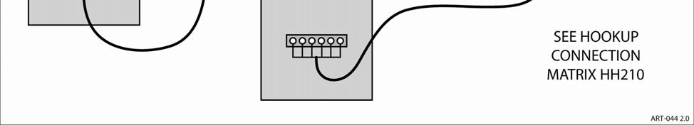
32 HP MANUFACTURERS MULTI-WIRE STAT WF-HP2 MULTI-WIRE ROOMSTAT LMC HEAT PUMP Furnace SEE HOOKUP CONNECTION MATRIX HH210 HH210 F1 10/23/ HH210
33 Conventional, 2H/2C Stat* Hookup Connection WF-HP2 I/F Module Carrier Bryant Rudd 4 Trane (Am. Std.) WF-HP2 Stat H/C HP 2- speed Gas 170 Stat H/C HP 698B Gas 315A 355M Stat H/C HP Gas Stat H/C Stat R R R R R W W1 W1 W1 W1 G G G G G Y1 Y1 Y1 Y1 Y1 O C Y2 Y2 Y2 Y2 Y2 W2 W2 E WF E GAS HP R R R R R Y Y1 Y1 Y1 Y1 RV O O B O Y2 Y2 Y2 Y2 Y2 C C C C B W1 W2 W2 W1 X2 SP L W GAS HP 2 stage Gas variable Furnace R R R 24V R W W/W1 W/W1 W W1 G G G G G C COM COM 24C B 1 W2 1 W2 1 W2 V 1 Y1 Y1 - Y1 - Y2 Y/Y2 Y Y2 Y O *This product has provisions for conventional 1H/1C, 4-wire stat see installation manual page 12 for comments. 10/23/ HH211B
34 WF-HP2 Conventional, 2H/2C Stat* Hookup Connection WF-HP2 I/F Module (continued) Stat H/C York York Frigidaire Lennox Gas Stat YZE Gas Stat HP Gas Stat HP? H/C? H/C FT4 - - FG6T H/C A19 HP Twin Single Stat R R R R R W W1 W1 W1 W1 G G G G G Y1 Y1 Y1 Y1 Y1 O C Y2 Y2 Y2 Y2 Y2 W2 E WF E GAS HP R R R R R Y Y Y1 Y Y1 RV O O O O Y2 Y2 Y2 Y2 Y2 C C C C C W1 W1 W1 OUT W2 W1 SP Y2 OUT Y2 OUT - - L L X/L - W GAS W N/C W & W2 N/C Furnace R R R R R W W1 W1/W W W1 G G G G G C C C C C 1 W Y1 Y1 Y1 Y(yel) Y1 Y2 Y Y2/Y Blue 11 Y2 O O O - Y2 N/C Gas G61MPV 10/23/ HH211B
35 Notes: 1 Jumper W1 and W2 on furnace or setup bit switches on furnace for 2 nd stage gas as a timed function. 2 and 3 The install manual, pages 11 and 12, suggest several possibilities for adding external switches. However, these include an automatic timeout sequence for High Cool. Also this WF-HP2 has a GAS (override) switch on the front. 4 RV logic peg jumper, move to H. York setups: - Defrost curve jumper per York suggested setup. - Hot Heat*, remains off. - FFuel*, remains off. - Switch point setting LTCO, remains on. - WarmFlo ODT should be used. - BP, set to 0. - Y2 lockout on. o Applies to cooling only. - Set furnace 2 nd stage for timeout. - W2 OUT and WF-HP2 W GAS is special opportunity to reprogram for Fuel on, set WF-HP2 to HP-GAS. Can be Thermidistat but must be setup as Conventional 2H/2C. - SW No. 1 off for HP - SW No. 2 off for single speed - Option 10, off for dual fuel - Do not select or enter any Balance Point, etc. values - Electro document HD322 has more details 11 Frigidaire/Nordyne furnace, 2-stage, Y screw only the ECM motor is actually setup for 3 speeds but as shipped and supplied, the Y1 and Y2 wires are under the same screw marked Y. Remove the blue wire and leave the yellow attached to the Y screw. The Y screw (yellow internal wire) is connected to WF-HP2 furnace TB-Y1. Butt connect to the blue wire and extend to HP2 furnace-y2. 10/23/ HH211B
36 CONTROL BOARD SETUP Four, Peg Jumpers HP-WF/HP-GAS always HP-WF for WarmFlo active. HP-GAS only relates to special condition and HP unit with Wgas output. RV Logic HP manufacturer specific, their specification sheet or know your product. C = Reversing valve control wire Hi (24V) during cooling H = Reversing valve control wire Hi (24V) during heating Roomstat Type HP Mfg., match to HP 6-8 wires Has RV (0) function within Y is compressor contactor H/C basic 4-wire, heat/cool Typical gas furnace and A/C R, W, G, Y Y is cool only 2 HEAT/1 HEAT Selection required, see manual Electro suggests 1 HEAT 2 HEAT/1 HEAT Must use 1 HEAT WARNING: After any peg jumper change, must do power off 10 seconds power on (reset). WF-HP2 SETUP SYS STAT TYPE 2HEAT/ 1HEAT RV LOGIC HH210 F2 10/23/ HH211B

37 CONVENTIONAL HEAT/COOL THERMOSTAT WF-HP2 10/23/ HH211B
Installation & Operating Instructions
 THE NEXT GENERATION OF THE INDUSTRY STANDARD PLENUM HEATER Installation & Operating Instructions EM-WU(WD)***D*-SL2 Series Two stage HP Equipment See specification page for model number breakdown and details
Installation & Operating Instructions
 THE NEXT GENERATION OF THE INDUSTRY STANDARD PLENUM HEATER Installation & Operating Instructions EM-WU(WD)***S*-SL1 Series One Stage HP or One or Two Stage AC See specification page for model number breakdown
ECM Blower, All Hookups, WarmFlo ST/OT CFM Selection
 Assumptions Electro-HELPS VIII ECM Blower, All Hookups, WarmFlo ST/OT CFM Selection 1. Typically the furnace will be setup for a top (Y2) speed relating to cooling requirement. Installer must determine
WARMFLO COMPATIBLE. Upflow. Number of Stages. This is a single package unit, it contains the WarmFlo II controller with a built-in WF- EZ3.
 WARMFLO COMPATIBLE Upflow EM-WU **+H* Width 5 = 15 8 = 18 Number of Stages kw Size 05 = 5 kw 10 = 10 kw This is a single package unit, it contains the WarmFlo II controller with a built-in WF- EZ3. Requires
WF-DFSLT Dual Fuel Kit
 WF-DFSLT Dual Fuel Kit Trane/American Standard ComfortLink System and/or Roomstat 900 Controller Installation & Operating Instructions Reference WarmFlo Select plenum heater product EM-WU(WD)***D*-SLT
Installation & Operating Instructions
 THE NEXT GENERATION OF THE INDUSTRY STANDARD PLENUM HEATER Installation & Operating Instructions EM-WU(WD)***D*-SLT Series Communicating Thermostat Systems, specifically Trane ComfortLink and American
ELECTRIC MAKE-UP AIR
 ELECTRIC MAKE-UP AIR WITH WARMFLO CONTROLLER EM-WM**3** 15 = 15 kw 20 = 20 kw 11 = 10 kw, 3-phase 5 = Single phase, 5 kw per stage 4 = 3-phase, 3-stage 6 = 3-phase, 3-stage H = 8w x 10d L = 8w x 16d Specific
A complete product line to fi t all your application needs GENERAL PRODUCT FEATURES
 Electro-HELPS I PLENUM HEATERS A complete product line to fi t all your application needs The Electro-Mate has been heating America s homes and businesses since 1979. We take pride in our craftsmanship
Providing Comfort Through Efficient Energy Solutions PRICE BOOK (USD) - LIST EFFECTIVE JUNE 1,
 - LIST EFFECTIVE JUNE 1,") Providing Comfort Through Efficient Energy Solutions PRICE BOOK (USD) - LIST EFFECTIVE JUNE 1, 2018 2018 www.electromn.com sales@electromn.com PLENUM HEATER WARMFLO SELECT SERIES Our all-in-one plenum
Providing Comfort Through Efficient Energy Solutions PRICE BOOK (USD) - LIST EFFECTIVE JUNE 1, 2018 2018 www.electromn.com sales@electromn.com PLENUM HEATER WARMFLO SELECT SERIES Our all-in-one plenum
Industrial Series. Electric Hot Water Boiler EB-NB Series Installation & Operating Manual
 Industrial Series Electric Hot Water Boiler EB-NB Series Installation & Operating Manual See page 1 Specification Chart for specific model by voltage and kw size. Evaluate utility service/utility transformer
Installation Instructions
 FAVXXR6C2100-A01 Vent Damper and Control Installation Instructions FAMILIARIZE YOURSELF WITH THE INSTALLATION INSTRUCTIONS BEFORE STARTING ATTENTION INSTALLER: This product must be installed by a qualified
Industrial Series. Electric Hot Water Boiler EB-NB Series Installation & Operating Manual
 Industrial Series Electric Hot Water Boiler EB-NB Series Installation & Operating Manual See page 1 Specification Chart for specific model by voltage and kw size. Evaluate utility service/utility transformer
Multiple Boilers Electro TS Series Application EB-C-STG5
 Multiple Boilers Electro TS Series Application EB-C-STG5 Drawings: BC025 BX404 BH504 XX017 Information All Electro-Boilers, except Mini-Boiler, have the same control board (EB5623**). The plug-in control
BASIC INSTALLATION AND OPERATION MANUAL
 BASIC INSTALLATION AND OPERATION MANUAL EMDI ** *5 * Size H = 8W x 10D L = 8W x 16D kw Stages 10 = 9.6 kw 2 = 2 15 = 14.4 kw 3 = 3 20 = 19.2 kw NOTE: This Duct Heater may have various installation applications.
Model 8120 and 8126 Safety & Installation Instructions
 Ventilation Controller Model 8120 and 8126 Safety & Installation Instructions FAMILIARIZE YOURSELF WITH THE INSTALLATION INSTRUCTIONS BEFORE STARTING DANGER ATTENTION INSTALLER: To prevent serious injury
Commercial Touchscreen Thermostat
 55,13M 1/27 Supersedes 12/25 Commercial Touchscreen Thermostat 25 Lennox Industries, Inc. Dallas, Texas, USA APPLICATION Page 1 INSTALLATION INSTRUCTIONS The Lennox Commercial Touchscreen Thermostat provides
ELECTRO-BOILER. Midsize INSTALLATION & OPERATING INSTRUCTIONS
 ELECTRO-BOILER Midsize INSTALLATION & OPERATING INSTRUCTIONS Model EB-MO-10 EB-MO-15 EB-MO-20 APPLICATION: This Electro-Boiler is factory equipped with WarmFlo smart controller. WarmFlo automatically regulates
Heat Pump Defrost Board Replacement Kit
 Bard Manufacturing Company, Inc. Bryan, Ohio 43506 8620-223 Heat Pump Defrost Board Replacement Kit KIT FEATURES This kit is made up of the current defrost control board 8201-129 and a new defrost sensor.
DIGI3U. Zoning Systems. Installation Guide. That s all we do. Three-Zone, Universal Controller for Gas/Electric or Heat Pump Applications
 Installation Guide DIGIU Three-Zone, Universal Controller for Gas/Electric or Heat Pump Applications -Zone Controller for the RNC Market Part #DMAN October 004 Zoning Systems That s all we do. INTRODUCTION
ELECTRO-BOILER Commercial Series
 ELECTRO-BOILER Commercial Series INSTALLATION & OPERATING INSTRUCTIONS Model EB-CX Series APPLICATION: This Electro-Boiler is factory equipped with WarmFlo smart controller. WarmFlo automatically regulates
Installation & Operation Instructions
 Installation & Operation Instructions 200 MPS Series Arzel Zoning Technology, Inc. 4801 Commerce Pkwy. Cleveland, OH 44128 Ph: (216) 831-6068 or Toll-Free (800) 611-8312 Fax: (216) 831-6074 www.arzelzoning.com
ELECTRO-BOILER. Commercial Series. INSTALLATION & OPERATING INSTRUCTIONS Model EB-C* Series
 ELECTRO-BOILER Commercial Series INSTALLATION & OPERATING INSTRUCTIONS Model EB-C* Series LOCATE EXACT NUMBER ON NAMEPLATE, LOCATE LINE ITEM ON PAGE 1 APPLICATION: This Electro-Boiler is factory equipped
Safety, Installation, and Operation Manual
 Automatic Steam Humidifier Control Safety, Installation, and Operation Manual READ COMPLETE INSTALLATION INSTRUCTIONS BEFORE STARTING. WARNING This product must be installed by a qualified heating and
Installation & Operation Instructions
 Installation & Operation Instructions Installation Precautions This Zoning System must be installed by a qualified HVAC Contractor! Caution - Electrical Hazard Can cause personal injury or equipment damage.
H32 Uni- Zone Model H32
 H32 Uni- Zone Model H32 Installation and Operating Instructions Controlling Your Comfort Room By Room F o l l o w u s o n H32 PANEL FEATURES System Mode Indicator LED Power Indicator LED HVAC Equipment
Hoffman Controls 759-ECM. Installation & Operating Instructions. Introduction. Installation. Pre-Installation Information/ Instruction
 Hoffman Controls Installation & Operating Instructions Introduction CAUTION Failure to read and understand the accompanying instructions and diagrams prior to energizing the Controller may result in permanent
OPERATION INSTRUCTIONS DEMAND DEFROST CONTROL BOARD MODEL FOR USE WITH MODELS: AFFINITY, ECHELON, ACCLIMATE HEAT PUMP SERIES
 OPERATION INSTRUCTIONS DEMAND DEFROST CONTROL BOARD MODEL 500644 FOR USE WITH MODELS: AFFINITY, ECHELON, ACCLIMATE HEAT PUMP SERIES A047-001 FIGURE 1: Demand Defrost Control Module ANTI-SHORT CYCLE DELAY
RC-112 Two Speed Heat Pump 3 Stage Heat / 2 Stage Cool With Energy Efficient Control
 O M N I S T A T ELECTRONIC COMMUNICATING THERMOSTAT Installation Manual RC-112 Two Speed Heat Pump 3 Stage Heat / 2 Stage Cool With Energy Efficient Control Document Number 13I00-5 November, 1997 CONTENTS
Installation instructions for Plenum-mounted add-on electric heaters MODEL TU. MARCH 2011 version 7
 Installation instructions for Plenum-mounted add-on electric heaters MODEL TU MARCH 2011 version 7 THERMOLEC PLENUM HEATER MODEL TU BEFORE YOU START -GENERAL SAFETY AND INSTALLATION PRECAUTIONS Please
Installation Instructions
 50ZPB, C, 50ZHB, C, PA3Z ---A, PH3Z ---A, PA4Z, PH4Z, PAJ4,PHJ4,WJA4,WJH4 SMALL PACKAGED PRODUCTS (SPP) Accessory Electric Heaters 5---20 kw For 14 SEER, R---410A Manufactured Home Installation Instructions
SC Installation, Operation & Application Guide
 SC 5211 2-Stage Heat Pump Auto Changeover Hardwire Programmable Electronic Thermostat 7-Day, 5-2-Day or 5-1-1-Day Programmable Configurable 2-Stage Heat Pump Systems Large Display With Backlight Selectable
INSTALLATION & OPERATING INSTRUCTIONS
 ELECTRO-BOILER TS Series INSTALLATION & OPERATING INSTRUCTIONS Model EB-S-13 EB-S-18 EB-S-23 EB-S-27 APPLICATION: This Electro-Boiler series is factory equipped with outlet temperature sensing and a smart
SERVICING S-15 CHECKING CAPACITOR
 S-15 CHECKING CAPACITOR The direct drive motors are of the permanent split capacitor design. A run capacitor is wired across the auxiliary and a portion of the main windings. The capacitors primary function
Operator: Save these instructions for future use!
 WHITE-RODGERS 1F83-51 Non-Programmable Electronic Digital Multi-Stage Thermostat INSTALLATION AND OPERATION INSTRUCTIONS Operator: Save these instructions for future use! FAILURE TO READ AND FOLLOW ALL
USER MANUAL WARNING! CONTENTS MODEL SPECIFICATIONS READ ALL INSTRUCTIONS BEFORE PROCEEDING
 MODEL Premier Series 3000 USER MANUAL Non-Programmable Single Stage Heat/Cool Digital Thermostat Compatible with low voltage single stage gas, oil or electric heating or cooling systems, including single
Model 1750A/ 1770A Dehumidifier Installation Instructions
 Model 1750A/ 1770A Dehumidifier Installation Instructions Safety Instructions WARNING 1. Improper installation may cause property damage or injury. Installation, service, and maintenance must be performed
Installation Instructions
 Electric Heaters 5 --- 20 kw SMALL PACKAGED PRODUCTS (SPP) Accessory Electric Heaters For 13 SEER, R---410A Manufactured Home Installation Instructions NOTE: The Dual Point Kit can only be installed on
50M56U-843 INSTALLER MUST READ DESCRIPTION PRECAUTIONS WARNING CAUTION
 50M56U-843 Universal Single Stage HSI Integrated Furnace Control Kit INSTALLATION INSTRUCTIONS INSTALLER MUST READ PAGE 3 CONTAINS WIRING HARNESS AND BLOWER CONNECTION INSTRUCTIONS FOR ALL APPLICATIONS
WARNING Important Safety Information
 1 Specifications Premier Series Non-Programmable Thermostats MODEL 3000 MODEL 3200 1 2 3 4 5 Specifications Installation Testing Your New Thermostat Programming User Settings Temperature Adjustment WARNING
LZP-2 ZONE CONTROL PANEL
 2004 Lennox Industries Inc. Dallas, Texas, USA ZONING SYSTEM 504,926M 5/2004 Litho U.S.A. LZP-2 ZONE CONTROL PANEL INSTALLATION INSTRUCTIONS FOR ZONE CONTROL PANELS USED WITH LENNOX HEATING AND COOLING
Parts Diagram. Up button. Down button. Right (fan) button. Left (system) button. RC/RH Jumper. Field programming pins
 button. Left (system) button. RC/RH Jumper. Field programming pins") Table of Contents Parts Diagram........................................................... 1 Icon Descriptions......................................................... 2 Specifications...........................................................
Table of Contents Parts Diagram........................................................... 1 Icon Descriptions......................................................... 2 Specifications...........................................................
Safety & Installation Instructions
 Premium Programmable Thermostat Safety & Installation Instructions Model 8570 READ AND SAVE THESE INSTRUCTIONS TABLE OF CONTENTS PAGE SPECIFICATIONS............................. 1 WIRE REQUIREMENTS.........................
Installation Instructions
 TP --- PRH --- A, TP --- NRH --- A PerformancetSeries Edger Thermidistatt Control Installation Instructions Programmable Control A07049 A07048 Non---Programmable Control NOTE: Read the entire instruction
Deluxe Programmable Heat Pump Thermostat T8611M
 APPLICATION Deluxe mable Heat Pump Thermostat T8611M INSTALLATION INSTRUCTIONS The T8611M Deluxe mable Heat Pump Thermostat provides electronic control of 24 Vac single-zone two compressor or two speed
Model DEHXXCDA1070 & DEHXXCDA1095 Dehumidifier Installation Instructions
 Model DEHXXCDA1070 & DEHXXCDA1095 Dehumidifier Installation Instructions Safety CONSIDERATIONS Improper installation, adjustment, alteration, service, maintenance, or use can cause explosion, fire, electrical
WARNING Important Safety Information
 1 Specifications 1 2 3 4 5 Builder Series Programmable Thermostats 2000 2000NC 2200 2200NC Single Stage Heat / Cool Conventional and Heat Pump Multi-Stage 2 Heat / 1 Cool Conventional and Heat Pump Before
Installer Guide. WARNING Important Safety Information. 1 Specifications
 1 Specifications cont. Premier Series Universal Auto Changeover Up to 3 Heat / 2 Cool Heat Pump or 2 Heat / 2 Cool Conventional Thermostat Installer Guide Before Installing, Programming or Operating, PLEASE
T7200D,E Series 2000 Commercial Microelectronic Thermostats
 T7200D,E Series 2000 Commercial Microelectronic Thermostats INSTALLATION INSTRUCTIONS APPLICATION The T7200D,E Thermostats provide electronic control of 24 Vac commercial single-zone heating, ventilating
installation and start-up instructions THERMIDISTAT CONTROL
 installation and start-up instructions THERMIDISTAT CONTROL TSTAT Cancels: II TSTAT-0-22 II TSTAT-0-27 8-99 NOTE: Read the entire instruction manual before starting the installation. This symbol indicates
RC-101 Heat Pump Real Time Pricing System 2 Stage Heat / 1 Stage Cool
 O M N I S T A T ELECTRONIC COMMUNICATING THERMOSTAT Installation Manual RC-101 Heat Pump Real Time Pricing System 2 Stage Heat / 1 Stage Cool Document Number 13I00-4 January, 1997 Copyright 1997 Home Automation,
SERVICE MANUAL FOR 6537 & 6538 SERIES TWO TON HIGH EFFICIENCY PACKAGED HEAT PUMPS
 SERVICE MANUAL FOR 6537 & 6538 SERIES TWO TON HIGH EFFICIENCY PACKAGED HEAT PUMPS TABLE OF CONTENTS 1. Warnings.................................................................. 2 2. Accessibility Of Appliance....................................................
1F60-22 INSTALLATION & OPERATING MANUAL SETBACK THERMOSTAT. Homeowner: Save this booklet for future use!
 INSTALLATION & OPERATING MANUAL SETBACK THERMOSTAT 1F60-22 PHOTO --POSITION ONLY! (For use on 24 Volt AC Heat/Cool and Heat-Only Systems) Homeowner: Save this booklet for future use! Congratulations! You
Installer Guide. WARNING Important Safety Information. 1 Specifications
 1 Specifications cont. Premier Series Universal Auto Changeover Up to 3 Heat / 2 Cool Conventional and Heat Pump Thermostat Installer Guide Before Installing, Programming or Operating, PLEASE READ ALL
OWNERS MANUAL YEAR LIMITED WARRANTY READ ALL INSTRUCTIONS BEFORE PROCEEDING. Store this booklet for future reference
 3100 Premier Series Non-Programmable 2 Heat / 2Cool & Heat / Cool Digital Thermostat OWNERS MANUAL Compatible with low voltage multi-stage heat / cool systems with up to two stages of heating and two stages
INSTALLATION MANUAL. G&F Manufacturing 7902 Interstate Court North Fort Myers, Florida
 INSTALLATION MANUAL G&F Manufacturing 7902 Interstate Court North Fort Myers, Florida Heat Pump Services 990 NW 53rd Street Fort Lauderdale, Florida 33309 G&F Manufacturing 7902 Interstate Court North
Digi-Zone Model MDP3 Ver.04
 Digi-Zone Model MDP3 Ver.04 Installation and Operating Instructions Controlling Your Comfort Room By Room System Indicator LEDs MDP3 Panel Features Power Indicator LED Leaving & Outdoor Air Sensors Zone
T8611M Deluxe Programmable Heat Pump Thermostats
 T8611M Deluxe mable Heat Pump Thermostats INSTALLATION INSTRUCTIONS APPLICATION The T8611M Deluxe mable Heat Pump Thermostat provides electronic control of 24 Vac single-zone two compressor or two speed
WARNING Important Safety Information
 1 Specifications Premier Series Non-Programmable Thermostats MODEL 3000 MODEL 3200 1 2 3 4 Specifications Installation Testing Your New Thermostat Programming User Settings WARNING Important Safety Information
T8624D Chronotherm IV Deluxe Programmable Multistage Thermostats
 T8624D Chronotherm IV Deluxe mable Multistage Thermostats INSTALLATION INSTRUCTIONS APPLICATION The T8624D Chronotherm IV Deluxe mable Multistage Thermostats provides electronic control of 24 Vac single-zone
Model 8191 & 8192 Ventilator with Dehumidification Installation and Operating Instructions
 Model 8191 & 8192 Ventilator with Dehumidification Installation and Operating Instructions ON/OFF button used to turn the ventilator on and off Up/Down buttons used to change humidity or vent time setting
Model 8191 & 8192 Ventilator with Dehumidification Installation and Operating Instructions
 Model 8191 & 8192 Ventilator with Dehumidification Installation and Operating Instructions ON/OFF button used to turn the ventilator on and off Up/Down buttons used to change humidity or vent time setting
USER MANUAL WARNING! CONTENTS MODEL 1 SPECIFICATIONS READ ALL INSTRUCTIONS BEFORE PROCEEDING 2 INSTALLATION. Premier Series
 Premier Series MODEL 5000 USER MANUAL 5-2 Day Programmable Single Stage Heat/Cool Digital Thermostat Compatible with low voltage single stage gas, oil or electric heating or cooling systems, including
EL-TSTAT-8820 Safety & Installation Instructions
 EL-TSTAT-8820 Safety & Installation Instructions TABLE OF CONTENTS WI-FI SETUP Wi-Fi Setup 2 INSTALLATION Installation location recommendations 3 Outdoor temperature sensor (included) 3 Remote temperature
INSTALLATION INSTRUCTIONS
 INSTALLATION INSTRUCTIONS Electric Heat Sections Used with Blower Coil Units ELECTRIC HEAT SECTIONS 505,084M (0655012-30) 05/15 Supersedes 09/11 Litho U.S.A. NOTICE TO INSTALLER IT IS HIGHLY RECOMMENDED
TZ-4 TotalZone Zone Control Panel
 TZ-4 TotalZone Zone Control Panel FEATURES PRODUCT DATA APPLICATION The TZ-4 TotalZone Zone Control Panel controls single-stage, multi-stage, conventional or heat pump heat/cool equipment. It controls,
tcu.z Commercial Programmable Thermostat Installation Instructions
 Application Mercury Notice Installation The tcu.z Commercial Programmable Thermostat controls 24-VAC commercial single-zone heating, ventilating, and air conditioning (HVAC) equipment. It consists of a
For Quick Set-Up go to Page 14
 Talking Thermostat Model VT3000 Guide SmartWay Solutions, Inc. US Patent 6,608,560 & 7,62,253 For Quick Set-Up go to Page 4 Model VT3000, a universal thermostat for use on most Gas or Electric, Conventional
OWNERS MANUAL YEAR LIMITED WARRANTY READ ALL INSTRUCTIONS BEFORE PROCEEDING. Store this booklet for future reference
 5100 Premier Series 7-Day Programmable 2-Heat / 2-Cool Heat /Cool Digital Thermostat OWNERS MANUAL Compatible with low voltage multi-stage heat / cool systems with up to two stages of heating and two stages
Digi-Zone. Installation and Operating Instructions. Model MDP3. Controlling Your Comfort Room By Room
 Digi-Zone Model MDP3 Installation and Operating Instructions Controlling Your Comfort Room By Room System Indicator LEDs MDP3 Panel Features Power Indicator LED Leaving & Outdoor Air Sensors Zone Terminals
T8611G Chronotherm Deluxe Zoning Heat Pump Thermostat
 T8611G Chronotherm Deluxe Zoning Heat Pump Thermostat INSTALLATION INSTRUCTIONS APPLICATION The T8611G Chronotherm Deluxe Zoning Heat Pump Thermostat provides electronic control of 24 Vac zoned heat pump
Deluxe Programmable Thermostats
 Deluxe mable Thermostats T8602D INSTALLATION INSTRUCTIONS APPLICATION The T8602D IV Deluxe mable Thermostat provides electronic control of 24 Vac single-stage heating and cooling systems or 750 mv heating
T8600D Chronotherm IV Deluxe Programmable Thermostats
 T8600D Chronotherm IV Deluxe mable Thermostats APPLICATION INSTALLATION INSTRUCTIONS The T8600 Chronotherm IV Deluxe mable Thermostat provides electronic control of 24 Vac singlestage heating and cooling
L SERIES UNITS 504,520M. 10/2001 Supersedes 504,413M
 Litho U.S.A. 2 L SERIES UNITS 54,52M /2 Supersedes 54,4M M 6 VERSION 4. INTEGRATED MODULAR CONTROL (IMC) GUIDE TO THE M 6 VERSION 4. INTEGRATED MODULAR CONTROL USED IN L SERIES THROUGH TON UNITS TABLE
Operator: Save these instructions for future use!
 WHITE-RODGERS 1F81-51 Programmable Electronic Digital Multi-stage Thermostat INSTALLATION AND OPERATION INSTRUCTIONS Operator: Save these instructions for future use! FAILURE TO READ AND FOLLOW ALL INSTRUCTIONS
Installation Instructions
 T6-PRH01-B, T6-NRH01-B Preferredt Series Thermidistat Installation Instructions A07045 Programmable Control A07044 Non-Programmable Control Designed and Assembled in the USA. NOTE: Read the entire instruction
B SERIES ELECTRIC FURNACE
 MISSISSAUGA, ONTARIO L5T 1H9 TEL.: 905-670-2500 FAX: 905-795-8311 CUSTOMER SERVICE TEL.: 1-888-882-7626 B SERIES ELECTRIC FURNACE! WARNING 1. The user MUST contact a specialized contractor when a failure
SmartZone TM System Manual
 SmartZone TM System Manual Rev C3 June 1, 2007 Page 0 of 21 Table of Contents SmartZone TM System Manual Rev C3. April 23, 2007 Introduction..2 o Why Use Residential Zoning?..2 Architectural Challenges...
INSTALLATION INSTRUCTIONS FOR 9330F4552 FREE DELIVERY PLENUM KITS
 RV Products Division INSTALLATION INSTRUCTIONS FOR 9330F4552 FREE DELIVERY PLENUM KITS 8330-752 CONTROL BOX KIT (12 VDC COOL ONLY) 9330C755 CONTROL BOX KIT (12 VDC HEAT READY) 8530-750 CONTROL BOX KIT
RCS Residential Control Systems Inc.
 RCS Residential Control Systems Inc. Model TZ16 Z-Wave Communicating Thermostat with Rev P HVAC Control Unit INSTALLATION AND OPERATION MANUAL DCN: 141-00882 Rev 02 5/18/06 This manual applies to the following
T8190A/191108AJ Heating or Cooling Thermostat/Wallplate; T8190A/Q682B Heating/Cooling Thermostat/Subbase
 M3375 M3375 T890A/908AJ Heating or Cooling Thermostat/Wallplate; T890A/Q68B Heating/Cooling Thermostat/Subbase Installation Instructions for the Trained Service Technician. Preparation NOTE: Order Q68B
G60UH(X) WARNING. WARNING Sharp edges. Be careful when servicing unit to avoid sharp edges which may result in personal injury. Service Literature
 WARNING. WARNING Sharp edges. Be careful when servicing unit to avoid sharp edges which may result in personal injury. Service Literature") Service Literature Corp. 0204 L2 Revised 11 2006 G60UH(X) G60UH(X) SERIES UNITS G60UH(X) series units are mid efficiency gas furnaces used for upflow or horizontal applications only, manufactured with
Service Literature Corp. 0204 L2 Revised 11 2006 G60UH(X) G60UH(X) SERIES UNITS G60UH(X) series units are mid efficiency gas furnaces used for upflow or horizontal applications only, manufactured with
Installation instructions for Plenum-mounted add-on electric heaters MODEL TU. September 2016 Version 7
 Installation instructions for Plenum-mounted add-on electric heaters MODEL TU September 2016 Version 7 THERMOLEC PLENUM HEATER MODEL TU BEFORE YOU START -GENERAL SAFETY AND INSTALLATION PRECAUTIONS Please
Digital Programmable
 www.geappliances.com Digital Programmable Thermostats Operating Instructions Auto Changeover..........10 Day/Time Setting Mode.....6 Default Mode...............4 Fan Control...............10 Hold and Temporary
SC Installation, Operation & Application Guide
 SC 5811 2 Heat/2 Cool Auto Changeover Hardwire Programmable Electronic Thermostat 7-Day, 5-2-Day or 5-1-1-Day Programmable Configurable 2-Stage Heat/2-Stage Cool Systems 2-Stage Heat Pump Systems Large
OWNERS MANUAL YEAR LIMITED WARRANTY READ ALL INSTRUCTIONS BEFORE PROCEEDING. Store this booklet for future reference
 3000 Premier Series Non-Programmable Single Stage /Cool Digital Thermostat OWNERS MANUAL Compatible with low voltage single stage gas, oil or electric heating or cooling systems, including single stage
Electro-HELPS XV ELECTRO-BOILER SPECIFICATIONS. A complete product line to fi t all your application needs. Made in USA
 Electro-HELPS XV Made in USA ELECTRO-BOILER SPECIFICATIONS A complete product line to fi t all your application needs The Electro-Boiler has been heating America s homes and businesses since 980. We take
Installation Instructions
 P700U -21NHP Base Non -Programmable Thermostats Installation Instructions Designed and Assembled in the USA. US patents: US20060165149 A1, USD578026 SI, US6205041 B1 A14005 Base Non---Programmable Thermostat
Installation Instructions
 T2 -PAC01 -A, T2 -NAC01 -A T2 -PHP01 -A, T2 -NHP01 -A LEGACYt SERIES THERMOSTATS Installation Instructions A07047 Legacy Series Programmable Thermostat A07046 Legacy Series Non-Programmable Thermostat
Safety & Installation Instructions
 Model 6303 & 6302 Zoned Comfort Control Safety & Installation Instructions READ AND SAVE THESE INSTRUCTIONS 61001212A 6302-6303 Zoned Comfort Control Install.indd 1 TABLE OF CONTENTS SAFETY INSTRUCTIONS..........................................
Electro Industries Make-Up Air II
 --------------------------------------------------------------------------------------- Installation & Operating Manual ---------------------------------------------------------------------------------------
Leading Word on Lag Modules
 Electronic Service Inc. KW Electronic Service Inc. and Viessmann, partners in heating technology. Controls newsletter, May 2002, Issue 2 T hank you to everyone who responded to our first edition of VITOTALK.
Emerson Inspire 1HDEZ Installation Instructions. Thermostat/Interface Equipment Control TROUBLESHOOTING
 Emerson Inspire 1HDEZ-1521 Installation Instructions Thermostat/Interface Equipment Control TROUBLESHOOTING FAILURE TO READ AND FOLLOW ALL INSTRUCTIONS CAREFULLY BEFORE INSTALLING OR OPERATING THIS CONTROL
MODEL AC-SCC-5 INSTALLATION, OPERATION & MAINTENANCE MANUAL
 5CIM2-0413 W30-AC0056 MODEL AC-SCC-5 INSTALLATION, OPERATION & MAINTENANCE MANUAL Multi-zone Hydronic Chiller Interface Module SECTION 1: INTRODUCTION Unit description... 5 Location... 5 Handling... 5
50M56U-843 Universal Single Stage HSI Integrated Furnace Control Kit INSTALLATION INSTRUCTIONS
 50M56U-843 Universal Single Stage HSI Integrated Furnace Control Kit INSTALLATION INSTRUCTIONS INSTALLER MUST READ PAGE 3 CONTAINS WIRING HARNESS AND BLOWER CONNECTION INSTRUCTIONS FOR ALL APPLICATIONS
INSTALLATION INSTRUCTION
 INSTALLATION INSTRUCTION MODULAR AIR HANDLER MODEL: N*AH CONTENTS GENERAL... 1 INSPECTION... 2 REFERENCE... 2 LIMITATIONS... 2 LOCATION... 2 BLOWER/COIL ASSEMBLY UPFLOW AND HORIZONTAL INSTALLATIONS...
OPERATING INSTRUCTIONS
 COMFORT CONTROL CENTER 2 THERMOSTAT OPERATING INSTRUCTIONS PROGRAMMABLE THERMOSTAT MODEL 3314080.000 BLACK 3314080.015 WHITE USA SERVICE OFFICE Dometic Corporation 1120 North Main Street Elkhart, IN 46514
Installation Instructions
 Installation Instructions DIGITAL THERMOSTAT 53DFS250-SL Cooling Only, Heat Cool, and Heat Pump B. Assemble tools: o AUTO COOL HEAT o MULTI-STAGE SEVEN DAY PROGRAMMABLE Table of Contents STEP #1 PREPARATION
RC-90 / RC-90B Single Stage Heat/Cool Thermostat for Zone Control Systems Installation Instructions
 RC-90 / RC-90B Single Stage Heat/Cool Thermostat for Zone Control Systems Installation Instructions DESCRIPTION The RC-90 is a precision digital thermostat designed for 24 VAC single stage heating and
USERS INFORMATION MANUAL
 MODULAR DX OR CHILLED WATER COOLING WITH ELECTRIC OR HOT WATER HEATING MODELS: US, UM SERIES USERS INFORMATION MANUAL For Installation In: 1. Modular Homes & Buildings 2. Residential Homes LIST OF SECTIONS
T8602C Chronotherm IV Deluxe Programmable Thermostats
 T8602C Chronotherm IV Deluxe mable Thermostats INSTALLATION INSTRUCTIONS APPLICATION The T8602 Chronotherm IV Deluxe mable Thermostat provides electronic control of 24 Vac single-stage heating and cooling