Keep this booklet for service log and future reference IMPORTANT
|
|
|
- Augusta Maxwell
- 5 years ago
- Views:
Transcription

1 Instruction for user, Installation & Servicing 480HD Keep this booklet for service log and future reference IMPORTANT This appliance is guaranteed for 12 months subject to conditions. The 5 year extended parts warranty will only be valid if the annual service recommended in this manual has been completed and appliance has been registered online.

2 Contents Benchmark Scheme... 2 Introduction... 3 Consumer Protection Information... 3 Important Information... 4 Lighting The Appliance & General Operation Of Controls... 5 Auto (Thermostatic) Control... 7 Menu features... 8 Changing The Handset Batteries Cleaning The 480 HD Appliance Fuel Bed Layout Silver Birch Fuel bed Walnut fuel bed Technical Specification Siting the Appliance Installation of the Appliance Commissioning The Appliance Annual Service Requirement Fault Finding Charts Maintenance Short Spares List Your Fire Years Parts Extended Warranty Four Year Service Log Details GAS FIRE COMMISSIONING CHECKLIST Register Your 12 Month Warranty with Us Today EXTENDED FIVE YEAR PARTS WARRANTY In order to validate your extended 5 years parts warranty please read the Benchmark Scheme and ensure your installer has filled in the appropriate checklist. P a g e 1


3 480 HD USERS INSTRUCTIONS Benchmark Scheme Charlton and Jenrick Ltd is a licensed member of the Benchmark Scheme which aims to improve the standards of installation and commissioning of domestic heating and hot water systems in the UK and to encourage regular servicing to optimise safety, efficiency and performance. Benchmark is managed and promoted by the Heating and Hotwater Industry Council. For more information and the full code of practice please visit Please ensure that the installer has fully completed the Benchmark Checklist on the inside back pages of the installation instructions supplied with the product and that you have signed it to say that you have received a full and clear explanation of its operation. The installer is legally required to complete a commissioning checklist as a means of complying with the appropriate Building Regulations (England and Wales). All installations must be notified to Local Area Building Control either directly or through a Competent Persons Scheme. A Building Regulations Compliance Certificate will then be issued to the customer who should, on receipt, write the Notification Number on the Benchmark Checklist. This product should be serviced regularly to optimize its safety, efficiency and performance. The service engineer should complete the relevant Service Record on the Benchmark Checklist after each service. The Benchmark Checklist will be required in the event of any warranty. It is a requirement that the gas fire is installed and commissioned to the manufacturer s instructions and the data fields on the commissioning checklist completed in full. To instigate the guarantee, the gas fire needs to be registered with the manufacturer within one month of the installation. To maintain the guarantee, it is essential that the gas fire is serviced annually by a Gas Safe registered engineer. The service details should be recorded on the Benchmark Service Interval Record and left with the householder. P a g e 2
4 480 HD USERS INSTRUCTIONS Introduction The 480 HD has been designed and tested to the requirements of EN 613 and is suitable for use in Great Britain & Republic of Ireland. 480 HD incorporates a single gas valve which selects ignition pilot, with variable setting between low and high setting and is operated via remote control hand device or optional smart app device. This system is powered by mains electricity via pre-wired transformer plus supply cord. Alternative supply by batteries is available for use during mains interruption. The 480 HD incorporates a safety device in form of an Oxygen Depletion System, which constantly monitors the oxygen in the room and will cause the fire to switch off if the oxygen level reduces, for instance due to insufficient ventilation or a blocked flue. Consumer Protection Information As manufacturers and suppliers of heating products, we take every care to ensure that the design and construction has to meet the general safety requirements when properly used and installed. To this end, our products are thoroughly tested and examined before despatch. Any alteration that is not approved by the manufacturer could invalidate the approval of the appliances, operation of the warranty and could affect your statutory rights. This appliance could contain some materials that could be interpreted as being injurious to health. It is the users / installers responsibility to wear protective clothing when handling the following materials. Artificial fuel, mineral wool, insulation material, refractory/ceramic fibres and glass yarn. May be harmful if inhaled, may be irritating to skin, eye, nose and throat. When disposing refractory / ceramic materials to keep dust to a minimum these materials should be securely wrapped in polythene and clearly labelled RCF waste. These materials are not classified as hazardous waste and should be disposed of at a site licensed for disposal of industrial waste. P a g e 3
5 480 HD USERS INSTRUCTIONS Important Information The appliance is for use on Natural Gas 20mbar) only. The Chimney or flue (unless new or previously used with a gas appliance) should be swept before installation if it been used for solid fuel. In Great Britain, the appliance must be installed by a competent person whose name appears on the gas safe register. All Gas Safe engineers should possess an ID carrying the logo below. In IE (Ireland), the appliance must be installed by a competent person and installed in accordance with the current edition I.S 813 Domestic Installation. The glass front of this appliance acts as a dress guard, conforming to BS 1945 (1997) however a fireguard to BS6539 (1997) must be used to protect young children, the elderly or infirm. The Appliance must not be used with the glass safety screen removed or if it is damaged or cracked. During initial burn off, an odour may be evident during the first few hours of use. This is due to the surface coating on the metal work burning off. The odour produced is harmless and will disappear after a short period of time. During the normal operation of the fire some black staining may appear on some parts of the fuel bed. This is quite normal. However, if excessive black staining occurs it may be due to the fuel bed shapes laid incorrectly. This should be checked prior to contacting a service engineer. Care must be taken to prevent any damage being caused to surrounding soft furnishing or decoration. Many embossed vinyl coverings may become discoloured if placed too close to the appliance. It is suggested that a sample of the proposed wall covering should be place above the appliance at its hottest point first. The appliance should then be run on high rate over a couple of days It is advised that this appliance should be serviced annually as recommended by Gas Safe. This is more likely to provide trouble-free operation and is a requirement of the extended warranty. In GB (Great Britain) the fire does not normally require purpose built ventilation, but if for any special reason purpose built ventilation is provided it should be checked periodically to ensure freedom from obstructions. In IE (Ireland) permanent ventilation must comply with the current edition of IS813. P a g e 4
. Pressing and holding displays an UNLOCK graphic Fig 2 prompting the button to be pressed simultaneously.")
6 480 HD USERS INSTRUCTIONS Lighting The Appliance & General Operation Of Controls Display overview Press to awaken the handset from its dormant sleep mode at any time. Fig 1 shows the display neutral, ready to turn on. Turn on (start up). Pressing and holding displays an UNLOCK graphic Fig 2 prompting the button to be pressed simultaneously. Whilst both & are pressed a progress bar Fig 3 will complete. If either button is released before the progress bar has completed the operation will cancel. Once the progress bar has completed the handset will display the status of the fire (priming ignition pilot main burner) finishing at the fire on display screen Fig 4. P a g e 5

 To turn the appliance off, press and hold down until the progress bar has completed. If the is released before the progress bar has completed the operation will cancel.")

7 480 HD USERS INSTRUCTIONS Flame height adjustment Once the fire has been started the flame height can be decreased by moving your finger clock wise or decreased moving your finger anti-clock wise using the selector wheel. Once the desired flame level is set, remove your finger from the selector wheel to transmit your selection to the receiver. Six flame levels and a pilot setting are selectable. Press whilst the display is active to display the current flame level. Turn off (shut down) To turn the appliance off, press and hold down until the progress bar has completed. If the is released before the progress bar has completed the operation will cancel. Mode select With the fire running on manual operation you can access three further modes. Press for mode. Use the selection wheel to cycle through the three options, Auto, Sleep and Light. Press to select Auto or Sleep Sleep:- Use the selector wheel to choose from the available time range of 5 minutes to 1 hour 30 minutes. Once the desired countdown time has expired the appliance will turn off. By pressing the button during the countdown will cancel the countdown timer if required. Note: The handset contains a sensitive temperature measurement device. To achieve the best thermostatic efficiency do not place the handset near the heat source, avoid covering, direct sunlight or near a draft or open window etc. Place the handset at a midpoint in the room or area being heated. Allow 5-10 minutes for the handset to stabilize if subjected to extremes of temperature. P a g e 6

8 480 HD USERS INSTRUCTIONS Auto (Thermostatic) Control Press to awaken the handset from its dormant sleep mode at any time. Selecting auto control The auto function can only be selected once the appliances has been started and initiated into manual mode. Once in manual mode, press and release the button to enter the mode options. Auto is the first option, press to enter auto mode. Adjusting target temperature Use the selection wheel to increase or decrease the temperature to the desired level, release your finger from the wheel to transmit the target temperature (See Fig 5) to the receiver. The auto function will now modulate the flame height to achieve your target temperature. The selectable temperature range is 1 degree C to 29 degree C. Cancelling auto function Press to end and cancel the auto control. The handset will return to manual control. P a g e 7

9 480 HD USERS INSTRUCTIONS Menu features The menu can be accessed by pressing and holding the button (approx. 5 seconds) until the menu graphic completes (see fig 6). Use the selector wheel to highlight one of the available options. Press to enter the required option. Set clock The handset clock has a dedicated 24 hour display. Use the selector wheel to firstly set the hours. Press to change to minutes select. Use the selector wheel to change the minutes. Press the button to alternate hours and minutes to make any other alterations. Finally, press the button to save the clock setting. Display Temperature display units-use selector wheel to select either Celsius (degree C) or Fahrenheit (degree F). Press the button to save selection. Gas fire (pair code) The device screen displays the current operating channel of the handset. To delete the channel press & simultaneously or to return to the menu option. Reset To restore the handset back to its original factory setting select reset from the menu options. Press - & - simultaneously to complete the reset command to return to the menu options. Changing The Handset Batteries. The handset operates from four AAA 1.5V batteries. New alkaline batteries are recommended. Do not mix new and old batteries. When inserting the batteries, observe and position batteries according to the battery compartment graphics (see Fig 7). When the batteries are inserted this handset will attempt to repair. P a g e 8
.")


10 480 HD USERS INSTRUCTIONS Cleaning The 480 HD Appliance. Ensure the appliance is cold before proceeding. The outer metal work frame should be cleaned using a damp cloth. To clean the glass panel, remove the two fixing covers and the two M4 nuts fixing the glass clamp to the glass panel. (See Fig 8). With the nuts removed, pull the glass clamp clear of the four studs. Finally lift the glass panel out of the bottom glass fixing. Fixing cover slides over the top of the fixing bracket and hooks over the back of the bracket Using a damp cloth and warm soapy water will remove a majority of stains. For more substantial marking we recommend the use of ceramic hob cleaner. These are available from all leading super markets. The brands of hob cleaner we have tested and found suitable are Hob brite & Bar Keepers Friend. Ensure the glass is dry and re-assemble, being careful not to over tighten the glass as this will cause breakages. Note- Never operate the appliance when the glass panel is removed or broken. The glass may discolour quickly when first installed, and it should be cleaned. This is due to the burning of the refractory fuel bed shapes. P a g e 9
11 480 HD USERS INSTRUCTIONS To Clean the Pilot assembly. Remove the two M4 nuts and glass clamp (See Fig 8). Carefully lift the glass panel from within the bottom location. Remove the log and bark chip shapes. Lift out the air tray assembly from within the burner shelf. The pilot is located on the right hand side of the appliance, remove any debris in or around the pilot head and the aeration hole. This can be achieved using the nozzle of a vacuum cleaner. It is advisible not to blow the debris within the pilot head or aeration hole as this may cause more of a restriction and not rectify the problem. Note-Take care when cleaning in this area so as not to damage the pilot assembly. Cleaning the fuel bed shapes. (Please refer to customer protection information on page 3 of this booklet before cleaning or replacing any refractory materials). The fuel bed components are delicate and they should be handled with great care. They can be brushed very gently with a soft brush to remove dust or any deposits. A vacuum cleaner may only be used after the loose components and moulded shapes have been removed from the 480 HD fire box. It is important that all fuel bed shapes are positioned as shown in these instructions. P a g e 10
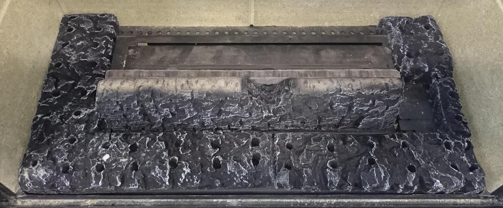
12 480 HD USERS INSTRUCTIONS Fuel Bed Layout Silver Birch Fuel bed The Log & bark shapes must be positioned in accordance to the following instructions to give the correct flame picture & reduce the risk of glass staining. Slide the log piece behind the burner Make sure not to cover the burner slots on the front burner P a g e 11
13 480 HD USERS INSTRUCTIONS Side on view 480 HD USERS INSTRUCTIONS Slide air tray in to place make sure it is central and sitting flat P a g e 12
14 480 HD USERS INSTRUCTIONS P a g e 13
15 480 HD USERS INSTRUCTIONS Split the pack of Embaglow in half Keep one half of the Embaglow for annual service P a g e 14
16 480 HD USERS INSTRUCTIONS Stretch out HALF of the Embaglow like a net Lay the stretched out Embaglow along the front burner slots avoiding going pass the cross lighting lug Avoid getting the Embaglow fibers near the pilot as it is conductive material. Failing to follow this instruction here may result in ignition and cross lighting issues P a g e 15

17 480 HD USERS INSTRUCTIONS P a g e 16


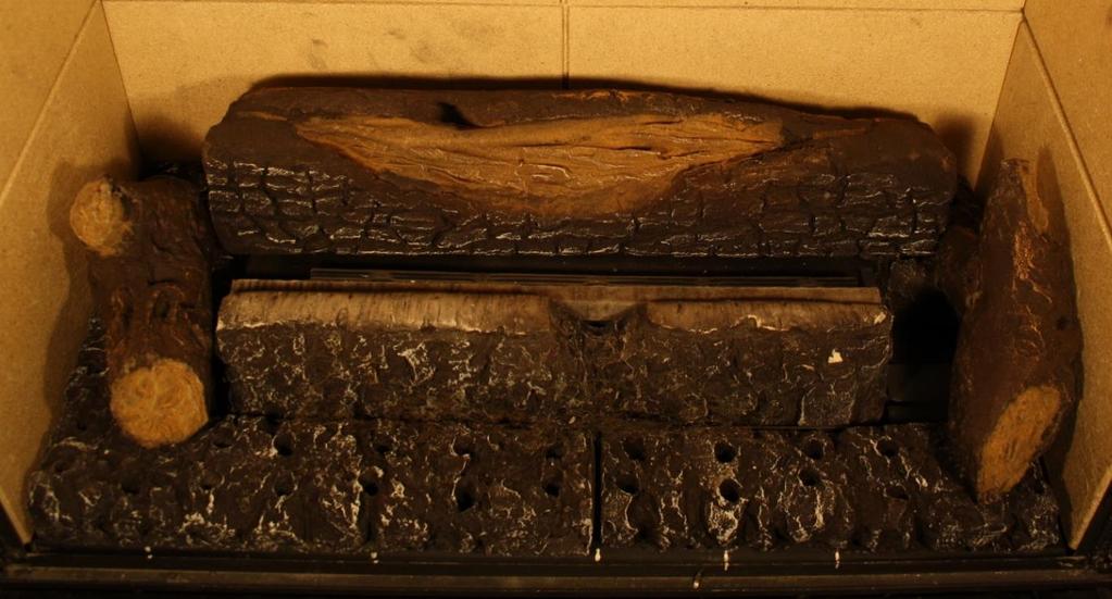
18 480 HD USERS INSTRUCTIONS This center log must be in line with the cross lighting lug on the front center log P a g e 17


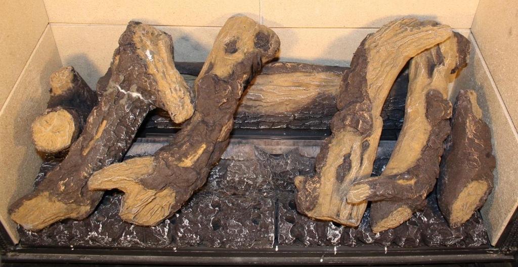
19 Walnut fuel bed 480 HD USERS INSTRUCTIONS Slide the log piece behind the burner Make sure not to cover the burner slots on the front burner P a g e 18


20 480 HD USERS INSTRUCTIONS Side on view 480 HD USERS INSTRUCTIONS Slide air tray in to place make sure it is central and sitting flat P a g e 19

21 480 HD USERS INSTRUCTIONS P a g e 20


22 480 HD USERS INSTRUCTIONS Split the pack of Embaglow in half Keep one half of the Embaglow for annual service P a g e 21


23 Stretch out HALF of the Embaglow like a net 480 HD USERS INSTRUCTIONS Lay the stretched out Embaglow along the front burner slots avoiding going pass the cross lighting lug Avoid getting the Embaglow fibers near the pilot as it is conductive material. Failing to follow this instruction here may result in ignition and cross lighting issues P a g e 22


24 480 HD USERS INSTRUCTIONS This log will look like this before putting in place This log will look like this before putting in place P a g e 23

25 480 HD USERS INSTRUCTIONS P a g e 24


26 480 HD USERS INSTRUCTIONS This center log must be in line with the cross lighting lug on the front center log P a g e 25
27 480 HD INSTALLATION INSTRUTIONS Technical Specification Model Gas Gas Working Front Rear Gas NOX Oxy Country CAT Type Pressure Injector Injector Input Class Pilot 480 HD I2H Natural Gas 20 mbar Mrk 170 Mrk KW Gross NGR GB, IE Efficiency Class 1 Gas Inlet Connection Size 8mm Handset Replacement Batteries 4 x AAA 1.5V Power Supply Type Plug Input : VAC 50/60 Hz, 0.2A Note : The efficiency of the appliance has been measured as specified in BS A1:2013 and the net efficiency rating is %. The gross calorific value of the fuel has been used for this efficiency calculation. Gastec have certified the test data from which it has been calculated. The efficiency value may be used in the UK Government s Standard Assessment Procedure (SAP) for energy rating of the dwelling. Within the appliance packaging will be an outlet restrictor, this is there to achieve the maximum efficiency. This, however may not be fitted due to the flue underperforming. P a g e 26
28 480 HD INSTALLATION INSTRUCTIONS Packaging Check List 1 x Glass Panel 1 x Air Tray Assembly 1 x Boxed Fuel Bed 1 x Transformer Plug 1 x Battery Holder 1 x Emergency Power Battery Adaptor 1 x RF Handset 4 x AAA 1.5V Batteries Siting the Appliance Regulation and warnings This appliance must only be installed in Great Britain and Eire. The appliance is suitable for use on natural gas only. When fitted in the GB the fire does not normally require purpose provided ventilation In GB it is the law that all gas appliances must be installed by a competent person GAS SAFE registered installer, in accordance with the Current Gas Safe (installation and user) Regulations. All relevant parts of the local and national building regulations and all relevant recommendations of the following British standards. Failure to do so could lead to prosecution. The following are relevant codes of practice and British Standards:- B.S 5871 B.S 5440 Part 1 & Part 2 B.S 6891 This appliance must be installed to current versions of the above standards and include any relevant amendments to:- The building regulations issued by the department of the environment. The building standards (Scotland) (Consolidated) Regulations issued by the Scottish development office. Eire the appliance must be installed by a competent person and installed in accordance with the current edition of I.S 813 document gas installation, the current building regulations and the current ETCI rules for electrical installation, if appropriate. P a g e 27
29 480 HD INSTALLATION INSTRUCTIONS Prior to installation ensure that the local distribution conditions (identification of the type of gas and pressure) and adjustment of the appliance are compatible 20 mbar. The front of the fire act as a dress guard, conforming to BS 1945 (1971) and satisfies the heating appliance regulations (1991). However, a guard conforming to BS6539 (1984) must be used to protect young children, the elderly or infirm. This appliance incorporates a safety device in form of an oxygen depletion system. It must not be adjusted or put out of operation. This is a non serviceable item and must be exchanged as a complete assembly using only the original manufacturer s part. A suitable proprietary fire surround with a 150 degree C minimum rating is required. Class One That is a conventional brick or stone chimney as used for a solid fuel appliance with an effective cross sectional dimension of 225 x 225mm or a lined flue with a minimum diameter of 125mm. The chimney must have a minimum effective height of at least 3 metres. Any permanent flue restriction or variable damper are to be removed or locked fully open. The chimney should be swept prior to installation if it has previously been used with a gas appliance or if it is a new installation. The 480 HD is designed to be fitted into a class one flue with a fire place which will require a 50mm rebate. The other option is hole in the wall which can be plastered up to the edge of the fire place frame or fitted with wall mounted noncombustible slips. The two methods will require different size apertures. Builder s opening aperture size when fitted in conjunction with a 50mm rebated surround P a g e 28

30 480 HD INSTALLATION INSTRUCTIONS Open the firebox aperture to the sizes given in the 50mm rebated surround diagram. Please note the fire box height from the floor may well vary dependent on the fireplace surround design. Check the fireplace details first. Slide the fire box back into the catchment area and secure the fire box against the front face of the chimney breast. Fit the fire place frame to the fire box flange. The fireplace surround can now be constructed. The 480 HD can be installed using three different methods when going hole in the wall. A-Hole in the wall using none combustible slips. B-Dry lined hole in the wall. C-Wet plaster hole in the wall. P a g e 29
31 480 HD INSTALLATION INSTRUCTIONS A-B-C / Builder s opening aperture size when fitting hole in the wall plaster edge or slips. A-Hole in the wall using none combustible slips. P a g e 30
32 480 HD INSTALLATION INSTRUCTIONS Using rawl plugs and wood screws retain the fire box via the 6mm holes within the slip brackets. None combustible slips can now be fitted up to the edge of the fire place frame. B-Dry lined hole in the wall. P a g e 31
33 480 HD INSTALLATION INSTRUCTIONS Open the aperture size to accommodate the fire box as out lined at the beginning of the section. With the height of the opening established and support for the fire box in place, take out a further area of the plaster board lining to expose the inner brick work face of the chimney breast as out lined in Fig 1. The exposed area should be 822 mm from the base of the fire and 744 mm in the width. With the slip bracket attached to the fireplace frame. Secure the fire box back against the inner brick work face of the chimney breast using rawl plugs and wood screws. New plaster board can now be fitted to cover the exposed metal work, making sure that no plaster joints are positioned directly above the unit as highlighted in the Fig 2 above. C-Wet plaster hole in the wall. When the chimney breast front has been finished using wet plastered method and the total thickness of the bonding plus finishing plaster is less than 12mm. The following method will need to be applied. Fit the fire box using the guidance stipulated earlier in the section when fitting the fire box with none combustible slips. With the fire box secured fit 15mm thick plaster board section to cover the complete front area of the chimney breast up to the forward projected edge of the firebox frame. Please note avoid any plaster board joints directly above the unit. P a g e 32
34 480 HD INSTALLATION INSTRUCTIONS The 480 HD is designed for installation within the masonry chimney with or without a flexible line. If the flexible liner option is required the following two methods should be followed. Method 1 A 125mm minimum diameter liner conforming to BS 715 may be used. Providing a suitable sealing plate is fitted to the base of the liner and the appliance does not restrict the opening into the liner. Ensure a smooth lead into the flue way and no combustible materials are used. A void of 50mm must be maintained from the top of the firebox into flue. Method 2 Using the flexible liner gather hood (Part No A-0662). Using again 125mm minimum diameter liner conforming to BS 715, route the flexible liner within the masonry as of the requirements stipulated by the liner manufacturer. Attach the gather hood to the liner using a suitable fixing at a height that clears the firebox assembly. Remove the inner and outer inspection plate situated within the rear of the fire box assembly (Please see Fig 1). P a g e 33
35 480 HD INSTALLATION INSTRUCTIONS Installing with a flexible liner. Offer the fire box assembly within the masonry aperture at the same time guiding the gather hood within the guides situated on the top of the fire box (Please see Fig 2). Engage the hood studs within the slotted holes and secure using the three M4 nuts provided within the gather hood kit. Checking the flue fire opening and fire opening. Check that the chimney conforms to the required specification as previously stated. Examine the condition and carry out any remedial work including removing any debris from the base. If the flue has been used for solid fuel it should be swept prior to installation. Prior to installing the appliance a smoke test (using a bomb) should be carried out to check that satisfactory smoke clearance has been established. If all the smoke is not drawn into the flue, pre-heat the flue with a blowtorch or similar and retest. If there is any uncertainty examine for the cause and if necessary seek expert advice. When installing the appliance against a dry lined plasterboard wall ensure that the void between the plaster board and wall is sealed with a non-combustible material. No combustible material should be fitted inside the fireplace opening. P a g e 34


36 480 HD INSTALLATION INSTRUCTIONS Installation of the Appliance Optional Wi-Fi Kit Installation The Kit contains the following components: 1 x Wi-Fi Dongle. 5 x self adhesive aluminum clips. 1 x Wi-Fi lead. 2 x M3 nuts and washers Remove the 2 off screws retaining the ECU cover from the LH side of the burner carrier. Lift off the cover plate to allow access to the ECU unit. Within the ECU unit will be a clear port connection labeled SENSOR. Inset the Wi-Fi connector plug within the open port. Connect the opposite end to the lead within the Wi-Fi Dongle. P a g e 35

. Retain the Wi-Fi dongle receiver using the nuts and washers provided.")
37 480 HD INSTALLATION INSTRUCTIONS With the dongle connected to the lead, locate the unit within the two M3 studs position on the left hand side of the fire box. When positioning the Wi-Fi unit it is important to have the cable socket facing the rear of the fire box. (Please note when installing the dongle with appliances using a four sided trim option. The studs with the base of the fire box unit should be used. Failure to do this could result in over heating issues). Retain the Wi-Fi dongle receiver using the nuts and washers provided. Finally using the aluminum clips provided retain the excessive lead to the base of the fire box. P a g e 36
38 480 HD INSTALLATION INSTRUCTIONS Gas supply routing. Check the gas run to assess that the gas supply is capable of providing the required amount of gas and is in accordance with the rules in force. Soft copper pipe can be used to install the appliance. Soldered joints can be used only externally of the appliance. The appliance is supplied with a factory fitted isolation device to allow for an 8mm copper connection. No further isolation point is required. The new gas line must be purged of any debris, prior to final connection to the appliance. Gas inlet isolation device is located on bottom left hand side of the fire box, the gas supply entry point is positioned at the rear bottom on left hand side. With the appliance fixing kit is a 35mm round seal (Please see fig 3), this should be cut and fitted over the 8mm copper at the point the gas supply entry into the appliance assembly. The gas inlet cover will need to be removed to gain access to the connection. (Please see fig 4). The gas inlet isolation device must be angled to allow access to the grub screw and gas test nipple. (Please see fig 3). Angle the inlet isolation device to allow access to the grub screw and test nipple 35mm round seal will need to be cut and engaged within the firebox to form an air tight seal around the inlet gas supply pipe P a g e 37
39 Power lead routing 480 HD INSTALLATION INSTRUCTIONS The power supply for this appliance is provided via AC power adaptor 230 VAC. The main cable terminates at the rear Right hand side of the fire box. The length of the cable provided with the appliance is 1.65 metres. Care must be taken when siting the fire box not to trap the exposed main cable within the builders opening. The cable can be routed using the following two methods, Method 1 Passing the cable through the side of the chimney breast. It is good practice to run the cable within a sleeve of at least 15mm internal diameter, sealing the sleeve using a suitable sealant at the point the sleeve / cable terminates the chimney masonry. Method 2 Remove a channel out of the outer skin of the Dry / wet plaster of the chimney breast up to the main power point. Again it is good practice to run the cable within a sleeve of at least 15mm internal diameter. With power points that exceed the 1.65 metre distance, an optional 2.0 metre extension cable is available Part No The cable system consists of retro fitting plug sockets which offers the following options. (Please see figure 5). P a g e 38
40 480 HD INSTALLATION INSTRUCTIONS The battery manual override option is a backup supply in case of a power failure / power cut to the property. The battery holder and adaptor lead are provide within the packing of the appliance. (Please note that the C cell batteries are not included). It is good practice to demonstrate the battery option to the customer during the commissioning process. Fire Box Installation Note: - When installing the appliance with a 3 inch (75mm) rebated surround the optional 30mm spacer frame Part No 7569 will be required. The fire box assembly can be retained using the following two methods. Secure the firebox when fitted with 50mm rebated surround Using suitable rawl plugs and wood screws retain the fire box using the four 6mm holes within the firebox flange. With the fire box secured, slide the fireplace frame assembly over the four 4mm studs projecting forward from the fire box flange. Fix the frame to the fire box using the M4 nuts and the nut spinner provided within the appliance packaging. (Please see figure 6) P a g e 39
41 480 HD INSTALLATION INSTRUCTIONS Hole in the wall. For hole in the wall installation, two additional fixing brackets will be needed that are attached to the fireplace frame LH and RH. Attach the two brackets using the 6 off fixing screws provided with the kit. Secure the complete assembly using suitable rawl plugs and wood screws via two 6mm holes within the wall fixing brackets. (Please see Figure 7). (Please Note). The fireplace frame is supplied with the slip guides attached. To improve the overall appearance of the appliance the guide brackets can be detached by removing the No 6 shelf tapping screws from within the fireplace frame assembly. P a g e 40


42 480 HD INSTALLATION INSTRUCTIONS Fixing the glass fascia Using A-B-C / Builder s opening aperture size when fitting hole in the wall plaster edge or slips instructions on page 30 to place fire on the wall. Secure fire in place to the wall with 4 suitable screws and rawl plugs (not provided) Screws here to secure fire in place P a g e 41

 Make sure")

43 480 HD INSTALLATION INSTRUCTIONS Slide fixing frame for the glass fascia over the studs and secure in place with 4 fixings nuts (provided in kit) Make sure the heat deflector is fitted at the top of the fire Use the fixing nuts here P a g e 42


44 480 HD INSTALLATION INSTRUCTIONS Perform the spillage test at this point before fitting the glass fascia. Refer to the spillage test procedure on page 47 for guidance on how to perform this test on this appliance. Now the fire is ready for the glass fascia to be hooked on using the studs on the fascia sliding them in to place on the slots provided in the side of the fixing frame. These studs are on both sides of the fascia these slide in to the slots on the slide of the fixing bracket Once fitted make sure that the heat outlet hole in the fascia is at the top to allow for heat disapation P a g e 43

45 480 HD INSTALLATION INSTRUCTIONS Commissioning The Appliance Checking gas soundness and running pressure. Turn on the supply to the appliance and check for soundness in accordance with the current codes of practice. Turn off the gas supply at the external isolation valve. Remove the pressure test point screw from the inlet elbow and connect the pressure gauge. Turn on the gas to the appliance at the isolation valve. Light the appliance as described in the user instruction section. Page 4 turn on (startup). Check the inlet pressure is 20 mbar +/- 1.0 mbar with other appliances running. Turn off gas supply, at the isolation valve. Disconnect the pressure gauge and replace the pressure test point screw. Turn on the appliance and check the pressure test point for soundness with detection fluid. Refit the gas cover as shown in Fig 4 (page 39). P a g e 44

46 480 HD INSTALLATION INSTRUCTIONS Fuel Bed Layout. Fuel bed layout should be fitted using the guidance stipulated on pages of the User Instruction section. Fit Glass Panel. Due to transit protection, the glass panel is packed with a protective sleeve within the packed appliance. Special care should be taken when removing the glass panel from the packing. The top fixing is attacked to the fire box via 2 off M4 fixing nuts. Remove the nuts and remove the top fixing bracket. (Please see fig 8 within the user instruction section). Locate the glass panel within the bottom retaining slot and push back against the seals. (Please see Fig 11). Glass panel Glass panel bottom location slot Position the top fixing bracket over the top edge of the glass panel and slide over the two M4 studs. Using the two M4 nuts previously removed. Tighten the top glass fixing using the nut runner provided with the appliance being careful not to over tighten the glass as this will cause breakages. P a g e 45
 ensure the frame is central and there is a even gap either side of the")

47 480 HD INSTALLATION INSTRUCTIONS Non reflective glass option. The non-reflective glass has no print on the glass due to this there is a inner frame provided to be fitted before the glass panel. Slide the inner frame into the glass channel and push in to place ensuring the tabs are sitting on top of the firebox(see below) ensure the frame is central and there is a even gap either side of the frame (between the side of the firebox and the tabs of the frame) Make sure that the gap here is the same on both sides of the frame Slide the glass in front of the frame and push in to place making sure that the glass is pushed in to the glass channel properly and sits in the bottom of it and that the inner frame is still central. Push the glass in to place so it sits flat against the frame Make sure that the glass is sat in the bottom of the glass channel Position the top fixing bracket over the top edge of the glass panel and slide over the two M4 studs. Using the two M4 nuts previously removed. Tighten the top glass fixing using the nut runner provided with the appliance being careful not to over tighten the glass as this will cause breakages. P a g e 46
48 480 HD INSTALLATION INSTRUCTIONS Spillage Test Procedure. Light the appliance on maximum setting. Close all the doors and windows. After five minutes fit the smoke match within match holder and position as illustrated in Figure 13 with the head of the match just inside the inlet air channel. Run the match along the edge of the inlet air channel. All smoke must be drawn into the inlet channel if the spillage test is satisfactory. If spillage occurs wait a further five minutes and repeat the test. Repeat the test with doors open and with any extractor fans in other rooms in operation. If spillage is detected the cause must be discovered and the fault corrected. If the fault cannot be corrected. Disconnect the fire from the gas supply and seek expert advice. Spillage can be caused by a restriction in the flue system, down draught or insufficient ventilation into the room where the fire is installed. Advise The Customer. The glass front of this fire acts as a dress guard conforming to BS 1945 (1997) and satisfies the heating appliance regulations (1991) however; a fireguard conforming to BS6539 (1997) must be used to protect young children, the elderly, or infirm. During initial burn off, an odour may be evident during the first few hours of use. This is due to the surface coating on the metal work burning off. The odour produced is harmless and will disappear after a short period of time. Any debris should be cleared from the appliance. The appliance should be serviced annually by a Gas Safe registered engineer in accordance with the Service instruction section. P a g e 47
.")
49 480 HD INSTALLATION INSTRUCTIONS Point out the position of the power source for the appliance, plus demonstrate using the addition battery holder and adaptor lead, the battery backup option. ( C cell batteries not included within this appliance). Demonstrate the lighting and extinguishing procedures to the user and the removal and refit of the glass panel for cleaning and the fitting of the battery backup kit. Hand these instruction over to the user along with the battery holder, adaptor lead plus M4 nut spinner for the removal of the glass panel. Please be aware that the non-reflective glass may in some lights and from some angles have a blue tinge to it this is perfectly normal. Also be aware that if the glass liners are fitted in the fire with the non-reflective glass you will still have a reflection in the glass liners. 480 HD SERVICE / FAULT FINDING INSTRUCTIONS Annual Service Requirement. General Servicing should be carried out annually by competent person whose name appears on the gas safe register. All Gas Safe engineers should possess an ID carrying the logo below. Before commencing any service or replacement of part, turn off the gas supply to the fire. After servicing check for gas soundness. When ordering spare parts please quote the appliance name and serial number. Check for debris At least once a year check for debris in the catchment area behind the fire and in the flue way. To undertake this check the following procedure should be followed. Remove the two M4 nuts fixing the glass clamp to the glass panel. (See Fig 8). With the nuts removed, pull the glass clamp clear of the four studs. Finally lift the glass panel out of the bottom glass fixing. Remove the log shapes. Lift out the air tray assembly from within the fire box shelf. P a g e 48
50 480 HD SERVICE / FAULT FINDING INSTRUCTIONS Remove the four screws retaining the gas inlet plate and the ECU cover. Shut off the restrictor elbow and disconnect the 8mm inlet nut. Switch off the mains supply from the main supply plug socket. Undo the two M3 nut retaining the ECU unit and remove the connection bracket plus disconnect the mains supply cable from ECU. Take out the three screw retaining the burner tray assembly and lift out of the fire box shelf taking care not to damage the panels. Remove the two side liner fixing bracket LH & RH which are situated in the roof of the fire box assembly. Carefully remove the LH & RH side panels. Remove the rear panel from within the fire box. Finally remove the eight screws from the inner and outer inspection covers. (Please see figure 1) With the covers removed. The catchment area at the rear of the fire box can now be inspected for debris. With the aid of a mirror via the back of the box check the path of the flue for any restrictions. Re-assemble in reverse order. Pilot Linting Check the pilot aeration hole for linting, use a vacuum clearer nozzle taking care not to damage the pilot head. Do not blow compressed air into the pilot as this can lodge debris in the pilot body. P a g e 49
51 480 HD SERVICE / FAULT FINDING INSTRUCTIONS Electrode Gap The electrode gap should be 4mm from the tip of the thermocouple probe head to the end of the electrode wire. Spillage test Follow the procedure stipulated on page 45 of the installation instruction section. P a g e 50
52 Fault Finding Charts 480 HD SERVICE / FAULT FINDING INSTRUCTIONS P a g e 51
53 480 HD SERVICE / FAULT FINDING INSTRUCTIONS P a g e 52

54 480 HD SERVICE / FAULT FINDING INSTRUCTIONS P a g e 53
55 Wiring Diagram 480 HD MAINTENANCE INSTRUCTIONS Attach to oxy pilot P a g e 54

56 480 HD MAINTENANCE INSTRUCTIONS Maintenance To Remove The Burner Carrier Assembly Remove the glass panel as described on page 9 of the users instruction section. Remove the Loose shapes and the air tray assembly. Remove the four screws retaining the gas inlet plate and the ECU cover. (Please see Fig 1) Shut off the restrictor elbow and disconnect the 8mm inlet nut. Switch off the mains supply from the main supply plug socket. Undo the M3 nut retaining the ECU unit and disconnect the mains supply cable connection. Take out the three screw retaining the burner tray assembly and lift out of the fire box shelf taking care not to damage the panels. (Please see Fig 2) P a g e 55
57 480 HD MAINTENANCE INSTRUCTIONS Replacement Of The Gas Valve Follow the sequence to remove the burner carrier assembly. Disconnect the thermocouple from the rear of the gas valve. Undo the three compression nuts securing the pipes to the gas valve and remove the two M4 nuts fixing the valve to the valve mounting brackets. Clean, service or replace the gas valve. Re-assemble in the reverse order. Turn on the gas supply, check for soundness and re-commission the appliance. Replacement of The Injectors Follow the sequence to remove the burner carrier assembly. Undo the compression nut on the supply pipe. Remove the two screws retaining the burner assembly to the carrier and lift away from the injector. Unscrew the locking nut holding the injector and silencer bracket on the burner carrier. Remove injectors from assembly. Clean or replace injector. Re-assemble in reverse order. Replacement of the Oxy-Pilot Assembly Note: If the pilot assembly is replaced it must be replaced by an identical unit from the same manufacturer and replaced as a complete unit. Follow the sequence to remove the burner carrier assembly. Undo the compression nut on the supply pipe at the pilot. Carefully pull off the ignition lead. Disconnect the thermocouple at the end of the gas valve. Remove the two fixing screws attaching the assembly to burner carrier. Re-assemble in the reverse order. P a g e 56
58 480 HD MAINTENANCE INSTRUCTIONS Replacement of the burner Assembly Remove the glass panel as described on page 9 of the users instruction section. Remove the Loose shapes and the air tray assembly. Undo the two fixing screws retaining the burner assembly with the carrier. Lift the burner clear of the silencer and injector tip. Clean or replace the burner assembly. Re-assemble in reverse order. Replacement of the Electronic Control Unit (ECU) Note: Please note when changing the Electronic Control Unit the handset will need to be re-paired to the handset. (Please see replacement handset for pairing details) Remove the glass panel as described on page 9 of the users instruction section. Remove the Loose shapes and the air tray assembly. Switch off the mains supply from the main supply plug socket. Undo the two M3 nuts retaining the ECU unit and remove the connection bracket. Unplug the connection from the ECU board. Re-assemble in reverse order. Replacement Handset Follow the guide stipulated on page 8 of the users instructions Changing the handset batteries to load the batteries into the new handset. The replacement handset will need to be paired again to the ECU unit. Press and hold (approx. 5 seconds) until the menu graphic Completes (see Fig 3). This will access the menu (see Fig 4). Use the selector wheel and select the gas fire option. Press & simultaneously to delete the current channel. The handset will re-load to NO DEVICE see Fig 4) screen. P a g e 57


59 480 HD MAINTENANCE INSTRUCTIONS Short Spares List Component Part No Burner Bar 3051 Front Injector Mrk Rear Injector Mrk ODS Unit/ oxy pilot 7280 Control Valve 6590 Electrical Control Unit (ECU) 7150 Ignition Lead 6646 Handset RF HD Fuel Bed Walnut : 7176 Silver Birch: 7503 P a g e 58
60 Your Fire Years Parts Extended Warranty 480 HD WARRANTY DETAILS Please read it carefully and ensure your installer has filled in the gas commissioning checklist, keep it in a safe place so that it is available when your Gas Safe engineer carries out the annual service. This in no way reduces your statutory rights. The warranty commences from the date of your purchase you must retain your receipt or invoice as proof of purchase. This extended warranty specifically excludes soft refractory components and any batteries. Terms and Conditions 1 The appliance must be installed by a Gas Safe registered person 2 The appliance must be used in accordance with the users instructions. 3 The appliance must be serviced annually by a Gas Safe registered person. 4 The service log must be correctly filled out and record of annual services must be up to date and supported by receipts in each case. 5 This warranty is not transferable and relates to the original installation only. 6 The Registration form must be correctly filled out and returned. 7 The appliance has not been subject to misues or accident or been modified or repaired by any person than the authorized representative of Charlton and Jenrick Ltd. 8 The registration form must be returned within 3 months of purchase. For further information please contact the Infinity help desk on or visit our web site Important For future reference we suggest you record the following details here, and keep the receipt as proof of purchase. This information may be asked for when you contact the helpdesk. Model 480 HD Serial No This information can be found on the label attached to the packaging and on the data badge, which is located on the appliance Retailer Name: Address : : : Date of Purchase P a g e 59
61 Four Year Service Log Details The following information must be completed to support by receipts as part of the conditions of the extended five year parts warranty and the appliance must be registered by completing and return the registration document (last page of this booklet) to Infinity Fires. Date of first service Engineers Name : Gas Sate no Date of second service Engineers Name : Gas Sate no Date of third service Engineers Name : Gas Sate no Date of fourth service Engineers Name : Gas Sate no P a g e 60
62 GAS FIRE COMMISSIONING CHECKLIST This Commissioning Checklist is to be completed in full by the competent person who commissioned the gas fire as a means of demonstrating compliance with the appropriate Building Regulations and then handed to the customer to keep for future reference. Failure to install and commission according to the manufacturer s instructions and complete this Benchmark Commissioning Checklist will invalidate the warranty. This does not affect the customer s statutory rights. Site Requirements Yes N/A Was the chimney checked to ensure it only serves one flue/fire, has no obstructions and is continuous? Has any debris at the base of the chimney been removed? For brick chimney installations is there enough depth for 12 litres of debris, or precast flues 2 litres of debris? (see instructions for debris gap details) Have damper and register plates been removed or locked in the fully open position ensuring correct size of flue is maintained? If previously used for solid fuel has the chimney been thoroughly swept? If the chimney is pre-cast has the inside of the flue been checked for extruded cement / sealant which must be removed? Has the fire place been checked for under-floor air supply which must be sealed off? Has the chimney been inspected prior to fitting the gas fire to ensure that it is in good condition? Has the structure of the chimney been checked for leakage using a smoke pellet test? (See BS for details). Ventilation Does the installation require any additional ventilation requirements as detailed in the manufacturer s instructions? Hearth Requirements- where fitted Is the hearth constructed from non -combustible material? Is the hearth a minimum of 12mm thick with a minimum floor to top surface of 50mm?(BS5871) or as per manufacturer s instructions? Is the hearth for open fronted fires a minimum of 760mm wide and has 300mm projecting from the fire opening (BS6871) or to manufacturer s instructions? Mounting height (where applicable) has the fire been installed to the correct mounting height- as per manufacturer s instructions? Firebox and Fuel Bed Has the fuel bed, coals, pebbles etc. been fitted to manufacturer s instructions? Gas Supply Has an isolation tap/restrictor inlet elbow been fitted for servicing? Has the gas supply been thoroughly purged prior to connection to remove any debris? Has a gas tightness test been completed prior to breaking into the gas supply and following completion of installation?(igem/up/1b) Record burner gas pressure reading? If only the supply pressure is available a gas rate must be undertaken.(gsiur REG26/9C) Record dynamic inlet gas pressure (working pressure) reading (all gas appliances running) Spillage test Installation passes smoke match test with any extractor fans turned on (see manufacturer s instructions) Installation Has the gas fire been installed and commissioned in accordance with manufacturer s instructions? Has the fire been installed with the correct clearance to combustible materials, as per manufacturer s instructions? The operation of the appliance and controls have been demonstrated to the customer including battery replacement where applicable? The manufacturer s literature, including Benchmark Checklist and Service record has been explained and left with the customer? Has the appliance been registered with the Local Authority as detailed on the Gas Safe web site and is a legal requirement and forms part of the warranty? Customer s Signature: (To confirm satisfactory demonstration and receipt of manufacturer s literature) Commissioning Engineer s Signature: * All installations in England and Wales must be notified to be Local Authority Building Control (LABC) either directly or through a Competent Persons Scheme. A Building Regulations Compliance Certificate will then be issued to the customer. P a g e 61
Keep this booklet for service log and future reference IMPORTANT
 Instruction for user, Installation & Servicing 780HD Keep this booklet for service log and future reference IMPORTANT This appliance is guaranteed for 12 months subject to conditions. The 5 year extended
Keep this booklet for service log and future reference IMPORTANT
 Instruction for user, Installation & Servicing 800 HD Keep this booklet for service log and future reference IMPORTANT This appliance is guaranteed for 12 months subject to conditions. The 5 year extended
Owner s Manual INCLUDES. PARAGON 2016 & PARAGON 2016 Hi IMPORTANT
 Owner s Manual INCLUDES User, Maintenance, Service, and Installation Instructions PARAGON 2016 & PARAGON 2016 Hi Keep this booklet for service log and future reference IMPORTANT This appliance is guaranteed
Owner s Manual INCLUDES. User, Maintenance, Service, and Installation Instructions Plus and 2000 Plus Extra Manual
 Owner s Manual INCLUDES User, Maintenance, Service, and Installation Instructions 2000 Plus and 2000 Plus Extra Manual Keep this booklet for service log and future reference IMPORTANT This appliance is
P 4 Series OWNER MANUAL INCLUDES USER INSTRUCTION & INSTALLATION & MAINTENANCE INSTRUCTIONS
 P 4 Series OWNER MANUAL INCLUDES USER INSTRUCTION & INSTALLATION & MAINTENANCE INSTRUCTIONS Please read these instructions carefully before you start installing or using this appliance Keep this booklet
OWNER MANUAL INCLUDES USER INSTRUCTION & INSTALLATION & MAINTENANCE INSTRUCTIONS
 OWNER MANUAL INCLUDES USER INSTRUCTION & INSTALLATION & MAINTENANCE INSTRUCTIONS Please read these instructions carefully before you start installing or using this appliance Keep this booklet handy for
ENIGMA HE Remote Control
 ENIGMA HE Remote Control OWNERS MANUAL INCLUDES USER INSTRUCTIONS & INSTALLATION & MAINTENANCE INSTRUCTIONS Please read these instructions carefully before you start installing or using this appliance
ENIGMA II SLIMLINE. Owner's Manual INCLUDES USER, INSTALLATION & MAINTENANCE INSTRUCTIONS
 ENIGMA II SLIMLINE Owner's Manual INCLUDES USER, INSTALLATION & MAINTENANCE INSTRUCTIONS Please read these instructions carefully before you start using the appliance Keep this booklet handy for future
PARAGON 2000 Xtra SLIDE CONTROL Owner's Book
 PARAGON 2000 Xtra SLIDE CONTROL Owner's Book INCLUDES USER, INSTALLATION & MAINTENANCE INSTRUCTIONS Please read these instructions carefully before you start using the appliance Keep this booklet handy
PARAGON SYMPHONY CF OWNER MANUAL INCLUDES USER INSTRUCTION & INSTALLATION & MAINTENANCE INSTRUCTIONS
 PARAGON SYMPHONY CF OWNER MANUAL INCLUDES USER INSTRUCTION & INSTALLATION & MAINTENANCE INSTRUCTIONS Please read these instructions carefully before you start installing or using this appliance Keep this
PARAGON FOCUS HE MULTI - FLUE SLIDE CONTROL
 PARAGON FOCUS HE MULTI - FLUE SLIDE CONTROL OWNER MANUAL INCLUDES USER INSTRUCTION & INSTALLATION & MAINTENANCE INSTRUCTIONS Please read these instructions carefully before you start installing or using
PARAGON SIESTA PLUS. Remote Control
 PARAGON SIESTA PLUS Remote Control OWNER'S MANUAL INCLUDES USER, INSTALLATION & MAINTENANCE INSTRUCTIONS Please read these instructions carefully before you start using the appliance Keep this booklet
PARAGON FOCUS 18 HE REMOTE
 PARAGON FOCUS 18 HE REMOTE OWNER MANUAL INCLUDES USER INSTRUCTION & INSTALLATION & MAINTENANCE INSTRUCTIONS Please read these instructions carefully before you start installing or using this appliance
ENIGMA II SLIDE CONTROL Owner's Book
 ENIGMA II SLIDE CONTROL Owner's Book INCLUDES USER, INSTALLATION & MAINTENANCE INSTRUCTIONS Please read these instructions carefully before you start using the appliance Keep this booklet handy for future
INSTALLATION INSTRUCTIONS COMPACT GAS STOVE MODEL NUMBER 550
 INSTALLATION INSTRUCTIONS COMPACT GAS STOVE MODEL NUMBER 550 Before installation ensure that the local distribution conditions (identification of the type of gas and pressure) and the adjustment of the
CRYSTAL FIRES. Inset Conventional Flue Fire. (BOSTON/MIAMI) Cf1 and MANHATTAN USER INSTALLATION AND SERVICING INSTRUCTIONS
 Cf1 and MANHATTAN USER INSTALLATION AND SERVICING INSTRUCTIONS") CRYSTAL FIRES (BOSTON/MIAMI) Cf1 and MANHATTAN Inset Conventional Flue Fire USER INSTALLATION AND SERVICING INSTRUCTIONS FOR USE WITH NATURAL GAS G20 @ 20 mbar For use in GB and IE CE THESE INSTRUCTIONS
CRYSTAL FIRES (BOSTON/MIAMI) Cf1 and MANHATTAN Inset Conventional Flue Fire USER INSTALLATION AND SERVICING INSTRUCTIONS FOR USE WITH NATURAL GAS G20 @ 20 mbar For use in GB and IE CE THESE INSTRUCTIONS
Dovre 250 Cast Iron Gas Stove
 Dovre 50 Cast Iron Gas Stove NATURAL GAS AND LPG INSTALLATION, SERVICING AND USER INSTRUCTIONS THIS PRODUCT IS FOR USE ONLY IN GREAT BRITAIN AND IRELAND These instructions are to be left with the customer,
PARAGON ONE REMOTE Owner's Book
 PARAGON ONE REMOTE Owner's Book (THIS APPLIANCE IS FITTED WITH ALKALINE BATTERIES) INCLUDES USER, INSTALLATION & MAINTENANCE INSTRUCTIONS Please read these instructions carefully before you start using
(manual control) (ezi-slide control) INSET COAL EFFECT GAS CONVECTOR FIRE V1/100/B INSTALLATION & USER INSTRUCTIONS
 (ezi-slide control) INSET COAL EFFECT GAS CONVECTOR FIRE V1/100/B INSTALLATION & USER INSTRUCTIONS") Model Number: V1/100/A V1/100/B (manual control) (ezi-slide control) INSET COAL EFFECT GAS CONVECTOR FIRE INSTALLATION & USER INSTRUCTIONS GB IE SUITABLE FOR USE ON NATURAL GAS (G20) AT 20mbar SUPPLY PRESSURE
Model Number: V1/100/A V1/100/B (manual control) (ezi-slide control) INSET COAL EFFECT GAS CONVECTOR FIRE INSTALLATION & USER INSTRUCTIONS GB IE SUITABLE FOR USE ON NATURAL GAS (G20) AT 20mbar SUPPLY PRESSURE
INSTALLATION & USERS INSTRUCTIONS. FOR USE WITH NATURAL GAS 20 mbar For use in GB and IE
 1 valentine s buildings Bechers drive Aintree racecourse Business Park L9 5ay CF1 L GAS APPLIANCE INSET CONVENTIONAL FLUED GAS FIRE INSTALLATION & USERS INSTRUCTIONS FOR USE WITH NATURAL GAS G20 @ 20 mbar
GB IE INSTALLATION & USER INSTRUCTIONS. Model Number: V1/300/B (ez-slide control) HIGH EFFICIENCY INSET COAL EFFECT GAS CONVECTOR FIRE
 HIGH EFFICIENCY INSET COAL EFFECT GAS CONVECTOR FIRE") Model Number: V1/300/B (ez-slide control) HIGH EFFICIENCY INSET COAL EFFECT GAS CONVECTOR FIRE INSTALLATION & USER INSTRUCTIONS GB IE SUITABLE FOR USE ON NATURAL GAS (G20) AT 20mbar SUPPLY PRESSURE These
Model Number: V1/300/B (ez-slide control) HIGH EFFICIENCY INSET COAL EFFECT GAS CONVECTOR FIRE INSTALLATION & USER INSTRUCTIONS GB IE SUITABLE FOR USE ON NATURAL GAS (G20) AT 20mbar SUPPLY PRESSURE These
C&J DGT5000 Suite Shelf or Slab Burner. Owner's Book
 C&J DGT5000 Suite Shelf or Slab Burner Owner's Book (THIS APPLIANCE IS FITTED WITH ALKALINE BATTERIES) INCLUDES USER, INSTALLATION & MAINTENANCE INSTRUCTIONS Please read these instructions carefully before
EMBERGLOW CLASSIC RADIANT CONVECTOR GAS FIRE. Installation and Maintenance Instructions
 , EMBERGLOW CLASSIC RADIANT CONVECTOR GAS FIRE Installation and Maintenance Instructions Hand these instructions to the user Model No. FEMC00MN is for use on Natural Gas (G20) at a supply pressure of 20
ULTIMATE INSET LIVE FUEL EFFECT GAS FIRE MODEL 417 OWNER GUIDE
 ULTIMATE INSET LIVE FUEL EFFECT GAS FIRE MODEL 417 OWNER GUIDE THE NATURAL GAS MODEL IS FOR G20 AT A SUPPLY PRESSURE OF 20mbar THE PROPANE GAS MODEL IS FOR G31 AT A SUPPLY PRESSURE OF 37mbar THESE APPLIANCES
STRATA BATTERY IGNITION RADIANT CONVECTOR GAS FIRE
 STRATA BATTERY IGNITION RADIANT CONVECTOR GAS FIRE Installation, Maintenance & User Instructions Hand these instructions to the user Model No s FORS**EN are for use on Natural Gas (G20) at a supply pressure
INSET LIVE FUEL EFFECT GAS FIRE
 600B741/02 OWNER S GUIDE MODEL BR650 VA (GC No. 32-032-39) INSET LIVE FUEL EFFECT GAS FIRE THIS APPLIANCE IS FOR USE WITH NATURAL GAS (G20) WHEN CONVERTED USING CONVERSION KIT NO.591149 THIS APPLIANCE
MODEL 466 Radiant / Convector Gas Fire Black Beauty
 I N S T A L L E R G U I D E MODEL 466 Radiant / Convector Gas Fire Black Beauty Please keep in a safe place for future reference 600A734/02 Please leave this Installer Guide with the user This appliance
Emberglow COAL EFFECT BALANCED FLUE GAS FIRE
 Emberglow COAL EFFECT BALANCED FLUE GAS FIRE User Instructions These instructions should be read by the user before operating the appliance and retained for future reference Model No. FEBC00MN is only
CLASSIC II QUATTRO DECORATIVE FUEL EFFECT APPLIANCES FOR USE WITH NATURAL GAS IIN INSTALLATION, SERVICING & USER INSTRUCTIONS
 CLASSIC II QUATTRO DECORATIVE FUEL EFFECT APPLIANCES FOR USE WITH NATURAL GAS IIN INSTALLATION, SERVICING & USER INSTRUCTIONS THESE INSTRUCTIONS MUST BE LEFT WITH THE USER MANUFACTURED BY: MULTIGLOW FIRES
Dovre 280. Conventional Flue Log Effect Stove. With Upgradeable Control Valve. Instructions for Use, Installation and Servicing
 Dovre 280 Conventional Flue Log Effect Stove With Upgradeable Control Valve Instructions for Use, Installation and Servicing For use in GB, IE (Great Britain and Republic of Ireland) IMPORTANT THE OUTER
OWNER S GUIDE ETERNITY. MODEL 540C (GC No ) INSET BALANCED FLUE GAS FIRE
 INSET BALANCED FLUE GAS FIRE") 600B637/02 ETERNITY MODEL 540C (GC No. 32-032-19) INSET BALANCED FLUE GAS FIRE THIS APPLIANCE IS FOR USE WITH NATURAL GAS (G20) THIS APPLIANCE IS FOR USE IN THE UNITED KINGDOM (GB) AND THE REPUBLIC OF
600B637/02 ETERNITY MODEL 540C (GC No. 32-032-19) INSET BALANCED FLUE GAS FIRE THIS APPLIANCE IS FOR USE WITH NATURAL GAS (G20) THIS APPLIANCE IS FOR USE IN THE UNITED KINGDOM (GB) AND THE REPUBLIC OF
BLACK KNIGHT 2 - Classic Collection
 BLACK KNIGHT 2 - Classic Collection Installation & Servicing Instructions (GC No. 32 170 16) IMPORTANT - THIS FIRE DOES NOT NORMALLY REQUIRE ADDITIONAL VENTILATION INTO THE ROOM IN WHICH IT IS INSTALLED
Yeoman CL3 & CL5. Balanced Flue Log Effect Fire. Instructions for Use, Installation and Servicing. For use in GB, IE (Great Britain and Eire)
") Yeoman CL3 & CL5 Balanced Flue Log Effect Fire Instructions for Use, Installation and Servicing For use in GB, IE (Great Britain and Eire) IMPORTANT THE OUTER CASING, FRONT AND GLASS PANEL BECOME EXTREMELY
Yeoman CL3 & CL5 Balanced Flue Log Effect Fire Instructions for Use, Installation and Servicing For use in GB, IE (Great Britain and Eire) IMPORTANT THE OUTER CASING, FRONT AND GLASS PANEL BECOME EXTREMELY
Model Apex Falcon, Titan & Zenit
 Model Apex Falcon, Titan & Zenit Installation and User Instructions All instructions must be handed to user for safekeeping This is not a DIY product and must be installed by a Gas Safe registered installer
Classic DECORATIVE FUEL EFFECT GAS FIRE. Installation, Maintenance & User Instructions
 Classic DECORATIVE FUEL EFFECT GAS FIRE Installation, Maintenance & User Instructions Hand these instructions to the user Model No s CSRC**MN is only for use on Natural Gas (G20) at a supply pressure of
Riva2 530/670. Inset Convector Fire - Conventional Flue. with Thermostatic Remote Control. Instructions for Use, Installation & Servicing
 Riva2 530/670 Inset Convector Fire - Conventional Flue with Thermostatic Remote Control IMPORTANT: For easy to follow, step by step video instructions on how to operate and maintain your Gazco remote system
FULL DEPTH HE GAS FIRE
 FULL DEPTH HE GAS FIRE USER INSTRUCTIONS INSTALLATION INSTRUCTIONS SERVICE INSTRUCTIONS It is a regulation that these instructions be handed to the customer after installation is complete. It is also the
Huntingdon 20/30/40. Conventional Flue Log Effect Stove. With Upgradeable Control Valve. Instructions for Use, Installation and Servicing
 Huntingdon 20/30/40 Conventional Flue Log Effect Stove With Upgradeable Control Valve Instructions for Use, Installation and Servicing For use in GB, IE (Great Britain and Republic of Ireland) IMPORTANT
Yeoman CL Range. Balanced Flue Log Effect Stove. With Upgradeable Control Valve. Instructions for Use, Installation and Servicing
 Yeoman CL Range Balanced Flue Log Effect Stove With Upgradeable Control Valve Instructions for Use, Installation and Servicing For use in GB, IE (Great Britain and Republic of Ireland) IMPORTANT THE OUTER
PARAGON FIRES. PARAGON FOCUS RS PLUS Slide Control ROOM SEALED INSET LIVE FUEL EFFECT GAS FIRE OWNER'S MANUAL
 PARAGON FIRES PARAGON FOCUS RS PLUS Slide Control ROOM SEALED INSET LIVE FUEL EFFECT GAS FIRE OWNER'S MANUAL Please read these instructions carefully before you start using the appliance Keep this booklet
GrateGlow THE ALL NEW CAPITAL COLLECTION. G20 at 20mbar convertible to G31 at 37mbar. For use in GB and le. Users Instructions
 GrateGlow A CARVER GROUP COMPANY --..--... THE GAS CONSUMERS' COUNCIL (GCC) IS AN INDEPENDENT ORGANISATION WHICH PROTECTS THE INTEREST OF GAS USERS. IF YOU NEED ADVICE, YOU WILL FIND THE TELEPHONE NUMBER
Riva2 530/670. Inset Convector Fire - Conventional Flue. with Thermostatic Remote Control. Instructions for Use, Installation & Servicing
 Riva2 530/670 Inset Convector Fire - Conventional Flue with Thermostatic Remote Control IMPORTANT: For easy to follow, step by step video instructions on how to operate and maintain your Gazco remote system
Vogue Range. Conventional Flue Log Effect Stove. With Upgradeable Control Valve. Instructions for Use, Installation and Servicing
 Vogue Range Conventional Flue Log Effect Stove With Upgradeable Control Valve Instructions for Use, Installation and Servicing For use in GB, IE (Great Britain and Republic of Ireland) IMPORTANT THE OUTER
PARAGON FIRES. PARAGON FOCUS RS 18 Manual Version ROOM SEALED INSET LIVE FUEL EFFECT GAS FIRE OWNER'S MANUAL
 PARAGON FIRES PARAGON FOCUS RS 18 Manual Version ROOM SEALED INSET LIVE FUEL EFFECT GAS FIRE OWNER'S MANUAL Please read these instructions carefully before you start using the appliance Keep this booklet
Riva Inset Convector Fire - Conventional Flue. with Thermostatic Remote Control. Instructions for Use, Installation & Servicing
 Riva2 400 Inset Convector Fire - Conventional Flue with Thermostatic Remote Control IMPORTANT: For easy to follow, step by step video instructions on how to operate and maintain your Gazco remote system
Dovre 280. Balanced Flue Log Effect Stove. With Upgradeable Control Valve. Instructions for Use, Installation and Servicing
 Dovre 280 Balanced Flue Log Effect Stove With Upgradeable Control Valve Instructions for Use, Installation and Servicing For use in GB, IE (Great Britain and Republic of Ireland) IMPORTANT THE OUTER CASING,
Dartmoor. Conventional Flue Log Effect Stove. With Upgradeable Control Valve. Instructions for Use, Installation and Servicing
 Dartmoor Conventional Flue Log Effect Stove With Upgradeable Control Valve Instructions for Use, Installation and Servicing For use in GB, IE (Great Britain and Republic of Ireland) IMPORTANT THE OUTER
Kalahari DECORATIVE FUEL EFFECT GAS FIRE
 Kalahari DECORATIVE FUEL EFFECT GAS FIRE User Instructions These instructions should be read by the user before operating the appliance and retained for future reference Model No. KRDC00MN & KRDC00SN are
Exmoor. Conventional Flue Log Effect Stove. With Upgradeable Control Valve. Instructions for Use, Installation and Servicing
 Exmoor Conventional Flue Log Effect Stove With Upgradeable Control Valve Instructions for Use, Installation and Servicing For use in GB, IE (Great Britain and Republic of Ireland) IMPORTANT THE OUTER CASING,
Decorative Fuel Effect Appliances
 Decorative Fuel Effect Appliances Technical Manual User and Installation Instructions for CUBB22US Available in Natural Gas. 1 Contents Section Pages 1 Unpacking 3 2 Installation Parameters 4 3 Installation
5traxo INSTALLATION AND SERVICING INSTRUCTIONS MANDATORY REQUIREMENTS INSTALLATION
 5traxo Division of Legge Fabheat Ltd Longfield Road, Sydenham, Leamington Spa CV31 1XB Tel. (0926) 882233 Fax (0926) 450846 Registered in England No. 500091 Universal INSTALLATION AND SERVICING INSTRUCTIONS
Installation & Service Instructions
 Part No. 966/9350/1 02 Potterton Housewarmer Illusion ASD - G.C. NO. 37 590 16 966 Inset DGF with ILLUSION FACIA Potterton Housewarmer Stratton ASD - G.C. NO. 37 590 17 966 Inset DGF with STRATTON FACIA
Yeoman CL3 & CL5. Conventional Flue Log Effect Fire. Instructions for Use, Installation and Servicing. For use in GB, IE (Great Britain and Eire)
") Yeoman CL3 & CL5 Conventional Flue Log Effect Fire Instructions for Use, Installation and Servicing For use in GB, IE (Great Britain and Eire) IMPORTANT THE OUTER CASING, FRONT AND GLASS PANEL BECOME EXTREMELY
Yeoman CL3 & CL5 Conventional Flue Log Effect Fire Instructions for Use, Installation and Servicing For use in GB, IE (Great Britain and Eire) IMPORTANT THE OUTER CASING, FRONT AND GLASS PANEL BECOME EXTREMELY
OWNER GUIDE. Model 750. INSET LIVE FUEL EFFECT GAS FIRE Fitted with Harmony, Avignon or Style fascia. (GC No )
") 5112499/01 OWNER GUIDE Model 750 INSET LIVE FUEL EFFECT GAS FIRE Fitted with Harmony, Avignon or Style fascia (GC No. 32-032-58) THIS APPLIANCE IS FOR USE WITH NATURAL GAS (G20) WHEN CONVERTED USING CONVERSION
5112499/01 OWNER GUIDE Model 750 INSET LIVE FUEL EFFECT GAS FIRE Fitted with Harmony, Avignon or Style fascia (GC No. 32-032-58) THIS APPLIANCE IS FOR USE WITH NATURAL GAS (G20) WHEN CONVERTED USING CONVERSION
Clarendon and Ashdon Log Effect Stove Range
 Clarendon and Ashdon Log Effect Stove Range Conventional Flue With upgradeable control valve Instructions for Use, Installation and Servicing For use in GB, IE (Great Britain and Eire) This appliance has
INSTALLATION, USERS AND SERVICING INSTRUCTIONS
 INSTALLATION, USERS AND SERVICING INSTRUCTIONS SLIMLINE (FAN FLUE) HOTBOX Inset Decorative coal or pebble effect Gas Fire For use with Natural Gas (G20) @ 20mbar or Butane (G30) @ 28mbar or Propane (G31)
Model BR660VA Heat Engine
 5112253/01 Model BR660VA Heat Engine POWER FLUE INSET GAS FIRE (GC No. 32-032-44) THIS APPLIANCE IS FOR USE WITH NATURAL GAS (G20). WHEN CONVERTED USING CONVERSION KIT NO. 0591149 THIS APPLIANCE IS FOR
Dovre 280. Conventional Flue Coal Effect Stove. With Upgradeable Control Valve. Instructions for Use, Installation and Servicing
 Dovre 280 Conventional Flue Coal Effect Stove With Upgradeable Control Valve Instructions for Use, Installation and Servicing For use in GB, IE (Great Britain and Republic of Ireland) IMPORTANT THE OUTER
Small Marlborough, Stockton & Steel Manhattan
 Small Marlborough, Stockton & Steel Manhattan Balanced Flue with Upgradeable Control Valve Small Marlborough Small Stockton Small Steel Manhattan Instructions for Use, Installation & Servicing For use
Clarendon & Ashdon. Conventional Flue Log Effect Stove Range. With Upgradeable Control Valve. Instructions for Use, Installation & Servicing
 Clarendon & Ashdon Conventional Flue Log Effect Stove Range With Upgradeable Control Valve Instructions for Use, Installation & Servicing For use in GB & IE (Great Britain & Republic of Ireland). IMPORTANT
Huntingdon 20/30/40. Balanced Flue Log Effect Stove. With Upgradeable Control Valve. Instructions for Use, Installation and Servicing
 Huntingdon 20/30/40 Balanced Flue Log Effect Stove With Upgradeable Control Valve Instructions for Use, Installation and Servicing For use in GB, IE (Great Britain and Republic of Ireland) IMPORTANT THE
Reflex 75T. Inset Convector Fire - Conventional Flue. with Harmony 10 Remote Control System. Instructions for Use, Installation & Servicing
 Reflex 75T Inset Convector Fire - Conventional Flue with Harmony 10 Remote Control System Instructions for Use, Installation & Servicing For use in GB & IE (Great Britain & Republic of Ireland). IMPORTANT
OWNER S GUIDE MODEL BR417 VA
 600B702/06 OWNER S GUIDE MODEL BR417 VA (G.C.32-032-07) Inset Live Fuel Effect Gas Fire with Ultimate Front AS SUPPLIED, THIS APPLIANCE IS FOR USE WITH NATURAL GAS (G20) WHEN CONVERTED USING VALOR CONVERSION
RADIANT / CONVECTOR GAS FIRE MODEL 426 (GC ) INSTALLATION & SERVICING INSTRUCTIONS INSTALLER: Please leave these instructions with the owner
 INSTALLATION & SERVICING INSTRUCTIONS INSTALLER: Please leave these instructions with the owner") THIS APPLIANCE IS FOR USE WITH NATURAL GAS (G20) AT A SUPPLY PRESSURE OF 20mbar (8in w.g.) THIS APPLIANCE IS FOR USE IN THE UNITED KINGDOM (GB) AND THE REPUBLIC OF IRELAND (IE) RADIANT / CONVECTOR GAS
THIS APPLIANCE IS FOR USE WITH NATURAL GAS (G20) AT A SUPPLY PRESSURE OF 20mbar (8in w.g.) THIS APPLIANCE IS FOR USE IN THE UNITED KINGDOM (GB) AND THE REPUBLIC OF IRELAND (IE) RADIANT / CONVECTOR GAS
Model 341 Black Beauty Slimline
 600B690/13 OWNER GUIDE Model 341 Black Beauty Slimline LIVE FUEL EFFECT GAS FIRE (GC No. 32-032-30) We trust that this guide gives sufficient details to enable this appliance to be operated and maintained
Sonnet Plus Anthem Genesis Soraya
 5108617/01 OWNER GUIDE Sonnet Plus Anthem Genesis Soraya Model 746 (GC No. 32-032-57) INSET LIVE FUEL EFFECT GAS FIRE THIS APPLIANCE IS FOR USE WITH NATURAL GAS (G20) WHEN CONVERTED USING CONVERSION KIT
INSTALLATION & USER INSTRUCTIONS INSET DECORATIVE GAS FIRE
 INSTALLATION & USER INSTRUCTIONS INSET DECORATIVE GAS FIRE MODELS COVERED BY THESE INSTRUCTIONS HANNINGTON BRASS F500310 HANNINGTON BLACK F500311 Focal Point Fires plc. Christchurch, Dorset BH23 2BT Tel:
Riva Inset Convector Fire - Conventional Flue. with Thermostatic Remote Control. Instructions for Use, Installation & Servicing
 Riva2 500 Inset Convector Fire - Conventional Flue with Thermostatic Remote Control IMPORTANT: For easy to follow, step by step video instructions on how to operate and maintain your Gazco remote system
Instructions for Use, Installation and Servicing
 Conventional Flue Log Effect Stove Range with Thermostatic Remote Control Instructions for Use, Installation and Servicing For use in GB, IE (Great Britain and Republic of Ireland) IMPORTANT THE OUTER
Exmoor. Balanced Flue Log Effect Stove. With Upgradeable Control Valve. Instructions for Use, Installation and Servicing
 Exmoor Balanced Flue Log Effect Stove With Upgradeable Control Valve Instructions for Use, Installation and Servicing For use in GB, IE (Great Britain and Republic of Ireland) IMPORTANT THE OUTER CASING,
E-Studio TM & E-Box TM
 E-Studio TM & E-Box TM Conventional Flue with Upgradeable Control Valve E-box E-Studio Instructions for Use, Installation & Servicing For use in GB & IE (Great Britain & Republic of Ireland). IMPORTANT
Marlborough & Stockton
 Marlborough & Stockton Conventional Flue Coal Effect Stove With Upgradeable Control Valve Instructions for Use, Installation & Servicing For use in GB & IE (Great Britain & Republic of Ireland). IMPORTANT
Castelle INSET FUEL EFFECT GAS FIRE. Hand these instructions to the user following installation
 Castelle INSET FUEL EFFECT GAS FIRE Installation, Maintenance & User Instructions Hand these instructions to the user following installation Model No s FPCL**RN is only for use on Natural Gas (G20) at
Conventional Flue Coal Effect Stove. With upgradeable control valve. Instructions for Use, Installation and Servicing
 Yeoman Exe Midi Conventional Flue Coal Effect Stove With upgradeable control valve Instructions for Use, Installation and Servicing For use in GB, IE (Great Britain and Eire) IMPORTANT This product contains
OWNER GUIDE. Anthem, Bolero, Camden, Minima, Victorian or Westminster fascia
 5114465/01 OWNER GUIDE Model 741 INSET LIVE FUEL EFFECT GAS FIRE Fitted with Anthem, Bolero, Camden, Minima, Victorian or Westminster fascia (GC No. 32-032-56) THIS APPLIANCE IS FOR USE WITH NATURAL GAS
Riva Inset Convector Fire - Conventional Flue. with Thermostatic Remote Control. Instructions for Use, Installation & Servicing
 Riva2 500 Inset Convector Fire - Conventional Flue with Thermostatic Remote Control IMPORTANT: For easy to follow, step by step video instructions on how to operate and maintain your Gazco remote system
Riva2 530/670. Inset Convector Fire - Balanced Flue. With Thermostatic Remote Control. Instructions for Use, Installation & Servicing
 Riva2 530/670 Inset Convector Fire - Balanced Flue With Thermostatic Remote Control IMPORTANT: For easy to follow, step by step video instructions on how to operate and maintain your Gazco remote system
Sonnet Plus Anthem Genesis Soraya
 5110524/01 OWNER GUIDE Sonnet Plus Anthem Genesis Soraya Model 747 (GC No. 32-032-51) INSET LIVE FUEL EFFECT GAS FIRE THIS APPLIANCE IS FOR USE WITH NATURAL GAS (G20) WHEN CONVERTED USING CONVERSION KIT
MODEL 466 Radiant / Convector Gas Fire Black Beauty
 O W N E R G U I D E MODEL 466 Radiant / Convector Gas Fire Black Beauty This Owner Guide is intended to help you care for your Valor gas fire. Please read carefully before using your gas fire and keep
Riva Nemos. Balanced Flue Convector Fire. Instructions for Use, Installation and Servicing. For use in GB, IE (Great Britain and Eire) IMPORTANT
 IMPORTANT") Riva Nemos Balanced Flue Convector Fire Instructions for Use, Installation and Servicing For use in GB, IE (Great Britain and Eire) IMPORTANT THE OUTER CASING, FRONT AND GLASS PANEL BECOME EXTREMELY HOT
Riva Nemos Balanced Flue Convector Fire Instructions for Use, Installation and Servicing For use in GB, IE (Great Britain and Eire) IMPORTANT THE OUTER CASING, FRONT AND GLASS PANEL BECOME EXTREMELY HOT
OWNER GUIDE. Model 739 OPEN DECORATIVE GAS FIRE. (GC No )
") 5113426/01 OWNER GUIDE Model 739 OPEN DECORATIVE GAS FIRE (GC No. 32-032-54) THIS APPLIANCE IS FOR USE WITH NATURAL GAS (G20). WHEN CONVERTED USING CONVERSION KIT NO. 0595211 THIS APPLIANCE IS FOR USE
5113426/01 OWNER GUIDE Model 739 OPEN DECORATIVE GAS FIRE (GC No. 32-032-54) THIS APPLIANCE IS FOR USE WITH NATURAL GAS (G20). WHEN CONVERTED USING CONVERSION KIT NO. 0595211 THIS APPLIANCE IS FOR USE
Riva2 F670. including optional Apex Stand and Bench. Conventional Flue with Thermostatic Remote Control
 Riva2 F670 including optional Apex Stand and Bench Conventional Flue with Thermostatic Remote Control IMPORTANT: For easy to follow, step by step video instructions on how to operate and maintain your
Steel Manhattan Coal Effect Stove Range
 Steel Manhattan Coal Effect Stove Range Conventional Flue With upgradeable control valve Instructions for Use, Installation and Servicing For use in GB, IE (Great Britain and Eire) IMPORTANT This product
PARAGON 2000 Plus MANUAL TURBO. Owner's Book
 PARAGON FIRES PARAGON 2000 Plus MANUAL TURBO Owner's Book NATURAL GAS & PROPANE GAS MODELS SURFACE MOUNTED POWER FLUE UNIT Or SUNK IN THE WALL POWER FLUE UNIT INCLUDES USER, INSTALLATION & MAINTENANCE
Exe. Balanced Flue Log Effect Stove. With Upgradeable Control Valve. Instructions for Use, Installation and Servicing
 Exe Balanced Flue Log Effect Stove With Upgradeable Control Valve Instructions for Use, Installation and Servicing For use in GB, IE (Great Britain and Republic of Ireland) IMPORTANT THE OUTER CASING,
Conventional Flue. Instructions for Use, Installation and Servicing. For use in GB, IE (Great Britain and Republic of Ireland) IMPORTANT
 IMPORTANT") Logic HE Range Conventional Flue Instructions for Use, Installation and Servicing For use in GB, IE (Great Britain and Republic of Ireland) IMPORTANT THE OUTER CASING, FRONT AND GLASS PANEL BECOME EXTREMELY
Logic HE Range Conventional Flue Instructions for Use, Installation and Servicing For use in GB, IE (Great Britain and Republic of Ireland) IMPORTANT THE OUTER CASING, FRONT AND GLASS PANEL BECOME EXTREMELY
GB IE. VALOR BOLERO (MODEL BR626) Inset Decorative Fuel Effect Gas Fires. For
 Inset Decorative Fuel Effect Gas Fires. For") O W N E R G U I D E For VALOR BOLERO (MODEL BR626) Inset Decorative Fuel Effect Gas Fires GB IE This Owner Guide is intended to help you care for your Valor gas fire. Please read carefully before using
O W N E R G U I D E For VALOR BOLERO (MODEL BR626) Inset Decorative Fuel Effect Gas Fires GB IE This Owner Guide is intended to help you care for your Valor gas fire. Please read carefully before using
Passion CONVENTIONAL FLUE LOG EFFECT GAS FIRE
 Passion CONVENTIONAL FLUE LOG EFFECT GAS FIRE Installation, Maintenance & User Instructions Hand these instructions to the user Model No. BLBL**RN & BLBL**TN is only for use on Natural Gas (G20) at a supply
Orchestra COAL EFFECT BALANCED FLUE GAS FIRE
 Orchestra COAL EFFECT BALANCED FLUE GAS FIRE Installation and Maintenance Instructions Hand these instructions to the user Model No s FBFN76G & FBFN98G are for use on Natural Gas (G20) at a supply pressure
Kalahari RC & Camber RC
 Kalahari RC & Camber RC DECORATIVE FUEL EFFECT GAS FIRE User Instructions These instructions should be read by the user before operating the appliance and retained for future reference Model No s KRDC**RN
Integra Convector Plus Manual
 Integra Convector Plus Manual Inset Live Fuel Effect Gas Fire Installation and Users Instructions These instructions should be read by the installer before installation and then should be handed to the
Logic Hotbox & Convector Fire
 Logic Hotbox & Convector Fire Instructions for Use, Installation and Servicing For use in GB, IE (Great Britain and Republic of Ireland) IMPORTANT THIS PRODUCT HAS A NAKED FLAME. IT IS IMPORTANT TO ENSURE
CF1 L GAS APPLIANCE THE CONNELLY COLLECTON INSET CONVENTIONAL FLUED GAS FIRE
 1 valentine s buildings Bechers drive Aintree racecourse Business Park L9 5ay CF1 L GAS APPLIANCE THE CONNELLY COLLECTON INSET CONVENTIONAL FLUED GAS FIRE INSTALLATION & USERS INSTRUCTIONS FOR USE WITH
COAL EFFECT BALANCED FLUE GAS FIRE
 Raglan COAL EFFECT BALANCED FLUE GAS FIRE Installation and Maintenance Instructions Hand these instructions to the user Model No. KBFC**MN for use on Natural Gas (G20) at a supply pressure of 20 mbar in
Napoli BF COAL EFFECT BALANCED FLUE GAS FIRE
 Napoli BF COAL EFFECT BALANCED FLUE GAS FIRE Installation, Maintenance & User Instructions Hand these instructions to the user Model No. ABFC**MN2 & ABFC**EN3 are for use on Natural Gas (G20) at a supply
KALIDO 73. Convector Gas Fire MODEL NUMBERS: ACF526NG & ACF526P INSTALLATION, USER AND SERVICING INSTRUCTIONS
 KALIDO 73 Convector Gas Fire MODEL NUMBERS: ACF526NG & ACF526P INSTALLATION, USER AND SERVICING INSTRUCTIONS THESE INSTRUCTIONS MUST REMAIN WITH THE USER 0120 THIS APPLIANCE MEETS THE REQUIREMENTS OF THE
Plus Model BR645 VA (G.C )
") 600B656/05 Plus Model BR645 VA (G.C. 32-032-34) As supplied, this appliance is for use with natural gas (G20) When converted using conversion kit no. 591149 this appliance is for use with propane gas (G31)
600B656/05 Plus Model BR645 VA (G.C. 32-032-34) As supplied, this appliance is for use with natural gas (G20) When converted using conversion kit no. 591149 this appliance is for use with propane gas (G31)
Stockton 5. Conventional Flue Coal Effect Stove. With Upgradeable Control Valve. Instructions for Use, Installation & Servicing
 Stockton 5 Conventional Flue Coal Effect Stove With Upgradeable Control Valve Instructions for Use, Installation & Servicing For use in GB & IE (Great Britain & Republic of Ireland). IMPORTANT THE OUTER
RENOIR RADIANT CONVECTOR GAS FIRE
 RENOIR RADIANT CONVECTOR GAS FIRE Installation, Maintenance & User Instructions Hand these instructions to the user Model No. s FRECN0EN, FRECR0EN, FRECN0RN2 & FRECR0RN2 are for use on Natural Gas (G20)
Dartmoor. Balanced Flue Log Effect Stove. With Upgradeable Control Valve. Instructions for Use, Installation and Servicing
 Dartmoor Balanced Flue Log Effect Stove With Upgradeable Control Valve Instructions for Use, Installation and Servicing For use in GB, IE (Great Britain and Republic of Ireland) IMPORTANT THE OUTER CASING,