A Specification for Residential Water Heaters Advanced Water Heating Specification Formerly known as the Northern Climate Specification Version 6.
|
|
|
- Mervyn Webster
- 5 years ago
- Views:
Transcription
1 Appendix H Advanced Water Heating Specification V6.0 A Specification for Residential Water Heaters Advanced Water Heating Specification Formerly known as the Northern Climate Specification Version 6.0 DRAFT Updated May 10, 2016 Background In the early 1980s, electric utilities in colder portions of North America introduced heat pump technology into the residential water heating market. Heat pump water heater programs have subsequently spanned three generations of technology and produced detailed measurements of technical performance and consumer acceptance. The experience gained from these programs yields definitive direction about key consumer needs as well as important technical and reliability criteria for proper application of this technology throughout a range of climates. The ENERGY STAR program released its first specification for residential water heaters in 2008, which included qualifying criteria for heat pump water heaters (HPWHs). ENERGY STAR included requirements for efficiency (EF 2.0 or better), capacity (first hour rating 50 gallons per hour), longevity (warranty 6 years), and electrical safety (UL 174 and UL 1995). While these requirements are important, the ENERGY STAR program did not address critical performance and comfort issues that have inhibited widespread adoption of HPWHs in colder climates. In 2009, several major manufacturers launched integrated HPWH units in North American markets that were ENERGY STAR-qualified but failed to address key performance issues. While this specification initially focused on Northern climates (generally considered to be any location in the International Energy Conservation Code Climate Zones 4 or colder), it provides a framework that extends to other climates. By prioritizing heat pump use over resistance elements, additional performance-related functionality, and consumer satisfaction, this specification and testing methodology will produce high efficiency water heating in all climates. 1.0 Purpose This specification provides guidance to manufacturers and market actors who are interested in developing products that not only meet ENERGY STAR criteria but are able to provide high levels of consumer satisfaction and energy performance in a range of climates. The end goal of this effort is to ensure that the North American introduction of new generations of HPWH products will be as successful as possible to pave the way for HPWHs to become the standard product for the electric water heating market. The expansion of the additional tiers in this version of the specification is not meant to require manufacturers to
2 provide product; instead, it is a guideline for where the specification will trend over the next two to 10 years. For example, these tiers could be obtained by split systems and that test procedure is not yet defined in this document. Utilities and other entities that invest in market transformation programs and/or incentives require reliable energy savings. Accordingly, the specification is also intended as a foundational document for utility program efforts that will work in partnership with manufacturers to accelerate market adoption of HPWH for any American and Canadian climates. Using this specification will help to improve market acceptance, reduce the number of geographic targeted SKUs for manufacturers, and ensure the expected savings materialize and are persistent on the grid. This specification addresses key topics that fall into four main categories: Comfort/satisfaction sufficient hot water for customer needs, exhaust air, noise, ease of installation, serviceability Performance - energy efficiency and savings, condensate management, freeze protection, user controls, reliability Consideration of challenging installations central locations with limited access to heat sources Integration of demand response (DR)-enabling technologies as optional for Tier levels 1-3 and required for Tiers 4 & Scope 2.1 Equipment Type. This specification covers integrated (with tank) electric heat pump water heaters. 1 Heat pump water heaters configured to add on to existing storage tanks are not covered by this specification. Split-system units that separate the storage tank and the pump, as well as combination space + water systems, are not currently covered by this specification. A future version of this specification (or a related specification) will address these systems. 2.2 Applications. The focus of this specification is on replacements for existing electric resistance storage water heaters and alternatives to new electric resistance water heaters. As such, storage tanks shall be configured to meet the space installation and code requirements for typical electric resistance storage water heaters. Units meeting Tier 1 of this specification are expected to provide configuration options for semi-conditioned spaces such as unheated basements and unconditioned spaces such as garages and crawl spaces. Units meeting Tiers 2 and above are expected to provide configuration options for 1 Electric heat pump water heater is defined as a water heater that uses electricity as the energy source, to power the compressor and all auxiliary equipment such as fans, pumps, controls, and any resistive elements. It is designed to transfer thermal energy from one temperature level to another for the purpose of heating water, and is designed to heat and store water at a thermostatically-controlled temperature.
3 semi-conditioned, unconditioned, and conditioned spaces such as heated utility rooms. Outside applications are not covered by this specification. 2.3 Climate. This specification is intended to ensure high performance in climates with 4,000 heating degree days or higher and average ambient temperatures below 60 degrees Fahrenheit. This equates roughly to locations in North America within the International Energy Conservation Code climate zones 4 or higher, herein referred to as Northern climates. 2 Meeting performance standards in these climates ensures additional savings in all other climates in North America. 2 Includes International Energy Conservation Code 2012 Climate Zones 4, 5, 6, 8 and the following states: Alaska, Colorado, Connecticut, California, Idaho, Illinois, Indiana, Iowa, Kansas, Maine, Massachusetts, Michigan, Minnesota, Missouri, Montana, Nebraska, New Hampshire, New Jersey, New York, North Dakota, Nevada, Ohio, Oregon, Pennsylvania, Rhode Island, South Dakota, Utah, Vermont, Washington, West Virginia, Wisconsin, and Wyoming (as listed in proposed 10 CFR Part (e)(1)(iii), as published in FR 76, No. 123, June 27, 2011, p )
4 3.0 Product Tiers 3.1 Overview. Tiers are incorporated into this specification recognizing variations in product performance and supported applications. Table 1 summarizes each Tier: Table 1. Product Tier Overview Tier 1.0 Tier 2.0 Tier 3.0 Tier 4.0 Tier 5.0 Minimum Northern Climate UEF* Minimum Features ENERGY STAR compliance Freeze protection Tier 1 plus: Minimal use of resistance heating elements (see Section 5.1) Compressor shutdown/notification 10 year Warranty Condensate Management Tier 2 plus: Simultaneous intake and exhaust ducting capable Air Filter Management Unit to be tested in Factory default mode. Override and default mode behavior as per section 6.1 Tier 3 plus: Physical design or default controls which limits resistance element heating to less than upper 50% of tank Tier 4 plus: No resistance element usage in default mode unless outside ambient air temperature below Minimum supported installation locations Semiconditioned 3 Unconditioned 4 Conditioned 5 Semiconditioned Unconditioned Conditioned Semiconditioned Unconditioned -5 F * See Appendix A for details on definition and calculation method. ** See Appendix D for details on measurement method. Sound levels** Appendix B dba < 65 dba < 60 dba < 55 Tier 3 dba < 50 Yes Tier 4 dba < 50 Yes Demand responseenabled? Optional Optional Optional but preferred 3 Semi-conditioned: Unconditioned spaces that are thermally linked to a conditioned space, for example, unheated basements or utility rooms. 4 Unconditioned: No space conditioning/no thermostatic control. 5 Conditioned: A space under thermostatic control for space conditioning.
5 4.0 Requirements for All Units (Tiers 1.0, 2.0, 3.0, 4.0 and 5.0) 4.1 UL or equivalent approved. Unit shall be UL, ETL or equivalent approval and have the ability to be installed in the US and/or Canada. 4.2 ENERGY STAR Compliance. The unit shall meet ENERGY STAR criteria effective at time of manufacture. 4.3 Northern Climate Energy Factor. The unit shall meet minimum Northern Climate Energy Factor values under default operating mode settings according to Table 1. See Appendix A for the Northern Climate Performance EF Test Procedure and corresponding Northern Climate EF Calculation Method. 4.4 Northern Climate Delivery Rating. To aid in proper sizing, the unit shall be rated on its ability to deliver hot water in cool ambient conditions while maintaining high efficiency operation. Reported in number of showers rounded to the nearest ½ shower. See Appendix B for Northern Climate Delivery Rating Method. 4.5 Sound Levels. The unit shall not exceed maximum sound levels according to Table 1. See Appendix D for Sound Measurement Test Method. 4.6 Freeze Protection Test. For units circulating water outside the hot water tank for purposes other than delivery to the house (i.e. to a heat exchanger for heating), the unit shall pass 24 hour power-off freeze protection test as specified in Appendix C. The key reason for this test is to insure that water heaters do not freeze during power outages. Manufacturers should clearly state in installation manuals how to install units to prevent freezing. 4.7 Remote Heat Pump Application. If unit employs remote heat pump, unit shall be tested with a 25 standard length line set. All supporting equipment including fans, pumps, line set insulation, and required heaters will be measured in total energy consumption for calculations. 4.8 Installation Guidance. Installation guidance shall be provided so unit is installed with adequate clearance for all airflow to and from the evaporator. Manual shall provide several possible configuration and or installation scenarios to assist the installer. 5.0 Additional and Optional Requirements for Tiers 2.0 and Above 5.1 Minimal Use of Electric Resistance Heating Elements. In default operating mode, units shall make minimal or no use of electric resistance heating elements in order to maximize energy savings potential. During the first draw of the standard DOE First Hour
6 Rating Test 6, the electric resistance heating element shall not be turned on until at least 66% of the tank s measured water volume has been withdrawn. Measured volume is defined as the amount of water the unit under test actually stores and not the nominal rated tank volume. 5.2 Compressor Shut-down, Notification. The unit shall provide notification to the consumer that the heat-pump operation of the product has been disabled due to normal events, user selected override, or product failure Normal, Temporary Event. The unit shall display that the heat pump is not currently operating if the compressor is temporarily disabled due to specific operational controls (e.g. low intake temperature or defrosting). The controls shall automatically restore compressor operation as soon as conditions return to allowable control parameters (e.g. return to minimum intake temperature or completion of the defrost cycle) User Selected Override and or Power Failure. If the unit has a temporary, user selectable heat pump override option, the unit shall provide a default override period of up to 72 hours before returning to the previously selected operating mode (preferably to the as shipped or better settings) except 100% electric resistance Product Failure Alarm. The unit shall provide an audible and visible alarm to the consumer (on the interior unit) that the unit s heat pump has a failure and requires service. The unit shall provide a consumer acknowledgement feature which turns off the audible alarm. Audible alarm shall be at least 50 dba at specified location in Appendix D for measuring noise level on the HPWH. The visual alarm shall be visible without removal of panels and or covers with clear nomenclature and enunciation to the homeowner to take needed action to solve the problem. 5.3 Warranty and Service. The unit shall carry a warranty of a minimum of 10 years for all system parts as well as a minimum of 1 year for labor from date of installation Contact Information. The unit shall include clear information on how to obtain warranty service, replacement filters or other maintenance items, and technical support via a toll-free phone number clearly marked on the exterior of the unit. 5.5 Condensate Management. Condensate shall be drained away according to local plumbing codes and industry best practices Acceptable Condensate Piping. The unit shall include a minimum standard piping connection for condensate drainage of proper size to function for the life of 6
7 the product under normal use (field installation materials to be acquired by the installer for the connection). The manufacturer shall supply appropriate condensate piping specifications including piping diameter, length, allowable turns, and acceptable termination for gravity drains and for condensate pumping in locations, such as basements, where gravity drainage is not possible. Instructions for the installer shall highlight importance of correct condensate line installation practices and adherence to local plumbing code Condensate Overflow Shut-off and Alarm. Units shall include a safety switch to shut off compressor operation in the event of a blockage of the condensate removal system for any units installed in interior applications. An audible (See audible alarm section in section X) and visible alarm shall be activated to signal the need for service in the event of a compressor shut-off due to condensate drain failure Condensate Collection Pan and Drain Service. The condensate collection pan and drain shall be designed to not require regular maintenance or interaction by the consumer for the life of the product. In the event of a blockage, the pan and drain shall be designed to allow the consumer to be able to clear the drain with normal household tools and restore normal operation of the condensate line. Collection pan equipment and installation shall meet local code. 5.6 OPTIONAL: Exhaust Ducting. The unit may have a manufacturer-supplied optional ducting kit to provide for exhaust air ducting ( ducting kit ), available from same distribution/retail channels as the unit. For installations within conditioned spaces with exhaust ducting installed (and no intake ducting), manufacturers shall provide installation guidance to achieve exhaust airflow of no more than 250 CFM. 7 Exhaust ducting capabilities shall comply with the same requirements for both inlet and exhaust ducting as specified in section Demand Response Features. Units shall be configured and shipped with the capability of responding appropriately to Demand Response and grid emergency and efficiency messages over a standard communication protocol and hardware interface. Units to have communication port that operates in compliance with CTA 2045 (or equivalent open modular interface standard) with specific Demand Response signals such as shed, end shed and etc. If product is Demand Response qualified it must revert to user s previously selected mode (or factory settings) after DR event. 6.0 Additional Requirements Tiers 3.0, 4.0, and Default Settings. The unit shall be shipped in the default operational mode used in demonstrating compliance to Federal energy efficiency standards. Enhanced efficiency operational modes may be selected by the consumer during installation. Should a user 7 Any amount of exhaust airflow will increase the infiltration rate and energy use of the building. Lower airflow is better and 250 CFM is set as an acceptable threshold.
8 initiate an override to a mode less energy efficient than the default condition, such selection will expire after a 72 hour period. Upon expiration, the appliance shall then automatically return to the mode previously selected by the user unless that mode was less efficient that the default, in which case, it shall return to the default. The customer, technician, and/or installer shall have the ability to override the default setting. In the event of total power loss to the unit, it shall revert to the last settings selected as long as it is not electric only. 6.2 Intake and Exhaust ducting. The unit may have a manufacturer-supplied optional ducting kit to provide for simultaneous intake and exhaust air ducting ( ducting kit ), available from same distribution/retail channels as the unit Ducting Hardware. The unit shall include all necessary flanges, collars, or other connections that are capable of directly connecting to common ducting products. Alternatively, manufacturer-supplied add-on ducting modifications may be used if they provide the same capabilities Minimum Flow Rate/Pressure Drop. The unit shall maintain 80% of the necessary airflow to achieve the rated performance (EFnc) when the fan is subject to an external static pressure of up to 0.2 inches water column Application Options. The unit shall be capable of operating with or without ducting installed. Manufacturers shall clearly identify which models are configured for which applications along with a clear description (e.g., parts list and drawings) of the appropriate layout/configurations and accessory parts necessary to meet the requirements for specific applications. 6.3 Air Filters: Routine Maintenance and Homeowner Notification. If any air filters are present, they shall be either 1) permanent, washable media or 2) replaceable, standard filters in shape and form that are obtainable at a typical hardware store. The unit shall provide visible notification to the homeowner of appropriate need to change, or service, the filter in order to prevent compromise of performance of the heat pump from reduced air flow. Recommendations to be defined by the manufacturer.
9 Appendix A: Northern Climate Uniform Energy Factor Overview: Measure and calculate a Northern Climate Uniform Energy Factor (UEFNC) representative of water heater performance for equipment installed in semi-conditioned (e.g basements, unheated utility rooms) and unconditioned (e.g garages, crawl spaces) locations in northern climates. Determining the UEFNC consists of lab measurement of Uniform Energy Factors at 67 F and 50 F (UEF67 and UEF50), compressor cut-off temperature, and a temperature bin-based calculation procedure. Definitions: UEF67 Uniform Energy Factor from the standard DOE 24-hour test, at 67.5 F. UEF50 Uniform Energy Factor based on the standard DOE 24-hour test, at 50 F. UEFR Uniform Energy Factor for the HPWH operating in resistance-only heat mode Ccutoff is the compressor cut-off temperature. See Appendix E. 1.0 Test setup and procedure: UEF67: Follow standard DOE 24-hour test procedure (Section 6 of 10 CFR Pt. 430, Subpart B, App. E as published in Federal Register Vol. 79 No. 122, July 11, 2014). UEF50: Follow standard DOE 24-hour test procedure with the following adjustments: Ambient conditions shall be 50 F dry bulb, 43.5 F wet bulb (58% R.H). Inlet water temperature: 50 F 2.0 Calculation Methodology: The UEFNC utilizes a temperature bin weighted calculation. 8 Figure 1 below provides several graphical examples of the end result of the calculation. The temperature bins for use in the UEF weightings are given in Table 2. Table 2. Temperature Bins 9. 8 The method is based on the Heating Seasonal Performance Factor (HSPF) method for space conditioning heat pumps. 9 Tj gives the bin center. For example, the 62 F bin covers the 5 degree range 59.5 F to 64.5 F. f is fractional number of days per year in each of the temperature bins. The temperatures are daily averages for the dry
10 j Tj ( F) fj The Northern Climate Uniform Energy Factor is calculated as: 10 UUUUUU NNNN = UUEEEE jj ff jj where: j is the bin number from Table 2 fj is the fraction of hours for that bin jj=1 (1) UEFj is determined in the following way: If no resistance heat is used in either the UEF67 or UEF50 test: UEFj = (Tj 50)*mUEF + UEF50 (2) where: Tj is the bin temperature muef is the slope of the line connecting the two measured energy factors: muef= (UEF67 UEF50) / ( ) (3) If resistance heat is used during the UEF50 test: For bin temperatures <50 F: UEFj = (Tj 50)*mcompT50 + UEF50 (4) where: j is the temperature bin below 50 F and mcompt50 = (UEF50 UEFR,Ccutoff) / (50 Ccutoff) (5) (the slope of the line connecting the measured UEF50 and UEFR,Ccutoff at the compressor cutoff temperature) For bin temperatures 50 F and 67 F: UEFj = (Tj-50)*mUEF + UEF50 (6) where: j is the temperature bin at, or between, 50 F and 67 F and bulb temperature in the buffer space. Climate data comes from TMY datasets of six northern climate cities (Boston, Chicago, Indianapolis, Minneapolis, Omaha and Seattle). These temperatures are based on typical garage and unheated basement temperatures for houses in northern climates (weighting between garages and basement locations is 50/50). Temperature data is derived from simulated garage and unheated basement temperatures in different climates using SUNCODE (for garages) and SEEM (for basements) modeling tools. The garage scenario shares 1.5 of the walls with the house and 2/3 of the ceiling area. The other surface areas are exposed to the outside, attic, or ground. The garage area is 484ft 2 t with two car doors. The outside walls are insulated to a nominal value of R-19. The basement scenario has a 1344ft 2 basement with 7ft ceilings. As the basement is unconditioned neither the basement walls nor floor are insulated.
11 muef is as defined in equation 3 For bin temperatures >67 F: UEFj = UEF67 (7) (the UEF beyond 67 F is capped at the 67 F value) where: j is the temperature bin above 67 F For equipment that limits heat pump operation within the range of temperatures covered in Table 2, (regardless of resistance heat use at other temperatures), the UEF for those temperature bins shall be assigned a value of UEFR, where UEFR is based on resistance element only operation and the measured heat loss rate of the tank obtained during the UEF67 test. UEFR is calculated for each temperature bin of resistance element only operation as follows: UEFR,j = Qwtr/(Qwtr + Qstbdy,j) (8) where: Qwtr is the energy input used to heat water over one day Qstbdy is the standby energy lost over one day Qwtr = m* cp * ΔT / ηelem (9) where: m is daily water mass corresponding to the draw pattern used in UEF67 test (either very low, small, medium, or high; 10, 38, 55, or 84 gallons; 82.4, 313.1, 453.2, or pounds) cp is Btu/lb F (heat capacity of water at 96.5 F) ΔT is 75 F (125 F set point temperature 50 F inlet water temperature) ηelem is 0.98 heating efficiency of electric element per DOE test procedure Qstdby,j = UA * (Ttank Tj) * 24 hrs (10) where: UA is the measured tank heat loss rate (Btu/hr F) from the UEF67 test Ttank is 125 F (the tank setpoint temperature) Tj is the bin temperature Figure 1. UEFNC vs Temperature Note that while having two ambient temperature test conditions provides significantly more information about performance than one, more tests would provide even more information. In lieu of more testing points, the UEFNC calculation procedure is designed to avoid giving undue benefit to using resistance elements at the 50 F condition. With the two test points, if no resistance element is used at 67.5 F but it is used at 50 F, the slope of the line connecting the two test points will be artificially steep. An unduly steep slope leads to overprediction of performance at temperatures above 67.5 F. Consequently, if resistance heat is used at 50 F but not 67.5 F, the calculation procedure caps the predicted performance in the warmest temperature bins. Generally, the highest UEFNC is achieved with no resistance element use and a compressor operating temperature as low as possible.
12
13 Appendix B: Northern Climate Delivery Rating Overview: Rate units on ability to deliver hot water in cool ambient conditions while maintaining high efficiency operation in the default operating mode. Reported in number of showers the water heater can provide until the outlet water temperature drops below acceptable levels or the resistance element turns on. 1.0 Test setup: Follow setup procedure for DOE tests (Section 5.2 of 10 CFR Pt. 430, Subpart B, App. E) with the following changes to test conditions: 2.0 Test procedure: Ambient conditions shall be 50 F dry bulb, 43.5 F wet bulb (58% R.H.) Inlet water, Tinlet water, shall be 50 F Per the DOE test procedure, set outlet discharge temperature to 125 F Draw Pattern: draw 2 gpm for 8 minutes followed by 5 minutes with no draw. Repeat this segment as many times as necessary until the test ending conditions are met. Begin the test ending sequence when either of the following conditions occurs: a) Outlet water temperature, Tout, falls below 15 F 11 below the maximum outlet discharge temperature observed during the first draw or b) Any resistance element in the tank turns on When either of these occurs, note the time as tend and finish the current draw cycle. Allow the tank to recover (tank reaches set point temperature and all heating components turn off). Terminate data collection when recovery complete. During recovery, note the time when each heating component (resistance heaters, compressor, etc.) switches off. 3.0 Calculation Methodology: Count the number of fully completed draws between test start and tend. The number of showers shall be counted to the nearest ½ shower. If tend occurs less than ¼ of the way through the draw, do not count the draw towards a shower. If tend occurs between ¼ and ¾ of the way through the draw, count the draw as ½ shower. If tend occurs after ¾ of the way through the draw, count the draw as 1 shower. 11 Nominally, this threshold is 110 F which is 15 F below the required outlet discharge temperature. The set points, conditions, and methods to be used are those of the DOE First Hour rating test except where noted in the text.
14 Appendix C: Freeze Protection Test Overview: For units circulating water outside the hot water tank for purposes other than delivery to the house (i.e. to a heat exchanger for heating), test the water heater s ability to withstand adverse environmental events and still remain functional afterwards as defined in 3.0 below. 1.0 Test setup: The ambient air in which the water heater is located shall be maintained at 20 F dry bulb for the duration of the test. Set tank delivery water temperature set point to 125 F. Set equipment to the default operating mode Inlet and outlet water lines shall be insulated to provide an R value between 4 and 8 h-ft 2 -F/Btu for a minimum of 2 feet from the tank with 1 thick pipe insulation. 2.0 Test procedure: Establish normal water heater operation: If water heater not operating, initiate a draw. Terminate that draw when equipment cut-in occurs. When the tank recovers and the heaters cut-out, wait 5 minutes. Then, shut off all power to the water heater for 24 hours. After 24 hours, turn on power to the water heater and allow it to recover to the set point. Initiate a draw until the water heater compressor cuts in. Allow tank to recover to the set point. Shut off power to the water heater and inspect for damage. 3.0 Functionality. The water heater will have passed the test if all the following criteria are met: The compressor runs and the tank recovers after the 24hr off period. There is no freezing or rupture of any water-related connections or components including but not limited to heat exchangers, pumps, condensate lines, or other heat pump components apart from the standard plumbing connections required for a traditional electric resistance water heater.
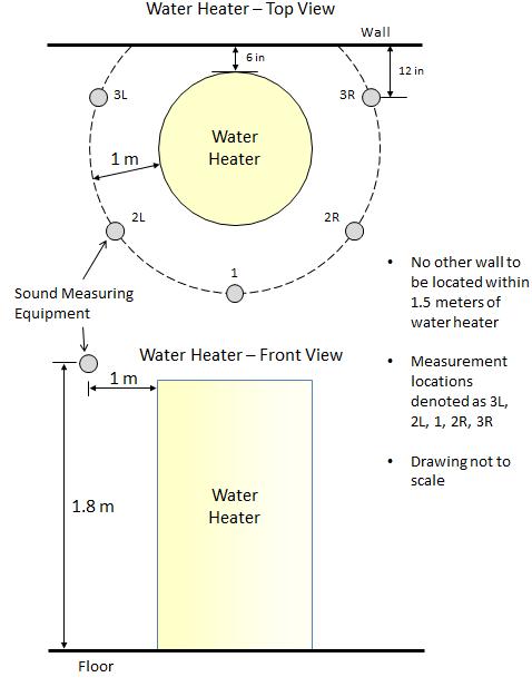
15 Appendix D: Sound Pressure Measurement Test Method Overview: A simplified, repeatable test to measure sound pressure level 1.0 Test setup: The testing room shall approximate a reverberation chamber. The approximate reverberation room is defined as follows: most surfaces are relatively hard - standard laboratory flooring materials such as concrete or linoleum, and cinder block or drywall walls; the room need not be empty of other equipment, though other noise sources should be turned off. Efforts to dampen noise, such as applying anechoic tiles or baffles shall not be done. Measurements made in an anechoic or semi-anechoic style chamber are not valid. The test concept is to approximate a typical garage, basement, or house utility room. Place the water heater 6 away from one wall in the room. o All other walls or objects shall be at least 1.5 meters away from the water heater. o Ambient noise shall be less than or equal to 35dBA. o Unit shall be run without ducting attached for those units where this is an option. Initiate normal water heater operation under an operating mode which uses all moving components simultaneously including, but not limited to, the compressor, fan, or pumps. Allow the unit to operate in this mode for one minute before proceeding and ensure that a steady state of operation is maintained during the entire sound measurement procedure. o Inlet water temperature shall be 58 F ±10 F o Ambient air conditions shall be 67 F ±18 F 2.0 Test procedure: Measure the A-weighted sound pressure level: o At five points 1 meter distant from the water heater surface at 1.8 meter height above the base of the water heater. Points 3L and 3R should be 12 from the wall. o If the water heater has an airflow intake or exhaust flow path around the circumference of the equipment, position the unit, as follows, so the air flow is not directly aimed at a measurement point: aim the intake or exhaust between either points (3L, 2L), (2L, 1), (1, 2R), and/or (2R, 3R). In no case should the flow path be directed towards the wall between points (3L, 3R). Average all five measurements into a single sound value.
16
17 Appendix E: Compressor Cut-off Temperature: Overview: A method to determine the low-end ambient temperature below which the compressor does not operate. The cut-off temperature is used within the Northern Climate Energy Factor calculation. Determine the compressor cutoff temperature to within 5 F corresponding to the following temperature bin centers: 27 F, 32 F, 37 F, 42 F, 47 F, 52, F 57 F, etc. 1.0 Test setup: Set inlet water temperature, Tinlet water, to 50 F. To start the test, establish normal water heater operation with the water heater outlet temperature at a set point of 125 F. Initiate a draw at 3gpm and withdraw a minimum of 10 gallons. More water shall be withdrawn if needed to achieve compressor cut-in. For example, a large capacity storage tank may require more water to be withdrawn to achieve a compressor cut-in depending on the water heater thermostat dead band. 2.0 Test procedure: The ambient conditions shall be varied as necessary to determine the cut-off temperature. To start, the ambient temperature shall be the closest temperature bin center to the cut-off temperature specified by the manufacturer. For example, if the specified cut-off temperature is 45 F, the test shall be started at 47 F. If the compressor does not turn on in response to the draw at the first ambient condition, or fails to completely recover the tank with the compressor only, increase the ambient temperature by 5 F and repeat the test. Repeat this procedure until an ambient condition is achieved under which the compressor operates. All test shall be conducted with an ambient RH of 60%. Record the lowest temperature bin in which the compressor operates. For purposes of calculations in the Northern Climate Energy Factor, the compressor shall be assumed to operate over the entire temperature bin.
18 Appendix F Airflow Measurement Overview: For units with a ducting kit, measure and verify the airflow in a simulated duct system. Per section of the Specification, the equipment shall maintain its nominal airflow, so as not to reduce heat pump performance, when attached to a duct system subject to 0.2 water column of total external static pressure. The external static pressure (ESP), is measured across the complete airflow path of the system. Conceptually, for exhaust ducting, with a typical HPWH, this includes the filter at the air intake, the evaporator coil, the duct attachment kit, the exhaust duct itself, and an end cap. For dualducted systems, this could also include intake ducting and intake air grills. Definitions: Nominal Airflow is the airflow across the evaporator at which the equipment is rated in the UEF67 test. 1.0 Test setup and procedure Each HPWH may have a unique airflow path and, therefore, measurement setup. The setup presented in this section is done so as one possible example. Refer to Figure 2 for a diagram. For specific questions and clarifications contact NEEA. Attach ducting kit to airflow outlet Attach an approximately 6 foot length of straight, round, sheet metal duct to the duct kit at a diameter matching the two. Install an adjustable damper at the outlet end of the duct Insert an airflow measurement station and a static pressure tap in the middle section of the duct. Connect each to a pressure gauge 2.0 Procedure Adjust damper position, to increase ESP to 0.2 w.c. and record the airflow Compare airflow at 0.2 w.c. to nominal airflow. o If airflow at 0.2 w.c. at least 80% of the nominal airflow, the equipment passes the requirement.

19 Figure 2. Example Airflow Measurement Setup
20 Appendix G Demand Response Validation TEST Recommendation shall be provided from BPA, PGE, TVA, Duke, PJM EPRI and USNAP as they develop. Nothing specified other than the physical connection required at this point AC or DC connection as per CTA All product will be compliant with either UL, ETL and or CSA TBA
21 Appendix H Qualification Process The qualification process for the Advanced Water Heater Specification begins when a manufacturer submits the Heat Pump Water Heater Product Assessment Worksheet to the managing agency (currently NEEA). The most current version of this worksheet is at Manufacturers are encouraged to perform their own Advanced Water Heater Specification testing through any third-party EPA-recognized laboratory (see ch_form). In the event that the manufacturer does not perform this testing (and submits an incomplete assessment worksheet), qualification will be delayed until managing agency or the manufacturer performs (If they are self certified and validated by NEEA or its designated managing agency.) the requisite testing. Upon meeting all the requirements for qualification, a product will be added to the Qualified Products List and classified into the appropriate tier level. For the current list, and for a complete description of the current process flow for the qualification process, see
22 Appendix I Disqualification and Re-qualification Process NEEA and/or the managing agency may test a Product at any time to ensure that the Product meets the requirements of the Advanced Water Heater Specification. 1) Products that have previously been qualified to the Specification may no longer qualify, or qualify for a different tier level. This may be the result of re-testing new versions of the product in a lab, or by inspection of the product in the event that certain product features are no longer commercially available that were available at the time of initial qualification. 2) Challenge to Qualified Products: In the event that an entity (manufacturer, regulatory agency or advocacy group) does not believe the test results of a Qualified Product list (QPL) listed product, it may trigger a challenge event. A challenge event consists of the party challenging the results contacting the QPL managing agency (currently NEEA) in writing that potential discrepancies in test results may exist. The managing agency will notify the challenged party in writing and will coordinate a mutually agreeable testing lab for verification testing. Random units will be pulled from distribution and sent to the testing lab. The full cost of doing the test (including procurement, shipping and testing) will be borne by the entity found in error. In the event that a previously qualified product is found to not meet specifications and/or the specified tier level, the product will be delisted and units of the product will need to be pulled from distribution. The cost of pulling inventory from distribution will be the burden of the manufacturer or supplier. 3) In-field testing reveals substantial differences between in-field performance and lab tested performance (greater than 5%). Substantial is here defined as having a material impact on the aggregate performance in the population of products under study, such that the product in aggregate no longer qualifies to meet the minimum tier (Tier 1) of the Specification or qualifies for a different tier. 4) Product safety issues are observed in the field, or otherwise discovered in lab or field testing. In all of the above scenarios, NEEA and/or the managing agency will share the information with the HPWH Program and Technical Workgroups for review. Upon review, NEEA and/or the managing agency may decide to proceed with the disqualification/tier-reclassification, or to proceed no further for reasons such as lab or field testing errors, insufficient confidence in testing results, or administrative errors in the testing process. NEEA and/or the managing agency may request that the manufacturer provide additional information, or perform additional third-party testing, to determine the outcome. Upon deciding to proceed with disqualification/tier-reclassification, NEEA and/or the managing agency shall inform the manufacturer and provide 20 days for a written response from the date of notice. NEEA shall share the written response (if any) with the HPWH Workgroups, gather feedback, make a final decision, and inform the manufacturer of the decision. Once products are disqualified or have been assigned to a different tier, the manufacturer may petition for requalification or assignment to the original tier level. The information
23 provided in the petition (such as updated lab and field tests, manufacturing process or design changes) will be analyzed by NEEA and/or the managing agency and shared with the HPWH Workgroups. At that point a decision will be made and communicated to the manufacturer.
U.S. FIRE DEPARTMENT PROFILE THROUGH 2009
 U.S. FIRE DEPARTMENT PROFILE THROUGH 2009 Michael J. Karter, Jr. Gary P. Stein October 2010 National Fire Protection Association Fire Analysis and Research Division U.S. FIRE DEPARTMENT PROFILE THROUGH
ENERGY STAR Product Specification for Residential Water Heaters. Eligibility Criteria Draft 1 Version 3.0
 ENERGY STAR Product Specification for Residential Water Heaters Eligibility Criteria Draft 1 Version 3.0 1 2 3 4 5 6 7 8 9 10 11 12 13 14 15 16 17 18 19 20 21 22 23 24 25 26 27 28 29 30 31 32 33 34 35
Soybean Form B. Counts & Measurements
 Soybean Form B Counts & Measurements Components of Forecast Row Space Measurements Number of Plants Number of pods/plant Weight of Beans/Pod How is it used? This information + Form A information is used
AVERAGE RADON CONCENTRATION: Test has met minimum EPA sampling duration.
 February 5, 2016 Test Number: 8401-12 Property Inspected: 623 Pine St, Macon, GA 31201 Licensed Radalink Radon Inspector: Test performed for: ACME Home Inspections William Jacobs John Harwell 943 Spring
Property Inspected: 623 Pine St, Macon, GA 31201
 February 5, 2016 Test Number: 8401-12 Property Inspected: 6 Pine St, Licensed Radalink Radon Inspector: ACME Home Inspections John Harwell 994 Magnolia St Phone: Fax: 770 555 1944 770 555 2105 Calibrated:
NEEA Report: Laboratory Assessment of AirGenerate ATI80 Heat Pump Water Heater
 March 21, 2013 REPORT #03212013 NEEA Report: Laboratory Assessment of AirGenerate ATI80 Heat Pump Water Heater Prepared by: Ben Larson Ecotope, Inc. 4056 9 th Avenue NE Seattle, WA 98105 Northwest Energy
AVERAGE RADON CONCENTRATION:
 February 2, 2017 Test Number: 1703-142 Property Inspected: 804 425th street, Joice, IA 50446 Licensed Radalink Radon Inspector: Lupkes Inspections Myron and Jayne Lupkes 804 425th Street Joice, IA 50446
Property Inspected: 1228 Radcliffe Ave, Kingsport, TN 37664
 September 24, 2015 Test Number: 13-175 Property Inspected: 1228 Radcliffe Ave, Kingsport, TN 37664 Licensed Radalink Radon Inspector: Professional Home Inspections Kenneth Bartley Jr. 180 Kincheloe Road
6. Results for the Wholesale and Retail Trade Sectors
 6. Results for the Wholesale and Retail Trade Sectors A total of seven sectors comprise the U.S. horticultural wholesale and retail trade industries: 1) wholesale flower, nursery stock & florist supply;
Home Energy Assessment Rebate Guide
 Home Energy Assessment Rebate Guide 61. Book an initial Home Energy Assessment. STEPS to Energy Savings To book an assessment, visit our website or call us at 1 877 999 6035 to be connected with an Efficiency
Model 8191 & 8192 Ventilator with Dehumidification Installation and Operating Instructions
 Model 8191 & 8192 Ventilator with Dehumidification Installation and Operating Instructions ON/OFF button used to turn the ventilator on and off Up/Down buttons used to change humidity or vent time setting
Model 8191 & 8192 Ventilator with Dehumidification Installation and Operating Instructions
 Model 8191 & 8192 Ventilator with Dehumidification Installation and Operating Instructions ON/OFF button used to turn the ventilator on and off Up/Down buttons used to change humidity or vent time setting
- Residential Fire Sprinkler -
 - Residential Fire Sprinkler - Update as of September 15, 2014 The information provided is a state-by-state status of the 2009 IRC adoption and legislation activities as reported by HBA s. NAHB staff monitors
Verasys System Operation Overview Technical Bulletin
 Contents subject to change. Verasys System Operation Overview Technical Bulletin Code No. LIT-12012370 Issued January 2016 Refer to the QuickLIT Web site for the most up-to-date version of this document.
1.1 DESCRIPTION A. The purpose of this section is to specify Division 23 responsibilities in the commissioning (Cx) process.
 process.") SECTION 239950 MECHANICAL COMMISSIONING SYSTEMS PART 1 - GENERAL 1.1 DESCRIPTION A. The purpose of this section is to specify Division 23 responsibilities in the commissioning (Cx) process. B. Commissioning
SECTION 239950 MECHANICAL COMMISSIONING SYSTEMS PART 1 - GENERAL 1.1 DESCRIPTION A. The purpose of this section is to specify Division 23 responsibilities in the commissioning (Cx) process. B. Commissioning
Heat Pump Water Heater Form
 Heat Pump Water Heater Form All sections must be filled out by the installer at the time of installation. A copy of this completed form, the purchase receipt or invoice, and the manufacturer s Installation
(94'*7 $*89 :2 '*7 ((.,$00 *;.3 *89*7'*7, "$ .3.8-*) &8*2 *39-4:78 ! / )+ $*89-&82 * :2! 8&2 51.3,):7&9.43
 &8*2 *39-4:78 ! / )+ $*89-&82 * :2! 8&2 51.3,):7&9.43") (94'*7 $*89 :2 '*7 ((.,$00 0./&026-1/&$2&% )$&-1&% "%"+)-* "%.--1/&$2.0 3)+%)-'-1/&$2).-1 )$("&+ &12&0#&0'.#&+)" 0)4& %#" 3)+%)-' -4)0.-,&-21 )-$)--"2) >HNMF/ 6BU/ *&(")%)",.., *&(",.("'.*.!1&(*) > 6FQNGWFYJI1
(94'*7 $*89 :2 '*7 ((.,$00 0./&026-1/&$2&% )$&-1&% "%"+)-* "%.--1/&$2.0 3)+%)-'-1/&$2).-1 )$("&+ &12&0#&0'.#&+)" 0)4& %#" 3)+%)-' -4)0.-,&-21 )-$)--"2) >HNMF/ 6BU/ *&(")%)",.., *&(",.("'.*.!1&(*) > 6FQNGWFYJI1
ENERGY STAR Program Requirements Product Specification for Commercial Water Heaters. Eligibility Criteria Version 1.0: Draft 1
 1 2 3 4 ENERGY STAR Program Requirements Product Specification for Commercial Water Heaters Eligibility Criteria Version 1.0: Draft 1 7 8 9 10 11 12 13 14 15 16 17 18 19 20 21 22 23 24 25 26 27 28 29 30
A fresh new offer in home improvement Tuesday 25 August
 A fresh new offer in home improvement Tuesday 25 August We are entering the $24 billion hardware sector The Australian hardware and home improvement sector is worth $24 billion 1 plus Woolworths believes
Changes in NFPA
 Changes in NFPA 72-2002 2002 Oregon Fire Code Committee November 25, 2003 Michael B. Baker, SET Automatic Fire Alarm Association MikeBaker@afaa.org 2003 Michael B. Baker 1 Table of Contents 1. Administration
Installation Guide. Dehumidification. Fresh Air Ventilation. Compact Size. Energy Efficient. RXID-AW90A Whole House Dehumidifier
 RXID-AW90A Whole House Dehumidifier with fresh air ventilation Installation Guide Dehumidification Fresh Air Ventilation Compact Size Energy Efficient The whole house dehumidifier integrates highcapacity
Model 1750A/ 1770A Dehumidifier Installation Instructions
 Model 1750A/ 1770A Dehumidifier Installation Instructions Safety Instructions WARNING 1. Improper installation may cause property damage or injury. Installation, service, and maintenance must be performed
User instructions DHP-AT
 User instructions DHP-AT VUGFC202 If these instructions are not followed during installation and service, Danfoss A/S liability according to the applicable warranty is not binding. Danfoss A/S retains
Esri Roads and Highways & ArcGIS Platform
 Esri Roads and Highways & ArcGIS Platform Increasing efficiency and effectiveness through improved data quality, capture, accessibility, reporting and analytics to transportation agencies Esri Roads and
Equipment Specifications and Required Information Quantity Rebate
 Rebate not to exceed 50% of the cost of equipment. Recycling rebates qualify for the entire rebate, regardless of the recycling cost. Equipment must be purchased or recycled in 2016. Installed equipment
Development Of A Low-Cost Heat Pump Water Heater For Residential Applications
 Development Of A Low-Cost Heat Pump Water Heater For Residential Applications Robert A. Zogg, Arthur D. Little, Inc., Cambridge, MA Edward Barbour, Arthur D. Little, Inc., Washington, DC Brian J. Nowicki,
Fire Sprinklers Working Group Final Report
 Introduction The Building Act received Royal Assent on March 25, 2015. The Act aims to establish more consistent building requirements across British Columbia and create a more robust and modern building
Energy Efficient Options for Residential Water Heating
 Energy Efficient Options for Residential Water Heating Feb 2018 Ben Schoenbauer, Senior Research Engineer Center for Energy and Environment In accordance with the Department of Labor and Industry s statute
NRC REPORTING REQUIREMENTS IN PART 21
 NRC REPORTING REQUIREMENTS IN PART 21 Steven P. Frantz Ryan K. Lighty July 28, 2015 2015 Morgan, Lewis & Bockius LLP Background on 10 C.F.R. Part 21 Part 21 implements Section 206 of the Energy Reorganization
CITY OF DANA POINT. COMMUNITY DEVELOPMENT, BUILDING AND SAFETY Golden Lantern, Suite 209 Dana Point, CA
 CITY OF DANA POINT COMMUNITY DEVELOPMENT, BUILDING AND SAFETY 33282 Golden Lantern, Suite 209 Dana Point, CA 92629 949 248 3594 www.danapoint.org INDOOR AIR QUALITY B011 AIR 2013 CALIFORNIA CODES CODE
SECTION SEQUENCE OF OPERATIONS FOR HVAC CONTROLS
 SECTION 23 09 93 SEQUENCE OF OPERATIONS FOR HVAC CONTROLS PART 1 - GENERAL 1.1 SUMMARY A. This Section includes control sequences for HVAC systems, subsystems, and equipment. B. See Division 23 Section
Product Offering for 2017
 Product Offering for 2017 Accelera 220 E / 300 E Made in EU (Slovakia) 3.05 & 3.39 EF (COP) from Energy Star respectively Updated electronics Displays temperatures and current tank content in Fahrenheit
Imagine TM 6036, 3-piece including roof cap
 KEY BENEFITS COMMON OPTIONS Codes/Standards Applicable ANSI Z124.1.2 CSA B45 Series The MAAX IMAGINE series brings you a roomier shower chamber, a two-way included door, a more spacious shower seat, well-positioned
REFRIGERANT PROCEDURE
 REFRIGERANT PROCEDURE 1. PURPOSE Chlorofluorocarbons contained in some refrigerants are considered to be ozone depleting compounds and therefore damaging to the environment. The Environmental Protection
Heat Exchangers in Swine Facilities
 Heat Exchangers in Swine Facilities Originally published as PIH-124. Authors Larry D. Jacobson, University of Minnesota Martin L. Hellickson, Oregon State University Jay D. Harmon, Iowa State University
EnergyGauge USA Release Notes
 EnergyGauge USA 5.0.02 Release Notes The latest release of EnergyGauge USA, Version 5.0.02, provides new features and bug fixes. This version includes new features for HERS raters. Key features added since
Guidelines for Integrated, Heat Pump Water Heaters in Multifamily Buildings. Rev. July 18, 2018
 Guidelines for Integrated, Heat Pump Water Heaters in Multifamily Buildings Rev. July 18, 2018 Acknowledgments These guidelines were developed through a joint effort between Eversource and Steven Winter
Ventilation for New Low-Rise Residential Buildings July 20, 2015
 Ventilation for New Low-Rise Residential Buildings July 20, 2015 BSC Standard 01 2015 Building Science Corporation 3 Lan Drive, Suite 102 Westford, MA 01886 www.buildingscience.com Contents 1. PURPOSE...3
Installation Instructions
 Installation Instructions PAM3 SERIES PACKAGE AIR CONDITIONERS TABLE OF CONTENTS SAFETY LABELING AND SIGNAL WORDS... 2 UNIT DIMENSIONS... 3 SAFE INSTALLATION REQUIREMENTS... 3 LOCATING THE UNIT... 3 CLEARANCES...
Application of Air Source Variable Refrigerant Flow in Cold Climates
 PREPARED BY Seventhwave with the assistance of Daikin North America, LLC Masters Building Solutions Application of Air Source Variable Refrigerant Flow in Cold Climates A White Paper March 2015 275-1
C-NRPP Quality Assurance Guidance for Radon Test Devices
 C-NRPP Quality Assurance Guidance for Radon Test Devices Table of Contents: 1. Purpose 2. Definitions 3. Quality Assurance Plan 4. Calibration 5. Spikes/Performance Tests 6. Duplicates 7. Blanks 8. Cross-Checks
Address Account # Member # Equipment Specifications Quantity Rebate. ENERGY STAR Appliances
 Rebate not to exceed cost of high efficiency equipment. Equipment must be purchased or recycled in 2015. Installed equipment must be on cooperative's lines. Submit the documentation listed below no later
AVERAGE RADON CONCENTRATION:
 November 23, 2011 Test Number: 1092-192 roperty Inspected: 190 Orchard Heights Drive, South Bend, IN 614 Licensed Radalink Radon Inspector: Certified Home Inspections Dawn Hatfield 19237 Edinburgh Drive
SECTION DIGITAL, ADDRESSABLE FIRE-ALARM SYSTEM
 SECTION 283111 - DIGITAL, ADDRESSABLE FIRE-ALARM SYSTEM PART 1 - GENERAL 1.1 RELATED DOCUMENTS A. Drawings and general provisions of the Contract, including General and Supplementary Conditions and Division
TO THE FOR PRESCRIPTIVE COMPLIANCE OF FOR RESIDENTIAL ALTERATIONS
 TO THE FOR PRESCRIPTIVE COMPLIANCE OF FOR RESIDENTIAL ALTERATIONS The to the 2013 Energy Code for prescriptive compliance for HERS required measures for residential alterations is a guide for those who
EnergyGauge USA Release Notes
 EnergyGauge USA 6.0.00 Release Notes The latest release of EnergyGauge USA, Version 6.0.00 includes 2017 Florida Building Code, Energy Conservation, 6 th Edition performance code and bug fixes. KEY FEATURES
CAN/ULC-S1001, INTEGRATED SYSTEMS TESTING OF FIRE PROTECTION & LIFE SAFETY SYSTEMS Simon Crosby, LEL, CET, CFPS October 21, 2015
 CAN/ULC-S1001, INTEGRATED SYSTEMS TESTING OF FIRE PROTECTION & LIFE SAFETY SYSTEMS Simon Crosby, LEL, CET, CFPS October 21, 2015 Fire Commissioning in Canadian Codes and Standards BACKGROUND Why Commissioning?
Safety and Installation Instructions Model 1700
 Dehumidifier Filter Access Humidity Control Inlet Filter Access Outlet Service Access Port Wiring Access Wire Routing Port Drain On/Off Switch Safety and Installation Instructions Model 1700 INSTALLER
Model 1870F Dehumidifier Installation and Operating Manual
 Model 1870F Dehumidifier Installation and Operating Manual ON/OFF button used to turn dehumidifier on and off Up/Down buttons used to change humidity setting Dehumidifer Control Outlet MODE button used
Healthy Climate Whole-Home Dehumidifier. Nominal Capacity - 70 to 130 pints per day INDOOR AIR QUALITY HCWHD PRODUCT SPECIFICATIONS.
 PRODUCT SPECIFICATIONS INDOOR AIR QUALITY HCWHD Healthy Climate Whole-Home Dehumidifier Bulletin No. 210699 November 2017 Supersedes April 2017 MODEL NUMBER IDENTIFICATION Nominal Capacity - 70 to 130
Ventilation in Humid Climates: Data from Field Experiments
 Gaylord Texan Resort & Convention Center October 20-23, 2004 - Dallas, Texas Ventilation in Humid Climates: Data from Field Experiments Neil Moyer FSEC Yearly Housing Starts Past 3 Years Source: NAHB x
Heat Pump Water Heaters
 Published on Business Energy Advisor (https://snopud.bizenergyadvisor.com) Home > Heat Pump Water Heaters Heat Pump Water Heaters Heat pump water heater (HPWH) systems extract energy content from a heat
ASHRAE JOURNAL ON REHEAT
 Page: 1 of 7 ASHRAE JOURNAL ON REHEAT Dan Int-Hout Chief Engineer Page: 2 of 7 Overhead Heating: A lost art. March 2007 ASHRAE Journal Article Dan Int-Hout Chief Engineer, Krueger VAV terminals provide
Under Section 608 of the CAA, EPA has established regulations (40 CFR Part 82, Subpart F) that:
 that:") Overview Under Section 608 of the CAA, EPA has established regulations (40 CFR Part 82, Subpart F) that: Require service practices that maximize recycling of ozone-depleting compounds (both chlorofluorocarbons
Overview Under Section 608 of the CAA, EPA has established regulations (40 CFR Part 82, Subpart F) that: Require service practices that maximize recycling of ozone-depleting compounds (both chlorofluorocarbons
Fire, Smoke, and Combination Fire Smoke Dampers
 Fire, Smoke, and Combination Fire Smoke Dampers Mark Belke Director Damper Products-Greenheck Chairman of Code Action Review Committee (CARC) California Building Code work group NFPA 80A, 90A, 92B, 101,
Technical Standards for the Air Conditioning and Heat Pump Professional BPI STANDARDS
 Technical Standards for the Air Conditioning and Heat Pump Professional BPI STANDARDS THE SYMBOL OF EXCELLENCE FOR HOME PERFORMANCE CONTRACTORS VERSION 1.1, FEBRUARY 2003 TABLE OF CONTENTS: TECHNICAL STANDARDS
CAN/ULC S Integrated Systems Testing of Fire Protection and Life Safety Systems and Fire Protection Commissioning
 CAN/ULC S1001-11 Integrated Systems Testing of Fire Protection and Life Safety Systems and Fire Protection Commissioning Presentation To: Canadian Fire Alarm Association (CFAA) National Capital Region
Gas-Fired Indoor and Outdoor Duct Furnaces
 July, 2008 Gas-Fired Indoor and Outdoor Duct Furnaces INDOOR GRAVITY VENTED DFG, DBG, DCG INDOOR SEPARATED COMBUSTION DFS, DBS, DCS OUTDOOR GRAVITY AND POWER EXHAUSTED H Series table of contents A complete
LaserFOCUS VLF-250 Engineering Specification
 Vision Fire & Security LaserFOCUS VLF-250 Engineering Specification May 2004 Part Number 20296 LaserFOCUS VESDA 2 VESDA LaserFOCUS Contents Scope...4 Description...4 General...4 Approvals...4 Codes, Standards
Savings Without Sacrifice
 2013 http://waterheatertimer.org/review-ge-heat-pump-water-heater.html GeoSpring Hybrid Water Heater Savings Without Sacrifice 1 / Did you know that residential water heaters are the highest energy users
PROJ. NO SECTION PAGING, SPEAKERS AND HARD-WIRED CLOCK SYSTEMS
 SECTION 26 92 50 PAGING, SPEAKERS AND HARD-WIRED CLOCK SYSTEMS PART 1 - GENERAL 1.1 RELATED DOCUMENTS A. Drawings and general provisions of the Contract, including General and Supplementary Conditions
Consortium for Energy Efficiency
 Consortium for Energy Efficiency Program Collaboration to Drive Market Transformation George M. Chapman Senior Program Manager March 21, 2018 ACEEE Hot Water Forum CEE Today CEE brings together 100 program
CAN/ULC-S1001, INTEGRATED SYSTEMS TEST OF FIRE PROTECTION AND LIFE SAFETY SYSTEMS
 RANDAL BROWN & ASSOCIATES ENGINEERING LTD. CONSULTING ENGINEERS LIFE SAFETY & FIRE PROTECTION 105 6 LANSING SQUARE TORONTO, ONTARIO CAN/ULC-S1001, INTEGRATED SYSTEMS TEST OF FIRE PROTECTION AND LIFE SAFETY
B. Use UT Austin specifications and equipment schedule format for HVAC equipment where available.
 PART 1: GENERAL 1.01 General Requirements A. This standard is intended to provide useful information to the Professional Service Provider (PSP) to establish a basis of design. The responsibility of the
WASHINGTON COUNTY OREGON
 WASHINGTON COUNTY OREGON LONG RANGE PLANNING DIVISION North Bethany Subarea Stream Corridors: Existing Regulations In Oregon, there is a distinct difference between the land use rules that apply in rural
Reviewing HVAC Designs for Compliance with ACCA Manual S
 Reviewing HVAC Designs for Compliance with ACCA Manual S by Wes Davis An approved code change to the 2009 International Residential Code (IRC) clarifies an existing requirement for sizing HVAC equipment:
Signing Up... 1 Logging in for the First Time... 2 The Search Panel... 3
 A Guide to Using TABLE OF CONTENTS Signing Up... 1 Logging in for the First Time... 2 The Search Panel... 3 Keywords... 3 Type... 3 Location... 3 Current Status... 3 On Site... 3 Commencement Received...
MR3CCUHV Temperature/Defrost Control
 Master Catalog 125 Temperature Controls Section A Product/Technical Bulletin Issue Date 0401 MR3CCUHV Temperature/Defrost Control The MR3CCUHV Temperature/Defrost Control is designed to control the temperature
Industrial Space Heating Direct Gas-Fired Heating. Greenheat 50/50 Recirculation
 Industrial Space Heating Direct Gas-Fired Heating Greenheat 00% Outdoor Air Greenheat 50/50 Recirculation 80/0 Recirculation March 008 Product Overview Industrial Space Heating Greenheck s space heating
CAN/ULC-S INTEGRATED SYSTEMS TESTING OF FIRE PROTECTION AND LIFE SAFETY SYSTEMS
 2013 Randal Brown & Associates Engineering Ltd. 1 RANDAL BROWN & ASSOCIATES ENGINEERING LTD. CONSULTING ENGINEERS LIFE SAFETY & FIRE PROTECTION 105 6 LANSING SQUARE TORONTO, ONTARIO CAN/ULC-S1001-11 INTEGRATED
ATTACHMENT D #1 - HVAC (OIL) - SINGLE FAMILY DWELLINGS Category C: OIL
 - SINGLE FAMILY DWELLINGS Category C: OIL") LINE ITEM # ATTACHMENT D #1 - HVAC (OIL) - SINGLE FAMILY DWELLINGS Category C: OIL LINE ITEM DETAIL Labor Material FURNACE COMPONENTS 1 Furnish & Install Sight-Impaired Thermostat For Heating and Cooling
LINE ITEM # ATTACHMENT D #1 - HVAC (OIL) - SINGLE FAMILY DWELLINGS Category C: OIL LINE ITEM DETAIL Labor Material FURNACE COMPONENTS 1 Furnish & Install Sight-Impaired Thermostat For Heating and Cooling
INDOOR AIR QUALITY CCWH Complete Comfort Whole-Home Dehumidifier ENGINEERING DATA. Nominal Capacity - 65 to 135 pints per day CCWH - 090
 ENGINEERING DATA INDOOR AIR QUALITY CCWH Complete Comfort Whole-Home Dehumidifier Bulletin No. CCWH (08/2011) CCWH-065 CCWH-090 CCWH-135 ENERGY STAR Rating for CCWH-065 Model Only Nominal Capacity - 65
Field Evaluation of Pre-Commercial Residential Gas Heat Pump Water Heaters
 Field Evaluation of Pre-Commercial Residential Gas Heat Pump Water Heaters Paul Glanville ACEEE Hot Water Forum Monday, February 22 nd, 2016 Portland, OR Gas Heat Pump Water Heater Why? Motivation: Despite
INSTALLATION INSTRUCTIONS WALL MOUNTED PACKAGE AIR CONDITIONERS WA121
 INSTALLATION INSTRUCTIONS WALL MOUNTED PACKAGE AIR CONDITIONERS Model: WA121 Bard Manufacturing Company Bryan, Ohio 43506 Since 1914...Moving ahead just as planned. Manual : 2100-234 G Supersedes: 2100-234
Substation Monitoring System
 Substation Monitoring System SF6 Gas Density Monitoring System Description Introduction As a result of recent European legislation on the control of greenhouse gasses, utilities and manufacturers alike
Supplier Handbook. InSinkErator st Street Racine, WI
 Supplier Handbook InSinkErator 4700 21st Street Racine, WI 53406 262-554-5432 Table of Contents SECTION 1: Introduction... 2 1.1 InSinkErator... 2 1.2 InSinkErator Expectations for a Suppliers Quality
HEALTHY HOME SYSTEM CONTROL Plus Model: HHSC+
 HEALTHY HOME SYSTEM CONTROL Plus Model: HHSC+ The Field Controls Healthy Home System Controller Plus (HHSC+) is designed to work in conjunction with the forced air HVAC system to periodically introduce
University Design Standard Fire Alarm Systems
 1.0 Overview University Design Standard Fire Alarm Systems This document provides Virginia Tech s standards for the design and installation of fire alarm systems and equipment in new construction, retrofit
Published by the California Building Performance Contractors Association
 TO THE FOR PRESCRIPTIVE COMPLIANCE OF FOR RESIDENTIAL ALTERATIONS The to the 2008 Energy Code for prescriptive compliance for Refrigerant Charge & Airflow for residential alterations is a guide for those
Continuing Education Units (CEU)
") CEUGuide Continuing Education Units (CEU) You are responsible for meeting any CEU requirements which may apply to your professional work in the low voltage industry. It is your responsibility to identify
CEUGuide Continuing Education Units (CEU) You are responsible for meeting any CEU requirements which may apply to your professional work in the low voltage industry. It is your responsibility to identify
Uniform Dwelling Code 2017 Updates SPS 323
 Uniform Dwelling Code 2017 Updates SPS 323 Lenny Kanter UDC Engineering Consultant Department of Safety and Professional Services 608 261 6541 voice 608 267 9723 fax robert.kanter@wi.gov Plan Review and
Pellet Stove Test Manual
 Pellet Stove Test Manual Stricter Emission Standards Adopt stricter emission standards than the EPA. 1. Washington: 4.5 grams per hour for non-catalytic and pellet stoves; 2.5 grams per hour for catalytic
OPERATION INSTRUCTIONS DEMAND DEFROST CONTROL BOARD MODEL FOR USE WITH MODELS: AFFINITY, ECHELON, ACCLIMATE HEAT PUMP SERIES
 OPERATION INSTRUCTIONS DEMAND DEFROST CONTROL BOARD MODEL 500644 FOR USE WITH MODELS: AFFINITY, ECHELON, ACCLIMATE HEAT PUMP SERIES A047-001 FIGURE 1: Demand Defrost Control Module ANTI-SHORT CYCLE DELAY
Summary of 60-Day Notice: Heating Efficiency
 Notification Date: November 5, 2015 Summary of 60-Day Notice: Heating Efficiency Public Service Company of Colorado ( the Company ) posts this 60-Day Notice to add a new measure to the Heating Efficiency
OPERATING & MAINTENANCE MANUAL HORIZONTAL WATER SOURCE HEAT PUMP. World class comfort.
 OPERATING & MAINTENANCE MANUAL HORIZONTAL WATER SOURCE HEAT PUMP World class comfort. welcome Congratulations on your selection of Ice Air Water Source Heat Pumps (WSHPs) for your comfort conditioning
TEC210x-2 Series Networked Thermostats
 Product Bulletin Issue Date February 1, 2005 TEC210x-2 Series Networked Thermostats The TEC210x-2 Series of thermostats is a family of highly advanced thermostats specifically designed for control of equipment
Daikin ENVi Thermostat installation overview
 Daikin ENVi Thermostat installation overview RESIDENTIAL LIGHT COMMERCIAL COMMERCIAL Presenter s Name Presenter s Title Daikin ENVi system overview (web based thermostat) Slide 2 Daikin ENVi System Overview
UNIVERSITY OF MISSOURI Heating Ventilating and Air-Conditioning (HVAC) 2016 Q1
 2016 Q1") GENERAL: This section provides general standards for overall sizing and design of Heating, Ventilating, and Air Conditioning (HVAC) systems. Other sections contain specific standards for each system per
GENERAL: This section provides general standards for overall sizing and design of Heating, Ventilating, and Air Conditioning (HVAC) systems. Other sections contain specific standards for each system per
SMART DUCT SYSTEM. Caution: Do not tamper with the unit or its controls. Call a qualified service technician.
 SMART DUCT SYSTEM Caution: Do not tamper with the unit or its controls. Call a qualified service technician. Manufactured by: Industries Dettson inc. 3400 Industrial Boulevard Sherbrooke, Quebec - Canada
P/N f. HomeWorks QS Palladiom Thermostat Configuration Guide
 HomeWorks QS Palladiom Thermostat Configuration Guide Table of Contents Description...4 Step : Identify the HVAC Equipment and Confirm Device Installation...5 Identify the HVAC Equipment...5 Confirm Device
COMcheck Software Version Mechanical Compliance Certificate
 COMcheck Software Version 3.8.2 Mechanical Compliance Certificate 90.1 (2007) Standard Section 1: Project Information Project Type: New Construction Project Title : Rudy's Star Motors Construction Site:
API MANUAL OF PETROLEUM MEASUREMENT STANDARDS
 API MANUAL OF PETROLEUM MEASUREMENT STANDARDS Chapter 22 Testing Protocols Section 1 General Guidelines for Developing Testing Protocols for Devices Used in the Measurement of Hydrocarbon Fluids Type Testing
Consumer s Guide To Radon Reduction How to fix your home
 EPA 402/K-10/002 January 2010 www.epa.gov/radon Consumer s Guide To Radon Reduction How to fix your home Indoor Air Quality (IAQ) Overview Reduce Radon Levels In Your Home Radon is the second leading cause
TRACE 700. Slide 1. Hello, my name is Nick Cavitt and I m a marketing engineer in the C.D.S. group at TRANE.
 Slide 1 TRACE 700 Chiller Sequencing and Controls Hello, my name is Nick Cavitt and I m a marketing engineer in the C.D.S. group at TRANE. Today, we will be talking about the Plant Sequencing and Controls
Model 1850F Dehumidifier Installation and Operating Manual
 Model 1850F Dehumidifier Installation and Operating Manual ON/OFF button used to turn dehumidifier on and off Up/Down buttons used to change humidity setting Dehumidifer Control Outlet MODE button used
Ventilation Techniques. Topic 5 - Audio 53
 Topic 5 - Audio 53 Increasing Fresh Air Increasing fresh air make-up to a building can dilute radon and other indoor air contaminants. Increasing make-up air can reduce the negative pressures within a
SAFETY AND INSTALLATION MANUAL MODEL 8100
 SAFETY AND INSTALLATION MANUAL ENERGY RECOVERY VENTILATORS MODEL 8100 Provides year-round fresh air Recovers 77% of the apparent heating or cooling energy from the exhausted air See Warnings Page 3 Table
 ZIP Economizer Method of Operation Sequence of Operation States Virgin State The ZIP Economizer comes shipped from the factory in this state. Setup Incomplete will be displayed. No control will occur until
DAY/TIME Button: Selects hour, minute and day setting.
 MODEL 5300 USER MANUAL READ ALL INSTRUCTIONS BEFORE PROCEEDING For more information on energy savings, go to www.energystar.gov Premier Series Universal Auto Changeover Thermostat Up to 2 Heat / 2 Cool
TANKLESS WATER HEATER HEATING SOLUTIONS
 TANKLESS WATER HEATER HEATING SOLUTIONS 2017 Rinnai America Corporation. The material contained in this course was researched, assembled, and produced by Rinnai America Corporation and remains their property.