AHU-KIT SERVICE MANUAL
|
|
|
- Kellie Kelly
- 5 years ago
- Views:
Transcription

1 AHU-KIT SERVICE MANUAL T1/R410A/50-60Hz (GC І )
 For the safe operation of this unit, please read and follow the instructions carefully.")
 Direct operators or maintainers should well keep this manual.")
2 Preface For correct installation and operation, please read all instructions carefully. Before reading the instructions, please be aware of the following items: (1) For the safe operation of this unit, please read and follow the instructions carefully. (2) During operation, total capacity of indoor units should not exceed the total capacity of outdoor units. Otherwise, poor effect of cooling or heating may result. (3) Direct operators or maintainers should well keep this manual. (4) If this unit fails to operate normally, please contact our service center as soon as possible and provide the following information: Content on the nameplate (model number, cooling capacity, production code, ex-factory date). Malfunction details (before and after the malfunction occurs). (5) Each unit has been strictly tested and proved to be qualified before ex-factory. In order to prevent units from being damaged or operating normally because of improper disassembly, please do not disassemble the unit by yourself. If you need to disassemble and check units, please contact our service center. We will send specialists to guide the disassembly. (6) Do only use this system in combination with a field supplied air handling unit. Do not connect this system to other appliances. (7) The outdoor unit and the air handling unit can both influence the overall performance of the unit, please be sure to select appropriate outdoor unit, air handling unit and AHU-KIT unit according to actually apply requirements. (8) This equipment is not designed for year-round cooling applications with low indoor humidity conditions, such as Electronic Data Processing rooms. (9) All graphics in this manual is only for your reference. For sales or production reasons, these graphics are subject to change by manufacturer without prior notice. User Notice This appliance can be used by children aged from 8 years and above and persons with reduced physical, sensory or mental capabilities or lack of experience and knowledge if they have been given supervision or instruction concerning use of the appliance in a safe way and understand the hazards involved. Children shall not play with the appliance. Cleaning and user maintenance shall not be made by children without supervision. Disposal This marking indicates that this product should not be disposed with other household wastes throughout the EU. To prevent possible harm to the environment or human health from uncontrolled waste disposal, recycle it responsibly to promote the sustainable reuse of material resources. To return your used device, please use the return and collection systems or contact the retailer where the product was purchased. They can take this product for environmental safe recycling.
3 Contents Chapter One: Product Introduction Product Specification Product Profile Key Parts Name Basic Principle Sketch Map of System Connection Basic Parameters... 2 Chapter Two: Control Part DISPLAY LCD OF WIRED CONTROLLER LCD DISPLAY INSTRUCTION BUTTONS BUTTON GRAPHICS FUNCTION INSTRUCTION OF BUTTONS... 8 Chapter Three: Installation Parts Preparations for Installation Before Installation Standard Fittings Selecting the Air Handling Unit Selecting the AHU-KIT Unit Location for Installation Requirements for Communication Wire Wiring Requirements Installation Instructions Unit Dimensions and Maintenance Space Piping Installation EXV Installation Installation of the Control Box Installation of the Thermistors Installation of the EXV Cable Installation of Wired Controller Wire Connection Connect Cables and Terminals of Wiring Board Power Cord Connection Connection of Communication Wire between Indoor Unit and Outdoor Unit (or Indoor Unit) Connect Communication Wire of Wired Controller Illuminate for Connection of Wired Controller and Indoor Units (AHU-KIT) Network Chapter Four: Debugging Operation Before Operation Test Operation Chapter Five: Maintenance Part Table of Error Codes for Indoor Unit Troubleshooting Routine Maintenance Maintenance Before the Seasonal Use Maintenance After the Seasonal Use Disposal Requirements... 31

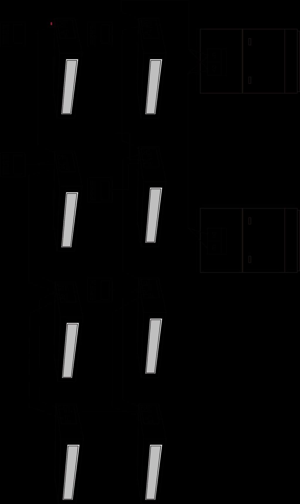
4 Chapter One: Product Introduction 1. Product Specification 1.1 Product Profile AHU-KIT is an air conditioning product developed by Gree, which is used for connecting outdoor unit of VRF and combine unit, making the outdoor unit of VRF as the cold source and heat source. Each AHU-KIT includes an electronic expansiaon vavle box and a control box. This product is mainly applicable for business building, restaurant, supermarket, cinema, exhibition center, gymnasium, shopping mall, hotel, office bulding and big/medium scale public building. 1.2 Key Parts Name 2. Basic Principle NO. 1 2 Name Control box Electronic expansion valve box 2.1 Sketch Map of System Connection 1
5 3. Basic Parameters Model GMV-N140U/A-T GMV-N280U/A-T GMV-N560U/A-T Product Code CN750N0030 CN750N0020 CN750N0010 Power V/Ph/Hz 220~240/1/50 & 208~230/1/60 Defaulted capacity of ex-factory Adjustable capacity Cooling kw Heating kw Cooling kw 9/11.2/ /28 45/50.4/56 Heating kw 10/12.5/16 25/ /56.5/62.5 Power W Size of connection pipe Outline dimension (WⅹDⅹ H) Liquid pipe mm Φ9.52 Φ9.52 Φ12.7/Φ15.9/Φ 15.9 Gas pipe mm Φ15.9 Φ19.05/Φ22.2 Φ28.6 Connection method Brazing Connection Brazing Connection Brazing Connection Electronic expansion valve box mm Control box mm Packing size(wⅹdⅹh) mm Net weight/gross weight kg 8.6/ / /15.5 Loading 40'GP set 'HQ set Note: 1The parameters of the unit is subject to changed without prior notice due to improvement product. Please refer to the nameplate. 2 Combination method of the unit: one-to-one, one-to-more, and mixed connection. One-toone for 560 model; mixed connection and one-to-more for 140 model and 280 model. (1) Below models can be connection to the same outdoor unit syste with the indoor unit of general VRF unit AHU-KITmodle GMV-N140U/A-T Model of outdoor unit Can connect to modular outdoor unit of GMV-**WM/* series. The total capacity for AHU and the indoor unit of general air conditioenr should be 50%~100% of capacity of outdoor unit. The capacity of connected GMV-N280U/A-T AHU can t be more than 30% of the outdoor unit. AHU-KIT can be used independently. The total capacity of connected AHU should be 50%~100% of capacity of outdoor unit. Note: When connecting AHU-KIT with the indoor unit of VRF unit, it must comply with the capacity requirement. The capacity of AHU can be more than 30% of capacity of outdoor unit and the capacity of indoor unit should be within 50%~100%. Otherwise, it may affect the operation, or enven damage the unit. 2

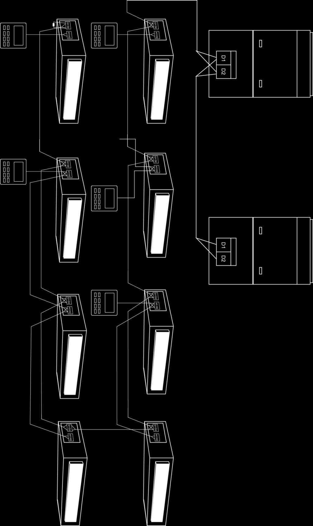
6 Sketch map for the connection of AHU-KIT and indoor unit of general VRF unit (2) AHU-KIT in below table can only be connected by the fixed combination method AHU-KIT model Model of outdoor unit GMV-N140U/A-T GMV-140WL/A-T GMV-140WL/A-X GMV-N280U/A-T GMV-280WM/* GMV-N560U/A-T GMV-280WM/* 2sets 3


7 Sketch map for the connection of GMV-N140U/A-T and GMV-N280U/A-T Sketch map for the connection of GMV-N560U/A-T 4


8 Chapter Two: Control Part 1.DISPLAY Fig. 1.1 Appearance of wired controller 1.1 LCD OF WIRED CONTROLLER Fig. 1.2 LCD graphics of wired controller 5
9 1.2 LCD DISPLAY INSTRUCTION Table 1.1 LCD display instruction No. Symbols Instructions 1 Up and down swing function 2 Left and right swing function It's valid under Save mode and displays during setting process. Temperature lower limit for Cooling: Limit the minimum temperature value under Cooling or Dry mode.temperature upper limit for Heating: Limit the maximum temperature value under Heating, Space Heating or 3D Heating mode. Auto mode (Under Auto mode, the indoor units will automatically select their operating mode as per the temperaturechange so as to make the ambient comfortable.) It shows the setting temperature value(in case the wired controller is controlling a Fresh Air Indoor Unit, then thetemperature zone will display FAP) 6 Cooling mode 7 Dry mode 8 Fan mode 9 Heating mode 10 When inquiring or setting project number of indoor unit, it displays "NO." icon 11 * Floor Heating mode (When Heating and Floor Heating simultaneously shows up, it indicates 3D Heating is activated.) 12 Display "SET" icon under parameter setting interface 13 - Space Heating mode 14 Display "CHECK" icon under parameter view interface 15 Outdoor unit operates under Save mode/upper limit of system capacitor less 100%/remote Save status 16 Sleep status 17 Current set fan speed (including auto, low speed, medium-low speed, medium speed, medium-high speed, high speedand turbo seven status) 18 Air status, Indoor unit optional function 6
10 No. Symbols Instructions 19 Remind to clean the filter 20 Quiet status (including Quiet and Auto Quiet two status) 21 Allow auxiliary electric heating On icon 22 Light On/Off function 23 X-fan function 24 Health function, Indoor unit optional function 25 Reserved function 26 Out function 27 Outdoor unit defrosting status 28 Gate-control function 29 Shielding status 30 Child Lock status 31 One wired controller controls multiple indoor units 32 Save status of indoor unit It indicates the current wired controller is the slave wired controller (address of wired controller is 02) Memory status (The indoor unit resumes the original setting state after power failure and then power recovery) 35 Invalid operation 36 Current wired controller connects master indoor unit 37 Timer zone:display system clock and timer status 7
 Set operating temperature of indoor unit 2 (2) Set Timer 5 (3) Switch Quiet mode, Air grade, Clean grade, set upper and lower")

11 2.BUTTONS 2.1 BUTTON GRAPHICS Fig. 2.1 Button graphics 2.2 FUNCTION INSTRUCTION OF BUTTONS Table 2.1 Function instruction of buttons No. Buttons Instructions 1 ENTER/CANCEL Select and cancel function (1) Set operating temperature of indoor unit 2 (2) Set Timer 5 (3) Switch Quiet mode, Air grade, Clean grade, set upper and lower temperature limit under Save mode (4) Set and inquiry parameter 3 SLEEP Set Sleep mode 4 FAN 6 MODE 7 FUNCTION Switch among auto, low speed, low-medium speed, medium speed, medium-high speed, high speed and turbo status Switch Auto,Cooling, Dry, Fan, Heating, Floor Heating, 3D Heating and Space Heating modes for indoor unit. (Note: The Floor Heating, 3D Heating and Space Heating function icon will show up when the unit has those functions.) Switch among Air, Quiet, Light, Health, Out, Save, Clean, E-heater and X-fan functions. 8 TIMER Timer setting 9 SWING Set up and down swing status 10 ON/OFF Indoor unit On/Off Simultaneously press and for 5s to enter or cancel the Child Lock function. 8
12 Chapter Three: Installation Parts 1. Preparations for Installation 1.1 Before Installation Product graphics are only for reference. Please refer to actual products. Unspecified measure unit is mm. (1) This equipment is designed for R410A system, and the designed working pressure is 4.2 MPa or 42 bar. (2) Precautions for R410A: The refrigerant requires strict cautions for keeping the system clean, dry and tight. Clean and dry:foreign materials (including mineral oils or moisture)should be prevented from getting mixed into the system. Tight:Read this manual carefully and follow these procedures correctly. Since R410A is a mixed refrigerant, the required additional refrigerant must be charged in its liquid state. (If the refrigerant is in state of gas, its composition changes and the system will not work properly). The connected air handling units must have heat exchangers designed exclusively for R410A. (3) Never use this appliance under inflammable and explosive gas. (4) For the following items, take special care during construction and check after installation is finished: 1.2 Standard Fittings Tick when checked Are the thermistors fixed firmly? Thermistor may come loose. Is the capacity code setted correctly? The performance of system may not achieve it s requirement. Is the control box fixed firmly? The unit may drop, vibrate or make noise. Do electrical connections comply with specifications? The unit may malfunction or components may burn out. Are wiring and piping correct? The unit may malfunction or components may burn out. Is the unit safely grounded? Dangerous at electric leakage. Please use the supplied standard fittings listed below as instructed. 1.3 Selecting the Air Handling Unit Please use the supplied standard fittings listed below as instructed. 9

 Allowable internal volume of heat exchanger (dm 3 ) Allowable capacity of heat exchanger (kw) Minimum Maximum Minimum Maximum Suggested")
13 No. Name Appearance Quantity 1 Magnetic ring Swell screw 4 3 Self-tapping screw 4 4 Bundle 1 5 Operating Instruction Manual 1 6 Operating Instruction Manual (Unitary Page) 1 7 Wired controller 1 Select the air handling unit according to the technical data and limitations mentioned in the following table. Lifetime of the outdoor unit, operation range or operation reliability may be influenced if you neglect these limitations. Model GMV-N140U/A-T GMV-N280U/A-T GMV-N560U/A-T capacity (kw) Allowable internal volume of heat exchanger (dm 3 ) Allowable capacity of heat exchanger (kw) Minimum Maximum Minimum Maximum Suggested air volume (m 3 /h) ~ ~ ~ ~ ~ ~ ~ ~ The capacity of heat exchanger is obtained at these test conditions: evaporation temperature at air outlet of heat exchanger is 6, overheating degree of heat exchanger is 5 and the air return temperature is 27 DB/19 WB. 2 The heat exchanger of air handling unit is designed for R410A, and it s working pressure is 4.2MPa. 3 Quantity of rows of heat exchanger: no more than 4 rows. 4 The diameter of copper pipe of heat exchanger is no more than 12.7mm. 9.52mm is recommended. The air handling unit can be connected as a standard indoor unit to the outdoor unit. The limitations of connection are determined by the outdoor unit. 1.4 Selecting the AHU-KIT Unit The corresponding AHU-KIT unit needs to be selected for your air handling unit. Select the AHU-KIT unit according to the above limitations. 10
14 Capacity ranges of different AHU-KIT unit are as follows: Acquiescent capacity Adjustable capacity Model (kw) (kw) GMV-N140U/A-T /11.2/14.0 GMV-N280U/A-T /28 GMV-N560U/A-T /50.4/56 Different capacities of same model of AHU-KIT unit are achieved through dialing capacity code of mainboard (shown as "S1").Capacity code setting is shown as follows: S Capacity (kw) Please ensure dialing the code switch properly in place instead of middle position. Setting the switch to "ON" stands for "0", otherwise stands for "1". ( The black part is the deflector rod.) The figure shows that the addresses of 1,2,3,4,5 are 0,0,1,0,0. (1) The selected air handling unit must be designed for R410A. (2) Extraneous substances (including mineral oils or moisture) must be prevented from getting mixed into the system. 1.5 Location for Installation Select an installation site where the following conditions are fulfilled and that meets your customer s approval. (1) The EXV box can be installed inside and outside. The control box should be installed inside. (2) Do not install the EXV box in or on the outdoor unit. (3) Do not put the option boxes in direct sunlight. Direct sunlight will increase the temperature inside the option boxes and may reduce its lifetime and influence its operation. (4) Choose a flat and strong mounting surface. (5) Make sure there is enough free space in front and in the side of the AHU-KIT unit for future maintenance. 11
 Keep the air handling unit, power supply wiring and transmission wiring at least 1 m away from televisions and radios.")
15 (6) The installation site should be far away from heat source, inflammable gas and smoke. (7) Keep the air handling unit, power supply wiring and transmission wiring at least 1 m away from televisions and radios. This is to prevent image interference and noise in those electrical appliances. (Noise may be generated depending on the conditions under which the electric wave is generated, even if 1 m is kept.) (8) Make sure the electronic expansion valve is installed in an upright position. Notes! (1) Do not install or operate the unit in rooms mentioned below: a) Where mineral oil, like cutting oil is present. b) Where the air contains high levels of salt such as air near the ocean. c) Where sulphurous gas is present such as that in areas of hot spring. d) In vehicles or vessels. e) Where voltage fluctuates a lot such as that in factories. f) Where high concentration of vapor or spray are present. g) Where machines generating electromagnetic waves are present. h) Where acidic or alkaline vapor is present. (2) Installing this unit must comply with the relevant local and national codes. (3) Connecting the power after all installation works are done. 1.6 Requirements for Communication Wire If the unit is installed in the place with strong electromagnetic interference, shielded wire must be applied on the communication wire between indoor unit (AHU-KIT) and wired controller. Twisted pair wire with shielding function must be applied on the communication wire between indoor unit and indoor unit (outdoor unit) Selecting communication wire for AHU-KIT and wired controller Wire Type Light/Common PVC Jacket Soft Wire Light shield/common PVC Jacket Soft Wire Total Length of Communication wire L(m) L 250 L 250 Fig.3.1 Wire Gauge (mm 2 ) ~ ~ Wire Standard GB/T GB/T Remark The total length of communication wire should not exceed 250m. The shield cable is required when the unit is installed in the environment of strong magnetic or interference. 12
 L 1000 2 0.75 L 1000 2 0.75 1.")
16 1.6.2 Select Communication wire for AHU-KIT and Outdoor Unit Wire Type Light/Common PVC Jacket Soft Wire Light shield/common PVC Jacket Soft Wire Total Length of Communication wire L(m) Fig.3.2 Wire Gauge (mm 2 ) L L Wiring Requirements Power Cord Size and Air Switch Capacity: Model GMV-N140U/A-T GMV-N280U/A-T GMV-N560U/A-T Power Cord Size 220~240V/1ph/50Hz & 208~230V/1ph/60Hz Air Switch Capacity(A) Wire Standard GB/T GB/T Ground Wire Minimum Sectional Area(mm 2 ) Remark If wire gauge is 2X1 mm 2, then it s OK to increase the length of communication wire. But total length should not exceed 1500m. The shield cable is required when the unit is installed in the environment of strong magnetic or interference. Power Cord Minimum Sectional Area(mm 2 ) (1) Use copper wire only as unit s power cord. Operating temperature should be within its rated value. (2) Above selection requirements: Power cord size is based on BV single-core wire (2~4pc) at 40 Cambient temperature when laying across plastic pipe (GB/T ). Air switch is D type and used at 40 C. If actual installation condition varies, please lower the capacity appropriately according to the specifications of power cord and air switch provided by manufacturer. (3) Install cut-off device near the unit. The minimum distance between each stage of cut-off device should be 3 mm (The same for both indoor unit and outdoor unit). 13
Size of control box for GMV-N140U/A-T GMV-N280U/A-T and GMV-N560U/A-T (Unit: mm):")
17 2. Installation Instructions 2.1 Unit Dimensions and Maintenance Space (1)Size of control box for GMV-N140U/A-T GMV-N280U/A-T and GMV-N560U/A-T (Unit: mm): Maintenance space of control space (Unit: mm): (2)Size of EXV box for GMV-N140U/A-T and GMV-N280U/A-T(Unit: mm): 14

:")

18 Size of EXV box for GMV-N560U/A-T (Unit: mm): Maintenance space of EXV box (Unit: mm): 15

19 2.2 Piping Installation Diagram of Piping Connection 1. Air handling unit 2. Connection pipe from expansion valve kit to air handling unit 3. Valve kit 4. Liquid pipe 5. Gas pipe A: When the air handling unit is installed at the top of the EXV box, vertical distance between the bottom of the air handling unit to the EXV box is no more than 2 m; if the air handling unit is installed under the EXV box, vertical distance between the bottom of the air handling unit to the EXV box is no more than 2 m. L: The length of liquid pipe between the air handling unit to EXV box is no more than 2 m. L is to be considered as a part of the total maximum piping length. See installation manual of the outdoor unit for piping installation Piping Connections class. Make sure to install gas and liquid pipe diameters in function of the air handling unit capacity (*)Note: Model Capacity(kW) Gas pipe(mm) GMV-N140U/A-T GMV-N280U/A-T GMV-N560U/A-T 16 Connection pipe Liquid pipe(mm) 9.0 Φ15.9 Φ Φ15.9 Φ Φ15.9 Φ Φ19.05 Φ Φ22.2 Φ Φ28.6 Φ12.7(*) 50.4 Φ28.6 Φ Φ28.6 Φ15.9 The internal diameter of both inlet tube and outlet tube of EXV box for GMV-N560U/A-T is Φ16.3. It needs engineering treatment on the scene if you want to connect liquid pipe of Φ12.7( expanding the copper tube of Φ12.7 or using a connection copper tube) in order to satisfy the clearance requirement of brazing(the clearance requirement is 0.1~0.2mm normally) Selection of Piping (1) Ensure the inside of the pipes is clean and no foreign materials.
 1.2 1/2H Φ28.6(9/8) 1.2 1/2H Φ31.8(5/4) 1.3 1/2H Φ34.90(11/8) 1.3 1/2H Φ38.10(12/8) 1.5 1/2H Φ41.30(13/8) 1.5 1/2H Φ44.5(7/4) 1.5 1/2H Φ51.4(7/4) 1.5 1/2H Φ54.1(17/8) 1.5 1/2H 2.2.4 Cautions for Brazing (1) Make sure there is nitrogen protection during welding.")
20 (2) Pipe specifications: R410A System Pipe Φ(mm/inch) Thickness(mm) Temper grade of piping material Φ6.35(1/4) 0.8 O Φ9.52(3/8) 0.8 O Φ12.70(1/2) Φ15.9(5/8) Φ19.05(3/4) Φ22.2(7/8) 1.2 1/2H Φ25.40(1/1) 1.2 1/2H Φ28.6(9/8) 1.2 1/2H Φ31.8(5/4) 1.3 1/2H Φ34.90(11/8) 1.3 1/2H Φ38.10(12/8) 1.5 1/2H Φ41.30(13/8) 1.5 1/2H Φ44.5(7/4) 1.5 1/2H Φ51.4(7/4) 1.5 1/2H Φ54.1(17/8) 1.5 1/2H Cautions for Brazing (1) Make sure there is nitrogen protection during welding. Brazing without carrying out nitrogen replacement or releasing nitrogen into the piping will create large quantities of oxidized film on the inside of the pipes, adversely affecting valves and compressors in the refrigerating system and preventing normal operation. (2) When brazing while inserting nitrogen into the piping, nitrogen must be set to 0.02 MPa with a pressure-reducing valve (=just enough so that it can be felt on the skin). 1. Refrigerant piping 2. Part to be brazed 3. Taping 4. Hands valve 5. Pressure-reducing valve 6. Nitrogen (3) For details, see manual of the outdoor unit. 1 All field piping must be provided by a licensed refrigeration technician and must comply with the relevant local and national codes. 2 The EXV box is required to be installed in a vertical direction within the range of 90±15 (not allowed for horizontal work). Welding the connection tubes first before refrigerant pipes in order to avoid face-down soldering. a. For refrigerant piping of outdoor unit, refer to the installation manual supplied with the outdoor unit. b. The maximum allowed piping length depends on the connected outdoor model. 17
 Drill 4 holes on correct position (measurements as indicated in figure below) and fix the valve kit box securely with 4 screws through the provided holes Ø12 mm.")
21 2.3 EXV Installation Mechanical Installation (1) Remove the EXV box cover by unscrewing screws. (2) Drill 4 holes on correct position (measurements as indicated in figure below) and fix the valve kit box securely with 4 screws through the provided holes Ø12 mm. 1 Make sure that the EXV box is installed upwards. 2 Make sure there is enough free space in front and in the side of the box for future maintenance Welding Work (1) Prepare the inlet/outlet field piping just in front of the connection (do not weld yet). Fig A Inlet coming from the outdoor unit B Outlet to air handling unit C Wire clamp (2) Remove the wire clamp (C) by unscrewing 6xM4.2. (3) Weld the field piping. 1 Make sure to cool the filters and valve body with a wet cloth and make sure the body temperature does not exceed 120 C during welding. 2 Make sure that the other parts such as electrical box, tie wraps and wires are protected from direct welding flames during welding. 3 The EXV box is required to be installed in a vertical direction within the range of 90±15 (not allowed for horizontal work). Welding the connection tubes first before refrigerant pipes in order to avoid face-down soldering. (4) Secure the wire clamp (C) in place again (6xM4.2). (5) Make sure that field pipes are fully insulated. Make sure that there is no gap between both ends in order to avoid condensation dripping (finish the connection with tape eventually). 18
 For electrical wiring: refer to the following contents. (4) Install the screw nuts. (5) Close the unnecessary openings.")

22 2.4 Installation of the Control Box Mechanical Installation (1) Fix the control box with its hanger brackets to the mounting surface. (2) Open the lid of the control box. (3) For electrical wiring: refer to the following contents. (4) Install the screw nuts. (5) Close the unnecessary openings. (6) Close the lid securely after installation to ensure that the control box is watertight Wire connection Inside the Control Box 1. Pull the wires inside through the screw nut and close the nut firmly in order to ensure a good pull relieve and water protection. 2. The cables require an additional pull relief. Fixing the cable with the wire clamp. Precautions: Thermistor cable and remote controller wire should be kept away from power cable in a distance of at least 50mm. Violating this rule may generate electric noise and lead to malfunctions. Use wires as specified and connect them tightly with wiring terminals. Keep the wires in order and do not obstruct other devices. Insecure connection may result in overheating or even cause electric shock or fire hazard. Wiring connection: 19

23 Connecting cables according to the following instructions, as figure shown above. L... Live N... Neutral... Protective earth (screw) H...High gear of fan M...Middle gear of fan L... Low gear of fan 1/2... Lines of fault signal from external feedback D1/D2...Communication wires H1/H2...Wired controller 1 The H, M, L of fan gear lines and the 1, 2 of Lines of fault signal from external feedback are shorted by the factory default. 2 Neutral line of fan connects to the N. It can be connected to any of them (H, M, L) when there is only one gear. Disconnect the short cable between H and M when there are two gears, then connect the high gear cable to H, and connect low gear cable to either M or L. When there are three gears, disconnect the short cables between H and M, M and L, then connect the high gear cable, middle gear cable and low gear cable to H,M,L for each. 3 The lines of fault signal from external feedback are connected to the 1, 2.The line is a dry contact and closed normally. If the line is closed, it represents no fault and the system operates normally; if the line is disconnected, it represents malfunction and the system will stop. 4 Disconnect the short cable between 1 and 2 when there is fault signal, and connect the signal cable to 1 and 2. 5 Pull the wires inside through the screw nut and close the nut firmly in order to ensure a good pull relieve and water protection. 6 The cables require an additional pull relief. Fixing the cable with the wire clamp. 2.5 Installation of the Thermistors Refrigerant Thermistors Location of the thermistor: A correct installation of the thermistors is required to ensure a good operation: (1) Liquid(RT2) Install the thermistor behind the distributor on the coldest pass of the heat exchanger (contact your heat exchanger dealer). (2) Gas (RT4) Install the thermistor at the outlet of the heat exchanger as close as possible to the heat exchanger. 20
 Put the thermistor cable in an individual protective tube.")


24 1. Liquid RT2 2. Gas RT4 Installation of the thermistor cable (1) The length of thermistor wire is 10 m. (2) Put the thermistor cable in an individual protective tube. (3) Apply stress release in the temperature sensor wire to prevent the temperature sensor wire from getting loose due to stress. Stress or looseness of temperature sensor wire will lead to poor contact and inaccuracy of temperature measuring. Fixation of the thermistor Put the thermistor wire slightly down to avoid water accumulation on top of the thermistor. Keep the thermistor and air handling unit in good contact. Put the top of the thermistor on the air handling unit, because the top of thermistor is the most sensitive part. Please fixing the thermistor on the horizontal plane of copper tube (within ±30 ), and make them close together. (1) Fix the thermistor with insulating aluminum tape in order to ensure good heat transference. 21
 can be installed in the space which needs temperature control, or the inlet scoop of air handling unit.")
 The cables require an additional pull relief. Fixing the cable with the wire clamp. (3) The connection of thermistor requires enough space. 2.")
25 (2) Cover the thermistor with rubber belt to prevent looseness of temperature sensor. (3) Use two wire ties to bind the thermistor securely. (4) Wrap the thermistor with insulating trip Air Thermistor The air thermistor (RT1) can be installed in the space which needs temperature control, or the inlet scoop of air handling unit. (1) For connection to outdoor unit and to AHU-KIT unit: Pull the wires inside through the screw nut and close the nut firmly in order to ensure a good pull relieve and water protection. (2) The cables require an additional pull relief. Fixing the cable with the wire clamp. (3) The connection of thermistor requires enough space. 2.6 Installation of the EXV Cable Referring to the circuit diagram, then connect the EXV cable to the circuit-board of control box. Be sure that the cable is fixed firmly in order to ensure a good pull relieve and water protection. 22


26 2.7 Installation of Wired Controller Please refer to User Manual of Wired Controller for the installation details. When installation is finished, the unit must be tested and debugged before operation. Please refer to Instruction Manual of ODU for auto addressing and debugging details. 23
27 3. Wire Connection (1) Units must be earthed securely, or it may cause electric shock. (2) Please carefully read the wiring diagram before carry out the wiring work, incorrect wiring could cause malfunction or even damage the unit. (3) The capacity of power supply should be big enough. (4) The unit should be powered by independent circuit and specific socket. (5) The wiring should be in accordance with related regulations in order to ensure the units reliable running. (6) Install circuit breaker for branch circuit according to related regulations and electrical standards. (7) All wiring must use pressure terminal or single wire. Multi-twisted wire that connects directly to the wiring board may cause fire hazard. (8) Keep cable away from refrigerant piping, compressor and fan motor. (9) Do not alter the inner wires of air conditioner. Manufacturer does not assume responsibility for damage or abnormal operation due to this reason. (10) If the unit is installed in places with strong electromagnetic interference, it's recommended to use twin-twisted shield wire. During wire connection, please pay attention that the metal shield layer of the twin-twisted wire must be grounded(outer case) in order to prevent the unit from electromagnetic interference. (11) The communication wires should be separated from power cord and connection wire between indoor unit and outdoor unit. (12) The appliance shall be installed in accordance with national wiring regulations. 3.1 Connect Cables and Terminals of Wiring Board (1) Connection of Wire and Patch Board Terminal (as shown in fig.5.1.1) 1) Strip about 25mm insulation of the wire end by stripping and cutting tool. 2) Remove the wiring screws on the terminal board. 3) Shape the tail of wire into ring by needle nose plier, and keep the gauge of ring in accordance with screw. 4) Use the screwdriver for tightening the terminal. (2) The connection of stranded wire (as shown in fig.5.1.2) 1) Strip about 10mm insulation of the end of stranded wire by stripping and cutting tool. 2) Loosen the wiring screws on terminal board. 3) Insert the wire into the ring tongue terminal and tighten by crimping tool. 4) Use the screwdriver for tightening the terminal. 24
 Let the power cord pass through the wiring through-holes. 3) Connect the power cord to terminal L, N,. 4) Fix the power card with wiring clamp. 3.3 Connection of Communication Wire between Indoor Unit and Outdoor Unit (or Indoor Unit) 1) Detach the control box lid.")
 For more reliable communication, make sure connect the terminal resistor to the most downstream IDU of the communication bus (terminal D1 and D2), as shown in fig 5.3.")
28 Fig Power Cord Connection Notes! Power supply of each indoor unit must be from the same source. Fig Fig.5.2 For units with single-phase power supply: 1) Detach the electric box lid. 2) Let the power cord pass through the wiring through-holes. 3) Connect the power cord to terminal L, N,. 4) Fix the power card with wiring clamp. 3.3 Connection of Communication Wire between Indoor Unit and Outdoor Unit (or Indoor Unit) 1) Detach the control box lid. 2) Let the Communication cable pass through the wiring through-holes. 3) Connect the communication wire to terminal D1 and D2 of indoor 4-bit wiring board, as shown in fig ) Fix the communication cable with clamp of electric box. 5) For more reliable communication, make sure connect the terminal resistor to the most downstream IDU of the communication bus (terminal D1 and D2), as shown in fig 5.3.2, terminal resistor is provided with each ODU. 25
 Connect the communication wire to terminal H1 and H2 of indoor 4-bit wiring board. 4) Fix the communication wire with wire clip on the electric box.")
 Network (1) Communication wire of indoor unit and outdoor unit (or indoor unit) is connected to D1, D2.")
 One wired controller can control 16 indoor units in maximum at the same time (as shown in fig.5.5).")
29 Fig Fig Connect Communication Wire of Wired Controller 1) Open electric box cover of indoor unit. 2) Let the communication wire go through the rubber ring. 3) Connect the communication wire to terminal H1 and H2 of indoor 4-bit wiring board. 4) Fix the communication wire with wire clip on the electric box. 5) Wiring instructions of remote receiving light board and wired controller: Fig.5.4 shows the installation of wired controller: Fig Illuminate for Connection of Wired Controller and Indoor Units (AHU-KIT) Network (1) Communication wire of indoor unit and outdoor unit (or indoor unit) is connected to D1, D2. (2) Wired controller is connected to H1, H2. (3) One indoor unit can connect two wired controllers that must be set as master one and slave one. (4) One wired controller can control 16 indoor units in maximum at the same time (as shown in fig.5.5). 1) The type of indoor units must be the same if they are controlled by the same wired controller. 2) When the indoor unit is controlled by two wired controllers, the addresses of the two wired controllers should be different through address setting. Address 1 is for main controller; Address 2 is for slave controller. Detailed settings please refer to the instruction manual of wired controller. 26
30 27
31 Chapter Four: Debugging Operation 1. Before Operation Before initiating operation, please read the operation manuals of outdoor unit, AHU-KIT unit and the air handling unit carefully. Refer to the installation manuals of the outdoor unit, AHU-KIT unit and the remote controller about settings of unit. 2. Test Operation Before executing "test operation" as well as before operating the unit, you must check the following: (1) Refer to the section of "For the following items, take special care during construction and check after installation is finished". (2) Ensure the construction of refrigerant piping, drain piping and electric wiring are finished. (3) Check everything written in the installation manuals of the outdoor unit, AHU-KIT unit and the air handling unit. (4) Open the gas side stop valve. (5) Open the liquid side stop valve. Executing the test operation: (1) Referring to the manuals of the outdoor unit and the air handling unit. (2) Confirm that the fan of the air handling unit is ON. In case of poor distribution in the air handling unit, 1 or more passes of the air handling unit may freeze-up (collect ice) put the thermistor (RT4) on this position. 28
32 Chapter Five: Maintenance Part 1. Table of Error Codes for Indoor Unit Error Code Content Error Code Content Error Code Content L0 Indoor Unit Error L9 Quantity Of Group Control Indoor Units Setting Error d8 Water Temperature Sensor Error L1 Error From External Feedback LA Indoor Units Incompatibility Error d9 Jumper Cap Error L2 E-heater Protection LH Low Air Quality Warning da Indoor Unit Hardware Address Error L3 Water Full Protection LC Outdoor-Indoor Incompatibility Error dh Wired Controller PC-Board Error L4 Wired Controller Power Supply Error d1 Indoor Unit PC-Board Error dc Capacity DIP Switch Setting Error L5 Anti-Frosting Protection d3 Ambient Temperature Sensor Error dl Outlet Air Temperature Sensor Error L6 Model Conflict d4 Inlet Piping Temperature Sensor Error de Indoor Unit CO 2 Sensor Error L7 No Master Indoor Unit Error d6 Outlet Piping Temperature Sensor Error C0 Communication Error L8 Power Insufficiency Protection d7 Humidity Sensor Error AJ Filter Cleaning Reminder db Special Code: Field Debugging Code 29
33 2. Troubleshooting If your air conditioner is not working well, please check the following table first before asking for service: Phenomenon The unit can t start The unit stops after running for a while Troubleshooting 1 No power supply. 2 Circuit breaker is tripped because of current leakage. 3 Circuit voltage is too low. 4 ON/OFF key sets at the stop position. 5 Failure in control system. 1 Obstacle in front of the condenser. 2 Abnormal operation of the control system. 3 Outdoor temperature is higher than 43 when cooling mode is used. 1 Air filter is dirty or blocked. 2 Too many heating sources or people in the room. 3 Doors or windows are open. Poor cooling effect 4 Obstacle at the air intake and outlet of the unit. 5 Setting temperature is too high or refrigerant is insufficient (e.g. refrigerant leakage). 6 Poor performance of the indoor temperature sensor. 1 Air filter is dirty or blocked. 2 Doors or windows are open. Poor heating effect 3 Wrong temperature setting (too low). 4 Refrigerant leakage. 5 Outdoor temperature is lower than Abnormal operation of the control system. 1 Improper location of tube sensor. Indoor fan doesn t start up during heating 2 The tube sensor inserts not well. 3 The wiring of tube sensor is broken. 4 Electricity leakage of capacitor. If air conditioner still fails to work normally after checking and handling as described above, please stop using it immediately and contact local service center for assistance. 30
34 3. Routine Maintenance Warning! (1) Only a qualified service person is allowed to perform maintenance. (2) Before obtaining access to terminal devices, all power supply circuits must be interrupted. (3) Water or detergent may deteriorate the insulation of electronic components and result in burn-out of these components. (4) Stand at solid table when cleaning the unit. (5) Do not clean the unit with hot water whose temperature is higher than 45 C to prevent fade or deformation. (6) Clean the filter with a wet cloth dipped in neutral detergent. (7) Please contact after-sales service staff if there is abnormal situation. 3.1 Maintenance Before the Seasonal Use (1) Check if the air inlet and air outlet of indoor and outdoor unit are blocked. (2) Check if securely grounded. (3) Check if all the power cord and communication cable are securely connected. (4) Check if any error code displayed after energized. 3.2 Maintenance After the Seasonal Use (1) Set the unit in fan mode for half a day in a sunny day to dry the inner part of unit. (2) When the unit won t be used for a long time, please cut off power supply for energy saving; the characters on the wired controller screen will disappear after cutting off the power supply. 3.3 Disposal Requirements Dismantling of the unit, treatment of the refrigerant, of oil and of other parts must be done in accordance with relevant local and national legislation. 31

35 封底 JF
Wired Controller XK46
 Owner's Manual Air Conditioners Thank you for choosing Commercial Air Conditioners,please read this owner s manual carefully before operation and retain it for future reference. User Notices The power
InverterFlex Series Multi-Zone Ducted Indoor Unit B-VFH09DA-1 B-VFH12DA-1 B-VFH18DA-1 B-VFH24DA-1
 INSTALLATION, OPERATION & MAINTENANCE MANUAL InverterFlex Series Multi-Zone Ducted Indoor Unit B-VFH09DA-1 B-VFH12DA-1 B-VFH18DA-1 B-VFH24DA-1 Heat Controller 1900 Wellworth Ave. Jackson, MI 49203 (517)787-2100
Wired Remote Controller XK19 and Wireless Remote Controller YT1F
 and Wireless Remote Controller YT1F Owner's Manual Commercial Air Conditioners Thank you for choosing Commercial Air Conditioners, please read this owner s manual carefully before operation and retain
C&H NORDIC Commercial 4 SERVICE MANUAL
 C&H NORDIC Commercial 4 SERVICE MANUAL CONTENTS PRODUCT...3 1 MODELS LIST... 3 1.1 Outdoor Unit.... 3 1.2 Indoor Unit.... 4 2 PRODUCT DATA.... 5 2.1 Product Data of Indoor Unit... 5 2.2 Operation Range...
Split Air Conditioner. Model: WMI09MH16S WMI12MH16S WMI18MH16S
 Split Air Conditioner Model: WMI09MH16S WMI12MH16S WMI18MH16S Thank you for choosing our product. For proper operation, please read and keep this manual carefully. Content Operation Notices Precautions...1
Portable Air-conditioner Use and Care Manual
 Portable Air-conditioner Use and Care Manual Part Number: 048-GM-48266 Thank you very much for selecting this new model of Portable Air Conditioner, please read this Use and Care Manual carefully before
Portable Air-conditioner
 Use and Care Manual Portable Air-conditioner Thank you very much for selecting this new model of Portable Air Conditioner, please read this Use and Care Manual carefully before installing and using this
Service Manual & Installation Manual
 GE Consumer & Industrial Appliances Service Manual & Installation Manual Split System Air Conditioner Model numbers: GE AIR F24 GE AIR F34 GE AIR F41 1 2 3 Introduction and Features Model Remarks GE AIR
FAN COILS wall mounted
 SERVICE MANUAL FAN COILS wall mounted SF-51H, SF-68H, SF-85H PRODUCT MODELS LIST Model Name Cooling Capacity (W) Product Code Air Flow (m 3 /h) Power Supply (V,Ph,Hz) Remarks SF-51H 2700 EM55001260 550
Wired Controller XK60
 Owner's Manual Commercial Air Conditioners Thank you for choosing Commercial Air Conditioners, please read this owner s manual carefully before operation and retain it for future reference. User Notice
General safety precautions English
 English A min (m 2 ) 550 530 540 510 520 490 500 470 480 450 460 430 440 410 420 390 400 370 380 350 360 330 340 310 320 290 300 270 280 250 260 230 240 210 220 190 200 170 180 150 160 130 140 110 120
General safety precautions English
 English A min (m 2 ) 550 530 540 510 520 490 500 470 480 450 460 430 440 410 420 390 400 370 380 350 360 330 340 310 320 290 300 270 280 250 260 230 240 210 220 190 200 170 180 150 160 130 140 110 120
THROUGH-WALL AIR-TO-AIR HEAT PUMP AND AIR CONDITIONER. Instruction Manual. Model AMB-12H
 THROUGH-WALL AIR-TO-AIR HEAT PUMP AND AIR CONDITIONER Instruction Manual Model AMB-12H PLEASE READ THIS INSTRUCTION MANUAL CAREFULLY BEFORE USING THIS UNIT. Table of Contents 1. SAFETY WARNINGS 2 2. CONSTRUCTION...
INSTALLATION INSTRUCTIONS
 INSTALLATION INSTRUCTIONS Solenoid Valve Kit For 3WAY VRF System CZ-PXXXHR3 () IMPORTANT! Please Read Before Starting This solenoid Valve kit must be installed by the sales dealer or installer. This information
PORTABLE AIR CONDITIONER
 OWNER S MANUAL PORTABLE AIR CONDITIONER Model: CH-M09K6S F or proper operation, please read and keep this manual carefully. Designed by Cooper&Hunter International Corporation, Oregon, USA www.cooperandhunter.com
15,000 BTU Portable Air Conditioner
 Instruction Manual 15,000 BTU Portable Air Conditioner Model: HYAC15 READ AND SAVE THESE INSTRUCTIONS Please read and follow the instructions in this user manual even if you feel you are familiar with
Owner s Manual Super-Slim Four-Way Cassette
 CASSETTE- TYPE AIR CONDITIONER Owner s Manual Super-Slim Four-Way Cassette IMPORTANT NOTE: Read this manual carefully before installing or operating your new air conditioning unit. Make sure to save this
Portable Air Conditioner USER MANUAL
 AC12 AC12HP Portable Air Conditioner USER MANUAL Thank you for choosing this innovative Amcor air conditioner. We suggest that you keep this manual in a safe place for future reference. It describes the
OWNER S MANUAL DLFCAB / DLFCHB / DLFDAB / DLFDHB High Wall Ductless System Sizes 09 36
 OWNER S MANUAL DLFCAB / DLFCHB / DLFDAB / DLFDHB High Wall Ductless System Sizes 09 36 TABLE OF CONTENTS PAGE SAFETY PRECAUTIONS... 2 GENERAL... 2 INDOOR UNIT PART NAMES... 3 REMOTE CONTROL PART NAMES...
Owner's Manual. Owner's Manual. Air Conditioners
 Wired Controller XK76 Owner's Manual Owner's Manual Air Conditioners Thank you for choosing Air Conditioners, please read this owner s manual carefully before operation and retain it for future reference.if
GREE ELECTRIC APPLIANCES, INC. OF ZHUHAI
 Change for life Models: GFH(09)EA-K6DNA1B/I GFH(12)EA-K6DNA1B/I GFH(18)EA-K6DNA1B/I GFH(21)EA-K6DNA1B/I Models: GFH(24)EA-K6DNA1B/I (Refrigerant R32) GREE ELECTRIC APPLIANCES, INC. OF ZHUHAI Table of Contents
General safety precautions English
 English 1 1 1.1 About the documentation The original documentation is written in English. All other languages are translations. The precautions described in this document cover very important topics, follow
INSTALLATION MANUAL. Split-type Air Conditioner (Cooling and Heating) Indoor Unit AQB18J6WC AQB24J2WC. Outdoor Unit UQB18J6WC UQB24J2WC
 Indoor Unit AQB18J6WC AQB24J2WC. Outdoor Unit UQB18J6WC UQB24J2WC") AQB8J6WC_IM_E_25864 2006.4.4 3:29 PM Page 7 INSTALLATION MANUAL Indoor Unit AQB8J6WC AQB24J2WC Outdoor Unit UQB8J6WC UQB24J2WC ENGLISH FRANÇAIS ESPAÑOL Split-type Air Conditioner (Cooling and Heating)
AQB8J6WC_IM_E_25864 2006.4.4 3:29 PM Page 7 INSTALLATION MANUAL Indoor Unit AQB8J6WC AQB24J2WC Outdoor Unit UQB8J6WC UQB24J2WC ENGLISH FRANÇAIS ESPAÑOL Split-type Air Conditioner (Cooling and Heating)
OWNER S MANUAL. R 410A Ductless Split System Air Conditioner and Heat Pump
 R 410A Ductless Split System Air Conditioner and Heat Pump Models DLC4(A/H) Outdoor Unit, DLF4(A/H) Indoor Unit Sizes 9K, 12K, 18K, 24K, 30K and 36K Please read the operating instructions and safety precautions
Inverter Air Source Heat Pump Monobloc system
 Inverter Air Source Heat Pump Monobloc system Product Data & Installation Manual AXAI-06M & AXAI-09M AXAI-12M & AXAI-15M TABLE OF CONTENT INSTRUCTIONS 1 This manual 1 Items inside product box. 2 Tools
MULTISPLIT DUCT H3M Installation and user's manual
 MULTISPLIT DUCT H3M Installation and user's manual MUCR-H3M www.mundoclima.com CL20834 to CL20838 English User Notice The total capacity of the indoor units which runs at the same time can not exceed 150%
Owner s Manual. Middle Static Pressure Duct Type MEU-18MPH2 MEU-24MPH2 MEU-36MPL2 MEU-48MPL2 MIDDLE STATIC PRESSURE DUCT TYPE AIR CONDITIONER
 MIDDLE STATIC PRESSURE DUCT TYPE AIR CONDITIONER Owner s Manual Middle Static Pressure Duct Type MEU-18MPH2 MEU-24MPH2 MEU-36MPL2 MEU-48MPL2 IMPORTANT NOTE: Read this manual carefully before installing
COMPACT PORTABLE AIR CONDITIONER USER MANUAL
 COMPACT PORTABLE AIR CONDITIONER USER MANUAL Thank you for choosing ElectriQ Please read this user manual before using this innovative Air Conditioner and keep it safe for future reference. Visit our page
INSTALLATION MANUAL. Split-type Air Conditioner (Cooling and Heating) Outdoor Unit UQB09JJWC UQB12JJWC. Indoor Unit AQB09JJWC AQB12JJWC
 Outdoor Unit UQB09JJWC UQB12JJWC. Indoor Unit AQB09JJWC AQB12JJWC") AQB09JJ6WC_IM_E_2585 2006.4.17 4:26 PM Page 17 INSTALLATION MANUAL Indoor Unit AQB09JJWC AQB12JJWC Outdoor Unit UQB09JJWC UQB12JJWC ENGLISH FRANÇAIS ESPAÑOL Split-type Air Conditioner (Cooling and Heating)
AQB09JJ6WC_IM_E_2585 2006.4.17 4:26 PM Page 17 INSTALLATION MANUAL Indoor Unit AQB09JJWC AQB12JJWC Outdoor Unit UQB09JJWC UQB12JJWC ENGLISH FRANÇAIS ESPAÑOL Split-type Air Conditioner (Cooling and Heating)
USER MANUAL WATER DISPENSER WITH ICE MAKER
 USER MANUAL WATER DISPENSER WITH ICE MAKER Model:048-GM-48200 Please read this owner s manual carefully before operating the unit. TABLE OF CONTENTS INTRODUCTIONS... 3 IMPORTANT SAFETY INSTRUCTIONS.. 3
Split Air Conditioner
 Split Air Conditioner OWNER'S MANUAL LENNOX AIR CONDITIONERS MODEL: LI012CI-230P432 LI018CI-230P432 LI024CI-230P432 LI012CO-230P432 LI018CO-230P432 LI024CO-230P432 Thank you for selecting LENNOX air conditioners.please
Installation Instructions
 40MBFQ Floor Console Ductless System Sizes 09 to 58 Installation Instructions TABLE OF CONTENTS PAGE SAFETY CONSIDERATIONS... 2 PARTS LIST... 3 SYSTEM REQUIREMENTS... 4 WIRING... 4 DIMENSIONS... 5 CLEARANCES...
Owner's Manual TABLE OF CONTENTS
 40MAQ High Wall Ductless System Sizes 09 to 36 Owner's Manual TABLE OF CONTENTS PAGE A NOTE ABOUT SAFETY... 2 GENERAL... 2 PART NAMES... 3 FUNCTION BUTTONS... 4 DISPLAY PANELS... 5 REMOTE CONTROL... 6
DUCTED AIR CONDITIONER. Owner s Manual. KD Series KD24. Kaden Owner s Manual 1
 DUCTED AIR CONDITIONER Owner s Manual KD Series KD24 Kaden Owner s Manual 1 Table of Contents 1. Safety Precautions 4 2. Indoor Unit Parts and Major Functions 6 3. Care and Maintenance 8 4. Troubleshooting
Mobile Air Conditioner Use and Care Manual. Part Number: 048-GM-48265
 Mobile Air Conditioner Use and Care Manual Part Number: 048-GM-48265 Thank you very much for selecting this new model of Portable Air Conditioner, please read this Use and Care Manual carefully before
HNC-120BE-L/R-B HNC-150BE-L/R-B HNC-180BE-L/R-B HNC-210BE-L/R-B COUNTER SHOWCASE MODEL SERVICE MANUAL HOSHIZAKI
 NO. S051-800 ISSUED: MAR. 26, 2010 REVISED: HOSHIZAKI COUNTER SHOWCASE MODEL HNC-120BE-L/R-B HNC-150BE-L/R-B HNC-180BE-L/R-B HNC-210BE-L/R-B SERVICE MANUAL IMPORTANT This manual should be read carefully
DAIKIN ROOM AIR CONDITIONER. Operation Manual
 DAIKIN ROOM AIR CONDITIONER Operation Manual FDXM25F2V1B FDXM50F2V1B FDXM35F2V1B FDXM60F2V1B CONTENTS READ BEFORE OPERATION Safety precautions... 2 Names of parts... 4 CARE Care and Cleaning... 6 TROUBLE
KSD-35 DR11 KUE-35 DVN11
 FLOOR-STANDING TYPE AIR CONDITIONER Owner s Manual Floor-Standing Type KSD-35 DR11 KUE-35 DVN11 IMPORTANT NOTE: Read this manual carefully before installing or operating your new air conditioning unit.
Split Air Conditioner
 Split Air Conditioner Owner's Manual Residential Air Conditioners Thank you for choosing Residential Air Conditioners,please read this owner s manual carefully before operation and retain it for future
Air to Water Heat Pump -Mono Control Unit. user manual. imagine the possibilities
 Control Unit RC120MHXGA RC140MHXGA RC160MHXGA RC090MHXEA RC120MHXEA RC140MHXEA RC160MHXEA Air to Water Heat Pump -Mono Control Unit user manual imagine the possibilities Thank you for purchasing this Samsung
OWNER S MANUAL HIGH WALL INVERTER. (English) (BSHVD1S SERIES)
 (BSHVD1S SERIES)") OWNER S MANUAL HIGH WALL INVERTER (English) (BSHVD1S SERIES) IMPORTANT As with any product that has moving parts or is subject to wear and tear, it is VERY IMPORTANT that you maintain your air conditioner
OWNER S MANUAL HIGH WALL INVERTER (English) (BSHVD1S SERIES) IMPORTANT As with any product that has moving parts or is subject to wear and tear, it is VERY IMPORTANT that you maintain your air conditioner
Operation Area...1 Safety Precautions...2 Parts Name...3 Check Before Operation...4. Operation Method...5 Drainage Option...9
 Dehumidifier Models: GDN10AY-K4EBA1A GDN12AY-K4EBA1A GDN10AY-K4EBA1B GDN10AY-K4EBA3A Thank you for choosing our product. For proper operation, please read and keep this manual carefully. If you have lost
Owner s Manual SPLIT-TYPE ROOM AIR CONDITIONER
 Owner s Manual SPLIT-TYPE ROOM AIR CONDITIONER IMPORTANT NOTE: Read this manual carefully before installing or operating your new air conditioning unit. Make sure to save this manual for future reference.
INSTALLATION AND USER MANUAL
 INSTALLATION AND USER MANUAL Thank you for choosing our product and trusting our company. This manual is to provide you with necessary information for optimal use and maintenance, please read carefully
Manual is for the following models: G-26 GCG-26 GCG-26-C31N* G-26-C31N* GCG-26-C231N* GCG-26-CA31N* *G,I,M,7,J plug. Instruction Manual.
 G-Series Cooler G-26c/GCG-26c UPRIGHT COOLER Manual is for the following models: G-26 GCG-26 GCG-26-C31N* G-26-C31N* GCG-26-C231N* GCG-26-CA31N* *G,I,M,7,J plug Instruction Manual Manual is for the following
DC inverter Outdoor-air Processing unit (GC )
") DC inverter Outdoor-air Processing unit (GC201109- ) ER CONDITIONERS GREE MAKING BETTER CONDITIONERS GREE MAKING BETTER CONDITIONERS GREE MAKING BETTERNDITINER TECHNICAL SALES GUIDE-50Hz CAPACITY RANGE:14~56kW
DC inverter Outdoor-air Processing unit (GC201109- ) ER CONDITIONERS GREE MAKING BETTER CONDITIONERS GREE MAKING BETTER CONDITIONERS GREE MAKING BETTERNDITINER TECHNICAL SALES GUIDE-50Hz CAPACITY RANGE:14~56kW
EH0533 Indoor Climate Control
 EH0533 Indoor Climate Control 2.8 kw of cooling, 2.9 kw of heating Air Conditioning Efficient heating (air-source heat-pump) Cooling Remote control Suitable for low-wall installation No external unit required
0RGHOV,QGRRU 8QLW MWM36Y3J 2XWGRRU 8QLW MRM36Y3J 11
 MWM36Y3J MRM36Y3J 11 Content Operation Notices Precautions...1 Parts name...2 Screen Operation Guide Buttons on remote controller...3 Introduction for icons on display screen...3 Introduction for buttons
SILENT 12 PORTABLE AIR CONDITIONER USER MANUAL
 SILENT 12 PORTABLE AIR CONDITIONER USER MANUAL Thank you for choosing ElectriQ Please read this user manual before using this innovative Air Conditioner and keep it safe for future reference. Visit our
General safety precautions English
 English 1 1 Units are marked with the following symbol: 1.1 About the documentation The original documentation is written in English. All other languages are translations. The precautions described in
INSTALLATION AND USER S MANUAL COOKER HOOD RS-600/A-S
 INSTALLATION AND USER S MANUAL COOKER HOOD RS-600/A-S RS-600 (CHS60SS)-GB-05.indd 1 6/8/2010 9:30:59 AM TABLE OF CONTENTS 1. Introduction 2 2. Safety precaution 2 3. Intended use 3 4. Parts supplied 3
USER MANUAL TPS-M5/M55/M555
 VERY IMPORTANT Please read this instruction guide before install and using your mini portable type air conditioner unit. This instruction manual is the universal-purpose version for the units that you
Split Air Conditioner
 Split Air Conditioner Thank you for choosing our product. For proper operation, please read and keep this manual carefully. If you have lost the Owner s Manual, please contact the local agent or visit
Split Air Conditioner
 Split Air Conditioner Thank you for choosing our product. For proper operation, please read and keep this manual carefully. If you have lost the Owner s Manual, please contact the local agent or visit
Operating and Installation Instructions Manual
 Operating and Installation Instructions Manual MODEL: Indoor Unit FSPI-091B FSPI-121B FSPI-181B FSPI-241B FSPI-301B FSPI-361B FSPI-451B FSPI-501B FSPI-361B FSPI-451B FSPI-501B FSPI-601B Outdoor Unit FSOI-091B
Service Manual & Installation Manual
 GE Consumer & Industrial Appliances Service Manual & Installation Manual Split System Air Conditioner Model numbers: GE AIR C18 GE AIR C24 GE AIR C34 GE AIR C41 1 Introduction and Features Model Remarks
5) Do not start or stop the unit by inserting or pulling out the power plug.
 Do not start or stop the unit by inserting or pulling out the power plug.") 3058080 V170306 PURCHASE INFORMATION Thank you for choosing a Soleus Air Portable Air Conditioner. This Owner s Manual will provide you with valuable information necessary for the proper care and maintenance
3058080 V170306 PURCHASE INFORMATION Thank you for choosing a Soleus Air Portable Air Conditioner. This Owner s Manual will provide you with valuable information necessary for the proper care and maintenance
EH0554 Indoor Climate Control
 EH0554 Indoor Climate Control 3.2kW heating or cooling capacity Air conditioning Dehumidification Cooling Efficient heating via air-source heat-pump Suitable for high- or low-wall installation No external
Owner's Manual TABLE OF CONTENTS
 40MB*D Ducted Style Ductless System Sizes 09 to 48 Owner's Manual TABLE OF CONTENTS PAGE A NOTE ABOUT SAFETY... 2 GENERAL... 2 PARTS LIST... 3 DISPLAY PANELS... 4 FUNCTION BUTTONS... 5 REMOTE CONTROL...
Installation Instructions
 40MBFQ Floor Console Ductless System Sizes 09 to 12 Installation Instructions TABLE OF CONTENTS PAGE SAFETY CONSIDERATIONS... 2 PARTS LIST... 3 SYSTEM REQUIREMENTS... 4 DIMENSIONS... 5 CLEARANCES... 5
SERVICE MANUAL UNI SPLIT SERIES. ASC-xxBI, ASD-xxBI, ASF-xxBI, ASGE-xxBI, ASGE-xxBI-3
 EN SERVICE MANUAL UNI SPLIT SERIES ASC-xxBI, ASD-xxBI, ASF-xxBI, ASGE-xxBI, ASGE-xxBI-3 Original instructions IMPORTANT NOTE: Read this manual carefully before installing or operating your new air conditioning
Table of Contents. Notice: Any maintenance should be returned to the dealer or factory! Attention: Please read this instruction carefully before use.
 English Table of Contents 1. Accessories ------------------------------------------------------------------------1 2. Introduction--------------------------------------------------------------------------2
OWNER S MANUAL HIGH WALL INVERTER. (English) (MSHVD1S SERIES)
 (MSHVD1S SERIES)") OWNER S MANUAL HIGH WALL INVERTER (English) (MSHVD1S SERIES) IMPORTANT As with any product that has moving parts or is subject to wear and tear, it is VERY IMPORTANT that you maintain your air conditioner
OWNER S MANUAL HIGH WALL INVERTER (English) (MSHVD1S SERIES) IMPORTANT As with any product that has moving parts or is subject to wear and tear, it is VERY IMPORTANT that you maintain your air conditioner
USER MANUAL SILENT16 PORTABLE AIR CONDITIONER
 USER MANUAL SILENT16 PORTABLE AIR CONDITIONER Thank you for choosing electriq Please read this user manual before using this innovative Air Conditioner and keep it safe for future reference. Visit our
Portable Air Conditioner 6,000 BTU 8,000 BTU 10,000 BTU
 Portable Air Conditioner 6,000 BTU 8,000 BTU 10,000 BTU OPERATING INSTRUCTIONS PCR-06-01 PCR-08-01 PCR-10-01 3058080 V170223 PURCHASE INFORMATION Thank you for choosing a Chigo Portable Air Conditioner.
GDDEM10 DEHUMIDIFIER
 GDDEM10 DEHUMIDIFIER SOCIABLE REMARK When using this dehumidifier in the European countries, the following information must be followed: DISPOSAL: Do not dispose this product as unsorted municipal waste.
Intelligent Swing Gate Turnstile Operating Manual CPW-322CS
 Intelligent Swing Gate Turnstile Operating Manual CPW-322CS C O N T E N T S 1. General Descriptions...1 2. Definitions... 1 2.1 Swing Gate Turnstile... 1 2.2 Passing Modes... 2 3. Safety Precautions...3
Bosch Split-Type Ductless Air Conditioner / Heat Pump
 Bosch Split-Type Ductless Air Conditioner / Heat Pump Climate 5000 AA Series User Manual 2 Bosch Split Type Ductless Air Conditioner / Heat Pump User Manual Data subject to change 01.2017 Bosch Thermotechnology
Inverter Split-type Room Air Conditioner
 OWNER S MANUAL Inverter Split-type Room Air Conditioner Please read the operating instructions and safety precautions carefully and thoroughly before installing and operating your room air conditioner.
PC20-AMFII / PC40-AMF USER MANUAL
 VERY IMPORTANT PC20-AMFII / PC40-AMF USER MANUAL Please read this instruction guide before install and using your portable air conditioner unit. This instruction manual is the universal-purpose version
Panel Heater Slim 1.5kw MODEL: NDK15-12K
 Panel Heater Slim 1.5kw MODEL: NDK15-12K Version 1.0 2015 GD Midea Environment Appliances MFG. Co.Ltd. No.28,Dong Fu Road,HeSui East Industrial Area,Dong Feng Town, ZhongShan,GuangDong,China. READ AND
INVERTER ONE-TWO/ONE-THREE/ONE-FOUR/ONE-FIVE SPLIT-TYPE AIR CONDITIONER
 INVERTER ONE-TWO/ONE-THREE/ONE-FOUR/ONE-FIVE SPLIT-TYPE AIR CONDITIONER Owner s Manual Model: 3554190/3554191/3554192/3554193 3554194/3554195/3554196/3554197 IMPORTANT NOTE: Read this manual carefully
Bar Fridge USER MANUAL MB46W
 Bar Fridge USER MANUAL MB46W CONTENTS Safety information... 2-3 Identifying parts of the fridge... 4 Transporting... 5 Installation... 5 Reversing the door... 6 Operating instructions... 7 Cleaning &
INSTALLATION MANUAL. Decoration Panel Provided with Filter Auto Cleaning Function Self Cleaning decoration panel BYCQ140D7GW1 BYCQ140D7GFW1
 INSTALLATION MANUAL Decoration Provided with Filter Auto Cleaning Function Self Cleaning decoration panel BYCQ0D7GW BYCQ0D7GFW BYCQ0D7GW BYCQ0D7GFW Installation manual Contents. SAFETY PRECAUTIONS....
WH-TD20B3E5 WH-TD30B3E5
 Order No: PHAAM1004143C2 WH-TD20B3E5 WH-TD30B3E5 WARNING This service information is designed for experienced repair technicians only and is not designed for use by the general public. It does not contain
AUTO COOL DRY FAN SPEED AIR SWING OFF ON TIMER TIMER OFF/ON FAN SPEED MODE TEMP AIR SWING TIMER ON SET OFF CANCEL AC RC SET CHECK CLOCK RESET
 AUTO COOL DRY MODE TIMER ON OFF TIMER OFF/ON TEMP ON TIMER FAN SPEED AIR SWING SET 1 2 3 FAN SPEED AIR SWING OFF CANCEL AC RC SET CHECK CLOCK RESET Order No: PAPAMY1611008CE Indoor Unit CS-MPS9SKH CS-MPS12SKH
Dehumidifier. Model: GDN20AX-K4EBA1A GDN20AX-K4EBA1B
 Dehumidifier Model: GDN20AX-K4EBA1A GDN20AX-K4EBA1B Thank you for choosing our product. For proper operation, please read and keep this manual carefully. If you have lost the Owner s Manual, please contact
General safety precautions English
 General safety precautions General safety precautions English 1 General safety precautions 1 General safety precautions Units are marked with the following symbol: 1.1 About the documentation The original
USER MANUAL SILENT12 PORTABLE AIR CONDITIONER
 USER MANUAL SILENT12 PORTABLE AIR CONDITIONER Thank you for choosing electriq Please read this user manual before using this innovative Air Conditioner and keep it safe for future reference. Visit our
Table of Contents SAFETY FIRST. Owner s Manual. Safety Precautions Unit Specifications and Features Manual Operation (Without Remote)...
...") User Manual Table of Contents Owner s Manual 0 1 Safety Precautions...04 Unit Specifications and Features...06 SAFETY FIRST 2 Manual Operation (Without Remote)...11 3 Care and Maintenance...12 4 Troubleshooting...14
User Manual Table of Contents Owner s Manual 0 1 Safety Precautions...04 Unit Specifications and Features...06 SAFETY FIRST 2 Manual Operation (Without Remote)...11 3 Care and Maintenance...12 4 Troubleshooting...14
CR13000-PAC OWNER S MANUAL. Portable Air Conditioner. PORTABLE AIR CONDITIONER with HEAT PUMP. Operating and Servicing Instructions
 OWNER S MANUAL Operating and Servicing Instructions CR13000-PAC PORTABLE AIR CONDITIONER with HEAT PUMP Portable Air Conditioner Questions or concerns? For assistance, please call Customer Service ClimateRight
Portable Air Conditioner with Heat Pump Technology Operating Instructions. Model No.: HCB-P13HP-D. Reference No.: BPD13HP V140217
 Portable Air Conditioner with Heat Pump Technology Operating Instructions 3092402 Model No.: HCB-P13HP-D Reference No.: BPD13HP V140217 Thank you for choosing a Soleus Air Portable Air Conditioner with
PLEASEREADANDSAVETHESEINSTRUCTIONS. NewAir AC-14000E, AC-14000H Portable Air Conditioner Owner's Manual
 PLEASEREADANDSAVETHESEINSTRUCTIONS NewAir AC-14000E, AC-14000H Portable Air Conditioner Owner's Manual GENERAL SAFETY INSTRUCTIONS: ALWAYS OPERATE THE UNIT IN AN UPRIGHT POSITION AND PLACE IT ON A FLAT,
CLIM9000CE PORTABLE AIR CONDITIONER USER MANUAL
 CLIM9000CE PORTABLE AIR CONDITIONER USER MANUAL Please read this user manual before using this innovative Air Conditioner and keep it safe for future reference. SAFETY INSTRUCTIONS Important! Carefully
Owner s Manual. Wall Mounted Unit. Models LIMI-12 / LIMO-12 LIMI-18 / LIMO-18 LIMI-24 / LIMO-24
 Models LIMI-12 / LIMO-12 LIMI-18 / LIMO-18 LIMI-24 / LIMO-24 Wall Mounted Unit Owner s Manual Thank you for choosing INVENTOR air conditioning system. For correct use of this unit, please read this manual
OWNER S MANUAL. Split Air Conditioner IAPH301A / OAPH301A IAPH361A / OAPH361A
 OWNER S MANUAL Split Air Conditioner IAPH301A / OAPH301A IAPH361A / OAPH361A Thank you for choosing our product. For proper operation, please read and keep this manual carefully. If you have lost the Owner
Split Air Conditioner
 Change for Life Split Air Conditioner Installation Manual Residential Air Conditioners MODEL: GWC09AB-D3DNA2D GWC12AB-D3DNA2D GWC18AC-D3DNA2D GWC24AC-D3DNA2D GWH09AB-D3DNA2D GWH12AB-D3DNA2D GWH18AC-D3DNA2D
NORTH STORM. 4-in-1 AIR CONDITIONER USER MANUAL TABLE OF CONTENTS
 NORTH STORM 4-in-1 AIR CONDITIONER USER MANUAL MODELS NS 8W-AC NS-10W-AC TABLE OF CONTENTS Safety Awareness.....4 Name of Parts...5 Accessories..........6 Introduction to Panel and Remote Controller........7
ARTICA. 8000Btu. Room Air Conditioners Portable Range
 UK ARTICA 8000Btu Room Air Conditioners Portable Range INDEX Congratulations! You have purchased the very latest in room air conditioning technology. Your new EcoAir high efficiency room appliance will
FDT11 FDT15 FDT18. DUCTED TYPE SPLIT SYSTEMS (3 Phase, Fixed Speed)
") OPERA TION & I NSTALLAT I O N FDT11 FDT15 FDT18 MANUAL DUCTED TYPE SPLIT SYSTEMS (3 Phase, Fixed Speed) Read this operating & installation instruction carefully and keep it for future reference DUCTED
OPERA TION & I NSTALLAT I O N FDT11 FDT15 FDT18 MANUAL DUCTED TYPE SPLIT SYSTEMS (3 Phase, Fixed Speed) Read this operating & installation instruction carefully and keep it for future reference DUCTED
Rooftop Packaged. Owner's Manual Commercial Air Conditioners
 Owner's Manual Commercial Air Conditioners Thank you for choosing Commercial Air Conditioners, please read this owner s manual carefully before operation and retain it for future reference. Preface Please
1.6kW Window / Wall Air Conditioner
 1.6kW Window / Wall Air Conditioner INSTRUCTION MANUAL Model EUR-5000WAC AFTER SALES SUPPORT (AU) 1300 886 649 (NZ) 0800 836 761 E209 Contents Page Important Safety Instructions 3 Product Overview 6 Getting
Dehumidifier. Instruction Manual
 Dehumidifier Instruction Manual Thank you very much for purchasing our dehumidifier. Before using your dehumidifier, please read this owner's manual carefully and keep it for future reference. READ AND
Owner s Manual INVERTER ONE-TWO/ONE-THREE /ONE-FOUR/ONE-FIVE SPLIT-TYPE AIR CONDITIONER
 INVERTER ONE-TWO/ONE-THREE /ONE-FOUR/ONE-FIVE SPLIT-TYPE AIR CONDITIONER Owner s Manual IMPORTANT NOTE: Read this manual carefully before installing or operating your new air conditioning unit. Make sure
Part 5. Troubleshooting. 1. Normal Air Conditioner Phenomenon Air Conditioner Protection in Common
 Part 5 1. Normal Air Conditioner Phenomenon... 1611 2. Air Conditioner Protection in Common... 1611 3. Malfunction Code and... 162 160 1. Normal Air Conditioner Phenomenon 1.1 When outdoor unit appears
Owner s Manual TABLE OF CONTENTS
 40MBDQ Ducted Style Ductless System Sizes 18 to 48 Owner s Manual TABLE OF CONTENTS PAGE A NOTE ABOUT SAFETY... 2 GENERAL... 2 PARTS LIST... 3 DISPLAY PANELS... 4 FUNCTION BUTTONS... 5 REMOTE CONTROL...
PAC12J. 12,000btu Cool & Heat Portable Air Conditioner. Please read this manual carefully prior to operating the product.
 USER MANUAL Portable Air Conditioner and Heater With Heat Pump Technology PAC12J 12,000btu Cool & Heat Portable Air Conditioner Please read this manual carefully prior to operating the product. Please
OWNER S MANUAL KPD-105 DTN11 KPD-140 DVN11 KPD-140 DTN11 KPD-160 DTN11 KPD-52 DVR11
 OWNER S MANUAL A6 Duct KPD-35 DVN11 KPD-52 DVN11 KPD-71 DVN11 KPD-90 DVN11 KPD-105 DVN11 KPD-105 DTN11 KPD-140 DVN11 KPD-140 DTN11 KPD-160 DTN11 KPD-52 DVR11 KPD-71 DVR11 KPD-105 DVR11 KPD-105 DTR11 KPD-140
Installation and Operation Manual Package Air Conditioners
 Installation and Operation Manual Package Air Conditioners Please read this manual carefully before using this product and keep it properly for future reference. Contents 1.Pre-Installation Instruction...
Owner s Manual INVERTER ONE-TWO/ONE-THREE /ONE-FOUR/ONE-FIVE SPLIT-TYPE AIR CONDITIONER
 INVERTER ONE-TWO/ONE-THREE /ONE-FOUR/ONE-FIVE SPLIT-TYPE AIR CONDITIONER Owner s Manual IMPORTANT NOTE: Read this manual carefully before installing or operating your new air conditioning unit. Make sure