TECHNICAL REPORT NATICK/TR-17/015
|
|
|
- Archibald Hawkins
- 5 years ago
- Views:
Transcription

1 TECHNICAL REPORT NATICK/TR-17/015 AD CORRELATION OF AATCC TEST METHOD 150 TO AATCC TEST METHOD 61 FOR USE WITH LAUNDERING DURABILITY STUDIES OF RETROREFLECTIVE ITEMS AS DEFINED IN PURCHASE DESCRIPTION CO/PD-06-05A by Megan L. Hoey and Denise M. Tolliver June 2017 Final Report October 2014 April 2016 Approved for public release; distribution is unlimited U.S. Army Natick Soldier Research, Development and Engineering Center Natick, Massachusetts
2
3 Form Approved REPORT DOCUMENTATION PAGE OMB No Public reporting burden for this collection of information is estimated to average 1 hour per response, including the time for reviewing instructions, searching existing data sources, gathering and maintaining the data needed, and completing and reviewing this collection of information. Send comments regarding this burden estimate or any other aspect of this collection of information, including suggestions for reducing this burden to Department of Defense, Washington Headquarters Services, Directorate for Information Operations and Reports ( ), 1215 Jefferson Davis Highway, Suite 1204, Arlington, VA Respondents should be aware that notwithstanding any other provision of law, no person shall be subject to any penalty for failing to comply with a collection of information if it does not display a currently valid OMB control number. PLEASE DO NOT RETURN YOUR FORM TO THE ABOVE ADDRESS. 1. REPORT DATE (DD-MM-YYYY) 2. REPORT TYPE 3. DATES COVERED (From - To) Final October 2014 April TITLE AND SUBTITLE 5a. CONTRACT NUMBER CORRELATION OF AATCC TEST METHOD 150 TO AATCC TEST METHOD 61 FOR USE WITH LAUNDERING DURABILITY STUDIES OF RETROREFLECTIVE ITEMS AS DEFINED IN PURCHASE DESCRIPTION CO/PD-06-05A 5b. GRANT NUMBER 5c. PROGRAM ELEMENT NUMBER 6. AUTHOR(S) Megan L. Hoey and Denise M. Tolliver 5d. PROJECT NUMBER e. TASK NUMBER 5f. WORK UNIT NUMBER 7. PERFORMING ORGANIZATION NAME(S) AND ADDRESS(ES) 8. PERFORMING ORGANIZATION REPORT NUMBER U.S. Army Natick Soldier Research, Development and Engineering Center ATTN: RDNS-TMF 10 General Greene Avenue, Natick, MA NATICK/TR-17/ SPONSORING / MONITORING AGENCY NAME(S) AND ADDRESS(ES) 10. SPONSOR/MONITOR S ACRONYM(S) 11. SPONSOR/MONITOR S REPORT NUMBER(S) 12. DISTRIBUTION / AVAILABILITY STATEMENT Approved for public release; distribution is unlimited 13. SUPPLEMENTARY NOTES 14. ABSTRACT This report contains laundering test data to the support the correlation between 5 laundering cycles of the America Association of Textile Chemists & Colorists Test Method 61 Colorfastness to Laundering, Home and Commercial: Accelerated to 25 laundering cycles of the America Association of Textile Chemists & Colorists Test Method 150 Dimensional Change of Garments after Home Laundering. The U.S. Army Natick Soldier Research, Development and Engineering Center (NSRDEC) endorsed this work under the Warfighter Improved Combat Identification Development project to explore the opportunity for reducing laundering test time and laundering test cost for the launderability testing of the ¾ inch Identification of Friend or Foe (IFF) patch that is sewn to the uniform. Through several trials the appropriate test parameters were identified to yield the same level of degradation, identified by visual examination, for samples that underwent 5 laundering cycles of AATCC 61 and 25 cycles of AATCC SUBJECT TERMS TIME SHRINKAGE COLORFASTNESS DEFECTS(MATERIALS) PERFORMANCE TESTS COSTS TOLERANCE DEGRADATION QUALITY CONTROL VISUAL EXAMINATION FABRICS VARIATIONS TEST METHODS WEAR RESISTANCE ENDURANCE(GENERAL) PATCHES DURABILITY REQUIREMENTS VISUAL INSPECTION LAUNDRY OPERATIONS TEXTILES STANDARDS ACCEPTABILITY LABORATORY TESTS TEST AND EVALUATION UNIFORMS DEFICIENCIES SPECIFICATIONS PERFORMANCE(ENGINEERING) PARAMETERS SAMPLING CORRELATION DETERIORATION LIFE EXPECTANCY(SERVICE LIFE) 16. SECURITY CLASSIFICATION OF: 17. LIMITATION OF a. REPORT b. ABSTRACT c. THIS PAGE ABSTRACT U U U UU 18. NUMBER OF PAGES 40 19a. NAME OF RESPONSIBLE PERSON Megan Hoey 19b. TELEPHONE NUMBER (include area code) (508) Standard Form 298 (Rev. 8-98) Prescribed by ANSI Std. Z39.18
4 This page intentionally left blank
5 Table of Contents List of Figures... iv List of Tables... v Preface... vi 1.0 Introduction Task I Testing, Home Laundering Methodology Items Evaluated Specimen Preparation Test Procedures Specimen Observation Procedures Results and Discussion Task II Testing, Accelerated Laundering Methodology Items Evaluated Test Specimen Preparation Test Procedures Results and Discussion TMET Work Order Number TMET Work Order Number 14412, Part TMET Work Order Number 14412, Part TMET Work Order Number 14412, Part TMET Work Order Number 14412, Part TMET Work Order Number 14412, Part TMET Work Order Number 14412, Part Conclusions and Recommendations Appendix A Home Laundering Appendix B Home Laundering Observations Appendix C Home Laundering Surface Characteristics Baseline Appendix D IR Patch Accelerated Laundering Sequence Appendix E Table I Test Conditions of AATCC Test Method Appendix F Proposed Changes to AATCC Test Method iii
6 List of Figures Figure 1. Test specimen, initial surface appearance... 3 Figure 2. IR patch with stitching guidelines... 4 Figure 3. Home laundering Cloth panel with five IR patches (test specimens)... 4 Figure 4. IR patch with protective cover in use and protective cover turned back... 5 Figure 5. Home laundering: Surface characteristics and visual appearance from initial to 25 cycles. a) Unlaundered; b) after 1 home laundering cycle; c) after 10 home laundering cycles; d) after 25 home laundering cycles... 7 Figure 6. Accelerated laundering test specimen preparation... 9 Figure 7. TMET Work Order Number 14294, laundered test specimens after four cycles in accordance with AATCC a) Test 1A; b) Test 2A; c) Test 3A Figure 8. TMET Work Order Number 14412, Part 1, test specimens after accelerated laundering cycles. a) one cycle; b) two cycles; c) three cycles; d) four cycles; e) five cycles Figure 9. TMET Work Order Number 14412, Part 2, test specimens after three, four, and five accelerated laundering cycles. A) three cycles, Specimen #21; b) three cycles, Specimen #22; c) three cycles, Specimen #24; d) four cycles, Specimen #26; e) four cycles, Specimen #28, f) four cycles, Specimen #30; g) five cycles, Specimen #26; five cycles, Specimen #28; i) five cycles, Specimen # Figure 10. TMET Work Order Number 14412, Part 3, test specimen deterioration, three accelerated laundering cycles of Groups A, B, and C. a) Group A specimen after three accelerated laundering cycles; b) Group B specimen after three accelerated laundering cycles; c) Group C specimen after three accelerated laundering cycles Figure 11. TMET Work Order 14412, Part 3, test specimens maintained integrity, three accelerated laundering cycles of Groups D and E. a) Specimen D1 after three accelerated laundering cycles; b) Specimen D2 after three accelerated laundering cycles; c) Specimen E1 after three accelerated laundering cycles; d) Specimen E2 after three accelerated laundering cycles Figure 12. TMET Work Order Number 14412, Part 3, test specimens peeling to stitch line and loss of surface luster, three accelerated laundering cycles of Groups F and G. a) Specimen F1 after three accelerated laundering cycles; b) Specimen F2 after three accelerated laundering cycles; c) Specimen G1 after three accelerated laundering cycles; d) Specimen G2 after three accelerated laundering cycles Figure 13. TMET Work Order Number 14412, Part 4, test specimens after one, three, and five accelerated laundering cycles. a) one cycle, specimen A1 ; b) one cycle, specimen A2 ; c) three cycles, specimen A1 ; d) three cycles, specimen A2 ; e) five cycles, specimen A1 ; f) five cycles, specimen A Figure 14. TMET Work Order Number 14412, Part 5, test specimens after five accelerated laundering cycles. a) specimen A1-Group 2 ; b) Specimen A2-Group Figure 15. TMET Work Order Number 14412, Part 6, specimens after five accelerated laundering cycles. Top row, left to right: specimens 2, 4, 5, 7, and 8; bottom row, left to right: specimens 11, 12, 13, 14, and iv
7 List of Tables Table 1. Home laundering test conditions... 5 Table 2. IR patch surface characteristics and visual appearance... 6 Table 3. IR patch, recommended surface characteristics and visual appearance baselines... 8 Table 4. Accelerated laundering TMET Work Order Number Table 5. Accelerated laundering TMET Work Order Number 14412, Part Table 6. Accelerated laundering TMET Work Order Number 14412, Part Table 7. Accelerated laundering TMET Work Order Number 14412, Part Table 8. Accelerated laundering TMET Work Order Number 14412, Part Table 9. Accelerated laundering TMET Work Order Number 14412, Part Table 10. Accelerated laundering TMET Work Order Number 14412, Part Table 11. Accelerated laundering: final procedures for IR patches v
8 Preface Identification of Friend or Foe (IFF) is an important capability for the Solider in the field. One of the current IFF capabilities utilized by Soldiers is a ¾ inch square retroreflective patch, two of which are sewn to the Army Combat Uniform (ACU) Coat (one on each shoulder) and three of which are sewn to the ACU Helmet Cover. The purchase description Patch and Brassard, Identification, Infrared Retroreflective (CO/PD-06-05A) covers the requirements for identification patches and brassards made of infrared (IR) retroreflective material for use with combat clothing, equipment, and vehicles. The IR item of interest herein is the ¾ inch square patch, sewn on application (referred to in the purchase description as Type 1). The purchase description requires evaluation of the surface characteristics, visual appearance, and retroreflective performance of the ¾ inch square patch before and after 25 laundering cycles as outlined in the America Association of Textile Chemists & Colorists (AATCC) Test Method 150 Dimensional Changes of Garments after Home Laundering. Performing 25 laundering cycles of a large swatch of fabric on which 5 patches are sewn is both time consuming and costly. There are other laundering test methods that utilize various techniques (e.g., smaller swatch sizes, more aggressive cycle conditions) to simulate the exposure of multiple cycles within a single wash cycle. One such test method is AATCC 61 Colorfastness to Laundering, Home & Commercial: Accelerated. Identifying a method by which the number of wash cycles required is reduced while still gaining useful correlated information about sample durability will save time as well as cost in the process of material and sample down selection. The study performed in this report was carried out in order to correlate the laundering test parameters for AATCC 61 to AATCC 150 as a means to achieve the same degradation as 25 launderings in only 5 wash cycles. When researchers are evaluating new materials, they are required to assess the durability via AATCC 150 per the purchase description to ensure the new material will at least match the legacy/current material. When there are several samples to be evaluated, the time associated with 25 laundering cycles and the cost associated with a large swatch of fabric become cumbersome. Utilizing a correlated AATCC 61 method would enable researchers to decrease run time by up to 80% and reduce fabric waste from several square feet to a few square inches. This correlation allows the determination of changes in the surface characteristics, visual appearance, and retroreflective performance of the patches to be examined after five wash cycles; this will decrease both test run time and costs. This study was designed and conducted from October 2014 to April 2016 by United States Army researchers, working at the Natick Solider Research Development and Engineering Center (NSRDEC) in Natick, Massachusetts under the internal funding of the Warfighter Improved Combat Identification Development (WICID) effort. Acknowledgements The authors would like to thank several groups for their contributions to this report: the NSRDEC Fiber & Textile Science Team members for their continued support, the NSRDEC Textile Material Evaluation Team member Susan Gasset for providing her textile technology expertise and for executing all of the developmental laundering tests, NSRDEC Personal Protective Equipment Team members for their ongoing support, and the Navy Clothing Textile Research Facility, Defense Logistics Agency-Product Test Center (DLA-PTC) and Precision Testing Laboratories for executing the finalized correlated testing parameters in order to validate the findings from testing performed at Natick. vi
9 CORRELATION OF AATCC TEST METHOD 150 TO AATCC TEST METHOD 61 FOR USE WITH LAUNDERING DURABILITY STUDIES OF RETROREFLECTIVE ITEMS AS DEFINED IN PURCHASE DESCRIPTION CO/PD-06-05A 1.0 Introduction Work for this report was performed from October 2014 to April 2016 by the Natick Soldier Research, Development and Engineering Center (NSRDEC), with the goal of reducing test cost and run time for durability standards of infrared retroreflective patches. This report focuses specifically on the laundering and durability of the ¾ inch square Identification of Friend or Foe (IFF) retroreflective patch. The purchase description CO/PD-06-05A Patch and Brassard, Identification, Infrared Retroreflective, dated 10 November 2011, details a specific American Association of Textile Chemists and Colorists (AATCC) laundering test method to be used to evaluate the durability of such items. The current test method, AATCC 150 Dimensional Change of Fabrics After Home Laundering, requires 25 laundering cycles before evaluation of the item(s); this method is both timely and costly. The AATCC has an accelerated laundering test method, AATCC 61, 2A Colorfastness to Laundering, Home and Commercial: Accelerated (Machine Wash), which would reduce the required laundering cycles to five and thereby reduce run time and costs associated with the durability testing. There are several parameters that can be varied within AATCC 61 in order to achieve specific laundering conditions. These parameters were explored by members of the Fiber and Textile Science Team (FTST) and Personal Protective Equipment Team (PPET) of the NSRDEC. This report details the multitude of experimental laundering tests performed in order to identify the AATCC 61 test method parameters which best correlate to the AATCC 150 home laundering test method. The importance of correlating the two methods is to ensure that the same material durability information is being derived from the 5 laundering cycles as the 25 cycles. If the results of the two methods do not match, then the accelerated method cannot replace AATCC 150. AATCC 150 requires the ¾ inch square IFF patches be sewn to a large piece of fabric that then undergoes 25 wash cycles at specific temperatures. The changes seen in surface characteristics, visual appearance, and retroreflective performance of the patches as a result of the 25 cycles of AATCC 150 were correlated to 5 cycles of AATCC 61. It is important to ensure that the patches will maintain their structural integrity and, in turn, their performance capability through the laundering process. If the patch degrades past its threshold of operational effectiveness through the laundering cycle, it is of no use to the Soldier. The examination of the visual appearance of the patch surface allows the identification of any delamination that may have taken place during laundering. Delamination of the thin films that make up the patch will cause the retroreflective performance to diminish below a level of operational effectiveness. This study aims to identify the parameters required to assess patch durability after 5 cycles of AATCC 61 versus 25 cycles of AATCC 150. AATCC 61 offers various parameters/conditions that accelerate the results of standard home laundering. AATCC 61 is performed using small 2 inch x 6 inch sample fabric swatches that are then put in a steel canister along with steel or silicone pellets/balls and water. There are two accepted canister sizes, the number of steel and or silicone pellets/balls can be varied, and the liquid volume of the water specified. These parameters, as well as procedure temperature, were explored extensively to identify the set of parameters that best represented the same changes seen in surface characteristics, visual appearance, and retroreflective performance of the patches as a result of the 25 cycles of AATCC 150. The first task outlined in this report focuses on the current purchase description 1
10 laundering test method AATCC 150. It was important to establish strong baselines utilizing this method before going on to any correlation steps. Several ¾ inch patches from two different suppliers went through 25 laundering cycles under AATCC 150 conditions. The surface characteristics realized by visual examination of these patches were used in the correlation of the samples produced in the second task. The second task of this report focuses on the accelerated laundering parameters required to generate correlated results of 25 home laundering cycles in just 5 accelerated laundering cycles. The accelerated test method used in Task II was AATCC 61. Several laundering experiments were performed while varying AATCC 61 testing parameters in order to replicate the same results as AATCC 150. In order to change the purchase description laundering requirements from 25 cycles of AATCC 150 to 5 cycles of AATCC 61, it is imperative that the ¾ inch patches exhibit the same level of degradation and durability through both processes. 2


11 2.0 Task I Testing, Home Laundering 2.1 Methodology Task I employed two functions for home laundered Infrared (IR) patches. The first function subjected IR patches to 25 cycles of home laundering. This was done in accordance with the specification requirements outlined in the CO/PD-06-05A for the ¾-inch IR patches (referred to in the purchase description and throughout this report as Type I patches). The patches were tested for determination of changes in surface characteristics and visual appearance. Surface characteristics pertain to the occurrence of scratches, marring, cracks, curling, melting, flaking, and/or crazing; visual appearance pertains to ink or coating color changes or color loss. The second function established home laundered IR patch baselines with respect to surface characteristics and visual appearance utilizing AATCC 150. These baselines provided the foundation to rate IR patches laundered under home or other laundering conditions Items Evaluated In response to the 2014 NSRDEC Market Survey posted on the Federal Business Opportunity website, two current and military approved IR patch manufacturers, CeJay Engineering and Infrared Tools, provided production-level IR Patches, herein referred to as test specimens for this laundering study. The CeJay Engineering specimens had a glossy, honeycomb textured appearance while the Infrared Tools specimens had a low gloss, smooth surface appearance. Both IR patches are shown in Figure 1. Test specimens from each company were randomly selected and then prepared and home laundered in accordance with AATCC 150 as stated in the CO/PD-06-05A Specimen Preparation CeJay Engineering Patch Infrared Tools Patch Figure 1. Test specimen, initial surface appearance Type I, ¾-inch IR patches are permanently sewn to military end items such as the Army Combat Uniform (ACU) Coat and the Advanced Combat Helmet (ACH) Cover. During operational use, the attached IR patches are laundered under the same conditions as the end items. To simulate home laundering of end items and to ensure testing consistency for the IR patches, test specimens were prepared in accordance with CO/PD-06-05A specification verification sections paragraphs 4.6.3, , , and (see Appendix A). Five test specimens were box stitched to a cloth panel as shown in Figures 2 and 3. 3
 The specification requires a large woven cloth panel approximately 60 inches wide by 36 inches long with a minimum cloth weight of 6")
12 ¾ inch 1/2-inch box stitched to cloth panel or garment ¾ inch Figure 2. IR patch with stitching guidelines Figure 3. Home laundering Cloth panel with five IR patches (test specimens) The specification requires a large woven cloth panel approximately 60 inches wide by 36 inches long with a minimum cloth weight of 6 oz per square yard to simulate a typical military end item and provide adequate agitation during the laundering and drying cycles. The specimens were box stitched to the cloth panel without a cloth or webbing protective cover, which is normally present during laundering on military end items in the field. This set-up replicated a worst case scenario when the IR patch is left unprotected during operational use or laundering. When test specimens perform satisfactorily and maintain integrity under worst case scenarios, then the product will perform well under normal laundering conditions. Figure 4, shown below, illustrates the standard cloth protective cover that is normally present. 4

 in accordance with required parameters in AATCC 150, the laundering specification used by CO/PD-06-05A.")
13 Protective cover Test Procedures With protective cover Protective cover turned back Figure 4. IR patch with protective cover in use and protective cover turned back A total of 15 specimens were home laundered and evaluated. Each of the two manufacturers, CeJay Engineering and Infrared Tools, had five randomly selected specimens designated as an independent set prepared for laundering. The two sets were separately laundered for 25 cycles (i.e., a complete wash, rinse, and dry cycle) in accordance with required parameters in AATCC 150, the laundering specification used by CO/PD-06-05A. The test conditions for this study are shown in Table 1. Using a water temperature of 140 F, which is designated very hot by AATCC, represents the worst case exposure when cleaning heavily soiled garments or garments laundered in Military operational environments. Machine Type Top load washer Machine Cycle Type Permanent press Table 1. Home laundering test conditions Machine Load Weight (lb) 4 lb; cloth panel with sewn specimens plus ballast Wash Temp Rinse Temp Dryer Setting 140 F 80 F Permanent press A third set of home laundering tests were performed using low gloss, smooth surface specimens from Infrared Tools. This company was selected to provide additional specimens because 100 ACU coats received from theater and inspected at NSRDEC represented the low gloss, smooth surface IR patches seen on military end-items rather than the honeycomb pattern observed on CeJay Engineering IR patches Specimen Observation Procedures The CO/PD-06-05A provides IR patch surface characteristics and visual appearance requirements. These can be found in the purchase description in notes 4, 6, and 7 listed under Table 1 titled "Physical requirements of end item. The criteria for surface characteristics and visual appearance referenced in the notes of the purchase description are listed here in Table 2. 5
14 Table 2. IR patch surface characteristics and visual appearance Surface characteristics Visual appearance Scratch Marring Cracks Curling Melting Flaking Crazing Color Change Ink or coating Color Loss Ink or coating The specification requirements are stated in absolute performance terms such as shall not crack, melt, lose color or shall be no cracking, crazing or flaking of inks 1. In addition, the specification does not provide criteria for rating specimens or specimen lots that encountered minimal degradation of surface characteristics and visual appearance after laundering. For this NSRDEC study, surface/visual examinations were made after the following laundering cycles (intervals): 0, 1, 2, 3, 4, 5, 8, 10, 12, 15, 20, and 25. Observations were made at these intervals rather than at the end of the 25th cycle, as indicated in the specification, to better record the occurrence of any specimen changes (see Appendix B). Without a minimum, maximum, or range criteria for the surface characteristics and visual appearance, as stated in Table 2, observations were noted when the specimen changes occurred and the details of the change were recorded in comparison to the previous observations. 2.2 Results and Discussion At the specified home laundering intervals (Section 2.1.4) each test specimen was examined for the determination of changes in surface characteristics and visual appearance (Table 2). Starting after the first or second laundering cycle, some test specimens underwent some surface and/or visual changes when compared to a new, unlaundered specimen (see Figure 5a and 5b). Common specimen changes were bending or curling upwards to the stitch line on one or more corners. As the laundering progressed to approximately 10 cycles, the corners bent slightly more and the infrared top coating lifted from the base material on some corners (see Figure 5c). From 11 to 25 cycles, bent corners stabilized, the infrared top coating lifted from the base material on more corners and from some straight edges up to the stitch line, and light creasing occurred on the specimen center (see Figure 5d). 1 Purchase Description Patch and Brassard, Identification, Infrared Retroreflective (CO/PD-06-05A). 10 November

 Unlaundered; b) after 1 home laundering cycle; c) after")


 within the")


15 a) b) c) d) Figure 5. Home laundering: Surface characteristics and visual appearance from initial to 25 cycles. a) Unlaundered; b) after 1 home laundering cycle; c) after 10 home laundering cycles; d) after 25 home laundering cycles After 25 home laundering cycles, no specimens from either manufacturer exhibited absolute performance in terms of no degradation to surface characteristics and/or visual appearance. Changes ranged from minimal to slightly noticeable. All specimens maintained a visual functional center area, approximately ¼ square inches (161 square mm) within the stitching line. Home laundering findings demonstrated three common specimen changes to the surface characteristics and/or visual appearance: corners or edges curled/bent, infrared top coating lifted from the base material on corners or edges, and light creases throughout the specimen. The derived recommended baselines are listed in Table 3 and diagramed in Appendix C. 7
16 Table 3. IR patch, recommended surface characteristics and visual appearance baselines IR Patch Characteristic Infrared, black top coating Creasing or bending Curling or bending Recommended Baseline Peeling or lifting off base material from corner or edge no greater than 1/16-inch (0.06). Depth no greater than 1/16-inch (0.06) without breaking coating or exposing base material. Edges (up to the stitching line) curling or bending upwards from cloth panel or substrate no greater than 3/32-inches (0.09). 8
17 3.0 Task II Testing, Accelerated Laundering 3.1 Methodology The goal of Task II was to fully explore accelerated laundering test methods as a replacement for home laundering procedures cited in Purchase Description, Patch and Brassard, Identification, Infrared Retroreflective, CO/PD-06-05A for Type I, square patch, sewn-on application. The development and adoption of an accelerated laundering test method, when compared to specification home laundering procedures, would potentially reduce laundering time by approximately 80% and lower laundering cost nearly 75% when considering decrease in labor hours for sample preparation and testing as well as the decrease in fabric required by approximately 97%. AATCC Test Method , Colorfastness to Laundering, Home & Commercial: Accelerated Test Method was used to develop accelerated laundering procedures for IR patches Items Evaluated Only IR patches from Infrared Tools were used to develop an accelerated laundering test method. Using one manufacturer minimized test specimen differences, thus allowing experimental focus on laundering effects rather than product variability encountered then using multiple suppliers Test Specimen Preparation Test specimen preparation of IR patches for accelerated laundering augmented and eliminated some AATCC Test Method set-up requirements to accommodate IR Patches and better simulate laundering of this product. The base cloth acted as a carrier for the IR patch (test specimen) rather than as an agent being assessed for colorfastness. For this reason, the specified multifiber test fabric was eliminated, because colorfastness was not being assessed. The test specimen was sewn to a woven base cloth weighing approximately 6 oz per square yard to simulate the individual cloth weight of military end-items. The base cloth test component dimensions were either 2-inch width by 4-inch length or 2-inch width by 6-inch length, as specified by the AATCC Test Method 61. The test specimen was box stitched to the upper third of the base cloth test component using the same stitching procedures as outlined in specification CO/PD-06-05A, paragraph (see Figure 6). IR Patch, test specimen Base cloth, test component 4-inch or 6-inch length as specified by test method 2-inch, width Figure 6. Accelerated laundering test specimen preparation 9
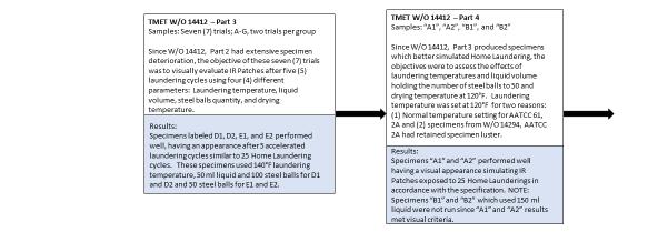
18 3.1.3 Test Procedures Six accelerated laundering trials were conducted by NSRDEC Textile Material Evaluation Team (TMET) to establish procedures for IR patches (see Appendix D). This was done in order to determine correlation between the accelerated laundering method with home laundering surface characteristics and visual appearance test specimen baselines. The trials ranged from laundering test specimens using the same test conditions outlined in Table I of AATCC Test Method to formulating test procedures, which adjusted such factors as laundering temperature, liquid volume, and number of steel balls (which provide mechanical agitation). Each succeeding trial based its test procedures on results from the previous set of trials. For this study, surface/visual examinations were made prior to laundering (the initial state) and after each accelerated cycle. As outlined in AATCC Test Method , paragraph 2.1, each accelerated laundering cycle approximates five hand or home laundering cycles TMET Work Order Number The first trial, TMET Work Order Number 14294, was conducted to understand the effects of surface characteristics and visual appearance on test specimens using AATCC Test Method , Test Numbers 1A, 2A, and 3A procedures. See Table 4 for more details. These test numbers were selected because they represent typical laundering procedures for military end items. Specifically, 1A uses warm water with the lowest number of steel balls; 2A uses hot water, a medium number of steel balls, and is used to test Army Combat Shirts; and 3A uses extra hot water, the highest number of steel balls, and is used to test colorfastness of 50/50 nylon/cotton blend, wind resistant poplin rip stop cloth, which is the base material for the ACU. The full test condition table from AATCC Test Method can be found in Appendix E. Test number Base cloth test component size (inches) Table 4. Accelerated laundering TMET Work Order Number Laundering temperature ( F ± 4) Laundering cycles 1 Liquid volume (ml) Test canister size (ml) 1A 2 x (Type 1) 2A 2 x (Type 2) 3A 2 x (Type 2) Note: Four accelerated laundering cycles simulates 20 home laundering cycles TMET Work Order Number 14412, Part 1 Number of steel balls Oven drying temperature ( F) TMET Work Order Number was established to better track test procedure changes. Part I evaluated one laundering temperature against a variable number of steel balls in order to assess agitation on test specimens. The laundering temperature was set at 140 F to correlate with home laundering of ACUs under test conditions. The number of steel balls varied from a high of 100 to a low of 10. All trials used a 2-inch by 6-inch base cloth test component and were laundered for five accelerated cycles, which simulates 25 home laundering cycles. The test procedures are outlined in Table 5. 10
19 Test number Table 5. Accelerated laundering TMET Work Order Number 14412, Part 1 Laundering temperature ( F ± 4) Test canister size (ml) Liquid volume (ml) Number of steel balls Oven drying temperature ( F) A (Type 2) A (Type 2) A (Type 2) A (Type 2) TMET Work Order Number 14412, Part 2 TMET Work Order Number 14412, Part 2 enabled the evaluation of the laundering of 15 specimens that had been measured for Coefficient of Retroreflection (R A) prior to laundering. All trials used a 2-inch by 6-inch base cloth test component and were laundered for 5 accelerated cycles, which simulates 25 home laundering cycles. The test procedures are outlined in Table 6. Specimen Test numbers 1 Table 6. Accelerated laundering TMET Work Order Number 14412, Part 2 Laundering temperature ( F ± 4) Test canister size (ml) Liquid volume (ml) Number of steel balls Oven drying temperature ( F) (Type 2) Note: The test number was marked on the base cloth test component for tracking purposes and prevention of test specimen damage TMET Work Order Number 14412, Part 3 TMET Work Order Number 14412, Part 3 trials were conducted to evaluate four different test parameters: laundering temperature, liquid volume, number of steel balls, and drying temperature. All trials used a 2-inch by 6-inch base cloth test component and were laundered for 5 accelerated cycles, which simulates 25 home laundering cycles. The test procedures are outlined in Table 7. The TMET ID alpha character represents a set of test parameters while the numeric character represents the specimen; two test specimens were laundered for each set of parameters. TMET ID 1 Table 7. Accelerated laundering TMET Work Order Number 14412, Part 3 Laundering temperature ( F ± 4) Test canister size (ml) Liquid volume (ml) Number of steel balls Oven drying temperature ( F) A1 and A (Type 2) B1 and B (Type 2) C1 and C (Type 2) D1 and D (Type 2) E1 and E (Type 2) F1 and F (Type 2) G1 and G (Type 2) Note 1: For each test parameter, two test specimens were laundered; they were numbered 1 and 2 Note 2: The test parameters were the same as for AATCC Test Method except the oven temperature was set to 120 F 11
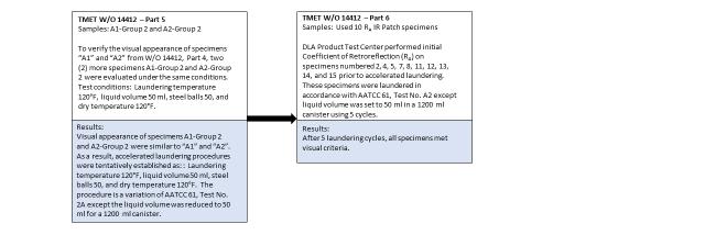
20 TMET Work Order Number 14412, Part 4 TMET Work Order Number 14412, Part 4 trials were conducted to assess the effect of liquid volume. All trials used a 2-inch by 6-inch base cloth test component and were laundered for 5 accelerated cycles, which simulates 25 home laundering cycles. The test procedures are outlined in Table 8. TMET ID 1 Table 8. Accelerated laundering TMET Work Order Number 14412, Part 4 Laundering temperature ( F ± 4) Test canister size (ml) Liquid volume (ml) Number of steel balls Oven drying temperature ( F) A1 and A (Type 2) B1 and B (Type 2) Note: For each test parameter, two test specimens were laundered; they were numbered 1 and TMET Work Order Number 14412, Part 5 TMET Work Order Number 14412, Part 5 trials were conducted to verify the effects of liquid volume reduction to 50 ml. All trials used a 2-inch by 6-inch base cloth test component and were laundered for 5 accelerated cycles, which simulates 25 home laundering cycles. The test procedures are outlined in Table 9. TMET ID 1 A1-Group 2 and A2-Group 2 Table 9. Accelerated laundering TMET Work Order Number 14412, Part 5 Laundering temperature ( F ± 4) Test canister size (ml) Liquid volume (ml) Number of steel balls Oven drying temperature ( F) (Type 2) Note: For each test parameter, two test specimens were laundered; they were numbered 1 and TMET Work Order Number 14412, Part 6 TMET Work Order Number 14412, Part 6 evaluated the laundering of 10 specimens that had been tested for R A prior to laundering. All trials used a 2-inch by 6-inch base cloth test component and were laundered for 5 accelerated cycles, which simulates 25 home laundering cycles. The test procedures are outlined in Table 10. Specimen Test numbers 1 2, 4, 5, 7, 8, 11, 12, 13, 14, and 15 Table 10. Accelerated laundering TMET Work Order Number 14412, Part 6 Laundering temperature ( F ± 4) Test canister size (ml) Liquid volume (ml) Number of steel balls Oven drying temperature ( F) (Type 2) Note: The test number was marked on the base cloth test component for tracking purposes and prevention of test specimen damage 12
.")
21 3.2 Results and Discussion After each accelerated laundering trial, the test specimens were examined for surface characteristics and visual appearance (shown previously in Table 2) plus visually compared to specimens laundered 25 times under home laundering conditions (see Section 2.2). The results from each accelerated laundering trial determined if changes were required of subsequent trials in order to correlate with home laundering results TMET Work Order Number The first accelerated laundering trial, which evaluated test specimens in accordance with the specifications given in Section , produced specimens having three distinctive appearances (see Figure 7). Laundered test specimens from Test Number 1A yielded a gently laundered product that had almost no changes from unlaundered test specimens. Test Number 2A specimens had similar surface characteristics/visual appearance approaching that of home laundered test specimens. Test Number 3A produced harshly laundered test specimens in which the black infrared translucent ink and top coating layers delaminated from the base material, a micro-prismatic retroreflective layer. Although Test Number 2A specimens demonstrated performance capabilities within the surface/visual parameters for home laundering, the laundering temperature was 20 F less than what is normally used to launder combat uniforms during testing. As a result, additional trials were needed to access test specimen performance when laundered at higher temperatures. a) b) c) Figure 7. TMET Work Order Number 14294, laundered test specimens after four cycles in accordance with AATCC a) Test 1A; b) Test 2A; c) Test 3A TMET Work Order Number 14412, Part 1 This trial held the laundering temperature at 140 F and varied the number of steel balls (see Section for test procedures). Because the IR patch is affixed to military garments, such as the ACU coat, all components (i.e., coat and patch) must be treated as a system during laundering. As a result, additional accelerated laundering trials were warranted to determine the effects in raising the laundering temperature from 120 F used in AATCC Test Method , Test Number 2A to 140 F used for laboratory testing of ACUs. Besides increasing the laundering temperature, mechanical agitation was also assessed to determine if the scrubbing action from steel balls affected the test specimens in the same manner or to a greater extent when the laundering temperature was increased. The trial was constructed with 4 test groups, each containing a different number of steel balls: 100, 50, 15, and 10. Laundering commenced with Test Number A , which used test parameters of 140 F with 100 steel balls. This test produced satisfactory results after each accelerated laundering cycle in which the specimens acquired comparable surface characteristics and visual appearance as those observed in 25 home laundering cycles (see Figures 5 and 8). Because the results of Test Number A closely paralleled home laundering outcomes, no further test groups from this trial were evaluated. 13
 one cycle; b) two cycles; c) three cycles; d) four cycles; e) five cycles 3.2.")
 measure the coefficient of retroreflection (R A) prior to laundering to quantify retroreflective performance (coefficient of retroreflection measurements")
; and 3) measure R A after laundering to assess retroreflective retention (DLA-PTC). The retroreflective test. Were performed in accordance with paragraphs 4.6.1 and 4.6.3 of CO/PD-06-05A.")

22 a) b) c) d) e) Figure 8. TMET Work Order Number 14412, Part 1, test specimens after accelerated laundering cycles. a) one cycle; b) two cycles; c) three cycles; d) four cycles; e) five cycles TMET Work Order Number 14412, Part 2 TMET Work Order Number 14412, Part 2 evaluated the laundering of 15 test specimens, numbered 16 to 30, in accordance with the specifications given in Section The three trial objectives were: 1) measure the coefficient of retroreflection (R A) prior to laundering to quantify retroreflective performance (coefficient of retroreflection measurements were done at the Defense Logistics Agency- Product Test Center (DLA-PTC)); 2) observe test specimen surface characteristics and visual appearance during the five accelerated laundering cycles (NSRDEC TMET); and 3) measure R A after laundering to assess retroreflective retention (DLA-PTC). The retroreflective test. Were performed in accordance with paragraphs and of CO/PD-06-05A. This non-destructive test does not affect test specimen surface characteristics or visual appearance. Because the main objective for this study was to develop an accelerated laundering test method, the R A measurements were only taken to follow specification requirements stated in paragraph of CO/PD-06-05A. Observations after the first laundering cycle noted slightly more variation in surface characteristics and visual appearance than what had been detected during TMET Work Order Number 14412, Part 1. By the third laundering cycle, test specimens exhibited surface characteristics and visual appearances that were normally seen after five accelerated laundering cycles (see Figures 9a-9c). A few test specimens had the black infrared translucent ink and top coating layers delaminated from the base material along the edges up to the stitching line. As laundering progressed through the fourth and fifth cycles, several test specimens exhibited catastrophic deterioration with up to 50% exposure of the base material (see Figures 9d-9i). Due to the number of unacceptable test specimens after five laundering cycles, the third trial objective, measure R A after laundering, was cancelled. 14
 three cycles, Specimen #21; b) three cycles, Specimen #22; c) three cycles, Specimen #24; d) four cycles, Specimen #26; e) four cycles, Specimen #28, f) four cycles, Specimen #30; g) five cycles,")

 examine key test")


23 a) b) c) d) e) f) g) h) i) Figure 9. TMET Work Order Number 14412, Part 2, test specimens after three, four, and five accelerated laundering cycles. A) three cycles, Specimen #21; b) three cycles, Specimen #22; c) three cycles, Specimen #24; d) four cycles, Specimen #26; e) four cycles, Specimen #28, f) four cycles, Specimen #30; g) five cycles, Specimen #26; five cycles, Specimen #28; i) five cycles, Specimen # TMET Work Order Number 14412, Part 3 Due to extensive specimen deterioration observed in TMET Work Order Number 14412, Part 2, the two objectives for this trial were as follows: 1) examine key test parameters to better understand the laundering interactions; and 2) achieve specimens that meet home laundering surface characteristics and visual appearance. Seven laundering trials were conducted in accordance with the specifications given in Section using four different test parameters: laundering temperature (120 F or 140 F), liquid volume (50 ml or 150 ml), number of steel balls (50 or 100), and oven drying temperature (120 F or 140 F). Although the liquid volume was set to either 50 ml or 150 ml, the test canister size was held at a constant of 1200 ml to allow the maximum frictional effect of the test specimen against the canister walls. After one laundering cycle, test specimens in TMET ID groups A through C had the black infrared translucent ink and top coating layers delaminated from the base material along the edges up to the stitching line; groups D thru G maintained test specimen integrity with respect to surface characteristics and visual appearance. Observations after the second laundering cycles noted that test specimens in TMET ID groups A thru C continued to deteriorate to the point some specimens were removed from the trials due to excessive exposure of the base material. Test specimens in groups D, E, and F maintained performance, while test specimens in group G had peeling of the black infrared translucent ink and top coating layers from the base material on one or more corners or on the edges up to the stitching line. After the third laundering cycle, test specimen performance fell into one of three categories: continued deterioration, groups A thru C (see Figure 10); maintained integrity, groups D and E (see Figure 11); and 15


 Group A specimen after three accelerated laundering cycles; b) Group B specimen")
 b) c) d) Figure 11.")

 Specimen E1 after three accelerated laundering")

 Specimen F1 after three accelerated laundering cycles; b) Specimen F2 after three")
24 minor edge peel with loss of surface luster, groups F and G (see Figure 12). The same performance categories were observed after laundering cycles 4 and 5 with degradation of the test specimens continuing at a minor rate. a) b) c) Figure 10. TMET Work Order Number 14412, Part 3, test specimen deterioration, three accelerated laundering cycles of Groups A, B, and C. a) Group A specimen after three accelerated laundering cycles; b) Group B specimen after three accelerated laundering cycles; c) Group C specimen after three accelerated laundering cycles a) b) c) d) Figure 11. TMET Work Order 14412, Part 3, test specimens maintained integrity, three accelerated laundering cycles of Groups D and E. a) Specimen D1 after three accelerated laundering cycles; b) Specimen D2 after three accelerated laundering cycles; c) Specimen E1 after three accelerated laundering cycles; d) Specimen E2 after three accelerated laundering cycles a) b) c) d) Figure 12. TMET Work Order Number 14412, Part 3, test specimens peeling to stitch line and loss of surface luster, three accelerated laundering cycles of Groups F and G. a) Specimen F1 after three accelerated laundering cycles; b) Specimen F2 after three accelerated laundering cycles; c) Specimen G1 after three accelerated laundering cycles; d) Specimen G2 after three accelerated laundering cycles 16
25 Close examination of specimens from TMET ID groups D, E, F, and G disclosed that only three test parameters were varied: laundering temperature (120 F or 140 F), liquid volume (50 ml or 150 ml), and number of steel balls (50 or 100). Test specimens in groups D and E were laundered at the higher temperature (140 F), maintained a constant liquid volume of 50 ml, and varied the number of steel balls by either 50 or 100. In contrast, specimens in groups F and G used the lower laundering temperature (120 F), retained a higher liquid volume (150 ml), and varied the number of steel balls by either 100 or 50. The core test parameters separating groups D and E from F and G were laundering temperature and liquid volume. At the higher laundering temperature and lower liquid volume, the test specimens maintained the initial surface luster, which was also observed on 25 cycle home laundered test specimens. In comparison, at the lower laundering temperature and higher liquid volume, the test specimen surface became dull with a matte haze. Through examination of test parameters, the liquid volume affected test specimen surface performance. The higher liquid volume created more agitation on the test specimen, thus forming surface modulations from low luster/matte hazing to a sanded surface TMET Work Order Number 14412, Part 4 The main objective for this accelerated laundering trial was to evaluate the effects of liquid volume on the test specimen. This trial set liquid volume level at 50 ml for test specimens A1 and A2 and 150 ml for test specimens B1 and B2. In addition to establishing the liquid volume test parameter, this trial also evaluated laundering temperature and number of steel balls. The laundering temperature was set back to 120 F for three reasons: 1) it is the normal temperature setting for AATCC Test Method , test number 2A; 2) independent and government laboratories are accustomed to this temperature setting and will not require equipment adjustment; and 3) Test Number 2A specimens from TMET Work Order Number retained the low gloss luster at this laundering temperature setting. Because variation in the number of steel balls had minimal to no effect on the previous test specimen outcomes, the steel ball quantity was set at 50 to correspond with AATCC Test Method , Test Number 2A. Specimens A1 and A2 performed well throughout the 5 accelerated laundering cycles to achieve surface characteristics and visual appearance proficiencies similar to 25 cycle home laundering test specimens (see Figure 13). Because A1 and A2 met the criteria using 50 ml liquid volume, specimens B1 and B2 were not evaluated. 17
 one cycle, specimen A1 ; b) one cycle, specimen A2 ; c) three cycles, specimen A1 ; d) three cycles, specimen A2 ; e) five cycles, specimen A1 ; f)")


 and accelerated laundering TMET Work Order Number 14412, Part 4 test")

26 a) b) c) d) e) f) Figure 13. TMET Work Order Number 14412, Part 4, test specimens after one, three, and five accelerated laundering cycles. a) one cycle, specimen A1 ; b) one cycle, specimen A2 ; c) three cycles, specimen A1 ; d) three cycles, specimen A2 ; e) five cycles, specimen A1 ; f) five cycles, specimen A TMET Work Order Number 14412, Part 5 TMET Work Order Number 14412, Part 5 was conducted to verify that a 50 ml liquid volume for accelerated laundering achieved similar surface characteristics and visual appearance as those observed on 25 cycle home laundered test specimens. This trial was performed in accordance with the specifications given in Section The trial produced surface characteristics and visual appearance for test specimens in A1-Group 2 and A2-Group 2. See Figures 14a and 14b, which are similar to both home laundering (see Figure 5) and accelerated laundering TMET Work Order Number 14412, Part 4 test specimens A1 and A2 (see Figures 13e and 13f). The test parameters for this Work Order were similar to AATCC Test Method , Table I, Test Number 2A procedures except the total liquid volume was set at 50 ml instead of 150 ml. Figure 14. TMET Work Order Number 14412, Part 5, test specimens after five accelerated laundering cycles. a) specimen A1-Group 2 ; b) Specimen A2-Group 2 When the test specimen preparation requirements (Section 3.1.2) are combined with the Table 11 test procedures, accelerated laundering procedures are defined for IR patches. 18
 Test Specimen location, upper third Test canister size (ml) Laundering temperature ( F ± 4) Liquid")
27 Table 11. Accelerated laundering: final procedures for IR patches Base cloth test component size (inches) Test Specimen location, upper third Test canister size (ml) Laundering temperature ( F ± 4) Liquid volume (ml) Percent powder detergent of total volume Number of steel balls Number of laundering cycles Oven drying temperature ( F) 2 x (Type 2) TMET Work Order Number 14412, Part 6 TMET Work Order Number 14412, Part 6, laundered 10 specimens numbered 2, 4, 5, 7, 8, 11, 12, 13, 14, and 15 in accordance with the specifications given in Section , which were the same procedures outlined in Table 11. These specimens had been tested for R A prior to laundering. The surface characteristics and visual appearance for these test specimens were similar to both TMET Work Orders 14412, Part 4 and Part 5 and home laundering Section 2.2 (see Figure 15). Figure 15. TMET Work Order Number 14412, Part 6, specimens after five accelerated laundering cycles. Top row, left to right: specimens 2, 4, 5, 7, and 8; bottom row, left to right: specimens 11, 12, 13, 14, and 15 19
 developed accelerated laundering test procedures for IR patches.")
28 4.0 Conclusions and Recommendations This study performed two tasks, as follows: (1) established a physical specimen baseline for surface characteristic and visual appearance of IR patches after exposure to 25 cycles of home laundering; and (2) developed accelerated laundering test procedures for IR patches. Home laundering was conducted in accordance with CO/PD-06-05A, which used AATCC Test Method 150 and produced test specimens with surface characteristics and visual appearance listed in Table 3 and diagramed in Appendix C. These test specimens exhibited tolerances with respect to base material exposure, creasing/bending without surface breakage, and edge curling in contrast to absolute surface/visual performance requirements stated in the purchase description. The resulting test specimen performance in the areas of surface characteristics and visual appearance established a baseline for 25 cycles of home laundered IR patches. Once the study established a home laundering baseline for analysis of test specimens, trials were executed in accordance with AATCC Test Method , or variations of it, to develop a five cycle accelerated laundering procedure for IR patches in order to reduce laundering time by approximately 80% and lower laundering cost nearly 75%. Test specimen preparation requirements (Section 3.1.2, and Table 11 under TMET Work Order Number 14412, Part 5) established accelerated laundering procedures that produced test specimens which had surface characteristics and visual appearance similar to the home laundering baseline. The accelerated laundering procedures for IR patches can be defined by three modifications of AATCC Test Method , which includes an elimination of some specimen preparation procedures, reduction of liquid volume from 150 ml to 50 ml, and a decrease in the maximum oven drying temperature from 160 F to 120 F. These recommended parameters, as also outlined in Table 11, were validated by several other entities. Base cloth swatches with the sewn-on test specimens that were provided to Precision Testing Laboratories, the Navy Clothing and Textile Research Facility (NCTRF) and the Defense Logistics Agency Product Test Center (DLA-PTC). These three entities laundered the samples according to AATCC Test Method , Table I, Test Number 2A procedures except the total liquid volume was set at 50 ml instead of 150 ml (Table 11) and visual examination of the samples matched the samples from the TMET laundering tests. When approval is granted from Product Manager Soldier, Clothing and Individual Equipment (PdM SCIE), IR patch end-item developer and Defense Logistics Agency, Troop Support, specification manager, technical data changes are recommended for CO/PD-06-05A to incorporate accelerated laundering procedures described in Table 11 and detailed in Appendix F. 17/015 20
29 Appendix A Home Laundering Laundering Procedures from Purchase Description, Patch and Brassard, Identification, Infrared Retroreflective, CO/PD-06-05A, dated 10 November 2011: After launderability (Type I only). Measure the initial coefficient of retroreflection on five (5) test specimens at the perpendicular orientation as specified in The laundered specimens shall be prepared in accordance with and laundered in accordance with After laundering, remeasure the coefficient of retroreflection for each of the test specimens. If any test specimen fails to retain a minimum of 50 percent of its initial coefficient of retroreflection requirements for home laundering, the sample unit shall be considered a failure Laundry specimen preparation (Type I only). Five (5) Type I specimens shall be stitched to a cloth prior to laundering Cloth and stitching requirements are listed in Table VII. TABLE VII. Laundry specimen preparation requirements. CHARACTERISTIC REQUIREMENT Cloth, weight, oz/sq. yd (min) 6.0 Cloth, dimensions, sq. inches Approximately 2160 Specimen placement Randomly placed on cloth with a 3-inch minimum from edge Stitching Box stitch, 8 (± 1) stitches per inch, standard 301 lockstitch, seam type SSau Laundering (Type I only). Type I specimens shall be laundered 25 cycles in accordance with AATCC Test Method 150 using AATCC 1993 Standard Reference Detergent WOB (without optical brightener). Wash, permanent press cycle, 140 F and rinse 80 F, 10 minutes agitation time using 66 grams AATCC detergent without bleach, dry permanent cycle for minutes Sewability (Type I only). The basic material shall be capable of being sewn per ASTM D 6193 with a standard lockstitch 301 per seam type SSau-4 (boxstitch). 21
30 This page intentionally left blank 22
31 Appendix B Home Laundering Observations Table B-1. Infrared Tools Test Specimens Laundering Cycle Observation Photo Number 0x, Initial Observed specimen sewn on cloth, MIL-DTL , Class 8 (ACU Universal Camouflage). Specimens sewn in accordance with IR patch specification 1x No change in appearance 2x Specimen #5, slight bend upwards on one corner 3x Specimens 4 and 5, slight fold upwards on one 4x corner Specimens 4 and 5, slight fold upwards on one corner 5x Specimen #1, slight fold upwards on two (2) corners; one corner less than 0.03-inch infrared top coating lifting from base. 8x 10x 12x 15x 20x Same as 5x laundering observations Specimens #3, 4, and 5 lifting on corner; little more bending on corners. Specimens #1, 3, 4, and 5 little more bending on corners up to 0.10-inch, very light creasing Little more bending on corners, very light creasing, film lifting at corners. Specimen #1 lifting of film along a straight edge. Specimens #1-5, bending on corners, very light creasing, film lifting at corners and on few straight edges, no more than 0.03-inches film lifting on edge, 1659-film lifting on corner 1696-slight creasing 25x Same as 20x with a little heavier creasing 1741-film lifting at corner, 1742-creasing, and film lifting along edge 23
32 Table B-2. CeJay Engineering Test Specimens Laundering Cycle Observation Photo Number Observed CeJay test specimens sewn on cloth 1788, #5 panel for any markings or stitching concerns in order to establish reference point. Some test specimens were stitched with uneven tension 0x, Initial on the bobbin (lower) thread which allowed the upper thread to be seen as a straight line on the specimen surface. The tension did not affect the test specimens which were securely attached to the cloth panel. All test specimens laid flat on the cloth panel. 1x Some test specimens exhibited on the corners a 1803, #3 slight lifting upwards (curling) from the cloth panel. 2x Continued to observe test specimen corners 1826 slightly lifting upwards from cloth panel. 3x Specimen #1 on upper corner had black top 1842, 1844 coating peeling back from base material. Continue to observe all test specimens having some corners slightly lifting upwards from the cloth panel. 4x Same observation as 3x. 1871, 1872, x Specimen #1 corners on the upper left and 1895 lower right had the black top coating peeling back from the base material. Continue to observe all test specimens having some corners slightly lifting upwards from the cloth panel. 8x Specimen #1 corners on the upper left and lower right had the black top coating peeling back from the base material were still intact. 10x Specimen #1 showed more curling from the cloth panel, especially the upper left and lower right corners. Peeled corner were still intact. 12x Same observation as 10x. 15x Same observation as 12x. 20x 25x Specimen #1 showed more curling from the cloth panel, especially the upper left and lower right corners. Peeled corner were still intact. Approximately 0.01-inch shrinkage of black top coating receding from all edges. Specimen #2 had black top coating peeling from lower edge. Specimen #2 had a little more shrinkage of black top coating from edges. 2054, 2055,
33 Table B-3. Infrared Tools Coefficient of Retroreflection (R A) Test Specimens Laundering Cycle Observation Photo Number 0x, Initial Prior to sewing on the test specimen, DLA-Product Test Center evaluated IR patches for initial Coefficient of Retroreflection (R A). Each test specimen was assigned a number to track R A after laundering. This evaluation randomly selected specimens numbered 1, 3, 6, 9, and 10. All specimens laid flat on cloth panel after stitching. Test specimens # 1 and 10 had a very light imprinted vertical lines within the black top coating Specimen #1 had small needle size dent. 1x Specimens remained flat. Specimen #9, slight crease on upper right side Vertical lines could still be seen on specimens 1 and 10. 5x Specimens # 1, 6, and 9 had two (2) corners slightly raised from cloth panel Specimens #1 and 6 had some soft creases on the center surface Specimen #10, lower left corner black top coating peeled away exposing approximately 0.03-inches of base material. 15x Specimen #3 within the box stitched area had soft creases. Also light curling of lower left and right corners. Specimen #9 had the black top coating peel from the base material along the left edge and upper left corner Specimen #6 curling on three (3) corners plus light creasing. 25x Observations similar to 15x, except specimen curling was slightly greater Creases still present but slightly more pronounced Curling on corners Black top coating peeling on some corners and along some edges. 2293, 2294 (vertical imprinted lines) and 2289-needle size dent , , 2355, 2360, 2362, 2368,
34 This page intentionally left blank 26
35 Appendix C Home Laundering Surface Characteristics Baseline 27
36 This page intentionally left blank 28

37 Appendix D IR Patch Accelerated Laundering Sequence 29
38 This page intentionally left blank 30
39 Appendix E Table I Test Conditions of AATCC Test Method
40 This page intentionally left blank 32

41 Appendix F Proposed Changes to AATCC Test Method 61 33
HALON FLIGHTLINE EXTINGUISHER EVALUATION: DATA SUPPORTING STANDARD DEVELOPMENT [INCLUDES NOVEMBER 2007 ADDENDUM]
![HALON FLIGHTLINE EXTINGUISHER EVALUATION: DATA SUPPORTING STANDARD DEVELOPMENT [INCLUDES NOVEMBER 2007 ADDENDUM]](/thumbs/77/74926656.jpg "HALON FLIGHTLINE EXTINGUISHER EVALUATION: DATA SUPPORTING STANDARD DEVELOPMENT [INCLUDES NOVEMBER 2007 ADDENDUM]") AFRL-RX-TY-TR-2008-4573 HALON FLIGHTLINE EXTINGUISHER EVALUATION: DATA SUPPORTING STANDARD DEVELOPMENT [INCLUDES NOVEMBER 2007 ADDENDUM] John R. Hawk Applied Research Associates P.O. Box 40128 Tyndall
AFRL-RX-TY-TR-2008-4573 HALON FLIGHTLINE EXTINGUISHER EVALUATION: DATA SUPPORTING STANDARD DEVELOPMENT [INCLUDES NOVEMBER 2007 ADDENDUM] John R. Hawk Applied Research Associates P.O. Box 40128 Tyndall
MINIMUM PERFORMANCE REQUIREMENT FOR AIR FORCE FLIGHTLINE FIRE EXTINGUISHERS:
 AFRL-ML-TY-TR-02-4540 MINIMUM PERFORMANCE REQUIREMENT FOR AIR FORCE FLIGHTLINE FIRE EXTINGUISHERS: EXTINGUISHING PERFORMANCE AGAINST 3-DIMENSIONAL AND HIDDEN FIRES MAY 2002 Approved for Public Release;
Converting Existing Copper Wire Firing System to a Fiber-Optically Controlled Firing System for Electromagnetic Pulsed Power Experiments
 ARL-TN-0863 DEC 2017 US Army Research Laboratory Converting Existing Copper Wire Firing System to a Fiber-Optically Controlled Firing System for Electromagnetic Pulsed Power Experiments by Robert Borys
Low Impact Development at Naval Facilities: Opportunities and Constraints
 Low Impact Development at Naval Facilities: Opportunities and Constraints Jim Harris, PE and Khoi Nguyen, PhD, PE Naval Facility Engineering Command Atlantic Sustainability Track 8027 - May 7, 2009 Environment,
The Conservation Fund The Center for Conservation and Development
 The Conservation Fund The Center for Conservation and Development Partners in Land and Water Conservation Smart Growth and Sustainable Ranges August 23, 2004 Savannah, GA The Conservation Fund--8/23/04
EXTINGUISHMENT AND BURNBACK TESTING OF FIRE FIGHTING AGENTS
 AFRL-ML-TY-TR-2005-4581 EXTINGUISHMENT AND BURNBACK TESTING OF FIRE FIGHTING AGENTS Kimberly D. Barrett Jennifer L. Kalberer Applied Research Associates, Inc. P.O. Box 40128 Tyndall AFB, FL 32403 Interim
Vision Protection From Lasers Overview for Dr. Beagley, Australia
 DISTRIBUTION A: Approved for public release; Distribution is Unlimited. Vision Protection From Lasers Overview for Dr. Beagley, Australia DISTRIBUTION STATEMENT A: Unlimited distribution. Approved for
A Novel Approach for a Hostile Arms Fire Sensor
 UNCLASSIFIED: Dist A. Approved for public release Joseph Rudy Montoya, PhD and Jorge Melchor US Army Research Laboratory-SLAD White Sands Missile Range, NM Venu Siddapureddy and Darryl Bryk US Army RDECOM-TARDEC
Direct measurement of the aerosol absorption and extinction cross section for a variety of chemical and biological simulants in the LWIR
 Direct measurement of the aerosol absorption and extinction cross section for a variety of chemical and biological simulants in the LWIR Kristan P. Gurton Rachid Dahmani David Ligon Army Research Laboratory,
DURIP: Fast Oscilloscope and Detectors for Air Laser Research
 DURIP: Fast Oscilloscope and Detectors for Air Laser Research Office of Naval Research N14-13-1-683 Principal Investigator Richard Miles Princeton University Department of Mechanical and Aerospace Engineering
FIRE PROTECTION FOR. Dist A. MILITARY GROUND VEHICLES. Steve McCormick US Army RDECOM-TARDEC.
 FIRE PROTECTION FOR MILITARY GROUND VEHICLES Steve McCormick US Army RDECOM-TARDEC (586) 753-2610 steven.j.mccormick@us.army.mil April 2009 UNCLAS: Approved for public release Report Documentation Page
REPORT DOCUMENTATION PAGE
 REPORT DOCUMENTATION PAGE Form Approved OMB No. 0704-0188 The public reporting burden for this collection of information is estimated to average 1 hour per response, including the time for reviewing instructions,
Unattended Radiation Sensor Systems for Remote Terrestrial Applications and Nuclear Nonproliferation
 Unattended Radiation Sensor Systems for Remote Terrestrial Applications and Nuclear Nonproliferation Lodewijk van den Berg, Alan E. Proctor, Ken R. Pohl, Alex Bolozdynya and Raymond DeVito Constellation
Force Protection Joint Experiment (FPJE) Battlefield Anti-Intrusion System (BAIS) Sensors Data Analysis and Filtering Metrics
 Battlefield Anti-Intrusion System (BAIS) Sensors Data Analysis and Filtering Metrics") Force Protection Joint Experiment (FPJE) Battlefield Anti-Intrusion System (BAIS) Sensors Data Analysis and Filtering Metrics C.M. Barngrover, R.T. Laird, T.A. Kramer, J.R. Cruickshanks, S.H. Cutler Space
Force Protection Joint Experiment (FPJE) Battlefield Anti-Intrusion System (BAIS) Sensors Data Analysis and Filtering Metrics C.M. Barngrover, R.T. Laird, T.A. Kramer, J.R. Cruickshanks, S.H. Cutler Space
Industrial Workshop Gettysburg, PA February 26, 2004
 Industrial Workshop Gettysburg, PA February 26, 2004 US Army Corps of Engineers ERDC-CERL Using Air-to-Air Energy Recovery for Industrial Process and Energy Optimization to Comply with 90.1 and Score with
ECBC SBIR/STTR Projects. ECBC SBIR/STTR MSCoE STRF Conference
 ECBC SBIR/STTR Projects ECBC SBIR/STTR MSCoE STRF Conference JAMES M. CRESS, JANET L. JENSEN, JAMES O. JENSEN OCTOBER 2012 Report Documentation Page Form Approved OMB No. 0704-0188 Public reporting burden
Assessing the Impact of Wash Water Temperature, Detergent Type and Laundering Platform on Basic Clothing Attributes. Abstract.
 Assessing the Impact of Wash Water Temperature, Detergent Type and Laundering Platform on Basic Clothing Attributes Elizabeth P. Easter, PhD; Cinnamon, Meredith & Baker, Erin; University of Kentucky, Lexington,
Durability of Water-Repellent Finishes to Accelerated Laundering
 University of Rhode Island DigitalCommons@URI Open Access Master's Theses 2015 Durability of Water-Repellent Finishes to Accelerated Laundering Jessica Rose Brooks University of Rhode Island, jbcrw25@gmail.com
Standard Test Method for Colorfastness and Transfer of Color in the Washing of Leather 1
 Designation: 00 Standard Test Method for Colorfastness and Transfer of Color in the Washing of Leather 1 This standard is issued under the fixed designation ; the number immediately following the designation
Design Considerations for Abrasive Blast Rooms & Recovery Systems
 Clemco Industries Corp. presents Design Considerations for Abrasive Blast Rooms & Recovery Systems by Bob Kerr Business Development Manager Report Documentation Page Form Approved OMB No. 0704-0188 Public
HANTAVIRUS PREVENTION: CLEANUP OF RODENT CONTAMINATION
 HANTAVIRUS PREVENTION: CLEANUP OF RODENT CONTAMINATION Technical Information Paper 18-001-0306 Hantaviruses in the Americas may cause human disease involving the lungs, hence the name "hantavirus pulmonary
INK CURING TIPS TIPS & TECHNIQUES
 INK CURING TIPS TIPS & TECHNIQUES THE INK CURING PROCESS AND BENEFITS OF LOW CURE INKS SCIENCE OF CURE There are typically three different types of cure equipment that are used in the textile screen printing
Recent Advances in Mercuric Iodide Detector Fabrication and Instrument Development*
 Recent Advances in Mercuric Iodide Detector Fabrication and Instrument Development* Lodewijk van den Berg and Steven W. Pauly Constellation Technology Corp., 7887 Bryan Dairy Road, Suite 100, Largo, FL
FIRE HAZARD ASSESSMENT IN SUPPORTING FIRE PROTECTION SYSTEM DESIGN OF A CHEMICAL PROCESS FACILITY ABSTRACT
 FIRE HAZARD ASSESSMENT IN SUPPORTING FIRE PROTECTION SYSTEM DESIGN OF A CHEMICAL PROCESS FACILITY Ali Pezeshk, Joseph Chang, Dwight Hunt, and Peter Jahn Parsons Infrastructure & Technology Group, Inc.
Modern Consumer Laundry Will Protecting the Environment Protect our Clothes? Vikki B. Martin Cotton Incorporated
 Modern Consumer Laundry Will Protecting the Environment Protect our Clothes? Vikki B. Martin Cotton Incorporated Use Phase of Cradle to Grave O Consumer use impact is due mainly to energy and water used
EVALUATION OF FIKE CORPORATION S EXPLOSION SUPPRESSION SYSTEM FOR ULTRA-HIGH SPEED FIRE SUPPRESSION APPLICATIONS
 AFRL-RX-TY-TR-2008-4516 EVALUATION OF FIKE CORPORATION S EXPLOSION SUPPRESSION SYSTEM FOR ULTRA-HIGH SPEED FIRE SUPPRESSION APPLICATIONS John Hawk, PE Applied Research Associates P.O. Box 40128 Tyndall
QUICKWASH PLUS. Accelerated Washing and Drying System
 QUICKWASH PLUS Accelerated Washing and Drying System Taking the Guesswork Out of Maximizing Fabric Yield Customers tend to expect their apparel purchases to retain the same fit and appearance throughout
PRODUCT PERFORMANCE TEST REPORT. Report No.: D Test Date: May 29, Rendered to: Natural Light Energy Systems Phoenix, Arizona
 Architectural Testing PRODUCT PERFORMANCE TEST REPORT Report No.: D7226.01-121-24 Test Date: May 29, 2014 Rendered to: Natural Light Energy Systems Phoenix, Arizona PRODUCT TYPE: Tubular Daylight Device
Sustainability Criteria for Planning, Constructing, and Operating Contingency Bases
 Sustainability Criteria for Planning, Constructing, and Operating Contingency Bases Giselle Rodriguez, P.E. Civil and Environmental Engineer Construction Engineering Research Laboratory Engineer Research
Polyester/cotton for pillow cases
 South Dakota State University Open PRAIRIE: Open Public Research Access Institutional Repository and Information Exchange Bulletins South Dakota State University Agricultural Experiment Station 1-1-1974
PERFORMANCE METRICS FOR SAFE LASER OPERATIONS AT SLAC NATIONAL ACCELERATOR LABORATORY 1 Paper # 203
 PERFORMANCE METRICS FOR SAFE LASER OPERATIONS AT SLAC NATIONAL ACCELERATOR LABORATORY 1 Paper # 203 SLAC-PUB-15356 January 2013 Michael Woods SLAC National Accelerator Laboratory, 2575 Sand Hill Rd., Menlo
ISO Textiles Domestic washing and drying procedures for textile testing
 INTERNATIONAL STANDARD ISO 6330 Third edition 2012-04-15 Textiles Domestic washing and drying procedures for textile testing Textiles Méthodes de lavage et de séchage domestiques en vue des essais des
DEMYSTIFYING FR CLAIMS: AN ERGODYNE WHITE PAPER
 DEMYSTIFYING FR CLAIMS: AN ERGODYNE WHITE PAPER Each year, hundreds of burn injuries and deaths are recorded from workers encountering open flame and high heat or exposure to flash fires and electrical
Fabric Soil-Removal Test Method
 1 O 5 Unbound issue 9 E 55 Does not circula. 0. 9 3 Special Report 983 February 1998 Fabric Soil-Removal Test Method 0 8 9 18 /// CkG) * L IBRAR Y OREGON STA N E 9?S? RA 1/ I u tversay- 2-16-)u\-L-1 Agricultural
PART I - MODELING DRYING OF THREE-DIMENSIONAL PULP MOLDED STRUCTURES - EXPERIMENTAL PROGRAM
 Drying '98 - Proceedings of the 11 th International Drying Symposium (IDS '98) Halkidiki, Greece, August 19-22, 1998, vol. A, pp. 349-356 PART I - MODELING DRYING OF THREE-DIMENSIONAL PULP MOLDED STRUCTURES
REPORT DOCUMENTATION PAGE
 REPORT DOCUMENTATION PAGE Form Approved OMB NO. 0704-0188 The public reporting burden for this collection of information is estimated to average 1 hour per response, including the time for reviewing instructions,
Drop-In Specifications INTEGRATED DRAINAGE SYSTEM GEOMEMBRANE
 Drop-In Specifications INTEGRATED DRAINAGE SYSTEM GEOMEMBRANE The following specification is a sample guideline to be customized by the engineer for preparing site specific specification. This information
NEW CD WARP CONTROL SYSTEM FOR THE CORRUGATING INDUSTRY
 NEW CD WARP CONTROL SYSTEM FOR THE CORRUGATING INDUSTRY USING A NEW CONCEPT IN MOISTURE SENSING AND CONTROL BY DRYING TECHNOLOGY, INC A New CD Warp Control System For the Corrugating Industry Introduction:
AFRL-RB-WP-TR
 AFRL-RB-WP-TR-2012-0191 NOVEL HEAT TRANSFER DEVICE RESEARCH Ryan E. Mikus Advanced Structural Concepts Branch Structures Division Kenneth D. Kihm University of Tennessee APRIL 2012 Interim Report See additional
REPORT NUMBER: SAT-001B ORIGINAL ISSUE DATE: February 29, 2016 REVISED DATE:
 Page 1 of 10 TEST REPORT REPORT NUMBER: 102317918SAT-001B ORIGINAL ISSUE DATE: February 29, 2016 REVISED DATE: EVALUATION CENTER Intertek Testing Services NA Inc. 16015 Shady Falls Road Elmendorf, TX 78112
Developing a Fire Test Strategy for Storage Protection Under Sloped Ceilings
 Developing a Fire Test Strategy for Storage Protection Under Sloped Ceilings Justin A. Geiman, Noah L. Ryder Fire & Risk Alliance, Rockville, MD, USA André W. Marshall Custom Spray Solutions, Silver Spring,
I N D U S T R I A L Y A R D S
 I N D U S T R I A L Y A R D S GEOTEXTILES INDUSTRIAL YARDS 1.0 Features of INDUSTRIAL PG 2 YARDS 2.0 How Typar geotextiles PG 2 work 4.0 Installation guide PG 7 5.0 Overlap and joining PG 8 6.0 Setting
UNIFIED FACILITIES GUIDE SPECIFICATIONS
 USACE / NAVFAC / AFCEC / NASA UFGS-28 20 02 (November 2008) ----------------------------- Preparing Activity: USACE Superseding UFGS-13729 (April 2006) UNIFIED FACILITIES GUIDE SPECIFICATIONS References
Technical Training International Textiles Training September 2018 Ellen Roaldi Instructor
 Technical Training International Textiles Training September 2018 Ellen Roaldi Instructor www.astm.org ASTM D1230 Flammability of Apparel Textiles Scope: This test method covers the evaluation of the flammability
THERMAL TEST REPORT SPRAY COOLING COMPARITIVE ANALYSIS. 21 June 2001
 THERMAL TEST REPORT SPRAY COOLING COMPARITIVE ANALYSIS 21 June 2001 Prepared by: Naval Surface Warfare Center Crane Division 300 Highway 361 Crane, Indiana 47522-5001 Goals The main objective of this project
PERFORMANCE TEST REPORT. Rendered to: Metal Building Manufacturers Association Cleveland, Ohio
 PERFORMANCE TEST REPORT Report No.: F6398.01-121-24 Test Date: March 9 th & 10th, 2016 Rendered to: Metal Building Manufacturers Association Cleveland, Ohio ASSEMBLIES: Metal Roof Panels and Clay Roof
AFRL-RX-TY-TR
 AFRL-RX-TY-TR-2012-0022 ANALYSIS OF COMMERCIALLY AVAILABLE HELMET AND BOOT OPTIONS FOR THE JOINT FIREFIGHTER INTEGRATED RESPONSE ENSEMBLE (JFIRE) Jennifer L. Schroeder President, Fire Science Solutions,
GEOMEMBRANE FIELD INSTALLATION
 GEOMEMBRANE FIELD INSTALLATION CONTENTS Introduction Quality Control and Quality Assurance Types of lining systems Basic Lining Design Executive Lining Design Basic Lining Design Specification Executive
Thick-Film Heater achieves Superior Performance in Thermal Response, Uniformity and Efficiency.
 Thick-Film Heater achieves Superior Performance in Thermal Response, Uniformity and Efficiency. by Mary Ruggiero, P.Eng., PhD and John Stockton, P.Eng Abstract IntegrAL thick-film heaters by Datec Corporation
ORALITE Microprismatic Garment Tapes
 Page 1 of 5 This document applies to ORALITE microprismatic tapes (garment trims) for sewing, heat sealing or welding to garments. Products included in this document are: ORALITE GP 100 Series ORALITE
Section Specification for Geotextile Used in Permanent Erosion Control Application
 Project Name: Project Number: 1 GENERAL Section 02370 Specification for Geotextile Used in Permanent Erosion Control Application 1.1 SECTION INCLUDES A. Geotextile to prevent soil loss resulting in excessive
ON THE BUTTON A reference guide to environmental ratings used for push button enclosures
 ON THE BUTTON A reference guide to environmental ratings used for push button enclosures A REFERENCE GUIDE TO KEY TOPICS IN PUSH BUTTON SELECTION AND SAFETY CONTENTS I. INTRODUCTION...............................
Distribution Restriction Statement
 DEPARTMENT OF THE ARMY U.S. Army Corps of Engineers CEMP-ET Washington, DC 20314-1000 ETL 1110-3-489 Technical Letter No. 1110-3-489 3 April 1998 Engineering and Design DOMESTIC WATER HEATERS FOR BARRACKS
Oral Syringe Product Stability &
 Oral Syringe Product Stability & Print Durability Comparison The Comar Oral Syringe dispenser design has proven to be the most stable product for ease of use and legibility when exposed to a series of
Australian Standard. Methods for fire tests on building materials, components and structures
 AS 1530.3 1989 Australian Standard Methods for fire tests on building materials, components and structures Part 3: Simultaneous determination of ignitability, flame propagation, heat release and smoke
Rutgers Environmental Health and Safety (REHS)
") Rutgers Environmental Health and Safety (REHS) Program Name: Laboratory Laser Safety Program Responsible Executive: Executive Director of REHS Adopted: February 20, 2001 Reviewed/Revised: July 10, 2018
Rutgers Environmental Health and Safety (REHS) Program Name: Laboratory Laser Safety Program Responsible Executive: Executive Director of REHS Adopted: February 20, 2001 Reviewed/Revised: July 10, 2018
Saying Mahalo to Solar Savings: A Billing Analysis of Solar Water Heaters in Hawaii
 Saying Mahalo to Solar Savings: A Billing Analysis of Solar Water Heaters in Hawaii Jenny Yaillen, Evergreen Economics Chris Ann Dickerson, CAD Consulting Wendy Takanish and John Cole, Hawaii Public Utilities
Room Temperature MWIR FPAs: Return of the Lead Salts?
 Approved for public release; distribution is unlimited. Room Temperature MWIR FPAs: Return of the Lead Salts? Steven Jost, John Kuppenheimer and Greg Dudoff Sanders, A Lockheed Martin Company, Nashua,
Softened Water Benefits Study: Energy Savings Detergent Savings. Independent studies demonstrate the link. Executive Summaries
 Executive Summaries Softened Water Benefits Study: Energy Savings Detergent Savings Independent studies demonstrate the link /MarketTheResearch/ Introduction The Energy Savings Study (aka The Battelle
 Evaluating How Laundering Effects the Coefficient of Friction Values of Reusable Friction Reducing Devices Made From Woven Nylon Fabric with a Silicone Coating MEDICAL DEVICE ANALYSIS WHITE PAPER WWW.WYEASTMEDICAL.COM
When Precision is not good enough
 When Precision is not good enough Andrew Kelley XACT PCB Ltd North Shields, UK Abstract As PCB designs become ever more complex with more sequential build up layers, tighter annular ring designs and broader
TESTS OF ADSIL COATING
 TESTS OF ADSIL COATING Test B - Long Term Test FSEC-CR-1259-01 July 11, 2001 Prepared for: Bob Suggs Florida Power & Light Company 9250 W. Flagler Street Miami, Florida 33174 Principal Investigator Dr.
Douglas Gray -Sales Director
 AFIP Brings Drying To The Fore Douglas Gray -Sales Director douglas.gray@natgraph.co.uk >4200 Installations >35 years leadership DSC Testing Deep Knowledge Experience Know - How AFIP Coating Brings Drying
UNIFIED FACILITIES GUIDE SPECIFICATIONS
 USACE / NAVFAC / AFCEC / NASA UFGS-21 21 03.00 10 February 2009) ---------------------------------- Preparing Activity: USACE Superseding UFGS-21 21 03.00 10 (April 2006) UNIFIED FACILITIES GUIDE SPECIFICATIONS
Flow Research, Inc. (781) Water Street (781) (fax) Dear Marketing Manager:
 Water Street (781) (fax) Dear Marketing Manager:") Flow Research, Inc. (781) 245-3200 27 Water Street (781) 224-7552 (fax) Wakefield, MA 01880 www.flowresearch.com Dear Marketing Manager: I am very pleased to let you know about our new study, The Market
Flow Research, Inc. (781) 245-3200 27 Water Street (781) 224-7552 (fax) Wakefield, MA 01880 www.flowresearch.com Dear Marketing Manager: I am very pleased to let you know about our new study, The Market
SECTION SECURITY TESTING AND COMMISSIONING
 SECTION 280800 - SECURITY TESTING AND COMMISSIONING PART 1 - GENERAL 1.1 WORK INCLUDES A. General Description: This specification section covers the provision of preliminary testing, acceptance testing,
IAFF DIVISION OF OCCUPATIONAL HEALTH, SAFETY AND MEDICINE
 IAFF DIVISION OF OCCUPATIONAL HEALTH, SAFETY AND MEDICINE Position on the U.S. Army Soldier & Biological Chemical Command s (SBCCOM), Withdrawn 3/30 Rule and the New Guide: The Risk Assessment of Using
DRAFT NFPA 805 TRANSITION PILOT PLANT OBSERVATION GUIDANCE
 Revision D January 14, 2005 DRAFT NFPA 805 TRANSITION PILOT PLANT OBSERVATION GUIDANCE I. INTRODUCTION The Commission s requirements for fire protection of nuclear power plants allow licensees to voluntarily
Conceptual Design of a Better Heat Pump Compressor for Northern Climates
 Purdue University Purdue e-pubs International Compressor Engineering Conference School of Mechanical Engineering 1976 Conceptual Design of a Better Heat Pump Compressor for Northern Climates D. Squarer
TECHNICAL BULLETIN Weston Parkway, Cary, North Carolina, Telephone (919)
") TECHNICAL BULLETIN 6399 Weston Parkway, Cary, North Carolina, 27513 Telephone (919) 678-2220 TRI 3013 WRINKLE-RESISTANT FINISHING OF COTTON FABRICS AND GARMENTS 2000 Cotton Incorporated. All rights reserved;
TECHNICAL BULLETIN 6399 Weston Parkway, Cary, North Carolina, 27513 Telephone (919) 678-2220 TRI 3013 WRINKLE-RESISTANT FINISHING OF COTTON FABRICS AND GARMENTS 2000 Cotton Incorporated. All rights reserved;
Heat Transfer Enhancement using Herringbone wavy & Smooth Wavy fin Heat Exchanger for Hydraulic Oil Cooling
 Enhancement using Herringbone wavy & Smooth Wavy fin Exchanger for Hydraulic Oil Cooling 1 Mr. Ketan C. Prasadi, 2 Prof. A.M. Patil 1 M.E. Student, P.V.P.I.T.,Budhagaon,Sangli AP-India 2 Associate Professor,
Victoria & Albert Museum, London Medieval & Renaissance Galleries: A Passive Approach to Humidity Control
 Victoria & Albert Museum, London Medieval & Renaissance Galleries: A Passive Approach to Humidity Control Andrew Lerpiniere Steve Walker Michael Bingham Associate Director Associate Director Engineer Arup
U.S. Fire Department Profile 2015
 U.S. Fire Department Profile 2015 April 2017 Hylton J.G. Haynes Gary P. Stein April 2017 National Fire Protection Association Abstract NFPA estimates there were approximately 1,160,450 firefighters in
BRITE II Characterization and Application to a New Advanced Flight Motion Simulator
 BRITE II Characterization and Application to a New Advanced Flight Motion Simulator D. Brett Beasley and Daniel A. Saylor Optical Sciences Corporation Huntsville, Alabama Jim Buford US Army Aviation &
CHAPTER I INTRODUCTION. In the modern life, electronic equipments have made their way
 1 CHAPTER I INTRODUCTION In the modern life, electronic equipments have made their way in to practically every part, which is from electronic gadgets to high power computers. Electronic components have
NB/ 0695/MFFS/P 17A Feb 18 REQUEST FOR INFORMATION (RFI) FOR SUPPLY AND INSTALLATION OF MAGAZINE FIRE FIGHTING SYSTEM
 FOR SUPPLY AND INSTALLATION OF MAGAZINE FIRE FIGHTING SYSTEM") Tele: +91-11-23793514 Fax: +91-11-23793514 Directorate of NBCD Integrated Headquarters of Ministry of Defence (Navy) 15, A - Block Hutments Dalhousie Road New Delhi 110011 NB/ 0695/MFFS/P 17A Feb 18 REQUEST
Tele: +91-11-23793514 Fax: +91-11-23793514 Directorate of NBCD Integrated Headquarters of Ministry of Defence (Navy) 15, A - Block Hutments Dalhousie Road New Delhi 110011 NB/ 0695/MFFS/P 17A Feb 18 REQUEST
Water Heating, Boiler, and Furnace Cost Study (RES 19)
") Water Heating, Boiler, and Furnace Cost Study (RES 19) Final Report Prepared for: The Electric and Gas Program Administrators of Massachusetts Part of the Residential Evaluation Program Area Submitted
Water Heating, Boiler, and Furnace Cost Study (RES 19) Final Report Prepared for: The Electric and Gas Program Administrators of Massachusetts Part of the Residential Evaluation Program Area Submitted
AUDITORY SYSTEMS LABORATORY HEARING PROTECTION DEVICE ATTENUATION TEST REPORT
 AUDITORY SYSTEMS LABORATORY HEARING PROTECTION DEVICE ATTENUATION TEST REPORT! AUDITORY SYSTEMS LABORATORY GRADO DEPT. OF INDUSTRIAL & SYSTEMS ENGINEERING Dr. John G. Casali, Professor and Director COLLEGE
UNITED STATES DEPARTMENT OF AGRICULTURE FOREST SERVICE SPECIFICATION FOR LED HEADLAMP, FIREFIGHTER
 Specification 5100-451 April 2012 UNITED STATES DEPARTMENT OF AGRICULTURE FOREST SERVICE SPECIFICATION FOR LED HEADLAMP, FIREFIGHTER Comments and suggestions related to this standard should be addressed
Sensor Grand Challenges: An NVESD Perspective
 Approved for public release; distribution is unlimited Sensor Grand Challenges: An NVESD Perspective James D. Howe U. S. Army NVESD 23 February 1999 Form SF298 Citation Data Report Date ("DD MON YYYY")
Distribution Restriction Statement
 DEPARTMENT OF THE ARMY ETL 1110-3-485 U.S. Army Corps of Engineers CEMP-ET Washington, D.C. 20314-1000 Technical Letter No. 1110-3-485 15 October 1997 Engineering and Design FIRE PROTECTION FOR HELICOPTER
We Identify and S.T.O.P. Your Noise Problems
 ASTM E-84 TESTING FOR MANUFACTURER, RENDERED TO: Acoustical Surfaces Inc. 123 Columbia Court North, Suite 201 Chaska, MN 55318 Noise S.T.O.P. Fabrisorb Acoustical Wall Panels TESTED: OCTOBER 3, 2002 October
POWER Selecting Shell Side Design Temperature for Feedwater Heaters
 Proceedings of the ASME 2014 Power Conference POWER2014 July 28-31, 2014, Baltimore, Maryland, USA Selecting Shell Side Design Temperature for Feedwater Heaters POWER2014-32275 Kellen J. Muldoon American
VDE-QT-PV001:2012/01
 1 VDE-QT-PV001:2012/01 VDE-QT-PV001:2012/01 Combined IEC 61215 ed.2, IEC 61730-1 ed. 1, IEC 61730-2 ed.2 plus VDE addendums 2 VDE-QT-PV001:2012/01 CONTENTS 1 Scope and object 5 2 Normative references 5
lighting control systems Division - Name - Date - Language 1
 lighting control systems Division - Name - Date - Language 1 Report Documentation Page Form Approved OMB No. 0704-0188 Public reporting burden for the collection of information is estimated to average
API MANUAL OF PETROLEUM MEASUREMENT STANDARDS
 API MANUAL OF PETROLEUM MEASUREMENT STANDARDS Chapter 22 Testing Protocols Section 1 General Guidelines for Developing Testing Protocols for Devices Used in the Measurement of Hydrocarbon Fluids Type Testing
b. Laser Mishap. Any unplanned or unexpected event causing material loss or damage or causing personnel injury from laser use.
 5. Definitions a. Laser. An acronym for light amplification by stimulated emission of radiation. Any device that can be made to produce or amplify electromagnetic radiation in the x-ray, ultraviolet, visible,
Water Heating, Boiler, and Furnace Cost Study (RES 19)
") Water Heating, Boiler, and Furnace Cost Study (RES 19) Final Report Prepared for: The Electric and Gas Program Administrators of Massachusetts Part of the Residential Evaluation Program Area Submitted
Water Heating, Boiler, and Furnace Cost Study (RES 19) Final Report Prepared for: The Electric and Gas Program Administrators of Massachusetts Part of the Residential Evaluation Program Area Submitted
Maluna Unhinged vs Yeti Tundra Thermal Performance Comparison January 2017
 Maluna Unhinged vs Yeti Tundra Thermal Performance Comparison January 2017 Abstract A Maluna Unhinged cooler was tested and measured for performance relative to a Yeti Tundra cooler. Three identical tests
Official Journal of the European Union. (Non-legislative acts) REGULATIONS
 REGULATIONS") 19.6.2015 L 154/1 II (Non-legislative acts) REGULATIONS COMMISSION DELEGATED REGULATION (EU) 2015/942 of 4 March 2015 amending Delegated Regulation (EU) No 529/2014 supplementing Regulation (EU) No 575/2013
19.6.2015 L 154/1 II (Non-legislative acts) REGULATIONS COMMISSION DELEGATED REGULATION (EU) 2015/942 of 4 March 2015 amending Delegated Regulation (EU) No 529/2014 supplementing Regulation (EU) No 575/2013
7.3 Design and Development Design and development planning Design and development inputs Design and development outputs 7.3.
 Rev. 1 03/05/2015 ANNEX A to the Yokogawa Corporation of America Quality Assurance Manual For Additional Requirements selectively applied to ATEX and IECEx certified products CONTENTS 1. Scope 2. Purpose
HOW TO SELECT AN INDIRECT THERMAL TECHNOLOGY FOR INDUSTRIAL MATERIALS PROCESSING
 white paper HOW TO SELECT AN INDIRECT THERMAL TECHNOLOGY FOR INDUSTRIAL MATERIALS PROCESSING Better Thermal Processing Results Begin with Selecting the Right Technology Authored by Rob Grady Director of
[Docket No. FAA ; Product Identifier 2017-NE-02-AD; Amendment ; AD ]
![[Docket No. FAA ; Product Identifier 2017-NE-02-AD; Amendment ; AD ]](/thumbs/84/90584561.jpg "[Docket No. FAA ; Product Identifier 2017-NE-02-AD; Amendment ; AD ]") [Federal Register Volume 82, Number 189 (Monday, October 2, 2017)] [Rules and Regulations] [Pages 45710-45712] From the Federal Register Online via the Government Publishing Office [www.gpo.gov] [FR Doc
[Federal Register Volume 82, Number 189 (Monday, October 2, 2017)] [Rules and Regulations] [Pages 45710-45712] From the Federal Register Online via the Government Publishing Office [www.gpo.gov] [FR Doc
[Docket No. FAA ; Directorate Identifier 2012-NM-176-AD] Airworthiness Directives; DASSAULT AVIATION Airplanes
![[Docket No. FAA ; Directorate Identifier 2012-NM-176-AD] Airworthiness Directives; DASSAULT AVIATION Airplanes](/thumbs/81/82608001.jpg "[Docket No. FAA ; Directorate Identifier 2012-NM-176-AD] Airworthiness Directives; DASSAULT AVIATION Airplanes") This document is scheduled to be published in the Federal Register on 05/21/2013 and available online at http://federalregister.gov/a/2013-12077, and on FDsys.gov [4910-13-P] DEPARTMENT OF TRANSPORTATION
This document is scheduled to be published in the Federal Register on 05/21/2013 and available online at http://federalregister.gov/a/2013-12077, and on FDsys.gov [4910-13-P] DEPARTMENT OF TRANSPORTATION
C-01 FIRE DECKS AND BULKHEADS
 Guideline No.: C-01(201510) C-01 FIRE DECKS AND BULKHEADS Issued date: October 20,2015 China Classification Society Foreword: This Guide is a part of CCS Rules, which contains technical requirements, inspection
III.DRAINAGE. This section describes the use of geotextiles in underdrains for two different field conditions:
 III.DRAINAGE This section describes the use of geotextiles in underdrains for two different field conditions: Protected (or light duty installations) and, Unprotected (for heavy duty installations). Both
SPECIALTY CROPS PROGRAM GROWER RESEARCH AND EDUCATION GRANT PROJECT REPORT
 SPECIALTY CROPS PROGRAM GROWER RESEARCH AND EDUCATION GRANT PROJECT REPORT PROJECT TITLE High tunnel strawberry production in suspended versus in-ground beds: can a suspended growing system be a profitable
The Economics of Drying.
 The Economics of Drying. How To Improve Bottom Line Profits in Processing Innovations for a better world. The Economics of Drying How To Improve Bottom Line Profits in Processing Drying is an energy intensive
Webinar November 12, 2014
 Webinar November 12, 2014 Dennis L. Mater dennis.l.mater@dupont.com FR Apparel Sales Technical Leader North America Webinar Overview Introduction Hazard Risk Types Contrast Short Duration Fire and Arc
MIL-STD-1407B 17 December 1985 SUPERSEDING MIL-STD-1407A 16 July 1975 MILITARY STANDARD HEATERS, VEHICULAR COMPARTMENT; HEATERS, COOLANT, ENGINE;
 17 December 1985 SUPERSEDING MIL-STD-1407A 16 July 1975 MILITARY STANDARD HEATERS, VEHICULAR COMPARTMENT; HEATERS, COOLANT, ENGINE; HEATERS, SPACE; HEATERS, DUCT-TYPE AMSC N/A FSC 4520 DISTRIBUTION STATEMENT