FlexLine Electrode Steam Humidifiers
|
|
|
- Daisy Sims
- 5 years ago
- Views:
Transcription


1 FlexLine Electrode Steam Humidifiers Manual ÁFLE.ENBÈ FLE.EN E
2 Certain computer programs contained in this product [or device] were developed by HygroMatik GmbH ("the Work(s)"). Copyright HygroMatik GmbH [ ] FLE 05/10/15/20/25/30/40/50/65/80/100/130 EN All Rights reserved. Current version of this manual can be found at: HygroMatik GmbH grants the legal user of this product [or device] the right to use the Work(s) solely within the scope of the legitimate operation of the product [or device]. No other right is granted under this licence. In particular and without prejudice to the generality of the foregoing, the Work(s) may not be used, sold, licensed, transferred, copied or reproduced in whole or in part or in any manner or form other than as expressly granted here without the prior written consent of HygroMatik GmbH. Information in this manual is subject to change or alteration without prior notice. Risk of electrical shock! Hazardous electrical high voltage! All electrical work to be performed by certified expert staff (electricians or expert personnel with eqivalent training) only. Page 2
3 1. Introduction Typographic Distinctions Documentation Symbols in Use Specific Symbols related to Safety Instructions General Symbols Intended Use Safety Instructions Guidelines for Safe Operation Scope Unit control Unit Operation Mounting, dismantling, maintenance and repair of the unit Electrical Disposal after dismantling Transport Overview Packing Interim Storage Check for Complete and Correct Delivery of Goods Functional Description and Device Composition Mode of Action Mechanical Construction Operating sequence Mechanical installation Environment Parameters to be met and Mounting Recommendations Dimensions and Mounting Directions Unit Installation Check Absorption Distance BN Determining the Absorption Distance Absorption Distance Nomogram Steam Manifold General installation guidelines Recommendations for dimensioning Steam line and condensate hose layout Guide lines for steam line design Condensate hose layout Steam line and condensate hose installation types Water connection Operation with softened water Water supply Water discharge Water connections final check Page 3
4 7. Electrical connection Electrical installation approach Cable connections Safety interlock Connection diagrams Electrical installation check list Commissioning Maintenance General Service messages Service messages for preventive maintenance Safety instructions for maintenance Maintenance frame work Removal and reinstallation of the steam cylinder Steam cylinder, electrodes and cylinder base cleaning Checking cable connections Solenoid valve removal/reinstallation and fine filter cleaning Cleaning of blow-down pump Inspection of hoses Electrode replacement Functional check Finishing maintenance Dismantling Declaration of Conformity Spare Parts Technical specifications Exploded view View of housing Page 4
5 1. Introduction Dear Customer, Thank you for choosing a HygroMatik steam humidifier. HygroMatik steam humidifiers represent the latest in humidification technology. In order to operate your HygroMatik steam humidifier safely, properly and efficiently, please read these operating instructions. Employ your steam humidifier only in sound condition and as directed. Consider potential hazards and safety issues and follow all the recommendations in these instructions. If you have additional questions, please contact your expert dealer. For all technical questions or spare parts orders, please be prepared to provide unit type and serial number (see name plate on the unit). 1.1 Typographic Distinctions Preceded by a bullet: general specifications» Preceded by an arrow: procedures for servicing or maintenance which should or must be performed in the indicated order Versions in Other Languages These operating instructions are available in several languages. If interested, please contact HygroMatik or your HygroMatik dealer. 1.3 Symbols in Use Specific Symbols related to Safety Instructions According to ANSI Z535.6 the following signal words are used within this document: DANGER indicates a hazardous situation which, if not avoided, will result in death or serious injury. WARNING indicates a hazardous situation which, if not avoided, could result in death or serious injury. CAUTION indicates a hazardous situation which, if not avoided, could result in minor or moderate injury. italics Installation step which must be checked off. Terms used with graphics or drawings NOTICE is used to address practices not related to physical injury General Symbols 1.2 Documentation Retention Please retain these operating instructions in a secure, always accessible location. If the product is resold, turn the documentation over to the new operator. If the documentation is lost, please contact HygroMatik. This symbol is used whenever a situation requires special attention beyond the scope of safety instructions. Page 5

6 1.4 Intended Use HygroMatik electrode steam humidifiers serve for steam production based on tap water or partially softened water. Only use supply water featuring a conductivity of 125 to 1250 µs/cm. Only qualified and authorised personnel may operate the unit. Persons transporting or working on the unit must have read and understood the respective parts of this manual, especially the Safety Instructions given in chapter 2. Additionally, operating personnel must be informed of any possible hazards. A copy of the manual is to be stored at the unit s operational location (or near the unit). By construction, HygroMatik steam humidifiers are not qualified for exterior application. D1: Lower threshold C1: Range of reduced conductivity (adjustment required) A: Normal Tap water B: Range of increased conductivity C2: Range of high conductivity (adjustment required) D2: Upper threshold Risk of scalding! Steam with a temperature of up to 100 C (212 F) is produced. Do not inhalate steam directly! In the C1 and C2 ranges, adaptation of the periodic blow-down frequency may be required. Pls. refer to the partial and full blowdown parameter descriptions given in the blow-down submenu chapter as well as in the glossary. Proper usage also comprises the adherence to the conditions specified by HygroMatik for: installation dismantling reassembly commissioning operation maintenance disposal Page 6
7 2. Safety Instructions These safety instructions are required by law. They promote workplace safety and accident prevention. 2.1 Guidelines for Safe Operation Scope Comply with the accident prevention regulation DGUV Regulation 3 to prevent injury to yourself and others. Beyond that, national regulations apply without restrictions Unit control Do not perform any work which compromises the safety of the unit. Obey all safety instructions and warnings present on the unit. In case of a malfunction or electrical power disruption, switch off the unit immediately and prevent a restart. Repair malfunctions promptly. Risk of material damage! The unit may be damaged if switched on repeatedly following a malfunction without prior repair. Rectify defects immediately! The unit must not be operated on a DC power supply. The unit may only be used connected to a steam pipe that safely transports the steam. Regularly check that all safety and monitoring devices are functioning normally. Do not remove or disable safety devices. Restricted use. IEC stipulates as follows: This device may be used by children of eight years of age and above as well as by persons with reduced physical, sensory or mental capabilities or lack of experience and knowledge so long as they are supervised or have been instructed regarding the safe use of the device and understand the hazards that may result from it. Cleaning and user maintenance of the unit must not be undertaken by children without supervision Unit Operation Risk of scalding! Uncontrolled hot steam escape in case of leaking or defective components possible. Switch off unit immediately. Page 7
8 2.1.4 Mounting, dismantling, maintenance and repair of the unit The HygroMatik steam humidifier is IP20 protected. Make sure that the unit is not object to dripping water in the mounting location. Installing a humidifier in a room without water discharge requires safety devices to protect against water leakages. Use only original fuses with the appropriate amperage rating. Regularly check the unit s electrical equipment. Promptly repair any damage such as loose connections or burned wiring. Responsibility for intrinsically safe installation of the HygroMatik steam humidifiers is incumbent on the installing specialist company. Use genuine spare parts only After any repair work, have qualified personnel check the safe operation of the unit Attaching or installing of additional components is permitted only with the written consent of the manufacturer 2.2 Disposal after dismantling The operator is responsible for the disposal of unit components as required by law Electrical Risk of electrical shock! Hazardous electrical voltage! Any work on the electrical system to be performed by certified expert staff (electricians or expert personnel with comparable training) only. Disconnect unit components from electrical power supply prior to work. After electrical installation or repair work, test all safety mechanisms (such as grounding resistance). Page 8
9 3. Transport 3.1 Overview Proceed carefully when transporting the steam humidifier in order to prevent damage due to stress or careless loading and unloading. Time limits for filing freight claims with shipping companies are*: Shipping company Carriers Parcel service After receipt of goods no later than 4 days immediately * Time limits for some services subject to change. 3.2 Packing Pay attention to the icons affixed to the packing box. 3.3 Interim Storage Store the unit in a dry place and protect from frost and strong sunlight. 3.4 Check for Complete and Correct Delivery of Goods Upon receipt of the unit, confirm that: model and serial number on the name plate match those specified in the order and delivery documents the equipment is complete and all parts are in perfect condition In case of damage from shipment and/or missing parts, immediately notify the carrier or supplier in writing. Page 9

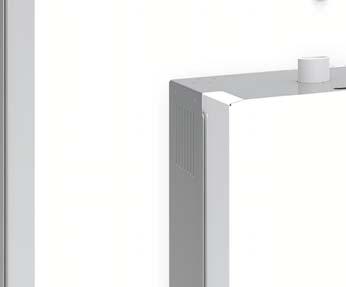
10 4. Functional Description and Device Composition 4.1 Mode of Action Making use of the frictional heat caused by current flow in a water tank The HygroMatik humidifier utilizes the conductivity normally present in tap water for steam production. Electrodes inside an enclosed steam cylinder are immersed directly into the tap water. They are connected to the alternating current. The conductivity of the water generates an electric current between the electrodes. In this way, the electric power supplied is converted directly into heat without energy loss. Steam exit The steam produced has a temperature of about 100 C (212 F) with minimal excess pressure ("pressureless steam"). It is largely free of minerals and germ-free. Mineral deposits typically remain behind in the cylinder. 4.2 Mechanical Construction The FlexLine humidifiers are designed for wall mounting. Control switch Display Electrode plugs Main contactor Steam cylinder Electrodes Manual drain ose Control electronics Current transducer Circuit breaker Solenoid valve Water inlet Blow-down pump Page 10
11 4.3 Operating sequence By pressing the control switch ( Pos. I ) the humidifier is turned on. When the controller specifies an increase in humidity, the main contactor is switched on and the electrodes (48) *) are supplied with power. The water inlet solenoid valve (25) *) feeds water into the steam cylinder (16) *). As soon as the electrodes are immersed, the current begins to flow. The water is now heated. When the pre-selected output is reached, the control turns off the solenoid valve and interrupts the water supply. After a short heating up period, the water between the electrodes begins to boil and vaporize. The vaporization lowers the water level in the steam cylinder, reducing the output provided. The inlet solenoid valve, equipped with a fine mesh filter, intermittently admits fresh water. Humidifier power usage is continuously monitored. With a cold start-up, the nominal current increases to 113% in order to achieve quick-start output parameters. This activates the electronic overflow limiter which causes a partial draining of the cylinder. This reduces the immersed surface area of the electrodes, lowering power usage. The concentration of dissolved salts increases over time, which can lead to a rise in the conductivity of the water. If this continues, conductivity may increase until a short circuit occurs. This could damage the unit, but in any case would significantly reduce the life span of the electrodes. For this reason, regular, periodic blow-downs of some of the concentrated water are very important. Following this procedure as recommended provides stable cylinder water conductivity as well as minimal water loss for the expected service life of the cylinder. Water blow-down is performed by a blowdown pump 32) *). The functioning of the blow-down pump is continuously monitored during operation. If the pump is damaged, the steam humidifier shuts down. With normal water quality the blow-down loss rate lies between 7 and 15 % of the amount of steam produced. Depending on water quality, a full steam cylinder blow-down is run every 3 to 8 days. Mineral deposits settle in the open area below the electrodes and are removed through periodic maintenance. The blowdown pump itself has wide openings and can flush out smaller pieces of mineral deposit. This extends the service life of the unit and reduces the required maintenance interval. On blow-down, water flows from the pump into the drainage system. For maintainence purposes, the cylinder water may be pumped out by pressing and holding the control switch in the II position. Monitoring max. level A sensor electrode (10) *) monitors the maximum water capacity of the cylinder. When the water level reaches the sensor electrode, the water supply is interrupted. This can occur when the water has low conductivity or when the electrodes are worn out. In the case of low water conductivity, however, this state usually lasts only a short time. The built-in control and the large area electrodes combine to produce a rapid rise in conductivity by increasing the concentration of the water. *) numbers indicated correspond with those in the exploded view in the Exploded view chapter. Page 11
12 5. Mechanical installation Risk of foot injuries! Prevent unit from dropping during installation! Helping hand of a second person is advisable. Risk of electrical shock! Hazardous electrical voltage. During installation, the unit must be disconnected from power supply. 5.1 Environment Parameters to be met and Mounting Recommendations When selecting the installation site for the steam humidifier, take the following into account: The minimum clearances indicated in the fitting measures section must be observed in order to ensure adequate unit ventilation and allow for unobstructed access in case of maintenance Protection class IP20 Installation in a closed room requires aeration and, eventually, temperature conditioning in order to meet the a.m. environmental conditions The steam humidifier should be installed as close as possible to the steam manifold. Optimum performance is only guaranteed when steam and condensate hoses are kept short Make use of existing water connections for supply and draining Hoses must be laid at a consistent 5 to 10 % incline/decline; sagging and kinking prevention is a must Mount the unit on a stable, preferably solid wall offering the bearing capacity required (s. unit technical specifications). If such a wall is not at hand, the unit may be attached to a stand bracket firmly bolted to the floor For proper functioning of the level control, plumb and level installation of the unit is required The steam humidifier rear panel heats up during operation to a maximum of 70 C (158 F). Take care that the construction on which the unit is to be mounted is not made of temperaturesensitive material By design, HygroMatik steam humidifiers are not qualified for outdoor installation (electronical components and water-bearing parts may be damaged) Ambient temperature must lie between +5 and +40 C (+41 and +104 F) in order to protect the unit electronics against damage; frost may damage the steam cylinder, the solenoid valve and pump, as well as make hoses burst Relative humidity must not exceed 80 % r.h., since values beyond may lead to electronic malfunction or damage Page 12
13 5.1.1 Dimensions and Mounting Directions Table of dimensions Model X [mm/inch] Y [mm/inch] Z [mm/inch] A [mm/inch] B[mm/inch] FLE05-FLE10 540/~ /~21 320/~ /~ /~15.7 FLE15-FLE25 540/~ /~ /~ /~ /~22 FLE30-FLE40 580/~ /~ /~14 425/~ /~24.4 FLE50-FLE65 640/~25 785/~ /~ /~ /~25.6 FLE /~ /~ /~14 870/~34,4 620/~24.4 FLE100-FLE /~46 785/~ /~ /~ /~25.6 Y Z X Page 13
14 Wall clearances When mounting the steam humidifier, the wall clearances shown in the fig. below must be obeyed: >50/2.0 >500/19.7 >300/11.8 all measures in mm/inch Mounting principle >200/7.8 For wall mounting drill measures, please consult the table above (measure A). In case of no suitable wall available for mounting the unit, it is recommended that installation is made on brackets firmly anchored in the floor.» mark the holes for the upper suspension brackets screws» drill holes and dowel» screw in the supplied mounting screws; let the screws protrude approx. 12 mm/.5 inch from wall» ensure firm fixation and load-carrying capacity of the mounted screws!» hook in the unit and ensure safe suspension» mark the holes for the lower suspension brackets screws» remove the unit» drill holes and dowel» hook in the unit and mount the lower screws firmly To function properly, the steam humidifier must hang level and plumb. suspension brackets device rear Page 14
15 Device connections: DN25, DN40 Steam outlet ¾ Water inlet Cable entries 1¼ Waste water connection Page 15
16 5.2 Unit Installation Check Before start-up, pls. check proper unit installation following the list below: Unit perpendicularly aligned in both the vertical and horizontal axis? All clearances obeyed? Steam hose installed with a 5-10 % minimum incline/decline (see chapter "Steam line )? Condensate hose features a loop functioning as a steam barrier (see chapter Condensate hose )? Steam manifold(s) properly positioned? All bolts and clamps properly tightened? Steam manifold(s) horizontally monted and suspended on the free end, if required? All seals (o-rings) in place? All ventilation slots on housing top unobscured? Page 16
17 5.3 Absorption Distance B N The "absorption distance" (B N ) is defined as the distance from the steam feed to where the steam is completely absorbed in the treated air. Within the absorption distance, steam is visible as mist in the air stream. Condensation may occur on anything installed within the absorption distance. Although steam outside the absorption distance (B N ) is completely absorbed, it is not yet evenly diffused in the duct. If you plan to install any parts or devices inside the absorption distance, such as sensors or elbows, we recommend increasing the absorption distance using the formulae below. The absorption distances required for certain installed fittings are distinguished by separate symbols and calculated as a multiplier of the absorption distance B N. Absorption Distance B N for normal obstructions such as sensors, ventilators, outlets B c = ( ) x B N for fine fiters, heat registers B s = ( ) x B N for particle filters B d = (3...5) x B N for humidity sensors, duct humidistats The absorption distance has no fixed value, but depends on many factors. These are depicted in the absorption distance nomogram below. quantity of steam introduced in kg/h. air speed w L in m/s in air duct Total length l D of the steam manifold installed in the air duct Length I D of the usable steam manifold depends on the dimensions of the air duct. The length of the absorption distance can be reduced by using multiple steam manifolds (also see section on the steam manifold). Method: Graphically determine absorption distance B N using the absorption distance nomogram (also see Section Absorption Distance Nomogramm ). Enter the value of the parameters enumerated above into the respective quadrants. The resulting point of intersection indicates the value of the desired absorption distance B N. Notes: Air humidity before humidification x 1 :...[g/kg] Air temperature after humidification t 2 :...[ C] Specific increase in humidity Quantity of steam introduced o m D o m D x:...[g/kg] :...[kg/h] Air speed W L :...[m/s] Total length of steam manifold l D :...[mm] Determining the Absorption Distance To determine the absorption distance, the following parameters are required: Air humidity before humidification x 1 in g/kg Air temperature after humidification t 2 in C (with steam humidifiers the change in air temperature due to humidification may be disregarded t 1 or t 2 ) Specific increase in humidity x in g/kg (can be determined in the h,x diagram) Page 17
18 5.3.2 Absorption Distance Nomogram Source: Henne, Erich: Luftbefeuchtung (Air Humidification), 3 rd Edition 1984 (Page 101), Oldenbourg Industrieverlag, Munich Page 18
19 5.4 Steam Manifold General installation guidelines When installing steam manifolds, pls. follow these guidelines: Positioning within duct Install the steam manifold as close as possible to the steam humidifier in order to minimize steam loss through condensation Steam manifold placement on the supply side of the air duct is preferable Install steam manifold strictly horizontal in order to ensure proper condensate drain Shown installation and positioning dimensions are based on empiric values. Special environmental conditions may require adjustments. Pay special attention to avoid condensate generation in air duct Allowable pressures Max. allowable pressure in air duct is 1200 Pa (.174 PSI) On suction side, max Pa (.07 PSI) is tolerable With high-pressure air conditioning systems, modifications of the unit s drain hose system may possibly be required depending on the overall pressure situation. These modifications must be coordinated with your expert dealer. Water drain We point out that according to the German Association of engineers (VDI) guideline VDI 6022, a water drain must be provided within the absorption distance inside the air duct When increased airflow speed is encountered Air flow rates beyond 3m/s (9.84 ft/s) may lead to condensate drainage problems at the steam manifolds due to vacuum built-up. A possible remedy is twisting the steam manifold in its horizontal axis by few angular degrees. In case of problems, pls. consult your expert dealer Recommendations for dimensioning The recommendations given below are based on homogenous air flow in the duct. Horizontal installation of steam manifold Standard steam manifold arrangement: Air duct Steam manifold (Side view) Air flow direction L1=L2=L3 An even distribution of steam manifolds ensures a uniform steam distribution. Please use the l*) (depends on duct dimension) total hight of the duct! 120 mm 90 mm 70 mm 4.7 inch 3.5 inch 2.8 inch 1.5 mm.06 inch *) s. table of manifold lengths Horizontal assembly position in duct Page 19
20 Air flow direction Minimum distance for condensation avoidance: Lmin = 210mm/8.3 inch: Steam manifold - Next steam manifold distance L4min = 120mm/4.7 inch: Lowest steam manifold - Duct bottom plane distance L5min = 120mm/4.7 inch: Highest steam manifold - Duct ceiling plane distance Steam manifold arrangement for special air duct shapings flat steam manifold laterally staggered (with respect to air flow direction) in case of Lmin (s. above) not to be met Air flow direction Air flow direction very flat by tilting the steam manifold towards the air flow direction, the minimum upper clearance can be reduced to 70 mm/2.8 inch. Min[mm/inch] H1 H2 Air flow direction narrow channel DN25/1 182/ / /8.6 narrow, high square low, very wide DN40/1 1/2 193/ / /9.1 identical lenghts one on top of the other, staggered laterally if possible identical lengths, staggered vertically and laterally facing each other Page 20
21 Vertical steam manifold installation Steam manifold arrangement Air flow direction Steam supply Horizontal installation of the steam manifolds is preferable. However, vertical installation into the air duct from below is also possible. Standard manifold dimensions [mm]/ [inch]***: I 220/ / / / / /57.1 DN25/1 X X X X X X DN40/ 1 1/2 X X X X X X *** Special lengths on demand. Number and size of the steam manifolds available as well as the nominal diameter of the repective steam and condensate hoses may be taken from the tables shown in chapter Technical Data. Page 21

22 5.5 Steam line and condensate hose layout Because of the high requirements on hose material under the operating conditions given, it is recommended to use genuine HygroMatik hoses only. DN 25 Steam hose: Rmin = 200 mm/8 DN 40 Steam hose: Rmin = 400 mm/ Condensate hose layout The condensate hose may be run from the steam manifold back to the steam cylinder, as depicted in the schematic drawing below with concern to installation type 1. Alternatively, the condensate hose may be fed directly in a wastewater pipe or a drain (s. installation type 2) Guide lines for steam line design Steam hose nominal diameter must not be smaller than the steam outlet of the HygroMatik steam humidifier (do not restrict the cross-section, otherwise back pressure will increase) Steam hoses must be laid without sags and kinks and with a continuous slope of 5-10% (otherwise sags may result). Steam hoses must be supported every 500 mm (20 inches) by clamp brackets Steam hoses should be kept as short as possible. Implement lengths beyond 5 m (16 ft.) as insulated fixed piping to keep energy loss and condensate generation to a minimum. Beyond 10 m (32 ft.) insulated installation is a must. Fixed piping is generally recommended for straight steam line segments When 2 steam manifolds are in use (other than with a standard implementation), place steam Y piece as close as possible to the steam manifolds. Such, for the main part of the piping just one steam hose is required and condensate loss is minimized Allow easy access to the steam pipe/ steam hose installation Pressure conditions within the duct are influenced by device steam output, steam line layout and the duct composition itself. In some rare situations it may become necessary to optimize steam line layout for achieving the results intended Respect minimum bending radii: Should condensate return into the steam cylinder be intended, the connection stub on the cylinder upper part must be drilled out first with a ANSI drill size O drill. To do so, the steam cylinder must be removed from the housing (s. maintenance chapter, section Steam cylinder removal and reinstallation ). Drill out condensate hose connection stub with an 8 mm (ANSI drill size O ) drill, if required Steam cylinder top view Page 22
23 5.5.3 Steam line and condensate hose installation types Installation type 1 Steam manifold is positioned more than 500 mm above device upper edge:» Run steam hose to a height of 400 mm/16 inch minimum above the steam humidfier and then to the steam manifold with a continous incline of 5 to 10 %.» Feed condensate hose from steam manifold with a decline into wastewater pipe or drain.» As a steam barrier, lay out a 200 mm/8 inch min. loop (s. schematic representation below). Minimum distance from steam manifold to loop must be 500 mm/20 inch. Fill loop with water prior to steam humidifier commissioning. 400 mm 16 inch Steam hose Device upper edge Condensate hose 200 mm/8 min Steam cylinder Installation type 1, schematic representation Steam manifold 500 mm 20 inch min. Rmin DN25: 200 mm/8 inch DN40: 400 mm/16 inch Installation type 2 Steam manifold is positioned less than 500 mm above or below device upper edge: In this arrangement the condensate hose cannot be fed back to the steam humidifier.» Run steam hose to a height of 400 mm/16 mm minimum above the steam humidfier and then to the steam manifold with a continous decline of 5 to 10 %.» Feed condensate hose to a wastewater pipe/drain with a 200 mm/8 inch diameter loop as a steam barrier. Minimum distance from steam manifold to loop must be 500 mm/20 inch. Fill loop with water. 400 mm 16 inch Steam cylinder Detail x wrong! Device upper edge Condensate hose Drain Steam hose Detail x 200 mm 8 inch Rmin DN25: 200 mm/8 inch DN40: 400 mm/16 inch Installation type 2, schematic representation Page 23
24 6. Water connection Risk of scalding! Very hot water to be found in and around the steam humidifier during and after operation. Have all installation work done by expert staff in order to avoid scalding hazards due to improper water guidance. Risk of electrical shock! Hazardous electrical high voltage! Before starting installation work ensure that the unit is not yet connected to the power supply. General Rules Obey local water utility regulations Verify that necessary safety measures have been taken in compliance with either German Technical and Scientific Association for Gas and Water (DVGW) guidelines (DIN EN1717) or local regulations to eliminate backflow of polluted water into drinking water treatment facilities. This may require the installation of a system separator and free discharge into the drainage system. Within the humidifier, a double check valve (58) is located in the water supply line. It prevents - in accordance with DIN EN the backflow of water. As an option for installation by the customer, the DVGW-conform HyFlow system separator or a after market system separator of the BA/CA type are available from HygroMatik. Use feed water without chemical additives and with a conductivity between 200 and 800 µs/cm only. Beyond conductivity levels of 800µS/cm up to a maximum of 1250µS/cm and below conductivity levels of 200µS/cm to a minimum of 125µS/cm, special adjustments are required. In this case please contact your specialist dealer Supply water must not exceed 40 C (104 F) Allowable range of water pressure: to Pa (14.5 to 145 psi) For connection to the water supply pipe, make use of a water hose Blow-down water must drain freely 6.1 Operation with softened water Do not use softened water unless special measures are taken! When feeding softened water into the Hygromatik steam humidifier, the aspects outlined below must be taken into account. Softened water may cause unacceptably high conducivity the formation of salt bridges between the electrodes and the electrode leads on the inner surface of the steam cylinder upper part foaming in the steam cylinder Salt bridges may cause electrical arcs. These are indicated by the presence of black grooves in the top part of the cylinder. The cylinder must then be replaced to prevent further damage to the cylinder material, as well as short circuits which may trip main circuit breaker. Foam may come into contact with the maximum level sensor electrode and trigger the max. level status message despite the cylinder not being full yet and the nominal current not yet established. With softened water, at operating temperature conductivity level usually is higher than is the case with tap water. If using a water softening system, we recommend diluting the softened water with normal tap water to produce an overall hardness between 4-8 gh. This value can be set lower if the water does not foam. Page 24
25 6.2 Water supply Shut-off valve (SV) and water filter (WF) are not included in the delivery. Foreign material in water supply pipe may cause premature wear of the solenoid valve. Flush the water supply pipe before making connection to the solenoid valve. This is of particular importance in case of a newly installed pipe.» Install a shut-off valve (AV) in the supply line.» Install a water filter (WF) if required due to bad water quality. In case of no safety device for drinking water protection according to DIN EN 1717 present in the house installation system, a system separator at least of the CA type or use of the Hyflow retrofit option is mandatory. For connection to the water supply line, the water hose (56) with cap nuts on both ends supplied with the unit may be used. Make connection as follows:» Attach cap nut with inner seal ring to inlet screw joint on the humidifier housing and tighten. Do not overtighten the cap nut! Excessive tightening will destroy the fitting. Strainer must be placed inside the solenoid valve.» Screw the other hose end cap nut with its inner seal on a customerprovided water tap (cap nut internal thread is ¾ ). 6.3 Water discharge SV Water supply Pa ( psi) Risk of scalding! During blow down up to 0.3 l/sec (.08 gal./ sec) are being drained with a temperature of about 95 C (203 F). Ensure that the drain hose is reliably fastened and wastewater can drain freely and pressureless. 3/4 connection Humidifier installation location and wastewater discharge must be on the same pressure level. Page 25
26 Guidelines for water discharge composition Use flexible water hose Do not buckle drain hose Discharge line and drain pipe material must be temperature resistant up to 95 C (203 F) How to proceed» Run a 1 1/4 " drain hose of 250 to 1000 mm (10 to 40 inch) length into a pressure-free outlet according to DIN EN The hose must be guided sideways of the humidifier to prevent ascending vapor from condensating on the humidifier`s housing.» Fit drain hose to connection stub on humidifier housing bottom side. With the optional wastewater cooling system HyCool, HygroMatik offers an option for limiting the steam humidifier wastewater temperature in order to protect thermosensitive wastewater pipe lines. By blending with tap water during blow-down and rinse processes, wastewater temperature is below 60 C (140 F) as long as inlet water temperature does not exceed 30 C (86 F). 6.4 Water connections final check Go down the following water installation checklist: All screws and clamps properly tightened? Grounding clip functioning Drain hose from pump Drain stub on housng Water supply line flushed before making connections? Water connection properly installed? Water discharge properly installed? Does blow-down water drain freely? Water supply line and water discharge leakage-free? Grounding clips The two grounding clips attached to the inner surface of the housing drain stub are in direct contact with water and shunt potential residual electric currents away from the housing during blow-down and in case of a cylinder water overflow. Between the pump drain hose jacket and the inner surface of the cabinet drain connection, a gap exists due to the diverging diameters. If water collects on the base plate, it will flow through this gap into the drain hose and then into the drainage system. Page 26
27 7. Electrical connection Risk of electrical shock! Hazardous electrical voltage. All work related to electrical installation to be performed by expert staff (electricians or expert personnel with equivalent training) only. Do not connect the steam humidifier to the live power supply before all installation work has been completed. The customer is responsible for checking expert staff qualification. 7.1 Electrical installation approach» Provide fuses with a contact gap of at least 3mm per pole.» Install a separate main connection for each steam cylinder including main circuit breaker, main switch etc..» Make main connection according to the table below. Main connection For the FlexLine steam humidifiers FLE05 - FLE130 (version AA10) main connection is to be implemented as follows: VAC/3/50-60 Hz Other operating voltages on request. General installation rules All local rules concerning the implementation of electrical installations must be obeyed Electric connector cables to be laid professionally Install the electrical connections according to the wiring diagram With units of a nominal power output > 33 kw electrical connection to a permanent line is mandatory (according to VDE 0700 Part 98, IEC ) Fusing HygroMatik recommends the use of slow blowing up to middle time-lag main fuses (only applies to the a.m. mains supply voltage). Steam humidifier installations should encorporate an individual resiliant current circuit breaker. Possible electronical components destruction through electrostatical discharge! Prior to commencing electrical installation work, steps must be taken to guard the sensitive electronical components of the unit control against damage from electrostatical discharge. Page 27
28 Maximum current draw of the FlexLine standard models and the required fusing resulting from that can be taken from the table below. Model Current draw [A] Fusing [A] FLE05 5,4 3 x 10 FLE10 10,8 3 x 16 FLE15 16,3 3 x 20 FLE20 21,7 3 x 25 FLE25 27,2 3 x 32 (35) FLE30 32,5 3 x 40 FLE40 43,5 3 x 50 FLE50 54,5 3 x 63 FLE65 70,4 3 x 80 FLE80 2 x 43,5 6 x 50 FLE100 2 x 54,5 6 x 63 FLE130 2 x 70,4 6 x 80 Characteristics of metric cable connections Thread Wrench size [mm] *) Multiple seal insert Cable diameter supported [mm] M16X M25x M25x1.5 with MSI*) 30 6 (3x) M32x M40x Cable connections The table below shows the number and dimensioning of the cable connections provided by the various FlexLine housing types. Model M16 M25 M25 with MSI*) M32 M40 FLE05/ FLE15/20 FLE FLE30/ FLE50/ FLE FLE100/ *) Multiple seal insert Page 28
29 7.3 Safety interlock Risk of electrical shock! Hazardous electrical voltage! When standard wiring was made, terminal 1 shows 230 VAC after commisioning. Across terminal 1 and 2 the so-called safety interlock is wired. This wiring allows for integration of safety devices. In case of an open safety interlock the steam humidifier does not operate. 7.4 Connection diagrams Pls. find full wiring diagrams in the FlexLine control manuals. 7.5 Electrical installation check list Check electrical installation with respect to customer-site requirements and local power supply regulations. Safety interlock properly wired across terminals 1 and 2? Safety interlock terminals 1/2 on main PCB Factory setting leaves the safety interlock open! Install contact interlocks, e.g. a max. hygrostat, vane relays, pressure controllers, air interlock devices etc. in series across terminal 1 and 2. Supply voltage in accordance with name plate voltage rating? All ectrical connections made according to the wiring diagram? Is the sensor (temperature sensor or r.h. sensor, depending on the application scenario) properly connected to the main p.c.b. (make sure that the input selected is adequate for the type of sensor installed with respect to the signal type and range specified)? All screw terminal connections properly tightened? Have all electrical cable and plug connections been properly tightened? Proper unit gounding made? Contacts across terminals 1 and 2 must be potential free and properly rated! Rating must comply with the control voltage in use. Best practice implies the integration of a max. hygrostat in the safety interlock wiring to protect against over-humidification due to a r.h. sensor malfunction. Page 29
30 8. Commissioning Risk of operating error! Start-up of the unit is restricted to expert staff only (electricians or expert personnel with equivalent training). Step 1: Check of mechanical integrity and wiring» Open housing cover.» Check cylinder seating.» Check steam, condensate and drainhose clamps.» Check that all electrical wire connections (including steam cylinder wiring) are tight and secure. Step 4: Trigger steam demand» Set control to 1-step operation, i.e. permanent steam demand, and close safety interlock.» Allow all electrical functions to terminate in their programmed order. Step 5: Monitor unit function and check for leakage» Let unit operate for 15 to 30 minutes.» If leaks appear, switch off the unit. Risk of electrical shock! Hazardous electrical voltage! Follow safety instructions for work on live components. Step 2: Switching on the steam humidifier» Switch on main breaker.» Open water supply stopcock (operating pressure should be 1bar min., 10bar max.).» Switch on unit by setting control switch to I. Step 6: Repair leaks» Find leaks and eliminate.» Check again for leaks.» When everything is o.k., reattach housing cover. Step 3: The unit performs a self-test and, then, commences normal operation During self-test, the On/Off button icon flashes for a couple of seconds After the self-test of the controller, the display shows the setup view for the basic device settings (language, date, time and control settings). Refer to the chapter "Commissioning" in the operating instructions for the control system. Consequently, normal operation is commenced. However, steam is not produced without a demand pending Page 30
31 9. Maintenance 9.1 General For the achievement of a long unit life span, regular maintenance is a must. Maintenance works to be performed refer to unit assemblies that underlie either mechanical or electrical wear and tear, or may be impeded by residues in their proper functioning. A steam humidifier's optimal performance and the maintenance intervals required primarily depend on the water quality encountered and the amount of steam produced. A particular water quality may shorten or lengthen maintenance intervals. The amount of residues found in the steam cylinder allows for a hint on future maintenance intervals. Another scenario influencing the unrestricted unit availability is the main contactor lifetime in terms of a maximum number of switch cycles allowed, as indicated by its manufacturer. Unit control monitors the number of switch cycles and produces a service message when the max. number is reached Service messages In case of a service message produced, the HygroMatik logo in the main section of the touch display (for explantion s. FlexLine controls manuals) is blanked. Instead, a frame is shown with the service icon in it and a Service message (xx) ( xx indexes the message code). When the message frame is touched, the service message is displayed in clear language. The service messages are listed in detail in the FlexLine controls manuals. Following hereafter, pls. find 2 service messages denoted as examples: Steam_amount_counter is output when the pre-set produced steam amount is reached Cycles_main_contactor x is indicated when the number of cycles pre-set for main contactor x (x = 1...5) is reached. The main contactor should then be replaced and the counter reset (s. Service submenu in the FlexLine controls manuals). After a Steam_amount_counter message, maintenance work mainly encompasses checking and cleaning all of the unit parts including the steam cylinder inside, and a unit test run. Steam humidifier electrodes are prone to burn-off during steam production and must, consequently, be replaced in a regular time frame. As part of the maintenance work, screw terminals and plug connections must be checked every time. If required, retightening the teminal screws is a must as well as ensuring tight fit of all of the plug connections. Since steam and condensate hoses are subject to wear as well, hoses must also be checked regularly for tightness, flexibility and firm seating. Seals are wear parts. As such, seal integrity checks and replacement is also a part of the regular maintenance work Service messages for preventive maintenance HygroMatik steam humidifiers continously monitor the performance of the following functional areas: Electrode condition (wear control by means of cylinder full monitoring) Blow-down operations Cylinder filling When reaching pre-set trigger levels, unit control outputs preventive service messages that relate to the corresponding functional area. The functional area addressed should then be checked at short term and maintenanced, if required (s. FlexLine controls manuals, Faults and service messages chapter ). Page 31
32 9.1.3 Safety instructions for maintenance Risk of electrical shock! Hazardous electrical voltage. Unit must be switched off and protected against restart by expert staff (electricians or expert personnel with equivalent training) before any maintenance work is commenced. Risk of skin burning! Hot steam cylinder during operation and for some time afterwards. Drain steam cylinder before any maintenance work is commenced. After that, wait approx. 10 mins before starting maintenance work. Check steam cylinder temperature by cautious approximation with hand (do not touch!). Risk of scalding! Water pumped or drained from the steam cylinder may have a temperature of up to 95 C (203 F). Wear proper PPE (Personal Protection Equipment)! Take care of ESD protection! The electronic components of the humidifier control are very sensitive to electrostatic discharges. In order to protect these components during maintenance, steps must be taken to guard against damage from electrostatic discharge. Page 32
33 9.2 Maintenance frame work Mineral deposits precipitate and crystallize very differently in different types of water, even when two types have the same conductivity and hardness levels (the various constituents in the water interact differently). Instructions on maintenance and cleaning intervals, or on electrode service life, are based entirely on empirical data. In most cases, the conductivity levels given in the "Directions for Use" section of this manual may be considered as typical values. Individual parameter settings as part of the control software may be necessary. Very seldomly, water pretreatment may be necessary (softening by dilution to approx. 4-8 gh; decarbonization/partial desalination to achieve target reductions in carbonate hardness). For any questions with regard to water treatment systems pls. contact your expert dealer. Cycle time 4 weeks after commisioning (with normal water quality) Maintenance work Visual inspection of electrical and mechanical connections Remove mineral deposits from steam cylinder, water drain hose and blow-down pump Check electrodes for burn-off semiannually (with Normal Tap water quality (please refer to chapter 1.4 Intended use ) and normal operation, i.e. 8 hours per day Re-tighten electrode hand nuts and all screw terminals Visual inspection of electrical and mechanical connections Remove mineral deposits from steam cylinder, water drain hose and blow-down pump. Check electrodes for burn-off and replace, if required. Re-tighten electrode hand nuts and all screw terminals Page 33
!")
34 9.3 Removal and reinstallation of the steam cylinder Risk of eye injuries! The clips that fix the steam cylinder halves have sharp edges and can jump off during dismantling. Eye injuries are possible. Wear proper PPE (Personal Protection Equipment)! Current clamp Verify safe isolation Steam cylinder removal Set control switch to II position for residual water draining When cylinder is empty, set control switch to 0 position Disconnect from water supply Wait 10 mins. Then check cylinder temperature by cautious approximation with hand (do not touch!) Disconnect unit from power supply» Remove unit housing cover» Remove SuperFlush solenoid hose from cylinder bottom (if applicable).» Remove steam hose from steam hose adapter. If the steam hose is not to be disconnected, the steam hose adapter with the steam hose still attached may be detached from the steamcylinder as shown in the next figure. Page 34
35 Remove clip from steam hose adapter Disconnect cabling Remove cylinder flange clamps Push clip onto adapter outside of unit housing Separate cylinder halves Lift steam cylinder from cylinder base Remove o-ring in use Page 35
36 Reinstallation Insert new o-ring Insert new o-rings in steam hose adapter and cylinder base positions When re-assembling the cylinder, brackets and reinforcement joints of the two cylinder parts must be aligned. Place cylinder vertically in cylinder base Join cylinder halves and affix with clamps Reconnect electrode cabling Remove o-rings in use from steam cylinder top and cylinder base Page 36
 to steam cylinder bottom stub.")
37 The electrode connections must not show any signs of corrosion. Replace plugs, if required. Plugs must sit firmly on the electrode pins and must be pushed down as far as they will go.» Reattach SuperFlush solenoid hose (if applicable) to steam cylinder bottom stub. Activate main circuit breaker Attach steam hose adapter to cylinder Open water supply Affix steam hose adapter with clip Check for leakage in relevant areas» Reattach unit housing cover Page 37
38 9.4 Steam cylinder, electrodes and cylinder base cleaning For cleaning, mechanical removal of the deposits is usually sufficient. Risk of functional disruption! When using acids or other chemicals for cleaning, thoroughly flushing and rinsing is essential otherwise cylinder water conductivity may be impaired. Steam cylinder cleaning Electrode cleaning» Clean the sensor electrode until metallically bright.» Clean electrodes and check electrode wear (s. Changing electrodes section). Cylinder base cleaning» Just as the cylinder, the cylinder base and its connection joints must be checked for deposits and be cleaned, if required. Reinstallation of the steam cylinder is to be performed as described in the Cylinder removal and reinstallation section. 9.5 Checking cable connections Clean cylinder interior.» Check the inside of the top part of steam cylinder for crust build-up and possible salt bridges (black grooves between the electrode leads). If present, wash away/scrape off completely. Risk of functional disruption! Risk of material damage! Loose cable connections may result in increased transition resistance and contact area overheating.» Check all cabling screw terminals and plugs for tight seating. Plugs must sit on their respective contacts as far as they will go. If electrical arcs have burned deep grooves into the material, the complete cylinder must be replaced. Page 38

39 9.6 Solenoid valve removal/reinstallation and fine filter cleaning» Reattach connecting hose (20) to cylinder base using clamp.» Turn on water tap.» Switch on unit and check for leakages after 15 to 30 mins of operation. Risk of electrical shock! Hazardous electrical voltage! Follow safety instruction for work on live components. Leakages may invoke leak currents. Removal Solenoid valve» Shut off water supply and disconnect tap water hose cap screw connection.» In case of leakage turn off power supply and secure against being switched on again.» Find leakage and eliminate.» Check again.» Remove connecting hose (20) from cylinder base.» Detach electrical cable connector from solenoid valve (25).» Unscrew solenoid valve mounting screws.» Remove solenoid valve from housing bore. Fine filter cleaning» Remove fine filter from solenoid valve tap water connection side and clean under runnig water. Reinstallation» Reinsert fine filter into solenoid valve.» Reinsert solenoid valve with seal in unit housing bore.» Bolt-down solenoid valve.» Reestablish tap water connection.» Reconnect electrical cable to solenod valve. Page 39
 and pull pump out of cylinder base (37).")
40 9.7 Cleaning of blow-down pump Removal and cleaning» Remove steam cylinder as described in Removal and reinstallation of steam cylinder section.» Detach adapter (30) from pump (32).» Detach electrical cable from pump.» Unscrew mounting screws from housing bottom plate (safe vibration buffer, bolts and washers for reinstallation) and pull pump out of cylinder base (37).» Open pump bayonet lock.» Remove residues from pump and drain hoses (replace O-ring if required) Blow-down pump Reinstallation» Moisten O-ring (33) and insert into cylinder base (37) horizontal stub.» Push pump back into cylinder base and bolt to bottom plate encorporating the vibration buffer and washers saved during removal.» Moisten O-ring (31) and insert into adapter.» Slide adapter (30) onto pump stub.» Refit electrical cable to pump connector (no polarisation).» Let unit run for 15 to 30 mins, then check for leakages. Risk of electrical shock! Hazardous electrical voltage! Follow safety instructions for work on live components. Leakages may invoke leak currents.» In case of leakage turn off power supply and secure against being switched on again.» Find leakage and eliminate.» Check again. Page 40
41 9.8 Inspection of hoses Since steam and condensate hoses are prone to wear as well, those hoses should undergo regular checks as well. 9.9 Electrode replacement» Remove and open cylinder, as described in section "Removal and reinstallation of the steam cylinder"» Unsrew hand nuts (49) Genuine electrode length HygroMatik large area electrodes made from stainless steel have the following genuine lengths: Type Lenght [mm] FLE FLE FLE FLE FLE FLE FLE FLE FLE FLE FLE FLE Electrode wear Eelctrode wear depends on:» Remove electrodes (48)» Install new electrodes (48). Make sure that the electrodes are positioned correctly (see exploded view).» Hand tighten the nuts (49).» Use solvent-free, HygroMatik-quality o-rings (for flange, cylinder base and steam hose adapter).» Assemble steam cylinder» Plug the electrode plug (4) directly onto the electrodes (48)» Install the steam cylinder composition and conductivity of the supply water the amount of steam produced When cylinder water maximum level is detected for a period of 60 mins, an error message (s. unit control chapter) is generated and unit operation is cut. At the latest, electrode replacement should then be made. In case of the electrodes being burned-off to less than one third to half of their genuine length, electrode replacement should be made. Page 41
42 9.10 Functional check» Run the system with maximum output for a couple of minutes» Check all safety devices.» Check hose connections and seals for leakage Finishing maintenance After finishing substantial maintenance work, the service interval must be reset by means of the Service-reset_cyl. 1 or Servicereset_cyl. 2 parameters (only with double cylinder units), s. FlexLine controls manual, Service submenu. The steam amount counter now again holds the value preset that determines the next maintenance requirement when reached. Page 42
43 10. Dismantling Once the steam humidifier will no longer be used, dismantle (demolish or scrap) it by following the installation procedures in reverse order. Warning: Dismantling of the unit may only be performed by qualified personnel. Electrical dismantling may only be performed by trained electricians. Obey the safety guidelines in section Safety Instructions, especially the guidelines for disposal. Page 43
44 11. Declaration of Conformity Page 44
45 12. Spare Parts * FLE05 FLE10 FLE15 FLE20 FLE25 FLE30 FLE40 FLE50 FLE65 FLE80 FLE100 FLE130 Article No. Description Steam generation 8 1 B Sensor electrode B Sensor electrode E Hand nut M6, grey, for sensor electrode B Cylinder flange clamps, set=24pc 37 1 E Cylinder base E Cylinder base 1 B Mounting set for cylinder base B Mounting set for cylinder base E Adapter for Steam hose, HVAC E Adapter for Steam hose, SPA E Adapter for Steam hose, HVAC + SPA E Clip for adapter Steam generation, operating voltage from 240V to 480V 1 SP Steam cylinder CY08 compl. 1 SP Steam cylinder CY17 compl. with 3 electrodes 1 SP Steam cylinder CY17 compl. with 3 electrodes 1 SP Steam cylinder CY17 compl. with 6 electrodes SP Steam cylinder CY30 compl SP Steam cylinder CY45 compl B Electrodes without hand nuts, set=3pc B Electrodes without hand nuts, set=3pc B Electrodes without hand nuts, set=3pc B Electrodes without hand nuts, set=6pc B Electrodes without hand nuts, set=6pc B Electrodes without hand nuts, set=6pc B Hand nuts M6 for cylinder CY08, set=3pc B Hand nuts M8 for cylinder CY17, set=3pc B Hand nuts M8 for cylinder CY17, set=6pc B Hand nuts M10 for cylinder CY45, set=6pc. 1 AC O-ringset (Pos. 3, 17, 31, 33, 34, 35, 36, 38) 1 1 AC O-ringset (Pos. 3, 17, 31, 33, 34, 35, 36, 38) 1 AC O-ringset (Pos. 3, 17, 31, 33, 34, 35, 36, 38) AC O-ringset (Pos. 3, 17, 31, 33, 34, 35, 36, 38) AC O-ringset (Pos. 3, 17, 31, 33, 34, 35, 36, 38) Steam generation, special voltage 240V and below 1 SP Steam cylinder CY08 compl. 1 SP Steam cylinder CY17 compl. with 6 electrodes 1 SP Steam cylinder CY17 compl. with 6 electrodes SP Steam cylinder CY30 compl. 1 2 SP Steam cylinder CY08 compl B Electrodes without hand nuts, set=3pc B Electrodes without hand nuts, set=6pc B Electrodes without hand nuts, set=6pc B Electrodes without hand nuts, set=6pc B Electrodes without hand nuts, set=6pc. Steam generation, special voltage from 500V 1 SP Steam cylinder CY08 compl. 1 1 SP Steam cylinder CY17 compl. with 3 electrodes 1 SP Steam cylinder CY17 compl. with 6 electrodes SP Steam cylinder CY30 compl SP Steam cylinder CY45 compl B Electrodes without hand nuts, set=3pc B Electrodes without hand nuts, set=3pc B Electrodes without hand nuts, set=6pc B Electrodes without hand nuts, set=6pc B Electrodes without hand nuts, set=6pc. Page 45
46 * FLE05 FLE10 FLE15 FLE20 FLE25 FLE30 FLE40 FLE50 FLE65 FLE80 FLE100 FLE130 Article No. Description Water feed 25 1 WF Solenoid valve, 1,1l/min, V, 0,2-10bar, with mounting set WF Solenoid valve, 2,3l/min, V, 0,2-10bar, with mounting set WF Solenoid valve, 3,4l/min, V, 0,2-10bar, with mounting set 20 0,9 1,6 1,6 1,6 1,6 1,6 1,6 1,6 3,2 3,2 3,2 E Connecting hose solenoid valve - cylinder base [m] E Bush for earthing E Double check valve E Hose clamp 12-22mm B Hose for water connection, 0,6m, 3/4" cap nuts on both sides 1 B Pump-drain-hose-system (Pos. 6, 14, 15, 30, 31) B Pump-drain-hose-system (Pos. 6, 14, 15, 30, 31) B Drain pump without mounting set, with 2 o-rings B Mounting set for drain pump Electronics in general CN Mainboard incl. Plug (please note serial no. of unit for order) CN Extension board for double units CN Relay board E Display E Control switch, double pole, middle position = "0" Electronics, operating voltage over 240V to 480V 1 E Main contactor 20A E Main contactor 35A E Main contactor 40A 1 WR Connecting cables for electrodes and sensor electrode with plugs (Pos. 4, 5) 1 1 WR Connecting cables for electrodes and sensor electrode with plugs (Pos. 4, 5) 1 WR Connecting cables for electrodes and sensor electrode with plugs (Pos. 4, 5) WR Connecting cables for electrodes and sensor electrode with plugs (Pos. 4, 5) 1 2 WR Connecting cables for electrodes and sensor electrode with plugs (Pos. 4, 5) 1 2 WR Connecting cables for electrodes and sensor electrode with plugs (Pos. 4, 5) Electronics, special voltage 240V and below 1 1 E Main contactor 20A E Main contactor 25A 2 4 E Main contactor 50A 1 WR Connecting cables for electrodes and sensor electrode with plugs (Pos. 4, 5) 1 1 WR Connecting cables for electrodes and sensor electrode with plugs (Pos. 4, 5) WR Connecting cables for electrodes and sensor electrode with plugs (Pos. 4, 5) 1 2 WR Connecting cables for electrodes and sensor electrode with plugs (Pos. 4, 5) Electronics, special voltage from 500V 1 E Main contactor 20A E Main contactor 35A 1 2 E Main contactor 50A 1 WR Connecting cables for electrodes and sensor electrode with plugs 1 1 WR Connecting cables for electrodes and sensor electrode with plugs 1 WR Connecting cables for electrodes and sensor electrode with plugs WR Connecting cables for electrodes and sensor electrode with plugs WR Connecting cables for electrodes and sensor electrode with plugs Page 46
47 * FLE05 FLE10 FLE15 FLE20 FLE25 FLE30 FLE40 FLE50 FLE65 FLE80 FLE100 FLE130 Article No. Description Accessories 70 x x E Steam hose DN25, per m 70 x x x x x x x x x x x E Steam hose DN40, per m 57 x x x x x x x x x x x E Drain hose 1 1/4", per m 57 x x x x x x x x x x x E Condensate hose DN12, per m x x E Steam hose clamp DN25 x x x x x x x x x x x E Steam hose clamp DN40 x x x x x x x x x x x E Clamp for drain hose 1 1/4" x x x x x x x x x x x E Condensate hose clamp x E Connectors for steam distribution T-piece DN25, stainless steel x x x x x x x x x x x E Connectors for steam distribution T-piece DN40, stainless steel x x x x x x x x x x x E Connectors for condensate T-piece DN12 x x x x x x x x x x x B Essence pump x x x x x x x x x x x E Hose, 6x1.5, for essence injection x x x x x x x x x x x B T-piece for essence injection, 2xDN40, 1xDN6 For ordering spare parts, a template can be found on the website under the Contact tab. Your spare parts order may as well be directed per to the HygroMatik main office using the address hy@hygromatik.de. Please make sure to specify your unit model and serial number. Page 47
48 This page intentionally left blank Page 48
49 This page intentionally left blank Page 49
50 13. Technical specifications Technical specifications FlexLine electrodes Unit type FLE05 FLE10 FLE15 FLE20 FLE25 FLE30 FLE40 FLE50 FLE65 FLE80 FLE100 FLE130 Steam output [kg/h] 4,4-4,8 4,8-5,2 9,5-10,4 14,3-15,6 19,0-20,8 24,0-26,0 28,5-31,2 38,2-41,7 47,8-52,2 61,8-67,5 76,2-83,4 2 x 95,4-104,2 2 x 124,0-135,0 Electrical supply (1) V/phases/Hz /1/N/ /3/N/50-60 Power rating [kw] 3,3-3,6 3,6-3,9 7,1-7,8 10,7-11,7 14,3-15, ,5 21,4-23,4 28,6-31,3 35,9-39,2 46,3-50,6 2 x 28,6-31,2 2 x 35,8-39,1 2 x 46,3-50,6 Nominal current [A] 15 5,4 10,8 16,3 21,7 27,2 32,5 43,5 54,5 70,4 2 x 43,5 2 x 54,5 2 x 70,4 Circuit Protection [A] (4) 1 x 16 3 x 10 3 x 16 3 x 20 3 x 32 3 x 40 3 x 50 3 x 63 3 x 80 2 x 3 x 50 2 x 3 x 63 2 x 3 x 80 Number of steam cylinder 1 2 Control Touch Control voltage, internal /1/ N/50-60 Control current: [A] 2,5 Steam hose connection [mm] 1 x 25 1 x 40 1 x 40 with Y 2 x 40 2 x 40 with Y 4 x 40 Condensate hose connection [mm] 1 x 12 2 x 12 4 x 12 Height (6) [mm] Width (6) [mm] Depth (6) [mm] Water installation Water / tap water (different qualities) 1 bis 10bar (100 x 10³ bis 1000 x 10³ Pa),with 3/4" connection for external thread Drain water connection Connection Ø 1 1/4" 2x Connection Ø 1 1/4" (1) Other voltages upon request. (4) Multiply power input by 1.1 after full blow-down. Note overload capacity of automatic breakers. If necessary, select the next higher rating. (6) Outer dimensions of widthand depth. Hight incl.drain connection. Page 50
51 Technical specifications FlexLine Electrode Unit type FLE05 FLE10 FLE15 FLE20 FLE25 FLE30 FLE40 FLE50 FLE65 FLE80 FLE100 FLE130 Steam output [kg/h] 4,8-5,2 9,5-10,4 14,3-15,6 19,0-20,8 24,0-26,0 28,5-31,2 38,2-41,7 48,0-52,0 62,0-67,5 76,2-83,4 95,4-104,2 124,0-135,0 Electrical supply (1) V/phases/Hz /3/N/50-60 Power rating [kw] 3,6-3,9 7,1-7,8 10,8-11,7 14,3-15, ,5 21,4-23,4 28,6-31,2 35,9-39,2 46,3-50,6 2 x 28,6-31,2 2 x 35,9-39,2 2 x 46,3-50,6 Nominal current [A] 5,4 10,8 16,3 21,7 27,2 32,5 43,5 54,5 70,4 2 x 43,5 2 x 54,5 2 x 70,4 Circuit Protection [A] (4) 3 x 10 3 x 16 3 x 40 3 x 50 3 x 63 3 x 80 2 x 3 x 50 2 x 3 x 63 2 x 3 x 80 Number of steam cylinder 1 2 Control TouchSPA Control voltage, internal /1/N/50-60Hz Control current: [A] 2,5 Steam hose connection [mm] 1 x 40 1 x 40 with Y 2 x 40 2 x 40 with Y 4 x 40 Condensate hose connection [mm] 1 x 12 2 x 12 4 x 12 Height (6) [mm] Width (6) [mm] Depth (6) [mm] Water installation Drain water connection Water / tap water (different qualities) 1 bis 10bar (100 x 10³ bis 1000 x 10³ Pa),with 3/4" connection for external thread Connection Ø 1 1/4" 2x Connection Ø 1 1/4" (1) Other votages upon request. (4) Multiply power input by 1.1 after full blow-down. Note overload capacity of automatic breakers. If necessary, select the next higher rating. (6) Outer dimensions of width and depth. Hight incl.drain connection. Page 51

52 Page Exploded view

53 15. View of housing Page 53
Manual. StandardLine ÁSLH.CSAÜÈ. Heater Element Steam Humidifier IMPORTANT: READ AND SAVE THESE INSTRUCTIONS SLH.CSA E
 Manual Heater Element Steam Humidifier StandardLine IMPORTANT: READ AND SAVE THESE INSTRUCTIONS ÁSLH.CSAÜÈ SLH.CSA E-8881760 Certain computer programs contained in this product [or device] were developed
FlexLine Plus Electric Heater Steam Humidifiers
 FlexLine Plus Electric Heater Steam Humidifiers Manual IMPORTANT: READ AND SAVE THESE INSTRUCTIONS ÁFLP.CSA)È FLP.CSA E-8881770 Certain computer programs contained in this product [or device] were developed
Manual. Electrode Steam Humidifier
 Manual Electrode Steam Humidifier A Word about Water Quality The mode of operation of all electrode steam humidifiers is based on the fact that water contains minerals and is therefore conductive. "normal"
Manual. ÁHYL.ENsÈ HYL.EN E
 Manual Electrode Steam Humidifier ÁHYL.ENsÈ HYL.EN E-8881100 A Word about Water Quality The mode of operation of all electrode steam humidifiers is based on the fact that water contains minerals and is
Operating Instructions. HyLine. Electrode Steam Humidifier
 Operating Instructions HyLine Electrode Steam Humidifier HYGROMATIK-Lufttechnischer Apparatebau GmbH Postfach 1219 D-24549 Henstedt-Ulzburg Lise-Meitner-Str. 3 D-24558 Henstedt-Ulzburg Telephone: +49(0)4193
Manual. Electric Heater Steam Humidifier
 Manual Electric Heater Steam Humidifier Copyright HYGROMATIK GmbH; HeaterLine October 2011 Information in this manual is subject to change or alteration without prior notice. Current version of this manual
Manual. Electric Heater Steam Humidifier. HeaterCompact. Installation yellow Plumbing blue Electrics red Maintenance green General Information white
 Manual Electric Heater Steam Humidifier HeaterCompact Installation yellow Plumbing blue Electrics red Maintenance green General Information white Copyright HYGROMATIK GmbH; HeaterCompact October 2011 Information
Manual. Electric Heater Steam Humidifier
 Manual Electric Heater Steam Humidifier Copyright HYGROMATIK Lufttechnischer Apparatebau GmbH HeaterLine June 2005 Information in this manual is subject to change or alteration without prior notice. Warning,
Manual. Electrode Steam Humidifier. MiniSteam
 Manual Electrode Steam Humidifier MiniSteam A Word about Water Quality The mode of operation of all electrode steam humidifiers is based on the fact that water contains minerals and is therefore conductive.
Manual. Electrode Steam Humidifier. MiniSteam
 Manual Electrode Steam Humidifier MiniSteam A Word about Water Quality The mode of operation of all electrode steam humidifiers is based on the fact that water contains minerals and is therefore conductive.
IMPORTANT: READ AND SAVE THESE INSTRUCTIONS
 Manual Electrode Steam Humidifier MiniSteam IMPORTANT: READ AND SAVE THESE INSTRUCTIONS ÁMS.CSA^È MS.CSA A Word about Water Quality The mode of operation of all electrode steam humidifiers is based on
Manual. Electric Heater Steam Humidifier. HeaterSlim ÁHS.ENPÈ HS.EN
 Manual Electric Heater Steam Humidifier HeaterSlim ÁHS.ENPÈ HS.EN Copyright HYGROMATIK GmbH HeaterSlim 04.12.2014 Information in this manual is subject to change or alteration without prior notice. Warning,
Manual. Controls ÁBCP.ENMÈ. Basic Comfort Comfort Plus BCP.EN
 Manual Controls Basic Comfort Comfort Plus ÁBCP.ENMÈ BCP.EN Certain computer programs contained in this product [or device] were developed by HygroMatik GmbH ("the Work(s)"). Copyright HygroMatik GmbH
Rif Cod i220-0
 15 52 50 6 13 53 51 2 9 8 3 20 19 18 5 1 7 14 10 4 17 Rif Cod 1 0010060 2 0060287 3 0060310 4 0080003 5 0080004 6 0080051 7 0080053 8 0080410 9 0080413 10 0080430 11 0080432 12 0080434 13 0080435 14 0080436
K Operating Instructions. Before first use of the unit read these operating instructions and act in accordance with them.
 K 1.100 Operating Instructions Before first use of the unit read these operating instructions and act in accordance with them. www.kaercher.com/register-and-win 59651430 (10/13) Contents General information..............
Manual. Controls. Basic Comfort Comfort Plus
 Manual Controls Basic Comfort Comfort Plus Copyright HygroMatik Lufttechnischer Apparatebau GmbH. Basic, Comfort and Comfort Plus, December 2005 Information in this manual is subject to change or alteration
MiniVap Humidifier Models LMV2 & LMV4
 Ä MiniVap Humidifier Models LMV2 & LMV4 Please read these Instructions BEFORE Installation and Start-up Failure to observe manufacturer s recommendations may invalidate warranty Vapac Humidity Control
Manual. Atomizer Air Humidifiers. Type DG4 / DG8
 Manual Atomizer Air Humidifiers Type DG4 / DG8 1.. Instructions... 2 1.1. Operational Safety notes... 2 1.2. Transport... 2 1.3. Technical data... 3 1.4. Schematic diagram... 4 1.5. Description of Operation...
Condair CS 2.0/4.0. Resistive Humidifiers INSTALLATION AND OPERATING INSTRUCTIONS. HLK Version HLK EN 1408
 Condair CS 2.0/4.0 Resistive Humidifiers INSTALLATION AND OPERATING INSTRUCTIONS 2545546 HLK EN 1408 HLK Version 2 3 Contents 1 Introduction 4 1.1 To the very beginning 4 1.2 Notes on the installation
CELDEK Evaporative Cooler Module Installation, Operation, and Maintenance Manual. CELDEK Evaporative Cooler
 CELDEK Evaporative Cooler Module Installation, Operation, and Maintenance Manual CELDEK Evaporative Cooler RECEIVING AND INSPECTION Upon receiving unit, check for any interior and exterior damage, and
DISHWASHER. Models DW2432 and DW2432SS. Installation Manual. Write Serial Number (on inner door of unit) here:
 here:") DISHWASHER Models DW2432 and DW2432SS Installation Manual Write Serial Number (on inner door of unit) here: Felix Storch, Inc. Summit Appliance Division 770 Garrison Avenue Bronx, New York 10474 www.summitappliance.com
DISHWASHER Models DW2432 and DW2432SS Installation Manual Write Serial Number (on inner door of unit) here: Felix Storch, Inc. Summit Appliance Division 770 Garrison Avenue Bronx, New York 10474 www.summitappliance.com
Friwa Compact. Operating instructions EN
 Operating instructions EN Version 1.1 / Edition 09/2013 Contents 1 Key background information... 3 1.1 Limitation of liability... 3 1.2 Responsibilities of the operator... 3 1.3 Documentation... 3 1.3.1
User Manual GV25 GV35 GV702. Company information: Original instructions GV12066 (1)
") User Manual Original instructions GV25 GV35 GV702 Company information: www.vipercleaning.eu info-eu@vipercleaning.com GV12066 (1) 2012-04-10 USER MANUAL ENGLISH TABLE OF CONTENTS Introduction... 4 Manual
User Manual Original instructions GV25 GV35 GV702 Company information: www.vipercleaning.eu info-eu@vipercleaning.com GV12066 (1) 2012-04-10 USER MANUAL ENGLISH TABLE OF CONTENTS Introduction... 4 Manual
Standard and CELDEK Evaporative Cooler Modules Installation, Operation, and Maintenance Manual
 Standard and CELDEK Evaporative Cooler Modules Installation, Operation, and Maintenance Manual Standard Evaporative Cooler CELDEK Evaporative Cooler RECEIVING AND INSPECTION Upon receiving unit, check
_C_EN_1612 INSTALLATION, OPERATION AND MAINTENANCE MANUAL. Blower Pack Condair BP. Humidification and Evaporative Cooling
 2582479_C_EN_1612 INSTALLATION, OPERATION AND MAINTENANCE MANUAL Blower Pack Condair BP Humidification and Evaporative Cooling Thank you for choosing Condair Installation date (DD/MM/YYYY): Commissioning
TTV 1500 / TTV 3000 OPERATING MANUAL CONVEYING FAN TRT-BA-TTV TC EN
 TTV 1500 / TTV 3000 EN OPERATING MANUAL CONVEYING FAN TRT-BA-TTV1500-3000-TC2016-26-004-EN Table of contents Notes regarding the operating manual... 2 You can download the current version of the operating
Standard and CELDEK Evaporative Cooler Modules Installation, Operation, and Maintenance Manual
 Standard and CELDEK Evaporative Cooler Modules Installation, Operation, and Maintenance Manual Standard Evaporative Cooler CELDEK Evaporative Cooler RECEIVING AND INSPECTION Upon receiving unit, check
Electronically controlled instantaneous water heater. CEX 9-U: C models. Installation instructions
 Electronically controlled instantaneous water heater CEX 9-U: 27910-50 C models Installation instructions For 50 ºC models, the appliance delivers water not exceeding 50 ºC in accordance with AS3498. 1.
Pump assembly Instruction manual
 Instruction manual EN Version 2.0 /Release 06/2012 Table of content 1 Key background information...3 1.1 Limitation of liability...3 1.2 Responsibilities of the operator...3 1.3 Documentation...3 1.3.1
Evap WTW INSTALLATION INSTRUCTIONS D
 Evap WTW INSTALLATION INSTRUCTIONS (English) WWW.BRINKAIRFORLIFE.NL 614796-D English (EN) Installation instructions Humidifier for central ventilation with heat recovery KEEP WITH THE PRODUCT This product
HKF 8180 Operating instructions
 Operating instructions EN Version 1.0en /Edition 05/2013 Contents 1 Important basic information... 3 1.1 Limitation of liability... 3 1.2 Operator's responsibilities... 3 1.3 Documentation... 3 1.3.1 Content
Moisture inside the drum is due to final testing.
 Safety instructions Scope of delivery depending on model Moisture inside the drum is due to final testing. Removing the transport braces Water connection depending on model The washing machine is heavy
Flow Factor ~
 Flow Factor ~ 216-765-4231 The DHC-E series is tested and certified by WQA against NSF/ANSI 372 for lead free compliance. STIEBEL ELTRON Inc. 17 West Street West Hatfield MA 01088 Tel. 413-247-3380 Fax
POWERFLOW Series. Unvented Electric Storage Water Heaters. Installation & Operating Instructions Manual
 POWERFLOW Series Unvented Electric Storage Water Heaters Installation & Operating Instructions Manual These Instructions must be left with the user after installation. Version 3.0 June 2009 Hyco POWERFLOW
1. Take the hoses and elbow out of the holders, depending on model. max. 100 cm. min. * cm
 Safety instructions The washing machine is heavy - take care when lifting. Caution: frozen hoses may rip/burst. Do not install the washing machine in areas exposed to frost or outdoors. The washing machine
TTV 4500 / TTV 4500 HP / TTV 7000
 TTV 4500 / TTV 4500 HP / TTV 7000 EN OPERATING MANUAL AXIAL FAN TRT-BA-TTV4500-4500HP-7000-TC-003-EN Table of contents The current version of the operating manual can be found at: Notes regarding the operating
Installation Instructions
 Installation Instructions KFN 9855 ide en - CA Installation, repair and maintenance work should be performed by a Miele authorized service technician in accordance with national and local safety regulations
TIH 300 S / TIH 400 S / TIH 500 S / TIH 700 S / TIH 900 S / TIH 1100 S
 TIH 300 S / TIH 400 S / TIH 500 S / TIH 700 S / TIH 900 S / TIH 1100 S EN OPERATING MANUAL INFRARED HEATING PANEL TRT-BA-TIH300S-TIH400S-TIH500S-TIH700S-TIH900S-TIH1100S-TC-002-EN Table of contents Notes
Installation & Operating Guide
 5-036 HOT WATER TANK Installation & Operating Guide Read all instructions thoroughly. Keep this guide for future reference. Proof of purchase is required for Warranty. Staple receipt or proof of purchase
TH100 Three in One Instant Hot Water Tap
 TH100 Three in One Instant Hot Water Tap Installation, Use and Maintenance Customer Care Department The Group Ltd. Harby Road Langar Nottinghamshire NG13 9HY T : 01949 862 012 F : 01949 862 003 E : customer.care@cda.eu
Installation GUIDE VDWU524SS VDWU524WSSS FDWU524WS FDWU524 VDWU324SS FDWU324
 Installation GUIDE VDWU524SS VDWU524WSSS FDWU524WS FDWU524 VDWU324SS FDWU324 To prevent accidents, which could cause serious injury or death, as well as machine damage read these instructions before installation
SCHWAN INSTALLATION GUIDE
 SCHWAN INSTALLATION GUIDE For Schwan Versatap SC52E Instant Hot Cold Filtered Water FOR SERVICE OR ASSISTANCE CALL MERQUIP ON 0800 636 0 636. Schwan recommends that a qualified tradesperson installs your
VIESMANN. Installation instructions VITOCELL 300-B. for contractors. Vitocell 300-B Type EVBA-A. Dual mode DHW cylinder, 300 and 500 l
 Installation instructions for contractors VIESMANN Vitocell 300-B Type EVBA-A Dual mode DHW cylinder, 300 and 500 l VITOCELL 300-B 1/2017 Dispose after installation. Safety instructions Please follow these
Service Bulletin: TrueSTEAM Installation Best Practices Remote Installation Plumbing and Draining Water Quality
 1 Service Bulletin: TrueSTEAM Installation Best Practices Remote Installation Plumbing and Draining Water Quality Remote Installation BEST PRACTICE #1 Length Mount the humidifier as close as possible to
SUN EQUINOX HEATING SYSTEMS
 SUN EQUINOX HEATING SYSTEMS HIGH-EFFICIENCY HOT WATER SOLUTIONS INSTALLATION & OPERATION MANUAL Production Number: Customer Contact Information Other Resources 260-65-5605 http://www.solarusagenow.com
Steam Trap BK 45 BK 45-U BK 45-LT BK 46
 Steam Trap BK 45 BK 45-U BK 45-LT BK 46 Original Installation Instructions 810437-08 Contents Foreword... 3 Availability... 3 Formatting features in the document... 3 Safety... 3 Use for the intended purpose...
O P E R A T I N G M A N U A L
 GB/UK O P E R A T I N G M A N U A L Water softening device GAHOtech soft MC-N 16 109850 As of: January 2010 Location of installation Please read the operating manual before startup! The manufacturer is
Manual update 2016 MC37/MFC3600
 Manual update 2016 MC37/MFC3600 SETUP INSTRUCTIONS Evaporative cooling works on the principle of heat absorption by moisture evaporation. Simply put, heat is removed from the air as water evaporates. You
Installation Instructions Dual Fuel Ranges
 Installation Instructions Dual Fuel Ranges E30DF74EPS E36DF76EPS E48DF76EPS 5995447082 2 Safety IMPORTANT SAFETY INSTRUCTIONS Safety Precautions Do not attempt to install or operate your unit until you
OK, OKA, OKAF; ELD; ELDM; ELH; OKC; SC; SCA; SCAF; OK-LN; OKA-LN; OKAF-LN.
 INSTALLATION, OPERATION & SERVICE MANUAL FOR COOLER TYPES OK, OKA, OKAF; ELD; ELDM; ELH; OKC; SC; SCA; SCAF; OK-LN; OKA-LN; OKAF-LN. 1. Introduction This manual is a guide for the installation, maintenance
PJ130S High Pressure Cleaner
 PJ130S High Pressure Cleaner Operator Manual Original instructions WARNING: Do not use the machine without reading the instruction sheet. Item Description OVERVIEW 1. High pressure washer 2. On/off switch
Powerflow Unvented water heater
 Product Instruction Manual Powerflow Unvented water heater 30, 50 and 90 litres v15.6/5 Thank you for purchasing a Powerflow series unvented electric water heater. The Powerflow is suitable for hand washing
Glass and Dishwashers AMX / AUX Series
 Glass and Dishwashers AMX / AUX Series INSTALLATION OPERATION REV. 8.xx 04.07.2005 Installation and Operation Instructions for Models of AMX / AUX Series Content Page 1 Installation... 3 2 Connections...
Text written in the Arial Italic font refers eather exclusively or additionally to operation with the DBV Universal for use with tap water
 Notes: Text written in the Arial Standard font refers to points of general validity and mainly to operation with fully desalinated water or purified condensate with a conductivity of maximum 20 micro Siemens
PRESSURE WASHER MODEL NO: JETSTAR 1750 OPERATION & MAINTENANCE INSTRUCTIONS. WARNING Read the instructions before using the machine PART NO:
 WARNING Read the instructions before using the machine PRESSURE WASHER MODEL NO: JETSTAR 1750 PART NO: 7333230 OPERATION & MAINTENANCE INSTRUCTIONS LS0711 INTRODUCTION Thank you for purchasing this CLARKE
Manual for MC91 SETUP INSTRUCTIONS
 Manual for MC91 SETUP INSTRUCTIONS Evaporative cooling works on the principle of heat absorption by moisture evaporation. Simply put, heat is removed from the air as water evaporates. You feel this principle
R32. Installation Manual Split Type Wall Mounted Air Conditioner. This appliance shall be installed in accordance with: REFRIGERANT
 SWING LRSWING Installation Manual Split Type Wall Mounted Air Conditioner COOL RUN C SPEED TURBO ON/OFF FAN COOL HEAT SWING SWING Rinnai Systems Models System Indoor Outdoor HSNRQ25B HINRQ25B HONRQ25B
Use & Care Manual. Electric Tankless Water Heaters. With Installation Instructions for the Installer AP15447 (10/10)
") Use & Care Manual With Installation Instructions for the Installer Electric Tankless Water Heaters The purpose of this manual is twofold: one, to provide the installer with the basic directions and recommendations
Use & Care Manual With Installation Instructions for the Installer Electric Tankless Water Heaters The purpose of this manual is twofold: one, to provide the installer with the basic directions and recommendations
Water Boilers ME10EN, ME15EN. Table of Contents
 Water Boilers ME10EN, ME15EN Operator Manual Model ME15EN Model ME10EN Safety Information...2 Rough-In Drawing...3 Installation...4 Priming...5 Cleaning...5 Table of Contents Adjustments...6 Maintenance...7
AirUnit. Installation instructions. mfh systems modern floor heating. Decentralised domestic ventilation
 mfh systems modern floor heating AirUnit Decentralised domestic ventilation Installation instructions List of contents, Installation instructions Page 1. General information... 03 2. Function / planning
Electronically controlled instantaneous water heater. MCX: 27300, and models. Installation instructions
 Electronically controlled instantaneous water heater MCX: 27300, 27400 and 27600 models Installation instructions These appliances deliver water not exceeding 50 ºC in accordance with AS3498. 1. Overview
Installation instructions and operating manual. Sauna control system FCU1000 / FCU1200
 Series FCU1x00 Installation instructions and operating manual Sauna control system FCU1000 / FCU1200 only sauna FCU1000 additional humidity FCU1200 Doc-ID: B_M_FCU1xxx-A5_EN Version: V 1.06 certificated
ELECTRIC WATER HEATER HT382E55
 ELECTRIC WATER HEATER HT382E55 Note: Before operating or installing this electric water heater read this manual and follow all safety rules and operating instructions. 220v 240v 60Hz 30~55 C 6.8 Kw 1.8
Cleaning unit for coolant. :_decftez`_>r_fr] Book No.: V2
![Cleaning unit for coolant. :_decftez`_>r_fr] Book No.: V2](/thumbs/90/104143238.jpg "Cleaning unit for coolant. :_decftez`_>r_fr] Book No.: V2") Cleaning unit for coolant :_decftez`_>r_fr] Book No.: 1271526-02 V2 Alfa Laval Separation AB Separator Manuals, dept. SKEL S-147 80 Tumba, Sweden Telephone: +46 8 53 06 50 00 Telefax: +46 8 53 03 10 40
Cleaning unit for coolant :_decftez`_>r_fr] Book No.: 1271526-02 V2 Alfa Laval Separation AB Separator Manuals, dept. SKEL S-147 80 Tumba, Sweden Telephone: +46 8 53 06 50 00 Telefax: +46 8 53 03 10 40
Dishwasher Installation Manual
 Dishwasher Installation Manual DW 51600 SS DW 51600 FBI DWT 51600 SS DWT 51600 FBI DWT 81800 FBI DWT 81800 SS DWT 81800 SSIH DWT 81800 SSWS DWT 52600 WIH DWT 52600 SSIH DWT 52600 BIH DWT 52800 WIH DWT
DOMESTIC STEAM GENERATOR Installation Instructions
 DOMESTIC STEAM GENERATOR Installation Instructions Please read all of the instructions carefully before commencing installation or using the facility. Contents INTRODUCTION Page 2 TECHNICAL SPECIFICATION
AirUnit. Operating manual. mfh systems modern floor heating. Decentralised domestic ventilation
 mfh systems modern floor heating AirUnit Decentralised domestic ventilation Operating manual List of contents, Operating manual Page 1. General information... 02 2. Device description... 03 3. Adjustment
Installation Instructions
 HUMBBSFP1016 HUMCCSFP1016 Small Fan Powered Humidifier and Humidistat Installation Instructions! WARNING ELECTRICAL SHOCK HAZARD Failure to follow this warning could result in personal injury or death.
Instruction manual. Submersible sump pump. Safety instructions Application Electrical connection Installation Maintenance Technical data
 Instruction manual Submersible sump pump Safety instructions Application Electrical connection Installation Maintenance Technical data U 3 K /2 U 3 KS /2 U 3 K spezial /2 U 3 KS spezial /2 U 5 K /0 U 5
INSTALLATION GUIDE NZ AU
 DISHWASHER DW60U6I & DW60U2I models INSTALLATION GUIDE NZ AU 1 SAFETY AND WARNINGS 100 lb 45 kg! WARNING! Electrical shock hazard Before installing the dishwasher, remove the house fuse or open the circuit
INSTALLATION, INSTRUCTION AND SERVICE MANUAL
 PLATINUM SMART-HEAT ELECTRIC HEATER SERIES II BY BROMIC INSTALLATION, INSTRUCTION AND SERVICE MANUAL AVAILABLE IN 2300W VERSION Original Instructions IMPORTANT READ THIS MANUAL CAREFULLY. SEE INSIDE COVER
V80-H Multistage Pump Instruction Manual
 V80-H Multistage Pump Instruction Manual PRODUCT OVERVIEW The VADA horizontal multistage centrifugal pumps combine the functional benefits of centrifugal pumps and the practical benefits of self priming
AIRGOCLEAN 10 E OPERATING MANUAL AIR CLEANER TRT-BA-AIRGOCLEAN10E-TC-001-EN
 AIRGOCLEAN 10 E EN OPERATING MANUAL AIR CLEANER TRT-BA-AIRGOCLEAN10E-TC-001-EN Table of contents Notes regarding the operating manual... 1 You can download the current version of the operating manual and
ЭКСПЛУАТАЦИЯ И МОНТАЖ ПРОТОЧНЫЕ ВОДОНАГРЕВАТЕЛИ С ЭЛЕКТРОННЫМ УПРАВЛЕНИЕМ
 ЭКСПЛУАТАЦИЯ И МОНТАЖ ПРОТОЧНЫЕ ВОДОНАГРЕВАТЕЛИ С ЭЛЕКТРОННЫМ УПРАВЛЕНИЕМ OPERATION 1. General information 2 1.1 Safety information 2 1.2 Other symbols in this document 3 2. Safety 3 2.1 Intended use 3
INSTALLATION, INSTRUCTION AND SERVICE MANUAL
 PLATINUM SMART-HEAT ELECTRIC HEATER SERIES II BY BROMIC INSTALLATION, INSTRUCTION AND SERVICE MANUAL AVAILABLE IN 2300W & 3400W VERSION Original Instructions Version 2.2 US IMPORTANT READ THIS MANUAL CAREFULLY.
Bedienungsanleitung. Ideas for dental technology. Made in Germany C
 Bedienungsanleitung 216604 C 01022013 Made in Germany Ideas for dental technology GLISH Instruction manual 1. Introduction...1 1.1 Employed Symbols...1 2. Safety...2 2.1 Intended use...2 2.2 Improper use...2
installation and start-up instructions HUMIDIFIERS AND HUMIDISTAT
 installation and start-up instructions HUMIDIFIERS AND HUMIDISTAT HUM Cancels: II 912D-56-3 II HUM-56-1 7-98 MODEL HUMBBLFP1025-A-- FAN-POWERED HUMIDIFIER MODEL HUMBBLBP2018-A-- BYPASS HUMIDIFIER MODEL
 Installation Guide BI-98 Ice Maker www.u-lineservice.com Phone (414) 354-0300 FAX (414) 354-7905 Service & Parts Tech Lines Phone (800) 779-2547 FAX (414) 354-5696 OnlineService@U-Line.com 2005 U-Line
THE QUALITY BRAND IN FANS
 THE QUALITY BRAND IN FANS Minor design changes or otherwise may result in slight variations between the product illustrated and that which is contained within this package INSTALLATION AND OPERATION INSTRUCTION
TCH 2000 E OPERATING MANUAL DESIGNER GLASS CONVECTOR TRT-BA-TCH2000E-TC-001-EN
 TCH 2000 E EN OPERATING MANUAL DESIGNER GLASS CONVECTOR TRT-BA-TCH2000E-TC-001-EN Table of contents Notes regarding the operating manual... 1 Safety... 2 Information about the device... 4 Follow the manual
READ AND SAVE THESE INSTRUCTIONS
 2591830 EN 1710 READ AND SAVE THESE INSTRUCTIONS This manual must be read in conjunction with Nortec ME Control installation manual and operation manual! ADDENDUM MANUAL Adiabatic air humidification/air
BR342 Ducted Installation Instructions Australian Version Electronic Wall Control
 Australian Version Electronic Wall Control 1 Introduction The BR342 reverse cycle rooftop air-conditioner is designed for installation onto Recreational Vehicles (RV s) at the time of manufacture or as
Operating Manual. Series FCU5xxx. Sauna Sauna & Humidity Sauna, Humidity & IR Steam Bath FCU5000 FCU5200 FCU5400 FCU5000-STEAM. VDE in preparation
 Series FCU5xxx Operating Manual Sauna Sauna & Humidity Sauna, Humidity & IR Steam Bath FCU5000 FCU5200 FCU5400 FCU5000-STEAM Doc-ID: B_FCU5xxx_EN Version: V 1.01 VDE in preparation reviewed Technical changes
SCHWAN INSTALLATION GUIDE
 1 SCHWAN INSTALLATION GUIDE For Schwan SC60 FOR SERVICE OR ASSISTANCE CALL MERQUIP ON 0800 636 0 636. Schwan recommends that a qualified tradesperson installs your Schwan system. 2 INFORMATION AND SAFETY
INSTALLATION INSTRUCTIONS
 INSTALLATION INSTRUCTIONS BUILT-IN BOTTOM MOUNT REFRIGERATOR/FREEZER DBRTGK72SS-GRILLE KIT (FOR designer SERIES ONLY) VIKING RANGE CORPORATION 111 Front Street Greenwood, Mississippi (MS) 38930 USA (662)
Owner s Guide and Installation Manual
 Tribeca Owner s Guide and Installation Manual English Form# M6000-01 20120416 2012 Casablanca Fan Co. Welcome Your new Casablanca ceiling fan is an addition to your home or office that will provide comfort
Manual for MC37/MFC3600
 Manual for MC37/MFC3600 SETUP INSTRUCTIONS Evaporative cooling works on the principle of heat absorption by moisture evaporation. Simply put, heat is removed from the air as water evaporates. You feel
90cm Chimney Extractor
 90cm Chimney Extractor LAM2412 Stainless Steel LAM2413 Black Instructions and Installation www.howdens.com/appliance-registration See back page for product serial number LAMONA Appliances Dear Customer,
WET/DRY VACUUM. QUEST for Continuous Improvement Windsor s Quality Management System is Certified ISO MODEL: T1. Operating Instructions (ENG)
") WET/DRY VACUUM Operating Instructions (ENG) MODEL: T1 y QUEST for Continuous Improvement Windsor s Quality Management System is Certified ISO 9001. Read these instructions before operating the machine.
WET/DRY VACUUM Operating Instructions (ENG) MODEL: T1 y QUEST for Continuous Improvement Windsor s Quality Management System is Certified ISO 9001. Read these instructions before operating the machine.
Millo / Millo pro. Nr x000 / 1805-x000. Ideen für die Dentaltechnik A
 Millo / Millo pro Nr. 1804-x000 / 1805-x000 0609 21-6543 A Ideen für die Dentaltechnik 1 2 3 4 5 6 7 8 9 10 11 12 Millo / Millo pro No. 1804-x000 / 1805-x000 ENGLISH Content Introduction... 15 Symbols...
FlexLine. Air humidification for industry, commerce, culture and leisure. Steam humidifier. New flexibility in award-winning quality
 FlexLine Steam humidifier New flexibility in award-winning quality A series of units with a wide performance range for every area of application Individual confi guration Easy operation Highest quality
INSTALLATION and OPERATION MANUAL DIRECT STEAM KETTLES MOUNTED ON ELECTRIC BOILER BASE CABINET MODELS: EMT-6 EMT-10 EMT-12 EMT-6-6 EMT-10-6 EMT-10-10
 INSTALLATION and OPERATION MANUAL DIRECT STEAM KETTLES MOUNTED ON ELECTRIC BOILER BASE CABINET MODELS: EMT-6 EMT-10 EMT-12 EMT-6-6 EMT-10-6 EMT-10-10 CROWN FOOD SERVICE EQUIPMENT LTD. 70 OAKDALE ROAD,
OPERATOR'S MANUAL. IMPORTANT: READ OPERATOR'S MANUAL CAREFULLY Please fill out & return your warranty card! DP80405
 CARBON SPOT 30 EXTRACTOR OPERATOR'S MANUAL IMPORTANT: READ OPERATOR'S MANUAL CAREFULLY Please fill out & return your warranty card! DP80405 Diamond Products www.diamondproductsus.com Printed in the U.S.A.
BioMaster 250/350/600 BioMaster Thermo 250/350/600
 Downloaded from www.watergardeningdirect.com BioMaster 250/350/600 BioMaster Thermo 250/350/600 A BMR0003 B BMR0004 2 BioMaster 250/350/600, BioMaster Thermo 250/350/600 C D BMR0021 BMR0022 3 Downloaded
Installation and Operating Instructions DÜRR Regeneration Unit for X-ray developers XR 24, XR24 II, XR 24 Nova, XR 24 Pro
 Installation and Operating Instructions DÜRR Regeneration Unit for X-ray developers XR 24, XR24 II, XR 24 Nova, XR 24 Pro 2006/01 Content Important Information 1. Notes... 3 1.1 CE - Labeling... 3 1.2
USER MANUAL HD SERIES. WARNING Read the instructions before using the machine. EN (Original Instruction) / 1704 HD5.
 / 1704 HD5.") USER MANUAL SERIES 5 5 Square Read the instructions before using the machine. EN (Original Instruction) 9123930 / 1704 KEEP THIS USER MANUAL FOR FUTURE USE 2017 Fri-Jado BV, Etten-Leur, The Netherlands.
USER MANUAL SERIES 5 5 Square Read the instructions before using the machine. EN (Original Instruction) 9123930 / 1704 KEEP THIS USER MANUAL FOR FUTURE USE 2017 Fri-Jado BV, Etten-Leur, The Netherlands.
MODULAR AUTOMATIC GRANULAR ICE FLAKER
 MODULAR AUTOMATIC GRANULAR ICE FLAKER INSTRUCTIONS AND WARNINGS 24479 rev. 03 It is strictly forbidden to reproduce this instruction manual or any part thereof. Dear Customer, Congratulations on having
INSTALLATION AND OPERATION MANUAL STEAM COIL BASE CONVECTION STEAMER MODEL SCX-16
 INSTALLATION AND OPERATION MANUAL STEAM COIL BASE CONVECTION STEAMER MODEL SCX-16 CROWN FOOD SERVICE EQUIPMENT LTD. 70 OAKDALE ROAD, DOWNSVIEW, (TORONTO), ONTARIO, CANADA, M3N 1V9 TELEPHONE: (416) 746-2358,
NEPTUN I Sole cleaning unit Art.-No.:
 Assembly and operating instructions Please read the instruction carefully before assembling and putting into operation. Keep instruction for future reference. Contents. General 2. Function 3. Installation
Owner's Manual. WS Series. Water Softener
 Owner's Manual WS-165-150 Series Water Softener Table of Contents WHAT'S INCLUDED 3 OPERATING CONDITIONS 4 ASSEMBLY INSTRUCTIONS 6 FLUSHING THE WATER LINES 13 MASTERPROGRAMMING 14 PROGRAMMING KEYAND GENERAL