Contents Specifications Drawings 28 Checklist Commercial & Industrial Installations 76
|
|
|
- Earl Little
- 5 years ago
- Views:
Transcription

1 November 2017
2 Contents PAGE PAGE Section 1 General 7 Section 10 Manifolding of Vents 30 Manifold sizing formula Turn On of Gas Piping Plan 7 Section 11 Termination of Regulator Piping Sizing Pressure Limitations/Welded Pipe 8 Section 12 Combustion Air and Venting Exposed Piping Air for combustion Drips Equipment requiring venting Vertical Risers Minimum standard volume Sediment Traps 10 Section 13 Gas Vents More Than One Floor Category 1 equipment 34 Section 2 Piping Materials Connected to the common vent Black Iron Pipe Corrugated Stainless 11 Section 14 Contaminated Air 35 Steel Tubing (CSST) Section 15 Emergency Gas Generators LOKRING Fittings Viega MegaPress Metallic Fittings Installation Shut Off Valves and Unions Philadelphia Fire Code 36 Section 3 Piping Installations PGW Policy Tunnel Trench 17 Section 16 Chimney Used to Vent Cat. 1 Equip Crawl Space Venting appliance Piping Embedded in Concrete Masonry Chimneys Prohibited Location for Piping Chimney Previously Used for Oil Pipe Penetration Chimney Passageway Cleanouts Section 4 Underground Gas Piping Scope of Specifications 20 Section 17 Category II, III, and IV Gas Equipment Authority to Install Inspection 20 Section 18 Booster Pump Installation Section 19 Commercial and Industrial Turn On 47 Section 5 Above Ground Piping Outside Pipe Specifications 21 Section 20 Flexible Connectors on Appliances Valves (All Types of Pipe) Installation of Piping Section 21 Fireplace Appliance Installation 49 Section 6 Copper Tubing Specifications 23 Exhibit Bollard Installation Copper Tubing Specifications 23 Exhibit B Low Pressure 3 Meter Installation Copper Tubing Guidelines 23 Exhibit C Quick Disconnect Movable 52 Appliance Exhibit D Moveable Appliance Connection 53 Section 7 Pressure Testing 24 Exhibit E Drip Pressure Test Gauges 25 Exhibit F Booster Pressure Test Requirements Exhibit G Diversity Factor 56 Section 8 Meter Location 27 Supplement CSST Meter Location 27 Supplement Ventilation and Combustion Air Separate Building 27 Natural Gas Odor Fade & Purging Specifications Drawings 28 Checklist Commercial & Industrial Installations Installation & Maintenance 28 Checklist Residential Installations 77 Section 9 Venting of Regulators 29 Notes 78 Photos Gas Piping Drips 9 Installed Bollards 27 Various Outside Sets 28 Manifolded Vents On Industrial oiler 30 Booster Installation
3 The Gas Main and Service Installation Process Steps to Simplify Service Line Installation Step 1 If you need to have a gas service installed, please call the phone number listed below that best describes your type of property. A Marketing Representative will be assigned to your project and will work with you throughout the process. This process can take a minimum of 4 12 weeks depending on the type and extent of the project such as: o o o Gas Main and Service Installed Separation of Service Relocation of Service Other circumstances that can influence installations are: o o o o o Time of Year Gas Main and Service Availability Securing City Permits Weather Conditions Customer Response Time Residential Properties: (215) Small Commercial Properties: (215) Large Tract Residential Builders Properties: (215) Large Commercial/Industrial-Major Accounts Properties: (215) Step 2 The following information is required to expedite all projects: The builder, contractor, or customer s name, the address where service is being requested, the mailing address and the daytime telephone. A list of all new and existing gas appliances with corresponding load input information (BTU/hr). Required minimum gas delivery pressure for the equipment. Approved site/construction plans and project timeline. Completed Tax Exemption Form (if applicable). A gas service application completed by the builder, contractor of customer responsible for initially requesting gas service. o o Residential Application Gas House Heating Application Commercial and Industrial Application Entity formation documents filed with the Commonwealth of Pennsylvania Additional items that may be required includes: o o o o Drawing of internal fuel lines if requesting total connected load of 1400 CFH or 2 PSI of delivery pressure or greater Proof of Community Development Corporation (CDC) sponsorship Acceptable security (i.e., letter of credit) Executed contract Step 3 The Marketing Representative will process your service request to determine the correct size, the outside meter location and any upfront costs involved with the installation of your new gas service. All contractual obligations between Philadelphia Gas Works and the customer must be fulfilled prior to beginning the Gas Service Installation Process. All residential and commercial application forms, piping specifications and equipment installation requirements may be obtained from your Marketing Representative or online at PGW s website ( click on the Gas Service request tab). In Pennsylvania, you are required to contact PA One Call by dialing 8-1-1, at least three business days before beginning any digging or excavation project. Know what s below. For more information visit Philadelphia Gas Works Marketing Department 800 W. Montgomery Avenue Philadelphia, PA
4 Ready Set Turn-on Are you ready to have the meter installed and turned on? When the Gas Main and Service Installation is complete, your Marketing Representative will meet with you to determine if your property or project is ready to have the gas turned on. To assist you in expediting this process, a convenient check list has been compiled.. Initial Requirements All gas equipment input information (BTU/hr) must be verified. All gas equipment whose input information was verified must be installed. The appliance minimum delivery pressure must be verified. A gas service application and credit check must be completed. Any unpaid bill or deposit must be paid (if applicable). Piping Specifications All piping must be installed per applicable piping codes. International Fuel Gas Code (most current edition) is the standard for the installation of fuel gas piping and equipment. NFPA National Fuel Gas Code (most current edition) is the standard for any issues not addressed in the International Fuel Gas Code. A supplemental manual developed by PGW which further defines installation specifications is also available on PGW s website by accessing Corrugated stainless steel tubing (CSST) or flex tubing must be installed according to manufacturers specifications. Fuel lines must be sleeved through all exterior wall penetrations. No bushings are permitted in the fuel line. All black iron pipe exposed to outside elements must be painted (and be maintained in the future). Drip legs are required at the vertical riser closest to the meter or any section of fuel line that is trapped. Fuel lines must be clearly marked on all multiple meter sets. Fuel lines must pass a 3 LB. pressure test (if applicable). All appliances must be installed and ready. Commercial and Industrial Accounts must have all equipment installed before gas can be turned on

5 Equipment Specifications All heating units must be piped and vented according to manufacturers specifications. All forced air furnaces require circulating air to be conducted into the blower housing from outside the furnace enclosure by continuous air-tight ducts. All automatic water heaters must be piped and vented. If your gas appliances are located in a confined space, provisions must be made to introduce the proper amount of additional combustion, ventilation and dilution air to the space. Chimney cleanouts are required in all masonry and B vent chimneys. Chimney liner must be installed and the chimney should be clean and free of any debris. Fireplaces must be piped and vented (if applicable). A sediment trap and gas shut-off valve must be installed within six (6) feet of each appliance casing. A working thermostat must be installed. Additional Requirements The gas curb box must be visible and accessible. In some cases, bollards will need to be installed to protect the meter set. Permanent electric must be installed. The Marketing Representative assigned to your project can answer any questions you may have pertaining to this process. It is important that you refer to this checklist before you call to schedule an appointment for a meter installation and service turn-on. Adhering to this checklist will assist in keeping your project on schedule and save additional costs to the gas service turn-on process
6 Scope The International Fuel Gas Code is the standard for the installation of fuel gas piping and equipment. The National Fuel Gas Code is the standard for any issues not addressed in the International Fuel Gas Code. The attached specifications are a PGW supplement to both Fuel Gas Codes. In some cases these specifications differ from the standards. The difference exists due to experience based on local conditions and is intended to further ensure that the customer will be provided with a safe and efficient installation in order to properly and safely operate their gas utilization equipment. The specifications are subject to revisions as conditions change and supersede prior specifications
7 SECTION 1 GENERAL 1.1 Turn On of Gas PGW reserves the right to refuse to turn on gas into a piping system not installed in accordance with these specifications. Every effort must be made by the contractor to have all gas utilization equipment installed and ready before gas is turned on. PGW will not turn-on gas to only one piece of gas equipment (e.g. generator, AWH, etc.,) unless approved by a Field Services General Superintendent, or Commercial/Industrial Supervisor 1.2 Piping Plan Before installing gas piping, a piping plan and other necessary drawings listing all appliance consumptions and other data, e.g. appliance minimum pressure requirement, and outlet pressure required at meter if other than low pressure, should be submitted to the Marketing Department, 800 West Montgomery Avenue, 3 rd Floor for approval. If piping cannot be installed in accordance with these specifications, contact the Field Services Department, Industrial/Commercial and Large Meter Group at for additional information and approval for each individual case. 1.3 Piping Sizing Schedule 40 Metallic Pipe Inlet pressure: less than 2 psi Pressure Drop:.3 w. c. Pipe Size (in.) Nominal ½ ¾ 1 1 ¼ 1 ½ 2 2 1/ Maximum Capacity in Cubic Feet of Gas Per Hour Length (ft) IFGC Table 402.4(1) Note: For Higher Pressures and Larger sizes refer to IFGC
8 SECTION 1 GENERAL All piping must be sized to provide proper appliance utilization pressure at the appliance s rated consumption (IFGC 2015 Appendix A shows different methods for pipe sizing) Low-pressure piping up to 14 W.C. (.5 psig) shall be sized to allow for a total piping system pressure drop of 0.3 inch W.C. pressure Piping utilizing pressures above 14 W.C. should be sized for a 10% pressure drop. Piping carrying gas at any pressure above 14 W.C. must be clearly marked at intervals of 10 feet to indicate High Pressure Natural Gas Diversity factor for multiple dwelling units the common gas supply line to multiple family units may be sized for a percentage of the total gas demand. The total gas demand for each common section of pipe shall be sized in accordance with the multiplier found in Exhibit G Diversity Factors. (page 56.) 1.4 Pressure Limitations and Welded Pipe Systems utilizing screw pipe must meet both conditions below: a) Low pressure gas being delivered at 14 W.C. or below b) Pipe size 4 and below Welded fuel line is required if any one of the following is present: a) Pressure above 14 W.C. b) Fuel line larger than The maximum operating pressure allowed inside a building shall not exceed 5 psig. Any exceptions will need a PGW Field Operations Director or higher to review and provide written approval for inside pipe systems requiring pressures above 5 psig Delivery pressure above 2 lbs in customer fuel lines will need an over protection device on all low pressure equipment (ANSI Z21.80) 1.5 Exposed Piping All piping is to be installed in an exposed area whenever possible. In cases where the fuel line will extend through an outside or foundation wall, permanent concrete ceiling, and/or cinder block floor or roof, the piping shall be protected against damage and corrosion by encasing the pipe in a protective pipe sleeve. The annular space between the gas piping and the sleeve must be sealed. This prevents the entry of water, insects, or rodents and serves as a fire stop. P.V.C. is - 8 -

 feet of the appliance casing but not within the casing unless packaged with the unit.")
9 1.6 Drips the preferred material for pipe sleeves. Flue pipe is acceptable, as long as it is installed with an air space around the entire circumference of the carrier pipe and all seams are sealed. The annular space between the gas piping and sleeve must also be sealed Pipe exposed to the weather must be properly protected from the elements.. Galvanized pipe or protectively coated wrought iron or painted steel pipe shall be used A sediment trap, gas shut-off valve and union must be installed within six (6) feet of the appliance casing but not within the casing unless packaged with the unit. In this case, we will require a shut-off valve be installed outside the casing. The tubing for pilot(s) must be within the unit casing to prevent freezing. A drip shall be provided at any point in the line of pipe where condensation may collect, and for winter use, weatherproofed to prevent freezing, (See Table 1 for minimum sizes.) The drip must be accessible. (See Exhibit E, Page 54 for drawing of typical drip.) Drips must be installed as follows: a. Any point where condensation may collect (hot to cold location or vice versa). b. At riser closest to gas meter c. At supervisors direction d. At appliance (Sediment Trap) e. As described in Section 1.5 through 1.7 of this manual Over 14 W.C. and/or Over 4 Dia. (Ball valve required) 14 W.C. and 4 Dia. or less (No valve required--3 still maintained) - 9 -
10 Table 1 Pipe Size (Diameter) Drip Size (Diameter) Under ¾ Full Size ¾ to 1 ¾ /2 or or 4 In addition, if pressure in the fuel line where the drip is located is greater than 14 W.C., or greater than 4 IPS, a shut off valve must be provided on the drip. 1.7 Vertical Risers A drip will only be required at the vertical riser closest to the meter. All other risers from this point will not require a drip unless the pipe passes from a cold to hot location (or hot to cold). The minimum drip size is shown on Table 1. The minimum length of the drip leg shall be three (3 ) inches without including the shut-off valve. 1.8 Sediment Traps (IFGC, (most current edition) ~408.4) Where a sediment trap is not incorporated as part of the gas utilization equipment, a sediment trap shall be installed downstream of the equipment shutoff valve as close to the inlet as practical. The sediment trap shall be either a tee fitting with a capped nipple in the bottom opening of the run of the tee or other device approved as an effective sediment trap. Illuminating appliances, ranges, clothes dryers and outdoor grills need not be so equipped
11 SECTION 2 PIPING MATERIALS 2.1 Black Iron Pipe Steel and wrought iron pipe shall be at least schedule 40. Cast iron and ductile iron pipe are not permitted in fuel line (See Sections 4.0 and 5.0 for the use of underground plastic and copper fuel lines.) Gas piping shall be installed so as to prevent strains and stresses, which will exceed the structural strength of the pipe. Provisions shall be made for expansion and contraction and for structural settlement that may affect the piping. Bushings are not permitted for use in any gas fuel line. Support of Piping (2015 IFGC, ~Page ) Steel Pipe, Nominal Spacing of Tubing Smooth-Wall Spacing of Size of Pipe (Inches) Supports (Feet) (in. O. D.) Supports (ft.) ½ 6 ½ 4 ¾ or 1 8 ⅝ or ¾ 6 1 ¼ or larger 10 ⅞ or 1 8 (horizontal) 1 ¼ or larger (vertical) every floor level (horizontal) 1 or larger (vertical) every floor level 2.2 Corrugated Stainless Steel Tubing - CSST CSST must be sized and installed properly as per the manufacture s instructions To install CSST, the installer must be certified by the manufacturer of brand that is being used Each manufacturer s CSST may vary in the flow capacity. This is called Equivalent Hydraulic Diameter (EHD). Therefore each manufacture of CSST should have the EHD stamped on the CSST
12 2.2.4 CSST must be encased in pipe sleeve when installed on roof Refer to the EHD when sizing CSST or IFGC Section (Tables 15 through 19) as a guide Refer to CSST Supplement in rear of this book. 2.3 LOKRING Pipe Fittings Installation of LOKRING piping shall only be performed by trained and qualified personnel. First time Installers must go through a formal training session with a LOKRING representative or another representative authorized by LOKRING PGW shall visually inspect a few of the fittings to ensure they have been installed properly. The followings must be looked for when inspecting LOKRING fittings: Trailing edge of the fitting body must protrude underneath the end of the swage ring. Note: If fitting body does not protrude underneath ring, fitting can be compressed again with LOKTOOL to complete compression. There should be 2 marks on the pipe around the fitting. The Inspect mark on the pipe must be only partially covered by the fitting and the Install mark must be mostly or completely exposed. Note: if inspect mark not partially covered, fitting must be removed and new fitting installed Drive ring butts up against the tool flange (small gap is acceptable if conditions 1 & 2 are met) ***See LOKRING supplement in rear of this book for additional information LOKRING approved fittings: MAS-3000 micro-alloyed carbon steel pipe fittings; - deigned for use on carbon steel pipe to ASTM A106 and A53 SS40 and SS-3300 Type 316L stainless steel (CRES) pipe
13 fittings- designed for use on stainless steel pipe to ASTM A312 and carbon steel pipe to ASTM A106, ASTM A53 Copper Nickel pipe fittings (CN-200) type 90/10- designed for use on copper pipe (0.065 wall) to MIL-T and 90/10 copper nickel pipe to MIL-T Copper Nickel pipe and tube fittings (CN-700) type 70/30 are designed for use on copper-nickel pipe and tube per MIL-T (class 200, 90/10, class /30, and class /30) SS40, SS-3000 and SS-3300 Type 316L stainless steel (CRES) tube fittings; Stainless Steel/Corrosion Resistant Steel (CRES) tube fittings (SS40 & SS-3000-XXX-TYY series) are designed for use on stainless steel tube to ASTM A269 or A213 and MIL-P /3 or MIL-T-8606 Copper Nickel tube fittings (CN-3300-XXX-T04) are designed for use on 70/30 copper nickel tube to MIL-T Viega ProPress and MegaPress Pipe Fittings MegaPress Fittings are suitable for installation of schedule 5 to schedule 40 ASTM A53, A106, A135 and A795 steel pipes The only sealing element permissible on natural gas fuel lines is HNBR (Hydrogenated Nitrile Butadiene Rubber) and is yellow in color. The fitting shall be marked with a yellow dot indicating the HNBR sealing element and a yellow rectangle indicating the fitting it suitable for gas MegaPressG system is approved for underground installations as well as concealed locations MegaPressG piping shall be bonded in accordance with section 310 of the International Fuel Gas Code MegaPressG system ½ -2 can be joined with off the shelf threaded fittings, provided the threaded connection be made first and the pressed connection made second
14 2.5 Metallic Fittings (Including Valves, Strainers, Filters): Threaded fittings SHALL NOT be used in sizes larger than 4 or fuel lines utilizing pressures above 14 W.C Fittings used with steel or wrought iron pipe shall be steel or malleable iron Cast Iron Fittings are not permitted in any gas fuel line PGW does not approve the use of reducing bushings on gas pipe systems. 2.6 Shut Off Valves and Unions A gas valve and union must be installed in an accessible location as follows: A. At each appliance within six (6) feet (2015 IFGC, ~ ) 1. Shutoff valve and union not permitted in a concealed locations.* 2. Gas valves two inches or larger must be full open, plug lubricated type, lug type butterfly valve or a ball valve. 3. Unions are not permitted in fuel lines supplying high pressure (greater than 14 W.C.). A Flange Union is acceptable. An exception will be valve trains for large packaged boilers. * Concealed Location: (PGW) - A location that requires the removal of a permanent construction to gain access to the piping or equipment. A drop ceiling would not be considered concealed since it is not permanent construction, however, a shutoff valve and union is permissible in a drop ceiling only if it is part of the gas utilization equipment located in the space. If a shutoff valve and union needs to be installed and it is not part of the equipment, the Area Supervisor must make approval
15
16 - 16 -
17 SECTION 3 PIPING INSTALLATIONS IN THE FOLLOWING 3.1 Tunnel Minimum size 6 high x 4 wide A vent opening of 8 x 8 to the outside, or an occupied portion of the building should be installed every 50 feet The ends of tunnel are to be open to an occupied portion of the building. If doors are installed at the ends of the tunnel, each door must have a minimum of 4 square feet of louvered or grilled area for ventilation All piping must be installed in such a manner that it will be accessible for maintenance. 3.2 Piping in Solid Floors (2015 IFGC 404.8) Piping in solid floors shall be laid in channels in the floor and covered in a manner that will allow access to the piping with a minimum amount of damage to the building. Where such piping is subject to exposure to excessive moisture or corrosive substances, the piping shall be protected in an approved manner. As an alternative to installation in channels, the piping shall be installed in a conduit of Schedule 40 steel, wrought iron. PVC or ABS pipe in accordance with Section or Conduit with One End Terminating Outdoors (2015 IFGC ) The conduit shall extend into an occupiable portion of the building and, at the point where the conduit terminates in the building, the space between the conduit and the gas piping shall be sealed to prevent the possible entrance of any gas leakage. The conduit shall extend not less than 2 inches (51 mm) beyond the point where the pipe emerges from the floor. If the end sealing is capable of withstanding the full pressure of the gas pipe, the conduit shall be designed for the same pressure as the pipe. Such conduit shall extend not less than 4 inches (102 mm) outside the building, shall be vented above grade to the outdoors and shall be installed so as prevent the entrance of water and insects Conduit with Both Ends Terminating Indoors (2015 IFGC ) Where the conduit originates and terminates within the same building, the conduit shall originate and terminate in an accessible portion of the building and shall not be sealed. The conduit shall extend not less than 2 inches (51 mm) beyond the point where the pipe emerges from the floor
18 3.3 Crawl Space Minimum vertical clearance of 4 feet should exist in the area where the piping is located All piping should be installed in such a manner that it will be accessible for maintenance Ample ventilation must be provided. Specific approval must be obtained for each individual case. 3.4 Piping Embedded in Concrete Piping embedded in concrete is not permitted in industrial applications In other than industrial applications, gas piping may be embedded in concrete floor slabs constructed with Portland cement. Piping shall be surrounded with a minimum of 1-½ inches of concrete and shall not be in physical contact with other metallic structures such as reinforcing rods or electrically neutral conductors All piping, fittings and risers shall be protectively coated against corrosion Piping shall not be embedded in concrete slabs containing quickset additives or cinder aggregate All piping laid in concrete must be a minimum of schedule 40 pipe with all lengths and fittings welded A shutoff valve and union must be installed on the piping immediately upstream of entering the concrete slab A piping pressure test of 50 psig must be applied to the piping and must be witnessed by a representative of PGW prior to pouring the concrete. Please phone pressure test requests to 215~ (see Section 7.0). 3.5 Prohibited Location for Piping Inside a Building (IFGC 404.3): Piping shall not be installed in or through a circulating air duct, clothes chute, chimney or gas vent, ventilating duct, dumbwaiter or elevator shaft. Piping installed downstream of the point of delivery shall not extend through any townhouse unit other than the unit served by such piping
19 NOTE: This provision shall not apply to ducts used to provide combustion and ventilation air or to above ceiling spaces which are not concealed Underground Beneath Buildings: Underground gas piping is not acceptable under any building. Gas piping installed in tunnels, trenches, and crawl spaces is not considered underground piping Above Ceiling Locations: Gas piping may be installed in accessible above-ceiling spaces, whether or not spaces are used as a plenum. Equipment shutoff valve and union is permitted in such spaces as long as it is part of the equipment Concealed Locations: When installing gas piping which is to be concealed, unions, tubing fittings, running threads, right and left coupling and swing joints consisting of a combination of fittings shall not be used. 3.6 Pipe Penetration Pipe penetrations through concrete or masonry building elements must be encased in a protective sleeve The annular space between the fuel line and the sleeve must be sealed Pipe penetrations through cored drilled concrete do not need a protective sleeve as long as fuel line is centered in hole. Fuel line can not be in contact with concrete and fuel line must be properly supported. P.V.C. is the preferred material for pipe sleeves. Flue pipe may be used as long as it is installed with an air space around the entire circumference of carrier pipe and all seams are sealed
20 SECTION 4 UNDERGROUND PIPING 4.1 Scope of Specifications: This section applies to underground gas piping containing Metered gas, which is not to be installed on private property in Philadelphia by any person, firm or agency other than employees of the Philadelphia Gas Works or their representatives, hereafter referred to as PGW Metered gas is gas, which has been metered (measured) by a meter owned by PGW This section applies to all installations such as piping to swimming pool heaters, incinerators, separate buildings, etc. Procedures to install underground piping can be obtained from the PGW Distribution Department at Change to current number 4.2 Authority to Install Underground Gas Piping PGW does not authorize the installation of underground gas piping in city streets, dedicated or undedicated, or property dedicated to public use. Permits for such locations must be obtained from the City of Philadelphia A contractor is not permitted to install underground gas piping without first contacting PGW. Procedures to install underground piping can be obtained from PGW Distribution Department at Change to current number 4.3 Inspection No pipe smaller than1-¼ shall be installed underground. (Exception: pool heaters, grills, gas lights, etc., which can be installed using copper tubing or approved plastic, with ½ being the minimum acceptable size for the use underground). For approval of material to be used, contact PGW Distribution Department. Contractors using approved CSST underground piping should call or before installing The contractor shall notify the Distribution Department at change to current number of the construction starting date, so that PGW can inspect the installation. It is understood that any inspection by PGW shall not constitute or imply a guarantee of the future soundness of the piping
21 SECTION 5 ABOVE GROUND PIPING OUTSIDE (IFGC 2015 ~ 404.9) 5.1 All piping installed outdoors shall be elevated not less than 3-1/2 inches (152 mm) above ground and where installed across roof surfaces, shall be elevated not less than 3-1/2 inches (152 mm) above the roof surface. Piping installed above ground, outdoors and installed across the surface of roofs shall be securely supported and located where it will be protected from physical damage. Where passing through an outside wall, the piping shall also be protected against corrosion by coating or wrapping with an inert material. Where piping is encased in a protective pipe sleeve, the annular space between the piping and the sleeve shall be sealed. NOTE: Plastic Pipe and Copper Pipe are not permitted to be exposed aboveground. 5.2 Pipe Specifications (Aboveground) Welded fuel line is required if any one of the following is present: a) Pressure above 14 W.C. b) Fuel line larger than Systems utilizing screw pipe must meet both conditions below: a) Low pressure gas being delivered at 14 W.C. or below b) Pipe size 4 and below Pipe outside, installed above ground must be galvanized or coated to protect the pipe from corrosion. 5.3 Valves-All Types of Pipe (See IFGC 2015 Section 409) A gas shutoff valve and union must be installed in the gas line before it leaves the main building and also at the appliance or separate building, etc When joining connections on a high-pressure system, a plug lubricated shutoff valve or ball valve and a welded flanged union must be used Shutoff valves are prohibited in concealed locations and furnace plenum Where a single meter is being used to supply gas to multiple buildings or tenants, a shutoff valve shall be provided for each building or tenant. If serving more than one building, the shutoff valve shall be installed outdoors. 5.4 Installation of Piping The installation of gas piping in any building shall not cause structural stress within the building components to exceed allowable design limits
22 5.4.2 Pipe shall be supported suitable for the size of the pipe installed. (Re: IFGC~2015~407.2) Gas pipe shall not be installed in or through any chimney or gas vent, clothes chute, dumbwaiter, elevator shaft or air duct, other than combustion air duct
23 SECTION 6 COPPER TUBING SPECIFICATIONS 6.1 The use of copper tubing for fuel lines is acceptable only for outside underground installations (e.g., gas grills, gas lamps, etc.) If copper tubing is used, it shall comply with Standard Type (K) or (L) of the Specifications for Seamless Copper Water Tube, ASTM B88; or the Specification for Seamless Copper Tube for Air Conditioning and Refrigeration Field Service ASTM B Copper Tubing Guidelines No copper tube joints are permitted underground Adapter fittings used to connect copper tube to steel must be flare joint or brazed with a material having a melting point in excess of 1000 ο F. Brazing alloys shall not contain phosphorous All exposed steel pipes must be galvanized or protectively coated Tubing shall be spiral wrapped with (1/2 overlap) Polyken tape Backfilling of trench shall not be performed until after a pressure test is witnessed and approved by a PGW representative Caution tape must be placed 12 below surface A pressure test of 3 psig must be witnessed by PGW and must be performed prior to connecting to the existing system and prior to installing appliance(s) and/or gas shut off valves. The customer s marketing representative should be notified to schedule a pressure test. CAPACITY (CFH) STANDARD COPPER TUBE TYPE K Length ½ ¾ 1 1-1/4 1-1/2 2" ,
24 SECTION 7 PRESSURE TESTING 7.1 A pressure test of new piping systems is required on other than residential piping (any single-family dwelling) prior to the appliance being connected if the length of fuel line exceeds the minimum specified in Table II. This minimum does not apply to systems supplying gas to commercial application. These establishments must all be pressure tested and witnessed by PGW at a minimum of 3 psig or 1½ times system operating pressure, whichever is greater. NOTE: PGW shall visually inspect fuel line installations before interior walls are installed Before requesting a pressure test, make sure you have met all the requirements listed under section 7.2 (Pressure Test Requirements) NO2 and compressed air are acceptable. O2, Freon and the like are not. TABLE II MINIMUM PIPE SIZE REQUIRED TO PRESSURE TEST Pipe Size (Inches) Length of Pipe (Minimum) 1-1/2 100 feet 2 75 feet 2-1/2 50 feet 3 or Larger Any length * All commercial/industrial pipe will require a PIPE TEST regardless of size or length of pipe. PRESSURE TEST TABLE Operating System Pressure Test Pressure Time Required 4.0 w.c. to 2 psig: 3 psig 30 min. Pressures Greater than 2 psig: 1½ times system 30 min. Operating Pressure *All Underground Piping will be referred to Distribution. If they determine the installation is minor, e.g.-a grill, fireplace etc., they will contact FSD for pressure test. Note: For Underground Copper Fuel Lines Only, supplying gas grills and/or gas lights, a psig test for duration of 30 minutes is required *CO2 is no longer an acceptable inert gas to pressurize the system, as it contributes to global environmental problems
25 7.1.4 The test must be witnessed by PGW and must be performed prior to connecting to the existing system and prior to installing appliances and/or gas shutoff valves. Contact your marketing representative to schedule your pressure test. 7.1 Pressure Test Gauges A spring gauge is acceptable for pressure testing gas piping as long as it has increments of ¼ lb. or less. The midpoint of the test gauge should be near the test pressure required. The test pressure shall fall within 25%-75% of the max pressure of the test gauge. NOTE: When pressurizing a system at 50 psig, a gauge with 1 psig increments is acceptable. 7.2 Pressure Test Requirements The following are required before a PGW representative witnesses any pressure test 3 psig and over: All branch cocks are open All appliances are disconnected. The openings must be capped or plugged No Bushings or Cast Iron Fittings Exterior piping must be galvanized or protectively coated* Sleeves installed and openings sealed Piping is properly supported Piping having pressures greater than 14 W.C.* must be marked Hi Pressure Natural Gas at ten (10) foot intervals
26 7.2.8 Pressure-test the entire fuel line Test holds for 30 minutes (exception 50 psig requires 1 hr.) The pressure gauge goes to zero (0) when pressure is released. NOTE: *These items can be done after 3 psig test has passed, but must be done before gas is turned on
 8.")
27 SECTION 8 METER LOCATION Meter Location and meter floor space will be determined with the assistance of the Field Services Department. NOTE: Department of Transportation (D.O.T.) regulations for meter installation(s) must be referenced when selecting a meter location The gas meter area, if enclosed, must be vented to the outside or into an occupied portion of the building with openings at the top and bottom of the door or wall Minimum opening for outside air 3 x 8 or 24 square inches (each opening) Minimum opening for inside air 12 x 12 or 144 square inches (each opening) Adequate protection in the form of bollards must be provided by the owner to prevent any damage to the gas meter equipment, due to vehicular traffic or the storage or movement of material. The customer must provide adequate space to allow for routine maintenance of the gas meters by the company. It is recommended the bollards are spaced a minimum of two (2) feet from meter and the bollards are spaced three (3) feet apart. (See Exhibit A). 8.2 Separate Building The customer may provide a separate meter building. The building should have a concrete floor and noncombustible walls (cinder block, brick, etc.). The door into the room must be large enough to permit the removal of meter and equipment. The building must be vented with two (2) openings 12 from the top and 12 from the bottom and be a minimum of one (1) square foot for each 150 square foot of floor area. 8.3 Gas meter(s) shall be located within three (3) feet of the service entrance to the building. Sufficient space must be provided at this location with a minimum of
 feet of the proposed meter location.")

28 three (3) feet between the meter and circuit breakers/fuses boxes or any other source of ignition or any source of heat which might damage the meter. The customer s fuel line must be extended to within two (2) feet of the proposed meter location. Also, a clear area of at least three (3) feet must be provided across the front of the meter for reading and general maintenance purposes. 8.4 Drawings for some proposed PGW metering installations will be prepared by our Engineering Services Department and will be submitted to the contractor and the Field Services Department for review and comment. 8.5 An unobstructed passageway of at least 3 wide x 7 high should be available from the outside of the building to the meter area for installation and maintenance of meters. Outside Meter & Service Protection High Pressure Service Installed Outs ide Protected by Bollard & hidden By Planter Bollards Installed to Protect Light Commercial Multi-Metered Installation, Protected By Bollards and Fence In : The rear of Shopping Center s Loading Dock
29 SECTION 9 Venting of Regulators Appliance pressure regulators are required on all gas utilization equipment Regulators must be vented unless approved with leak limiting device Appliance pressure regulators with a capacity of 1100 C.F.H. or less can use leaklimiting devices. However, Leak Limiters larger than 1/8 N.P.T. are not permitted unless specified by the regulator manufacturer Leak Limiters are not permitted on gas pressure switches. It is permissible to install vent-less pressure switches with internal relief Regulator vent outlets must not be reduced in size Limiters on appliance regulators installed in burner compartment are not permitted. The regulator must be vented to outside Leak limiters are not permitted outside unless protected from the environment (IFGC 410.3)

30 SECTION 10 MANIFOLDING OF VENTS 10.1 Manifolding of regulator vents is not recommended. If manifolding is done, the cross-sectional area of the manifold pipe must be equal to or greater than the sum of the cross-sectional areas of all the individual vents and must be vented outside. (See Table III, page 29) Manifolding vents of more than one (1) appliance gas train is not permitted Manifolding the vent valves of more than one (1) appliance gas train is not permitted 10.4 Manifolding vent valves of main burner and pilot vent valve is not permitted Manifolding of vents includes the gas pressure regulators and the gas pressure switches. Vent valves must be vented separately and cannot be manifolded For every 30 foot run horizontally, the manifold size must be increased by (1) pipe size. The vent run should be as short as possible. Runs over 30 may cause the regulators to fluctuate
31 Table III - Determining Manifold Size for Regulator or Control Line Vents Pipe Size Inside Diameter Cross-Sectional Area Inside + 1/ ¼ ½ ¾ / / / NOTE: The formula for finding the area of a circle is A = * R 2 To better understand formula, these are the steps: A stands for the Area which is the inside diameter; is decimal for PI; D - represents the diameter of a circle; R - represents the radius of the circle (R is equal to D times 0.5); is symbol for multiplying Let s do an example using 1 pipe! The inside diameter is When working with circles the radius of the circle can be found by multiplying the inside diameter of the circle by 0.5. You can now apply the formula as shown below. Formula: Cross-Sectional Area = Pi*(Inside Diameter *.50) X (1.049 X.50) 2 = Example Problem: Determine manifold size for two (2) regulators with ¾ vents and two (2) pressure switches with ¼ vents. Solution: (1) Find cross-sectional areas for the vents 2- ¾ regulator vents ~.533 x 2 = ¼ pressure switch vents ~.104 x 2 = The sum of cross-sectional areas and your manifold size must be equal to or greater than the sum. Therefore, the sum is and if you look at Table III you would need a 1¼ manifold
32 SECTION 11 TERMINATION OF REGULATOR OR CONTROL VENTS 11.1 Regulator or control vents must terminate at least four (4) feet below windows, doors or gravity air intakes. Horizontal clearance from windows, doors or gravity air inlets shall be at least three (3) feet. Clearance above windows, doors or gravity air inlets must be at least one (1) foot The vent shall terminate outside with a screened 90-degree elbow face down Regulator or Control vents must not terminate below a forced air inlet. They must terminate at least three (3) feet above a forced air inlet if within ten (10) feet horizontally Regulator vents or any other types of vents are not permitted to be discharged into a gas equipment flue or exhaust system All vent lines shall be constructed of rigid metallic pipe. Copper is acceptable. Plastic is not acceptable
33 SECTION 12 GENERAL ~ COMBUSTION AIR AND VENTING (IFGC, 2015) 12.1 Air for combustion, ventilation and dilution of gases for gas utilization equipment installed in buildings shall be obtained by one of the applications covered in IFGC, 2015, Section 304) Equipment requiring venting should be vented according to the manufacturer instructions and the International Fuel Gas Code The minimum required volume of air shall be 50 cubic feet per 1,000 Btu/hr.(IFGC 2015 Section )
34 SECTION 13 GAS VENTS SERVING EQUIPMENT ON MORE THAN ONE (1) FLOOR - (IFGC, 2015 ~ ) 13.1 A single or common gas vent is permissible in multistory installations to vent Category 1 gas utilization equipment located on more than one (1) floor provided the venting system is designed and installed in accordance with approved engineering practices All gas utilization equipment connected to the common vent shall be located in rooms separated from occupiable space. Each of these rooms shall have provisions for an adequate supply of combustion, ventilation and dilution air that is not supplied from occupiable space
35 SECTION 14 CONTAMINATED AIR (IFGC, 2015 ~ ) 14.1 Whenever air used for combustion is contaminated with halogenated hydrocarbon fumes from cleaning agents, spray cans, or chlorine, the products of combustion can cause premature corrosion and/or failure of heated metals such as heat exchangers, flue pipes, burners etc. Any equipment installed in such environments must be installed in a room separate or partitioned off from areas with provisions for combustion and dilution air from outdoors. Exception is direct vent equipment. (IFGC ): Protection from fumes and gases Where corrosive or flammable process fumes or gases, other than products of combustion, are present, means for the disposal of such fumes or gases shall be provided. Such fumes or gases include carbon monoxide, hydrogen sulfide, ammonia, chlorine and halogenated hydrocarbons. In barbershops, beauty shops and other facilities where chemicals that generate corrosive or flammable products, such as aerosol sprays, are routinely used, nondirect vent-type appliances shall be located in a mechanical room separated or portioned off from other areas with provisions for combustion air and dilution air from the outdoors. Direct-vent appliances shall be installed in accordance with the appliance manufacturer s installation instructions
36 SECTION 15 EMERGENCY GAS GENERATORS 15.1 An emergency gas generator must be installed according to the manufacturer s specification, the National Fire Protection Association NFPA and the National Electric Code NFPA Philadelphia Fire Code (2010) F Generators employing natural gas as a fuel shall have the supply equipped with a separate shut-off valve. The valve shall be tagged Emergency Power Supply Not to be Shut off During an Emergency Emergency Generator Policy New Gas Service Requirements: 1. Marketing will require, in writing from the customer, documentation stating specifically what this emergency generator will be used for, i.e., back-up power for computers, emergency lighting, fire protection equipment, etc. This information will be indicated on the FIR sent to Distribution, including the required load. This documentation will be kept in the Marketing files for each customer. a. Service Requirements: o If the service terminates outside; then only one (1) service is required. o If the service terminates inside, then two (2) separate services will be required. The two services must be installed within 5 of each other. In most cases, the second service will be teed off of the first service. If services are installed in a common trench, separation shall be a maximum of 2 and a minimum of 1. b. Service Valves o Curb valves will be installed per PGW s GS installation standards. The outside service valve will be tagged emergency generator by PGW. c. Meters, Customer Fuel Lines and Shut off valves o A separate dedicated fuel line will be required to service just the emergency generator. No other equipment will be permitted to be installed on this line. This line will have a dedicated PGW meter. Emergency generators should have a GS rate. o A separate shut off valve will be required for any fuel line which serves an emergency generator. The shutoff valve and/or meter for the emergency generator will be tagged emergency generator line by PGW
37 Existing Services to Emergency Generators: 1. This section covers existing services which supply emergency generator equipment. When PGW discovers a service line or must work on a service line (including renewal or enlargement or meter replacement) which supplies gas to an emergency generator OR when a current customer requests additional work, which would require PGW to tear down and rebuild the existing meter stations. 2. For change of load requirement (i.e. enlargements) Marketing will require, in writing from the customer, documentation stating specifically what this emergency generator will be used for, i.e., back-up power for computers, emergency lighting, fire protection equipment, etc. This documentation will be kept in the Marketing files for each customer. In the case of a service enlargement, this information will be indicated on the FIR sent to Distribution, including the required load. a. Service Requirements: o The installation will be considered a Gas-On situation for hazard inspection. o PGW will make no changes to the existing service line configuration for the sole purpose of supplying or changing the supply configuration for the emergency generator b. Service Valves o A curb valve will be installed per PGW s GS installation standards. The outside service valve will be tagged emergency generator by PGW. c. Meters, Customer Fuel Lines and Shut off valves o This section recognizes that there could be two situations and handles each differently: There is an emergency generator existing (already installed on location), Gas On situation. The customer is adding an emergency generator. o Existing emergency generator A separate shut off valve will be required on the fuel line which serves an emergency generator. This shutoff valve for the emergency generator will be tagged emergency generator by PGW. Minimum Regulation: Philadelphia Fire Code Regulation F (R) and NFPA
38 o Adding an emergency generator A separate dedicated fuel line will be required to service just the emergency generator. No other equipment will be permitted to be installed on this line. A dedicated PGW meter will be installed on this fuel line. A separate shut off valve will be required for any fuel line which serves an emergency generator. The shutoff valve and/or meter for the emergency generator will be tagged emergency generator by PGW. Enforcement of Services to Emergency Generators: 1. This policy will serve as a common sense guide and good safety practices should be the ultimate decision driver when deciding to turn gas on to a customer. 2. This section covers PGW s recourse if the above stated PGW s requirements for emergency generator are not met. PGW recognizes that three distinct situations could occur and will treat each one independently. a. New Installation New Service, New Customer o If the emergency generator does not have a Shutoff valve, separate fuel line, and dedicated meter. Do not turn on the gas to any installed equipment, leave all valves off and locked. Red tag the installation noting the violation(s). Inform the customer what is needed to correct the installation. b. Existing Installation New emergency generator (Gas On Policy) o If the emergency generator does not have a shutoff valve, separate fuel line, and dedicated meter. o Existing emergency generator A separate shut off valve will be required on the fuel line which serves an emergency generator. This shutoff valve for the emergency generator will be tagged emergency generator by PGW. Minimum Regulation: Philadelphia Fire Code Regulation F (R) and NFPA. Do not turn on the gas to the emergency generator. Leave the valve off and locked or require the customer to physically disconnect the emergency generator from the service line. Red tag the installation noting the violation(s). Inform the customer what is needed to correct the installation. Gas can be restored to other installed equipment
39 c. Existing Installation With an existing emergency generator (Gas On Policy) o If the emergency generator does not have a shutoff valve. Do not turn on the gas to any installed equipment, leave all valves off and locked or require the customer to physically disconnect the emergency generator from the service line. Red tag the installation noting the violation(s). Inform the customer what is needed to correct the installation. 3. If at a later date PGW discovers additional equipment piped into the emergency generator line. (Gas-On Policy). Do not turn on the gas to any of the installed equipment, if requested, leave all valves off and locked or require the customer to physically disconnect the emergency generator from the service line. Red tag the installation noting the violation(s). Inform the customer what is needed to correct the installation
40 SECTION 16 CHIMNEY USED TO VENT CATEGORY 1* GAS EQUIPMENT 16.1 Always be guided by the manufacturer s installation instructions on how to properly vent the appliance Masonry chimneys must be properly lined ** and in good condition except as noted in B. (IFGC ) A. New chimneys must be sized according to the latest edition of the International Fuel Gas Code. It is the installers responsibility to properly size the chimney. PGW DOES NOT SIZE CHIMNEYS. B. An existing unlined masonry chimney can be utilized for venting replacement Category 1 appliances, provided the chimney is in good condition. If repairs are needed, the chimney can be relined with a U.L. listed flexible liner specifically listed for use with such appliances. *Category 1 - An appliance which operates with a non-positive vent static pressure and with a vent gas temperature that does not produce excessive condensation in the vent. **Properly lined - Terra cotta, Stainless Steel or other approved material that will resist corrosion, erosion, softening, or cracking from vent gases at temperatures up to 1800 ο F. A brick chimney is not considered properly lined Chimney Previously Used For Oil A chimney that was previously used for venting a solid or liquid fuel burning appliance can be used to vent a Category 1 gas appliance as long as the chimney is properly lined and cleaned (See definition of properly lined). (IFGC ) 16.4 Chimney Passageway An unused chimney can be used as a passageway for gas vents. The vents must be B vent or plastic depending on the proper vent for the heater. Termination of the vent must be above the existing chimney when used as a passageway. Single wall vents will not be accepted. If the chimney is used as a passageway, another appliance cannot be vented into the same chimney. (IFGC ) 16.5 Cleanouts A cleanout is required as follows: 1 ~ All Masonry chimneys
41 2 ~ All B vent chimneys used in residential applications. 3 ~ All B vent chimneys being utilized to Common Vent. Exceptions are: 1 ~ Flexible chimney liners (unless specified by the Manufacturer). 2 ~ Suspended gas utilization units e.g. Unit Heaters, etc. (unless specified by Manufacturer). 3~ Venting systems designated and installed in accordance with approved engineering methods. 4 ~ All Commercial / Industrial B vent chimneys where the total aggregated inputs of the appliance being vented are 1 million BTU per hour or more
42 SECTION 17 CATEGORY II, III AND IV GAS EQUIPMENT 17.1 Category III and IV appliances operate with a positive pressure in venting system while Category II operates with a negative pressure. Always be guided by the manufacturer s installation instructions for proper venting methods and materials for these appliances. (2015 IFGC )
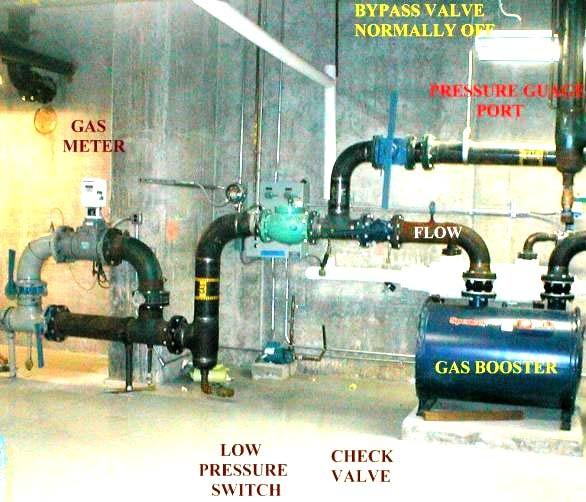
43 SECTION 18 PGW BOOSTER PUMP INSTALLATION REQUIREMENTS 18.1 A piping plan for the proposed booster pump installation must be submitted to PGW s Marketing Department before work begins All gas compressor booster pumps shall be installed and maintained according to the manufacturer s instruction A gas-air check valve must always be installed ahead of the booster pump, between the pump and the meter, to prevent an accidental flow toward the meter *A manual reset low pressure sensing device must be installed between the meter and the pump to shut down the booster in the event of low inlet pressure If several appliances are not on the same fuel line as an appliance being supplied gas at an elevated pressure from a booster pump, a bypass is recommended around the booster pump provided that the appliances can operate on low pressure The method of connection between the inlet valve and the booster pump and the outlet of the booster pump and the fuel line shall be made as specified in the sketch in exhibit F. The Field Services Department must approve any variation to the method of connection Any questions regarding the booster pump requirements can be addressed by calling 215~ Monday through Friday between the hours of 7:00 A.M. and 3:30 P.M A booster pump will run continuously unless it is interlocked with the appliances the booster supplies. It is recommended that the booster pump be wired through a control panel interlocked with the equipment that needs to operate at elevated pressure. *Acceptable Pressure Switch: Honeywell C437E1038 or equivalent. Break on pressure fall, ½ to 5½ W.C. Control should be set at 3.5 W.C
44 - 44 -

45 LOW CAPACITY BOOSTPAK

46 HIGH CAPACITY BOOSTPAK
47 SECTION 19 COMMERCIAL AND INDUSTRIAL TURN ON 19.1 All appliances must be installed and ready before gas is turned on. If this cannot be accomplished and the customer needs gas for heat to complete inside work, the Supervisor of the Commercial/Industrial Section must be contacted for approval at / Ansul valves, if installed, must be visible. If this cannot be accomplished, the Supervisor, Commercial/Industrial Section, must make approval Ansul valves, if installed, must be charged at time of turn-on for Gas to be turned on A solenoid valve for cooking equipment can be located in a drop ceiling as long as reset is accessible All fuel lines going through floors in kitchens must be sleeved. This prevents water used to clean floors from coming in contact with fuel line and corroding it
48 SECTION 20 FLEXIBLE CONNECTORS ON APPLIANCES Flexible metal appliance connectors are permitted to connect gas appliances if the connector meets ANSI.Z21.24 (stationary appliance) or ANSI.Z21.69 (movable appliance) standards. The flexible connector should not be run into a house heater cabinet. Rigid pipe must be used to extend the control piping outside the cabinet to the connector. A shutoff valve is required upstream of all flexible metal appliance connectors. Also a restraining device (exhibit C) must be attached on all movable appliances. NOTE: (1) The ANSI.Z21.24 flexible connector is the one used on domestic appliances. (2) A Sediment trap is required on all gas utilization equipment (exception: Gas range, Domestic Dryer and movable appliances.)
49 SECTION 21 Fireplace/Outdoor Open Flame Appliance Installation Requirements (1) - Any plans to install a gas fireplace unit or any type of outdoor open flame gas appliance, such as fire pits and outdoor barbeques, must be submitted to PGW s Marketing department prior to the work. This applies to commercial spaces only such as hotels, apartment complexes, or any public gathering area. (2) - All units must be CGA or AGA approved; although PGW holds the ultimate authority to supersede their approval. If the appliance is not approved by the governing bodies mentioned above, the PGW Commercial/Industrial Section Supervisor must make the final approval. (3) - The appliance must be installed and maintained according to the manufacturer s specifications. (4) - Two safety valves/disconnect switches must be installed, so that the flow of gas to the unit can be manually stopped. One manual shutoff valve must be installed within 6 feet of the appliance. The second shutoff switch must have a solenoid valve interlock with an emergency shutoff button where designated personnel can easily shutoff the gas in the case of an emergency. This emergency shutoff button is to be installed at the point of exit/egress. If this is infeasible to do, the PGW Commercial/Industrial Section Supervisor must make the approval. (5) - If there are multiple fireplace units in the same area, then the shutoff button must stop the flow of gas to every unit. (6) - All exceptions to these above-mentioned standards must be approved by the PGW Commercial/Industrial Section Supervisor. (7) - Any questions or clarifications regarding the fireplace installation requirements can be addressed by calling or Monday through Friday between the hours of 7:00 A.M. and 3:30 P.M
50 EXHIBITS Exhibit A - Bollard Standard Instructions Materials 1. Place Pa One Call (POC) Ticket, by dialing 811, a minimum of 3 business days before excavating the post hole for the bollard. 2. Dig post hole for bollard See figure above for dimensions. Black Steel Pipe, SCH 40, electric resistant Welded API 5L, Grade B 3. Partially fill hole with concrete mix. 4. Insert Steel Pipe. Size Wall Thickness PGW Code # Fill hole. 6. Fill pipe with concrete mix. Concrete Mix PGW Code # Support bollard and protect from damage while concrete cures. Sand Mix Aluminum Paint PGW Code # PGW Code # Paint with appropriate paint. Green or yellow paint PGW Code # Maintain 4 foot maximum distance for bollards from center line. Note: Bollards are to be placed at a minimum of 3 feet from protected object, except when deemed infeasible
51 EXHIBT B Three Meter Header
52 EXHIBIT-C
53 EXHIBIT-D
54 EXHIBIT-E A Ball Valve is not needed on pressures 14 W.C. or lower. Note: 3 Min. must be maintained if ball vale is not used
55 EXHIBIT F- Booster
56 Exhibit G Diversity Factors Over Ranges 100% 80% 60% 50% 40% 35% 30% 25% 20% 15% 10% Water 100% 90% 80% 70% 65% 60% 55% 50% 45% 40% 30% Heater Dryer 100% 80% 60% 50% 40% 35% 30% 25% 20% 15% 10% Heaters 100% 100% 100% 95% 90% 85% 85% 80% 80% 75% 75% Bunsen Burner 100% 95% 90% 85% 80% 75% 70% 65% 60% 55% 50%
 SUPPLEMENT January 2010-57")
57 PHILADELPHIA GAS WORKS FIELD SERVICES DEPARTMENT POLICY & REQUIREMENTS FOR CORRUGATED STAINLESS STEEL TUBING (CSST) SUPPLEMENT January
58 CORRUGATED STAINLESS STEEL TUBING (CSST) Maximum Allowable Pressure All CSST material intended for use, as a fuel line must be approved by CSA for that application. Currently, all approved CSST materials are rated for use up to a maximum operating pressure of 5 PSI. CSST material will fall under the same guidelines as rigid pipe as required by PGW s Piping Specification Guide. This particularly applies to the requirements for fuel lines carrying elevated gas pressures and the requirement that these fuel lines must be welded. PGW will permit the following exception regarding the use of CSST and elevated gas pressure in the customer s fuel line. When using CSST at elevated pressures (14 WC and above) PGW will permit the installation of a continuous length of CSST tubing that extends from the outlet of the meter to the point the fuel line is connected to the appliance. Also, the CSST must be exposed or installed in a ventilated chase. PGW will not approve any installation of CSST with a gas pressure 14 WC or above that contains threaded fittings. The installer must use the manufacturer's recommended fittings to connect the CSST tubing to the outlet of the gas meter and the CSST tubing to the appliance. It is recognized that the connection at the utilization equipment will require a shut-off cock, an appliance regulator and a union. Therefore, the use of a threaded nipple will be permitted to make the connection to the appliance. Typical Connection at an Appliance CSST Fitting High Ball Valve Regulator Low Pressure Union Configuration of threaded pipe (Max. 24 )
59 A. Introduction Corrugated Stainless Steel Tubing (CSST) is becoming increasingly popular in the gas industry. There are a number of different companies manufacturing CSST, each incorporating their own patented connection process. Therefore, mixing of materials (one manufacturers tubing using another manufacturers fittings) is not permitted. To install a particular manufacturers product, a certification is required proving you have passed an installation and guideline course conducted by a certified representative of that particular product. Being certified to install one particular manufacturer s product does not qualify a person to install another manufacturers product. The installer must be certified on the product he/she intends on installing. Where a conflict exists between manufacturers guideline and local codes, local code will always prevail. CSST tubing is CSA (formerly AGA) approved as an alternative to traditional rigid, iron pipe. CSST is also approved to handle a maximum operating pressure not to exceed 5 PSI. Unless otherwise listed in this guideline, CSST will fall under the same general rules and guidelines governing the use of rigid, iron fuel line by Philadelphia Gas Works. This is particularly the case regarding piping test; CSST shall not be treated any different than hard pipe in regards to leak testing. Individual product lines also offer accessory products such as striker plates, outdoor termination fittings, manifolds, regulators etc. When specifically required, these products should be used, especially when protection of the CSST is concerned. For example, passing through studding material (wood or metal) a striker plate must be used. When passing through metal framing, protection must be offered to protect the product from the sharp metal edge. CSST "pre-fabricated" pipe manifolds are not required to be used by the installer. CSST installed underground must be approved by the Industrial Supervisor before being installed. Call or CSST installation issues dating before release of these guidelines (pre-existing conditions) will be addressed on a case by case basis with decision making authority belonging to FSD General Supervisor position or above. It would be impossible for this guideline to anticipate and cover every possible variation in housing configurations and construction applications, which are not covered in this guide
60 For applications beyond the scope of the guide, contact the PGW technical support at or or the particular manufacturer. B. Residential vs. Commercial vs. Industrial Dwellings Residential applications shall be defined as any single family dwelling or multiple family dwellings where each unit has its own separate meter or one meter supplying less than five (5) units. Commercial and Industrial buildings would consist of any building not used for residential purposes. Apartment buildings having one (1) meter supplying five (5) or more units will be considered commercial. Industrial applications will consist of a property containing any one appliance with a Btu rating in excess of 500,000 Btu s. C. Maximum Allowable Pressure All CSST material is CSA approved for 5 pounds maximum operating pressure. CSST material will fall under the same guidelines as hard pipe as required by PGW s Piping Specification Guide. This particularly applies to threaded and welded pipe applications and the pressure they are permitted to handle. D. Piping Tests 1. Residential Piping Tests Residential applications shall be tested in the same manner as iron pipe. Standard meter dial testing will be required on all orders whether initiating gas service or turning gas back on. When warranted and /or instructed by supervision, an alternate means of testing may be applied at the discretion of supervision or the PGW representative on the job. 2. Commercial / Industrial Piping Tests CSST tubing will fall under the same guideline as applied to rigid hard pipe. Commercial / Industrial applications shall be tested in the same manner as iron pipe. 1- ½ times the operating pressure with a minimum 3-pound test
61 E. Meter Connections 1. CSST shall not be permitted for direct connection into the meter bar (outdoor or indoor sets) or the vertical piping connected to the outlet of the meter. 2. All meter sets (INDOORS AND OUTDOORS) shall be piped in with hard rigid pipe to the CSST material. 3. For outdoor meter sets, an outdoor termination fitting (supplied by the specific manufacturer) shall be used to connect CSST to the hard pipe coming off of the existing meter. No CSST should be exposed outdoors at the meter. 4. When CSST termination fitting fails to encase tubing passing through an outside wall the tubing should be sleeved with PVC, electrical conduit or iron pipe with both ends sealed
62 - 62 -
63 F. CSST Connections 1. CSST connections are approved as per IFGC and CSA for installation in a concealed location. Installation must comply with IFGC 2015 Sec Although preferable to run CSST straight and level, PGW will not enforce installation matters that are deemed unsightly by the inspector. CSST shall be properly secured with approved materials at required intervals to prevent excessive sagging in the fuel line. 3. Inter mixing CSST (hybrid connections) with standard iron pipe is permissible. For example: Placing iron pipe / fittings within a CSST system for purposes of reducing to a smaller diameter tubing or branching off in another direction. Use as Appliance Connector 1. Use of CSST materials as an appliance connector (flexible connector) is not permitted. 2. Connecting residential ranges, dryers, etc "from" CSST "to" an appliance using an approved flexible connector is permitted provided: (a) (b) (c) A termination fitting is visible above the floor or on the outside of a finished wall. Some termination fittings are designed to secure to rough framing, in these cases part of the termination fitting should be visible as proof that a CSST fitting is not embedded in the floor or wall. An appliance termination fitting is secured above the floor or on the outside of finished wall. An appliance shut-off valve is installed exiting the flange mount fitting for movable appliances
64 Floppy Steel Conduit Mounting Brace Termination Fitting Moveable Appliance Shut-Off Valve Appliance Connector 3. Connecting fixed appliances (house heaters, water heaters, etc) with CSST is permitted provided. (a) (b) (c) A flange mount termination fitting is secured above the floor or on the outside of a finished wall when encountered. At this point rigid iron pipe should then connect to the appliance. Use of an approved flexible connector is permitted provided a "rigid, iron pipe" exits the appliance and a shut-off valve is provided upstream from the appliance connector. Note: The CSST connection fitting is not to be considered a union; CSST manufacturers do not recommend frequent disassembly and assembly. A sediment trap is still required at all fixed appliances. Regarding appliance connections from above, CSST will be permitted to supply a fixed appliance provided the appliance has rigid pipe entering the gas control consisting of an appliance shut-off valve, union, and sediment trap. CSST material must then be secured to the casing of the appliance so as to prevent sagging and / or the chance possibility of a person or object pulling the tubing
65 CSST Must be secured to casing of appliance Shut-off valve Drip leg -sediment trap Union 4. CSST Supplying Roof-top Equipment (a) (b) (c) (d) (e) CSST is permitted to pass through a roof to supply roof top equipment. PGW code requires a condensate drip whenever piping passes from a heated space to a cold space. CSST will be permitted to run horizontally along the roof. CSST must be installed per manufacturer s specifications. PGW will still require sediment trap and shutoff valve at each appliance. CSST must be sleeved both horizontally and vertically. 5. Connecting suspended appliances (Infrared Heaters, etc). (a) CSST will be permitted to connect suspended appliances provided the CSST material remains higher than 7ft from the ground
66 (b) CSST will be permitted to connect to outdoor, suspended appliances provided the exposed CSST does not exceed 3ft in length and remains at least 7ft from the ground. 6. CSST jointing two (2) lengths of hard pipe. (a) CSST is permitted to joint two (2) lengths of hard pipe. There is no minimum requirement regarding the length of CSST connecting the separate sections of pipe. 7. CSST installed in concealed locations (a) Job-sites or projects considered new construction or total rehabs should have their workmanship inspected prior to piping test and turn-on order. G. CSST Installations in Walls 1. Horizontal Runs (a) (b) (c) It is preferred that CSST enter a partition wall for vertical runs only. When it is necessary to install CSST horizontally through framing or studding, precautions should be taken to protect CSST from the damage of nails, etc. Striker plates should be installed affording protection not less then 3" on each side of the stud material where CSST passes through. Any exposed CSST material visible between studding should be sleeved in floppy wound conduit or iron pipe. 2. Vertical Runs NOTE: CSST passing horizontally through metal framing material must be protected where the tubing passes through along the sharp metal edge. Preferred methods of protection should be either a RUBBER or PLASTIC GROMMETS, CHASE BUSHING, SPLIT TUBING, SPIRAL TUBING. (a) (b) CSST installed vertically inside a framed wall shall be protected from damage up to 3" from where CSST passes through "footer" framing or header framing. DO NOT secure CSST to framing (wood or metal) with clamps; CSST should be free to move inside the walls and between floors
67 (c) DO NOT position CSST inside the hollow portion of metal framing materials. H. CSST Located Outdoors 1. All CSST material located outdoors should be sleeved in an approved material both on horizontal and vertical runs. This material must be marked every 10ft stating "NATURAL GAS". 2. CSST material shall not be permitted to be used as a "quick disconnect" or "flexible connector" to an outdoor appliance. I. Bonding of Fuel Line 1. CSST tubing gas piping systems shall be bonded to the Electrical Services Grounding Electrode System. 2. Bonding shall be accomplished using a bonding clamp positioned around the metallic lock nut of the CSST. 3. The bonding stumper shall not be smaller than 6 AWG copper wire

68 Supplement: LOKRING
69 - 69 -
70 NATURAL GAS ODOR FADE & PURGING Philadelphia Gas Works (PGW) would like contractors and plumbers working with Natural Gas to keep in mind the following important safety messages regarding odor fade and purging. ODOR FADE Even though odorant is added to natural gas, contractors should not rely solely on the sense of smell to determine if natural gas is present in the ambient air of a work space. This is because it may be possible that: 1. Some individuals suffer an impaired sense of smell (chronic or transient) and cannot detect the odorant; 2. The odorant can at times be masked by other odors present in buildings or on the job site; 3. Some individuals who have worked around natural gas odorant for an extended period of time may suffer from odor fatigue and may be unable to recognize the presence or change in odor levels; and 4. In some rare cases, odor fade (loss of gas odorant) may occur making it difficult to detect the presence of natural gas in the air. In general, odor fade occurs when physical and/or chemical processes cause the level of odorant in the gas to be reduced. Odor fade can occur in both existing pipe and new installations but is most likely to occur in new steel pipe of larger diameters and longer lengths. Odor fade can also occur, in rare occasions, in plastic pipe and smaller and/or shorter pipe installations. In addition to pipe age, length and composite, odor fade may also be the result of the followings: 1. Configuration of fuel line piping and gas related facilities; 2. Existence of rust, moisture, and/or liquids within the piping system; and 3. Pressure and flow levels of natural gas through the piping Given the possibilities of odor fade and odor fatigue, PGW reminds contractors to: 1. Make sure natural gas fuel lines are sized correctly as oversizing may cause gas stagnation and low flow, which in turn can cause odor fade. Also, keep in mind that intermittent, little or no gas flow over extended period of time may result in the loss of gas odorant until gas flow increases or becomes more frequent; 2. Ensure there is no rust, moisture, liquids and/or other substances inside the pipes being used to construct the gas fuel lines as these can be contributing factors toward odor fade; 3. Consider the need to internally condition or internally coat new steel pipeline installations as well as additions of new piping segments before placing them into service when the abovementioned odor fade causes may be present; 4. Consult an odorant professional for possible causes/remediation if odor fade is encountered on any type of gas piping systems after installation. Likewise, contractors are reminded to utilize properly calibrated combustible gas indicators (CGIs) when working in an environment where a natural gas leak may be present or occur, or when purging out natural gas. PURGING On February 4, 2010, the U.S. Chemical Safety and Hazard Investigation Board (CSB) approved urgent safety recommendations on gas purging. In summary, the CSB has recommended that during the purging of fuel gas piping at industrial, commercial, and public facilities: 1. Purged fuel gases must be directly vented to a safe location outdoors, away from personnel and ignition sources. No purging can be done into any confined space; 2. Combustible gas detectors are used to continuously monitor the gas concentration at appropriate locations in the vicinity where purged gases are released; and 3. Personnel are trained about the problems of odor fade and odor fatigue and warned against relying on odor alone for detecting releases of fuel gases. Please be advised that PGW provides this safety message solely as a customer service. By providing this information, PGW does not assume any duty or responsibility to ensure that your activities are code compliant. Moreover, PGW reminds all contractors that they are solely responsible for understanding and complying with the most recent building, safety and fuel gas codes and all related laws and regulations when working on or near natural gas equipment. Finally, although safe practices are everyone's concern, the responsibility for monitoring and complying with changes in relevant codes, laws and regulations rests with the person or contractor performing the work, not with PGW
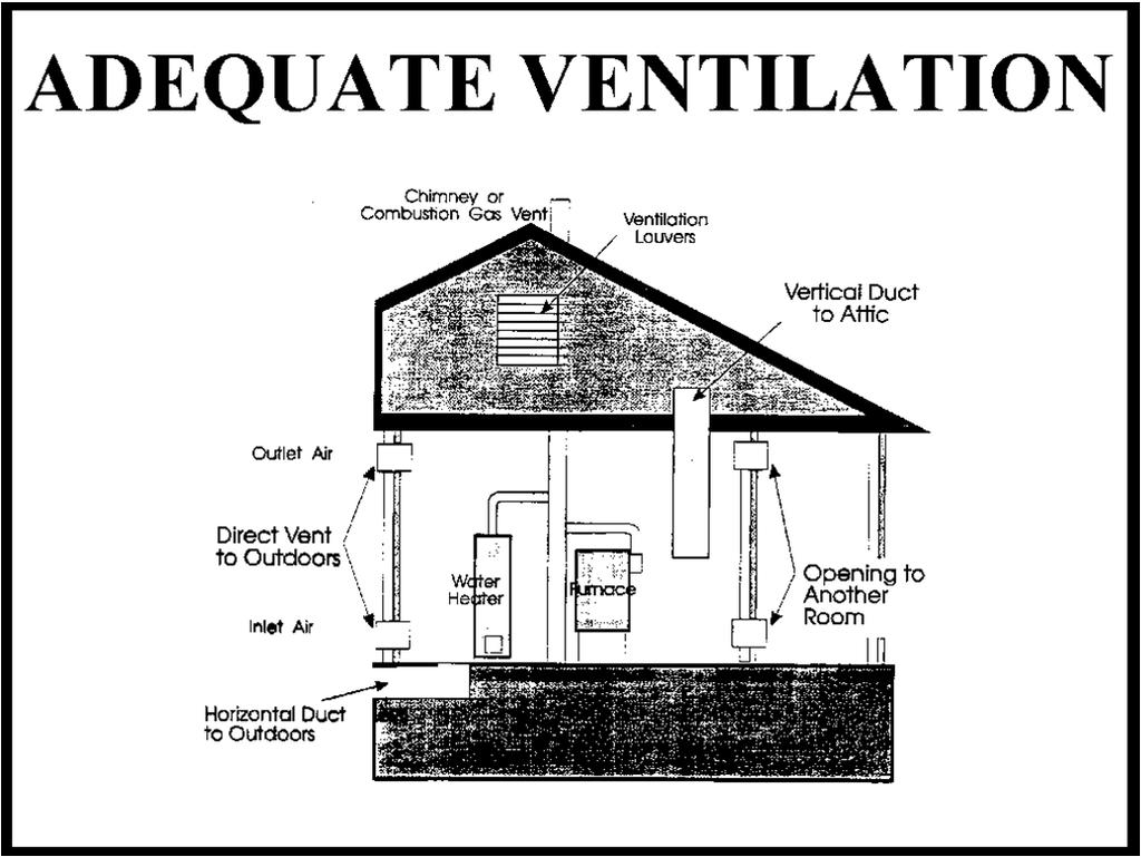
71 SUPPLEMENT PHILADELPHIA GAS WORKS FIELD SERVICE DEPARTMENT Ventilation & Combustion Air All information is referenced from: International Fuel Gas Code IFGC 2006 National Fuel Gas Code NFPA Local Codes, Policies and Procedures This information is intended strictly as a guide. For further information and/or variations, refer to your IFGC-2006, your Supervisor or FSD Training CONFINED SPACE A 100,000 Btu appliance requires 5,000 cubic feet of space 100,000 Btu divided by 20 equals 5,000 cubic feet Divide 20 into the appliance Btu input rating. The resulting number is the minimum size room required in cubic feet. If the room size in cubic feet (LxWxH) is less than this number, adequate make-up air for combustion is required
72 - 72 -
73 - 73 -
74 - 74 -
75 - 75 -
GASEOUS HYDROGEN SYSTEMS
 CHAPTER 7 GASEOUS HYDROGEN SYSTEMS SECTION 701 GENERAL 701.1 Scope. The installation of gaseous hydrogen systems shall comply with this chapter and Chapters 30 and 35 of the Fire Compressed gases shall
C O D E S & A M M E N D M E N T S
 SEVIER COUNTY UTILITY DISTRICT SEPTEMBER 2, 2014 Sevier County Utility District has adopted the 2009 International Fuel Gas Code for gas inspections. The following pages contain frequently used codes and
101 S. George St 116 E Gas Ave York, PA York, PA (717) (717)
 (717)") City of York Qdot Engineering 101 S. George St 116 E Gas Ave York, PA 17405 York, PA 17405 (717) 849-2329 (717) 744-8315 INSPECTION CHECKLIST Residential Mechanical 2009 Codes This checklist is intended
City of York Qdot Engineering 101 S. George St 116 E Gas Ave York, PA 17405 York, PA 17405 (717) 849-2329 (717) 744-8315 INSPECTION CHECKLIST Residential Mechanical 2009 Codes This checklist is intended
2015 MECHANICAL CODE REQUIREMENTS
 2015 MECHANICAL CODE REQUIREMENTS ANTRIM COUNTY BUILDING DEPARTMENT PO BOX 188 205 CAYUGA STREET BELLAIRE, MI 49615 (231) 533-8373 FAX (231) 533-6041 Mechanical requirements for residential buildings per
Inspection Checklist Mechanical Final
 Property Owner Name: Property Address: Property Parcel Number: Inspectors Name: Review Date: Permits and Plans 1. Job address is posted in a visible location. (R319.1) 2. Permit and approved plans, and
2012 INTERNATIONAL FUEL GAS CODE VENTS
 2012 INTERNATIONAL FUEL GAS CODE SECTION 502 (IFGC) VENTS 502.1 General. All vents, except as provided in Section 503.7, shall be listed and labeled. Type B and BW vents shall be tested in accordance with
Mechanical Appliance and Equipment Inspection Checklist
 34 2015 IRC Performing Residential Mechanical s Mechanical Appliance and Equipment Checklist Inspect Mechanical Appliance and Equipment Comments / I. Identify possible mechanical appliance and equipment
CHAPTER 1 ADMINISTRATION SECTION 101 (IFGC) GENERAL
 GENERAL") CHAPTER 1 ADMINISTRATION SECTION 101 (IFGC) GENERAL 101.1 Title. These regulations shall be known as the North Carolina Fuel Gas Code as adopted by the North Carolina Building Code Council on March 11,
CHAPTER 1 ADMINISTRATION SECTION 101 (IFGC) GENERAL 101.1 Title. These regulations shall be known as the North Carolina Fuel Gas Code as adopted by the North Carolina Building Code Council on March 11,
CHAPTER 8 CHIMNEYS AND VENTS
 CHAPTER 8 CHIMNEYS AND VENTS SECTION 801 GENERAL 801.1 Scope. This chapter shall govern the installation, maintenance, repair and approval of factory-built chimneys, chimney liners, vents and connectors.
CHAPTER 8 CHIMNEYS AND VENTS
 CHAPTER 8 CHIMNEYS AND VENTS SECTION 801 GENERAL 801.1 Scope. This chapter shall govern the installation, maintenance, repair and approval of factory-built chimneys, chimney liners, vents and connectors.
NFPA 54 UPDATE. Paul Cabot American Gas Association
 NFPA 54 UPDATE Paul Cabot American Gas Association PRESENTATION TOPICS Summary Listing Schedule Revisions Definitions/General Piping Appliances and Appliance Installation Venting 2015 Edition Revision
CHIMNEYS AND VENTS CHAPTER 8
 CHAPTER 8 CHIMNEYS AND VENTS SECTION 801 GENERAL 801.1 Scope. This chapter shall govern the installation, maintenance, repair and approval of factory-built chimneys, chimney liners, vents and connectors.
4.3 Installing Appliances and Interior Vapor Distribution Systems Performance-Based Skills Assessment 2016
 4.3 Installing Appliances and Interior Vapor Distribution Systems Performance-Based Skills Assessment 2016 Section One Task 1 Task 2 Task 3 Task 4 Task 5 Section Two Task 1 Task 2 Task 3 Task 4 Task 5
2012 International Fuel Gas Code Design, Installation and Inspection Principles
 Overview 2012 International Fuel Gas Code Design, Installation and Inspection Principles Based on the 2012 International Fuel Gas Code Administration Definitions General regulations Gas piping installations
Inspection Checklist Mechanical Rough in
 Property Owner Name: Property Address: Permit Number: Inspectors Name: Review Date: Permits and Plans 1. Job address is posted in a visible location. (R319.1) 2. Permit and approved plans are on site and
IFGC-2012 AMENDED IFGC-2015 IFGC-2018 CHAPTER 1 SCOPE AND
 CHAPTER 1 SCOPE AND CHAPTER 1 SCOPE AND ADMINISTRATION ADMINISTRATION 301.1.2 LP-Gas installations. Whenever there is a conflict between this code and NFPA 54 and B+NFOA 58 as adopted by the Nevada LP-Gas
NATURAL GAS PIPING
 SECTION 15496 - NATURAL GAS PIPING PART 1 - GENERAL 1.01 RELATED DOCUMENTS A. Drawings and general provisions of the Contract, including General and Supplementary Conditions and Division 1 Specification
Introduction Service Pipe Application Important Terms Air Requirements... Appliance Location... Venting... Calculations...
 Construction Guide Table of Contents Page Introduction... 2 Service Pipe Application... 4 Important Terms... 5 Air Requirements... Appliance Location... Venting... Calculations... 37 Gas Distribution System...
B. HI Compliance: Design, manufacture, and install pumps in accordance with HI "Hydraulic Institute Standards."
 PART 1: GENERAL 1.01 Purpose: A. This standard is intended to provide useful information to the Professional Service Provider (PSP) to establish a basis of design. The responsibility of the engineer is
GENERAL BASIC INSTALLATION INSTRUCTIONS DIRECT FIRED HOT WATER BOILERS PARKER BOILER CO.
 GENERAL BASIC INSTALLATION INSTRUCTIONS DIRECT FIRED HOT WATER BOILERS PARKER BOILER CO. GBI 201-5 3C For a proper installation and in order to receive the best in operating life and efficiency from your
Chapter FUEL GAS CODE*
 Chapter 19.09 FUEL GAS CODE* * Editors Note: Serial No. 2004-31, 1, adopted Oct. 11, 2004 amended Title 19 in its entirety to read as herein set out. See the editor's note at Tit. 19 and also the Code
EL DORADO COUNTY REGIONAL FIRE PROTECTION STANDARD
 EL DORADO COUNTY REGIONAL FIRE PROTECTION STANDARD INSTALLATION OF COMMERCIAL FIRE SPRINKLER SYSTEMS STANDARD #C-001 EFFECTIVE 03-25-2009 PURPOSE: To ensure that sprinkler plans submitted for review contain
Errata ANSI Z223.1 National Fuel Gas Code 2015 Edition
 Errata ANSI Z223.1 National Fuel Gas Code 2015 Edition Reference: Various Errata Z223.1-2015-1 Issue Date: 3/10/16 National Fuel Gas Code user: The American Gas Association (AGA) notes the following errors
D. NEMA Compliance: Provide electric motors and components which comply with NEMA standards.
 PART 1: GENERAL 1.01 Purpose: A. This standard is intended to provide useful information to the Professional Service Provider (PSP) to establish a basis of design. The responsibility of the engineer is
TABLE OF CONTENTS Limitations of Authority...6 Table Swimming Pool, Spa, and Hot Tub Permit Fees...7
 TABLE OF CONTENTS CHAPTER 1 ADMINISTRATION..............1 101.0 General.......................1 101.1 Title..........................1 101.2 Scope........................1 101.3 Purpose......................1
C. ASSE 1013: Performance Requirements for Reduced Pressure Principle Backflow Preventers.
 SECTION 22 10 00 PLUMBING PIPING AND PUMPS PART 1 - GENERAL 1.1 Purpose: A. This standard is intended to provide useful information to the Professional Service Provider (PSP) to establish a basis of design.
SECTION PLUMBING EQUIPMENT
 PART 1 GENERAL 1.1 SECTION INCLUDES A. Water heaters B. Packaged water heating systems C. Water storage tanks D. Water softeners E. Pumps F. Circulators 1.2 REFERENCES SECTION 22 30 00 PLUMBING EQUIPMENT
Do not use this vent pipe or fittings for venting incinerators of any kind.
 ! CAUTION! Do not use this vent pipe or fittings for venting incinerators of any kind. C.S.A. Certified For Natural Gas Or Propane Tested For 100 LBS. ASME Working Pressure For correct installation of
HVAC Equipment Access Equipment Location
 City of Lancaster- Building Department 121 East Chestnut Street, Suite 102, Lancaster, Ohio 43130-3825 (740) 687-6649, Fax (740) 681-5030 Web site: www.ci.lancaster.oh.us/dept/building HVAC Heating, Ventilating,
2012 Virginia Residential Fuel Gas Code & 2012 International Fuel Gas Code Update Training
 2012 Virginia Residential Fuel Gas Code & 2012 International Fuel Gas Code Update Training ----------------------------- Henrico County Department of Building Construction and Inspections Before we begin
2012 Virginia Residential Fuel Gas Code & 2012 International Fuel Gas Code Update Training
 2012 Virginia Residential Fuel Gas Code & 2012 International Fuel Gas Code Update Training ----------------------------- Henrico County Department of Building Construction and Inspections Before we begin
VENTING GAS APPLIANCES NFPA 54 CODE
 VENTING GAS APPLIANCES NFPA 54 CODE Better Buildings: Better Business Robert Parkhurst March 3, 2017 Objectives Standardize terminology Examine gas piping size and safety Simplify design rules Selection
GENERAL BASIC INSTALLATION INSTRUCTIONS INDIRECT GAS FIRED WATER HEATERS PARKER BOILER CO.
 GENERAL BASIC INSTALLATION INSTRUCTIONS INDIRECT GAS FIRED WATER HEATERS PARKER BOILER CO. GBI 210 3C For a proper installation and in order to receive the best in operating life and efficiency from your
Adopting Agency BSC SFM. Adopt Entire Chapter X X X X X X X X X X Adopt Entire Chapter as amended (amended sections listed below)
") CALIFORNIA MECANICAL CODE MATRIX ADOPTION TABLE CAPTER CIMNEY AND VENTS Adopting Agency BSC SFM CD DSA OSPD 1 1/AC AC SS SS/CC 1 4 Adopt Entire Chapter X X X X X X X X X X Adopt Entire Chapter as amended
CALIFORNIA MECANICAL CODE MATRIX ADOPTION TABLE CAPTER CIMNEY AND VENTS Adopting Agency BSC SFM CD DSA OSPD 1 1/AC AC SS SS/CC 1 4 Adopt Entire Chapter X X X X X X X X X X Adopt Entire Chapter as amended
STEAM AND CONDENSATE PIPING AND PUMPS DESIGN AND CONSTRUCTION STANDARD
 PART 1: GENERAL 1.01 Purpose: A. This standard is intended to provide useful information to the Professional Service Provider (PSP) to establish a basis of design. The responsibility of the engineer is
Design and Construction Standards SECTION PLUMBING EQUIPMENT
 SECTION 15450 PLUMBING EQUIPMENT PART 1 GENERAL 1.1 SECTION INCLUDES: A. Water heaters. B. Packaged water heating systems. C. Water storage tanks. D. Water softeners. E. Pumps. F. Circulators. 1.2 REFERENCES
FOR YOUR SAFETY WARNING
 6-583.4 5H80004A July, 2011 installation and service manual gas-fired unit heaters model HD and HDB WARNING 1. Improper installation, adjustment, alteration, service, or maintenance can cause property
INSTALLER'S GUIDE MASONRY CHIMNEY VENT KIT WARNING: BAYVENT800B 18- CH23D2-05
 INSTALLER'S GUIDE IMPORTANT This Document is customer property and is to remain with this unit. Please return to service information pack upon completion of work. Model: BAYVENT800B For use with Category
Power-Fin 4:1 HOT WATER HEATING BOILERS DOMESTIC HOT WATER SUPPLY BOILERS 1,500,000, 1,700,000 and 2,000,000 Btu/hr MODELS
 PBE/PFE-i&s-03 INSTALLATION AND SERVICE MANUAL Power-Fin 4:1 HOT WATER HEATING BOILERS DOMESTIC HOT WATER SUPPLY BOILERS 1,500,000, 1,700,000 and 2,000,000 Btu/hr MODELS FIG. 1 Front View 1,500,000-2,000,000
POWER VENT. Standard Power Vent, Fan Type Unit Heaters: Standard Power Vent, Blower Type Unit Heaters: General WARNING WARNING. Model UDAP & Model APD
 General APPLIES TO: Standard Power Vent, Fan Type Unit Heaters: Model UDAP & Model APD Standard Power Vent, Blower Type Unit Heaters: Model UDBP Form I-UD&APD Series-V-PV (05-17) Obsoletes I-UD&APD Series-V-PV
SECTION (15486) - FUEL-FIRED, DOMESTIC WATER HEATERS
 - FUEL-FIRED, DOMESTIC WATER HEATERS") SECTION 22 34 00 (15486) - FUEL-FIRED, DOMESTIC WATER HEATERS System shall provide a complete hot water return throughout the entire system with balancing (flow control) valves not less than 10 feet from
SECTION 22 34 00 (15486) - FUEL-FIRED, DOMESTIC WATER HEATERS System shall provide a complete hot water return throughout the entire system with balancing (flow control) valves not less than 10 feet from
CHAPTER LOCAL AMENDMENTS TO THE INTERNATIONAL MECHANICAL CODE 2000 EDITION
 CHAPTER 23.20 LOCAL AMENDMENTS TO THE INTERNATIONAL MECHANICAL CODE 2000 EDITION SECTIONS 23.20.100 Local Amendments To The International Mechanical Code, 2000 Edition 23.20.202 Definitions 23.20.301.14
Section 2, Reference publications: Updated the referenced publications to the current editions.
 Summary of Substantive Changes between the 2014 and the 2015 editions of ANSI Z21.10.3 CSA 4.3 Gas fired water heaters, volume III, storage water heaters with input ratings above 75,000 Btu per hour, circulating
SPECIFIC APPLIANCES CHAPTER 6
 CHAPTER 6 SPECIFIC APPLIANCES SECTION FGC 601 GENERAL 601.1 Scope. This chapter shall govern the approval, design, installation, construction, maintenance, alteration and repair of the appliances and equipment
BUILDING CODE GUIDELINE FOR MECHANICAL INSPECTIONS
 BUILDING CODE GUIDELINE FOR MECHANICAL INSPECTIONS Building Code compliance is the obligation of design professionals and/or contractors. Plan Review and Inspection Guidelines are intended to be used by
SPECIFIC APPLIANCES, FIREPLACES AND SOLID FUEL-BURNING EQUIPMENT
 CHAPTER 9 SPECIFIC APPLIANCES, FIREPLACES AND SOLID FUEL-BURNING EQUIPMENT SECTION 901 GENERAL 901.1 Scope. This chapter shall govern the approval, design, installation, construction, maintenance, alteration
GAS FIRED BOILERS FOR FORCED HOT WATER VENTING ADDENDUM. ECR International Ltd. - Olsen Division P.O. Box 900 Wallaceburg, Ont.
 ODV-B GAS FIRED BOILERS FOR FORCED HOT WATER VENTING ADDENDUM ECR International Ltd. - Olsen Division P.O. Box 900 Wallaceburg, Ont. N8A5E5 TABLE OF CONTENTS HORIZONTAL PIPING... PAGES 1-10 WARNINGS...
INSTALLATION AND OPERATING INSTRUCTIONS TABLE OF CONTENTS IMPORTANT
 C US This manual must be left with owner and should be hung on or adjacent to the boilerfor reference. COMMON VENTING MODELS CHS-300 through CHS-399 INSTALLATION AND OPERATING INSTRUCTIONS TABLE OF CONTENTS
FOR YOUR SAFETY WARNING FOR YOUR SAFETY. high efficiency, separated combustion gas-fired unit heaters models PTC and BTC
 6-563.7 5H0807150000 November, 2014 Model PTC installation and service manual high efficiency, separated combustion gas-fired unit heaters models PTC and BTC WARNING 1. Improper installation, adjustment,
FOR YOUR SAFETY WARNING
 6-583.7 5H8000400000 August, 2014 installation and service manual gas-fired unit heaters model HD and HDB WARNING 1. Improper installation, adjustment, alteration, service, or maintenance can cause property
CHAPTER LOCAL AMENDMENTS TO THE INTERNATIONAL FUEL GAS CODE 2009 EDITION.
 CHAPTER 23.110 LOCAL AMENDMENTS TO THE INTERNATIONAL FUEL GAS CODE 2009 EDITION. 23.110.100 Local amendments to the International Fuel Gas Code, 2009 Edition. 23.110.101.2 Scope. 23.110.103 23.110.110.
A. ASME Compliance: Fabricate and install hydronic piping in accordance with ASME B31.9 "Building Services Piping.
 PART 1: GENERAL 1.01 Purpose: A. This standard is intended to provide useful information to the Professional Service Provider (PSP) to establish a basis of design. The responsibility of the engineer is
Inspection Checklist Residential Mechanical Rough In July 2016
 Inspection Checklist Residential Mechanical Rough In July 2016 This Inspection Checklist reflects code requirements of the 2015 International Residential Code (IRC), the 2015 Uniform Plumbing Code (UPC),
Back to back. Cascade Venting System for RTG 199HE. Basic Set for units 1 and Installation instructions
 Installation instructions Cascade Venting System for RTG 199HE Back to back Basic Set for units 1 and 2-7 736 501 253 6 720 811 762 / 238-50973-00A (2014/05) Table of contents Table of contents 1 Key to
FOR YOUR SAFETY WARNING
 6-584.11 5H0800020000 May, 2017 INSTALLATION AND SERVICE MANUAL separated combustion gas-fired unit heaters model HDS and HDC WARNING 1. Improper installation, adjustment, alteration, service or maintenance
FOR YOUR SAFETY W ARNING IMPORTANT FOR YOUR SAFETY. INSTALLATION AND SERVICE MANUAL power vented gas-fired unit heaters model PTP
 6-560.7 5H0801050000 May, 2017 INSTALLATION AND SERVICE MANUAL power vented gas-fired unit heaters model PTP 1. Improper installation, adjustment, alteration, service, or maintenance can cause property
CITY OF PASADENA FIRE DEPARTMENT
 Page 1 of 8 CITY OF PASADENA FIRE DEPARTMENT INSTALLATION OF COMMERCIAL SPRINKLERS (Revised 12/10/2014) SCOPE: This standard applies to the design and installation of automatic fire sprinkler systems in
City of Elizabethtown
 City of Elizabethtown Natural Gas Department Plans and Specifications for Gas Service Piping Installations (270)765-6121 Table of Contents Third-Party Damage Prevention p.3 Introduction p.4 General Coverage
NAVIEN AMERICA INC FITCH AVENUE IRVINE, CALIFORNIA, USA
 Navien America Inc. Specification Details for the Navien models: CR-210 CR-210A For Indoor Installation Only For Potable Water Heating and Space Heating NAVIEN AMERICA INC. 17855 FITCH AVENUE IRVINE, CALIFORNIA,
DIVISION 21 - FIRE SUPPRESSION
 DIVISION 21 - FIRE SUPPRESSION DESIGN CRITERIA It is the policy of UC Davis to install fire sprinkler systems in all new construction/facilities. If the building is classified as a pole barn, shed, carport,
Code verification sign-off
 Code verification sign-off Following is a list of the most common manufactured home code non-compliant items found in used or altered manufactured homes. These are only the most commonly found items and
VENTING CLEARANCES. BBT NORTH AMERICA Bosch Group. Bosch Water Heating 340 Mad River Park, Waitsfield, VT TWH-V-26 page 1 of 6 rev 01/06
 page 1 of 6 VENTING CLEARANCES The vents should not be obstructed and all joints properly fitted. Floors, ceilings and walls must be cut or framed to provide necessary clearance to vents. Metal strippings
Installation Instructions T 9822 Gas Dryer. en - US, CA. To prevent accidents
 Installation Instructions T 9822 Gas Dryer To prevent accidents en - US, CA and appliance damage read these instructions before installation or use. M.-Nr. 07 431 110 2 WARNING For your safety the information
Venting of Gas Fired Equipment RV
 PLEASE DO NOT BOOKMARK ANY ANYTIMECE WEBPAGES! Our system will remember the last page you viewed when logging out and back in but please DO NOT exit out when taking a test. Your place will NOT be saved.
FLANGED CORR/GUARD CORR/GUARD INSTALLATION INSTRUCTIONS
 CORR/GUARD INSTALLATION INSTRUCTIONS This symbol on the nameplate means this product is listed by Underwriters Laboratories Inc. Tested to UL1738 / CAN / ULCS636-08 Listing No. MH26687 Testing No. 11EN
IMC Significant Changes Summary Tier I
 2009-2015 IMC Significant Changes Summary Tier I 202 Environmental Air The definition of environmental air has been expanded through the addition of parking garage exhaust. 306.1 Access More than just
SECTION COMPRESSED AIR SYSTEM. A. Pipe and pipe fittings, including valves, unions and couplings.
 SECTION 15481 COMPRESSED AIR SYSTEM PART 1 - GENERAL 1.1 SECTION INCLUDES A. Pipe and pipe fittings, including valves, unions and couplings. B. Air compressor. C. After cooler. D. Refrigerated air dryer.
REFRIGERANT PIPING SYSTEM
 PART 1 GENERAL 1.01 DESCRIPTION A. The requirements of this section apply to the refrigerant piping system connecting refrigeration and HVAC equipment specified in other sections of these specifications.
Side by side. Cascade Venting System for RTG 199HE. Extension Set for units 3 or Installation instructions
 Installation instructions Cascade Venting System for RTG 199HE Side by side 6720804520-20.1V Extension Set for units 3 or 4-7 736 501 254 6 720 811 761 / 238-50976-00A (2014/05) Table of contents Table
REFRIGERANT PIPING
 SECTION 232300 - REFRIGERANT PIPING PART 1 - GENERAL 1.1 RELATED DOCUMENTS A. Drawings and general provisions of the Contract, including General and Supplementary Conditions and Division 01 Specification
2018 National Fuel Gas Code Summary List of Revisions Updated: 7/27/17
 The following list contains a summary of the significant revisions in the 2015 National Fuel Gas Code approved by the National Fuel Gas Code Committee, ANSI ASC Z223 and NFPA 54. 1.1.1.1 (B), (C), & (D)
CHAPTER 9 SPECIFIC APPLIANCES, FIREPLACES AND SOLID FUEL BURNING EQUIPMENT
 CHAPTER 9 SPECIFIC APPLIANCES, FIREPLACES AND SOLID FUEL BURNING EQUIPMENT SECTION 901 GENERAL 901.1 Scope. This chapter shall govern the approval, design, installation, construction, maintenance, alteration
CHAPTER LOCAL AMENDMENTS TO THE INTERNATIONAL MECHANICAL CODE 2012 EDITION
 CHAPTER 23.20 LOCAL AMENDMENTS TO THE INTERNATIONAL MECHANICAL CODE 2012 EDITION Sections 23.20.100 Local amendments to the International Mechanical Code, 2012 Edition.... 2 23.20.101.2 Scope.... 2 23.20.103-110
Vent Supplement Ultra-80, -105, -155, -230 & -310
 Gas-fired water boiler Vent Supplement Ultra-80, -105, -155, -230 & -310 Installation of: Vent piping Air piping with This document must only be used by a qualified heating installer/service technician.
INSTALLATION AND SERVICE MANUAL
 INSTALLATION AND SERVICE MANUAL HORIZONTAL COMBUSTION AIR INLET KITS CATEGORY III VENTING FOR SEPARATED COMBUSTION TUBULAR GAS FIRED UNIT HEATERS USE 5 INCH KIT FOR UNITS WITH CAPACITIES 100,000 TO 250,000
1 Exam Prep Florida Building Code-Mechanical Tabs and Highlights
 1 Exam Prep Florida Building Code-Mechanical Tabs and s These 1 Exam Prep Tabs are based on Florida Building Code-Mechanical, 2014. Each 1 Exam Prep tabs sheet has five rows of tabs. Start with the first
Model ESFR-17 Dry Type Pendent Sprinklers Early Suppression Fast Response 16.8 K-factor General Description
 Technical Services 800-381-9312 +1-401-781-8220 www.tyco-fire.com Model ESFR-17 Dry Type Pendent Sprinklers Early Suppression Fast Response 16.8 K-factor General Description The TYCO Model ESFR-17 Dry
INSTALLATION AND SERVICE MANUAL
 INSTALLATION AND SERVICE MANUAL VERTICAL COMBUSTION AIR INLET KITS CATEGORY III VENTING FOR SEPARATED COMBUSTION TUBULAR GAS FIRED UNIT HEATERS USE 5 INCH KIT FOR UNITS WITH CAPACITIES 100,000 TO 250,000
SECTION DUCTWORK
 PART 1 GENERAL 1.1 REFERENCES SECTION 23 31 00 DUCTWORK A. ASHRAE - Handbook, Duct Design B. ASHRAE - Handbook, Duct Construction C. ASTM A90/A90M - Standard Test Method for Weight (Mass) of Coating on
SPECIFIC APPLIANCES CHAPTER 6
 CHAPTER 6 SPECIFIC APPLIANCES SECTION 601 (IFGC) GENERAL 601.1 Scope. This chapter shall govern the approval, design, installation, construction, maintenance, alteration and repair of the appliances and
MODELS B1PA024, 030 AND 036
 STELLAR 2000 SINGLE PACKAGE HEAT PUMPS INSTALLATION INSTRUCTION Supersedes: 511.26-N1Y (892) 511.26-N1Y (893) MODELS B1PA024, 030 AND 036 035-11622 GENERAL YORK Model B1PA units are factory assembled heat
Analysis of Changes for the 5 th Edition (2014) of the Florida Codes
 of the Florida Codes") Analysis of Changes for the 5 th Edition (2014) of the Florida Codes Changes to the Florida Building Code, Fuel-Gas This Analysis of Changes for the 5 th Edition (2014) of the Florida Codes is intended
Analysis of Changes for the 5 th Edition (2014) of the Florida Codes Changes to the Florida Building Code, Fuel-Gas This Analysis of Changes for the 5 th Edition (2014) of the Florida Codes is intended
DIVISION 23 HVAC Hydronic Piping Systems
 General Information Programming/ Design Bidding/ Preconstruction Installation/ Construction Closeout/ Warranty QA/QC Checklist Construction Services DIVISION 23 HVAC 23 21 13 Hydronic Piping Systems 01
NITROGEN-GENERATING SPRINKLER CORROSION INHIBITING SYSTEM
 NITROGEN-GENERATING SPRINKLER CORROSION INHIBITING SYSTEM PART 1 - GENERAL 1.1 SUMMARY A. This section outlines the requirements for the nitrogen-generating sprinkler corrosion inhibiting system. The work
2015 & 2012 International Mechanical Code Significant Changes and the PA Uniform Construction Code
 2015 & 2012 International Mechanical Code Significant Changes and the PA Uniform Construction Code Welcome! Shawn Strausbaugh Director PMG Technical Resources ICC Government Relations sstrausbaugh@iccsafe.org
FACT SHEET 2018 National Fuel Gas Code Summary List of Revisions rev
 This fact sheet provides an overview of the significant revisions in the 2015 National Fuel Gas Code approved by the National Fuel Gas Code Committee, ANSI ASC Z223 and NFPA 54. These revisions are published
INSTALLATION AND OPERATION MANUAL GAS SKILLETS MODELS: GTS-30 GTS-40
 INSTALLATION AND OPERATION MANUAL GAS SKILLETS MODELS: GTS-30 GTS-40 CROWN FOOD SERVICE EQUIPMENT LTD. 70 OAKDALE ROAD, DOWNSVIEW, (TORONTO), ONTARIO, CANADA, M3N 1V9 TELEPHONE: (416) 746-2358, FAX: (416)
SAMPLE SPECIFICATION FOR RIELLO ARRAY MODULATING BOILER
 SAMPLE SPECIFICATION FOR RIELLO ARRAY MODULATING BOILER PART 1 GENERAL 1.01 RELATED DOCUMENTS A. ANSI Z21.13 American National Standard for Gas-Fired Low Pressure Steam and Hot Water Boilers B. ASME Section
SECTION LABORATORY EQUIPMENT CONSTRUCTION STANDARD PART 1: GENERAL Scope of Standard
 PART 1: GENERAL 1.01 Scope of Standard A. This standard provides general guidance concerning the specific preferences of the University of Texas at Austin for safety equipment used in or in support of
B. Product Data: Provide manufacturers catalogue information. Indicate valve data and ratings.
 DIVISION 21 21 05 00 COMMON WORK RESULTS FOR FIRE SUPPRESSION PART 1 GENERAL 1.1 SECTION INCLUDES A. Pipe, fittings, sleeves, escutcheons, seals, and connections for sprinkler systems. 1.2 RELATED REQUIREMENTS
ICP Plumbing Exam. Name: Carefully read each question and then circle the letter of the best answer.
 ICP Plumbing Exam Name: Date: Score: Carefully read each question and then circle the letter of the best answer. 1. A 1 inch diameter faucet, where the inside edge of the spout opening is 2.5 inches away
Corr/Guard PRESSURE RATED VENTING SYSTEM IMPORTANT: DO NOT INSTALL WITHOUT FIRST READING THESE INSTRUCTIONS VERY CAREFULLY.
 CORR/GUARD INSTALLATION INSTRUCTIONS This symbol on the nameplate means this product is listed by Underwriters Laboratories Inc. Tested to UL1738 / CAN / ULCS636-1995 Listing No. MH26687 Testing No. 11EN
GWS. Venting Manual. Gas-Fired Water Boilers. Hazard definitions. Contents. Venting method definitions
 GWS Gas-Fired Water Boilers Venting Manual Hazard definitions Contents Page Hazards that will cause severe personal injury, death or substantial property damage. Hazards that can cause severe personal
esfr dry pendent sprinkler Vk501 (k14.0)
") September 13, 2012 Sprinkler 122a 1. DESCRIPTION Viking Early Suppression Fast Response (ESFR) Dry Pendent Sprinkler VK501 is a fast response fusible element type sprinkler designed for use in storage
September 13, 2012 Sprinkler 122a 1. DESCRIPTION Viking Early Suppression Fast Response (ESFR) Dry Pendent Sprinkler VK501 is a fast response fusible element type sprinkler designed for use in storage
Installation Instructions
 Single-Stage Tables For Category I Fan-Assisted Furnaces Installation Instructions NOTE: Read the entire instruction manual before starting the installation. SAFETY CONSIDERATIONS Installing and servicing
CHAPTER 7 ALTERATIONS LEVEL
 CHAPTER 7 ALTERATIONS LEVEL 2 SECTION 701 GENERAL 701.1 Scope. Level 2 alterations as described in Section 404 shall comply with the requirements of this chapter. Exception: Buildings in which the reconfiguration
SERIES 24. Series 24 Features. Commercial, Forced Draft, Hot Water or Steam Boiler. The right fit for any commercial job
 SERIES Commercial, Forced Draft, Hot Water or Steam Boiler Sizes from to,8 MBH output The right fit for any commercial job The Series is built to handle any installation - businesses, institutions, apartments,
SECTION WET-PIPE SPRINKLER SYSTEMS
 SECTION 21 13 13 WET-PIPE SPRINKLER SYSTEMS PART 1 - GENERAL 1.1 SCOPE OF WORK A. Design, installation and testing shall be in accordance with NFPA 13 except for specified exceptions. B. The demolition
ADDENDUM #3 DATE: August 8, 2018 Page 1 of 1. The Curators of the University of Missouri
 ADDENDUM #3 DATE: August 8, 2018 Page 1 of 1 TO CONTRACT DOCUMENTS ENTITLED: PROJECT MANUAL FOR: Women s and Children s Hospital New Water Service Main PROJECT NUMBER: CP172631 ADVERTISEMENT DATE: July
B. Galvanized-Steel-Sheet Sleeves: inch minimum thickness; round tube closed with welded longitudinal joint.
 (816) 373-4878 U1208-01/FAI29-029 (573) 751-2624 SECTION 2 105 17 - SLEEVES AND SLEEVE SEALS FOR FIRE-SUPPRESSION PIPING PART 1 - GENERAL 1.1 RELATED DOCUMENTS A. Drawings and general provisions of the