en Indirect-fired Air Heater. Cub 400 Cub 700 OPERATOR S MANUAL
|
|
|
- Brittney Fisher
- 5 years ago
- Views:
Transcription

1 en Indirect-fired Air Heater Cub 400 Cub 700 OPERATOR S MANUAL E N
2
3 Cub 400/700 Table of Contents 1. Foreword 3 2. Safety Information Operating Safety Operator Safety while using Combustion Burners Service Safety Safety and Operating Labels Operation System Description Installing the Lift Bar Machine Location System Component Locations Control Panel Preliminary Checks Starting the Machine Shutting Down the Machine Using the Remote Thermostat Adjusting the Recirculation System Suggested Venting Connecting the Main Electric Power Supply Installing the Plenums Checking the Burner Air Setting Maintenance Periodic Maintenance Schedule Changing and Adjusting the Supply Blower Belt Replacing the Oil Burner Nozzle Checking and Adjusting the Oil Burner Electrodes Checking the Fuel Pressure Changing the Fuel Heater Filter OIl Burner Adjustments Fuel Blend Guide Oil Burner Set-up Chart Gas Burner Set-up Chart
4 Table of Contents Cub 400/ Turbulator Setting (Head Setting) Checking and Adjusting the Gas Pressure Checking and Adjusting the Electrode and Ionization Probe Checking Function of Ionization Probe Changing Burner Orifice Transporting Gas Analyzer Access Hole List of Abbreviations Troubleshooting Wiring Diagram Technical Data Cub 400 Technical Data Cub 700 Technical Data...57 wcghi_bo en_001toc.fm 2
5 1. Foreword Foreword This manual provides information and procedures to safely operate and maintain this Ground Heaters, Inc. model. For your own safety and protection from injury, carefully read, understand and observe the safety instructions described in this manual. Keep this manual or a copy of it with the machine. If you lose this manual or need an additional copy, please contact Ground Heaters, Inc. This machine is built with user safety in mind; however, it can present hazards if improperly operated and serviced. Follow operating instructions carefully! If you have questions about operating or servicing this equipment, please contact Ground Heaters, Inc. The information contained in this manual was based on machines in production at the time of publication. Ground Heaters, Inc. reserves the right to change any portion of this information without notice. All rights, especially copying and distribution rights, are reserved. Copyright 2007 by Ground Heaters, Inc. No part of this publication may be reproduced in any form or by any means, electronic or mechanical, including photocopying, without express written permission from Ground Heaters, Inc. Any type of reproduction or distribution not authorized by Ground Heaters, Inc. represents an infringement of valid copyrights and will be prosecuted. We expressly reserve the right to make technical modifications, even without due notice, which aim at improving our machines or their safety standards. wcghi_tx000001gb diesel.fm 3
6 wcghi_tx000001gb diesel.fm 4 Foreword
7 Cub 400/ Safety Information Safety Information This manual contains DANGER, WARNING, CAUTION, NOTICE and NOTE callouts which must be followed to reduce the possibility of personal injury, damage to the equipment, or improper service. This is the safety alert symbol. It is used to alert you to potential personal injury hazards. Obey all safety messages that follow this symbol to avoid possible injury or death. DANGER DANGER indicates a hazardous situation which, if not avoided, will result in death or serious injury. WARNING WARNING indicates a hazardous situation which, if not avoided, could result in death or serious injury. CAUTION CAUTION indicates a hazardous situation which, if not avoided, could result in minor or moderate injury. NOTICE: Used without the safety alert symbol, NOTICE indicates a hazardous situation which, if not avoided, could result in property damage. Note: Contains additional information important to a procedure. wcghi_si000198gb.fm 5
8 Safety Information Cub 400/ Operating Safety WARNING WARNING CAUTION Familiarity and proper training are required for the safe operation of this machine. Machines operated improperly or by untrained personnel can be dangerous. Read the operating instructions contained in both this manual and the OEM manuals included with this machine. Familiarize yourself with the location and proper use of all controls. Inexperienced operators should receive instruction from someone familiar with the machine before being allowed to operate it. NEVER run the machine indoors or in an enclosed area unless adequate ventilation, through such items as exhaust fans or hoses, is provided. Exhaust gas from the genset and from the burner contains carbon monoxide, a deadly poison. Exposure to carbon monoxide WILL KILL YOU IN MINUTES. Always use caution when applying power to the machine. Upon applying power to the machine, the blower may start without warning ALWAYS be sure the machine is on a firm, level surface and will not tip, roll, slide, or fall while operating NEVER start a unit in need of repair Keep unauthorized personnel, children, and pets away from the machine ALWAYS operate machine with all safety devices and guards in place and in working order. DO NOT modify or defeat safety devices. DO NOT operate machine if any safety devices or guards are missing or inoperative DO NOT smoke while operating the machine NEVER run the machine in areas that contain flammable objects, fuels, or products that produce flammable vapors NEVER connect ductwork between the exhaust outlet port and the supply air inlet port. wcghi_si000198gb.fm 6
9 Cub 400/ Operator Safety while using Combustion Burners Safety Information Combustion burners present special hazards during operation and fueling. Read and follow the warning instructions in the burner owner s manual and the safety guidelines below. Failure to follow the warnings and safety guidelines could result in severe injury or death. NEVER run the machine indoors or in an enclosed area unless adequate ventilation, through such items as exhaust fans or hoses, is provided. Exhaust gas from the genset and from the burner contains carbon monoxide, a deadly poison. Exposure to carbon monoxide WILL KILL YOU IN MINUTES DO NOT fill or drain the fuel tank near an open flame, while smoking, or while the engine is running ALWAYS refill the fuel tank in a well-ventilated area ALWAYS replace the fuel tank cap after refueling DO NOT spill fuel when refueling the machine. Clean up spilled fuel immediately DO NOT smoke when refueling machine. DO NOT refuel a hot or running machine The machine must be installed by qualified personnel who have read and understand all supplied manuals and instructions All connections to natural gas or LP must be performed by qualified personnel who possess the proper certification or lincensing required by the locality, state, or province in which the machine is being installed. WARNING WARNING wcghi_si000198gb.fm 7
10 Safety Information Cub 400/ Service Safety WARNING HIGH VOLTAGE! This unit uses high voltage circuits capable of causing serious injury or death. Only a qualified electrician should troubleshoot or repair electrical problems occurring with this equipment All connections to natural gas or LP must be performed by qualified personnel who possess the proper certification or lincensing required by the locality, state, or province in which the machine is being installed ALWAYS replace the safety devices and guards after repairs and maintenance ALWAYS keep the machine clean and labels legible. Replace all missing and hard-to-read labels. Labels provide important operating instructions and warn of dangers and hazards ALWAYS make sure slings, chains, hooks, ramps, jacks and other types of lifting devices are attached securely and have enough weightbearing capacity to lift or hold the machine safely. Always remain aware of the location of other people in the area when lifting the machine ALWAYS replace or repair electrical components with components that are identical in rating and performance as the original component DO NOT use gasoline or other types of fuels or flammable solvents to clean parts, especially in enclosed areas. Fumes from fuels and solvents can become explosive Label Locations wcghi_si000198gb.fm 8
11 Cub 400/700 Safety Information wcghi_gr wcghi_si000198gb.fm 9

, if applicable.")

12 Safety Information Cub 400/ Safety and Operating Labels Ref. Label Ref Label 1 2 HAZARDOUS Do s cover in place. Disconnect and lock out source before opening panel. cause severe injury or death. M CAUTION CAUTION RETURN OR SUPPLY FLEXIBLE DUCT LENGTH NOT TO EXCEED 150 FEET VORSICHT PRECAUCION PRECAUTION 5* 6 7 Arctic Bear Cub Operating Guide NOTE: It is recommended that the shore power extension cords be no longer than 100 ft. START UP Pre Start Ensure that there is sufficient fuel volume in the fuel tank (fuel gauge), if applicable. Ensure that the control switches is on 0 (main control panel). Connect Supply and Return Ducts Connect the supply duct to the CUB supply duct collar with the airflow tag pointing toward the structure. Connect the supply duct outlet to the structure. Connect the return duct inlet to the structure with the airflow tag pointing toward the CUB. Connect the return flex duct outlet to the CUB return duct collar. Start CUB (Main Control Panel) Turn the Operation Mode switch clockwise to the snowflake symbol. The burner will start after a short pre-puge and supply air blower will start after the heater comes up to temperature. SHUT DOWN Shutting Down the CUB NOTE: DO NOT INTERRUPT POWER TO THE CUB UNTIL THE BLOWER HAS STOPPED. Turn the Operation Mode switch to the 0 position. The Burner will shut down immediately and the blower will shut down after the air temperature display drops sufficiently Disconnect Supply and Return Ducts Release the duct collar clamps and remove the ducts from the CUB. Separate duct segments (if applicable). Disconnect the ducts from the structure. Neatly stow the ducts in the forward storage bay of the CUB. Questions Regarding Performance or Operation Should the CUB malfunction in any manner, shut it down immediately and call your distributor to report the malfunction and to receive instructions * Not used on NG and LP machines. wcghi_si000198gb.fm 10
13 Cub 400/ Operation Operation 3.1 System Description The Cub 400 and Cub 700 heaters are indirect-fired air heaters. The Cub 400 and 700 have stainless steel fireboxes and heat exchangers. They run on three fuel options: diesel, natural gas (NG), or LP. The fuel is consumed in a closed combustion chamber. The exhaust gases are vented outdoors through a vent pipe. The clean, dry hot air is blown or ciculated in the space by a centrifugal blower. The blower assembly is protected by a guard fitted on the air inlet. Cub 400 and Cub 700 heaters are meant to heat air on construction sites and in other rugged applications. Do not use the Cub 400 or Cub 700 for any other purpose. wcghi_tx000683gb.fm 11
14 Operation Cub 400/ Installing the Lift Bar See graphic: wcghi_gr The Cub 700 diesel with tank machine (item #: ) is shipped with the lift bar partially assembled. Before use, the lift bar must be removed from its mounting location and installed on top of the machine. To install the lift bar, carry out the following procedure: Unpack the machine Remove and discard the bolts (a) that secure the lift bar to the side of the machine Install the lift bar on top of the machine using the supplied 16 bolts (b). Note: The bolts (b) are 3/8 inch 16X1.5 inches and are supplied in a small plastic bag attached to the lift bar at the time of shipment Install the supplied bolts (c) on the support frame. Note: The bolts (c) are 3/8 inch 16X1 inch and are supplied in a small plastic bag attached to the lift bar at the time of shipment The lift bar is now installed. b a c wcghi_gr wcghi_tx000683gb.fm 12
15 Cub 400/ Machine Location Operation The machine may be located outdoors or within the area to be heated. When locating the machine within the area to be heated, the exhaust gases must be vented to the outdoors. The machine must be installed: By qualified personnel who have read and understood all supplied instructions. On a flat, firm surface. With the following minimum clearances: 10 ft. (3.1 m) to front 6 ft. (2 m) to rear 4 ft. (1.1m) to sides 4 ft. (1.1 m) to top wcghi_tx000683gb.fm 13
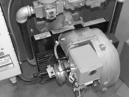
16 Operation Cub 400/ System Component Locations wcghi_gr Ref. Description Ref. Description 1 Control panel 7 Heated fuel filter 2 Burner assembly 8 Fork lift pockets 3 Recirculation damper 9 Blower temperature capillary tube 4 Heater temperature capillary tube 10 Over temperature capillary tube 5 Supply air port 11 Fuel tank 6 Lifting eye 12 Burner exhaust port wcghi_tx000683gb.fm 14
17 Cub 400/ Control Panel Operation a b wcghi_gr Ref Component Function a Operation mode switch 3-position switch which switches power to one of three modes: VENTILATE power to blower only. OFF power to burner is off; power remains to blower until thermostat reads 104 F (40 C) or lower. HEAT power to burner and blower. b Reset switch Resets the system after an over-temperature condition. An over-temperature condition exists at temperatures above 212 F (100 C). Remove cap to access reset button. wcghi_tx000683gb.fm 15
18 Operation Cub 400/ Preliminary Checks Before starting the Cub 400 or Cub 700, check the following: Fuel supply on diesel burning machines. See Fuel Blending Guide. Position of operation mode switch. It must be in the OFF ( 0 ) position. Power supply.each machine must be connected to two (2) separate power supplies adhering to specific requirements. Please see the Technical Data tables in this manaul for the specific power requirements. Note: On diesel burning machines, the fuel heater will begin heating the fuel as soon as power is connected to the machine. Thermostat plug/remote thermostat connection. Either the thermostat plug or the remote thermostat cable must be connected in order for the machine to operate. wcghi_tx000683gb.fm 16
19 Cub 400/ Starting the Machine Operation If using the remote thermostat, place it in the area to be heated. Set it to the desired temperature Turn the operation mode switch to the HEAT position. The burner will start. It will go through a prepurge cycle and then light. As soon the air temperature reaches approximately 104 F (40 C), the blower will start. The burner will continue to fire until the temperature of the space being heated reaches the temperature set by the thermostat. At that time, the burner shuts down but the blower will remain on. wcghi_tx000683gb.fm 17
20 Operation Cub 400/ Shutting Down the Machine Turn the operation mode switch to the OFF ( 0 ) position. The burner will shut down. As soon as the air temperature decreases to below approximately 104 F (40 C), the blower will stop. Electric shock and cutting injury hazard! At temperatures above 104 F (40 C), electric power is available at the supply blower even with the operation mode switch in the OFF position. Always remove all power to the machine before servicing it Once the blower has shut off automatically, disconnect the power supply cord. NOTICE: Do not disconnect the power supply cord until the blower has cooled the heat exchanger and has shut off automatically Disconnect the remote thermostat and re-install the thermostat plug When using NG or LP gas, have a qualified and licensed technician disconnect the gas supply. WARNING wcghi_tx000683gb.fm 18

 or the thermostat plug (a) must be")


21 Cub 400/ Using the Remote Thermostat Operation See Graphic: wcghi_gr In order for the machine to function, the remote thermostat (b) or the thermostat plug (a) must be installed into the control panel. To use the remote thermostat: Plug (c) the remote thermostat into the control panel Set the sensor end within the space to be heated Adjust the temperature setting with dial (d). b a d c wcghi_gr wcghi_tx000683gb.fm 19
22 Operation Cub 400/ Adjusting the Recirculation System See Graphic: wcghi_gr When the machine is positioned within the space (A) to be heated, the recirculation baffle can be used to reduce fuel costs. The open position of the recirculation baffle brings air to the heat exchanger from the space to be heated instead of using cooler, outside air. This practice saves fuel and provides the ability to achieve higher internal building temperatures because the machine does not have to raise the temperature of recirculated (preheated) as far as it does the outside non-recirculated air When the machine is positioned outside of the space (B) to be heated, the recirculation baffle can be used to introduce fresh air into the air supply. A Hot Warm Cool B wcghi_gr wcghi_tx000683gb.fm 20
23 Cub 400/700 Notes: Operation wcghi_tx000683gb.fm 21
24 Operation Cub 400/ Suggested Venting See Graphic: wcghi_gr Suffocation hazard! Exhaust gas from this machine contains carbon monoxide, which is an odorless, colorless, and deadly gas. This machine must be properly vented to reduce the risk of carbon monoxide poisoning. WARNING When installing vents: Adhere to all local and national codes. Consult all appropriate governing bodies or local contractor for venting and fresh air requirements. Place the machine in a manner that avoids excessive vent bends (elbows), and long horizontal runs. Keep air inlets and outlets free from obstruction. Route the venting pipes in a manner that avoids any flammable material. Route the venting pipes in a manner that avoids contact with humans. wcghi_tx000683gb.fm 22
25 Cub 400/700 Operation WARNING wcghi_gr Exhaust gas from this machine CAN KILL YOU IN MINUTES. The exhaust contains carbon monoxide, a deadly poison you can not see or smell. This machine must be properly vented to reduce the risk of carbon monoxide poisoning. The above venting diagram shows suggested venting layouts only. Consult all appropriate governing bodies or local contractor for venting and fresh air requirements. wcghi_tx000683gb.fm 23
26 Operation Cub 400/ Connecting the Main Electric Power Supply WARNING Electric shock hazard. High voltage can cause severe injury or death. Shut down and lock out the main source of electric power before connecting it to the machine. The main electrical power source and mating electrical adapters are provided by the end user. The power source must adhere to the following guidelines: Cub 400 The power supplies must be 115V, 15A (NEMA 5-15) and 230V, 20A (NEMA L6-20). Cub 700 The power supplies must be 115V, 15A (NEMA 5-15) and 230V, 30A (NEMA L6-30). All machines The cord must be no longer than 30 m (100 ft.). The main power source must be connected to the machine at the main control panel. wcghi_tx000683gb.fm 24
27 Cub 400/ Installing the Plenums Operation See Graphic: wcghi_gr Various plenums are available as accessories. Plenum configurations for the Cub 400 include: 3x12 in., 2x16 in., and 1x20 in. Plenum configurations for the Cub 700 include: 3x16 in., and 2x20 in. The plenums (a) are mounted to the front of the machine using four bolts. a wcghi_gr wcghi_tx000683gb.fm 25
28 Operation Cub 400/ Checking the Burner Air Setting See Graphic: wcghi_gr To check burner air setting, carry out the following procedure Shut down the machine and allow it to cool Loosen the two screws (a) that secure the air adjustment plate (b) Rotate the air adjustment plate so that the proper number on the air adjustment plate lines up with the setting indicator (c). See the burner set-up chart Once the air adjustment plate is set, tighten the two screws (a). 4.9 b c a wcghi_gr Note: This procedure must be performed at each new job site. The proper setting depends on environmental conditions at the work site. wcghi_tx000683gb.fm 26
29 Cub 400/ Maintenance Maintenance 4.1 Periodic Maintenance Schedule Check/adjust supply blower belt. Replace oil burner nozzle. Check/adjust oil burner electrodes. Check /adjust oil burner fuel pressure. Replace fuel heater filter. Check gas burner distributor head & mixing plate. Check gas burner ignition electrode. Check gas burner ionization probe. Check gas pressure. Every 600 hours or 6 months Every 1200 hours or yearly wcghi_tx000684gb.fm 27
30 Maintenance Cub 400/ Changing and Adjusting the Supply Blower Belt See Graphic: wcghi_gr To change and adjust the supply blower belt, carry out the following procedure. Replace glazed, worn, or cracked belts. Removal: Electric shock and cutting injury hazard! Disconnect the main power supply to the machine before servicing the supply blower. WARNING Remove the screws that secure the access panel and remove the access panel Loosen the nuts on the four screws (a) that secure the motor plate to the mounting flange Rotate the motor plate to release tension on the belt Roll the belt off of the pulleys. Installation: Roll a new belt onto the pulleys Rotate the motor plate to apply tension to the belt. A properly adjusted belt will have approximately 3/8 1/2 inches (10 13 mm) of deflection at the center of the belt when pressed with moderate pressure Tighten the nuts on the four screws (a) that secure the motor plate to the mounting flange. When tightening the nuts, be sure to keep the motor plate parallel with the blower housing, and the motor pulley parallel to the blower pulley Secure the access panel to the machine. wcghi_tx000684gb.fm 28
 wcghi_gr003887 wcghi_tx000684gb.")
31 Cub 400/700 Maintenance a 3/8 1/2 in. (10 13mm) wcghi_gr wcghi_tx000684gb.fm 29
32 Maintenance Cub 400/ Replacing the Oil Burner Nozzle See Graphic: wcghi_gr To replace the burner nozzle, carry out the following procedure. Removal: Shut down the machine and allow it to cool Remove the burner assembly cover Loosen screw (3) Carefully pull the control box (1) back, then up and away from the burner assembly Remove the two screws (4) that secure the air tube cover plate (5) and remove the air tube cover plate Loosen screw (2), then slide the complete drawer assembly out of the combustion head Loosen screw (6), then remove the nozzle adapter (7) from the drawer assembly Remove the nozzle (8) from the nozzle adapter. Installation: Install the nozzle (8) into the nozzle adapter (7) Install the nozzle adapter into the drawer and secure it with screw (6) Install the drawer assembly into the combustion head and secure it with screw (2) Install the air tube cover plate (5) with two screws (4) Install the control box (1) Tighten screw (3) Install the burner assembly cover. wcghi_tx000684gb.fm 30
33 Cub 400/700 Maintenance wcghi_gr wcghi_tx000684gb.fm 31
34 Maintenance Cub 400/ Checking and Adjusting the Oil Burner Electrodes See Graphic: wcghi_gr To check and adjust the burner electrodes, carry out the following procedure Shut down the machine and allow it to cool Remove the cover from the burner assembly Loosen screw (3) Carefully pull the control box (1) back, then up and away from the burner assembly Remove the two screws (4) that secure the air tube cover plate (5) and remove the air tube cover plate Loosen screw (2), then slide the complete drawer assembly out of the combustion head Loosen the electrodes and adjust them as shown Install the drawer assembly into the combustion head and secure it with screw (2) Install the air tube cover plate (5) with two screws (4) Install the control box (1) Tighten screw (3) Re-install the cover to the burner assembly. wcghi_tx000684gb.fm 32
35 Cub 400/700 Maintenance 5/32 in. (4 mm) 13/64 in. (5 mm) 5/32 3/64 in. (4 5 mm) wcghi_gr wcghi_tx000684gb.fm 33

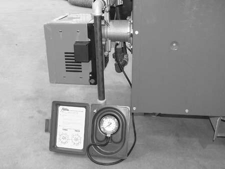
36 Maintenance Cub 400/ Checking the Fuel Pressure See Graphic: wcghi_gr To check fuel pressure, carry out the following procedure Shut down the machine and allow it to cool Remove the bleeder valve (a) from the fuel pump All pump ports are British Parallel thread design. A gauge with like threads must be used, or an appropriate adapter. Insert the gauge or adapter in place of the bleeder valve Start the machine With the burner firing, check the pump pressure. The fuel pump s range is psi ( bar). See burner set-up chart. V RIELLO P a a wcghi_gr wcghi_tx000684gb.fm 34
 is located near")
.")
37 Cub 400/ Changing the Fuel Heater Filter Maintenance See Graphic: wcghi_gr The fuel heater assembly (a) is located near the burner. To replace the fuel heater filter, carry out the following procedure. Removal: Shut down the machine and allow it to cool Remove the screw that secures the cover to the housing Remove the filter (b). Installation: Install the new filter (b) Install the cover. a b wcghi_gr wcghi_tx000684gb.fm 35
38 Maintenance Cub 400/ OIl Burner Adjustments The machine should be operated with standard diesel/fuel oil (OIL) DIESEL. Note: All burners are test fired at Ground Heaters, Inc.'s factory located 600 ft.(180 m) above sea level (asl) using 70/30% blend of #2 diesel with additives (70%) and #1 (K1) diesel (30%) with additives. The use of a high quality combustion analyzer and fuel pressure test gauge is mandatory. All adjustments must be accomplished by a licensed professional and must conform to the requirements of local, state and federal codes and authorities. A qualified technician must recalibrate the burner air and fuel settings to obtain proper combustion at your work site. To ensure proper burner performance and to avoid machine downtime due to heater sooting, burner combustion verification and adjustment must be performed: Before operating at elevations 1,000 ft (305 m) above or below the last adjustment. Before starting at a new job site. After any burner maintenance has been performed. If burner performance is in question for any reason. Fuel Pressure Adjustment: Remove the bleeder valve. Install an adapter with British Parallel threads to accept a psi fuel pressure gauge. Do not use joint compound (pipe dope) on the adapter Turn the operation mode switch to HEAT. The burner will begin a 15- second pre-purge. Monitor the fuel pressure during the pre-purge and make adjustments using the fuel pressure adjusting screw Turn the adjusting screw (located on the side of the fuel pump) clockwise to increase fuel pressure or counterclockwise to decrease fuel pressure until it is stable. Once the fuel pressure is set, proceed with air setting and adjustment. O 2 Content: A Combustion Analyzer, Smoke True Spot Tester and common hand tools will be required for O 2 content sampling Follow the combustion analyzer manufacturer s instructions for prepurge and exhaust sampling. wcghi_tx000684gb.fm 36
39 Cub 400/700 Maintenance Sample the exhaust gas. Exhaust O 2 content must be 3 to 4% for optimum performance and minimum soot production. Several samples should be taken as the heater warms. The final sample should be taken just before the heater reaches 160 F. Smoke Spot Sampling: Follow the smoke spot tester manufacturer s instructions for accurate exhaust sampling Sample the burner exhaust for smoke. Smoke spot production must be 1 or less. Several samples should be taken as the heater warms. The final sample should be taken just before the heater reaches 160 F. Note: Higher O 2 percentage (excess air settings) lowers soot production but raises stack temperature and reduces efficiency. Lower O 2 percentage (inadequate air settings) increases efficiency and lowers stack temperature but may cause soot build-up. A burner optimized for clean and efficient operation will have O 2 levels of 3 to 4% and a smoke spot value of 1 or less Loosen the air damper locking screws enough to provide movement for adjustment Turn the operation mode switch to HEAT. The burner will begin a 15- second pre-purge followed by the ignition sequence Once the burner lights, sample the exhaust as outlined above. Adjust the air damper until combustion parameters fall within the above outlined values Lock the air damper in place by tightening the locking screws. wcghi_tx000684gb.fm 37
40 Maintenance Cub 400/ Fuel Blend Guide Fuel Blend Guide Temperature Range Fuel Blend 15 to 30 F 80% #2 : 20% #1 0 to 15 F 70% #2 : 30% #1 15 to 0 F 50% #2 : 50% #1 below 15 F 30% #2 : 70% #1 wcghi_tx000684gb.fm 38
41 Cub 400/ Oil Burner Set-up Chart Maintenance CUB Actual firing rate ± 5% Nozzle size Pump pressure gph l/h gph psi bar Turbulator setting (head setting) Air damper setting x CUB Actual firing rate ± 5% Nozzle size Pump pressure gph l/h gph psi bar Turbulator setting (head setting) Air damper setting x Gas Burner Set-up Chart Cub 400 Cub 700 NG LP NG LP Air damper setting Combustion head setting Gas manifold pressure (in. wc) wcghi_tx000684gb.fm 39
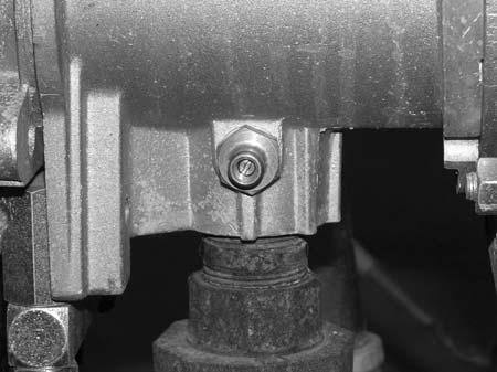
42 Maintenance Cub 400/ Turbulator Setting (Head Setting) To set the turbulator (head), carry out the following procedure Shut down the machine and allow it to cool Remove the burner assembly cover Loosen the nut (a) Turn screw (b) until the index marker (c) is aligned with the 5 0 correct number on the burner 5 0 set up chart. a Retighten the nut (a) Re-install the burner assembly cover. c b wcghi_gr wcghi_tx000684gb.fm 40
43 Cub 400/700 Notes: Maintenance wcghi_tx000684gb.fm 41
44 Maintenance Cub 400/ Checking and Adjusting the Gas Pressure See Graphic: wcghi_gr To check the gas pressure, a manometer will be needed. To check the the gas pressure, carry out the following procedure: Shut down the machine and allow it to cool Remove the large shroud covering the burner assembly Locate the pressure test port (a) Insert a small screwdriver into the pressure test port and back off the needle valve (b) two turns Connect the hose of the manometer (c) to the pressure test port Start the machine With the burner firing, check the pressure reading on the manometer. Adjust the gas pressure at the regulator (d): Remove the cap (e) from the regulator Turn the screw (f) to adjust the pressure Reinstall the cap. Once the gas pressure is set: Shut down the machine Remove the manometer tube from the pressure test port Tighten the needle valve. NOTICE: Do not overtighten the needle valve. Damage to the needle valve will occur. wcghi_tx000684gb.fm 42


45 Cub 400/700 Maintenance a b d c e f wcghi_gr wcghi_tx000684gb.fm 43
46 Maintenance Cub 400/ Checking and Adjusting the Electrode and Ionization Probe See Graphic: wcghi_gr To adjust the electrode and the ionization probe, carry out the following procedure: Remove the combustion head. See section Removing the Combustion Head Clean the head as necessary Adjust the ionization probe (a) so that it is positioned from the mixing plate as shown Adjust the electrode (b) so that it is positioned from the mixing plate as shown. NOTICE: On Cub 400 machines, when adjusting the electrode, keep as much distance between the electrode and the ionization probe as possible. If the electrode is positioned too close to the ionization probe, the amplifier of the control box may be damaged. Cub mm mm a b Cub a a 2 3 wcghi_gr wcghi_tx000684gb.fm 44

47 Cub 400/ Checking Function of Ionization Probe Maintenance See Graphic: wcghi_gr The minimum amount of current necessary for the control module to operate properly is 5 micro Amps (ua). This current is provided by the ionization probe. To check the ionization current, carry out the following procedure: Shut down the machine and allow it to cool Remove the cover from the burner assembly Disconnect the red connector (a) in the wire between terminal 9 and the ionization probe (c) Connect an microammeter (b) in series as shown Start the machine With the burner firing check the meter reading. It must be above 5 ma. a 9 a b + a c wcghi_gr wcghi_tx000684gb.fm 45
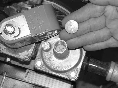
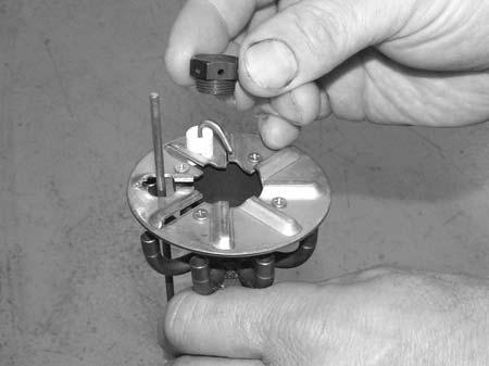
48 Maintenance Cub 400/ Changing Burner Orifice See Graphic: wcghi_gr The burner is set up at the factory to burn natural gas. By changing the burner orifice, the burner can be set up to burn LP gas. Each orifice is stamped with the orifice size. To change the orifice: Shut down the machine and allow it to cool Remove the combustion head (a). See section Removing the Combustion Head Remove the natural gas orifice (b) (2.2 or 3.7) Install the LP gas orifice (c) (1.5 or 2.0) Affix the LP gas label (d) to the burner Re-install the combustion head. Machine natural gas Orifice marking LP Cub Cub wcghi_tx000684gb.fm 46


49 Cub 400/700 Maintenance a b d c wcghi gr wcghi_tx000684gb.fm 47
50 Maintenance Cub 400/ Transporting See Graphic: wcghi_gr Cub 400/700 machines must be transported one of two ways. The machines can be lifted and transported using the fork pockets or by means of an aerial lifting rig. NOTICE: DO NOT route straps or chains over the top of the machine. Failure to comply will damage the machine These machines are NOT designed to be towed with any vehicle Openings on the entire unit should be covered during transport to avoid road debris and clutter All venting external to the machine must be removed prior to transporting Fork pockets on any side of the machine may be used ALWAYS use the lifting point on the top of the machine when using an aerial lifting rig Only qualified riggers should attempt aerial lifting. wcghi_tx000684gb.fm 48
51 Cub 400/ Gas Analyzer Access Hole Maintenance See Graphic: wcghi_gr00393 For analyzing the exhaust gas, drill an access hole as shown. 1-1/2 in. 11/16 in..375 DIA CUB in. Return air blower 1-1/2 in. 3 in..375 DIA 5 in. CUB 700 Return air blower wcghi_gr wcghi_tx000684gb.fm 49
52 Maintenance Cub 400/ List of Abbreviations Amp ampere (unit of electrical current) asl above sea level BTU British Thermal Unit C Celsius (metric unit of temperature) F Fahrenheit (unit of temperature) ft 2 square foot/square feet (measurement of area) ft.lbs. foot pounds (unit of torque) gph gallons per hour (unit of liquid flow) GFI Ground Fault Interrupt(er) (protection device) Hz Hertz (unit of frequency) ID inner diameter in. inch kg kilogram kilo-cal kilo-calorie (1000 calories) (metric unit of heat energy) kpal kilo-pascals (metric unit of pressure) kw kilo-watt (unit of electrical power) lb. pound m meter mm millimeter (1/1000 of a meter) psig pounds per square inch gauge (unit of pressure) VAC Volts, Alternating Current VDC Volts, Direct Current VFD Varible Frequency Drive HTF Heat Transfer Fluid wcghi_tx000684gb.fm 50
53 Cub 400/ Troubleshooting Maintenance Issue Possible Cause Description The burner does not start The remote thermostat or thermostat plug is not inserted correctly. Faulty cable or power supply The over temperature limit has tripped Insert the remote thermostat or thermostat plug. Check cable and power supply Call Ground Heaters for service assistance The burner starts, the flame does not ignite, the unit locks out The burner starts, flame ignites, but the unit locks out No fuel Worn burner nozzle Faulty electrodes Ionization probe faulty Cad cell defective Burner control defective Incorrect fuel pressure Worn burner nozzle Incorrect air adjustment Ionization probe faulty Fill fuel tank Replace burner nozzle Replace electrodes Clean, adjust, or replace ionization probe Call Ground Heaters for service assistance Increase fuel pressure Replace burner nozzle Readjust air supply Clean, adjust, or replace ionization probe Cad cell defective Burner control defective Combustion is poor or noisy Lack of fresh air to burner Excessive blower noise Defective motor bearings Mounting base not secure Misaligned pulleys Damaged wheel Fan inoperative Open circuit breaker Loose or disconnected wiring Defective motor Broken belt(s) Call Ground Heaters for service assistance Ensure there is an adequate air supply Call Ground Heaters for service assistance Replace motor bearings Tighten mounting hardware Correct alignment Replace wheel Reset circuit breaker Check wiring and repair as needed Replace motor Replace belt(s) wcghi_tx000684gb.fm 51
54 Maintenance Cub 400/700 Motor overheating Belt slippage Over or under voltage Adjust belt tension Check power supply wcghi_tx000684gb.fm 52
55 Cub 400/ Wiring Diagram Maintenance TR A1 3 PT 2 STB LIM FAN C C TH SM 95 BRN BLK WHT WHT e i MR IR UT1 U1/T4 WHT BLK M WHT BLK WHT BLK N L 115 V 60 Hz L1 L2 230 V 60 Hz BRN BLU FR BLK 3 WHT 2 PB BR Burner IR Switch M Fan motor MR Terminal board PT Thermostat socket SM Thermal protector TH Thermostat FR Heated filter PB Burner socket ( 115V ) REVERSAL OF ROTATION CAPACITOR CAPACITOR W2 U2 V2 W2 U2 V2 RED WHT RED WHT WHT RED WHT RED U1 V1 W1 U1 V1 W1 SINGLE-PHASE-MOTOR LINE SINGLE-PHASE-MOTOR LINE wcghi_gr wcghi_tx000684gb.fm 53
56 Maintenance Cub 400/700 wcghi_tx000684gb.fm 54
57 Cub 400/ Technical Data Technical Data 5.1 Cub 400 Technical Data Item Number: Cub 400 Dimensions LxWxH in (cm) 94 x 34 x 52 (241x86x132) 95 x 34 x 75 (241x86x191) 95 x 34 x 52 (241x86x132) Weight with fuel without fuel lbs. (kg) (265) 1373 (623) 898 (407) (265) Gross input BTU/hr 380, , ,000 Net output BTU/hr 304, , ,000 Efficiency % Air output volume cfm Static pressure in. wc Power requirements VAC, Amps, Hz; Plug 115, 15, 60; NEMA 5-15 and 230, 20, 60; NEMA L , 15, 60; NEMA 5-15 and 230, 20, 60; NEMA L , 15, 60; NEMA 5-15 and 230, 20, 60; NEMA L6-20 Blower motor VAC, Amp 230, , , 10 Vent pipe diameter (nominal) in. (cm) 8 (20) 8 (20) 8 (20) Burner nozzle (solid spray) gph , , 60 Fuel pressure psig (bar) (12.7) 184 (12.7) Fuel consumption gph (l/h) (10.26) 2.71 (10.26) Air shutter (factory setting) Fuel capacity gal. (l) (254) --- Hours of operation per tank * --- wcghi_td000198gb.fm 55
58 Technical Data Cub 400/700 NG LP Orifice Supply fuel pressure (max.) in. wc 10.0 Manifold pressure (operating) in. wc Fuel consumption ft 3 /hr (m 3 /hr) 380 (10.76) --- gph (l/hr) (15.7) * Longer run time are achieved when using the machine indoors wcghi_td000198gb.fm 56
59 Cub 400/700 Technical Data 5.2 Cub 700 Technical Data Item Number: Cub 700 Dimensions LxWxH in (cm) 117x45x67 (297x114x170) 119x45x88 (302x114x224) 119x45x67 (302x114x170) Weight: with fuel without fuel lbs. (kg) (436.8) (1138) 1494 (677) (437) Gross input BTU/hr 720, , ,000 Net output BTU/hr 576, , ,000 Efficiency % Air output volume cfm Static pressure in. wc Power requirements VAC, Amps, Hz; Plug 115, 15, 60; NEMA 5-15 and 230, 30, 60; NEMA L , 15, 60; NEMA 5-15 and 230, 30, 60; NEMA L , 15, 60; NEMA 5-15 and 230, 30, 60; NEMA L6-30 Blower motor VAC, Amp 230, , , 13 Vent pipe diameter (nominal) in. (cm) 10 (25.4) 10 (25.4) 10 (25.4) Burner nozzle (soilid spray) gph Fuel pressure psig (bar) (11.4) 165 (11.4) Fuel consumption gph (lph) (19.4) 5.13 (19.4) Air shutter (factory setting) Fuel capacity gal. (l) (549) --- Hours of operation per tank 28.26* --- NG LP Orifice Supply fuel pressure (max) in. wc 10 Manifold pressure (operating) in. wc Fuel consumption ft 3 /hr (m 3 /hr) gph (l/hr) * Longer run time are achieved when using the machine indoors wcghi_td000198gb.fm 57
60 Technical Data Cub 400/700 wcghi_td000198gb.fm 58
Operator s Manual. Hydronic Air Heater. Arctic Bear XHD-NS en /
 Operator s Manual Hydronic Air Heater Arctic Bear XHD-NS 0 1 7 8 3 9 1 E N 0178391en / 001 1107 Arctic Bear XHD Foreword Foreword Machines covered by this manual This manual covers machines with the following
HI 110D / HI 110HD D HI 200D / HI 200HD D HI 300D / HI 300HD D
 Operator s Manual Indirect-Fired Air Heaters HI 110D / HI 110HD D HI 200D / HI 200HD D HI 300D / HI 300HD D 0192822 001 1110 0 1 9 2 8 2 2 Copyright notice Copyright 2010 by Wacker Neuson Corporation.
HI 110D / HI 110HD D HI 200D / HI 200HD D HI 300D / HI 300HD D
 Operator s Manual Indirect-Fired Air Heaters HI 110D / HI 110HD D HI 200D / HI 200HD D HI 300D / HI 300HD D EN 5000192822 03 1211 5 0 0 0 1 9 2 8 2 2 Copyright notice Copyright 2011 by Wacker Neuson Production
OPERATING INSTRUCTIONS MANUAL (Please retain for future reference) FVO-200 INDIRECT FIRED SPACE HEATERS
 FVO-200 INDIRECT FIRED SPACE HEATERS") OPERATING INSTRUCTIONS MANUAL (Please retain for future reference) For FVO-200 INDIRECT FIRED SPACE HEATERS CERTIFIED FOR USE IN CANADA AND U.S.A. As per CSA B140.8 Portable Oil Fired Heaters / CSA B140.02003
OPERATING INSTRUCTIONS MANUAL (Please retain for future reference) For FVO-200 INDIRECT FIRED SPACE HEATERS CERTIFIED FOR USE IN CANADA AND U.S.A. As per CSA B140.8 Portable Oil Fired Heaters / CSA B140.02003
HI 400 HD D HI 400 HD G
 Operator s Manual Indirect-Fired Air Heaters HI 400 HD D HI 400 HD G EN 5000192824 03 1211 5 0 0 0 1 9 2 8 2 4 Copyright notice Copyright 2011 by Wacker Neuson Production Americas LLC All rights, including
Repair Manual Indirect-Fired Air Heater Cub 200 Cub 300
 Repair Manual Indirect-Fired Air Heater Cub 200 Cub 300 0179422en 001 1009 0 1 7 9 4 2 2 E N Copyright notice Copyright 2009 by Wacker Neuson Corporation. All rights, including copying and distribution
en Hydronic Surface Heater E 1100 REPAIR MANUAL
 0176742en 002 0209 Hydronic Surface Heater REPAIR MANUAL 0 1 7 6 7 4 2 E N Foreword Foreword Machines covered by this manual Machine Item Number 0620172 0620244 Machine documentation Keep a copy of the
OPERATING INSTRUCTIONS MANUAL (Please retain for future reference) FVO-400 INDIRECT FIRED SPACE HEATERS
 FVO-400 INDIRECT FIRED SPACE HEATERS") OPERATING INSTRUCTIONS MANUAL (Please retain for future reference) For FVO-400 INDIRECT FIRED SPACE HEATERS CERTIFIED FOR USE IN CANADA AND U.S.A. As per CSA B140.8 Portable Oil Fired Heaters / CSA B140.02003
OPERATING INSTRUCTIONS MANUAL (Please retain for future reference) For FVO-400 INDIRECT FIRED SPACE HEATERS CERTIFIED FOR USE IN CANADA AND U.S.A. As per CSA B140.8 Portable Oil Fired Heaters / CSA B140.02003
OPERATING INSTRUCTIONS MANUAL (Please retain for future reference) For FVO-400TRLT INDIRECT FIRED HEATER TRAILER
 For FVO-400TRLT INDIRECT FIRED HEATER TRAILER") OPERATING INSTRUCTIONS MANUAL (Please retain for future reference) For FVO-400TRLT INDIRECT FIRED HEATER TRAILER CERTIFIED FOR USE IN CANADA AND U.S.A. As per CSA B140.8 Portable Oil Fired Heaters / CSA
OPERATING INSTRUCTIONS MANUAL (Please retain for future reference) For FVO-400TRLT INDIRECT FIRED HEATER TRAILER CERTIFIED FOR USE IN CANADA AND U.S.A. As per CSA B140.8 Portable Oil Fired Heaters / CSA
OPERATING INSTRUCTIONS MANUAL (Please retain for future reference) FVN/P-400 INDIRECT FIRED SPACE HEATERS
 FVN/P-400 INDIRECT FIRED SPACE HEATERS") OPERATING INSTRUCTIONS MANUAL (Please retain for future reference) For FVN/P-400 INDIRECT FIRED SPACE HEATERS CERTIFIED FOR USE IN CANADA AND U.S.A. As per Standard ANSI Z83.7/CSA 21.4 2000 Gas Fired Construction
OPERATING INSTRUCTIONS MANUAL (Please retain for future reference) For FVN/P-400 INDIRECT FIRED SPACE HEATERS CERTIFIED FOR USE IN CANADA AND U.S.A. As per Standard ANSI Z83.7/CSA 21.4 2000 Gas Fired Construction
Multi-Function Cooktop
 INSTALLATION GUIDE Multi-Function Cooktop Contents Wolf Multi-Function Cooktop.................... 3 Multi-Function Cooktop Specifications............ 4 Multi-Function Cooktop Installation...............
INSTALLATION GUIDE Dual Fuel Ranges
 INSTALLATION GUIDE Dual Fuel Ranges Contents Wolf Dual Fuel Ranges......................... 3 Safety Instructions............................ 4 Dual Fuel Range Specifications.................. 5 Dual Fuel
INTRODUCTION THIS MANUAL INCLUDES IMPORTANT SAFETY INFORMATION
 INSTALLATION AND OPERATING INSTRUCTIONS FOR THE HARDY Fuel Oil Furnace Models D-140 & D-350 HARDY MANUFACTURING COMPANY, INC. 12345 ROAD 505 PHILADELPHIA, MS 39350 PHONE: (601) 656-5866 FAX: (601) 656-4559
1. GENERAL SAFETY RULES
 ID180 & ID290 Indirect-Fired Diesel/Oil Construction Heaters Sure Flame Products Lethbridge, Alberta, Canada Telephone: (403)328-5353 Fax: (403)328-9956 www.sureflame.ca July 12, 2006 Service and Maintenance
OPERATING INSTRUCTIONS MANUAL (Please retain for future reference) FVO-200 INDIRECT FIRED SPACE HEATERS
 FVO-200 INDIRECT FIRED SPACE HEATERS") OPERATING INSTRUCTIONS MANUAL (Please retain for future reference) For FVO-200 INDIRECT FIRED SPACE HEATERS CERTIFIED FOR USE IN CANADA AND U.S.A. As per CSA B140.8 Portable Oil Fired Heaters / CSA B140.02003
OPERATING INSTRUCTIONS MANUAL (Please retain for future reference) For FVO-200 INDIRECT FIRED SPACE HEATERS CERTIFIED FOR USE IN CANADA AND U.S.A. As per CSA B140.8 Portable Oil Fired Heaters / CSA B140.02003
OPERATING INSTRUCTIONS MANUAL (Please retain for future reference) FVN/P-400 INDIRECT FIRED SPACE HEATERS
 FVN/P-400 INDIRECT FIRED SPACE HEATERS") OPERATING INSTRUCTIONS MANUAL (Please retain for future reference) For FVN/P-400 INDIRECT FIRED SPACE HEATERS CERTIFIED FOR USE IN CANADA AND U.S.A. As per Standard ANSI Z83.7/CSA 21.4 2000 Gas Fired Construction
OPERATING INSTRUCTIONS MANUAL (Please retain for future reference) For FVN/P-400 INDIRECT FIRED SPACE HEATERS CERTIFIED FOR USE IN CANADA AND U.S.A. As per Standard ANSI Z83.7/CSA 21.4 2000 Gas Fired Construction
OPERATING INSTRUCTIONS MANUAL (Please retain for future reference) For FVO-1000TR INDIRECT FIRED HEATER TRAILER
 For FVO-1000TR INDIRECT FIRED HEATER TRAILER") OPERATING INSTRUCTIONS MANUAL (Please retain for future reference) For FVO-1000TR INDIRECT FIRED HEATER TRAILER CERTIFIED FOR USE IN CANADA AND U.S.A. As per CSA B140.8 Portable Oil Fired Heaters / CSA
OPERATING INSTRUCTIONS MANUAL (Please retain for future reference) For FVO-1000TR INDIRECT FIRED HEATER TRAILER CERTIFIED FOR USE IN CANADA AND U.S.A. As per CSA B140.8 Portable Oil Fired Heaters / CSA
Bosch 80% AFUE Gas Furnace BGS80 Model
 Bosch 80% AFUE Gas Furnace BGS80 Model 4-Way Multipoise Category I Fan-Assisted Furnace User's Information Manual 3124627 2 Bosch 80% AFUE Gas Furnace User's Information Manual Data subject to change 06.2018
B.C.S. Shop Heaters 26, 30 & 36 (36 shown)
") BIOMASS COMBUSTION SYSTEMS, INC. 67 MILLBROOK ST., SUITE 502 WORCESTER, MA 01606 508-798-5970 - FAX 508-798-5971 B.C.S. Shop Heaters 26, 30 & 36 (36 shown) INSTALLATION MANUAL HAND FIRED SYSTEMS 8-09 Biomass
BIOMASS COMBUSTION SYSTEMS, INC. 67 MILLBROOK ST., SUITE 502 WORCESTER, MA 01606 508-798-5970 - FAX 508-798-5971 B.C.S. Shop Heaters 26, 30 & 36 (36 shown) INSTALLATION MANUAL HAND FIRED SYSTEMS 8-09 Biomass
HT650 TM FAN DRIVE SERVICE INSTRUCTIONS
 HT650 TM FAN DRIVE SERVICE INSTRUCTIONS When unpacking your product, remove all components and inspect them to ensure that no damage occurred during shipping. If any components are missing or damaged,
VF/VG700 Jumbo. Construction Heater. Installation and Maintenance Manual
 342 N. Co. Rd. 400 East Valparaiso, IN 46383 888-432-8924 Fax 219-462-7985 www.heatwagon.com Installation and Maintenance Manual Please retain this manual for future reference. VF/VG700 Jumbo Construction
Drying Tumblers. Troubleshooting. 120 Pound Capacity 170 Pound Capacity. Refer to Page 5 for Model Numbers. Part No August 2007
 HIGH LOAD READY MEDIUM TEMPERATURE LOW LOW AIR FLOW NON REV REV PUSH TO START 10 5 15 0 50 40 60 0 30 10 20 Drying Tumblers 120 Pound Capacity 170 Pound Capacity Page 5 for Model Numbers Troubleshooting
P.O. Box , Dallas, TX USER'S INFORMATION MANUAL Single-Stage Warm Air Gas Furnaces
 P.O. Box 799900, Dallas, TX 75379-9900 USER'S INFORMATION MANUAL Single-Stage Warm Air Gas Furnaces This is a safety alert symbol and should never be ignored. When you see this symbol on labels or in manuals,
DESIGN CLASS FUNCTION
 PROFESSIONAL QUALITY COOKING EQUIPMENT INSTALLATION MANUAL FOR PERFORMER SLIDE-IN COOK TOPS MODEL NUMBERS: AROBSCT-424, AROBSCT-242GD, AROBSCT-24X2GR, AROBSCT-430, AROBSCT-636, AROBSCT-436GD, AROBSCT-436GR,
OPERATING INSTRUCTIONS MANUAL (Please retain for future reference) FVN/P-400 INDIRECT FIRED SPACE HEATERS
 FVN/P-400 INDIRECT FIRED SPACE HEATERS") OPERATING INSTRUCTIONS MANUAL (Please retain for future reference) For FVN/P-400 INDIRECT FIRED SPACE HEATERS CERTIFIED FOR USE IN CANADA AND U.S.A. As per Standard ANSI Z83.7/CSA 21.4 2000 Gas Fired Construction
OPERATING INSTRUCTIONS MANUAL (Please retain for future reference) For FVN/P-400 INDIRECT FIRED SPACE HEATERS CERTIFIED FOR USE IN CANADA AND U.S.A. As per Standard ANSI Z83.7/CSA 21.4 2000 Gas Fired Construction
OPERATING INSTRUCTIONS MANUAL (Please retain for future reference) F-400T DUAL FUEL CONSTRUCTION HEATER
 F-400T DUAL FUEL CONSTRUCTION HEATER") OPERATING INSTRUCTIONS MANUAL (Please retain for future reference) For F-400T DUAL FUEL CONSTRUCTION HEATER CERTIFIED FOR USE IN CANADA AND U.S.A. As per Standard ANSI Z83.7 2000/ CSA 2.14 2000 Gas Fired
OPERATING INSTRUCTIONS MANUAL (Please retain for future reference) For F-400T DUAL FUEL CONSTRUCTION HEATER CERTIFIED FOR USE IN CANADA AND U.S.A. As per Standard ANSI Z83.7 2000/ CSA 2.14 2000 Gas Fired
OPERATING INSTRUCTIONS MANUAL (Please retain for future reference) F-1500T DUAL FUEL CONSTRUCTION HEATER
 F-1500T DUAL FUEL CONSTRUCTION HEATER") OPERATING INSTRUCTIONS MANUAL (Please retain for future reference) For F-1500T DUAL FUEL CONSTRUCTION HEATER CERTIFIED FOR USE IN CANADA AND U.S.A. As per Standard ANSI Z83.7 2000/ CSA 2.14 2000 Gas Fired
OPERATING INSTRUCTIONS MANUAL (Please retain for future reference) For F-1500T DUAL FUEL CONSTRUCTION HEATER CERTIFIED FOR USE IN CANADA AND U.S.A. As per Standard ANSI Z83.7 2000/ CSA 2.14 2000 Gas Fired
PS /2 Inch Angle Grinder Assembly & Operating Instructions READ ALL INSTRUCTIONS AND WARNINGS BEFORE USING THIS PRODUCT.
 PS07214 4 1/2 Inch Angle Grinder Assembly & Operating Instructions READ ALL INSTRUCTIONS AND WARNINGS BEFORE USING THIS PRODUCT. This manual provides important information on proper operation & maintenance.
Single stage operation oil burner
 Installation & Operating Manual Single stage operation oil burner WARNING NON-RETROFIT APPLICATIONS If this burner is being installed in a packaged unit (ie. burner comes with a boiler or furnace), follow
Installation & Service Instructions for Jackson & Church Flexaire Packaged Furnaces SDF-125 thru SDF-400 Gas Firing
 Installation & Service Instructions for Jackson & Church Flexaire Packaged Furnaces SDF-125 thru SDF-400 Gas Firing Important: To protect the unit and avoid damage to the heat exchanger, the blower speed
PWASH Gallon Parts Washer Assembly & Operating Instructions
 PWASH20 20 Gallon Parts Washer Assembly & Operating Instructions READ ALL INSTRUCTIONS AND WARNINGS BEFORE USING THIS PRODUCT. SAVE THESE INSTRUCTIONS FOR FUTURE REFERENCE. This manual provides important
OPERATING INSTRUCTIONS MANUAL (Please retain for future reference) F-1000T DUAL FUEL CONSTRUCTION HEATER
 F-1000T DUAL FUEL CONSTRUCTION HEATER") OPERATING INSTRUCTIONS MANUAL (Please retain for future reference) For F-1000T DUAL FUEL CONSTRUCTION HEATER CERTIFIED FOR USE IN CANADA AND U.S.A. As per Standard ANSI Z83.7 2000/ CSA 2.14 2000 Gas Fired
OPERATING INSTRUCTIONS MANUAL (Please retain for future reference) For F-1000T DUAL FUEL CONSTRUCTION HEATER CERTIFIED FOR USE IN CANADA AND U.S.A. As per Standard ANSI Z83.7 2000/ CSA 2.14 2000 Gas Fired
Columbia Boiler Company
 EMG Series Boilers Available in Natural Gas & Propane Rev 12012 Columbia Boiler Company PO Box 1070 Pottstown, PA 19464 Tel (610) 473-8457 Fax (610) 367-6800 Website www.columbiaboiler.com Email cbcsales@ptd.net
Internet Version for Reference Only INDUCED DRAFT COMMERCIAL WATER HEATERS SUPPLEMENT INSTRUCTIONS TO PART #
 INDUCED DRAFT COMMERCIAL WATER HEATERS SUPPLEMENT INSTRUCTIONS TO PART #238-39387-00 THIS INSTRUCTION SUPPLEMENT IS ONLY INTENDED TO GIVE INSTALLATION INSTRUCTIONS AND INFORMATION RELATED TO THE INDUCED
USER S INFORMATION MANUAL
 2017 Lennox Industries Inc. Dallas, Texas, USA 506737-01 04/2017 Supersedes 03/2017 USER S INFORMATION MANUAL EL195UHE SERIES GAS FURNACE Improper installation, adjustment, alteration, service or maintenance
OPERATING INSTRUCTIONS MANUAL (Please retain for future reference) FVO-400 INDIRECT FIRED SPACE HEATERS
 FVO-400 INDIRECT FIRED SPACE HEATERS") OPERATING INSTRUCTIONS MANUAL (Please retain for future reference) For FVO-400 INDIRECT FIRED SPACE HEATERS CERTIFIED FOR USE IN CANADA AND U.S.A. As per CSA B140.8 Portable Oil Fired Heaters / CSA B140.02003
OPERATING INSTRUCTIONS MANUAL (Please retain for future reference) For FVO-400 INDIRECT FIRED SPACE HEATERS CERTIFIED FOR USE IN CANADA AND U.S.A. As per CSA B140.8 Portable Oil Fired Heaters / CSA B140.02003
QHT Manual for: SU-2A Gas Burner
 1 QHT Manual for: SU-2A Gas Burner 50,000 BTU/H to 250,000 BTU/H The burner shall be used only with NATURAL GAS or LP GAS. Warning: If the following instructions are not followed exactly, a fire or explosion
SERVICE MANUAL. Bradford White ElectriFLEX HD (Heavy Duty) Commercial Electric Water Heater CEHD SERIES Immersion Thermostat Models
 Commercial Electric Water Heater CEHD SERIES Immersion Thermostat Models") Bradford White ElectriFLEX HD (Heavy Duty) Commercial Electric Water Heater CEHD SERIES Immersion Thermostat Models SERVICE MANUAL Troubleshooting Guide and Instructions for Service (To be performed ONLY
Bradford White ElectriFLEX HD (Heavy Duty) Commercial Electric Water Heater CEHD SERIES Immersion Thermostat Models SERVICE MANUAL Troubleshooting Guide and Instructions for Service (To be performed ONLY
ML180UH SERIES GAS FURNACE WARNING WARNING
 2017 Lennox Industries Inc. Dallas, Texas, USA 506525-01 04/2017 Supersedes 10/2015 ML180UH SERIES GAS FURNACE Improper installation, adjustment, alteration, service or maintenance can cause property damage,
Installation Instructions T 9822 Gas Dryer. en - US, CA. To prevent accidents
 Installation Instructions T 9822 Gas Dryer To prevent accidents en - US, CA and appliance damage read these instructions before installation or use. M.-Nr. 07 431 110 2 WARNING For your safety the information
OPERATING INSTRUCTIONS MANUAL (Please retain for future reference) FVN/P-400 INDIRECT FIRED SPACE HEATERS
 FVN/P-400 INDIRECT FIRED SPACE HEATERS") OPERATING INSTRUCTIONS MANUAL (Please retain for future reference) For FVN/P-400 INDIRECT FIRED SPACE HEATERS CERTIFIED FOR USE IN CANADA AND U.S.A. As per Standard ANSI Z83.7/CSA 21.4 2000 Gas Fired Construction
OPERATING INSTRUCTIONS MANUAL (Please retain for future reference) For FVN/P-400 INDIRECT FIRED SPACE HEATERS CERTIFIED FOR USE IN CANADA AND U.S.A. As per Standard ANSI Z83.7/CSA 21.4 2000 Gas Fired Construction
BG6UL. 6 Inch Bench Grinder Assembly & Operating Instructions
 BG6UL 6 Inch Bench Grinder Assembly & Operating Instructions READ ALL INSTRUCTIONS AND WARNINGS BEFORE USING THIS PRODUCT. SAVE THESE INSTRUCTIONS FOR FUTURE REFERENCE. This manual provides important information
V SERIES HDR GAS RANGES
 SERVICE MANUAL ONE POWERFUL PACKAGE V SERIES HDR GAS RANGES TOPS Open Top Hot Top Griddle Top Work Surface BASES Standard Oven Convection Oven Cabinet Base - NOTICE - This manual is prepared for use by
WARNING FIRE OR EXPLOSION HAZARD.
 2017 Lennox Industries Inc. Dallas, Texas, USA 506698-01 04/2017 Supersedes 10/2015 SL280DFV SERIES GAS FURNACE Improper installation, adjustment, alteration, service or maintenance can cause property
WARNING FIRE OR EXPLOSION HAZARD.
 2017 Lennox Industries Inc. Dallas, Texas, USA 506897-01 04/2017 Supersedes 10/2015 EL280DF SERIES GAS FURNACE Improper installation, adjustment, alteration, service or maintenance can cause property damage,
EL296UHV SERIES GAS FURNACE WARNING WARNING
 2011 Lennox Industries Inc. Dallas, Texas, USA 506769 01 08/2012 Supersedes 10/2011 EL296UHV SERIES GAS FURNACE Improper installation, adjustment, alteration, service or maintenance can cause property
DIESEL/PARAFFIN HEATERS
 DIESEL/PARAFFIN HEATERS MODEL NO: XR80, XR110, XR160, XR210 PART NO: 6931004, 6931006, 6931008, 6931012 OPERATION & MAINTENANCE INSTRUCTIONS LS0814 INTRODUCTION Thank you for purchasing this CLARKE product.
EL195UHE SERIES GAS FURNACE WARNING WARNING
 2012 Lennox Industries Inc. Dallas, Texas, USA 506737-01 12/2012 Supersedes 06/2011 EL195UHE SERIES GAS FURNACE Improper installation, adjustment, alteration, service or maintenance can cause property
Model No: Little Devil II (inc ss)
") GAS HEATER Model No: Little Devil II (inc ss) PART NO: 6926020, 6926025 (SS) OPERATION & MAINTENANCE INSTRUCTIONS LS1213 INTRODUCTION Thank you for purchasing this CLARKE Gas Heater. Before attempting
GAS HEATER Model No: Little Devil II (inc ss) PART NO: 6926020, 6926025 (SS) OPERATION & MAINTENANCE INSTRUCTIONS LS1213 INTRODUCTION Thank you for purchasing this CLARKE Gas Heater. Before attempting
INSTALLATION AND OPERATION MANUAL FOR 2 STAGE RIELLO BURNER ADDENDUM TO ( Mo 437 manual )
") INSTALLATION AND OPERATION MANUAL FOR 2 STAGE RIELLO BURNER ADDENDUM TO ( Mo 437 manual ) FOR USE WITH MODEL: OH6FX072DV4 PLEASE READ THESE INSTRUCTIONS PRIOR TO INSTALLATION, INITIAL FIRING, AND BEFORE
INSTALLATION AND OPERATION MANUAL FOR 2 STAGE RIELLO BURNER ADDENDUM TO ( Mo 437 manual ) FOR USE WITH MODEL: OH6FX072DV4 PLEASE READ THESE INSTRUCTIONS PRIOR TO INSTALLATION, INITIAL FIRING, AND BEFORE
CLIMATE CONTROL PRODUCT GUIDE
 CLIMATE CONTROL PRODUCT GUIDE 0985822 Climate Control Product Guide 3/08-25M CURE THAW PREVENT FROST AIR HEAT DRY TABLE OF CONTENTS 2 3 GROUND HEATERS HEATING AND DRYING Ground Heaters is a brand of climate
THC- 355DF (Dual Fuel)
") OPERATING INSTRUCTIONS MANUAL THC- 355DF (Dual Fuel) INDUSTRIAL / COMMERCIAL DIRECTIONAL SPACE HEATER (OPERATOR MUST RETAIN FOR FUTURE REFERENCES) Certified to / Certifié à ANSI std Z83.7 2000 Suitable
OPERATING INSTRUCTIONS MANUAL THC- 355DF (Dual Fuel) INDUSTRIAL / COMMERCIAL DIRECTIONAL SPACE HEATER (OPERATOR MUST RETAIN FOR FUTURE REFERENCES) Certified to / Certifié à ANSI std Z83.7 2000 Suitable
SAFE DRINKING WATER AND TOXIC ENFORCEMENT ACT
 Installation instructions for your new Spacemaker Laundry WSM2780 Gas Before you begin Read these instructions completely and carefully. IMPORTANT OBSERVE ALL GOVERNING CODES AND ORDINANCES. Note to Installer
RSIF power venter USA CAN READ AND SAVE THESE INSTRUCTIONS! Installation and operation manual. Product information Chapters 1 + 2
 3002239 RSIF 2014-04-04 Installation and operation manual RSIF power venter READ AND SAVE THESE INSTRUCTIONS! Product information Chapters 1 + 2 Mechanical installation Chapter 3 Electrical installation
EL195UH SERIES GAS FURNACE WARNING
 2010 Lennox Industries Inc. Dallas, Texas, USA 506597 01 11/2010 EL195UH SERIES GAS FURNACE Litho U.S.A. FIRE OR EXPLOSION HAZARD. Failure to follow safety warnings exactly could result in serious injury,
EL195DFE SERIES GAS FURNACE WARNING
 2011 Lennox Industries Inc. Dallas, Texas, USA 506739 01 06/2011 EL195DFE SERIES GAS FURNACE Litho U.S.A. FIRE OR EXPLOSION HAZARD. Failure to follow safety warnings exactly could result in serious injury,
S150 S300 CONSTRUCTION HEATERS. Rev: August 15, 2008 SERVICE AND MAINTENANCE MANUAL No PLEASE RETAIN FOR FUTURE REFERENCE PRODUCTS
 S150 & S300 CONSTRUCTION HEATERS Rev: 2.7.2 August 15, 2008 SERVICE AND MAINTENANCE MANUAL No. 934-6637 PLEASE RETAIN FOR FUTURE REFERENCE PRODUCTS A DIVISION OF HAUL-ALL EQUIPMENT LTD. 4115-18 Avenue
Indirect gas-fired air heater
 Indirect gas-fired air heater SERIES HD INSTALLATION AND SERVICE MANUAL MANUFACTURED BY : BROTHERS LIMITED WARNING Improper installation, modification, adjustment or maintenance may cause damage, injury
INSTALLATION & OPERATING INSTRUCTIONS FOR CEILING MOUNT AIR HANDLERS AC SERIES
 C US INSTALLATION & OPERATING INSTRUCTIONS FOR CEILING MOUNT AIR HANDLERS AC SERIES Made in the USA by: Goodman Manufacturing Company, L.P. I0-240B 2550 North Loop West, Suite 400, Houston, TX 77092 www.goodmanmfg.com
PARAFFIN/DIESEL HEATER
 PARAFFIN/DIESEL HEATER MODEL NO: XR60 PART NO: 6931002 OPERATION & MAINTENANCE INSTRUCTIONS LS0813 INTRODUCTION Thank you for purchasing this CLARKE product. Before attempting to use this product, please
LATTNER BOILER COMPANY 9.5 HP Low-NOx Installation and Start-Up Checklist for Dry Cleaners
 1 1. General Installation Information (to be completed by technician) Date installed: Location (city & state): Cleaner s name: National Board number (boiler): Installed by (company): Installed by (technician):
Service Manual For model N260 - a 2.4 cu. ft., 2-way refrigerator. For model N a 2.4 cu. ft., 3-way refrigerator.
 Service Manual For model N260 - a 2.4 cu. ft., 2-way refrigerator. For model N260.3 - a 2.4 cu. ft., 3-way refrigerator. NORCOLD, Inc. P.O. Box 4248 Sidney, OH 45365-4248 Part No. 619260A (4-98) Table
Using it in an enclosed space can kill you.
 38 X 56 GAS FIRE PIT - OWNER S MANUAL Carlisle Chat Fire Table Base Model # 00GBC7 (6877B) Fits 6877A Carlisle Chat Fire Table Top For Propane and *Natural Gas (*See Page 7) Certified to CSA International
POWER VENTER SYSTEM. Model: PVO-300, PVO-600
 POWER VENTER SYSTEM Model: PVO-300, PVO-600 Included is one ETL and cetl listed Power Venter to be used primarily with a single 120VAC controlled oil fired furnace, boiler, or water heater. The PVO may
BG8SS. 8 Inch Slow Speed Bench Grinder with LED Lights Assembly & Operating Instructions
 BG8SS 8 Inch Slow Speed Bench Grinder with LED Lights Assembly & Operating Instructions READ ALL INSTRUCTIONS AND WARNINGS BEFORE USING THIS PRODUCT. SAVE THESE INSTRUCTIONS FOR FUTURE REFERENCE. This
SLP98UH SERIES VARIABLE CAPACITY GAS FURNACE WARNING WARNING
 2015 Lennox Industries Inc. Dallas, Texas, USA 506443-01 01/2015 Supersedes 08/2012 SLP98UH SERIES VARIABLE CAPACITY GAS FURNACE Improper installation, adjustment, alteration, service or maintenance can
INSTALLATION, OPERATION, AND MAINTENANCE MANUAL
 INSTALLATION, OPERATION, AND MAINTENANCE MANUAL TUBE AXIAL FANS BTA, WTA, HTA, DDA The purpose of this manual is to aid in the proper installation and operation of the fans. These instructions are intended
Please read this manual completely before attempting to install, operate or service this equipment.
 Service Manual POWER OVEN OFF COOL DOWN COOK LIGHT OFF OVEN READY TEMPERATURE GAS CONVECTION OVEN TIME GAS SHUTOFF ON OFF MODELS 6/13 THE OVEN E SERIES Please read this manual completely before attempting
G61MPV SERIES GAS FURNACE WARNING
 2003 Lennox Industries Inc. Dallas, Texas, USA 504,809M 03/2009 Supersedes 06/2003 G61MPV SERIES GAS FURNACE Litho U.S.A. FIRE OR EXPLOSION HAZARD. Failure to follow safety warnings exactly could result
KEROSENE FORCED AIR HEATER
 KEROSENE FORCED AIR HEATER operation manual HK125RW HK300RW 2 table of contents Safety 6 Safety Rules 7 Safety Warnings Specifications 12 Specifications 13 Wiring Diagram Pre-Operation 14 General Instructions
BESF Box Ventilator USA CAN. Product Information. Mechanical Installation. ... Chapter 3. Electrical Installation. ... Chapter 4
 Installation & Operating Manual BESF Box Ventilator USA CAN Product Information... Chapter 1 + 2 Mechanical Installation... Chapter 3 Electrical Installation... Chapter 4 Start Up and Configuration...
SERVICE AND INSTALLATION MANUAL MODELS HDO(H) OIL FOR YOUR SAFETY
 OIL FOR YOUR SAFETY") Bousquet Technologies Inc. 2121, Nobel, Ste Julie, Quebec, Canada, J3E1Z9 SERVICE AND INSTALLATION MANUAL MODELS HDO(H) OIL Oil-Fired air heater for industrial and commercial use. FOR YOUR SAFETY Do not
Bousquet Technologies Inc. 2121, Nobel, Ste Julie, Quebec, Canada, J3E1Z9 SERVICE AND INSTALLATION MANUAL MODELS HDO(H) OIL Oil-Fired air heater for industrial and commercial use. FOR YOUR SAFETY Do not
USER'S MANUAL PGE Single Package Rooftop
 USER'S MANUAL PGE Single Package Rooftop Gas Heating/Electric Cooling Units Sizes 036-150 3 to 12-1/2 Tons NOTE TO INSTALLER: This manual should be left with the equipment owner. WARNING: If the information
Installation Instructions Part No , Part No Part No
 Torsion-Flex Motor mount for PSC motors and Rigid-Mount for ECM motors Replacement Kit Cancels: New Installation Instructions Part No. 327752-401, Part No. 327753-401 Part No. 327754-401 IIK-310A-45-11
HOME OWNER S INFORMATION Induced Combustion Gas Furnace
 HOME OWNER S INFORMATION Induced Combustion Gas Furnace NOTE TO INSTALLER: This manual must be left with the equipment user. USER: Please read all instructions in the manual and retain all manuals for
MANUAL WARNING FIRE OR EXPLOSION HAZARD. SL280UHNV SERIES WHAT TO DO IF YOU SMELL GAS:
 U S E R S I N F O R M AT I O N MANUAL 2017 Lennox Industries Inc. Dallas, Texas, USA SL280UHNV SERIES 507650-01 10/2017 Improper installation, adjustment, alteration, service or maintenance can cause property
Viking Installation Guide
 Viking Installation Guide Viking Range Corporation Front Street Greenwood, Mississippi 38930 USA (66) 455-00 For product information, visit the Viking Web site at vikingrange.com Professional Built-In
Installation Instructions
 Instructions for Stacked Dryers Original Instructions Keep These Instructions for Future Reference. (If this machine changes ownership, this manual must accompany machine.) www.speedqueen.com Part No.
Automatic Dryers. Installation. Keep These Instructions for Future Reference. (If this machine changes ownership, this manual must accompany machine.
 Automatic Dryers Installation D715I Keep These Instructions for Future Reference. (If this machine changes ownership, this manual must accompany machine.) Part No. R4 June 2007 IMPORTANT: The electrical
THC 85N / 175N INDUSTRIAL / COMMERCIAL SPACE HEATER
 THC 85N / 175N INDUSTRIAL / COMMERCIAL SPACE HEATER Certified to / Certifié à CGA 2.14 M2000 Conforms to / Conforme à ANSI std Z83.7 2000 Suitable for indoor or outdoor installation / Unvented / Unattended
THC 85N / 175N INDUSTRIAL / COMMERCIAL SPACE HEATER
 THC 85N / 175N INDUSTRIAL / COMMERCIAL SPACE HEATER Certified to / Certifié à CGA 2.14 M2000 Conforms to / Conforme à ANSI std Z83.7 2000 Suitable for indoor or outdoor installation / Unvented / Unattended
CELDEK Evaporative Cooler Module Installation, Operation, and Maintenance Manual. CELDEK Evaporative Cooler
 CELDEK Evaporative Cooler Module Installation, Operation, and Maintenance Manual CELDEK Evaporative Cooler RECEIVING AND INSPECTION Upon receiving unit, check for any interior and exterior damage, and
For use with models: PGM304-1, versions M-B PGM365-1, versions M-E, M-F & M-G
 PGM-1 Cooktops For use with models: PGM304-1, versions M-B PGM365-1, versions M-E, M-F & M-G Install ation Instructions Part No. 65476 Rev. B Table of Contents Appliance Safety...1 Important Safety Instructions...2
RSIF Power Venter USA CAN. Product Information. ... Chapters Mechanical Installation. ... Chapter 3. Electrical Installation. ...
 Installation & Operating Manual RSIF Power Venter USA CAN Product Information... Chapters 1 + 2 Mechanical Installation... Chapter 3 Electrical Installation... Chapter 4 Start Up and Configuration... Chapter
Installation Instructions Remote Blowers
 Installation Instructions Remote Blowers Models: REMP3, REMP16 Suitable for use in a household cooking area. Suitable for use with solid state controls. To complete this blower, a Dacor hood assembly or
Installation Instructions Part No
 Heat Exchanger Cell Kit Cancels: New Installation Instructions Part No. 326600-751 IIK-310A-45-6 6-02 NOTE: Read the entire instruction manual before starting the installation. SAFETY CONSIDERATIONS Installing
PrecisionTemp Shower-Mate
 Shower-Mate Instantaneous Gas Water Heater Installation and Operating Instructions The Shower-Mate is a power vented automatic instantaneous water heater designed to be installed in ventilated marine applications.
Installation Instructions
 Instructions for Dryers Original Instructions Keep These Instructions for Future Reference. (If this machine changes ownership, this manual must accompany machine.) Part No. 514446ENR2 February 2015 Front
Installation Guide. 5 Series VGC and VGSU Built-In Gas Cooktops
 Installation Guide 5 Series VGC and VGSU Built-In Gas Cooktops Table of Contents Warnings & Important Safety Instructions 3 Dimensions VGC Cooktops 6 Specifications VGC Cooktops 7 Dimensions VGSU Cooktops
USER'S INFORMATION MANUAL
 USER'S INFORMATION MANUAL CAST IRON GAS FIRED WATER HEATING BOILERS WARNING: If the information in this manual is not followed exactly, a fire or explosion may result causing property damage, personal
ZG Shown READ ALL INSTRUCTIONS IN THIS MANUAL AND RETAIN FOR FUTURE REFERENCE WARNING
 See unit nameplate for manufacturer and address. 507258-04 7/2018 Supersedes 10/2017 ZG 036, 048, 060, 072, 074 (3, 4, 5 and 6 Tons) ZG 092, 102, 120, 150 (7-1/2, 8-1/2, 10 and 12 Tons) ROOFTOP UNITS ZG
en Indirect Lighting System LB 1 OPERATOR S MANUAL
 0163721en 003 0708 Indirect Lighting System LB 1 OPERATOR S MANUAL 0 1 6 3 7 2 1 E N LB 1 Table of Contents Foreword 4 1 Safety Information 5 1.1 Callouts Found in this Manual... 5 1.2 Safety Guidelines
en Direct oil-fired space heaters HD... Operator's manual
 0211670en 002 12.2007 Direct oil-fired space heaters HD... Operator's manual Table of contents 1. Foreword 5 2. Safety information 6 2.1 General recommendations... 6 2.2 Safety devices... 7 2.3 Labels...
Single stage operation oil burner
 Installation & Operating Manual Single stage operation oil burner WARNING NON-RETROFIT APPLICATIONS If this burner is being installed in a packaged unit (ie. burner comes with a boiler or furnace), follow
Installation Instructions Dual Fuel Ranges
 Installation Instructions Dual Fuel Ranges E30DF74EPS E36DF76EPS E48DF76EPS 5995447082 2 Safety IMPORTANT SAFETY INSTRUCTIONS Safety Precautions Do not attempt to install or operate your unit until you
CAUTION WARNING INSTALLATION INSTRUCTIONS FOR HEALTHY CLIMATE WHOLE HOME DEHUMIDIFIER MODEL HCWH-065 (Y3013) DEHUMIDIFIERS
 DEHUMIDIFIERS") DEHUMIDIFIERS 506451-01 04/2012 HEALTHY CLIMATE WHOLE HOME DEHUMIDIFIER INSTALLATION INSTRUCTIONS FOR HEALTHY CLIMATE WHOLE HOME DEHUMIDIFIER MODEL HCWH-065 (Y3013) FRONT VIEW (with alternate outlet location
DEHUMIDIFIERS 506451-01 04/2012 HEALTHY CLIMATE WHOLE HOME DEHUMIDIFIER INSTALLATION INSTRUCTIONS FOR HEALTHY CLIMATE WHOLE HOME DEHUMIDIFIER MODEL HCWH-065 (Y3013) FRONT VIEW (with alternate outlet location
Standard and CELDEK Evaporative Cooler Modules Installation, Operation, and Maintenance Manual
 Standard and CELDEK Evaporative Cooler Modules Installation, Operation, and Maintenance Manual Standard Evaporative Cooler CELDEK Evaporative Cooler RECEIVING AND INSPECTION Upon receiving unit, check
Standard and CELDEK Evaporative Cooler Modules Installation, Operation, and Maintenance Manual
 Standard and CELDEK Evaporative Cooler Modules Installation, Operation, and Maintenance Manual Standard Evaporative Cooler CELDEK Evaporative Cooler RECEIVING AND INSPECTION Upon receiving unit, check
Mini-Rooter Operating Instructions
 Mini-Rooter Operating Instructions For 1-1/4 through 4 lines (30mm 100mm) Your Mini-Rooter is designed to give you years of trouble-free, profitable service. However, no machine is better than its operator.
en Generator CARB GP 2600 OPERATOR S MANUAL
 0163125en 003 0609 Generator CARB GP 2600 OPERATOR S MANUAL 0 1 6 3 1 2 5 E N DANGER CARBON MONOXIDE Using a generator indoors CAN KILL YOU IN MINUTES. Generator exhaust contains carbon monoxide (CO).