Assembly- and Usermanual. Rainmaker. Code No GB. Edition: 09/2007
|
|
|
- Bryan Washington
- 5 years ago
- Views:
Transcription
1 Assembly- and Usermanual Rainmaker Code No GB Edition: 09/2007
2
3 Table of contents Page I 1 Overview and system specifications Purpose of Evaporative Cooling Description of System Water Supply from End / Center Major Components and Diagram Profile Assembly Rainmaker Required tools Framing (optional substructure) when no stable, straight running wall is provided Driptrough support bracket Installing the driptrough Correct glueing of the driptrough Installing the float valve Installing the upper wall brackets Installation of Top-profile / deflector assembly Instructions for T-piece Installing the cooling pads & retainers Installing the end panels Suggestion for mounting of pump substructure, if Rainmaker -system cannot be mounted near ground (optional) Installation of pump connection Mounting the drain off (driptrough) Installing the plumbing (center feed) Installing the plumbing with supply unit (center feed) Installing the plumbing (end feed) Installing the plumbing with supply unit (end feed) Operation Initial Start-up Correct water pressure of the system Normal operation Extending pad life Algae treatment Limit on-off cycling Why drain (bleed-off) water from the system Water distribution Cleaning your Rainmaker System Winterize your Rainmaker
4 Page 1 Overview and system specifications 1 Overview and system specifications Important: Top view: The pump (2) has to be installed at a distance of approximately 50 cm from the pads (1). The tubes have to be cut accordingly! Protection against splash water: the pump has to be covered with suitable materials. (Attention: do not wrap the pump completely.)
5 Overview and system specifications Page 2 Pos. Code No. Description Top-profile 100/150x3000 PVC Bracket 2,00mm for top-profile 3a Retainer PVC for Pad 150/6" 3b Bracket PVC for Pad 100/4" 4a Side plate rh top SST RM150 4b Side plate rh upper SST RM100 5a Side plate rh bottom SST RM150 5b Side plate rh lower SST 100 6a Side plate lh top SST RM150 6b Side plate lh upper SST RM100 7a Side plate lh bottom SST RM150 7b Side plate lh lower SST RM Driptrough 3000 PVC
6 Page 3 Overview and system specifications Pos. Code No. Description Coupler for driptrough End piece for driptrough Bracket 3,00mm SST for driptrough 12a Cover for driptrough 150/500 PVC Rainmaker 12b Cover for driptrough 100/500 PVC Rainmaker T-piece for top-profile PVC Coupler for top-profile PVC
7 Overview and system specifications Page Purpose of Evaporative Cooling The evaporative cooling is an efficient way of reducing the air temperature by drawing the air across a wetted surface (the pads). Due to contact with the large surface of the pads the air from the outside absorbs the humidity and cools off. As a result the efficiency and cooling ability of the evaporative cooling is suited for agricultural and horticultural buildings. 1.2 Description of System Rainmaker evaporative cooling systems may be broken down into individual groups. The basic groups are defined by their collective purposes. These groups are listed below: Driptrough, water supply, pump, t-profile, and pads. 1. Top-profile The t-profile (distribution pipe) is constructed of 2 in. (6,05cm) PVC pipe with holes drilled in line. These holes are drilled a certain distance apart depending on the size of pad used. When water is pumped to the distribution pipe, water shoots out of the holes onto the deflector, and then drops into the pads. 2. Pads Constructed of cellulose fibers with a large specific surface. When water flows down the system, and air is drawn through the pads, the air evaporates some of the water, becoming much cooler. When the water reaches the bottom of the pads, it drips back into the driptrough.. 3. Water supply Water supply supplies make up water to the system. 4. Driptrough The driptrough serves a dual purpose. It holds the water supply for the pump, and collects the water returning from the pads. 5. Pump The pump circulates the returning water from the pads and mixes it with a part fresh water and carries it back to the distribution pipe.
8 Page 5 Overview and system specifications 1.3 Water Supply from End / Center The water supply of the Rainmaker system can be installed in 2 different variations. End mount water supply. Suggested length to 12m (39ft). 1. Top-profile 2. Pads 3. Water supply 4. Driptrough 5. Pump Center mount water supply. Recommended from length of 12m (39ft). 1. Top-profile 2. Pads 3. Water supply 4. Driptrough 5. Pump
9 Overview and system specifications Page Major Components and Diagram Profile (Water supply from end or center) D= Height of Pads: 1200mm (4ft) 1500mm (5ft) 1800mm (6ft) 2000mm (6.56ft) A= Wall opening A= D - 115mm (4.5in) B= Top-profile, 215mm (8.5in) C= Wall E= Substructure, wood or steel (optional) F= Bracket for driptrough G= Driptrough (295mm) H= minimum 250mm (9.85in) Clearance below driptrough for pump. I= Full height of frame system D + 395mm (15.75in)
10 Page 7 Assembly Rainmaker 2 Assembly Rainmaker 2.1 Required tools 1. Circular saw 2. Hacksaw 3. Wrenches 4. Tape measure 5. Chalk line 6. 24" level 7. Ladder 8. Socket set 9. PVC glue 10. PVC cleanser
 distance (center to center) C= Post (impregnated wood) D= Last post of frame OPTIONAL: Substructure If the building has a stable, straight (horizontal and vertical) wall (i.e. constructed of concrete or brickwork) no substructure is needed.")
11 Assembly Rainmaker Page Framing (optional substructure) when no stable, straight running wall is provided A= Substructure (i.e. impregnated wood 5cm x 15cm (2in x 6in)) B= Post 1m (3.3ft) distance (center to center) C= Post (impregnated wood) D= Last post of frame OPTIONAL: Substructure If the building has a stable, straight (horizontal and vertical) wall (i.e. constructed of concrete or brickwork) no substructure is needed. Framing 1. Refer to first chapter for the framing dimensions that best match your installation. 2. Make the hole in the wall 115mm (4.5in) smaller than the pads are high. 3. If a substructure is needed only use treated wood or similar material if the construction of the building is based on steel.
 D= Bracket for driptrough F= Chalk line Pos. Code No.")
12 Page 9 Assembly Rainmaker 2.3 Driptrough support bracket A= Level B= Install with 2cm (1in) drop end to end if end feed is used. C= Pump location (end feed) D= Bracket for driptrough F= Chalk line Pos. Code No. Description Hexagon wood screw 6x 50 DIN 571-A2 SST Bracket 3,00mm SST for driptrough Rainmaker
13 Assembly Rainmaker Page Install the driptrough support brackets to level (horizontal). If end feed is used, install with 1 in. of drop toward the pump to ensure proper water supply. See drawing above. Determine the height at which the driptrough should be mounted above the ground. Make a mark on each to indicate the proper height. 2. Make a chalk line between all of the marks. 3. Secure support brackets to the posts with 3 6x50mm SST screws.

14 Page 11 Assembly Rainmaker 2.4 Installing the driptrough Pos. Code No. Description Endpiece for driptrough PVC Driptrough 3000 PVC Coupler for driptrough PVC Cover for driptrough 100/500 PVC Rainmaker Cover for driptrough 150/500 PVC Rainmaker 1. Glue sections of the driptrough together to form the entire length of the system. Make sure to thoroughly glue each section (see page 12). 2. Place the finished driptrough in the brackets. 3. Insert covers onto driptrough. Note: Leave center driptrough covers and end driptrough covers open to facilitate installation of the pump connection and float valve connection. Refer to glueing instructions.


15 Assembly Rainmaker Page Correct glueing of the driptrough The components Check fitment Mark insert depth for the components. Final cleaning with Tangit-cleaner is done using papertowels (removal of lubricant and partial dissolution of the surfaces).


16 Page 13 Assembly Rainmaker All surfaces! Stir Tangit PVC-U well before use. It should flow slowly off a stick hold at an angle, forming a trail. Fill the groove with Tangit PVC-U using it as a sealant. Also glue the surfaces of the coupler with at least 1 1/2in of glue.


17 Assembly Rainmaker Page 14 IMPORTANT! Assembly using two persons. Put the Tangit PVC-U on both sides of the water gutter. Only glue components together with 2 persons! Insert water guter into the joints to stop or full depth, respectively, without twisting/ tilting and hold together for several second, until adhesive begins to dry. Remove leftover adhesive with papertowel or tissues.

 Install the float valve at the opposite end from")
 C=")
18 Page 15 Assembly Rainmaker During the first 10 min after glueing the pipes must not be moved. Check for leaks. Done! 2.6 Installing the float valve Important: (For the End Feed Installation) Install the float valve at the opposite end from the water pump. 1= Float valve A= Water supply B= Drill hole diameter (26mm) C= Center D= Gap between top edge and center of drillhole is 7cm (2.75in)
 diameter in the center of an endpiece with the distance from top edge being 7cm (2.75in). 2. Mount quick release connect through the hole placing a gasket on each side. 3. Attach valve with 1/4 in.")
19 Assembly Rainmaker Page 16 Note Water supply components have to be supplied by customer. Pos. Code No. Description Float valve 1. Cut or drill a hole with 26mm (1in.) diameter in the center of an endpiece with the distance from top edge being 7cm (2.75in). 2. Mount quick release connect through the hole placing a gasket on each side. 3. Attach valve with 1/4 in. twist. 4. Install driptrough cover.
 drop from 1200mm (4ft) end to end, if water supply was chosen 1500mm (5ft) with end feed. 1800mm (6ft) 2000mm (6.")
20 Page 17 Assembly Rainmaker 2.7 Installing the upper wall brackets A= Height of pads: C= Install with 2cm (ca. 1in) drop from 1200mm (4ft) end to end, if water supply was chosen 1500mm (5ft) with end feed. 1800mm (6ft) 2000mm (6.56ft) D= Pump location (Standard heights) E= Chalk line B= Level / Top of pad
21 Assembly Rainmaker Page 18 Pos. Code No. Description Bracket for Top-profile Hexagon wood screw 6x 40 DIN 571-A2 SST 1. Put a pad on each side of the system into the driptrough. From the top edge of the pad substract 3cm (1in) and mark these points. That is the lower edge for the brackets holding the Top-profile. Note: Systems using end feed water supply please note the needed drop. 2. Pull a chalk line between the marks or mark each bracket as described in point 1. The distance between the brackets should be no higher than 1m (3.3ft). 3. Secure the brackets with each 4 SST screws 6x40mm.
22 Page 19 Assembly Rainmaker 2.8 Installation of Top-profile / deflector assembly Important information: When assembling, ensure that the bottom leg (support) of the Top-profile lies against the wall (A). If this is not the case and the leg (support) of the Top-profile lies inside the wall opening (B), water may run behind the pad and leakage occurs. In addition there must be at least 12 cm clearance above the Top-profile as it is otherwise not possible to fold the deflector upward for maintenance purposes. correct wrong

23 Assembly Rainmaker Page 20 A= Tilt Top-profile at an angle and hook onto bracket bottom. B= Push the Top-profile towards the brackets, so they can snap on. Pos. Code No. Description Top-profile Coupler Top-profile PVC Bracket 2,00mm for top-profile 1. Glue sections of the Top-profile together with the included couplers. Clean the glued sections thoroughly with PVC cleanser. Be careful when glueing parts together and use enough glue to avoid leakage.
. 4. With entire length assembled, snap Top-profile onto brackets as shown.")
24 Page 21 Assembly Rainmaker 2. Align sections together so that back edges are flush. 3. For center feed systems, the provided "T"-piece must be inserted between notched (see instructions for T-piece). 4. With entire length assembled, snap Top-profile onto brackets as shown Instructions for T-piece Cut out 4cm (1.575in) from the integrated piping of 2 Top-profiles.


25 Assembly Rainmaker Page 22 Back of Top-profile.


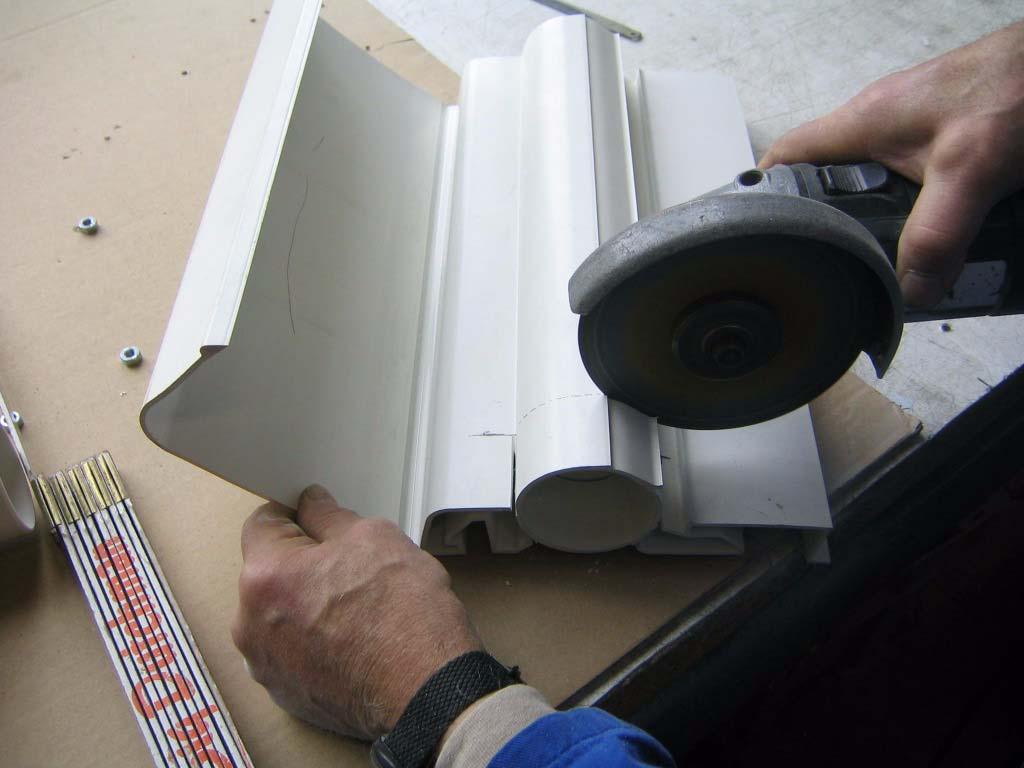
26 Page 23 Assembly Rainmaker Using an angle grinder or saw cut out the integrated piping.

27 Assembly Rainmaker Page 24


28 Page 25 Assembly Rainmaker Cut out the corners by hand so that you do not cut into the Top-profile.


29 Assembly Rainmaker Page 26 Cut out deflector.

30 Page 27 Assembly Rainmaker Done! Please fill the gaps on the Top-profile with silicone.

31 Assembly Rainmaker Page Installing the cooling pads & retainers Let the pad retainers snap into the guide rail. After that snap the deflector into the pad retainers. A= Top-profile B= Position pad retainers always between two pads. Note: For center feed systems For center feed, place a Pad Retainer at each side of the T-piece. Pos. Code No. Description 1a Retainer PVC for Pad 150/6"
32 Page 29 Assembly Rainmaker Pos. Code No. Description 1b Retainer PVC for Pad 100/6" 2 Pad
33 Assembly Rainmaker Page Installing the end panels A= Holes are for 2m high pads. Pos. Code No. Description End panel, right, top End panel, right, bottom End panel, left, top End panel, left, bottom Washer 6,4 SST Hexagon head screw M 6x 12 SST DIN Hexagon nut M 6 SST DIN Hexagon wood screw 6x 40 DIN 571-A2 SST
34 Page 31 Assembly Rainmaker 1. Assemble the left hand bottom with the left hand top by loosely attaching the hexagon head screws M6x12 with the M6 nuts through the holes provided. Repeat for right hand. Note: The existing holes are for the 2m pads (6.56ft). If other pad heights are used, move the upper end panel down until the correct position is found. Then make marks on the upper end panel to drill the new 6mm holes.
35 Assembly Rainmaker Page Suggestion for mounting of pump substructure, if Rainmaker system cannot be mounted near ground (optional) Pos. Description 1 Hexagon Bolt 2 Nut 3 Washer 4 Threaded rod 5 Bracket for driptrough 6 Angle bracket 7 Baseplate 1. Screw the angle brackets (6) onto the 2 brackets for the driptrough (5).
36 Page 33 Assembly Rainmaker 2. Mount the threaded rod (4) into the angle brackets (6) as shown above. 3. Cut the baseplate (7) so it has the right size (note distance of the brackets for the reservoir). 4. Drill 4 holes into the baseplate for the pump, to be able to mount the threaded rods. 5. Install the baseplate for the pump. 6. Choose the desired height for the baseplate. NOTE: The pump has to be mounted below the water level Installation of pump connection Center feed (position may not necessarily be exaclty center. Note position of the T-connection) 1. Position the bulkhead fitting (14) a little bit off to the T-piece. See drawing on following page. 2. Cut a hole with 45mm (1.77in) in diameter at the bottom of the driptrough to install the bulkhead fitting. End feed 1. Position the bulkhead fitting on the opposite end of the water supply. The bulkhead fitting can be mounted below (center) the driptrough or can be placed into the end panel. If the bulkhead fitting is fitted into the end panel, please drill the hole as low as possible. 2. Cut a 45mm (1.77in) hole (center) for the fitting. 3. Install the bulkhead fitting and make sure that the gaskets are placed correctly. 4. Mount the water supply (plumbing) as shown Mounting the drain off (driptrough) 1. Drainage (16 / 17): The drain off should be positioned at the opposite end of the float valve. 2. Cut a 40mm (1.6in) hole centerly into the driptrough for the drain off (16 / 17). 3. Install the drain off for the driptrough as shown in the drawing below (16 / 17).
37 Assembly Rainmaker Page Installing the plumbing (center feed) Important: Top view: The pump (2) has to be installed at a distance of approximately 50 cm from the pads (1). The tubes have to be cut accordingly! Protection against splash water: the pump has to be covered with suitable materials. (Attention: do not wrap the pump completely.) A= Water supply B= Important: For center feed systems => Pre-cutout section in the Top-profile for the T-piece. See chapter 2.8.1
38 Page 35 Assembly Rainmaker Pos. Code No. Description Ball valve 63mm PVC NP Coupler for Top-profile PVC Rainmaker Sleeve 63mmx2" Pipe 63mmx3,00 PVC 5a Centrifugal pump # upto 12m padlength CE- IP55/conn. 50 5b Centrifugal pump # upto 30m padlength CE- IP55/conn Float Valve Elbow 63-90deg PVC NP T-piece 63x50Ax63 PVC Ball valve 50mm PVC NP16 10 Screw socket inside 50mm / outside 2inch (60mm) Pipe 50x2,50 PVC Elbow 50-90deg PVC NP Table duct 1 3/4"m x 40/50 PVC Top-profile 100/150x3000 PVC Table duct 1 1/4"m x 32 PVC with clamping nut Cap 1 1/4" PVC T-piece for Top-profile PVC Socket 50mm PVC NP Reducing bush 50od x 20id PVC Hose nozzle 22x20 PVC Hose band clip 3/4" Hose high pressure 3/4" Reducing socket 63 x 50 PVC
39 Assembly Rainmaker Page Installing the plumbing with supply unit (center feed) Important: Top view: The pump (2) has to be installed at a distance of approximately 50 cm from the pads (1). The tubes have to be cut accordingly! Protection against splash water: the pump has to be covered with suitable materials. (Attention: do not wrap the pump completely.) Pos. Code No. Description Ball valve 63mm PVC NP Coupler for Top-profile PVC Rainmaker Sleeve 63mmx2" Pipe 63mmx3,00 PVC 5a Centrifugal pump # upto 12m padlength CE-IP55/ conn. 50 5b Centrifugal pump # upto 30m padlength CE-IP55/ conn Float Valve Elbow 63-90deg PVC NP T-piece 63x50Ax63 PVC Ball valve 50mm PVC NP16 10 Screw socket inside 50mm / outside 2inch (60mm) Pipe 50x2,50 PVC Elbow 50-90deg PVC NP Table duct 1 3/4"m x 40/50 PVC Top-profile 100/150x3000 PVC Table duct 1 1/4"m x 32 PVC with clamping nut Cap 1 1/4" PVC T-piece for Top-profile PVC Socket 50mm PVC NP Reducing bush 50od x 20id PVC Hose nozzle 22x20 PVC Hose band clip 3/4" Hose high pressure 3/4" Supply unit RM 500mm PVC Hose nozzle orange 3/4"fm cpl w/swivel nut and gasket Elbow 63-45deg PVC NP16
40 Page 37 Assembly Rainmaker Pos. Code No. Description 27 Lid for supply unit Reducing socket 63 x 50 PVC A= Water supply B= Important: For center feed systems => Pre-cutout section in the Top-profile for the T-piece. See chapter After the assembly the supply unit is closed with the corresponding lid.
41 Assembly Rainmaker Page Installing the plumbing (end feed) A= Fresh water supply B= Important: For the end feed installation. Install the float valve (6) at the opposite end of the water pump. Pos. Code No. Description Ball valve 63mm PVC NP Coupler for Top-profile PVC Rainmaker
42 Page 39 Assembly Rainmaker Pos. Code No. Description Sleeve 63mmx2" Pipe 63mmx3,00 PVC 5a Centrifugal pump # upto 12m padlength CE- IP55/conn Float Valve Elbow 63-90deg PVC NP T-piece 63x50Ax63 PVC Ball valve 50mm PVC NP16 10 Screw socket inside 50mm / outside 2inch (60mm) Pipe 50x2,50 PVC Elbow 50-90deg PVC NP Table duct 1 3/4"m x 40/50 PVC Top-profile 100/150x3000 PVC Table duct 1 1/4"m x 32 PVC with clamping nut Cap 1 1/4" PVC Socket 50mm PVC NP Ball valve 63mm PVC NP Reducing bush 50od x 20id PVC Hose nozzle 22x20 PVC Hose band clip 3/4" Hose high pressure 3/4" Reducing socket 63 x 50 PVC
43 Assembly Rainmaker Page Installing the plumbing with supply unit (end feed) A= Fresh water supply After the assembly the supply unit is closed with the corresponding lid. Pos. Code No. Description Ball valve 63mm PVC NP Coupler for Top-profile PVC Rainmaker Sleeve 63mmx2"
44 Page 41 Assembly Rainmaker Pos. Code No. Description Pipe 63mmx3,00 PVC 5a Centrifugal pump # upto 12m padlength CE- IP55/conn Float Valve Elbow 63-90deg PVC NP T-piece 63x50Ax63 PVC Ball valve 50mm PVC NP16 10 Screw socket inside 50mm / outside 2inch (60mm) Pipe 50x2,50 PVC Elbow 50-90deg PVC NP Table duct 1 3/4"m x 40/50 PVC Top-profile 100/150x3000 PVC Table duct 1 1/4"m x 32 PVC with clamping nut Cap 1 1/4" PVC Socket 50mm PVC NP Ball valve 63mm PVC NP Reducing bush 50od x 20id PVC Hose nozzle 22x20 PVC Hose band clip 3/4" Hose high pressure 3/4" Supply unit RM 500mm PVC Hose nozzle orange 3/4"fm cpl w/swivel nut and gasket 26 Lid for supply unit Reducing socket 63 x 50 PVC
45 Operation Page 42 3 Operation 3.1 Initial Start-up When the pads are new, their slick surfaces will prevent the fast soaking that will happen with older pads. For this reason, when the pads are used for the first time, it is important to allow the pump to run for one or two days continuously. This will "soak-in" the pads, and allow faster start-up later. These one or two days are called the "breakin" period. At the end of the "break-in" period, inspect pads carefully, any dry streaks will indicate an inconsistent water distribution. If you find these dry streaks, you will need to clean the spray line. To clean the spray line, follow the procedure outlined on the next page Correct water pressure of the system The correct water pressure has been achieved when the water jet sprays approx cm out of the holes (deflector folded up) The water pressure can be adjusted at the ball valve in the supply pipe. 3.2 Normal operation Under normal conditions, the pump should run constantly when air is being drawn through the pads. While the system is in operation you should look for sediments on the pads, which are caused by impurities in the water. If sediments are located increase the bleed off rate.
46 Page 43 Operation 3.3 Extending pad life As you use the Rainmaker, you will notice the need for good preventative maintenance. Algae growth, scale (hard crusty deposits), and dirt accumulation are typical problems associated with poor maintenance. Maintaining the Rainmaker is very simple. It takes a small amount of time and effort. If you follow the guidelines below, your pads will last much longer, and be much more effective. 3.4 Algae treatment If algae develops on pipes, it may be necessary to add a water treatment compound to control algae growth. Consult your local agricultural distributor for a recommended water treatment chemical. 3.5 Limit on-off cycling Many users have initially seen greater cooling effects from evaporative cooling systems when they run the system on a ten minute timer. Although this cooling may have a great short term effect, the pad life is greatly shortened. For this reason, you must choose for yourself which is more important. When the system is started and stopped every ten minutes, the pads are wetted and dried out six times per hour (Up to 144 times per day!). Each time the pads dry, the minerals in the water remain on the pad, and limit the cooling effectiveness. 3.6 Why drain (bleed-off) water from the system Water always contains dissolved minerals. When the pad-cooling system is operating, the water evaporates and the mineral content in the recirculated water increases. To accommodate the water loss fresh water is automatically introduced into the system by the float valve. To prevent too high of a mineral content and sediments on the pads you have to drain some of the recirculating water. The constant water drainage is called bleed off. The amount of water being drained depends on the amount of evaporated water and the mineral content of the water. As rule of thumb you can say that 10% of the water flow at good to moderate water quality. If the water has a very high mineral content the bleed off rate should be the same as the evaporation rate.
47 Operation Page Water distribution Maintaining even water distribution to the pads is the most important way of extending pad life. If an area of a pad does not receive enough water, it will clog or soften. If at any time you see dry spots or streaks, investigate to see why. Most problems associated with water distribution may be fixed with a good cleaning of the spray line. Follow procedures outlined below for cleaning the Rainmaker System. For best results clean the system on a regular basis. 3.8 Cleaning your Rainmaker System 1. Shut off pump and clean strainer. 2. If possible, turn off fans. (If this is not possible, run fans at minimum levels). 3. Gently hose off pads. Clean algae from pads and pipes. 4. Flush reservoir. 5. Flush spray line: (A) Open ball valve at end of spray line (when end feed is used) or open both ball valves (when center feed is used). (B) Turn on pump. (C) Clean for several minutes. 6. Using a long stick clean the spray line with a brush or attach the brush to a rope and pull it through the spray line. Brush off the dirt on the spray line. 7. After flushing spray line: Turn off pump. Close Ball Valve at the end of spray line. 8. Refill reservoir to full level. 9. Resume normal operation. 3.9 Winterize your Rainmaker 1. Turn off pump. 2. Remove strainer cover. In very cold regions remove the pump completely. 3. Remove the drain off cap from the screen basket (pump). 4. Empty out the reservoir.
4-1 1 / 2 " Tees / 2 " hole saw w/ 1/4" drill bit / 2 " Male slip plugs
 Section 1: Parts List 1-50 Flex PVC pipe 2-1 1 / 2 " Ball Valves 4-1/2" 90 degree elbows 4 - Lengths of 1/2" PVC 4 - Jet bodies 4 - Jet nozzles 4 - Female slip/female slip unions 2 - Female slip/fpt union
Hydrotherapy Jets (Remote Water Quality System)
") Page 1 of 6 Parts List (_) - 50 Roll of Flex PVC pipe 1-3/4 HP Circulating Centrifugal Pump 1 25 Roll of Flex PVC pipe 4-1 1 / 2 " Tees 2-1 1 / 2 " Ball Valves 2 - Female slip couplers 4-1/2" 90 degree
Page 1 of 6 Parts List (_) - 50 Roll of Flex PVC pipe 1-3/4 HP Circulating Centrifugal Pump 1 25 Roll of Flex PVC pipe 4-1 1 / 2 " Tees 2-1 1 / 2 " Ball Valves 2 - Female slip couplers 4-1/2" 90 degree
PolyMax H2-24 Dutch Bucket System
 11234 PolyMax H2-24 Dutch Bucket System *Actual system may differ. PolyMax Dutch Buckets Versatile PolyMax Dutch Buckets are ideal for both small- and large-scale hydroponic growing. 2017 FarmTek All Rights
PolyMax H1-10 Dutch Bucket System
 112529 PolyMax H1-10 Dutch Bucket System *Actual system may differ. PolyMax Dutch Buckets Versatile PolyMax Dutch Buckets are ideal for both small- and large-scale hydroponic growing. STK# DIMENSIONS 112529
Clean Water Made Easy. CWS Time Clock Softener Installation & Start Up Guide. Questions?
 Clean Water Made Easy www.cleanwaterstore.com CWS Time Clock Softener Installation & Start Up Guide Thank you for purchasing a Clean Water System! With proper installation and a little routine maintenance
OVE ORDERING INFORMATION NOTES T01-A INSTALLATION INSTRUCTIONS ELONGATED TWO-PIECE TOILET K-17737T/K-17737T-S
 OVE INSTALLATION INSTRUCTIONS ELONGATED TWO-PIECE TOILET K-17737T/K-17737T-S Please read these instructions carefully to familiarize yourself with the required tools, materials, and installation sequences.
HydroCycle Vertical Aeroponic Systems
 HydroCycle Vertical Aeroponic Systems 2018 Growers Supply All Rights Reserved. Reproduction is prohibited without permission. *Actual system may differ from system shown. 113593 8' Vertical System (44
REVE ORDERING INFORMATION NOTES T01-A INSTALLATION INSTRUCTIONS 现代型分体座便器 CONTEMPORARY TWO-PIECE TOILET K-17178T-S/K-17178T-SP
 REVE INSTALLATION INSTRUCTIONS 现代型分体座便器 CONTEMPORARY TWO-PIECE TOILET K-17178T-S/K-17178T-SP Please read these instructions carefully to familiarize yourself with the required tools, materials, and installation
INSTALLATION AND OPERATION. -, 3. -is INSTRUCTIONS FOR COOLAIR S EVAP-PAD COOLING SYSTEM. Coo/ah AMERICAN COOLAIR CORPORATION
 I -, 3. -is INSTALLATION AND OPERATION INSTRUCTIONS FOR COOLAIR S EVAP-PAD COOLING SYSTEM e Coo/ah AMERICAN COOLAIR CORPORATION TABLE OF CONTENTS PAGE I. CONCEPT OF EVAPORATIVE COOLING....2 II. RECOMMENDEDTOOLS......3
Remote Water Quality System Standard Equipment (supplied by EPI) Remote Water Quality System Optional Equipment (supplied by EPI)
 Remote Water Quality System Optional Equipment (supplied by EPI)") Page 1 of 11 Parts List Remote Water Quality System Standard Equipment (supplied by EPI) 20sq ft Skimmer-Filter Remote Water Quality Plumbing Kit Heater-Controller Keypad Control 220V 3/4HP Circulation
Page 1 of 11 Parts List Remote Water Quality System Standard Equipment (supplied by EPI) 20sq ft Skimmer-Filter Remote Water Quality Plumbing Kit Heater-Controller Keypad Control 220V 3/4HP Circulation
Portable Evaporative Cooling System
 Portable Evaporative Cooling System User s Manual Manufactured by HH Technologies, Inc. 1733 County Road 68 Bremen, Alabama 35033 256-287-7000 Part No 4801-5035 Rev 03-2017 User s Manual PolarCool Table
Owner s Manual. Keep with machine for reference PKC24 INSTALLATION & OPERATION REV Perlick Corporation 8300 W Good Hope Rd Milwaukee, WI 53223
 Owner s Manual Keep with machine for reference PKC24 INSTALLATION & OPERATION REV.11.09 Perlick Corporation 8300 W Good Hope Rd Milwaukee, WI 53223 800-558- 5592 FAX 414-353- 7069 perlick.com TABLE OF
VM99 TANK REPLACEMENT PARTS 1. COVER BOLT BOLT (4 REQ'D FOR 21-34), 1/4"-20 x 1" THERMAL CUT-OUT THERMAL TRIP PLUG
, 1/4-20 x 1 THERMAL CUT-OUT THERMAL TRIP PLUG") VM99 TANK REPLACEMENT PARTS 1. COVER BOLT BOLT (4 REQ'D FOR 21-34), 1/4"-20 x 1" 700300-013 2. THERMAL CUT-OUT 409560-001 THERMAL TRIP PLUG 409210-010 3. HEATER TERMINAL COVER VM99 2-4 HEATER TERMINAL
VM99 TANK REPLACEMENT PARTS 1. COVER BOLT BOLT (4 REQ'D FOR 21-34), 1/4"-20 x 1" 700300-013 2. THERMAL CUT-OUT 409560-001 THERMAL TRIP PLUG 409210-010 3. HEATER TERMINAL COVER VM99 2-4 HEATER TERMINAL
L24TWS. Beverage Tower Kit Components. L24TWD Lynx Beverage Kits Model L24TWS Single Tower and L24TWD Double Tower
 Installation, Care and Use of Your Lynx Beverage Tower Kits MOM FRIENDLY. DAD READY. L24TWS Beverage Tower Kit Components L24TWD Lynx Beverage Kits Model L24TWS Single Tower and L24TWD Double Tower Introduction:
Installation Instructions. For the 18 Built-In Dishwasher and Front Color Panels
 Installation Instructions For the 18 Built-In Dishwasher and Front Color Panels Printed in USA 154232102 Before You Begin DO NOT INSTALL DISHWASHER UNTIL YOU HAVE READ ALL INSTRUCTIONS. FOR YOUR SAFETY,
Installation Instructions for. WaterMaster Series Fountains
 Installation Instructions for WaterMaster Series Fountains Congratulations, you have just purchased the finest watering fountain on the market. This unit is built to give you excellent service when properly
CBT LW MAINTENANCE GUIDE
 CBT LW MAINTENANCE GUIDE PICTOGRAMS Each Signifier displayed here is specific to this User Manual. Menu Previous Advance Note Tip Example Powder Feeder Mixing Bowl Weigh Scale CBP Tanks Control Panel PSD
PIPE DREAMS 96. Aeroponic Garden IMPORTANT:
 1 WARNING: BEFORE PUTTING WATER PUMP INTO OPERATION FILL UP NUTRIENT TANK TO TOP OF PUMP. THE PUMP MUST NEVER RUN DRY OTHERWISE, WARRANTY WILL BE DECLINED. READ FILLING INSTRUCTIONS BEFORE USE. Welcome
METIS. Installation instructions. Riser rail kit INSTALLERS PLEASE NOTE THESE INSTRUCTIONS ARE TO BE LEFT WITH THE USER.
 METIS Riser rail kit Installation instructions INSTALLERS PLEASE NOTE THESE INSTRUCTIONS ARE TO BE LEFT WITH THE USER 2180531A September 2006 CONTENTS Page General installation notes 1 Main components
Safety. Rinse Kit for Multi-Pro 1200 and 1250 Turf Sprayers Model No Safety and Instructional Decals. Installation Instructions
 Rinse Kit for Multi-Pro 1200 and 1250 Turf Sprayers Model No. 106-4842 Form No. 3353-529 Rev B Installation Instructions Note: Determine the left and right sides of the machine from the normal operating
Heat Exchanger Block Replacement Instructions
 Series 1-4 Gas-fired water boiler Heat Exchanger Block Replacement Instructions Ultra-80 S1-4 Heat Exchanger Block Replacement Kit, Part No. 383-500-773 Ultra-105 S1-4 Heat Exchanger Block Replacement
Installation Instructions for. WaterMaster Series Fountains
 Installation Instructions for WaterMaster Series Fountains Congratulations, you have just purchased the finest watering fountain on the market. This unit is built to give you excellent service when properly
Electrical cable Water supply tube Fittings for tube Coupler Teflon tape. Hole saw min. 2½" bit
 Installation Parts and Tools Parts not Provided Electrical cable Water supply tube Fittings for tube Coupler Teflon tape Air gap Wire nuts for 6-gauge wiring Hose clamp ⅞" UL approved strain relief Electrical
REVE ORDERING INFORMATION NOTES T01-E INSTALLATION INSTRUCTIONS ELONGATED TWO-PIECE TOILET K-17178T-S2/K-17178T-SBG2/K-17178T-SP2
 REVE INSTALLATION INSTRUCTIONS ELONGATED TWO-PIECE TOILET K-17178T-S2/K-17178T-SBG2/K-17178T-SP2 Please read these instructions carefully to familiarize yourself with the required tools, materials, and
ICE MAKER Use & Care Guide. Table of Contents... 2
 ICE MAKER Use & Care Guide Table of Contents... 2 2217247 ICE MAKER SAFETY...2 ICE MAKER INSTALLATION...3 Unpacking...3 Location Requirements...3 Electrical Requirements...3 Leveling...4 Water Supply Connection...4
INSTALLATION INSTRUCTIONS UNDERCOUNTER DISHWASHERS
 INSTALLATION INSTRUCTIONS UNDERCOUNTER DISHWASHERS VIKING 111 Front Street Greenwood, Mississippi 38930 USA (662) 455-1200 IMPORTANT - PLEASE READ AND FOLLOW Before beginning - please read these instructions
GLC/GW-100 MANUAL INSTALLATION SERVICE PARTS REV.1.01
 Owner s Manual Keep with machine for reference GLC/GW-100 MANUAL INSTALLATION SERVICE PARTS REV.1.01 CMA DISHMACHINES 12700 KNOTT STREET GARDEN GROVE, CALIFORNIA 92841 800-854- 6417 FAX 714-895- 2141 www.cmadishmachines.com
NEPTUNE Steam Room Installation Instructions
 NEPTUNE Steam Room Installation Instructions IMPORTANT Please read carefully the following instructions before installing your shower cabin. If you have any questions on this shower cabin installation
HydroCycle Vertical Aeroponic Systems
 HydroCycle Vertical Aeroponic Systems 2018 Growers Supply All Rights Reserved. Reproduction is prohibited without permission. 113700 4' Vertical System (24 Grow Sites) Revision date: 01.10.18 1 Important
MODEL CMA-180UC PARTS MANUAL Rev 1.16
 MODEL CMA-180UC PARTS MANUAL Rev 1.16 CMA DISHMACHINES 12700 KNOTT STREET GARDEN GROVE, CALIFORNIA 92841 800-854-6417 FAX 714-895-2141 wwwcmadishmachines.com TABLE OF CONTENTS MODEL CMA-180UC 1. PARTS
Installation Instructions for. OmniFount
 Installation Instructions for OmniFount Congratulations, you have just purchased the finest watering fountain on the market. This unit is built to give you excellent service when properly installed and
Acrylic Claw Foot Tub
 Acrylic Claw Foot Tub Wrench or socket Drill & Bits Parts Recommended 2-2 x12 boards 4 Lag Bolts 4 Flat Washers Be sure to re-inforce the floor before securing tub. We recommend 2-2 x12 s securely fastened
Owner's Manual. WS Series. Water Softener
 Owner's Manual WS-165-150 Series Water Softener Table of Contents WHAT'S INCLUDED 3 OPERATING CONDITIONS 4 ASSEMBLY INSTRUCTIONS 6 FLUSHING THE WATER LINES 13 MASTERPROGRAMMING 14 PROGRAMMING KEYAND GENERAL
Installation and Care Instructions
 Installation and Care Instructions 2" Horizontal Aluminum Blinds MagnaView Tilt Feature CONTENTS Getting Started................................................ 1 Mount the Installation s....................................
Installation Instructions
 Installation Instructions KFN 9855 ide en - CA Installation, repair and maintenance work should be performed by a Miele authorized service technician in accordance with national and local safety regulations
INSTALLATION INSTRUCTIONS
 INSTALLATION INSTRUCTIONS 3580079 3580006 MODEL: LUGARNO 3580006 (RH-5900) 3580079 (RH-5900L) REV C Restoration Hardware Faucet Product Size Specification Diagram Recommended Deck Hole Size -3/8 Diameter
Installation Instructions
 Installation Instructions For Fully Integrated NoFrost Combined Refrigerator-Freezers HC 2062 HCB 2062 HC/HCB 20 7082 373-00 Important PLEASE READ AND FOLLOW THESE INSTRUCTIONS These instructions contain
Portable Evaporative Cooling System
 Portable Evaporative Cooling System User s Manual Manufactured by HH Technologies, Inc. 1733 County Road 68 Bremen, Alabama 35033 256-287-7000 Part No 4801-5035 Rev 03-2017 User s Manual PolarCool Table
Fleck 2510 SXT Catalox Installation & Start Up Guide
 Fleck 2510 SXT Catalox Installation & Start Up Guide For Catalox Filters with PotPerm Bleach Solution Tank Thank you for purchasing a Clean Water System! With proper installation and a little routine maintenance
SAN RAPHAEL GRANDE ORDERING INFORMATION NOTES T01-B INSTALLATION INSTRUCTIOINS 4.8L SKIRTED CLASS FIVE ONE-PIECE TOILET 4.
 SAN RAPHAEL GRANDE INSTALLATION INSTRUCTIOINS 4.8L SKIRTED CLASS FIVE ONE-PIECE TOILET 4.8 S-TRAP 305mm K-8688T-S S-TRAP 400mm K-18728T-S Please read these instructions carefully to familiarize yourself
- 1 - Updated on 18 March, 2010
 - 1 - Updated on 18 March, 2010 TABLE OF CONTENTS 1. SPECIFICATION & PARTS IDENTIFICATION...3 2. OPERATION & FUNCTION OF PARTS...4, 5 A. Cooling Operation B. Heating Operation C. Function of Parts 3. LOCATION
Installation Instructions
 Installation Instructions For Fully Integrated NoFrost Combined Refrigerator-Freezers HC 2060/2061 7082 485-00 Important PLEASE READ AND FOLLOW THESE INSTRUCTIONS These instructions contain Warning and
Clean Water Made Easy
 Clean Water Made Easy http://www.cleanwaterstore.com Pro-OX 1650 Iron Filter Installation & Start-Up Guide Thank you for purchasing a Clean Water System! With proper installation and a little routine maintenance
FILTRATION SYSTEM MODEL: FILTER - 5 MULTI-SHIFTER, INC. P.O. BOX CHARLOTTE, N.C TEL#: FAX#:
 FILTRATION SYSTEM MODEL: FILTER - 5 MULTI-SHIFTER, INC. P.O. BOX 411047 CHARLOTTE, N.C. 28241-1047 TEL#: 1-704-588-9611 FAX#: 1-704-588-4730 CONTENTS 1. System Overview 2. Air and Electrical Requirements
Curb Inlet Filter INSTALLATION MANUAL. Bio Clean Environmental Services, Inc. 398 Via El Centro Oceanside, CA 92058
 Curb Inlet Filter INSTALLATION MANUAL Bio Clean Environmental Services, Inc. 398 Via El Centro Oceanside, CA 92058 www.biocleanenvironmental.com p: 760.433.7640 f: 760.433.3176 INSTALLATION PROCEDURES
ONE PIECE TOILET LT3. Model: MPN: B0940 INSTALLATION INSTRUCTIONS. Version: 1.0
 Model: MPN: B0940 INSTALLATION INSTRUCTIONS Version: 1.0 READ ALL INSTRUCTIONS BEFORE UNPACKING THE PRODUCT INSTRUCTIONS THAT, IF IGNORED COULD RESULT IN DEATH OR SERIOUS INJURY CAUSED BY INCORRECT HANDLING
TABLE OF CONTENTS FOR YOUR SAFETY
 TABLE OF CONTENTS 1. SPECIFICATION & PARTS IDENTIFICATION...2 2. OPERATION & FUNCTION OF PARTS...2, 3 A. Cooling Operation B. Heating Operation C. Function of Parts 3. LOCATION REQUIREMENTS...3, 4 4. INSTALLATION
How to Build A State-of-the-Art, High Yielding Aeroponic Growing System
 How to Build A State-of-the-Art, High Yielding Aeroponic Growing System Table Of Contents: Page I. Introduction 3 a. What is Aeroponics? 3 b. Why is aeroponics used? 3 II. What You Will Need and Where
SAVE THESE INSTRUCTIONS
 Built-In Dishwasher Dishwashers Write the model and serial numbers here: Model # Serial # You can find them on the tub wall just inside the door or. the lower part of back. Installation Instructions DDW1802W
INSTRUCTIONS FOR USE PORTABLE VACUUM SYSTEM LEI Part # s / , , , IMPORTANT INFORMATION
 INSTRUCTIONS FOR USE PORTABLE VACUUM SYSTEM LEI Part # s / 27-009, 27-010, 27-015, 27-020 IMPORTANT INFORMATION UNATHORIZED CHANGES OR ALTERATIONS TO ANY LINCOLN PORTABLE VACUUM SYSTEM WILL AUTOMATICALLY
Installation and Care Instructions
 Installation and Care Instructions 2" Horizontal Aluminum Blinds MagnaView Tilt Feature Thank you for your purchase. Your new blinds have been custom built for you from the highest quality materials. Properly
INSTALLATION INSTRUCTIONS
 INSTALLATION INSTRUCTIONS 67000 6700 MODEL: SPRITZ 67000 (RH-600) 6700 (RH-600X) REV.C Restoration Hardware Faucet Product Size Specification Diagram Recommended Deck Hole Size -/8 Diameter Dimensions
Fleck 2510 Softener Installation & Start Up Guide
 Clean Water Made Easy www.cleanwaterstore.com Fleck 2510 Softener Installation & Start Up Guide Thank you for purchasing a Clean Water System! With proper installation and a little routine maintenance
Scale Stopper Plus Installation & Start-Up Guide
 Clean Water Made Easy www.cleanwaterstore.com Scale Stopper Plus Installation & Start-Up Guide Thank you for purchasing a Clean Water System! With proper installation and a little routine maintenance your
MODEL CMA-180UC PARTS MANUAL Rev 1.18
 MODEL CMA-180UC PARTS MANUAL Rev 1.18 CMA DISHMACHINES 12700 KNOTT AVENUE GARDEN GROVE, CALIFORNIA 92841 800-854-6417 FAX 714-895-2141 wwwcmadishmachines.com TABLE OF CONTENTS MODEL CMA-180UC 1. PARTS
Fleck 5600 Carbon Filter Installation & Start Up Guide
 Clean Water Made Easy www.cleanwaterstore.com Fleck 5600 Carbon Filter Installation & Start Up Guide Thank you for purchasing a Clean Water System! With proper installation and a little routine maintenance
COBRA -H EXTRACTOR 120V
 COBRA -H EXTRACTOR 120V INFORMATION & OPERATING INSTRUCTIONS CAUTION: DO NOT OPERATE MACHINE UNTIL YOU HAVE READ ALL SECTIONS OF THIS INSTRUCTION MANUAL IMPROPER USE OF THE MACHINE WILL VOID THE WARRANTY
WELLWORTH WATERGUARD VITREOUS CHINA SIPHON JET TOILET
 WELLWORTH WATERGUARD VITREOUS CHINA SIPHON JET TOILET 1. BEFORE YOU BEGIN HOW TO USE THESE INSTRUCTIONS Please read these instructions carefully to familiarize yourself with the required tools, materials,
Handshower, Hose & Handshower Accessories
 P24443, P24445, P24446, P24452, P24453, P24456 1 of 6 INSTALLATION INSTRUCTIONS Thank You For Choosing KALLISTA We appreciate your commitment to KALLISTA quality products. Please take a moment to review
SAN JUAN FRESH WATER COOLING SYSTEMS
 SAN JUAN FRESH WATER COOLING SYSTEMS 4.3-5.7 GI VOLVO Block Only Cooling, Mounted Off Engine Kit #V-111 Installation Instructions San Juan Engineering Heat Exchangers provide thermostatically controlled
Acrylic Claw Foot Tub
 Acrylic Claw Foot Tub Wrench or socket Drill & Bits Parts Recommended 2-2 x12 boards 4 Lag Bolts 4 Flat Washers Be sure to re-inforce the floor before securing tub. We recommend 2-2 x12 s securely fastened
541D19 SERIES. Technical Manual. A Division of Aquion Partners L.P.
 541D19 SERIES Technical Manual A Division of Aquion Partners L.P. Table of Contents Introduction... Page 1 Technical Specifications... Page 2 Flow Diagrams... Page 3 Injector & Flow Control Selection Injector...
Instructions Apply For Model PHTT-6P-KFC. Panel Shelf Is Removed to install warming drawers
 Installation Tips and Procedure For OTR-KFC Table Assembly And Auto-Fill Connection Instructions Apply For Model PHTT-6P-KFC TO DETERMINE TABLE PLACEMENT: Faces Front: Control Side of the units. APPROVED
Kinetico 2060f OD Sulfur Guard Installation Instructions
 SAFETY GUIDELINES Read all steps, guides, and rules carefully before installing and using the Kinetico 2060f OD Sulfur Guard. Check your local building and sanitation codes for installation compliance.
SAN RAPHAEL PRESSURE LITE VITREOUS CHINA SIPHON JET TOILET
 SAN RAPHAEL PRESSURE LITE VITREOUS CHINA SIPHON JET TOILET BEFORE YOU BEGIN HOW TO USE THESE INSTRUCTIONS Please read these instructions carefully to familiarize yourself with the required tools, materials,
Installation Instructions
 Installation Instructions For the 18" Built-In Dishwasher Sears, Roebuck and Co. Sears Canada, Inc. Hoffman Estates, IL 60179 U.S.A. Toronto, Ontario, Canada M5B 2B8 154435201 Before You Begin DO NOT INSTALL
Flush Jet Technology. Technical Specifications and Installers Manual
 Flush Jet Technology Technical Specifications and Installers Manual INDEX TECHNICAL DATA SHEETS Page3 PRODUCT TECHNICAL DATA SHEET IDENTIFICATION: PART NUMBER PRODUCT NAME JAI6SPL1-XX Body Impressions
Ariel PlAtinum AnnA tb222m installation guide
 Ariel Platinum ANNA TB222M installation guide ARIEL PLATINUM TOILET MANUAL INVISIBLE L-MOUNT BRACKETS TABLE OF CONTENTS 1. Sizing and Details 2. Necessary Tools and Materials 3. Precautions Before Installation
Graber Lake Forest Faux Wood and Premium Faux Wood Blind
 2 3 5 6 8 7 1 2" (5.1cm) Blind shown 1. Blind (cord tilt shown) 2. Mounting Brackets 3. Center support bracket (if required). Mounting screws (2 per bracket) 5. Projection brackets (optional, one per mounting
CU1526, CU2026, CU3030 Service Parts
 This is the illustrated list of service parts for all models of the CU, CU0 and CU00 self contained ice machines. These machines were manufactured in several voltages, which is designated by a numeric
Maintenance 5-1. Good maintenance is essential for cleaning results, and long economical life of the washer.
 Maintenance 5-1 5 Maintenance Purpose This chapter discusses the maintenance of your StingRay Parts Washer. In general, the washer is not maintenance-intensive. A few key items, however, need regular,
INSTALLATION INSTRUCTIONS. WOOD BLINDS 1-3/8, 2 and 2-3/8 SLAT SIZES. COMPOSITE FAUX WOOD BLINDS 2 and 2-1/2 SLAT SIZES
 INSTALLATION INSTRUCTIONS WOOD BLINDS 1-3/8, 2 and 2-3/8 SLAT SIZES COMPOSITE FAUX WOOD BLINDS 2 and 2-1/2 SLAT SIZES POLYMER FAUX WOOD BLINDS 2 and 2-1/2 SLAT SIZES STANDARD CORDLESS LIFT Thank you for
Operation and Maintenance Manual 120V/60HZ
 Operation and Maintenance Manual 120V/60HZ GLACIER CS5-16-VD CS5-16-VD-TB CS5-18-VD CS5-18-VD-TB AVALANCHE CS6-36-1D CS6-36-VD BLIZZARD CS6-50-VD Operation & Maintenance Manual 60HZ Models Table of Contents:
Installation Guide. Pedicure Spa D K-163, K-1006, K-1011, K-1012
 Installation Guide Pedicure Spa K-163, K-1006, K-1011, K-1012 1063564-2-D Important Information WARNING: When using electrical products, basic precautions should always be followed, including the following:
Installation Manual PS-200 & PS-201
 Installation Manual PS-200 & PS-201 Table of Contents Pre-Uncrating Checklist... 1 Verifying System Requirements... 2 Verifying System Direction... 2 Verifying the Electrical Requirements... 2 Removal
RiteTemp. Evaporative Cooler. Information Brochure (internal) RiteTemp. RiteTemp. Date: 03/30/05. Cool-Air 5051
 RiteTemp. RiteTemp. Date: 03/30/05. Cool-Air 5051") Evaporative Cooler Information Brochure (internal) Cool-Air 5051 Introduction to use of Evaporative Cooler Benefits of Unit Basic Operation and Maintenance Frequently Asked Questions Atlanta, Ga Phone:
Evaporative Cooler Information Brochure (internal) Cool-Air 5051 Introduction to use of Evaporative Cooler Benefits of Unit Basic Operation and Maintenance Frequently Asked Questions Atlanta, Ga Phone:
Rycroft Supapac Plate Heat Exchangers
 Rycroft Supapac Plate Heat Exchangers Installation Operation & Maintenance Manual Ormandy Rycroft Duncombe Road Bradford BD8 9TB England TEL +44 (0)1274 490911 FAX +44 (0)1274 498580 www.rycroft.com 1.
IMPORTANT SAFETY INSTRUCTIONS WARNING: When using electric appliances, basic
 INSTRUCTIONS PERTAINING TO; RISK OF FIRE, ELECTRIC SHOCK OR HARM TO PERSONS IMPORTANT SAFETY INSTRUCTIONS WARNING: When using electric appliances, basic precautions should always be followed, including
Page 1 of 18. Part# /5/2013
 Part# 1002655-06 8/5/2013 This manual contains important information concerning the installation and operation of the gun washers listed above. Read manual thoroughly and keep for future reference INSTRUCTIONS
5900S Softener Installation & Start-Up Guide
 Clean Water Made Easy www.cleanwaterstore.com 5900S Softener Installation & Start-Up Guide Thank you for purchasing a Clean Water System! With proper installation and a little routine maintenance your
Karess ORDERING INFORMATION NOTES T01-A INSTALLATION INSTRUCTIONS
 Karess INSTALLATION INSTRUCTIONS VITREOUS CHINA TWO-PIECE TOILET S-TRAP 305mm K-5331T-S S-TRAP 400mm K-5471T-S Please read these instructions carefully to familiarize yourself with the required tools,
Zip Econoboil. On wall boiling water. Installation instructions & user manual. Model number: ,
 Zip Econoboil On wall boiling water. Model number: 305542, 303542 1 Table of contents Intended Use... 2 Warnings and precautions... 3 Before installation... 5 Technical specification... 6 Installation
Aluminum Horizontal Blinds BOX BRACKET INSTALLATION
 Aluminum Horizontal Blinds BOX BRACKET INSTALLATION MOUNT THE INSTALLATION BRACKETS Mounting Options The installation brackets may be inside mounted, outside mounted or ceiling mounted. In all cases, level
I-VICFLEX.AB4. Victaulic VicFlex Style AB4 Sprinkler Fitting for Hat Furring Channel Ceiling Systems WARNING INSTALLATION INSTRUCTIONS
 INSTALLATION INSTRUCTIONS I-VICFLEX.AB Victaulic VicFlex Style AB Sprinkler Fitting for Hat Furring Channel Ceiling Systems Read and understand all instructions before attempting to install any Victaulic
American Hydro Systems
 Caution: Read all instructions carefully before beginning the installation Siphoning Systems Keep this manual handy for future reference Owner s Manual INSTALLATION OPERATION PARTS LIST DOSAGE Our Siphoning
PALARRE, ROCHELLE WATER-GUARD VITREOUS CHINA SIPHON JET TOILET
 PALARRE, ROCHELLE WATER-GUARD VITREOUS CHINA SIPHON JET TOILET BEFORE YOU BEGIN HOW TO USE THESE INSTRUCTIONS Please read these instructions carefully to familiarize yourself with the required tools, materials,
Installation Manual PS-225 & PS-275
 Installation Manual PS-225 & PS-275 Table of Contents Pre-Uncrating Checklist... 1 Verifying System Requirements... 2 Verifying System Direction... 2 Verifying the Electrical Requirements... 2 Removal
Ebb & Flow System
 113501 Ebb & Flow System Actual system may differ from what is shown. System requires a timer to control the main pump and to set watering cycles. Additional purchase required. 2016 FarmTek All Rights
Clean Water Made Easy
 Clean Water Made Easy http://www.cleanwaterstore.com Pro-OX 5700-E Iron Filter Installation & Start-Up Guide Thank you for purchasing a Clean Water System! With proper installation and a little routine
Operation and Maintenance Manual BLIZZARD50 CS6-50-VD 120V/60HZ
 Operation and Maintenance Manual BLIZZARD50 CS6-50-VD 120V/60HZ CS6-50-VD Operation & Maintenance Manual Table of Contents: 1.0 Introduction 1 2.0 Unpacking your COOL- SPACE 1 3.0 Set-up of COOL-SPACE
Dishwasher Installation Instructions DW 24XT/DW 24XV
 Dishwasher Installation Instructions DW 24XT/DW 24XV Installation Instructions Dishwasher BEFORE YOU BEGIN Read these instructions completely and carefully. IMPORTANT Observe all governing codes and ordinances.
EFFECTIVE: MAY, American Dish Service ADS MODEL: ASQ GLASSWASHER PARTS MANUAL. 900 Blake Street Edwardsville, Kansas (913) /08
 /08") EFFECTIVE: MAY, 2008 American Dish Service ADS MODEL: ASQ GLASSWASHER PARTS MANUAL 900 Blake Street Edwardsville, Kansas 66111 (913)422-3700 05/08 021-0061 Model: ASQ Glasswasher American Dish Service
EFFECTIVE: MAY, 2008 American Dish Service ADS MODEL: ASQ GLASSWASHER PARTS MANUAL 900 Blake Street Edwardsville, Kansas 66111 (913)422-3700 05/08 021-0061 Model: ASQ Glasswasher American Dish Service
Nilfisk Inc Winnetka Avenue North Minneapolis, MN REV.03( ) VF80189
 VF80189") Nilfisk Inc. 9435 Winnetka Avenue North Minneapolis, MN 55445 www.usviper.com REV.03(05-) VF8089 SAFETY PRECAUTIONS This machine is intended for commercial use. It is constructed for use in an indoor
Nilfisk Inc. 9435 Winnetka Avenue North Minneapolis, MN 55445 www.usviper.com REV.03(05-) VF8089 SAFETY PRECAUTIONS This machine is intended for commercial use. It is constructed for use in an indoor
Installation Instructions
 GE Consumer & Industrial Appliances Installation Instructions Junction Box Cover Within this user bag, you will find a junction box cover and a #10 hex head screw used to attach the junction box cover
COMMERCIAL STRENGTH POLYMER MEDIA FILTER OWNERS MANUAL
 COMMERCIAL STRENGTH POLYMER MEDIA FILTER OWNERS MANUAL INTRODUCTION Congratulations on choosing the Poolrite S6000 mk2, S5000 mk2, S8000 mk1 or S9000 mk4 High Rate Media Filter fitted with the exclusive
Installation Instructions
 GE Consumer & Industrial Appliances Installation Instructions Junction Box Cover Within this user bag, you will find a junction box cover and a #10 hex head screw used to attach the junction box cover
Installation, Operation and Maintenance Instructions for ThermaFlex Gasketed Plate Heat Exchangers
 OM010 Installation, Operation and Maintenance Instructions for ThermaFlex Gasketed Plate Heat Exchangers The operating and maintenance instructions contained within this package are for ThermaFlex gasketed
ADAIR ORDERING INFORMATION T01-A
 ADAIR INSTALLATION INSTRUCTIONS 4.0L SKIRTED CLASS FIVE+ 2PC TOILET 4.0 S-TRAP 305mm K-8699T/K-8699T-S S-TRAP 400mm K-8947T/K-8947T-S Please read these instructions carefully to familiarize yourself with
IB 835. Installation Manual. Integrated Bidet Toilet TABLE OF CONTENTS
 IB 835 Installation Manual Integrated Bidet Toilet Cautions before installation Water supply should have a minimum water pressure of 10 psi For smooth drainage, water pressure must stay at its required
ADVANTAGE-100H-SC EXTRACTOR
 ADVANTAGE-100H-SC EXTRACTOR 120V INFORMATION & OPERATING INSTRUCTIONS CAUTION: DO NOT OPERATE MACHINE UNTIL YOU HAVE READ ALL SECTIONS OF THIS INSTRUCTION MANUAL IMPROPER USE OF THE MACHINE WILL VOID THE