INVITATION TO BID FAILURE TO SIGN WILL DISQUALIFY BID Bid No.: #GK-MECH-YARD ADDENDUM NO. 1
|
|
|
- Margery Rice
- 5 years ago
- Views:
Transcription
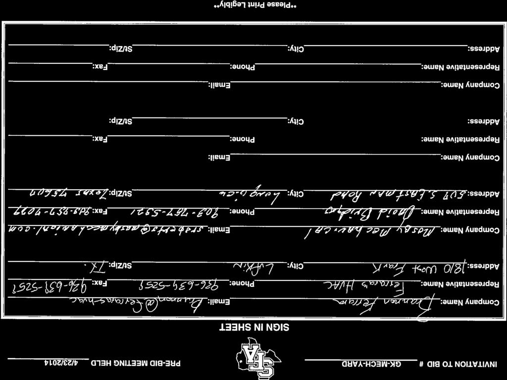
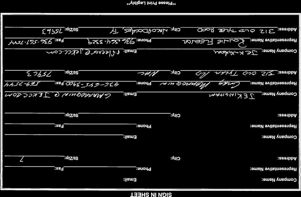
1 INVITATION TO BID FAILURE TO SIGN WILL DISQUALIFY BID Bid No.: #GK-MECH-YARD ADDENDUM NO. Signature City Zip Due Date: May, 04 at 3:00 P.M. Show bid opening and bid invitation number in lower left hand corner of sealed bid envelope and return sealed bids to: Printed Name VENDOR NAME AND ADDRESS Name of Firm PHONE/FAX Phone Stephen F. Austin State University P. O. Box 3030, SFA Station 4 Wilson Drive Mailing Address FAX Nacogdoches, Texas Phone (936) FAX (936) (See.3 reverse side) City State Zip See Instruction.0 on Back for Vendor ID Number Delivery in Days Cash Disc. % Days Is Vendor a State of Texas certified HUB? Yes Check all that apply if Preference Claimed under Rule 34 TAC 0.38 Products of persons with mental or physical disabilities Supplies, materials or equipment: produced in TX/offered by TX bidders* Agricultural products grown in TX Agricultural products offered by TX bidders* Products made of recycled, remanufactured, or environmentally sensitive materials Energy efficient products Rubberized asphalt paving material USA produced supplies, materials or equipment Recycled motor oil and lubricants Products produced at facilities located on formerly Products and services from economically depressed contaminated property or blighted areas *By signing this bid, bidder certifies that if a Texas address is shown as the address of the bidder, bidder qualifies as a Texas resident Bidder as defined in Rule 34 TAC IF QUOTING OTHER THAN THE REFERENCED ITEM(S) BELOW, BROCHURE AND/OR SPECIFICATIONS SHOULD BE ENCLOSED. ALL BIDS WILL BE CONSIDERED F.O.B. DESTINATION UNLESS OTHERWISE NOTED. AWARD NOTICE: Stephen F. Austin State University (SFASU) reserves the right to make an award on the basis of low line item bid, low total of line items, or in any other combination that will serve the best interest of SFASU and to reject any and all bid items in the sole discretion of SFASU. Item No. Description Qty. & Unit Unit Price Extension Quote price on quantity and unit of measure, extend and show total. If error in extension, unit price shall govern. Items for state use are exempt from state sales and federal excise tax. Do not include tax in your bid. ADDENDUM NO. THIS ADDENDUM MUST BE ACKNOWLEDGED IN ORDER FOR THE RESPONSE TO RECEIVE CONSIDERATION. FAILURE TO ACKNOWLEDGE THE ADDENDUM WILL RESULT IN DISQUALIFICATION OF THE RESPONSE. PRE-BID MEETING/SITE VISIT SIGN-IN SHEETS The sign-in sheets from the mandatory pre-bid meeting/site visit held 4/3/4 are attached. CHANGE IN INVITATION TO BID OPENING DATE The Bid Due Date/Time has change to 05/0/04 3:00PM SPECIFICATIONS Completed Date changed to August 5, 04. All factory authorized startup shall be scheduled and completed before completion date.
2 STEPHEN F. AUSTIN STATE UNIVERSITY INVITATION TO BID #GK-MECH-YARD CONTINUED SFA will supply chill water to Hall 5 & 8 from additional source during construction. As new cooling towers startup contractor shall assist with chill and condenser water change over. Contractor laydown and parking areas shall be located around the mechanical building and across the street at concrete surface lot. Contractor shall supply, coordinate factory startup and installation of two new 300 Ton Evapco cooling towers according to data sheets, drawings and specifications. Exception to the vendor plans: Rotate the East tower s discharge nozzle location shown by 90 degrees clockwise. Rotate the West tower s discharge nozzle location shown by 90 degrees counter-clockwise. QUESTIONS Q: Are the vertical turbins coming out? A: Yes, and the sumps will be filled in.
3

4
 570-4700 Fax (97) 570-407 Project: GK Mech Yard Cooling Tower Engineer: Scott and Strong Architects For pricing and information on the cooling tower for")
5 April 5th, 04 To: Interested Bidders 609 W. Campus Circle Dr., Suite #00 Irving, Texas Office (97) Fax (97) Project: GK Mech Yard Cooling Tower Engineer: Scott and Strong Architects For pricing and information on the cooling tower for this project contact Mike Merrill and Bill Blair with Texas AirSystems. Mike Merrill Bill Blair of 4/4/04
6 Cooling Tower Data Sheet SFA Project : SFA Tower 5 and 8 Equipment Reference: Product Type : AT/UT/USS Cooling Tower Bill Blair Selection Criteria Capacity (Tons): Capacity (MBH): 4, Fluid Type: Water Flow (GPM): Entering Fluid Temp ( F): 95.0 Leaving Fluid Temp ( F): 85.0 Wet Bulb ( F): 79.0 Date: /9/03 Page: IBC Design Criteria Seismic Design Force (g) g Velocity Pressure (psf) up to 60 CTI Certified Cooling Tower Qty Model Capacity Percent Capacity (Tons) USS All Weights, Dimensions and Technical Data are Shown per Unit Overall Length: Overall Width: Overall Height: Fans: # Fan HP: 5.00 (460/3/60) # kw: 4.00 Air Flow (CFM) 7,800 Inlet Pressure Drop (psi):.8 Evaporated Water Rate (gpm): 7.0 Options Selected Fan Motor: Inverter Capable, Premium Efficient EVAPAK Fill IBC Compliant up to g 3-Probe Electronic Water Level Control Package El. Heaters (0F / -8C ambient) () 4 kw Contactor w/transformer and Disconnect for Heater Package Vibration Switch 304 Stainless Steel Cold Water Basin 304 Stainless Steel Upper Ladder '.750'' 8' 5.500'' ' 8.750'' Operating Weight (lbs): 9,470 Shipping Weight (lbs): 5,60 Heaviest Section (lbs): 3,960 evapselect Version: March 03
7 SECTION COOLING TOWERS PART - GENERAL. RELATED DOCUMENTS A. Drawings and general provisions of the Contract, including General and Supplementary Conditions and Division 0 Specification Sections, apply to this Section.. SUMMARY A. This Section includes factory assembled and tested, open circuit mechanical induced-draft vertical discharge cooling tower..3 SUBMITTALS A. Product Data: For each type of product indicated. Include rated capacities, pressure drop, performance curves with selected points indicated, furnished specialties, and accessories. B. Shop Drawings: Complete set of manufacturer's prints of evaporative equipment assemblies, control panels, sections and elevations, and unit isolation. Include the following:. Assembled unit dimensions.. Weight and load distribution. 3. Required clearances for maintenance and operation. 4. Sizes and locations of piping and wiring connections. 5. Wiring Diagrams: For power, signal, and control wiring. Differentiate between manufacturer installed and field installed wiring. C. Operation and Maintenance Data: Each unit to include, operation, and maintenance manual..4 QUALITY ASSURANCE A. Verification of Performance:. Manufacturer shall have a thermal performance testing program for water cooling towers certified by the Cooling Technology Institute (CTI) in accordance with CTI Specification Standard STD-0. Manufacturer s performance guarantees or performance bonds shall also be accepted.. Unit Sound Performance ratings shall be tested and certified according to CTI ATC-8 standard. Sound ratings shall not exceed specified ratings. B. Unit shall meet or exceed energy efficiency per ASHRAE WARRANTY A. Submit a written warranty executed by the manufacturer, agreeing to repair or replace components of the unit that fail in materials and workmanship within the specified warranty period. PART - PRODUCTS. Fan Motor/Drive System: Warranty Period shall be Five (5) years from date of unit shipment from Factory (fan motor(s), fan(s), bearings, mechanical support, sheaves, bushings and belt(s)). The entire unit shall have a comprehensive five (5) year warranty against defects in materials and workmanship from date of shipment.. MANUFACTURERS
8 A. Manufacturers: Subject to compliance with requirements, provide cooling towers manufactured by one of the following:. EVAPCO Model USS-9-8. THERMAL PERFORMANCE A. Each unit shall be capable to cool GPM of water entering at 95.00ºF leaving at 85.00ºF at a design wet bulb of 79.00ºF..3 IBC COMPLIANCE A. The unit structure shall be designed, analyzed, and constructed in accordance with the latest edition of International Building Code (IBC) Regulations for seismic loads up to.0 g or wind loads up to 60 psf.4 COMPONENTS A. Description: Factory assembled and tested, induced draft counter flow cooling tower complete with fan, fill, louvers, accessories and rigging supports B. Materials of Construction C. Fan(s):. All cold water basin components including vertical supports, air inlet louver frames and panels up to rigging seam shall be constructed of Type 304 Stainless Steel.. Upper Casing, channels and angle supports shall be constructed of Type 304 Stainless Steel. Fan cowl and guard shall be constructed of Type 304 Stainless Steel."Series 300" Stainless Steel will not be acceptable as equivalent to Type 304 Stainless Steel.. Shall be high efficiency axial propeller type with aluminum wide chord blade construction. Each fan shall be statically balanced and installed in a closely fitted cowl with venturi air inlet for maximum fan efficiency. D. Drift Eliminators. The eliminators shall be constructed entirely of Polyvinyl Chloride (PVC) in easily handled sections. Design shall incorporate three changes in air direction and limit the water carryover to a maximum of 0.00% of the recirculating water rate. E. Water Distribution System. Spray nozzles shall be precision molded ABS, large orifice spray nozzles utilizing fluidic technology for superior water distribution over the fill media and to minimize water distribution system maintenance. Spray header and branches shall be Schedule 40 Polyvinyl Chloride (PVC) for corrosion resistance with steel connection to attach external piping. Branches shall have threaded end caps to facilitate debris removal. F. Heat Transfer Media. Fill media shall be constructed of Polyvinyl Chloride (PVC) of cross-fluted design and suitable for inlet water temperatures up to 30 F. The bonded block fill shall be bottom supported and suitable as an internal working platform. Fill shall be self-extinguishing, have a flame spread of 5 under A.S.T.M. designation E-84-8a, and shall be resistant to rot, decay and biological attack. G. Air Inlet Louvers. The air inlet louvers shall be constructed from UV inhibited polyvinyl chloride (PVC) and incorporate a framed interlocking design that allows for easy removal of louvers for access to the entire basin area for maintenance. The louvers shall have a minimum of two changes in air direction and shall be of a non-planar design to prevent splash-out, block direct sunlight and debris from entering the basin. H. Electronic Water Level Control
9 . Electronic water level control package shall have three (3) stainless steel water level sensors (one () high level, one () low level and one () ground) with a NEMA 4X enclosure mounted in a cleanable Schedule 40 PVC external standpipe with slow closing solenoid valve(s) and "y" strainer(s). Wiring is not included and components must be field mounted. Valves shall be sized for 5 psig (7 kpa) minimum to 5 psig (86 kpa) maximum pressure. Standpipe may require heat tracing by others in cold weather applications. I. Pan Strainer. Pan Strainer shall be all type 304 stainless steel construction with large area removable perforated screens..5 MOTORS AND DRIVES A. General requirements for motors are specified in Division 3 Section Motors B. Fan Motor. Fan motor(s) shall be totally enclosed, ball bearing type electric motor(s) suitable for moist air service. Motor(s) are Premium Efficient, Class F insulated,.5 service factor design. Inverter rated per NEMA MG Part and suitable for variable torque applications and constant torque speed range with properly sized and adjusted variable frequency drives. C. Fan Drive. The fan drive shall be multigroove, solid back V-belt type with taper lock bushings designed for 50% of the motor nameplate horsepower. The belt material shall be neoprene reinforced with polyester cord and specifically designed for evaporative equipment service. Fan sheave shall be aluminum alloy construction. Belt adjustment shall be accomplished from the exterior of the unit. D. Fan Shaft. Shaft shall be Solid, ground and polished steel. Exposed surface coated with rust preventative. E. Fan Shaft Bearings. Fan Shaft Bearings shall be heavy-duty, self-aligning ball type bearings with extended lubrication lines to grease fittings located on access door frame. Bearings shall be designed for a minimum L-0 life of 75,000 hours. F. Vibration Switch. Unit shall be provided with Vibration Cutout Switch, operating on 0V feed, to protect the fan and drive assembly from damage in the event of excess vibration. Vibration switch shall be DPDT..6 MAINTENANCE ACCESS A. Fan Section. Access door shall be hinged and located in the upper casing for fan drive and water distribution system access. Swing away motor cover shall be hinged for motor access. B. Basin Section. Framed removable louver panels shall be on all four sides of the unit for pan and sump access. C. Internal Working Platform D. Ladder. Internal working platform shall provide for easy access to the fans, belts, motor, sheaves, bearings, all mechanical equipment and complete water distribution system. The fill shall be an acceptable means of accessing these components
10 . An OSHA approved aluminum sloped ladder shall be provided for access to the motor access door..7 ACCESSORIES A. Basin Heater Package. Cold water basin shall be fitted with copper-element, electric immersion heater(s) with a separate thermostat and low water protection device. Heaters selected to maintain +40 F pan water at 0 F ambient temperature.. Electric immersion heater package shall include a factory-supplied NEMA 4x enclosure containing a magnetic contactor with 0V control circuit, transformer, and main power disconnect. Control package wired by others
11 EVAPCO, INC. UNIT MODEL # SCALE DWG. # REV. DATE SERIAL # COOLING TOWER NOTES:. (M)- FAN MOTOR LOCATION. HEAVIEST SECTION IS UPPER SECTION 3. MPT DENOTES MALE PIPE THREAD FPT DENOTES FEMALE PIPE THREAD BFW DENOTES BEVELED FOR WELDING 4. +UNIT WEIGHT DOES NOT INCLUDE ACCESSORIES (SEE ACCESSORY DRAWINGS) 5. MAKE-UP WATER PRESSURE 0 psi MIN [37 kpa], 50 psi MAX [344 kpa] USS-9-8 N.T.S. T30936-DRC-ST Preliminary FACE PLAN VIEW 8'-5 /" /9/03 ACCESS DOOR 3/8 543 '- 3/4" 365 FACE 5 96 / 45 '-8 3/4" 7 7/ [00] BFW/GVD INLET / /4 49 MPT MAKE-UP 3 / / / [80] FPT OVERFLOW 3 [80] FPT DRAIN 8 [00] BFW/GVD OUTLET SHIPPING WEIGHT 8'-5 /" 578 FACE 560 lbs+ [545] kg+ 3/8 9 OPERATING WEIGHT 9470 lbs+ [496] kg+ HEAVIEST SECTION WEIGHT 7 / / /8 86 NO. OF SHIPPING SECTIONS '- 3/4" 365 FACE 3960 lbs+ [796] kg+
12 USS-9-8 EVAPCO, INC. TITLE UNIT: DWG. # /9/03 STEEL SUPPORT CONFIGURATION 8.5x INDUCED DRAFT TOWERS SLIX09-DD 3/6 5 Preliminary '- 3/4" / C/L OF UNIT LOAD 5/ /8 537 C/L OF MOUNTING HOLES 3/6 UNIT OUTLINE (8)O 3/4" [9mm] MOUNTING HOLES PLAN VIEW 8'-5 /" 578 3/6 MOUNTING HOLE TYPICAL END VIEW UNIT NOTES:. BEAMS SHOULD BE SIZED IN ACCORDANCE WITH ACCEPTED STRUCTURAL PRACTICES. MAXIMUM DEFLECTION OF BEAM UNDER UNIT TO BE /360 OF UNIT LENGTH NOT TO EXCEED /" [3mm].. DEFLECTION MAY BE CALCULATED BY USING 55% OF THE OPERATING WEIGHT AS A UNIFORM LOAD ON EACH BEAM. SEE CERTIFIED PRINT FOR OPERATING WEIGHT. 3. SUPPORT BEAMS AND ANCHOR HARDWARE ARE TO BE FURNISHED BY OTHERS. ANCHOR HARDWARE TO BE ASTM - A35 5/8" [6mm] BOLT OR EQUIVALENT. 4. BEAMS MUST BE LOCATED UNDER THE FULL LENGTH OF THE PAN SECTION. 5. SUPPORTING BEAM SURFACE MUST BE LEVEL. DO NOT LEVEL THE UNIT BY PLACING SHIMS BETWEEN THE UNIT MOUNTING FLANGE AND THE SUPPORTING BEAM ANCHORING ARRANGEMENT SHOWN HAS A MAXIMUM WIND RATING OF 60 PSF [.87 KPa] ON CASED VERTICAL SURFACES. THE FACTORY RECOMMENDED STEEL SUPPORT CONFIGURATION IS SHOWN. CONSULT THE FACTORY FOR ALTERNATE SUPPORT CONFIGURATIONS. UNIT SHOULD BE POSITIONED ON STEEL SUCH THAT THE ANCHORING HARDWARE FULLY PENETRATES THE BEAM'S FLANGE AND CLEARS THE BEAM'S WEB.
13 USS-9-8 EVAPCO, INC. Preliminary /9/03 TITLE UNIT: DWG. # ELECTRIC WATER LEVEL CONTROL LOCATION INDUCED DRAFT TOWER ELT3MWML-DB ELECTRIC MAKE-UP VALVE WITH Y-STRAINER UPSTREAM OF VALVE (SEE CHART FOR SIZES & QTY) LEVEL PROBE STANDPIPE ASSEMBLY SA (SEE CHART FOR QTY) Y END VIEW X CONN. SIDE UNIT SELECTED BOX SIZE VALVE Y-STRAINER STANDPIPE QTY SIZE PART NO. QTY SIZE PART NO. QTY X Y.4Mx P P.4Mx P P.4Mx P P.4Mx8 (C) P P.4Mx36 (3C) P P.4Mx4 (3C) P P 8.5x P P 8.5x P P 8.5x P P 8.5x8 (C) P P 8.5x36,4 (3C) P P x, P P x8, P P x4, P P x36 (C) P P 3Mx P P 3Mx P P 3Mx P P 3Mx36 (C) P P 6x7 3 / 8 / P P [343] [6] 7.5x7 3 / 8 / P P [343] [6] NOTES:. PIPING BY OTHERS.. LEVEL PROBE STANDPIPE ASSEMBLY, MAKE-UP VALVE AND Y-STRAINER TO SHIP LOOSE FOR FIELD MOUNTING BY OTHERS. 3. SEE CERTIFIED PRINT FOR MAKE-UP LOCATION. 4. STANDPIPE TO BE HEAT TRACED AND INSULATED FOR WINTER OPERATION (BY OTHERS). 5. THE ELECTRONIC WATER LEVEL CONTROL ON THIS UNIT WILL MAINTAIN THE PROPER OPERATING WATER LEVEL. HOWEVER, BEFORE INITIAL START-UP THE UNIT MUST BE MANUALLY FILLED TO WITHIN " OF THE OVERFLOW. 6. FOR EASE OF MAITENANCE, A SHUT-OFF VALVE IS RECOMMENDED UPSTREAM OF Y-STRAINER. 7. DIMENSIONS LISTED AS FOLLOWS: ENGLISH IN [METRIC] [mm]
14 EVAPCO, INC. USS-9-8 /9/03 TITLE SLOPED LADDER INSTALLATION PACKAGE UNIT: DWG. # LDT309DA * THE BOTTOM OF THE LADDER IS AT THE BASE OF THE UNIT. IF THE UNIT IS ELEVATED THEN A LADDER EXTENSION SHOULD BE CONSIDERED. (CONSULT FACTORY). LADDER EXTENSIONS OF UP TO 3 FEET CAN BE ADDED WITHOUT ANY ADDITIONAL SUPPORT. FOR A LADDER EXTENSION LONGER THAN 3 FEET ADDITIONAL SUPPORT MUST BE PROVIDED BY OTHERS. Preliminary LADDER SHIPS LOOSE FOR FIELD MOUNTING (BY OTHERS) NOTE:. REFER TO RIGGING PACK FOR LADDER AND PLATFORM MOUNTING INSTRUCTIONS. '- 3/4" [365] 660 8'-5 /" [578] END VIEW 6 A *RIG LADDER BEFORE PIPING UNIT* BOX SIZE A IN. [MM] AT /6 [48] AT 9 5, 6, /6 [69] AT 9 7, 9 5 3/4 [340] SIDE VIEW CUSTOMER INSTALLATION NOTES: a. b. c. d. e. f. REMOVE LADDER BRACKET MOUNTING BOLTS () FROM LADDER MOUNTING CHANNELS () ON PAN AND CASING SECTIONS. LOOSEN, BUT DO NOT REMOVE, LADDER BRACKET AND ASSY. BOLTS (3). TO ASSEMBLE, SLIDE LADDER BRACKET ASSY. (4) OVER LADDER MOUNTING CHANNELS () LOCATED ON PAN AND CASING (DO NOT REMOVE LADDER BRACKET ASSY. (4) FROM LADDER.) ALIGN HOLES AND REINSTALL LADDER BRACKET MOUNTING BOLTS () THROUGH LADDER BRACKET ASSY. (4) AND LADDER MOUNTING CHANNELS (). TIGHTEN ALL BOLTS. TIGHTEN ADJUSTING SCREW (5) IN THE ADJUSTABLE MOUNTING BRACKETS WHEN APPLICABLE. ADJUSTING SCREW (5) (WHEN APPLICABLE) LADDER BRACKET ASSEMBLY BOLTS (3) LADDER MOUNTING CHANNEL () PAN OR CASING PANEL LADDER BRACKET MOUNTING BOLTS () LADDER BRACKET ASSY. (4)
15 EVAPCO, INC. TITLE UNIT: DWG. # HEATER LOCATION 8.5x/4/8/ INDUCED DRAFT TOWER HLT09VO-DA USS-9-8 /9/03 Preliminary HEATER CONTROL PANEL (OPTIONAL, SEE WIRING DIAGRAM) LWCO COVER PLATE (INSIDE UNIT) CONN. SIDE PANEL ()IMMERSION HEATERS (ONE EACH END) BULB WELL P THERMOSTAT P 9 / 4 0 / LWCO PA END VIEW 40 / / 8 NOTES:. A MINIMUM OF CLEARANCE IS REQUIRED BETWEEN THE HEATER OUTLET BOX AND THE NEAREST OBSTRUCTION FOR REMOVAL OF THE HEATER.. ALL NIPPLES ON UNIT ARE NOT SHOWN IN ORDER TO CLARIFY HEATER COMPONENT LOCATIONS. 3. ALL HEATER COMPONENTS BY EVAPCO ARE FACTORY MOUNTED WHEN POSSIBLE. 4. DIMENSIONS LISTED AS FOLLOWS: ENGLISH IN [METRIC] [mm]
16 Preliminary USS-9-8 /9/03
17 EVAPCO, INC. TITLE VIBRATION SWITCH DESCRIPTION: USS-9-8 SINGLE SPEED DWG. # VAU0000-EE /9/03 SUPPLIED VOLTAGE, 3 PHASE INCOMING POWER CIRCUIT BREAKER M OL T WIRING DIAGRAM: F F Preliminary SWITCH CONTACT RATING: 5 AMPS, 5, OR 480 Vac; /8 HP, 5 Vac; /4 HP, 50 Vac; / AMP, 5 Vdc; /4 AMP, 50 Vdc. F F F T T3 FAN MOTOR DPDT SUPPLIED VOLTAGE H H3 H H4 F HAND OFF X X CONTROL VOLTAGE AUTO XDO M OL OPTIONAL THERMOSTAT OFF DOX EVAPCO VIBRATION SWITCH P CONTROL TRANSFORMER (BY OTHERS) X MOTOR NOTES:. DASHED LINES INDICATE WIRING(BY OTHERS) ADJUSTMENT ADJUST THE SWITCH SO THAT DURING FULL SPEED START-UP AND UNDER NORMAL CONDITIONS, THE CONTACTS DO NOT TRIP. FIRST, WITH THE MOTOR OFF, TURN THE ADJUSTMENT SCREW COUNTER-CLOCKWISE (MORE SENSITIVE DIRECTION) UNTIL THE SWITCH TRIPS. NEXT, TURN THE ADJUSTMENT SCREW CLOCKWISE /8 TURN (LESS SENSITIVE DIRECTION). RESET THE SWITCH BY DEPRESSING THE PUSH-BUTTON RESET LOCATED ON TOP OF THE SWITCH. START THE MOTOR ON FULL SPEED. IF THE MOTOR TRIPS THE SWITCH, THEN TURN THE ADJUSTMENT SCREW CLOCKWISE AN ADDITIONAL /8 TURN. RESET THE SWITCH AND START THE MOTOR AGAIN. REPEAT THE ABOVE PROCEDURE UNTIL THE MOTOR CONTINUES TO RUN.
18 EVAPCO, INC. TITLE DESCRIPTION: DWG. # ELECTRIC WATER LEVEL CONTROL WIRING INDUCED DRAFT - 3 PROBE, VALVE CAI0000-A USS-9-8 /9/03 Preliminary 0 VAC/60 Hz INTEGRAL LEVEL PROBE/RELAY IN A NEMA 4 POLYCARBONATE ENCLOSURE P L L NC C NO ELECTRIC MAKE-UP VALVE (NORMALLY CLOSED) 0v POWER REQUIRED TO OPEN NOTES:. DASHED LINES INDICATE WIRING BY OTHERS.. TYPICAL WIRING PER PROBE.
: 900.0 Entering Fluid Temp ( F): 95.0 Leaving Fluid Temp ( F): 85.0 Wet Bulb ( F): 79.")
19 Cooling Tower Data Sheet SFA Project : SFA Tower 5 and 8 Equipment Reference: Product Type : AT/UT/USS Cooling Tower Bill Blair Selection Criteria Capacity (Tons): Capacity (MBH): 4, Fluid Type: Water Flow (GPM): Entering Fluid Temp ( F): 95.0 Leaving Fluid Temp ( F): 85.0 Wet Bulb ( F): 79.0 Date: /9/03 Page: IBC Design Criteria Seismic Design Force (g) g Velocity Pressure (psf) up to 60 CTI Certified Cooling Tower Qty Model Capacity Percent Capacity (Tons) USS All Weights, Dimensions and Technical Data are Shown per Unit Overall Length: Overall Width: Overall Height: Fans: # Fan HP: 5.00 (460/3/60) # kw: 4.00 Air Flow (CFM) 7,800 Inlet Pressure Drop (psi):.8 Evaporated Water Rate (gpm): 7.0 Options Selected Fan Motor: Inverter Capable, Premium Efficient EVAPAK Fill IBC Compliant up to g 3-Probe Electronic Water Level Control Package El. Heaters (0F / -8C ambient) () 4 kw Contactor w/transformer and Disconnect for Heater Package Vibration Switch 304 Stainless Steel Cold Water Basin 304 Stainless Steel Upper Ladder '.750'' 8' 5.500'' ' 8.750'' Operating Weight (lbs): 9,470 Shipping Weight (lbs): 5,60 Heaviest Section (lbs): 3,960 evapselect Version: March 03
20 SECTION COOLING TOWERS PART - GENERAL. RELATED DOCUMENTS A. Drawings and general provisions of the Contract, including General and Supplementary Conditions and Division 0 Specification Sections, apply to this Section.. SUMMARY A. This Section includes factory assembled and tested, open circuit mechanical induced-draft vertical discharge cooling tower..3 SUBMITTALS A. Product Data: For each type of product indicated. Include rated capacities, pressure drop, performance curves with selected points indicated, furnished specialties, and accessories. B. Shop Drawings: Complete set of manufacturer's prints of evaporative equipment assemblies, control panels, sections and elevations, and unit isolation. Include the following:. Assembled unit dimensions.. Weight and load distribution. 3. Required clearances for maintenance and operation. 4. Sizes and locations of piping and wiring connections. 5. Wiring Diagrams: For power, signal, and control wiring. Differentiate between manufacturer installed and field installed wiring. C. Operation and Maintenance Data: Each unit to include, operation, and maintenance manual..4 QUALITY ASSURANCE A. Verification of Performance:. Manufacturer shall have a thermal performance testing program for water cooling towers certified by the Cooling Technology Institute (CTI) in accordance with CTI Specification Standard STD-0. Manufacturer s performance guarantees or performance bonds shall also be accepted.. Unit Sound Performance ratings shall be tested and certified according to CTI ATC-8 standard. Sound ratings shall not exceed specified ratings. B. Unit shall meet or exceed energy efficiency per ASHRAE WARRANTY A. Submit a written warranty executed by the manufacturer, agreeing to repair or replace components of the unit that fail in materials and workmanship within the specified warranty period. PART - PRODUCTS. Fan Motor/Drive System: Warranty Period shall be Five (5) years from date of unit shipment from Factory (fan motor(s), fan(s), bearings, mechanical support, sheaves, bushings and belt(s)). The entire unit shall have a comprehensive five (5) year warranty against defects in materials and workmanship from date of shipment.. MANUFACTURERS
21 A. Manufacturers: Subject to compliance with requirements, provide cooling towers manufactured by one of the following:. EVAPCO Model USS-9-8. Approved Substitute. THERMAL PERFORMANCE A. Each unit shall be capable to cool GPM of water entering at 95.00ºF leaving at 85.00ºF at a design wet bulb of 79.00ºF..3 IBC COMPLIANCE A. The unit structure shall be designed, analyzed, and constructed in accordance with the latest edition of International Building Code (IBC) Regulations for seismic loads up to.0 g or wind loads up to 60 psf.4 COMPONENTS A. Description: Factory assembled and tested, induced draft counter flow cooling tower complete with fan, fill, louvers, accessories and rigging supports B. Materials of Construction C. Fan(s):. All cold water basin components including vertical supports, air inlet louver frames and panels up to rigging seam shall be constructed of Type 304 Stainless Steel.. Upper Casing, channels and angle supports shall be constructed of Type 304 Stainless Steel. Fan cowl and guard shall be constructed of Type 304 Stainless Steel."Series 300" Stainless Steel will not be acceptable as equivalent to Type 304 Stainless Steel.. Shall be high efficiency axial propeller type with aluminum wide chord blade construction. Each fan shall be statically balanced and installed in a closely fitted cowl with venturi air inlet for maximum fan efficiency. D. Drift Eliminators. The eliminators shall be constructed entirely of Polyvinyl Chloride (PVC) in easily handled sections. Design shall incorporate three changes in air direction and limit the water carryover to a maximum of 0.00% of the recirculating water rate. E. Water Distribution System. Spray nozzles shall be precision molded ABS, large orifice spray nozzles utilizing fluidic technology for superior water distribution over the fill media and to minimize water distribution system maintenance. Spray header and branches shall be Schedule 40 Polyvinyl Chloride (PVC) for corrosion resistance with steel connection to attach external piping. Branches shall have threaded end caps to facilitate debris removal. F. Heat Transfer Media. Fill media shall be constructed of Polyvinyl Chloride (PVC) of cross-fluted design and suitable for inlet water temperatures up to 30 F. The bonded block fill shall be bottom supported and suitable as an internal working platform. Fill shall be self-extinguishing, have a flame spread of 5 under A.S.T.M. designation E-84-8a, and shall be resistant to rot, decay and biological attack. G. Air Inlet Louvers. The air inlet louvers shall be constructed from UV inhibited polyvinyl chloride (PVC) and incorporate a framed interlocking design that allows for easy removal of louvers for access to the entire basin area for maintenance. The louvers shall have a minimum of two changes in air direction and shall be of a non-planar design to prevent splash-out, block direct sunlight and debris from entering the basin. H. Electronic Water Level Control
22 . Electronic water level control package shall have three (3) stainless steel water level sensors (one () high level, one () low level and one () ground) with a NEMA 4X enclosure mounted in a cleanable Schedule 40 PVC external standpipe with slow closing solenoid valve(s) and "y" strainer(s). Wiring is not included and components must be field mounted. Valves shall be sized for 5 psig (7 kpa) minimum to 5 psig (86 kpa) maximum pressure. Standpipe may require heat tracing by others in cold weather applications. I. Pan Strainer. Pan Strainer shall be all type 304 stainless steel construction with large area removable perforated screens..5 MOTORS AND DRIVES A. General requirements for motors are specified in Division 3 Section Motors B. Fan Motor. Fan motor(s) shall be totally enclosed, ball bearing type electric motor(s) suitable for moist air service. Motor(s) are Premium Efficient, Class F insulated,.5 service factor design. Inverter rated per NEMA MG Part and suitable for variable torque applications and constant torque speed range with properly sized and adjusted variable frequency drives. C. Fan Drive. The fan drive shall be multigroove, solid back V-belt type with taper lock bushings designed for 50% of the motor nameplate horsepower. The belt material shall be neoprene reinforced with polyester cord and specifically designed for evaporative equipment service. Fan sheave shall be aluminum alloy construction. Belt adjustment shall be accomplished from the exterior of the unit. D. Fan Shaft. Shaft shall be Solid, ground and polished steel. Exposed surface coated with rust preventative. E. Fan Shaft Bearings. Fan Shaft Bearings shall be heavy-duty, self-aligning ball type bearings with extended lubrication lines to grease fittings located on access door frame. Bearings shall be designed for a minimum L-0 life of 75,000 hours. F. Vibration Switch. Unit shall be provided with Vibration Cutout Switch, operating on 0V feed, to protect the fan and drive assembly from damage in the event of excess vibration. Vibration switch shall be DPDT..6 MAINTENANCE ACCESS A. Fan Section. Access door shall be hinged and located in the upper casing for fan drive and water distribution system access. Swing away motor cover shall be hinged for motor access. B. Basin Section. Framed removable louver panels shall be on all four sides of the unit for pan and sump access. C. Internal Working Platform D. Ladder. Internal working platform shall provide for easy access to the fans, belts, motor, sheaves, bearings, all mechanical equipment and complete water distribution system. The fill shall be an acceptable means of accessing these components
23 . An OSHA approved aluminum sloped ladder shall be provided for access to the motor access door..7 ACCESSORIES A. Basin Heater Package. Cold water basin shall be fitted with copper-element, electric immersion heater(s) with a separate thermostat and low water protection device. Heaters selected to maintain +40 F pan water at 0 F ambient temperature.. Electric immersion heater package shall include a factory-supplied NEMA 4x enclosure containing a magnetic contactor with 0V control circuit, transformer, and main power disconnect. Control package wired by others
24 EVAPCO, INC. UNIT MODEL # SCALE DWG. # REV. DATE SERIAL # COOLING TOWER NOTES:. (M)- FAN MOTOR LOCATION. HEAVIEST SECTION IS UPPER SECTION 3. MPT DENOTES MALE PIPE THREAD FPT DENOTES FEMALE PIPE THREAD BFW DENOTES BEVELED FOR WELDING 4. +UNIT WEIGHT DOES NOT INCLUDE ACCESSORIES (SEE ACCESSORY DRAWINGS) 5. MAKE-UP WATER PRESSURE 0 psi MIN [37 kpa], 50 psi MAX [344 kpa] USS-9-8 N.T.S. T30936-DRC-ST Preliminary FACE PLAN VIEW 8'-5 /" /9/03 ACCESS DOOR 3/8 543 '- 3/4" 365 FACE 5 96 / 45 '-8 3/4" 7 7/ [00] BFW/GVD INLET / /4 49 MPT MAKE-UP 3 / / / [80] FPT OVERFLOW 3 [80] FPT DRAIN 8 [00] BFW/GVD OUTLET SHIPPING WEIGHT 8'-5 /" 578 FACE 560 lbs+ [545] kg+ 3/8 9 OPERATING WEIGHT 9470 lbs+ [496] kg+ HEAVIEST SECTION WEIGHT 7 / / /8 86 NO. OF SHIPPING SECTIONS '- 3/4" 365 FACE 3960 lbs+ [796] kg+
25 USS-9-8 EVAPCO, INC. TITLE UNIT: DWG. # /9/03 STEEL SUPPORT CONFIGURATION 8.5x INDUCED DRAFT TOWERS SLIX09-DD 3/6 5 Preliminary '- 3/4" / C/L OF UNIT LOAD 5/ /8 537 C/L OF MOUNTING HOLES 3/6 UNIT OUTLINE (8)O 3/4" [9mm] MOUNTING HOLES PLAN VIEW 8'-5 /" 578 3/6 MOUNTING HOLE TYPICAL END VIEW UNIT NOTES:. BEAMS SHOULD BE SIZED IN ACCORDANCE WITH ACCEPTED STRUCTURAL PRACTICES. MAXIMUM DEFLECTION OF BEAM UNDER UNIT TO BE /360 OF UNIT LENGTH NOT TO EXCEED /" [3mm].. DEFLECTION MAY BE CALCULATED BY USING 55% OF THE OPERATING WEIGHT AS A UNIFORM LOAD ON EACH BEAM. SEE CERTIFIED PRINT FOR OPERATING WEIGHT. 3. SUPPORT BEAMS AND ANCHOR HARDWARE ARE TO BE FURNISHED BY OTHERS. ANCHOR HARDWARE TO BE ASTM - A35 5/8" [6mm] BOLT OR EQUIVALENT. 4. BEAMS MUST BE LOCATED UNDER THE FULL LENGTH OF THE PAN SECTION. 5. SUPPORTING BEAM SURFACE MUST BE LEVEL. DO NOT LEVEL THE UNIT BY PLACING SHIMS BETWEEN THE UNIT MOUNTING FLANGE AND THE SUPPORTING BEAM ANCHORING ARRANGEMENT SHOWN HAS A MAXIMUM WIND RATING OF 60 PSF [.87 KPa] ON CASED VERTICAL SURFACES. THE FACTORY RECOMMENDED STEEL SUPPORT CONFIGURATION IS SHOWN. CONSULT THE FACTORY FOR ALTERNATE SUPPORT CONFIGURATIONS. UNIT SHOULD BE POSITIONED ON STEEL SUCH THAT THE ANCHORING HARDWARE FULLY PENETRATES THE BEAM'S FLANGE AND CLEARS THE BEAM'S WEB.
26 USS-9-8 EVAPCO, INC. Preliminary /9/03 TITLE UNIT: DWG. # ELECTRIC WATER LEVEL CONTROL LOCATION INDUCED DRAFT TOWER ELT3MWML-DB ELECTRIC MAKE-UP VALVE WITH Y-STRAINER UPSTREAM OF VALVE (SEE CHART FOR SIZES & QTY) LEVEL PROBE STANDPIPE ASSEMBLY SA (SEE CHART FOR QTY) Y END VIEW X CONN. SIDE UNIT SELECTED BOX SIZE VALVE Y-STRAINER STANDPIPE QTY SIZE PART NO. QTY SIZE PART NO. QTY X Y.4Mx P P.4Mx P P.4Mx P P.4Mx8 (C) P P.4Mx36 (3C) P P.4Mx4 (3C) P P 8.5x P P 8.5x P P 8.5x P P 8.5x8 (C) P P 8.5x36,4 (3C) P P x, P P x8, P P x4, P P x36 (C) P P 3Mx P P 3Mx P P 3Mx P P 3Mx36 (C) P P 6x7 3 / 8 / P P [343] [6] 7.5x7 3 / 8 / P P [343] [6] NOTES:. PIPING BY OTHERS.. LEVEL PROBE STANDPIPE ASSEMBLY, MAKE-UP VALVE AND Y-STRAINER TO SHIP LOOSE FOR FIELD MOUNTING BY OTHERS. 3. SEE CERTIFIED PRINT FOR MAKE-UP LOCATION. 4. STANDPIPE TO BE HEAT TRACED AND INSULATED FOR WINTER OPERATION (BY OTHERS). 5. THE ELECTRONIC WATER LEVEL CONTROL ON THIS UNIT WILL MAINTAIN THE PROPER OPERATING WATER LEVEL. HOWEVER, BEFORE INITIAL START-UP THE UNIT MUST BE MANUALLY FILLED TO WITHIN " OF THE OVERFLOW. 6. FOR EASE OF MAITENANCE, A SHUT-OFF VALVE IS RECOMMENDED UPSTREAM OF Y-STRAINER. 7. DIMENSIONS LISTED AS FOLLOWS: ENGLISH IN [METRIC] [mm]
27 EVAPCO, INC. USS-9-8 /9/03 TITLE SLOPED LADDER INSTALLATION PACKAGE UNIT: DWG. # LDT309DA * THE BOTTOM OF THE LADDER IS AT THE BASE OF THE UNIT. IF THE UNIT IS ELEVATED THEN A LADDER EXTENSION SHOULD BE CONSIDERED. (CONSULT FACTORY). LADDER EXTENSIONS OF UP TO 3 FEET CAN BE ADDED WITHOUT ANY ADDITIONAL SUPPORT. FOR A LADDER EXTENSION LONGER THAN 3 FEET ADDITIONAL SUPPORT MUST BE PROVIDED BY OTHERS. Preliminary LADDER SHIPS LOOSE FOR FIELD MOUNTING (BY OTHERS) NOTE:. REFER TO RIGGING PACK FOR LADDER AND PLATFORM MOUNTING INSTRUCTIONS. '- 3/4" [365] 660 8'-5 /" [578] END VIEW 6 A *RIG LADDER BEFORE PIPING UNIT* BOX SIZE A IN. [MM] AT /6 [48] AT 9 5, 6, /6 [69] AT 9 7, 9 5 3/4 [340] SIDE VIEW CUSTOMER INSTALLATION NOTES: a. b. c. d. e. f. REMOVE LADDER BRACKET MOUNTING BOLTS () FROM LADDER MOUNTING CHANNELS () ON PAN AND CASING SECTIONS. LOOSEN, BUT DO NOT REMOVE, LADDER BRACKET AND ASSY. BOLTS (3). TO ASSEMBLE, SLIDE LADDER BRACKET ASSY. (4) OVER LADDER MOUNTING CHANNELS () LOCATED ON PAN AND CASING (DO NOT REMOVE LADDER BRACKET ASSY. (4) FROM LADDER.) ALIGN HOLES AND REINSTALL LADDER BRACKET MOUNTING BOLTS () THROUGH LADDER BRACKET ASSY. (4) AND LADDER MOUNTING CHANNELS (). TIGHTEN ALL BOLTS. TIGHTEN ADJUSTING SCREW (5) IN THE ADJUSTABLE MOUNTING BRACKETS WHEN APPLICABLE. ADJUSTING SCREW (5) (WHEN APPLICABLE) LADDER BRACKET ASSEMBLY BOLTS (3) LADDER MOUNTING CHANNEL () PAN OR CASING PANEL LADDER BRACKET MOUNTING BOLTS () LADDER BRACKET ASSY. (4)
28 EVAPCO, INC. TITLE UNIT: DWG. # HEATER LOCATION 8.5x/4/8/ INDUCED DRAFT TOWER HLT09VO-DA USS-9-8 /9/03 Preliminary HEATER CONTROL PANEL (OPTIONAL, SEE WIRING DIAGRAM) LWCO COVER PLATE (INSIDE UNIT) CONN. SIDE PANEL ()IMMERSION HEATERS (ONE EACH END) BULB WELL P THERMOSTAT P 9 / 4 0 / LWCO PA END VIEW 40 / / 8 NOTES:. A MINIMUM OF CLEARANCE IS REQUIRED BETWEEN THE HEATER OUTLET BOX AND THE NEAREST OBSTRUCTION FOR REMOVAL OF THE HEATER.. ALL NIPPLES ON UNIT ARE NOT SHOWN IN ORDER TO CLARIFY HEATER COMPONENT LOCATIONS. 3. ALL HEATER COMPONENTS BY EVAPCO ARE FACTORY MOUNTED WHEN POSSIBLE. 4. DIMENSIONS LISTED AS FOLLOWS: ENGLISH IN [METRIC] [mm]
29 Preliminary USS-9-8 /9/03
30 EVAPCO, INC. TITLE VIBRATION SWITCH DESCRIPTION: USS-9-8 SINGLE SPEED DWG. # VAU0000-EE /9/03 SUPPLIED VOLTAGE, 3 PHASE INCOMING POWER CIRCUIT BREAKER M OL T WIRING DIAGRAM: F F Preliminary SWITCH CONTACT RATING: 5 AMPS, 5, OR 480 Vac; /8 HP, 5 Vac; /4 HP, 50 Vac; / AMP, 5 Vdc; /4 AMP, 50 Vdc. F F F T T3 FAN MOTOR DPDT SUPPLIED VOLTAGE H H3 H H4 F HAND OFF X X CONTROL VOLTAGE AUTO XDO M OL OPTIONAL THERMOSTAT OFF DOX EVAPCO VIBRATION SWITCH P CONTROL TRANSFORMER (BY OTHERS) X MOTOR NOTES:. DASHED LINES INDICATE WIRING(BY OTHERS) ADJUSTMENT ADJUST THE SWITCH SO THAT DURING FULL SPEED START-UP AND UNDER NORMAL CONDITIONS, THE CONTACTS DO NOT TRIP. FIRST, WITH THE MOTOR OFF, TURN THE ADJUSTMENT SCREW COUNTER-CLOCKWISE (MORE SENSITIVE DIRECTION) UNTIL THE SWITCH TRIPS. NEXT, TURN THE ADJUSTMENT SCREW CLOCKWISE /8 TURN (LESS SENSITIVE DIRECTION). RESET THE SWITCH BY DEPRESSING THE PUSH-BUTTON RESET LOCATED ON TOP OF THE SWITCH. START THE MOTOR ON FULL SPEED. IF THE MOTOR TRIPS THE SWITCH, THEN TURN THE ADJUSTMENT SCREW CLOCKWISE AN ADDITIONAL /8 TURN. RESET THE SWITCH AND START THE MOTOR AGAIN. REPEAT THE ABOVE PROCEDURE UNTIL THE MOTOR CONTINUES TO RUN.
31 EVAPCO, INC. TITLE DESCRIPTION: DWG. # ELECTRIC WATER LEVEL CONTROL WIRING INDUCED DRAFT - 3 PROBE, VALVE CAI0000-A USS-9-8 /9/03 Preliminary 0 VAC/60 Hz INTEGRAL LEVEL PROBE/RELAY IN A NEMA 4 POLYCARBONATE ENCLOSURE P L L NC C NO ELECTRIC MAKE-UP VALVE (NORMALLY CLOSED) 0v POWER REQUIRED TO OPEN NOTES:. DASHED LINES INDICATE WIRING BY OTHERS.. TYPICAL WIRING PER PROBE.
SECTION COOLING TOWERS
 SECTION 23 65 00 COOLING TOWERS PART 1 - GENERAL 1.1 DESCRIPTION A. Packaged, induced draft open circuit cooling tower complete with fill, fan, inlet louvers and associated accessories and equipment. 1.2
Engineering Specifications for HXV Closed Circuit Hybrid Cooling Tower
 Engineering Specifications for HXV Closed Circuit Hybrid Cooling Tower 1.0 Closed Circuit Hybrid Cooling Tower 1.1 General: Furnish and install, as shown on the plans, factory-assembled closed circuit
Maximum Capacity and Highest Quality to the. Lowest Shipping Costs! Engineered to Deliver the. Worldwide Market - with the.
 Bulletin 167CH Engineered to Deliver the Maximum Capacity and Highest Quality to the Worldwide Market - with the Lowest Shipping Costs! International Institute of Ammonia Refrigeration Advanced Technology
SECTION COOLING TOWERS
 PART 1 - GENERAL 1.1 DESCRIPTION SECTION 23 65 00 COOLING TOWERS SPEC WRITER NOTES: 1. DELETE BETWEEN //---// if not applicable to project. Also delete any other item or paragraph not applicable in the
Series 1500 Cooling Tower Specification
 1.0 Cooling Tower Series 1500 Cooling Tower Specification 1.1 General: Furnish and install factory-assembled, induced draft, crossflow cooling tower(s) with vertical air discharge conforming in all aspects
SECTION SPLIT-SYSTEM AIR-CONDITIONERS
 SECTION 238126 PART 1 - GENERAL 1.1 RELATED DOCUMENTS A. Drawings and general provisions of the Contract, including General and Supplementary Conditions and Division 01 Specification Sections, apply to
KINGS COUNTY JAIL EXPANSION PHASE III COUNTY OF KINGS SECTION
 SECTION 237433, PART 1 - GENERAL 1.1 RELATED DOCUMENTS A. Drawings and general provisions of the Contract, including General and Supplementary Conditions and Division 01 Specification Sections, apply to
Product Introduction...E35. Benefits...E37. Construction Details...E39. Custom Features & Options...E41. Accessories...E44. Engineering Data...
 Series V Closed Circuit Cooling Towers Product Detail Closed Circuit Cooling Towers Product Introduction...................................E35 Benefits...............................................E37
VTL Open Cooling Towers... B98. Benefits... B100. Construction Details... B102. Custom Features and Options... B103. Accessories...
 . - B 97 Product Detail... B98 Benefits... B100 Construction Details... B102 Custom Features and Options... B103 Accessories... B Engineering Data... B107 Structural Support... B111 Engineering Specifications...
Michigan State University Construction Standards. COOLING TOWERS Page SECTION COOLING TOWERS PART 1 - GENERAL 1.1 RELATED DOCUMENTS
 Page 236500-1 SECTION 236500 - PART 1 - GENERAL 1.1 RELATED DOCUMENTS A. Drawings and general provisions of the Contract, including General and Supplementary Conditions and Division 01 Specification Sections,
Un-Used Series CXV Evaporative Condenser
 Un-Used Series CXV Evaporative Condenser Mfg: Baltimore Aircoil Company Stock No. NBAC01. Model: CXV-253 Serial No. Un-Used Baltimore Aircoil Company CXV Evaporative Condenser. Model CXV-253. BAC Series
Bulletin 241B. Mark owned by the Cooling Technology Institute
 Bulletin 241B ark owned by the Cooling Technology Institute Super Low Sound Fan The ESWA is available with Low Sound Solutions to reduce the overall sound generated from the top of the already quiet ESWA
Efficient, Long Lasting Evaporative Condensers
 CONDENSERS Efficient, Long Lasting Evaporative Condensers Reliable Products With Long-Term, Low Cost of Ownership CONDENSERS Specifications Standard Unit Construction Corrosion Protection (Coil & Casing)
XLP2 Evaporative Condensers
 Form 140.920 SED (NOV 2009) SPECIFICATIONS - ENGINEERING DATA - DIMENSIONS File: EQUIPMENT MANUAL - Section 140 Replaces: 140.920 SED (JUL 2009) Dist: 1, 1a, 1b, 1c, 4, 4b, 4c XLP2 Evaporative Condensers
LSFG-8 LOW SOUND & SLSFG-10 SUPER LOW SOUND TOWER FEATURES
 The Leaders in All-Fiberglass Cooling Towers REYMSA s success is the result of 35 years of experience in cooling towers. We have been putting ideas into action by researching and developing the latest
Construction Standards Page
 Construction Standards Page 236313-1 SECTION 236313 - PART 1 - GENERAL 1.1 RELATED DOCUMENTS A. Drawings and general provisions of the Contract, including General and Supplementary Conditions and Division
Product Introduction...D85. Benefits...D87. Construction Details...D89. Custom Features & Options...D91. Accessories...D93. Engineering Data...
 Series V Product Detail Product Introduction..................................D85 Benefits...............................................D87 Construction Details...................................D89 Custom
/ Aquatower Fiberglass Cooling Tower /
 / Aquatower Fiberglass Cooling Tower / Aquatower Fiberglass Cooling Tower / Features and Benefits 2 Proven Performance. CTI Certified. Plus SPX stands by its responsibility for reliable thermal performance.
SECTION SPLIT-SYSTEM AIR-CONDITIONERS
 SECTION 23 81 26 SPLIT-SYSTEM AIR-CONDITIONERS PART 1 - GENERAL 1.1 SUMMARY A. Section includes split-system air-conditioning units consisting of separate evaporator-fan and compressor-condenser components.
Compass Series Open Cooling Towers
 Compass Series Open Cooling Towers Compass Series Benets Baltimore Aircoil Company (BAC) is the world s largest and leading supplier of evaporative heat transfer and thermal energy management equipment.
Baltimore Aircoil RCF CLOSED CIRCUIT COOLING TOWERS. ...because temperature matters COUNTERFLOW INDUCED DRAFT
 CLOSED CIRCUIT COOLING TOWERS COUNTERFLOW INDUCED DRAFT GENERAL DESCRIPTION: Commercial applications demand reliable, cost effective and energy efficient solutions. With an ever increasing focus on operational
Product Introduction...D33. Benefits...D35. Construction Details...D37. Custom Features & Options...D39. Accessories...D41. Engineering Data...
 Series 1500 Product Detail Product Introduction..................................D33 Benefits...............................................D35 Construction Details...................................D37
ENGINEERING DATA AND SPECIFICATIONS. Marley Aquatower FIBERGLASS CROSSFLOW COOLING TOWER
 ENGINEERING DATA AND SPECIFICATIONS Marley Aquatower FIBERGLASS CROSSFLOW COOLING TOWER Aquatower Fiberglass Cooling Tower Features and Benefitrs 2 Proven Performance. CTI Certified. Plus SPX stands by
Brown University Revised August 3, 2012 Facilities Design & Construction Standards SECTION AIR HANDLING UNITS
 SECTION 23 70 00 AIR HANDLING UNITS PART 1. GENERAL 1.1 Section includes air-handling units to 15,000 cfm and accessories. 1.2 Related Sections 1 : A. Division 01 - Brown University Standard for Narragansett
A. Section includes split-system air-conditioning units consisting of separate evaporator-fan and compressor-condenser components.
 Page 238126-1 SECTION 238126 - This Section includes requirements for the LEED Rating System. However, equipment specified in this Section may not qualify for LEED Rating System prerequisites and credits.
1.1 This section applies to air handling units for HVAC Systems.
 AIR HANDLING UNITS GENERAL INFORMATION 1.1 This section applies to air handling units for HVAC Systems. DESIGN REQUIREMENTS 2.1 Design Criteria a. The decision to use modular central station air handling
Forced Draft, Axial Fan Models Available in Capacities from 124 to 1,408 Ammonia Tons!
 MOTOR AND DRIVE Bulletin 106C WA R R A N T Y SOUND SOUND LOW SUPER TECHNOLOGY Available with Optional Forced Draft, Axial Fan Models Available in Capacities from 124 to 1,408 Ammonia Tons! Water Treatment
CONTENTS. B. System Design and Performance Requirements
 15625 Water Chillers This document provides design standards only, and is not intended for use, in whole or in part, as a specification. Do not copy this information verbatim in specifications or in notes
UNIVERSITY SERVICES ANNEX James Madison University Harrisonburg, Virginia State Project Code: Architect s Project Number:
 SECTION 233423 - HVAC POWER VENTILATORS PART 1 - GENERAL 1.1 RELATED DOCUMENTS A. Provisions of the Contract and of the Contract Documents apply to this Section. 1.2 PERFORMANCE REQUIREMENTS A. Operating
Aquatower STEEL COOLING TOWER. engineering data and specifications
 Aquatower STEEL COOLING TOWER engineering data and specifications Aquatower Steel Cooling Tower Features and Benefits 2 Proven Performance. CTI Certified. Plus SPX stands by its responsibility for reliable
PhiloWilke Partnership Addendum No. 2 A/E Project No April 2016
 SECTION 23 21 23 PART 1 - GENERAL 1.01 RELATED DOCUMENTS A. Drawings and general provisions of the Contract, including General Conditions and Division 01 Specification Sections, apply to this Section.
Product Introduction...E11. Benefits...E13. Construction Details...E15. Custom Features & Options...E19. Accessories...E23. Structural Support...
 FXV Closed Circuit Cooling Towers Product Detail Closed Circuit Cooling Towers Product Introduction...................................E11 Benefits...............................................E13 Construction
Product Introduction...D9. Benefits...D11. Construction Details...D13. Custom Features & Options...D15. Accessories...D18. Engineering Data...
 Series 3000 Cooling Towers Cooling Towers Product Detail Product Introduction...................................D9 Benefits...............................................D11 Construction Details...................................D13
JCseries EVAPORATIVE CONDENSER. engineering data
 JCseries EVAPORATIVE CONDENSER engineering data Recold JC Series Evaporative Condenser Contents 2 Construction... 3 Schematic... 4 Engineering Data... 5 Selection Procedure... 6-9 Multi-Circuited Selection
Available in Capacities from 208 to 2,050 Ammonia Tons!
 Bulletin 191 Optional Water Treatment Systems Available Available in Capacities from 208 to 2,050 Ammonia Tons! Member of International Institute of Ammonia Refrigeration www.iiar.org Since its founding
A. Section includes Factory Packaged, Modular units, providing cooling and heating for air distribution systems.
 15855 AIR HANDLING UNITS SPECIFIER: CSI MasterFormat 2004 number: 237313 PART 1 GENERAL 1.1 SUMMARY A. Section includes Factory Packaged, Modular units, providing cooling and heating for air distribution
Construction Standards Page Exclusively published and distributed by Architectural Computer Services, Inc. (ARCOM) for the AIA
 for the AIA") Construction Standards Page 233423-1 Copyright 2009 by The American Institute of Architects (AIA) Exclusively published and distributed by Architectural Computer Services, Inc. (ARCOM) for the AIA Modified
Construction Standards Page 233423-1 Copyright 2009 by The American Institute of Architects (AIA) Exclusively published and distributed by Architectural Computer Services, Inc. (ARCOM) for the AIA Modified
Closed Circuit Cooling Towers
 VFL - C 35 Closed Circuit Cooling Towers Product Detail VFL Closed Circuit Cooling Tower... C36 Benefits... C38 Construction Details... C40 Custom Features and Options... C41 Accessories... C43 Engineering
SECTION FAN COIL UNITS
 PART 1 GENERAL 1.1 RELATED DOCUMENTS A. Drawings and general provisions of the Contract, including General and Supplementary Conditions and Specification Sections, apply to this Section. B. Related Sections:
SPECIFICATION DELETED SECTION CENTRIFUGAL HVAC FANS
 SECTION 23 34 16 CENTRIFUGAL HVAC FANS PART 1 - GENERAL 1.01 RELATED DOCUMENT A. Drawings and general provisions of the contract, including General and Special Conditions and Division 01 Specification
SECTION ROTARY-SCREW WATER CHILLERS
 PART 1 GENERAL 1.01 SECTION INCLUDES A. Factory-assembled packaged chiller. B. Charge of refrigerant and oil. C. Controls and control connections. D. Chilled water connections. E. Electrical power connections.
SECTION AIR HANDLING UNITS WITH COILS. 1. Central Station Air Handling Units. 1. Section Basic Mechanical Requirements.
 SECTION 15855 AIR HANDLING UNITS WITH COILS PART 1 - GENERAL 1.01 SUMMARY A. Section Includes: 1. Central Station Air Handling Units. B. Related Sections: 1.02 REFERENCES 1. Section 15010 - Basic Mechanical
Mr. GoodTower Service Center
 GTSC-E 0615 Mr. GoodTower Service Center Specialists in Replacement Parts and Maintenance of Evaporative Cooling Equipment Call now for a free inspection on your Evaporative Cooling equipment to: Extend
Evaporative Condensers
 VXC - E 13 Evaporative Condensers Product Detail VXC Evaporative Condensers... E14 Benefits... E16 Construction Details... E18 Custom Features and Options... E20 Accessories... E22 Engineering Data...
Series 5000 Industrial Modular Cooling Tower. Series 5000 Cooling Tower. engineering Data
 Series 5000 Industrial Modular Cooling Tower Table Of Contents B9 Series 5000 Cooling Tower B41 Structural Support B15 Construction Details B43 alternative Structural Support B17 Custom Features & Options
SECTION PACKAGED COMPRESSOR AND CONDENSER UNITS
 SECTION 236200 - PACKAGED COMPRESSOR AND CONDENSER UNITS PART 1 - GENERAL 1.1 RELATED DOCUMENTS A. Drawings and general provisions of the Contract, including General and Supplementary Conditions apply
C. ASME Compliance: Fabricate and label water chiller heat exchangers to comply with ASME Boiler and Pressure Vessel Code: Section VIII, Division 1.
 SECTION 236426 - ROTARY-SCREW WATER CHILLERS PART 1 - GENERAL 1.1 SUMMARY A. This Section includes packaged, water cooled or air cooled as scheduled, electric-motor-driven, rotary-screw water chillers
SECTION PACKAGED ROOFTOP AIR CONDITIONING UNITS
 SECTION 15732 - PACKAGED ROOFTOP AIR CONDITIONING UNITS PART 1 - GENERAL 1.1 SECTION INCLUDES A. Package roof top unit. B. Heat exchanger. C. Refrigeration components. D. Unit operating controls. E. Roof
MHNCCX DX with Hot Water Heat Ceiling Concealed 4-Pipe Heat / Cool Fan Coil 12,000-36,000 BTUH
 MHNCCX DX with Hot Water Heat Ceiling Concealed 4-Pipe Heat / Cool Fan Coil 12,000-36,000 BTUH 318 MHNCCX NOMENCLATURE BREAKDOWN 4-Pipe Heat/Cool Ceiling Concealed Fan Coil MHNCCW- XX - XX Ceiling Concealed
SECTION AIR HANDLING UNIT
 SECTION 15800 - AIR HANDLING UNIT PART 1 - GENERAL 1.01 RELATED DOCUMENTS A. Basic Requirements: Provisions of Section 15010, BASIC MECHANICAL REQUIREMENTS, and Section 15030, ELECTRICAL REQUIREMENTS FOR
SECTION STEAM CONDENSATE PUMPS
 PART 1 - GENERAL 1.1 DESCRIPTION SECTION 23 22 23 STEAM CONDENSATE PUMPS SPEC WRITER NOTES: 1. Delete between // ---- // if not applicable to project. Also delete any other item or paragraph not applicable
POWER TOWER SERIES Fiberglass Construction 45 to 540 Tons
 Temperature Control Units Water & Oil 0-500 F Portable Chillers Air & Water-Cooled 0-70 F Central Chillers Air & Water-Cooled Packages & Modules 0-70 F Pump Tank Stations Chilled or Tower Water 00-00 gallons
CXVB Evaporative Condenser TABLE OF CONTENTS E112 ENGINEERING DATA CXVB EVAPORATIVE CONDENSERS E144 STRUCTURAL SUPPORT CONSTRUCTION DETAILS
 CXVB Evaporative Condenser TABLE OF CONTENTS E30 E34 E36 CXVB EVAPORATIVE CONDENSERS CONSTRUCTION DETAILS CUSTOM FEATURES & OPTIONS E112 ENGINEERING DATA E144 STRUCTURAL SUPPORT PRODUCT & APPLICATION HANDBOOK
A. American National Standards Institute (ANSI) : Establishes requirements applicable to certifying direct gas-fired heaters.
 : Establishes requirements applicable to certifying direct gas-fired heaters.") Section 15 _ Energy Recovery Air Handling System Part 1: GENERAL 1.1 Section Includes: A. Energy Recovery Air Handler B. Controls (most by Others) C. Equipment Schedule 1.2 Related Sections: A. Section
Section 15 _ Energy Recovery Air Handling System Part 1: GENERAL 1.1 Section Includes: A. Energy Recovery Air Handler B. Controls (most by Others) C. Equipment Schedule 1.2 Related Sections: A. Section
MacroAir AirElite HVLS Fans
 Manufacturer: MacroAir Technologies, Inc. 794 South Allen Street San Bernardino, CA 92408-2210 macroairfans.com SECTION 15830 INDUSTRIAL/COMMERCIAL CEILING FANS PART 1 GENERAL MacroAir AirElite HVLS Fans
TECHNICAL GUIDE DESCRIPTION SPLIT-SYSTEM AIR-COOLED CONDENSING UNITS MODELS: HF-07 FEATURES B-0703
 TECHNICAL GUIDE SPLIT-SYSTEM AIR-COOLED CONDENSING UNITS MODELS: HF-07 DESCRIPTION These Sunline 2000 units are completely assembled, piped and wired at the factory to provide one-piece shipment and rigging.
Bulletin 241-E Metric C E R T I F I E D E N I S O Mr. GoodTower
 Bulletin 241-E Metric C E R T I F I E D E N I S O 9 0 0 1 Mr. GoodTower T H E A D V A N C E D T E C H N O L O G Y D ESIG N Since its founding in 1976, EVAPCO, Inc. has become a world-wide leader in supplying
A. Product Data: Include rated capacities, operating characteristics, furnished specialties, and accessories.
 SECTION 238113 - PACKAGED TERMINAL AIR CONDITIONERS PART 1 - GENERAL 1.1 RELATED DOCUMENTS A. Drawings and general provisions of the Contract, including General and Supplementary Conditions and Division
AIR HANDLING UNITS Vibration Isolation Air Filtration Equipment Ductwork.
 SECTION 15855 AIR HANDLING UNITS PART 1 GENERAL 1.01 SUMMARY A. Related Sections: 1. 15240 - Vibration Isolation. 2. 15885 - Air Filtration Equipment. 3. 15890 - Ductwork. 1.02 REFERENCES A. Air Moving
DENVER PUBLIC SCHOOLS DESIGN AND CONSTRUCTION STANDARDS This Standard is for guidance only. SECTION EXHAUST FANS
 PART 0 A/E INSTRUCTIONS 0.01 DESIGN REQUIREMENTS A. Placement within a mechanical room is required for all major mechanical equipment. Only small units may be roof-mounted, and shall be made as inconspicuous
Complete HVAC Capability. Central Station Air Handling Units. Publication No. WT-CSX-0616A
 Publication No. WT-CSX-0616A Central Station Air Handling Units Complete HVAC Capability Horizontal Draw-Thru to Size 65 Vertical Draw-Thru to Size 50 1000 to 60,000 CFM Forward Curved or Airfoil Wheels
Reliable products with long-term, low cost of ownership
 Evaporative Condensers Reliable products with long-term, low cost of ownership For Industrial Refrigeration EVAPORATIVE CONDENSERS Why buy FRICK products? FRICK History includes a great reputation for
UNIVERSITY OF MISSOURI Central Station Air-Handling Units March
 GENERAL: 1. This section provides criteria for the design and installation of air handling units. DESIGN GUIDELINES: Design General 1. Location 1.1. For new construction, and existing buildings where possible,
High Plume Blowers Suggested Specification Section (Master Format 1996) Suggested Specification Section (Master Format 2004)
 Suggested Specification Section (Master Format 2004)") High Plume Blowers Suggested Specification Section 15500 (Master Format 1996) Suggested Specification Section 23 38 16 (Master Format 2004) PART 1 GENERAL 1.01 WORK INCLUDED High Plume Laboratory Exhaust
High Plume Blowers Suggested Specification Section 15500 (Master Format 1996) Suggested Specification Section 23 38 16 (Master Format 2004) PART 1 GENERAL 1.01 WORK INCLUDED High Plume Laboratory Exhaust
Closed Circuit Hybrid Cooling Towers. Product Introduction...E61. Benefits...E63. Construction Details...E65. Custom Features & Options...
 HXV Closed Circuit Hybrid Cooling Towers E60 Product Detail Product Introduction...................................E61 Benefits...............................................E63 Construction Details...................................E65
Submittal Data Performance Data Electrical Data
 ERMS Series Submittal Data Submittal Data Unit Designation: Job name: Architect: Engineer: Contractor: Performance Data Revision: 07/01/11 Cooling Capacity: EER: Heating Capacity: COP: Ambient Air Temp:
MAC-036HE-02-L High Efficiency Air-Cooled Chiller Air-Cooled Chillers for Global Residential and Light Commercial Micro Climates Rev 1.
 MAC-036HE-02-L High Efficiency Air-Cooled Chiller Air-Cooled Chillers for Global Residential and Light Commercial Micro Climates Rev 1.1 HVAC Guide Specifications Air-Cooled Liquid Chiller with Low Ambient
MAC-048HE-01-L High Efficiency Air-Cooled Chiller Air-Cooled Chillers for Global Residential and Light Commercial Micro Climates Rev 1.
 MAC-048HE-01-L High Efficiency Air-Cooled Chiller Air-Cooled Chillers for Global Residential and Light Commercial Micro Climates Rev 1.1 HVAC Guide Specifications Air-Cooled Liquid Chiller with Low Ambient
DENVER PUBLIC SCHOOLS DESIGN AND CONSTRUCTION STANDARDS This Standard is for guidance only. SECTION PUMPS
 PART 0 A/E INSTRUCTIONS 0.01 Design Requirements A. Pumping system design 1. A primary-secondary pumping system is preferred. Redundant pipes are required for chillers and boilers. 2. Select pumps to operate
C. ASSE 1013: Performance Requirements for Reduced Pressure Principle Backflow Preventers.
 SECTION 22 10 00 PLUMBING PIPING AND PUMPS PART 1 - GENERAL 1.1 Purpose: A. This standard is intended to provide useful information to the Professional Service Provider (PSP) to establish a basis of design.
Update In Progress. Division 23 Heating, Ventilation, and Air Conditioning Page Section FLUID SYSTEMS EQUIPMENT PART 1 GENERAL
 Section 23 20 00 FLUID SYSTEMS EQUIPMENT PART 1 GENERAL 1. CHILLERS Page 23 20 00-1 A. Provide chiller packages with centrifugal compressors, or screw compressors, and water cooled condensers. B. Design
Title: YALE OFFICE OF FACILITIES PROCEDURE MANUAL Chapter: 01 - Yale Design Standard Division: HVAC Standards
 Date Description of Change Pages / Sections Modified ID 6/15/16 Entire document - mgl44 PART 1 - INTRODUCTION 1.1 PURPOSE A. This section is intended to define the general installation and minimum product
MAC-060HE-01-L High Efficiency Air-Cooled Chiller Air-Cooled Chillers for Global Residential and Light Commercial Micro Climates Rev 1.
 MAC-060HE-01-L High Efficiency Air-Cooled Chiller Air-Cooled Chillers for Global Residential and Light Commercial Micro Climates Rev 1.2 HVAC Guide Specifications Air-Cooled Liquid Chiller with Low Ambient
TM Series. Induced Draft, Counter Flow Optional Accessories
 ANTIFREEZE PACKAGE / RESISTANCE HEATING OPTION The antifreeze package is supplied to provide protection against freezing of standing water in the cooling tower sump due to shutdown during winter operation.
A. Air Handling Units shall be designed to the specific requirements of the application: Recirculation or 100% Makeup.
 SECTION 23 70 00- CENTRAL HVAC EQUIPMENT PART 1: GENERAL 1.1 PURPOSE: A. This standard is intended to provide useful information to the Professional Service Provider (PSP) to establish a basis of design.
ENGINEERING DATA AND SPECIFICATIONS. MH Fluid Cooler
 ENGINEERING DATA AND SPECIFICATIONS MH Fluid Cooler MH Fluid Cooler Table of Contents 2 Engineering Data Schematic Single-Flow Models 4 Schematic Double-Flow Models 5 Support 6 Freeze Prevention 7 Water
MHCCW Chilled Water Ceiling Concealed With 5kW Electric Heat 2-Pipe Heat / Cool Fan Coil 30,000 BTUH
 MHCCW-10-05 Chilled Water Ceiling Concealed With 5kW Electric Heat 2-Pipe Heat / Cool Fan Coil 30,000 BTUH Rev. 1.21 HVAC Guide Specifications Chilled Water Fan Coil with Electric Heat 2-Pipe Nominal Size:
SECTION AIR DOORS
 SECTION 23 34 33 AIR DOORS Berner Series VSA air doors are designed for openings up to 12 ft for environmental separation and up to 10 ft for insect control. Berner Series VSB air doors are designed for
Closed Circuit Coolers Technology for the Future, Available Today
 Bulletin 204-E Metric Closed Circuit Coolers Advanced Technology for the Future, Available Today Mr. GoodTower Exclusive Thermal-Pak Coil Z-725 Galvanized Steel Construction Totally Enclosed Fan and Pump
MHCCW Chilled Water Ceiling Concealed Without Electric Heat 2-Pipe Heat / Cool Fan Coil 18,000 BTUH
 MHCCW-06-00 Chilled Water Ceiling Concealed Without Electric Heat 2-Pipe Heat / Cool Fan Coil 18,000 BTUH Rev. 1.21 HVAC Guide Specifications Chilled or Hot Water Fan Coil 2-Pipe Nominal Size: 18,000 BTUH
UHIR Series. Horizontal or Vertical Mounting Industrial / Commercial Electric Unit Heater. Owner s Manual
 UHIR Series Horizontal or Vertical Mounting Industrial / Commercial Electric Unit Heater Owner s Manual This manual covers installation, maintenance and repair parts. Read carefully before attempting to
Air-Cooled Split System Condensing Unit for Rooftop Systems and Air Handlers
 Catalog 221-1 Air-Cooled Split System Condensing Unit for Rooftop Systems and Air Handlers Model RCS 025C to 135C R-22/R-407C Refrigerant Contents Introduction............................... 3 The Condensing
40 RM/RMS Packaged Air-Handling Units
 ConcepcionCarrier Air conditioning Company Philippines 40 RM/RMS 008034 Packaged AirHandling Units INSTALLATION MANUAL, STARTUP & SERVICE INSTRUCTIONS Contents Page Page Safety Considerations 1 40RM Physical
TECHNICAL GUIDE. Description SPLIT-SYSTEM AIR-COOLED CONDENSING UNITS YD360, 480 & THRU 50 NOMINAL TONS YTG-B-0811
 Description These units are completely assembled, piped and wired at the factory to provide one-piece shipment and rigging. Each unit is pressurized with a holding charge of Refrigerant R-410A for storage
Catalog Air Cooled Split System Condensing Units for Rooftop Systems and Air Handlers
 Air Cooled Split System Condensing Units for Rooftop Systems and Air Handlers Models RCS 025C through 135C 25 to 135 Tons R-22/R407C Refrigerant Catalog 221-1 Table of Contents Introduction.... 3 The Condensing
MACH N-407 Heat Pump Air-Cooled Chiller
 MACH060-01-N-407 Heat Pump Air-Cooled Chiller Heat Pump Air-Cooled Chillers for Global Residential and Light Commercial Microclimates MACH NOMENCLATURE BREAKDOWN MACH-060-01 - N - 407 Refrigerant Type
MAC N-407 Air-Cooled Chiller
 MAC036-01-N-407 Air-Cooled Chiller Air-Cooled Chillers for Global Residential and Light Commercial MicroClimates MAC036 NOMENCLATURE BREAKDOWN MAC036-01 - N - 407 Refrigerant Type Air-Cooled Chiller 036=
SECTION P01 LIGHTING AND APPLIANCE PANELBOARDS - A-SERIES
 PART 1 GENERAL A. The requirements of the Contract, Division 1, and Division 16 apply to work in this Section. 1.01 SECTION INCLUDES A. Lighting and appliance panelboards 1.02 RELATED SECTIONS A. 16475,
A. General: Refer to paragraph entitled "SUBMITTAL" in Section Include the following data:
 SECTION 15860 - FANS PART 1 - GENERAL 1.01 RELATED DOCUMENT A. Basic Requirements: Provisions of Section 15010, BASIC MECHANICAL REQUIREMENTS, and Section 15030, ELECTRICAL REQUIREMENTS FOR MECHANICAL
Product Specifications. Vertical Floor Consoles By First Co.
 NOW WITH 18 GAUGE CABINET AND FACTORY INSTALLED SERVICE SWITCH Product Specifications VFB Series VSB Series VCB Series Vertical Console Fan Coils 300-00 CFM Vertical Floor Consoles By First Co. VFB Series
Bulletin 242-E Metric C E R T I F I E D E N I S O Mark owned by the Cooling Technology Institute
 Bulletin 242-E Metric C E R T I F I E D E N I S O 9 0 0 1 Mark owned by the Cooling Technology Institute Super Low Sound Fan The ESWB is available with Low Sound Solutions to reduce the overall sound generated
DIVISION 15 MECHANICAL
 DIVISION 15 MECHANICAL A. GENERAL DESIGN CONDITIONS 1. Design occupied spaces to maintain 72 F and a space dew point temperature not to exceed 55 F. 2. Design classroom and office space buildings with
MacroAir AirSpan HVLS Fans
 Manufacturer: MacroAir Technologies, Inc. 794 South Allen Street San Bernardino, CA 92408-2210 macroairfans.com SECTION 15830 INDUSTRIAL/COMMERCIAL CEILING FANS PART 1 GENERAL MacroAir AirSpan HVLS Fans
InterSeptor Centrifugal Separators Operating & Maintenance Manual
 General Information: This manual was prepared to assist in the installation, operation, and maintenance of PEP ICS centrifugal separator systems. For immediate response to questions not covered in this
Since its founding in 1976, EVAPCO,
 Bulletin 230-AU NEW! Ellipti-fin Featuring Elliptical Spiral Fin Coil Technology Introducing the Most Efficient Closed Circuit Cooler Coil in the HVAC industry! The Ellipti-fin provides: Patent Pending
INSTALLATION AND SERVICE MANUAL FOR THE TAC1000-P FAN SERIES (PNEUMATIC CONTROL) TAC1000-H FAN SERIES (HYDRAULIC CONTROL)
 TAC1000-H FAN SERIES (HYDRAULIC CONTROL)") INSTALLATION AND SERVICE MANUAL FOR THE TAC1000-P FAN SERIES (PNEUMATIC CONTROL) TAC1000-H FAN SERIES (HYDRAULIC CONTROL) Publication No. 01553 Revision 8 Printed in Canada 1.1 INTRODUCTION This manual
INSTALLATION AND SERVICE MANUAL FOR THE TAC1000-P FAN SERIES (PNEUMATIC CONTROL) TAC1000-H FAN SERIES (HYDRAULIC CONTROL) Publication No. 01553 Revision 8 Printed in Canada 1.1 INTRODUCTION This manual
FLD = Furnished by Trane U.S. Inc. / Installed by Equipment Submittal Page 3 of 13
 Tag Data - Split System Air Conditioning Units (Large) (Qty: 6) Item Tag(s) Qty Description Model Number A1 20 ton vfd 6 6-25 Ton Unitary Split Systems ( SSC2 TTA24004H00-TWE240E404A TTA Air Condensing
SECTION DOMESTIC WATER HEATERS
 SECTION 223500 PART 1 - GENERAL 1.1 RELATED DOCUMENTS A. Drawings and general provisions of the Contract, including General and Supplementary Conditions and Division 01 Specification Sections, apply to
SECTION AIR COILS
 PART 1 - GENERAL 1.1 DESCRIPTION SECTION 23 82 16 AIR COILS SPEC WRITER NOTE: Delete between //---// if not applicable to project. Also delete any other item or paragraph not applicable in the section
C E R T I F I E D E N I S O
 Bulletin 242-E Metric C E R T I F I E D E N I S O 9 0 0 1 Mr. GoodTower Mark owned by the Cooling Technology Institute Super Low Sound Fan The ESWB is available with Low Sound Solutions to reduce the overall