WATER-COOLED REFRIGERANT RECOVERY AND RECYCLING UNITS
|
|
|
- Jean Bradford
- 5 years ago
- Views:
Transcription

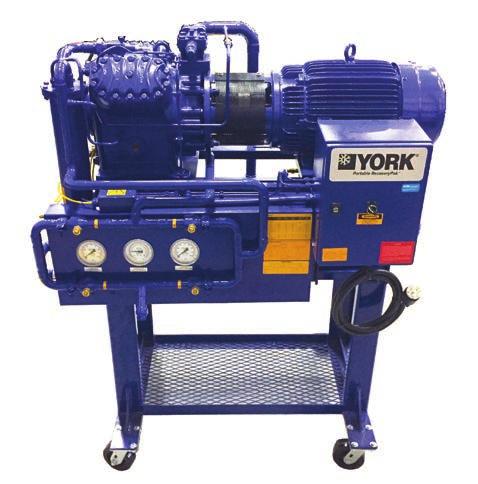

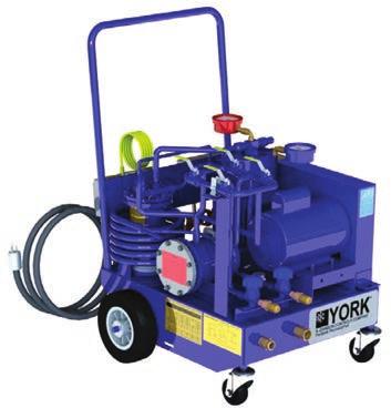
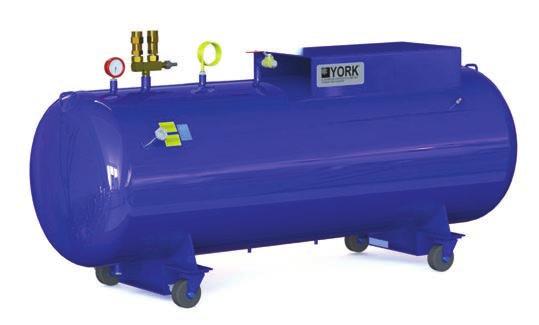
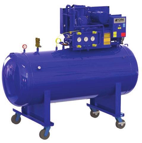
1 WATER-COOLED REFRIGERANT RECOVERY AND RECYCLING UNITS PORTABLE RECOVERY PAK EASYTANK RP 5400 RSR UNITS 1
2 IMPORTANT! READ BEFORE PROCEEDING! GENERAL SAFETY GUIDELINES This equipment is a relatively complicated apparatus. During installation, operation maintenance or service, individuals may be exposed to certain components or conditions including, but not limited to: refrigerants, materials under pressure, rotating components and both high and low voltage. Each of these items has the potential if misused or handled improperly, to cause bodily injury or death. It is the obligation and responsibility of operating/ service personnel to identify and recognize these inherent hazards, protect themselves, and proceed safely in completing their tasks. Failure to comply with any of these requirements could result in serious damage to the equipment and the property in which it is situated, as well as severe personal injury or death to themselves and people at the site. This document is intended for use by owner-authorized operating/service personnel. It is expected that these individuals possess independent training that will enable them to perform their assigned tasks properly and safely. It is essential that, prior to performing any task on this equipment, this individual shall have read and understood this document and any referenced materials. This individual shall also be familiar with and comply with all applicable governmental standards and regulations pertaining to the task in question. SAFETY SYMBOLS The following symbols are used in this document to alert the reader to specific situations:! DANGER Indicates a possible hazardous situation which will result in death or serious injury if proper care is not taken.! CAUTION Identifies a hazard which could lead to damage to the machine, damage to other equipment and/ or environmental pollu tion if proper care is not taken or instruc tions and are not followed.! Indicates a potentially hazardous situa tion which will result in possible injuries or damage to equipment if proper care is not taken.! Highlights additional information useful to the technician in completing the work being performed properly. WARNING NOTE! WARNING External wiring, unless specified as an optional connection in the manufacturer s product line, is not to be connected inside the control cabinet. Devices such as relays, switches, transducers and controls and any external wiring must not be installed inside the micro panel. All wiring must be in accor dance with Resolute Industrial published specifications and must be performed only by a qualified electrician. Resolute Industrial will NOT be responsible for damage/problems resulting from improper connections to the controls or application of improper control signals. Failure to follow this warn ing will void the manufacturer s warranty and cause serious damage to property or personal injury. 2
3 CHANGEABILITY OF THIS DOCUMENT In complying with Resolute Industrials policy for continuous product improvement, the information contained in this document is subject to change without notice. Resolute Industrial makes no commitment to update or provide current information automatically to the manual owner. Updated manuals, if applicable, can be obtained by contacting the nearest Resolute Industrial Service office or accessing the Resolute Industrial website at Operating/service personnel maintain responsibility for the applicability of these documents to the equipment. If there is any question regarding the applicability of these documents, the technician should verify whether the equipment has been modified and if current literature is available from the owner of the equipment prior to performing any work on the chiller. CHANGE BARS Revisions made to this document are indicated with a line along the left or right hand column in the area the revision was made. These revisions are to technical information and any other changes in spelling, grammar or formatting are not included. 3
4 4 THIS PAGE INTENTIONALLY LEFT BLANK.
5 TABLE OF CONTENTS SECTION 1 - INTRODUCTION...7 Inspection Damage Shortage...7 Safety Summary...7 Mechanical Specifications RSR Models...8 Mechanical Specifications Portable Recovery PAK...11 Mechanical Specifications Easy Tank...11 SECTION 2 - OPERATION...12 General...12 Prior to Starting Refrigerant Recovery...12 Operation of Refrigerant Storage/Recycle System...14 Liquid Transfer Refrigeration Unit to RSR Storage Vehicle...14 Detection and Removal of Non-Condensable Gases...16 Charging Refrigeration Unit with Refrigerant from RSR Unit...17 SECTION 3 DIAGRAMS...22 SECTION 4 - MAINTENANCE PROCEDURES...29 General...29 SECTION 5 - REPLACEMENT PARTS AND KITS...31 Compressor Replacement
6 LIST OF FIGURES FIGURE 1 - YORK RSR System Flow Diagram...14 FIGURE 2 - Wiring Diagram RSR FIGURE 3 - Wiring Diagram Easy PAK RP FIGURE 4 - Wiring Diagram RSR FIGURE 5 - Piping Diagram RSR-2222, FIGURE 6 - Piping Diagram Easy-Pak RP FIGURE 7 - Compressor Data Sheet Model 4G FIGURE 8 - Compressor Dimensions English 4G FIGURE 10 - Compressor Maintenance Instructions 4G FIGURE 11 - Photo, Compressor, Direct Drive 4G LIST OF TABLES TABLE 1 - RSR Specifications Standard...9 TABLE 2 - RSR Specifications Metric...9 TABLE 3 - Recovery PAK Specifications (Standard and Metric)...10 TABLE 4 - Standard Tank Options (Standard and Metric)...11 TABLE 5 - Settings for Pressure Safety Control Switches...12 TABLE 6 - Operation Settings...15 TABLE 7 - Final Vacuum/EPA Regulations...16 TABLE 8 - Pressure Difference for Determining Presence of Non-Condensable Gases...17 TABLE 9 - Vapor Pressure HFC-134a TABLE 10 - Vapor Pressure CFC TABLE 11 - Vapor Pressure (Metric (kpa) CFC-22 and CFC TABLE 12 - Vapor Pressure (Metric) HFC-134a...20 TABLE 13 - Vapor Pressure (Metric) CFC TABLE 14 - VAPOR PRESSURE (METRIC) CFC TABLE 16 - Compressor Refrigerating Capacity 4G.2: R134a, BTU/HR...37 TABLE 17 - Compressor Refrigerating Capacity 4G.2: R22, BTU/HR...37 TABLE 18 - SI Metric Conversion
7 SECTION 1 - INTRODUCTION 1 The YORK Refrigerant Recovery and Recycling units are designed to handle all of the major refrigerants used in air conditioning and refrigeration units. These include R-134a, R-500, R-502 and R-22. Refrigerant storage vessels are of a low pressure design for R-123 and a high pressure design for the remaining refrigerants. Two styles of units are available. One is a self-contained RSR ; the other is a combination of a Portable Recovery Pak complete with controls that is used in combination with an Easy Tank storage vessel complete with pressure safety controls and liquid float switch. INSPECTION DAMAGE SHORTAGE The unit shipment should be checked on arrival to see that all major pieces, boxes and crates are received. The unit should be checked on the trailer or rail car when received, before unloading, for visible signs of damage. Any damage or signs of possible damage should be reported to the transportation company immediately for their inspection. Also advise the Resolute Industrial Regional or District Office so a resolute industrial representative can assist in filing damage claims. RESOLUTE INDUSTRIAL WlLL NOT BE RESPONSIBLE FOR ANY DAMAGE IN SHIPMENT, OR AT JOB SITE, OR LOSS OF PARTS. If damage is found, Resolute Industrial must be notified and action must be taken to prevent further damage or deterioration of the machinery, i.e.: a slow refrigerant leak exposure of internal parts to atmosphere, etc. When received at the job site, all containers should be opened and contents checked against the packing list. Any material shortage should be reported to Resolute Industrial immediately. SAFETY SUMMARY Installation and servicing of air conditioning equipment and support equipment can be hazardous because of system pressures and the presence of dangerous voltages. Only trained and qualified service personnel should install, repair, or service such equipment. When using or servicing RSR units, observe precautions in the literature, as well as those on tags and labels attached to the equipment. Follow all safety codes. Wear glasses and work gloves when handling refrigerants. Before performing service or maintenance operations on this unit, turn off main power switch and disconnect power cord. Electrical shock could cause personal injury. Only the storage cylinder, interconnecting hose set, and filter driers supplied with the RSR unit may be used for hookup. Use of unspecified equipment could result in operator injury and/or release of refrigerant to the atmosphere. Avoid using an extension cord because the extension cord may overheat. If it is necessary to use an extension cord, the cord shall be #10 AWG minimum. Do not use this equipment near spilled or open containers of gasoline or other flammable products. This equipment should be used in a location with mechanical ventilation that provides at least four (4) air changes per hour. To avoid damaging the unit or the environment: The unit must be operated with the storage cylinder connected and valves fully open. Use only the hoses supplied with the unit. Shut off the filter drier valves before removing the filter drier. 7
8 MECHANICAL SPECIFICATIONS RSR MODELS The YORK Refrigerant/Recycling System is a selfcontained package consisting of a refrigerant compressor with oil separator, storage receiver, heater, water-cooled condenser, filter drier and necessary valves and hoses to remove, replace and distill CFC and HCFC Refrigerants. All necessary controls and safety devices are a permanent part of the system. The complete system is portable, being mounted on swivel casters with lock brakes. Refrigerant Compressor (High Pressure Units) The high pressure units for refrigerants HCFC-22, CFC-500, CFC-502 and HFC-134a feature a reciprocating compressor that is capable of pulling a vacuum to a level which is in accordance with EPA requirements (See Table 7 on page 16). Oil Separator and Heater Oil separator includes drain valve and 25 watt heater. Storage Receiver Several storage receiver sizes are available (See Table 1 on page 9). The vessel is a horizontal type with two sight glasses installed to check liquid level. The receiver is designed and stamped in accordance with the ASME Boiler and Pressure Vessel Code. The vessel is pitched toward the receiver drain to allow total removal of liquid. Valves and Hoses The unit has permanent-mounted ball valves to allow the unit to remove, replace, or distill refrigerant without having to break hoses to the chiller. Eight feet of heavy duty refrigerant hoses with flare fittings are included to allow connection to the chiller. Condenser The water-cooled condenser is a tube-in-tube design. The condenser is permanently mounted with refrigerant lines piped to the system. 3/4-inch hose bib connections are provided for field connection to the water supply. STORAGE RECEIVER The receivers are ASME certified. Each contains inlet and outlet valves and connections. Safety Devices A high-pressure switch is installed to protect the receiver and compressor against over pressurization. The relief device is per ASME specifications. Float switch cuts unit off when tank is 80% full of liquid refrigerant. Filter Drier The filter drier is permanently mounted on the system so that all gas entering or leaving the receiver will be filtered. The filter is a replaceable core type, capable of removing moisture to less than 50 ppm. Controls Mounted toggle switches are used to operate the unit and permit all safety devices to protect it. Gauges Unit-mounted gauges allow the technician to monitor suction and discharge pressure of the RSR system. 8
9 TABLE 1 - RSR SPECIFICATIONS STANDARD DESCRIPTION RSR-2222 RSR CFC-500 & 502 CFC-500 & 502 HCFC-22 HCFC-22 Refrigerant HFC-134a HFC-134a Refrigerant kg Refrigerant kg HCFC HCFC Refrigerant Storage CFC CFC Capacity (kg): CFC CFC % Full at 32 C HFC-134a 903 HFC-134a 2082 Working Pressure (kpa) Kilowatts V V-1-60 Standard Voltages 230V V-3-60 Plugs Included Yes 4 Prong Weight (kg) L x W x H* (mm) 2368 x 762 x x 1067 x 2286 Wheels Included Yes Optional Relief Valves (2) 3/4 FNPT (2) 1 FNPT ASME Approved Yes Yes Table 2 -- RSR SPECIFICATIONS -- METRIC DESCRIPTION RSR-2222 RSR-5445 CFC-500 & 502 CFC-500 & 502 HCFC-22 HCFC-22 Refrigerant HFC-134a HFC-134a Refrigerant Lbs Refrigerant Lbs HCFC HCFC Refrigerant Storage CFC CFC Capacity (Lbs.) CFC CFC % Full at 90 F HFC-134a 1992 HFC-134a 4635 Working Pressure (PSI) Horsepower V V-1-60 Standard Voltages 230V V-3-60 Plugs Included Yes 4 Prong Weight (Lbs.) L x W x H* (Inches) 93-1/4 x 30 x 60-1/8 112 x 42 x 90 Wheels Included Yes Optional Relief Valves (2) 3/4 FNPT (2) 1 FNPT ASME Approved Yes Yes *Wheels add 330 mm to overall height dimension of RSR-4436 and
10 MECHANICAL SPECIFICATIONS PORTABLE RECOVERY PAK Valves and Hoses The unit includes one input/one output refrigerant valves, and two refrigerant hoses, 8 long. Filter It includes replaceable, catch-all type filters with singlecore, 48 cubic inches (786 Ccm). Refrigerant Compressor (High Pressure Units The high pressure units for refrigerants HCFC-22, CFC-500, CFC-502 and HFC-134a feature s a reciprocating compressor that is capable of pulling a vacuum to a level which is in accordance with EPA regulations. (See Table 7 on page 16.) Condenser The water-cooled condenser is a tube-in-tube design. The condenser is permanently mounted with refrigerrant lines piped to the system. 3/4-inch hose bib connections are provided for field connection to the water supply. Oil Separator and Heater Oil separator includes a drain valve and 25 watt heater. Controls An on/off switch; electrical cord and plug are provided. Safeties Unit safeties include high pressure cutoff (adjustable), and vacuum cutoff (adjustable). With a YORK refrigerant EasyTank, integral safeties include heater cut- off (low pressure tanks only) pressure relief valve and a liquid level switch. The pressure relief valves meet ASME specifications. Tanks Two standard EasyTank receivers are available, from 1992 to 4895 pound capacities. Features The unit has a solid frame construction. The unit is equipped with four heavy duty wheels for mobility. The size and shipping weights are provided in (Table 3 on page 10). on page 10). TABLE 3 - RECOVERY PAK SPECIFICATIONS (STANDARD AND METRIC) Model DESCRIPTION RP-2200 RP-4400 CFC- 500 & 502 CFC-500 & 502 HCFC-22 HCFC-22 Refrigerant HFC-134a HFC-134a Working PSIG Pressure kpa HP Power KW V-1-60 Standard 208V-1-60 Voltages 230V V-3-60 Plugs Included Yes 4 Prong Lbs Weight Kg Inches 24 x 24 x x 29 x 66 L x W x H mm 610 x 610 x x 737 x 1676 Wheels Included Yes Yes 10
11 Gauges Unit mounted gauges allow the monitoring of the suction and discharge pressure of the RSR system. MECHANICAL SPECIFICATIONS EASY TANK Safeties High-pressure tanks use relief valves and liquid level safeties*. *Float switch shuts off recovery unit when tank becomes 80% full of liquid refrigerant. Rating The tanks are ASME certified. All tanks contain inlet and outlet valves and connections (See Table 4 on page 11). Gauges Sight glasses and pressure gauges are included. Wheels Standard wheels are included for tanks under 3000 pounds (1361 kg); custom wheels available for larger sizes. Custom Tanks Custom-made tanks are also available from 50 pounds (22.7 kg) storage capacity to as large as required for high pressure refrigerants. Custom components, controls, safeties, and wheels are available. Optional Clean Out Port An ASME coded access port may be added as an option. The port opening is approximately 11 x 19 (279 mm x 482 mm). TABLE 4 - STANDARD TANK OPTIONS (STANDARD AND METRIC) REFRIGERANT STORAGE CAPACITY: 80% FULL AT 90 F (32 C) DIAMETER X LENGTH APPROXIMATE SHIPING WEIGHT MODEL REFRIGERANT LBS. KG INCHES MM LBS. KG HCFC x 93-1/4 702 x CFC x 93-1/4 702 x RT CFC x 93-1/4 702 x HFC-134a x 93-1/4 702 x HCFC x x CFC x x RT CFC x x HFC-134a x x
12 SECTION 2 - OPERATION 2 GENERAL The function of a Refrigerant Recovery/Recycling Unit (RSR) is to remove and store refrigerant from any machine using the refrigeration cycle and CFC or HCFC refrigerants. The refrigerants must be removed from the refrigerant circuit before opening any part of the unit for maintenance or repairs. Federal law prohibits the venting of refrigerant to the atmosphere. The RSR is connected to the refrigeration unit by means of hoses supplied with the RSR. The RSR compressor develops a pressure differential between the RSR and the refrigeration unit so that liquid refrigerant is forced into a storage vessel used in conjunction with the RSR. The RSR is equipped with a water cooled condenser that is used to condense the refrigerant vapor remaining in the refrigeration unit after the liquid refrigerant has been removed. For this duty, the RSR compressor pumps the remaining vapor through the condenser and the resulting liquid refrigerant flows into the storage vessel. After the refrigeration unit has been repaired, the process is reversed so that refrigerant is pumped back into the refrigeration unit. PRIOR TO STARTING REFRIGERANT RECOVERY Set Pressure Safety Control A high/low pressure safety control is wired in the mo- tor control circuit. The pressure settings are adjustable to conform to the design working pressure of the RSR storage vessel and the upper limit for satisfactory performance of the RSR condenser and compressor for the refrigerant being recovered.! NOTE Prior to starting the RSR unit, the pres sure control must be set to the high and low pressure values shown in Table 5 on page 12. Check Oil Level RSR Compressor (High Pressure Units) The oil level should be checked in the sight glass located in the RSR compressor crankcase.! WARNING A shortage of oil will result in the failure of the RSR compressor. The oil level should be 1/2 to 3/4 from the bottom of the sight glass when the RSR compressor is not running. Continued on page 13. TABLE 5 - SETTINGS FOR PRESSURE SAFETY CONTROL SWITCHES REFRIGERANT HIGH PRESSURE CUT-OUT LOW PRESSURE HIGH PRESSURE CUT-IN LOW PRESSURE PSIG KPA IN HG KPA PSIG IN KG KPA HFC-134a Manual Reset CFC Manual Reset CFC Manual Reset HCFC Manual Reset
13 All units, except where Refrigerant 134a is used, come factory charged with YORK Type C oil. Only this type of oil should be used when adding oil with the exception where R-134a is used in the refrigeration unit. The Ester based oil is used in conjunction with R-134a. Consult the manufacturer s recommendations for oil to be used in the RSR compressor if R-134a is used in the refrigeration system. It is recommended that an RSR unit be dedicated for use in recovering only R-134a. Otherwise the oil in the RSR compressor and oil separator will have to be changed when changing from other refrigerants to R-134a and when changing back from R-134a to other refrigerants. See the SECTION 4 - MAINTENANCE PROCEDURES of this manual for the correct procedure for adding and removing oil from the RSR unit compressor and oil separator. Filter Dryer Replacement Element The RSR unit contains a filter dryer that removes moisture, acids, as well as solid particles from the refrigerant that is being recovered. The filter dryer contains a removable element (Sporlan #RC 4864) that must be in place before the unit is used. The filter/dryer element must also be changed when: 1. Changing the type of refrigerant being recovered. 2. When the liquid sight glass indicator shows that excessive moisture is in the refrigerant. 3. After recovering refrigerant from a refrigeration unit that has had a motor burnout. If the refrigeration unit, from which the refrigerant is being recovered, has experienced a hermetic compressor motor burn out, or if the liquid sight glass/ moisture indicator shows excessive moisture in the refrigerant, a filter/dryer (Sporlan C-415) should be inserted at the end of the RSR liquid refrigerant hose, where it connects to the refrigeration unit liquid connection. Before the refrigeration unit is recharged, the valve at the end of the liquid hose and on the refrigeration unit (at the opposite end of the filter dryer) should be closed. Remove the filter dryer and replace it with a new filter dryer with the arrow pointing in the direction of the refrigeration unit.! NOTE The arrow indicating direction of flow should point toward the RSR unit when liquid refrigerant moves from the refrigeration unit to the RSR storage vessel. See SECTION 4 - MAINTENANCE PROCEDURES for specific instructions for changing the filter/dryer element. Connecting Hoses The refrigerant hoses, furnished with the RSR unit, are connected to the evaporator and condenser of the refrigeration. unit as shown in the schematic diagram shown in Figure 1 on page 14. A third hose, used with the portable unit only, is connected between the valve on the top of the storage vessel and the refrigerant connection on the condenser of the portable RSR unit. 4. After the RSR unit has been run for 100 hours. 13

14 Only the dedicated storage vessel and interconnecting hose set supplied with the RSR unit can be used for the hookup.! WARNING Use of Unspecified Equipment Could Result in Personal Injury and Release of Refrigerant to the Atmosphere. When using the Portable Recovery Pak, it is mandatory that the EasyTank, manufactured by Resolute Industrial, be used as the storage vessel. These contain the proper pressure relief valves, liquid level float switch and matching interconnecting wiring for the safety switches. In order for the Portable Recovery Pak to operate, the interconnecting safety wiring must be plugged into the matching socket. Shipping Charge When the unit is shipped from the factory, a holding charge of dry nitrogen is placed in the storage vessel under a pressure of approximately 5 psig. Prior to first using the RSR unit, the pressure should be relieved to the atmosphere and the vessel evacuated with a vacuum pump to a vacuum of 29 inches of mercury. Evacuate using gas connection (connection between valves 1 & 2), open valves 1, 2, 3, & 4 during evacuation close valve 5. (See Figure 1 on page 14) FIGURE 1 - YORK RSR SYSTEM FLOW DIAGRA OPERATION OF REFRIGERANT STORAGE/ RECYCLE SYSTEM Liquid Transfer Refrigeration Unit to RSR Storage Vehicle This method is recommended for the initial phase of refrigerant recovery. (See Figure 1 on page 14) To bleed air from the connecting liquid refrigerant hose: 1. With valve 5 closed, crack valve 6 at the evaporator. 2. Slowly open refrigerant hose connection at 5 until a very small amount of refrigerant exists at the hose connection. (Make sure unit is above 0 psig if not, do not use this step.) 3. Re-tighten hose fitting at valve 5. To bleed air from the remaining refrigerant hose: 1. Close valves 1 and 2. fold and retighten hose fitting as above. (Make 2. Crack valve Bleed refrigerant from hose connection at manifold and re-tighten hose fitting as above. (Make sure unit is above 0 psig if not, do not use this step.) 14
15 Set the valves and pumps as shown in the first column of Table 6 on page 15. Start the RSR unit by switching the toggle switch on the control box to the ON position. When the RSR unit is started, the compressor reduces the pressure in the storage vessel. The discharge side of the compressor pressurizes the refrigeration unit through the connection to the condenser. The resulting pressure differential forces the liquid refrigerant from the refrigeration unit into the RSR storage vessel. The transfer of liquid is complete when the level in the RSR storage vessel, as observed through the sight glasses, ceases to rise. Close valve 5 and move the RSR toggle switch to the OFF position. Proceed to the Gas Pump Out. TABLE 6 - OPERATION SETTINGS TO REMOVE LIQUID TO REMOVE GAS FROM CONTROL FROM CHILLER CHILLER RSR SYSTEM TO REMOVE OIL FROM RERIGERANT TO RECHARGE CHILLER STEP 1 GAS OFF STEP 2 LIQUID CHARGE Valve 1 Open Closed Open Closed Valve 2 Closed Open Closed 1 & 4 or Open Valve 3 Open Closed Open Open 2 & 3 Closed Valve 4 Closed Open Closed Open Valve 5 Open Closed Closed Closed Open Compressor On On On Off On Water to Condenser Off On Off Off On Heater Off Off On Off On CHILLER/AIR CONDITIONER Valve 6 Open Closed Closed Closed Open Valve 7 Open Open Open Open Open Chiller Water Pump Off On On On On Either Condenser One Water Pump Off Off On On On 15
16 Gas Pump Out Refrigeration Unit To Rsr Storage Vessel After the liquid refrigerant has been removed from the refrigerant unit, as previously described, the following procedure is used to remove the remaining refrigerant gas. Set the valves and pumps as shown in column 2 of Table 6 on page 15. Start the RSR unit by turning the toggle switch to the ON position.! On units RSR-2222 and RP-2200 close compressor suction service valve so that suction pressure does not exceed 70 psig. NOTE The RSR unit draws refrigerant vapor from the refrigeration unit and condenses same in the RSR water cooled condenser. The liquefied refrigerant flows to RSR storage vessel. During the evacuation process, valve! 6 should remain open to evacuate the refrigerant hose between valves 6 and 5. When the system being evacuated reaches the aforementioned NOTE vacuum, valve 6 should be closed to seal off the hose. Valve 7 should be closed prior to turning the RSR unit off to evacuate the remaining refrigerant hose. After the hoses have been evacuated and valves 6 and 7 closed, the RSR unit can be shut off but the hoses must remain in place. After a waiting period of 5 minutes, the pressure in the refrigeration unit is to be checked. If procedure must be repeated until a pressure rise is not detected after a five-minute waiting period. The pressure has risen due to residual refrigerant remaining in the refrigeration unit, the Gas Pump Out. WHEN EVACUATING! REFRIGERATION UNITS WITH LIQUID CHILLER AND/OR WATER COOLED CONDENSERS During the pump out procedure, while CAUTION any remaining liquid refrigerant is in contact with unit water tubes, care must be taken to prevent the unit saturation pressure/temperature from dropping below the freezing temperature of the water or brine. The operation should continue until a vacuum of the value shown in Table 6 on page 15 exists for the specified type of refrigeration unit being evacuated. 16
17 TABLE 7 - FINAL VACUUM/EPA REGULATIIONS 2 DESCRIPTION HCFC-22 unit containing less than 200 Lbs. /91 kg of refrigerant HCFC-22 unit containing more than 200 Lbs./91 kg of refrigerant Other high pressure units containing less than 200 Lbs. /91kg of refrigerant Other high pressure units containing more than 200 Lbs./91 kg of refrigerant FINAL VACUUM IN. HG (KPA) 0 (0) 10 (33.9) 10 (33.9) 15 (51) DETECTION AND REMOVAL OF NON-CONDENSIBLE GASES After the RSR unit containing the stored refrigerant has equalized such that the machine and stored refrigerant are at the same temperature as the surrounding ambient temperature, the refrigerant can be checked for non-condensible gases. If the pressure in the storage vessel, as read on the compressor discharge gauge, exceeds the saturation pressure of the refrigerant at the ambient temperature by the amount shown in Table 8 on page 17, there is a need to vent the non-condensible gases from the Schrader type valve located on the top of the storage vessel for a period of fifteen seconds. The procedure should be repeated until the saturation pressure in the storage vessel is within the pressure range shown in Table 8 on page 17 for the given refrigerant. The storage vessel and contained refrigerant should be allowed to equalize to ambient temperature between venting s. When the refrigerant in the storage vessel reaches a stable temperature equal to the surrounding ambient air temperature the pressure in the storage vessel, read on the compressor discharge gauge, should be the same as the saturation pressure for the ambient temperature. If the pressure reading is higher by the above values, or more, the storage vessel should be purged of non-condensible. 17
18 18 TABLE 8 - PRESSURE DIFFERENCE FOR DETERMINING PRESENCE OF NON-CONDENSIBLE GASES DIFFERENCE BETWEEN GAUGE READING AND SATURATED PRESSURE REFRIGERANT PSIG KPA HFC-134a CFC HCFC CFC CHARGING REFRIGERATION UNIT WITH CHARGING REFRIGERATION UNIT WITH REFRIGERANT FROM RSR UNIT Gas Charging When it is time to transfer the refrigerant from the RSR to the refrigeration unit, the latter must first be charged with gas. This is particularly true of refrigeration units containing liquid coolers and/or water cooled condensers. If liquid refrigerant is charged in the unit when the unit pressure is lower than the saturation pressure equivalent to 32 F (0 C), the water tubes can freeze and burst even though water is being pumped through the tubes. Set the water flow and valves as shown in column 4 Table 6 on page 15. When the valves are set, refrigerant gas will flow into the refrigeration unit because of the higher pressure in the RSR. The RSR compressor does not have to run during gas charging. When the refrigeration unit pressure is above the saturation pressure equivalent to 32 F (0 C) (Table 8) or when the pressure has equalized, close all of the valves. Charging with Liquid Refrigerant Set the valves and pumps as indicated in column 5 of Table 6 on page 15. Turn the toggle switch on the RSR to the ON position. Refrigerant vapor will be pulled off of the top of the refrigeration unit condenser, raised to a higher pressure by the RSR compressor, condensed to liquid in the RSR condenser, and then returned to the refrigeration unit as a liquid. The level of liquid in the storage vessel can be observed through the sight glasses in the vessel. When the liquid has been exhausted from the storage vessel, close valves 6 and 7 and simultaneously shut OFF the RSR toggle switch. Removal of Refrigerant from Hoses and StorageVessel Before removing the hoses between the RSR and the refrigeration unit, open valves 1 and 3 on the manifold and close valves 2 and 4. Start the RSR compressor and open valve 7 simultaneously. Valve 5 should be open and valve 6 closed. Run the RSR compressor until a vacuum of at least 29 in. Hg. exists in the storage vessel. At this point, close valve 7 and simultaneously move the RSR toggle switch to the OFF position. Close manifold valves 1, 2, 3, and 4, as well as valve 5. The hose valves can then be closed and the hoses removed from the refrigeration unit. TABLE 9 - VAPOR PRESSURE CFC-11, CFC-12, CFC-22 AND CFC-500 TEMP. ( F) CFC VAPOR PRESSURE* CFC
19 TABLE 9 - VAPOR PRESSURE CFC-11, CFC-12, CFC-22 AND CFC-500 (CONT D) TABLE 10 - VAPOR PRESSURE HFC-134A TEMP. ( F) CFC-22 VAPOR PRESSURE* CFC-500 VAPOR PRESSURE (PSIG)* *Vapor pressures are shown as PSIG. Screened figures are shown as inches of mercury (HG) vacuum. TEMP. ( F) HFC-134A *Vapor pressures are shown as PSIG. Screened figures are shown as inches of mercury vacuum. 19
20 TABLE 11 - VAPOR PRESSURE CFC-114 AND CFC-502 TEMP. ( F) TEMP. ( F) VAPOR PRESSURE (PSIG)* CFC TABLE 11 - VAPOR PRESSURE CFC-114 AND CFC-502 (CONT'D) VAPOR TEMP. ( F) PRESSURE (PSIG)* CFC *Vapor pressures are shown as PSIG. Screened figures are shown as inches of mercury (HG) vacuum
21 TABLE 12 - VAPOR PRESSURE (METRIC (KPA) CFC-22 AND CFC-500 TEMP. VAPOR PRESSURE (KPA)* ( C) CFC-22 CFC TABLE 12 - VAPOR PRESSURE (METRIC (KPA) CFC-11, CFC-12, CFC-22 AND CFC-500 (CONT'D) TEMP. ( C) VAPOR PRESSURE (KPA)* CFC-22 CFC *Vapor pressures are shown as kpa. Screened figures are shown as kpa of mercury vacuum. TABLE 13 - VAPOR PRESSURE (METRIC) HFC-134A TEMP. ( C) VAPOR PRESSURE (KPA)* HFC-134A *Vapor pressures 65.6 are shown as kpa. Screened 1823figures are shown as kpa of mercury vacuum. 21
22 TABLE 14 - VAPOR PRESSURE (METRIC) CFC-502 TEMP. ( C) VAPOR PRESSURE (KPA)* CFC TABLE 14 - VAPOR PRESSURE (METRIC) CFC-502 (CONT'D) TEMP. ( C) VAPOR PRESSURE (KPA)* CFC *Vapor pressures are shown as kpa. Screened figures are shown as kpa of mercury (HG) vacuum. 22

23 SECTION 3 - DIAGRAMS 3 LEGEND SW Sw itch, On-Off (Compressor Motor) HP-LP Switch, Pressure, Combination Hi-LO LS Switch, Liquid Level 1-R Relay, Float Switch, N.O. contact 2-R Relay, Motor Circuit, N.O. contact HTR Heater, Oil Separator FIGURE 2 - WIRING DIAGRAM RSR

24 FIGURE 3 - WIRING DIAGRAM EASY PAK RP -2200! NOTE *Interlock Receptacle will not allow EASY PAK Compressor to operate unless liquid level switch LS is in the electrical control circuit. SW HP-LP LS LSR HTR Legend Switch, On-Off, Motor Switch, Pressure, Combination Hi-Lo Control Switch, Liquid Level Relay, N.O. contact Heater, Oil Separator (25 watt) 24
 HP-LP Switch, Pressure, Combination Hi-Lo Control LS Switch, Liquid Level 1-R Relay, Liquid Level, N.O. contact M Contactor, Compressor Motor LD17565 FIGURE 4 - WIRING DIAGRAM RSR-5445 25")
25 Supplied with 8' flexible cord and interlocking plug for liquid level switch circuit on refrigerant storage tank. Legend SW Switch, On-Off (Compressor) HP-LP Switch, Pressure, Combination Hi-Lo Control LS Switch, Liquid Level 1-R Relay, Liquid Level, N.O. contact M Contactor, Compressor Motor LD17565 FIGURE 4 - WIRING DIAGRAM RSR
 Core 20 Switch-Compressor 3 Compressor Pulley 11 Moisture Indicator Switch-Heater Belt 12 High Pressure Vessel 21 Refrigerant Hoses Base for Unit 13 Relief Assembly 22 Valve 4 Belt")
26 4 LD17568 LEGEND ITEM DESCRIPTION ITEM DESCRIPTION ITEM DESCRIPTION 1 Compressor 8 Condenser 18 Relief Valve 2 Motor 9 Ball Valves 19 Pressure Switch Drive Package: Filter Dryer: Junction Box: 10 Motor Pulley (1) Core 20 Switch-Compressor 3 Compressor Pulley 11 Moisture Indicator Switch-Heater Belt 12 High Pressure Vessel 21 Refrigerant Hoses Base for Unit 13 Relief Assembly 22 Valve 4 Belt Guard 14 Sight Glass 23 Power Wire 5 Gauges 15 Casters 6 Oil Separation 16 Purge Valve 7 Heater 17 Float Switch 26

27 LD17569 LEGEND ITEM DESCRIPTION ITEM DESCRIPTION ITEM DESCRIPTION 1 Vacuum Pump 9 Ball Valves 17 Power Wire 2 Motor 10 Filter Dryer 18 Customer Service Valve 3 Drive Package: 11 Moisture Indicator Belt Guard: 12 Wheels 4 Pulleys: Compressor 13 Relief Valve Pulleys: Motor 14 Pressure Control: 5 Gauges Junction Box 6 Oil Separator 15 Switches 7 Heater Oil Separator Remote Pressure Interlock 8 Condenser 16 Refrigerant Hoses FIGURE 6 - PIPING DIAGRAM EASY-PAK RP
28 28 THIS PAGE INTENTIONALLY LEFT BLANK.
29 SECTION 4 - MAINTENANCE PROCEDURES 4 GENERAL Replacement of Filter Dryer Element 1. Unplug the RSR power cord. 2. Close valves 1, 2, 3 and 4 in the manifold (See Figure 1 on page 14) and the compressor discharge valve. 3. Remember that the system is under pressure and safety glasses and gloves should be worn during this operation. 4. Slowly turn each of the bolts, holding the end plate on the canister, open one or two turns. Allow the reduction of pressure within the canister before completely removing the end plate. 5. Remove the old filter core from the canister and remove the O ring gasket from the end plate. Wipe the inside of the canister and the end plate clean with a clean cloth. 6. Replace the O ring gasket with a new one after wiping it with a coating of the same type of oil being used in the compressor. 7. Remove the new filter/dryer element (Sporlan # RC 4864) from the hermetically sealed wrapper. The new element must be placed in the canister immediately since it would otherwise absorb moisture from the surrounding air. 8. Replace the end plate and bolt in place using an alternate pattern for tightening the bolts. 9. Prior to opening the compressor discharge valve, crack valve number 3 of the manifold and slightly break the flare connection in the tubing where it enters the compressor discharge. Allow the air to be purged from the filter dryer and then tighten the flare fitting and open the compressor discharge valve. Belts The Refrigerant Recovery/Recycle Unit (RSR) compressor drive belt should be checked frequently for excessive wear and tightness. If belt is in bad condition, it should be replaced immediately. Correct belt tension prevents the motor pulley from slipping, keeping the transfer unit operating at peak efficiency. The belt tension adjustment should be made so the belt is taut, but not too taut to create excessive bearing loads. Due to the pulsating load created by the compressor, the belt tension must be greater than for a normal, steady load. Belt tension can be accurately determined with the use of a belt tension gauge which gives a direct reading of belt load as determined by the deflection. A tension of 100lbs is considered to be the normal belt tension. After 36 to 48 hours of operating time, the belt should 4 stretch to a normal operating point and a further check for proper tension should be made. Good alignment and belt tension are important to insure long belt life, quiet operation and to maintain top system performance. Pulley Alignment A very important factor in compressor operation is correct pulley alignment. The compressor pulley must be in perfect alignment with the motor pulley and it is important that the shaft key is in place on the shaft and the pulley bolt drawn tight, when installing a pulley. The pulley alignment may be checked by holding a 1/2 rod 2 or 3 feet long firmly in the V groove of the compressor drive pulley wheel and making sure the rod falls squarely in the motor pulley grooves. A further check may be made by seeing that the belt, as it goes from pulley to pulley, comes off the pulley grooves perfectly straight and that there are no side-way bends in the belt, as it approaches or leaves the pulleys. Pulleys and belts must be clean and free of oil. Adding or Changing Oil (High Pressure Units) When the RSR is not running and the refrigerant pressures have equalized, the oil should be 1/2 to 3/4 of the height of the sight glass in the compressor oil sump. To add oil: 1. Unplug the power cord. 2. Close the compressor discharge and suction valves and manifold valves 1 and 4 (See Figure 1 on page 14) and vent the pressure from the compressor. Using an oil pump, open the drain valve on the compressor sump, and pump oil into the compressor until it is at the proper level. 3. The type of oil should be the same as that used in the refrigeration unit being serviced. 29
30 To change oil: 1. Follow steps one and two above. 2. After the refrigerant pressure has been relieved to atmospheric pressure, the oil is drained from the compressor oil sump through the sump drain valve. When the oil has drained, immediately close the valve so that moisture and air do not enter the compressor. 3. To remove the oil from the oil separator, the flanged top must be unbolted and removed. First, however, the flared refrigerant tube connections must be removed from the top of the oil separator. Be sure to only slightly open the flare fittings initially to make certain the refrigerant pressure has first been relieved. Open the valve at the bottom of the separator and drain the oil. 4. Clean the interior with a clean cloth and removeand clean the screen filter. 5. After replacing the screen filter, replace the top of the oil separator. 6. Before replacing the refrigerant and oil return tubes, use a pump to pump ten fluid ounces of oil into the separator. 7. Connect the oil pump to the compressor oil drain valve open the valve pump ten fluid ounces of oil into the compressor sump and close the drain valve. 8. After allowing several minutes for the oil level to stabilize, check to see that the oil level is 1/2 to 3/4 above the bottom of the sight glass. If not, adjust accordingly. 9. It must be emphasized that the oil used in the high pressure RSR compressor is the same as that used in the refrigeration unit being serviced. Normally YORK Type C Refrigeration oil is used except in units charged with R-134a. An Ester base oil must be used with this refrigerant. 10. Open the compressor suction and discharge valves. And next, crack the flare fitting on the tube that connects the valve manifold to the oil separator to purge air from the compressor and oil separator. 11. Open the manifold valves as required for the next recovery operation. Compressor Prior to servicing the compressor: 1. Make sure the power is disconnected. 2. Close Suction and discharge service valves. 3. Bleed refrigerant from the compressor to relieve the air from the compressor and oil separator pres- sure within. Pressure should be 5 psig or less prior to opening the compressor. Servicing Compressor Care must be taken when servicing the compressor not to mar, nick or scratch any of the parts. All machined surfaces must be free of nicks or burrs to ensure a proper fit and seating of gaskets. When replacing parts and reassembly, the specified torque requirements should not be exceeded. Bolts should all be run in until bolt heads make contact. Final tightening should be in a sequence so that bolts diagonally opposite are tightened and all drawn evenly to the specified torque. One of the most important factors in servicing compressors is cleanliness. Extreme care should be taken to keep foreign material from entering the compressor when it is open. All old gaskets should be replaced. Any old gasket material adhering to the parts should be carefully removed. Reusable parts should be cleaned in a solvent. 30
31 Checking Compressor for Performance If the compressor appears not to perform properly, the following checks should be made: 1. Allow the suction pressure to build up to a minimum of 30 psig. Thoroughly check the compressor and all refrigerant holding components for leaks. 2. If no leaks are found, close the suction service valve and run compressor until compressor suction pressure is 0 psig. 3. Stop compressor. Observe discharge pressure and if it remains constant the discharge valves of the valve assembly are holding properly. If pressure drops more than 5 Ibs. (34.5 kpa) in one minute, this indicates the discharge valves of the valve assembly are leaking and should be replaced. If in doubt as to whether the discharge valves leak turn the compressor over by hand. If pressure rises and falls with each revolution this will confirm the discharge valve leak. 4. If the discharge valves are holding then check suction valves of the valve assembly. 5. Back seat (open) the discharge service valve, with the service suction valve closed, run compressor until a vacuum of 25 (85 kpa) is reached. Failure of a compressor to reach 25 (85 kpa) vacuum indicates leaky suction valves. All compressors should pump a 25 (85 kpa) vacuum against normal head pressures. COMPRESSOR MODEL 3 (iii) Servicing of Shaft Seal When servicing the shaft seal, extreme care must be taken when removing or installing the parts to prevent damage to the lapped surfaces and other seal parts. The portion of the shaft upon which the seal fits must be free of scratches, burrs and dirt, and the seal housing cavity must be clean. Removal of Seal Assembly 1. Remove the sheave and key from the shaft. 2. Remove the seal retainer plate bolts and gently remove the seal plate. 3. Remove the seal assembly from the shaft. 4. Clean all parts to be reused. 31
32 Installation of Seal Assembly 1. Check all surfaces to make certain nicks and burrs do not exist. 2. Wash all parts of the seal assembly in clean oil of the same type being used in refrigeration unit being serviced. 3. Push the seal assembly onto the shaft. Move the seal assembly in and out on the shaft to ensure a good seal. 4. Place a very light film of oil on the matching metal faces where the O ring is to be placed. Place the O ring in the groove. 5. Place the seal retainer plate in position with the polished surface facing the compressor. Turn the bolts in evenly while rotating the shaft, making sure that the clearance between the shaft and the hole in the retainer plate is the same all around the circumference. If clearance is not the same all around, gently tap the seal retainer plate until it is so. Tighten bolts diagonally opposite to the required torque (See Table 16 on page 35). Servicing Valve Plate and Head In removing the head, extra care should be taken not to damage the sealing surfaces. Removal of Head and Valve (See Figure 9 on page 33) 1. Remove the four bolts (15) from cylinder head.! NOTE The four bolts removed are longer in length than the remaining head bolts. 2. Remove the remaining bolts in the cylinder head and remove the valve plate (3), and cylinder head from the crankcase by tapping lightly under the ears which extend from the valve plate. If the head and valve plate adhere, hold the head and tap the valve plate ears away from the head with a soft hammer. Do not hit or tap the head to separate the head and valve plate because damage to the head may result. 3. All gasket material adhering to the head, valve plate, or cylinder, should be carefully removed in such a manner that the machined sealing surfaces are not scratched or nicked. Installation of Head and Valve Plate 1. Apply a thin film of clean YORK Refrigeration oil on the area of the crankcase to be covered by the cylinder gasket. Place the cylinder gasket in position on the cylinder so the dowel pins in the crankcase go through the dowel pin holes in the cylinder gasket. 2. Apply a thin film of clean YORK Refrigeration oil to the top and bottom valve plate area to be covered by gaskets. Place the valve plate in position on the cylinder gasket so the discharge valve assemblies (i.e. the smaller diameter assemblies with the retainer over the valve reed) are facing up and the locating dowel pins go through the dowel pin holes in the valve plate. 3. Place the head gasket (4) in position on the valve plate (3) so the dowel pins go through the dowel pin holes in the gasket. 4. Apply a light film of clean YORK Refrigeration oil on the machined surface of the cylinder head which matches the head gasket. Place the head on the cylinder head gasket so the dowel pins go into the dowel pin holes in the head. 5. Apply a thin film of clean YORK Refrigeration oil to the service valve flanges on the head and on the service valve flange. Place a service valve gasket in position on the cylinder head service valve flanges. Place the service valve in position on the proper service valve ports and insert the longer bolts through the service valve mounting pads, the head, end valve plate and in the crankcase. 6. Insert the remaining head bolts and run in all the bolts so the bolt heads make contact. Tighten the head and service valve bolts to the required torque, by tightening the service bolts first. Then tighten the remaining in a sequence so bolts diagonally opposite each other are evenly drawn to the specified torque. 32
33 Installation of Head and Valve Plate 1. Apply a thin film of clean YORK Refrigeration oil on the area of the crankcase to be covered by the cylinder gasket. Place the cylinder gasket in position on the cylinder so the dowel pins in the crankcase go through the dowel pin holes in the cylinder gasket. 2. Apply a thin film of clean YORK Refrigeration oil to the top and bottom valve plate area to be covered by gaskets. Place the valve plate in position on the cylinder gasket so the discharge valve assemblies (i.e. the smaller diameter assemblies with the retainer over the valve reed) are facing up and the locating dowel pins go through the dowel pin holes in the valve plate. 3. Place the head gasket (4) in position on the valve plate (3) so the dowel pins go through the dowel pin holes in the gasket. 4. Apply a light film of clean YORK Refrigeration oil on the machined surface of the cylinder head which matches the head gasket. Place the head on the cylinder head gasket so the dowel pins go into the dowel pin holes in the head. 5. Apply a thin film of clean YORK Refrigeration oil to the service valve flanges on the head and on the service valve flange. Place a service valve gasket in position on the cylinder head service valve flanges. Place the service valve in position on the proper service valve ports and insert the longer bolts through the service valve mounting pads, the head, end valve plate and in the crankcase. 6. Insert the remaining head bolts and run in all the bolts so the bolt heads make contact. Tighten the head and service valve bolts to the required torque, by tightening the service bolts first. Then tighten the remaining in a sequence so bolts diagonally opposite each other are evenly drawn to the specified torque. 33
34 SECTION 5 - REPLACEMENT PARTS AND KITS 5 Technical Data Technical Data Displacement (1450 RPM 50Hz) 84,5 m³/h Displacement (1750 RPM 60Hz) 101,98 m³/h No. of cylinder x bore x stroke 4 x 75 mm x 55 mm Weight 192 kg Max. pressure (LP/HP) 19 / 28 bar Connection suction line 54 mm - 2 1/8 Connection discharge line 28 mm - 1 1/8 Connection cooling water R 3/4 Oil type R134a/ R407C/R404A/R507A/R407A/R407F tc<55 C: BSE32 / tc>55 C: BSE55 (Option) Oil type R22 (R12/R502) B5.2 (Standard) Oil type R290/R1270 SHC226E (Standard) Motor data Motor voltage (more on request) V PW-3-50Hz Max operating current 37.0 A Winding ratio 50/50 Starting current (Rotor locked) 97.0 A Y / A YY Max. Power input 22,1 kw Extent of delivery (Standard) Motor protection SE-B2 Enclosure class IP54 (Standard), IP66 (Option) Vibration dampers Standard Oil charge 4,50 dm³ Available Options Discharge gas temperature sensor Option Start unloading Option Capacity control % (Option) Additional fan Option Water-cooled cylinder heads Option CIC System Option Oil service valve Option Crankcase heater 140 W (Option) Oil pressure monitoring MP54 (Option), Delta-PII (Option, not for R290/R1270) Sound measurement Sound power level (-10 C / 45 C) 81,0 50Hz Sound power level (-35 C / 40 C) 86,5 50Hz Sound pressure 1m (-10 C / 45 C) 73,0 50Hz Sound pressure 1m (-35 C / 40 C) 78,5 50H FIGURE 7 - COMPRESSOR DATA SHEET MODEL 4G.2 34

35 35 FIGURE 8 - COMPRESSOR DIMENSIONS ENGLISH 4G.2
36 TABLE 15 - COMPRESSOR PARTS 4G.2 36


37 FIGURE 11 - PHOTO, COMPRESSOR, 4G.2 TABLE 16 - COMPRESSOR REFRIGERATING CAPACITY 4G.2 R134A, BTU/HR LD17577 CONDENSING TEMPERATURE 104 F MODEL RPM C.INCH HP REQUIRED EVAPORATING TEMPERATURE F H M L H M L VSM TABLE 17 - COMPRESSOR REFRIGERATING CAPACITY 4G.2: R22, BTU/HR MODEL 51VSM RPM HP REQUIRED TC F EVAPORATING TEMPERATURE F H M L H M L
38 The following factors can be used to convert from English to the most common SI Metric values. TABLE 18 - SI METRIC CONVERSION MEASUREMENT MULTIPLY ENGLISH UNIT BY FACTOR TO OBTAIN METRIC UNIT Capacity Tons Refrigerant Effect (ton) Kilowatts (kw) Power Horsepower Kilowatts (kw) Flow Rate Gallons / Minute (gpm) Liters / Second (l/s) Length Feet (ft) Meters (m) Inches (in) 25.4 Millimeters (mm) Weight Pounds (lbs) Kilograms (kg) Velocity Feet / Second (fps) Meters / Second (m/s) Pressure Drop Feet of Water (ft) Kilopascals (kpa) Pounds / Square Inch (psi) Kilopascals (kpa) Temperature To convert degrees Fahrenheit ( F) to degrees Celsius ( C), subtract 32 and multiply by 5/9 or Example: (45.0 F - 32 ) x = 27.2 C To convert a temperature range (i.e., a range of 10 F) from Fahrenheit to Celsius, multiply by 5/9 or Example: 10.0 F range x = 5.6 C range 38
39 39 BITZER MODEL TYPE III

40 402 Rawles Ct, Indianapolis, IN Copyright by Resolute Industrial 2018
FIELD RE-ASSEMBLY FOR FORM 3 AND FORM 7 SHIPMENT MODEL YD CHILLERS - MOD A AND B WITH GRAPHIC CONTROL CENTER AND ELECTRO-MECHANICAL STARTER
 CENTRIFUGAL LIQUID CHILLERS INSTALLATION INSTRUCTIONS Supersedes: 160.69-NM3 (912) Form 160.69-NM3 (715) FIELD RE-ASSEMBLY FOR FORM 3 AND FORM 7 SHIPMENT MODEL YD CHILLERS - MOD A AND B WITH GRAPHIC CONTROL
Operation and Maintenance Manual
 Warranty Information Ritchie Engineering guarantees YELLOW JACKET products to be free of defective material and workmanship which could affect the life of the product when used for the purpose for which
RecoverX Oil-Filled Hermetic Refrigerant Recovery System. Operation and Maintenance Manual
 RecoverX Oil-Filled Hermetic Refrigerant Recovery System Operation and Maintenance Manual Table of Contents Page General Safety Instructions 2-3 System Overview 3 Operating Guide 4 Restart Procedure 4
Refrigerant Recovery Machine. Model No Operating Manual
 Refrigerant Recovery Machine Model No. 25700 Operating Manual Safety Precautions WARNING : TO PREVENT PERSONAL INJURY AND / OR EQUIPMENT DAMAGE, CAUTION - Risk of injury. This equipment should only be
ENSPECO Recovery/ Recycle/ Evacuate/ Recharge
 ENSPECO Recovery/ Recycle/ Evacuate/ Recharge RMS 3012 RMS 3034 Approved by UL/SAE to J-1991 R12 Purity Standards Approved by UL/SAE to J-2210 R134 Purity Standards This semi-automatic machine will recover
CENTRIFUGAL LIQUID CHILLERS YMC 2 MODEL A WITH OPTIVIEW CONTROL CENTER. R-134a. INSTALLATION Supersedes: N1 (611) Form N1 (512) LD14000
 Form N1 (512) LD14000") CENTRIFUGAL LIQUID CHILLERS INSTALLATION Supersedes: 160.78-N1 (611) Form 160.78-N1 (512) YMC 2 MODEL A WITH OPTIVIEW CONTROL CENTER LD14000 R-134a Issue Date: May 30, 2012 IMPORTANT! READ BEFORE PROCEEDING!
CENTRIFUGAL LIQUID CHILLERS INSTALLATION Supersedes: 160.78-N1 (611) Form 160.78-N1 (512) YMC 2 MODEL A WITH OPTIVIEW CONTROL CENTER LD14000 R-134a Issue Date: May 30, 2012 IMPORTANT! READ BEFORE PROCEEDING!
Enspeco RMS. The Enspeco Refrigerant Management. The following instructions will INSTRUCTIONS
 Enspeco AUTOMOTIVE REFRIGERANT MANAGEMENT SYSTEMS RMS 5000 INSTRUCTIONS The Enspeco Refrigerant Management System 5000 provides fast and efficient recovery, recycling and charging of automotive air conditioning
OPERATION & MAINTENANCE MANUAL TX600
 OPERATION & MAINTENANCE MANUAL TX600 RTI TECHNOLOGIES, INC. 4075 East Market Street York, PA 17402 Manual P/N 035-80118-00 (Rev B) ! TABLE OF CONTENTS! TX600 Before Using Page 2 Safety Precautions Page
R100 Oil-Less Refrigerant Recovery Unit
 R100 Oil-Less Refrigerant Recovery Unit Operation Manual 1 INTRODUCTION Welcome to simple, efficient refrigerant recovery with your new YELLOW JACKET Refrigerant Recovery Unit, R100. This unit combines
a. CFCs. b. HCFCs. c. Pressurized nitrogen. d. Compressed dry air. 17. The state of the refrigerant leaving the condenser of a refrigeration system
 Core 1. Ozone in the stratosphere above the earth consists of: a. Molecules containing 3 oxygen atoms. b. Molecules of 2 oxygen atoms. c. Radioactive particles. d. Pollutants that have risen from ground
TRS21 IGNITION PROOF SERIES
 TRS21 IGNITION PROOF SERIES 2 Cylinder Commercial Recovery Machine OWNER S MANUAL (English) Français, Español, Deutsch and latest updates: www.cpsproducts.com Series: TRS21A, TRS21E TO BE OPERATED BY QUALIFIED
TRS21 IGNITION PROOF SERIES
 TRS21 IGNITION PROOF SERIES 2 Cylinder Commercial Recovery Machine OWNER S MANUAL (English) Français, Español, Deutsch and latest updates: www.cpsproducts.com Series: TRS21, TRS21C, TRS21S Evaluated for
Owner s Manual. Model AC375C Refrigerant Recovery, Recycle, and Recharge Unit
 Owner s Manual Model AC375C Refrigerant Recovery, Recycle, and Recharge Unit Model AC375C Recover, Recycle, and Recharge Unit for R-12 or R-134a Refrigerant Voltage: 220 230; 50 60 Hz SAFETY DEFINITIONS:
HEATING AND AIR CONDITIONING
 WJ HEATING AND AIR CONDITIONING 24-1 HEATING AND AIR CONDITIONING TABLE OF CONTENTS page SERVICE PROCEDURES REFRIGERANT OIL LEVEL...1 REFRIGERANT RECOVERY....1 REFRIGERANT SYSTEM CHARGE...1 REFRIGERANT
a. CFCs. b. HCFCs. c. Pressurized nitrogen. d. Compressed dry air. 17. The state of the refrigerant leaving the condenser of a refrigeration system
 Core 1. Ozone in the stratosphere above the earth consists of: a. Molecules containing 3 oxygen atoms. b. Molecules of 2 oxygen atoms. c. Radioactive particles. d. Pollutants that have risen from ground
WMHP Series R410a Heat Pump INSTALLATION INSTRUCTIONS
 WMHP Series R410a Heat Pump INSTALLATION INSTRUCTIONS **WARNING TO INSTALLER, SERVICE PERSONNEL AND OWNER** Altering the product or replacing parts with non authorized factory parts voids all warranty
OWNER S MANUAL (English)
") TR600 Series Refrigerant Recovery Machines OWNER S MANUAL (English) Français, Español, Deutsch and latest updates: www.cpsproducts.com Series: TR600, TR610, TR600C, TR610C, TR600S, TR600K, TR600E TO BE
TR600 Series Refrigerant Recovery Machines OWNER S MANUAL (English) Français, Español, Deutsch and latest updates: www.cpsproducts.com Series: TR600, TR610, TR600C, TR610C, TR600S, TR600K, TR600E TO BE
TABLE OF CONTENTS. NOTE: Read the entire instruction manual before starting the installation. TROUBLESHOOTING... 13
 R 410A Duct Free Split System Air Conditioner and Heat Pump Product Family: DFS4(A/H) System, DFC4(A/H)3 Outdoor, DFF4(A/H)H Indoor NOTE: Read the entire instruction manual before starting the installation.
OPERATING INSTRUCTIONS
 OPERATING INSTRUCTIONS MODEL RLV-700 REFRIGERANT RECOVERY / RECYCLING UNIT (PATENTED) NATIONAL REFRIGERATION PRODUCTS 985 Wheeler Way Langhorne, PA 19047 (215) 638-8909 FAX (215) 638-9270 REVISED 03-21-2018
Refrigerant Recovery Unit, Model RRU134
 Installation, Operation & Maintenance Manual IOMM RRU134 Group: Refrigerant Effective: December 2000 Supersedes: New Refrigerant Recovery Unit, Model RRU134 1999 McQuay International Table of Contents
SERVICE PROCEDURE FOR RETROFITTED A/C SYSTEMS
 Classification: Reference: Date: HA94-005 NTB94-091 September 26, 1994 SERVICE PROCEDURE FOR RETROFITTED A/C SYSTEMS APPLIED VEHICLE(S): All models except Quest equipped with a retrofitted A/C system SERVICE
OPER LV Wheeler Way
 OPER RATING INSTRUCTIONS LV5 REFRIGERANT RECOVERY UNIT NATIONAL REFRIGERATION PRODUCTS 985 Wheeler Way Langhorne, PA 19047 Ph:(215) 638-8909 9 info@ @nrproducts.com LV5.DOC 9.17.2018 MODEL LV5 REFRIGERANT
DLCLRA. INSTALLATION INSTRUCTIONS Outdoor Unit Single Zone Ductless System Sizes 36 to 58 TABLE OF CONTENTS
 DLCLRA INSTALLATION INSTRUCTIONS Outdoor Unit Single Zone Ductless System Sizes 36 to 58 Fig. 1 - Size 36 TABLE OF CONTENTS PAGE SAFETY CONSIDERATIONS... 2 PARTS LIST... 3 SYSTEM REQUIREMENTS... 4 WIRING...
a. CFCs. b. HCFCs. c. Pressurized nitrogen. d. Compressed dry air. 17. The state of the refrigerant leaving the condenser of a refrigeration system
 Core 1. Ozone in the stratosphere above the earth consists of: a. Molecules containing 3 oxygen atoms. b. Molecules of 2 oxygen atoms. c. Radioactive particles. d. Pollutants that have risen from ground
OWNER S MANUAL (English)
") TRS600 IGNITION PROOF SERIES Refrigerant Recovery Machines OWNER S MANUAL (English) Français, Español, Deutsch and latest updates: www.cpsproducts.com Series: TRS600, TRS600K, TRS600S Evaluated for performance
TRS600 IGNITION PROOF SERIES Refrigerant Recovery Machines OWNER S MANUAL (English) Français, Español, Deutsch and latest updates: www.cpsproducts.com Series: TRS600, TRS600K, TRS600S Evaluated for performance
Residential Piping and Long Line Guideline
 AC / HP R-410A Refrigerant Systems Single-Stage, Two-Stage and Variable Speed Models Residential Piping and Long Line Guideline TABLE OF CONTENTS Safety Considerations... 2 Definitions... 2 Introduction...
CS/CD/CP AIR COOLED CONDENSING UNITS (P/N E207120C R2)
") CS*/CD*/CP* Series Air Cooled Condensing Units Operating and Installation Manual CS/CD/CP AIR COOLED CONDENSING UNITS (P/N E207120C R2) TABLE OF CONTENTS I. Receipt of Equipment 2 II. Piping...4 III. System
CS*/CD*/CP* Series Air Cooled Condensing Units Operating and Installation Manual CS/CD/CP AIR COOLED CONDENSING UNITS (P/N E207120C R2) TABLE OF CONTENTS I. Receipt of Equipment 2 II. Piping...4 III. System
Installation Instructions
 38MHR Outdoor Unit Single Zone Ductless System Sizes 09 to 24 Installation Instructions NOTE: Read the entire instruction manual before starting the installation. NOTE: Images are for illustration purposes
Installation Instructions
 24AHA4 Performance Series Air Conditioner with Puron Refrigerant 1-1/2 to 5 Nominal Tons Installation Instructions Fig. 1-24AHA4 A07532 SAFETY CONSIDERATIONS Improper installation, adjustment, alteration,
Disposal Unit (BKSDU) Burger King Shortening. Operation, Service & Parts Manual BURGER KING BKSDU
 Burger King Shortening. Operation, Service & Parts Manual BURGER KING BKSDU") BURGER KING BKSDU Burger King Shortening Disposal Unit (BKSDU) Operation, Service & Parts Manual Frymaster, a member of the Commercial Food Equipment Service Association, recommends using CFESA Certified
BURGER KING BKSDU Burger King Shortening Disposal Unit (BKSDU) Operation, Service & Parts Manual Frymaster, a member of the Commercial Food Equipment Service Association, recommends using CFESA Certified
INSTALLATION INSTRUCTIONS TXV Coils for Manufactured Housing EMA
 TXV Coils for Manufactured Housing EMA NOTE: Read the entire instruction manual before starting the installation. SAFETY CONSIDERATIONS Improper installation, adjustment, alteration, service, maintenance,
Pro-Set TRA21 SERIES Mobile Multiple Refrigerant Recovery / Recycle System
 Pro-Set TRA21 SERIES Mobile Multiple Refrigerant Recovery / Recycle System Certified by ITS to meet SAE J2810 for R-134a Designed to meet new SAE J2851 for R-1234yf MANUAL GENERAL INFORMATION Table of
Additional users operating manual
 Additional users operating manual For use with A2L Refrigerants e.g. R32, 1234yf, 143a, 1234ze This additional manual is valid for the following Promax Refrigerant Recovery Units: MiniMax-E; RG 5410A-E,
RHGN-H: COMMERCIAL AIR HANDLER WITH VARIABLE FREQUENCY DRIVE (VFD) NOMINAL 10 TONS R-410A REFRIGERANT 2-STAGE AIR-FLOW
 NOMINAL 10 TONS R-410A REFRIGERANT 2-STAGE AIR-FLOW") INSTALLATION INSTRUCTIONS RHGN-H: COMMERCIAL AIR HANDLER WITH VARIABLE FREQUENCY DRIVE (VFD) NOMINAL 10 TONS R-410A REFRIGERANT 2-STAGE AIR-FLOW 92-106595-01-00 TABLE OF CONTENTS Introduction.......................................
INSTALLATION INSTRUCTIONS RHGN-H: COMMERCIAL AIR HANDLER WITH VARIABLE FREQUENCY DRIVE (VFD) NOMINAL 10 TONS R-410A REFRIGERANT 2-STAGE AIR-FLOW 92-106595-01-00 TABLE OF CONTENTS Introduction.......................................
Refrigerant Installation Quick Reference Guide
 Refrigerant Installation Quick Reference Guide To be used only by experienced and licensed refrigeration technicians Preface: This project objective is to replace existing CFC or HCFC refrigerants with
OPERATION & MAINTENANCE MANUAL AC860
 OPERATION & MAINTENANCE MANUAL AC860 Refrigerant Handling System Manual P/N 035-80913-00 TABLE OF CONTENTS Startup & Safe Operation... 1 Introduction to the AC860... 2 Control Panel... 3 Keypad Functions...
Publication # RD-0003-E Rev 1, 10/17 SERVICE GUIDELINES HCFC R22 TO HFC REFRIGERANT BLENDS
 Publication # RD-0003-E Rev 1, 10/17 SERVICE GUIDELINES HCFC R22 TO HFC REFRIGERANT BLENDS Refrigerant R22 is widely used for residential and commercial air conditioning, as well as commercial refrigeration
OPERATION & MAINTENANCE MANUAL TC670
 OPERATION & MAINTENANCE MANUAL TC670 Refrigerant Management Center (Convertible For Use With R12 or R134a) RTI TECHNOLOGIES, INC. 4075 East Market Street York, PA 17402 Manual P/N 035-80342-02 TC670 CONVERTIBLE
OPERATION & MAINTENANCE MANUAL RHS680
 OPERATION & MAINTENANCE MANUAL RHS680 Refrigerant Handling System 4075 East Market Street York, PA 17402 800-468-2321 tech@rtitech.com Manual P/N 035-80740-00 (Rev 1- May 22, 2001) TABLE OF CONTENTS Startup
T-Series Air Conditioner T15 Model
 INSTRUCTION MANUAL T-Series Air Conditioner T15 Model Protecting Electronics. Exceeding Expectations. McLean Cooling Technology 11611 Business Park Blvd N Champlin, MN 55316 USA Tel 763-323-8200 Fax 763-576-3200
PARALLEL RACK SYSTEM INSTALLATION & OPERATIONS MANUAL With Master Rack Compressor Sequencer
 PARALLEL RACK SYSTEM INSTALLATION & OPERATIONS MANUAL With Master Rack Compressor Sequencer 5/16 Rev. A 57-02509 2 Contents INTRODUCTION... 4 WARNING LABELS AND SAFETY INSTRUCTIONS... 5 PS SERIES PARALLEL
4 route 147, C.P.33 Coaticook, Qc J1A 2S8
 4 route 147, C.P.33 Coaticook, Qc J1A 2S8 TABLE OF CONTENTS INSTALLATION Nozzles p.3 Clearance for dismantling p.4 Foundations p.4 Foundation bolts p.5 Leveling p.5 Bolted joints p.5 Recommended bolt tightening
GENERAL 2004 HVAC SYSTEMS. Manual HVAC System - Sorento SPECIFICATIONS. Fig. 1: Air Conditioner Specifications Courtesy of KIA MOTORS AMERICA, INC.
 Fig. 2: Blower & Evaporator Unit Specifications 2004 HVAC SYSTEMS Manual HVAC System - Sorento GENERAL SPECIFICATIONS AIR CONDITIONER Fig. 1: Air Conditioner Specifications BLOWER AND EVAPORATOR UNIT HEATER
Installation Instructions
 Installation Instructions Part No. 30RA-900---057 and 30RA-900---060 30RAP010-150 Remote Cooler Mounting Accessory SAFETY CONSIDERATIONS Installation of this accessory can be hazardous due to system pressures,
T-Series Air Conditioner T20 Model
 INSTRUCTION MANUAL T-Series Air Conditioner T20 Model Protecting Electronics. Exceeding Expectations. McLean Cooling Technology 11611 Business Park Blvd N Champlin, MN 55316 USA Tel 763-323-8200 Fax 763-576-3200
KITS COMMON TO HEATING AND COOLING EQUIPMENT 504,652M 03/04. Supersedes 503,249M
 2004 Lennox Industries Inc. Dallas, Texas KITS COMMON TO HEATING AND COOLING EQUIPMENT 504,652M 03/04 Supersedes 503,249M Litho U.S.A. COMPRESSOR REPLACEMENT KIT INSTALLATION INSTRUCTIONS FOR COMPRESSOR
T-SERIES Air Conditioner. T43 Model INSTRUCTION MANUAL nvent Rev. I P/N
 T-SERIES Air Conditioner T43 Model INSTRUCTION MANUAL Rev. I P/N 10-1008-145 TABLE OF CONTENTS Warranty and Return Policy...2 IMPORTANT NOTICE...2 RECEIVING THE AIR CONDITIONER...3 HANDLING AND TESTING
CENTRIFUGAL LIQUID CHILLERS MODEL YD (STYLE A) R-134A (COOLING ONLY) WITH OPTIVIEW CONTROL CENTER AND ELECTRO-MECHANICAL STARTER R-134A
 R-134A (COOLING ONLY) WITH OPTIVIEW CONTROL CENTER AND ELECTRO-MECHANICAL STARTER R-134A") CENTRIFUGAL LIQUID CHILLERS INSTALLATION INSTRUCTION Supersedes: 160.69-N1 (912) Form 160.69-N1 (715) MODEL YD (STYLE A) R-134A (COOLING ONLY) WITH OPTIVIEW CONTROL CENTER AND ELECTRO-MECHANICAL STARTER
CENTRIFUGAL LIQUID CHILLERS INSTALLATION INSTRUCTION Supersedes: 160.69-N1 (912) Form 160.69-N1 (715) MODEL YD (STYLE A) R-134A (COOLING ONLY) WITH OPTIVIEW CONTROL CENTER AND ELECTRO-MECHANICAL STARTER
INSTALLATION INSTRUCTIONS
 INSTALLATION INSTRUCTIONS T CLASS TSA Series 6 to 20 Ton AIR CONDITIONERS 6 20 TONS 506147 01 06/11 Supersedes 3/11 Litho U.S.A. RETAIN THESE INSTRUCTIONS FOR FUTURE REFERENCE IMPORTANT The Clean Air Act
T-SERIES Air Conditioner. T29 Model INSTRUCTION MANUAL nvent Rev. I P/N
 T-SERIES Air Conditioner T29 Model INSTRUCTION MANUAL Rev. I P/N 89104464 TABLE OF CONTENTS Warranty and Return Policy...2 IMPORTANT NOTICE...2 RECEIVING THE AIR CONDITIONER...3 HANDLING AND TESTING THE
14. The center port of the manifold is used for evacuation, charging and refrigerant recovery.
 HET- 190 ESL Support page 1 CORE Basic Refrigeration Circuit 1. Liquid refrigerant boils in the evaporator. Heat is absorbed. The heat energy absorbed converts refrigerant liquid into vapor. 2. Refrigerant
INSTALLATION INSTRUCTIONS TXV Horizontal Duct Coils EHD
 TXV Horizontal Duct s EHD These instructions must be read and understood completely before attempting installation. It is important that the Blower and Duct System be properly sized to allow the system
PROAIR Air Conditioner. CR29 Model INSTRUCTION MANUAL nvent Rev. I P/N
 PROAIR Air Conditioner CR29 Model INSTRUCTION MANUAL Rev. I P/N 89104461 TABLE OF CONTENTS Warranty and Return Policy...2 RECEIVING THE AIR CONDITIONER...3 HANDLING AND TESTING THE AIR CONDITIONER...3
S150 S300 CONSTRUCTION HEATERS. Rev: August 15, 2008 SERVICE AND MAINTENANCE MANUAL No PLEASE RETAIN FOR FUTURE REFERENCE PRODUCTS
 S150 & S300 CONSTRUCTION HEATERS Rev: 2.7.2 August 15, 2008 SERVICE AND MAINTENANCE MANUAL No. 934-6637 PLEASE RETAIN FOR FUTURE REFERENCE PRODUCTS A DIVISION OF HAUL-ALL EQUIPMENT LTD. 4115-18 Avenue
T-SERIES Air Conditioner. T20 Model INSTRUCTION MANUAL nvent Rev. C P/N
 T-SERIES Air Conditioner T20 Model INSTRUCTION MANUAL Rev. C P/N 89114993 TABLE OF CONTENTS Warranty and Return Policy... 2 IMPORTANT NOTICE... 2 RECEIVING THE AIR CONDITIONER... 3 HANDLING AND TESTING
SERVICE BULLETIN A
 1. PLANNING INFORMATION A. Effectivity: Dassault Falcon 10 aircraft which have installed R-134a Upgrade Kit SZ59K-R134 before August 8, 2002. B. Reason: Upgrade kits before August 8, 2002 did not include
INSTALLATION INSTRUCTIONS TXV Horizontal Slab Coils WLSH
 TXV Horizontal Slab Coils WLSH These instructions must be read and understood completely before attempting installation. It is important that the Blower and Duct System be properly sized to allow the system
A/C SYSTEM GENERAL SERVICING
 A/C SYSTEM GENERAL SERVICING 1988 Jeep Cherokee 1988 AIR CONDITIONING & HEAT A/C General Servicing Diagnostic Procedures Eagle & Jeep * PLEASE READ THIS FIRST * CAUTION: When discharging air conditioning
Installation Manual CARBONATOR With Plain-Water Booster
 CORNELIUS INC One Cornelius Place Anoka, MN 55303-6234 Telephone (800) 238-3600 Facsimile (763) 422-3246 Installation Manual CARBONATOR With Plain-Water Booster IMPORTANT: It is the responsibility of the
REFRIGERANT RECOVERY SYSTEMS
 REFRIGERANT RECOVERY 99 Washington Street Melrose, MA 02176 Phone 781-665-1400 Toll Free 1-800-517-8431 Visit us at www.testequipmentdepot.com RECOVERY YELLOW JACKET HVAC&R HOSES YELLOW JACKET YJ-LTE Refrigerant
INSTALLATION INSTRUCTIONS TXV Horizontal Duct Coils EHD
 TXV Horizontal Duct s EHD These instructions must be read and understood completely before attempting installation. It is important that the Blower and Duct System be properly sized to allow the system
ariazone 601HD Refrigerant Recovery & Recycling Unit User's manual
 ariazone 601HD Refrigerant Recovery & Recycling Unit User's manual Model: Ariazone 601 HD Serial No: 1 1. SAFETY FIRST! Important safety information's - Read this user manual carefully before operating
PROAIR Air Conditioner. CR23 Model INSTRUCTION MANUAL nvent Rev. D P/N
 PROAIR Air Conditioner CR23 Model INSTRUCTION MANUAL Rev. D P/N 89112522 TABLE OF CONTENTS Warranty and Return Policy...2 RECEIVING THE AIR CONDITIONER...3 HANDLING AND TESTING THE AIR CONDITIONER...3
Installation Instructions
 PREFERREDT SERIES AIR CONDITIONER WITH PURONR REFRIGERANT 1-1/2 TO 5 NOMINAL TONS Installation Instructions Fig. 1 --- 538A NOTE: Read the entire instruction manual before starting the installation. TABLE
INSTALLATION, OPERATION & MAINTENANCE MANUAL FOR DRY PAK PACKAGED COMPRESSED AIR TREATMENT SYSTEM MODEL: DPP-150 WARNING
 January 207 80-572 Rev - 2950 Mechanic Street Lake City, PA 6423 USA Phone: -800-840-9906 Fax: 84-774-0778 Email: info@vanairsystems.com www.vanairsystems.com INSTALLATION, OPERATION & MAINTENANCE MANUAL
Ariazone 601HD Refrigerant Recovery&Recycling unit
 Automotive Air-Conditioning Service Equipment Ariazone 601HD Refrigerant Recovery&Recycling unit OPERATOR MANUAL 1 1. SAFETY FIRST! Important safety information's - Read this user manual carefully before
Digital Refrigerant System Analyzer. MAXMIN Psi kpa Bar MPa C F R TIME P T UNITS
 Digital Refrigerant System Analyzer INSTRUCTION MANUAL ENGLISH LOW START PRS T-LOW SUPERHEAT MAXMIN kpa Bar MPa R TIME P T HIGH END PRS T-HIGH SUBCOOL VAC 1-800-547-5740 Fax: (503) 643-6322 www.ueitest.com
PROAIR Air Conditioner. CR43 Model INSTRUCTION MANUAL nvent Rev. H P/N
 PROAIR Air Conditioner CR43 Model INSTRUCTION MANUAL Rev. H P/N 10-1008-130 TABLE OF CONTENTS Warranty and Return Policy...2 RECEIVING THE AIR CONDITIONER...3 HANDLING AND TESTING THE AIR CONDITIONER...3
Product Data. Features/Benefits. 19XB Positive Pressure Storage System
 Product Data 19XB Positive Pressure Storage System 19XB028 Copyright 1992 Carrier Corporation 19XB052 Carrier s Positive Pressure Storage (PPS) System ensures the critical conservation of refrigerants
T-SERIES Air Conditioner. T50 Model INSTRUCTION MANUAL nvent Rev. F P/N
 T-SERIES Air Conditioner T50 Model INSTRUCTION MANUAL Rev. F P/N 10-1008-203 TABLE OF CONTENTS Warranty and Return Policy...2 RECEIVING THE AIR CONDITIONER...3 HANDLING AND TESTING THE AIR CONDITIONER...3
T-Series Air Conditioner T53 Model
 INSTRUCTION MANUAL T-Series Air Conditioner T53 Model Protecting Electronics. Exceeding Expectations. McLean Cooling Technology 11611 Business Park Blvd N Champlin, MN 55316 USA Tel 763-323-8200 Fax 763-576-3200
Armstrong J Series Float, Thermostatic Steam Traps, Condensate Controllers & Liquid Drainers Installation and Maintenance Manual
 Armstrong J Series, Thermostatic Steam Traps, Condensate Controllers & Liquid Drainers Installation and Maintenance Manual This bulletin should be used by experienced personnel as a guide to the installation
Installation Instructions
 8GXM / 0GXM Multi---Split High---Wall Duct Free Split System 8GXM --- Size 18k, k, and 0k 0GXM --- Size 9k, 1k, and 18k Installation Instructions NOTE: Read the entire instruction manual before starting
SECTION AIR COMPRESSORS AND ACCESSORIES
 PART 1 GENERAL 1.01 WORK INCLUDED SECTION 11370 AIR COMPRESSORS AND ACCESSORIES A. This specification includes air compressors with air dryers. B. Furnish, install, start-up, and test air compressors and
INSTALLATION, OPERATING & MAINTENANCE INSTRUCTIONS FOR 350 SERIES CIRCULATION HEATERS
 INDEECO Circulation Heaters are designed to provide years of trouble free operation if properly installed and maintained. Please read and follow these instructions for installing and maintaining the heater.
DEEP VACUUM: ITS PRINCIPLE AND APPLICATION
 Service Application Manual SAM Chapter 630-158 Section 2C DEEP VACUUM: ITS PRINCIPLE AND APPLICATION Adapted from material provided by JB Industries. Reprinted with permission. INTRODUCTION With the deep
Mortex INSTALLATION INSTRUCTIONS AIR CONDITIONING & HEAT PUMP INDOOR COILS
 Mortex INSTALLATION INSTRUCTIONS AIR CONDITIONING & HEAT PUMP INDOOR COILS INTRODUCTION Please note that HUD Manufactured Home Construction and Safety Standard Section 3280.714, paragraph (a) and subparagraph
OPERATING INSTRUCTIONS
 OPERATING INSTRUCTIONS MODEL LV8 COMMERCIAL REFRIGERANT RECOVERY UNIT NATIONAL REFRIGERATION PRODUCTS 985 WHEELER WAY LANGHORNE, PA 19047 (215) 638-8909 FAX (215) 638-9270 A01001 7/11/96 NRP-OM-LV8 7/96
SPECTRACOOL Air Conditioner. N21 Model INSTRUCTION MANUAL nvent Rev. G P/N
 SPECTRACOOL Air Conditioner N21 Model INSTRUCTION MANUAL Rev. G P/N 89115088 TABLE OF CONTENTS WARRANTY AND RETURN POLICY...2 RECEIVING THE AIR CONDITIONER...3 HANDLING AND TESTING THE AIR CONDITIONER...3
568X, 587X, 588X Series
 Please read and save this Repair Parts Manual. Read this manual and the General Operating Instructions carefully before attempting to assemble, install, operate or maintain the product described. Protect
Oilless Refrigerant Recovery System. OWNER S MANUAL (English) TO BE OPERATED BY QUALIFIED PERSONNEL ONLY
 TO BE OPERATED BY QUALIFIED PERSONNEL ONLY") Pro-Set TR500 SERIES Oilless Refrigerant Recovery System OWNER S MANUAL (English) Français, Español, Deutsch and latest updates: www.cpsproducts.com Series: TR500, TR500E, TR500J, TR500S TO BE OPERATED
Pro-Set TR500 SERIES Oilless Refrigerant Recovery System OWNER S MANUAL (English) Français, Español, Deutsch and latest updates: www.cpsproducts.com Series: TR500, TR500E, TR500J, TR500S TO BE OPERATED
A/C-HEATER SYSTEM - MANUAL
 A/C-HEATER SYSTEM - MANUAL 1986 Isuzu Trooper II 1986 A/C-HEATER SYSTEM Isuzu A/C-Heater Systems - Manual P UP, Trooper II * PLEASE READ THIS FIRST * CAUTION: When discharging air conditioning system,
XC13. IMPORTANT Operating pressures of this R 410A unit are higher than pressures in R 22 units. Always use service equipment rated for R410A.
 Service Literature Corp. 0521 L9 Revised 09 2007 XC13 SERIES UNITS XC13 The XC13 is a high efficiency residential split system condensing unit, which features a scroll compressor and R 410A refrigerant.
Refrigerant changeover guidelines
 Refrigerant changeover guidelines HCFC R-22 to HFC R-407A/F, R-448A or R-449A for medium and low temperature applications HCFC R-22 to HFC R-407C for high, medium and low temperature applications HCFC
PS SERIES PARALLEL RACK SYSTEM GLYCOL CHILLER START UP GUIDE. Master Rack Compressor Sequencer 7/21/2017
 PS SERIES PARALLEL RACK SYSTEM GLYCOL CHILLER START UP GUIDE Master Rack Compressor Sequencer 7/21/2017 1 2 Contents INTRODUCTION... 4 WARNING LABELS AND SAFETY INSTRUCTIONS... 5 PARALLEL RACK NOMENCLATURE...
XC16. IMPORTANT Operating pressures of this R 410A unit are higher than pressures in R 22 units. Always use service equipment rated for R410A.
 Service Literature Corp. 0625 L5 Revised 07 2006 XC16 SERIES UNITS XC16 The XC16 is a high efficiency residential split system condensing unit, which features a two speed scroll compressor and R 410A refrigerant.
OPERATIONS AND MAINTENANCE MANUAL FOR THE 8-TON TURF CART ENVIRONMENTAL CONTROL UNIT (ECU) PART NUMBER
 PART NUMBER") OPERATIONS AND MAINTENANCE MANUAL FOR THE 8-TON TURF CART ENVIRONMENTAL CONTROL UNIT (ECU) PART NUMBER 2001927 Prepared by: 860 Douglas Way PO Box 530 Natural Bridge Station, VA 24579 1 1.0 SCOPE: This
OPERATIONS AND MAINTENANCE MANUAL FOR THE 8-TON TURF CART ENVIRONMENTAL CONTROL UNIT (ECU) PART NUMBER 2001927 Prepared by: 860 Douglas Way PO Box 530 Natural Bridge Station, VA 24579 1 1.0 SCOPE: This
LABORATORY AIR COMPRESSORS AND VACUUM PUMPING SYSTEMS
 SECTION 22 20 00 LABORATORY AIR COMPRESSORS AND VACUUM PUMPING SYSTEMS PART 1 - GENERAL 1.1 RELATED DOCUMENTS: A. The Conditions of the Contract and applicable requirements of Division 1, "General Requirements",
Some of these procedures need to be performed to conform to requirements of the Clean Air Act.
 Leak Detection, Recovery, Evacuation and Charging Four basic service procedures used to repair and maintain a mechanical refrigeration system are leak detection, evacuation, recovery, and refrigerant charging.
PS SERIES PARALLEL RACK SYSTEM START UP GUIDE
 PS SERIES PARALLEL RACK SYSTEM START UP GUIDE 5/16 Rev. A 57-02508 1 Contents INTRODUCTION... 3 WARNING LABELS AND SAFETY INSTRUCTIONS... 4 PARALLEL RACK NOMENCLATURE... 5 GENERAL RACK DESCRIPTION... 6
! WARNING. Replacement Head Mechanism INSTRUCTION MANUAL MM-413F
 INSTRUCTION MANUAL MM-413F Replacement Head Mechanism With Switch Assembly: 93-HD, 94-HD 93-M-HD, 94-M-HD 93-7B-HD, 94-7B-HD 93-7B-M-HD, 94-7B-M-HD Without Switch Assembly: 93-HDLS 94-HDLS Replacement
PDF Created with deskpdf PDF Writer - Trial ::
 Instruction Manual Index Introduction Uncrating and Checking for Damage Locating Your Unit Installation Fill Tank Process Connections Pre Startup Startup Sequence Trouble Shooting Chart Operating Lights
HSXA15 HSXB15. IMPORTANT Operating pressures of this R410A unit are higher than pressures in R22 units. Always use service equipment rated for R410A.
 Service Literature Corp. 0128 L12 Revised 10 2004 HSXB15 & HSXB15 SERIES UNITS The and HSXB15 are high efficiency residential split system condensing units, which features a scroll compressor and R410A
Installation, Operation and Maintenance LOK-FLANGE Multitube Heat Exchangers
 Bulletin 1200/4 (Revised 5/12) Installation, Operation and Maintenance LOK-FLANGE Multitube Heat Exchangers INNOVATORS IN HEAT TRANSFER I. INSTALLATION OF HEAT EXCHANGERS A. HEAT EXCHANGER SETTINGS 1)
SERVICING PROCEDURE R-410A LEAK TEST EVACUATION CHARGING. Bard Manufacturing Company, Inc. Bryan, Ohio Manual Page 1 of 11
 SERVICING PROCEDURE R-410A LEAK TEST EVACUATION CHARGING Bard Manufacturing Company, Inc. Bryan, Ohio 43506 Since 1914...Moving ahead, just as planned. Manual No.: 2100-479 Supersedes: NEW File: Volume
OPERATING INSTRUCTIONS MANUAL (Please retain for future reference) FVO-200 INDIRECT FIRED SPACE HEATERS
 FVO-200 INDIRECT FIRED SPACE HEATERS") OPERATING INSTRUCTIONS MANUAL (Please retain for future reference) For FVO-200 INDIRECT FIRED SPACE HEATERS CERTIFIED FOR USE IN CANADA AND U.S.A. As per CSA B140.8 Portable Oil Fired Heaters / CSA B140.02003
OPERATING INSTRUCTIONS MANUAL (Please retain for future reference) For FVO-200 INDIRECT FIRED SPACE HEATERS CERTIFIED FOR USE IN CANADA AND U.S.A. As per CSA B140.8 Portable Oil Fired Heaters / CSA B140.02003
Caresaver Universal Refrigerant Recovery Unit
 Operation Manual Caresaver Universal Refrigerant Recovery Unit 2 CONTENTS CHAPTER 1 INTRODUCTION AND OVERVIEW Specifications 3 Health and Safety 4-5 Component Location and Identification 6-9 CHAPTER 2
Installation Instructions
 38MPRA Outdoor Unit Single Zone Ductless System Sizes 09 to 12 Installation Instructions NOTES: Read the entire instruction manual before starting the installation. Images are for illustration purposes
DLCSRA. INSTALLATION INSTRUCTIONS Outdoor Unit Ductless Split System Sizes 09 to 36 TABLE OF CONTENTS
 DLCSRA INSTALLATION INSTRUCTIONS Outdoor Unit Ductless Split System Sizes 09 to 36 NOTES: Read the entire instruction manual before starting the installation. Images are for illustration purposes only.
Automotive Air-Conditioning Service Equipment Ariazone 5001HD OPERATOR MANUAL Ariazone 5001HD
 Automotive Air-Conditioning Service Equipment Ariazone 5001HD OPERATOR MANUAL Ariazone 5001HD - Automotive A/C Service Station 1 Contents Page 1. Introduction... 3 2. Safety firts... 4 3. Technical Features...