Model No. Serial No. Original Purchaser. Address. City and State Zip. Dealer. Address. City and State Zip. Installation Date Name Signature
|
|
|
- Patrick Cooper
- 5 years ago
- Views:
Transcription
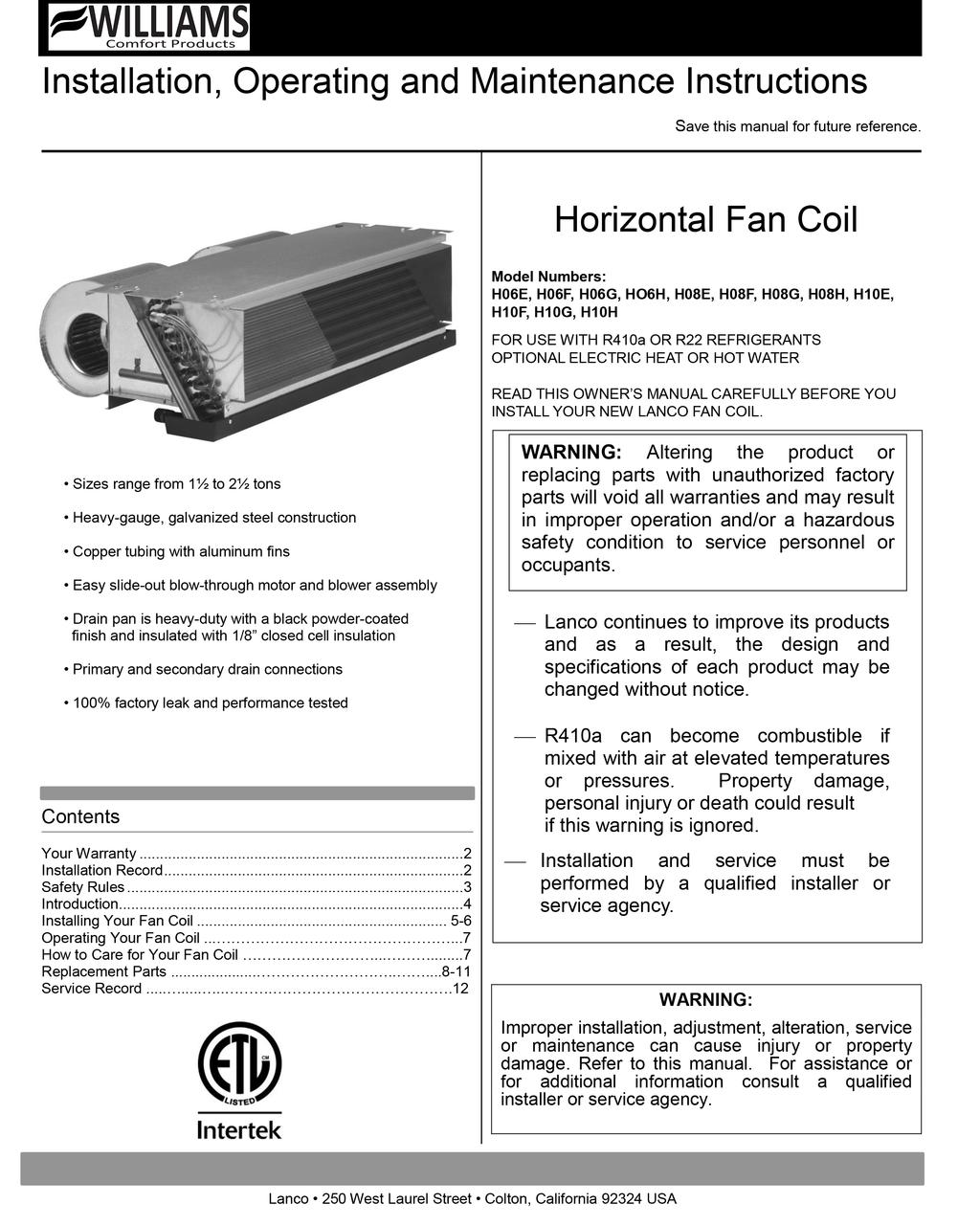
1
2 Your Warranty The manufacturer, Lanco, warrants this fan coil to the original purchaser under the following conditions: LIMITED ONE-YEAR WARRANTY 1. Any part thereof which proves to be defective in material or workmanship within one year from date of original purchase for use will be replaced at the Manufacturer s option, FOB to its factory. 2. No liability is assumed by the Manufacturer for removal or installation labor costs, nor for freight or delivery charges. LIMITATIONS 1. THIS LIMITED WARRANTY IS THE ONLY WARRANTY MADE BY THE MANUFACTURER, IMPLIED WARRANTIES OF MERCHANTABILITY OR FITNESS FOR ANY PARTICULAR PURPOSE ARE LIMITED TO THE SAME ONE YEAR TERM AS THE EXPRESS WARRANTY. UNDER NO CIRCUMSTANCES SHALL THE MANUFACTURER BE LIABLE FOR INCIDENTAL, CONSEQUENTIAL, SPECIAL OR CONTINGENT DAMAGES OR EXPENSES ARISING DIRECTLY OR INDIRECTLY FROM ANY DEFECT IN THE PRODUCT OR ANY COMPONENT OR FROM THE USE THEREOF. THE REMEDIES SET FORTH HEREIN ARE THE EXCLUSIVE REMEDIES AVAILABLE TO THE USER AND ARE IN LIEU OF ALL OTHER REMEDIES. Some states do not allow limitation on how long an implied warranty lasts, and some states do not allow the exclusion or limitation of incidental or consequential damages, so the above limitations or exclusions may not apply to you. 2. This warranty does not include any charge for labor or installation. 3. This warranty does not extend to painted surfaces or to damage or defects resulting from accident, alteration, misuses or abuse or improper installation. 4. This warranty does not cover claims which do not involve defective workmanship or materials. DUTIES OF THE END USER 1. The equipment must be installed by a qualified installer and operated in accordance with the installation instructions furnished with the equipment. 2. Any travel, diagnostic costs, service labor, and labor to repair the defective unit will be the responsibility of the owner. 3. A bill of sale, cancelled check, payment record or permit should be kept to verify purchase date to establish the warranty period. 4. Have the installer enter the requested information in the space below. GENERAL 1. The manufacturer neither assumes nor authorizes any person to assume for it any other obligation or liability in connection with said equipment. 2. Service under this warranty should be obtained by contacting your dealer. Provide the dealer with the model number, serial number, and purchase date verification. 3. If, within a reasonable time after contacting your dealer, satisfactory service has not been received, contact: Customer Service Department, 250 West Laurel Street, Colton, CA for assistance. 4. THIS WARRANTY GIVES YOU SPECIFIC LEGAL RIGHTS AND YOU MAY ALSO HAVE OTHER RIGHTS WHICH VARY FROM STATE TO STATE. Installation Record Model No. Serial No. Original Purchaser Address City and State Zip Dealer Address City and State Zip Installation Date Name Signature (Dealer or authorized representative who certifies that this appliance is installed in accordance with Manufacturer s instructions and local codes.) 2
3 Stay Safe WARNING: Read these rules and the instructions carefully. Failure to follow these rules and instructions could cause a malfunction of the fan coil. This could result in death, serious bodily injury and/or property damage. INSTALLATION MUST CONFORM TO LOCAL CODES. COMPLIANCE WITH ALL CODES IS THE RESPONSIBILITY OF THE INSTALLER. 8. Any access panels, guards or parts removed for servicing must be replaced prior to operating to avoid property damage, bodily injury or death. 9. Always use good safety practices regarding the handling, installation and servicing mechanical equipment. 10. Under no circumstances is the fan coil to be operated without an air filter. 1. The important safety instructions, warnings and cautions in these pages are not meant to cover all possible problems or conditions. Use common sense and caution when installing, maintaining or operating the equipment. Always contact Lanco about any problems or conditions that you do not understand. 2. Use only manufacturer s replacement parts. Use of any other parts in not recommended. 3. It is the sole responsibility of the customer to provide the necessary protection to prevent vandalism and weather protection of the equipment. Under no circumstance should the fan coil be left exposed to the elements. Protect the units from dirt, plaster and other debris during the entire construction phase. Prior to start-up, the entire interior of the unit should be inspected for debris and dirt. Clean, if necessary. Any failure of the unit or damage to the building as a result of improperly protecting and cleaning the unit is not covered by the warranty. 11. When the fan coil is operating, some components operate at high speeds. Personal injury can result in touching these items. 12. Take caution that no internal damage will result if screws or holes are drilled into the cabinet. 13. Always use proper eye protection, safety equipment and tools equipment during the installation. 14. No wiring or other work should be performed without verifying that the fan coil is completely disconnected from the power source and locked out. 4. Units weigh pounds. A minimum of two people are recommended for handling and installation. 5. The equipment must be properly supported. Supports must always be adequate to hold the equipment securely. 6. All power must be disconnected before any installation or service is performed. More than one power source may be supplied to the fan coil. 7. Protect adjacent flammable material when welding or soldering. Use a heat shield to protect against sparks and solder. 3
4 Introduction 4 Introduction The following steps are all needed for proper installation and safe operation of your fan coil. If you have any doubts as to any requirements, check with local authorities. Obtain professional help where needed. All of the checks and adjustments in the Start-Up Procedures are vital to the proper and safe operation of the fan coil. Please read the instructions before you install and use your fan coil, this will help you obtain its full value. It could also help you avoid needless service costs if the answer to the problem is found within this instruction manual. Always consult your local HVAC inspector or building department regarding regulations codes or ordinances which apply to the installation. Check the fan coil nameplate prior to installation. It is the responsibility of the installing contractor to inspect and verify that the unit received is the correct model number, voltage, etc. Any discrepancies should be resolved before uncrating and installation. Lanco is not responsible for any back charges due to an incorrect unit being installed. Upon delivery, examine each unit and all parts carefully for shipping damage. Immediately report any freight damage to the freight carrier and file a freight claim with the carrier. All units are shipped FOB factory; therefore Lanco is not responsible for damage during transit. Returns require written authorization from Lanco. Unauthorized returns will be refused. All material returned will be inspected. Any damage, missing parts, rework or repackaging resulting from prior installation, abuses or neglect will constitute just cause for Lanco to issue partial or no credit. Helpful Installation Information The following material will help you with the installation: NFPA Standard 90. 4
5 Installing Your Fan Coil The following steps are needed for proper installation and safe operation of your fan coil. Installation must adhere to all local and national code requirements. If you have any doubts as to any requirements, obtain professional help. Remember to ALWAYS consult your local HVAC inspector or building department regarding regulations, codes, or ordinances which apply to the installation. This unit must be installed in a manner which will allow the blower panel to be removed in order to clean the coil surface, blower and motor and to provide access to electrical and plumbing controls. When installed in a concealed building space, the installation must conform to the requirements of NFPA Standard 90B. It must be installed level and condensate drain lines must have proper trap height. Water, drain connections, and slope must be made to the unit in accordance with local codes. A free return installation (non-ducted return-air) requires the furred down area be completely sealed (except return-air grille) to ensure that all return air is pulled from the conditioned space and not from other areas of the building as per local code. It is the sole responsibility of the customer to provide the necessary protection to prevent vandalism and weather protection of the equipment. Under no circumstance should the fan coil be left exposed to the elements. Protect the unit from dirt, plaster and other debris during the entire installation phase. Prior to start-up, the entire interior of the unit should be inspected for debris and dirt. Any failure of the unit or damage to the building as a result of improperly protecting and cleaning the unit is not covered by the warranty. Mounting Units weigh pounds. A minimum of two people are recommended for handling and installation. The unit must be securely mounted and the structure sufficient to support the weight of the equipment. All anchors for mounting must be placed and sized to ensure a safe installation. Lanco fan coils are provided with four mounting slots. Mounting hardware is not included. Be sure the fan coil is properly leveled to ensure that the condensate will drain from the fan coil. Ducting All ducting must be installed in accordance with NFPA Standards 90A and 90B. Ducts must be adequately insulated to prevent condensation during the cooling cycle and to minimize any heat loss. Often it is acceptable to use ducting of the same size as the fan coil connections. However, unusual applications or long duct runs must be properly sized by a local professional. Electrical No wiring or other work should be performed without verifying that the fan coil is completely disconnected from the power source and locked out. Verify a good ground connection exists prior to energizing the power source. All wiring must comply with local and national code requirements. Lanco fan coils are provided with a wiring diagram and nameplate data to provide the necessary information needed for field wiring. Wire used for connection to the fan coil must be rated for at least 90 C and comply with local codes. All wiring connections must be tight. Any optional items, such as thermostats and fan switches to be field installed must be wired in accordance with wiring diagram supplied with the unit. Normal Piping Practice This data is intended to explain piping arrangements for direct expansion refrigerant and hot-water coils to the correct inlet and outlet locations. COOLING COILS (Approved for use with R22 or R410A gases) The cooling coils of this unit are for use with a direct expansion refrigerant which operates under high pressure. To be installed only by those licensed to handle these gases. A metering device for the refrigerant has been installed at the factory. This permits the unit to be paired with a variety of condensers. The suction and liquid refrigerant lines must be sized per the condenser manufacturer s specifications. A TXV may also be used and if desired can be ordered from the factory. DO NOT OPERATE IN REVERSE. 5
6 Installing Your Fan Coil Chilled and condensate drain lines must be insulated for efficient operation and to prevent condensate formation. Control valves, shutoff valves and non-insulated water piping must be installed over the drain pan or utilize an accessory drain pan extension. Condensate lines, one primary and one secondary, must be properly pitched to the building drain. Lanco will not assume any liability for damage caused as a result of the condensate drain line not being properly pitched or trapped. Drain line(s) should be made visible for inspection of any problems. The use of a secondary drain pan under the entire unit, with a separate drain line, is advised in areas where water damage is very critical and may be required by local building codes. HOT WATER COILS Hot water coils have one inlet and outlet and may have one- to four-rows. The inlet is always at the bottom of the coil and the outlet is always at the top of the coil. All coils are piped so that the inlet is always on the row farthest downstream from the incoming air. All coils have one or more circuits. Due to the various circuit options available, the inlet, and outlet may change position making the inlet and outlet locations vary. The bottom coil connection, on the leaving-air-side, is the water-supply inlet. All piping must be supported independently from the coil to prevent damage to the soldered joints. All joints must be properly sealed against air leaks to the piping. CAUTION If equipped with hydronic heat, this unit has a hot water coil freeze protector installed; it may not adequately protect the water lines if the unit is installed in areas subjected to freezing temperatures (attics, unoccupied dwellings, etc.). TWO-PIPE COIL DIAGRAMS (Two-Pipe Coils Right-Hand Shown, Left-Hand Opposite) CAUTION If the unit is installed during the winter months, care must be taken so that the unit is not subject to freezing temperatures while filled with water during construction. Coils damaged due to freezing are not covered by the warranty. Lanco fan coil units are suitable for zero clearance to combustible material. All air must be bled out of the system. Any air trapped in the hot-water coil can be released from the system by using the manual air vent on the coil. In hot and humid areas: Do not operate during construction or renovation with windows and doors open causing outside air to enter the building. WARNING RISK OF ELECTRICAL SHOCK! CAN CAUSE INJURY OR DEATH. Disconnect all remote electric power supplies before servicing. Placing the thermostat in the OFF position should not be used for disconnect purposes. 6
7 Care 7 Operating for Your Fan Coil Start-Up Procedure Wiring: The motor must be properly wired and grounded prior to start-up. The wiring diagrams are provided with each unit. The warranty on all motors is void if the motor is burned-out due to incorrect wiring. Wire used for connections to the fan coil must be rated for at least 90 centigrade. All wiring connections must be tight. Check the rating of the unit to determine: voltage, frequency, phase, amperage, appropriate switching, maximum over current protection (MOP), and minimum circuit ampacity (MCA) and full load amps (FLA). All wiring must be done in accordance with applicable local electrical codes and/or standards. Verify a proper ground. Blower Wheel: With the power off, be sure that the blower wheel(s) rotate freely and quietly. To avoid imbalance or vibration, make sure the blower has been cleaned from any installation debris. Housekeeping: To ensure the best performance, be sure the equipment is clean of any debris collected during installation. Access Panels/Filters: All access panels and filters must be in place before operation. Coils: After the fan coil and hydronic piping have been installed and properly insulated as required, pressure test for 24 hours with a minimum of 2½ times the working pressure to insure that there are no leaks in the system. This test should be performed prior to hanging or installation of ceilings, floor coverings, drapes, etc. Any damage caused due to leaks is not covered under the warranty. Drain: The condensate drain must be a minimum of ⅞ OD copper tubing, ¾ galvanized-iron pipe or PVC-type plastic pipe. Be sure the drain pitches downward at a slope of 1-inch to every 10-feet. Install a 3- to 4-inch trap in the condensate line as close to the unit as possible. Make sure the top of the trap is level beneath connection to the unit to prevent condensate from overflowing the drain pan. There are two condensate drain line connections provided. Ensure that any unused connections are plugged. Caring for Your Fan Coil How to Care for Your Fan Coil To attain maximum performance a formal schedule of regular maintenance should be performed. Float Switch (Optional): The optional drain pan float switch position is not adjustable. The float switch must be mounted flush with the edge of the drain pan for optimum performance. Any attempt in moving the float switch in any other position can result in unit failure. Coil: Clean the coil by removing the blower panel and brushing the fins with a stiff, plastic bristle brush, taking care not to bend or damage the fin surface. After brushing, the coil should be vacuumed to remove loose dirt. A fin comb with the proper FPI (fins per inch) spacing may be used to straighten collapsed fins. Cleaning with low pressure compressed air is also acceptable. Note that if suitable air filters are used and properly maintained, the coil should not need cleaning. Motor and Blower: The blower and motor should be cleaned annually. Filters: Change throwaway filters a minimum of every 90 days. Periodic checks should be made during the cooling season to ensure that excessive dust or lint is not accumulating to the extent of interrupting free air flow. If excessive dirt accumulates, the filter should be changed more frequently. Reusable/cleanable air filters should be thoroughly cleaned a minimum of twice a year and have the same periodic checks as throwaway filters. Drain: The drain pan must be inspected before summer operation. All debris in the drain pan should be removed so the condensate will flow out easily. Periodic inspection of the drain pan and condensate piping should be performed during the summer operation to prevent any possibility of it becoming clogged. Lanco will assume no liability for damage caused as a result of the condensate line becoming plugged. CAUTION This unit must be installed in a manner that allows it to operate according to the nameplate data and comply with all applicable codes. Lanco will assume no liability for damage to the unit or building due to misapplication, including field installed control devices not furnished or specified by Lanco. 7
8 Accessories 8 Replacement Parts Model Number Model Number Total Heater kw Strip Heater Part Number Strip Heater kw Quantity Required Hydronic Heat Input Voltage H08E302R10 H08G302R10 1 P V H08E302R20 H08G302R20 2 P V H08E302R30 H08G302R30 3 P V H08E302R40 H08G302R40 4 P V H08E302R50 H08G302R50 5 P V H08E302R60 H08G302R60 6 P V H08E302R70 H08G302R70 7 M V H08E302R80 H08G302R80 8 P V H08E302R90 H08G302R90 9 P V H08F321R00 H08H321R00 X 120V H08F322R00 H08H322R00 X 240V H08E301R00 H08G301R00 120V H08E302R00 H08G302R00 204V Note: All Electric Heat is 240V 8

9 Replacement Parts Basic No Heat How to Order Replacement Parts When ordering replacement parts, always provide the following information: 1. MODEL NUMBER 2. SERIAL NUMBER 3. PART NUMBER 4. PART DESCRIPTION All parts listed herein may be ordered from your equipment supplier. The model number of your LANCO fan coil will be found on the nameplate. (*) Not Shown Item Part Number Description Quantity Required 1 M Coil Side - Right 1 2 M Coil Side - Left 1 3 M Coil Top Panel 1 4 M Blower Panel 1 5 M Blower Assembly 2 6 M Motor Mount Support Bracket 1 7 M Spark Tray 1 8 P Coil DX 1 9 M Drain Pan 1 10 P Motor 1/5 HP 120/1/ P Motor 1/5 HP /1/ M Junction Box Assembly 1 12 M Coil Bottom Panel Cover 1 13 M Coil Bottom Panel Channel 1 14 P *TXV 410a / R22 (Optional) 1 15 P *Filter (33 by 9 by 1 ) 1 16 P *Chatleff Flange Nut Assy 1 17 P *Orifice Piston.051 ID 1 18 P *Orifice Piston.059 ID 1 9
10 Replacement Parts Basic with Electric Heat Item Part Number Description 10 Quantity Required 1 M Coil Side - Right 1 2 M Coil Side - Left 1 3 M Coil Top Panel 1 4 M Blower Panel 1 5 M Blower Assembly 2 6 M Motor Mount Support Bracket 1 7 M Spark Tray 1 8 P Coil DX 1 9 M Drain Pan 1 10 P Motor 1/5 HP /1/ (*) Refer to chart on page 8 12 M Strip Heater Support Bracket 2 13 M Strip Heater Support Bracket 2 14 M Coil Bottom Panel Channel 1 15 M Coil Bottom Panel Cover 1 16 M Junction Box Assembly 1 17 P *TXV 410a / R22 (Optional) 1 18 P * Filter (33 by 9 by 1") 1 19 P *Chatleff Flange Nut Assy 1 20 P *Orifice Piston.051 ID 1 21 P *Orifice Piston.059 ID 1


11 Replacement Parts Basic with Hot Water How to Order Replacement Parts When ordering replacement parts, always provide the following information: 1. MODEL NUMBER 2. SERIAL NUMBER 3. PART NUMBER 4. PART DESCRIPTION All parts listed herein may be ordered from your equipment supplier. The model number of your LANCO fan coil will be found on the nameplate. (*) Not shown Item Part Number Description Quantity Required 1 M Coil Top Panel 1 2 M Blower Panel 1 3 M Blower Assembly 2 4 M Support Bracket Motor Mount 1 5 M Spark Tray 1 6 P Coil DX 1 7 M Coil Hot Water 1 8 M Drain Pan 1 9 M Coil Bottom Panel Channel 1 10 P Motor 1/5 HP 120/1/ P Motor 1/5 HP /1/ M Junction Box Assembly 1 12 M Coil Bottom Panel Cover 1 13 M Freeze Stat Bracket 1 14 P Freeze Stat 1 15 P *TXV 410a (Optional) 1 16 P *Filter (33 by 9 by 1 ) 1 17 P *Chatleff Flange Nut Assy 1 18 P *Orifice Piston.051 ID 1 19 P *Orifice Piston.059 ID 1 11
12 Replacement Service Record Parts Address Model No. Serial No. Model Description Installation Date Filter Part No. Voltage Amps Date Service Performed Parts Required Service Company Signature 250 West Laurel Street, Colton, CA (909) FAX: (909) e-wfc-fc.com 12 D Revised All Rights Reserved
Installation, Operating & Maintenance Instructions. Air Handler Models: AH & AV
 Installation, Operating & Maintenance Instructions Air Handler Models: AH & AV Table of Contents Table of Contents... 2 Product Safety... 2 Important Information About Safety Instructions... 2 Receiving...
Installation, Operating & Maintenance Instructions. Horizontal Models: LH & HL
 Installation, Operating & Maintenance Instructions Horizontal Models: LH & HL Table of Contents Table of Contents... 2 Product Safety... 2 Important Information About Safety Instructions... 2 Receiving...
MAN AUTO IMPORTANT INSTRUCTIONS PLEASE READ THIS MANUAL BEFORE INSTALLING AND USING APPLIANCE
 Wall Heater Fan MODEL #: 2275 This fan is a CSA approved component compatible with these Williams wall heaters only: 1076512.9 2076512.9 3076512.9 1276512 1876512 3076512 1076511.9 2076511.9 IMPORTANT
Installation, Operating & Maintenance Instructions. High Performance Horizontal Models: HH & CH
 Installation, Operating & Maintenance Instructions High Performance Horizontal Models: HH & CH Table of Contents Table of Contents... 2 Product Safety... 2 Important Information About Safety Instructions...
WMWLB / WMWFM / WTWLB / WTWFM Series Hydronic Heating Unit
 January 2008 WMWLB / WMWFM / WTWLB / WTWFM Series Hydronic Heating Unit Installation Operation Maintenance The units are designed for permanent up flow, counter flow, or horizontal left or right airflow
CROWN. Boiler Co. Santa-Fe Series. Hydronic Air Handlers INSTALLATION, OPERATION & MAINTENANCE INSTRUCTIONS
 CROWN Boiler Co Santa-Fe Series Hydronic Air Handlers INSTALLATION, OPERATION & MAINTENANCE INSTRUCTIONS These instructions must be affixed on or adjacent to the air handler Models: SAC049A20 SAC059A25
WKS 4000 SERIES (USA only) --INSTALLATION INSTRUCTIONS--
 --INSTALLATION INSTRUCTIONS--") 8610 Production Avenue San Diego, California 92121 (858) 566-7465 Fax (858) 566-1943 WKS 4000 SERIES (USA only) --INSTALLATION INSTRUCTIONS-- Thank you for choosing a BREEZAIRE cooling unit. We believe
8610 Production Avenue San Diego, California 92121 (858) 566-7465 Fax (858) 566-1943 WKS 4000 SERIES (USA only) --INSTALLATION INSTRUCTIONS-- Thank you for choosing a BREEZAIRE cooling unit. We believe
RPI Industries, Inc.
 IMPORTANT: THE FOLLOWING INFORMATION SHOULD BE RETAINED FOR FUTURE REFERENCE RPI Industries, Inc. building a better case for sales BAKERY and DELI USE AND SERVICE MANUAL WARRANTY INFORMATION SPECIFICATIONS
R Series B & T2 Model
 FRONT R Series B & T2 Model Fan Forced Wall Heaters 4-1/4 (108mm) NOTE: Knockouts in top same dimensions 3-1/4 3-1/4 (108mm) (108mm) as bottom 16-7/8 (429mm) 13-7/8 (352mm) BOTTOM 13-7/8 (352mm) 7-3/4
Horizontal Bottle Cooler Installation and Operation Manual
 Speeds Up the Pace of Innovation Horizontal Bottle Cooler Installation and Operation Manual Please read this manual completely before attempting to install or operate this equipment! TBC-50SD, 50SB/ TBC-95SD,
G Series SAVE THESE INSTRUCTIONS. (Model B) Convector Heater for Hazardous Locations GENERAL! INSTALLATION
 Convector Heater for Hazardous Locations GENERAL! INSTALLATION") G Series (Model B) Convector Heater for Hazardous Locations Type G-Series Convection Heaters are designed for use in Class I, Div. I hazardous environments. Units without control options are suitable for
G Series (Model B) Convector Heater for Hazardous Locations Type G-Series Convection Heaters are designed for use in Class I, Div. I hazardous environments. Units without control options are suitable for
Installation & Maintenance Instructions
 IMPORTANT INSTRUCTIONS READ AND SAVE THESE INSTRUCTIONS Saving energy and creating healthy, comfortable environments No. II-450 Date July, 2015 DRIVE-THRU UNIT 3 AIR CURTAIN SERIES DTU03 for outdoor use
Standard and CELDEK Evaporative Cooler Modules Installation, Operation, and Maintenance Manual
 Standard and CELDEK Evaporative Cooler Modules Installation, Operation, and Maintenance Manual Standard Evaporative Cooler CELDEK Evaporative Cooler RECEIVING AND INSPECTION Upon receiving unit, check
RPI Industries, Inc.
 IMPORTANT: THE FOLLOWING INFORMATION SHOULD BE RETAINED FOR FUTURE REFERENCE RPI Industries, Inc. building a better case for sales CONFECTIONERY USE & SERVICE MANUAL WARRANTY INFORMATION For Models Bradford
OPERATION MANUAL Dated: 04/09/2018 Document Name: SHV _OM Page 1 of 8. Ion Technologies SHV40, 75 & 100 Sewage Ejector Pump SAFETY WARNINGS
 Ion Technologies SHV40, 75 & 100 Sewage Ejector Pump Page 1 of 8 biohazard risk exists. Installer(s) and/or service personnel must use proper Personal Protective Equipment and follow handling procedures
Standard and CELDEK Evaporative Cooler Modules Installation, Operation, and Maintenance Manual
 Standard and CELDEK Evaporative Cooler Modules Installation, Operation, and Maintenance Manual Standard Evaporative Cooler CELDEK Evaporative Cooler RECEIVING AND INSPECTION Upon receiving unit, check
InstructIon Manual KrEs EQuIPMEnt stands
 Instruction Manual Instruction Manual SELF-CONTAINED AND REMOTE Kairak KRES model refrigerated equipment stand units are available in many lengths from 36 to 120 inches long. These units are available
REFRIGERATED DROP-INS (2-6)FT-DI Installation and Operating Manual
FT-DI Installation and Operating Manual") REFRIGERATED DROP-INS (2-6)FT-DI Installation and Operating Manual For service information call 800-544-3057 Please have the following information available before calling. Information can be found on
REFRIGERATED DROP-INS (2-6)FT-DI Installation and Operating Manual For service information call 800-544-3057 Please have the following information available before calling. Information can be found on
ALL WEATHER SL-SERIES QUARTZ TUBE ELECTRIC INFRARED RADIANT HEATER INSTALLATION USE & CARE MANUAL
 ALL WEATHER SL-SERIES QUARTZ TUBE ELECTRIC INFRARED RADIANT HEATER TABLE OF CONTENTS: INSTALLATION USE & CARE MANUAL IMPORTANT INFORMATION Assembly Instructions 2 Wiring Instructions 2 Outdoor Installation
MANUAL 8/12/05. Model BKP TM 100 INSTALLATION, OPERATION & MAINTENANCE. Commercial High Efficiency Heat Pipe Dehumidifier
 MANUAL 8/12/05 INSTALLATION, OPERATION & MAINTENANCE Commercial High Efficiency Heat Pipe Dehumidifier Model BKP TM 100 Heat Pipe Technology, Inc. 6904 Parke East Blvd. Tampa FL 33610 Tel: (813) 470-4250
CELDEK Evaporative Cooler Module Installation, Operation, and Maintenance Manual. CELDEK Evaporative Cooler
 CELDEK Evaporative Cooler Module Installation, Operation, and Maintenance Manual CELDEK Evaporative Cooler RECEIVING AND INSPECTION Upon receiving unit, check for any interior and exterior damage, and
DBF 4XL Dryer Booster Fans
 Installation and Operation Manual Item #: 401315 Rev Date: 050814 DBF 4XL Dryer Booster Fans DBF4XL Kit Includes: Dryer Booster Fan, 1 pc Fan Mounting Bracket and Hardware, 1 pc Wall Label (Mount on wasll
INSTALLATION, OPERATION AND MAINTENANCE INSTRUCTIONS
 INSTALLATION, OPERATION AND MAINTENANCE INSTRUCTIONS AquaArctic Remote Water Chiller A9100080 -A TECHNICAL ASSISTANCE TOLL FREE TELEPHONE NUMBER: 1.800.591.9360 Technical Assistance Fax: 1.626.855.4894
Professional Warming Drawer and Warming Drawer Cabinet
 Professional Warming Drawer and Warming Drawer Cabinet Care & Use/Installation Instructions Models: (C)VQEWD5300SS (C)VQEWD5420SS IMPORTANT SAFETY INSTRUCTIONS WARNING: Read this manual carefully and completely
FLCH4R Garage and Utility Electric Heater
 FLCH4R Garage and Utility Electric Heater Installation, Operation & Maintenance Instructions Model No. Volts Amps Watts BTU/HR Phase High Low High Low High Low Min Fuse Size* FLCH4R 208 17.3 8.66 3600
Please Read and Save These Instructions.
 Page 1 of 8 RadonAway Ward Hill, MA. GP500 Fan Installation Instructions Please Read and Save These Instructions. DO NOT CONNECT POWER SUPPLY UNTIL FAN IS COMPLETELY INSTALLED. MAKE SURE ELECTRICAL SERVICE
Installation & Operation Manual Ice Cream Freezers
 Installation & Operation Manual Ice Cream Freezers Please read this manual completely before installing or operating this unit! BACF11 BACF15 Blue Air reserves the right to make product modification at
Blue Air. Commercial Refrigeration Inc. Installation & Operation Manual Ice Cream Freezers
 Blue Air Commercial Refrigeration Inc. Installation & Operation Manual Ice Cream Freezers Please read this manual completely before installing or operating this unit! BACF11 BACF15 BACRF14 Blue Air reserves
IMPORTANT SAFETY INFORMATION
 OPERATION INSTALLATION PARTS MANUAL www.fostoriaindustries.com Made in U.S.A. ELECTRIC PORTABLE HEATER FES-1024-1CA 08860010 YES-1024-1CA 08861510 FES-1520-3A 08860110 YES-1520-3A 08860810 FES-1524-1A
Model R060 Installation - Operation Manual
 Residential Heat Pump Water Heaters Model R060 Installation - Operation Manual Important Note Read this entire manual before beginning installation Manufactured By: 6670-A Corners Industrial Court Norcross,
Installation, Operating & Maintenance Instructions. Vertical Stack Models: ER & DR
 Installation, Operating & Maintenance Instructions Vertical Stack Models: ER & DR Table of Contents Table of Contents... 2 Product Safety... 2 Important Information About Safety Instructions... 2 Receiving...
FES - Series Portable Electric Heaters. YES - Series Suspended Electric Heaters CONTENTS
 FOSTORIA INDUSTRIES, INC. A DIVISION OF FES - Series Portable Electric Heaters YES - Series Suspended Electric Heaters (FES-1524-3E shown) IMPORTANT SAFETY INFORMATION INSIDE Serious injury or death possible.
IAQ Series. Bosch IAQ Photo Catalytic Oxidizer (PCO) Residential Application. Installation Manual and Owner s Guide
 Residential Application. Installation Manual and Owner s Guide") Installation Manual and Owner s Guide IAQ Series Bosch IAQ Photo Catalytic Oxidizer (PCO) Residential Application PCOB-09012-0--A - 9" PCO BULB PCOB-14024-0--A - 14" PCO BULB 67202220344 Revised 07-12
Installation Manual and Owner s Guide IAQ Series Bosch IAQ Photo Catalytic Oxidizer (PCO) Residential Application PCOB-09012-0--A - 9" PCO BULB PCOB-14024-0--A - 14" PCO BULB 67202220344 Revised 07-12
Operating Instructions & Parts Manual. Silent Low-Profile Ceiling Fans. Models 3DPE2A, 3DPE3A, 1UBH6B, 1UBH7B, 1UBH8A, 5AE68B, 5AE69A
 Operating Instructions & Parts Manual EN Silent Low-Profile Ceiling Fans Models 3DPE2A, 3DPE3A, 1UBH6B, 1UBH7B, 1UBH8A, 5AE68B, 5AE69A 465933 PLEASE READ AND SAVE THESE INSTRUCTIONS. READ CAREFULLY BEFORE
SPA BLOWER OWNER'S MANUAL XXXX, XXXX, XXXX, XXXX, XXXX, XXXX fax
 SPA BLOWER OWNER'S MANUAL 80015-XXXX, 80016-XXXX, 80017-XXXX, 80018-XXXX, 80019-XXXX, 80020-XXXX fax 888.610.3839 2015 323300-015 6/15 THIS PAGE INTENTIONALLY LEFT BLANK. 2 Operating Instructions and Parts
ADVANTAGE SERIES KXRP28 AIR-TO-AIR HEAT EXCHANGER
 Keep This Manual With Heat Exchanger Find additional information on this model at kooltronic.com or use the Technical Documents QR code below. Technical Documents ADVANTAGE SERIES KXRP28 AIR-TO-AIR HEAT
Service Parts, Kits and Accessories
 The parts identification guides on the following pages have been designed to give a quick reference to component parts used on pilot ignition agricultural building heaters. The guides identify components
Warnings 2. Installation Instructions 3. Wiring Instructions 3. Mounting Instructions 4. Replacement Element Installation 5. Replacement Parts 5
 TABLE OF CONTENTS Warnings 2 Installation Instructions 3 Wiring Instructions 3 Mounting Instructions 4 Replacement Element Installation 5 Replacement Parts 5 Heater Coverage Areas 6 General Notes 6 Maintenance
A910.8A Remote Water Chiller, 8 GPH A A / A A-220V TECHNICAL ASSISTANCE TOLL FREE TELEPHONE NUMBER:
 Remote Water Chiller, 8 GPH A9100080-A / A9100080-A-220V TECHNICAL ASSISTANCE TOLL FREE TELEPHONE NUMBER: 1.800.591.9360 Technical Assistance Fax: 1.626.855.4894 NOTES TO INSTALLER: 1. Please leave this
SF180 Installation Instructions
 SF180 Installation Instructions 1 Fan Installation & Operating Instructions Please Read and Save These Instructions. DO NOT CONNECT POWER SUPPLY UNTIL FAN IS COMPLETELY INSTALLED. MAKE SURE ELECTRICAL
Warnings 2. Installation Instructions 3. Wiring Instructions 3. Mounting Instructions 4-5. Replacement Element Installation 5. Replacement Parts 5-6
 TABLE OF CONTENTS Warnings 2 Installation Instructions 3 Wiring Instructions 3 Mounting Instructions 4-5 Replacement Element Installation 5 Replacement Parts 5-6 Heater Coverage Areas 6 General Notes 6
Three Phase Simplex. Installation (937) Installation Instructions and Operation/Troubleshooting Manual. Installation of Floats.
 Installation Instructions and Operation/Troubleshooting Manual. Installation of Floats.") Three Phase Simplex Installation Instructions and Operation/Troubleshooting Manual This control panel must be installed and serviced by a licensed electrician in accordance with the National Electric Code
Three Phase Simplex Installation Instructions and Operation/Troubleshooting Manual This control panel must be installed and serviced by a licensed electrician in accordance with the National Electric Code
THE BARCLAY HUGGER CEILING FAN INSTALLATION INSTRUCTIONS
 THE BARCLAY HUGGER CEILING FAN INSTALLATION INSTRUCTIONS Please read and save these instructions These instructions are to be used in the installation of the following QUORUM INTERNATIONAL fans... The
INSTALLATION USE & CARE MANUAL ALL WEATHER SL-SERIES QUARTZ TUBE ELECTRIC INFRARED RADIANT HEATER
 INSTALLATION USE & CARE MANUAL ALL WEATHER SL-SERIES QUARTZ TUBE ELECTRIC INFRARED RADIANT HEATER TABLE OF CONTENTS IMPORTANT INFORMATION Warnings 2 Installation Instructions 3 Wiring Instructions 3 Outdoor
VSA/VSB & KSA/KSB Series Air Doors
 READ AND SAVE THESE INSTRUCTIONS No.: II-230 Date: October, 2007 VSA/VSB & KSA/KSB Series Air Doors Installation & Maintenance Instructions WARNING: TO REDUCE THE RISK OF FIRE, ELECTRIC SHOCK, OR INJURY
IN020 Rev F Page 1 of 8
 IN020 Rev F Page 1 of 8 RadonAway Ward Hill, MA. Series Fan Installation Instructions Please Read and Save These Instructions. DO NOT CONNECT POWER SUPPLY UNTIL FAN IS COMPLETELY INSTALLED. MAKE SURE ELECTRICAL
Vertical Concealed Fan Coil. FCVC Series MANUAL INSTALLATION, OPERATION, & MAINTENANCE
 MANUAL INSTALLATION, OPERATION, & MAINTENANCE Vertical Concealed Fan Coil FCVC Series v100 Issue Date: 12/21/15 2015 Price Industries Limited. All rights reserved. TABLE OF CONTENTS Product Overview Safety
KPHE24 SERIES WATER-TO-AIR HEAT EXCHANGER
 Keep This Manual With Heat Exchanger Find additional information on this model at kooltronic.com or use the Technical Documents QR code below. Technical Documents KPHE24 SERIES WATER-TO-AIR HEAT EXCHANGER
AIR CONDITIONER ELECTRONIC CONTROL
 READ AND SAVE THESE INSTRUCTIONS AIR CONDITIONER ELECTRONIC CONTROL ROOM AIR CONDITIONER WARRANTY Your product is protected by this warranty Your appliance is warranted by Electrolux. Electrolux has authorized
CH250 AND CH251 CHILLERS
 CH250 AND CH251 CHILLERS Operator s & Installation Manual Release Date: April 19, 2004 Publication Number: 620914801 Revision Date: May 15, 2015 Revision: G Visit the Cornelius web site at www.cornelius.com
RPI Industries, Inc.
 RPI Industries, Inc. AIR SCREEN and SELF-SERVE OPERATION AND SERVICE MANUAL WARRANTY INFORMATION For Models Stratus SCRFC48R-SSI SCRFC60R-SSI SCRFC72R-SSI SCRFC48R-SSII SCRFC72R-SSII SCRFC48R-SSIII SCRFC72R-SSIII
IMPORTANT INSTRUCTIONS
 IMPORTANT INSTRUCTIONS W Fan Force Electric Space Heater DANGER ELECTRIC SHOCK OR FIRE HAZARD Figure 1 Covers all W Series models WARNING Read Carefully - These instructions are written in an effort to
Turbo Air Speed up the Pace of Innovation TBB-4SB CAUTION! PLEASE KEEP POWER SWITCH ON BEFORE OPERATING THIS EQUIPMENT
 Turbo Air Speed up the Pace of Innovation CAUTION! PLEASE KEEP POWER SWITCH ON BEFORE OPERATING THIS EQUIPMENT Underbar Equipment Back Bars Installation and Operation Manual Please read this manual completely
MaxLite LED Vapor Tight Linear Fixture
 General Safety Information To reduce the risk of death, personal injury or property damage from fire, electric shock, falling parts, cuts/abrasions, and other hazards read all warnings and instructions
Surna 25-Ton Chiller Operating & Maintenance Manual
 www.surna.com 303.993.5271 Surna 25-Ton Chiller Operating & Maintenance Manual Models: 300F3-3. 300F4-3, 300FW-3 Revised: July 2015 Table of Contents Warranty Information 4 Limited Warranty 4 Limitation
Owner s Manual Refrigerated Compressed Air Dryers Models F-200, 250, 300 & F350
 Owner s Manual Refrigerated Compressed Air Dryers Models F-200, 250, 300 & F350 Read carefully before attempting to assemble, install, operate or maintain the product described. Protect yourself and others
INSTALLATION AND OPERATING MANUAL
 INSTALLATION AND OPERATING MANUAL Refrigerated Island Merchandiser FOR PARTS & SERVICE Contact: Piper Products, Inc. Phone: (800) 544-3057 Ask for Service Department IMPORTANT! This manual contains important
INSTALLATION INSTRUCTIONS
 INSTALLATION INSTRUCTIONS Keep these instructions with the boiler at all times. BOYERTOWN FURNACE CO. PO Box 100 BOYERTOWN, PA 19512 1-610-369-1450 www.boyertownfurnace.com 5-25-12 2 Danger Warning Caution
SPX SERIES PACKAGED AIR CONDITIONING/HEAT PUMP UNITS INSTALLATION, OPERATION AND MAINTENANCE INSTRUCTIONS
 SPX SERIES PACKAGED AIR CONDITIONING/HEAT PUMP UNITS INSTALLATION, OPERATION AND MAINTENANCE INSTRUCTIONS **WARNING TO INSTALLER, SERVICE PERSONNEL AND OWNER** Altering the product or replacing parts with
DEDPV-705, DEDPV-705 Hi Alt Dryer Exhaust Duct Power Ventilator (DEDPV)
") Installation and Operation Manual Item #: 483443 Rev Date: 2018-04-23 DEDPV-705, DEDPV-705 Hi Alt Dryer Exhaust Duct Power Ventilator (DEDPV) DEDPV-705 Kit Includes: Inline Fan with Integral Control, 1
Installation and Operation Manual Item #: 483443 Rev Date: 2018-04-23 DEDPV-705, DEDPV-705 Hi Alt Dryer Exhaust Duct Power Ventilator (DEDPV) DEDPV-705 Kit Includes: Inline Fan with Integral Control, 1
INSTALLATION AND OPERATING MANUAL
 INSTALLATION AND OPERATING MANUAL Salad Bars Olive Bars Food Prep Cases Refrigerated Cases with Air-Over Displays Refrigerated Cases with Coppered Cold Well Displays Cases with Under-Counter Refrigerators
OKB, OKD, & OKH Series
 ISO 9001 Infrared Radiant Heaters OKB, OKD, & OKH Series Installation, Operation, Maintenance Instructions & Spare Parts CE Certified HIGH TEMPERATURE, RISK OF FIRE, FIRE/EXPLOSION HAZARD. During operation,
SEISCO SUPERCHARGER EXTENDER/BOOSTER INSTALLATION GUIDE & OWNERS MANUAL
 SEISCO SUPERCHARGER EXTENDER/BOOSTER INSTALLATION GUIDE & OWNERS MANUAL This manual is provided as a guide to installation. All installations must comply with any and all local and national electrical
INSTALLATION, OPERATION AND MAINTENANCE
 INLINE HEATER INSTALLATION, OPERATION AND MAINTENANCE MODELS: ILS SERIES 1.5kW 120V SINGLE PHASE BEFORE YOU BEGIN CHECK ALL ELECTRICAL CONNECTIONS TO ALL COMPONENTS WITHIN THE HEATER FOR TIGHTNESS. CONNECTIONS
CVS Model Inline Multi-Port Ventilators
 Installation Manual Item #: 402332 Rev Date: 081613 CVS Model Inline Multi-Port Ventilators United States 10048 Industrial Blvd., Lenexa, KS, 66215 Tel.: 800.747.1762 Fax: 800.487.9915 Canada 50 Kanalflakt
Installation & Maintenance Instructions
 PRH Series Plenum Heaters Installation & Maintenance Instructions Dear Owner, Congratulations! Thank you for purchasing this new heater manufactured by Marley Engineered Products. You have made a wise
Part No Revised January 30, 2007 SAFETY PRECAUTIONS
 DUAL ZONE STAGING CABINET Instruction Manual Part No. 44406 Revised January 30, 2007 SAFETY PRECAUTIONS SAFETY PRECAUTIONS INTRODUCTION This manual covers the model #2856. The unit is designed to provide
IMpORTANT SAFETy INSTRUcTIONS
 Table of contents SAFETy SETUp OpERATION MAINTENANcE Safety... 2 Specifications... 4 Setup... 4 Operation... 6 WARNING SyMBOLS AND DEFINITIONS Maintenance... 9 Parts List and Diagram... 10 Warranty...
TWIN-FLOIII HEATER INSPECT THE SHIPMENT IMMEDIATELY WHEN RECEIVED TO DETERMINE IF ANY DAMAGE HAS OCCURRED DURING SHIPMENT.
 TFII-11 Beacon/Morris TWIN-FLOIII HEATER INSTALLATION INSTRUCTIONS TYPES K, W, & F ATTENTION: READ THESE INSTRUCTIONS CAREFULLY BEFORE ATTEMPTING TO INSTALL, OPERATE, OR SERVICE THE BEACON MORRIS TWIN-FLO
INSTALLATION AND OPERATING MANUAL
 INSTALLATION AND OPERATING MANUAL Refrigerated Merchandisers with Air-Over Displays Refrigerated Low-Profile Mobile Merchandiser Refrigerated High-Profile Mobile Merchandiser Refrigerated Grab-N-Go Merchandiser
RP, GP, XP Pro Series Installation Instructions
 RP, GP, XP Pro Series Installation Instructions IN095 Rev B 0718 3 Saber Way, Ward Hill, MA 01835 radonaway.com 1 Fan Installation & Operating Instructions RP, GP, XP Series Fans Please Read and Save These
36 & 48 E-Z Cone Fan. Installation & Operator s Instruction Manual (Direct Drive)
") 36 & 48 E-Z Cone Fan Installation & Operator s Instruction Manual (Direct Drive) September 1997 MV1433C Chore-Time Warranty Chore-Time Equipment warrants each new product manufactured by it to be free
36 & 48 E-Z Cone Fan Installation & Operator s Instruction Manual (Direct Drive) September 1997 MV1433C Chore-Time Warranty Chore-Time Equipment warrants each new product manufactured by it to be free
RHGN-H: COMMERCIAL AIR HANDLER WITH VARIABLE FREQUENCY DRIVE (VFD) NOMINAL 10 TONS R-410A REFRIGERANT 2-STAGE AIR-FLOW
 NOMINAL 10 TONS R-410A REFRIGERANT 2-STAGE AIR-FLOW") INSTALLATION INSTRUCTIONS RHGN-H: COMMERCIAL AIR HANDLER WITH VARIABLE FREQUENCY DRIVE (VFD) NOMINAL 10 TONS R-410A REFRIGERANT 2-STAGE AIR-FLOW 92-106595-01-00 TABLE OF CONTENTS Introduction.......................................
INSTALLATION INSTRUCTIONS RHGN-H: COMMERCIAL AIR HANDLER WITH VARIABLE FREQUENCY DRIVE (VFD) NOMINAL 10 TONS R-410A REFRIGERANT 2-STAGE AIR-FLOW 92-106595-01-00 TABLE OF CONTENTS Introduction.......................................
IMPORTANT SAFETY INFORMATION:
 Owner s Manual Model G70 IMPORTANT SAFETY INFORMATION: Always read this manual first before attempting to install or use this heater. For your safety, always comply with all warnings and safety instructions
IMPORTANT SAFETY INFORMATION:
 Owner s Manual Model CUH05B31T IMPORTANT SAFETY INFORMATION: Always read this manual first before attempting to install or use this heater. For your safety, always comply with all warnings and safety instructions
OPERATING INSTRUCTIONS
 OPERATING INSTRUCTIONS SPECIALTY REFRIGERATED TRANSPORT CABINETS FOR SATELLITE LOCATIONS RBQ-96 Caution: Read the instructions before using the machine. CONGRATULATIONS......and thank you for purchasing
FLUID COIL INSTALLATION OPERATION AND MAINTENANCE
 LUID COIL INSTALLATION OPERATION AND MAINTENANCE Commercial Products PO Box 1457 / 1000 Heatcraft Drive, Grenada, MS 38902-1457 Tel: 800-225-4328 / 662-229-4000 ax: 662-229-4212 Email: coils@heatcraft.com
Condensate Pump. Installation and Safety Instructions CP-16 CP
 Condensate Pump Installation and Safety Instructions CP-16 CP-16-230 CP-16 CP-16-230 Rated Voltage 120 Volts / 60 Hz 220 Volts / 60 Hz (208-230) Rated Current Draw 1.9 Amps 1.0 Amps Input Type USA 3-prong
HS Series Installation & Operating Instructions RadonAway
 The World s Leading Radon Fan Manufaturer HS Series Installation & Operating Instructions RadonAway 3 Saber Way Ward Hill, MA 01835 www.radonaway.com P/N IN007-REV J 9/13 RadonAway Ward Hill, MA. HS Series
INSTRUCTION MANUAL HS-229G
 INSTRUCTION MANUAL HS-229G 510977 STEP 1 - Where to Install the Thermostatic Steam Trap Determine where to install the thermostatic steam trap based on the following information. a. The trap should be
Model H1011.8/H1011.8HPS Water Cooler
 455 Kleppe Lane Sparks, NV 8943-6467 (775) 359-472 Fax (775) 359-7424 E-mail: haws@hawsco.com website: www.hawsco.com Model H0.8/H0.8HPS Water Cooler INSTALLATION, OPERATION & MAINTENANCE INSTRUCTIONS
INSTALLATION INSTRUCTIONS TXV Horizontal Duct Coils EHD
 TXV Horizontal Duct s EHD These instructions must be read and understood completely before attempting installation. It is important that the Blower and Duct System be properly sized to allow the system
MODEL HS115-3, HS115-4 & HS115-5 WIRING DIAGRAM ADDENDUM
 TJERNLUND PRODUCTS, INC. 1601 Ninth Street White Bear Lake, MN 55110-6794 PHONE (800) 255-4208 (651) 426-2993 FAX (651) 426-9547 Visit our web site www.tjernlund.com MODEL HS115-3, HS115-4 & HS115-5 WIRING
Please Read And Save These Instructions.
 RadonAway Ward Hill, MA XP/GP/XR Series Fan Installation Instructions Please Read And Save These Instructions. DO NOT CONNECT POWER SUPPLY UNTIL FAN IS COMPLETELY INSTALLED. MAKE SURE ELECTRICAL SERVICE
1 HP Air Mover. Owner s Manual
 1 HP Air Mover Owner s Manual WARNING: Read carefully and understand all ASSEMBLY AND OPERATION INSTRUCTIONS before operating. Failure to follow the safety rules and other basic safety precautions may
Model RGAC/SGAC Self Contained Cooling/Gas Heat MODELS RGAC & SGAC - R22 USER'S INFORMATION, MAINTENANCE AND SERVICE MANUAL
 Model RGAC/SGAC Self Contained Cooling/Gas Heat Supersedes: 145.24-O1 (708) Units Form 145.24-O1 (908) MODELS RGAC & SGAC - R22 USER'S INFORMATION, MAINTENANCE AND SERVICE MANUAL CATEGORY III GAS HEATING/ELECTRIC
Milk Coolers Installation and Operation Manual Please read this manual completely before attempting to install or operate this equipment!
 Turbo Air Speed up the Pace of Innovation CAUTION! PLEASE KEEP POWER SWITCH ON BEFORE OPERATING THIS EQUIPMENT Milk Coolers Installation and Operation Manual Please read this manual completely before attempting
Henny Penny Island Warmer Model HMI-103 Model HMI-105 TECHNICAL MANUAL
 Henny Penny Island Warmer Model HMI-103 Model HMI-105 TECHNICAL MANUAL THIS PAGE INTENTIONALLY LEFT BLANK. Section TABLE OF CONTENTS Page Section 1. TROUBLESHOOTING... 1-1 1-1. Introduction... 1-1 1-2.
INSTALLATION INSTRUCTIONS Cased N Coil, Horizontal ENH4X
 INSTALLATION INSTRUCTIONS Cased N, Horizontal ENH4X NOTE: Read the entire instruction manual before starting the installation. SAFETY CONSIDERATIONS Improper installation, adjustment, alteration, service,
WMHP Series R410a Heat Pump INSTALLATION INSTRUCTIONS
 WMHP Series R410a Heat Pump INSTALLATION INSTRUCTIONS **WARNING TO INSTALLER, SERVICE PERSONNEL AND OWNER** Altering the product or replacing parts with non authorized factory parts voids all warranty
SeasonMaker Hi-Line Fan-coil Unit Model HSS S30 through S80
 Installation & Maintenance Data IM 255-6 SeasonMaker Hi-Line Fan-coil Unit Model HSS S30 through S80 Group: Fan coil Part Number: # 106332400 Date: August 2000 Table of Contents Inspection............................................................................
INSTALLATION USE & CARE MANUAL ALL WEATHER W-SERIES AND WD-SERIES QUARTZ TUBE ELECTRIC INFRARED RADIANT HEATER
 INSTALLATION USE & CARE MANUAL ALL WEATHER W-SERIES AND WD-SERIES QUARTZ TUBE ELECTRIC INFRARED RADIANT HEATER TABLE OF CONTENTS Warnings 2 Installation Instructions 3 Wiring Instructions 3 Mounting Instructions
Quest Power Electric Heat EHS 62 Pro
 Quest DRY Power 150 Electric Heat EHS 62 Pro Read and Save These Instructions The Quest Power Electric Heat EHS 62 Pro portable, heavy duty electric heater features multiple power receptacles for connection
ELECTRIC FIREPLACE HEATER WITH SINGLE GLASS DOOR
 ELECTRIC FIREPLACE HEATER WITH SINGLE GLASS DOOR Model 91797 ASSEMBLY and Operating Instructions Visit our website at: http://www.harborfreight.com Read this material before using this product. Failure
ROTARY CONTROL AIR CONDITIONER
 USE & CARE MANUAL NOTE: This USE & CARE MANUAL provides specific operating instructions for your model. Use the room air conditioner only as instructed in this USE & CARE MANUAL. These instructions are
SLIDER CASEMENT AIR CONDITIONER
 OWNER S GUIDE READ AND SAVE THESE INSTRUCTIONS SLIDER CASEMENT AIR CONDITIONER ROTARY CONTROL P/N 309000854 (11/03) ROOM AIR CONDITIONER WARRANTY Your product is protected by this warranty Your appliance
QUICK PRIME INSTALLATION AND SERVICE MANUAL
 QUICK PRIME INSTALLATION AND SERVICE MANUAL NOTE! To the installer: Please make sure you provide this manual to the owner of the equip ment or to the responsible party who maintains the system. Part #
HS Series Installation & Operating Instructions RadonAway
 The World s Leading Radon Fan Manufacturer HS Series Installation & Operating Instructions RadonAway 3 Saber Way Ward Hill, MA 01835 www.radonaway.com P/N IN007-REV K 10/15 RadonAway Ward Hill, MA. HS
INSTALLATION INSTRUCTIONS Cased N Coil, Horizontal ENH4X
 INSTALLATION INSTRUCTIONS Cased N Coil, Horizontal ENH4X NOTE: Read the entire instruction manual before starting the installation. TABLE OF CONTENTS PAGE SAFETY CONSIDERATIONS... 1 INTRODUCTION... 1 INSTALLATION...
Air Cleaning Equipment, Inc. 303 N. Main St. Broadway, NC iers.com
 Read and Save These Instructions Horizon Galaxy - Installation and Operations Manual Air Cleaning Equipment, Inc. 303 N. Main St. Broadway, NC 27505 www.horizondehumidif iers.com 1 Safety Notes: The Horizon