Model AGZ-E Catalog Air-Cooled Scroll-Compressor Chillers 030 to 070 Tons R-410A 60Hz/50Hz
|
|
|
- Eleanore Andrews
- 5 years ago
- Views:
Transcription


1 Model AGZ-E Catalog Air-Cooled Scroll-Compressor Chillers 030 to 070 Tons R-410A 60Hz/50Hz
..........22 Part Load Performance Data (50 Hz)..........23 Pressure Drop Data.")
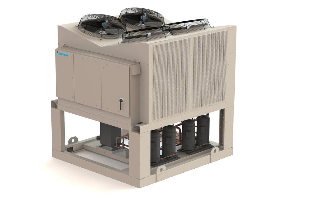
2 Contents Introduction Features and Benefits Application Considerations Sound Data Selection Procedure Performance Data Part Load Performance Data (60 Hz) Part Load Performance Data (50 Hz) Pressure Drop Data Physical Data - Packaged Units Dimensions - Packaged Lifting and Mounting Weights Electrical Data Field Wiring Diagram Electrical Data Options and Accessories Engineering Guide Specification Hazard Identification DANGER Dangers indicate a hazardous situation which will result in death or serious injury if not avoided. WARNING Warnings indicate potentially hazardous situations, which can result in property damage, severe personal injury, or death if not avoided. CAUTION Cautions indicate potentially hazardous situations, which can result in personal injury or equipment damage if not avoided. NOTE: Cover photo shows unit with coil grilles. Modbus 2014 Daikin Applied. Illustrations and data cover the Daikin Applied product at the time of publication and we reserve the right to make changes in design and construction at anytime without notice.


3 Introduction Introduction Air Cooled Chiller Products Air-Cooled Scroll Compressor Chiller Model AGZ-B RT AGZ-E AGZ-D Air-Cooled Scroll Compressor Chiller Model AGZ-E RT Model AGZ-D RT Remote Evaporator and Pump Package options available Air-Cooled Screw Compressor Chiller Model AGS RT Pathfinder Air-Cooled Screw Compressor Chiller Model AWS RT Standard, High, and Premium Efficency VFD and Remote Evaporator options available The AGZ family of air-cooled scroll chillers continues the Daikin Applied legacy of high quality, high efficiency, latest technology and quiet operation. These features make the AGZ family the best overall value in air-cooled packaged chillers available today. The AGZ-E series offers a wide selection of units from 30 to 70 tons with dual refrigerant circuits available as packaged units, with remote evaporators or with an optional pump package. Efficient Operation The AGZ units utilize environmentally acceptable R-410A refrigerant and meet the performance requirements of ASHRAE Standard 90.1 for efficiency. Excellent part-load performance is achieved with four or six scroll compressors. High overall efficiency = lower annual energy costs. RapidRestore and Fast Loading Technology When power has been interrupted, the AGZ-E has the capability to restore cooling quicly making it ideal for mission critical buildings, data centers, healthcare facilities, and manufacturing processes. After a power loss duration of up to 180 seconds, the time for an AGZ-E chiller restart is less than 125 seconds with the chiller reaching full load within 220 seconds from power restoration. Compact Size Compact models with a small footprint continues to be a primary design feature. The coil design and canted fan deck allow close spacing to walls and other units. These attributes lower installation cost and are excellent for replacement jobs. Application Flexibility AGZ-E units are available as packaged chillers or with remote evaporators. Information on remote evaporator models and factory-installed pump packages can be found in a separate installation manual available on Quiet Operation The AGZ units live up to the Daikin Applied reputation for low operating sound levels and make these chillers "neighborhood friendly. Full load sound pressure levels as low as 60dB without insulation. LEED Points Developed by the U.S. Green Building Council (USGBC) in 1998, Leadership in Energy and Environmental Design (LEED ) is an internationally recognized certification program and intends to provide building owners and operators a consistent structure for identifying and implementing practical and measurable green building design, construction, operations and maintenance solutions. For building owners who want to pursue LEED Green Building Certification, the AGZ-E series of air-cooled chillers does qualify for the Energy and Atmosphere Credit 4, Enhanced Refrigerant Management worth 2 points. CAT

4 Features and Benefits Chiller Nomenclature A G Z XXX E H Air-Cooled Global Design Scroll Compressor Nominal Tons Features and Benefits Unit Design Features Daikin AGZ air-cooled chillers are a product of our commitment to offer quiet, reliable, energy efficient equipment, incorporating high quality compressors, and innovative packaging. Construction AGZ chillers are factory-assembled and mounted on a heavygauge steel base. The base rails, supports and cabinetry are powder-coat painted for long life. The base distributes the unit weight for roof loading. Their small footprint allows smaller mounting pads or support structures and is a plus for retrofit or replacement applications. Compressors Reliable hermetic scroll compressors with cast iron scrolls and three Teflon impregnated bearings are used on the AGZ-E chillers to promote longevity. Each model has four steps of capacity modulation. One to four compressors can run, depending on the load of the system, resulting in excellent part-load efficiency and reduced annual operating costs. Features include motor temperature protection, scroll temperature protection, missing phase protection, reverse phase protection, low control circuit voltage protection, short cycling detection and alert, modbus communication to system controller, operational and fault history storage, and LED status display. Evaporator Models AGZ-030 through AGZ-070 The evaporator is a compact, high efficiency, dual circuit, brazed plate-to-plate type heat exchanger consisting of parallel stainless steel plates. These heat exchangers provide excellent heat exchange efficiency in a compact footprint and are especially attractive for smaller capacity units. Application H = Standard Packaged B = Remote Evaporator Design Vintage The water side working pressure is 653 psig (4502 kpa). Evaporators are designed and constructed according to, and listed by, Underwriters Laboratories (UL). Remote Evaporator (Option) Units with the optional remote evaporator will have the evaporator shipped separately for field mounting and piping to the outdoor unit. Condenser Coils Condenser coils are all aluminum alloy microchannel design with a series of flat tubes containing multiple, parallel flow microchannels layered between the refrigerant manifold piping. A variety of optional coil materials and coatings are available so that the unit can be constructed to meet almost any environment. Options include: copper tube/aluminum fins copper tube/copper fins copper tube/aluminum Black-fins ElectroFin coating can be applied to any coil option See Application Considerations for discussion of environmental factors related to material and coating options. Figure 1: Microchannel Coil 4 CAT 624-2

5 Features and Benefits Condenser Fans and Motors Multiple direct-drive, dynamically balanced propeller fans operate in formed venturi openings at low tip speeds for maximum efficiency and minimum noise and vibration. A heavy-gauge vinyl-coated fan guard protects each fan. Each condenser fan motor (including the optional VFD fan motor) is Totally Enclosed Air Over (TEAO), heavy-duty, 3- phase with permanently lubricated ball bearings and inherent overload protection. These motors are designed specifically for outdoor use. The fan deck is canted inward and directs discharge air toward the center of the unit, reducing the tendency to spill over the sides and into the coil, reducing capacity. This feature, combined with the coil design allows closer unit spacing than most competitors. The result is a smaller installation footprint and reduced first cost. The external condenser coils are fitted with a standard wire mesh guards to protect the coil from damage. Optional louvers create an attractive appearance that can eliminate the need for screening walls. Figure 2: AGZ-E with Optional Full Louver Package The MicroTech III controller's design will not only permit the chiller to run more efficiently, but will also simplify troubleshooting if a system failure occurs. Every MicroTech III controller is programmed and tested prior to shipment to help provide a trouble-free start-up. Operator-friendly The MicroTech III control menu structure is separated into four distinct categories that provide the operator or service technician with a full description of current unit status, control parameters, and alarms. Security protection helps prevent unauthorized changing of the setpoints and unit control parameters. MicroTech III control continuously performs important selfdiagnostic checks while monitoring system temperatures, pressures and protection devices. It will automatically shutdown a compressor, a refrigerant circuit or the entire unit if a fault occurs. The cause of the shutdown will be retained in memory and can be easily displayed in plain English or metric units for operator review. In addition to displaying alarm diagnostics, the MicroTech III chiller controller also provides the operator with a warning of pre-alarm conditions. Alarm notification data can also be passed to a BAS through an optional communication module. Staging The scroll compressors are staged on and off as a function of leaving chilled water temperature. Lead/lag is automatic and switched based on starts and operating hours. Control System The MicroTech III advanced DDC chiller controller surpasses all other microprocessor-based chiller control systems available today. This powerful, user-friendly control system provides the flexibility and performance needed for either stand-alone unit operation or the controller can be easily tied into your building automation system of choice using the Daikin Open Choices feature. Open Choices allows you to choose from open standard protocols such as BACnet, Modbus and LonWorks to communicate easily with the building automation system that best meets your facility requirements. These optional communications modules are available factory installed or can be easily field installed. Equipment Protection The unit is protected in three ways: 1 alarms that shut the unit down and require manual reset to restore unit operation, 2 alarms that shut the unit down and then restart automatically (do notrequire manual restart), and 3 limit alarms that reduce unit capacity in response to some out-of-limit condition. Shut down alarms activate an alarm signal that can be exported to a remote location. Limit alarms activate a light on the controller and do not trigger a remote alarm. Building Automation System (BAS) Interface The following BAS protocols are supported: BACnet/IP BACnet MS/TP LonWorks (FTT-10A) Modbus CAT

6 Features and Benefits Optional Remote Interface Panel In addition to the unit-mounted user interface provided with MicroTech III controls, the AGZ chillers can be individually equipped with a remote user interface. It provides convenient access to unit diagnostics and control adjustments without having to access a rooftop or outdoor location. One remote panel can be connected to up to eight chillers. Features Each remote user interface is similar to its unit-mounted counterpart and offers the same functionality and display: Three buttons and a navigating wheel with a 8 line by 30-character display format. Digital display of messages in English language. All operating conditions, system alarms, control parameters and schedules are monitored. Can be wired up to 2,300 feet (700 meters) from the unit for flexibility in placing each remote user interface within your building. Benefits Allows you to access the user interface for each unit from one location, inside the building. Users need to learn one format because the remote user interface is identical to the unit-mounted version. No additional field commissioning is required for the remote user interface. Can be retrofit after unit installation. Is fully compatible with the optional BAS communication modules. The current manual for the MicroTech III Remote User Interface isavailable on Figure 3: Optional Pump Package Schematic Optional Pump Package The on-board, integrated chilled water pump package provides important benefits: Simplify the chilled water system design and installation Provide installation savings by reducing field piping, wiring and control costs Save valuable floor space inside the building. Reduce project engineering content Greatly reduce pump operating cost with the optional variable flow pump VFD Standard Components Single Pump: Model 4380 single spring inside seal, vertical, in-line, radially split-case pump, serviceable without breaking pipe connections. The motor and pump rotating assembly can be serviced without removing the pump casing from the line. Dual Pumps in a Single Casting: Model 4392 single-spring inside-seal vertical, in-line, radially split-case pumps, mounted in a common casing with a common inlet connection and outlet connection and including a flapper valve to prevent recirculation when only one pump is operating. An isolation valve is included that allows one pump to operate when the other is removed. The pumps are designed for duty/standby, not parallel operation. All information and performance curves for the single pump arrangement (Model 4380) can be used for the dual pump arrangement (Model 4392). The package is also is equipped with a "Y" type inlet strainer, a combination triple-duty outlet valve having a discharge shutoff valve, check valve, and flow throttling valve, a combination suction guide with flow stabilizing outlet vanes and stainless steel strainer with a disposable fine-mesh start-up strainer, a flow switch mounted and wired, factory power and control wiring, interconnecting piping and insulation of all cold surfaces. Various tank and connection options are available for field mounting. 6 CAT 624-2
7 Features and Benefits Optional Variable Flow VFD The operating cost savings resulting from using variable chilled water flow via a pump VFD is well known. In the past, however, its usage has been somewhat limited by the cost and uncertainty of field installing the required system pressure differential sensors. Daikin Applied can now offer an innovative variable chilled water flow system completely self-contained within the pump package by simply ordering the optional pump VFD-no external sensors required. In addition to the sensorless operation, there are three other selectable operating modes: BAS Input: The pump speed and system flow will be controlled from a customer-supplied BAS input signal. Remote Sensor Control: The VFD is wired to a pressure sensor mounted in the chilled water piping system. This is the standard VFD control when a sensorless VFD is not used. Locally Selected Constant Speed Control: Provides manual control of the pump speed, overriding any current automatic speed control. Consult the current version of the installation manual for additional detailed information. It is available from the local Daikin Applied sales office or on Operating and Standby Limits Table 1: Operating Limits Maximum standby ambient temperature Maximum operating ambient temperature -with optional high ambient package (see information under High Ambient Operation page 12) Minimum operating ambient temperature (standard control) -with optional low ambient control (see information under Low Ambient Operation page 12) Leaving chilled water temperature Leaving chilled fluid temperatures (with anti-freeze) - Note that in cases of high ambient temperature, the lowest leaving water temperature settings may be outside of the chiller operating envelope; consult Daikin Tools to ensure chiller is capable of the required lift. Operating chilled water delta-t range Maximum evaporator operating inlet fluid temperature Maximum evaporator non-operating inlet fluid temperature 130 F (55 C) 105 F (40 C) 125 F (52 C) 32 F (0 C) -10 F (-23 C) 40 F to 65 F (2 C to 18 C) 15 F to 65 F (-9 C to 18 C) 6 F to 16 F (3.3 C to 8.9 C) 81 F (27 C) 100 F (38 C) CAT

8 Application Considerations Application Considerations Unit Placement AGZ units are for outdoor applications and can be mounted either on a roof or at ground level. For roof mounted applications, install the unit on a steel channel or I-beam frame to support the unit above the roof. For ground level applications, install the unit on a substantial base that will not settle. Use a one-piece concrete slab with footings extended below the frost line. Be sure the foundation is level within 0.5 (13mm) over its length and width. The foundation must be strong enough to support the weights listed in the Physical Data Tables beginning on page 25. Service Clearance Sides: Minimum of 4 feet (1.22 m) Control panel end: Minimum of 4 feet Opposite control panel: Minimumof 4 feet Spacing Requirements In general, with a small performance penalty in some cases, AGZ-E units can be spaced at four feet from other units or a wall. Curves on the following pages give the minimum clearance for different types of installations and also capacity reduction and power increase if closer spacing is used. Case 1: Wall on One Side In this case a solid wall up to 24-feet is considered and a minimumof 4 feet should be maintained on all sides. (For walls higher than 24 ft., use the 24-foot values.) Also use this case for an adjacent building. For perforated screening walls, use Case 4. Figure 4: Wall on One Side of Unit Air Clearance Daikin Applied's advanced W coil design and open airpassage ends allow very close unit spacing and a small installation footprint. The AGZ-E fans are canted inward and reduce recirculation by directing discharge air to the center of the unit, reducing the tendency to flow outward and spill over into the coil inlet. Sufficient clearance must be maintained between the unit and adjacent walls or other units to allow the required unit air flow to reach the coils. Failure to do so will result in a capacity reduction and an increase in power consumption. No obstructions are allowed above the unit at any height. Case 2: Two Units, Side-by-Side For models AGZ 030E-070E: use 4 feet between units. Figure 5: Case 2 - Two units side by side 8 CAT 624-2
9 Application Considerations Case 3: Three or More Units, Side-by-Side Maintain a minimum of 6-feet on all sides. For more than three units, allow an additional 2-feet clearance between units. Figure 6: Case 3-3 units side by side Case 5: Pit Installation Pit installations can cause operating problems resulting from air recirculation and restriction and require care that sufficient air clearance is provided, safety requirements are met and service access is provided. Pit covers must have abundant open area at least equal to the chiller footprint.a solid wall surrounding a unit is substantially a pit and this data should be used. Steel grating is sometimes used to cover a pit to prevent accidental falls or trips into the pit. The grating material and installation design must be strong enough to prevent such accidents, yet provide abundant open area to avoid recirculation problems. Have any pit installation reviewed by the Daikin Applied sales representative prior to installation to ensure it has sufficient air-flow characteristics and approved by the installation design engineer to avoid risk of accident. Figure 8: Case 5 - Pit Installation Case 4: Open Screening Walls Decorative screening walls are often used to help conceal a unit either on grade or on a rooftop. Design these walls such that the combination of their open area and distance from the unit do not require performance adjustment. It is assumed that the wall height is equal to or less than the unit height when mounted on its base support. If the wall height is greater than the unit height, see Case 5, Pit Installation, page 9. The distance from the sides of the unit to the side walls must be sufficient for service, such as opening control panel doors. For uneven wall spacing, the distance from the unit to each wall can be averaged providing no distance is less than 4 feet. Values are based on walls on all four-sides. Figure 7: Case 4 Adjustment Factor Figure 9: Case 5 Adjustment Factors (AGZ030E-070E) Full Load Capacity Reduction (AGZ ) Wall Free Area vs. Distance 3.0 % Capacity Reduction Distance from Wall to Unit (ft) % Open Wall Area AGZ Depth of Pit (ft) Distance = 4 ft Distance = 5 ft Distance = 6 ft Power Increase (AGZ ) % Pow er Increase Depth of Pit (ft) Distance Distance = 5 ft Distance = 4 ft = 6 ft CAT


10 Application Considerations Chilled Water Piping IMPORTANT: Piping design must be provided by a qualified Architect or Systems HVAC Design Engineer familiar with piping design, as well as local codes and regulations. The manufacturer recommendations provided here are to be used as a general guide, but do not replace system design by a qualified professional. Follow all instructions and recommendations for Chilled Water Piping in the current version of the installation manual available on Design the water piping so the chilled water circulating pump discharges into the evaporator inlet. A cleanable perforated basket strainer with inch perforations and 41% open area must be installed in the water line just prior to the inlet of the evaporator. The strainer may be factory installed or is available as field-installed kit. See Optional Inlet Strainer below for more information. A water flow switch must be installed in the horizontal piping of the supply (evaporator outlet) water line to avoid evaporator freeze-up under low or no flow conditions. The flow switch may be ordered as a factory-installed option, a field-installed kit, or may be supplied and installed in the field (See Options and Accessories, page 38 for more information). Vibration eliminators are recommended in both the supply and return water lines. Pressure gauges must be installed in the inlet and outlet water lines to the evaporator. Insulate chilled water piping to reduce heat loss and prevent condensation. Chillers not running in the winter should have their water systems thoroughly drained to protect against freezing. If the chiller operates year-round, or if the system is not drained for the winter, protect the chilled water piping exposed to outdoor temperature against freezing. Wrap the lines with a heater cable and add appropriate amount of glycol to further protect the system. Optional Inlet Strainer An inlet water strainer kit is available as a factory or fieldinstalled accessory, sized per Table 2 and with the pressure drop show in Figure 11. This pressure drop must be accounted for in the total system pressure drop. The kit consists of: (1) Y-type strainer with 304 stainless steel 40 or 41% open area perforated basket, Victaulic pipe connections and strainer cap (1) Extension pipe with (2) Schrader fittings that can be used for a pressure gauge and thermal dispersion flow switch. The pipe provides sufficient clearance from the evaporator for strainer basket removal. (1) ½-inch blowdown valve (2) Victaulic clamps Figure 10: Factory Installed Strainer Table 2: Strainer Data AGZ Model Figure 11: Strainer Pressure Drop Water Flow Limitations Constant Flow Strainer Size (in.) Strainer Plus Pipe Length (in.) Strainer Weight (lbs) The evaporator flow rates and pressure drops shown on page page 24 are for full load design purposes. The maximum flow rate and pressure drop are based on a 6 F temperature drop. Avoid higher flow rates with resulting lower temperature drops to prevent potential control problems resulting from very small control bands and limited start up/shut off temperature changes. The minimum flow and pressure drop is based on a full load evaporator temperature drop of 16 F. Evaporator flow rates below the minimum values can result in laminar flow causing freeze-up problems, scaling and poor control. Flow rates above the maximum values will result in unacceptable pressure drops and can cause excessive erosion, potentially leading to failure. 10 CAT 624-2

11 Application Considerations Evaporator Variable Flow Reducing evaporator flow in proportion to load can reduce system power consumption. The rate of flow change should be a maximum of 10 percent of the flow per minute. For example, if the maximum design flow is 200 gpm and it will be reduced to a flow of 140 gpm, the change in flow is 60 gpm. Ten percent of 200 gpm equals 20 gpm change per minute, or a minimum of three minutes to go from maximum to desired flow. Do not reduce flow lower than the minimum flows listed in the evaporator pressure drop section, page 24. The water flow through the evaporator must remain between the minimum and maximum values listed on page 24. If flow drops below the minimum allowable, large reductions in heat transfer can occur. If the flow exceeds the maximum rate, excessive pressure drop and tube erosion can occur. Figure 12: Typical Piping, Brazed-Plate Evaporator (models AGZ030E-070E) Typical Piping Piping for units with brazed-plate evaporators must have a drain and vent connection provided in the bottom of the lower connection pipe and to the top of the upper connection pipe respectively, see Figure 12. These evaporators do not have drain or vent connections due to their construction. System Water Volume Considerations All chilled water systems need adequate time to recognize a load change, respond to the change and stabilize to avoid undesirable short cycling of the compressors or loss of temperature control. In air conditioning systems, the potential for short cycling usually exists when the building load falls below the minimum chiller plant capacity or on close-coupled systems with very small water volumes. Some of the things the designer should consider when looking at water volume are the minimum cooling load, the minimum chiller plant capacity during the low load period and the desired cycle time for the compressors. Assuming that there are no sudden load changes and that the chiller plant has reasonable turndown, a rule of thumb of gallons of water volume equal to two to three times the chilled water gpm flow rate is often used. A storage tank may have to be added to the system to reach the recommended system volume. Evaporator Freeze Protection Evaporator freeze-up can be a concern in the application of aircooled water chillers in areas experiencing below freezing temperatures. To protect against freeze-up, insulation and an electric heater are furnished with the evaporator. Models 030 through 070 have an external plate heater and thermostat. This helps protect the evaporator down to -20 F (-29 C) ambient air temperature. Although the evaporator is equipped with freeze protection, it does not protect water piping external to the unit or the evaporator itself if there is a power failure or heater burnout, or if the chiller is unable to control the chilled water pumps. Use one of the following recommendations for additional protection: 1 If the unit will not be operated during the winter, drain evaporator and chilled water piping and flush with glycol. 2 Add a glycol solution to the chilled water system to provide freeze protection. Burst protection should be approximately 10 F below minimum design ambient temperature. 3 The addition of thermostatically controlled heat and insulation to exposed piping. The evaporator heater cable is factory wired to the 115 volt circuit in the control box. This power should be supplied from a separate source to maximize unit protection, but it can be supplied from the control circuit. Operation of the heaters is automatic through the ambient sensing thermostat that energizes the evaporator heaters for protection against freezeup. Unless the evaporator is drained in the winter or contains an adequate concentration of anti-freeze, the disconnect switch to the evaporator heater must not be open. CAT
12 Application Considerations Chilled Water Pump It is important that the chilled water pumps be wired to, and controlled by, the chiller's microprocessor. When equipped with optional dual pump output, the chiller controller has the capability to selectively send the signal to a pump relay (by others) to start pump A or B or automatically alternate pump selection and also has standby operation capability. The controller will energize the pump whenever at least one circuit on the chiller is enabled to run, whether there is a call for cooling or not. This helps ensure proper unit start-up sequence. The pump will also be turned on when the water temperature reaches 1 F below the Freeze Setpoint to help prevent evaporator freeze-up. Connection points are shown in the Field Wiring Diagram on page 34. CAUTION Adding glycol or draining the system is the recommended method of freeze protection. If the chiller does not have the ability to control the pumps and the water system is not drained in temperatures below freezing, catastrophic evaporator failure may occur. Failure to allow pump control by the chiller may cause the following problems: 1 If any device other than the chiller attempts to start the chiller without first starting the pump, the chiller will lock out on the No Flow alarm and require manual reset. 2 If the chiller evaporator water temperature drops below the Freeze setpoint the chiller will attempt to start the water pumps to avoid evaporator freeze. If the chiller does not have the ability to start the pumps, the chiller will alarm due to lack of water flow. 3 If the chiller does not have the ability to control the pumps and the water system is not to be drained in temperatures below freezing, the chiller may be subject to catastrophic evaporator failure due to freezing. The freeze rating of the evaporator is based on the immersion heater and pump operation. The immersion heater itself may not be able to properly protect the evaporator from freezing without circulation of water. Temperature and Water Flow Limitations Evaporator flow rates below the minimum values can result in laminar flow causing freeze-up problems, scaling and poor control. Flow rates above the maximum values will result in unacceptable pressure drops and can cause excessive erosion, potentially leading to failure. Low Ambient Operation Compressor staging is adaptively determined by system load, ambient air temperature, and other inputs to the MicroTech III control. The standard minimum ambient temperature is 32 F (0 C). A low ambient option with fan VFD allows operation down to -10 F (-23 C). The minimum ambient temperature is based on still conditions where the wind is not greater than five mph. Greater wind velocities will result in reduced discharge pressure, increasing the minimum operating ambient temperature. Field installed hail/wind guards are available to allow the chiller to operate effectively down to the ambient temperature for which it was designed. High Ambient Operation AGZ-E units for high ambient operation (105ºF to 125 F, 40.1 C to 51.7 C) require the addition of the optional high ambient package that includes a small fan with a filter in the air intake to cool the control panel. All units with the optional VFD low ambient fan control automatically include the high ambient option. 12 CAT 624-2

13 Application Considerations Condenser Coil Options and Coating Considerations The standard coils on the AGZ-E chiller are an all aluminum alloy microchannel design with a series of flat tubes containing multiple, parallel flow microchannels layered between the refrigerant manifolds. The microchannel coils are designed to withstand hour acidified synthetic sea water fog (SWAAT) test (ASTM G85-02) at 120 F (49 C) with 0% fin loss and develop no leaks. The all-aluminum microchannel coils provide superior longevity and durability for noncorrosive applications. Should the standard microchannel coil not meet the corrosion requirements for the application, additional coil options are available. Aluminum fin/copper tube coils consist of 3/8 inch (10mm) seamless copper tubes mechanically bonded into plate-type aluminum fins. The fins have full drawn collars to completely cover the tubes. The aluminum fin/copper tube option provides excellent durability in non-corrosive environments, and adds the benefit of ease of field repair. Since the fin and the tube materials are similar, the opportunity for galvanic corrosion is eliminated. The copper fin/copper tube option provides excellent longevity in marine environments; however this option is not well suited for industrial or chemical atmospheric contamination. ElectroFin TM coil coating is a water-based extremely flexible and durable epoxy polymer coating uniformly applied to all coil surfaces through a multi-step, submerged electrostatic coating process. ElectroFin TM condenser coils provide a hour salt spray resistance per ASTM B117-90, applied to both the coil and the coil frames. The ElectroFin TM coated coils also receive a UV-resistant urethane top-coat to provide superior resistance to degradation from direct sunlight. This coil coating option provides the best overall protection against corrosive marine, industrial or combined atmospheric contamination. This coating option may be applied to any of the untreated coil options offered, to provide excellent longevity and resistance to corrosion. Figure 13: ElectroFin Coil Coating.. BlackFin TM coils include aluminum fins pre-coated with a durable phenolic epoxy coating. In addition to providing a durable coating on the fin material, the BlackFinTM coils provide and epoxy barrier between the aluminum fin stock and the copper tube, to prevent the galvanic corrosion that can occur between the dissimilar metals. This option will provide a hour salt spray rating per ASTM B The BlackFinTM option provides an economical solution for enhanced protection in mildly corrosive environments. Copper-fin coils consist of 3/8 inch (10mm) seamless copper tubes mechanically bonded into plate-type copper fins. The fins have full drawn collars to completely cover the tubes. Table 3: Coil/Coating Selection Matrix Coil Option Non-Corrosive 1 Unpolluted Marine 2 Industrial 3 Combined Marine- Industrial 4 Standard Microchannel Aluminum Fin/Copper Tube Copper Fin/Copper Tube BlackFin TM ElectroFin TM Note: 1.Non-corrosive environments may be estimated by the appearance of existing equipment in the immediate area where the chiller is to be placed. 2.Marine environments should take into consideration proximity to the shore as well as prevailing wind direction. 3.Industrial contaminants may be general or localized, based on the immediate source of contamination (i.e. diesel fumes due to proximity to a loading dock). 4.Combined marine-industrial are influenced by proximity to shore, prevailing winds, general and local sources of contamination. CAT

14 Sound Data Data Sound levels can be as important as unit cost and efficiency. The inherently quiet scroll compresors used in model AGZ-E chillers are coupled with precision engineering for industryleading sound levels. Background AHRI has established standards to provide uniform methods for the determination of the sound levels of equipment. For large air-cooled chillers, it is AHRI Standard 370, Sound Ratings of Large Outdoor Refrigeration and Air-Conditioning Equipment. Data contained in this section are in accordance with this standard. A Weighting Sound values may be represented several ways. One of the more common forms is the A weighted value, which adds or subtracts a specific amount to each center band frequency, then logarithmically adds the values to establish a single value. The A scale is used to represent how the human ear receives sound. The amount added in each frequency band directly corresponds to how sensitive the human ear is to each frequency. Table 4: A Scale Relative Response to Human Ear Frequency, f, in Hz K 2K 4K 8K 16K db(a) Sound Pressure Levels - Full Load Sound pressure is the sound level that can be measured at some distance from the source. Sound presure varies with distance from the source and depends on the surroundings. For example, a brick wall (a reflective surface) located 10 feet from a unit will affect the sound pressure measurements differently than a brick wall at 20 feet. Sound pressure is measured in decibels (db). All sound pressure data in the following pages are considered typical of what can be measured in a free field with a handheld sound meter, in the absence of any nearby reflective surfaces except the floor under the unit. Sound pressure levels are measured at 30 feet (10 meters) from the side of the unit at 100% load and standard AHRI conditions (per AHRI standard 550/ ) of 95 F (35 C) ambient air temperature and 44 F (7 C) leaving evaporator water temperatures for aircooled units. Sound Power Levels Sound power is a calculated quantity and cannot be measured directly like sound pressure. Sound power is not dependent on the surrounding environment or distance from the source, as is sound pressure. It can be thought of as basic sound level emanating from the unit without consideration of distance or obstructions. Measurements are taken over a prescribed area around the unit and the data is mathematically calculated to give the sound power, db.acoustical consultants sometimes use sound power octave band data to perform a detailed acoustical analysis. Figure 14: Sound Power vs. Sound Pressure The data in the following tables present sound power levels per AHRI Standard 370, "Sound Rating of Large Outdoor Refrigerating and Air Conditioning Equipment". This standard was developed to establish uniform methods of determining the sound power radiated by large outdoor equipment. Measurements are taken over a prescribed area around the unit and the data is mathematically calculated to give the sound power, db. Sound Reduction due to Distance from the Unit The distance between a source of sound and the location of the sound measurement plays an important role in minimizing sound problems. The equation below can be used to calculate the sound pressure level at any distance if the sound power is known. Results for typical distances are tabulated in Table 5. Table 5: db Conversion of Sound Power to Pressure Distance from Sound Source ft. (m) DB Reduction from Sound Power at the Source to Sound Pressure at Referenced Distance Q=2 Q=4 30 (9) (15) (23) (30) (46) (61) (91) CAT 624-2
15 Sound Data Figure 15: Q Reflective Sources Illustration reflection from the source. For example, a unit sitting on a flat roof or ground with no other reflective surfaces or attenuation due to grass, snow, etc., between source and receiver: Q=2. Sound pressure can be calculated at any distance from the unit if the sound power is known, using the equation: Lp=Lw-(20 log r) + (10 log Q) Where: Lp = sound pressure Lw = sound power r = distance from unit in feet Q = directionality factor With Q=1, Unit suspended in space (theoretical condition), the equation simplifies to: Lp = Lw - (20log r) -0.5 With Q=2, for a unit sitting on a flat roof or ground with no adjacent vertical wall as a reflective surface, the equation simplifies to: Lp = Lw - (20log r) With Q=4 for a unit sitting on a flat roof or ground with one adjacent vertical wall as a reflective surface, the equation simplifies to: Lp = Lw - (20log r) The equations are reduced to table form in Table 5 for various distances and the two most usual cases of "Q" type of location. Sound Data Notes 1 Octave band readings are flat db, overall is A-weighted. Another way of determining the effect of distance is to work from sound pressure only. "Q", the directionality factor, is a dimensionless number that compensates for the type of sound 2 Sound pressure data taken at 30ft (9m) from side of unit; Q=2, unit on flat surface with no adjacent wall. CAT
16 Sound Data Table 6: 60 Hz Sound Power without Sound Insulation Model Num be r of Compressors Num be r of Fans Octave Band at Center Frequency Overall A-Weighted Table 7: 60 Hz Sound Pressure without Sound Insulation (at 30 feet from side of unit) Model Num be r of Compressors Num be r of Fans Octave Band at Center Frequency, 30 ft. from unit Overall A-Weighted Table 8: 60 Hz Sound Power with Sound Insulation Model Num be r of Compressors Num be r of Fans Octave Band at Center Frequency Overall A-Weighted Table 9: 60 Hz Sound Pressure with Sound Insulation (at 30 feet from side of unit) Model Num be r of Compressors Num be r of Fans Octave Band at Center Frequency, 30 ft. from unit Overall A-Weighted CAT 624-2
17 Sound Data Table 10: 50 Hz Sound Power without Sound Insulation Model Num be r of Compressors Num be r of Fans Octave Band at Center Frequency Overall A-Weighted Table 11: 50 Hz Sound Pressure without Sound Insulation (at 30 feet from side of unit) Model Num be r of Compressors Num be r of Fans Octave Band at Center Frequency, 30 ft. from unit Overall A-Weighted Table 12: 50 Hz Sound Power with Sound Insulation Model Num be r of Compressors Num be r of Fans Octave Band at Center Frequency Overall A-Weighted Table 13: 50 Hz Sound Pressure with Sound Insulation (at 30 feet from side of unit) Model Num be r of Compressors Num be r of Fans Octave Band at Center Frequency, 30 ft. from unit Overall A-Weighted CAT
18 Selection Procedure Selection Procedure AGZ-E chillers are ideal for a wide range of applications and operating conditions. Selection with Inch-Pound (I-P) units The performance tables beginning on page 29 cover the range of leaving evaporator water temperatures and outside ambient temperatures included under the current AHRI Standard 550/ 590. The tables are based on a 10 F (5.5 C) temperature drop through the evaporator. Adjustment factors for applications having other than a 10 F (5.5 C) drop can be found in Table 18, page 28. The minimum leaving chilled water temperature setpoint without glycol is 40 F (4ºC). For brine selections, see Table 16 and Table 17 on page 28 for glycol adjustment factors. Ratings are based on a ft2 x hr x ºF/Btu fouling factor in the evaporator at sea level operation. For other fouling factors, different Delta-Ts, or altitude correction factors see Table 18, page 28. For applications outside the catalog ratings, please contact your local Daikin Applied sales representative. Selection example Given: 50 tons minimum 95 F ambient temperature 120 gpm, 54ºF to 44 F chilled water evaporator fouling factor 1 From Table 19, page 29, an AGZ055E at the given conditions will produce 51.8 tons with a unit kw input of 59.6 and a unit EER of Use the following formula to calculate any unknown elements (water only): tons 24 = ΔT ( F) gpm 3 Determine the evaporator pressure drop. Using Figure 28, page 45, enter at about 124 gpm and follow up to the AGZ 055 line intersect. Read horizontally to obtain an evaporator pressure drop of 13 feet of water. Selection example using ethylene glycol Given: 44 tons minimum 95 F ambient air temperature 54 F - 44 F chilled water temperature evaporator fouling factor Protect from freezing down to 0 F 1 From Table 16, page 28, select an ethylene glycol concentration of 40% to protect against freezing at 0 F. 2 At 40% ethylene glycol, the adjustment factors are: Capacity = kw = GPM = Pressure Drop = Select the AGZ 050E from Table 19, page 29 and correct with 40% ethylene glycol factors. 4 Correct capacity = X 48.3 tons = 47.3 tons 5 Correct kw = X 54.6 kw = 54.2 kw 6 Calculate chilled water flow: Water corrected capacity = 47.3 tons x 24 / 10 F = gpm Glycol flow (at 40% solution) = x gpm = gpm Determine the evaporator pressure drop. Using Figure 28, page 45, enter at gpm (water) and follow up to the AGZ050 line intersect. Read horizontally to obtain an evaporator pressure drop of 17 feet. Correct the pressure drop for 40% solution = x 17 feet = 26.5 feet for ethylene glycol using Table 16, page 28. Selection with SI units Use the SI tables and the same procedures as with I-P units. Use the following formula to calculate any missing elements (water only): kw l = ΔT ( C) s 18 CAT 624-2
19 Performance Data Performance Data Note: Due to different performance characteristics, the factors shown in the following tables are for brazed-plate evaporators (AGZ030E - 070E). Note: Derate factors for models with remote evaporators can be found in the current installation manual at Ethylene & Propylene Glycol Factors AGZ units can operate with a leaving chilled fluid temperature range of 20 F (-6 C) to 60 F (10 C). A glycol solution is required when leaving chilled fluid temperature is below 40 F (4.6 C). The use of glycol will reduce the performance of the unit depending on concentration. Note: Ethylene and propylene glycol ratings are outside the scope of the current AHRI Standard 550/590 certification program. Table 14: Ethylene Glycol Correction Factors Freeze Point % E.G. F C Capacity Power Flow PD Table 15: Propylene Glycol Correction Factors Freeze Point % P.G. F C Capacity Power Flow PD Altitude Correction Factors Performance tables are based at sea level. Elevations other than sea level affect the performance of the unit. The decreased air density will reduce condenser capacity consequently reducing the unit's performance. For performance at elevations other than sea level refer to Table 16. Table 16: Capacity and Power Derates Altitude Sea Level 2000 feet 4000 feet 6000 feet Water Delta T Fouling Factor (0.0176) (0.044) (0.132) (0.308) F C C a p. P o we r C a p. P o we r C a p. P o we r C a p. P o we r Evaporator Temperature Drop Factors Performance tables are based on a 10 F (5 C) temperature drop through the evaporator. Adjustment factors for applications with temperature ranges from 6 F to 16 F (3.3 C to 8.9 C) are in Table 16. Temperature drops outside this 6 F to 16 F (3.3 C to 8.9 C) range can affect the control system's capability to maintain acceptable control and are not recommended. AHRI Certification Performance on all 60Hz standard packaged models is certified per AHRI standard 550/590. Chillers with optional remote evaporator are outside the scope of the AHRI rating program. CAT
20 Performance Data Table 17: 60 Hz Full Load Performance Data (IP) Unit Size Hz LWT (ºF) Tons Am bient Tem perature (ºF) Pow er (kw) EER Tons Pow er (kw) EER Tons Pow er (kw) EER Tons Pow er (kw) EER Tons Pow er (kw) EER 20 CAT 624-2
21 Performance Data Table 18: 50 Hz Full Load Performance Data (IP) Unit Size Hz LWT (ºF) Tons Am bient Tem perature (ºF) Pow er (kw) EER Tons Pow er (kw) EER Tons Pow er (kw) EER Tons Pow er (kw) EER Tons Pow er (kw) EER CAT
22 Part Load Performance Data (60 Hz) Part Load Performance Data (60 Hz) Table 19: 60 Hz Part Load Performance Data (IP) Model % Load Tons kw EER IPLV CAT 624-2
23 Part Load Performance Data (50 Hz) Part Load Performance Data (50 Hz) Table 20: 50 Hz Part Load Performance Data (IP) Model % Load Tons kw EER IPLV CAT
24 Pressure Drop Data Pressure Drop Data Figure 16: Pressure Drop Curves 100 A B C D E F G H I A I BC E D FG H D p (ft) I E BC D FG H 10 A I E BC D FG H A Flow Rate (gpm) Table 21: Pressure Drop Data Variable Flow System Only Minimum Flow Rate Fixed Flow System Only Minimum Flow Rate Fixed and Variable Flow Systems Nominal Flow Rate Maximum Flow Rate Curve IP SI IP SI IP SI IP SI Model Ref. GPM DP ft. lps DP kpa GPM DP ft. lps DP kpa GPM DP ft. lps DP kpa GPM DP ft. lps DP kpa A 30E B 35E C 40E D 45E E 50E F 55E G 60E H 65E I 70E CAT 624-2
25 Physical Data - Packaged Units Physical Data - Packaged Units Table 22: Physical Data - AGZ030E - AGZ040E AGZ-E (Microchannel Packaged Chiller) Physical Data AGZ030E AGZ035E AGZ040E CIRCUIT 1 CIRCUIT 2 CIRCUIT 1 CIRCUIT 2 CIRCUIT 1 CIRCUIT 2 BASIC DATA Unit AHRI tons (kw) - See Note (98.8) 34.9 (122.7) 39.2 (137.9) Unit Operating Charge lbs (kg) - Sealed Filter Drier 14 (6.4) 14 (6.4) 14 (6.4) 14 (6.4) 19 (8.6) 19 (8.6) - Replaceable Core Filter Drier 16 (7.3) 16 (7.3) 16 (7.3) 16 (7.3) 21 (9.5) 21 (9.5) Unit Dimensions L x W x H, in. (m m ) Package Unit Operating Weight, lbs. (kg) Package Unit Shipping Weight, lbs (kg) Weight-Add for (Upper) Louvered Panels, lbs (kg) Weight-Add for (Lower) Louvered Panels, lbs (kg) COMPRESSORS, SCROLL, HERMETIC 94.4 x 88 x x 88 x x 88 x (2398 x 2235 x 2550) (2398 x 2235 x 2550) (2398 x 2235 x 2550) 2960 (1343) 2887 (1310) 2964 (1344) 2947 (1337) 2873 (1303) 2948 (1337) N/A N/A 167 (76) 144 (65) 144 (65) 144 (65) Nom inal HP 7.5 / / / / / / 10.0 Oil charge per Compressor, oz (g) 85 (2410) 85 (2410) 85 (2410) 85 (2410) 85 (2410) 85 (2410) Staging, 4 Stages (If Circuit is in Lead) MICROCHANNEL CONDENSER Coil Inlet Face Area, sq. ft. (sq. m.) 24.9 (2.3) 24.9 (2.3) 24.9 (2.3) 24.9 (2.3) 49.8 (4.6) 49.8 (4.6) Rows Deep/Fins Per Inch 1 / 21 1 / 21 1 / 21 1 / 21 1 / 21 1 / 21 CONDENSER FANS, DIRECT DRIVE PROPELLER TYPE # of Fans per Circuit - Fan Diameter in (mm) 4-30 (762) 4-30 (762) 4-30 (762) 4-30 (762) 4-30 (762) 4-30 (762) Fan Motor, hp (kw) Fan & Motor RPM Fan Tip Speed, fpm (m/s) Airflow, cfm (l/s ) 1.5 (1.1) (45) 34,000 (16047) 1.5 (1.1) (45) 34,000 (16047) 1.5 (1.1) (45) 40,400 (19,067) EVAPORATOR, BRAZED PLATE Evaporator, Model (1 Evaporator / 2 Circuits) Dry Weight lbs (kg) Water Volume, gallons (liters) Victaulic inlet/outlet conn. in. (mm) Max. Water Pressure, psi (kpa) Max. Refrigerant Pres s., ps i (kpa) ACH-230DQ-78H 84 (38.1) 2.0 (7.6) 2.5 (65) 653 (4502) 653 (4502) ACH-230DQ-86H 91 (41.3) 2.2 (8.4) 2.5 (65) 653 (4502) 653 (4502) ACH-230DQ-94H 98 (44.5) 2.4 (9.2) 2.5 (65) 653 (4502) 653 (4502) Note 1: Nominal capacity based on 95 F ambient air and 54 F/44 F water range. Note 2: For all 380V/60 & 575V/60 models, HP = 2.0. Note 3: Water connection shown is nominal pipe size. Note 4: Brazed plate evaporators do not have drain or vent connections integral to the heat exchanger. The connections must be installed in the field inlet and outlet piping as shown in Piping Section of IM 1100, available on CAT
26 Physical Data - Packaged Units Table 23: Physical Data - AGZ045E - AGZ055E AGZ-E (Microchannel Packaged Chiller) Physical Data AGZ045E AGZ050E AGZ055E CIRCUIT 1 CIRCUIT 2 CIRCUIT 1 CIRCUIT 2 CIRCUIT 1 CIRCUIT 2 BASIC DATA Unit AHRI tons (kw) - See Note (149.8) 48.3 (169.8) 51.8 (182.1) Unit Operating Charge lbs (kg) - Sealed Filter Drier 19 (8.6) 19 (8.6) 19 (8.6) 19 (8.6) 19 (8.6) 19 (8.6) - Replaceable Core Filter Drier 21 (9.5) 21 (9.5) 21 (9.5) 21 (9.5) 21 (9.5) 21 (9.5) Unit Dimensions L x W x H, in. (m m ) Package Unit Operating Weight, lbs. (kg) Package Unit Shipping Weight, lbs (kg) Weight-Add for (Upper) Louvered Panels, lbs (kg) Weight-Add for (Lower) Louvered Panels, lbs (kg) COMPRESSORS, SCROLL, HERMETIC Nom inal HP 12.0 / / / / / / 15.0 Oil charge per Compressor, oz (g) 110 (3119) 110 (3119) 110 (3119) 110 (3119) 110 (3119) 110 (3119) Staging, 4 Stages (If Circuit is in Lead) MICROCHANNEL CONDENSER Coil Inlet Face Area, sq. ft. (sq. m.) 49.8 (4.6) 49.8 (4.6) 49.8 (4.6) 49.8 (4.6) 49.8 (4.6) 49.8 (4.6) Rows Deep/Fins Per Inch 1 / 21 1 / 21 1 / 21 1 / 21 1 / 21 1 / 21 CONDENSER FANS, DIRECT DRIVE PROPELLER TYPE # of Fans per Circuit - Fan Diameter in (mm) 4-30 (762) 4-30 (762) 4-30 (762) 4-30 (762) 4-30 (762) 4-30 (762) Fan Motor, hp (kw) Fan & Motor RPM Fan Tip Speed, fpm (m/s) Airflow, cfm (l/s ) EVAPORATOR, BRAZED PLATE Evaporator, Model (1 Evaporator / 2 Circuits) Dry Weight lbs (kg) Water Volume, gallons (liters) Victaulic inlet/outlet conn. in. (mm) Max. Water Pressure, psi (kpa) Max. Refrigerant Pres s., psi (kpa) 94.4 x 88 x x 88 x (2398 x 2235 x 2550) (2398 x 2235 x 2550) 3112 (1412) 3114 (1412) 3094 (1403) 3093 (1403) 167 (76) 167 (76) 144 (65) 144 (65) 1.5 (1.1) 1.5 (1.1) (45) 8950 (45) 40,400 (19,067) 40,400 (19,067) ACH-230DQ-110H ACH-230DQ-126H 112 (50.1) 126 (57.2) 2.3 (8.7) 2.6 (9.8) 2.5 (65) 2.5 (65) 653 (4502) 653 (4502) 653 (4502) 653 (4502) 94.4 x 88 x (2398 x 2235 x 2550) 3128 (1419) 3106 (1409) 167 (76) 144 (65) 1.5 (1.1) (45) 40,400 (19,067) ACH-230DQ-134H 133 (60.3) 2.8 (10.6) 2.5 (65) 653 (4502) 653 (4502) Note 1: Nominal capacity based on 95 F ambient air and 54 F/44 F water range. Note 2: For all 380V/60 & 575V/60 models, HP = 2.0. Note 3: Water connection shown is nominal pipe size. Note 4: Brazed plate evaporators do not have drain or vent connections integral to the heat exchanger. The connections must be installed in the field inlet and outlet piping as shown in Piping Section beginning on of IM 1100, available on 26 CAT 624-2
27 Physical Data - Packaged Units Table 24: Physical Data - AGZ060E - AGZ070E AGZ-E (Microchannel Packaged Chiller) Physical Data AGZ060E AGZ065E AGZ070E CIRCUIT 1 CIRCUIT 2 CIRCUIT 1 CIRCUIT 2 CIRCUIT 1 CIRCUIT 2 BASIC DATA Unit AHRI tons (kw) - See Note (200.5) 58.7 (206.4) 65.1 (228.9) Unit Operating Charge lbs (kg) - Sealed Filter Drier 19 (8.6) 19 (8.6) 19 (8.6) 19 (8.6) 20 (9.1) 20 (9.1) - Replaceable Core Filter Drier 21 (9.5) 21 (9.5) 21 (9.5) 21 (9.5) 22 (10.0) 22 (10.0) Unit Dimensions L x W x H, in. (m m ) Package Unit Operating Weight, lbs. (kg) Package Unit Shipping Weight, lbs (kg) Weight-Add for (Upper) Louvered Panels, lbs (kg) Weight-Add for (Lower) Louvered Panels, lbs (kg) COMPRESSORS, SCROLL, HERMETIC 94.4 x 88 x (2398 x 2235 x 2550) 3155 (1431) 3130 (1420) 167 (76) 144 (65) 94.4 x 88 x (2398 x 2235 x 2550) 3155 (1431) 3130 (1420) 167 (76) 144 (65) 94.4 x 88 x (2398 x 2235 x 2550) 3497 (1586) 3472 (1575) 167 (76) 144 (65) Nom inal HP 15.0 / / / / / / (3119) 110 (3119) Oil charge per Compressor, oz (g) 110 (3119) 110 (3119) 110 (3119) 110 (3119) 152 (4309) 152 (4309) Staging, 4 Stages (If Circuit is in Lead) MICROCHANNEL CONDENSER Coil Inlet Face Area, sq. ft. (sq. m.) 49.8 (4.6) 49.8 (4.6) 49.8 (4.6) 49.8 (4.6) 49.8 (4.6) 49.8 (4.6) Rows Deep/Fins Per Inch 1 / 21 1 / 21 1 / 21 1 / 21 1 / 21 1 / 21 CONDENSER FANS, DIRECT DRIVE PROPELLER TYPE # of Fans per Circuit - Fan Diameter in (mm) 4-30 (762) 4-30 (762) 4-30 (762) 4-30 (762) 4-30 (762) 4-30 (762) 1.5 (1.1) 2.0 (1.5) 2.0 (1.5) (45) 8950 (45) 8950 (45) 40,400 (19,067) 48,000 (22654) 48,000 (22654) Fan Motor, hp (kw) Fan & Motor RPM Fan Tip Speed, fpm (m/s) Airflow, cfm (l/s ) EVAPORATOR, BRAZED PLATE Evaporator, Model (1 Evaporator / 2 Circuits) Dry Weight lbs (kg) Water Volume, gallons (liters) Victaulic inlet/outlet conn. in. (mm) Max. Water Pressure, psi (kpa) Max. Refrigerant Pres s., psi (kpa) ACH-230DQ-154H ACH-230DQ-154H ACH-230DQ-154H 150 (68.1) 150 (68.1) 150 (68.1) 2.8 (10.6) 2.8 (10.6) 2.8 (10.6) 2.5 (65) 2.5 (65) 2.5 (65) 653 (4502) 653 (4502) 653 (4502) 653 (4502) 653 (4502) 653 (4502) Note 1: Nominal capacity based on 95 F ambient air and 54 F/44 F water range. Note 2: For all 380V/60 & 575V/60 models, HP = 2.0. Note 3: Water connection shown is nominal pipe size. Note 4: Brazed plate evaporators do not have drain or vent connections integral to the heat exchanger. The connections must be installed in the field inlet and outlet piping as shown in Piping Section beginning on of IM 1100, available on CAT

 2235 88.")
28 28 L1 - L4, LIFTING LOCATIONS BLANK PANELS ARE USED ON UNIT SIDES. SLOPED 50" COILS USED ON INSIDE QTY. 4 TOP VIEW WITH COILS AND FANS REMOVED COMPRESSORS CIRCUIT #2 M4 M L3 L4 L4 L EVAP. WATER OUTLET [22] Ø.875 KNOCKOUTS POWER ENTRY KNOCKOUTS ARE ON THE OPPOSITE SIDE OF CONTROL BOX L1 L2 Z M L2 L1 M EVAP. WATER INLET COMPRESSORS CIRCUIT # M1 - M4, ISOLATOR MOUNTING HOLE LOCATIONS ON BOTTOM SURFACE OF UNIT BASE FRONT LEFT CORNER POST PURPOSELY HIDDEN B A KNOCKOUTS FIELD CONTROL CONNECTIONS QTY WYE-STRAINER REQUIRED (FACTORY OR FIELD INSTALLED OPTION) DIMENSION DOES NOT INCLUDE LIFTING BRACKETS EVAP. 64 2X 2.5 CONTROL BOX X [22] Ø.875 POWER ENTRY KNOCKOUTS FRONT OR RIGHT SIDE REF. Y Dimensions - Packaged Dimensions - Packaged Figure 17: AGZ030E - 035E (Packaged) CAT 624-2
![CAT 624-2 L1 - L4, LIFTING LOCATIONS 19.750 QTY. 4 TOP VIEW WITH COILS AND FANS REMOVED COMPRESSORS CIRCUIT #2 M4 M3 506 19.9 337 13.3 L3 L4 L4 L3 2396 94.3 EVAP. WATER OUTLET [22] Ø.](/docs-images/89/98924703/images/29-0.jpg "875 KNOCKOUTS POWER ENTRY KNOCKOUTS ARE ON THE OPPOSITE SIDE OF CONTROL BOX 1721 67.8 L1 L2 Z 337 13.3 506 19.9 M2 797 31.4 L2 L1 M1 52 2.0 266 10.5 EVAP. WATER INLET 80 3.2 51 2.0 152 6.0 127 5.")
 EVAP. 64 2X 2.")
29 CAT L1 - L4, LIFTING LOCATIONS QTY. 4 TOP VIEW WITH COILS AND FANS REMOVED COMPRESSORS CIRCUIT #2 M4 M L3 L4 L4 L EVAP. WATER OUTLET [22] Ø.875 KNOCKOUTS POWER ENTRY KNOCKOUTS ARE ON THE OPPOSITE SIDE OF CONTROL BOX L1 L2 Z M L2 L1 M EVAP. WATER INLET COMPRESSORS CIRCUIT #1 M1 - M4, ISOLATOR MOUNTING HOLE LOCATIONS ON BOTTOM SURFACE OF UNIT BASE FRONT LEFT CORNER POST PURPOSELY HIDDEN B A KNOCKOUTS FIELD CONTROL CONNECTIONS QTY DIMENSION DOES NOT INCLUDE LIFTING BRACKETS WYE-STRAINER REQUIRED (FACTORY OR FIELD INSTALLED OPTION) EVAP. 64 2X 2.5 CONTROL BOX X [22] Ø.875 POWER ENTRY KNOCKOUTS FRONT OR RIGHT SIDE REF. Y Dimensions - Packaged Figure 18: AGZ040E - 070E (Packaged) 29
30 Lifting and Mounting Weights Lifting and Mounting Weights Figure 19: Lifting Locations Figure 20: Mounting Locations 2 4 CONTROL PANEL END 1 3 Table 25: Lifting and Mounting Weights - Packaged Chillers with Microchannel Coils UNIT MODEL AGZ030E AGZ035E AGZ040E AGZ045E AGZ050E AGZ055E AGZ060E AGZ065E AGZ070E PACKAGE UNITS WITH MICROCHANNEL COILS SHIPPING OPERATING LIFTING WEIGHT BY CORNER LBS (KG) - M OUNTING WEIGHT LBS (KG) - WEIGHT WEIGHT CORRESPONDS TO SHIPPING WEIGHT CORRESPONDS TO OPERATING WEIGHT LBS (KG) LBS (KG) L1 L2 L3 L4 M1 M2 M3 M (1337) (1343) (459) (362) (288) (228) (445) (352) (305) (241) (1303) (1310) (477) (391) (240) (196) (456) (374) (264) (216) (1337) (1344) (484) (400) (249) (205) (464) (383) (273) (225) (1403) (1412) (477) (377) (307) (243) (463) (367) (324) (257) (1403) (1412) (476) (380) (304) (243) (463) (369) (323) (258) (1409) (1419) (477) (381) (306) (244) (464) (371) (325) (259) (1420) (1431) (480) (386) (307) (246) (468) (376) (326) (262) (1420) (1431) (480) (386) (307) (246) (468) (376) (326) (262) (1575) (1586) (535) (384) (382) (274) (525) (377) (399) (286) 30 CAT 624-2
31 Lifting and Mounting Weights Figure 21: Sping and NIS Isolators RP-4 Neoprene-in-Shear (NIS) ø nc-2b CP-2 Spring Isolator R TYP. VM & C VM&C R.28 TYP R4 RECESSED GRIP RIBS R.250 TYP. R.750 TYP. DURULENE MATERIAL 1.13 ±.25 APPROX NOTES: 1. MO UNT MATERIAL T O BE DURULENE RUBBER. 2. MOLDED STEEL AND ELASTOMER MOUNT FOR OUTDOOR SERVICE CONDITIONS. 3. RP-4 MOUNT VER SI ON WITH ST U D IN PLAC E. RAISED GR IP RIBS DRAWING NUMBE R ALL DIMENSIONS ARE IN DECIMAL INCHES Table 26: Kit Numbers - Packaged Units AGZ-E Spring Isolators N-I-S Isolators Model Aluminum Fins Aluminum Fins CAT
32 Lifting and Mounting Weights Table 27: Isolator Locations - Packaged Units wit Aluminum Fins AGZ-E Model Rubber-In-Shear (RIS) Mounts Spring Isolator Mountings M1 M2 M3 M4 M5 M6 M7 M8 M1 M2 M3 M4 M5 M6 M7 M8 RP-4 RP-4 RP-4 RP-4 CP-2 CP-2 CP-2 CP-2 Brown Brown Brown Brown Dark Grn Dark Purple Black Black RP-4 RP-4 RP-4 RP-4 CP-2 CP-2 CP-2 CP-2 Brown Brown Brown Brown Dark Grn Dark Purple Black Black RP-4 RP-4 RP-4 RP-4 CP-2 CP-2 CP-2 CP-2 Brown Brown Brown Brown Dark Grn Dark Purple Black Black RP-4 RP-4 RP-4 RP-4 CP-2 CP-2 CP-2 CP-2 Brown Brown Brown Brown Dark Grn Dark Purple Dark Purple Black RP-4 RP-4 RP-4 RP-4 CP-2 CP-2 CP-2 CP-2 Brown Brown Brown Brown Dark Grn Dark Purple Dark Purple Black RP-4 RP-4 RP-4 RP-4 CP-2 CP-2 CP-2 CP-2 Brown Brown Brown Brown Dark Grn Dark Purple Dark Purple Black RP-4 RP-4 RP-4 RP-4 CP-2 CP-2 CP-2 CP-2 Brown Brown Brown Brown Dark Grn Dark Purple Dark Purple Black RP-4 RP-4 RP-4 RP-4 CP-2 CP-2 CP-2 CP-2 Brown Brown Brown Brown Dark Grn Dark Purple Dark Purple Black RP-4 RP-4 RP-4 RP-4 CP-2 CP-2 CP-2 CP-2 Brown Brown Brown Brown Dark Grn Dark Purple Dark Purple Black 32 CAT 624-2
33 Electrical Data Data Electrical Data Notes Notes for Unit Amp Draw: 1 Compressor RLA values are for wire sizing purposes only. Normal operating current draw at rated capacity may be less than the RLA value. Notes for Electrical Data Single and Multi-Point 1 Unit wire size ampacity (MCA) is equal to 125% of the largest compressor-motor RLA plus 100% of RLA of all other loads in the circuit. 2 The control transformer is furnished and no separate 115V power is required. For both single and multi-point power connections, the control transformer is in circuit #1 with control power wired from there to circuit #2. In multi-point power, disconnecting power to circuit #1 disconnects control power to the unit. 3 Wire sizing amps is 15 amps if a separate 115V power supply is used for the control circuit. 4 Recommended power lead wire sizes for 3 conductors per conduit are based on 100% conductor ampacity in accordance with NEC. Voltage drop has not been included. It is recommended that power leads be kept short. All terminal block connections must be made with copper (type THW) wire or aluminum wire. 5 Recommended Fuse Sizes are selected at approximately 175% of the largest compressor RLA, plus 100% of all other loads in the circuit. 6 Maximum Fuse or breaker size is equal to 225% of the largest compressor RLA, plus 100% of all other loads. 7 The recommended power wire sizes are based on an ambient temperature of 86 F (30 C). Ampacity correction factors must be applied for other ambient temperatures. Refer to the NEC Handbook. 8 Must be electrically grounded according to national and local electrical codes. Notes for Wiring Data 1 Single-point power supply requires a single disconnect to supply electrical power to the unit. This power supply must either be fused or use a circuit breaker. 2 Power wiring connections to the chiller may be done with either copper or aluminum wiring. Wire should be sized per NEC and/or local codes. Wire sizing and wire count must fit in the power connection lug sizing shown starting on page All field wire size values given in table apply to 75 C rated wire per NEC. Voltage Limitations: 1 Within 10 percent of nameplate rating. 2 Voltage unbalance not to exceed 2% with a resultant current unbalance of 6 to 10 times the voltage unbalance per NEMA MG-1, 2009 Standard Rev Table 28: HSSCR Panel Rating AGZ-E Model Size 208V-230V 380V-460V 575V kA 65kA 25kA Table 29: Standard Panel Rating AGZ-E Model Size 208V 230V 380V 460V 575V kA 5kA 5kA 5kA 5kA Circuit Breakers Factory installed compressor circuit breakers are standard on units with single point power supply only. This option provides compressor short circuit protection and makes servicing easier Electrical Control Center Operating and equipment protection controls and motor starting components are separately housed in a centrally located, weather resistant control panel with hinged and toollocked doors. In addition to the MicroTech III controller described in the next sections, the following components are housed in the panel: Power terminal blocks, multi-point connection standard Control, input, and output terminal block Control transformer Optional disconnect switch (through-the-door handle) Compressor motor inherent thermal and overload protection is standard Optional phase voltage monitor with under/over voltage and phase reversal protection Fan contactors with short circuit protective devices. Optional ground fault protection FanTrol fan staging head pressure control system Power connections are per the following table Power Connections Table 30: Power Connection Availability Power Connection AGZ030E-070E Optional Single Point AGZ030E-070E Standard Multi-Point Power Block Disc. Swt. Comp Circuit Breakers Panel High Short Circuit Current Rating Std Opt. Std Opt Std Opt. Not Avail. Opt. Definitions: 1 Power Block: An electrical device to directly accept field wiring without any disconnecting means. 2 Disconnect Switch: A molded case switch that accepts field wiring and disconnects main power to the entire unit or each main power supply if the multi-point power supply option is selected. This option does not provide overcurrent protection. 3 Compressor Circuit Breakers: A manually reset circuit breaker for each compressor, providing compressor only short circuit protection and located ahead of the contactor. 4 Control Panel High Short Circuit Current Rating: (Previously known as "withstand rating"). The entire control panel is designed for short circuit current rating as shown above. In the event of a short circuit, the damage is contained within the control panel enclosure. CAT
34 Field Wiring Diagram Field Wiring Diagram Figure 22: Typical Field Wiring Diagram (Single-point connection) FIELD WIRING DIAGRAM WITH MICROTECH CONTROLLER PANEL DISCONNECT (BY OTHERS) DISCONNECT SWITCH OR POWER BLOCK 3 PHASE POWER SOURCE L1 L2 L3 T1 T2 T3 TO COMPRESSOR(S) AND FAN MOTORS FU4 T1 FU5 CHW1 PUMP NO.1 RELAY (BY OTHERS) 1.0AMP MAX CHW2 PUMP NO.2 RELAY (BY OTHERS) 1.0AMP MAX TB VAC TB1 33 N TB1 P VAC TB1 31 N FU6 CONTROL CIRCUIT FUSE SEE NOTE VAC 301A TB1 22 TB1 1A DISCONNECT (BY OTHERS) FU 15A for 1.5 KVA 30A for 3.0KVA (BY OTHERS) Notes: 1.) IF FIELD SUPPLIED, CONTROL POWER USER MUST REMOVE FU6, AND WIRE NUMBERS 299, 301A INSIDE CONTROL PANEL N 120 VAC FIELD SUPPLIED OPTION ALARM BELL OPTION ALARM BELL RELAY ABR (FACTORY WIRING) TB VAC TB1 32A GND (317) REMOTE STOP SWITCH (BY OTHERS) ICE MODE SWITCH (BY OTHERS) TIME CLOCK TIME CLOCK CHW FLOW SWITCH -MANDATORY- (BY OTHERS) AUTO ON AUTO ON OFF MANUAL OFF MANUAL NOR. OPEN PUMP AUX. CONTACTS (OPTIONAL) IF REMOTE STOP CONTROL IS USED REMOVE LEAD 585 FROM TERM -52 TO BELL 1 2 ALARM BELL RELAY COM NO ABR ALARM BELL OPTION EXTERNAL ALARM/ EVENT MA FOR EVAP. WATER RESET (BY OTHERS) + _ MA FOR DEMAND LIMIT (BY OTHERS) + _ VAC LESS EVAPORATOR ONLY LIQUID LINE #1 SOLENOID 24VAC 1.5 AMP MAX SV1 93A 92 N 24 VAC LIQUID LINE #2 SOLENOID 24VAC 1.5 AMP MAX SV2 93A N 34 CAT 624-2
35 Field Wiring Diagram Figure 23: Typical Field Wiring Diagram (Multi-point connection) FIELD WIRING DIAGRAM WITH MICROTECH CONTROLLER PANEL DISCONNECT (BY OTHERS) DISCONNECT SWITCH OR POWER BLOCK 3 PHASE POWER SOURCE L1 L2 L3 T1 T2 T3 TO COMPRESSOR(S) AND FAN MOTORS FU4 T1 FU5 CHW1 PUMP NO.1 RELAY (BY OTHERS) 1.0AMP MAX CHW2 PUMP NO.2 RELAY (BY OTHERS) 1.0AMP MAX TB VAC TB1 33 N TB1 P VAC TB1 31 N FU6 CONTROL CIRCUIT FUSE SEE NOTE VAC 301A TB1 22 TB1 1A DISCONNECT (BY OTHERS) FU 15A for 1.5 KVA 30A for 3.0KVA (BY OTHERS) Notes: 1.) IF FIELD SUPPLIED, CONTROL POWER USER MUST REMOVE FU6, AND WIRE NUMBERS 299, 301A INSIDE CONTROL PANEL N 120 VAC FIELD SUPPLIED OPTION ALARM BELL OPTION ALARM BELL RELAY ABR (FACTORY WIRING) TB VAC TB1 32A GND (317) REMOTE STOP SWITCH (BY OTHERS) ICE MODE SWITCH (BY OTHERS) TIME CLOCK TIME CLOCK CHW FLOW SWITCH -MANDATORY- (BY OTHERS) AUTO ON AUTO ON OFF MANUAL OFF MANUAL NOR. OPEN PUMP AUX. CONTACTS (OPTIONAL) IF REMOTE STOP CONTROL IS USED REMOVE LEAD 585 FROM TERM -52 TO BELL 1 2 ALARM BELL RELAY COM NO ABR ALARM BELL OPTION EXTERNAL ALARM/ EVENT MA FOR EVAP. WATER RESET (BY OTHERS) + _ MA FOR DEMAND LIMIT (BY OTHERS) + _ LESS EVAPORATOR ONLY LIQUID LINE #1 SOLENOID 24VAC 1.5 AMP MAX SV1 LIQUID LINE #2 SOLENOID 24VAC 1.5 AMP MAX SV VAC 93A N VAC 93A N CAT
36 Electrical Data Electrical Data Table 31: Electrical Data - Single Point (50/60 Hz) Model Size Voltage Single Point Fie ld Data Ratings Lug Range MCA RFS MFS Pow er Block Disconnect 030E 035E 040E 045E 050E 055E 060E 065E 070E 208V/ (1) 14-2/0 (1) 6-350MCM 230V/ (1) 14-2/0 (1) 6-350MCM 380V/ (1) 14-2/0 (1) 12-1/0 460V/ (1) 14-2/0 (1) 12-1/0 575V/ (1) 14-2/0 (1) 12-1/0 400V/ (1) 14-2/0 (1) 12-1/0 208V/ (1) 14-2/0 (1) 6-350MCM 230V/ (1) 14-2/0 (1) 6-350MCM 380V/ (1) 14-2/0 (1) 4-300MCM 460V/ (1) 14-2/0 (1) 12-1/0 575V/ (1) 14-2/0 (1) 12-1/0 400V/ (1) 14-2/0 (1) 12-1/0 208V/ (1) 14-2/0 (1) 6-350MCM 230V/ (1) 14-2/0 (1) 6-350MCM 380V/ (1) 14-2/0 (1) 4-300MCM 460V/ (1) 14-2/0 (1) 12-1/0 575V/ (1) 14-2/0 (1) 12-1/0 400V/ (1) 14-2/0 (1) 12-1/0 208V/ (1) 2-600MCM (1) 6-350MCM 230V/ (1) 2-600MCM (1) 6-350MCM 380V/ (1) 14-2/0 (1) 4-300MCM 460V/ (1) 14-2/0 (1) 12-1/0 575V/ (1) 14-2/0 (1) 12-1/0 400V/ (1) 14-2/0 (1) 4-300MCM 208V/ (1) 2-600MCM (2) 3/0-500MCM 230V/ (1) 2-600MCM (2) 3/0-500MCM 380V/ (1) 14-2/0 (1) 4-300MCM 460V/ (1) 14-2/0 (1) 4-300MCM 575V/ (1) 14-2/0 (1) 4-300MCM 400V/ (1) 14-2/0 (1) 4-300MCM 208V/ (1) 2-600MCM (2) 3/0-500MCM 230V/ (1) 2-600MCM (2) 3/0-500MCM 380V/ (1) 14-2/0 (1) 6-350MCM 460V/ (1) 14-2/0 (1) 4-300MCM 575V/ (1) 14-2/0 (1) 4-300MCM 400V/ (1) 14-2/0 (1) 4-300MCM 208V/ (1) 2-600MCM (2) 3/0-500MCM 230V/ (1) 2-600MCM (2) 3/0-500MCM 380V/ (1) 14-2/0 (1) 6-350MCM 460V/ (1) 14-2/0 (1) 4-300MCM 575V/ (1) 14-2/0 (1) 4-300MCM 400V/ (1) 14-2/0 (1) 4-300MCM 208V/ (1) 2-600MCM (2) 3/0-500MCM 230V/ (1) 2-600MCM (2) 3/0-500MCM 380V/ (1) 14-2/0 (1) 6-350MCM 460V/ (1) 14-2/0 (1) 4-300MCM 575V/ (1) 14-2/0 (1) 4-300MCM 400V/ (1) 14-2/0 (1) 4-300MCM 208V/ (1) 2-600MCM (2) 3/0-500MCM 230V/ (1) 2-600MCM (2) 3/0-500MCM 380V/ (1) 14-2/0 (1) 6-350MCM 460V/ (1) 14-2/0 (1) 4-300MCM 575V/ (1) 14-2/0 (1) 4-300MCM 400V/ (1) 14-2/0 (1) 4-300MCM Note: 1.For RFS, if the operating ambient is going to be above 105F, then MFS must be used. 2.Power wiring connections to the chiller may be done with either copper or aluminum wiring. Wire should be sized per NEC and/or local codes. Wire sizing and wire count must fit in the power connection lug sizing shown in the above table. 36 CAT 624-2
37 Table 32: Electrical Data - Mutli-point (50/60 Hz) Model Size Voltage Ratings Electrical Data M ultiple Point Field Data - Circuit #1 M ultiple Point Field Data - Circuit #2 Lug Range Ratings Lug Range MCA RFS MFS Power Block Disc. Switch MCA RFS MFS Power Block Disc. Switch 030E 035E 040E 045E 050E 055E 060E 065E 070E 208V/ (1) 14-2/0 (1) 12-1/ (1) 14-2/0 (1) 4-300MCM 230V/ (1) 14-2/0 (1) 12-1/ (1) 14-2/0 (1) 4-300MCM 380V/ (1) 14-2/0 (1) 12-1/ (1) 14-2/0 (1) 12-1/0 460V/ (1) 14-2/0 (1) 12-1/ (1) 14-2/0 (1) 12-1/0 575V/ (1) 14-2/0 (1) 12-1/ (1) 14-2/0 (1) 12-1/0 400V/ (1) 14-2/0 (1) 12-1/ (1) 14-2/0 (1) 12-1/0 208V/ (1) 14-2/0 (1) 4-300MCM (1) 14-2/0 (1) 4-300MCM 230V/ (1) 14-2/0 (1) 4-300MCM (1) 14-2/0 (1) 4-300MCM 380V/ (1) 14-2/0 (1) 12-1/ (1) 14-2/0 (1) 12-1/0 460V/ (1) 14-2/0 (1) 12-1/ (1) 14-2/0 (1) 12-1/0 575V/ (1) 14-2/0 (1) 12-1/ (1) 14-2/0 (1) 12-1/0 400V/ (1) 14-2/0 (1) 12-1/ (1) 14-2/0 (1) 12-1/0 208V/ (1) 14-2/0 (1) 4-300MCM (1) 14-2/0 (1) 4-300MCM 230V/ (1) 14-2/0 (1) 4-300MCM (1) 14-2/0 (1) 4-300MCM 380V/ (1) 14-2/0 (1) 12-1/ (1) 14-2/0 (1) 12-1/0 460V/ (1) 14-2/0 (1) 12-1/ (1) 14-2/0 (1) 12-1/0 575V/ (1) 14-2/0 (1) 12-1/ (1) 14-2/0 (1) 12-1/0 400V/ (1) 14-2/0 (1) 12-1/ (1) 14-2/0 (1) 12-1/0 208V/ (1) 14-2/0 (1) 4-300MCM (1) 14-2/0 (1) 6-350MCM 230V/ (1) 14-2/0 (1) 4-300MCM (1) 14-2/0 (1) 6-350MCM 380V/ (1) 14-2/0 (1) 12-1/ (1) 14-2/0 (1) 12-1/0 460V/ (1) 14-2/0 (1) 12-1/ (1) 14-2/0 (1) 12-1/0 575V/ (1) 14-2/0 (1) 12-1/ (1) 14-2/0 (1) 12-1/0 400V/ (1) 14-2/0 (1) 12-1/ (1) 14-2/0 (1) 12-1/0 208V/ (1) 14-2/0 (1) 6-350MCM (1) 14-2/0 (1) 6-350MCM 230V/ (1) 14-2/0 (1) 6-350MCM (1) 14-2/0 (1) 6-350MCM 380V/ (1) 14-2/0 (1) 12-1/ (1) 14-2/0 (1) 12-1/0 460V/ (1) 14-2/0 (1) 12-1/ (1) 14-2/0 (1) 12-1/0 575V/ (1) 14-2/0 (1) 12-1/ (1) 14-2/0 (1) 12-1/0 400V/ (1) 14-2/0 (1) 12-1/ (1) 14-2/0 (1) 12-1/0 208V/ (1) 14-2/0 (1) 6-350MCM (1) 14-2/0 (1) 6-350MCM 230V/ (1) 14-2/0 (1) 6-350MCM (1) 14-2/0 (1) 6-350MCM 380V/ (1) 14-2/0 (1) 12-1/ (1) 14-2/0 (1) 4-300MCM 460V/ (1) 14-2/0 (1) 12-1/ (1) 14-2/0 (1) 12-1/0 575V/ (1) 14-2/0 (1) 12-1/ (1) 14-2/0 (1) 12-1/0 400V/ (1) 14-2/0 (1) 12-1/ (1) 14-2/0 (1) 12-1/0 208V/ (1) 14-2/0 (1) 6-350MCM (1) 14-2/0 (1) 6-350MCM 230V/ (1) 14-2/0 (1) 6-350MCM (1) 14-2/0 (1) 6-350MCM 380V/ (1) 14-2/0 (1) 4-300MCM (1) 14-2/0 (1) 4-300MCM 460V/ (1) 14-2/0 (1) 12-1/ (1) 14-2/0 (1) 12-1/0 575V/ (1) 14-2/0 (1) 12-1/ (1) 14-2/0 (1) 12-1/0 400V/ (1) 14-2/0 (1) 12-1/ (1) 14-2/0 (1) 12-1/0 208V/ (1) 14-2/0 (1) 6-350MCM (1) 14-2/0 (1) 6-350MCM 230V/ (1) 14-2/0 (1) 6-350MCM (1) 14-2/0 (1) 6-350MCM 380V/ (1) 14-2/0 (1) 4-300MCM (1) 14-2/0 (1) 4-300MCM 460V/ (1) 14-2/0 (1) 12-1/ (1) 14-2/0 (1) 12-1/0 575V/ (1) 14-2/0 (1) 12-1/ (1) 14-2/0 (1) 12-1/0 400V/ (1) 14-2/0 (1) 12-1/ (1) 14-2/0 (1) 12-1/0 208V/ (1) 14-2/0 (1) 6-350MCM (1) 14-2/0 (1) 6-350MCM 230V/ (1) 14-2/0 (1) 6-350MCM (1) 14-2/0 (1) 6-350MCM 380V/ (1) 14-2/0 (1) 4-300MCM (1) 14-2/0 (1) 4-300MCM 460V/ (1) 14-2/0 (1) 12-1/ (1) 14-2/0 (1) 4-300MCM 575V/ (1) 14-2/0 (1) 12-1/ (1) 14-2/0 (1) 12-1/0 400V/ (1) 14-2/0 (1) 12-1/ (1) 14-2/0 (1) 4-300MCM Note: 1.For RFS, if the operating ambient is going to be above 105F, then MFS must be used. 2.Power wiring connections to the chiller may be done with either copper or aluminum wiring. Wire should be sized per NEC and/or local codes. Wire sizing and wire count must fit in the power connection lug sizing shown in the above table. CAT
38 Options and Accessories Options and Accessories Controls Options & Accessories RapidRestore and Fast Loading Allows the unit to restart and to reach full load more quickly than standard in case of a power interruption. The chiller can rapidly restart after a power loss duration of up to 180 seconds. The chiller will restart in less than 125 seconds and full load will be reached in 220 seconds from power restoration. Fast Loading Stand-By Chiller Gives the system greater response time by starting a stand-by chiller and reaching full load capacity in 115 seconds (assumes conditions require full load capacity). Hot Gas Bypass (Factory Installed) Hot gas bypass permits unit operation down to 10% of full load capacity. This option includes a factory-mounted hot gas bypass valve, solenoid valve, and manual shutoff valve for each circuit. Low Ambient Control (Factory Installed) Optional fan VFD control allows unit operation down to -10 F (-23.3 C). Not available on 380 volt (60 Hz) units. High Ambient Control Panel Includes an exhaust fan with rain hood, two inlet screens with filters, necessary controls and wiring. Required for operation from 105ºF to 125ºF ambient temperature. This panel is included on units with Low Ambient Control, regardless of ambient temperature, to dissipate additional VFD heat. Water Flow Switch (Field Installed) A thermal dispersion water flow switch is available for field installation in the chilled water piping to avoid evaporator freeze-up under low or no flow conditions. Terminals are provided in the unit control center for field hook-up of the water flow switch. If this option is not ordered with the unit, then a field supplied water flow switch must be installed. Water Flow Switch (Factory Installed) A factory-mounted and wired thermal dispersion flow switch to avoid evaporator freeze-up under low or no flow conditions. Alarm Bell (Field Installed) Field installed and wired to the control panel to provide remote indication of unit alarm condition. Remote Operator Interface Panel (Field Installed) A remote interface panel, field wired to the unit, providing all the data viewable on the unit's controller, including alarm clearing and setpoint change capability. See page page 6 for details. BAS Interface (Open Choices ) (Field Installed) Your preferred module is shipped loose for field installation on the Microtech III controller to provide the interface to the following standard protocols: BACnet/IP Modbus BACnet Ethernet LonMark Electrical Options and Accessories Single-Point Electrical Connection Provides a single power connection to the unit power block with compressor circuit breakers or to a disconnect switch with compressor circuit breakers. Either option also available without circuit breakers. Multi-Point with Disconnect Switch Provides a disconnect switch mounted inside the power section of the control box with a through-the-door handle for each circuit and no compressor circuit breakers Requires fieldinstalled circuit protection. Phase Loss/Voltage Protection Phase loss with under/over voltage protection and multiple LED indication of fault type is available as a factory installed option to guard against compressor motor burnout. Convenience Outlet 10.0 amp, 115 volt Ground Fault Circuit Interruption (GFCI) outlet in control panel for servicing unit. Ground Fault Protection Protects equipment from damage from line-to-ground fault currents less than those required for conductor protection. Dual Pump Control Provides an additional analog output to operate a second chilled water pump. Standard requires a field-installed alternating relay. High Short Circuit Current Rating (HSCCR) with Single- Point Disconnect Breaker Switch Provides control panel with high short circuit rating per table and is so labeled. See page 33 for standard panel ratings. Table 33: HSCCR Values Voltage AGZ kA 65 ka 65kA 65 ka 25 ka Electronic Expansion Valve An electronic expansion valve is optional on Models 050 through 070 which have thermal expansion valves as standard. 38 CAT 624-2

39 Options and Accessories Unit Options and Accessories Figure 25: Unit with Louvered Panels Remote Evaporators AGZ-E models have an evaporator shipped separately for field installation and piping to the outdoor unit. Information on models with remote evaporators can be found in the current product IOM, available at Pump Packages See page 6 for general information, and refer to the current product IOM, available on for detailed information. IBC/OSHPD Seismic Certification Daikin AGZ-E chillers have been tested and certified by an independent agency, experts in seismic analysis and design to meet IBC seismic and OSHPD pre-approval with SDS (Design spectral response acceleration at short period) equal to at least 2.0g when the seismic factory option or field accessory is selected, and the chiller is installed with either the optional seismic rated springs, or the optional neoprene pads. Find more information about seismic requirements and HVAC systems at Vibration Isolators (Field Installed) Spring or neoprene-in-shear vibration isolators are available for field installation to reduce vibration transmission through the unit base. Seismic rated spring isolators are available for units requiring seimic certification. Protective Base Guards Optional factory-installed, vinyl-coated, welded-wire base guards provide around lower section protection on ground level installations. Coil guards are standard. Figure 24: Unit with Base Guards Copper Tube/Aluminum Fin Condenser Coils Aluminum fin condenser coils are an option on all models. Copper Tube/Copper Fin Condenser Coils Copper fin condenser coils are an option on all models. Copper Tube/Black Fin Coils Aluminum fin stock pre-coated with a phenolic coating with 1000-hour salt spray resistance (ASTM B117-90). Coated Fins Copper or aluminum fins coated with ElectroFin baked epoxy protective coating with 5000-hour salt spray resistance (ASTM B117-90). Evaporator Insulation Double insulation thickness (total of 1½ inch) for high humidity areas or low fluid temperatures. Sound Reduction Acoustical blankets are factory-installed on each compressor. They are also available for retrofit field installation. Shut-off Valves Factory mounted suction valves (one per circuit). Liquid line and discharge shutoff valves are standard. Chicago Code Relief Valves Unit will be provided with factory-mounted relief valves to meet Chicago code requirements. Louvers (Base and/or Coil) Available for the upper portion or both the upper and lower portions of unit (upper not required on Models 030 and 035). Selecting both will completely enclose the unit with louvers. The louvers protect the coils from hail damage. Evaporator Inlet Strainer Evaporator water strainer kit consisting of Y-type strainer, blowdown valve, pipe extension with two Schrader fittings and two Victaulic couplings; field installed. Details on page 10. Replaceable Core Filter-Drier Factory installed filter drier with a replaceable core allows for fast replacement of filter element and easier serviceability. CAT
Trailblazer Air-Cooled Scroll Compressor Chillers. Model AGZ, E Vintage 030 to 180 Tons (100 to 630 kw) HFC-410A Refrigerant 60/50 Hz.
 HFC-410A Refrigerant 60/50 Hz.") Trailblazer Air-Cooled Scroll Compressor Chillers Model AGZ, E Vintage 030 to 180 Tons (100 to 630 kw) HFC-410A Refrigerant 60/50 Hz Catalog 624-4 Table of Contents Table of Contents Introduction.... 3
Trailblazer Air-Cooled Scroll Compressor Chillers Model AGZ, E Vintage 030 to 180 Tons (100 to 630 kw) HFC-410A Refrigerant 60/50 Hz Catalog 624-4 Table of Contents Table of Contents Introduction.... 3
Trailblazer Air-Cooled Scroll Compressor Chillers. Model AGZ, E Vintage 030 to 180 Tons (100 to 630 kw) HFC-410A Refrigerant 60/50 Hz.
 HFC-410A Refrigerant 60/50 Hz.") Trailblazer Air-Cooled Scroll Compressor Chillers Model AGZ, E Vintage 030 to 180 Tons (100 to 630 kw) HFC-410A Refrigerant 60/50 Hz Catalog 624-3 Table of Contents Table of Contents Introduction.... 3
Trailblazer Air-Cooled Scroll Compressor Chillers Model AGZ, E Vintage 030 to 180 Tons (100 to 630 kw) HFC-410A Refrigerant 60/50 Hz Catalog 624-3 Table of Contents Table of Contents Introduction.... 3
Catalog Trailblazer Air-Cooled Scroll Compressor Chillers With High Efficiency Variable Speed Fan Technology
 Catalog 624-5 Trailblazer Air-Cooled Scroll Compressor Chillers With High Efficiency Variable Speed Fan Technology Model AGZ-E 030 to 24 Tons (00 to 840 kw) HFC-40A Refrigerant 60/50 Hz Table of Contents
Catalog Trailblazer Air-Cooled Scroll Compressor Chillers With High Efficiency Variable Speed Fan Technology
 Catalog 624-2 Trailblazer Air-Cooled Scroll Compressor Chillers With High Efficiency Variable Speed Fan Technology Model AGZ-E 030 to 240 Tons (00 to 840 kw) HFC-40A Refrigerant 60/50 Hz Table of Contents
Catalog Trailblazer Air-Cooled Scroll Compressor Chillers With High Efficiency Variable Speed Fan Technology
 Catalog 624-9 Trailblazer Air-Cooled Scroll Compressor Chillers With High Efficiency Variable Speed Fan Technology Model AGZ, E Vintage 030 to 240 Tons (100 to 840 kw) HFC-410A Refrigerant 60/50 Hz TABLE
Catalog Trailblazer Air-Cooled Scroll Compressor Chillers With High Efficiency Variable Speed Fan Technology
 Catalog 624-8 Trailblazer Air-Cooled Scroll Compressor Chillers With High Efficiency Variable Speed Fan Technology Model AGZ-E 030 to 24 Tons (00 to 840 kw) HFC-40A Refrigerant 60/50 Hz Table of Contents
B. Unit construction shall comply with ASHRAE 15 Safety Code, NEC, and ASME applicable codes (U.S.A. codes).
.") Guide Specifications PART 1 GENERAL 1.01 SYSTEM DESCRIPTION Microprocessor controlled, air-cooled liquid chiller utilizing scroll compressors, low sound fans, hydronic pump system and optional fluid storage
Guide Specifications PART 1 GENERAL 1.01 SYSTEM DESCRIPTION Microprocessor controlled, air-cooled liquid chiller utilizing scroll compressors, low sound fans, hydronic pump system and optional fluid storage
Call us today! (800)
") 150 TON AIR-COOLED CHILLER PA-ACCTR-150 Call us today! (800)341-4297 The 150-Ton portable chiller package features a Trane RTAC chiller unit. Trane leads the industry in providing some of the most reliable,
150 TON AIR-COOLED CHILLER PA-ACCTR-150 Call us today! (800)341-4297 The 150-Ton portable chiller package features a Trane RTAC chiller unit. Trane leads the industry in providing some of the most reliable,
MAC N-407 Air-Cooled Chiller
 MAC036-01-N-407 Air-Cooled Chiller Air-Cooled Chillers for Global Residential and Light Commercial MicroClimates MAC036 NOMENCLATURE BREAKDOWN MAC036-01 - N - 407 Refrigerant Type Air-Cooled Chiller 036=
Catalog Air Cooled Split System Condensing Units for Rooftop Systems and Air Handlers
 Air Cooled Split System Condensing Units for Rooftop Systems and Air Handlers Models RCS 025C through 135C 25 to 135 Tons R-22/R407C Refrigerant Catalog 221-1 Table of Contents Introduction.... 3 The Condensing
MACH N-407 Heat Pump Air-Cooled Chiller
 MACH060-01-N-407 Heat Pump Air-Cooled Chiller Heat Pump Air-Cooled Chillers for Global Residential and Light Commercial Microclimates MACH NOMENCLATURE BREAKDOWN MACH-060-01 - N - 407 Refrigerant Type
Trailblazer air cooled scroll chillers
 Trailblazer air cooled scroll chillers Changing the way you think about air cooled chillers 30 to 240 tons with Variable Speed Condenser Fan Technology People and ideas you can trust. Changing the way
Pathfinder Air Cooled Screw Chillers. Model AWV, A Vintage 165 to 350 Tons (580 to 1230 kw) HFC-134a Refrigerant 60/50 Hz.
 HFC-134a Refrigerant 60/50 Hz.") Pathfinder Air Cooled Screw Chillers Model AWV, A Vintage 165 to 350 Tons (580 to 1230 kw) HFC-134a Refrigerant 60/50 Hz Catalog 626 Table of Contents Table of Contents Introduction.... 3 Features and
Pathfinder Air Cooled Screw Chillers Model AWV, A Vintage 165 to 350 Tons (580 to 1230 kw) HFC-134a Refrigerant 60/50 Hz Catalog 626 Table of Contents Table of Contents Introduction.... 3 Features and
Call us today! (800)
") PA-ACCTR-200 Call us today! (800)341-4297 The 200-Ton portable chiller package features a Trane RTAC chiller unit. Trane leads the industry in providing some of the most reliable, efficient and quiet chiller
PA-ACCTR-200 Call us today! (800)341-4297 The 200-Ton portable chiller package features a Trane RTAC chiller unit. Trane leads the industry in providing some of the most reliable, efficient and quiet chiller
Call us today! (800)
") 500 TON AIR-COOLED CHILLER PA-ACCTR-500 Call us today! (800)341-4297 The 500-Ton portable chiller package features a Trane RTAC chiller unit. Trane leads the industry in providing some of the most reliable,
500 TON AIR-COOLED CHILLER PA-ACCTR-500 Call us today! (800)341-4297 The 500-Ton portable chiller package features a Trane RTAC chiller unit. Trane leads the industry in providing some of the most reliable,
TECHNICAL GUIDE DESCRIPTION SPLIT-SYSTEM AIR-COOLED CONDENSING UNITS MODELS: HF-07 FEATURES B-0703
 TECHNICAL GUIDE SPLIT-SYSTEM AIR-COOLED CONDENSING UNITS MODELS: HF-07 DESCRIPTION These Sunline 2000 units are completely assembled, piped and wired at the factory to provide one-piece shipment and rigging.
Air-Cooled Scroll Compressor Chiller
 Installation, Operation and Maintenance Manual IOMM AGZ-5 Group: Chiller Part Number: 330411801 Effective: October 2004 Supercedes: IOMM AGZ-4 Air-Cooled Scroll Compressor Chiller AGZ 026B through 130B
60 TON AIR-COOLED CHILLER. Call us today! (800) PA-ACCTR-60 GENERAL DIMENSIONS ELECTRICAL DATA 60 TON AIR-COOLED CHILLER FEATURES
 PA-ACCTR-60 GENERAL DIMENSIONS ELECTRICAL DATA 60 TON AIR-COOLED CHILLER FEATURES") 60 TON AIR-COOLED CHILLER PA-ACCTR-60 Call us today! (800)341-4297 The 60-Ton portable chiller package features a Trane CGAM chiller unit. Trane leads the industry in providing some of the most reliable,
60 TON AIR-COOLED CHILLER PA-ACCTR-60 Call us today! (800)341-4297 The 60-Ton portable chiller package features a Trane CGAM chiller unit. Trane leads the industry in providing some of the most reliable,
Pathfinder Air Cooled Screw Chillers. Model AWV, A Vintage 165 to 550 Tons (580 to 1935 kw) HFC-134a Refrigerant 60/50 Hz.
 HFC-134a Refrigerant 60/50 Hz.") Pathfinder Air Cooled Screw Chillers Model AWV, A Vintage 165 to 550 Tons (580 to 1935 kw) HFC-134a Refrigerant 60/50 Hz Catalog 626-3 Table of Contents Table of Contents Introduction.... 3 Features and
Pathfinder Air Cooled Screw Chillers Model AWV, A Vintage 165 to 550 Tons (580 to 1935 kw) HFC-134a Refrigerant 60/50 Hz Catalog 626-3 Table of Contents Table of Contents Introduction.... 3 Features and
100 TON AIR-COOLED SCROLL PACKAGED. Call us today! (800) SPECIFICATIONS GENERAL DIMENSIONS ELECTRICAL DATA ADDITIONAL INFORMATION
 SPECIFICATIONS GENERAL DIMENSIONS ELECTRICAL DATA ADDITIONAL INFORMATION") 100 TON AIR-COOLED SCROLL PACKAGED SPECIFICATIONS Call us today! (800)341-4297 Trane Portable Packaged Air Conditioner units contain the best compressor technology available, in order to achieve the highest
100 TON AIR-COOLED SCROLL PACKAGED SPECIFICATIONS Call us today! (800)341-4297 Trane Portable Packaged Air Conditioner units contain the best compressor technology available, in order to achieve the highest
Air-Cooled Split System Condensing Unit for Rooftop Systems and Air Handlers
 Catalog 221-1 Air-Cooled Split System Condensing Unit for Rooftop Systems and Air Handlers Model RCS 025C to 135C R-22/R-407C Refrigerant Contents Introduction............................... 3 The Condensing
GeneSys Air-Cooled Screw Compressor Chiller
 Installation and Maintenance Manual IMM AGSB- Group: Chiller Part Number: 330412001 Date: October 2005 Supersedes: IMM AGS-1 GeneSys Air-Cooled Screw Compressor Chiller AGS 230B through AGS 475B Hertz
MAC-120HE-03 Air-Cooled Chiller
 MAC-120HE-03 Air-Cooled Chiller 10 Ton / 120,000 BTUH Air-Cooled Chiller 380/415/460-3-50/60 1 HVAC Guide Specifications Air-Cooled Liquid Chiller Nominal Size: 10 Tons Multiaqua Model Number: MAC-120HE-03
Air-Cooled Screw Compressor Chillers
 Catalog Cat AGSD-1 Air-Cooled Screw Compressor Chillers Models AGS 225D to AGS 450D 210 to 450 Tons, 740 to 1580 kw Packaged or with Remote Evaporator or Chilled Water Pump Package R-134a, Hz Engineered
Catalog Water-Cooled Scroll Compressor Chillers
 Water-Cooled Scroll Compressor Chillers Model WGZ, D Vintage 30 to 200 Tons (100 to 700 kw) HFC-410A Refrigerant 60/50 Hz Packaged and Condenserless Units Catalog 613-3 Table of Contents Table of Contents
Air-Cooled Scroll Compressor Chiller
 Installation, Operation, and Maintenance Manual IOM 1206-1 Air-Cooled Scroll Compressor Chiller Group: Chillers Part Number: IOM1206-1 Date: May, 2014. AGZ030EH - AGZ070EH, Packaged Chillers R-410A, 50/60
Air-Cooled Split System Condensing Units for Remote DX Coils and Air Handlers. Models RCS 015D to 140D R-410A Refrigerant.
 Air-Cooled Split System Condensing Units for Remote DX Coils and Air Handlers Models RCS 015D to 140D R-410A Refrigerant Catalog 222-5 Introduction.... 3 The Condensing Unit for Applied Rooftop and Air
Series. Chillers and. Features: Application Flexibility Minimizes Installation Time and Reduces Cost
 LL Chillers and Outdoor Mechanical Rooms Air-Cooled Features: Air-cooled condenser chillers with capacities from 35-345 tons Evaporative-cooled condenser chillers with capacities from 35-540 tons Variable
C. ASME Compliance: Fabricate and label water chiller heat exchangers to comply with ASME Boiler and Pressure Vessel Code: Section VIII, Division 1.
 SECTION 236426 - ROTARY-SCREW WATER CHILLERS PART 1 - GENERAL 1.1 SUMMARY A. This Section includes packaged, water cooled or air cooled as scheduled, electric-motor-driven, rotary-screw water chillers
SECTION ROTARY-SCREW WATER CHILLERS
 PART 1 GENERAL 1.01 SECTION INCLUDES A. Factory-assembled packaged chiller. B. Charge of refrigerant and oil. C. Controls and control connections. D. Chilled water connections. E. Electrical power connections.
PACKAGED AIR COOLED Product Data Catalog
 PACKAGED AIR COOLED Product Data Catalog MODELS ASP-10A ASP-15A ASP-20A ASP-00P ASP-00F ASP-00G A MEMBER OF MARDUK HOLDING COMPANY, LLC The Leader in Modular Chillers ETL and CSA Approved CHILLER MODULES
MAC-036HE-02-L High Efficiency Air-Cooled Chiller Air-Cooled Chillers for Global Residential and Light Commercial Micro Climates Rev 1.
 MAC-036HE-02-L High Efficiency Air-Cooled Chiller Air-Cooled Chillers for Global Residential and Light Commercial Micro Climates Rev 1.1 HVAC Guide Specifications Air-Cooled Liquid Chiller with Low Ambient
MAC-048HE-01-L High Efficiency Air-Cooled Chiller Air-Cooled Chillers for Global Residential and Light Commercial Micro Climates Rev 1.
 MAC-048HE-01-L High Efficiency Air-Cooled Chiller Air-Cooled Chillers for Global Residential and Light Commercial Micro Climates Rev 1.1 HVAC Guide Specifications Air-Cooled Liquid Chiller with Low Ambient
MAC-060HE-01-L High Efficiency Air-Cooled Chiller Air-Cooled Chillers for Global Residential and Light Commercial Micro Climates Rev 1.
 MAC-060HE-01-L High Efficiency Air-Cooled Chiller Air-Cooled Chillers for Global Residential and Light Commercial Micro Climates Rev 1.2 HVAC Guide Specifications Air-Cooled Liquid Chiller with Low Ambient
.2 Section Waste Management and Disposal.
 Issued 2005/06/01 Section 15624 Packaged Rotary Screw Water Chillers Page 1 of 5 PART 1 General 1.1 RELATED SECTIONS.1 Section 01330 Submittal Procedures..2 Section 01355 Waste Management and Disposal..3
Air-Cooled Global Chiller
 Product Manual PM 970 Group: Chiller Effective: June 1997 Supersedes: None Air-Cooled Global Chiller Type AGR 055AS through 100AS Reciprocating Compressor with R-22 60 hertz 1997 McQuay International Table
Catalog Pathfinder Air Cooled Screw Chillers. Model AWV 165 to 550 Tons (580 to 1935 kw) HFC-134a Refrigerant 60/50 Hz
 HFC-134a Refrigerant 60/50 Hz") Catalog 626-6 Pathfinder Air Cooled Screw Chillers Model AWV 165 to 550 Tons (580 to 1935 kw) HFC-134a Refrigerant 60/50 Hz Table of Contents Table of Contents Introduction.... 3 Features and Benefits...
Catalog 626-6 Pathfinder Air Cooled Screw Chillers Model AWV 165 to 550 Tons (580 to 1935 kw) HFC-134a Refrigerant 60/50 Hz Table of Contents Table of Contents Introduction.... 3 Features and Benefits...
Air-Cooled Condensers
 Catalog Cat 622-2 Air-Cooled Condensers Model ACH 014-225 Model ACX 014-225 Model ACL 014-225 Capacities from 130 MBH to 2225 MBH R-134a, R-407c, R-410A Table of Contents Introduction...3 Model Description...4
Air-Cooled Scroll Chillers w/ Remote Evaporators AGZ 026BM through 130BM
 Installation and Maintenance Manual IMM ACZ/AGZ-4 Group: Chiller Part Number: 331374201 Effective: October 2006 Supersedes: August 2006 Air-Cooled Scroll Condensing Units ACZ 030B through 155B Air-Cooled
GeneSys. Air-Cooled Screw Compressor Chillers. Catalog
 Catalog Cat AGS-2 GeneSys Air-Cooled Screw Compressor Chillers Models AGS 120C to AGS 210C 110 to 210 Tons, 420 to 740 kw Packaged and with Remote Evaporator R-134a, 60 Hz Engineered for flexibility and
Water-Cooled Dual Compressor Screw Chiller
 Installation Manual IM 692-1 Group: Chiller Part Number: 629955 Effective: May 1997 Supersedes: IM663-1 IM683 IM692 Water-Cooled Dual Compressor Screw Chiller Installation Manual PFS 155C through PFS 210C,
Water-Cooled Screw Compressor Chillers
 Water-Cooled Screw Compressor Chillers Catalog 617-4 WGS 130AW To WGS 190AW, Packaged Water-Cooled Chiller WGS 130AA To WGS 190AA, Chiller with Remote Condenser 120 to 200 Tons, 420 to 700 kw R-134A, 60
TITAN SERIES Complete Central Chiller & Pump Tank Package 20 to 70 Tons 20 F to 70 F
 Temperature Control Units Water & Oil - F Portable Chillers Air & Water-Cooled - 7 F Central Chillers Air & Water-Cooled Packages & Modules - 7 F Pump Tank Stations Chilled or Tower Water - gallons Cooling
MEDICAL CHILLER SYSTEMS
 Mission Critical Chilled Water Systems Engineered to Exacting Standards Magnetic Resonance Imaging Systems CT Scanners Oncology Linear Accelerators Blood Cooling Systems Precise Laboratory Applications
RECORD SUBMITTAL COVER SHEET
 RECORD SUBMITTAL COVER SHEET PROJECT TITLE: AXCELLERATE PHARMA EQUIPMENT DESCRIPTION: CARRIER AQUASNAP AIR-COOLED CHILLER CH-1 OWNER: AXCELLERATE PHARMA MECHANICAL ENGINEER: ARDEN DATE: JUNE 27, 2014 SUBMITTED
CHS. Product Specifications COMMERCIAL SPLIT SYSTEMS HEAT PUMP UNITS R 410A, 6 10 TONS BUILT TO LAST, EASY TO INSTALL AND SERVICE
 COMMERCIAL SPLIT SYSTEMS HT PUMP UNITS R 410A, 6 10 TONS BUILT TO LAST, SY TO INSTALL AND SERVICE Single stage cooling capacity control on all models All models utilize round copper tube, aluminum plate
30GT FLOTRONIC AIR-COOLED CHILLERS
 30GT-41SB 30GT040-110 FLOTRONIC AIR-COOLED CHILLERS PERFORMANCE DATA FIELD WIRING DIAGRAM 1998 Carrier Corporation Syracuse, New York 13221 Form 30GT-41SB Supersedes 30GT-21SB, 30GT-22SB, 30GT-23SB, Printed
LC Series Chillers. Engineering Catalog. Air-Cooled Condenser
 LC Series Chillers Engineering Catalog Air-Cooled Condenser Table of Contents Features and Benefits... 5 Application Information... 7 Unit Selection... 11 Evaporator Pressure Drops... 14 LC Base Model
YCAL-SB Millennium AIR COOLED LIQUID CHILLER R407C REFRIGERANT. COOLING CAPACITIES 141 kw to 360 kw
 YCAL-SB Millennium AIR COOLED LIQUID CHILLER R407C REFRIGERANT COOLING CAPACITIES 141 kw to 360 kw YORK YCAL-SB Millennium air cooled scroll liquid chillers provide chilled liquid for all air conditioning
TECHNICAL GUIDE. Description SPLIT-SYSTEM AIR-COOLED CONDENSING UNITS YD360, 480 & THRU 50 NOMINAL TONS YTG-B-0811
 Description These units are completely assembled, piped and wired at the factory to provide one-piece shipment and rigging. Each unit is pressurized with a holding charge of Refrigerant R-410A for storage
SLS 1202 to With or without total heat recovery. u Air Cooled Screw Chillers. 262 to 916 kw. Engineering Data Manual
 u Air Cooled Screw Chillers SLS 1202 to 4004 With or without total heat recovery 262 to 916 kw Engineering Data Manual EDM SLS407-A.4GB Date : December 2008 Supersedes : TM SLS407-A.3GB/11.06 Specifications
30GN FLOTRONIC II AIR-COOLED CHILLERS
 30GN-19SB 30GN040-110 FLOTRONIC II AIR-COOLED CHILLERS PERFORMANCE DATA FIELD WIRING DIAGRAM 1998 Carrier Corporation Syracuse, New York 13221 Form 30GN-19SB Supersedes 30GN-6SB, 30GN-7SB, 30GN-8SB, Printed
30GH Air-Cooled Liquid Chillers 30GH Nominal cooling capacity kw
 Air-Cooled Liquid Chillers Nominal cooling capacity 21-94 kw Carrier is participating in the Eurovent Certification Programme. Products are as listed in the Eurovent Directory of Certified Products. The
SPECIFICATION GUIDE NEOSYS. Air-cooled Liquid Chiller for outdoor installation (NAC) Nominal cooling capacity: 200 to 460 kw
 Nominal cooling capacity: 200 to 460 kw") SPECIFICATION GUIDE NEOSYS Air-cooled Liquid Chiller for outdoor installation (NAC) Nominal cooling capacity: 200 to 460 kw Air-to-water Heat Pump for outdoor installation (NAH) Nominal cooling capacity:
SPECIFICATION GUIDE NEOSYS Air-cooled Liquid Chiller for outdoor installation (NAC) Nominal cooling capacity: 200 to 460 kw Air-to-water Heat Pump for outdoor installation (NAH) Nominal cooling capacity:
GP SERIES Packaged Chillers
 Material Handling Process Cooling Temperature Control Size Reduction Temperature Control Process Cooling Material Handling Size Reduction GP SERIES Packaged Chillers Precision Comprehensive Engineered
Water-Cooled Scroll Compressor Chillers
 Installation, and Maintenance Manual IMM WGZ-2 Group: Chiller Part Number: 331374401 Effective: October 2005 Supercedes: IOMM WGZ-1 Water-Cooled Scroll Compressor Chillers WGZ 030AW To WGZ 120AW, Packaged
Air-Cooled Condensers
 Catalog Cat 622-3 Air-Cooled Condensers Model ACH 014-225 Model ACX 014-225 Model ACL 014-225 Capacities from 130 MBH to 2225 MBH R-134a, R-407c, R-410A Table of Contents Introduction...3 Model Description...4
Air-Cooled Stand-Alone ASC Chillers 20 thru 195 Tons
 Multistack ASC Chillers Air-Cooled Stand-Alone ASC Chillers 20 thru 195 Tons ASC020X, 021X, 025X, 026X, 030X, 031X, 035X, 036X, 00X, 01X, 050X, 060X, 065X, 075X, 080X, 090X, 095X, 100X, 105X, 120X, 135X,
RGE 13 A T - 1 A
 PRODUCT SPECIFICATIONS PACKAGED GAS / ELECTRIC 3GEP / RGE3 Rooftop Units 60HZ Bulletin No. 2063 December 202 Supersedes October 202 MODEL NUMBER IDENTIFICATION -PHASE MODELS SEER - 3.00 (3GEP Shown) AFUE
30RB Air-Cooled Liquid Chillers. Nominal cooling capacity 8-14 kw. Features. Quiet operation
 Air-Cooled Liquid Chillers www.eurovent-certification.com www.certiflash.com Quality Management Systems 0RB 008-05 Nominal cooling capacity 8- The new generation of Aquasnap liquid chillers was designed
SECTION AIR COOLED WATER CHILLERS
 PART 1 GENERAL 1.1 SECTION INCLUDES A. Chiller package B. Charge of refrigerant and oil C. Controls and control connections D. Chilled water connections E. Starters F. Electrical power connections 1.2
CAS. Product Specifications. COMMERCIAL SPLIT SYSTEMS CONDENSING UNITS R 410A, 6 to 12.5 TONS BUILT TO LAST, EASY TO INSTALL AND SERVICE
 COMMERCIAL SPLIT SYSTEMS CONDENSING UNITS R 410A, 6 to 12.5 TONS BUILT TO LAST, EASY TO INSTALL AND SERVICE CAS Product Specifications Single stage cooling capacity control on all models with Micro channel
Water-Cooled Modular Chillers. Product Data Catalog. Standard and Total Access Modules MS010X, MS015X, MS020X, MS030X, MS040X, MS050X, MS070X, MS085X
 Product Data Catalog Standard and Total Access Modules MS010X, MS015X, MS020X, MS030X, MS040X, MS050X, MS070X, MS085X Variable Speed Total Access Modules MS010W, MS020W, MS030W, MS050W MS010V, MS020V,
Guide Specifications PART 1 GENERAL 1.01 SUMMARY
 Guide Specifications PART 1 GENERAL 1.01 SUMMARY A The environmental control system shall be designed specifically for precision temperature control applications. It will automatically monitor and control
OACS Outdoor Air-Cooled Central Chillers
 OACS Outdoor Air-Cooled Central Chillers Proudly Made In The USA since 1977 A Complete Central Chiller System Complete Central Chiller system with Integrated Reservoir and Pump all mounted on a single
water to water heat pumps
 AQUARIUS WW SERIES water to water heat pumps O ur Aquarius WW Series water-cooled modular reverse cycle chillers are designed to meet all your replacement or new construction chiller requirements. Specifically
TECHNICAL GUIDE MODELS: H5CE090, H3CE120 & H1CE /2, 10, & 12-1/2 NOMINAL TONS EER DESCRIPTION
 TECHNICAL GUIDE SPLIT-SYSTEM AIR-COOLED CONDENSING UNITS SUNLINE 2000ô MODELS: H5CE090, H3CE120 & H1CE150 7-1/2, 10, & 12-1/2 NOMINAL TONS 9.0-9.5 EER DESCRIPTION These Sunline 2000ô units are completely
30RB/RQ 039S-160S Refrigerant HFC-410A Nominal cooling capacity kw Nominal heating capacity kw
 AIR-COOLED LIQUID CHILLER REVERSIBLE AIR-TO-WATER HEAT PUMP PRO-DIALOG PLUS 30RB/RQ 039S-60S Refrigerant HFC-40A Nominal cooling capacity 40-58 kw Nominal heating capacity 4-59 kw The new generation of
T-SERIES SPLIT SYSTEM UNITS R-410A - 60 HZ. EER up to to 20 Tons Cooling Capacity - 71,000 to 236,000 Btuh AIR CONDITIONERS TS
 PRODUCT SPECIFICATIONS CONDITIONERS TS T-SERIES SPLIT SYSTEM UNITS R-410A - 60 HZ Bulletin No. TSA-072-240 (11/2016) 072-090 Models 180-240 Models 120-150 Models EER up to 11.7 6 to 20 Tons Cooling Capacity
Guide Specifications for InRow Direct Expansion
 Guide Specifications Guide Specifications for InRow Direct Expansion THIS GUIDE SPECIFICATION IS WRITTEN IN ACCORDANCE WITH THE CONSTRUCTION SPECIFICATIONS INSTITUTE (CSI) MASTERFORMAT. THIS SECTION MUST
30RB Air-Cooled Liquid Chillers PRODUCT SELECTION DATA. Easy and fast installation. Compact, reliable and efficient
 PRODUCT SELECTION DATA Easy and fast installation Compact, reliable and efficient Class A variable speed circulator available Air-Cooled Liquid Chillers 0RB 008-015 CARRIER participates in the ECP programme
Product Data. GEMINI SELECT 09DPS ,09DPM Air-Cooled Condensers with PURON Refrigerant (R-410A) 50/60 Hz
 50/60 Hz") Product Data GEMINI SELECT 09DPS018-030,09DPM035-130 Air-Cooled Condensers with PURON Refrigerant (R-410A) 50/60 Hz 18 to 130 Nominal Tons (63 to 457 Nominal kw) a38-7096 09DPS030 UNIT WITH LOW SOUND OPTION
Product Data GEMINI SELECT 09DPS018-030,09DPM035-130 Air-Cooled Condensers with PURON Refrigerant (R-410A) 50/60 Hz 18 to 130 Nominal Tons (63 to 457 Nominal kw) a38-7096 09DPS030 UNIT WITH LOW SOUND OPTION
PACKAGE AIR CONDITIONER
 PACKAGE AIR CONDITIONER FORM NO. ATZ-206 TZAA- HIGH EFFICIENCY SERIES NOMINAL SIZE 10 TON [35.2 kw] 10 TON MODEL [35.2 kw] This product is shipped with a nitrogen holding charge that must be vented prior
Ultimate energy saving technology
 Ultimate energy saving technology CWT Chiller Series CWt purestream series water chillers The new CWT Purestream chiller range is specifically designed to meet the stringent cooling requirements of today
Rooftop Ventilator. Models RV and RVE. with Packaged Cooling & Heating
 Rooftop Ventilator with Packaged Cooling & Heating Models RV and RVE Institutional Commercial Industrial 800-1,500 cfm.0 in. wg External Static Pressure Indirect Gas, Hot Water, Electric Heating Packaged
Maverick II Commercial Rooftop Systems 15 to 75 tons
 Maverick II Commercial Rooftop Systems 15 to 75 tons Maverick II Commercial Rooftop Systems System performance and reliability make Maverick II commercial packaged rooftop systems the ideal solution for
Neosys Product catalogue
 00/0 Neosys Product catalogue Providing indoor climate comfort NEOSYS 00 0 kw Air cooled chiller/heat pump YEAR WARRANTY* Quality makes the difference* Introduction to the range NEOSYS is providing chilled
precision controlled industrial process chillers cooling capacity: ,255,668 BTU /hr ( tons) improved productivity & reduced costs
 improved productivity & reduced costs") next generation C precision controlled industrial process chillers cooling capacity: 6824 -,255,668 BTU /hr (0.6-04.6 tons) cooling capacity: 6,824 -,254,303 BTU/hr (0.6-04.5 tons) precision controlled
next generation C precision controlled industrial process chillers cooling capacity: 6824 -,255,668 BTU /hr (0.6-04.6 tons) cooling capacity: 6,824 -,254,303 BTU/hr (0.6-04.5 tons) precision controlled
INTRODUCTION. Special Applications of Package Air Conditioners. Instant Cooling Requirement in Wedding Ceremonies
 Pakistan s Largest Manufacturers of Air-Conditioners PACKAGE TYPE UNIT FOR MOBILE APPLICATIONS Provides Turnkey Projects Conceptual Planning to Commissioning of HVACR Projects THE LARGEST MANUFACTURER
SECTION PACKAGE AIR COOLED WATER CHILLER PART 1 GENERAL 1.01 SECTION INCLUDES. A. Chiller package. B. Charge of refrigerant and oil.
 1 1 1 1 1 1 1 1 0 1 0 1 SECTION 1 PACKAGE AIR COOLED WATER CHILLER PART 1 GENERAL 1.01 SECTION INCLUDES A. Chiller package. B. Charge of refrigerant and oil. C. Controls and control connections. D. Chilled
Water-Cooled Screw Compressor Chillers
 Catalog Cat WGS Water-Cooled Screw Compressor Chillers WGS 130AW To WGS 190AW, Packaged Water-Cooled Chiller WGS 130AA To WGS 190AA, Chiller with Remote Condenser 120 to 200 Tons, 420 to 700 kw R-134A,
Exclusively published and distributed by Architectural Computer Services, Inc. (ARCOM) for the AIA
 for the AIA") Page 236423-1 Copyright 2009 by The American Institute of Architects (AIA) Exclusively published and distributed by Architectural Computer Services, Inc. (ARCOM) for the AIA Modified by MSU Physical Plant
Page 236423-1 Copyright 2009 by The American Institute of Architects (AIA) Exclusively published and distributed by Architectural Computer Services, Inc. (ARCOM) for the AIA Modified by MSU Physical Plant
Air-Cooled Screw Compressor Chiller
 Installation and Maintenance Manual IMM AGS-2 Group: Chiller Part Number: 331373301 Date: July 2008 Supersedes: March 2008 Air-Cooled Screw Compressor Chiller AGS 120CS/H - AGS 210CS/H, Packaged AGS 120CM/B
Nirvana. Cycling Refrigerated Dryers
 Nirvana Cycling Refrigerated Dryers Nirvana Cycling Refrigerated Dryers Reliability Is Our Design Ingersoll Rand's Nirvana Cycling Refrigerated Dryer provides reliability like no other dryer in its class:
13 GEP A L P - 1 A
 PRODUCT SPECIFICATIONS PACKAGED GAS / ELECTRIC 3GEP MERIT SERIES Residential - R-40A Bulletin No. 20602 December 202 Supersedes October 202 SEER - 3.00 AFUE - 80% 2 to 5 Tons Cooling Capacity - 22,800
60Hz. R134a HXWC SERIES. 205 to 560 Tons. Products That Perform...By People Who Care WATER-COOLED SEMI-HERMETIC SCREW COMPRESSOR WATER CHILLERS
 R Products That Perform...By People Who Care FORM NO: MS0455A WATER-COOLED SEMI-HERMETIC SCREW COMPRESSOR WATER CHILLERS R134a HXWC SERIES 205 to 560 Tons 60Hz INTRODUCTION Dunham-Bush's HXWC water cooled
Installation Operation Maintenance
 Installation Operation Maintenance Series R Air-Cooled Helical Rotary Liquid Chiller RTAD 085-180 (50Hz) Standard, Free Cooling and Heat Recovery models RTAD-SVX01F-E4 General information Foreword These
DOLPHIN RADIATOR & COOLING SYSTEMS P.O.Box: 1424,Ph#: , Fax#: ,
 DOLPHIN RADIATOR & COOLING SYSTEMS P.O.Box: 1424,Ph#: +971-6-5432526, Fax#: +971-6-5432415, Email: dolcool@emirates.net.ae, web site: www.dolphinheattransfer.com NOMENCLATURE: INTRODUCTION DOLCOOL branded
All Chiller Products. Water Cooled and Air Cooled Modular Chillers Available in 208, 230, 460 & 575 Volts Application Ranges from 30 to 1,000 Tons
 All Chiller Products Water Cooled and Air Cooled Modular Chillers Available in 208, 230, 460 & 575 Volts Application Ranges from 30 to 1,000 Tons ClimaCool modular chillers. No compromises. They re not
Water-Cooled Scroll Compressor Chillers
 Installation, Operation and Maintenance Manual IOMM WGZ-1 Group: Chiller Part Number: 330389301 Effective: October 2004 Supercedes: IOMM WGZ Water-Cooled Scroll Compressor Chillers WGZ 030AW To WGZ 100AW,
Water-Cooled Screw Compressor Chillers
 Water-Cooled Screw Compressor Chillers Catalog 617 WGS 130AW To WGS 190AW, Packaged Water-Cooled Chiller WGS 130AA To WGS 190AA, Chiller with Remote Condenser 120 to 200 Tons, 420 to 700 kw R-134A, 60
MHNCCX DX with Hot Water Heat Ceiling Concealed 4-Pipe Heat / Cool Fan Coil 12,000-36,000 BTUH
 MHNCCX DX with Hot Water Heat Ceiling Concealed 4-Pipe Heat / Cool Fan Coil 12,000-36,000 BTUH 318 MHNCCX NOMENCLATURE BREAKDOWN 4-Pipe Heat/Cool Ceiling Concealed Fan Coil MHNCCW- XX - XX Ceiling Concealed
Product Specifications. Vertical Floor Consoles By First Co.
 NOW WITH 18 GAUGE CABINET AND FACTORY INSTALLED SERVICE SWITCH Product Specifications VFB Series VSB Series VCB Series Vertical Console Fan Coils 300-00 CFM Vertical Floor Consoles By First Co. VFB Series
LL Series Chillers and Outdoor Mechanical Rooms. Engineering Catalog
 LL Series Chillers and Outdoor Mechanical Rooms Engineering Catalog Evaporative-Cooled Condenser Air-Cooled Condenser Table of Contents Features and Benefits... 7 Application Information... 11 Unit Selection...
Submittal Data Performance Data Electrical Data
 ERMS Series Submittal Data Submittal Data Unit Designation: Job name: Architect: Engineer: Contractor: Performance Data Revision: 07/01/11 Cooling Capacity: EER: Heating Capacity: COP: Ambient Air Temp:
Air-Cooled Scroll Compressor Chiller
 Operating and Maintenance Manual OMM 1087-1 Air-Cooled Scroll Compressor Chiller Group: Chiller Part Number: OMM 1087 Effective: May 2012 Supersedes: April 2012 AGZ-D 25 to 190 Tons 50-60-Hertz, -410A
Air-Cooled Scroll Compressor Chiller
 Air-Cooled Scroll Compressor Chiller Operation Manual OM AGZC-1 Group: Chiller Part Number: 331376301 Effective: February 2010 Supercedes: April 2009 AGZ 030CH through 190CH, Packaged AGZ 030CB through
VariCool VAV Engineering Guide
 Engineering Guide Effective September 2017 Water-Cooled and Chilled Water, Variable Air Volume Contents Product Features... 3 UNIT FEATURES... 3 Product Features... 4 Marvel Plus Microprocessor Control
SUBMITTAL DATA BAYVIEW SENIOR CENTER. City of Pensacola. for. Sold to. Prepared for. Air-Tech / Darren Wood. Job Number: AZIK4A.
 SUBMITTAL DATA for BAYVIEW SENIOR CENTER Sold to Prepared for City of Pensacola Job Number: AZIK4A Customer PO#: Prepared by Air-Tech / Darren Wood 6/6/2018 Job Name: BAYVIEW SENIOR CENTER 2 of 25 www.daikinapplied.com
Series PACKAGED ROOFTOP UNITS, HEAT PUMPS AND OUTDOOR AIR HANDLING UNITS. Features:
 RZ PACKAGED ROOFTOP UNITS, HEAT PUMPS AND OUTDOOR AIR HANDLING UNITS Features: Air-cooled condenser, water-cooled condenser, or evaporative-cooled condenser packaged rooftop units from 55-240 tons Water-source