INTRODUCTION TABLE OF CONTENTS NOMENCLATURE
|
|
|
- Roland Patterson
- 5 years ago
- Views:
Transcription


1
2 INTRODUCTION The Dunham-Bush POSEIDON series WCFX-V Variable Speed Water Cooled Rotary Screw Flooded Chillers are available from 130 to 750 TR [457 to 2638 kw]. These units are supplied with rotary screw compressors that are backed by more than 45 years of experience. The WCFX-V series are Dunham-Bush premium chillers for commercial and industrial applications where installers, consultants and building owners require maximum quality and optimal performances especially at part load. The WCFX-V series are AHRI certified. TABLE OF CONTENTS Page Introduction... 2 Nomenclature... 2 Components... 3 General Characteristics... 3 Unit Features... 5 Options And Accessories... 6 Operating Benefits... 8 Physical Specifications Sound Pressure Data Electrical Data Dimensional Data Floor Loading Diagram Clearance For Service Typical Wiring Schematic Application Data Guide Specifications NOMENCLATURE WC F X 19 S R V E AU EAR 5BR Q Water Cooled Chiller Flooded Evaporator Screw Compressor S - Single Compressor T - Two Compressors R134a Variable Frequency Compressor Blank - Standard Q - Special Condenser Code Evaporator Code Electrical Code AT - 380V/3ph/50Hz AU - 400V/3ph/50Hz CB - 380V/3ph/60Hz AR - 460V/3ph/60Hz AS - 575V/3ph/60Hz Blank - No Economizer E - Economizer - 2 -

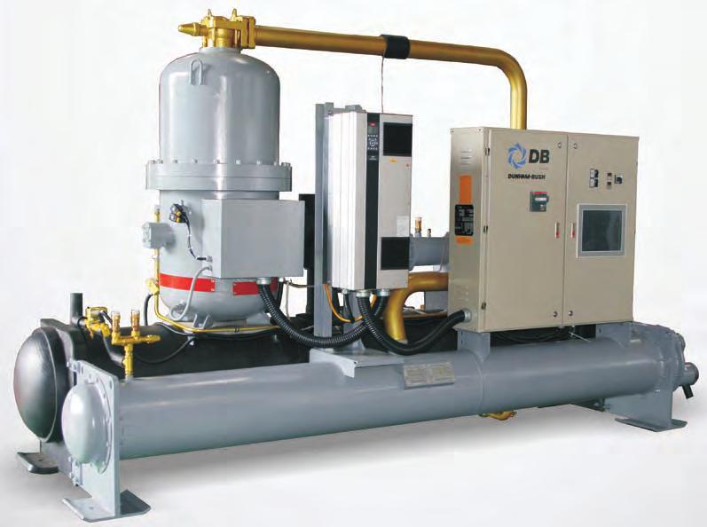
![Performance Ratings D 20 models from 130 to 750 TR [457 to 2638 kw] D Built-in with Variable Frequency Drive (VFD) for compressor, no starter is required Dunham-Bush WCFX-V Chillers are available](/docs-images/89/99641346/images/3-2.jpg "from 130 to 750 TR [457 to 2638 kw]. The vast number of combinations of heat exchangers, compressors and motors make it impractical to publish tabular ratings for each combination.")
3 COMPONENTS Economizer to enhance performance VFD for optimized and improved part load performance Compact, quiet MSC compressor Controller for precise and reliable control Bolted construction for easy knockdown Heat exchangers with cleanable copper tubes and removable water heads for easy serviceability Vessels designed in accordance with ASME code GENERAL CHARACTERISTICS GENERAL Computer Performance Ratings D 20 models from 130 to 750 TR [457 to 2638 kw] D Built-in with Variable Frequency Drive (VFD) for compressor, no starter is required Dunham-Bush WCFX-V Chillers are available from 130 to 750 TR [457 to 2638 kw]. The vast number of combinations of heat exchangers, compressors and motors make it impractical to publish tabular ratings for each combination. A chiller may be custom matched to certain building requirements by your Dunham-Bush Sales Representatives utilizing the WCFX-V Computer Selection Program. Data which can be provided to you will include: D Chiller Capacity D kw Input D Evaporator and Condenser Fluid Temperature D Evaporator and Condenser Pressure Drop D Evaporator and Condenser Tube Water Velocities D Electrical Data D Part-Load Performance D Direct-drive, twin screws compressors driven by VFD offers superior part load energy efficiency D s with twin compressors provide unparallel redundancy and reliability, with enhanced superior part load energy efficiency D Great improvement on Integrated Part Load Value (IPLV), which rated in accordance with AHRI Standards 550/ D Substantially reduced operating sound level, especially at part-load operation; sound level can be reduced up to 12 db(a) for twin compressors models at part load operation D Units are ETL listed for North America and Canada regions Contact our local Dunham-Bush Sales Representative to discuss what Custom Solutions Dunham-Bush can offer to solve your chiller selection questions. -3-

4 GENERAL CHARACTERISTICS Compressors 2 ND OIL SEPARATOR OIL DEFLECTOR CAP 1 ST OIL SEPARATOR MOTOR MALE (DRIVE) ROTOR SUCTION SUCTION CHECK VALVE REPLACEABLE SUCTION FILTER DISCHARGE New generation of Dunham-Bush MSC Vertical Screw Compressors with Unique Patented Screw compressor technology, offers further improved reliability and stability, with lower sound level Optimized oil management with up to 2 integral oil separators. Multi-layered mesh element effectively separates oil from the gas stream No external oil pump required Vertical screw design with unparallel reliability on compressor lubrication; rotor bearings are submerged in oil that guarantees rotor lubrication whenever the compressor is in operation Patented screw profile design which is specially made for R134a application, to assure operation at highest efficiencies Optimized volume ratio, VI port position and geometry for best efficiency Hermetic design eliminates casing leakage, with no requirement for internal parts service, no periodic compressor tear down and overhaul Suction and discharge service valves are provided for the ease of servicing Evaporator / Condenser Shell-and-tube type heat exchanger Flooded type evaporator 2-pass arrangement. 1-pass or 3-pass arrangement available as option Integral finned copper tubes to maximized heat transfer area Cleanable copper tubes for easy serviceability Removable water heads for service Victaulic Groove Water connection comply to ANSI/AWWA C-606 Evaporator comes with 1 [25mm] thick closed cell insulation Standard relief valve(s) 3/4 [19mm] FPT Pressure test up to 220psig for refrigerant side, and 195psig for water side Condenser design capable for full pump down operation Variable Speed Drive (VSD) Regulates motor speed to matched with capacity demand Offers faster response on load changed, and precise capacity control Soft start the compressor to minimized compressor inrush current to virtually, zero inrush current Built-in harmonic filter Built-in Radio Frequency Interference (RFI) filter Maintain displacement power factor at minimum 0.95 at all operating conditions Electronic Expansion Valve (EEV) EEV is used for precise control of liquid refrigerant flow into the evaporator Refrigerant liquid level in evaporator is controlled at precise level for optimum performance EEV with variable speed compressors offer unit operation at most outstanding part-load energy efficiency. This benefits owners by reducing the unit annual operating and lifecycle costs Economizer The economizer circuit consists of plate type heat exchanger, expansion valve and solenoid valve Refrigerant is sub-cooled at economizer before entering the evaporator; the flash refrigerant from economizer is fed into compressor at intermediate pressure The economizer increased cooling capacity by means of the sub-cooling circuit Cooling capacity is increased significantly with marginal increases in kw-input, thus, unit EER is improved Control Panel Electrical enclosure fabricated by heavy gauge sheet steel with powder coated baked finishing Single point power connection for all models Circuit breaker for each compressor motor VFD for compressor motor Solid state motor protector module for compressors Step down transformer for control circuit Main power supply monitoring module. Protection on under or over voltage, phase reversal, phase losses and imbalance Unit mounted Remote/Off/Local (R/O/L) selector switch, an operation and servicing friendly feature Vision 2020i the state-of-art Dunham-Bush proactive advanced controller monitors the unit operation and maintains optimal operation of the unit. Vision 2020i is an intelligent controller that able to operate the unit with optimum efficiency at offdesign conditions. Vision 2020i adapts to any abnormal operating conditions and will execute preventive controls and actions for safety protections - 4 -
5 UNIT FEATURES D D D D D VISION 2020i CONTROLLER D D D D D D Condenser pressure Compressor discharge temperature and superheat Current drawn by each compressor Compressor operating frequency Compressor capacity (percentage of FLA, Full Load Amps) Run hours of each compressor Number of starts of each compressor Electronic Expansion Valve (EEV) Opening Percentage Compressors motor status Oil Level Status, Water Flow Switch Status, Remote Start/Stop Command Status Trend graph of leaving chilled water temperature Capacity Control Vision 2020i, an advance programmable electronic controller designed specifically for the applications and precise control of Dunham-Bush Variable Speed Rotary Screw compressor chillers, WCFX-V. The controller is provided with a set of terminals that connected to various devices such as temperature sensors, pressure and current transducers, solenoid valves, control relays and etc. Three sizes of controller boards are provided to handle different number of input and output requirements: DB3-S small board, DB3-M medium board and DB3-L large board. The unit algorithm program and operating parameters are stored in FLASH-MEMORY that does not require a back-up battery. The program can be loaded through PC or programming key. Vision 2020i controller is equipped with a user friendly DBG5 graphical touch screen color display panel. DBG5 display terminal has dedicated touch keys that provides easy access to the unit operating conditions, control set points, trend graphs and alarm histories. Each unit s controller can be configured and connected to the local DBLAN network that allows multiple units sequencing control without additional hardware. The DBLAN is local area network made up of several chillers controller. Leaving chilled water temperature control is accomplished by entering the water temperature setpoint and placing the controller in automatic control. WCFX-V chillers visualized precise capacity control thanks to the VFD controlled, direct driven compressor. Vision 2020i monitors all control functions and regulates compressor motor speed to match closely to the actual building load requirement. This will put the chiller operation at optimum efficiency at all time, and thus, maximized the energy saving of the chiller plant operation. The compressor ramp (loading) cycle is programmable and may be set for specific building requirements. Remote adjustment of the leaving chilled water setpoint is accomplished either through High Level Interfacing (HLI) via BMS communication, or Low Level Interfacing (LLI) via an external hardwired, 4 to 20mA chilled water reset control signal. Remote reset of compressor current limiting function can be accomplished in a similar fashion System Control The unit may be started or stopped manually, or through the use of an external signal from a Building Automation System. In addition, the controller may be programmed with seven-day operating cycle or other Dunham-Bush control packages may start and stop the system through inter-connecting wiring. Display and User Terminal Vision 2020i controller is designed to work with the DBG5 terminal display, a 7 TFT, 65k colors, LED backlight touch screen graphical display panel. DBG5 terminal display allows carrying out all program operations. The user terminal allows displaying the unit working conditions, compressor run times, alarm history and modifying the parameters. The display also has an automatically self-test of the controller on system startup. Multiple messages will be displayed by automatically scrolling from each message to the next. All of these messages are spelled out in English language on the display terminal. Touch keys on DBG5 graphical display panel allow user to access information and settings, based on security level of the password. For more detail operation of the Display Terminal, please refer to the Unit Operation Manual. Easily accessible measurements include: D Leaving chilled water temperature D Rate of Change for leaving chilled water temperature D Evaporator pressure System Protection The following system protection controls will automatically act to insure system reliability: D Low evaporator pressure D High condenser pressure D Freeze protection D Low suction discharge pressure differential D Low compressor oil level D Compressor run error D Power loss D Chilled water flow loss D Sensor error D Compressor over current D Compressor Anti-recycle D VFD fault The controller can retains up to 99 alarm histories complete with time of failure together with data stamping on critical sensor readings in an alarm condition. This tool will aid service technicians in troubleshooting tasks enabling downtime and nuisance trip-outs to be minimized. -5-
6 UNIT FEATURES Remote Monitoring & Control (Option) Dunham-Bush, the leader of HVAC solution provider understands the arising focus on chiller plant performance and optimization. Several solutions as below are offered to the building owner to achieved optimized chiller plantroom controls, operation and performance. DB-LAN Master Slave Sequencing Control (MSS) In a chiller system with multiple Dunham-Bush chillers, Vision 2020i controller of each chiller can be connected to the DB-LAN network via a communication bus without additional controller, to enable Master-Slave Sequencing Control of this chiller system. MSS will stage in/out chiller in operation to match building required cooling capacity. Chiller Lead-lag, dutystandby and alarm changeover controls are come with MSS, as well as the chilled water pumps control. Each MSS DB-LAN network can be connected up to 8 numbers of chillers. Dunham-Bush Chiller Plant Manager (CPM) DB Chiller Plant Manager (CPM) is a trustworthy and headache-free solution for building owners and users on chiller plant control and automation system. CPM s advanced controllers monitor and control equipments in chiller plant such as chillers, primary and secondary chilled water pumps, condenser water pumps, cooling towers, variable frequency drives (VFD), motorized valves, bypass modulating valves, and etc. Field devices such as flow meters, BTU meters, digital power meters, sensors & transducers can be interfaced with CPM via HLI or LLI. CPM controls chillers, pumps and cooling towers sequencing, as well as lead-lag, dutystandby and alarm changeover operations. NetVisorPRO Monitoring software of CPM system which allows system monitoring, historical trending, and alarm logging to be carry out at a PC terminal. Graphical animations on system operation, temperature and flow rate trend graphs, historical data and alarm history logs, settings changes are all available with NetVisorPRO. Chiller plantroom control and automation by Dunham- Bush CPM provides the owners with a chiller system in stable operation, optimized performance and energy efficiency. Building Management System (BMS) Communication Vision 2020i is able to communicate to BMS through the add-on communication card via various common protocols as: Modbus RTU RS485, ModBus TCPIP BACnet over IP, MS/TP, or PTP LONworks FTT 10 OPTIONS AND ACCESSORIES 1-pass Evaporator and Condenser 1-pass evaporator or condenser is suitable for applications with low temperature different (delta T) or high fluid flow, where the evaporators or condensers are piped in series 3-pass Evaporator and Condenser 3-pass evaporator or condenser is suitable for applications with high delta T and low fluid flow Evaporator and Condenser Flanged Connection Flanged connection is available on request Marine Water Box Marine water box for condenser, for ease of condenser tube cleaning without interfere with field water piping 250 psig Evaporator and Condenser Evaporator and condenser vessels with 250 psig working pressure at water side is available to suite site installation Double Thick Insulation Evaporator with double thick 2 [50mm] closed cell insulation, for extra resistance to condensation Heat Recovery Heat recovery cycle that reclaims waste heat from refrigerant system to produce hot water up to 140 F [60 C]. Two methods of heat recovery are available: shell-and-tube desuperheater or double-bundle condenser Condenser Insulation 1 thick closed cell insulation is provided to discharge piping and double-bundle condenser of heat recovery unit. Hotgas Bypass To maintain unit operation below minimum unloaded capacity Flanged Semi-hermetic Compressor Semi hermetic compressor is available on request Compressor Acoustic Jacket Compressor acoustic jacket is added to further reduce sound level Dual Mode Operation The unit with dual mode operation can deliver chilled fluid temperature down to 18 o F [-7.8 o C] during ice making mode. Units with Dual Mode Operation is used for Ice Thermal Storage System Low Temp. Operation The unit with Low Temp. Operation can deliver chilled fluid temperature down to 18 o F [-7.8 o C] for process cooling application. ASME / PED / CRN / JKKP Compliance Evaporator, condenser and desuperheater with ASME / PED / CRN / JKKP approval is available on request CE Compliance Unit with CE compliance is available on request Electrical & Controls Unit Mounted Main Disconnect Switch Nonfused disconnect switch with external lockable handle is furnished to isolate unit main incoming power supply for servicing Harmonic Filter Additional harmonic filter is added to meet IEEE 519 requirements, which to reduce harmonic distortion to less than 5% of total harmonic distortion (THD) Ground Fault Interrupt (GFI) Provides equipment with ground fault protection Ammeter / Voltmeter Analog ammeter and voltmeter with 3 phase selector switch for indication; located on the control panel - 6 -
7 OPTIONS AND ACCESSORIES Refrigerant Leak Detector A refrigerant detection sensor module is connected to Vision 2020i to monitor refrigerant concentration around the unit. Alarm is triggered and unit is shut down when the refrigerant concentration has exceeded the preset safety limit Chilled Water Reset / Demand Limiting Low level interfacing with Building Automation System (BAS). Chilled Water Reset allows controlled temperature setpoint to be reset by a 4-20mA signal from BAS; while Demand Limiting will limit the maximum current drawn by the compressors by 4-20mA signal from BAS. Chilled Water Pump Control Primary chilled water pump is controlled by chiller s Vision 2020i controller for enhanced safety operation Condenser Water Pump Control Condenser water pump is controlled by chiller for enhanced stable operation Condenser Water Modulating Valve Control A 0-10Vdc control signal is output from Vision 2020i controller to regulates the condenser water modulating valve (field supplied) to bypass portion of condenser water, to allow chiller operation at lower ambient temperature Cooling Tower Fan Staging Control Cooling tower fans staging are controlled by chiller s Vision 2020i controller based on operating condenser pressure. This provides energy saving on cooling tower operation, while maintaining chiller operation at optimum performance Complete Temperature Monitoring Entering evaporator water temperature sensor, leaving and entering condenser water temperature sensors can be included for complete temperature monitoring of the unit IP54 Control Panel IP54 rated control panel can be supplied for harsh working environment System Voltage Readout Voltage of power supply is displayed and logged at Vision 2020i controller GFCI Convenience Outlet (US Region Only) 115Vac convenience outlet with female receptacle BMS Communication Various add-on communication cards provide BMS communication via common protocols: Modbus RTU RS485 / TCPIP, LONworks FTT10, BACnet over IP / MSTP / PTP Factory Supplied, Field Installed Accessories Water Flow Switch Flow switch to be installed at evaporator and condenser outlet piping as safety interlock to evaporator and condenser water flow status. Three options are available: Weather tight flow switch with CE mark; NEMA 3R, and NEMA 4 rated flow switch Rubber-In-Shear Isolators Designed for ease of installation. These one-piece molded rubber isolators are applicable for most installations. Spring Isolators These housed spring assemblies have a neoprene friction pad at the bottom to prevent the passage of noise, and a spring locking levering bolt at the top. Neoprene inserts prevent contact between the steel upper and lower housings. Suitable for more critical application as compared to rubber-in-shear isolator. DB-LAN Master Slave Sequencing Control (MSS) Pre-programmed at factory; field supplied and installed inter-connection wiring between chillers to provide communication bus among chillers controllers to enable Master-Slave Sequencing Control Chiller Plant Manager (CPM) Factory supplied control panel; field supplied and installed interconnection wiring and field devices; for complete chiller plant room automation DB DIRECTOR (For US Region Only) DB-Director control system is offered to US region as an option to Vision 2020i control system. DB-Director is a rugged microprocessor based controller designed for the the HVAC/R applications. DB-Director provides flexibility with setpoints and control options that can be selected prior to commissioning a system or when the unit is live and functioning. Displays, alarms and other interfaces are accomplished in a clear and simple language that informs the user as to the status of the controller. DB-Director is equipped with 128 x 64 pixels monochrome graphics LCD display with 2.8" diagonal viewing area, and 9 dedicated keys that enable user to access information, base on security level of the password. The user terminal is allows displaying and easy access to the unit working conditions, compressor run times, alarm histories and modify the parameters. Multiple messages will be displayed by automatically scrolling from each message to the next. All of these messages are spelled out in English language on the display terminal. The display also has an automatically self-test of the controller on system start-up. For more detail operation of the DB-Director keypad, please refer to the Unit operation Manual. Remote Monitoring For DB-Director DB-Director is equipped with RS485 and Ethernet communication ports as standard. This user friendly design allows Building Management System (BMS) to interface directly with the chiller via either of Modbus RTU, Modbus IP, or BACnet IP communication protocol. LONworks or BACnet MSTP communication protocol can be established with installation of external adapter
8 OPERATING BENEFITS EFFICIENCY & RELIABILITY Compressor Experience More than 45 years of rotary screw experience and dedicated technological advancements. Compressors are CE listed Designed for high reliability with only two rotating parts. No gears to fail Insured continuous oil flow to each compressor through integral high efficiency oil separation for each compressor Chillers use multiple rotary screw compressors for fail-safe reliability and redundancy Refrigerant Compatibility Designed to operate with environmentally safe and economically smart HFC-134a with proven efficiency and reliability Consult factory for use with new HFC refrigerants Energy Efficiency VFD driven compressor provides superior efficiency and sound level at part load Designed to provide the greatest amount of cooling for the least kilowatt input over the entire operating range of your building Delivers outstanding efficiency and total energy savings through the utilization of Variable speed compressor, economizer and controller controlled staging, producing greater capacity with fewer compressors Maximized performance through computer matched components and multiple compressors on a single refrigerant circuit High efficiency oil recovery system guarantees removal of oil carried over in the refrigerant and maintains the heat exchangers at their maximum efficiency at both full and part load operation Installation And Maintenance Ease Side-by-side evaporator/condenser plus snug arrangement of rotary screw compressors result in an extremely compact work envelope Units feature optional split design to allow easy fit through any standard commercial doorway Dramatic payback in reduced maintenance and overhaul costs both in down time and in labor expenditures Ease of troubleshooting through controller retention of monitored functions Evaporators and condensers are designed with removable water heads which can be removed easily without dismantling the chilled water piping connections, for inspection and for mechanical tubes cleaning with brushes or auto-brush. This will enable low tube fouling factor in the evaporator and condenser to be assured, thus maintaining system efficiency Factory Testing Each chiller undergoes the factory testing prior to unit shipment. This assures consistencies of workmanship at highest quality Thus, all units shipped are completely factory tested; charged and adjusted according to the design parameters, for ease of installation and minimal field start-up adjustments Control Flexibility Controller-based with DDC (direct digital control) features precise touch keys control over every aspect of operation with built-in control philosophy that allow extra energy savings on start-up and throughout the life of your equipment Insured uniform compressor loading and optimal energy efficiency through controller controls which utilize pressure transducers to measure evaporator and condenser pressure Lower energy costs resulting from automatic load monitoring and increased accuracy and efficiency in compressor staging Various communication options for remote monitoring of the unit operation Proactive control by controller that anticipates problems and takes corrective action before they occur. Controls will unload compressor(s) if condenser or evaporator pressure approach limits. This will enable unit to stay on the line while warning operator of potential problems Stable and efficient operation with precise chilled water temperature control. Chilled water temperature is controlled at ±0.8 o F [0.5 o C] range for your comfort cooling, with best energy saving - 8 -


9 OPERATING BENEFITS REFRIGERATION CYCLE Dunham-Bush WCFX-V Chillers are designed for efficiency and reliability. The rotary screw compressor is a positive displacement, variable capacity compressor that will allow operation over a wide variety of conditions. Even at high condenser pressure and low capacity, a difficult condition for centrifugal compressors, the rotary screw performs easily. It is impossible for this positive displacement compressor to surge. The refrigerant management system is shown in the refrigerant cycle diagram below. Liquid refrigerant enters the flooded evaporator uniformly where it absorbs heat from water flowing through the evaporator tubes, and vaporized. The vaporized refrigerant is drawn into the compressor suction port where the positive displacement compression begins. This partially compressed refrigerant gaseous is then mixed with additional flash refrigerant from the economizer in the compression camber. The compressed gaseous refrigerant is now discharged into the integral oil separator, to separate lubrication oil from the gaseous refrigerant, and recovers lubrication oil back to the oil sump. The fully compressed and superheated refrigerant is discharged into the condenser, where water in the condenser tubes cools and condenses the refrigerant. Liquid refrigerant leaves the condenser is further subcooled by the economizer. The gaseous refrigerant is drawn out from the economizer and is injected into compressor through the vapor injection port. The remaining liquid refrigerant shall passes through the Electronic Expansion Valve (EEV) which reduces refrigerant pressure to evaporator levels where it is then distributed evenly into the evaporator. This delivers outstanding efficiency and total energy savings through the utilization of economizer cycle. Unit EER is improved with economizer cycle. PART LOAD PERFORMANCE Through the use of economizer and multiple compressors, Dunham-Bush WCFX-V Chillers, some of the best part-load performance characteristics in the industry when measured in accordance with AHRI Standard 550/ In most cases, actual building system loads are significantly less than full load design conditions, therefore chillers operate at part load most of the time. Dunham-Bush WCFX-V Chillers combine the efficient operation of Variable Frequency Drive (VFD), multiple rotary screw compressors with economizer and controller control to yield the best total energy efficiency and significant operating savings under any load. When specifying air conditioning equipment, it is important to consider the system load characteristics for the building application. In a typical city, the air conditioning load will vary according to changes in the ambient temperature. Weather data compiled over many years will predict the number of hours that equipment will operate at various load percentages. The Air Conditioning and Refrigeration Institute (AHRI) has established a system, in AHRI Standard 550/ , for measuring total chiller performance over full and part-load conditions. It defines the Integrated Part- Load Value (IPLV) as an excellent method of comparing diverse types of equipment on an equal basis. The IPLV is a single number estimate of a chiller's power use weighted for the number of hours the unit might spend at each part-load point. IPLV's are based on AHRI Standard Rating Conditions. The formula for calculating an IPLV is: IPLV = A B C D where: A= kw/ton at 100% load point B= kw/ton at 75% load point C= kw/ton at 50% load point D= kw/ton at 25% load point - 9 -
10 PHYSICAL SPECIFICATIONS WCFX-V 19S 20S 23S 24S 27S 30S 36S 38T 40T 41S Nominal Capacity TR [kw] [468.8] [578.5] [656.3] [711.8] [776.6] [875.7] [1030.1] [954.2] [1164.5] [1170.5] Nominal Power Input kw Energy efficiency kw/tr COP Min. % Unit Capacity 20% 20% 20% 20% 20% 20% 20% 10% 10% 20% Power Supply V/PH/Hz /3/50, 380/3/60, 460/3/60, 575/3/60 Compressor (Qty) 1220(1) 1222(1) 1222(1) 1227(1) 1227(1) 1230(1) 2233(1) 1220(2) 1222(2) 2236 (1) Evaporator FAR EAR JAR JBR 6DR 6ER 7CR 6CR 8BR 7BR Water Connection Inch Design Press. Water Side psig [kpa] 150[1034] Flow rate USgpm [m 3 /h] 319.2[72.5] 393.8[89.4] 446.9[101.4] 484.7[110.0] 528.8[120.0] 596.1[135.3] 701.3[159.1] 649.5[147.4] 792.8[180.0] 796.9[180.9] Pressure Drop ft wg [kpa] 4.4 [13.1] 9.5 [28.3] 9.7 [29.0] 9.9 [29.6] 8.5 [25.5] 9.5 [28.3] 10.1 [30.3] 11.1 [33.1] 10.1 [30.3] 10.4 [31.0] Condenser D2R 5BR 5BR 5CR 6CR 1KR RAR K5R M3R M1R Water Connection Inch Design Press. Water Side psig [kpa] 150[1034] Flow rate USgpm [m 3 /h] 402.3[91.3] 495.6[112.5] 560.7[127.3] 609.5[138.4] 663.2[150.5] 750.3[170.3] 879.0[199.5] 814.1[184.8] 994.8[225.8] 998.3[226.6] Pressure Drop ft wg [kpa] 7.8 [23.4] 10.6 [31.7] 12.9 [38.6] 11.5 [34.5] 12.0 [35.9] 11.5 [34.5] 12.5 [37.2] 15.2 [45.5] 14.1 [42.1] 12.0 [35.9] Unit Length Inch [mm] 132 3/16 [3360] 164 3/16 [4170] 164 3/16 [4170] 164 3/16 [4170] General Unit Width Inch [mm] 70 [1780] 70 [1780] 70 [1780] 70 [1780] 70 [1780] 70 [1780] 70 [1780] 75 [1910] 80 [2030] 70 [1780] Unit Height Inch [mm] 79 [2010] 79 [2010] 79 [2010] 79 [2010] 81 [2060] 79 15/16 [2030] 92 1/8 [2340] 84 [2130] 87 15/16 [2230] 94 1/8 [2390] Unit Shipping Weight lbs [kg] 7532 [3416] 7830 [3551] 8367 [3795] 8692 [3942] 9321 [4227] [4615] [5863] [6335] [7266] [6300] 164 3/16 [4170] 164 3/16 [4170] 174 7/16 [4430] 196 3/4 [5000] 196 3/4 [5000] 174 7/16 [4430] Unit Operating Weight lbs [kg] 8258 [3745] 8666 [3930] 9262 [4200] 9661 [4381] [4711] [5156] [6570] [6981] [8090] [7099] R134a Charge (Approx)lbs [kg] 419 [190] 529 [240] 558 [253] 584 [265] 705 [320] 750 [340] 981 [445] 882 [400] 1014 [460] 1102 [500] WCFX-V 46S 46T 50T 54T 57T 60T 73T 75T 81T 87T 90T Nominal Capacity TR [kw] [1324.5] [1321.3] [1442.7] [1565.1] [1670.6] [1774.7] [2051.8] [2191.8] [2344.1] [2492.1] Nominal Power Input kw Energy efficiency kw/tr COP Min. % Unit Capacity 20% 10% 10% 10% 10% 10% 10% 10% 10% 10% 10% Power Supply V/PH/Hz /3/50, 380/3/60, 460/3/60, 575/3/60 (Qty) 2246 (1) 1222 (2) 1222 (1) 1227 (1) Compressor 1227 (2) 1227 (1) 1230 (1) Evaporator 1230 (2) 2233 (2) 2233 (1) 2236 (1) 2236 (2) 2236(1) 2246(1) 8DR 8DR KBR YAR YBR YCR MAR MBR NAR PAR PAR [2633.5] Water Connection Inch Design Press. Water Side psig [kpa] 150[1034] Flow rate USgpm [m 3 /h] [204.7] [204.2] [222.9] [241.8] [258.2] [274.3] [317.2] [338.7] [362.3] [385.2] [406.8] Pressure Drop ft wg [kpa] 13.4 [40.0] 11.3 [33.8] 10.8 [32.4] 11.1 [33.1] 11.3 [33.8] 11.8 [35.2] 12.2 [36.5] 12.7 [37.9] 11.3 [33.8] 13.6 [40.7] 15.0 [44.8] Condenser M5R M5R T5R YAR YBR YCR JAR JBR KAR 7CR 8AR Water Connection Inch Design Press. Water Side psig [kpa] 150[1034] Flow Rate USgpm [m 3 /h] [255.9] [255.6] [280.0] [302.7] [323.2] [343.6] [398.0] [424.9] [453.9] [481.5] [510.2] Pressure Drop ft wg [kpa] 13.1 [39.3] 12.0 [35.9] 12.7 [37.9] 12.2 [36.5] 12.7 [37.9] 12.9 [38.6] 14.5 [43.4] 13.4 [40.0] 12.5 [37.2] 15.2 [45.5] 15.5 [46.2] General Unit Length Inch [mm] 174 7/16 [4430] 196 3/4 [5000] 196 3/4 [5000] 196 3/4 [5000] 196 3/4 [5000] 196 3/4 [5000] /16 [5250] /16 [5250] /16 [5250] 213 3/4 [5430] 213 3/4 5430] Unit Width Inch [mm] 75 3/16 [1910] 80 [2030] 80 [2030] 80 [2030] 80 [2030] 80 [2030] 88 3/16 [2240] 88 3/16 [2240] 88 3/16 [2240] 90 3/16 [2290] 90 3/16 [2290] Unit Height Inch [mm] 96 7/8 [2460] 88 [2240] 92 [2340] 97 [2460] 97 [2460] 97 [2460] 99 3/16 [2520] 99 3/16 [2520] 96 1/16 [2440] 98 13/16 [2510] 98 13/16 [2510] Unit Shipping Weight lbs [kg] [6745] [7571] [7971] [8676] [8908] [9160] [10914] [11160] [12390] [13268] [13727] Unit Operating Weight lbs [kg] [7648] [8483] [8948] [9780] [10052] [10351] [12221] [12553] [13966] [15067] [15594] R134a Charge (Approx)lbs [kg] 1113 [505] 1113 [505] 1312 [595] 1356 [615] 1422 [645] 1477 [670] 1455 [660] 1543 [700] 1808 [820] 2701 [1225] 2701 [1225] Notes: 1. The above data are for Superior models with 2-pass evaporator and condenser which rated in accordance with AHRI Standard 550/590 (I-P)-2015 at standard conditions. The standard rating conditions are as below: Chilled Water Inlet/Outlet Temperature 54/44 F [12.2/6.7 C]; Cooling Water Inlet/Outlet Temperature 85/94.3 F [29.4/34.6 C]; evaporator fouling factor hr.ft². F/Btu [0.018 m² K/kW]; condenser fouling factor hr.ft². F/Btu [0.044 m 2 K/kW]. 2. To consult nearest Dunham-Bush sales office for computer selections other than above operating conditions 2246 (2)
11 SOUND PRESSURE DATA WCFX-V Octave Band (Hz) Total db (A) 19S S S S S S S T T S S WCFX-V Octave Band (Hz) Total db (A) 46T T T T T T T T T T Note: Sound Pressure Level 3.3ft [1m] (free field) ± 2dBA. ELECTRICAL DATA 50/60Hz WCFX-V 60Hz Power Supply 380Vac ± 10% -3Ph-50Hz 400Vac ± 10% -3Ph-50Hz Compressor Unit Compressor Unit Compressor RLA MCA MFS RLA LRA RLA MCA MFS RLA LRA 19S 1220 (1) S 1222 (1) S 1222 (1) S 1227 (1) S 1227 (1) S 1230 (1) S 2233 (1) T 1220 (2) T 1222 (2) S 2236 (1) S 2246 (1) T 1222 (2) T 1222 (1) (1) T 1227(2) T 1227 (1) (1) T 1230 (2) T 2233 (2) T 2233 (1) (1) T 2236 (2) T 2236 (1) (1) T 2246 (2) WCFX-V Power Supply 460Vac ± 10% -3Ph-60Hz 575Vac ± 10% -3Ph-60Hz Compressor Unit Compressor Unit Compressor RLA MCA MFS RLA LRA RLA MCA MFS RLA LRA 19S 1220 (1) S 1222 (1) S 1222 (1) S 1227 (1) S 1227 (1) S 1230 (1) S 2233 (1) T 1220 (2) T 1222 (2) S 2236 (1) S 2246 (1) T 1222 (2) T 1222 (1) (1) T 1227(2) T 1227 (1) (1) T 1230 (2) T 2233 (2) T 2233 (1) (1) T 2236 (2) T 2236 (1) (1) T 2246 (2) Notes: 1.) RLA Rated Load Amps MCA Minimum Circuit Amps MFS Maximum Fuse Size LRA Locked Rotor Amps 2.) The above data are are for Superior models, which rated in accordance with AHRI Standard 550/590 (I-P)-2015 at standard conditions
12 DIMENSIONAL DATA WCFX-V 19S WCFX-E Evap. Cond. Water Connector Dimensions- inches [mm] inches Length Width Height A B C D E F YØ ZØ 19S FAR D2R 132 3/16 [3360] 70 [1780] 79 [2010] 5 5/8 [143] 29 3/4 [756] 6 7/8 [175] 21 5/16 [542] 2 1/2 [64] 15 7/8 [403] 6 8 WCFX-V 20S, 23S, 24S, 27S, 30S, 36S, 41S, 46S WCFX-E Evap. Cond. Water Connector Dimensions- inches [mm] inches Length Width Height A B C D E F YØ ZØ 20S EAR 5BR 164 5/16 [4170] 70 [1780] 79 [2010] 5 5/8 [143] 28 9/16 [725] 5 5/8 [143] 22 5/16 [567] 1 1/4 [31] 15 7/8 [403] S JAR 5BR 164 3/16 [4170] 70 [1780] 79 [2010] 5 5/8 [143] 29 3/4 [756] 6 7/8 [175] 21 5/16 [542] 2 1/2 [64] 15 7/8 [403] S JBR 5CR 164 3/16 [4170] 70 [1780] 79 [2010] 5 5/8 [143] 29 3/4 [756] 6 7/8 [175] 21 5/16 [542] 2 1/2 [64] 15 7/8 [403] S 6DR 6CR 164 3/16 [4170] 70 [1780] 81 [2060] 5 5/8 [143] 30 13/16 [782] 6 7/8 [175] 22 5/16 [567] 3 1/2 [89] 15 7/8 [403] S 6ER 1KR 164 3/16 [4170] 70 [1780] 79 15/16 [2030] 6 1/8 [155] 31 3/4 [807] 6 7/8 [175] 22 5/16 [567] 2 1/8 [54] 15 7/8 [403] S 7CR RAR 174 3/16 [4430] 70 [1780] 92 1/8 [2340] 6 7/8 [175] 35 1/4 [895] 8 1/8 [207] 24 5/16 [618] 2 [51] 15 7/8 [403] S 7BR M1R 174 3/16 [4430] 70 [1780] 94 1/8 [2390] 6 7/8 [175] 36 1/4 [920] 7 3/8 [187] 24 5/16 [618] 1 [25] 15 7/8 [403] S 8DR M5R 174 3/16 [4430] 75 [1910] 96 7/8 [2460] 6 7/8 [175] 37 5/16 [948] 8 1/8 [207] 26 5/16 [669] 2 [51] 20 [508] Notes: 1.) Above drawings and dimensions are for Superior models with vessels construction based on flat head and comply with PED/ JKKP/ Chinese Machinery codes. 2.) Unit layout shown are for reference only. Some orientations may vary. 3.) Consult factory for models with vessels with ASME/ other approvals
13 DIMENSIONAL DATA WCFX-V 38T, 40T, 46T, 50T, 54T, 57T, 60T WCFX-E Evap. Cond. Water Connector Dimensions- inches [mm] inches Length Width Height A B C D E F YØ ZØ 38T 6CR K5R 196 3/4 [5000] 75 [1910] 84 [2130] 6 1/16 [155] 31 3/4 [807] 6 7/8 [175] 24 5/16 [618] 2 3/16 [55] 17 1/2 [444] T 8BR M3R 196 3/4 [5000] 80 [2030] 87 15/16 [2230] 6 7/8 [175] 35 13/16 [909] 8 1/8 [207] 26 5/16 [669] 2 [51] 20 [508] T 8DR M5R 196 3/4 [5000] 80 [2030] 88 [2240] 6 7/8 [175] 35 13/16 [909] 8 1/8 [207] 26 5/16 [669] 2 [51] 20 [508] T KBR T5R 196 3/4 [5000] 80 [2030] 92 [2340] 6 7/8 [175] 36 3/4 [934] 8 1/8 [207] 27 5/16 [694] 3 [76] 20 [508] T YAR YAR 196 3/4 [5000] 80 [2030] 97 [2460] 7 3/8 [187] 39 11/16 [1008] 8 7/8 [226] 28 5/16 [719] 3 7/8 [99] 20 [508] T YBR YBR 196 3/4 [5000] 80 [2030] 97 [2460] 7 3/8 [187] 39 11/16 [1008] 8 7/8 [226] 28 5/16 [719] 3 7/8 [99] 20 [508] T YCR YCR 196 3/4 [5000] 80 [2030] 97 [2460] 7 3/8 [187] 39 11/16 [1008] 8 7/8 [226] 28 5/16 [719] 3 7/8 [99] 20 [508] WCFX-V 73T, 75T, 81T, 87T, 90T Y( Y( WCFX-E Evap. Cond. Water Connector Dimensions- inches [mm] inches Length Width Height A B C D E F YØ ZØ 73T MAR JAR /16 [5250] 88 3/16 [2240] 99 3/16 [2520] 8 [203] 40 13/16 [1036] 10 3/16 [258] 29 5/16 [744] 3 1/4 [82] 24 1/2 [622] T MBR JBR /16 [5250] 88 3/16 [2240] 99 3/16 [2520] 8 [203] 40 13/16 [1036] 10 3/16 [258] 29 5/16 [744] 3 1/4 [82] 24 1/2 [622] T NAR KAR /16 [5250] 88 3/16 [2240] 96 1/16 [2440] 8 1/8 [207] 48 [1219] 10 1/8 [257] 30 1/4 [769] 4 1/4 [108] 24 1/2 [622] T PAR 7CR 213 3/4 [5430] 90 3/16 [2290] 98 13/16 [2510] 9 3/4 [248] 49 [1144] 10 3/16 [259] 32 5/16 [821] 5 1/4 [133] 25 1/2 [648] T PAR 8AR 213 3/4 [5430] 90 3/16 [2290] 98 13/16 [2510] 9 3/4 [248] 47 3/4 [1213] 10 3/16 [259] 32 5/16 [821] 3 3/8 [86] 25 1/2 [648] Notes: 1.) Above drawings and dimensions are for Superior models with vessels construction based on flat head and comply with PED/ JKKP/ Chinese Machinery codes. 2.) Unit layout shown are for reference only. Some orientations may vary. 3.) Consult factory for models with vessels with ASME/ other approvals
14 FLOOR LOADING DIAGRAM WCFX-V 19S, 20S, 23S, 24S, 27S, 30S, 36S, WCFX-V 38T, 40T, 41T, 46T, 50T, 54T, 57T, 60T, 41S, 46S 73T, 75T, 81T, 87T, 90T 1.) Point Load Location - Inches[mm] WCFX-V L1 L2 L3 L4 L5 W 19S 15 [381] 33 3/16 [843] 33 3/16 [843] 33 3/16 [843] 15 7/16 [391] 11/16 [17] 20S 20 [508] 40 11/16 [1033] 40 11/16 [1033] 40 11/16 [1033] 20 [508] 11/16 [17] 23S 20 [508] 40 11/16 [1033] 40 11/16 [1033] 40 11/16 [1033] 20 [508] 11/16 [17] 24S 20 [508] 40 11/16 [1033] 40 11/16 [1033] 40 11/16 [1033] 20 [508] 11/16 [17] 27S 20 [508] 40 11/16 [1033] 40 11/16 [1033] 40 11/16 [1033] 20 [508] 11/16 [17] 30S 20 [508] 40 11/16 [1033] 40 11/16 [1033] 40 11/16 [1033] 20 [508] 11/16 [17] 36S 20 [508] 40 11/16 [1033] 40 11/16 [1033] 50 11/16 [1287] 20 [508] 11/16 [17] 38T 15 [381] 60 [1524] 60 [1524] 45 [1143] 15 [381] 1 1/2 [38] 40T 15 [381] 60 [1524] 60 [1524] 45 [1143] 15 [381] 1 1/2 [38] 41S 20 [508] 40 11/16 [1033] 40 11/16 [1033] 50 11/16 [1287] 20 [508] 11/16 [17] 46S 20 [508] 40 11/16 [1033] 40 11/16 [1033] 50 11/16 [1287] 20 [508] 11/16 [17] 46T 15 [381] 55 [1397] 55 [1397] 55 [1397] 15 [381] 1 1/2 [38] 50T 15 [381] 55 [1397] 55 [1397] 55 [1397] 15 [381] 1 1/2 [38] 54T 15 [381] 55 [1397] 55 [1397] 55 [1397] 15 [381] 1 1/2 [38] 57T 15 [381] 55 [1397] 55 [1397] 55 [1397] 15 [381] 1 1/2 [38] 60T 15 [381] 60 [1524] 60 [1524] 45 [1143] 15 [381] 1 1/2 [38] 73T 15 [381] 53 11/16 [1363] 60 11/16 [1541] 60 11/16 [1541] 15 [381] 1 1/2 [38] 75T 15 [381] 53 11/16 [1363] 60 11/16 [1541] 60 11/16 [1541] 15 [381] 1 1/2 [38] 81T 15 [381] 53 11/16 [1363] 60 11/16 [1541] 60 11/16 [1541] 15 [381] 1 1/2 [38] 87T 15 [381] 60 11/16 [1541] 60 11/16 [1541] 60 11/16 [1541] 15 [381] 1 1/2 [38] 90T 15 [381] 60 11/16 [1541] 60 11/16 [1541] 60 11/16 [1541] 15 [381] 1 1/2 [38] 2.) Point Load Data - Lbs [kg] WCFX-V P1 P2 P3 P4 P5 P6 P7 P8 Operating Weight 19S 1118 [507] 1391 [631] 954 [433] 1258 [571] 790 [358] 1126 [511] 626 [284] 993 [451] 8256 [3744] 20S 1109 [503] 1459 [662] 965 [438] 1335 [605] 822 [373] 1210 [549] 678 [308] 1086 [493] 8665 [3930] 23S 1165 [529] 1564 [709] 1019 [462] 1434 [650] 873 [396] 1304 [591] 727 [330] 1173 [532] 9260 [4199] 24S 1236 [561] 1631 [740] 1074 [487] 1492 [676] 911 [413] 1353 [613] 749 [340] 1214 [550] 9659 [4380] 27S 1300 [590] 1765 [800] 1135 [515] 1618 [734] 970 [440] 1471 [667] 804 [365] 1324 [600] [4710] 30S 1422 [645] 1947 [883] 1234 [560] 1783 [809] 1046 [474] 1619 [734] 858 [389] 1456 [660] [5154] 36S 1543 [700] 2320 [1052] 1480 [671] 2222 [1008] 1417 [643] 2124 [963] 1354 [614] 2026 [919] [6569] 38T 1958 [888] 2157 [978] 1802 [817] 2134 [968] 1646 [747] 2112 [958] 1490 [676] 2090 [948] [6979] 40T 2170 [984] 2536 [1150] 2014 [914] 2527 [1146] 1859 [843] 2517 [1142] 1703 [772] 2508 [1137] [8088] 41S 1626 [738] 2550 [1156] 1558 [706] 2443 [1108] 1489 [675] 2336 [1059] 1420 [644] 2229 [1011] [7098] 46S 1915 [868] 2590 [1174] 1830 [830] 2482 [1126] 1744 [791] 2375 [1077] 1659 [752] 2267 [1028] [7647] 46T 2236 [1014] 2618 [1187] 2090 [948] 2644 [1199] 1945 [882] 2671 [1211] 1799 [816] 2698 [1224] [8481] 50T 2203 [999] 2710 [1229] 2154 [977] 2771 [1257] 2105 [955] 2832 [1284] 2056 [933] 2893 [1312] [8946] 54T 2353 [1067] 2981 [1352] 2316 [1050] 3055 [1386] 2280 [1034] 3129 [1419] 2243 [1017] 3204 [1453] [9778] 57T 2444 [1108] 3052 [1384] 2399 [1088] 3126 [1418] 2355 [1068] 3200 [1451] 2310 [1048] 3274 [1485] [10050] 60T 2511 [1139] 3124 [1417] 2478 [1124] 3203 [1453] 2446 [1109] 3283 [1489] 2413 [1094] 3362 [1525] [10349] 73T 3317 [1505] 3547 [1609] 3134 [1421] 3644 [1653] 2951 [1338] 3742 [1697] 2768 [1255] 3839 [1741] [12219] 75T 3396 [1540] 3651 [1656] 3209 [1455] 3752 [1702] 3022 [1371] 3853 [1747] 2835 [1286] 3954 [1793] [12550] 81T 3650 [1655] 4099 [1859] 3483 [1580] 4232 [1919] 3316 [1504] 4364 [1979] 3149 [1428] 4496 [2039] [13963] 87T 3715 [1685] 4471 [2028] 3646 [1653] 4619 [2095] 3576 [1622] 4767 [2162] 3506 [1590] 4915 [2229] [15064] 90T 3809 [1727] 4642 [2105] 3746 [1699] 4800 [2177] 3684 [1671] 4958 [2249] 3622 [1642] 5116 [2320] [15591] Note: Floor loading diagram (Figure 3.6). Unit must be lowered onto mounting springs in a level fashion or spring damage may occur
15 CLEARANCE FOR SERVICE Sufficient clearance around the unit is required to ensure proper unit operation, and as space for service and maintenance works. Below clearance requirements are general guideline, where local health and safety regulations, and other practical considerations shall be taken into account. Front 45 [1143mm] Rear 18 [457mm] Top 18 [457mm] End Tube length at one side for tube servicing; 36 [914mm] at the other end. Unit Clearance 1.) Single Compressor Unit 2.) Two Compressors Unit
16 TYPICAL WIRING SCHEMATIC Two Compressors Unit (Vision 2020i)
17 APPLICATION DATA EVAPORATOR FLUID CIRCUIT The evaporator fluid circuit requires a minimum system fluid volume of 3 US gallons per Ton [3.3 liters/ cooling kw] for stable operation. The minimum system fluid volume may increasing up to 10 US gallons per Ton [11 liters/ cooling kw] for process cooling, low load applications with small temperature range and/or vastly fluctuating load conditions. Variable Evaporator Flow Dunham-Bush chillers are capable for variable evaporator flow system. The chiller may operate to maintain constant leaving fluid temperature with evaporator flow rate changes, with below conditions fulfilled. Evaporator fluid flow rate is within minimum and maximum flow rate of the unit at all time during the operation Rate of flow changed shall not exceeded 10% per minute Failure to comply with the above conditions will cause problem to the chiller operation and may cause the chiller to shutdown. Operating Limits - Leaving Evaporator Fluid Temperature Leaving Fluid Temperature Minimum Maximum Standard 40 o F [4.5 o C] 55 o F [12.8 o C] Dual Mode / Low Temp. Operation 18 o F [-7.8 o C] 55 o F [12.8 o C] Performance Correction- Evaporator Fouling Factor Fouling Factor hr.ft². F/BTU m². C/kW Capacity Correction Factor kw-input Correction Factor CONDENSER FLUID CIRCUIT The unit shall works with constant condenser flow, variable condenser flow is not recommended. Variable condenser flow will keep condenser pressure high at the chiller, and thus, decreases chiller s efficiency and increase power consumption of the system. In addition, variable condenser flow increases rate of fouling of condenser, which will de-rating chiller performance and increases unit maintenance cost. The unit can be operated with condenser inlet water temperature above 55 F up to 105 F. If the unit is required to operates with condenser inlet water temperature lower than 55 F, a bypass control at condenser water loop is recommended to maintain condenser inlet water temperature is always higher than 55 F. Performance Correction - Condenser Fouling Factor hr.ft². F/BTU Fouling Factor m². C/kW Capacity Correction Factor kw-input Correction Factor GLYCOL FREEZE PROTECTION If the chiller or fluid piping may be exposed to temperatures below freezing, glycol protection is recommended if the water is not drained. The recommended protection is 10 F [5.6 C] below the minimum ambient temperature in the equipment room and around piping. Use only glycol solutions approved for heat exchanger duty. DO NOT use automotive antifreezing. If the equipment is being used for applications below 38 F [3.3 C], glycol should be used to prevent freeze damage. The freeze protection level should be 15 F [8.3 C] lower than the leaving brine temperature. Table 1 and 2 are to be used to calculate performance and power input with the addition of glycol. Table 1 : Ethylene Glycol % E. G. By Weight Freeze Point F C C1 Capacity Factor K1 kw-input Factor G1 Flow Factor P1 P.D. Factor Table 2 : Propylene Glycol % P. G. By Weight Freeze Point F C C2 Capacity Factor K2 kw-input Factor G2 Flow Factor P2 P.D. Factor Note: P.D. Pressure drop vessels across HEAT RECOVERY The Dunham-Bush WCFX-V Chiller can significantly reduce building operating costs when the heat recovery option is selected. Any building which requires simultaneous heating and cooling may be an excellent candidate for this system. Hotter Hot Water Most centrifugal water chillers are limited in producing leaving condenser water temperatures to 105 F[40 C] or below. Dunham-Bush WCFX-V Chillers are able to provide leaving hot water temperatures up 140 F[60 C] allowing for the installation of smaller heating coils at a lower first cost than systems utilizing centrifugal water chillers. The warmer supply air temperatures available will also improve tenant comfort. Lower Energy Consumption The efficient unloading characteristics of the Dunham- Bush WCFX-V Chiller compressor make it ideal for heat recovery duty. Heat recovery chillers must be selected to operate at many operating conditions, not just full load heating and full load cooling duties. Heat recovery chillers spend the majority of their time at lower loads, conditions at which centrifugal chillers must often be operating with energy inefficient hot gas bypass
18 APPLICATION DATA Greater Design Flexibility The heat recovery Dunham-Bush WCFX-V Chiller, on the other hand, utilizes Variable Frequency Driven (VFD), positive displacement compressor which will not surge. This chiller is capable of unloading its compressors to their minimum capacity at all head conditions, both cooling and heat recovery, for greater design flexibility. In order to maximize the user s flexibility on design and operation, Dunham-Bush chillers offer two heat recovery designs. Desuperheater: A shell-and-tube desuperheater is installed at chiller to reclaim waste heat from superheated refrigerant produced by the vapor compression cycle. Double-Bundle Condenser: Double-bundle condenser with two sets of water connectors allow connections to hot water loop and cooling tower water loop simultaneously. Double-Bundle condenser is rated at 300 psig [20.7Bar] working pressure on refrigerant side, and is pressure test up to 330 psig [22.8 Bar] in the factory. This design reclaims waste heats generated by vapor compression cycle, and full heat reclaim can be done with this design. Condenser thermal insulation is can be included to provide heat insulation on double-bundle condenser and discharge piping. The 1 thick closed cell insulation will reduce heat losses during heat recovery operation, and prevent unpleasant human contact with hot surface. To further improve the operational flexibility, for units with full heat recovery design, priority on controlled temperature can be selected through a digital input signal. When Heating Mode contact is closed, controlled temperature will switch from leaving evaporator water temperature to leaving condenser water temperature; thus, the unit is now operated as a heat pump. This control function is available when Condenser Water Pump Control & Complete Temperature Monitoring options are included together with double-bundle condenser option. CONDENSER PRESSURE CONTROL Cooling tower control is increasingly becoming an overlooked subject, and it causes problems. The following is a general recommendation that is applicable to all standard packaged chillers. Most chiller manufacturers recommend that condenser water be controlled so that its temperature never goes below 55 F [12.8 C] (even when the machine is off) and that its rate of change is not rapid. Rapid can be defined as not exceeding 2 F [1.1 C] per minute. This is necessary because a chiller operates in a dynamic environment and is designed to maintain a precise leaving chilled water temperature under varying entering chilled water conditions. The additional dynamic of rapidly varying condenser water temperature subjects the machine to fluctuating pressure on differentials across the evaporator and condenser. This varies the refrigerant flow and, therefore, the capacity. If this occurs faster than the machine can accommodate it, the condenser pressure or evaporator pressure will soon exceed their safety setpoints and the machine will shut down. The necessary control can sometimes be attained via fan cycling if the tower is rated at the same capacity as the chiller s heat rejection. On multiple chiller jobs, a single tower is oversized relative to the chiller. On other jobs the tower/chiller might be oversized to the design load and the chiller and tower frequently cycle under light load. Under these conditions, fan cycling might result in very rapid temperature swings, which creates a dynamic situation to condenser, that potentially cause unstable operation. Thus, in this case, either variable speed fans or modulating valve control should be used to regain control of the condenser water. Either type of control provides precise modulating control of the condenser water rather than on-off step control. The control can be initiated either by a condenser water temperature sensor/controller or, even better, by direct control from the chiller's controller based upon the chiller's condenser pressure. It is further recommended that the condenser water pump be cycled by the chiller. This is to eliminate potentially very cold water from going through the condenser while the chiller is shut down. At the same time it is probable that relatively warmer chilled water is in the evaporator (an inversion). Refrigerant tends to migrate if there is a difference in pressures within the components of the chiller. It will seek the lowest pressure area of the packaged chiller which, in this case, would be the condenser. Starting of a chiller where the refrigerant has migrated to the condenser is not desirable. The presence of highly subcooled liquid refrigerant in the condenser will cause low suction pressures and possibly liquid slugging of the compressor. If the condenser water pump is off until prior to the chiller starts, the water in the condenser is at the chiller room ambient, which is usually much closer to the evaporator water temperature. Further to condenser pump control, a 0-10 Vdc analog signal can be output from the chiller s controller to bypass some of the condenser water flow to maintain chiller s condenser pressure. Cooling tower fans control is also available to achieve better system efficiency. Thus, even though there has been a trend toward fan cycling control of cooling towers, it is not a device that is suitable to every installation. We recommend that the designer carefully evaluate the system to determine if a more precise method of control is indicated. If there is any doubt, the more precise control is required. Dunham-Bush WCFX-V Chillers have as standard a control feature called EPCAS (Evaporator Pressure Control at Start) which will allow for an inverted start. This occurs when the chilled water loop in a building is at a higher temperature than the condenser/tower loop. This occurs in many buildings after a weekend shut down. The chilled water loop can be as high as 90 F and the condenser/tower loop as low as 60 F. With the EPCAS feature, the valve feeding the evaporator will be throttled to create a pressure differential to help load the compressor
19 APPLICATION DATA ICE THERMAL STORAGE SYSTEM (ITES) The globe is progressively marching towards a serious electric energy crisis. The HVAC/R industry is shifting to operate with more efficient machines, as well as alternate system designs and solutions. Dunham-Bush, as a leader of HVAC/R solutions provider, we provide packaged solution for ITES, which include, equipments selections, chillers, Ice Cels and CPM for ITES system controls. Dunham-Bush WCFX-V Chillers, with positive displacement rotary screw compressor can easily cool low temperature glycol down to 20 F [-6.7 o C] to charge the ice storage tanks. The same chiller can also produce warmer supply fluid temperature, 40 to 45 o F [4.4 to 7.2 o C], for those building systems designed for only peak shaving. Dunham-Bush is the only HVAC/R manufacturer who can provide complete ITES packaged solution, with own products for chillers, ice storage tanks and plant room control system, with following benefits. Demand Charge: ITES allows some of the peak demand to be shifted to low-demand nighttime periods, thus reducing demand charges for the entire year. Energy Cost: ITES, by operating chillers at night, will fully utilize incentive on electricity night tariff, which is much lower compare to day tariff Rebates: ITES usually qualifies for rebates offered by electric utilities or governments for equipment that shift peak loads to off-peak hours Colder Air Temperature: ITES can produce chilled liquid at supply temperature of 38 F [3.3 C] or even lower without scarifying system s efficiencies. This realizes energy saving on chilled water pumping system, AHUs and FCUs. Colder supply air distribution lowers room humidity, and thus, comfort cooling can be achieved with higher room temperature. This reduce air conditioning load required, and therefore, reduces the installation cost and system operating cost. Standby Cooling Capacity: Energy stored in ITES can be utilized to cater peak or unexpected loads which exceeded total cooling capacity available from the installed chillers. This is savior to the regions which having difficulties on power generation plants expansion, where with ITES, will significantly reduced total demand of the buildings. GUIDE SPECIFICATIONS SCOPE Supply and commissioning of complete factory assembled water cooled rotary screw chiller(s). The rotary screw chiller(s) shall contain rotary screw compressor(s), evaporator, condenser, interconnecting refrigerant piping, electronic expansion valve, control panel, Variable Frequency Drive (s), chilled liquid connections, condenser water connections. The control panel shall be fully wired by the manufacturer connecting & interlocking, controller, Variable Frequency Drive, electrical protection devices with electrical power and control connections. Packaged chiller shall be factory assembled, charged with a full operating refrigerant and oil charge and tested. The refrigerant type shall be R134a, and shall not have phasing out schedule. Capacity of each chiller shall be not less than refrigerant tons (kw output) cooling at USGPM (liters/min.) of water from F[ C] to F[ C]. Power input requirements for the unit(s), incorporating all appurtenances necessary for unit operation, including but not limited to the control accessories and pumps, if required, shall not exceed kw input at design conditions. The unit shall be able to unload to % of cooling (refrigeration) capacity when operating with leaving chilled water and entering condenser water at design temperatures. The unit shall be capable of continuous operation at this point, with stable compressor operation, without the use of hot gas bypass. Heat transfer surfaces shall be selected to reflect the incorporation of a fouling factor of hr.sq.ft. F/btu [ m². C/W] for the water condenser and hr.sq.ft. F/Btu [ m². C/W] for evaporator. Water pressure drop at design conditions shall not exceed feet of water through the condenser, and feet of water through the evaporator. QUALITY ASSURANCE Chiller performance shall be certified by AHRI as per AHRI 550/590 standard latest edition [Optional] ASHRAE Standard 15 safety code for mechanical refrigeration ASME standard B31.5 for Refrigerant piping Vessels shall be fabricated and pressure tested in compliance with ASME Boiler and Pressure vessel code, Section VIII, Division 1 Unfired Pressure Vessels [Optional] JKKP code for vessels required in Malaysia [Optional] PED certification required in Europe market place
20 GUIDE SPECIFICATIONS [Optional] CRN certification required in Canada region Manufacturer shall have experience of minimum 10 years in manufacturing water cooled screw chillers in their facility Unit shall be manufactured in ISO 9001 registered manufacturing facility Factory run test: Chiller shall be pressure tested, evacuated and fully charged with refrigerant and oil. The chiller shall be run tested with water flowing through the vessels Manufacturer shall have a service organization with trained service personal OPERATING REQUIREMENT The unit shall be capable of starting up with entering fluid temperature to the cooler at 95 F. Unit shall be able to operate with 3-phase 50Hz/60Hz with unit rated voltage +/- 10%. Control Voltage shall be 115V/1ph/50Hz or 115V/1ph/60Hz. COMPRESSOR AND MOTOR The packaged chiller shall be furnished with singlestage hermetic direct connected positive displacement rotary screw compressor(s) as required, driven by a 3500 RPM-60Hz 2 poles motor. Each compressor shall include integral oil separation system, oil sump and oil filter. The oil differential pressure shall be controlled during operation to maintain proper oil lubrication throughout the lubrication system. An electric oil heater shall be supplied with each compressor to maintain oil temperature during shutdown period. The heater shall be energized when the chiller is switched off. Each compressor shall have a sight glass, suction check valve, suction filter, suction service valve, a discharge check valve (for multiple compressor chillers) and a discharge service valve (Provide isolation valves on all connections to compressor to allow condenser to be used as a pump down receiver). Compressor capacity control shall be obtained by Variable Frequency Driven motor in combination with slide valve at low load within each compressor. The bearing shall be heavy duty, anti-friction tapered roller type, anti-reverse, and shall be able to carry both radial and thrust loads. The compressor motor shall be hermetic refrigerant gas cooled, 2 pole, squirrel cage induction type with class H insulation. Motor winding shall have thermistors embedded in the motor windings to protect motor from over heating. The thermistors shall be wired to the solid state motor protection module. EVAPORATOR Evaporator vessel shall be cleanable shell and tube, flooded type. Shell shall be fabricated from rolled carbon steel sheet with fusion welded seams or carbon steel standard pipes. End plates shall be of carbon steel with precision drilling, reamed in order to accommodate tubes. Intermediate tube support shall be in place to provide required tube support between tube sheets. Tubes shall be of copper, seamless, high efficient, internally enhanced and externally finned, mechanically expanded into fixed steel tube sheets. Tube dia shall be ¾ inch and thickness shall be inch. The flooded evaporator shall have a built in distributor for feeding refrigerant evenly under the tube bundle to produce a uniform boiling action and baffle plates shall be provided to ensure vapor separation. Water box shall be removable for tube cleaning, shall have stub out water connections with victaulic grooves in compliance to ANSI / AWWAC-606. They are to be available in one, two or three pass design as required on the drawings. Vent and drain plugs are to be provided in water box. The shell side of the evaporator shall have pressure relief valve with provision for refrigerant venting. Evaporators refrigerant side shall be designed, constructed in accordance with the ASME Code for Unfired Pressure Vessels. Evaporator shell side shall undergo pneumatic pressure test at 220psi, shall be designed for working pressure up to 200psi. Tube side shall undergo hydrostatic pressure test at 195psi, shall be designed for 150psi working pressure. The flooded evaporator shall have and efficient and reliable oil recovery system. The oil recovery system will ensure the evaporator is operating at peak efficiency at all times and provide optimal energy efficiency during extended periods of part load. Units without such oil recovery systems will not be acceptable. All low temperature surfaces shall be factory insulated with 25mm think Polyethylene resin having K factor of 0.26 btu-in / hr - ft² - F. CONDENSER Condenser vessel shall be cleanable shell and tube. Shell shall be fabricated from rolled carbon steel sheet with fusion welded seams or carbon steel standard pipes. End plates shall be of carbon steel with precision drilling, reamed in order to accommodate tubes. Intermediate tube support shall be in place to provide required tube support between tube sheets. Tubes shall be of copper, seamless, high efficient, internally enhanced and externally finned, mechanically expanded into fixed steel tube sheets. Tube dia shall be ¾ inch and thickness shall be inch. Water box shall be removable for tube cleaning, shall have stubout water connections with Victaulic grooves in compliance to ANSI / AWWA C-606. They are to be available in one, two or three pass design as required on the drawings. Vent and drain plugs are to be provided in water box. The shell side of the condenser shall have pressure relief valve with provision for refrigerant venting. Condenser refrigerant side shall be designed, constructed in accordance with the ASME Code for Unfired Pressure Vessels. Condenser shell side shall undergo pneumatic pressure test at 220psi, shall be designed for working pressure upto 200psi. Tube side shall undergo hydrostatic pressure test at 195psi, shall be designed for 150psi working pressure. The condenser shall be sized for full pump down capacity
21 GUIDE SPECIFICATIONS REFRIGERANT CIRCUIT The refrigerant circuit shall include suction and discharge service valves (which facilitate compressor isolation), oil filter, replaceable filter drier on oil return line, sight glass on liquid line, economizer, pressure relief valves on the cooler and condenser, liquid line angle valve for refrigerant charging. The packaged chiller shall be furnished with an electronic expansion valve for precise modulation of refrigerant flow control and improve efficiency by optimizing suction and discharge superheat while protecting compressor. In addition, the refrigerant control system shall monitor the liquid refrigerant level in the flooded evaporator and restrict refrigerant flow entering the evaporator upon a rise in the refrigerant level, protecting the compressor from slugging liquid refrigerant. Fixed orifice control systems will not be acceptable. (Option Hot gas bypass shall be factory installed for operation down to approximately 10% of full load.) OIL MANAGEMENT The chiller package shall ensure proper lubrication during the operation in order to have prolonged compressor life as well as maintaining system efficiency. An efficient Pressure differential lubrication system shall be provided with oil filter, oil separator, sight glass, oil sump and oil sump heater. The oil heater shall be energized during the chiller switched off to prevent oil from dilution. Oil pump is not acceptable. ELECTRICAL AND CONTROL PANEL The electrical switch gears, controller, control sensors and relays shall be housed in NEMA-1 panel. The panel casing shall be of galvanized steel with powder coating for corrosion resistance. The panel shall be divided into two separate compartments or shall have two separate panels to house power and control devices separately. ELECTRICAL POWER PANEL The chiller manufacturer shall provide a Variable Frequency Drive (VFD) for each compressor motor which also minimize the starting current in addition to capacity modulation function. The VFD shall be factory mounted, wired to the motor and controller. The VFD shall be able to provide adequate starting torque and the required acceleration for the compressor during starting. NEMA-1 electrical panel compartment shall include: Main incoming power terminal block suitable to receive single entry of three phase 3-wire power supply with specified voltage Circuit breakers for each compressor Solid state compressor motor over current protection for each phase shall be inherent feature of Variable Frequency Drive Solid state compressor motor overheat protection module Under/over voltage phase reversal and imbalance relay [Optional] Ground fault interrupter The Variable Frequency Drive and circuit breakers shall be wired securely to the main incoming terminal block. Over heating protection modules, over/under voltage phase relay shall be interlocked with the compressor in order to provide adequate protection to the compressor motor. CONTROL PANEL The packaged chiller shall be equipped with stand along proactive advance controller which shall be able to adapt to abnormal operation conditions. The unit algorithm program and operating parameters shall be stored in flash-memory. Battery back-up is not acceptable. 115V Power supply to the controller shall be provided by a control transformer provided with the panel. External power source to the controller is not acceptable. The controller shall be equipped with a user friendly terminal with color touch screen LED back lit graphical display and dedicated touch keys that provides easy access to the unit operating parameters, control set points and alarm history. There shall be dedicated physical buttons and touch keys enable user to access information, based on security level of password. There shall be min three level of password for operator, service personnel and for the manufacturer for critical settings in order to protect the chiller controller from unauthorized access. The controller board shall be provided with a set of terminals that connected to various devices such as temperature sensors, pressure transducers, current transducers, solenoid valves, VFDs, electronic expansion valve controls relays. The controller should be able to configured and connected multiple unit that allow sequencing control without additional hardware. The controller shall be able to carry out all program operations, It shall be able to display unit operating parameters, compressor information, alarm history and shall able to modify the parameters. The controller shall be able to carry out its own diagnostic test on the controller and the connected devices. The alarm messages shall be displayed automatically on faulty devices. All messages shall be displayed in English language. Shall be displayed either in Imperial or SI units. Leaving chilled water temperature control shall be accomplished by entering the water temperature set point with accuracy to 0.8 F and placing the controller automatic control mode. The controller shall monitor all control functions and modulate the VFD (and slide valve in required) to the calibrated position. The compressor loading cycle shall be programmable and shall be adjusted to the building load requirement. The loading adjustable range shall be from 0.1% to 0.4% per increment to prevent excessive demand hike at start up
22 GUIDE SPECIFICATIONS The controller shall continuously monitor evaporator leaving water temperature, rate of change of chilled water leaving temperature, evaporator and condenser pressure, compressor amp draw, and discharge refrigerant temp. The controller shall be complete with all hardware and software necessary to enable remote monitoring of all data through the addition of an optional web card if accessing the controller via web or network cards if linking chiller to the Building Management Systems. The controller shall be completed with a RS485 long distance differential communications port, the remote connection shall be established by a twisted pair of wire. The controller shall also accept a remote start and stop signal, 0 to 5VDC [Optional], chilled water temperature reset signal and 0 to 5VDC compressor current limit reset signal [Optional]. The electrical control panel shall be wired to permit fully automatic operation during - initial start-up, normal operation, and shutdown conditions. The control system shall contain the following control, displays and safety devices: MANUAL CONTROLS Auto/Local/Remote switch Control circuit stop and start switches Compressor enable switch Compressor over current Compressor anti-recycle Programmable with Seven day operation cycle [Optional] chilled liquid and condenser water pump on/off control [Optional] dual mode operation to produce Ice at 21 F-26 F for Ice thermal energy systems AUTOMATIC CONTROLS Variable Frequency Drive Start delay timer Anti-recycle timer Oil sump heater interlock relays REFRIGERANT FLOW CONTROLS Refrigerant flow control shall be carried out electronically by a precision electronic expansion valve Liquid refrigerant level sensor for evaporator Compressor VFDs and load and unload solenoid valves INDICATING LIGHTS Compressor Motor high temperature Compressor motor overload System common alarm The control system shall be provided with an antirecycle device. The control shall limit compressor starting to a minimum of 15 minutes between starts. SYSTEM OPERATION INFORMATION The chiller display shall provide following operating information Leaving chilled water temperature Leaving chilled water temperature derivative Evaporator pressure Condenser pressure Compressor amps draw for each compressor Operating supply Voltage [Optional] Compressor elapsed run time of each compressor Compressor start status Oil level sensor status Water temperature re-set value Water flow switch status External start/stop command status Trend graph for leaving chilled water temp Percentage of compressor capacity Electronic expansion valve percentage of opening SAFETY PROTECTIONS Short circuit protection Compressor motor over load protection (3 phase) Compressor motor overheat protection High discharge temperature protection Under voltage phase failure relay Low oil level protection via optical sensor High condenser pressure Low evaporator pressure Freeze protection (low chilled liquid leaving temperature) Chilled water flow loss Low differential pressure Compressor run error Power loss Sensor error Refrigerant loss Reverse rotation Controller shall be able to retain up to 99 alarm conditions complete with time of failure and all critical sensor readings. This aids service technicians in their trouble shooting task enabling downtime and nuisance trip-outs to be minimized. UNIT MOUNTED VARIABLE FREQUENCY DRIVE (VFD) Each compressor shall have separate VFD for capacity modulation and shall be operating in tandem with the chiller main controller. Drive shall meets the EMC product standard EN The VFD enclosure shall be IP54/ NEMA12 suitable for indoor use. The drive shall be able to operate with maximum output at 50 C ambient temp and humidity rage from 5% to 95%. The Motor and power cables shall be mounted securely through glands in the base plate
23 GUIDE SPECIFICATIONS EMC filters, harmonics suppression and brake modules shall be integrated into the enclosure. VFD shall be able to deliver 110% torque for 60 seconds during normal operation. Supply voltage shall be V with +/- 10% operating range. Ramp time adjustable range shall be sec. Maximum output frequency at frequency output shall be from 0 to 32 khz. VFD shall have numerical display which shall indicate power input, frequency, motor current and running hour. Temperature monitoring of the heat-sink ensures that the frequency converter trips if the temperature reaches 95 C ± 5 C. VFD shall have inbuilt protection mode which automatically reduce the frequency and the modulation process adjusted when it detects critical status such as over current or over voltage etc. VFD shall have inbuilt Electronic thermal motor protection against overload. The frequency converter shall be protected against short-circuits on motor terminals U, V, W. It shall also Protection against mains phase loss. EXECUTION INSTALLATION Chiller shall be installed strictly according to manufacturer s recommendations as stipulated in the installation manual, drawings and tender documents. Care should be taken to provide necessary service clearance as required in the manufacturer s drawing. Install the strainers at the inlet to the evaporator to prevent debris or other particles entering to the evaporator during piping work and initial flushing the system. Required coordination to be done with the electrical contractor and the control contractors to ensure electrical supply and required communications links are established. START-UP/COMMISSIONING Chiller shall be commissioned by a service representative from manufacturer or by their local representative. The service personnel shall be trained and authorized by the manufacturer for start up of the supplied units. The start-up shall include briefing operators on chiller operations and maintenance. DELIVERY, STORAGE AND HANDLING Unit shall be delivered to job site fully assembled with all interconnecting refrigerant piping and internal wiring ready for field installation and charged with refrigerant and oil by manufacturer. When delivered, machine shall be stored indoors, away from construction dirt, dust, moisture or any other hazardous material that would harm the chillers. Inspect under shipping tarps, bags, or crates to be sure there is no water collected during transit. Protective shipping covers shall be kept with the unit until machine is ready for installation. WARRANTY Chiller manufacturer s warranty shall cover for 12 months from the date of start-up or 18 months from the date of shipment whichever is first. The start-up shall be carried out by an authorized service personnel and the warranty is limited to part replacement excluding labor and consumables such as refrigerant, oil & filter driers etc

24
INTRODUCTION TABLE OF CONTENTS NOMENCLATURE
 INTRODUCTION The Dunham-Bush POSEIDON series WCFX-E Water Cooled Rotary Screw Flooded Chillers are available from 60 to 1000 TR [211 to 3517 kw]. These units are supplied with rotary screw compressors
INTRODUCTION TABLE OF CONTENT NOMENCLATURE AVX - B 200 S - AU H R
 INTRODUCTION For more than 100 years, Dunham-Bush has focused on innovative product development. Today, we provide a full portfolio of HVAC/R products from Fan Coil Units to large centrifugal chillers
INTRODUCTION TABLE OF CONTENT NOMENCLATURE AVX - B 200 S - AU H R
 INTRODUCTION For more than 100 years, Dunham-Bush has focused on innovative product development. Today, we provide a full portfolio of HVAC/R products from Fan Coil Units to large centrifugal chillers
60Hz. R134a HXWC SERIES. 205 to 560 Tons. Products That Perform...By People Who Care WATER-COOLED SEMI-HERMETIC SCREW COMPRESSOR WATER CHILLERS
 R Products That Perform...By People Who Care FORM NO: MS0455A WATER-COOLED SEMI-HERMETIC SCREW COMPRESSOR WATER CHILLERS R134a HXWC SERIES 205 to 560 Tons 60Hz INTRODUCTION Dunham-Bush's HXWC water cooled
50Hz. TACHX Series. Topaire Air Cooled Screw Flooded Chillers Cooling Capacity: 80 to 282 TR (281 to 992 kw)
") 50Hz TACHX Series Topaire Air Cooled Screw Flooded Chillers Cooling Capacity: 80 to 282 TR (281 to 992 kw) INTRODUCTION For more than 21 years, Topaire has focused on innovative product development. Today,
50Hz TACHX Series Topaire Air Cooled Screw Flooded Chillers Cooling Capacity: 80 to 282 TR (281 to 992 kw) INTRODUCTION For more than 21 years, Topaire has focused on innovative product development. Today,
INTRODUCTION TABLE OF CONTENTS NOMENCLATURE AC D S 030 AU G S
 INTRODUCTION For more than 100 years, Dunham-Bush has focused on innovative product development. Today, we provide a full portfolio of HVAC/R products from Fan Coil Units to large centrifugal chillers
INTRODUCTION TABLE OF CONTENTS NOMENCLATURE AC D S 030 AU G S
 INTRODUCTION For more than 100 years, Dunham-Bush has focused on innovative product development. Today, we provide a full portfolio of HVAC/R products from Fan Coil Units to large centrifugal chillers
Dunham Bush Air Cooled Screw Chiller AFVX B 6SR Series
 Dunham Bush Air Cooled Screw Chiller AFVX B 6SR Series Type of Compressors Compressor Rotary Scroll Reciprocating Screw Centrifugal Air Cooled Chiller 77 ~ 329TR (270 ~ 1156 kw) ACDX Series 100 ~ 520TR
R134a. WCFX-E Series 60Hz. Water Cooled Rotary Screw Water Chillers Cooling Capacity: 70 to 990 TR (246 to 3482 kw)
") WCFX-E Series 60Hz Water Cooled Rotary Screw Water Chillers Cooling Capacity: 70 to 990 TR (246 to 3482 kw) R34a Products that perform...by people who care INTRODUCTION The Dunham-Bush WCFX-E Water Cooled
WCFX-E Series 60Hz Water Cooled Rotary Screw Water Chillers Cooling Capacity: 70 to 990 TR (246 to 3482 kw) R34a Products that perform...by people who care INTRODUCTION The Dunham-Bush WCFX-E Water Cooled
INTRODUCTION TABLE OF CONTENTS NOMENCLATURE WC HX - A 140 S AU G8B HER Q. Page - 2 -
 INTRODUCTION For more than 100 years, Dunham-Bush has focused on innovative product development. Today, we provide a full portfolio of HVAC/R products from Fan Coil Units to large centrifugal chillers
AFHX Series 60Hz. Air Cooled Screw Flooded Chillers Cooling Capacity: 77 to 191 TR (271 to 672 kw) R134a. Products that perform...
 R134a. Products that perform...") AFHX Series 60Hz Air Cooled Screw Flooded Chillers Cooling Capacity: 77 to 191 TR (271 to 672 kw) R134a Products that perform...by people who care INTRODUCTION For more than 100 years, Dunham-Bush has
AFHX Series 60Hz Air Cooled Screw Flooded Chillers Cooling Capacity: 77 to 191 TR (271 to 672 kw) R134a Products that perform...by people who care INTRODUCTION For more than 100 years, Dunham-Bush has
AFHX Series 60Hz. Air Cooled Screw Flooded Chillers Cooling Capacity: 208 to 557 TR (732 to 1959 kw) R134a. Products that perform...
 R134a. Products that perform...") AFHX Series 60Hz Air Cooled Screw Flooded Chillers Cooling Capacity: 208 to 557 TR (732 to 1959 kw) R134a Products that perform...by people who care INTRODUCTION For more than 100 years, Dunham-Bush has
AFHX Series 60Hz Air Cooled Screw Flooded Chillers Cooling Capacity: 208 to 557 TR (732 to 1959 kw) R134a Products that perform...by people who care INTRODUCTION For more than 100 years, Dunham-Bush has
R22 R407C. 60Hz. ACHDX Series. 225 to 415 Tons. Air Cooled Horizontal Rotary Screw Chillers. Products That Perform...
 R Products That Perform...By People Who Care Form No: MS0464A Air Cooled Horizontal Rotary Screw Chillers R22 R407C Series 225 to 415 Tons 60Hz TABLE OF CONTENTS Page No. Page No. Nomenclature... 2 Physical
GENERAL TABLE OF CONTENTS NOMENCLATURE DCLC D V
 GENERAL From the beginning of 20 th Century, DB has been providing innovative solutions for the heating, air conditioning and refrigeration needs of its customers. Today s global company has a proud heritage
Call us today! (800)
") 500 TON AIR-COOLED CHILLER PA-ACCTR-500 Call us today! (800)341-4297 The 500-Ton portable chiller package features a Trane RTAC chiller unit. Trane leads the industry in providing some of the most reliable,
500 TON AIR-COOLED CHILLER PA-ACCTR-500 Call us today! (800)341-4297 The 500-Ton portable chiller package features a Trane RTAC chiller unit. Trane leads the industry in providing some of the most reliable,
R134a. WCFX Series 60Hz. Water Cooled Screw Flooded Chillers Cooling Capacity: 68 to 374 TR (239 to 1315 kw)
") WCFX Series 60Hz Water Cooled Screw Flooded Chillers Cooling Capacity: 68 to 374 TR (239 to 35 kw) R34a Products that perform...by people who care INTRODUCTION For more than 0 years, Dunham-Bush has focused
WCFX Series 60Hz Water Cooled Screw Flooded Chillers Cooling Capacity: 68 to 374 TR (239 to 35 kw) R34a Products that perform...by people who care INTRODUCTION For more than 0 years, Dunham-Bush has focused
Call us today! (800)
") PA-ACCTR-200 Call us today! (800)341-4297 The 200-Ton portable chiller package features a Trane RTAC chiller unit. Trane leads the industry in providing some of the most reliable, efficient and quiet chiller
PA-ACCTR-200 Call us today! (800)341-4297 The 200-Ton portable chiller package features a Trane RTAC chiller unit. Trane leads the industry in providing some of the most reliable, efficient and quiet chiller
Call us today! (800)
") 150 TON AIR-COOLED CHILLER PA-ACCTR-150 Call us today! (800)341-4297 The 150-Ton portable chiller package features a Trane RTAC chiller unit. Trane leads the industry in providing some of the most reliable,
150 TON AIR-COOLED CHILLER PA-ACCTR-150 Call us today! (800)341-4297 The 150-Ton portable chiller package features a Trane RTAC chiller unit. Trane leads the industry in providing some of the most reliable,
WXC R134a. Nominal Cooling Capacity from 224 to 692kW
 WXC R134a Nominal Cooling Capacity from 224 to 692kW FEATURES AND BENEFITS Range of 12 models. Higher capacity and higher EER from the same compressor. High EER, low sound power level and high reliability.
R134a. AFVX-E Series (High Ambient) 50Hz. Air Cooled Screw Flooded Chillers Cooling Capacity: 85 to 481 TR (299 to 1692 kw)
 50Hz. Air Cooled Screw Flooded Chillers Cooling Capacity: 85 to 481 TR (299 to 1692 kw)") AFVX-E Series (High Ambient) 50Hz Air Cooled Screw Flooded Chillers Cooling Capacity: 85 to 48 TR (299 to 692 kw) R34a Products that perform...by people who care INTRODUCTION For more than 00 years, Dunham-Bush
AFVX-E Series (High Ambient) 50Hz Air Cooled Screw Flooded Chillers Cooling Capacity: 85 to 48 TR (299 to 692 kw) R34a Products that perform...by people who care INTRODUCTION For more than 00 years, Dunham-Bush
AFVXB Series 60Hz. Air Cooled Screw Flooded Chillers Cooling Capacity: 100 to 504 TR (350 to 1772 kw) Products that perform...
 Products that perform...") AFVXB Series 60Hz Air Cooled Screw Flooded Chillers Cooling Capacity: 100 to 504 TR (350 to 1772 kw) Products that perform...by people who care INTRODUCTION For more than 100 years, Dunham-Bush has focused
AFVXB Series 60Hz Air Cooled Screw Flooded Chillers Cooling Capacity: 100 to 504 TR (350 to 1772 kw) Products that perform...by people who care INTRODUCTION For more than 100 years, Dunham-Bush has focused
AFVXB Series 50Hz. Air Cooled Screw Flooded Chillers Cooling Capacity: 100 to 520 TR (352 to 1830 kw) Products that perform...
 Products that perform...") AFVXB Series 50Hz Air Cooled Screw Flooded Chillers Cooling Capacity: 100 to 520 TR (352 to 1830 kw) Products that perform...by people who care INTRODUCTION For more than 100 years, Dunham-Bush has focused
AFVXB Series 50Hz Air Cooled Screw Flooded Chillers Cooling Capacity: 100 to 520 TR (352 to 1830 kw) Products that perform...by people who care INTRODUCTION For more than 100 years, Dunham-Bush has focused
100 TON AIR-COOLED SCROLL PACKAGED. Call us today! (800) SPECIFICATIONS GENERAL DIMENSIONS ELECTRICAL DATA ADDITIONAL INFORMATION
 SPECIFICATIONS GENERAL DIMENSIONS ELECTRICAL DATA ADDITIONAL INFORMATION") 100 TON AIR-COOLED SCROLL PACKAGED SPECIFICATIONS Call us today! (800)341-4297 Trane Portable Packaged Air Conditioner units contain the best compressor technology available, in order to achieve the highest
100 TON AIR-COOLED SCROLL PACKAGED SPECIFICATIONS Call us today! (800)341-4297 Trane Portable Packaged Air Conditioner units contain the best compressor technology available, in order to achieve the highest
Water-Cooled Modular Chillers. Product Data Catalog. Standard and Total Access Modules MS010X, MS015X, MS020X, MS030X, MS040X, MS050X, MS070X, MS085X
 Product Data Catalog Standard and Total Access Modules MS010X, MS015X, MS020X, MS030X, MS040X, MS050X, MS070X, MS085X Variable Speed Total Access Modules MS010W, MS020W, MS030W, MS050W MS010V, MS020V,
As a standard, heat exchangers are provided with flange water connections (BS Standard Table E). All evaporator are supplied fully insulated.
. All evaporator are supplied fully insulated.") NOMENCLATURE INTRODUCTION The HTT HWDX water-cooled chillers range is the latest addition to HTT s growing family of commercial products, featuring the most current technologies advances. The HWDX main
NOMENCLATURE INTRODUCTION The HTT HWDX water-cooled chillers range is the latest addition to HTT s growing family of commercial products, featuring the most current technologies advances. The HWDX main
Water-cooled chillers with High Speed Centrifugal Compressors
 Water-cooled chillers with High Speed Centrifugal Compressors Refrigerant R134a 190-760 (395 to 2660 kw) Refrigerant R1234ze 135 G - 505 G (310 to 1820 kw) Table of Contents Introduction...3 Features and
Form No: MS0454A. Products That Perform...By People Who Care. Screw Compressor Air Cooled Flooded Chillers. HXAC Series. R134a. 60 Hz.
 R Products That Perform...By People Who Care Form No: MS0454A Screw Compressor Air Cooled Flooded Chillers R134a HXAC Series 60 Hz 70 to 200 Tons TABLE OF CONTENT DESCRIPTION PAGE NO Nomenclature...2 Specifications...3
PACKAGED AIR COOLED Product Data Catalog
 PACKAGED AIR COOLED Product Data Catalog MODELS ASP-10A ASP-15A ASP-20A ASP-00P ASP-00F ASP-00G A MEMBER OF MARDUK HOLDING COMPANY, LLC The Leader in Modular Chillers ETL and CSA Approved CHILLER MODULES
C. ASME Compliance: Fabricate and label water chiller heat exchangers to comply with ASME Boiler and Pressure Vessel Code: Section VIII, Division 1.
 SECTION 236426 - ROTARY-SCREW WATER CHILLERS PART 1 - GENERAL 1.1 SUMMARY A. This Section includes packaged, water cooled or air cooled as scheduled, electric-motor-driven, rotary-screw water chillers
Date: August 21, Proposal Number: G Engineer: Payment Terms: Net 30 Days
 Proposal Trane A Division of American Standard Inc. Prepared For: John Weston Desmet Ballestra Job Name: LAUER1 Biodiesel Chiller Pennsylvania Date: August 21, 2006 Proposal Number: G1-95502-1 Engineer:
SECTION ROTARY-SCREW WATER CHILLERS
 PART 1 GENERAL 1.01 SECTION INCLUDES A. Factory-assembled packaged chiller. B. Charge of refrigerant and oil. C. Controls and control connections. D. Chilled water connections. E. Electrical power connections.
60 TON AIR-COOLED CHILLER. Call us today! (800) PA-ACCTR-60 GENERAL DIMENSIONS ELECTRICAL DATA 60 TON AIR-COOLED CHILLER FEATURES
 PA-ACCTR-60 GENERAL DIMENSIONS ELECTRICAL DATA 60 TON AIR-COOLED CHILLER FEATURES") 60 TON AIR-COOLED CHILLER PA-ACCTR-60 Call us today! (800)341-4297 The 60-Ton portable chiller package features a Trane CGAM chiller unit. Trane leads the industry in providing some of the most reliable,
60 TON AIR-COOLED CHILLER PA-ACCTR-60 Call us today! (800)341-4297 The 60-Ton portable chiller package features a Trane CGAM chiller unit. Trane leads the industry in providing some of the most reliable,
.2 Section Waste Management and Disposal.
 Issued 2005/06/01 Section 15624 Packaged Rotary Screw Water Chillers Page 1 of 5 PART 1 General 1.1 RELATED SECTIONS.1 Section 01330 Submittal Procedures..2 Section 01355 Waste Management and Disposal..3
A. Air-conditioning and Refrigeration Institute (ARI) - Standard 550/590, latest edition, and ARI certification program.
 - Standard 550/590, latest edition, and ARI certification program.") 15684 ROTARY SCREW WATER CHILLERS ************************************************************************************************************* SPECIFIER: CSI MasterFormat 2004 number: 236423 An optional
15684 ROTARY SCREW WATER CHILLERS ************************************************************************************************************* SPECIFIER: CSI MasterFormat 2004 number: 236423 An optional
XStream Water-cooled screw chillers and Water/Water Heat pumps
 XStream Water-cooled screw chillers and Water/Water Heat pumps Models 275 515 (935 to 1860 kw) 330 640 (1155 to 2220 kw) RLC-PRC058B-GB Table of Contents Introduction...4 Feature and benefits...5 Base
Form No: USS0408A-60Hz tons Air Cooled Rotary. 203 through 522 Tons. 60Hz. Products That Perform...By People Who Care
 Form No: USS0408A-60Hz - 203-522 tons Air Cooled Rotary Screw Flooded Chillers 203 through 522 Tons 60Hz R Products That Perform...By People Who Care TABLE OF CONTENT Introduction... 2 Nomenclature...
SLS 1202 to With or without total heat recovery. u Air Cooled Screw Chillers. 262 to 916 kw. Engineering Data Manual
 u Air Cooled Screw Chillers SLS 1202 to 4004 With or without total heat recovery 262 to 916 kw Engineering Data Manual EDM SLS407-A.4GB Date : December 2008 Supersedes : TM SLS407-A.3GB/11.06 Specifications
MLC Air Cooled Chillers MLC-FC Free Cooling Chillers MLC-AD Adiabatic Chillers
 MLC Air Cooled Chillers MLC-FC Free Cooling Chillers MLC-AD Adiabatic Chillers 60-500 Tons n Mission Critical Cooling n Central Plant Process Cooling n Specialized HVAC Cooling Systems COOLING SOLUTIONS
ACMVTECH HIGH EFFICIENCY UNITARY AHU
 HIGH EFFICIENY UNITARY AHU 50 / 60 Hz R-134A, R407c R-407F, R-410A ACMVTECH HIGH EFFICIENCY UNITARY AHU WATER COOLED CONDENSERS VARIABLE and CONSTANT SPEED VSD FANS ; VSD COMPRESSORS ACMCVTECH UNITARY
R410A. ACDS Series 60Hz. Air Cooled Scroll Compressor Direct Expansion Chillers Cooling Capacity: 10 to 180 TR (35 to 633 kw)
") ACDS Series 60Hz Air Cooled Scroll Compressor Direct Expansion Chillers Cooling Capacity: 10 to 180 TR (35 to 633 kw) R410A Products that perform...by people who care INTRODUCTION For more than 100 years,
ACDS Series 60Hz Air Cooled Scroll Compressor Direct Expansion Chillers Cooling Capacity: 10 to 180 TR (35 to 633 kw) R410A Products that perform...by people who care INTRODUCTION For more than 100 years,
kw COOLING kw HEATING
 Heat pump water/water liquid chillers for indoor installation. Inversion on hydraulic circuit. 394 1505 kw COOLING 477 1976 kw HEATING technicalcatalogue T_FRGSCRWP_0913_GB INDEX GENERAL CHARACTERISTICS...
Leadership, Innovation, Advanced Technology Synergise Here!
 Cooling Synergies Leadership, Innovation, Advanced Technology Synergise Here! 125 years of Engineering Innovation Kirloskar Chillers is proud to be a part of 125 years old Kirloskar Group. The diversified
R410A. ACDS Series 60Hz. Air Cooled Scroll Compressor Direct Expansion Chillers Cooling Capacity: 10 to 180 TR (35 to 633 kw)
") ACDS Series 60Hz Air Cooled Scroll Compressor Direct Expansion Chillers Cooling Capacity: 10 to 180 TR (35 to 633 kw) R410A Products that perform...by people who care INTRODUCTION For more than 100 years,
ACDS Series 60Hz Air Cooled Scroll Compressor Direct Expansion Chillers Cooling Capacity: 10 to 180 TR (35 to 633 kw) R410A Products that perform...by people who care INTRODUCTION For more than 100 years,
RECORD SUBMITTAL COVER SHEET
 RECORD SUBMITTAL COVER SHEET PROJECT TITLE: AXCELLERATE PHARMA EQUIPMENT DESCRIPTION: CARRIER AQUASNAP AIR-COOLED CHILLER CH-1 OWNER: AXCELLERATE PHARMA MECHANICAL ENGINEER: ARDEN DATE: JUNE 27, 2014 SUBMITTED
MODELS LIST. Nominal Capacity RT
 1. MODELS LIST. NOMENCLATURE 3. FEATURES 4. PRODUCT DATA 5. PERFORMANCE CORRECTION 6. ANTIFREEZE 7. INSTALLATION 8. ELECTRICAL DATA 9. SCHEMATIC WIRING DIAGRAM 10.MICROPROCESSOR CONTROLLER 11.APPLICATION
B. Unit construction shall comply with ASHRAE 15 Safety Code, NEC, and ASME applicable codes (U.S.A. codes).
.") Guide Specifications PART 1 GENERAL 1.01 SYSTEM DESCRIPTION Microprocessor controlled, air-cooled liquid chiller utilizing scroll compressors, low sound fans, hydronic pump system and optional fluid storage
Guide Specifications PART 1 GENERAL 1.01 SYSTEM DESCRIPTION Microprocessor controlled, air-cooled liquid chiller utilizing scroll compressors, low sound fans, hydronic pump system and optional fluid storage
XStream Water-cooled screw chillers and Water/Water Heat pumps
 XStream Water-cooled screw chillers and Water/Water Heat pumps Refrigerant R134a Model 275-515 (940 to 1860 kw) Model 330 - K00 (1140 to 3670 kw) RLC-PRC058C-GB Table of Contents Introduction...3 Feature
Air-Cooled Condensing Units with Compact Screw Compressors
 LK-SCUTB March 2015 Air-Cooled Condensing Units with Compact Screw s Technical Bulletin Models SSV DSV Table of Contents Nomenclature Chart... 2 Introduction... 3 Bitzer TM s... 4 Magnum TM Microprocessor...
WATER-COOLED CHILLERS WITH ROTARY SCREW COMPRESSORS
 Form No: MS0434A WATER-COOLED CHILLERS WITH ROTARY SCREW COMPRESSORS EXTENDED CAPACITY RANGE 1001 to 1850 tons 50 Hz Features Uses HCFC-22 and compatible with HFC refrigerants Advanced microcomputer with
Water-Cooled Dual Compressor Screw Chiller
 Installation Manual IM 692-1 Group: Chiller Part Number: 629955 Effective: May 1997 Supersedes: IM663-1 IM683 IM692 Water-Cooled Dual Compressor Screw Chiller Installation Manual PFS 155C through PFS 210C,
MULTIPLO PF Multifunction chillers for indoor installation. Cooling Capacity: kw Heating Capacity: kw
 Multifunction chillers for indoor installation. Cooling Capacity: 22 222 Heating Capacity: 25 236 Scroll compressors EC Plug Fans Plate type heat exchangers EER up to 3,12 COP up to 3,84 ESEER up to 4,01
Exclusively published and distributed by Architectural Computer Services, Inc. (ARCOM) for the AIA
 for the AIA") Page 236423-1 Copyright 2009 by The American Institute of Architects (AIA) Exclusively published and distributed by Architectural Computer Services, Inc. (ARCOM) for the AIA Modified by MSU Physical Plant
Page 236423-1 Copyright 2009 by The American Institute of Architects (AIA) Exclusively published and distributed by Architectural Computer Services, Inc. (ARCOM) for the AIA Modified by MSU Physical Plant
Water-to-Water Heat Pump Product Data Catalog R-134a Modules MR010AN, MR015AN, MR020AN, MR030AN, MR040AN, MR050AN, MR070AN, MR085AN
 Water-to-Water Heat Pump Product Data Catalog R-134a Modules MR010AN, MR015AN, MR020AN, MR030AN, MR040AN, MR050AN, MR070AN, MR085AN R-410A Modules MR010XN, MR015XN, MR020XN, MR030XN, MR040XN, MR050XN,
EPCE00-10B. Powerful. air cooled. Hydronic systems EUWA*40-200K(A)X
X") EPCE00-10B Powerful air cooled Hydronic systems EUWA*40-200K(A)X Development Environment Technology 2 Daikin s pre-eminent position in air conditioning and chiller production has been built on over 70
EPCE00-10B Powerful air cooled Hydronic systems EUWA*40-200K(A)X Development Environment Technology 2 Daikin s pre-eminent position in air conditioning and chiller production has been built on over 70
Air-Cooled Variable Speed Drive Screw Chillers. Super Efficient Super Quiet. Cooling Capacity Range kw R134a
 Air-Cooled Variable Speed Drive Screw Chillers Super Efficient Super Quiet Cooling Capacity Range 540-1405 kw R134a World s first low sound Air-Cooled variable speed drive screw chiller The recognition
Cutting Edge Compressor Technology
 CHILLER MODULES Cutting Edge Compressor Technology MagLev ; magnetic levitation Oil Free design Quieter than typical background noise Soft start; pulls only 2 amps at 460V Superior part load efficiency
Technical Catalogue. Air-Cooled Liquid Chillers with screw compressors Nominal cooling capacity: kw 50 Hz
 EN Technical Catalogue Air-Cooled Liquid Chillers with screw compressors Nominal cooling capacity: 321-1308 kw 50 Hz EKV/BS business Air cooled water chillers for outdoor installation. Flexibility in the
30RB/RQ 039S-160S Refrigerant HFC-410A Nominal cooling capacity kw Nominal heating capacity kw
 AIR-COOLED LIQUID CHILLER REVERSIBLE AIR-TO-WATER HEAT PUMP PRO-DIALOG PLUS 30RB/RQ 039S-60S Refrigerant HFC-40A Nominal cooling capacity 40-58 kw Nominal heating capacity 4-59 kw The new generation of
Air Cooled Scroll Chiller / Heat Pump
 Air Cooled Scroll Chiller / Heat Pump SRA 145 Nominal Capacity 67.5 to 1080 kw Refrigerant: R407C and R134a Contents Features 1 MV7 Control 3 Physical Data R407c 5 Physical Data R134a 6 Unit Performance
VariCool VAV Engineering Guide
 Engineering Guide Effective September 2017 Water-Cooled and Chilled Water, Variable Air Volume Contents Product Features... 3 UNIT FEATURES... 3 Product Features... 4 Marvel Plus Microprocessor Control
SECTION ROTARY SCREW WATER CHILLERS. B. Removal of Existing Refrigerant in Existing Chiller:
 SECTION 15684 ROTARY SCREW WATER CHILLERS PART 1 GENERAL 1.01 SUMMARY A. Related Sections: 1. 15240 - Vibration Isolation. 2. 15540 - Pumping Equipment (HVAC). 3. 15711 - Induced Draft Cooling Tower. B.
30GH Air-Cooled Liquid Chillers 30GH Nominal cooling capacity kw
 Air-Cooled Liquid Chillers Nominal cooling capacity 21-94 kw Carrier is participating in the Eurovent Certification Programme. Products are as listed in the Eurovent Directory of Certified Products. The
A. Air-conditioning and Refrigeration Institute (ARI) - Standard 550/590, latest edition, and ARI certification program.
 - Standard 550/590, latest edition, and ARI certification program.") 15682 CENTRIFUGAL WATER CHILLERS ************************************************************************************************************* SPECIFIER: CSI MasterFormat 2004 number: 236416 An optional
15682 CENTRIFUGAL WATER CHILLERS ************************************************************************************************************* SPECIFIER: CSI MasterFormat 2004 number: 236416 An optional
NQ Series Portable Chillers
 NQ Series Portable Chillers Electrical Components Mounted and Wired All electrical components and sensors are mounted, wired, and fully tested at the factory to reduce installation time and ensure the
DOLPHIN RADIATOR & COOLING SYSTEMS P.O.Box: 1424,Ph#: , Fax#: ,
 DOLPHIN RADIATOR & COOLING SYSTEMS P.O.Box: 1424,Ph#: +971-6-5432526, Fax#: +971-6-5432415, Email: dolcool@emirates.net.ae, web site: www.dolphinheattransfer.com NOMENCLATURE: INTRODUCTION DOLCOOL branded
SPECIFICATION GUIDE NEOSYS. Air-cooled Liquid Chiller for outdoor installation (NAC) Nominal cooling capacity: 200 to 460 kw
 Nominal cooling capacity: 200 to 460 kw") SPECIFICATION GUIDE NEOSYS Air-cooled Liquid Chiller for outdoor installation (NAC) Nominal cooling capacity: 200 to 460 kw Air-to-water Heat Pump for outdoor installation (NAH) Nominal cooling capacity:
SPECIFICATION GUIDE NEOSYS Air-cooled Liquid Chiller for outdoor installation (NAC) Nominal cooling capacity: 200 to 460 kw Air-to-water Heat Pump for outdoor installation (NAH) Nominal cooling capacity:
SECTION CHILLERS
 SECTION 15650 PART I - GENERAL 1.01 WORK INCLUDED A. Extent of work shall be as indicated on Drawings and provisions of this section, including schedules and equipment lists associated with either Drawings
MACH N-407 Heat Pump Air-Cooled Chiller
 MACH060-01-N-407 Heat Pump Air-Cooled Chiller Heat Pump Air-Cooled Chillers for Global Residential and Light Commercial Microclimates MACH NOMENCLATURE BREAKDOWN MACH-060-01 - N - 407 Refrigerant Type
Open Protocol Data Communications
 MicroTech Series-100 Centrifugal Chiller Open Protocol Data Communications Information Packet Version 3.2 April, 1996 - C O N F I D E N T I A L - This Document may not be copied or reproduced in any way
opti-visor ultra-efficient chiller plant automation Typical specification
 opti-visor ultra-efficient chiller plant automation Typical File No: 90.893 Date: february 9, 2015 Supersedes: 90.893 Date: april 20, 2012 contents 1.0 Chilled water plant 4 1.1 General system requirements
30GX - 50 Hz. Air-Cooled Screw Compressor Liquid Chillers GLOBAL CHILLER. Nominal cooling capacity kw
 Air-Cooled Screw Compressor Liquid Chillers GLOBAL CHILLER 30G - 50 Hz Nominal cooling capacity 384-03 kw The 30G units are air-cooled chillers, designed from the ground up to meet the needs of today and
Epsilon Echos kw. General information Air-Water unit with scroll compressors driven by DC inverter. Unique selling points
 Epsilon Echos+ 5 38 kw General information Air-Water unit with scroll compressors driven by DC inverter Configuration /LN: Low noise unit /HP: Reversible heat pump /LE /HP: Reversible condensing unit Unique
CVGF. Water Cooled Centrifugal Chillers
 CVGF Water Cooled Centrifugal Chillers January 2010 CVGF Key Features 2 stage centrifugal compressor Semi-hermetic compressor R134a refrigerant Falling film evaporator Economizer cycle NEW Tracer Adaptiview
30RB/RQ 039S-160S. Air-Cooled Liquid Chiller Reversible Air-To-Water Heat Pump Nominal cooling capacity: kw Nominal heating capacity: kw
 Air-Cooled Liquid Chiller Reversible Air-To-Water Heat Pump Nominal cooling capacity: 40-158 kw Nominal heating capacity: 41-159 kw Carrier China Carrier Corporation is a subsidiary of the United Technologies
30HXC - 50 HZ. Water-Cooled Screw Compressor Liquid Chillers. Nominal cooling capacity kw
 Water-Cooled Screw Compressor Liquid Chillers Carrier is participating in the Eurovent Certification Programme. Products are as listed in the Eurovent Directory of Certified Products. 0HC - 50 HZ Nominal
Submittal. Date: September 04, Customer P.O. Number: Customer Project Number:
 Submittal Prepared For: All Bidders Sold To: Date: September 04, 2012 Customer P.O. Number: Customer Project Number: Job Number: Job Name: DCS 12473 80 Ton Chiller Dept of Wildlife 1801 N Lincoln OKLAHOMA
Screw Water Cooled Chiller SCW210
 Screw Water Cooled Chiller SCW210 Nominal Cooling Capacity 185.1 to1480.8 kw Refrigerant: R407C and R134a Contents Features 1 MV7 Control 3 Physical Data 5 Unit Performance 8 Chiller Selection 9 Physical
Flexible & Innovative. Cooling Solutions
 Flexible & Innovative Cooling Solutions Flexible & Innovative Compu-Aire Inc. offers a variety of high performance precision cooling systems that can adapt to your application needs. With today s rapidly
ERACS.C-N Higher efficiency air-cooled screw pump
 ELITE TM Series COOLING ERACS.C-N Higher efficiency air-cooled screw pump HEATING HOT WATER Cooling Capacity:5~1341 (7~381 Tons) Heating Capacity:60~1363 (74~388 Tons) High Efficiency Air-cooled Heat Pump
Aquaflair TRAC-TRAF-TRAH
 Aquaflair TRAC-TRAF-TRAH 110 400 kw Air-cooled chillers, free-cooling chillers and heat pumps for mission critical applications Air-cooled chillers, free-cooling chillers and heat pumps with scroll compressors
MAC N-407 Air-Cooled Chiller
 MAC036-01-N-407 Air-Cooled Chiller Air-Cooled Chillers for Global Residential and Light Commercial MicroClimates MAC036 NOMENCLATURE BREAKDOWN MAC036-01 - N - 407 Refrigerant Type Air-Cooled Chiller 036=
GP SERIES Packaged Chillers
 Material Handling Process Cooling Temperature Control Size Reduction Temperature Control Process Cooling Material Handling Size Reduction GP SERIES Packaged Chillers Precision Comprehensive Engineered
Technical Development Program
 Technical Development Program COMMERCIAL HVAC CHILLER EQUIPMENT Water-Cooled Chillers PRESENTED BY: Omar Rojas Sales Engineer Menu Section 1 Section 2 Section 3 Section 4 Section 5 Section 6 Section 7
DYNACIAT LGN. Description. Split system Water chillers. High energy efficiency Compact and quiet Scroll compressors Brazed-plate heat exchangers
 High energy efficiency Compact and quiet Scroll compressors Brazed-plate heat exchangers Self-adjusting electronic control Cooling capacity: 35 to 700 kw 410A Cooling Operation DYNACIAT - DYNACIAT POWER
Commercial and Technical Data
 Chillers Commercial and Technical Data Air Cooled Single Circuit Condensing Unit» Wide capacity range (120 kw - 490 kw)» One refrigerant circuit with single screw compressor» Two sound versions available»
SECTION ROTARY SCREW WATER CHILLERS Vibration Isolation Pumping Equipment (HVAC) Induced Draft Cooling Tower
 Induced Draft Cooling Tower") SECTION 15684 ROTARY SCREW WATER CHILLERS PART 1 GENERAL 1.01 SUMMARY A. Related Sections: 1. 15240 - Vibration Isolation. 2. 15540 - Pumping Equipment (HVAC) 3. 15711 - Induced Draft Cooling Tower B.
SECTION 15684 ROTARY SCREW WATER CHILLERS PART 1 GENERAL 1.01 SUMMARY A. Related Sections: 1. 15240 - Vibration Isolation. 2. 15540 - Pumping Equipment (HVAC) 3. 15711 - Induced Draft Cooling Tower B.
1025, BOUL. MARCEL-LAURIN INSTRUCTION MANUAL FOR WATER COOLED ENVIROCHILL CHILLER. Prepared par Claude Gadoury, P. Eng MTL TECHNOLOGIES INC.
 WYETH-AYERST CANADA INC. 1025, BOUL. MARCEL-LAURIN S T - L A U R E N T, Q U É B E C INSTRUCTION MANUAL FOR WATER COOLED ENVIROCHILL CHILLER MODEL P448800LT--55WC--22C66S Prepared par Claude Gadoury, P.
MAC-060HE-01-L High Efficiency Air-Cooled Chiller Air-Cooled Chillers for Global Residential and Light Commercial Micro Climates Rev 1.
 MAC-060HE-01-L High Efficiency Air-Cooled Chiller Air-Cooled Chillers for Global Residential and Light Commercial Micro Climates Rev 1.2 HVAC Guide Specifications Air-Cooled Liquid Chiller with Low Ambient
Air-Cooled Global Chiller
 Product Manual PM 970 Group: Chiller Effective: June 1997 Supersedes: None Air-Cooled Global Chiller Type AGR 055AS through 100AS Reciprocating Compressor with R-22 60 hertz 1997 McQuay International Table
RTHE Series R Helical Rotary Liquid Chiller Tons 60Hz
 Features Product and Benefits Catalog RTHE Series R Helical Rotary Liquid Chiller 75-255 Tons 60Hz January 2015 RTHE-PRC002-EN Introduction To meet a wide range of applications in the 75~255 ton water-cooled
Air-Cooled Modular Split Systems. Product Data Catalog
 sm Air-Cooled Modular Split Systems Product Data Catalog MS010XN_A, MS015XN_A, MS020XN_A, MS030XN_A, MS040XN_A, MS050XN_A, MS070XN_A, MS085XN_A Standard and Total Access Configurations Features & Benefits
MAC-120HE-03 Air-Cooled Chiller
 MAC-120HE-03 Air-Cooled Chiller 10 Ton / 120,000 BTUH Air-Cooled Chiller 380/415/460-3-50/60 1 HVAC Guide Specifications Air-Cooled Liquid Chiller Nominal Size: 10 Tons Multiaqua Model Number: MAC-120HE-03
CHGV AIR COOLED WATER CHILLER WITH HYDRAULIC EQUIPMENT AIR / WATER 47 to 78 kw
 TECHNICAL INSTRUCTIONS CHGV AIR COOLED WATER CHILLER WITH HYDRAULIC EQUIPMENT AIR / WATER 47 to 78 kw CHGV CHGV 64 CHGV 72 CHGV 80 PHRV heat pump model also available May 2006 10 12 167 - GB - 00 MARKING
SECTION SEQUENCE OF OPERATIONS FOR HVAC CONTROLS
 PART 1 - GENERAL SECTION 23 09 93 SEQUENCE OF OPERATIONS FOR HVAC CONTROLS 1.1 SUMMARY A. This Section includes control sequences for HVAC systems, subsystems, and other equipment. B. See Division 23 Section
DTW Works Master Specification Version 2006 Issued 2006/08/01 Section15621 Packaged Reciprocating Water Chillers Page 1 of 5
 Issued 2006/08/01 Section15621 Packaged Reciprocating Water Chillers Page 1 of 5 PART 1 GENERAL 1.1 RELATED SECTIONS.1 Section 01330 Submittal Procedures..2 Section 01355 Waste Management and Disposal..3
Chapter-8 Capacity Control of Refrigeration Systems
 Chapter-8 Capacity Control of Refrigeration Systems Chapter-8 Capacity Control of Refrigeration Systems ၈.၁ Compressor Control Chiller Control and Chilled Water Plant Control Refrigeration system control
SECTION PACKAGE AIR COOLED WATER CHILLER PART 1 GENERAL 1.01 SECTION INCLUDES. A. Chiller package. B. Charge of refrigerant and oil.
 1 1 1 1 1 1 1 1 0 1 0 1 SECTION 1 PACKAGE AIR COOLED WATER CHILLER PART 1 GENERAL 1.01 SECTION INCLUDES A. Chiller package. B. Charge of refrigerant and oil. C. Controls and control connections. D. Chilled
Chiller Manufacturer should have been manufacturing chillers utilizing magnetic bearing, oil free technology for more than 10 years.
 TURBOCOR COMPRESOR CHILLERS General Description Microprocessor controlled, water chiller using HFC 134a refrigerant, two stage centrifugal oil free variable speed compressor's and electronic expansion
R407C. WCS Series 50Hz. Water Cooled Scroll Direct Expansion Chillers Cooling Capacity: 12 to 53 TR (42 to 186 kw)
") WCS Series 50Hz Water Cooled Scroll Direct Expansion Chillers Cooling Capacity: 12 to 53 TR (42 to 186 kw) R407C Products that perform...by people who care TABLE OF CONTENTS Page No Nomenclature... 2 Standard
WCS Series 50Hz Water Cooled Scroll Direct Expansion Chillers Cooling Capacity: 12 to 53 TR (42 to 186 kw) R407C Products that perform...by people who care TABLE OF CONTENTS Page No Nomenclature... 2 Standard
30RB Air-Cooled Liquid Chillers. Nominal cooling capacity 8-14 kw. Features. Quiet operation
 Air-Cooled Liquid Chillers www.eurovent-certification.com www.certiflash.com Quality Management Systems 0RB 008-05 Nominal cooling capacity 8- The new generation of Aquasnap liquid chillers was designed