User s Guide for the BMP Sizing Tool. Revised December 2017
|
|
|
- Morgan Little
- 6 years ago
- Views:
Transcription

1 User s Guide for the BMP Sizing Tool Revised December 2017
2
3 Table of Contents Section 1.0 Introduction... 1 Section 2.0 Intended Audience... 2 Section 3.0 Installing and Starting the Application... 2 Section 4.0 Background on BMP Sizing... 4 Section 5.0 What Users Need to Prepare before Using This Tool... 5 Section 6.0 Startup Using the BMP Sizing Tool Creating a New Project File Opening and Saving Existing Project Files... 7 Section 7.0 Project Tab: Entering Project Site Information... 7 Section 8.0 Discharge Management Areas Tab: Entering Drainage Areas Defining Drainage Areas Adding/Deleting DMAs Entering Data for a New DMA Section 9.0 Best Management Practices Tab: Selecting BMP Types and Conducting BMP Sizing Adding a New BMP LID Facility Sizing Detention Pond Sizing Section 10.0 Report Section 11.0 Warnings Appendix A: Responses to BMP Sizing Tool Questions... A-1 Appendix B: BMP Sizing Factors... B-1 Revised December 2017 Page i
4 List of Figures Figure 1. BMP Sizing Tool installation screen... 3 Figure 2. BMP Sizing Tool Terms and Conditions screen... 3 Figure 3. BMP Sizing Tool initial screen... 4 Figure 4. Project site area delineated into DMAs... 6 Figure 5. File options available on the main screen... 7 Figure 6. Example project input for the Project tab... 8 Figure 7. Example project input for the Discharge Management Areas tab Figure 8. Example project input for BMP selection and sizing Figure 9. Example input/output for detention pond sizing Figure 10. Custom Detention Pond Sizing Data Input Figure 11. Outlet structure dimensions of the detention pond designed by the tool Figure 12. Example flow duration comparison curves displayed by the tool Figure 13. Example peak flow frequency comparison curves displayed by the tool Figure 14. Summary report in PDF file format Figure 15. Warnings tab message example List of Tables Table 1. BMP Sizing Tool Menu Tabs... 7 Table 2. Post-development Surface Types and Associated Cover Coefficients Table 3. Facility Infiltration Rate Options Used for BMP Sizing Table 4. BMP Dimensions Required for the Sizing Tool to Apply List of Abbreviations BMP CI DMA best management practice Clackamas Interceptor Discharge Management Area N/A NOAA not applicable National Oceanic and Atmospheric Administration ft foot/feet PDF Portable Document Format ft/ft foot/feet horizontal: 1 foot vertical PDX Portland International Airport GB gigabyte(s) PWR Pacific Water Resources hr hour(s) SCS Soil Conservation Service HSPF Hydrological Simulation Program-Fortran sq ft square foot/feet in. inch(es) SWMM Storm Water Management Model LID low-impact development TOC time of concentration MB megabyte(s) WES Water Environment Services Revised December 2017 Page ii
5 Section 1.0 Introduction Over the last decade, regulatory requirements for stormwater management have included a new focus on hydromodification (i.e., stream erosion from the extended duration of peak flows). To address impacts from hydromodification, municipalities have been implementing design standards to address peak flow control and peak flow duration control from development sites. Specifically, municipalities are guiding developers to design stormwater management facilities so that the post- development peak flow durations from a facility match pre-development peak flow durations from the development site for the range of peak flows that are considered to be channel-forming. Designing stormwater management facilities to meet flow duration matching requirements is complex and requires continuous simulation flow modeling. Hydromodification design requirements represent a shift away from traditional stormwater detention design practices to match pre- and post- development peak flows for standard (i.e., 24-hour) synthetic design storms. As a result of this changing paradigm, a variety of stormwater facility sizing tools have been developed to assist developers in meeting flow duration matching requirements. The sizing tool described in this user s guide was originally developed to meet flow duration matching standards for select jurisdictions in California. Because the tool uses continuous simulation modeling with long-term rainfall data, it required customization for use in another location to update rainfall, soils and land use cover conditions. In 2010, Clackamas County Water Environment Services initiated development of a sizing tool customized based on County conditions. With the 2009 recession and a slow-down in development activities, the tool was never formally adopted by the County. However, in 2014, the cities of Oregon City and Wilsonville began a process to update their stormwater design standards to address hydromodification. As part of the updates, various sizing tools were evaluated for use in sizing stormwater facilities to meet flow duration matching requirements. The customized sizing tool for Clackamas County was selected for use by both cities in conjunction with their individual updated standards. As use of this sizing tool (the Best Management Practice or BMP Sizing Tool) has increased over the past few years, municipalities and the development community have identified desired refinements. As a result, a process is planned for future updates to the BMP Sizing Tool. This User s Guide describes the basic operations of the BMP Sizing Tool. Depending on the community the user is working in, the BMP Sizing Tool is intended for use in conjunction with one of the following documents/standards: City of Oregon City, 2015 Stormwater Grading and Design Standards City of Wilsonville, 2015 Stormwater and Surface Water Design and Construction Standards, Section 3: Public Works Standards These jurisdiction-specific design standards include requirements for site assessment and planning, stormwater BMP selection and design, and operations and maintenance. The design standards emphasize low-impact development (LID) BMP facilities that incorporate infiltration to address both pollutant reduction and flow control. The BMP Sizing Tool automates some of the required calculations to support BMP sizing and design for a specific set of stormwater management facility types, and can be used to conduct the following: Perform a preliminary check that the sizing of a BMP meets the minimum criteria in the applicable design standards, Revised December 2017 Page 1
6 Facilitate iterative calculations to evaluate alternative design options, and Prepare a Summary Report of facility sizing that can be provided to the appropriate agency as part of the design standard submittal requirements. Section 2.0 Intended Audience This User s Guide is intended to provide guidance and instruction on the use of the BMP Sizing Tool for sizing BMP facilities to meet the requirements for stormwater quality treatment and flow duration control, as outlined in one of the design standards documents listed above. The BMP Sizing Tool was developed based on local conditions (i.e., estimated rainfall and soil characteristics) in Clackamas County, Oregon. Section 3.0 Installing and Starting the Application The BMP Sizing Tool is a desktop application that can be installed on each user s computer. The required hardware and software specifications are provided below. Hardware Requirements Intel Pentium GB RAM 200+ MB free hard drive space OS /Software Requirements Microsoft Windows XP Home, Professional, or Tablet PC Edition with Service Pack 2 or 3, Windows Server 2003, Windows Vista Home Premium, Business, Ultimate, or Enterprise (including 64-bit editions) with Service Pack 1, or Windows 7 Adobe Acrobat Reader 10 or above Microsoft.NET Framework 3.5 Microsoft Internet Explorer 7 or above Revised December 2017 Page 2

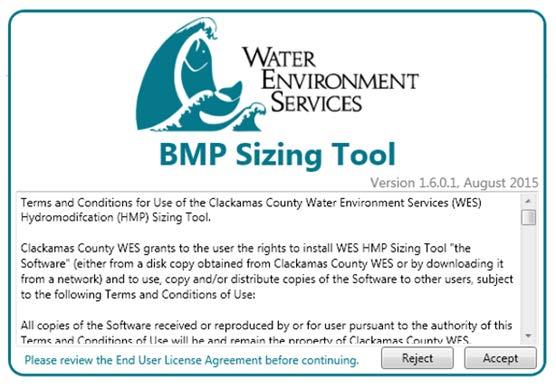

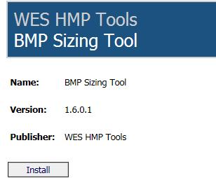

7 The BMP Sizing Tool can be obtained online at any of the following links: Once the user clicks on this link, he/she will see the screen shown in Figure 1 below, with an Install button. Figure 1. BMP Sizing Tool installation screen If the user clicks on the Install button, the box shown in Figure 2 below will pop up with the terms and conditions for using the tool. Figure 2. BMP Sizing Tool Terms and Conditions screen Revised December 2017 Page 3

8 The user should scroll through the text in this pop-up box to read the terms and conditions of use prior to accepting or rejecting the tool startup. This box will appear each time the user opens the tool. Once the user has accepted the terms and conditions, the screen shown in Figure 3 below will appear. Figure 3. BMP Sizing Tool initial screen The user should click on the File button in the top left corner of the screen to start a new file, open an existing file, or exit the application. Once the user has exited the tool, it can be accessed again from the Microsoft Windows Start bar under the All Programs>WES HMP Tools folder. Within this folder, the user should click on the icon called BMP Sizing Tool to open the application. The BMP Sizing Tool is configured to update automatically whenever a new version is provided. When opened, the application will check to see if an update exists and automatically download it from the website. This ensures that users are always running the latest version of the program. Section 4.0 Background on BMP Sizing The BMP Sizing Tool performs sizing calculations for the following BMP types: Rain Garden Filtration Rain Garden Infiltration Stormwater Planter Filtration Stormwater Planter Infiltration Vegetated Swale Filtration Vegetated Swale Infiltration Infiltrator Detention Pond The BMP Sizing Tool offers the following two design options: Treatment and flow control Revised December 2017 Page 4
9 Treatment only The BMP types that are available for each design option depend on the native soil infiltration rate at the location of the BMP facility. For example, infiltration-based facilities are only allowed in soils with design infiltration rates of at least 0.5 inches per hour. Facilities in slower draining soils require the use of underdrains to convey flows downstream. Facility design details and maintenance guides for the BMPs listed above are provided in the applicable design standards for the cities of Oregon City and Wilsonville as listed in the Introduction (Section 1.0) of this guide. Section 5.0 What Users Need to Prepare before Using This Tool Use of the BMP Sizing Tool is based on the assumption that initial site planning work has been conducted according to guidance in the applicable design standards. This includes: Step 1. Develop a Site Layout A preliminary site layout and drainage plan should be developed that incorporates the following guidelines: a. Optimize the site layout by preserving natural drainage features and laying out structures and circulation to minimize the impervious area footprint (i.e., roofs and pavement). b. Where practical, use pervious surfaces such as uncompacted gravel, porous pavers, or pervious pavement or incorporate surfaces that retain rainfall, such as vegetated landscaping. c. Direct the runoff from impervious surfaces to dispersed LID facilities, such as rain gardens, planters, and/or swales. d. Try to avoid draining large areas to a single BMP facility. BMP facilities will be most effective when they handle smaller drainage areas that are distributed throughout the site. e. Designate a percentage of the total site area for BMP facilities (typically 10% of the total site area). It is easier to reduce BMP facility sizes based on results from the BMP sizing tool than to add more BMP facility areas for a site that was designed without sufficiently accounting for BMPs. Step 2. Delineate the Discharge Management Areas (DMAs) The project area should be divided into discrete drainage basins (referred to as DMAs). DMAs should be established to define the contributing drainage area (and associated runoff) to each planned BMP facility on the site. Typically, DMA boundaries will follow grade breaks and roof ridge lines. DMAs must be accurately delineated and cover all areas of the site without overlap for adequate BMP sizing. After delineating the DMAs contributing to each of the BMPs, it will be important to further characterize the DMAs for entry into the BMP Sizing Tool. For each DMA, users should conduct the following steps: a. Divide the DMA based on pre-development conditions. If the DMA has more than one soil type, it will need to be divided accordingly. For example, a DMA may have a total of 20 acres with 10 acres of C soils and 10 acres of D soils. In this case two 10-acre DMAs will need to be entered in the tool. b. Divide the DMA based on post-development conditions. If the DMA has more than one postdevelopment condition, it will also need to be divided accordingly. For example, if one of the 10-acre DMAs from Step 2.a. includes 5 acres of impervious area in the post-development condition and 5 acres of landscape in the post-development condition, it needs to be divided into separate 5-acre DMAs. Figure 4 illustrates an example project site area delineated into DMAs. Revised December 2017 Page 5

10 The BMP Sizing Tool is based on LID principles, including the concept of prioritizing small, distributed surface vegetated facilities. As a guideline, it is recommended that the area draining into a single BMP facility should not exceed approximately 10 acres. If a facility must be designed to accommodate a larger drainage area, then it is recommended that the designer use a more detailed hydrologic modeling tool (e.g., XP-SWMM, HSPF, etc.). Figure 4. Project site area delineated into DMAs Once the site layout (Step 1) has been completed and DMAs established (Step 2), BMPs may be selected and sized to mitigate stormwater impacts. Instructions for entering DMA information into the tool and sizing BMPs are provided in the following sections. Section 6.0 Startup Using the BMP Sizing Tool After opening the BMP Sizing Tool, the user will have the option of creating a new project file or opening an existing file, as described below. 6.1 Creating a New Project File To create a new project file, users should open the File menu at the top left corner of the opening screen, select New to create a new project file (shown in Figure 5 below), and enter project information under the Project tab as instructed in Section 7.0. Revised December 2017 Page 6

11 Figure 5. File options available on the main screen 6.2 Opening and Saving Existing Project Files At any point during the BMP sizing process, the user can save a project file and reopen it later to continue working on the project. The files are small and portable for ing or transferring between computers. Project data files have an.xml format and must be reopened through the BMP Sizing Tool. Once a new or existing file has been opened, the top of the main screen of the BMP Sizing Tool will display the five tabs listed in Table 1 below. Project Tab Name Discharge Management Areas Best Management Practices Report Warnings Table 1. BMP Sizing Tool Menu Tabs Function Provides a form to enter basic information about the project site Provides a place to enter information regarding the areas on the site that are draining to planned BMP facilities Provides a place to select and size proposed stormwater management BMPs Provides a preview of the project s Summary Report and confirms the entry of project information Produces a list of warnings flagging possible input errors or insufficient BMP sizing The following sections (Sections ) provide detailed information regarding each of the five BMP Sizing Tool menu tabs. Section 7.0 Project Tab: Entering Project Site Information The Project tab provides the place to enter basic information that applies to the project site, such as name, location, jurisdiction, total site area, and contact information for the project applicant and engineer. This section should be completed prior to entering information about the site drainage and BMP layout in the Discharge Management Areas and Best Management Practices tabs, respectively. Figure 6 on the following page provides an example of project information in the Project tab as filled out by a user. Revised December 2017 Page 7
12 Additional information to input into the Project tab is described as follows: Project Name: Name of the development or portion of the development evaluated with the BMP Sizing Tool. This project name will appear in the first table at the top of the Summary Report generated by the tool. WES Log #, Zoning # and Tax Lot #: These three entries were included in the original version of the tool and are currently considered optional. These items do not show up on the Summary Report generated by the tool. Applicant Name, , and Phone: These three entries should be completed by the user. The Applicant Name will appear in the first table at the top of the Summary Report generated by the tool. Engineer Name and Engineer If these two entries are different from the Applicant Name, they should be provided here. If these fields are left blank, an assumption will be made that the project applicant is also the project engineer. Site Address: For this entry, the user should provide the general location of the project site. This information will appear in the first table at the top of the Summary Report generated by the tool. Project Type: This entry is used to describe the project type. The drop-down list provides 13 choices including commercial, industrial, singlefamily, road, feasibility, planning, etc. This selection does not result in any adjustments to BMP sizing criteria and is provided simply for informational purposes. The project type that is selected will appear in the first table at the top of the Summary Report generated by the tool. Jurisdiction: This entry was included in the original version of the tool and has not yet been updated to include Wilsonville and Oregon City. This selection does not result in any adjustments to BMP sizing criteria and is provided simply for informational purposes. The jurisdiction that is selected will appear in the first table at the top of the Summary Report generated by the tool. Projects in Oregon City or Wilsonville should select the Out of District entry. Figure 6. Example project input for the Project tab Revised December 2017 Page 8
13 Total Site Area: This entry should include the total area of the project site. It is included only for informational purposes and does not impact the facility sizing calculations. It should be provided in units of square feet. Total Pre-site Impervious Area: This entry should include the amount of impervious area (in sq ft) that currently exists on the project site area prior to the development or redevelopment activity/project. This value is included only for informational purposes and does not impact the facility sizing calculations. Total Post-site Impervious Area: This entry should include the amount of impervious area (in square feet) as proposed for the project site area that is planned for development or redevelopment. This value is included only for informational purposes and does not impact the facility sizing calculations. Stormwater Management Area: This entry should be disregarded and left blank (see Figure 6). It was included in the original version of the tool, is no longer used, and does not impact the facility sizing calculations. Any associated warnings may be disregarded as they were included in the original version of the tool and are no longer used to validate the input information. Notes: This area provides space for recording any additional notes that the user would like to save with the file. Entering notes is optional. At the bottom left corner of the screen, two boxes show the Stormwater Management Area and Sum of DMA and BMP Areas. These boxes, and any associated warning signs, may be disregarded as they were included in the original version of the tool and are no longer used to validate the input information. This will be addressed in future updates to the tool. Section 8.0 Discharge Management Areas Tab: Entering Drainage Areas 8.1 Defining Drainage Areas The Discharge Management Areas tab enables the user to enter the name, area, soil group, predevelopment surface, and post-development surface for each DMA on the project site. A DMA represents a delineated drainage area that will be routed to a BMP. It is assumed that these DMAs have already been delineated and defined by the project developer/engineer on the initial site plan drawings as described in Section 5.0 above. 8.2 Adding/Deleting DMAs To add a new DMA, the user should select the button shown highlighted in the green circle in Figure 7. Each time the user clicks on this button, a new DMA entry page will appear as a sub-tab within the Discharge Management Areas tab, as shown in Figure 7. All of the project site s DMAs can be entered here, one DMA at a time. The BMP Sizing Tool has no practical upper limit to the number of DMAs that may be entered for a given project. Multiple DMAs may be set up to drain to a single BMP facility if desired. For example, the user may set up a DMA for a parking lot, and a separate DMA for a landscaped area and direct the tool to drain both DMAs to the same BMP. This is further explained in Section 9.0 regarding the Best Management Practices tab. To delete a DMA, select the appropriate Discharge Management Areas tab and click the button shown at the lower left corner of the screen (see Figure 7). Revised December 2017 Page 9


14 Figure 7. Example project input for the Discharge Management Areas tab 8.3 Entering Data for a New DMA The information required for each DMA is based on the type of soil, pre-development surface, and postdevelopment surface associated with the selected DMA. Figure 7 includes an example with three separate DMAs entered under the Discharge Management Areas tab. For each DMA, enter the following information: DMA Name: Name the selected DMA. Provide a unique and descriptive name that distinguishes each DMA from other DMAs. Examples include Parking Area 1, Building 1, Landscape Area 1, etc. DMA Area: Enter the area of the DMA in square feet. It may be necessary to iteratively adjust DMAs based on the required BMP size (i.e., footprint area) to optimize development areas. DMAs can be revised later under the Discharge Management Areas tab when interactively sizing BMPs. However, the sum of the BMP footprint areas and the DMAs should be no greater than the total project site area. If the DMA Area field is left at the default value of 0 sq ft, the BMP Sizing Tool will add a Calculation Warning on the Warnings tab. A review should be completed in the Summary Report tab to ensure that a drainage area was entered for each DMA. DMA Soil Group: Use the drop-down menu to select a soil group for the DMA. The three soil group options provided for selection include B, C, and D. The soil type selected should be reflective of the Hydrologic Soil Group identified by a geotechnical report or the United States Department of Agriculture Natural Resources Conservation Service (USDA NRCS) maps. Type A soils are not provided in the tool as they compose only a very minimal percentage of all the soils within these jurisdictions. Visit for more information about the soil groupings. Calculations related to runoff from the DMAs are based on the soil types that are selected here. Pre-development Surface: Select the pre-development surface from one of the options provided in the drop-down menu. The options include forested, grass, and impervious. The type of predevelopment surface that must be selected may be dependent upon historical vegetation information provided by the relevant jurisdiction. Please see the relevant design standards documentation, listed in the Introduction (Section 1.0) for assumptions that should be made regarding pre-development surfaces. Revised December 2017 Page 10
15 Post-development Surface: Select the post-development surface from one of the options provided in the drop-down menu. In addition to conventional concrete, asphalt paving, and roofs, the tool includes post-development surface types that result in reduced runoff volumes. Table 2 lists those cover types and their associated cover (runoff) coefficients. As an example, if porous asphalt is selected as the post-development surface, the tool will assume 0.1 times the impervious area that is entered when sizing the BMP. Refer to the relevant design standards documentation listed in the Introduction (Section 1.0) for post-development surface types that may be used for sizing BMPs. Table 2. Post-development Surface Types and Associated Cover Coefficients Surface Types Cover Coefficients Grass 0.29 Forested 0.20 Roofs 1.00 Conventional Concrete or Asphalt Paving 1.00 Pervious Concrete or Pavement: Parking 0.80 Pervious Concrete or Pavement: Drive Aisle 0.90 Crushed Aggregate 0.80 Porous Asphalt 0.10 Open and Porous Pavers 0.10 Grouted Unit Pavers 1.00 Solid Unit Pavers 0.50 Landscape, B-Soil 0.30 Landscape, C-Soil 0.50 Landscape, D-Soil 0.70 As with the Project tab, at the bottom left corner of the screen, two boxes show the Stormwater Management Area and Sum of DMA and BMP Areas. These boxes, and any associated warning signs, may be disregarded as they were included in the original version of the tool and are no longer used. Section 9.0 Best Management Practices Tab: Selecting BMP Types and Conducting BMP Sizing The Best Management Practices tab is used to select the proposed BMP facility types for the project site and to calculate the required sizes of stormwater management BMPs. 9.1 Adding a New BMP The Best Management Practices tab contains separate buttons for adding and deleting BMPs, as shown in Figure 8. (Note that the button to delete a BMP does not show up until a BMP has been added.) Revised December 2017 Page 11

16 When the user clicks on the appears: Rain Garden Stormwater Planter Vegetated Swale Infiltrator Detention Pond Figure 8. Example project input for BMP selection and sizing button, a menu of the following five BMP options Once the user selects a BMP option, a screen will appear that is specific to that BMP type. The user must enter a name for the BMP facility to distinguish it from any other BMP facilities in the Summary Report. An example might be Rain Garden for Parking Lot 1, Detention for South Lots, etc. 9.2 LID Facility Sizing Rain gardens, stormwater planters, vegetated swales, and infiltrators are referred to as LID facilities. The BMP Sizing Tool uses different methods for sizing LID facilities and detention ponds. The following text is focused on LID facilities. For sizing detention ponds, refer to Section 9.3 Treatment Type: After selecting a BMP type and entering a BMP name, select the treatment type from the following two choices: 1. Treatment and flow control: Select this option to size a BMP to meet both the water quality and flow control criteria as outlined in the applicable design standards. Specifically, the facility will be sized to address peak flow duration matching for flows ranging from 42 percent of the 2-year peak flow to the 10-year peak flow. It will also be sized to ensure treatment of 80 percent of the average annual runoff. Revised December 2017 Page 12
17 2. Treatment only: Select this option for those cases where flow control is not required. For exemptions to the flow control requirement, see Section (c) of Wilsonville s Public Works Standards, and Section H. of Oregon City s Design and Construction Standards. When choosing this option, facilities are sized to treat 80 percent of the average annual runoff. If the design goal changes, it is possible to switch treatment type without losing any information that has been entered. When the treatment type is changed, the tool dynamically updates any computed minimum BMP sizes. Facility Infiltration Rate: The next step when adding a new BMP is to specify the design infiltration rate at the site of the BMP facility. Infiltration testing is required to obtain this infiltration rate. Infiltration testing requirements are provided in the following documents: City of Oregon City, Stormwater Grading and Design Standards: Section 4.5 and Appendix D City of Wilsonville, Storm and Surface Water Design and Construction Standards: Section and Appendix B For rain gardens, planters, and swales, there are two facility configuration types (filtration or infiltration). The BMP Sizing Tool will automatically select the facility configuration type depending on the Facility Infiltration Rate that is provided by the user. For facility infiltration rates of 0.5 inch per hour (in./hr) and greater, the tool will specify an infiltration facility (i.e., Rain Garden-Infiltration, Stormwater Planter- Infiltration, or Vegetated Swale-Infiltration). For facility infiltration rates that are less than 0.5 inch per hour or lined, the tool will specify filtration facilities (i.e., Rain Garden Filtration, Stormwater Planter Filtration, or Vegetated Swale Filtration). Infiltration facilities use only infiltration to manage runoff. Filtration facilities include piped underdrain systems and orifice controls. Table 3 below lists the infiltration rate options used for BMP sizing by facility type. Table 3. Facility Infiltration Rate Options Used for BMP Sizing Infiltration/Filtration Facility Type Facility Soil Sub-group Lower Infiltration Rate (in./hr) Upper Infiltration Rate (in./hr) A No upper bound Infiltration B B B C Filtration C C D The infiltration rate that is entered here is separate from the soil type entered under the Discharge Management Areas tab. The soil type entered under the Discharge Management Areas tab is used in calculations related to runoff generated from the DMA. The infiltration rate that is entered in the Best Management Practices tab is used in calculations related to the effectiveness of the planned BMP facility in managing flows. Revised December 2017 Page 13
18 Upstream Discharge Management Areas: When a BMP is added, the areas that drain to the facility (i.e., the upstream DMAs) must be selected. To do this, click on the button and select DMAs from this list created under the Discharge Management Areas tab. If a DMA has already been selected to drain to another BMP facility, the DMA will still appear in the list, but the ability to select this DMA will be disabled. The sum of DMAs planned for routing to one BMP should not exceed 10 acres (435,600 sq ft). Minimum Size: After selecting the treatment type, facility infiltration rate, and upstream DMAs, the BMP Sizing Tool will calculate the minimum BMP size (in square feet of surface area) required to manage runoff from the selected upstream DMA(s). For LID facilities, the BMP Sizing Tool calculates the minimum facility size based on a lookup table of sizing factors. A sizing factor is the percentage of impervious area and represents the surface area required for the selected LID facility. For example, if a DMA has an impervious area of 10,000 sq ft and the selected LID facility uses a sizing factor of 6 percent, then the surface area required for the LID facility is 600 sq ft. Sizing factors vary based on DMA soil types, pre-development conditions, and infiltration rates at the location of the LID facility. Sizing factors were developed by conducting continuous-simulation modeling and flow duration matching for 1-acre unit areas with each potential combination of conditions. Tables showing the sizing factors used in the BMP Sizing Tool are provided in Appendix B. The BMP Sizing Tool calculates an area-weighted sizing factor based on the different DMAs that are entered. Design Flow/Orifice Size: The BMP Sizing Tool also provides the design flow and the orifice size for the underdrain pipe for filtration type facilities. In some cases, the BMP Sizing Tool may recommend a control orifice that is smaller than allowed by a given jurisdiction. Consult with the reviewing agency to determine if the calculated orifice size should be increased to address facility maintenance concerns. Design Note: The BMP sizes that are provided by this tool are applicable only for BMPs that are designed and constructed with the specific dimensions as provided in the City of Oregon City s and Wilsonville s details. See Appendix C of the Oregon City Design and Construction Standards and Wilsonville s Detail Drawing Index for Stormwater at the following links: The facility details include design specifications such as, but not limited to, minimum drain rock depths, minimum growing medium depths, minimum widths, and maximum side slopes. Design specifications are also shown in Table 4 below. Revised December 2017 Page 14
19 Facility Stormwater Planter - Filtration Table 4. BMP Dimensions Required for the Sizing Tool to Apply Drain Rock, min. in. Separation Layer, in. Growing Media, min. in. Ponding Depth, in. Freeboard, min. in. Side Slope, ratio Bottom Width, min. in Liner If required Stormwater Planter - Infiltration No Rain Garden - Filtration :1 max 24 If required Rain Garden - Infiltration N/A 3:1 max 24 No Vegetated Swale - Filtration :1 max 24 If required Vegetated Swale - Infiltration N/A 3:1 max 24n No Detention Pond Per sizing model (12 in. min.) 12 a 3:1 max N/A If required a. The surface area of the detention pond, the filtration rain garden and the filtration swale sized by the tool does not take freeboard into account. In addition, see Note 12 on the Detention Pond detail regarding an emergency spillway. Drains to Pond: If outflow from any of the planned BMP facilities drains to a downstream detention pond, the user should click on the Drains to Pond menu option and select the appropriate downstream pond. A detention pond must be created in the Best Management Practices tab first for it to appear as a menu option. See the following section for adding a detention pond as a BMP facility. Proposed Size: Enter the surface area of the proposed BMP facility. This box is used to verify the proposed design. If the proposed size (as entered by the user) is less than the minimum size (as calculated by the tool), the proposed size entry box will turn red and a warning will appear in the Warnings tab. In addition, it should be noted that additional surface area will need to be added to the BMP surface area provided by the tool to accommodate any required freeboard for the detention pond, filtration swale and filtration rain garden. 9.3 Detention Pond Sizing The sizing procedure for detention ponds is different from LID facilities. As described in the previous section, the BMP sizing for LID facilities is based on a lookup table of sizing factors that were developed from prior continuous-simulation modeling iterations. For detention pond sizing, the BMP Sizing Tool uses a more dynamic and iterative procedure. For the DMA conditions that are entered by the user, the BMP Sizing Tool constructs a pre- and post-project (unmitigated) long-term runoff time series. The post-project, long-term runoff time series is then routed through the detention pond (with dimensions established by the user) using a level pool routing technique. Flow duration curves are calculated for each runoff time series. For the detention pond to be sized appropriately, the flow duration curve from the mitigated outflow will need to be equal to or lower than the flow duration curve representing pre-project conditions for flows ranging from 42 percent of the 2-year peak flow to the 10-year peak flow. Revised December 2017 Page 15
20 Figure 9 provides a screen shot from the BMP Sizing Tool to illustrate the information required by the user for sizing a detention pond. Figure 9. Example input/output for detention pond sizing For detention pond sizing, the facility name, facility infiltration rate, and treatment type should all be entered as described for the LID facilities above. Two tabs initially appear in the center of the screen for the Detention Pond sizing: Geometry and Tributary Areas. Information should be entered as follows. Tributary Areas tab: Select the DMAs that drain to the detention pond. When the user clicks on this tab, the following two boxes appear: Upstream Discharge Management Areas: The top box provides a list of DMAs that have been entered by the user under the Discharge Management Areas tab. If a DMA has been selected as draining to another BMP facility, it will appear in this list but will not be available for selection. The user should select the DMAs that drain directly to the pond. Upstream Low Impact Developments: The lower box provides a list of LID facilities that have been entered by the user. In some cases, the user may want to route discharge from an upstream LID facility to a detention pond. The LID facility may be selected here. Alternatively, the user can select the Drains to Pond option for upstream LID facilities. If the upstream LID facility was sized for Treatment and Flow Control, then it is assumed that the discharge from the LID facility post-development conditions is the same as what it would be for predevelopment conditions and no flow control would be required for those areas in sizing of the detention pond. Revised December 2017 Page 16
21 Geometry tab: The BMP Sizing Tool provides two types of pond configuration options: simple and custom. For each configuration option, the BMP Sizing Tool routes the post-development flow through the pond, performs statistical analyses for flow duration and peak flow criteria, and reports if the pond is sized adequately. The features of both options are described below: Simple Geometry: In this mode, the user can choose to size the pond either manually or automatically by selecting the appropriate Sizing Mode. In automatic sizing, the user inputs either Surface Area or Depth, and the BMP Sizing Tool calculates the required pond size and designs the outlet structure using a built-in pond optimization algorithm. If Depth is chosen from the drop-down menu, the user must enter a surface area and side slope. Once the button is selected, the sizing tool will calculate the depth required for the pond given the user-supplied surface area and slope. If Surface Area is chosen from the drop-down menu, the user must enter a depth and side slope. Once the button is selected, the sizing tool will calculate the surface area required for the pond given the usersupplied depth and side slope. For ponds sized using Simple Geometry, the tool assumes that the pond is square-shaped. If the user-specified slope and selected dimensions do not allow the pond to be sized adequately such that the bottom area becomes zero before reaching the required depth, the following error message will appear: The user must increase the surface area or decrease the side slope to ensure sufficient surface area for the pond bottom. Note that some jurisdictions do not allow side slopes to exceed 3H:1V. Once the dimensions of the pond are adequate, the following message will appear: Custom Geometry: In this mode, the user can manually size and develop a custom pond design with a custom outlet configuration that differs from the one provided by the tool. Using this option, the user will need to independently assess the stage-storage-discharge relationship for the custom pond. The user enters a data table of depth, surface area, and total outflow values (Figure 10). These values need to be calculated outside the tool using an Excel spreadsheet or other sizing tool such as HydroCAD. Data may be entered individually for each row or the whole table may be copied and pasted from Excel. Pond sizing is checked by clicking the button. The tool routes the post-project hydrograph through the custom stage-storage-discharge table and determines whether the provided size is adequate for meeting the flow duration criteria. If the pond is too small, the following error message will appear: In this case, the user will need to revisit the stage-storage-discharge relationship for the pond. This may require increasing the capacity of the pond, resulting in a larger surface area or adjusting the outlet structure to reduce the discharge (outflow) associated with the specific stage. See the Warnings tab (Section 11.0) for more information. Once the design of the pond is adequate, the following message will appear: Revised December 2017 Page 17

22 Figure 10. Custom Detention Pond Sizing Data Input Once the Tributary Areas tab and Geometry tab have been populated, the following information is developed and documented via additional tabs in the tool. Revised December 2017 Page 18

23 Outlet Structure: For ponds sized adequately using Simple Geometry, the Outlet Structure tab will be generated to summarize the required outlet dimensions for the pond. The outlet dimensions are automatically updated for each iterative step during pond sizing. Inverts and dimensions of lower orifice, upper orifice, and overflow weir are provided, as shown in Figure 11 below. For locations of the various dimensions, reference the Facility Schematic tab. Facility Schematic: For ponds sized using Simple Geometry, the schematic is a generic representation of the detention pond facility sized by the tool. The figure depicts the main features of the outlet structure with the locations of their inverts. The overflow weir is at 1 foot below the 10-year pond water surface elevation. It is assumed that the pond will need to include additional freeboard (typically 1 foot) above the 10-year water surface elevation. Figure 11. Outlet structure dimensions of the detention pond designed by the tool Revised December 2017 Page 19
24 Flow Duration: For each iterative step during pond sizing, the tool compares the pre-project and postproject flow duration. The flow duration comparison curves are displayed when the user clicks the Flow Duration tab, shown in Figure 12 and indicated by the green arrow. The flow duration comparison is available for ponds sized with both the Simple Geometry and Custom Geometry options. Figure 12 also shows the flow duration curve for the flow range of interest, i.e., between the lower flow threshold (0.42Q2) and the upper flow threshold (Q10). Notice that the Mitigated, Post development curve falls below the Pre-development curve for ponds sized adequately. Figure 12. Example flow duration comparison curves displayed by the tool Revised December 2017 Page 20
25 Peak Flow Frequency: Similar to flow duration curves, the BMP Sizing Tool compares the pre-project and post-project flow frequency. The flow frequency comparison curves are displayed when the user clicks the Peak Flows tab, as shown in Figure 13 and indicated by the green arrow. Mitigated, Postdevelopment peak flows are lower than the Pre-development flows for ponds sized adequately. The flow frequency comparison is available for ponds sized with both the Simple Geometry and Custom Geometry options. Figure 13. Example peak flow frequency comparison curves displayed by the tool Output Files: For either the Simple Geometry or Custom Geometry pond sizing, a selection is provided for providing output files for the time series data. If the user checks the box that says output intermediate time-series data to file, the tool will save files for both undeveloped and post-developed mitigated conditions. Files include flow duration curves, flow events, and runoff data. The output folder path entry field in the tool allows the user to specify the location for files to be saved. Revised December 2017 Page 21

26 Section 10.0 Report The Report tab captures all relevant information about the project in one location. View the Summary Report by clicking the Report tab. If the user decides to add a detention pond and the pond is undersized, a warning will pop up and a report will not be generated. Additionally, the user may export and save the Summary Report in a PDF file format by choosing the Export to PDF File option under the File menu (Figure 14). Figure 14. Summary report in PDF file format Revised December 2017 Page 22

27 Section 11.0 Warnings The Warnings tab collects and reports important calculation warnings and errors for the project. The information in this section may include missing or zero data, BMPs that are undersized, mismatches between total project area and DMA or BMP areas, and other relevant messages. The Warnings tab is updated dynamically any time project information is changed and is a useful way to check the validity and completeness of the project input. The information is also included with the Summary Report upon export. An example Warnings tab display is shown in Figure 15. Figure 15. Warnings tab message example Message displayed when the total drainage area does not match the sum of proposed DMA and BMP areas. Revised December 2017 Page 23
28
29 Appendix A: Responses to BMP Sizing Tool Questions Revised December 2017 Page A-1
30
31 Appendix A Responses to BMP Sizing Tool Questions As the development community has been using the BMP Sizing Tool, questions and requests for further clarification have arisen. This appendix provides a list of those requests and associated responses. What is the basis for the LID facility sizing calculations? In developing the BMP Sizing Tool, LID BMPs were evaluated using a continuous-simulation hydrologic model (Hydrological Simulation Program-Fortran [HSPF]) that runs a long-term (1947 to 2007) record of historical hourly rainfall data. For each pre-development and post-development surface condition, a 1-acre hypothetical drainage area (unit parcel) was defined. The long-term hourly rainfall record was run through the HSPF model to obtain pre-development flows for each unit parcel. For each facility type and facility infiltration rate, the long-term hourly rainfall record was also run through the HSPF model to obtain post-development flows for a 1-acre impervious area. Flow duration curves reflecting runoff from each pre-developed and post-developed unit parcel were then compared to each other. The HSPF model was used to size facilities (based on facility dimensions provided in the facility details) to manage the post-development flows so that outflow from a facility matched the pre-development flow duration curve for the range of flows considered to have the greatest erosive impact on open-channel systems (42 percent of the 2-year peak flow to the 10-year peak flow). Once a facility was sized for the 1-acre unit parcel, a sizing factor was developed. The sizing factor is the required surface area of the facility by the 1-acre unit area for specific combinations of runoff and infiltration conditions. These sizing factors are provided in Appendix B for both the flow control and treatment and treatment only sizing options. For LID BMPs, the BMP Sizing Tool acts as a calculator, drawing on these sizing factors to size facilities. How does the BMP Sizing Tool deal with the time of concentration (TOC) for runoff from the drainage areas used to size BMPs? The long-term runoff hydrographs mentioned above were generated from the hypothetical 1-acre unit drainage areas using HSPF s runoff routing technique. The routing technique is based on the Chézy- Manning equation and an empirical expression that relates outflow depth to the facility storage. The calculations for routing in the model required the following three inputs: NSUR = Manning's n (roughness coefficient) for the overland flow plane LSUR = length of the overland flow plane (ft) SLSUR = slope of the overland flow plane (ft/ft) TOC is not used by the HSPF model for routing flow as it is with more traditional runoff approaches, such as the rational method, which is based on a synthetic 24-hour unit hydrograph instead of a longterm runoff hydrograph. Alternatively, the routing is calculated as a function of the three variables listed above. Traditional methods of calculating flow are focused on a different outcome from the continuoussimulation method, which is used as the basis for the BMP Sizing Tool. The outcome of traditional methods is typically a single peak flow used to size conveyance systems, which would be more highly sensitive to TOC. The BMP Sizing Tool looks at durations of flows over the long term to see how they compare to each other for pre- and post-development conditions. Revised December 2017 Page A-3
32 Appendix A TOCs vary depending on slope; so how is slope taken into account in the sizing tool? When the tool was originally being developed for Clackamas County WES, a sensitivity analysis was conducted to see how the slope of the facility drainage areas would affect flows. Hydrologic continuous simulations were run for a unit 1-acre parcel of grass land cover and C soils for three different slopes (5 percent, 10 percent, and 15 percent). The sensitivity analysis was not conducted for forested conditions because grass cover (which generates more runoff) would be more sensitive to changes in slope than forested conditions. After reviewing the sensitivity analysis results for flows, WES elected not to include multiple options in the tool for slope. WES instead elected to assume a 5 percent slope for all pre-developed surface conditions (consistent with the Johnson Creek HSPF model on which the tool is based) and a 1 percent slope for the post-developed impervious areas. The sensitivity analysis was conducted on the drainage area runoff only and not on the ultimate BMP sizing factor. Runoff parameters for various land surfaces used in the tool were based largely on the calibrated parameters from a Johnson Creek model (previously developed by WES) that did not vary slope; all pervious surfaces were assumed to have a 5 percent slope. In keeping with 5 percent for the BMP Sizing Tool model runs, the tool remained consistent with the calibrated parameters from the Johnson Creek model, which included parameters for infiltration and soil storage. If the user has varying types of post-development surface covers in the drainage area, how can he/she route these various surface covers/drainage areas to one facility? Yes. If there are multiple types of post-development surface covers on the site, each of the areas should be delineated separately and entered separately in the BMP Sizing Tool under the Discharge Management Areas tab. For example, if a school site has three separate post-development areas (e.g., landscape, parking lot, roof) draining into a single stormwater management facility, enter each of these three areas as individual DMAs. Then, create a BMP facility (e.g., a vegetated swale), and add multiple Upstream DMAs by repeatedly selecting the Add upstream DMA. box in the Best Management Practices tab. What flows should developers use to size conveyance pipes on the downstream end of a detention facility? The BMP Sizing Tool sizes facilities to manage the 10-year peak flow (based on continuous simulation.) However, most design standards require conveyance systems to be sized for the peak flow from a 25-year, 24-hour design storm. There are two general approaches to size conveyance systems downstream of detention facilities. The first option would be to size the conveyance pipe for the 25-year peak flow discharging from the upstream drainage area without accounting for any mitigation of flows from detention. This would be the most conservative option. The second option would be to take the configuration of the facility sized using the BMP Sizing Tool and use a separate tool/model such as Storm Water Management Model (SWMM) to estimate outflows from the facility for a traditional Soil Conservation Service (SCS) Type 1A 24-hour, 25-year event. Then, the conveyance downstream of the facility could be sized for the flow exiting the facility during a 25-year design event. This option would provide credit for flows mitigated by the detention facility. The disadvantage to this option is that it would require a fair amount of sophistication on the part of a design engineer to simulate the various functions of the detention facility including surface storage, soil media storage, and infiltration. Individual jurisdictions would need to be consulted regarding the allowable option. Revised December 2017 Page A-4
Chapter 4 - Preparation of Stormwater Site Plans
 Chapter 4 - Preparation of Stormwater Site Plans The Stormwater Site Plan is the comprehensive report containing all of the technical information and analysis necessary for the City to evaluate a proposed
Pollutant Removal Benefits
 Bioswales Bioswales Similar to biocells, but have a slight, but positive grade toward an outlet Designed to convey the WQv event at very low velocities Promote filtration through native vegetation, infiltration
Stormwater Control Plan: Small (Tier 1) Land Development Project
 Land Development Project") Stormwater Control Plan: Small (Tier 1) Land Development Project Project ID for Tracking (for City Staff only): The California Regional Water Quality Control Board for the Central Coast Region (Water Board)
Stormwater Control Plan: Small (Tier 1) Land Development Project Project ID for Tracking (for City Staff only): The California Regional Water Quality Control Board for the Central Coast Region (Water Board)
October 7, City of Thornton 9500 Civic Center Drive Thornton, CO (303) RE: Maverik Thornton, CO - Drainage Report
 RE: Maverik Thornton, CO - Drainage Report") October 7, 2016 City of Thornton 9500 Civic Center Drive Thornton, CO 80229 (303) 538-7295 RE: Maverik Thornton, CO - Drainage Report As per your request, we are submitting to you the drainage report and
October 7, 2016 City of Thornton 9500 Civic Center Drive Thornton, CO 80229 (303) 538-7295 RE: Maverik Thornton, CO - Drainage Report As per your request, we are submitting to you the drainage report and
Draft Rhode Island Stormwater Design and Installation Standards Manual
 Draft Rhode Island Stormwater Design and Installation Standards Manual Summary The May 2009 Public Review Draft version of the RI Stormwater Design and Installation Standards Manual consists of approximately
HEALTH SCIENCES BUILDING REDEVELOPMENT PROJECT
 INTRODUCTION In recent years, the University of Cincinnati (University) has demonstrated a commitment to identifying and implementing sustainable goals and objectives throughout University s Uptown Campuses.
Bioretention cell schematic key
 Bioretention Cells Bioretention cell schematic key 1 3 Hardwood mulch 2 Curb cut 3 18-30 Modified soil 4 Stone aggregate choker layer 5 Stone aggregate base layer 6 Subdrain 7 Undisturbed soil 8 Overflow/Cleanout
Huntington Stormwater Utility
 Huntington Stormwater Utility Stormwater Management & Sediment and Erosion Control Requirements for Construction Sites Authorized by Huntington City Code Articles: 971, 970, 930, 935, 955, Revised April
C.3 STORMWATER TECHNICAL GUIDANCE. Table of Contents. Glossary... viii. Chapter 1 Introduction/How to Use this Handbook
 C.3 STORMWATER TECHNICAL GUIDANCE Table of Contents Glossary... viii Chapter 1 Introduction/How to Use this Handbook... 1-1 1.1 Purpose of this Handbook... 1-1 1.2 What is the Countywide Program?... 1-2
5. LOW IMPACT DEVELOPMENT DESIGN STANDARDS
 5. LOW IMPACT DEVELOPMENT DESIGN STANDARDS Low Impact Development (LID) requires a shift in stormwater management away from conveying runoff to a small number of downstream points through hydraulically
Three Rivers Park District Administration Center Rain Garden
 Three Rivers Park District Administration Center Rain Garden Introduction There are significant changes to the hydrologic regime and nutrient loading following urban and industrial development. The post-development
BMP Siting Tool. Step-by-Step Guide
 BMP Siting Tool Step-by-Step Guide ArcGIS 10.1 Service Pack 1 (Build 3143) Prepared by: Tetra Tech, Inc. 10306 Eaton Place, Suite 340 Fairfax, VA 22030 January 2013 Contents 1 Getting Started... 1 1.1
HOW TO MODEL IMP FACILITIES USING BAHM. By Douglas Beyerlein, P.E., Clear Creek Solutions, Inc. Introduction
 HOW TO MODEL IMP FACILITIES USING BAHM By Douglas Beyerlein, P.E., Clear Creek Solutions, Inc. Introduction IMP (Integrated Management Practice) facilities are small-scale stormwater control facilities
New Tools/Resources for
 New Tools/Resources for C.3 Stormwater Compliance Laura Prickett, AICP, EOA, Inc. Santa Clara Valley Urban Runoff Pollution Prevention Program Outline of Presentation Updated C.3 Handbook Handbook outline
STAFFORD TRACT NORTH OF US90A 1.0 INTRODUCTION 1.1 OBJECTIVE
 1.0 INTRODUCTION 1.1 OBJECTIVE This report, prepared for submittal to TxDOT, analyzes existing and proposed detention facilities draining into the TxDOT US90A storm sewer system. The results of the detailed
Attachment 2: Permeable Pavement Design Guidelines
 Attachment 2: Permeable Pavement Design Guidelines Design of permeable pavement systems is critical if they are to function properly and efficiently. The area and shape are dependent on the site design,
BRISBANE BAYLANDS INFRASTRUCTURE PLAN FEBRUARY 2011 APPENDIX O DRAFT
 BRISBANE BAYLANDS INFRASTRUCTURE PLAN FEBRUARY 2011 APPENDIX O DRAFT PRELIMINARY STORM DRAIN CALCULATIONS ASSOCIATED WITH BRISBANE BAYLANDS REDEVELOPMENT BRISBANE, CALIFORNIA Prepared by BKF Engineers
Appendices: Glossary. General Terms. Specific Terms. Low Impact Development Approaches Handbook
 67 67 General Terms Specific Terms 66 Low Impact Development Approaches Handbook The vocabulary of low impact development is evolving, and many terms are used interchangeably and to describe the same or
TENNESSEE GAS PIPELINE COMPANY, L.L.C.
 TENNESSEE GAS PIPELINE COMPANY, L.L.C. HYDROLOGIC AND HYDRAULIC CALCULATIONS FOR ACCESS ROADS ALONG THE CONNECTICUT PIPELINE EXPANSION PROJECT CONNECTICUT LOOP Submitted by: Tennessee Gas Pipeline Company,
New Development Stormwater Guidelines
 New Development Stormwater Guidelines CITY OF MOUNTLAKE TERRACE Table of Contents Introduction... 2 Ecology s Minimum Requirements for stormwater management... 2 Description of the 9 Minimum Requirements...
Preparing a Stormwater Control Plan for a Small Land Development Project
 Preparing a Stormwater Control Plan for a Small Land Development Project Addendum to the Stormwater C.3 Guidebook December 1, 2012 Introduction As of December 1, 2012, development projects that create
J. Paul Guyer, P.E., R.A.
 J. Paul Guyer, P.E., R.A. Paul Guyer is a registered civil engineer, mechanical engineer, fire protection engineer, and architect with over 35 years experience in the design of buildings and related infrastructure.
Post-Construction Stormwater Management Checklist* (5,000 SF or Greater)
") Applicability: Required for projects that create and/or replace 5,000 square feet or greater of impervious surface (i.e. asphalt roads, concrete structures, building area, sidewalks, etc.). Impervious
Applicability: Required for projects that create and/or replace 5,000 square feet or greater of impervious surface (i.e. asphalt roads, concrete structures, building area, sidewalks, etc.). Impervious
General Technical Guidance for Treatment Measures
 Chapter 5 General Technical Guidance for Treatment Measures The technical guidance in this Chapter applies to all types of stormwater treatment measures. This chapter contains general technical information
ANSWER KEY MGSFlood v WWHM2012 (released 5/15/2015)
") ANSWER KEY MGSFlood v. 4.35 --- WWHM2012 (released 5/15/2015) Name: Date: Module 6.0: Advanced Topics in LID Design: Hydrologic Modeling General instructions: You may model facility dimensions to the nearest
ANSWER KEY MGSFlood v. 4.35 --- WWHM2012 (released 5/15/2015) Name: Date: Module 6.0: Advanced Topics in LID Design: Hydrologic Modeling General instructions: You may model facility dimensions to the nearest
CHECKLIST FOR PHASE II DRAINAGE REPORT
 I. COVER SHEET CHECKLIST FOR PHASE II DRAINAGE REPORT A. Name of Project B. Address C. Owner D. Developer E. Engineer F. Submittal date and revision dates as applicable II. GENERAL LOCATION AND DESCRIPTION
DRAFT DESIGN CRITERIA STORMWATER TREATMENT STANDARDS CITY OF OVERLAND PARK
 DRAFT DESIGN CRITERIA STORMWATER TREATMENT STANDARDS CITY OF OVERLAND PARK A. Authority As set forth in the Overland Park Municipal Code (OPMC), Chapter 16.210, the Director of Planning and Development
A P P E N D I X D. Project Stormwater Plan Worksheets
 A P P E N D I X D Worksheets for Section 1: Basic Project Information This worksheet must be filled out for all projects required to implement the 2015 Post- Construction Stormwater Standards Manual. A
General Technical Guidance for Treatment Measures
 Chapter 5 General Technical Guidance for Treatment Measures This Chapter contains guidance on: Hydraulic sizing criteria, Applicability of non-landscape based treatment measures, Using Manufactured Treatment
MANUAL OF DESIGN, INSTALLATION, AND MAINTENANCE REQUIREMENTS FOR STORMWATER MANAGEMENT PLANS
 MANUAL OF DESIGN, INSTALLATION, AND MAINTENANCE REQUIREMENTS FOR STORMWATER MANAGEMENT PLANS May 2007 SECTION 1 Responsibility of Applicant TABLE OF CONTENTS A. Stormwater Management Plan Required Information
4. CONCEPT PLAN DEVELOPMENT
 4. CONCEPT PLAN DEVELOPMENT Concept Plan Step 1: Identify Site Constraints and Opportunities Review the existing site to identify constraints and opportunities for GI Practices to meet the RRv. Constraints
Directors Rules for Seattle Municipal Code, Chapters Stormwater Code
 Directors Rules for Seattle Municipal Code, Chapters 22.800 22.808 Stormwater Code Requirements for Green Stormwater Infrastructure to the Maximum Extent Feasible for Single-Family Residential and Parcel-Based
Stormwater Technical Guide
 Stormwater Technical Guide Compliance with Stormwater Post-Construction Requirements in Santa Barbara County Dan Cloak, Principal Dan Cloak Environmental Consulting January 9, 2014 Introduce yourself Name
STORMWATER SITE PLAN INSTRUCTIONS AND SUBMITTAL TEMPLATE Medium and Large Projects
 DEPARTMENT OF COMMUNITY DEVELOPMENT 621 Sheridan Street, Port Townsend, WA 98368 Tel: 360.379.4450 Fax: 360.379.4451 Web: www.co.jefferson.wa.us/communitydevelopment E-mail: dcd@co.jefferson.wa.us STORMWATER
Figure 1 Cypress Street Study Area Location Map
 July 20, 2016 TO: FROM: Jim Massarelli Director of Engineering Jeff Julkowski, PE Michael Burke, PE SUBJECT: Cypress Street Study Area Stormwater Analysis (CBBEL Project No. 16-0058) At the request of
2008 SWMM, 2010 Revision City of Tacoma
 2008 SWMM, 2010 Revision City of Tacoma 2.2.3.1 BMP L630 Rain Gardens Purpose and Definition Bioretention areas are shallow stormwater retention facilities designed to mimic forested systems by controlling
Chapter 14. Stormwater Quality Introduction
 14.0 Introduction This chapter addresses requirements and design criteria related to post-construction stormwater best management practices (requirements for construction erosion and sediment control are
STORMWATER REPORT FOR WALMART SUPERCENTER STORE # SIOUX FALLS, LINCOLN COUNTY, SOUTH DAKOTA BFA PROJECT NO
 STORMWATER REPORT FOR WALMART SUPERCENTER STORE # 2443-00 SIOUX FALLS, LINCOLN COUNTY, SOUTH DAKOTA BFA PROJECT NO. 3286 March 1, 2012 I hereby certify that this engineering document was prepared by me
Appendix D - Technical Design Criteria for BMPs
 Appendix D - Technical Design Criteria for BMPs City of Wayzata Page 3 On-site infiltration features Definitions and Scope: Infiltration facilities are constructed basins or depressions located in permeable
STORMWATER MANAGEMENT CODES ANALYSIS RICHLAND COUNTY, SC SITE PLANNING ROUNDTABLE
 STORMWATER MANAGEMENT CODES ANALYSIS RICHLAND COUNTY, SC SITE PLANNING ROUNDTABLE Codes analyses for each subcommittee were completed to assist participants of the Richland County Site Planning Roundtable.
03/10/2015 PROGRAM OVERVIEW OVERVIEW OF PROGRAM
 1 PROGRAM OVERVIEW 2012: Public and private partners engage state legislature to fund program June 2012: LID Training Steering Committee convened 2012 2013: Washington State LID Training Plan developed:
Article 20 Stormwater Management
 Article 20 Section 20.01 Intent Article 20 The purpose of this Article is to protect the health, safety, and general welfare of the citizens by requiring compliance with accepted standards and practices
Example Stormwater Control Plan For a Residential Subdivision Project. Whispering Pines Lane Anytown, USA
 Example Stormwater Control Plan For a Residential Subdivision Project Whispering Pines Lane Anytown, USA December 2, 2015 XYZ Corporation Jane Jones, 707-555-1212 This example prepared by Dan Cloak Environmental
Modeling Rain Garden LID Impacts on Sewer Overflows
 7 Modeling Rain Garden LID Impacts on Sewer Overflows Uzair (Sam) M. Shamsi In September 2010, the U.S. Environmental Protection Agency (USEPA) released a new version (5.0.021) of Storm Water Management
Evaluating Low Impact Development Practices for Stormwater Management on an Industrial Site in Mississippi
 Evaluating Low Impact Development Practices for Stormwater Management on an Industrial Site in Mississippi Dennis S. Painter, Tennessee Valley Authority, Nashville, Tennessee Donald Becker, Tennessee Valley
Selecting Appropriate Stormwater Control Measures for Your Development Project
 Phase II Post-Construction Stormwater Requirements Workshop - February 10, 2014 Selecting Appropriate Stormwater Control Measures for Your Development Project Jill Bicknell, P.E., EOA, Inc. Outline of
Lincoln 270. City of Lincoln. Stormwater Management Plan. April 2, 2013
 Lincoln 270 City of Lincoln Stormwater Management Plan April 2, 2013 # 2005.48 Prepared By: Civil Engineering Solutions, Inc. 590 E Street Lincoln, Ca 95648 (916) 645 5700 1.0 Background: The project site
General Technical Guidance for Treatment Measures
 Chapter 5 General Technical Guidance for Treatment Measures The technical guidance in this Chapter will help you with proper sizing and design concepts for various types of stormwater treatment measures.
Post Construction BMPs
 Post Construction BMPs Why are Post Construction BMPs important? With increased development brings the increase of impervious cover Parking lots, rooftops, driveways Storm water runoff volume increases
City of Vallejo. Stormwater Control C.3 Compliance Information. Addendum to C.3 Guidebook by Contra Costa Clean Water Program
 City of Vallejo Stormwater Control C.3 Compliance Information Addendum to C.3 Guidebook by Contra Costa Clean Water Program June 2018 Table of Contents I. PLANNING AHEAD FOR C.3 COMPLIANCE... 1 A. DOES
CHAPTER 11 SITE DESIGN AND LOW IMPACT DEVELOPMENT
 CHAPTER 11 SITE DESIGN AND LOW IMPACT DEVELOPMENT Source: City of Bend Chapter Organization 11.1 Purpose... 11-1 11.2 Applicability... 11-1 11.3 Low Impact Development Overview... 11-2 11.3.1 Key Strategies...
Can Urban Redevelopment Restore Aquatic Resources
 Can Urban Redevelopment Restore Aquatic Resources with Standards for Stormwater Retention and Landscape Performance? Rebecca C. Stack District of Columbia Department of the Environment Industry, Agriculture,
Rain Gardens Water Quality the Way Mother Nature Intended
 Rain Gardens Water Quality the Way Mother Nature Intended Maintenance Discussion Design Discussion Susan Morgan, Ph.D, PE Southern Illinois University Edwardsville smorgan@siue.edu (618) 650 5014 Michael
1/31/2017 INSTRUCTORS AGENDA. introduction. hydrologic modeling basics. performance standards. BMP modeling specifics. wrap up
 1 REBECCA DUGOPOLSKI, PE Senior Engineer Key project experience: Stormwater monitoring, design, hydrologic modeling and NPDES Permit compliance INSTRUCTORS MEGHAN FELLER, PE Project Engineer Key project
West Virginia Stormwater Management Manual: Methods.
 West Virginia Stormwater Management Manual: Methods Created to deliver targeted training on new tools and practices to improve the quality of stormwater runoff. www.cbstp.org www.chesapeakestormwater.net
Appendix I. Checklists
 Appendix I Checklists Town of Greenwich Drainage Manual Department of Public Works - Engineering Division Town Hall - 101 Field Point Road, Greenwich, CT 06836-2540 Phone 203-622-7767 - Fax 203-622-7747
Hydrologic Assessment of using Low Impact Development to Mitigate the Impacts of Climate Change. Chris Jensen, AScT Master of Science Thesis
 Hydrologic Assessment of using Low Impact Development to Mitigate the Impacts of Climate Change Chris Jensen, AScT Master of Science Thesis Bowker Creek Initiative April 12, 2012 Outline 1. Future Impacts
12/31/2014 County of Mendocino s Low Impact Design Standards Manual v1.0 A P P E N D I X 8. Site Design Measures. 32 P a g e
 12/31/2014 County of Mendocino s Low Impact Design Standards Manual v1.0 A P P E N D I X 8 Site Design Measures 32 P a g e Rooftop and Impervious Area Disconnection (Self-retaining areas) Description Disconnection
Site design measures. Chapter. This Chapter explains how site design measures can reduce the size of your project s stormwater treatment measures.
 Chapter 4 Site Design Measures This Chapter explains how site design measures can reduce the size of your project s stormwater treatment measures. Site design measures for water quality protection are
NEORSD Green Infrastructure Grant (GIG) Program Opening Remarks
 Program Opening Remarks") NEORSD Green Infrastructure Grant (GIG) Program Opening Remarks 2019 NEORSD GIG Eligibility and Technical Requirements Project must be located in the Sewer District s combined sewer area Location Applicant
NEORSD Green Infrastructure Grant (GIG) Program Opening Remarks 2019 NEORSD GIG Eligibility and Technical Requirements Project must be located in the Sewer District s combined sewer area Location Applicant
Stormwater Management Techniques WMPF LAND USE TRAINING INSTITUTE MARCH 14, 2018
 Stormwater Management Techniques WMPF LAND USE TRAINING INSTITUTE MARCH 14, 2018 Potential Impacts of New Development Urban development can significantly increase stormwater runoff Water quality considerations
PRELIMINARY DRAINAGE REPORT LATHAM 200 MMSCFD GAS PROCESSING PLANT
 PRELIMINARY DRAINAGE REPORT LATHAM 200 MMSCFD GAS PROCESSING PLANT LOTS B, RECORDED EXEMPTION 1211-2-1, RECX13-0096 LOCATED IN THE NORTH 1/2 OF SECTION 2, TOWNSHIP 3 NORTH, RANGE 66 WEST, 6 TH PRINCIPAL
3. Are there any projects exempt from the definition of Regulated Projects?
 STORMWATER REQUIREMENTS: OVERVIEW OF PROVISION C.3 Background: On October 14, 2009, the Regional Water Quality Control Board, San Francisco Bay Region, issued a municipal regional stormwater permit (MRP)
Map Reading 201: Where Does the Water Go?? Map Reading Map Reading 201. Interconnected Systems
 Map Reading 201: Where Does the Water Go?? Today s Presenters: John Rozum, NEMO Program Paula Stahl, Green Valley Institute A Key Skill for Land Use Commissioners As the map is rolled out at the P&Z meeting...
DRAINAGE CALCULATIONS
 DRAINAGE CALCULATIONS For the Carroll Single Family Residence At Santa Clara County Saratoga, California APN: 517-26-010 December 18, 2015 Prepared For: John and Peggy Carroll Prepared By: RI Engineering,
GENERAL ASSEMBLY OF NORTH CAROLINA SESSION 2007 SESSION LAW SENATE BILL 1967
 GENERAL ASSEMBLY OF NORTH CAROLINA SESSION 2007 SESSION LAW 2008-211 SENATE BILL 1967 AN ACT TO PROVIDE FOR IMPROVEMENTS IN THE MANAGEMENT OF STORMWATER IN THE COASTAL COUNTIES IN ORDER TO PROTECT WATER
Rainwater Management an issue for the 21 st Century. Hydrological Cycle
 Canadian Society of Landscape Architects CONGRESS 2014 Rainwater Management an issue for the 21 st Century Don Crockett, BCSLA, CSLA Principal, Golder Associates Ltd. May 2014 Hydrological Cycle PRE- URBAN
4.6. Low Impact and Retentive Grading
 4.6. Low Impact and Retentive Grading Low Impact Grading techniques focus on utilizing existing topography during Site layout to minimize cost. Proposing structures, roads, and other impervious surfaces
GIS-Enabled Rain Garden Design: A Case Study in Austin, Texas. GIS in Water Resources (C E 394K-3) Clint Smith, E.I.T.
 Clint Smith, E.I.T.") GIS-Enabled Rain Garden Design: A Case Study in Austin, Texas GIS in Water Resources (C E 394K-3), E.I.T., MSCE 12/07/2018 Table of Contents: 1. Abstract 3 2. Introduction 4 2.1 Background 4 2.2 Project
GIS-Enabled Rain Garden Design: A Case Study in Austin, Texas GIS in Water Resources (C E 394K-3), E.I.T., MSCE 12/07/2018 Table of Contents: 1. Abstract 3 2. Introduction 4 2.1 Background 4 2.2 Project
Example Stormwater Control Plan For a Residential Subdivision Project. Whispering Pines Lane Anytown, USA. February 21, 2018
 Example Stormwater Control Plan For a Residential Subdivision Project Whispering Pines Lane Anytown, USA February 21, 2018 XYZ Corporation Jane Jones, 925-555-1212 This example prepared by Dan Cloak Environmental
Low Impact Development Site Design
 Chapter 4 Low Impact Development Site Design In this Chapter: How site design measures can reduce stormwater treatment measure size Tree preservation and planting Self-treating and self-retaining areas
GSI-CALC USER S MANUAL
 GSI-CALC USER S MANUAL Version 1.0 Kitsap County Public Works Department Prepared by Herrera www.herrerainc.com Note: Some pages in this document have been purposefully skipped or blank pages inserted
 PSLS Surveyors' Conference Workshop Information Form Workshop Number: (leave blank if unknown) Hours: Workshop Title: Workshop Description: Suggested Speaker(s), affiliation/contact information 1. 2. 3.
Example Stormwater Control Plan For a Residential Subdivision Project. Whispering Pines Lane Anytown, USA. February 21, 2018
 Example Stormwater Control Plan For a Residential Subdivision Project Whispering Pines Lane Anytown, USA February 21, 2018 XYZ Corporation Jane Jones, 925-555-1212 This example prepared by Dan Cloak Environmental
WQ-23 MOUNTAINOUS AND STEEP SLOPE SITES
 Greenville County Technical Specification for: WQ-23 MOUNTAINOUS AND STEEP SLOPE SITES 1.0 Mountainous and Steep Slope Sites 1.1 Description The geographic locations of portions of Greenville County are
STORMWATER MANAGEMENT PLAN: ERAND GARDENS X70
 STORMWATER MANAGEMENT PLAN: ERAND GARDENS X70 Client: Central Developments 09 April 2018 _ Rev00 Report no: SWMP/410/00 SWMP FOR ERAND GARDENS X70 TABLE OF CONTENTS 1 INTRODUCTION... 1 2 GENERAL INFORMATION...
Outfall Flow Analysis for the Oswego Canal and Blue Heron Canal
 DRAFT REPORT Outfall Flow Analysis for the Oswego Canal and Blue Heron Canal Prepared for: City of Lake Oswego, Oregon Prepared by: Pacific Water Resources, Inc. January 31, 2008 We Think the World of
Standards Manual. RIDOT Workshop. Design Strategies: How to Meet Minimum Standard No. 1 July 13, 2011
 Rhode Island Stormwater Design and Installation Standards Manual RIDOT Workshop LID Site Planning and Design Strategies: How to Meet Minimum Standard No. 1 July 13, 2011 Low Impact Development (LID) Community
State Water Board s Post Construction Stormwater Calculator. Instructions for El Centro
 State Water Board s Post Construction Stormwater Calculator Instructions for El Centro Important: This workbook must be completed for each Drainage Management Area (DMA) in the project site. For example,
County of Fairfax, Virginia
 County of Fairfax, Virginia To protect and enrich the quality of life for the people, neighborhoods, and diverse communities of Fairfax County DATE: July 16, 2007 TO: SUBJECT: All Architects, Attorneys,
IMPLEMENTING STORMWATER MANAGEMENT REQUIREMENTS FOR DEVELOPMENT
 IMPLEMENTING STORMWATER MANAGEMENT REQUIREMENTS FOR DEVELOPMENT 4.1 Overview Description: Requirements and standards for controlling runoff from development are critical to addressing water quantity and
SECTION 1 CLEARING /GRADING PERMIT APPLICATION:
 PLEASE REFER TO THE CLEARING & GRADING PERMIT CHECKLIST BELOW FOR SUBMITTAL REQUIREMENTS. SECTION 1 CLEARING /GRADING PERMIT APPLICATION: PROJECT ADDRESS (Street, Suite #): Parcel(s) #: Total Site Area
What Are We Inspecting? Stormwater Treatment Measure Type and Design
 What Are We Inspecting? Stormwater Treatment Measure Type and Design Jill Bicknell, P.E., EOA, Inc. Santa Clara Valley Urban Runoff Pollution Prevention Program December 16, 2013 Outline of Presentation
Transportation Project Guidance and Workshop
 Transportation Project Guidance and Workshop Riverside County Flood Control and Water Conservation District Santa Ana Region TPG Training Updated April 24, 2018 2 Introductions Speaker Introductions: Michael
Rhode Island Stormwater Design and Installation Standards Manual
 Rhode Island Stormwater Design and Installation Standards Manual RIDOT Workshop LID Site Planning and Design Strategies: How to Meet Minimum Standard No. 1 August 25, 2011 Low Impact Development (LID)
2.1.4 Roof Downspout Rain Gardens
 2008 SWMM, 2010 Revision City of Tacoma 2.1.4 Roof Downspout Rain Gardens Purpose and Definition Bioretention areas are shallow stormwater retention facilities designed to mimic forested systems by controlling
High Point Community: Site Drainage Technical Standards. High Point Community Site Drainage Technical Standards
 High Point Community Site Drainage Technical Standards Prepared by SvR Design Company for High Point Community Seattle, Washington 5/2004 Revised 12/2006 101 Acknowledgements: for innovative development
Slow it, Spread it, Sink it using Green Stormwater Infrastructure
 Milly Archer Water Resources Coordinator Becky Tharp Green Infrastructure Collaborative Slow it, Spread it, Sink it using Green Stormwater Infrastructure Overview Defining LID and GSI Hydrology and impacts
MASTER DEVELOPMENT DRAINAGE PLAN FOR MONUMENT HEIGHTS
 MASTER DEVELOPMENT DRAINAGE PLAN FOR MONUMENT HEIGHTS DRAINAGE REPORT STATEMENT ENGINEER'S STATEMENT: The attached drainage plan and report were prepared under my direction and supervision and are correct
APPENDIX A SIMPLIFIED APPROACH TO STORMWATER MANAGEMENT FOR SMALL PROJECTS. In West Sadsbury Township, Chester County, Pennsylvania
 APPENDIX A SIMPLIFIED APPROACH TO STORMWATER MANAGEMENT FOR SMALL PROJECTS In West Sadsbury Township, Chester County, Pennsylvania TABLE OF CONTENTS I. Introduction 3 II. Importance of Stormwater Management
Time Value of Money and Optimization Process
 Time Value of Money and Optimization Process Cost Definitions Inflation increase in cost of products over time, decrease of purchasing power Recurring cost a cost that happens multiple times at regular
City of Waco Stormwater Management Regulations
 1.0 Applicability: City of Waco Stormwater Management Regulations These regulations apply to all development within the limits of the City of Waco as well as to any subdivisions within the extra territorial
A. Regional Detention Requirements
 I. GENERAL DESIGN GUIDELINES A. Full-spectrum detention is provided for all new development, redevelopment or expansion of a site to provide for water quality and flood control detention. B. Detention
Managing Stormwater within the Road Right-of-Way: An Urban NAI Approach
 Turgay Dabak, Joni Calmbacher, Sara DeGroot, Andrea Ryon Managing Stormwater within the Road Right-of-Way: An Urban NAI Approach Presentation Outline Project Background Project Overview BMPs Evaluated
Grass Buffer T-1. Description. Site Selection. Designing for Maintenance
 Description Grass buffers are densely vegetated strips of grass designed to accept sheet flow from upgradient development. Properly designed grass buffers play a key role in LID, enabling infiltration
NON-PRIORITY PROJECT WATER QUALITY PLAN (NPP)
") NON-PRIORITY PROJECT WATER QUALITY PLAN (NPP) For: (Insert Project Name) (Site Address or Tract/Lot Number) Prepared for: (Insert Owner/Developer Name) (Insert Address) (Insert City, State, ZIP) (Insert
NON-PRIORITY PROJECT WATER QUALITY PLAN (NPP) For: (Insert Project Name) (Site Address or Tract/Lot Number) Prepared for: (Insert Owner/Developer Name) (Insert Address) (Insert City, State, ZIP) (Insert
Drainage Control Plans
 2016 Drainage Design and Erosion Control Manual - Guide Sheet 1C Drainage Control Plans A Drainage Control Plan is the comprehensive submittal package containing all of the technical information, analysis,
HIGHLAND LAKES WATERSHED ORDINANCE WATER QUALITY MANAGEMENT TECHNICAL MANUAL
 Effective July 1, 2007 HIGHLAND LAKES WATERSHED ORDINANCE WATER QUALITY MANAGEMENT TECHNICAL MANUAL EFFECTIVE JULY 1, 2007 FIFTH EDITION Lower Colorado River Authority TABLE OF CONTENTS DESIGN SPREADHEET
STORMWATER UTILITY FREQUENTLY ASKED QUESTIONS
 STORMWATER UTILITY FREQUENTLY ASKED QUESTIONS What is Stormwater? Stormwater is water that falls to the ground during a precipitation event. When land is undeveloped or covered with vegetative surface,
POST- CONSTRUCTION STANDARDS PLAN
 City of Atwater 750 Bellevue Rd, Atwater, CA, 95301 Tel 2093576370 www.atwater.org POST- CONSTRUCTION STANDARDS PLAN A GUIDANCE DOCUMENT ON STORM WATER POST-CONSTRUCTION DESIGN MEASURES FOR DEVELOPERS