OUR MISSION. Design - Manufacture - Sell: Highest quality products for the preservation of life and property.
|
|
|
- Elfreda Ward
- 5 years ago
- Views:
Transcription
1
2 OUR MISSION Design - Manufacture - Sell: Highest quality products for the preservation of life and property. Provide: Best customer service available.
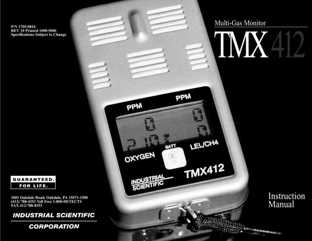
3 Dear Valued Customer: Thank you for buying and using Industrial Scientific s Model TMX412 Multi-Gas Monitor. Your TMX412 can be relied upon for dependable service, day after day. It has been designed, manufactured, tested and proven under the most scrutinizing conditions possible. With the minimal care and maintenance described in this Instruction Manual, it will provide you with years of reliable monitoring. I am most concerned that you be pleased with the performance of your TMX412 in the months and years ahead. I urge you to call us with any questions or comments you may have. Often times a phone call and a question can save you hours of frustration. Please never hesitate to contact me at DETECTS ( ). All of us at Industrial Scientific appreciate the opportunity to serve you. Yours very truly, Kent D. McElhattan President & CEO Industrial Scientific Corporation 1
4 TMX412 Multi-Gas Monitor 2 TABLE OF CONTENTS 1. WARNINGS AND CAUTIONARY STATEMENTS 3 2. UNPACKING THE INSTRUMENT 4 3. TMX412 FEATURES 4 4. INSTRUMENT OPERATION Charging the Battery Turning the TMX412 On and Off Display Backlight TMX412 Operating Modes Reading Sensor Configuration Zero Peak Peak Clear Date Cal Date Log Time TWA STEL Hygiene Reset TMX412 Alarm Indicators Low Alarm High Alarm Over-Range Indication Combustible Gas Over-Range Low Battery Warning Battery Failure Fault Indication 12 CALIBRATING THE TMX CHANGING INSTRUMENT SETTINGS Setspan Alarms Battery Code 18 HYGIENE FUNCTIONS Definition of Terms Data Log Period Logging Session Real Time Clock Log Time Clock Calendar TWA STEL Principles of Operation Resetting the Hygiene Functions 19 MAINTENANCE Cleaning Changing the Battery Opening the Instrument for Service Replacing Water Barriers Installing or Changing Sensors Toxic Sensor Removal Combustible Sensor Removal Oxygen Sensor Removal Instrument Reassembly After Service REPLACEMENT PARTS SPECIFICATIONS DEFAULT ALARM SETTINGS TMX412 OPTIONS & ORDERING INFORMATION WARRANTY WARNINGS AND CAUTIONARY STATEMENTS Failure to observe certain procedures or conditions may impair the performance of the instrument. For maximum safety and performance while using the instrument, please read and understand the procedures and conditions outlined below.! Oxygen deficient atmospheres may cause readings of combustible gas lower than actual concentrations.! Oxygen enriched atmospheres may cause readings of combustible gas higher than actual concentrations.! Verify calibration of the combustible gas sensor after use where the combustible gas content causes the instrument to latch in the OVER-RANGE alarm condition.! Silicone compound vapors may cause desensitization of the combustible gas sensor and may cause readings of combustible gas to be lower than actual gas concentrations. If the instrument has been used in an area where silicone vapors were previously present, always verify the instrument s calibration before next use to ensure accurate measurements.! Sensor aperture areas and water barriers must be kept clean. Obstruction of the sensor aperture areas and/or contamination of the water barriers may cause readings to be lower than actual gas concentrations.! Sudden changes in atmospheric pressure may cause temporary fluctuations in the oxygen reading.! Recharge battery only in a non-hazardous location.! Use the RS-232 port only in a non-hazardous location.! Instrument is tested for intrinsic safety in explosive gas/air (21% oxygen) mixtures only. CAUTION: High Over-Range (+OR) combustible! gas readings may indicate an explosive concentration of combustible gas. 3
5 2. UNPACKING THE INSTRUMENT The shipping box should contain the following items. Account for each item before discarding the box. QUANTITY PART NUMBER DESCRIPTION TMX412 Multi-Gas Monitor or TMX412 Multi-Gas Monitor (Australian Version) TMX412 Instruction Manual Keypad Overlay Leather Carrying Case Maintenance Tool or Maintenance Tool (Australian Version) Calibration Cup Teflon Lined Tygon Tubing After unpacking, if any listed item is missing, contact either your local distributor of Industrial Scientific products, or call Industrial Scientific Corporation at DETECTS ( ) in the United States and Canada, or TMX412 FEATURES The Industrial Scientific TMX412 Multi-Gas Monitor may be configured to continuously monitor one, two, three or four gases in any combination of the following: Oxygen Combustible gases (%LEL) or methane (% by volume CH 4 ). User selects %LEL or %CH 4 prior to calibration. Any two of the following toxic gases: Carbon Monoxide Hydrogen Sulfide Sulfur Dioxide Chlorine Nitrogen Dioxide Chlorine Dioxide The TMX412 automatically recognizes and displays the sensor configuration when switched on. One-Button microprocessor controlled calibration. Illuminated display for viewing in low light conditions. Round-the-clock monitoring capability using the interchangeable nickel-cadmium rechargeable, disposable lithium, or disposable alkaline battery packs. Plug-in sensors that can be changed or replaced without special tools or soldering equipment. Audible and visual alarm indicators. Optional external audible or vibrating alarms. High and low alarms for combustible and toxic gases; enrichment and depletion alarms for oxygen. User selectable access code for security of calibration and alarm settings. Combustible gas OVER-RANGE protection. PEAK reading mode. Press and hold power switch to prevent accidental turn on or turn off. Hygiene/Data Log option that can be installed by the factory or the customer, to provide short term exposure limit (STEL) and time-weighted average (TWA) readings with data logging. The TMX412 is classified as intrinsically safe by the following agencies: - Underwriters laboratories (UL). - Canadian Standards Association (CSA). Canadian Standards Association has assessed only the combustible gas portion of this instrument for performance. - Mine Safety and Health Administration (MSHA). - Workcover Authority, NSW, Australia. - Department of Mineral Resource, NSW, Australia. 4 5
6 Toxic Sensor Port 1 Toxic Sensor Port 2 Oxygen Sensor Port Combustible Gas Sensor Port LED Alarm Indicators Toxic Sensor Display Oxygen Sensor Display Battery Condition Display E/Backlight Key * OXYGEN INDUSTRIAL SCIENTIFIC BATT E 0 0 LEL/CH4 TMX412 Combustible Sensor Display Unmarked keys allow alarm and calibration setting changes using removable overlay Mode (M) Switch RS-232 Jack for Hygiene Downloading Buzzer External Alarm Jack Charging Jack Battery Cover Fasteners Stainless Steel Case for RFI Protection Note: Australian models have recessed hex battery cover fasteners as shown Battery Cover 6 7
7 4. INSTRUMENT OPERATION 4.1 CHARGING THE BATTERY CAUTION: If the TMX412 is using the nickelcadmium battery pack, fully charge! the battery pack prior to use. NOTE: The TMX412 must be turned off while charging the battery. A single unit compact trickle (10 hour) charger is available for charging the battery in the instrument. In addition to the compact charger, Industrial Scientific offers a full line of chargers with dual rate (4.5 hour) or trickle charging systems in single, dual or four unit configurations. All chargers are capable of charging the battery in or out of the instrument. All dual rate chargers offer the user selectable discharge-before-charge feature to prevent battery memory conditions caused by some repetitive use patterns. Refer to Section 12, Options and Ordering Information, for a complete listing of available chargers. When charging the battery pack in the instrument, be certain that the instrument is turned off and place it on the battery charger. To charge the battery pack out of the instrument, remove the pack and place it on the charger. A fully charged battery pack will operate a four-gas configured TMX412 for up to 10 hours. When the instrument is in the normal viewing mode, an eightsegment battery status indicator continuously displays the battery condition. Each segment represents approximately one hour of operating time. When the battery is fully discharged, the display reads BATTERY FAIL and the instrument emits a short beep once a second. Turn off the instrument and recharge the battery pack when BATTERY FAIL appears. 4.2 TURNING THE TMX412 ON AND OFF Press and hold the MODE switch. The display will read HOLD and the instrument sounds a short beep approximately once a second. Continue holding the MODE switch until the RELEASE screen appears. (Stop here if turning the instrument off.) After the instrument is turned ON, the following startup screens will be displayed: SENSOR CONFIGURATION. The type of sensors installed in the instrument will be displayed. WARM-UP TIMER. The display will indicate the number of seconds remaining until the instrument begins normal operation. After the warm-up sequence has been completed, the TMX412 will enter the normal operating mode and will be continuously monitoring all calibrated sensors. 4.3 DISPLAY BACKLIGHT The display backlight is automatically switched on when the TMX412 is in an alarm condition. To manually activate the backlight when needed, press and release the (E) key. The backlight will illuminate the display for approximately 15 seconds. 4.4 TMX412 OPERATING MODES The TMX412 offers different operating modes for accessing various instrument features. To scroll through the operating modes, press and release the MODE switch The operating modes will be accessed in the following sequence: READING This is the normal operating mode. The current reading of all sensors is displayed along with the graphical battery charge indicator SENSOR CONFIGURATION This mode will display the type of sensor in the position in which it is installed in the instrument. HOLD RELEASE CO H2S 02 LEL 10 O * 0 CO H2S 02 LEL 8 9
8 ZERO 65P K 12 PK CLEAR DATE 5/21 CALDATE 5/13 RT06:45 LT01: TWA 0 0 STEL HYGIENE ZERO This mode allows the user to zero the instrument and calibrate all installed sensors. Refer to section 5, Calibrating the TMX412, for instruction on the use of the instrument s automatic zero and calibration functions PEAK This mode will display the highest level of toxic and combustible gas and the lowest level of oxygen measured since the peak readings were last cleared. Press the MODE switch to access the PEAK reading screen PEAK CLEAR This mode will clear all stored peak readings from the TMX412. Press enter (E) to clear the peak readings. The display will return to the PEAK mode and indicate that the peak readings have been reset. If the TMX412 hygiene option is installed in the instrument, the following operating modes may also be accessed. See Section 7, Hygiene Functions, for further instructions DATE This screen allows the user to see the current date (month/day) set in the instrument CAL DATE This mode allows the user to see the date the unit was last calibrated LOG TIME This mode allows the user to view the current time set in the instrument (RT) and the length of time that data has been logged in the current session (LT) TWA (Time-Weighted Average) This mode displays the current time-weighted average exposure of the toxic sensors installed in the instrument STEL (Short Term Exposure Limit) This mode displays the short term average exposure of the toxic sensors installed in the instrument HYGIENE RESET This mode allows the user to reset the hygiene session and the STEL and TWA exposure values. 4.5 TMX412 ALARM INDICATORS LOW ALARM When a monitored gas concentration reaches the low level alarm setpoint, the instrument emits a short beep approximately every 1.2 seconds. The four red alarm LEDs and backlight will flash simultaneously. The displayed value of the alarming gas will flash. If the hygiene option is installed, the TWA alarm will mimic the low alarm indicator and the TWA display value in alarm will flash HIGH ALARM When a monitored gas concentration reaches the high alarm level setpoint, the instrument emits a continuous dual tone alarm. As with the low alarm condition, the four red alarm LEDs and backlight will flash simultaneously with the displayed gas value. If the hygiene option is installed, the STEL alarm will mimic the high alarm indicator and the STEL display value in alarm will flash. NOTE: The TMX412 uses the continuous high alarm tone for both low (depletion) and high (enrichment) oxygen alarm conditions OVER-RANGE INDICATION An over-range condition occurs when a sensor reading exceeds the upper limit of the instrument display range. Over-Range is indicated by +OR in the appropriate sensor display location. With the exception of combustible gas over-range, all over-range conditions will clear automatically when the gas concentration has decreased to a level within the display range of the instrument COMBUSTIBLE GAS OVER-RANGE When the TMX412 detects combustible gases in excess of 100% of LEL or 5% CH 4 by volume, a high alarm condition is latched and +OR is displayed in place of the combustible gas reading. Power is removed from the combustible gas sensor to prevent damage due to the high level of combustible gas. O * +OR 11
9 BATTERY FAIL 12 To clear the combustible gas over-range alarm: Exit the hazardous area immediately. Press the enter (E) key in clean air. NOTE: When the enter (E) key is pressed, the combustible gas level must be less than 100% of LEL or 5% CH 4 to clear the combustible gas over-range condition LOW BATTERY WARNING When approximately 1 hour of instrument operation energy remains in the battery, the instrument emits a short beep every 15 seconds. In addition, the battery indicator will be replaced by a flashing B on the display. NOTE: The length of warning time will increase when there is no combustible gas sensor installed in the instrument BATTERY FAILURE When the battery has insufficient charge to operate the instrument, BATTERY FAIL is displayed. The instrument stops monitoring and emits a short beep once every second. When BATTERY FAIL appears, turn off the instrument immediately. Recharge or replace the battery FAULT INDICATION The TMX412 will emit a short beep approximately once a second if a newly installed sensor does not agree with the valid sensor type for that position when the instrument is turned on. The corresponding display position will be blank. This fault indication occurs when a toxic or combustible sensor becomes disconnected or a combustible fault is detected during normal operation. Sensor types become valid only after a successful calibration has been completed. 5. CALIBRATING THE TMX412 The TMX412 is a potential life saving device. Recognizing this fact, Industrial Scientific Corporation recommends that a functional ( bump ) test be performed on every instrument prior to each days use. A functional test is defined as a brief exposure of the monitor to a known concentration of gas(es) for the purpose of verifying sensor and alarm operation and is not intended to be a measure of the accuracy of the instrument. Industrial Scientific further recommends that a full instrument be performed using a certified concentration(s) of calibration gas(es) monthly to ensure maximum accuracy. If an instrument fails to operate properly following any functional bump test, a full instrument calibration should be performed prior to use. Calibration will be most accurate when the instrument has been in a stable temperature environment for at least one hour prior to calibrating. NOTE: Instrument zero and oxygen span calibration should be performed in clean air containing 20.95% (21%) oxygen. If you are measuring a known combustible gas, use a known %LEL concentration of that gas for span calibration. For general combustible gas measurement, Industrial Scientific Corporation recommends calibrating to pentane in the 15-50% LEL range. The measured LEL concentration of gases other than the calibration gas may not correspond on a one-to-one basis with the monitor reading. Calibration gas flow rate should be between 0.5 and 1.0 liters per minute. Apply CL 2, at a 1.0 liter per minute flow rate. Always use teflon or teflon lined tubing when calibrating Cl 2 or NO 2 sensors. The TMX412 utilizes a one-button calibration system. When using multi-component gas cylinders, a full instrument span calibration can be performed in a single step. Multi-component calibration gas cylinders are available for combustible gas/carbon monoxide/hydrogen sulfide configurations. To calibrate the TMX412: From the normal READING mode, press the MODE switch to access the ZERO operating mode. Press the (E) key to start the instrument zeroing process. The instrument display will indicate ZEROING. When zeroing is complete the instrument display will indicate O2 CAL and will show the current full span value of the oxygen sensor. The oxygen sensor will be spanned to 21.0 in approximately 30 seconds. Oxygen calibration may be aborted at this time by pressing the MODE switch. NOTE: Zeroing the instrument in clean air is preferred, provided that there is no trace of toxic or combustible gas that would cause the instrument to respond. If the air purity is uncertain, use a cylinder of zero grade air to zero the instrument and span the oxygen sensor. ZERO ZEROING CAL 13
10 GO CAL 25 LEL APPLY 14 At the completion of the oxygen sensor span operation the instrument will emit a short beep and the display will indicate GO CAL and the message (E) to CAL will scroll across the bottom of the display. Press (E) to continue calibrating the remaining sensors. Ignoring this message will result in the instrument returning to the normal operating mode in approximately eight seconds. When the GO CAL prompt has been acknowledged, the instrument will display the first sensor to be calibrated along with the span gas value. The message APPLY CAL GAS will scroll across the bottom of the display. NOTE: APPLY CAL GAS means connect the calibration cup to the appropriate calibration gas cylinder. Place the calibration cup on the instrument as shown. Turn on gas supply. Apply the appropriate concentration of calibration gas. The instrument will wait for three minutes to sense that calibration gas has been applied before aborting and failing calibration. When the instrument senses a concentration greater than 50% of the span gas setting the display will indicate the current full span value for that sensor. The message CAL IN PROCESS will scroll across the bottom of the display. When calibration of the sensor has been successfully completed, the instrument will automatically step to the next sensor to be calibrated and the preceding step will be repeated. When all sensors have been calibrated successfully the instrument will emit a short beep. The sensor configuration will be shown on the display and sensor identifiers will flash to warn of marginal calibration. Marginal calibration will occur if the sensor full span value is less than 70% of the applied gas concentration. A marginal sensor calibration may be an early warning sign that the sensor will soon need to be replaced. NOTE: If the sensor full span value is less than 50% of the applied gas value, the sensor will fail calibration and the instrument will immediately return to the real time READING mode. When failed calibration or low sensitivity is indicated, verify that the calibration cylinder has not emptied or that the cylinder expiration date has not passed. After displaying the sensor configuration, the instrument will automatically return to the real time READING mode. 6. CHANGING INSTRUMENT SETTINGS Instrument settings, including alarm values, calibration gas concentrations and security code, may only be accessed and changed during the instrument startup sequence. A keypad overlay is supplied to reveal the location of the hidden keys used for changing instrument settings. Remove the overlay from the protective backing and place it over the instrument faceplate. The clear portion of the overlay will cling to the display window of the faceplate and may be reused. To access the instrument menus: Turn the TMX412 off and back on again. When the display shows the warm up timer, press the plus (+) and minus (-) keys simultaneously. If the instrument security code has been set to a value other than 0, the CODE screen will be displayed along with the scrolling prompt (+) OR (-) TO SET (E) TO ENTER. Use the (+) and (-) keys to input the correct security code value and press (E). When the correct code has been entered successfully, the instrument will immediately enter the settings mode. The settings mode consists of three main functions in the following order: SETSPAN ALARMS BATTERY CODE The scrolling prompt, (+) FOR NEXT (E) TO SELECT appears on each screen. Press the (+) to step through the list and (E) to select any of the main functions. Pressing the MODE switch at any one of the main function headings will cause the instrument to return to the normal operating mode. 6.1 SETSPAN The SETSPAN function allows the user to set the combustible sensor monitoring range to either LEL or CH 4 and to set the calibration gas values for the combustible and toxic sensors. Press (E) to enter the SETSPAN function. The display will show LEL along with the prompt (+) TO CHANGE * OXYGEN INDUSTRIAL SCIENTIFIC BATT E 0 0 LEL/CH4 TMX412 SETSPAN 15
11 LEL 25 LEL Press (+) to toggle between LEL and CH 4 combustible sensor span ranges. Press MODE to enter the span gas values for all sensors. The display will show the first span value, eg. 25 LEL, along with the prompt (+) FOR NEXT (E) TO SELECT. Press (E) to select the value you wish to change. The display will flash the current span value and will scroll the prompt (+) or (-) TO SET (E) TO ENTER. Press the (+) and (-) minus keys to set the desired span value and (E) to enter the value into memory. Once the value has been entered into memory, it will become the standard span gas value used during instrument calibration. Press the MODE switch to return to the SETSPAN function. Press (E) to enter the instantaneous alarms function. The display will show the first alarm to be set along with the scrolling prompt (+) FOR NEXT (E) TO SELECT. The alarm type will be indicated on the display as either high (H) or low (L). Press (E) to select the desired alarm to be changed. The display will flash the current alarm value along with the prompt (+) OR (-) TO SET (E) TO SELECT. Press the (+) and (-) keys to set the desired alarm value and (E) to enter the value into memory. Press MODE to return to the INSTANT function. Press (+) to step to the TWA and STEL alarm functions. The TWA and STEL alarm values are set as previously described. 6.3 BATTERY The BATTERY option allows the user to select the type of battery installed in the unit. The setting configures the battery indicator to accurately display the discharge rate of the selected battery type. Change the battery setting as follows: 1. From Setup, access the BATTERY option by pressing the hidden + key until BATTERY appears on the display and then press the E key. 2. Press the hidden + key to toggle between battery types. The display will show NCD/LI for Ni-Cad or lithium batteries and ALKALNE for alkaline batteries. 3. Press the E key to select battery type shown. 4. Press the Mode key twice to return to Reading Mode for normal operation of the instrument. 10L LEL LATCH ALARMS LATCH OFF INSTANT 6.2 ALARMS The ALARMS function allows you to set the values for the HI and LOW alarms for each installed sensor. Default alarm settings for each gas are listed in Section 11. If the hygiene/datalogging option is installed, you will also be able to set the STEL and TWA alarm values. Press (+) to step from the SETSPAN function to the ALARMS function. Press (E) to enter the ALARMS function. The LATCH function will lock the alarm indicators on when a monitored gas concentration reaches the high alarm setpoint. The alarm will reset after the gas concentration has fallen below the alarm setpoint and the user has pressed the (E) key. The display will indicate LATCH along with the scrolling prompt (+) FOR NEXT (E) to SELECT. Press (E) to select the LATCH function. The display will indicate LATCH along with the prompt (+) FOR NEXT (E) TO SELECT. Press (E) to set the TMX412 high alarm latch as ON or OFF. Press MODE to return to the LATCH screen. Press (+) to step to the INSTANT function and set instantaneous alarm values. The display will indicate INSTANT along with the scrolling prompt (+) FOR NEXT (E) TO SELECT. BATTERY NCD/LI 16 17
12 CODE CODE CODE The CODE function allows the user to select a security code to protect calibration and all instrument alarm settings. When the code is set to any value other than 0, the user will be prompted to enter the proper code prior to entering the settings or calibration modes. Press (+) to step from the ALARMS function to the CODE function. Press (E) to enter the code function. The display will show the current code setting along with the scrolling prompt (+) OR (-) TO SET (E) TO ENTER. Press the (+) and (-) keys to set the code to any value between 0 and 999, and (E) to enter the value into memory. Press MODE to return to the CODE function. 7. HYGIENE FUNCTIONS 7.1 DEFINITION OF TERMS DATA LOG Record of measured gas concentrations, including time and date, stored in the instruments electronic memory PERIOD The logging time that begins when the instrument is turned on and begins normal operation and lasting until the instrument is turned off LOGGING SESSION One or more periods of normal instrument operation between hygiene function resets REAL TIME CLOCK A clock function in the instrument that maintains the current time LOG TIME CLOCK A clock function in the instrument that monitors the length of time logged during a session CALENDAR A part of the real time clock function that maintains the current date TWA (TIME-WEIGHTED AVERAGE) The accumulated gas exposure averaged over a predetermined time, typically eight hours STEL (SHORT TERM EXPOSURE LIMIT) The accumulated gas exposure value averaged for the proceeding fifteen minutes. 7.2 PRINCIPLES OF OPERATION If the TMX412 is equipped with the hygiene option, all instantaneous readings of valid installed sensors are sent to the hygiene module. Once every minute, the readings are averaged, the average values are saved to the data log and the TWA and STEL values are calculated for the toxic sensors. The TWA and STEL values are then tested for possible alarm conditions. The default time base for calculating TWA values is eight hours. However, the time base may be changed to any integer value in the range of one to 40 hours using the optional TMX Hygiene Software and a personal computer. The 130,816 byte memory provides storage capacity for approximately 110 hours of logged data with four sensors installed. The data logging section of the instrument is always powered and a battery backup circuit protects from loss of data for up to 40 minutes during battery changes. NOTE: The instrument must be stored on a battery charger when not in use to prevent loss of data due to battery discharge. 7.3 RESETTING THE HYGIENE FUNCTIONS NOTE: If the data logging feature is to be used, ensure the correct date and time information is logged by checking/setting the Real Time Clock and Calendar using the optional TMX Hygiene Software. Press MODE repeatedly to step to the HYGIENE screen. Press (E) to reset the hygiene function and begin a new data logging session
13 RT06:45 LT00:00 RTOR:OR LT00:00 RTOR:OR LT0R:0R 8. MAINTENANCE The instrument display will return to the LOG TIME mode and the display will indicate that the log time (LT) will be reset to 00:00. The TWA and STEL values for all toxic sensors will also be reset to zero. If there is insufficient memory to log approximately 12 hours of data when the hygiene function is reset, the real time clock value will be displayed as RTOR:OR. When the data memory is full, both the real time and log time will be displayed as OR:OR. The data memory may be cleared when full by performing a hygiene reset as described above. All currently stored data will be overwritten. The stored data may be downloaded using the TMX hygiene software. 8.1 CLEANING Wipe the outside of the instrument with a soft, clean cloth. Never use solvents or cleaning solutions of any type. 8.2 CHANGING THE BATTERY To change the TMX412 battery pack: Hold the instrument with battery cover facing up. Turn the battery cover latches counter-clockwise one quarter of a turn using the maintenance tool supplied to release the cover. Gently press down on the bottom of the battery pack to release the top contacts. Grasp the battery along the edges and lift out. Insert replacement battery, and replace battery cover. Turn the latches one quarter turn in the clockwise direction to secure the battery cover.! WARNING: When changing lithium battery cells, replace the cells within the lithium battery pack in a nonhazardous location. Replace the lithium cells with three Duracel DL123A or three Panasonic CR123A or three Sanyo CR123A 3.0 volt lithium battery cells only. Use of another battery may present a risk of fire or explosion. WARNING: Lithium battery cells may explode if! mistreated. Do not recharge, disassemble, or dispose of in fire. Do not charge the replaceable lithium battery pack either while it is installed in, or removed from the instrument. WARNING: The replaceable lithium! battery pack is not approved for use in applications or areas requiring MSHA approval. WARNING: Australian TMX412, p/n , is to be used with Nicad battery pack p/n only.! 8.3 OPENING THE INSTRUMENT FOR SERVICE Remove the battery cover and battery. Remove the three screws that hold the instrument case halves together. Grasp the bottom half of the instrument with one hand. Using the other hand, lift the top until it clears the sensors. Then place it face down next to the instrument. Use care not to damage the flex cable connecting the case top to the main circuit board. 8.4 REPLACING WATER BARRIERS When the sensor water barrier becomes clogged or damaged, it is necessary to replace them. To replace the watter barrier: Lift the water barrier and filter screen from inside the top case half and remove. Place the new water barrier and filter screen in the top case half. 8.5 INSTALLING OR CHANGING SENSORS Open the instrument as described. Carefully remove the sensor shroud by lifting it straight up
14 Shorting Wire NOTE: The TMX412 must be calibrated whenever a sensor is installed or replaced. All installed sensor types are shown on the Sensor Configuration screen during instrument start-up. However, a fault condition will be indicated if the instrument has not been calibrated for any of the installed sensor types. When a new oxygen sensor is installed, allow 15 minutes for it to stabilize before attempting calibration. If the toxic sensor is replaced with a different type or the combustible sensor is reconfigured, the alarm settings must be changed to reflect the appropriate alarm settings for the sensor installed TOXIC SENSOR REMOVAL/ REPLACEMENT To remove the toxic sensor, grasp the sensor and lift it straight up. Use care to avoid bending the sensor pins. WARNING: When removing the toxic sensor for! storage, connect a shorting wire to the two pins as shown. New sensors are shipped with a shorting wire attached. Remove the shorting wire from the new sensor. Immediately install the sensor in the instrument. Never apply pressure to the area inside of the black O-Ring seal at the top of the sensor COMBUSTIBLE SENSOR REMOVAL/ REPLACEMENT To remove the combustible sensor, grasp the sensor and lift it straight up. When installing the combustible sensor, align the notch on the sensor body with the polarizing pin on the sensor board OXYGEN SENSOR REMOVAL/ REPLACEMENT Remove the two mounting screws and nylon washers using the maintenance tool or small Phillips screwdriver. Bend the two mounting tabs out as shown before installing the new sensor. 8.6 INSTRUMENT REASSEMBLY AFTER SERVICE Reassemble the instrument by aligning the two posts with the corresponding openings in the circuit board. Gently fit the instrument case halves together, making certain that the gasket is properly seated, and the flex cable is not pinched between the buzzer and the instrument case top. Replace and tighten the three retaining screws until they are firmly seated. Do not overtighten. Replace the battery and battery cover. Toxic Sensor 1 Toxic Sensor 2 Oxygen Sensor OXYGEN LEL Combustible Gas Sensor Polarizing Pin Easy-to read Liquid Crystal Display 22 23
15 24 25
16 26 9. REPLACEMENT PARTS The following items numbers refer to the exploded view drawing on pages 24 and 25. ITEM PART NUMBER DESCRIPTION (QTY) Display P.C. Board Assembly (1) or Display P.C. Board Assembly (1) (Australian Version Only) Alarm P.C. Board Assembly (1) or Alarm P.C. Board Assembly (1) (Australian Version Only) Main P.C. Board Assembly (1) Sensor P.C. Board Assembly (1) Case Top Assembly (1) Case Bottom Assembly (1) Nicad Battery Pack (1) or Nicad Battery Pack (1) (Australian Version Only) Battery Case Cover (1) Keypad/Faceplate (1) Sensor Shroud (1) Alarm Bezel (1) 12 Sensor Barrier/Seal (1), consists of: Sensor Membrane Sensor Gasket Alarm Bezel Gasket (1) Mode Button Seal (1) Mode Button (1) Circuit Board Spacer (2) Receptacle, 3 Contact (1) Charging Jack (1) Dzus Stud (2) or Dzus Stud (2) (Australian Version Only) Stud Seal (2) Battery Cover Gasket (1) Conductor Cable (1) Instrument Strap (1) Split D-Ring (1) RFI Case Gasket (1) External Alarm Jack (1) Hole plug (1) RFI Screen (1) Screw, FHCR 4-40 x.47 SST (2) Screw, PHCR 4-40 x.25 SST (2) Screw, FHCR 4-40 x.38 SST (3) Conductive Tape, RF Screen (1) Circuit Board Support (2) Battery Spacer (1) Data Port Plug (1) Mode Switch Spacer Main Board Insulator 10. SPECIFICATIONS CASE: Stainless Steel DIMENSIONS: 4.75 L x 2.75 W x 2 H (121 X 70 X 51 mm) WEIGHT: SENSORS: 26 ounces (738 grams) MEASURING RANGE: LEL (Combustible Gases) 0 to 100% in 1% increments Combustible Gases and Methane- Catalytic Oxygen and Toxic Gases- Electrochemical CH 4 (Methane) 0 to 5% of volume in 0.1% increments O 2 (Oxygen) 0 to 30% of volume in 0.1% increments CO (Carbon Monoxide) 0 to 999 PPM (parts per million) in 1 PPM increments H 2 S (Hydrogen Sulfide) 0 to 999 PPM (parts per million) in 1 PPM increments SO 2 (Sulfur Dioxide) 0.2 to 99.9 PPM (parts per million) in 0.1 PPM increments NO 2 (Nitrogen Dioxide) 0.2 to 99.9 PPM (parts per million) in 0.1 PPM increments C1 2 (Chlorine) 0.2 to 99.9 PPM (parts per million) in 0.1 PPM increments C10 2 (Chlorine Dioxide) 0 to 99.9 PPM (parts per million) in 0.1 PPM increments POWER SOURCE: Rechargeable, replaceable nickel-cadmium battery pack, replaceable cell lithium battery pack or 9-volt alkaline battery packs BATTERY LIFE: READOUT: With Combustible Sensor 10 hours (Nicad) Without Combustible Sensor 10 days (Nicad) Alpha-Numeric Liquid Crystal Display TEMPERATURE RANGE: Continuous Operation -20ºC to 50ºC (-4ºF to 122ºF) 27
17 28 Intermittent Operation (Up to 8 hours) Carbon Monoxide -20ºC to 55ºC (-4ºF to 131ºF) Chlorine -20ºC to 55ºC (-4ºF to 131ºF) Hydrogen Sulfide -40ºC to 50ºC (-40ºF to 122ºF) Nitrogen Dioxide -20ºC to 55ºC (-4ºF to 131ºF) Oxygen -20ºC to 55ºC (-4ºF to 131ºF) Sulfur Dioxide -20ºC to 55ºC (-4ºF to 131ºF) Chlorine Dioxide -20ºC to 50ºC (-4ºF to 122ºF) HUMIDITY RANGE: (Non Condensing) STORAGE TEMPERATURE: 15% to 90% RH (Continuous Operation) 0% to 99% RH (Intermittent Operation) 0ºC to 20ºC (32ºF to 68ºF) 11. DEFAULT ALARM SETTINGS GAS LOW ALARM HIGH ALARM O % 23.5% LEL 10% 20% CH 4 1.0% 1.5% CO 35 PPM 70 PPM H 2 S 10 PPM 20 PPM SO PM 4.0 PPM NO PPM 6.0 PPM Cl PPM 1.0 PPM ClO PPM 1.0 PPM 12. TMX412 OPTIONS & ORDERING INFORMATION PART NUMBER DESCRIPTION (QTY) Combustible Sensor Oxygen Sensor Hydrogen Sulfide Sensor Carbon Monoxide Sensor Chlorine Sensor Nitrogen Dioxide Sensor Sulfur Dioxide Sensor Replaceable 9-volt Alkaline Battery Pack (includes 2) VAC Compact Economy Charger VAC Two Unit Compact Charger VAC Two Unit Dual Rate Charger VAC Four Unit Dual Rate Charger VAC Four Unit Dual Rate Charger VAC Four Unit Dual Rate Charger VAC Two Unit Compact Charger (Australian Version) VAC Two Unit Compact Charger VAC One Unit Dual Rate Charger VDC One Unit Compact Charger VDC Two Unit Dual Rate Charger SP402 Sampling Pump with hose (UL) * SP402 Sampling Pump with hose (CSA) Constant Flow Hand Pump with Hose Stainless Steel Extendible Probe - 6ft Polycarbonate Probe Rechargeable Nicad Battery Pack Rechargeable Nicad Battery Pack (Australian Version) Chlorine Dioxide Sensor Replaceable Lithium Battery Pack (includes 3) Replacement Lithium Battery Cell Leather Carrying Case for TMX Leather Combination Carrying Case for SP402/TMX Leather Handle for Carrying Case Nylon Carrying Case for TMX Nylon Combination Carrying Case for TMX412/SP External Audible/Visual Alarm (103 db) * Vibrating Alarm Cylinder Cal. Gas, H 2 S, CO, Pentane, Oxygen Cylinder, Cal. Gas, Carbon Monoxide, Pentane and Oxygen Cylinder, Cal. Gas, Carbon Monoxide, Methane and Oxygen Cylinder, Cal. Gas, Zero Air Cylinder, Cal. Gas, 5 PPM Sulfur Dioxide Cylinder, Cal. Gas, 10 PPM Chlorine Cylinder, Cal. Gas, 5 PPM Nitrogen Dioxide Flow Regulator with Pressure Gauge, for all cylinders except Ammonia Teflon Lined Tygon Tubing (24 ) Calibration Cup * Denotes CSA approved accessory 29
18 13. WARRANTY Industrial Scientific portable gas monitoring instruments are warranted to be free from defects in material and workmanship for as long as the instrument is in service. The above warranty does not include sensors, battery packs, internal pumps or filters, all of which are warranted to be free from defects in material and workmanship for eighteen months from the date of shipment, or one year from the date of first use, whichever occurs first, except where otherwise stated in writing in Industrial Scientific literature accompanying the product. All other Industrial Scientific products are warranted to be free from defects in material and workmanship for a period of eighteen (18) months from the date of shipment, or one (1) year from the date of first use, whichever occurs first, except where otherwise stated in writing in Industrial Scientific literature accompanying the product. LIMITATION OF LIABILITY INDUSTRIAL SCIENTIFIC MAKES NO OTHER WARRANTIES, EITHER EXED OR IMPLIED, INCLUDING BUT NOT LIMITED TO THE WARRANTIES OF MERCHANTABILITY OR FITNESS FOR PARTICULAR PURPOSE. SHOULD THE PRODUCT FAIL TO CONFORM TO THE ABOVE WARRANTY, BUYER S ONLY REMEDY AND INDUSTRIAL SCIENTIFIC S ONLY OBLIGATION SHALL BE, AT INDUSTRIAL SCIENTIFIC S SOLE OPTION, REPLACEMENT OR REPAIR OF SUCH NON-CONFORMING GOODS OR REFUND OF THE ORIGINAL PURCHASE PRICE OF THE NON-CONFORMING GOODS. IN NO EVENT WILL INDUSTRIAL SCIENTIFIC BE LIABLE FOR ANY OTHER SPECIAL, INCIDENTAL OR CONSEQUENTIAL DAMAGES, INCLUDING LOSS OF PROFIT OR LOSS OF USE, ARISING OUT OF THE SALE, MANUFACTURE OR USE OF ANY PRODUCTS SOLD HEREUNDER WHETHER SUCH CLAIM IS PLEADED IN CONTRACT OR IN TORT, INCLUDING STRICT LIABILITY IN TORT. It shall be an express condition to Industrial Scientific s warranty that all products be carefully inspected for damage by Buyer upon receipt, be properly calibrated for Buyer s particular use, and be used, repaired, and maintained in strict accordance with the instructions set forth in Industrial Scientific s product literature. Repair or maintenance by non-qualified personnel will invalidate the warranty, as will the use of non-approved consumables or spare parts. As with any other sophisticated product, it is essential and a condition of Industrial Scientific s warranty that all personnel using the products be fully acquainted with their use, capabilities and limitations as set forth in the applicable product literature. Buyer acknowledges that it alone has determined the intended purpose and suitability of the goods purchased. It is expressly agreed by the parties that any technical or other advice given by Industrial Scientific with respect to the use of the goods or services is given without charge and at Buyer s risk; therefore, Industrial Scientific assumes no obligations or liability for the advice given or results obtained
TMX 412. Instruction Manual. Multi-Gas Monitor. P/N REV 11 Printed Specifications Subject to Change
 P/N 1705-0816 REV 11 Printed 0228 2010 Specifications Subject to Change Multi-Gas Monitor TMX 412 1001 Oakdale Road, Oakdale, PA 15071-1500 (412) 788-4353 Toll Free 1-800-DETECTS FAX 412-788-8353 Instruction
ATX620. Instruction Manual. Multi-Gas Monitor. P/N REV 02 Printed Specifications Subject to Change GUARANTEED. FOR LIFE.
 P/N 1706-3389 REV 02 Printed 0103-1000 Specifications Subject to Change Multi-Gas Monitor ATX620 GUARANTEED. FOR LIFE. 1001 Oakdale Road, Oakdale, PA 15071-1500 (412) 788-4353 Toll Free 1-800-DETECTS FAX
MDU 420. Instruction Manual. Dual Range Methane Monitor. P/N REV 0 Printed Specifications Subject to Change
 P/N 1705-2583 REV 0 Printed 0297-2000 Specifications Subject to Change Dual Range Methane Monitor MDU 420 GUARANTEED. FOR LIFE. 1001 Oakdale Road, Oakdale, PA 15071-1500 (412) 788-4353 Toll Free 1-800-DETECTS
T82. Instruction Manual. Single Gas Monitor GUARANTEED. FOR LIFE. P/N REV 0 PRINTED ,000 Specifications Subject to Change
 P/N 1709-4756 REV 0 PRINTED 0601-5,000 Specifications Subject to Change Single Gas Monitor T82 GUARANTEED. FOR LIFE. 1001 Oakdale Road, Oakdale, PA 15071-1500 (412) 788-4353 Toll Free 1-800-DETECTS FAX
Bacharach Bodyguard 4 User's Guide
 Bacharach Bodyguard 4 User's Guide This manual and the software described in it are copyrighted, with all rights reserved. Under the copyright laws, this manual or the software may not be copied, in whole
CO2 RESPONDER Portable Carbon Dioxide Detector QUICK REFERENCE GUIDE
 CO2 RESPONDER Portable Carbon Dioxide Detector QUICK REFERENCE GUIDE GasAlertMicro 5 IR from Refer to for more details. Manual provided on CD with unit at time of purchase 2 Table of Contents Getting Started.
Macurco Single-Gas XL Series Monitor, CM-1XL Carbon Monoxide (CO), HS-1XL Hydrogen Sulfide (H2S) User Instructions
, HS-1XL Hydrogen Sulfide (H2S) User Instructions") Macurco Single-Gas XL Series Monitor, CM-1XL Carbon Monoxide (CO), HS-1XL Hydrogen Sulfide (H2S) User Instructions Important: Keep these User Instructions for reference 2 TABLE OF CONTENTS GENERAL SAFETY
Macurco Single-Gas XL Series Monitor, CM-1XL Carbon Monoxide (CO), HS-1XL Hydrogen Sulfide (H2S) User Instructions Important: Keep these User Instructions for reference 2 TABLE OF CONTENTS GENERAL SAFETY
GasAlertMicroClip X3 Specifications
 GasAlertMicroClip X3 Specifications The instrument must satisfy the following: Physical Specifications Size (h x w x d) Physical size shall be no larger than 4.4 x 2.4 x 1.2 in. / 11.3 x 6.0 x 3.2 cm Weight
GasAlertMicro 5. 1, 2, 3, 4, and 5 Gas Detectors. Quick Reference Guide
 O 2, CO, H 2 S, PH 3, SO 2, Cl 2, NH 3, NO 2, HCN, ClO 2, O 3, VOC, and Combustibles 1, 2, 3, 4, and 5 Gas Detectors Quick Reference Guide Limited Warranty & Limitation of Liability BW Technologies Ltd.
Confined Space Monitoring. Leak Investigation. Functions 4. Bar Hole Sampling. Line Purge Testing. Actual Size GX-2012
 Confined Space Monitoring Leak Investigation 1 Functions 4 Bar Hole Sampling Line Purge Testing Actual Size GX-2012 3 Operating Modes Internal sample draw pump with 50 range Low flow alarm 3 bright visual
ALTAIR 5X Multigas Detector Product Specification
 ALTAIR 5X Multigas Detector Product Specification PHYSICAL CHARACTERISTICS Gas delivery Size, pumped unit without IR Size, pumped unit with IR Weight Handling Case material Environmental protection Display
SC-01 Operator s Manual
 SC-01 Operator s Manual Part Number: 71-0136RK Revision: D Released: 4/7/17 www.rkiinstruments.com WARNING Read and understand this instruction manual before operating instrument. Improper use of the gas
GasAlert. Introduction. WWarning. Table 1. GasAlert Models. Gas Monitored
 Introduction Table 1. GasAlert Models WWarning To ensure your personal safety, read Safety Information before you use the detector. The GasAlert gas detector ( the detector ) warns of hazardous gas at
EAGLE 2. 6 Channel Capacity. Inlet fitting. Loud buzzer (95dB) IrDA communication port Low flow shutoff and alarm Alarm LED s with wide visibility
 IrDA communication port Low flow shutoff and alarm Alarm LED s with wide visibility") EAGLE 2 Inlet fitting Loud buzzer (95dB) IrDA communication port Low flow shutoff and alarm Alarm LED s with wide visibility Internal / external hydrophobic filters Self healing polyurethane protective
EAGLE 2 Inlet fitting Loud buzzer (95dB) IrDA communication port Low flow shutoff and alarm Alarm LED s with wide visibility Internal / external hydrophobic filters Self healing polyurethane protective
IMR IX176 Portable Gas Detector User Manual
 IMR Portable Gas Detector User Manual Read this manual carefully before using this device. (727) 328-2818 / (800) RING-IMR Fax: (727) 328-2826 www.imrusa.com Ver. 1.0A4 CONTENTS SERVICE GUIDELINES... 3
QUICK REFERENCE GUIDE
 - 4GAS RESPONDER Confined Space Entry Portable Gas Detector QUICK REFERENCE GUIDE 4-GAS RESPONDER GasAlertMicro 5 from Refer to for more details. Manual provided on CD with unit at time of purchase 2 Table
Operate the Mutli-Gas Monitor PID
 TASK: Operate the Multi-Gas Monitor Learning Objective CONDITION: In a classroom environment, given a fully charged Multi-gas Monitor with the manufacturer operator s manual, all monitor components/accessories,
For the Safety of Your
 For the Safety of Your Team in Confined Spaces CSM 5000 Portable Multi-Gas Monitor H 2 S OX CO EX Do it Right Do it Safe Power/Select Button Used for turning the CSM 5000 ON and OFF, accessing download
5 Operating Modes GX Smallest 6 gas sample draw PID library of over 600 VOC s 2 Interchangable smart sensor slots
 5 Operating Modes GX-6000 Smallest 6 gas sample draw PID library of over 600 VOC s 2 Interchangable smart sensor slots CONFINED SPACE ENTRY Monitor LEL, O2, CO, and H2S Internal sample pump Pull samples
Safe Operation Manual. Honeywell IQ Force Gas Detector
 Safe Operation Manual Honeywell IQ Force Gas Detector Honeywell Analytics 800-663-4164 403-248-9226 Fax 403-575-3708 03JUN2012 P/N 50105843-047 Version 01 http://www.honeywell.com HONEYWELL IQ Force PERSONAL
5 Operating Modes GX Smallest 6 gas sample draw PID library of over 600 VOC s 2 Interchangable smart sensor slots
 5 Operating Modes GX-6000 Smallest 6 gas sample draw PID library of over 600 VOC s 2 Interchangable smart sensor slots GX-6000 5 Operating modes Normal Leak Check Inert Bar hole Snap Log Monitor up to
ToxiRAE II. PGM-1100 Series Personal Toxic Gas Monitor. User Manual
 ToxiRAE II PGM-1100 Series Personal Toxic Gas Monitor User Manual 045-4003-000, Rev C May 2007 - READ BEFORE OPERATING - This manual must be carefully read by all individuals who have or will have the
MiniCO, MiniH 2 S, MiniOX, MiniOX Remote, MiniCl 2. , and MiniClO 2. Responder Detectors Instruction Manual "! WARNING
 MiniCO, MiniH 2 S, MiniOX, MiniOX Remote, MiniCl 2 TM, and MiniClO 2 TM Responder Detectors Instruction Manual "! WARNING THIS MANUAL MUST BE CAREFULLY READ BY ALL INDIVIDUALS WHO HAVE OR WILL HAVE THE
Personal Single Gas Monitor. Activation Operation Troubleshooting
 Personal Single Gas Monitor Activation Operation Troubleshooting Part Number: 17123100 Revision: 3.0 Release Date: January 1, 2009 Table of Contents Warnings and Cautionary Statements... 3 Hardware Overview...
Reference Manual. MultiVision Gas Detector
 Reference Manual MultiVision Gas Detector Sperian Instrumentation 651 South Main Street Middletown, CT 06457 800 711-6776 860 344-1079 Fax 860 344 1068 24SEPT2008 P/N 13-230 Version 2.01 http://www.biosystems.com
Using the QRAE Plus personal multigas monitor
 Using the QRAE Plus personal multigas monitor Firmware v 1.10 QRAE Plus The Hazardous Environment Detection Company QRAE Plus features Turning on the QRAE Plus Recommended Daily Start-up Procedure User
GG-H2S HYDROGEN SULFIDE GAS SENSOR. Installation and Operation Manual
 GG-H2S HYDROGEN SULFIDE GAS SENSOR Installation and Operation Manual 2 GG-H2S Warning Use this product only in the manner described in this manual. If the equipment is used in a manner not specified by
GG-NO2 NITROGEN DIOXIDE GAS SENSOR. Installation and Operation Manual
 GG-NO2 NITROGEN DIOXIDE GAS SENSOR Installation and Operation Manual 2 GG-NO2 Warning Use this product only in the manner described in this manual. If the equipment is used in a manner not specified by
MGC Dock User s Manual
 Operator s Manual Contents Warnings Statements/Avertisseement... 3 READ FIRST BEFORE OPERATION... 3 Basic Operation... 4 Clip Dock Components... 4 LEDs... 4 Operation... 5 Turning the Clip Dock On and
GG-NH3 AMMONIA GAS SENSOR. Installation and Operation Manual
 GG-NH3 AMMONIA GAS SENSOR Installation and Operation Manual 2 GG-NH3 Warning Use this product only in the manner described in this manual. If the equipment is used in a manner not specified by Calibration
ToxiRAE II. PGM-1100 Series Personal Toxic Gas Monitor. User Manual
 ToxiRAE II PGM-1100 Series Personal Toxic Gas Monitor User Manual 045-4003-000, Revision B, March 2005 - READ BEFORE OPERATING - This manual must be carefully read by all individuals who have or will have
GASGUARD SO2 Sulfur Dioxide Sensor OPERATING & INSTALLATION MANUAL
 GASGUARD SO2 Sulfur Dioxide Sensor OPERATING & INSTALLATION MANUAL Operating and Installation Manual Warning Use this product only in the manner described in this manual. If the equipment is used in a
INSTRUCTION MANUAL MODEL GX-82A
 INSTRUCTION MANUAL MODEL GX-82A PORTABLE THREE GAS DETECTOR RKI Instruments, Inc. 1855 Whipple Road Hayward, CA 94544 Tel: 510-441-5656 Table of Contents INTRODUCTION 1 DESCRIPTION 2 COMPONENTS AND CONTROLS
Model GX-2001 Canadian Version Operator s Manual Part Number: RK Revision: 0 Released: 1/17/05
 Model GX-2001 Canadian Version Operator s Manual Part Number: 71-0103RK Revision: 0 Released: 1/17/05 RKI Instruments, Inc. 33248 Central Ave. Union City, CA 94587 Phone: 800-754-5165 Fax: 510-441-5650
OI-2400-DOCK Multi Gas Docking Station. Operation Manual trevision 2.2w
 OI-2400-DOCK Multi Gas Docking Station Operation Manual trevision 2.2w Table of Contents Introduction... 3 Warnings Statements/Avertisseement... 4 Basic Operation... 5 OI-2400-DOCK Components... 5 LEDs...
WATCHMAN MULTIGAS MONITOR
 WATCHMAN MULTIGAS MONITOR 08-02-39 FEATURES Continuously monitors combustible gases, oxygen, carbon monoxide and other toxic gases simultaneously; displays gas concentrations over large, easy-to-read digital
Instruction Manual Eagle Series
 Instruction Manual Eagle Series Portable Multi-Gas Detector Part Number: 71-0028RK Edition: Third Released: July 2001 RKI Instruments, Inc. 1855 Whipple Rd. Hayward, CA 94544 (510) 441-5656 Warranty RKI
Multi-gas Monitor. Product Manual Set-up Operation Service. Part Number: Version 12
 Multi-gas Monitor Product Manual Set-up Operation Service Part Number: 17152357-1 Version 12 1 Table of Contents COPYRIGHT NOTICE... 3 WARNINGS AND CAUTIONARY STATEMENTS... 3 General... 3 Personnel...
GASGUARD H2S EXP. Hydrogen Sulfide Sensor OPERATING & INSTALLATION MANUAL
 GASGUARD H2S EXP Hydrogen Sulfide Sensor OPERATING & INSTALLATION MANUAL Operating and Installation Manual Warning Use this product only in the manner described in this manual. If the equipment is used
Single Gas Detector. Quick Reference Guide
 Single Gas Detector Quick Reference Guide Limited Warranty and Limitation Liability BW Technologies LP (BW) warrants the product to be free from defects in material and workmanship under normal use and
Model GP-01 Combustible Gas Monitor Operator s Manual
 Model GP-01 Combustible Gas Monitor Operator s Manual 2-7-6 Azusawa Itabashi-ku Tokyo, 174-8744 Japan Phone : 81-3-3966-1113 Fax : 81-3-3558-9110 GIII E-mail : intdept@rikenkeiki.co.jp Table of Contents
GASGUARD Cl 2. Chlorine Sensor OPERATING & INSTALLATION MANUAL
 GASGUARD Cl 2 Chlorine Sensor OPERATING & INSTALLATION MANUAL Operating and Installation Manual 2 Table of Contents GasGuard Cl 2 Operating and Instruction Manual General description. 4 Installation..
GG-CO-EXP CARBON MONOXIDE SENSOR. Installation and Operation Manual
 GG-CO-EXP CARBON MONOXIDE SENSOR Installation and Operation Manual 2 GG-CO-EXP Warning Use this product only in the manner described in this manual. If the equipment is used in a manner not specified by
GG-2 2-CHANNEL GAS DETECTION CONTROL PANEL. Installation and Operation Manual
 GG-2 2-CHANNEL GAS DETECTION CONTROL PANEL Installation and Operation Manual 2 GG-2 Warning Use this product only in the manner described in this manual. If the equipment is used in a manner not specified
Activation Operation Troubleshooting Part Number: Edition: Release Date:
 Personal Single Gas Monitor Activation Operation Troubleshooting Part Number: Edition: Release Date: 17123100-1 8 July 21, 2017 Table of Contents Warnings and Cautionary Statements... 4 Recommended Practices...
GG-LEL2 COMBUSTIBLE GAS SENSOR. Installation and Operation Manual
 GG-LEL2 COMBUSTIBLE GAS SENSOR Installation and Operation Manual 2 GG-LEL2 Warning Use this product only in the manner described in this manual. If the equipment is used in a manner not specified by Calibration
NH 3 RESPONDER Portable Ammonia Leak Detector QUICK REFERENCE GUIDE
 Portable Ammonia Leak Detector QUICK REFERENCE GUIDE Specially configured GasAlert Micro 5 PID from Refer to for more details. Manual provided on CD with unit at time of purchase 2 Table of Contents Getting
NATURAL GAS DETECTOR. Confined Space Monitor. Leak Investigation. Line Purge Testing. Bar Hole Sampling
 NATURAL GAS DETECTOR Confined Space Monitor Leak Investigation Line Purge Testing Bar Hole Sampling CONFINED SPACE ENTRY Monitor LEL, O2, CO, and H2S Smallest 5 sensor sample draw instrument Internal sample
Reference Manual. MultiPro Gas Detector
 Reference Manual MultiPro Gas Detector Honeywell Analytics, Inc. 405 Barclay Blvd Lincolnshire, IL 60069 (800) 711-6776 (847) 955-8200 Fax (800) 995 4992 27August 2012 P/N 13-278 Version 3 www.honeywellanalytics.com
Operator s Manual. 1, 2, 3, and 4-Gas Detector
 Operator s Manual 1, 2, 3, and 4-Gas Detector Limited Warranty and Limitation Liability BW Technologies LP (BW) warrants the product to be free from defects in material and workmanship under normal use
Reference Manual MultiPro Gas Detector
 Reference Manual MultiPro Gas Detector GasTech Australia Pty Ltd 24 Baretta Rd Wangara Western Australia 6065 Tel 1800 999 902 Fax 1800 999 903 http://www.gastech.com.au 1 MULTIPRO PERSONAL PORTABLE GAS
NH3 RESPONDER PORTABLE AMMONIA LEAK DETECTOR. Quick Reference Guide
 NH3 RESPONDER PORTABLE AMMONIA LEAK DETECTOR Quick Reference Guide 2 NH3 RESPONDER Specially configured GasAlertMicro 5 from Refer to Operating Manual for more details. Manual provided on CD with unit
RAE Systems Systems. User Presentation. October Protection Through Detection
 RAE Systems Systems AreaRAE Inert User Presentation October 2009 www.raesystems.com AGENDA Overview & Features Basic Operation Turning the AreaRAE Inert monitor ON Warnings NORMAL & INERT Mode Displays
Using the MiniRAE 2000 & ppbrae PID
 MiniRAE 2000 Using the MiniRAE 2000 & ppbrae PID Firmware v. 1.20 (rev C) The Hazardous Environment Detection Company Training Agenda: MiniRAE 2000 & ppbrae features Turning on the MiniRAE 2000 & ppbrae
Single Gas Clip and SGC Plus User s Manual Rev 2.1 READ FIRST BEFORE OPERATION WARNING STATEMENTS / AVERTISSEMENT Activating tthe detector for the
 Single Gas Clip and SGC Plus User s Manual Rev 2.1 READ FIRST BEFORE OPERATION Gas Clip Technologies (GCT) Single Gas Clip and SGC Plus detectors are personal safety devices designed to detect the presence
MGC Dock User s Manual
 User s Manual Contents Warnings Statements/Avertisseement... 3 READ FIRST BEFORE OPERATION... 3 Description... 4 Basic Operation... 5 Clip Dock Components... 5 LEDs... 5 User Operation... 6 Turning the
ENMET Corporation. PO Box 979 Ann Arbor, MI RECON. Manual. Manual Part Number MCN-410, 12/03/08
 PO Box 979 Ann Arbor, MI 48106-0979 RECON Manual Manual Part Number 80006-018 MCN-410, 12/03/08 Table of Contents 1.0 INTRODUCTION... 1 1.1 UNPACK... 1 1.2 CHECK ORDER... 1 1.3 SERIAL NUMBERS... 1 2.0
RECON/4a Portable Multi-Gas Detector Operation and Maintenance Manual
 680 Fairfield Court Ann Arbor, MI 48108 734.761.1270 Fax 734.761.3220 www.enmet.com RECON/4a Portable Multi-Gas Detector Operation and Maintenance Manual Table of Contents 1.0 INTRODUCTION... 2 1.1 Unpack...
G450. Multi-gas Detector. Field Operation Manual Oak Valley Dr, Ste 20, Ann Arbor MI USA (800) (734)
 (734)") G450 Multi-gas Detector Field Operation Manual 1194 Oak Valley Dr, Ste 20, Ann Arbor MI 48108 USA (800) 959-0329 (734) 769-0573 www.gfg-inc.com Warranty GfG Instrumentation warrants our products to be
G450 Multi-gas Detector Field Operation Manual 1194 Oak Valley Dr, Ste 20, Ann Arbor MI 48108 USA (800) 959-0329 (734) 769-0573 www.gfg-inc.com Warranty GfG Instrumentation warrants our products to be
User Manual. Single Gas Detector
 Single Gas Detector Limited Warranty and Limitation Liability BW Technologies LP (BW) warrants the product to be free from defects in material and workmanship under normal use and service for a period
GX-2009 Portable Gas Monitor Operator s Manual
 GX-2009 Portable Gas Monitor Operator s Manual Part Number: 71-0158RK Revision: P2 Released: 11/12/08 www.rkiinstruments.com Warranty RKI Instruments, Inc., warrants the GX-2009 sold by us to be free from
RK Multi Point Detector Operator s Manual
 65-2480RK Multi Point Detector Operator s Manual Part Number: 71-0198RK Revision: C Released: 11/26/14 RKI Instruments, Inc. www.rkiinstruments.com WARNING Read and understand this instruction manual before
Warranty Registration
 WARRANT Y AND LIMITS OF LIABILIT Y Vulcain Inc. warrants to the original purchaser that its product, and the component parts thereof, will be free from defects in workmanship and materials for a period
GASGUARD H 2-1% Hydrogen Sensor OPERATING & INSTALLATION MANUAL
 GASGUARD H 2-1% Hydrogen Sensor OPERATING & INSTALLATION MANUAL 2 Table of Contents GasGuard H 2-1% General description. 4 Installation.. 4 Locating the sensor. 4 Installation guidelines 5 Wiring.. 6 Operation..
Model:AS8900 MULTI-GAS MONITOR O 2 %VOL H 2S PPM LEL%VOL CO PPM. Version number:as
 Model:AS8900 MULTI-GAS MONITOR O 2 %VOL H 2S PPM LEL%VOL CO PPM Version number:as8900-0-1 CONTENTS 1.NOTICE BEFORE USE Cautions and warnings -------------------------- (01) Unit packing----------------------------------------
1, 2, 3, and 4-Gas Detector. Technical Reference Guide
 1, 2, 3, and 4-Gas Detector Technical Reference Guide Limited Warranty and Limitation Liability BW Technologies LP (BW) warrants the product to be free from defects in material and workmanship under normal
GX-2009 MSHA Certified Version CH 4 /O 2 /CO/H 2 S Portable Gas Monitor Operator s Manual
 GX-2009 MSHA Certified Version CH 4 /O 2 /CO/H 2 S Portable Gas Monitor Operator s Manual Part Number: 71-0325 Revision: F Released: 8/14/18 www.rkiinstruments.com WARNING Read and understand this instruction
GASGUARDIAN Channel Controller OPERATING & INSTALLATION MANUAL
 GASGUARDIAN 2 3 2-Channel Controller OPERATING & INSTALLATION MANUAL GasGuardian 2 3 Operating and Installation Manual Table of Contents General description.... 3 Installation. 3 Locating the GasGuardian-2..
Self-contained and intrinsically safe wireless stand-alone multi-point gas detector.
 Introduction United Safety applies the detection system as a multi-point monitoring for toxic gases, combustibles and oxygen hazards. Self-powered and solar-capable, the features unequaled versatility,
Operator s Manual. 1, 2, 3, and 4-Gas Detector
 Operator s Manual 1, 2, 3, and 4-Gas Detector Limited Warranty and Limitation Liability BW Technologies LP (BW) warrants the product to be free from defects in material and workmanship under normal use
RK-02 Multi Point Detector Operator s Manual
 65-2485RK-02 Multi Point Detector Operator s Manual Part Number: 71-0237RK Revision: A Released: 11/26/14 RKI Instruments, Inc. www.rkiinstruments.com WARNING Read and understand this instruction manual
03 Series: OX-03, CO-03, HS-03 Versions Operator s Manual
 03 Series: OX-03, CO-03, HS-03 Versions Operator s Manual Part Number: 71-0304 Revision: A Released: 7/31/15 www.rkiinstruments.com WARNING Read and understand this instruction manual before operating
Instruction Manual Model GX-86 Portable Four Gas Monitor
 Instruction Manual Model GX-86 Portable Four Gas Monitor Part Number: 71-0001RK Edition: Second Released: March 1998 RKI Instruments, Inc. 33248 Central Ave. Union City, CA 94587 (510) 441-5656 Warranty
MODEL: SP12C7. (Portable 4 gas detector) Operating Manual
 Operating Manual") MODEL: SP12C7 (Portable 4 gas detector) Operating Manual Guarantee and Repair Senko Co., Ltd. guarantees the products of SP series for 24 months from the shipping date and repairs or replaces the defected
MODEL: SP12C7 (Portable 4 gas detector) Operating Manual Guarantee and Repair Senko Co., Ltd. guarantees the products of SP series for 24 months from the shipping date and repairs or replaces the defected
Instruction Manual Model GX-82 Portable Three Gas Monitor
 Instruction Manual Model GX-82 Portable Three Gas Monitor Part Number: 71-0000RK Edition: Second Released: November 1997 RKI Instruments, Inc. 33248 Central Ave. Union City, CA 94587 (510) 441-5656 Warranty
GX-2009 Portable Gas Monitor Operator s Manual
 GX-2009 Portable Gas Monitor Operator s Manual Part Number: 71-0158RK Revision: F Released: 5/29/13 www.rkiinstruments.com WARNING Read and understand this instruction manual before operating instrument.
GASGUARD NH 3. Ammonia Sensor OPERATING & INSTALLATION MANUAL
 GASGUARD NH 3 Ammonia Sensor OPERATING & INSTALLATION MANUAL Operating and Installation Manual 2 Table of Contents GasGuard NH 3 Operating and Instruction Manual General description. 4 Installation.. 4
Single Gas Clip and SGC Plus User s Manual Rev 2.3
 Single Gas Clip and SGC Plus User s Manual Rev 2.3 READ BEFORE OPERATION Gas Clip Technologies (GCT) Single Gas Clip and SGC Plus detectors are personal safety devices designed to detect the presence of
GG-NH3-2% AMMONIA GAS SENSOR. Installation and Operation Manual
 GG-NH3-2% AMMONIA GAS SENSOR Installation and Operation Manual 2 GG-NH3-2% Warning Use this product only in the manner described in this manual. If the equipment is used in a manner not specified by Calibration
Model GX Operator s Manual
 Model GX-2009 Operator s Manual Safety information The Personal Gas Monitor Model GX-2009 is a gas monitor designed to provide continuous exposure monitoring of combustible gas, Oxygen (O2), toxic gas
MULTI-GAS MONITOR. Eastern Energy Co., Ltd. 40/4 Vitoondumri Rd., Banbueng Banbueng, Chonburi, Thailand
 Model:AS8900 MULTI-GAS MONITOR O 2 %VOL H 2S PPM LEL%VOL CO PPM Eastern Energy Co., Ltd. 40/4 Vitoondumri Rd., Banbueng Banbueng, Chonburi, Thailand Tel: 66-3844-6117 sale@ete.co.th Version number:as8900-0-1
GASGUARD LEL 3 OPERATING & INSTALLATION MANUAL
 GASGUARD LEL 3 Ammonia Sensor OPERATING & INSTALLATION MANUAL GasGuard LEL 3 Operating and Installation Manual 2 Table of Contents 3GasGuard LEL Operating and Instruction Manual General description. 4
INSTRUCTION MANUAL MODEL GX-82A
 INSTRUCTION MANUAL MODEL GX-82A PORTABLE THREE GAS DETECTOR RKI Instruments, Inc. 33248 Central Ave. Union City CA 94587 Tel: 510-441-5656 Table of Contents INTRODUCTION 1 DESCRIPTION 2 COMPONENTS AND
Sirius MultiGas Detector
 Sirius MultiGas Detector Operating Manual In North America, to contact your nearest stocking location, dial toll-free 1-800-MSA-2222 To contact MSA International, dial 1-412-967-3354 or 1-800-MSA-7777
Reference Manual PhD Plus Multi Gas Detector
 Reference Manual PhD Plus Multi Gas Detector 651 South Main Street Middletown, CT 06457 USA 860 344-1079 800 711-6776 FAX 860 344-1068 http://www.biosystems.com Version 1.80 19JUL2007 Part Number 13-036
RK/ RK Carbon Monoxide Detector Operator s Manual
 65-2496RK/65-2499RK Carbon Monoxide Detector Operator s Manual Part Number: 71-0156RK Revision: 0 Released: 2/16/11 www.rkiinstruments.com WARNING Read and understand this instruction manual before operating
ALTAIR 4 Four Gas Multigas Detector
 Operating Manual ALTAIR 4 Four Gas Multigas Detector Manufactured by MSA INSTRUMENT DIVISION P.O. Box 427, Pittsburgh, Pennsylvania 15230, USA P/N 10088975 WARNING Read this manual carefully before using
INSTRUCTION MANUAL FOR RIKEN PORTABLE TOXIC GAS MONITOR
 INSTRUCTION MANUAL FOR RIKEN PORTABLE TOXIC GAS MONITOR Special Cautions Please read this instruction manual before any operation. * This instrument is not designed for the explosion proof. * Avoid hard
CT-7 Series Toxic Gas Transmitter Operator s Manual
 65-2341 CT-7 Series Toxic Gas Transmitter Operator s Manual Part Number: 71-0424 Revision: P1 Released: 6/8/17 RKI Instruments, Inc. www.rkiinstruments.com WARNING Read and understand this instruction
G450. Multi-gas Detector. Operations Manual Oak Valley Dr, Ste 20, Ann Arbor MI USA (800) (734)
 (734)") G450 Multi-gas Detector Operations Manual 1194 Oak Valley Dr, Ste 20, Ann Arbor MI 48108 USA (800) 959-0329 (734) 769-0573 www.gfg-inc.com GfG Products for Increased Safety Congratulations on your purchase
G450 Multi-gas Detector Operations Manual 1194 Oak Valley Dr, Ste 20, Ann Arbor MI 48108 USA (800) 959-0329 (734) 769-0573 www.gfg-inc.com GfG Products for Increased Safety Congratulations on your purchase
GasAlertMicro 5 and GasAlertMicro 5 PID O 2, CO, H 2 S, PH 3, SO 2, Cl 2, NH 3, NO 2, HCN, ClO 2, O 3, VOC, and Combustibles
 GasAlertMicro 5 and GasAlertMicro 5 PID O 2, CO, H 2 S, PH 3, SO 2, Cl 2, NH 3, NO 2, HCN, ClO 2, O 3, VOC, and Combustibles 1, 2, 3, 4, and 5 Gas Detectors Quick Reference Guide Limited Warranty & Limitation
PERSONAL COMBUSTIBLE GAS DETECTOR
 PERSONAL COMBUSTIBLE GAS DETECTOR FEATURES Continuous LCD Reading with Back Light Electronic Audio Alarm Visual Alarms include Icons and Red LED Easy Handling Certified Intrinsically Safe Auto Test When
Dräger X-am 7000 Multi-Gas Detection
 Dräger X-am 7000 Multi-Gas Detection Dräger X-am 7000 is the solution for the simultaneous and continuous measurement of up to five gases. It is the ideal companion in a variety of applications where the
GasWatch 2 Operator s Manual Part Number: RK Revision: E Released: 2/13/06
 GasWatch 2 Operator s Manual Part Number: 71-0065RK Revision: E Released: 2/13/06 www.rkiinstruments.com Warranty RKI Instruments, Inc., warrants the GasWatch 2 sold by us to be free from defects in materials,
X5 Personal Gas Detector. Operating Manual
 X5 Personal Gas Detector X5 Operating Manual Limited Warranty and Limitation of Liability All products are designed and manufactured to the latest internationally recognized standards by Honeywell Analytics
Dräger X-am approved as type MQG 0010 Multi-Gas Monitor Technical Manual _01.eps
 Dräger X-am 5000 approved as type MQG 0010 Multi-Gas Monitor Technical Manual 04723999_01.eps Content Content For Your Safety..................................................... 4 Safety symbols used
Model GX Operator s Manual
 Model GX-2012 Operator s Manual WARNING Read and understand this instruction manual before operating instrument. Improper use of the gas monitor could result in bodily harm or death. Periodic calibration
Model GX-2003 Operator s Manual
 Model GX-2003 Operator s Manual Part Number: 71-0089RK Revision: D Released: 3/26/07 www.rkiinstruments.com Warranty RKI Instruments, Inc., warrants the Model GX-2003 sold by us to be free from defects
MODEL: SP12C7. (Portable 4 gas detector) Operating Manual
 Operating Manual") MODEL: SP12C7 (Portable 4 gas detector) Operating Manual Guarantee and Repair Senko Co., Ltd. guarantees the products of SP series for 24 months from the shipping date and repairs or replaces the defected
MODEL: SP12C7 (Portable 4 gas detector) Operating Manual Guarantee and Repair Senko Co., Ltd. guarantees the products of SP series for 24 months from the shipping date and repairs or replaces the defected
GX-2009 Portable Gas Monitor Operator s Manual
 Leaders in Gas Detection Since 1977 GX-2009 Portable Gas Monitor Operator s Manual Part Number: Revision: Released: R71-0158RK D 17 January 2012 OIL & GAS CONFINED HVAC MINING LABORATORIES COUNCILS DEFENCE