Russell WTP and Associated Works MWSB#; : AE#: APPENDIX A GEOTECHNICAL INVESTIGATION REPORT
|
|
|
- Agatha McCormick
- 5 years ago
- Views:
Transcription
1 Municipality of Russell Binscarth Russell WTP and Associated Works MWSB#; : AE#: Section z Appendix A APPENDIX A APPENDIX A GEOTECHNICAL INVESTIGATION REPORT
2
3
4
5 Letter of Transmittal Revision History and Authorization Signatures Introduction... 1 Background Information... 1 Field Program Subsurface Investigation Subsurface Conditions... 2 Foundation Recommendations Limit States Design Below Grade Raft Foundation Ad-freezing Effects Foundation Concrete Foundation Inspection Requirements Lateral Earth Pressures... 5 Excavations... 6 Site Drainage... 7 Closure... 7 Figure Test Hole Logs Appendices
6 Table 1 ULS Resistance Factor for Shallow Foundations (NBCC 2010)... 4 Figure 01 Test Hole Location Plan Appendix A Laboratory Testing Results
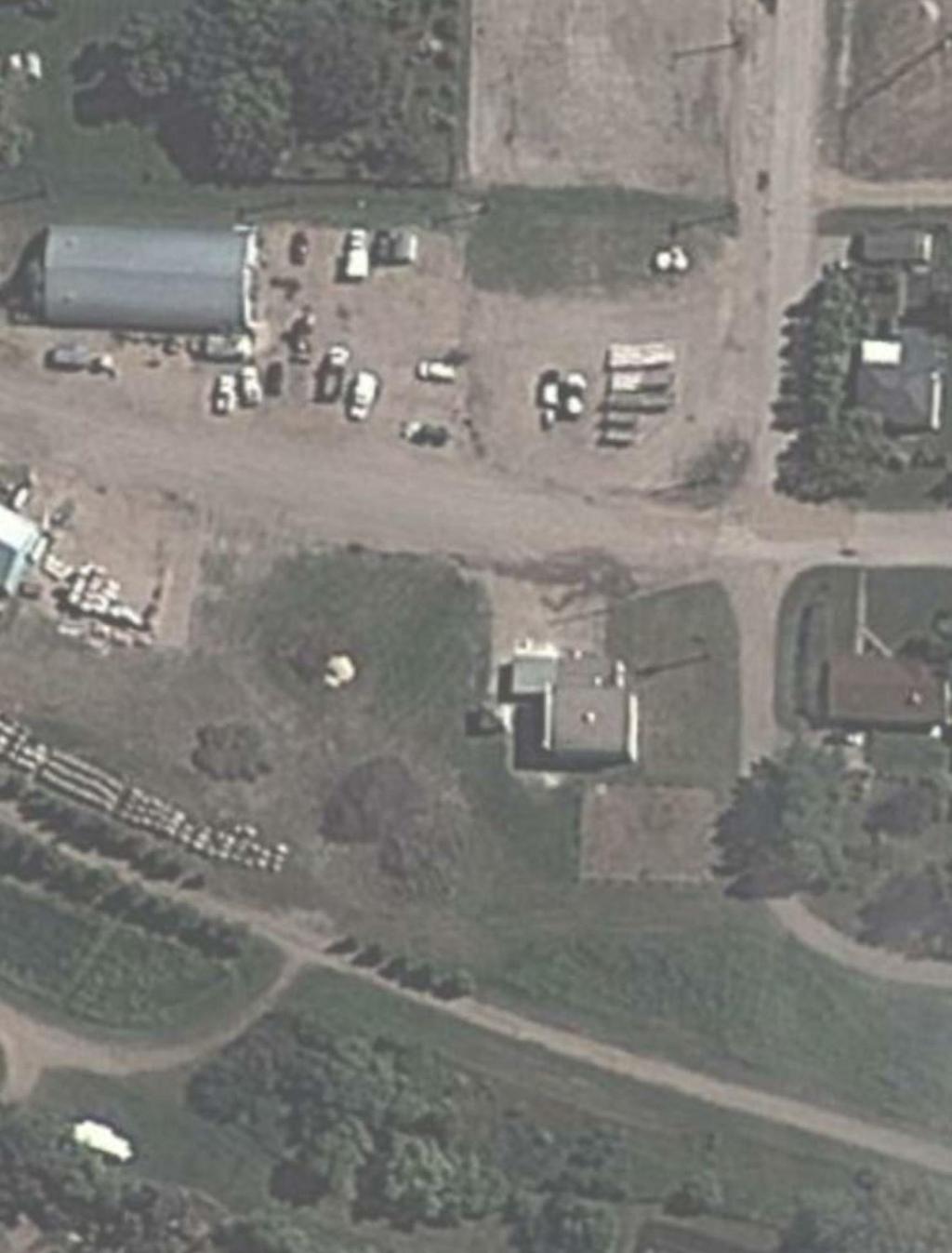
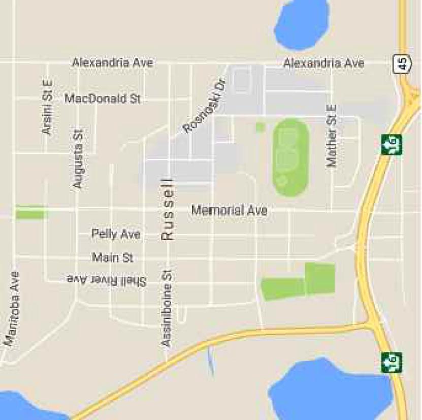
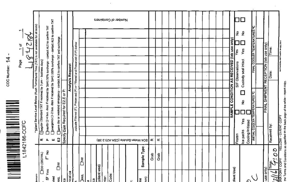
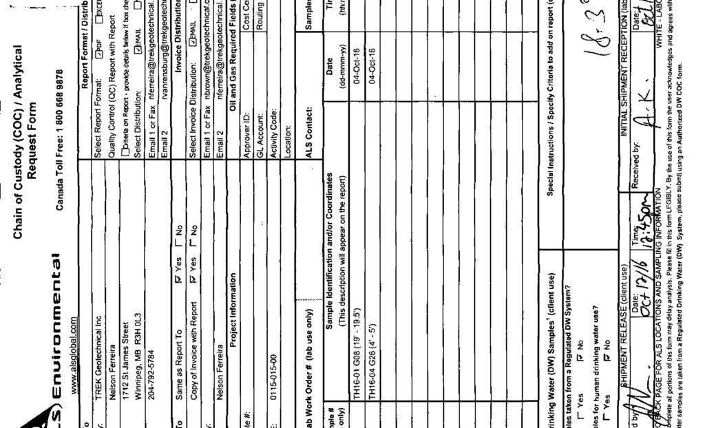
7 This report summarizes the results of the geotechnical investigation completed by TREK Geotechnical Inc. (TREK) for the proposed new water treatment plant (WTP) in the town of Russell, MB. The terms of reference for the investigation are included in our proposal addressed to Ken Anderson of Associated Engineering (Associated) dated September 8, The current scope of work includes a subsurface investigation, laboratory testing, and the provision of recommendations for the design and construction of foundations. Recommendations for lateral earth pressures for permanent walls, excavations and shoring, backfill, site drainage considerations, foundation concrete, quality control materials testing and inspection services are also included. The project site is located along the west side of Ellice Ave. N between Darcy St. and Augusta St. The existing brick WTP building and existing reservoir are situated on the south end of the site (on the corner of Darcy Str. and Ellice Ave.) and the new proposed WTP with a below ground reservoir is to be constructed north of the existing water treatment building. The new WTP building will be roughly 20 m wide by 23 m long and will likely be founded on a concrete raft foundation at a depth of approximately 3.2 m below existing grade. A subsurface investigation was undertaken on October 4 th, 2016 under the supervision of TREK personnel to evaluate the subsurface conditions at the site. Four test holes (TH16-01 to 04) were drilled within the vicinity of the new building for the provision of foundation recommendations. The test holes were drilled to power auger refusal at depths ranging from 4.9 to 6.4 m in all test holes. The test holes were drilled using an Acker SSIII track-mounted drill rig equipped with 125 mm solid stem augers and backfilled using auger cuttings. A standpipe piezometer, SP16-01 was installed in a separate hole adjacent to TH Subsurface soils encountered during drilling were visually classified based on the Unified Soil Classification System (USCS). Disturbed auger cuttings and split spoon samples collected during drilling were transported to TREK s testing laboratory in Winnipeg, MB for further classification and laboratory testing. Laboratory testing consisted of water content determination on all samples and Atterberg limit and hydrometer testing on select samples. Water soluble sulphate tests were done by ALS Environmental to determine the soluble sulphate in the soil to assist in providing the provision for design of foundation concrete, or any other concrete that will be in contact with the soils at site. Test hole locations (shown on Figure 01) were determined by handheld GPS and measured from stakes in ground that were assumed to denote the corners of new water treatment plant. Test hole elevations were surveyed using a rod and level relative to the top of the southeast corner of the concrete pad
8 located at the existing reservoir (denoted as TBM 1 on Figure 01), which was assigned an arbitrary elevation of m. The test hole logs attached to this report include a description of the soil units encountered during drilling and other pertinent information such as groundwater conditions and a summary of the laboratory testing results. A brief description of the soil units encountered at the test hole locations are provided below. All interpretations of soil stratigraphy for the purposes of design should refer to the detailed information provided on the attached test hole logs. The soil stratigraphy at the site generally consists of (in descending order): Fill Clay and Silt Till Sand and Silt Clay Till Clay Shale The fill consists of varying amounts of clay, silt, sand and gravel and ranges in thickness between 0.8 to 1.3 m. Clay and silt till was encountered below the fill and contains varying amounts of clay, silt, sand and gravel. Layers of silt and sand were encountered at various depths within or above the till at three of the four test hole locations. The clay and silt till layers are generally brown of colour, moist, stiff to very stiff and is of intermediate to high plasticity. Soil-like silty clay shale was encountered at depths of 4.3 to 4.6 m which extended to the depth of exploration (power auger refusal) in all test holes. The clay shale is, non-cemented ( soil-like ), grey, moist, hard, and is of high plasticity. A ~25 mm thick sand seam was encountered in the clay shale at 4.9 m in TH16-01 from which seepage was observed. Seepage was encountered in three of the four test holes while sloughing occurred in two of the four test holes. Seepage and sloughing was not observed in TH Seepage tended to occur within the sand and silt layers or thin sand seams (TH16-01, TH16-02 and TH16-03) while sloughing occurred within the fill (TH16-03) or within sand layers (TH16-02). Ground water levels were measured upon completion of drilling and ranged between 0.9 m depth (TH16-02) to 5.2 m depth (TH16-01). A standpipe piezometer was installed in TH16-01 at ~6.0 m depth to determine groundwater levels in the clay shale. The ground water level in the standpipe piezometer was measured at 1.62 m below ground surface (~Elev m) by WTP personnel on November 14 th, The groundwater observations made during drilling are short-term and should not be considered
9 reflective of (static) groundwater levels at the site which would require monitoring over an extended period of time to determine. It is important to recognize that groundwater conditions may vary seasonally, annually, or as a result of construction activities. Based on the subsurface conditions and the anticipated magnitude of applied loading from the structures, a raft foundation will likely be the most suitable foundation type for this site. Limit states design and construction recommendations in accordance with the National Building Code of Canada (NBCC 2010) for these foundation types are provided below. It should be understood that shallow foundations are subject to vertical movements due to seasonal moisture and volume changes and freeze/thaw cycles (i.e. frost action) of the underlying clayey soils. In regard to frost action, the depth of frost penetration is approximately 2.5 m below existing ground surface. In this regard, if shallow foundations are to be installed within the frost zone, insulation should be considered or surrounding grades should be raised to provide an equivalent frost depth of 2.5 m. Given the relatively high groundwater level at the site and the nature of the soils that will be encountered during excavation, dewatering of the excavation for the raft foundation will likely be required. Dewatering will likely require that a series of wells or wellpoints be installed around the proposed excavation area. The wells or wellpoints will need to be pumped until groundwater levels within the work area are lowered to below the design excavation depth. Limit States Design recommendations for shallow foundations in accordance with the National Building Code of Canada (NBCC 2010) are provided below. Limit States Design requires consideration of distinct loading scenarios comparing the structural loads to the foundation bearing capacity using resistance and load factors that are based on reliability criteria. Two general design scenarios are evaluated corresponding to the serviceability and ultimate capacity requirements. The Ultimate Limit State (ULS) is concerned with ensuring that the maximum structural loads do not exceed the nominal (ultimate) capacity of the foundation units. The ULS foundation bearing capacity is obtained by multiplying the nominal (ultimate) bearing capacity by a resistance factor (reduction factor), which is then compared to the factored (increased) structural loads. The ULS bearing capacity must be greater than or equal to the maximum factored load. Table 1 summarizes the resistance factors that can be used for the design of shallow foundations as per the National Building Code of Canada (NBCC 2010). The values of the resistance factors depend on the method of analysis and verification testing completed during construction. The Service Limit State (SLS) is concerned with limiting deformation or settlement of the foundation under service loading conditions such that the integrity of the structure will not be impacted. The SLS should generally be analysed by calculating the settlement resulting from applied service loads and comparing this to the settlement tolerance of the structure. However, the settlement tolerance of the structure is typically not defined at the preliminary design stage. As such, SLS bearing capacities are
10 often provided that are developed on the basis of limiting settlement to 25 mm or less. A more detailed settlement analysis should be conducted to refine the estimated settlement and/or adjust the SLS bearing resistances if a more stringent settlement tolerance is required. Table 1. ULS Resistance Factor for Shallow Foundations (NBCC 2010) Case Resistance Factor Shallow Foundations Bearing Resistance 0.5 A raft foundation bearing on clay tills will be subject to some seasonal movement associated with moisture changes in clay soils. Provided that this is acceptable the raft foundation installed at 3.2 m depth can be designed using a SLS bearing resistance of 200 kpa and an ULS bearing resistance of 300 kpa These resistances are based on the foundation bearing on very stiff to hard clay till. Additional recommendations for design and construction of the raft are provided below. Additional considerations for the design and construction of the raft foundation are provided below. 1. Organics, fill soils, silts, clays and any other deleterious materials should be stripped away such that the subgrade only consists of native, undisturbed very stiff clay till. Excavation should be completed by an excavator equipped with a smooth bladed bucket in a manner which minimizes disturbance to the exposed subgrade. Care should be taken not to over-excavate and to minimize the subgrade disturbance at all times. A raft placed on a disturbed bearing surface will result in a reduction in SLS resistance and may lead to intolerable settlement over time. 2. If over-excavation occurs the grades should be raised using Manitoba Infrastructure Class A granular base course compacted to 98% of Standard Proctor Maximum Dry Density (SPMDD). 3. The final bearing surface should be inspected and documented by TREK Geotechnical prior to concrete placement to verify the adequacy of the bearing surface and proper installation of the raft. 4. Utility lines connecting to the expansion (e.g. a line passing through a wall of the expansion) should be designed to accommodate differential movements. 5. The bearing surface should be protected from freezing, drying, or inundation with water at all times during construction. If any of these conditions occur, the sub-grade should be scarified, moisture conditioned as appropriate, and re-compacted to a minimum of 95% of the SPMDD. 6. The raft should be designed by a qualified structural engineer to resist all applied loads from the proposed structures and uplift due to the high groundwater table. Buried concrete structures can be subject to ad-freezing forces acting along their vertical surfaces. For foundation components located within the depth of frost penetration, an uplift adhesion of 65 kpa is recommended for design. These forces will be resisted by structural dead loads (unfactored) and uplift
11 resistance afforded by the length of the foundations system below the depth of frost penetration. A frost penetration depth of 2.5 m should be assumed for design. Based on the anticipated depth of the raft foundation (3.2 m) the anticipated frost penetration depth should not be a concern. All foundation concrete should be designed by a qualified structural engineer for the anticipated axial (compression and uplift), lateral, and bending loads from the structure and seasonal movements. Based on test results on samples G08 and G26, the degree of exposure for concrete subjected to sulphate attack is classified as moderate according to Table 3, CSA A (Concrete Materials and Methods of Concrete Construction). Accordingly, all concrete in contact with the native soil should be made with sulphate-resistant cement (MS or MSb). Furthermore, concrete which may be exposed to freezing and thawing should be adequately air entrained to improve freeze-thaw durability in accordance with Table 4, CSA A In accordance with Section Field Review of the NBCC (2010), the designer or other suitably qualified person shall carry out a field review on: 1. a continuous basis during: i. the construction of all deep foundation units, ii. the installation and removal of retaining structures and related backfilling operations, and iii. during the placement of engineered fills. 2. on an as-required basis for the construction of shallow foundation units and in excavating, dewatering and other related works. In consideration of the above and relative to this particular project, we recommend that TREK, as the geotechnical engineer of record, be retained to inspect the installation of the raft foundation. TREK is familiar with the geotechnical conditions and the basis for the foundation recommendations and can provide any design modifications deemed to be necessary should altered subsurface conditions be encountered. The magnitude of lateral earth pressures from retained soil against the component walls will depend on the backfill material type, methods of placing and compacting the backfill, and the magnitude of horizontal deflection of the wall after the backfill is placed. It is recommended that free draining granular fill be used as backfill against the structure walls to improve drainage properties and minimize the potential of lateral frost heave loading. Given that the bottom of the excavation is expected to be below the water table, a sub-drainage system is not recommended, rather the expansion walls should be design to withstand a hydrostatic water pressure at ground surface in addition to the lateral earth pressure.
12 Cohesive soils should not be used as backfill against the walls as these soils could generate excessive lateral earth pressures from swelling. An at-rest earth pressure coefficient (K o ) of 0.5 should be used for structural design of the structure walls. An appropriate surface surcharge should be included in the earth pressure distribution to account for surface loads. Over-compaction of the backfill soils adjacent to the WTP walls may result in earth pressures that are considerably higher that those predicted in design. Compaction of the granular fills within about 1.5 m of any wall should be conducted with a light hand operated vibrating plate compactor and the number of compaction passes should be limited. A maximum compacted density of 92% of Standard Proctor Maximum Dry Density (SPMDD) should be reviewed during construction to verify that they are consisted with the design assumptions. Beyond 1.5m from component walls, excavations should be backfilled with granular fill that is free of debris, organics and any other deleterious materials. The fill should be compacted to 98% of the Standard Proctor Maximum Dry Density (SPMDD) in lift thicknesses not exceeding 150 mm. Even with this level of compaction some settlement of the fill should be expected; the settlement could be in the order of approximately 1 to 2% of the fill thickness. All excavations must be carried out in compliance with the appropriate regulation(s) under the Manitoba Workplace Safety and Health Act. Any open-cut excavations greater than 3 m deep must be designed and sealed by a professional engineer and should be reviewed by the geotechnical engineer of record (TREK). TREK anticipates that short term stability can be maintained for open-cut excavations shallower than 3 m with side slopes no steeper than 1 horizontal to 1 vertical (1H:1V). Should this not be the case, or if existing (adjacent) structures or infrastructure prevent an open excavation, TREK can provide recommendations and design parameters for shoring systems upon request. Excavations must be designed to prevent undermining of existing foundations and to accommodate construction of the reservoir in a safe manner. Once a final foundation plan is developed, TREK should be contacted to review the plan. Maintaining the stability of the excavation slopes for the duration of construction should be the responsibility of the Contractor. To prevent wetting or drying of the exposed excavation side slopes, they should be protected with plastic covering or similar measures. Stockpiles of excavated material and heavy equipment should be kept away from the edge of the excavation by a distance equal to or greater than the depth of excavation. Dewatering measures should be completed as necessary to maintain a dry excavation and permit proper completion of the work. If seepage is encountered, it should be directed to a sump pit and pumped out of the excavation. If significant seepage is observed during excavation, wellpoints should be installed to dewater the excavation for the new WTP. Surface water should be diverted away from the excavation
13 and the excavation should be backfilled as soon as possible following construction. A dewatering plan should be prepared by the contractor and submitted for review by TREK prior to work proceeding onsite. Drainage adjacent to buildings should promote runoff away from the structures. Water discharge from roof leaders should be directed away from the structures and positive site drainage around the perimeter of the structures should be provided at a gradient of at least 2% to promote runoff away from the structures. The geotechnical information provided in this report is in accordance with current engineering principles and practices (Standard of Practice). The findings of this report were based on information provided (field investigation and laboratory testing). Soil conditions are natural deposits that can be highly variable across a site. If subsurface conditions are different than the conditions previously encountered on-site or those presented here, we should be notified to adjust our findings if necessary. All information provided in this report is subject to our standard terms and conditions for engineering services, a copy of which is provided to each of our clients with the original scope of work or standard engineering services agreement. If these conditions are not attached, and you are not already in possession of such terms and conditions, contact our office and you will be promptly provided with a copy. This report has been prepared by TREK Geotechnical Inc. (the Consultant) for the exclusive use of Associated Engineering (the Client) and their agents for the work product presented in the report. Any findings or recommendations provided in this report are not to be used or relied upon by any third parties, except as agreed to in writing by the Client and Consultant prior to use.
14

15
16
17
18
19
20
21

22

23

24 MEMORANDUM Date October 25, 2016 To From Nelson Ferreira, TREK Geotechnical Paul Bevel, TREK Geotechnical Project No Project Subject Distribution Russell Water Treatment Plant Laboratory Testing Results Lab Req. R559 Reinhardt Van Rensburg Attached are the laboratory testing results for the above noted project. The testing included moisture content determinations, grain size analysis (mechanical sieve) and Atterberg limits Kind Regards, Paul Bevel Attach.
25 Moisture Content Report ASTM D Project No Client Associated Engineering Project Russell Water Treatment Plant Sample Date Test Date Technician 06-Oct Oct-16 HS Test Pit TH16-01 TH16-01 TH16-01 TH16-01 TH16-01 TH16-01 Depth (m) Sample # G01 G02 G03 G04 G05 G06 Tare ID F40 Z112 P07 F1 Z07 Z123 Mass of tare Mass wet + tare Mass dry + tare Mass water Mass dry soil Moisture % 22.6% 23.2% 19.0% 19.9% 17.4% 16.9% Test Pit TH16-01 TH16-01 TH16-01 TH16-02 TH16-02 TH16-02 Depth (m) Sample # G07 G08 SS09 G10 G11 G12 Tare ID Z42 E17 P29 D10 E60 AA22 Mass of tare Mass wet + tare Mass dry + tare Mass water Mass dry soil Moisture % 29.8% 33.7% 37.6% 17.7% 27.3% 45.3% Test Pit TH16-02 TH16-02 TH16-02 TH16-03 TH16-03 TH16-03 Depth (m) Sample # G13 SS14 SS15 G16 G17 G18 Tare ID AA20 AB93 N01 Z100 AA02 Z41 Mass of tare Mass wet + tare Mass dry + tare Mass water Mass dry soil Moisture % 18.5% 17.5% 37.6% 39.5% 29.0% 31.8% TREK Moisture Content & Toss Page 1 of 2
26 Moisture Content Report ASTM D Project No Client Associated Engineering Project Russell Water Treatment Plant Sample Date Test Date Technician 06-Oct Oct-16 HS Test Pit TH16-03 TH16-03 TH16-03 TH16-03 TH16-03 TH16-04 Depth (m) Sample # SS19 G20 G21 SS22 SS23 G24 Tare ID F7 D27 H5 AB54 AC20 AA06 Mass of tare Mass wet + tare Mass dry + tare Mass water Mass dry soil Moisture % 41.9% 27.4% 19.8% 17.2% 32.0% 27.0% Test Pit TH16-04 TH16-04 TH16-04 TH16-04 TH16-04 Depth (m) Sample # G25 G26 SS27 SS28 SS29 Tare ID E77 W111 Z36 AA21 K39 Mass of tare Mass wet + tare Mass dry + tare Mass water Mass dry soil Moisture % 34.9% 22.4% 27.5% 17.5% 26.9% Test Pit Depth (m) Sample # Tare ID Mass of tare Mass wet + tare Mass dry + tare Mass water Mass dry soil Moisture % TREK Moisture Content & Toss Page 2 of 2
27 Atterberg Limits ASTM D e1 Project No Client Associated Engineering Project Russell Water Treatment Plant Test Hole TH16-01 Sample # G07 Depth (m) Sample Date 06-Oct-16 Liquid Limit 59 Test Date 18-Oct-16 Plastic Limit 35 Technician MM Plasticity Index 24 Liquid Limit Trial # Number of Blows (N) Mass Wet Soil + Tare (g) Mass Dry Soil + Tare (g) Mass Tare (g) Mass Water (g) Mass Dry Soil (g) Moisture Content (%) Moisture Content (%) Number of Blows (N) Plastic Limit Trial # Mass Wet Soil + Tare (g) Mass Dry Soil + Tare (g) Mass Tare (g) Mass Water (g) Mass Dry Soil (g) Moisture Content (%) TREK Atterberg - TH16-01-G07 Page 1 of 1
28 Atterberg Limits ASTM D e1 Project No Client Associated Engineering Project Russell Water Treatment Plant Test Hole TH16-02 Sample # SS14 Depth (m) Sample Date 06-Oct-16 Liquid Limit 34 Test Date 18-Oct-16 Plastic Limit 18 Technician MM Plasticity Index 16 Liquid Limit Trial # Number of Blows (N) Mass Wet Soil + Tare (g) Mass Dry Soil + Tare (g) Mass Tare (g) Mass Water (g) Mass Dry Soil (g) Moisture Content (%) Moisture Content (%) Number of Blows (N) Plastic Limit Trial # Mass Wet Soil + Tare (g) Mass Dry Soil + Tare (g) Mass Tare (g) Mass Water (g) Mass Dry Soil (g) Moisture Content (%) TREK Atterberg - TH16-02-SS14 Page 1 of 1
29 Atterberg Limits ASTM D e1 Project No Client Associated Engineering Project Russell Water Treatment Plant Test Hole TH16-03 Sample # G18 Depth (m) Sample Date 06-Oct-16 Liquid Limit 42 Test Date 18-Oct-16 Plastic Limit 24 Technician MM Plasticity Index 18 Liquid Limit Trial # Number of Blows (N) Mass Wet Soil + Tare (g) Mass Dry Soil + Tare (g) Mass Tare (g) Mass Water (g) Mass Dry Soil (g) Moisture Content (%) Moisture Content (%) Number of Blows (N) Plastic Limit Trial # Mass Wet Soil + Tare (g) Mass Dry Soil + Tare (g) Mass Tare (g) Mass Water (g) Mass Dry Soil (g) Moisture Content (%) TREK Atterberg - TH16-03-G18 Page 1 of 1
30 Atterberg Limits ASTM D e1 Project No Client Associated Engineering Project Russell Water Treatment Plant Test Hole TH16-03 Sample # SS23 Depth (m) Sample Date 06-Oct-16 Liquid Limit 55 Test Date 18-Oct-16 Plastic Limit 38 Technician MM Plasticity Index 16 Liquid Limit Trial # Number of Blows (N) Mass Wet Soil + Tare (g) Mass Dry Soil + Tare (g) Mass Tare (g) Mass Water (g) Mass Dry Soil (g) Moisture Content (%) Moisture Content (%) Number of Blows (N) Plastic Limit Trial # Mass Wet Soil + Tare (g) Mass Dry Soil + Tare (g) Mass Tare (g) Mass Water (g) Mass Dry Soil (g) Moisture Content (%) TREK Atterberg - TH16-03-SS23 Page 1 of 1
31 Atterberg Limits ASTM D e1 Project No Client Associated Engineering Project Russell Water Treatment Plant Test Hole TH16-04 Sample # SS27 Depth (m) Sample Date 06-Oct-16 Liquid Limit 25 Test Date 18-Oct-16 Plastic Limit 18 Technician MM Plasticity Index 7 Liquid Limit Trial # Number of Blows (N) Mass Wet Soil + Tare (g) Mass Dry Soil + Tare (g) Mass Tare (g) Mass Water (g) Mass Dry Soil (g) Moisture Content (%) Moisture Content (%) Number of Blows (N) Plastic Limit Trial # Mass Wet Soil + Tare (g) Mass Dry Soil + Tare (g) Mass Tare (g) Mass Water (g) Mass Dry Soil (g) Moisture Content (%) TREK Atterberg - TH16-04-SS27 Page 1 of 1
32 Atterberg Limits ASTM D e1 Project No Client Associated Engineering Project Russell Water Treatment Plant Test Hole TH16-04 Sample # SS28 Depth (m) Sample Date 06-Oct-16 Liquid Limit 31 Test Date 18-Oct-16 Plastic Limit 15 Technician MM Plasticity Index 16 Liquid Limit Trial # Number of Blows (N) Mass Wet Soil + Tare (g) Mass Dry Soil + Tare (g) Mass Tare (g) Mass Water (g) Mass Dry Soil (g) Moisture Content (%) Moisture Content (%) Number of Blows (N) Plastic Limit Trial # Mass Wet Soil + Tare (g) Mass Dry Soil + Tare (g) Mass Tare (g) Mass Water (g) Mass Dry Soil (g) Moisture Content (%) TREK Atterberg - TH16-04-SS28 Page 1 of 1
33 Grain Size Analysis (Sieve Method) ASTM C ASTM C Project No Client Associated Engineering Project Russell Water Treatment Plant Test Hole TH16-01 Sample # G12 Depth Date Sampled 4-Oct-16 Gravel % 39.3 Date Tested 13-Oct-16 Sand % 43.8 Technician HS Fines % 16.9 Particle Size Distribution Curve Percent Finer by Weight Fines Fine Sand Medium Coarse Fine Gravel Coarse Particle Size (mm) Sieve Opening (mm) Percent Passing Specification (Min - Max) mm Split Size G12 Page 1 of 1
34 Grain Size Analysis (Sieve Method) ASTM C ASTM C Project No Client Associated Engineering Project Russell Water Treatment Plant Test Hole TH16-03 Sample # G21 Depth Date Sampled 4-Oct-16 Gravel % 1.6 Date Tested 13-Oct-16 Sand % 71.1 Technician HS Fines % 27.3 Particle Size Distribution Curve Percent Finer by Weight Fines Fine Sand Medium Coarse Fine Gravel Coarse Particle Size (mm) Sieve Opening (mm) Percent Passing Specification (Min - Max) mm Split Size G21 Page 1 of 1
 FINAL Client Phone: 204-782- 5784 Certificate of Analysis Lab Work Order #: L1842186 Project P.")
35 TREK Geotechnical Inc. ATTN: NELSON FERREIRA 1712 St. James Street Winnipeg MB R3H 0L3 Date Received: Report Date: Version: 12- OCT OCT :09 (MT) FINAL Client Phone: Certificate of Analysis Lab Work Order #: L Project P.O. #: Job Reference: C of C Numbers: Legal Site Desc: Craig Riddell, B.Sc.Ag Account Manager [This report shall not be reproduced except in full without the written authority of the Laboratory.] ADDRESS: 1329 Niakwa Road East, Unit 12, Winnipeg, MB R2J 3T4 Canada Phone: Fax: ALS CANADA LTD Part of the ALS Group A Campbell Brothers Limited Company
36 ALS ENVIRONMENTAL ANALYTICAL REPORT L CONTD... PAGE 2 of 3 Version: FINAL Sample Details/Parameters Result Qualifier* D.L. Units Extracted Analyzed Batch L TH16-01 G08 ( ) Sampled By: CLIENT on 04-OCT-16 Matrix: GRAB Miscellaneous Parameters Water Soluble Sulfate % 19-OCT OCT-16 R L Sampled By: TH16-01 G26 (4-5 ) CLIENT on 04-OCT-16 Matrix: GRAB Miscellaneous Parameters Water Soluble Sulfate % 19-OCT OCT-16 R * Refer to Referenced Information for Qualifiers (if any) and Methodology.
37 Reference Information L CONTD... PAGE 3 of 3 Version: FINAL Test Method References: ALS Test Code Matrix Test Description Method Reference** SO4-WATER-SOL-SK Soil Water Soluble Sulfate (6 hour 1:10) CSA A23.2-3B (CONCRETE) ** ALS test methods may incorporate modifications from specified reference methods to improve performance. The last two letters of the above test code(s) indicate the laboratory that performed analytical analysis for that test. Refer to the list below: Laboratory Definition Code SK Laboratory Location ALS ENVIRONMENTAL - SASKATOON, SASKATCHEWAN, CANADA Chain of Custody Numbers: GLOSSARY OF REPORT TERMS Surrogates are compounds that are similar in behaviour to target analyte(s), but that do not normally occur in environmental samples. For applicable tests, surrogates are added to samples prior to analysis as a check on recovery. In reports that display the D.L. column, laboratory objectives for surrogates are listed there. mg/kg - milligrams per kilogram based on dry weight of sample mg/kg wwt - milligrams per kilogram based on wet weight of sample mg/kg lwt - milligrams per kilogram based on lipid-adjusted weight mg/l - unit of concentration based on volume, parts per million. < - Less than. D.L. - The reporting limit. N/A - Result not available. Refer to qualifier code and definition for explanation. Test results reported relate only to the samples as received by the laboratory. UNLESS OTHERWISE STATED, ALL SAMPLES WERE RECEIVED IN ACCEPTABLE CONDITION. Analytical results in unsigned test reports with the DRAFT watermark are subject to change, pending final QC review.
38
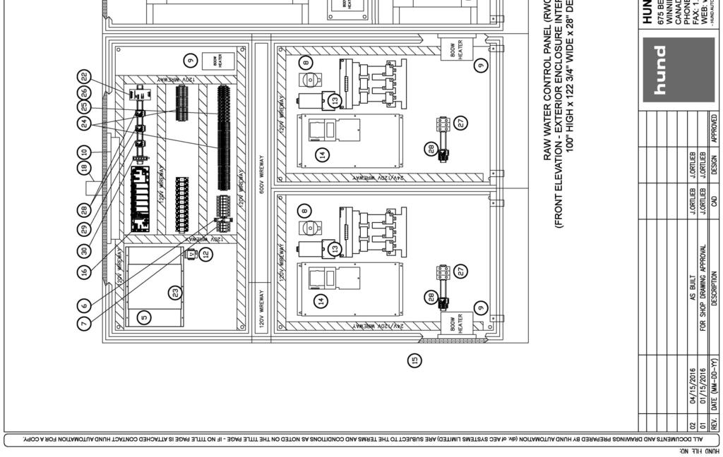
39 Municipality of Russell Binscarth Russell WTP and Associated Works MWSB#; AE#: Section z - Appendix B APPENDIX B APPENDIX B EQUIPMENT SUPPLIER INFORMATION
40 TOWN OF RUSSELL WTP - FIELD WIRING SCHEDULE Note: This schedule lists all known field connections, except for connections between CP-1000 WTP PLC Panel and various connections not fully specified in RFP: Field instruments and valves to be supplied by General Contractor, MCC connections for motor control/status, automatic transfer switch status, generator status, and any other connections that are unspecified in the RFP. DELCO P&ID AE P&ID Delco Tag AE Tag End 1 (Device) End 2 Signal Cabling Signal Type Power Device Location (Approximate) Model MTU-PID RFP-P-004 FV-4115 FV-4115 Solenoid Valve Post-SBS CL Analyzer CP MTU RIO Panel Open Command 2-#14 120VAC Disc. Out - Water Treatment Plant EWP 120VAC Coil MTU-PID RFP-P-004 AIT-4002 AIT-4002 Post-SBS CL Analyzer 120VAC Building Circuit Power 2-#14, #14 Ground Power Supply 120VAC Water Treatment Plant Hach CL CP MTU RIO Panel Chlorine Level Indication 1 PR-18GA, Twisted, Shielded Analog 4-20mA - Fault Signal 2-#18 24VDC Disc. Contact In - MTU-PID RFP-P-004 FV-4109 FV-4109 Solenoid Valve Pre-SBS CL Analyzer CP MTU RIO Panel Open Command 2-#14 120VAC Disc. Out - Water Treatment Plant EWP 120VAC Coil MTU-PID RFP-P-004 AIT-4001 AIT-4001 Pre-SBS CL Analyzer 120VAC Building Circuit Power 2-#14, #14 Ground Power Supply 120VAC Water Treatment Plant Hach CL CP MTU RIO Panel Chlorine Level Indication 1 PR-18GA, Twisted, Shielded Analog 4-20mA - Fault Signal 2-#18 24VDC Disc. Contact In - MTU-PID RFP-P-004 FIT-4201 FIT-4201 RO Bypass Flow Mag Meter CP MTU RIO Panel Power 2-#14, #14 Ground Power Supply 24VDC Water Treatment Plant E&H Promag 10 Flow Rate 2PR-18GA, Twisted, Shielded Analog 4-20mA - Flow Quantity 24VDC Disc Pulse - MTU-PID RFP-P-004 FCV-4102 FCV-4102 RO Bypass Control Valve CP MTU RIO Panel Power 2-#14, #14 Ground Power Supply 120VAC Water Treatment Plant Bray Electric w/ servo kit Analog signal 1 PR-18GA, Twisted, Shielded Analog 4-20mA - Closed Status 2-#18 120VAC Disc. Contact In - CHEM-PID RFP-P-005 PMP KMN-1101 Oxidant Dosing Pump 1 CP MTU PLC Panel AC receptacle Power 2-#14, #14 Ground Power Supply 120VAC Chemical Room Grundfos DDA Enable Command 6-#18 Contact Out - Pulse Command Contact Out - Fault Status 24VDC Disc. Contact In - Flow Indication 1 PR-18GA, Twisted, Shielded Analog 4-20mA - CHEM-PID RFP-P-005 PMP KMN-1102 Oxidant Dosing Pump 2 CP MTU PLC Panel AC receptacle Power 2-#14, #14 Ground Power Supply 120VAC Chemical Room Grundfos DDA Enable Command 6-#18 Contact Out - Pulse Command Contact Out - Fault Status 24VDC Disc. Contact In - Flow Indication 1 PR-18GA, Twisted, Shielded Analog 4-20mA - CHEM-PID RFP-P-005 PMP ASC-3201 Anti-Scalant Dosing Pump 1 CP MTU PLC Panel AC receptacle Power 2-#14, #14 Ground Power Supply 120VAC Chemical Room Grundfos DDA Enable Command 6-#18 Contact Out - Pulse Command Contact Out - Fault Status 24VDC Disc. Contact In - Flow Indication 1 PR-18GA, Twisted, Shielded Analog 4-20mA - CHEM-PID RFP-P-005 PMP ASC-3202 Anti-Scalant Dosing Pump 2 CP MTU PLC Panel AC receptacle Power 2-#14, #14 Ground Power Supply 120VAC Chemical Room Enable Command 6-#18 Contact Out - Grundfos DDA Pulse Command Contact Out - Fault Status 24VDC Disc. Contact In - Flow Indication 1 PR-18GA, Twisted, Shielded Analog 4-20mA -
41 TOWN OF RUSSELL WTP - FIELD WIRING SCHEDULE Note: This schedule lists all known field connections, except for connections between CP-1000 WTP PLC Panel and various connections not fully specified in RFP: Field instruments and valves to be supplied by General Contractor, MCC connections for motor control/status, automatic transfer switch status, generator status, and any other connections that are unspecified in the RFP. DELCO P&ID AE P&ID Delco Tag AE Tag End 1 (Device) End 2 Signal Cabling Signal Type Power Device Location (Approximate) Model CHEM-PID RFP-P-005 PMP SBS-3101 Reducing Agent Dosing Pump 1 CP MTU PLC Panel AC receptacle Power 2-#14, #14 Ground Power Supply 120VAC Chemical Room Grundfos DDA Enable Command 6-#18 Contact Out - Pulse Command Contact Out - Fault Status 24VDC Disc. Contact In - Flow Indication 1 PR-18GA, Twisted, Shielded Analog 4-20mA - CHEM-PID RFP-P-005 PMP SBS-3102 Reducing Agent Dosing Pump 2 CP MTU PLC Panel AC receptacle Power 2-#14, #14 Ground Power Supply 120VAC Chemical Room Enable Command 6-#18 Contact Out - Grundfos DDA Pulse Command Contact Out - Fault Status 24VDC Disc. Contact In - Flow Indication 1 PR-18GA, Twisted, Shielded Analog 4-20mA - CHEM-PID RFP-P-005 PMP SBS-6101 Reducing Agent Dosing Pump 3 CP MTU PLC Panel AC receptacle Power 2-#14, #14 Ground Power Supply 120VAC Chemical Room Grundfos DDA Enable Command 6-#18 Contact Out - Pulse Command Contact Out - Fault Status 24VDC Disc. Contact In - Flow Indication 1 PR-18GA, Twisted, Shielded Analog 4-20mA - CHEM-PID-001 N/A PMP-5711 N/A Reducing Agent Dosing Pump 4 CP MTU PLC Panel AC receptacle Power 2-#14, #14 Ground Power Supply 120VAC Chemical Room Enable Command 6-#18 Contact Out - Grundfos DDA Pulse Command Contact Out - Fault Status 24VDC Disc. Contact In - CHEM-PID RFP-P-005 PMP CAU-5101 Caustic Dosing Pump 1 CP MTU PLC Panel AC receptacle Power 2-#14, #14 Ground Power Supply 120VAC Chemical Room Grundfos DDA Enable Command 6-#18 Contact Out - Pulse Command Contact Out - Fault Status 24VDC Disc. Contact In - Flow Indication 1 PR-18GA, Twisted, Shielded Analog 4-20mA - CHEM-PID RFP-P-005 PMP CAU-5102 Caustic Dosing Pump 2 CP MTU PLC Panel AC receptacle Power 2-#14, #14 Ground Power Supply 120VAC Chemical Room Grundfos DDA Enable Command 6-#18 Contact Out - Pulse Command Contact Out - Fault Status 24VDC Disc. Contact In - CHEM-PID-001 N/A PMP-5411 N/A Flow Indication 1 PR-18GA, Twisted, Shielded Analog 4-20mA - Caustic Dosing Pump 3 CP MTU PLC Panel AC receptacle Power 2-#14, #14 Ground Power Supply 120VAC Chemical Room Grundfos DDA Enable Command 6-#18 Contact Out - Pulse Command Contact Out - Fault Status 24VDC Disc. Contact In -
42 TOWN OF RUSSELL WTP - FIELD WIRING SCHEDULE Note: This schedule lists all known field connections, except for connections between CP-1000 WTP PLC Panel and various connections not fully specified in RFP: Field instruments and valves to be supplied by General Contractor, MCC connections for motor control/status, automatic transfer switch status, generator status, and any other connections that are unspecified in the RFP. DELCO P&ID AE P&ID Delco Tag AE Tag End 1 (Device) End 2 Signal Cabling Signal Type Power Device Location (Approximate) Model CHEM-PID RFP-P-005 PMP CDP-5201 Disinfectant Dosing Pump 1 CP MTU PLC Panel AC receptacle Power 2-#14, #14 Ground Power Supply 120VAC Chemical Room Grundfos DDA Enable Command 6-#18 Contact Out - Pulse Command Contact Out - Fault Status 24VDC Disc. Contact In - Flow Indication 1 PR-18GA, Twisted, Shielded Analog 4-20mA - CHEM-PID RFP-P-005 PMP CDP-5202 Disinfectant Dosing Pump 2 CP MTU PLC Panel AC receptacle Power 2-#14, #14 Ground Power Supply 120VAC Chemical Room Grundfos DDA Enable Command 6-#18 Contact Out - Pulse Command Contact Out - Fault Status 24VDC Disc. Contact In - Flow Indication 1 PR-18GA, Twisted, Shielded Analog 4-20mA - CHEM-PID RFP-P-005 PMP-5810 CIH-5301 Corrosion Inhibitor Dosing Pump CP MTU PLC Panel AC receptacle Power 2-#14, #14 Ground Power Supply 120VAC Chemical Room Enable Command 6-#18 Contact Out - Grundfos DDA Pulse Command Contact Out - Fault Status 24VDC Disc. Contact In - Flow Indication 1 PR-18GA, Twisted, Shielded Analog 4-20mA - CHEM-PID RFP-P-005 PMP FLU-5401 Fluoride Dosing Pump 1 CP MTU PLC Panel AC receptacle Power 2-#14, #14 Ground Power Supply 120VAC Chemical Room Grundfos DDA Enable Command 6-#18 Contact Out - Pulse Command Contact Out - Fault Status 24VDC Disc. Contact In - Flow Indication 1 PR-18GA, Twisted, Shielded Analog 4-20mA - CHEM-PID RFP-P-005 PMP FLU-5402 Fluoride Dosing Pump 2 CP MTU PLC Panel AC receptacle Power 2-#14, #14 Ground Power Supply 120VAC Chemical Room Enable Command 6-#18 Contact Out - Grundfos DDA Pulse Command Contact Out - Fault Status 24VDC Disc. Contact In - Flow Indication 1 PR-18GA, Twisted, Shielded Analog 4-20mA - CHEM-PID RFP-P-005 MIX-5002 MX-1103 Oxidant Tank Mixer MX VAC Building Circuit Power 2-#14, #14 Ground Power Supply 120VAC Oxidant Tank TBD CIP-PID RFP-P-005 LSH-6019 LSH-3910 CIP Tank High Level Switch CP MTU RIO Panel High Level Status 4-#18 24VDC Disc. Contact In - CIP Tank MDI Float Switch CIP-PID RFP-P-005 LSL-6020 LSL-3909 CIP Tank Low Level Switch CP MTU RIO Panel Low Level Status 4-#18 24VDC Disc. Contact In - CIP Tank MDI Float Switch CIP-PID-001 N/A AIT-6085 N/A CIP ph Sensor AIT-4000F (Hach SC1000) - MTU Train 2 ph Level Indication Hach Analytical Controller Instrument Extension Cable (Supplied by Delco) Digital - CIP Skid ph Sensor To Hach SC1000 CIP-PID-001 N/A TT-6087 N/A CIP Temperature Sensor CP MTU RIO Panel Temp Indication 1 PR-18GA, Twisted, Shielded Analog 4-20mA Loop Powered CIP Skid E&H TMR31 FTR-PID RFP-P-003 FV-1105 FV-1105 Raw Water Sampling Instruments Solenoid Valve CP Filter PLC Panel Open Command 2-#14 120VAC Disc. Out - Greensand Filter Area EWP 120VAC Coil FTR-PID RFP-P-003 AIT-1101 AIT-1101 Instrument Raw Water Turbidity Meter AIT-2000 (Hach SC1000) - Green Sand Filter Area Turbidity Level Indication Hach Analytical Controller Instrument Extension Cable (Supplied by Delco) Digital - Greensand Filter Area Ultraturb Turbidity Sensor To Hach SC1000
43 TOWN OF RUSSELL WTP - FIELD WIRING SCHEDULE Note: This schedule lists all known field connections, except for connections between CP-1000 WTP PLC Panel and various connections not fully specified in RFP: Field instruments and valves to be supplied by General Contractor, MCC connections for motor control/status, automatic transfer switch status, generator status, and any other connections that are unspecified in the RFP. DELCO P&ID AE P&ID Delco Tag AE Tag End 1 (Device) End 2 Signal Cabling Signal Type Power Device Location (Approximate) Model FTR-PID RFP-P-003 FIT-1101 FIT-1101 Raw Water Flow Meter CP Filter PLC Panel Power 2-#14, #14 Ground Power Supply 24VDC Greensand Filter Area E&H Promag 10 Flow Rate 2PR-18GA, Twisted, Shielded Analog 4-20mA - Flow Quantity 24VDC Disc Pulse - FTR-PID-001 N/A AIT-2007 N/A FTR Feed ORP Sensor AIT-2000 (Hach SC1000) - Green Sand Filter Area ORP Level Indication Hach Analytical Controller Instrument Extension Cable (Supplied by Delco) Digital - Greensand Filter Area ORP Sensor To Hach SC1000 FTR-PID RFP-P-003 FV-2101 FV-2101 FTR 1 Vessel Inlet Automated Valve CP Filter PLC Panel Open Status 3-#18 120VAC Disc. Contact In - Greensand Filter Area Bray Series 70 Electric Closed Status 120VAC Disc. Contact In - Open Command 3-#14 120VAC Disc. Out - Close Command 120VAC Disc. Out - FTR-PID RFP-P-003 FV-2104 FV-2104 FTR 1 Backwash Outlet Automated Valve CP Filter PLC Panel Open Status 3-#18 120VAC Disc. Contact In - Greensand Filter Area Bray Series 70 Electric Closed Status 120VAC Disc. Contact In - Open Command 3-#14 120VAC Disc. Out - Close Command 120VAC Disc. Out - FTR-PID RFP-P-003 PT-2110 PIT-2110 FTR 1 Vessel Inlet Pressure Transmitter CP Filter PLC Panel Pressure Indication 1 PR-18GA, Twisted, Shielded Analog 4-20mA Loop Powered Greensand Filter Area Ashcroft G27 FTR-PID RFP-P-003 FV-2105 FV-2105 FTR 1 Vessel Drain Automated Valve CP Filter PLC Panel Open Status 3-#18 120VAC Disc. Contact In - Greensand Filter Area Bray Series 70 Electric Closed Status 120VAC Disc. Contact In - Open Command 3-#14 120VAC Disc. Out - Close Command 120VAC Disc. Out - FTR-PID RFP-P-003 FV-2120 FV-2120 FTR 1 Air Scour Inlet Automated Valve CP Filter PLC Panel Open Status 3-#18 120VAC Disc. Contact In - Greensand Filter Area Bray Series 70 Electric Closed Status 120VAC Disc. Contact In - Open Command 3-#14 120VAC Disc. Out - Close Command 120VAC Disc. Out - FTR-PID RFP-P-003 PT-2111 PIT-2111 FTR 1 Vessel Outlet Pressure Transmitter CP Filter PLC Panel Pressure Indication 1 PR-18GA, Twisted, Shielded Analog 4-20mA Loop Powered Greensand Filter Area Ashcroft G27 FTR-PID RFP-P-003 FV-2151 FV-2151 FTR 1 Filtrate Sampling Instruments Feed Valve CP Filter PLC Panel Open Command 2-#14 120VAC Disc. Out - Greensand Filter Area EWP 120VAC Coil FTR-PID RFP-P-003 AIT-2105 AIT-2105 FTR 1 Filtrate Turbidity Meter AIT-2000 (Hach SC1000) - Green Sand Filter Area Turbidity Level Indication Hach Analytical Controller Instrument Extension Cable (Supplied by Delco) Digital - Greensand Filter Area Ultraturb Turbidity Sensor To Hach SC1000 FTR-PID RFP-P-003 FV-2106 FV-2106 FTR 1 Backwash Inlet Automated Valve CP Filter PLC Panel Open Status 3-#18 120VAC Disc. Contact In - Greensand Filter Area Bray Series 70 Electric Closed Status 120VAC Disc. Contact In - Open Command 3-#14 120VAC Disc. Out - Close Command 120VAC Disc. Out -
44 TOWN OF RUSSELL WTP - FIELD WIRING SCHEDULE Note: This schedule lists all known field connections, except for connections between CP-1000 WTP PLC Panel and various connections not fully specified in RFP: Field instruments and valves to be supplied by General Contractor, MCC connections for motor control/status, automatic transfer switch status, generator status, and any other connections that are unspecified in the RFP. DELCO P&ID AE P&ID Delco Tag AE Tag End 1 (Device) End 2 Signal Cabling Signal Type Power Device Location (Approximate) Model FTR-PID RFP-P-003 FIT-2101 FIT-2101 FTR 1 Vessel Outlet Flow Meter CP Filter PLC Panel Power 2-#14, #14 Ground Power Supply 24VDC Greensand Filter Area E&H Promag 10 Flow Rate 2PR-18GA, Twisted, Shielded Analog 4-20mA - Flow Quantity 24VDC Disc Pulse - FTR-PID RFP-P-003 FCV-2110 FCV-2110 FTR 1 Vessel Outlet Control Valve CP MTU RIO Panel Power 2-#14, #14 Ground Power Supply 120VAC Water Treatment Plant Analog signal 1 PR-18GA, Twisted, Shielded Analog 4-20mA - Bray Electric w/ servo kit Closed Status 2-#18 120VAC Disc. Contact In - FTR-PID RFP-P-003 FV-2107 FV-2107 FTR 1 Forward Flush Outlet Automated Valve CP Filter PLC Panel Open Status 3-#18 120VAC Disc. Contact In - Greensand Filter Area Bray Series 70 Electric Closed Status 120VAC Disc. Contact In - Open Command 3-#14 120VAC Disc. Out - Close Command 120VAC Disc. Out - FTR-PID RFP-P-003 FV-2201 FV-2201 FTR 2 Vessel Inlet Automated Valve CP Filter PLC Panel Open Status 3-#18 120VAC Disc. Contact In - Greensand Filter Area Bray Series 70 Electric Closed Status 120VAC Disc. Contact In - Open Command 3-#14 120VAC Disc. Out - Close Command 120VAC Disc. Out - FTR-PID RFP-P-003 FV-2204 FV-2204 FTR 2 Backwash Outlet Automated Valve CP Filter PLC Panel Open Status 3-#18 120VAC Disc. Contact In - Greensand Filter Area Bray Series 70 Electric Closed Status 120VAC Disc. Contact In - Open Command 3-#14 120VAC Disc. Out - Close Command 120VAC Disc. Out - FTR-PID RFP-P-003 PT-2210 PIT-2210 FTR 2 Vessel Inlet Pressure Transmitter CP Filter PLC Panel Pressure Indication 1 PR-18GA, Twisted, Shielded Analog 4-20mA Loop Powered Greensand Filter Area Ashcroft G27 FTR-PID RFP-P-003 FV-2205 FV-2205 FTR 2 Vessel Drain Automated Valve CP Filter PLC Panel Open Status 3-#18 120VAC Disc. Contact In - Greensand Filter Area Bray Series 70 Electric Closed Status 120VAC Disc. Contact In - Open Command 3-#14 120VAC Disc. Out - Close Command 120VAC Disc. Out - FTR-PID RFP-P-003 FV-2220 FV-2220 FTR 2 Air Scour Inlet Automated Valve CP Filter PLC Panel Open Status 3-#18 120VAC Disc. Contact In - Greensand Filter Area Bray Series 70 Electric Closed Status 120VAC Disc. Contact In - Open Command 3-#14 120VAC Disc. Out - Close Command 120VAC Disc. Out - FTR-PID RFP-P-003 PT-2211 PIT-2211 FTR 2 Vessel Outlet Pressure Transmitter CP Filter PLC Panel Pressure Indication 1 PR-18GA, Twisted, Shielded Analog 4-20mA Loop Powered Greensand Filter Area Ashcroft G27 FTR-PID RFP-P-003 FV-2251 FV-2251 FTR 2 Filtrate Sampling Instruments Feed Valve CP Filter PLC Panel Open Command 2-#14 120VAC Disc. Out - Greensand Filter Area EWP 120VAC Coil FTR-PID RFP-P-003 AIT-2205 AIT-2205 FTR 2 Filtrate Turbidity Meter AIT-2000 (Hach SC1000) - Green Sand Filter Area Turbidity Level Indication Hach Analytical Controller Instrument Extension Cable (Supplied by Delco) Digital - Greensand Filter Area Ultraturb Turbidity Sensor To Hach SC1000
45 TOWN OF RUSSELL WTP - FIELD WIRING SCHEDULE Note: This schedule lists all known field connections, except for connections between CP-1000 WTP PLC Panel and various connections not fully specified in RFP: Field instruments and valves to be supplied by General Contractor, MCC connections for motor control/status, automatic transfer switch status, generator status, and any other connections that are unspecified in the RFP. DELCO P&ID AE P&ID Delco Tag AE Tag End 1 (Device) End 2 Signal Cabling Signal Type Power Device Location (Approximate) Model FTR-PID RFP-P-003 FV-2206 FV-2206 FTR 2 Backwash Inlet Automated Valve CP Filter PLC Panel Open Status 3-#18 120VAC Disc. Contact In - Greensand Filter Area Bray Series 70 Electric Closed Status 120VAC Disc. Contact In - Open Command 3-#14 120VAC Disc. Out - Close Command 120VAC Disc. Out - FTR-PID RFP-P-003 FIT-2201 FIT-2201 FTR 2 Vessel Outlet Flow Meter CP Filter PLC Panel Power 2-#14, #14 Ground Power Supply 24VDC Greensand Filter Area E&H Promag 10 Flow Rate 2PR-18GA, Twisted, Shielded Analog 4-20mA - Flow Quantity 24VDC Disc Pulse - FTR-PID RFP-P-003 FCV-2210 FCV-2210 FTR 2 Vessel Outlet Control Valve CP MTU RIO Panel Power 2-#14, #14 Ground Power Supply 120VAC Water Treatment Plant Analog signal 1 PR-18GA, Twisted, Shielded Analog 4-20mA - Bray Electric w/ servo kit Closed Status 2-#18 120VAC Disc. Contact In - FTR-PID RFP-P-003 FV-2207 FV-2207 FTR 2 Forward Flush Outlet Automated Valve CP Filter PLC Panel Open Status 3-#18 120VAC Disc. Contact In - Greensand Filter Area Bray Series 70 Electric Closed Status 120VAC Disc. Contact In - Open Command 3-#14 120VAC Disc. Out - Close Command 120VAC Disc. Out - FTR-PID RFP-P-003 FV-2301 FV-2301 FTR 3 Vessel Inlet Automated Valve CP Filter PLC Panel Open Status 3-#18 120VAC Disc. Contact In - Greensand Filter Area Bray Series 70 Electric Closed Status 120VAC Disc. Contact In - Open Command 3-#14 120VAC Disc. Out - Close Command 120VAC Disc. Out - FTR-PID RFP-P-003 FV-2304 FV-2304 FTR 3 Backwash Outlet Automated Valve CP Filter PLC Panel Open Status 3-#18 120VAC Disc. Contact In - Greensand Filter Area Bray Series 70 Electric Closed Status 120VAC Disc. Contact In - Open Command 3-#14 120VAC Disc. Out - Close Command 120VAC Disc. Out - FTR-PID RFP-P-003 PT-2310 PIT-2310 FTR 3 Vessel Inlet Pressure Transmitter CP Filter PLC Panel Pressure Indication 1 PR-18GA, Twisted, Shielded Analog 4-20mA Loop Powered Greensand Filter Area Ashcroft G27 FTR-PID RFP-P-003 FV-2305 FV-2305 FTR 3 Vessel Drain Automated Valve CP Filter PLC Panel Open Status 3-#18 120VAC Disc. Contact In - Greensand Filter Area Bray Series 70 Electric Closed Status 120VAC Disc. Contact In - Open Command 3-#14 120VAC Disc. Out - Close Command 120VAC Disc. Out -
46 TOWN OF RUSSELL WTP - FIELD WIRING SCHEDULE Note: This schedule lists all known field connections, except for connections between CP-1000 WTP PLC Panel and various connections not fully specified in RFP: Field instruments and valves to be supplied by General Contractor, MCC connections for motor control/status, automatic transfer switch status, generator status, and any other connections that are unspecified in the RFP. DELCO P&ID AE P&ID Delco Tag AE Tag End 1 (Device) End 2 Signal Cabling Signal Type Power Device Location (Approximate) Model FTR-PID RFP-P-003 FV-2320 FV-2320 FTR 3 Air Scour Inlet Automated Valve CP Filter PLC Panel Open Status 3-#18 120VAC Disc. Contact In - Greensand Filter Area Bray Series 70 Electric Closed Status 120VAC Disc. Contact In - Open Command 3-#14 120VAC Disc. Out - Close Command 120VAC Disc. Out - FTR-PID RFP-P-003 PT-2311 PIT-2311 FTR 3 Vessel Outlet Pressure Transmitter CP Filter PLC Panel Pressure Indication 1 PR-18GA, Twisted, Shielded Analog 4-20mA Loop Powered Greensand Filter Area Ashcroft G27 FTR-PID RFP-P-003 FV-2351 FV-2351 FTR 3 Filtrate Sampling Instruments Feed Valve CP Filter PLC Panel Open Command 2-#14 120VAC Disc. Out - Greensand Filter Area EWP 120VAC Coil FTR-PID RFP-P-003 AIT-2305 AIT-2305 FTR 3 Filtrate Turbidity Meter AIT-2000 (Hach SC1000) - Green Sand Filter Area Turbidity Level Indication Hach Analytical Controller Instrument Extension Cable (Supplied by Delco) Digital - Greensand Filter Area Ultraturb Turbidity Sensor To Hach SC1000 FTR-PID RFP-P-003 FV-2306 FV-2306 FTR 3 Backwash Inlet Automated Valve CP Filter PLC Panel Open Status 3-#18 120VAC Disc. Contact In - Greensand Filter Area Bray Series 70 Electric Closed Status 120VAC Disc. Contact In - Open Command 3-#14 120VAC Disc. Out - Close Command 120VAC Disc. Out - FTR-PID RFP-P-003 FIT-2301 FIT-2301 FTR 3 Vessel Outlet Flow Meter CP Filter PLC Panel Power 2-#14, #14 Ground Power Supply 24VDC Greensand Filter Area E&H Promag 10 Flow Rate 2PR-18GA, Twisted, Shielded Analog 4-20mA - Flow Quantity 24VDC Disc Pulse - FTR-PID RFP-P-003 FCV-2310 FCV-2310 FTR 3 Vessel Outlet Control Valve CP MTU RIO Panel Power 2-#14, #14 Ground Power Supply 120VAC Greensand Filter Area Analog signal 1 PR-18GA, Twisted, Shielded Analog 4-20mA - Bray Electric w/ servo kit Closed Status 2-#18 120VAC Disc. Contact In - FTR-PID RFP-P-003 FV-2307 FV-2307 FTR 3 Forward Flush Outlet Automated Valve CP Filter PLC Panel Open Status 3-#18 120VAC Disc. Contact In - Greensand Filter Area Bray Series 70 Electric Closed Status 120VAC Disc. Contact In - Open Command 3-#14 120VAC Disc. Out - Close Command 120VAC Disc. Out - FTR-PID-001 N/A AIT-2722 N/A FTR Filtrate ORP Sensor AIT-2000 (Hach SC1000) - Green Sand Filter Area ORP Level Indication Hach Analytical Controller Instrument Extension Cable (Supplied by Delco) Digital - Greensand Filter Area ORP Sensor To Hach SC1000 FTR-PID RFP-P-003 N/A BUV-1101 Ioslation on Raw Automated Valve CP Filter PLC Panel Open Status 3-#18 Closed Status 120VAC Disc. Contact In - 120VAC Disc. Contact In - Greensand Filter Area Bray Series 70 Electric (Assumed, Valve Supplied by GC) Open Command 3-#14 120VAC Disc. Out - Close Command 120VAC Disc. Out - FTR-PID RFP-P-003 N/A FIT-2701 Backwash Pump Flow Meter CP Filter PLC Panel Power 2-#14, #14 Ground Power Supply 24VDC Greensand Filter Area E&H Promag 10 (Assumed, Magmeter Supplied by GC) Flow Rate 2PR-18GA, Twisted, Shielded Analog 4-20mA - Flow Quantity 24VDC Disc Pulse -
47 TOWN OF RUSSELL WTP - FIELD WIRING SCHEDULE Note: This schedule lists all known field connections, except for connections between CP-1000 WTP PLC Panel and various connections not fully specified in RFP: Field instruments and valves to be supplied by General Contractor, MCC connections for motor control/status, automatic transfer switch status, generator status, and any other connections that are unspecified in the RFP. DELCO P&ID AE P&ID Delco Tag AE Tag End 1 (Device) End 2 Signal Cabling Signal Type Power Device Location (Approximate) Model N/A N/A N/A N/A SCADA PC Workstation CP WTP PLC Panel Network Cat 6 Ethernet Cable Communications - Office Tower PC N/A N/A N/A N/A Office Printer CP WTP PLC Panel Network Cat 6 Ethernet Cable Communications - Office Printer N/A N/A N/A N/A SCADA Sonicwall CP WTP PLC Panel Network Cat 6 Ethernet Cable Communications - Office Sonicwall N/A N/A N/A N/A SCADA UPS 120VAC Building Circuit Power 2-#14, #14 Ground Power Supply 120VAC Office Tower UPS N/A N/A N/A N/A Internet Modem SCADA Sonicwall Network Cat 6 Ethernet Cable Communications - Telephone Backboard N/A N/A N/A N/A Telephone Line CP WTP PLC Panel Telephone Telephone Cable Communications - Telephone Backboard N/A N/A CP-1000 N/A WTP PLC Panel 120VAC Building Circuit Power 2-#14, #14 Ground Power Supply 120VAC Electrical Room Delco PLC Panel N/A N/A CP-2000 N/A Filter PLC Panel CP WTP PLC Panel Network Cat 6 Ethernet Cable Communications - Greensand Filter Area Delco PLC Panel N/A N/A CP-2000 N/A Filter PLC Panel 120VAC Building Circuit Power 2-#14, #14 Ground Power Supply 120VAC Greensand Filter Area Delco PLC Panel 120VAC Building Circuit Power 2-#14, #14 Ground Power Supply 120VAC N/A N/A PP-2100 N/A Greensand Filter Power Panel MCC Power 3c Cable for 100A Service Power Supply 600VAC Greensand Filter Area Delco Power Panel N/A N/A N/A N/A Greensand Filter Power Panel PP-2100 Phase Monitor Relay CP Filter PLC Panel Phase Loss/Failure 2-#18 24VDC Disc. Contact In - Greensand Filter Area Carlo Gavazzi DPA Relay N/A N/A BWP-2001 BWP-2001 Backwash Pump Greensand Filter Power Panel PP-2100 Power 3c Cable for 40HP Motor Power Supply 600VAC Water Treatment Plant 575VAC, 3P Motor N/A N/A N/A N/A Backwash Pump BWP-2001 VFD CP Filter PLC Panel Run Status 8-#18 24VDC Disc. Contact In - Greensand Filter Power Panel PP-2100 Altivar 61 (Assumption: All Control is Hardwired) Fault Status 24VDC Disc. Contact In - Auto Status 24VDC Disc. Contact In - Run Command Contact Out - Speed Command 2 PR-18GA, Twisted, Shielded Analog 4-20mA - Speed Status Analog 4-20mA - FTR-PID-001 N/A BLR-2400 N/A Air Blower PP Greensand Filter Power Panel Power 3c Cable for 15HP Motor Power Supply 600VAC Water Treatment Plant 575VAC, 3P Motor N/A N/A N/A N/A Air Blower BLR-2400 Starter Controls CP Filter PLC Panel Run Status 8-#18 24VDC Disc. Contact In - Fault Status 24VDC Disc. Contact In - Greensand Filter Power Panel PP-2100 GV2P Breaker and LC1D Contactor Auto Status 24VDC Disc. Contact In - Run Command Contact Out - N/A N/A CP-3000 N/A MTU PLC Panel CP WTP PLC Panel Network Cat 6 Ethernet Cable Communications - MTU Skid Train 1 Delco PLC Panel N/A N/A CP-3000 N/A MTU PLC Panel 3 x 120VAC Building Circuit Power 4-#14, #14 Ground Power Supply 208VAC 3P MTU Skid Train 1 Delco PLC Panel N/A N/A CP-4000 N/A MTU RIO Panel CP MTU PLC Panel Network Cat 6 Ethernet Cable KVM Extender - MTU Skid Train 2 Delco PLC Panel N/A N/A CP-4000 N/A MTU RIO Panel CP MTU PLC Panel M340 Rack Extension BMXXBC050K M340 Rack Extension Cable (Supplied by Delco) M340 - MTU Skid Train 2 Delco PLC Panel N/A N/A CP-4000 N/A MTU RIO Panel CP MTU PLC Panel 120VAC Power 6-#14, #14 Ground Power Supply 120VAC MTU Skid Train 2 Delco PLC Panel N/A N/A CP-4000 N/A MTU RIO Panel CP MTU PLC Panel 120VAC Filtered Power Power Supply 120VAC MTU Skid Train 2 Delco PLC Panel N/A N/A CP-4000 N/A MTU RIO Panel CP MTU PLC Panel 120VAC UPS Power Power Supply 120VAC MTU Skid Train 2 Delco PLC Panel N/A N/A CP-4000 N/A MTU RIO Panel CP MTU PLC Panel 24VDC Power 2-#14 Power Supply 24VDC MTU Skid Train 2 Delco PLC Panel N/A N/A PP-3100 N/A MTU & CIP Power Panel MCC Power 3c Cable for 200A Service Power Supply 600VAC MTU/CIP Area Delco Power Panel N/A N/A N/A N/A MTU & CIP Power Panel PP-3100 Phase Monitor Relay CP MTU PLC Panel Phase Loss/Failure 2-#18 24VDC Disc. Contact In - MTU/CIP Area Carlo Gavazzi DPA Relay MTU-PID RFP-P-004 PMP N/A MTU Feed Pump 1 PP MTU & CIP Power Panel Power 3c Cable for 40HP Motor Power Supply 600VAC MTU Skid Train 1 575VAC, 3P Motor
48 TOWN OF RUSSELL WTP - FIELD WIRING SCHEDULE Note: This schedule lists all known field connections, except for connections between CP-1000 WTP PLC Panel and various connections not fully specified in RFP: Field instruments and valves to be supplied by General Contractor, MCC connections for motor control/status, automatic transfer switch status, generator status, and any other connections that are unspecified in the RFP. DELCO P&ID AE P&ID Delco Tag AE Tag End 1 (Device) End 2 Signal Cabling Signal Type Power Device Location (Approximate) Model N/A N/A N/A N/A MTU Feed Pump 1 PMP VFD CP MTU PLC Panel Run Status 8-#18 24VDC Disc. Contact In - MTU & CIP Power Panel PP-3100 Altivar 61 (Assumption: All Control is Hardwired) Fault Status 24VDC Disc. Contact In - Auto Status 24VDC Disc. Contact In - Run Command Contact Out - Speed Command 2 PR-18GA, Twisted, Shielded Analog 4-20mA - Speed Status Analog 4-20mA - MTU-PID RFP-P-004 PMP N/A MTU Feed Pump 2 PP MTU & CIP Power Panel Power 3c Cable for 40HP Motor Power Supply 600VAC MTU Skid Train 2 575VAC, 3P Motor N/A N/A N/A N/A MTU Feed Pump 2 PMP VFD CP MTU PLC Panel Run Status 8-#18 24VDC Disc. Contact In - MTU & CIP Power Panel PP-3100 Altivar 61 (Assumption: All Control is Hardwired) Fault Status 24VDC Disc. Contact In - Auto Status 24VDC Disc. Contact In - Run Command Contact Out - Speed Command 2 PR-18GA, Twisted, Shielded Analog 4-20mA - Speed Status Analog 4-20mA - CIP-PID RFP-P-005 PMP-6030 N/A CIP Pump PP MTU & CIP Power Panel Power 3c Cable for 15HP Motor Power Supply 600VAC CIP Skid 575VAC, 3P Motor N/A N/A N/A N/A CIP Pump PMP-6030 VFD CP MTU RIO Panel Run Status 8-#18 24VDC Disc. Contact In - MTU & CIP Power Panel PP-3100 Altivar 61 (Assumption: All Control is Hardwired) Fault Status 24VDC Disc. Contact In - Auto Status 24VDC Disc. Contact In - Run Command Contact Out - Speed Command 2 PR-18GA, Twisted, Shielded Analog 4-20mA - Speed Status Analog 4-20mA - CIP-PID RFP-P-005 HTR-6015 N/A CIP Tank Heater PP MTU & CIP Power Panel Power 3c Cable for 48kW Heater Power Supply 600VAC CIP Skid 600VAC Calorietech Heater N/A N/A PP-3100 N/A MTU & CIP Power Panel CP MTU RIO Panel Run Status 2-#18 24VDC Disc. Contact In - MTU & CIP Power Panel PP-3100 Delco Panel Run Enable 2-#14 120VAC Disc. Out - N/A N/A HTR-6015 N/A CIP Tank Heater PP MTU & CIP Power Panel Thermostat 2-#14 Contact - CIP Skid 600VAC Calorietech Heater N/A N/A AIT-2000 N/A Greensand Filter Hach SC1000 CP Filter PLC Panel Network Cat 6 Ethernet Cable Communications - Greensand Filter Area Hach SC1000 Power 2-#14, #14 Ground Power Supply 120VAC N/A N/A AIT-4000 N/A MTU Train 1 Hach SC1000 AIT Greensand Filter Hach SC1000 Hach Network 1 PR-18GA, Twisted, Shielded Communications - MTU Skid Train 1 Hach SC1000 N/A N/A AIT-4000F N/A MTU Train 2 Hach SC1000 AIT MTU Train 1 Hach SC1000 Hach Network 1 PR-18GA, Twisted, Shielded Communications - MTU Skid Train 2 Hach SC1000
49
50
51
52
53
54
55
56
57
58 F TBD 15 TBD 575V/3/60Hz TBD Delco Automation
59 Municipality of Russell Binscarth Russell WTP and Associated Works MWSB#; : AE#: Section z - Appendix C APPENDIX C APPENDIX C EXISTING WELL SITE CONTROL PANEL
60
61
62
63
64
65
Advanced Foundation Engineering. Soil Exploration
 Shahrood University of Technology Department of Geotechnical Engineering Advanced Foundation Engineering Soil Exploration Mohsen Keramati, Ph.D. Assistant Professor 1 - Introduction The field and laboratory
Subsoil conditions are examined using test borings, provided by soil engineer (geotechnical).
.") SOIL & FOUNDATION TYPES: Subsurface investigations: Subsoil conditions are examined using test borings, provided by soil engineer (geotechnical). Number of borings and location of borings depends on building
SOIL & FOUNDATION TYPES: Subsurface investigations: Subsoil conditions are examined using test borings, provided by soil engineer (geotechnical). Number of borings and location of borings depends on building
Test Pit Observation Report. Albertville Business Park 67th Street to 70th Street NE Albertville, Minnesota. Prepared for.
 Test Pit Observation Report Albertville Business Park 67th Street to 70th Street NE Albertville, Minnesota Prepared for Fehn Companies Professional Certification: I hereby certify that this plan, specification,
JULY 23, 2018 PROJECT REPORT OF GEOTECHNICAL EXPLORATIONS CASS GILBERT MEMORIAL PARK SOLAR GARDEN CAPITOL COMPLEX ST.
 This document is made available electronically by the Minnesota Legislative Reference Library as part of an ongoing digital archiving project. http://www.leg.state.mn.us/lrl/lrl.asp Independent Indepedent
Road Soil. Curtis F. Berthelot Ph.D., P.Eng. Department of Civil Engineering. Road Soil Introduction
 Road Soil Characterization ti By: Curtis F. Berthelot Ph.D., P.Eng. Department of Civil Engineering Road Soil Introduction Roads are constructed of layered heterogeneous multiphase geo-materials that exhibit
SITE AND PROJECT DESCRIPTION
 51331 W. Pontiac Trail, Wixom, MI 48393 248.486.5 Main 248.486.5050 Fax February 11, 2015 Ms. Amy Kuras, Landscape Architect City of Ann Arbor Parks and Recreation Services 301 E. Huron Street Ann Arbor,
M. Block & Associates Ltd.
 Consulting Engineers CSA CERTIFIED CONCRETE LABORATORY Geotechnical Investigations Environmental Assessments CSA Certified Material Testing August 22 nd, 2013 P O Box 25094 Mission Park Kelowna, B C V1W
UNIFIED FACILITIES GUIDE SPECIFICATIONS
 USACE / NAVFAC / AFCEC / NASA UFGS-02 66 00 (February 2010) ----------------------------- Preparing Activity: USACE Superseding UFGS-02 66 00 (April 2006) UNIFIED FACILITIES GUIDE SPECIFICATIONS References
Swelling Treatment By Using Sand for Tamia Swelling Soil
 Swelling Treatment By Using Sand for Tamia Swelling Soil G. E. Abdelrahman 1, M. M. Shahien 2 1 Department of Civil Engineering, Cairo University-Fayoum Branch, Fayoum, Egypt 2 Department of Civil Engineering,
Sydney Road Reclaimed Water Main, Plant City, Florida. Prepared for: Jones Edmunds & Associates, Inc.
 . Geotechnical Report Sydney Road Reclaimed Water Main, Plant City, Florida Prepared for: Jones Edmunds & Associates, Inc. Prepared by: MADRID ENGINEERING GROUP, INC. 2030 Hwy 60 E. Bartow, FL 33830 863-533-9007
Geotechnical Exploration and Evaluation Report
 Geotechnical Exploration and Evaluation Report UNF Transportation Projects Osprey Ridge Road Extension Jacksonville, Florida CSI Geo Project No.: --- Arcadis Project No.: JK. Prepared by CSI Geo, Inc.
Indirect Design Comparison of the structural strength of the pipe (Three- Edge-Bearing Test) to the field supporting strength of a buried pipe.
 to the field supporting strength of a buried pipe.") 2 Indirect Design Comparison of the structural strength of the pipe (Three- Edge-Bearing Test) to the field supporting strength of a buried pipe. Direct Design The design of pipe in the installed condition.
2 Indirect Design Comparison of the structural strength of the pipe (Three- Edge-Bearing Test) to the field supporting strength of a buried pipe. Direct Design The design of pipe in the installed condition.
B & W Engineering Laboratories, Inc. P.O. Box Memphis, Tennessee (901)
") B & W Engineering Laboratories, Inc. P.O. Box 341091 Memphis, Tennessee 38184-1091 (901) 373-7957 SLOPE STABILITY ANALYSIS WOODLAND LAKE DAM EUDORA, MISSISSIPPI B & W Engineering Laboratories, Inc. P.O.
B & W Engineering Laboratories, Inc. P.O. Box 341091 Memphis, Tennessee 38184-1091 (901) 373-7957 SLOPE STABILITY ANALYSIS WOODLAND LAKE DAM EUDORA, MISSISSIPPI B & W Engineering Laboratories, Inc. P.O.
MARQUETTE UNIVERSITY DEPARTMENT OF CIVIL AND ENVIRONMENTAL ENGINEERING LAB REPORT FORMAT
 MARQUETTE UNIVERSITY DEPARTMENT OF CIVIL AND ENVIRONMENTAL ENGINEERING LAB REPORT FORMAT a. All reports must be typed and include the following sections in the order specified: Title Page Introduction
An Introduction to Soil Stabilization for Pavements
 An Introduction to Soil Stabilization for Pavements J. Paul Guyer, P.E., R.A. Paul Guyer is a registered mechanical engineer, civil engineer, fire protection engineer and architect with over 35 years experience
Reference No S053 MARCH 2012
 A REPORT TO MARIANNEVILLE DEVELOPMENTS LIMITED A SOIL INVESTIGATION FOR PROPOSED RESIDENTIAL SUBDIVISION ESTATES OF GLENWAY NEWMARKET GLENWAY GOLF CLUB DAVIS DRIVE WEST AND BATHURST STREET TOWN OF NEWMARKET
SECTION SOIL PREPARATION
 SECTION 329113 SOIL PREPARATION PART 1 - GENERAL 1.1 SUMMARY A. Section Includes: 1. Components of planting mediums. 2. Testing and certification of components. 3. Mixing of planting mediums. 4. Transporting
THE FOLLOWING IS AN EXCERPT FROM THE 2011 CITY OF SEATTLE STANDARD SPECIFICATIONS WITH MINOR CORRECTIONS MADE TO SECTION 9-03.SEATTLE.
 THE FOLLOWING IS AN EXCERPT FROM THE 2011 CITY OF SEATTLE STANDARD SPECIFICATIONS WITH MINOR CORRECTIONS MADE TO SECTION 9-03.2 THE COMPLETE 2011 EDITION MAY BE FOUND AT: HTTP://WWW.SEATTLE.GOV/UTIL/ENGINEERING/STANDARD_PLANS_&_SPECS/INDEX.ASP
APPENDIX E COMPACTION CHARACTERISTICS AND EQUIPMENT
 APPENDIX E COMPACTION CHARACTERISTICS AND EQUIPMENT When the Materials Division designs a pavement structure, there are a number of factors that influence it s outcome. Projected traffic counts, percentage
Compaction. Compaction purposes and processes. Compaction as a construction process
 Compaction Compaction purposes and processes Specification and quality control Moisture condition value Compaction is a process that brings about an increase in soil density or unit weight, accompanied
REFERENCE NO S066 JUNE 2017
 0 WEST BEAVER CREEK ROAD, SUITE #0, RICHMOND HILL, ONTARIO, L4B 1E TEL (416) 4-1 FAX (0) 1-33 A REPORT TO 2413 ONTARIO LTD. A GEOTECHNICAL INVESTIGATION FOR PROPOSED RESIDENTIAL DEVELOPMENT BETTY BOULEVARD
TECHNICAL. Design Guide. Retaining walls made easy with this beautiful solution EARTH RETAINING WALLS
 TECHNICAL Design Guide EARTH RETAINING WALLS Retaining walls made easy with this beautiful solution qro.com.au sales@qsolutionsco.com.au (07) 3881 0208 TDG-ERW-01 Sept 2017 1 RETAINING WALL SELECTION PROCEDURE
SECTION PLANTING SOIL for SOIL CELLS. This specification defines material and performance requirements for soils which are to be used
 This specification defines material and performance requirements for soils which are to be used within the Silva Cell system. The SPECIFICATION EDITOR must select the type of soil appropriate to each particular
Subgrade Preparation. Subgrade Preparation. Subgrade 3/27/2016. Tim Crosby: Grading Superintendent Chris DeJulio: Site Manager
 Subgrade Preparation Tim Crosby: Grading Superintendent Chris DeJulio: Site Manager Subgrade Preparation What is Subgrade Subgrade verses Subbase Poor Subgrade Types of Subgrade preparation Grading Compaction
Public Notice. REQUEST FOR QUOTES Town of Woodstock Downtown Parking Lot Improvement Project Landscape Material. June 22, ADDENDUM NO.
 Public Notice REQUEST FOR QUOTES Town of Woodstock Downtown Parking Lot Improvement Project Landscape Material June 22, 2018 ADDENDUM NO.: One (1) TO ALL PROSPECTIVE BIDDERS: PLEASE BE ADVISED OF THE FOLLOWING
2.1.4 Roof Downspout Rain Gardens
 2008 SWMM, 2010 Revision City of Tacoma 2.1.4 Roof Downspout Rain Gardens Purpose and Definition Bioretention areas are shallow stormwater retention facilities designed to mimic forested systems by controlling
1 SITE AND PROJECT DESCRIPTION
 February 14, 2017 Our File Ref.: 160796 Denis Lacroix 6909 Notre Dame Street Ottawa, Ontario K1C 1H6 Subject: Slope Stability Analysis 6909 Notre Dame Street Ottawa, Ontario Pursuant to your request, LRL
The City of Winnipeg Bid Opportunity No GEOTECHNICAL REPORT - TEST HOLE LOGS
 The City of Winnipeg Bid Opportunity No. 88-6 GEOTECHNICAL REPORT - TEST HOLE LOGS The City of Winnipeg Bid Opportunity 88-6 Template Version: C44 TEST HOLE LOGS TABLE OF CONTENTS TEST HOLE LOGS FOR DEARBORN
Prof. B V S Viswanadham, Department of Civil Engineering, IIT Bombay
 08 Soil Compaction -1 Activity (After Bell, 1993) Swell-Shrinkage response of clay = f (Period, magnitude of precipitation and evapotranspiration) Kaolinite Smallest swelling capacity Illite May swell
AASHTO M Subsurface Drainage
 Subsurface Drainage Description: This specification is applicable to placing a geotextile against the soil to allow long-term passage of water into a subsurface drain system retaining the in -situ soil.
SECTION 2.5. Construction Quality Assurance Plan
 SECTION 2.5 Construction Quality Assurance Plan Table of Contents 1.0 Purpose and Scope... 1-1 1.1 Purpose... 1-1 1.2 Scope... 1-1 2.0 Operator and CQA Roles, Responsibilities, and Qualification... 2-1
1. RETAINING WALL SELECTION PROCEDURE
 1. RETAINING WALL SELECTION PROCEDURE a. Select the appropriate design table(s) depending on whether or not there are fences located above the retaining wall. Go to Section 3.1 or 4.1 of this document
CHAPTER 8 SLOPE STABILITY ANALYSIS
 TM 5-818-1 / AFM 88-3. Chap. 7 CHAPTER 8 SLOPE STABILITY ANALYSIS 8-1. General. This chapter is concerned with characteristics and critical aspects of the stability of excavation slopes; methods of designing
TECH. BULLETIN ISSUE TWENTY
 1.0 Scope The scope of this Guideline is to: Define construction techniques associated with cold weather installation of the backfill zone; and, Identify measures that have been used successfully to allow
CHAPTER 1: INTRODUCTION. Road transport is an only means of transport that offers itself to the whole community
 1 CHAPTER 1: INTRODUCTION 1.1 General Road transport is an only means of transport that offers itself to the whole community alike. It is accepted fact that of all the modes the transportation, road transport
A. Install all temporary erosion control measures (in accordance with MNDOT General Conditions 2573) prior to site disturbance.
 prior to site disturbance.") The language provided in these specifications is meant to serve as a reminder and provide a generic example of the type of language that should be provided in final construction documents. This language
The language provided in these specifications is meant to serve as a reminder and provide a generic example of the type of language that should be provided in final construction documents. This language
METHOD OF TEST FOR PREPARATION OF MARSHALL SPECIMENS 3. APPARATUS. Canadian Council of Independent Laboratories June 2016 LS-261 R27 ASTM D
 3. APPARATUS 3.1 METAL CONTAINERS: Of sufficient capacity, required for heating aggregates... 3.2 MARSHALL MOULDS: Conform to details shown in Figure 1... 3.3 COMPACTION HAMMER: Hand Type... Total mass
Soil mixing. An efficient and flexible technology to overcome a variety of soil problems
 Soil mixing An efficient and flexible technology to overcome a variety of soil problems The cost-effective way to improve ground Soil mixing is an advanced ground improvement technique requiring considerable
Gary Person, Foundation Engineer Geotechnical Engineering Section
 Minnesota Department of Transportation MEMO Mailstop 64 14 Gervais Avenue Maplewood, MN 9 DATE: November 3 rd, 214 TO: FROM: CONCUR: Bruce Johnson, Project Manager Metro Design Hossana Teklyes, Assist.
Reference No S082
 A REPORT TO DUNPAR DEVELOPMENTS INC. A SOIL INVESTIGATION FOR PROPOSED 3.-STOREY TOWNHOUSE DEVELOPMENT 28, 2168, 2180 AND 2192 TRAFALGAR ROAD TOWN OF OAKVILLE Reference No. 120-S082 JUNE 2012 DISTRIBUTION
A. Install all temporary erosion control measures (in accordance with MNDOT General Conditions 2573) prior to site disturbance.
 prior to site disturbance.") The language provided in these specifications is meant to serve as a reminder and provide a generic example of the type of language that should be provided in final construction documents. This language
The language provided in these specifications is meant to serve as a reminder and provide a generic example of the type of language that should be provided in final construction documents. This language
SECTION 900 TURF ESTABLISHMENT
 SECTION 900 901.0 DESCRIPTION This section covers the furnishing of all labor, materials, tools, equipment and performances of all work and services necessary or incidental to turf restoration as indicated
APPENDIX E: UC Berkeley Laboratory Testing and ILIT In-Situ Field Vane Shear Testing
 New Orleans Systems Independent Levee Hurricane Katrina Investigation Team July 31, 26 APPENDIX E: UC Berkeley Laboratory Testing and ILIT In-Situ Field Vane Shear Testing A series of laboratory tests
This document downloaded from vulcanhammer.net vulcanhammer.info Chet Aero Marine
 This document downloaded from vulcanhammer.net vulcanhammer.info Chet Aero Marine Don t forget to visit our companion site http://www.vulcanhammer.org Use subject to the terms and conditions of the respective
-AIHL NOISE UNIFIED SOIL CLASSIFICATION SYSTEM. Aqx. R CORPS OF ENGINEERS, U. S. ARMY APPENDIX A
 Aqx. R CORPS OF ENGINEERS, U. S. ARMY -AIHL NOISE THE UNIFIED SOIL CLASSIFICATION SYSTEM APPENDIX A CHARACTERISTICS OF SOIL GROUPS PERTAINING TO EMBANKMENTS AND FOUNDATIONS TECHNICAL MEMORANDUM NO. 3-357
CONSTRUCTION SPECIFICATION FOR THE INSTALLATION OF INTERLOCKING CONCRETE PAVERS
 ONTARIO PROVINCIAL STANDARD SPECIFICATION METRIC OPSS.PROV 355 NOVEMBER 2014 CONSTRUCTION SPECIFICATION FOR THE INSTALLATION OF INTERLOCKING CONCRETE PAVERS TABLE OF CONTENTS 355.01 SCOPE 355.02 REFERENCES
Chapter 4 - Preparation of Stormwater Site Plans
 Chapter 4 - Preparation of Stormwater Site Plans The Stormwater Site Plan is the comprehensive report containing all of the technical information and analysis necessary for the City to evaluate a proposed
SOIL SURVEY FOR PROPOSED WET ASH DISPOSAL FACILITY, HENDRINA POWER STATION, MPUMALANGA PROVINCE
 REPORT for Lidwala Environmental and Planning Servives by the INSTITUTE FOR SOIL CLIMATE AND WATER AGRICULTURAL RESEARCH COUNCIL SOIL SURVEY FOR PROPOSED WET ASH DISPOSAL FACILITY, HENDRINA POWER STATION,
PILE FOUNDATIONS CONTENTS: 1.0 Introduction. 1.1 Choice of pile type Driven (displacement) piles Bored (replacement) piles. 2.
 piles Bored (replacement) piles. 2.") PILE FOUNDATIONS CONTENTS: 1.0 Introduction 1.1 Choice of pile type 1.1.1 Driven (displacement) piles 1.1.2 Bored (replacement) piles 2.0 Analysis 2.0.1 Driving formulae 2.0.2 Soil mechanics 2.1 Piles
PILE FOUNDATIONS CONTENTS: 1.0 Introduction 1.1 Choice of pile type 1.1.1 Driven (displacement) piles 1.1.2 Bored (replacement) piles 2.0 Analysis 2.0.1 Driving formulae 2.0.2 Soil mechanics 2.1 Piles
Advanced Foundation Engineering. Introduction
 Shahrood University of Technology Department of Geotechnical Engineering Advanced Foundation Engineering Introduction Mohsen Keramati, Ph.D. Assistant Professor 1 - Detailed Course Plan Introduction (Geotechnical
SOIL ENGINEERING (EENV 4300)
") SOIL ENGINEERING (EENV 4300) Chapter 5 Classification of Soil Why Classification? Classification systems provide a common language to concisely express the general characteristics of soils, which are infinitely
SOIL ENGINEERING (EENV 4300) Chapter 5 Classification of Soil Why Classification? Classification systems provide a common language to concisely express the general characteristics of soils, which are infinitely
GEOMEMBRANE FIELD INSTALLATION
 GEOMEMBRANE FIELD INSTALLATION CONTENTS Introduction Quality Control and Quality Assurance Types of lining systems Basic Lining Design Executive Lining Design Basic Lining Design Specification Executive
Woodbridge Addition Driveway Separation
 City of Dilworth, Minnesota Woodbridge Addition Driveway Separation Study and Report mooreengineeringinc.com August 2014 Project No.18099 August 13, 2014 City of Dilworth Attn: Peyton Mastera 2 1 st Ave
a. Section includes planting soils specified by composition of the mixes.
 SECTION 32 9113 SOIL PREPARATION PART 1 - GENERAL 1.1 RELATED DOCUMENTS A. Drawings and general provisions of the Contract, including General and Supplementary Conditions and Division 01 Specification
DRIVABLE GRASS GUIDELINE FOR PLANTED INFILL INSTALLATION
 DRIVABLE GRASS GUIDELINE FOR PLANTED INFILL INSTALLATION Please read through this instruction completely before beginning your installation. Be sure the proper equipment, and safety precautions are in
Merrill Zwanka Geotechnical Materials Engineer SCDOT Research and Materials Lab February Definitions Sampling and Testing Classification
 Soil as a Construction Material Merrill Zwanka Geotechnical Materials Engineer SCDOT Research and Materials Lab February 1999 Soil as a Construction Material Definitions Sampling and Testing Classification
Full Scale Model Test of Soil Reinforcement on Soft Soil Deposition with Inclined Timber Pile
 Full Scale Model Test of Soil Reinforcement on Soft Soil Deposition with Inclined Timber Pile Suheriyatna 1, L. Samang 2, M. W. Tjaronge 3 and T. Harianto 4 1 Doctoral Student, Department of Civil Engineering,
EAT 212 SOIL MECHANICS
 EAT 212 SOIL MECHANICS Chapter 4: SHEAR STRENGTH OF SOIL PREPARED BY SHAMILAH ANUDAI@ANUAR CONTENT Shear failure in soil Drained and Undrained condition Mohr-coulomb failure Shear strength of saturated
V. EROSION CONTROL. -Drainage swales separation -Under rip-rap protected -Under rip-rap unprotected
 V. EROSION CONTROL This section describes three different types of erosion control applications where geotextiles can be used in conjunction with some form of stone or other energy dissipating material
Geotechnical Exploration and Evaluation Report Revision No. 01
 Geotechnical Exploration and Evaluation Report Revision No. UNF Transportation Projects Eco Road Extension Jacksonville, Florida CSI Geo Project No.: --- Arcadis Project No.: JK. Prepared by CSI Geo, Inc.
SOIL BORING LOCATION SKETCH GEOTECHNICAL EVALUATION ST. CROIX TRAVEL AND INFO CENTER POND 1-94, WEST OF STAGECOACH TRAIL LAKELAND, MINNESOTA
 F:\16\B16326.dwg,Geotech.00,3/1/17 6:17:41 PM N DENOTES APPROXIMATE LOCATION OF STANDARD PENETRATION TEST BORING 7' 0 10' SCALE: 1"= 10' Sheet: of Fig: Project No: B16326.00 Drawing No: B16326 Scale: 1"=
 LABORATORY REPORT GEOTECHNICAL / ENVIRONMEAL / MATERIALS ENGINEERS 3331 EAST WOOD STREET, PHOENIX, ARIZONA 85040 Physical Properties of Soils and Aggregates Client: Pace Pacific Corp. ATTN: Sean Moore
Bearing Capacity Theory. Bearing Capacity
 Bearing Capacity Theory Bearing Capacity 1 Bearing Capacity Failure a) General Shear Failure Most common type of shear failure; occurs in strong soils and rocks b) Local Shear Failure Intermediate between
ATT-19/95 MOISTURE-DENSITY RELATION, Standard Compaction, µm Material
 1.0 Scope ATT-19/95 MOISTURE-DENSITY RELATION, Standard Compaction, + 5 000 µm Material 1.0 SCOPE This method describes the procedures for determining the maximum dry density and optimum moisture content
SOIL DATA: Avondale. in Allen, TX. This information was taken from NRCS web soil survey of Collin County, Texas.
 SOIL DATA: Avondale in Allen, TX This information was taken from NRCS web soil survey of Collin County, Texas. United States Department of Agriculture Soil Conservation Service in cooperation with Texas
Study of Soil Cement with Admixture Stabilization for Road Sub-Grade
 IJIRST International Journal for Innovative Research in Science & Technology Volume 3 Issue 10 March 2017 ISSN (online): 2349-6010 Study of Soil Cement with Admixture Stabilization for Road Sub-Grade Rupesh
III.DRAINAGE. This section describes the use of geotextiles in underdrains for two different field conditions:
 III.DRAINAGE This section describes the use of geotextiles in underdrains for two different field conditions: Protected (or light duty installations) and, Unprotected (for heavy duty installations). Both
HYDRAULIC DESIGN involves several basic
 Chapter 6 Tools for Hydr draulic and Road Design HYDRAULIC DESIGN involves several basic concepts that must be considered to build successful projects with a minimum risk of failure (Photo 6.1). Use of
An Experimental Study on Variation of Shear Strength for Layered Soils
 An Experimental Study on Variation of Shear Strength for Layered Soils Mr. Hemantkumar Ronad 1 DCE, M.Tech in Geotechnical Engg. Department of Civil Engineering 1, Basaveshwar Engineering College, Bagalkot-587102.
MARBLE RIVER WIND POWER PROJECT Agricultural Protection Measures
 MARBLE RIVER WIND POWER PROJECT Siting Considerations 1. Locate access roads and, to the extent allowed by local laws, wetlands and topography, individual wind turbines and other structures along field
STS Directory Accreditation number: STS 0030
 International standard: ISO/IEC 17025:2005 Swiss standard: SN EN ISO/IEC 17025:2005 BSL Baustofflabor AG Postgässli 23a 3661 Uetendorf Head: Felix Solcà Responsible for MS: Dr. Benjamin Kaeser Telephone:
DTW Master Specification Section EMCS: Start Up, Verification and Commissioning
 Page 1 of 6 PART 1 GENERAL 1.1 RELATED SECTIONS.1 Related Sections..1 The contractor is to ensure that all related work is co ordinated among all specification sections, as well as between Division 11,
COMPARISON OF SHEAR STRENGTH PARAMETERS OF BLACK COTTON SOIL WITH EFFECT OF RELATIVE COMPACTION
 Vol-2 Issue-4 16 COMPARISON OF SHEAR STRENGTH PARAMETERS OF BLACK COTTON SOIL WITH EFFECT OF RELATIVE COMPACTION Prof. Usha k. Patel Assistant Professor, LDCE Prof. M. G. Vanza Associate Professor, LDCE
SECTION WET-PIPE SPRINKLER SYSTEMS
 SECTION 21 13 13 WET-PIPE SPRINKLER SYSTEMS PART 1 - GENERAL 1.1 SCOPE OF WORK A. Design, installation and testing shall be in accordance with NFPA 13 except for specified exceptions. B. The demolition
STUDY ON THE NATIVE VEGETATION ON CUT SLOPES IN THE SOUTHERN HIGHWAY, SRI LANKA
 STUDY ON THE NATIVE VEGETATION ON CUT SLOPES IN THE SOUTHERN HIGHWAY, SRI LANKA U. P. Nawagamuwa, T. M. A. T. Rupasena, N. H. G. T. N. D. Kumara and K. D. Viduranga Department of Civil Engineering, University
THE OBJECTIVES OF ROUTINE ROAD CUTS AND FILLS
 Chapter 11 Slope Stabiliza bilization and Stability of Cuts and Fills THE OBJECTIVES OF ROUTINE ROAD CUTS AND FILLS are 1) to create space for the road template and driving surface; 2) to balance material
1.1 DESCRIPTION A. The purpose of this section is to specify Division 23 responsibilities in the commissioning (Cx) process.
 process.") SECTION 239950 MECHANICAL COMMISSIONING SYSTEMS PART 1 - GENERAL 1.1 DESCRIPTION A. The purpose of this section is to specify Division 23 responsibilities in the commissioning (Cx) process. B. Commissioning
SECTION 239950 MECHANICAL COMMISSIONING SYSTEMS PART 1 - GENERAL 1.1 DESCRIPTION A. The purpose of this section is to specify Division 23 responsibilities in the commissioning (Cx) process. B. Commissioning
Soil-Structure Interaction of a Piled Raft Foundation in Clay a 3D Numerical Study
 388 J. Eng. Technol. Sci., Vol. 48, No. 4, 2016, 388-407 Soil-Structure Interaction of a Piled Raft Foundation in Clay a 3D Numerical Study Endra Susila 1,* & Nita Anggraini 2 1 Geotechnical Engineering
MATERIAL SPECIFICATION FOR GEOTEXTILES
 ONTARIO PROVINCIAL STANDARD SPECIFICATION OPSS 1860 APRIL 2018 (Formerly OPSS 1860, April 2012) Note: The MUNI implemented in April 2018 replaces OPSS 1860 COMMON, April 2012 with no technical content
DRAFT ONONDAGA LAKE CAPPING AND DREDGE AREA AND DEPTH INITIAL DESIGN SUBMITTAL H.3 STATIC SLOPE STABILITY ANALYSES
 DRAFT ONONDAGA LAKE CAPPING AND DREDGE AREA AND DEPTH INITIAL DESIGN SUBMITTAL H.3 STATIC SLOPE STABILITY ANALYSES Parsons P:\Honeywell -SYR\444576 2008 Capping\09 Reports\9.3 December 2009_Capping and
Pullout of Geosynthetic Reinforcement with In-plane Drainage Capability. J.G. Zornberg 1 and Y. Kang 2
 Zornberg, J.G., Kang, Y. (2005). Pullout of Geosynthetic Reinforcement with In-plane Drainage Capability. Geosynthetics Research and Development in Progress, Eighteenth Geosynthetic Research Institute
Soil Reclamation and Site Reinstatement
 APPENDIX 6 Soil Reclamation and Site Reinstatement Purpose To undertake soil reclamation, erosion protection, Site restoration and reinstatement, taking into account natural processes, operational requirements
4.0 EROSION AND SEDIMENT PROCESS. 4.1 Mechanics of Erosion
 4.0 EROSION AND SEDIMENT PROCESS 4.1 Mechanics of Erosion SECTION 4 - EROSION AND SEDIMENT PROCESS Erosion is the wearing away of material by naturally occurring agents through the detachment and transport
A D D E N D U M N O. 1 To The Contract Documents Date: Project: Facilities Development & Planning Portable Building Relocation
 LMA A D D E N D U M N O. 1 To The Contract Documents Date: 2-1-2018 Project: Facilities Development & Planning Portable Building Relocation Long Beach Unified School District Bid# FAC17-1718 The following
Soil & Site Evaluator - Need to Know
 Soil & Site Evaluator - Need to Know I. The professional will understand the factors of soil development and demonstrate their importance to site evaluations. A. Topography 1. Landscape & landform description
Installation Manual May 9/14 No revision
 815 NE 172 nd Avenue Vancouver, WA 98684 877-694-0141 Installation Manual May 9/14 No revision Installation steps include job planning, layout, excavating and preparing the soil subgrade, applying geotextiles
THE ROLE OF SUCTION IN THE PERFORMANCE OF CLAY FILL RONALD F. REED, P.E. 1 KUNDAN K. PANDEY, P.E. 2
 THE ROLE OF SUCTION IN THE PERFORMANCE OF CLAY FILL RONALD F. REED, P.E. 1 KUNDAN K. PANDEY, P.E. 2 Abstract Plastic clay is commonly used as fill. Proper placement is the key to the performance of the
SECTION AMENDED TOPSOIL
 SECTION 02486 AMENDED TOPSOIL PART 1 - GENERAL 1.01 SUMMARY A. Work described in this section includes requirements for soil amendments, soil preparation, preparation and finish grading of turf restoration
Slope Stability Evaluation and Determination of Location of Long Term Stable Top of Slope 233 to 245 Dunlop Street West, Barrie, Ontario
 geotechnics construction materials testing Ref No.: 17-048 Trinity Consultants Ontario Inc. 885 Don Mills Road, Suite 106 Toronto, ON. M3C 1V9 Attn: Brian J. Schuyler, C.E.T., Senior Consultant Subject:
Ad-hoc IEC Ad-hoc investigation to determine the fire performance of a cable junction box, using the principles of IEC
 Exova Warringtonfire Holmesfield Road Warrington WA1 2DS United Kingdom T : +44 (0 1925 655116 F : +44 (0) 1925 655419 E : warrington@exova.com W: www.exova.com Ad-hoc IEC 60331-2 x Ad-hoc investigation
The following general requirements will be met for all planter box installations:
 Greenville County Technical Specification for: WQ-25 PLANTER BOX 1.0 Planter Box 1.1 Description Planter boxes are designed to capture and temporarily store stormwater runoff. Planter Boxes are intended
Pontiac Trail 1" = 80' B-1 B-2 B-3 B-4 B-5. to WB S23 C SB U M 14. a c Trl
 Pontiac Trail ONN S23 C SB U 4 M1 EB to WB M 14 B-1 3369 B-2 3227 a Ponti c Trl 318 B-3 7 7 40 0 B-4 307 302 B- 300 3 3 33 1" = 80' Pontiac Trail Dhu Varren Rd 33 33 33 33 128 1" = 80' 100 1290 33 2980
Technical Specification Guidelines
 SECTION I- DESIGN CONSIDERATIONS PAGE 1.01 APPLICABILITY...I.2 1.02 PROTECTION AND PRECAUTIONS...I.3 1.03 SITE AND SUBSTRATE CONSIDERATIONS...I.3 1.04 PRODUCT CONSIDERATIONS...I.8 1.05 FASTENING CONSIDERATIONS...I.9
APPLICATIONS IN FILTRATION AND DRAINAGE & EROSION CONTROL
 Lecture 36 APPLICATIONS IN FILTRATION AND DRAINAGE & EROSION CONTROL Prof. G L Sivakumar Babu Department of Civil Engineering Indian Institute of Science Bangalore 560012 Geotextile filter requirements:
Classification of soils
 Classification of soils Introduction: Soil classification is the arrangement of soils into different groups such that the soils in a particular group have similar behaviour. As there are a wide variety
Technical Supplement 14D. Geosynthetics in Stream Restoration. (210 VI NEH, August 2007)
") Technical Supplement 14D (210 VI NEH, August 2007) Issued August 2007 Cover photo: Inert or manmade materials can be used in restoration designs where immediate stability is required and can be used in
Technical Supplement 14D (210 VI NEH, August 2007) Issued August 2007 Cover photo: Inert or manmade materials can be used in restoration designs where immediate stability is required and can be used in
MATERIAL SPECIFICATION FOR GEOTEXTILES
 ONTARIO PROVINCIAL STANDARD SPECIFICATION METRIC OPSS 1860 NOVEMBER 2004 MATERIAL SPECIFICATION FOR GEOTEXTILES TABLE OF CONTENTS 1860.01 SCOPE 1860.02 REFERENCES 1860.03 DEFINITIONS 1860.04 SUBMISSION
Draft Rhode Island Stormwater Design and Installation Standards Manual
 Draft Rhode Island Stormwater Design and Installation Standards Manual Summary The May 2009 Public Review Draft version of the RI Stormwater Design and Installation Standards Manual consists of approximately
RENDERED TO. Laminam S.P.A. Via Ghiarola Nuova Fiorano Modenese Italy
 REPORT NUMBER: 100900037COQ-002 ORIGINAL ISSUE DATE: October 10, 2012 TEST REPORT EVALUATION CENTER Intertek Testing Services NA Ltd. 1500 Brigantine Drive Coquitlam, BC V3K 7C1 RENDERED TO Laminam S.P.A.
815 NE 172 nd Avenue Vancouver, WA Installation Manual
 815 NE 172 nd Avenue Vancouver, WA 98684 800-377-3877 www.xeripave.com info@xeripave.com Installation Manual Installation steps include job planning, layout, excavating and preparing the soil sub grade,