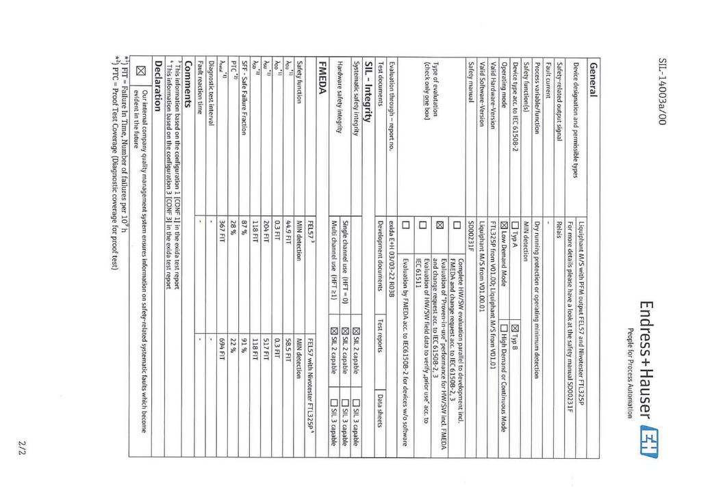
Functional safety manual Liquiphant M/S with FEL57 and Nivotester FTL325P
|
|
|
- Camilla Porter
- 5 years ago
- Views:
Transcription
1 T T SD00231F/00/EN/ Products Solutions Services Functional safety manual Liquiphant M/S with FEL57 and Nivotester FTL325P [Ex ia] [Ex ia] FTL325N FTL325N CH2 CH3 CH2 CH3 Level Limit Measuring System Application Dry running protection or operating minimum detection of all types of liquids in tanks to satisfy particular safety systems requirements as per IEC The measuring device fulfills the requirements concerning Safety functions up to SIL 2 Explosion protection by means of intrinsic safety EMC to EN and NAMUR Recommendation NE 21. Your benefits For minimum detection up to SIL 2 Independently assessed (Functional Assessment) by exida.com as per IEC Permanent automatic monitoring No calibration Insensitive to external vibration Easy commissioning Space-saving switching unit Testing of the measuring system at the push of a button Fail-safety by means of PFM technology
2 Table of contents SIL declaration of conformity Introduction Structure of the measuring system Level limit measuring system Safety function Permitted device types Safety function data Supplementary device documentation Settings and installation instructions Installation instructions Response in operation and failure Repair Recurrent function tests of the measuring system. 11 Failure rates of electrical components Appendix Specific values and wiring options for the measuring system Exida Management Summary Endress+Hauser
3 SIL declaration of conformity SIL06005a Endress+Hauser 3
4 SIL06005a 4 Endress+Hauser
5 Introduction General information about Functional Safety (SIL) can be obtained at: and in the competence brochure CP01008Z/11/EN "Functional safety in the Process Industry risk reduction with Safety Instrumented Systems" Structure of the measuring system Level limit measuring system The measuring system's devices are displayed in the following diagram (example). A B 1 2 [Ex ia] T FTL325 [Ex ia] FTL325 T CH2 CH3 CH2 CH3 1 FEL - Electronic insert A Nivotester FTL325P (One-channel) 2 Liquiphant M/S B Nivotester FTL325P (Three-channel) A Safety function The safety-related signal of the measuring system is the level relay of the Nivotester. All safety functions refer exclusively to this signal. The safety function applies to settings in MIN safety (dry running protection) and use of the NO contacts of the level relays. The MIN safety setting has the effect that the level relay always works in quiescent current safety; i.e. the relay opens if: The switch point is undershot (level is below response height) A fault occurs The power supply voltage fails In addition to the level relay, the alarm relay works in operating current safety and closes the contact if: One of the following faults occurs: the sensor connection is interrupted the sensor connection short circuits the corrosion alarm of the sensor is triggered An internal error is detected The power supply voltage fails The measuring range of the Liquiphant M/S is dependent on the installation site and fork length. The detection range is located within the fork length and is dependent on the density of the medium. Alternative measures must be taken during device configuration and maintenance work on the Liquiphant M/S + Nivotester FTL325P to guarantee process safety. Endress+Hauser 5
6 The following settings are permitted for the safety function: Device Setting As-delivered state Liquiphant Density switch setting: 0,7 Density switch setting: 0,7 Nivotester FTL325P-#3#3 Nivotester FTL325P-#1#1 Test mode "EXT" MIN safety All settings except " S function" (see section "Settings and installation instructions") MIN safety One-channel operation Test mode "STD" MAX safety Three-channel operation MAX safety One-channel operation When the alarm relay releases, the level relay also releases. The alarm relay is not part of the safety function! Permitted device types The details pertaining to functional safety in this manual relate to the device versions listed below and are valid as of the specified firmware and hardware version. Unless otherwise specified, all subsequent versions can also be used for safety instrumented systems. A modification process according to IEC is applied for device changes. Valid device versions for safety-related use: Liquiphant M FTL50, FTL50H, FTL51, FTL51C, FTL51H Feature Designation Option model 010 Approval all 020 Process connection all 030 Probe length; Type all 040 Electronics; Output 7 FEL57; SIL 2-wire PFM 050 Housing; Cable entry all 060 Additional options all Valid firmware version: as of Valid hardware version (electronics): as of Valid device versions for safety-related use: Liquiphant S FTL70, FTL71 Feature Designation Option model 010 Approval all 020 Process connection all 030 Probe length all 040 Electronics; Output 7 FEL57; SIL 2-wire PFM 050 Housing; Cable entry all 060 Additional option all 070 Application all Valid firmware version: as of Valid hardware version (electronics): as of Endress+Hauser
7 Valid device versions for safety-related use: Nivotester FTL325P Feature Designation Option model 010 Approval G H N P T W ATEX II 3(G Ex nc/a (ia) IIC T4, SIL, IECEx Zone 2 ATEX II (GD (Ex ia) IIC, WHG, SIL, IECEx (Ex ia) IIC (Liquiphant M / Liquiphant S) NEPSI (Ex ia) IIC, SIL (Liquiphant M / Liquiphant S) FM IS Cl. I, II, III Div. 1 Gr. A-G, SIL (Liquiphant M / Liquiphant S) CSA IS Cl. I, II, III Div. 1 Gr. A-G, SIL (Liquiphant M / Liquiphant S) TIIS Ex ia IIC, SIL, labeling in Japan 020 Housing all 030 Power Supply all 040 Switch output all Valid hardware version (electronics): as of Safety function data Please note that the safety-related signal of the measuring system is not available until 60 s after the power supply voltage for the safety function has been switched on. The mandatory settings and data for the safety function can be found in the Appendix ( ä 12). In the case of watery media, the reaction time of the measuring system is s. MTTR is set at eight hours. Safety systems without a self-locking function must be monitored or set to an otherwise safe state after carrying out the safety function within MTTR. Endress+Hauser 7
8 Supplementary device documentation Liquiphant M FTL50, FTL50H, FTL51, FTL51H, FTL51C Documentation Contents Comment Technical Information FTL50, FTL50H, FTL51, FTL51H: TI00328F/00/EN FTL51C: TI00347F/00/EN Operating Instructions FTL50, FTL51: KA00143F/00/A6 KA00163F/00/A6 FTL50H, FTL51H: KA00144F/00/A6 KA00164F/00/A6 ) FTL51C: KA00162F/00/A6 KA00165F/00/A6 ) Safety instructions depending on the selected version "Approval" Technical data Accessories Installation Wiring Operation Commissioning Troubleshooting Repair Maintenance Safety, installation and operating instructions for devices, which are suitable for use in potentially explosive atmospheres or as overfill protection (WHG, German Water Resources Act). The documentation is available on the Internet: The documentation is supplied with the device. The documentation is also available on the Internet: Additional safety instructions (XA, ZE) are supplied with certified device versions. Please refer to the nameplate for the relevant safety instructions. with aluminium housing / separate terminal compartment. Liquiphant S FTL70, FTL71 Documentation Contents Comment Technical Information TI00354F/00/EN Operating Instructions KA00172F/00/A6 KA00173F/00/A6 Safety instructions depending on the selected version "Approval" Technical data Accessories Installation Wiring Operation Commissioning Troubleshooting Repair Maintenance Safety, installation and operating instructions for devices, which are suitable for use in potentially explosive atmospheres or as overfill protection (WHG, German Water Resources Act). The documentation is available on the Internet: The documentation is supplied with the device. The documentation is also available on the Internet: Additional safety instructions (XA, ZE) are supplied with certified device versions. Please refer to the nameplate for the relevant safety instructions. with aluminium housing / separate terminal compartment 8 Endress+Hauser
9 Nivotester FTL325P Documentation Contents Comment Technical Information TI00350F/00/EN Operating Instructions One-channel device: KA00167F/00/A6 Three-channel device: KA00168F/00/A6 Safety instructions depending on the selected version "Approval" Technical data Accessories Installation Wiring Operation Commissioning Troubleshooting Repair Maintenance Safety, installation and operating instructions for devices, which are suitable for use in potentially explosive atmospheres or as overfill protection (WHG, German Water Resources Act). The documentation is available on the Internet: The documentation is supplied with the device. The documentation is also available on the Internet: Additional safety instructions (XA, ZE) are supplied with certified device versions. Please refer to the nameplate for the relevant safety instructions. Endress+Hauser 9
10 Settings and installation instructions Installation instructions Please refer to the Operating Instructions (BA) for information regarding the correct installation of the. Since the application conditions have an effect on the safety of the measurement, pay attention to the notes in the Technical Information (TI) and Operating Instructions (BA). The ambient conditions for the Nivotester FTL325P must correspond to IP54 (in accordance with EN 60529). The manuals on setting the devices can be found in the section "Supplementary device documentation", ä 8. Settings for electronic insert FEL57 For SIL 2 operation, the following settings are mandatory for the electronic insert FEL57: Recurrent function test setting = EXT Setting for density switch = 0,7 After commissioning the measuring system, changes to the settings at the electronic insert FEL57 can impair the safety function! The SIL evaluation of the Liquiphant M/S comprises the entire device including electronic insert, tuning fork with drive, process connection and internal wiring. Settings for Nivotester FTL325P-#3#3 (three-channel version) It is recommended that the shift elements following the dry running protection be left in a safe state after responding until the alarm signal has been acknowledged. Setting Description " Caution! CH2 Channel 2+3 in S function This setting is not permitted for the safety function! s CH3 A CH3 CH2 s Channel 1, independent Channel 2+3 in S function Channel 1 is permitted for the safety function! Channels 2 and 3 in this setting are not permitted for the safety function! A Observe the following for the Nivotester FTL325P: The operator must use suitable measures (e.g. current limiter, fuse) to ensure the relay contact characteristics are not exceeded: U 253 V AC 50/60 Hz, I 2 A, P 500 VA at cos 0,7 or U 40 V DC, I 2 A, P 80 W Changes to the measuring system and its settings after commissioning can impair the safety function! 10 Endress+Hauser
11 Response in operation and failure The response in operation and failure is descriped in the documentation, which can be found in the section "Supplementary device documentation", ä 8. Repair In the event of failure of a SIL-labeled Endress+Hauser device, which has been operated in a protection function, the "Declaration of Contamination and Cleaning" with the corresponding note "Used as SIL device in protection system" must be enclosed when the defective device is returned Recurrent function tests of the measuring system Liquiphant M/S Nivotester Test Setting for density switch Setting for test mode Setting Test interval Description of the test procedure Setting 0,7 EXT Every permitted setting and fault message -> ON when channel 1 is connected to a sensor Function test with test button; annually Complete function test, e.g. approaching the level; after 5 years at the latest KA167F/00/A6 KA168F/00/A6 The operativeness of the dry running protection must be checked periodically if the PFD avg values given in the Appendix are used. The check must be carried out in such a way that it is proven that the dry running protection functions perfectly in interaction with all components. This is guaranteed if the response height is approached in a draining process. If it is not practical to drain until the response height is reached, suitable simulation of the level must be used to make the level sensor respond e.g. through the use of a lockable bypass. If the operativeness of the level sensor/transmitter can be determined otherwise (exclusion of faults that impair function), the check can also be completed by simulating the corresponding output signal. Note the following points for the function test: Every channel must be tested individually by pressing the respective test key. Relay contact switching must be checked electrically, e.g. using a hand multimeter at the terminals. In multi-channel instruments, all channels which do not carry out a safety function must be included in the recurrent function tests if faulty functioning cannot be detected by any other means. As a positive test result, the system reaction must correspond to the specified description. If the system reaction does not correspond to the described procedure, the monitored process must be set to a safe state by means of additional or other measures and/or kept in the safe state until the safety system is repaired. Failure rates of electrical components The underlying failure rates of electrical components apply within the usable service life IEC Section Note 3 Endress+Hauser 11
12 Appendix Specific values and wiring options for the measuring system The tables show the specific values and wiring options for the measuring system. Note the following points on the tables below: A common cause factor = 5% has been assumed for the calculations specified below. The PFD avg values for multi-channel systems already contain common cause failures for the associated wiring scheme. The PFD avg values are only valid for the associated wiring scheme. They are not suitable for deducing calculations for other wiring schemes. Using NC contacts instead of NO contacts requires further consideration of the installation means. The wiring scheme shows the number of instruments (Liquiphant and Nivotester) and the limit relay contact circuits (open, when the Liquiphant signals covering). With several instruments in a wiring scheme, they all indicate the same displayed settings. The tables show safety-relevant values and wiring options for the measuring system. FIT = Failure in Time, 1 FIT = /h For safety related use of the Liquiphant M/S for MIN detection, the following application errors must be excluded: Permanent and/or heavy build-up or "non-newtonian media" Solid proportions of the medium with a diameter > 5,0 mm (0.2 in) Corrosion: The Liquiphant may only be used in media to which the process-wetted parts are resistant. If coated sensors are used, measures must therefore be taken to ensure that there is no damage during installation and operation. The errors may cause that the demand mode of the safety function is not detected and the Liquiphant will not switch as intended. 12 Endress+Hauser
13 Liquiphant M/S - Setting Density 0,7 1oo1 architecture [CONF 2] Nivotester FTL325P-#1#1 Setting (One-channel device) MIN fail safe mode A SIL SIL 2 HFT 0 SFF 91% PFD avg (low demand mode of operation) sd su dd du MTBF Wiring scheme 0,024 x FIT 457 FIT 0,3 FIT 56 FIT 133 years A Function test with test button Complete function test, e.g. approaching the level annually after 5 years at the latest Source: Management summary of the exida.com test report (see appendix). Probability 3,00E-03 1oo1 structure 2,50E-03 2,00E-03 1,50E-03 1,00E-03 5,00E-04 0,00E Years *1 *2 *1 without annual function test with test button *2 with annual function test with test button A EN Endress+Hauser 13
14 Liquiphant M/S - Setting Density 0,7 1oo1 architecture [CONF 3] Nivotester FTL325P-#3#3 Setting (Three-channel device) MIN fail safe mode A SIL SIL 2 HFT 0 SFF 91% PFD avg (low demand mode of operation) sd su dd du MTBF Wiring scheme 0,025 x FIT 517 FIT 0,3 FIT 59 FIT 122 years CH2 CH3 CH2, CH3: A Function test with test button Complete function test, e.g. approaching the level annually after 5 years at the latest Source: Management summary of the exida.com test report (see appendix). Probability 1oo1 structure 3,00E-03 2,50E-03 2,00E-03 1,50E-03 1,00E-03 5,00E-04 0,00E Years *1 *2 *1 without annual function test with test button *2 with annual function test with test button A EN 14 Endress+Hauser
15 Liquiphant M/S - Setting Density 0,7 1oo1 architecture [CONF 4] Nivotester FTL325P-#3#3 Setting (Three-channel device) MIN fail safe mode CH3 s CH2 A SIL SIL 2 HFT 0 SFF 91% PFD avg (low demand mode of operation) sd su dd du MTBF 0,024 x FIT 457 FIT 0,3 FIT 56 FIT 133 years Wiring scheme SIL : CH2 CH3 Function test with test button annually A Complete function test, e.g. approaching the level after 5 years at the latest Source: Management summary of the exida.com test report (see appendix). Probability 3,00E-03 1oo1 structure 2,50E-03 2,00E-03 1,50E-03 1,00E-03 5,00E-04 0,00E Years *1 *2 *1 without annual function test with test button *2 with annual function test with test button A EN Endress+Hauser 15

16 Exida Management Summary Exida Management Summary 2 Exida Management Summary 1 16 Endress+Hauser

17 Exida Management Summary 4 Exida Management Summary 4 Endress+Hauser 17
18 18 Endress+Hauser
19 Endress+Hauser 19
20
Liquiphant S, Nivotester FDL60/61, FTL670
 Functional Safety Manual Liquiphant S, Nivotester FDL60/61, FTL670 Level limit measuring system FTL670 s Application Overfill protection or maximum detection of all types of liquids, to meet the particular
Soliphant M with electronic insert FEM52
 Functional safety manual Soliphant M with electronic insert FEM52 Level Limit Measuring System Application Overfill protection or operating maximum detection of all types of solids in tanks to satisfy
Proservo NMS5- / NMS7-
 Functional Safety Manual Proservo NMS5- / NMS7- Tank gauge for Liquid level measurement with 4 to 20mA Output or with Alarm Relay Contact Output Application Operating minimum (e.g. dry run protection),
Differential Pressure Transmitter deltabar S PMD 230/235 deltabar S FMD 230/630/633 with ma output signal
 Safety Manual SD 158P/00/en Differential Pressure Transmitter deltabar S PMD 230/235 deltabar S FMD 230/630/633 with 4...20 ma output signal Functional safety manual Application Overspill protection or
Functional Safety Manual Oil Leak Detector NAR300 System
 SD01357G/08/EN/01.14 71255416 Products Solutions Services Functional Safety Manual Oil Leak Detector NAR300 System Application This system is designed to be installed in a pit, dike, plant, or sump pit
Pressure Transmitter cerabar S PMC 731/631 cerabar S PMP 731/635 with ma output signal
 Safety Manual SD 159P/00/en Pressure Transmitter cerabar S PMC 731/631 cerabar S PMP 731/635 with 4...20 ma output signal Functional safety manual Application Pressure measurements (e.g. limit pressure
Pressure Transmitter cerabar M PMC 41/45 cerabar M PMP 41/45/46/48 with Output Signal ma/hart
 Safety Manual SD 172P/00/en 71036063 Pressure Transmitter cerabar M PMC 41/45 cerabar M PMP 41/45/46/48 with Output Signal 4...20 ma/hart Functional Safety Manual Application Pressure measurement (e.g.
Deltapilot S FMB70. Functional Safety Manual. Level and Pressure Measurement with Output Signal ma
 Functional Safety Manual Deltapilot S FMB70 Level and Pressure Measurement with Output Signal 4...20 ma Application Use for process pressure measurement in aggressive and non-aggressive gases, vapours
Cerabar S PMC71, PMP71, PMP75
 Functional Safety Manual Cerabar S PMC71, PMP71, PMP75 Process Pressure and Level Measurement with Output Signal 4...20 ma Application Use for process pressure measurement (e.g. limit pressure monitoring)
Proof Testing Level Instruments
 Proof Testing Level Instruments Partial proof testing of level instruments can save millions of dollars while maintaining required safety ratings By Bill Sholette, Level Product Business Manager Endress+Hauser
Functional Safety Manual June pointek CLS500/LC500
 Functional Safety Manual June 2009 pointek CLS500/LC500 Introduction 1 Level Switch Pointek CLS500 SITRANS LC500 SIL Safety Manual Supplement to device manual General safety instructions 2 Device-specific
Rod probe 11961Z. Technical Information. Conductive level limit detection Partially insulated rod probe for use in conductive liquids
 Technical Information Rod probe 11961Z Conductive level limit detection Partially insulated rod probe for use in conductive liquids Application Conductive level limit detection in process or storage tanks
Safety in the process industry
 Products Solutions Services Safety in the process industry Simply reliable Table of contents Endress+Hauser: At home in the process safety Smart devices and concepts for hazardous areas Introduction to
FUNCTIONAL SAFETY MANUAL
 FUNCTIONAL SAFETY MANUAL UltraSonic EX-5 Ultrasonic Gas Leak Detector The information and technical data disclosed in this document may be used and disseminated only for the purposes and to the extent
FUNCTIONAL SAFETY MANUAL
 f u n c t i o n a l S a f e t y M a n u a l FUNCTIONAL SAFETY MANUAL Gassonic Surveyor and Gassonic Observer Ultrasonic Gas Leak Detectors The information and technical data disclosed in this document
Gammapilot M FMG60. Functional safety manual. Radiometric measurement technology Maximum point level detection
 Functional safety manual Gammapilot M FMG60 Radiometric measurement technology Maximum point level detection Application Overfill protection or maximum point level detection of all types of liquids and
Technical Manual for the Manual Alarm Call Point BG
 Technical Manual for the Manual Alarm Call Point BG Please note that every care has been taken to ensure the accuracy of our technical manual. We do not, however, accept responsibility for damage, loss
PPA Michaël GROSSI - FSCE PR electronics
 Functional Safety Component selection according to IEC61511 Title 2 Presentation Michaël GROSSI: Ex / SIL Product manager @ Degree in Instrumentation & Measurement More than 10 years experience in Functional
Failure Modes, Effects and Diagnostic Analysis. PR electronics A/S Rønde Denmark
 Failure Modes, Effects and Diagnostic Analysis Project: 9203 Solenoid / Alarm Driver Customer: PR electronics A/S Rønde Denmark Contract No.: PR electronics 06/03-19 Report No.: PR electronics 06/03-19
Products Solutions Services. Safety by Design. Ask questions, get answers! Slide 1 06/15/2017. Ngo
 Products Solutions Services Safety by Design Ask questions, get answers! Slide 1 Hai-Thuy Industry Manager Oil & Gas Slide 2 Since 2005 working for Endress+Hauser Hai-Thuy Slide 3 Functional Safety Professional
SAFETY MANUAL. Intelligent Sensors for H 2 S Gas Applications
 SAFETY MANUAL Intelligent Sensors for H 2 S Gas Applications The information and technical data disclosed in this document may be used and disseminated only for the purposes and to the extent specifically
FUNCTIONAL SAFETY MANUAL. Gassonic Observer-H and Observer-i Ultrasonic Gas Leak Detector
 FUNCTIONAL SAFETY MANUAL Gassonic Observer-H and Observer-i Ultrasonic Gas Leak Detector The information and technical data disclosed in this document may be used and disseminated only for the purposes
Ultrasonic Level Measurement nivopuls FDU 10 S
 Technical Information TI 275F/00/en Ultrasonic Level Measurement nivopuls FDU 10 S Level limit switch for liquids with separate electronics unit Non-contact from outside Suitable for use in explosion hazardous
SITRANS. Temperature transmitter Functional safety for SITRANS TW. Introduction. General safety instructions 2. Device-specific safety instructions
 Introduction 1 General safety instructions 2 SITRANS Temperature transmitter Device-specific safety instructions 3 Appendix List of Abbreviations/Acronyms A B Product Information Supplement to Operating
Liquiphant T FTL20H. Technical Information
 Technical Information Liquiphant T FTL0H Level limit switch for liquids in the foodstuff industry, compact design, housing made of corrosion-resistant stainless steel Application The Liquiphant T FTL0H
Technical Data. General specifications Switching element function Rated operating distance s n 5 mm
 0102 Model Number Features 5 mm flush Usable up to SIL 3 acc. to IEC 61508 Application Danger! In safety-related applications the sensor must be operated with a qualified fail safe interface from Pepperl+Fuchs,
Operating Manual MS220KA and MSR220KA
 Temperature Relays and MINIKA, Mains Monitoring, Digital Panel meters MINIPAN, Switching Relays and Controls Operating Manual MS220KA and MSR220KA ZIEHL industrie elektronik GmbH + Co KG Daimlerstraße
SAFETY MANUAL. IR5000 Open Path Hydrocarbon Gas Monitoring System
 SAFETY MANUAL Open Path Hydrocarbon Gas Monitoring System The information and technical data disclosed in this document may be used and disseminated only for the purposes and to the extent specifically
Simply reliable: Process safety from Endress+Hauser
 Products Solutions Services Simply reliable: Process safety from Endress+Hauser Safety by choice, not by chance: Functional Safety Slide 1 Oil & Gas industry Hai-Thuy Industry Manager Oil & Gas Slide 2
The Liquiphant family Point level detection in liquids using the vibronic measuring principle
 Level Products Solutions Services The Liquiphant family Point level detection in liquids using the vibronic measuring principle 2 Liquiphant Family Innovation with a superb background Liquiphant, the original
Manual Power relay SR853
 Manual Power relay SR853 Product types SR853.8.x.x, Rev. 1 SR853 manual page2 The symbols WARNING, CAUTION, NOTE This symbol warns of a serious hazard. Failure to observe this warning may result in death
SAFETY MANUAL. PointWatch Eclipse Infrared Hydrocarbon Gas Detector Safety Certified Model PIRECL
 SAFETY MANUAL PointWatch Eclipse Infrared Hydrocarbon Gas Detector SIL 2 Certified Model PIRECL Safety Certified Model PIRECL PointWatch Eclipse IR Gas Detector This manual addresses the specific requirements
SAFETY MANUAL. Electrochemical Gas Detector GT3000 Series Includes Transmitter (GTX) with H 2 S or O 2 Sensor Module (GTS)
 with H 2 S or O 2 Sensor Module (GTS)") SAFETY MANUAL Electrochemical Gas Detector GT3000 Series Includes Transmitter (GTX) with H 2 S or O 2 Sensor Module (GTS) Sensor Module (GTS) Transmitter (GTX) Detector (GT3000) SAFETY CERTIFIED GT3000
SAFETY MANUAL Electrochemical Gas Detector GT3000 Series Includes Transmitter (GTX) with H 2 S or O 2 Sensor Module (GTS) Sensor Module (GTS) Transmitter (GTX) Detector (GT3000) SAFETY CERTIFIED GT3000
Operating Manual MS220DA
 ZIEHL industrie elektronik GmbH + Co KG Daimlerstraße 13, D 74523 Schwäbisch Hall + 49 791 504-0, info@ziehl.de, www.ziehl.de Temperature Relays and MINIKA Mains Monitoring Digital Panel Meters MINIPAN
Introduction. Additional information. Additional instructions for IEC compliant devices. Measurement made easy
 ABB MEASUREMENT & ANALYTICS SIL-SAFETY MANUAL TTH300, TTF300 Temperature transmitter Additional instructions for IEC 61508 compliant devices Measurement made easy TTH300 TTF300 Introduction TTH300, TTF300
IECEx Certificate of Conformity
 INTERNATIONAL ELECTROTECHNICAL COMMISSION IEC Certification Scheme for Explosive Atmospheres for rules and details of the IECEx Scheme visit www.iecex.com issue No.:3 Status: Current Date of Issue: 2010-10-04
SAFETY MANUAL. Multispectrum IR Flame Detector X3301
 SAFETY MANUAL Multispectrum IR Flame Detector X3301 SAFETY-CERTIFIED MODEL X3301 MULTISPECTRUM INFRARED DETECTOR This manual addresses the specific requirements and recommendations applicable to the proper
Failure Modes, Effects and Diagnostic Analysis
 Failure Modes, Effects and Diagnostic Analysis Project: Detcon FP-700 Combustible Gas Sensor Customer: Detcon The Woodlands, TX USA Contract No.: DC 06/08-04 Report No.: DC 06/08-04 R001 Version V1, Revision
Technical Data. Dimensions
 0102 Model Number Features 5 mm flush Usable up to SIL2 acc. to IEC 61508 Accessories EXG-18 Quick mounting bracket with dead stop BF 18 Mounting flange, 18 mm Technical Data specifications Switching element
SAFETY MANUAL. FL4000H and FL4000 Multi-Spectral Infrared Flame Detectors
 SAFETY MANUAL FL4000H and FL4000 Multi-Spectral Infrared Flame Detectors The information and technical data disclosed in this document may be used and disseminated only for the purposes and to the extent
Technical Data. Dimensions
 0102 Model Number Features 15 mm non-flush Technical Data specifications Switching element function NAMUR, NC Rated operating distance s n 15 mm Installation non-flush Assured operating distance s a 0...
Snifter ATEX22 VERSION. User Manual. Distributor
 Snifter ATEX22 VERSION User Manual Distributor Version 1.4 09/09/2009 Table of Contents 1. INTRODUCTION... 3 1.1. Safety... 3 1.2. Product overview... 4 1.3. How does it work?... 4 2. INSTALLATION... 5
1510 Side Mounted Level Switch
 1510 Side Mounted Level Switch General Instructions The SOR 1510 Level Switch mounts into the side of a vessel. Electric switching action is provided by the float moving a magnet into the field of a hermetically
Inductive slot sensor
 0102 Model Number Features 2 mm slot width Technical Data specifications Switching function Normally closed (NC) Output type NAMUR Slot width 2 mm Depth of immersion (lateral) 5... 7 mm, typ. 6 mm Output
IECEx Certificate of Conformity
 IECEx Certificate of Conformity INTERNATIONAL ELECTROTECHNICAL COMMISSION IEC Certification Scheme for Explosive Atmospheres for rules and details of the IECEx Scheme visit www.iecex.com issue No.:1 Status:
SECTION INDUCTIVE CONDUCTIVITY ANALYZERS
 SECTION 40 75 16 INDUCTIVE CONDUCTIVITY ANALYZERS PART 1 General 1.01 SUMMARY A. Requirements for a digital inductive conductivity sensor for standard, hazardous and hightemperature applications. The sensor
FMEDA Report. Failure Modes, Effects and Diagnostic Analysis. KFD0-CS-Ex*.54* and KFD0-CS-Ex*.56* Project: X7300
 Failure Modes, Effects and Diagnostic Analysis Device Designation: KFD0-CS-Ex*.54* and KFD0-CS-Ex*.56* Project: X7300 Pepperl+Fuchs GmbH Mannheim Germany Mannheim norm sheet 1 of 16 Released EDM checkout
Technical Data. Dimensions
 0102 Model Number Features Comfort series 50 mm non-flush Technical Data specifications Switching element function NAMUR, NC Rated operating distance s n 50 mm Installation non-flush Output polarity NAMUR
FMEDA and Proven-in-use Assessment. Pepperl+Fuchs GmbH Mannheim Germany
 FMEDA and Proven-in-use Assessment Project: Transmitter Supply Isolators KF**-CRG-*** Customer: Pepperl+Fuchs GmbH Mannheim Germany Contract No.: P+F 02/11-01 Report No.: P+F 02/11-01 R012 Version V2,
GESTRA Steam Systems NRS English. Installation Instructions Level Switch NRS 1-51
 GESTRA Steam Systems NRS 1-51 EN English Installation Instructions 818955-04 Level Switch NRS 1-51 1 Contents Application Page Usage for the intended purpose...4 Function...4 Directives and Standards Pressure
SAFETY MANUAL. X2200 UV, X9800 IR, X5200 UVIR SIL 2 Certified Flame Detectors
 SAFETY MANUAL X2200 UV, X9800 IR, X5200 UVIR SIL 2 Certified Flame Detectors SAFETY-CERTIFIED Flame DETECTORs This manual addresses the specific requirements and recommendations applicable to the proper
Technical Data. General specifications Switching element function Rated operating distance s n 4 mm
 0102 Model Number Features 4 mm non-flush Accessories BF 12 Mounting flange, 12 mm Technical Data specifications Switching element function NAMUR, NO Rated operating distance s n 4 mm Installation non-flush
Guidelines. Safety Integrity Level - SIL - Valves and valve actuators. February Valves
 Valves Guidelines Safety Integrity Level - SIL - Valves and valve actuators February 2009 VDMA German Engineering Federation Valves Manufacturers Association Chairman: Prof.-Dr.-Ing. Heinfried Hoffmann
Failure Modes, Effects and Diagnostic Analysis
 Failure Modes, Effects and Diagnostic Analysis Project: Mobrey 2130 Vibrating Fork Point Level Switch Company: Mobrey Measurement SLOUGH, SL1 4UE UK Contract Numbers: Mobrey Q08/08-57 and Q11/05-090 Report
SIL Safety Guide Series MS Single-Acting Spring-Return Hydraulic Linear Actuators
 SIL Safety Guide Series MS Single-Acting Spring-Return Hydraulic Linear Actuators Rev 0, November 17 2015 Page 1 of 9 Table of Contents 1 INTRODUCTION 3 1.1 Terms and abbreviations 3 1.2 Acronyms 4 1.3
United Electric Controls One Series Safety Transmitter Safety Manual
 United Electric Controls One Series Safety Transmitter Safety Manual OneST-SM-02 1 INTRODUCTION This Safety Manual provides information necessary to design, install, verify and maintain a Safety Instrumented
HAWK Measurement Systems Pty. Ltd. Centurion CGR Series Safety Manual
 HAWK Measurement Systems Pty. Ltd. Centurion CGR Series Safety Manual Document No. SIL0008 Version 1.7 17/04/2018 1. Revision History: Revision Author Reviewed Approved Update Details Date 0.1 Klaus Lorentschitsch
Operating Guide Safe Torque Off
 ENGINEERING TOMORROW Operating Guide Safe Torque Off VLT Frequency Converters vlt-drives.danfoss.com Contents Operating Guide Contents 1 Introduction 2 1.1 Purpose of the Manual 2 1.2 Additional Resources
Safety Temperature Limiter STL 50 Certified to DIN EN (replaces DIN 3440)
") Safety Temperature Limiter STL 50 Certified to DIN EN 14597 (replaces DIN 3440) Features M For use as: STB Protection - temperature limiter ASTB Exhaust gas - protection - temperature limiter STW Protection
Safety Temperature Limiter STL 50 Certified to DIN EN 14597 (replaces DIN 3440) Features M For use as: STB Protection - temperature limiter ASTB Exhaust gas - protection - temperature limiter STW Protection
Technical Manual for the Horn - DB1PUL DB1HP UL
 Technical Manual for the Horn - DB1PUL DB1HP UL Please note that every care has been taken to ensure the accuracy of our technical manual. We do not, however, accept responsibility for damage, loss or
Technical Data. Dimensions
 0102 Model Number Features 8 mm non-flush Stainless steel housing Usable up to SIL2 acc. to IEC 61508 Technical Data specifications Switching element function NAMUR, NC Rated operating distance s n 8 mm
Technical Data. General specifications Switching element function Rated operating distance s n 8 mm
 0102 Model Number Features 8 mm non-flush Usable up to SIL 3 acc. to IEC 61508 Application Danger! In safety-related applications the sensor must be operated with a qualified fail safe interface from Pepperl+Fuchs,
Failure Modes, Effects and Diagnostic Analysis
 Failure Modes, Effects and Diagnostic Analysis Project: Oldham OLCT 200 Transmitter Company: Industrial Scientific Corporation Oakdale, PA USA Contract Number: Q11/05-009 Report No.: IS 10/10-010 R001
SIPART. Electropneumatic positioner Functional safety for SIPART PS2. Introduction. General safety instructions 2. Device-specific safety instructions
 Introduction 1 General safety instructions 2 SIPART Electropneumatic positioner Device-specific safety instructions 3 Appendix List of Abbreviations/Acronyms A B Product Information Supplement to the manuals
Technical Data. General specifications Switching element function Rated operating distance s n 5 mm
 0102 Model Number Features 5 mm non-flush Usable up to SIL2 acc. to IEC 61508 Technical Data specifications Switching element function NAMUR, NC Rated operating distance s n 5 mm Installation non-flush
GMA200-MW4. User Manual. Gas detection controller for wall mounting
 User Manual GMA200-MW4 Gas detection controller for wall mounting GfG GESELLSCHAFT FÜR GERÄTEBAU MBH KLÖNNESTRASSE 99 44143 DORTMUND, GERMANY TEL. +49 / (0)231 / 564 00 0 FAX +49 / (0)231 / 516 313 INFO@GFG-MBH.COM
Technical Manual for the Strobe - SM87 HXB
 Technical Manual for the Strobe - SM87 HXB Please note that every care has been taken to ensure the accuracy of our technical manual. We do not, however, accept responsibility for damage, loss or expense
FUNCTIONAL SAFETY OF ELECTRICAL INSTALLATIONS IN INDUSTRIAL PLANTS BY OTTO WALCH
 FUNCTIONAL SAFETY OF ELECTRICAL INSTALLATIONS IN INDUSTRIAL PLANTS BY OTTO WALCH Troublefree and safe operation of industrial systems is of great importance, not only for the safety of the systems and
itemp RTD TMT 187 itemp TC TMT 188 Temperature head transmitter
 BA 104R/24/ae/10.03 itemp RTD TMT 187 itemp TC TMT 188 Temperature head transmitter Operating instructions RTD TC TMT 187 TMT 188 Temperature head transmitter Safety message # Warning! Instructions and
100 & 120 Series Pressure and Temperature Switches Safety Manual
 100 & 120 Series Pressure and Temperature Switches Safety Manual MECH-SM-01 1 INTRODUCTION This Safety Manual provides information necessary to design, install, verify and maintain a Safety Instrumented
Failure Modes, Effects and Diagnostic Analysis
 Failure Modes, Effects and Diagnostic Analysis Project: Type 95IR/95UV/95DS Flame Scanners Customer: FIREYE Derry, New Hampshire USA Contract No.: FIR 04/08-21 Report No.: FIR 04/08-21 R002 Version V1,
Safety instrumented systems
 Safety instrumented systems SIL2 / SIL3 rated vibronic point level measurement devices for overfill protection Typical tank farm Liquid level limit detection switch Liquiphant Chemical plant A white paper
OPTIBAR DP 7060 Supplementary Instructions
 OPTIBAR DP 7060 Supplementary Instructions Differential pressure transmitter Category ATEX II 1/2G, 2G Ex db ia IIC T6...T1 Ga/Gb, Gb IECEx Ex db ia IIC T6...T1 Ga/Gb, Gb Housing Aluminium: Single chamber,
Functional Safety Manual Cerabar M PMC51, PMP51/55 Deltabar M PMD55 Deltapilot M FMB50/51/52/53
 SD00347P/00/EN/03.16 71344568 Products Solutions Services Functional Safety Manual Cerabar M PMC51, PMP51/55 Deltabar M PMD55 Deltapilot M FMB50/51/52/53 Process pressure / Differential pressure, Flow
SAFETY CERTIFIED MODEL FP-700 COMBUSTIBLE GAS DETECTOR
 SAFETY MANUAL SIL 2 Certified Model FP-700 Combustible Hydrocarbon Gas Sensor Version 2.0 1 SAFETY CERTIFIED MODEL FP-700 COMBUSTIBLE GAS DETECTOR This manual addresses the specific requirements and recommendations
How E+H instrumentation can improve process safety
 Products Solutions Services How E+H instrumentation can improve process safety With special focus on Coriolis flowmeters Slide 1 Scope of presentation Slide 2 What is safety? Is this safety? Slide 3 Safety
Operating Guide Safe Torque Off
 ENGINEERING TOMORROW Operating Guide Safe Torque Off VLT Frequency Converters vlt-drives.danfoss.com Contents Operating Guide Contents 1 Introduction 2 1.1 Purpose of the Manual 2 1.2 Additional Resources
Session Ten Achieving Compliance in Hardware Fault Tolerance
 Session Ten Achieving Compliance in Hardware Fault Tolerance Mirek Generowicz FS Senior Expert (TÜV Rheinland #183/12) Engineering Manager, I&E Systems Pty Ltd Abstract The functional safety standards
Engineering Guideline. pac-carriers Type for TRICON system TRICONEX TMR PLC
 Engineering Guideline pac-carriers Type 9195 for TRICON system TRICONEX TMR PLC 2 Engineering Guideline TRICON system 14.10.2009 Content Signal type Control system I/O cards type pac-carrier Channels Slots
Rosemount Functional Safety Manual. Manual Supplement , Rev AF March 2015
 Rosemount 2120 Functional Safety Manual Manual Supplement Manual Supplement Contents Contents 1Section 1: Introduction 1.1 Scope and purpose of the safety manual.................................. 1 1.2
ProcessMaster FEP300, FEP500 HygienicMaster FEH300, FEH500 Electromagnetic Flowmeter
 SIL-Safety Instructions SM/FEX300/FEX500/SIL-EN Rev. C ProcessMaster FEP300, FEP500 HygienicMaster FEH300, FEH500 Electromagnetic Flowmeter Information about functional safety Measurement made easy Change
Failure Modes, Effects and Diagnostic Analysis
 Failure Modes, Effects and Diagnostic Analysis Project: Phoenix Type 85UVF/IRF Flame Scanner Company: FIREYE Derry, New Hampshire USA Contract Number: Q08/04-57 Report No.: FIR 08/04-57 R001 Version V2,
Technical Data. General specifications. Rated operating distance s n 5 mm
 0102 Model Number Features 5 mm non-flush Usable up to SIL 2 acc. to IEC 61508 Technical Data specifications Switching function Normally closed (NC) Output type NAMUR Rated operating distance s n 5 mm
Failure Modes, Effects and Diagnostic Analysis. Rosemount Inc. Chanhassen, Minnesota USA
 Failure Modes, Effects and Diagnostic Analysis Project: 2088 Pressure Transmitter Customer: Rosemount Inc. Chanhassen, Minnesota USA Contract No.: ROS 06/10-18 Report No.: ROS 06/10-18 R001 Version V1,
Failure Modes, Effects and Diagnostic Analysis
 Failure Modes, Effects and Diagnostic Analysis Project: Fireye Flame Sensor Module CE Flameswitch, model MBCE-110/230FR Company: Fireye Derry, NH USA Contract Number: Q09/10-26 Report No.: FIR 09/10-26
Regulated Ex-Heater HEX with internal controller, HEX with external controller II 3 G II 3 D
 Regulated Ex-Heater HEX5-1.08 with internal controller, HEX5-2.08 with external controller II 3 G II 3 D Instruction Manual Version 1.02.00 Dear customer, we have made up this operating manual in such
... RD0-TI-Ex8.FF.* Temperature Multi-Input Device for Cabinet Installation. Features. Assembly. Function. Connection. Zone 1
 emperature Multi-Input Device for Cabinet Installation Features Assembly For 8 temperature or analog sensors Installation in Zone 1/Div. 1, intrinsically safe Sensors in Zone 0/Div. 1 Connection to fieldbus
FUNCTIONAL SAFETY CERTIFICATE
 FUNCTIONAL SAFETY CERTIFICATE This is to certify that the X5000 & S5000 Fixed Gas Detector Range MSA The Safety Company manufactured by General Monitors 1000 Cranberry Woods Drive 26776 Simpatica Cir Cranberry
OilSET Installation and Operating Instructions. Oil Separator Alarm Device with SET/DM3AL sensor
 Labkotec UK Ltd Adminicle House 1 Lumb Lane Audenshaw Manchester M34 5WH GREAT BRITAIN Tel: 0844 3350 477 Fax: 0161 4281 179 E-mail: info@labkotec.co.uk 10.8.2012 Internet: www.labkotec.co.uk 1/13 OilSET-1000
Advanced Diagnostic Gateway with Ethernet and FF-H1 Interface and I/O. Assembly
 Advanced Diagnostic Gateway with Ethernet and FF-H1 Interface and I/O Features Assembly System integration kit for Advanced Diagnostics PCS integration via Diagnostic Manager or device DTM Simple automatic
Vibracon LVL-A* Level limit switch for liquids, compact design
 Technical Information TI 364O/98/en/.07 8905 /07 0 Vibracon LVL-A* Level limit switch for liquids, compact design Application The Vibracon LVL-A* is a level limit switch for all kinds of fluids and is
Functional Safety Solutions
 Demand Moore Reliability IEC 61508/61511 Solutions Line Card Functional Safety Solutions for Your Safety Instrumented System www.miinet.com Functional Safety Products Designed and Built for your Process
SET Installation and Operating Instructions. Level switch for one sensor
 Labkotec Oy Myllyhaantie 6 FI-33960 PIRKKALA FINLAND Tel.: +358 29 006 260 Fax: +358 29 006 1260 7.11.2013 Internet: www.labkotec.fi 1/14 SET-1000 Level switch for one sensor Copyright 2013 Labkotec Oy
Certification Supplement Manual
 PROCESS ANALYSERS SERVOTOUGH FluegasExact (2700) Gas Analyser Certification Supplement Manual Part Number: 02700008D Revision: 2 Language: UK English Blank CONTENTS 1 INTRODUCTION 2 EC DECLARATION OF CONFORMITY
USB Interface for setup program. 1 analog output standard signal. LCD display with white background lighting. 1 relay output pre-alarm ( KV)
") Data Sheet 701155 Page 1/19 JUMO safetym STB/STW Ex Safety Temperature Limiter/Monitor According to DIN EN 14597 and ATEX Approval Brief description The compact and user configurable JUMO safetym STB/STW
Data Sheet 701155 Page 1/19 JUMO safetym STB/STW Ex Safety Temperature Limiter/Monitor According to DIN EN 14597 and ATEX Approval Brief description The compact and user configurable JUMO safetym STB/STW
Safety instructions VEGAPULS 64
 Safety instructions Intrinsic safety "i" 4 20 ma/hart - two-wire Document ID: 53001 Contents 1 Area of applicability... 3 2 Important specification in the type code... 3 3 Different ignition protection
MANUAL Overflow sensor NVF-104/34-PF
 PROCESS AUTOMATION MANUAL Overflow sensor NVF-104/34-PF ISO9001 0102 Overflow sensor NVF-104/34-PF With regard to the supply of products, the current issue of the following document is applicable: The
OMC Ex interface unit. Manual. Version 1.2 August Author: Observator Instruments
 OMC-158-2 Ex interface unit Manual Version 1.2 August 2017 Author: Observator Instruments Revisions: 0.1 (October 2016) First issue 0.2 (December 2016) Prototype 0.3 (January 2017) Test release 1.0 (March
Certification Supplement Manual
 SERVOTOUGH FluegasExact (2700) Gas Analyser Certification Supplement Manual Part Number: 02700008D Revision: 5 Language: UK English Blank CONTENTS 1 INTRODUCTION 2 EU DECLARATION OF CONFORMITY 3 EUROPEAN
Tech days Edmonton. Next Level Instrumentation. Products Solutions Services. By Ing. Rob Vermeulen, Bec
 Products Solutions Services Tech days Edmonton Next Level Instrumentation By Ing. Rob Vermeulen, Bec By Gerhard Jansson, Application Support Level + Pressure at SC-CA Slide 1 Why do we need to go to the