SENSORS CATALOGUE TEMPERATURE MEASUREMENT IN INDUSTRIAL ENVIRONMENTS
|
|
|
- Ophelia Annabel Hicks
- 5 years ago
- Views:
Transcription


1 SENSORS CATALOGUE TEMPERATURE MEASUREMENT IN INDUSTRIAL ENVIRONMENTS


2 SENSORS FOR EXPLOSIVE ATMOSPHERES 174 SENSORS CATALOGUE

3 REMINDERS CONCERNING THE ATEX DIRECTIVE 176 PRESSURE EQUIPMENT DIRECTIVE 180 OPERATING SAFETY (SIL) 180 GAS ENVIRONMENT A - ZONES 0, 1, 2 - ID50: Ex ia SENSOR TA1G: Ex ia TC SENSOR SA1G: Ex ia Pt100 SENSOR TCG3i: Ex ia TC WITH CABLE TCG32i: Ex ia TC WITH CABLE S1i: Ex ia PT100 WITH CABLE. 208 B - ZONES 1, 2 - ID50: Ex d SENSOR. 210 DUST ENVIRONMENT 222. A - ZONES 20, 21, 22 - TA1D: Ex ia TC SENSOR. - SA1D: Ex ia Pt100 SENSOR TCG3i: Ex ia TC WITH PVC CABLE TCG32i: Ex ia TC WITH PVC CABLE S1i: Ex ia PT100 WITH CABLE 232 B - ZONES 21, 22 - TA2D: Ex d TC SENSOR SA2D: Ex d PT100 SENSOR. 236 OTHER ATEX d & ia SENSORS A- SKIN SENSOR (SEE PAGE 150) B- AMBIENT TEMPERATURE SENSOR (SEE PAGES 160 TO 164) C- HIGH-PRESSURE SENSOR (SEE PAGE 268) D- BEARING SENSOR (SEE PAGE 298) SENSORS CATALOGUE 175
4 SENSORS FOR EXPLOSIVE ENVIRONMENTS ATEX DIRECTIVE A - THE ATEX 2014/34/EU DIRECTIVE EX An explosive atmosphere (ATEX) is a mixture, in atmospheric conditions, of inflammable substances in gas, vapour or dust form with air, in which, after inflammation, combustion propagates to the whole of the unburned mixture. Ignition source 1 - GLOSSARY Explosive atmosphere: Defined as a mixture of inflammable substances in gas, vapour, mist or dust form With air; In atmospheric conditions; In which, after inflammation, combustion propagates to the whole of the unburned mixture. Explosible atmosphere: Atmosphere liable to become explosive. Ignition source: Inherent to the equipment concerned, a specific feature whose activation constitutes a risk of ignition. A distinction must be made between these two concepts during risk analysis. The possible ignition sources are listed in EN On a site transforming combustible materials, and in the presence of oxygen in the ambient air, the ignition source is the only element which can easily be eliminated to prevent an explosion. 13 ignition sources are identified in EN Products in suspension (gas, aerosols, dust) EXPLOSION Explosive range Normal operation: Situation which exists when the equipment, protective systems and components fulfil their planned function in the context of their design parameters. Small leaks may be part of normal operation. Failures requiring repairs or shutdown are not considered to be part of normal operation. Combustible material Confinement Oxygen Directive 2014/34/EU, which is a revision of directive 94/9/CE, was published in the official bulletin of the European Union on 29th March It has been mandatory since 20th April The texts for transposition into French law have been published: Decree no of 1st July 2015 concerning hazardous products and equipment Decree of 1st July 2015 concerning organizations authorized to perform conformity assessments and in-service monitoring operations on hazardous products and equipment Directive 2014/34/EU applies equally to electrical and mechanical equipment. It explicitly covers the instruments and protective systems used in an ATEX atmosphere, as well as the safety, control and adjustment systems, even if they are not in contact with an ATEX atmosphere, as long as they are necessary for or contribute to operation on instruments and protective systems. Temperature measurements in explosive zones are covered by this directive. Dysfunction: Situation which exists when the equipment, protective systems and components do not fulfil their planned function and may generate an ignition source. A foreseeable dysfunction is one which we know through experience may occur during the product s life span. A rare dysfunction only occurs exceptionally. 2 - DETERMINATION OF THE ZONES The site manager is responsible for classification of the zones in which an ATEX atmosphere may form. This classification depends on the probability of ATEX atmosphere formation and determines the category of equipment installed there. The equipment manufacturer is not responsible for imposing the right equipment category, but it has a duty to inform its customers of the applicable regulations. The zones are defined according to the type and the probability of it encountering such an atmosphere. There are 3 levels of classification for ATEX zones, depending on the clearance for the source of combustible material and the type of ventilation in place. A distinction is made between zones containing gas or vapour and zones where dust is present. 176 SENSORS CATALOGUE
5 SENSORS FOR EXPLOSIVE ENVIRONMENTS ATEX DIRECTIVE Zone 0 Zone 1 Zone 2 Zone 20 Zone 21 Zone 22 GASES / VAPOURS / MISTS Explosive atmosphere present continuously or for long periods in normal operation hours/year = constant, long-term or frequent hazard Explosive atmosphere present occasionally in normal operation Between 10 and 100 hours/year or more = occasional hazard Explosive atmosphere present accidentally, in the event of dysfunction or for short periods Less than 10 hours/year = rare or short-term hazard DUSTS Explosive atmosphere present continuously or for long periods in normal operation hours/year = constant, long-term or frequent hazard Explosive atmosphere present occasionally in normal operation Between 10 and 100 hours/year or more = occasional hazard Explosive atmosphere present accidentally, in the event of dysfunction or for short periods Less than 10 hours/year = rare or short-term hazard Category 2: The anti-explosion protective systems for equipment in this category must operate in a way that ensures a sufficient level of protection against explosion risks even in the event of foreseeable dysfunctions. This equipment is designed to operate in zones 1 or 21. Category 3: The design of the equipment in this category must ensure a sufficient level of anti-explosion protection in normal operation. This equipment is designed to operate in zones 2 or 22. The equipment categories in Group II should be used as follows: G : Gas D : Dust ZONE EQUIPMENT CATEGORY 0 1G, (1)G 1 2G, (2)G (or 1G, (1)G) 3 - GROUPS OF GASES AND DUSTS En the ATEX framework, a reference gas corresponds to each group of gases. These groups are based on their ignition characteristics. GROUP REFERENCE GAS GAS DANGER LEVEL IIA Propane ++ IIB Ethylene +++ IIC (the most dangerous) Hydrogen/Acetylene ++++ Dusts are also classified in 3 groups of explosible gases. GROUP TYPE OF DUST DUST DANGER LEVEL IIIA Combustible fibres + IIIB Non-conductive dust ++ IIC (the most dangerous) Conductive dust DEFINITION OF THE EQUIPMENT CATEGORIES GROUPS I AND II The equipment and protective systems are divided into two groups: Group I : equipment intended for use in the underground and surface parts of mines which may be endangered by firedamp and/or inflammable dust. Group II : equipment intended for use in surface industries which may be endangered by explosible atmospheres. We do not propose any products classified in Group I. We will therefore only deal with equipment in Group II. CATEGORIES IN GROUP II Category 1: Equipment in this category is characterized by at least two protective systems against explosion risks, operating in such a way that, if one of the protective systems fails, at least one independent secondary system ensures sufficient protection. This equipment is designed to operate in zones 0 or G, (3)G (or 1G and 2G, (1)G and (2)G) 20 1D, (1)D 21 2D, (2)D (or 1D, (1)D) 22 3D, (3)D (or 1D and 2D, (1)D and (2)D) Use in the hazardous zone: Category 1G Installation in safe zone. Transmits or receives a signal from to the hazardous zone: Category (1)G If you wish to use equipment in zone 0, its category must be 1G. Only this category is authorized in this zone. For zone 2, equipment in Category 3G is authorized, along with equipment in Categories 1G and 2G: what can do more can also do less. Equipment in the xgd categories can be used in explosible Gas and Dust atmospheres. 5 - TEMPERATURE CLASSES Below, we present the different ATEX temperature classes, applicable to ATEX atmospheres, with limitation rules which differ according to the temperatures. These temperature ranges (T1 to T6) can then be used to classify the equipment intended for installation or use in ATEX zones. The self-ignition temperature indicated for a combustible product (gas, vapour, dust) is the temperature at which the mixture with air spontaneously ignites. There is no need to provide a specific ignition source (flame, spark, electric arc, etc.) because the temperature is sufficient to set fire to the mixture. Manufacturers commit to a temperature for their equipment by means of the temperature classes. If the equipment is in temperature class T2, the manufacturer guarantees that the surface temperature of its equipment will never exceed 300 C in the conditions indicated. The maximum admissible surface temperature must always be lower than the self-ignition point. SENSORS CATALOGUE 177
6 SENSORS FOR EXPLOSIVE ENVIRONMENTS ATEX DIRECTIVE TEMPERATURE CLASSES Maximum admissible surface Equipment marking temperature 450 C T1 300 C T2 200 C T3 135 C T4 100 C T5 85 C T6 TABLE SUMMARIZING THE CORRESPONDENCE BETWEEN GAS GROUPS AND TEMPERATURE CLASSES: I II A CLASSIFICATION OF GASES AND VAPOURS IN GAS GROUPS AND TEMPERATURE CLASSES T1 T2 T3 T4 T6 Methane Acetone, ethane, ethyl acetate, ammoniac, benzol, acetic acid, carbon monoxide, methanol, propane, toluene Ethyl alcohol, i-amyl acetate, n-butane, n-butyl alcohol Gasoline, diesel oil, kerosene, domestic fuel oil, n-hexane Acetic acid, ether II B City gas Ethylene II C Hydrogen Acetylene Carbon disulphide TEMPERATURE LIMITATION RULES For dusts: the temperature is part of the Ex Dust marking. Dust clouds: If a dust cloud occurs, the maximum surface temperature of the equipment must not exceed 2/3 of the ignition temperature under any circumstances: Max. temperature (C ) = 2/3 of the ignition temperature of a dust cloud (Tci) Dust layers: The temperature must be limited if there is a layer of dust present less than 5 mm thick: Max. temperature = 5 mm 75 k (75 k is the safety coefficient equal to 75 C) EXAMPLES OF EXPLOSIBLE DUSTS Acetylsalicylic acid, ascorbic acid, aluminium, starch (wheat), asphalt, wheat, cocoa, cellulose, flour / bread wheat, powdered milk, malt, paracetamol, polystyrene, soap, soya (flour), sugar, etc. NOTES On DUST-certified ATEX products, the maximum surface temperature is indicated in plain language in the Dust marking on the label. This should not be confused with the temperature class (T1 to T6) which only concerns gases and vapours! Do not confuse the maximum surface temperature of dust-certified equipment (e.g. T85 C ) or the temperature class of gas-certified equipment (e.g. T4 ) with the admissible ambient temperature for the equipment. These are distinct characteristics. IFA / INRS IDENTIFICATION NO. SELF-IGNITION TEMPERATURE T1 DUST CLOUD EQUIPMENT SURFACE TEMPERATURE (2/3 OF T1) SELF-IGNITION TEMPERATURE T2 5 MM DUST LAYER EQUIPMENT SURFACE TEMPERATURE (T2-75 C) MAX. SURFACE TEMPERATURE TO USE WHEN CHOOSING THE EQUIPMENT Wheat in bulk C 326 C 290 C 215 C 215 C Cocoa powder C 393 C 250 C 175 C 175 C Wheat starch C 253 C 530 C 455 C 253 C Powdered milk C 306 C 330 C 255 C 255 C Soya flour C 286 C 420 C 345 C 286 C Sulphur C 160 C 250 C 175 C 160 C Charcoal C 346 C 320 C 245 C 245 C Sugar, pectin C 273 C 380 C 305 C 273 C Source: GESTIS-CARATEX databank 178 SENSORS CATALOGUE
7 SENSORS FOR EXPLOSIVE ENVIRONMENTS ATEX DIRECTIVE 6 - PROTECTION MODES There are several protection modes recognized by the IEC (International Electrotechnical Commission) and CENELEC (Comité Européen de Normalisation Electrotechnique / European Committee for Electrotechnical Standardization). Each protection mode is symbolized by lower-case letters which figure on the equipment s ATEX label. Several protection modes may be used on the same equipment. If so, the symbols concerned are indicated one after the other (e.g. Ex db eb op is q IIC T4 Gb). The most widely-used protection modes for Pyrocontrole s temperature sensors are ia (intrinsic safety) and d (explosionproof enclosure). MAIN PROTECTION MODES FOR ELECTRICAL EQUIPMENT TYPE SYMBOL PROTECTION MODE GROUP d EQUIPMENT CATEGORY EQUIPMENT PROTECTION LEVEL (EPL) da 1 G Ga db explosion-proof enclosure II 2 G Gb dc 3 G Gc CENELEC / IEC STANDARDS PRINCIPLE OF PROTECTION Parts which may ignite an explosive atmosphere are enclosed in an enclosure which must withstand an internal explosion and prevent propagation of the explosion outside it. e i eb 2 G Gb increased safety II ec 2 D Db ia 1 G Ga ib intrinsic safety II 2 G Gb Steps are taken from the design phase onwards to avoid any internal overheating and any electric arcs or sparks inside or on the external parts of electrical equipment. Limitation of electrical energy and internal heating, thus preventing any ignition. ic 3 G Gc na na non-sparking II 3 G Gc Elimination of electric arcs, sparks and internal heating. nc nc sealed unit II 3 G Gc nr nr limited respiration II 3 G Ga m op is t ma 1 G Gb mb encapsulated II 2 G Gb mc 3 G Gc op is 1 G Ga op is optical radiation with intrinsic safety II 2 G Gb op is 3 G Gc ta 1 D Da tb protection by enclosure III 2 D Db tc 3 D Dc Must contain any internal explosion or must prevent the explosive mixture from penetrating inside. Enclosure designed to limit penetration of the explosive mixture. Exclusion of the explosive atmosphere by encapsulation of the parts in resin. Limitation of the light energy produced (e.g. by a LED), to avoid ignition of the surrounding explosive atmosphere. The construction of the equipment prevents any penetration inside by dust. 7 - PROTECTION RATINGS IP INGRESS PROTECTION RATINGS (IEC 60529) SOLID PARTICLE PROTECTION LIQUID INGRESS PROTECTION 0 Not protection. 1 Protected against solid bodies larger than 50 mm. Example: involuntary contact with hand. Protection against dripping water (vertically-falling drops). Example: condensation. 2 Protected against solid bodies larger than 12.5 mm. Example: finger. Protected against dripping water when the enclosure is tilted by up to (15 ). 3 Protected against solid bodies larger than 2.5 mm. Example: tools, wires. Protected against dripping water when the enclosure is tilted by up to Protected against solid bodies larger than 1 mm. Example: small tools, small wires. Protected against water splashing from any direction. 5 Protected against dust. No harmful deposit. Protected against water projected by a nozzle from any direction. 6 Protected against penetration by dust (dust-tight). Protected against water projected in powerful jets similar to heavy sea spray. 7 Protected against the effects of immersion at depths between 0.15 and 1 m. 8 Protected against the effects of prolonged immersion under pressure. SENSORS CATALOGUE 179
8 SENSORS FOR EXPLOSIVE ATMOSPHERES PED / SIL 8 - COMPLETE ATEX MARKING LCIE 14ATEX3020X Notified body Year of certification ATEX certification Certification number Special conditions of use indicated in the certificate 0081 II 1G Ex ia IIC Ga T4 T6 Regulatory marking ATEX product Category ATEX product Equipment group Equipment protection level Number of notified body Equipment group Environment (in this case: Gas) Protection mode Gas group Temperature class B - DIRECTIVE NO. 2014/68/EU PRESSURE EQUIPMENT The European Pressure Equipment Directive (PED) specifies the requirements concerning pressure equipment for the distribution of pressure equipment inside the European economic area. The version currently in force is directive 2014/68/EU of the European Parliament and Council of 15th May 2014 regarding harmonization of the legislation in the member states concerning the commercialization of pressure equipment. After examining the datasheets from the Pressure Equipment Liaison Committee (CLAP) concerning Directive 2014/68/EU, PYROCONTROLE can inform you that: An isolated sensor does not meet the definition of a pressure accessory (Guideline number A-25 CLAP number X029) If a sensor is considered to be a component incorporated in an item of equipment, the requirements must be checked but the marking is not applicable (Guideline number A-22 CLAP number X027) The compliance assessment procedures and the essential safety requirements in PED 97/23/CE are applicable to the whole safety chain (Guideline number A-25 CLAP number X029) Consequently, CE marking cannot be placed on an isolated sensor (in the context of the Pressure Equipment Directive). C - SIL (SAFETY INTEGRITY LEVEL) EN STANDARD This standard covers the functional safety of electrical/electronic/ programmable electronic systems related to safety. It concerns applications for which a failure of these systems has a significant effect on the safety of people, the environment and the installations. 180 SENSORS CATALOGUE
9 SENSORS FOR EXPLOSIVE ATMOSPHERES SIL THE EN STANDARD: Some industrial processes may represent a hazard for people, the environment and the installations themselves. The safety functions are intended to reduce these hazards. SIL involves reducing the risks to a tolerable level. The EN standard was published to describe both the type of risk assessment necessary and the development of safety functions for the sensors, the logical processing part and the actuators. These measures include risk suppression (systematic faults) and risk control (random faults). This basic standard, which is independent of the applications, describes the requirements regarding the safety functions of the components and systems, allowing the development of branch-specific standards (e.g. the EN standard: see below). THE EN STANDARD: This international standard can be used to define the requirements concerning the specifications, design, installation, operation and maintenance of an instrumented safety system, so that it can be implemented with total confidence, thus establishing and/or maintaining the safety of the process at an acceptable level. This standard was designed to constitute an implementation of IEC in process industries. PYROCONTROLE proposes SIL Capable process sensors by using temperature transmitters compliant with the EN standard. The performance level may be: SIL 2 Capable or SIL 3 Capable, depending on the type of mounting. SENSORS CATALOGUE 181
10 GAS ENVIRONMENT 182 SENSORS CATALOGUE
11 ZONES 0, 1, 2 SENSORS CATALOGUE 183


12 SENSORS FOR EXPLOSIVE ENVIRONMENTS GAS ZONE PYROmodules id50, a modular solution for the configuration and maintenance of Atex temperature sensors dedicated to temperature measurement Thanks to a wide choice of references, the PYROmodules id50 system allows you to define a tailored Atex ia/d sensor adapted to your in-line temperature measurement application. For maintenance of your sensors, the id50 system enables you to replace the faulty part(s) only, whatever the sensor brand, at a competitive price. ADVANTAGES OF ID50 GUARANTEED SAFETY The id50 modules system offers numerous protective measures guaranteeing a high level of safety. +Atex certification is maintained, even in the event of partial replacement of an existing sensor + All the thermowells are the subject of calculation notes in accordance with the ASME PTC TW 2016 standard + All the equipment is SILcertified* *for any assembly with a TTH200/ TTH300 transmitter 184 SENSORS CATALOGUE


 / welded Double weld Full-penetration welded Machined in rough forging ID50")

13 SENSORS FOR EXPLOSIVE ENVIRONMENTS GAS ZONE ID50 MODULES TAILORED CONSTRUCTION With this smart modular solution, you can assemble your Atex ia/d temperature sensor to suit the specific features of your application. Numerous references are available. Indicators Transmitters TTH200/ TTH300 Single / Duplex Type AS Type A Type AS Type A TTH200/ TTH200 TTH300 TTH300 TTH Screwed ceramic Single Duplex Single / terminal block Duplex 2, 4 or 6 terminals Duplex Single TTH200/ TTH300 Single / Duplex Heads LSX-W - with window 2 tube support LSX-W - with window Wall bracket LSX-W - with window Output M20x1.5 G1/2 LSX-D - without window Output M20x1,5 G1/2 Other Atex head id50 Measuring elements 3-wire Pt100, K, J or N TCs, single or duplex Length 380 to 650 mm Thermowells id50 Upper extension id50 id50 Upper extension Lower extension See page 238 PCV PCB-VS 1 1/2 flange - class 150 to 600 PCB-2S 1 1/2 flange - class 150 to 600 PCB-PP 1 1/2 flange - class 150 to 1,500 PCB-F 1 1/2 flange - class 150 to 1,500 PCB-F 2 flange - class 2,500 Screwed Screwed (NPT) / welded Double weld Full-penetration welded Machined in rough forging ID50 MODULES SIMPLIFIED MAINTENANCE WORK With the id50, modules, change only the faulty part(s) of your sensor and reduce your maintenance costs. +This innovative modular system allows you to replace only the damaged parts +Atex certification maintained id50 system ADAPTABLE to ALL TYPES and MAKES of Atex sensors for temperature measurement SENSORS CATALOGUE 185


14 SENSORS FOR EXPLOSIVE ATMOSPHERES GAS ZONES 0, 1, 2 ID50 COMPLETE ASSEMBLED SENSOR IP 54 IEC OR IEC60751 Ex ia and Ex d up to 1150 C DESCRIPTION id50 sensor delivered complete and assembled. This sensor comprises the components detailed in the pages which follow. The section presenting the thermowells begins on page 238. SPECIFICATIONS See following pages. Cable gland not supplied. See page 184 for an overview of the Pyromodules id50 solution. 186 SENSORS CATALOGUE
15 SENSORS FOR EXPLOSIVE ATMOSPHERES GAS ZONES 0, 1, 2 DESIGN YOUR SENSOR CONFIGURATOR CODE Parameters to be indicated when ordering MODEL ELEMENT TERMINAL STRIP / TRANSMITTER DISPLAY ATEX LENGTH L1 (mm) TRANSMITTER SCALE ID Reference in table and diagram Possible choice Pt100 2Pt100 1TCK 2TCK 1TCJ 2TCJ 1TCN 2TCN Ceramic terminal strip: B TTH200 T200 TTH300: T300 LC5335: 5335 Without: XS AS: AS A: AA d: AD ia: IA DIAGRAM DISPLAY Transmitter type Indicator type TTH200 TTH300 Type AS: without keypad Type A: with keypad 3 ATEX PROTECTION MODES 4 ATEX zone ia protection mode d protection mode LENGTH L1 The length L1 should be determined according to the depth of the thermowell (P1), as shown in the table below 5 Sensing element length P1 min. (mm) P1 max. (mm) SENSORS CATALOGUE 187
16 SENSORS FOR EXPLOSIVE ATMOSPHERES GAS ZONES 0, 1, 2 LSX-D / LSX-W HEADS IP 54 WITH OR WITHOUT WINDOW INTRINSIC SAFETY DESCRIPTION ATEX heads for the id50 system. The PYROmodules id50 solution gives you the choice between an LSX-W head with a window and an LSX-D head without a window SPECIFICATIONS Model LSX-D LSX-W ATEX II 1 GD / Ex ia IIC T6 Material Epoxy-coated aluminium alloy Colour Yellow Cable input (cable gland, not supplied) Window for mounting a display External earth terminal Cover chain Accessory supplied 1 input M20x1.5 with plastic cover 1 input M20x1.5 with plastic cover 1 input M20x1.5 with cap Sleeved base for locking the internal element, reference L SENSORS CATALOGUE
17 SENSORS FOR EXPLOSIVE ATMOSPHERES GAS ZONES 0, 1, 2 DESIGN YOUR SENSOR HEAD INDICATOR TRANSMITTER EXTENSIONS SENSING ELEMENT CODES FOR ORDERS MOUNTING Photo Head ATEX Pyrocontrole code LSX-D: without window ia L LSX-W: with window ia L LSX-W with strap for 2" tube ia L LSX-W with wall bracket ia L SENSORS CATALOGUE 189

18 SENSORS FOR EXPLOSIVE ATMOSPHERES GAS ZONES 0, 1, 2 AS - A INDICATORS WITH OR WITHOUT KEYPAD INTRINSIC SAFETY SELF- POWERED DESCRIPTION ATEX ia indicators for the id50 system. LCD indicators for mounting on TTH transmitters Type AS: without keypad Type A: with keypad SPECIFICATIONS Model Type AS Type A Reference L L Properties Graphical LCD indicator controlled by transmitter without configuration function Graphical LCD indicator controlled by transmitter with configuration function (keypad) Compatibility TTH200 / TTH300 TTH300 Display Display possibilities Ambient operating temperature Polarity signs, 4 digits, 2 digits after decimal point Sensor process value Bar chart Output % Height of characters depending on the mode, polarity signs, 4 digits, 2 digits after the decimal point, graphical bar indicator. Sensor 1 process value Sensor 2 process value Ambient temp./ electronics temp. Output value Output % Bar chart Output % Troubleshooting display information for transmitter and sensor status -20 to +70 C 190 SENSORS CATALOGUE
19 SENSORS FOR EXPLOSIVE ATMOSPHERES GAS ZONES 0, 1, 2 DESIGN YOUR SENSOR HEAD INDICATOR TRANSMITTER EXTENSIONS SENSING ELEMENT DISPLAY Type A LCD indicator Type AS LCD indicator MOUNTING The type A indicator can only be mounted on a TTH300 transmitter. The type AS indicator can be mounted on a TTH200 or TTH300 transmitter. It can be configured using the keypad on the indicator. The indicator is fixed on a tilted base. The indicator+transmitter assembly can only be mounted in LSX-W heads Quit / Cancel 2 Scroll back 3 Scroll forward 4 Confirm CODES FOR ORDERS Indicator type Type AS: without keypad Type A: with keypad Transmitter type TTH200 TTH300 Atex Pyrocontrole code ia L ia L SENSORS CATALOGUE 191
20 SENSORS FOR EXPLOSIVE ATMOSPHERES GAS ZONES 0, 1, TTH200/300 TRANSMITTERS INSULATED 4-20 ma OUTPUT TTH300 DUPLEX VERSION TTH200 TTH300 IP20 / IP IP68 / IP00 UNIVERSAL INPUT HART DESCRIPTION Programmable transmitters for conversion into a 4-20 ma analogue signal TRANSMITTER SPECIFICATIONS Model TTH200 TTH Reference LTTH LTTH LC5335B-100 ATEX Compatible protection mode Ambient operating temperature II 1 G Eex ia IIC T6 II 2(1)G Eex [ia] ib IIC T6 II 2 G (1D) Ex [iad] ib IIC T6 II 1 G Ex ia IIC T6 Ga II 2(1)G Ex [ia] ib IIC T6 Gb (Ga) II 2 G (1D) Ex [iad] ib IIC T6 Gb (Da) Ex ia -50 to +44 C for T6 / -40 to +60 C for T4 II 1 G Ex ia IIC T6 or T4 Ga -40 to +60 C for T6-40 to +85 C for T4 HART protocol HART 5 HART 5 or HART 7 (choice by switch) Delivered with HART 5 HART 5 as standard. Input 3 or 4-wire Pt100 / J, K, N or T TC Cold junction compensation (if used as TC input) Number of sensors Output 4-20mA Sensor breakage Programmable mA Power supply 11 30Vdc Vdc Galvanic insulation 3.5 kvdc (2,5 kvac), 60s 1.5 kvac / 50Vac Protection rating (as per EN60529) (head/ terminals) IP20 / IP00 IP68 / IP00 Dimensions Diam 44.4mm x h 24.7mm Diam 44.0mm x h 20.2mm TERMINAL STRIP SPECIFICATIONS References L L L Number of terminals Connection 1 x TC 2 x TC or 1 x 3-wire Pt100 2 x 3-wire Pt SENSORS CATALOGUE
21 SENSORS FOR EXPLOSIVE ATMOSPHERES GAS ZONES 0, 1, 2 DESIGN YOUR SENSOR HEAD INDICATOR TRANSMITTER EXTENSIONS SENSING ELEMENT CONNECTION TTH200/300 transmitter MOUNTING Insert the wires of the ID50 measuring element inside the transmitter and screw it inside the connecting head. For the intrinsic-safety loop calculation, the electrical parameters of the transmitters are indicated in the ia/a safety instructions. Set up the cable of the ID50 measuring element as shown in the wiring diagrams transmitter CODES FOR ORDERS Transmitter ATEX Pyrocontrole code TTH200 ia LTTH TTH300 ia LTTH B ia LC5335B-100 Ceramic terminal strip ATEX Pyrocontrole code 2 terminals ia L terminals ia L terminals ia L Compatibility SENSORS CATALOGUE 193
22 SENSORS FOR EXPLOSIVE ATMOSPHERES GAS ZONES 0, 1, 2 ID50 SENSOR EXTENSIONS ADJUSTABLE FROM 120 TO 200 MM STAINLESS STEEL 316L DESCRIPTION The extension provides the link between the head and the thermowell. It comprises two parts, upper and lower, and can be adjusted without cutting according to the length of the measuring element and the depth of the thermowell. SPECIFICATIONS Part Upper Lower ATEX II 2G - Ex db IIC T6 Gb N/A Material 316L Mounting On head On thermowell Threading As per table opposite 1/2 NPT Accessories Screw for locking the measuring element for any head other than the LSX model. Thread lock. 194 SENSORS CATALOGUE
23 SENSORS FOR EXPLOSIVE ATMOSPHERES GAS ZONES 0, 1, 2 DESIGN YOUR SENSOR HEAD INDICATOR TRANSMITTER EXTENSIONS SENSING ELEMENT DIAGRAM MOUNTING Set the upper extension in place on the thermowell. Screw the lower extension on the thermowell with a size-27 openend wrench by making use of the hexagonal shape of the leak-tight fitting. ` Tighten until the lower extension is locked. CODES FOR ORDERS Assembly F Pyrocontrole code For LSX head (locking screw not included) G1/2 L Upper extension G1/2 L G12 for other heads M24 L M24 (screw included) M20 L M20 1/2 NPT L N12 Lower extension L SENSORS CATALOGUE 195
24 SENSORS FOR EXPLOSIVE ATMOSPHERES GAS ZONES 0, 1, 2 IDG50 THERMOCOUPLE INTRINSIC SAFETY CLASS 1 SINGLE OR DUPLEX IEC up to 1100 C DESCRIPTION Thermocouple measuring elements for the id50 system. SPECIFICATIONS Model idg50 Compliance with standards IEC / IEC / EN ATEX II 2 G / Ex db IIC T6 Gb / II 1 GD / Ex ia IIC T6 Ga / Ex ia IIIC T85 C Da Type K J N Material Inconel L Inconel 600 Class Diameter (d) (mm) 6 Hot junction Thermocouple Insulated Single / Duplex Lengths (mm) 200 to 1000 Operating Min temperature ( C) Max Output Wires 150 mm long with end-pieces Vibration withstand 60g 196 SENSORS CATALOGUE
25 SENSORS FOR EXPLOSIVE ATMOSPHERES GAS ZONES 0, 1, 2 DESIGN YOUR SENSOR HEAD INDICATOR TRANSMITTER EXTENSIONS SENSING ELEMENT DIAGRAM DETERMINATION OF THE LENGTH OF THE IDG50 ELEMENT Flanged thermowell CODES FOR ORDERS K THERMOCOUPLE Single reference Duplex reference Length 200 mm L L Length 250 mm L L Length 300 mm L L Length 350 mm L L Length 400 mm L L Length 450 mm L L Length 500 mm L L Length 550 mm L L Length 600 mm L L Length 650 mm L L Length 700 mm L L Length 750 mm L L Length 800 mm L L Length 850 mm L L Length 900 mm L L Length 950 mm L L Length 1000 mm L L N thermocouple L L J thermocouple L L By determining dimension P1 (drilling depth of the thermowell), you can choose the length of the ID50 measuring element. This length can be determined using a measuring rod. The lengths of the sensing elements according to the depth P1 are defined in the table below. *measuring rod = Reference = L CONNECTIONS - SINGLE AND DUPLEX K TC Duplex K TC Green + Green Green + - Sensing element length Min. P1 (mm) Max. P1 (mm) SENSORS CATALOGUE 197
26 SENSORS FOR EXPLOSIVE ATMOSPHERES GAS ZONES 0, 1, 2 IDG50 Pt100 INTRINSIC SAFETY CLASS A SINGLE OR DUPLEX IEC up to 450 C DESCRIPTION Pt100 measuring elements for the id50 system SPECIFICATIONS Model idg50 Compliance with standards IEC / EN ATEX II 2 G / Ex db IIC T6 Gb / II 1 GD / Ex ia IIC T6 Ga / Ex ia IIIC T85 C Da Type Pt100 Material 316 L Class A Diameter (d) (mm) 6 Min./max. operating temp. ( C) -40 C 450 C Output Wires 150 mm long with end-pieces Reference L L L L Thermocouple Single Duplex Single Duplex Mounting 1x3 wires 2x3 wires 1x3 wires 2x3 wires Vibration withstand 10g 50g See page 184 for an overview of the PYROmodules id50 solution 198 SENSORS CATALOGUE
27 SENSORS FOR EXPLOSIVE ATMOSPHERES GAS ZONES 0, 1, 2 DESIGN YOUR SENSOR HEAD INDICATOR TRANSMITTER EXTENSIONS SENSING ELEMENT DIAGRAM DETERMINATION OF THE LENGTH OF THE IDG50 SENSING ELEMENT Flanged thermowell CODES FOR ORDERS 3-wire Pt100, Withstand 10g Single reference Duplex reference Length 200 mm L L Length 250 mm L L Length 300 mm L L Length 350 mm L L Length 400 mm L L Length 450 mm L L Length 500 mm L L Length 550 mm L L Length 600 mm L L Length 650 mm L L Length 700 mm L L Length 750 mm L L Length 800 mm L L Length 850 mm L L Length 900 mm L L Length 950 mm L L Length 1000 mm L L wire Pt100, Withstand 50g L L By determining dimension P1 (drilling depth of the thermowell), you can choose the length of the ID50 measuring element. This length can be determined using a measuring rod. The lengths of the sensing elements according to the depth P1 are defined in the table below. CONNECTIONS Connection 1 Pt100 Ω 1x3 wires Connection 2 Pt100 Ω 2x3 wires *measuring rod = Reference = L Sensing element length Min. P1 (mm) Max. P1 (mm) SENSORS CATALOGUE 199
28 SENSORS FOR EXPLOSIVE ATMOSPHERES GAS ZONES 0, 1, 2 TA1G THERMOCOUPLE IP 54/65 CLASS 1 INTRINSIC SAFETY IEC up to 1150 C DESCRIPTION Process sensor for use in explosive zones with a gas environment, equipped with an interchangeable measuring element. For mounting in a thermowell (see page 238). SPECIFICATIONS Model TA1G Compliance with standards IEC / NF EN / EN Marking as per directive With DAN i head: II 1G / Ex ia IIC T4 T6 Ga 2014/34/EU With DAN Vi head: II 1 GD / Ex ia IIC T4 T6 Ga ia IIIC T135 C T85 C Da CE type inspection certificate LCIE 14ATEX3020 X Type K J T N Material Inconel L 316L Inconel 600 Pyrosil Class Diameter (d) (mm) 6-8 Hot junction Insulated Thermocouple Single / Duplex Single Length L1 max (mm) 1,500 Max. temp. ( C) of air in sensor sheath (without airflow) (theoretical) Process connection Electrical connection Accessories Diam. 6 mm 1000 C 720 C 350 C 1000 C 1100 C Diam. 8 mm 1100 C 720 C 350 C 1100 C 1150 C Type M extension - Type RU extension (makes it easy to orient the head). Threading: 1/2""NPT. Stainless steel. Head type DAN i DAN-Vi Material Light alloy Output 1 cable gland M20x1,5 Cable diam. 5,5 à 7,5 mm Equipment Ceramic terminal strip (standard) / Transmitter IP IP54 IP65 Measuring element, thermowell, cable gland 200 SENSORS CATALOGUE
29 SENSORS FOR EXPLOSIVE ATMOSPHERES GAS ZONES 0, 1, 2 DESIGN YOUR SENSOR CONFIGURATOR CODE Parameters to be indicated when ordering MODEL HEAD TC SHEATH TYPE Ø SHEATH (mm) LENGTH L1 (mm) EXTENSION TRANSMITTER TRANSMITTER SCALE TA1G OPTION Reference in table and diagram Possible choice DAN i: DNI DAN-Vi: DVI 1T / 1J 1K / 1N 2K / 2J 316L: AC INCONEL 600: CM PYROSIL: DB 6 / 8 Max. 1,500 mm Extension type M: M Extension type RU: R LC5331B-321: F LC5335B-100: G THERMOCOUPLE INFORMATION CONNECTIONS 2 Class 1 TC Sheath diameter (mm) 6 8 T (CLASS 2) 316L 316L J 316L 316L K INCONEL600 INCONEL600 N INCONEL600 - PYROSIL PYROSIL 2J 316L 316L 2K INCONEL600 3 INCONEL600 4 Duplex thermocouple + Black - Green + - Single thermocouple + Black - TRANSMITTER INFORMATION (1 TC ONLY) Transmitter Input Output Galvanic insulation ATEX Reference TC + Pt mA 1,5kV ia LC5331B-321 TC + Pt mA + HART 1,5kV ia LC5335B For any other configuration, please contact us. DIAGRAM SENSORS CATALOGUE 201
30 SENSORS FOR EXPLOSIVE ATMOSPHERES GAS ZONES 0, 1, 2 SA1G Pt100 IP 54/65 CLASS A IEC INTRINSIC SAFETY up to 450 C DESCRIPTION Pt100 process sensor for use in explosive zones with a gas environment, equipped with an interchangeable measuring element. For mounting in a thermowell (see page 238). SPECIFICATIONS Model SA1G Compliance with standards IEC / EN Marking as per directive With DAN i head: II 1G / Ex ia IIC T4 T6 Ga 2014/34/EU With DAN Vi head: II 1 GD / Ex ia IIC T4 T6 Ga Ex ia IIIC T135 C T85 C Da CE type inspection certificate LCIE 14ATEX3020 X / IECEx LCIE X Type Pt100 Class A Mounting/Construction 1x3 wires / 1x4 wires / 2x2 wires / 2x3 wires Diameter (d) (mm) 6 / 8 Min./max. operating temperature ( C) C Type of measuring element DS / TS Length L1 max (mm) Process connection Electrical connection Accessories Type M extension - Type RU extension (makes it easy to orient the head). Threading: 1/2""NPT. Stainless steel. Head type DAN i DAN-Vi Material Light alloy Output 1 cable gland M20x1.5 Cable diam. 5.5 to 7.5 mm Equipment Ceramic terminal strip (standard) / Transmitter IP IP54 IP65 Measuring element, thermowell, cable gland For any other configuration, please contact us. 202 SENSORS CATALOGUE
31 SENSORS FOR EXPLOSIVE ATMOSPHERES GAS ZONES 0, 1, 2 DESIGN YOUR SENSOR CONFIGURATOR CODE Parameters to be indicated when ordering OPTION MODEL HEAD DIAM (mm) MOUNTING LENGTH L1 (mm) EXTENSION TRANSMITTER TRANSMITTER SCALE SA1G Reference in table and diagram Possible choice DAN i: DNI DAN-Vi: DVI Diam d: 6 / 8 1x3 wires: B 1x4 wires: C 2x2 wires: D 2x3 wires: E Max. 1,500 mm* Extension type M: M Extension type RU: R LC5333B-100: E LC5331B-321: F LC5335B-100: G *2x2-wire mounting limited to 250 mm CONNECTIONS 3 Connection 1 Pt100 Ω 1x3 wires Connection 1 Pt100 Ω 1x4 wires Connection 2 Pt100 Ω 2x2 wires Connection 2 Pt100 Ω 2x3 wires TRANSMITTER INFORMATION (1 PT100 ONLY) 6 Transmitter Input Output Galvanic insulation ATEX Reference Pt mA NONE ia LC5333B-100 TC + Pt mA 1.5kV ia LC5331B-321 TC + Pt mA + HART 1.5kV ia LC5335B-100 DIAGRAM SENSORS CATALOGUE 203
32 SENSORS FOR EXPLOSIVE ATMOSPHERES GAS ZONES 0, 1, 2 TCG3i THERMOCOUPLE PVC CABLE OUTPUT INTRINSIC SAFETY CLASS 1 IEC up to 1100 C DESCRIPTION Bendable flexible sheathed thermocouple for adaptation to the application, even in confined spaces. Small-diameter sensor with a short response time. Equipped with a cable for easy connection even over long distances. Intrinsically-safe ATEX model for use in gas zones (0, 1 and 2) and dust zones (20, 21, 22). Thermocouples up to 3 mm in diameter must be handled with caution to avoid any breakage. SPECIFICATIONS Model TCG3i Compliance with standards IEC / EN / EN Marking as per directive 2014/34/EU II 1 GD / Ex ia IIC T6 Ga / Ex ia IIIC T85 C Da" CE type inspection certificate LCIE 14ATEX3020 X Type K J Material Inconel L Class 1 Diameter (d) (mm) 1 / 1,5 / 2 / 3 / 4,5 / 6 / 8 Hot junction Insulated Thermocouple Length L max (mm) Max. temp. in air ( C) in sensor sheath (without flow) (theoretical) Output Accessories Single / Duplex Diam. 1 to 2 mm 100 to 36,000 mm Diam.> 2 mm 100 to 30,000 mm Diam.1-1.5mm 650 C 260 C Diam. 2 mm 700 C 440 C Diam. 3 mm 750 C 520 C Diam. 4.5mm 800 C 620 C Diam. 6 mm 1000 C 720 C Diam. 8 mm 1100 C 720 C Type of cable extension Cable sheath PVC Max. temperature 105 C Conductors 2x0.22 mm², PVC insulation Braid Length Lc Min/Max (mm) Internal, copper, connected to sensor sheath 200 to 10,000 mm Leak-tight fittings, rotating fittings 204 SENSORS CATALOGUE
33 SENSORS FOR EXPLOSIVE ATMOSPHERES GAS ZONES 0, 1, 2 DESIGN YOUR SENSOR CONFIGURATOR CODE Parameters to be indicated when ordering MODEL TC TYPE Ø SHEATH (MM) LENGTH L (mm) LENGTH LC (mm) PROTECTIVE SPRING TCG3i Reference in table and diagram Possible choice J / 1K / 2J / 2K 1.0 / 1.5 / 2.0 / / 6.0 / 8.0 Diam : to 36,000 Diam : to 30,000 Lc: 200 to 10,000 mm (standard: 2,000 mm) Without: 0 With: 1 (standard) DIAGRAM TABLE OF THERMOCOUPLE INFORMATION 1 Sheath diameter (mm) Model Cable TC Class J 316L 316L 316L 316L 316L 316L 316L K INCONEL600 INCONEL600 INCONEL600 INCONEL600 INCONEL600 INCONEL600 INCONEL600 TCG3i PVC sheath 2J - 316L 316L 316L 316L 316L 316L 2K - - INCONEL600 INCONEL600 INCONEL600 INCONEL600 INCONEL600 CONNECTIONS K K J J Single Duplex Single Duplex For any other configuration, please contact us. SENSORS CATALOGUE 205
34 SENSORS FOR EXPLOSIVE ATMOSPHERES GAS ZONES 0, 1, 2 TCG32i THERMOCOUPLE FEP CABLE OUTPUT CLASS 1 INTRINSIC SAFETY IEC up to 1100 C DESCRIPTION Bendable flexible sheathed thermocouple for adaptation to the application, even in confined spaces. Small-diameter sensor with a short response time. Equipped with a cable for easy connection even over long distances. Intrinsically-safe ATEX model for use in gas zones (0, 1 and 2) and dust zones (20, 21, 22). Thermocouples up to 3 mm in diameter must be handled with caution to avoid any breakage. SPECIFICATIONS Model TCG32i Compliance with standards IEC / EN / EN Marking as per directive 2014/34/EU II 1 GD / Ex ia IIC T6 Ga / Ex ia IIIC T85 C Da CE type inspection certificate LCIE 14ATEX3020 X Type K J Material Inconel L Class 1 Diameter (d) (mm) 1 / 1.5 / 2 / 3 / 4.5 / 6 / 8 Hot junction Insulated Thermocouple Length L max (mm) Max. temp. in air ( C) in sensor sheath (without flow) (theoretical) Output Accessories Single / Duplex Diam. 1 to 2 mm 100 to 36,000 mm Diam.> 2 mm 100 to 30,000 mm Diam.1-1.5mm 650 C 260 C Diam. 2 mm 700 C 440 C Diam. 3 mm 750 C 520 C Diam. 4.5mm 800 C 620 C Diam. 6 mm 1000 C 720 C Diam. 8 mm 1100 C 720 C Type of cable extension Cable sheath FEP Max. temperature 250 C Conductors 2 x 0.22 mm², FEP insulation Braid Length Lc Min/Max (mm) Internal, copper, connected to sensor sheath 200 to 10,000 mm Leak-tight fittings, rotating fittings 206 SENSORS CATALOGUE
35 SENSORS FOR EXPLOSIVE ATMOSPHERES GAS ZONES 0, 1, 2 DESIGN YOUR SENSOR CONFIGURATOR CODE Parameters to be indicated when ordering MODEL TC TYPE Ø SHEATH (mm) LENGTH L (mm) LENGTH LC (mm) PROTECTIVE SPRING TCG32i Reference in table and diagram Possible choice J / 1K / 2J / 2K 1.0 / 1.5 / 2.0 / / 6.0 / 8.0 Diam : 100 to 36,000 Diam : 100 to 30,000 Lc: 200 to 10,000 mm (standard: 2,000 mm) Without: 0 With: 1 (standard) DIAGRAM TABLE OF THERMOCOUPLE INFORMATION 1 Sheath diameter (mm) Model Cable Class 1 TC J 316L 316L 316L 316L 316L 316L 316L K INCONEL600 INCONEL600 INCONEL600 INCONEL600 INCONEL600 INCONEL600 INCONEL600 TCG32i FEP sheath 2J - 316L 316L 316L 316L 316L 316L 2K - - INCONEL600 INCONEL600 INCONEL600 INCONEL600 INCONEL600 CONNECTIONS K K J J Single Duplex Single Duplex For any other configuration, please contact us. SENSORS CATALOGUE 207
36 SENSORS FOR EXPLOSIVE ATMOSPHERES GAS ZONES 0, 1, 2 S1i Pt100 PVC CABLE OUTPUT OU FEP OU SILICONE CLASS A INTRINSIC SAFETY IEC up to 450 C DESCRIPTION Sheathed Pt100 sensor, Class A as per IEC 60751, with cable output, for temperature measurement up to 450 C in lowpressure and low flow-rate environments. Intrinsically-safe ATEX model for use in gas zones (0, 1 and 2) and dust zones (20, 21, 22). SPECIFICATIONS Model S1i Compliance with standards IEC / EN Marking as per directive 2014/34/EU II 1GD / Ex ia IIC T6 Ga / Ex ia IIIC T85 C Da CE type inspection certificate LCIE 14ATEX3020 X Type Pt100 Ω Material 316 L Class A Mounting/Construction Single: 1x3 wires ou 1x4 wires / Duplex: 2x2 wires ou 2x3 wires Diameter (d) (mm) 1.6 / 3 / 4.5 / 6 / 8 Length L max (mm) See table opposite Max. temp. in air ( C) 450 C Output Accessories Sheath PVC FEP SILICONE Max. temperature 105 C 200 C 200 C Conductors 3, 4 or 6 x 0.22 mm, PVC insulation 3, 4 or 6 x 0.22 mm, FEP insulation 3, 4 or 6 x 0.22 mm, FEP insulation Shielding braid Length Lc Min/ Max (mm) 200 to 10,000 mm Termination Insulated bare wires Measuring element, thermowell, cable gland 208 SENSORS CATALOGUE
37 SENSORS FOR EXPLOSIVE ATMOSPHERES GAS ZONES 0, 1, 2 DESIGN YOUR SENSOR CONFIGURATOR CODE Parameters to be indicated when ordering MODEL NO. OF PT100 MOUNTING Ø SHEATH (mm) LENGTH L (mm) CABLE LENGTH LC (mm) PROTECTIVE SPRING S1i Reference in table and diagram Possible choice x3 wires: B 1x4 wires: C 2x2 wires: D 2x3 wires: E 1.6 / 3 / 4.5 / 6 / 8 As per table below PVC PVC FEP: FEP Silicone: SIL 200 to 10,000 mm Without: 0 With: 1 (standard) DIAGRAM TABLE OF POSSIBLE ASSOCIATIONS 1 2 Min. / max. length Number of Pt100 Mounting x3 wires 50 / / / / / x4 wires 50 / / / / / x2 wires / / / 250 2x3 wires / / / CONNECTIONS 2 Connection 1 Pt100 Ω 1x3 wires Connection 1 Pt100 Ω 1x4 wires Connection 2 Pt100 Ω 2x2 wires Connection 2 Pt100 Ω 2x3 wires For any other configuration, please contact us. SENSORS CATALOGUE 209

38 SENSORS FOR EXPLOSIVE ATMOSPHERES GAS ZONES 1, 2 LSX-D / LSX-W HEADS IP 54 WITH OR WITHOUT WINDOW ANTI-EXPLOSION DESCRIPTION ATEX heads for the id50 system. The PYROmodules id50 solution allows you to choose between an LSX-W head with a window and a head without a window: the LSX-D SPECIFICATIONS Model LSX-D LSX-W ATEX II 2 GD / Ex db IIC T6 Gb Material Epoxy-coated aluminium alloy Colour Yellow Cable input (cable gland, not supplied) 1 input M20x1.5 with plastic cover 1 input M20x1.5 with plastic cover 1 input M20x1.5 with cap Process connection G 1/2 Window for mounting a display External earth terminal Cover chain Accessory supplied Sleeved base for locking the internal element, reference L See page 184 for an overview of the PYROmodules id50 solution and page 186 to order a complete assembled sensor. 210 SENSORS CATALOGUE


39 SENSORS FOR EXPLOSIVE ATMOSPHERES GAS ZONES 1, 2 DESIGN YOUR SENSOR HEAD INDICATOR TRANSMITTER EXTENSIONS SENSING ELEMENT CODES FOR ORDERS MOUNTING Picture Head ATEX Pyrocontrole code LSX-D: without window d L LSX-W: with window d L LSX-W with strap for 2" tube d L LSX-W with wall bracket d L SENSORS CATALOGUE 211
40 SENSORS FOR EXPLOSIVE ATMOSPHERES GAS ZONES 1, 2 AS - A INDICATORS WITH OR WITHOUT KEYPAD SELF- POWERED DESCRIPTION LCD indicators for mounting on TTH transmitters Type AS: without keypad Type A: with keypad SPECIFICATIONS Model Type AS Type A Reference L L Properties Graphical LCD indicator controlled by transmitter without configuration function Graphical LCD indicator controlled by transmitter with configuration function (keypad) Compatibility TTH200 / TTH300 TTH300 Display Display possibilities Ambient operating temperature Polarity signs, 4 digits, 2 digits after the decimal point Sensor process value Bar chart Output % Height of characters depending on mode, polarity signs, 4 digits, 2 digits after the decimal point, bar graph indicator. Sensor process value 1 Sensor process value 2 Ambient / electronics temp. Output value Output % Bar chart Output % Troubleshooting display information for transmitter and sensor status -20 to +70 C See page 184 for an overview of the PYROmodules id50 solution and page 186 to order a complete assembled sensor. 212 SENSORS CATALOGUE


41 SENSORS FOR EXPLOSIVE ATMOSPHERES GAS ZONES 1, 2 DESIGN YOUR SENSOR HEAD INDICATOR TRANSMITTER EXTENSIONS SENSING ELEMENT DISPLAY Type A LCD indicator Type AS LCD indicator MOUNTING The type A indicator can only be mounted on a TTH300 transmitter. The type AS indicator can be mounted on a TTH200 or TTH300 transmitter. It can be configured using the keypad on the indicator. The indicator is fixed on a tilted base. The indicator+transmitter assembly can only be mounted in LSX-W heads Quit / Cancel 2 Scroll back 3 Scroll forward 4 Confirm CODES FOR ORDERS Indicator for TTHX00 Pyrocontrole code Type AS: without keypad L Type A: with keypad L SENSORS CATALOGUE 213

 Delivered with HART 5 as")
 Number of sensors 1 2 1 Output 4-20mA Sensor breakage")
 (head/ terminals) IP20 / IP00 IP68 / IP00 Dimensions Diam 44.4mm x h 24.7mm Diam 44.0mm x h 20.")
42 SENSORS FOR EXPLOSIVE ATMOSPHERES GAS ZONES 1, TTH200/300 TRANSMITTERS INSULATED 4-20 MA OUTPUT TTH300 DUPLEX VERSION TTH200 TTH300 IP20 / IP IP68 / IP00 UNIVERSAL INPUT HART DESCRIPTION Programmable transmitters for conversion into a 4-20 ma analogue signal TRANSMITTER SPECIFICATIONS Model TTH200 TTH Reference LTTH LTTH LC5335A-100 SIL2 as per IEC Compatible protection mode Ex d Ambient operating temperature -40 to +85 C / -20 to +70 C with display -40 to +85 C HART 5 or HART 7 (choice HART protocol HART 5 by switch) Delivered with HART 5 as HART 5 standard. Input Pt100 3 or 4 wires / TC J, K, N, T Cold junction compensation (if used as TC input) Number of sensors Output 4-20mA Sensor breakage Programmable mA Power supply Vdc Vdc Galvanic insulation 3.5 kvdc (2.5 kvac), 60s 1.5 kvac / 50Vac Protection rating (as per EN60529) (head/ terminals) IP20 / IP00 IP68 / IP00 Dimensions Diam 44.4mm x h 24.7mm Diam 44.0mm x h 20.2mm TERMINAL STRIP SPECIFICATIONS References L L L Number of terminals Connection 1 x TC 2 x TC or 1 x 3-wire Pt100 2 x 3-wire Pt SENSORS CATALOGUE


43 SENSORS FOR EXPLOSIVE ATMOSPHERES GAS ZONES 1, 2 DESIGN YOUR SENSOR HEAD INDICATOR TRANSMITTER EXTENSIONS SENSING ELEMENT CONNECTION TTH200/300 transmitter MOUNTING Insert the wires of the ID50 measuring element inside the transmitter and screw it inside the connecting head. For the intrinsic-safety loop calculation, the electrical parameters of the transmitters are indicated in the ia/a safety instructions. Set up the cable of the ID50 measuring element as shown in the wiring diagrams transmitter CODES FOR ORDERS Transmitter TTH200 TTH B Pyrocontrole code LTTH LTTH LC5335A-100 Ceramic terminal strip Pyrocontrole code 2 terminals L terminals L terminals L See page 184 for an overview of the PYROmodules id50 solution and page 186 to order a complete assembled sensor. SENSORS CATALOGUE 215


44 SENSORS FOR EXPLOSIVE ATMOSPHERES GAS ZONES 1, 2 ID50 SENSOR EXTENSIONS ADJUSTABLE FROM 120 TO 200 MA 316L STAINLESS STEEL DESCRIPTION The extension provides the link between the head and the thermowell. It comprises two parts, upper and lower, and can be adjusted without cutting, according to the length of the measuring element and the depth of the thermowell. SPECIFICATIONS Part Upper Lower ATEX II 2G - Ex db IIC T6 Gb N/A Material 316L Mounting On head On thermowell Threading As per table opposite 1/2 NPT Accessories Screw for locking the measuring element for any head other than the LSX model. Thread lock See page 184 for an overview of the PYROmodules id50 solution and page 186 to order a complete assembled sensor. 216 SENSORS CATALOGUE


 M20 L810437-M20 1/2 NPT L810437-N12")
45 SENSORS FOR EXPLOSIVE ATMOSPHERES GAS ZONES 1, 2 DESIGN YOUR SENSOR HEAD INDICATOR TRANSMITTER EXTENSIONS SENSING ELEMENT DIAGRAM MOUNTING Set the lower extension in place on the thermowell. Screw the lower extension on the thermowell with a size-27 openend wrench by making use of the hexagonal shape of the leak-tight fitting. Tighten until the lower extension is locked. CODES FOR ORDERS Assembly F Pyrocontrole code For LSX head (locking screw not included) G1/2 L Upper extension G1/2 L G12 for other heads M24 L M24 (screw included) M20 L M20 1/2 NPT L N12 Lower extension L SENSORS CATALOGUE 217
46 SENSORS FOR EXPLOSIVE ATMOSPHERES GAS ZONES 1, 2 IDG50 THERMOCOUPLE ANTI-EXPLOSION CLASS 1 SINGLE OR DUPLEX IEC up to 1100 C DESCRIPTION Thermocouple measuring elements for the id50 system SPECIFICATIONS Model IDG50 Compliance with standards IEC / IEC / EN ATEX II 2 G / Ex db IIC T6 Gb / II 1 GD / Ex ia IIC T6 Ga / Ex ia IIIC T85 C Da Type Pt100 Material 316 L Class W0.15 Diameter (d) (mm) 6 Min./max. operating temp. ( C) -40 C 450 C Output Wires 150 mm long with end-pieces Reference L L L L Thermocouple Single Duplex Single Duplex Mounting 1x3 wires 2x3 wires 1x3 wires 2x3 wires Vibration withstand 10g 50g See page 184 for an overview of the PYROmodules id50 solution and page 186 to order a complete assembled sensor. 218 SENSORS CATALOGUE
47 SENSORS FOR EXPLOSIVE ATMOSPHERES GAS ZONES 1, 2 DESIGN YOUR SENSOR HEAD INDICATOR TRANSMITTER EXTENSIONS SENSING ELEMENT DIAGRAM DETERMINATION OF IDG50 ELEMENT LENGTH Flanged thermowell CODES FOR ORDERS K THERMOCOUPLE Single reference Duplex reference Length 200 mm L L Length 250 mm L L Length 300 mm L L Length 350 mm L L Length 400 mm L L Length 450 mm L L Length 500 mm L L Length 550 mm L L Length 600 mm L L Length 650 mm L L Length 700 mm L L Length 750 mm L L Length 800 mm L L Length 850 mm L L Length 900 mm L L Length 950 mm L L Length 1000 mm L L N thermocouple L L J thermocouple L L By determining dimension P1 (drilling depth of the thermowell), you can choose the length of the ID50 measuring element). This length can be determined using a measuring rod*.the lengths of the sensing elements according to the depth P1 are defined in the table below. *Reference = L CONNECTIONS - SINGLE AND DUPLEX KTC KTC duplex Green + Green Green + - Sensing element length Min. P1 (mm) Max. P1 (mm) SENSORS CATALOGUE 219
48 SENSORS FOR EXPLOSIVE ATMOSPHERES GAS ZONES 1, 2 IDG50 Pt100 ANTI-EXPLOSION CLASS A SINGLE OR DUPLEX IEC up to 450 C DESCRIPTION Pt100 measuring elements for the id50 system SPECIFICATIONS Model IDG50 Compliance with standards IEC / IEC / EN ATEX II 2 G / Ex db IIC T6 Gb / II 1 GD / Ex ia IIC T6 Ga / Ex ia IIIC T85 C Da Type Pt100 Material 316 L Class A Diameter (d) (mm) 6 Min./max. operating temp. ( C) -40 C 450 C Output Wires 150 mm long with end-pieces Reference L L L L Thermocouple Single Duplex Single Duplex Mounting 1x3 wires 2x3 wires 1x3 wires 2x3 wires Vibration withstand 10g 50g See page 184 for an overview of the PYROmodules id50 solution and page 186 to order a complete assembled sensor. 220 SENSORS CATALOGUE
49 SENSORS FOR EXPLOSIVE ATMOSPHERES GAS ZONES 1, 2 DESIGN YOUR SENSOR HEAD INDICATOR TRANSMITTER EXTENSIONS SENSING ELEMENT DIAGRAM DETERMINATION OF IDG50 ELEMENT LENGTH Flanged thermowell By determining dimension P1 (drilling depth of the thermowell), you can choose the length of the ID50 measuring element). This length can be determined using a measuring rod*.the lengths of the sensing elements according to the depth P1 are defined in the table below. CODES FOR ORDERS 3-wire Pt100, Withstand 10g Single reference Duplex reference Length 200 mm L L Length 250 mm L L Length 300 mm L L Length 350 mm L L Length 400 mm L L Length 450 mm L L Length 500 mm L L Length 550 mm L L Length 600 mm L L Length 650 mm L L Length 700 mm L L Length 750 mm L L Length 800 mm L L Length 850 mm L L Length 900 mm L L Length 950 mm L L Length 1000 mm L L N thermocouple L L J thermocouple L L CONNECTIONS Connection 1 Pt100 Ω 1x3 wires Connection 2 Pt100 Ω 2x3 wires *Reference = L Sensing element length Min. P1 (mm) Max. P1 (mm) SENSORS CATALOGUE 221
50 DUST ENVIRONMENT 222 SENSORS CATALOGUE
51 ZONES 20, 21, 22 SENSORS CATALOGUE 223
52 SENSORS FOR EXPLOSIVE ATMOSPHERES DUST ZONES 20, 21, 22 TA1D THERMOCOUPLE IP 65 CLASS 1 IEC INTRINSIC SAFETY up to 1150 C DESCRIPTION Process sensor for use in explosible zones with a dust environment, equipped with an interchangeable measuring element. For mounting in a thermowell (see page 238). SPECIFICATIONS Model TA1D Compliance with standards IEC / EN / EN Marking as per directive 2014/34/EU II 1GD / Ex ia IIC T4 T6 Ga Ex ia IIIC T135 C T85 C Da CE type inspection certificate LCIE 14ATEX3020 X / IECEx LCIE X Type K J T N Material Inconel L 316L Inconel 600 Pyrosil Class Diameter (d) (mm) 6-8 Hot junction Insulated Thermocouple Single / Duplex Single Length L1 max (mm) 1,500 Max. temp. ( C) of air in sensor sheath (without airflow) (theoretical) Process connection Electrical connection Accessories Diam. 6 mm 1000 C 720 C 350 C 1000 C 1100 C Diam. 8 mm 1100 C 720 C 350 C 1100 C 1150 C Type M extension - Type RU extension (makes it easy to orient the head). Threading: 1/2""NPT. Stainless steel. Head type DAN-Vi Material Light alloy Output 1 cable gland M20 x 1.5 Cable diam. 5.5 to 7.5 mm Equipment IP Ceramic terminal strip (standard) / Transmitter IP65 Thermowell, cable gland 224 SENSORS CATALOGUE
53 SENSORS FOR EXPLOSIVE ATMOSPHERES DUST ZONES 20, 21, 22 DESIGN YOUR SENSOR CONFIGURATOR CODE Parameters to be indicated when ordering MODEL HEAD TC TYPE SHEATH TYPE Ø SHEATH (mm) LENGTH L1 (mm) EXTENSION TRANSMITTER TRANSMITTER SCALE TA1D OPTION Reference in table and diagram Possible choice DAN-Vi: DVI 1T / 1J 1K / 1N 2K / 2J 316L: AC INCONEL 600: CM PYROSIL: DB 6 / 8 Max. 1,500 mm Extension type M: M Extension type RU: R LC5331B-321: F LC5335B-100: G THERMOCOUPLE INFORMATION CONNECTIONS 2 Class 1 TC Sheath diameter (mm) 6 8 T (CLASS 2) 316L 316L J 316L 316L K INCONEL600 INCONEL600 N INCONEL600 - PYROSIL PYROSIL 2J 316L 316L 2K INCONEL600 3 INCONEL600 4 Duplex thermocouple + Black - Green + - Single thermocouple + Black - TRANSMITTER INFORMATION (1 TC ONLY) Transmitter Input Output Galvanic insulation ATEX Reference TC + Pt mA 1.5kV ia LC5331B-321 TC + Pt mA + HART 1.5kV ia LC5335B For any other configuration, please contact us. SCHÉMA SENSORS CATALOGUE 225
54 SENSORS FOR EXPLOSIVE ATMOSPHERES DUST ZONES 20, 21, 22 SA1D Pt100 IP 65 CLASS A IEC INTRINSIC SAFETY up to 450 C DESCRIPTION Process sensor for use in explosible zones with a dust environment, equipped with an interchangeable measuring element. For mounting in a thermowell (see page 238). SPECIFICATIONS Model SA1D Compliance with standards IEC / EN Marking as per directive 2014/34/EU II 1 GD / Ex ia IIC T4 T6 Ga Ex ia IIIC T135 C T85 C Da CE type inspection certificate LCIE 14ATEX3020 X / IECEx LCIE X Type Pt100 Class A Mounting/Construction 1x3 wires / 1x4 wires / 2x2 wires / 2x3 wires Diameter (d) (mm) 6 / 8 Min./max. operating temperature ( C) C Type of measuring element DS / TS Length L1 max (mm) 1,500 Process connection Electrical connection Accessories Head type Material Output Cable diam. Equipment IP Type M extension - Type RU extension (makes it easy to orient the head). Threading: 1/2" NPT. Stainless steel. DAN-Vi Light alloy 1 cable gland M20x to 7.5 mm Ceramic terminal strip (standard) / Transmitter IP65 Measuring element, thermowell, cable gland For any other configuration, please contact us. 226 SENSORS CATALOGUE
55 SENSORS FOR EXPLOSIVE ATMOSPHERES DUST ZONES 20, 21, 22 DESIGN YOUR SENSOR CONFIGURATOR CODE Parameters to be indicated when ordering OPTION MODEL HEAD DIAM (mm) MOUNTING LENGTH L1 (mm) EXTENSION TRANSMITTER TRANSMITTER SCALE SA1D Reference in table and diagram Possible choice DAN-Vi: DVI Diam d: 6 / 8 1x3 wires: B 1x4 wires: C 2x2 wires: D 2x3 wires: E Max. 1,500 mm* Extension type M: M Extension type RU: R LC5333B-100: E LC5331B-321: F LC5335B-100: G *2x2-wire mounting limited to 250mm TRANSMITTER INFORMATION (1 PT100 ONLY) 6 Transmitter Input Output Galvanic insulation ATEX Reference Pt mA NONE ia LC5333B-100 TC + Pt mA 1.5kV ia LC5331B-321 TC + Pt mA + HART 1.5kV ia LC5335B-100 CONNECTIONS 3 Connection 1 Pt100 Ω 1x3 wires Connection 1 Pt100 Ω 1x4 wires Connection 2 Pt100 Ω 2x2 wires Connection 2 Pt100 Ω 2x3 wires DIAGRAM SENSORS CATALOGUE 227
56 SENSORS FOR EXPLOSIVE ATMOSPHERES DUST ZONES 20, 21, 22 TCG3i THERMOCOUPLE INTRINSIC SAFETY CLASS 1 IEC PVC CABLE OUTPUT up to 1100 C DESCRIPTION Bendable flexible sheathed thermocouple for adaptation to the application, even in confined spaces. Small-diameter sensor with a short response time. Equipped with a cable for easy connection even over long distances. Intrinsically-safe ATEX model for use in gas zones (0, 1 and 2) and dust zones (20, 21 and 22). Thermocouples up to 3 mm in diameter must be handled with caution to avoid any breakage. SPECIFICATIONS Model TCG3i Compliance with standards IEC / EN / EN Marking as per directive 2014/34/EU II 1 GD / Ex ia IIC T6 Ga / Ex ia IIIC T85 C Da CE type inspection certificate LCIE 14ATEX3020 X Type K J Material Inconel L Class 1 Diameter (d) (mm) 1 / 1.5/ 2 / 3 / 4.5/ 6 / 8 Hot junction Insulated TC Length L max (mm) Max. temp. in air ( C) in sensor sheath (without flow) (theoretical) Output Accessories Single / Duplex Diam. 1 to 2 mm 100 to 36,000 mm Diam.> 2 mm 100 to 30,000 mm Diam.1-1.5mm 650 C 260 C Diam. 2 mm 700 C 440 C Diam. 3 mm 750 C 520 C Diam. 4.5mm 800 C 620 C Diam. 6 mm 1000 C 720 C Diam. 8 mm 1100 C 720 C Type of cable extension Cable sheath PVC Max. temperature 105 C Conductors 2 x 0.22 mm², PVC insulation Braid Length Lc Min/ Max (mm) Internal, copper, connected to sensor sheath 200 to 10,000 mm Leak-tight fittings, rotating fittings 228 SENSORS CATALOGUE
57 SENSORS FOR EXPLOSIVE ATMOSPHERES DUST ZONES 20, 21, 22 DESIGN YOUR SENSOR CONFIGURATOR CODE Parameters to be indicated when ordering MODEL TC TYPE Ø SHEATH (mm) LENGTH L (mm) LENGTH LC (mm) PROTECTIVE SPRING TCG3i Reference in table and diagram Possible choice J / 1K / 2J / 2K 1.0 / 1.5 / 2.0 / / 6.0 / 8.0 Diam : to 36,000 Diam : to 30,000 Lc: 200 to 10,000 mm (standard: 2,000 mm) Without: 0 With: 1 (standard) DIAGRAM THERMOCOUPLE INFORMATION 1 Sheath diameter (m Class 1 TC m) Model Cable Class 1 TC J 316L 316L 316L 316L 316L 316L 316L K INCONEL600 INCONEL600 INCONEL600 INCONEL600 INCONEL600 INCONEL600 INCONEL600 TCG3i PVC sheath 2J - 316L 316L 316L 316L 316L 316L 2K - - INCONEL600 INCONEL600 INCONEL600 INCONEL600 INCONEL600 CONNECTIONS K K J J For any other configuration, please contact us. SENSORS CATALOGUE 229
58 SENSORS FOR EXPLOSIVE ATMOSPHERES DUST ZONES 20, 21, 22 TCG32i THERMOCOUPLE FEP CABLE OUTPUT CLASS 1 IEC INTRINSIC SAFETY up to 1100 C DESCRIPTION Bendable flexible sheathed thermocouple for adaptation to the application, even in confined spaces. Small-diameter sensor with a short response time. Equipped with a cable for easy connection even over long distances. Intrinsically-safe ATEX model for use in gas zones (0, 1 and 2) and dust zones (20, 21, 22). Thermocouples up to 3 mm in diameter must be handled with caution to avoid any breakage. SPECIFICATIONS Model TCG32i Compliance with standards IEC / EN / EN Marking as per directive 2014/34/EU II 1 GD / Ex ia IIC T6 Ga / Ex ia IIIC T85 C Da CE type inspection certificate LCIE 14ATEX3020 X Type K J Material Inconel L Class 1 Diameter (d) (mm) 1 / 1.5/ 2 / 3 / 4.5/ 6 / 8 Hot junction Insulated Thermocouple Length L max (mm) Max. temp. in air ( C) in sensor sheath (without flow) (theoretical) Output Accessories Single / Duplex Diam. 1 to 2 mm 100 to 36,000 mm Diam.> 2 mm 100 to 30,000 mm Diam.1-1.5mm 650 C 260 C Diam. 2 mm 700 C 440 C Diam. 3 mm 750 C 520 C Diam. 4.5mm 800 C 620 C Diam. 6 mm 1000 C 720 C Diam. 8 mm 1100 C 720 C Type of cable extension Cable sheath FEP Max. temperature 250 C Conductors 2 x 0.22 mm², FEP insulation Braid Length Lc Min/ Max (mm) Internal, copper, connected to sensor sheath 200 to 10,000 mm Leak-tight fittings, rotating fittings 230 SENSORS CATALOGUE
59 SENSORS FOR EXPLOSIVE ATMOSPHERES DUST ZONES 20, 21, 22 DESIGN YOUR SENSOR CONFIGURATOR CODE Parameters to be indicated when ordering MODEL TC TYPE Ø SHEATH (mm) LENGTH L1 (mm) LENGTH LC (mm) PROTECTIVE SPRING TCG32i Reference in table and diagram Possible choice J / 1K / 2J / 2K 1.0 / 1.5 / 2.0 / / 6.0 / 8.0 Diam : to 36,000 Diam : to 30,000 Lc: 200 to 10,000 mm (standard: 2,000 mm) Without: 0 With: 1 (standard) DIAGRAM THERMOCOUPLE INFORMATION 1 Sheath diameter (mm) Model Cable Class 1 TC J 316L 316L 316L 316L 316L 316L 316L K INCONEL600 INCONEL600 INCONEL600 INCONEL600 INCONEL600 INCONEL600 INCONEL600 TCG32i FEP sheath 2J - 316L 316L 316L 316L 316L 316L 2K - - INCONEL600 INCONEL600 INCONEL600 INCONEL600 INCONEL600 CONNECTIONS K K J J For any other configuration, please contact us. SENSORS CATALOGUE 231

60 SENSORS FOR EXPLOSIVE ATMOSPHERES DUST ZONES 20, 21, 22 S1i Pt100 PVC OR FEP OR SILICONE CABLE OUTPUT CLASS A INTRINSIC SAFETY IEC up to 450 C DESCRIPTION Sheathed Pt100 sensor, Class A as per IEC 751, with cable output, for temperature measurement up to 450 C in lowpressure and low flow-rate environments. Intrinsically-safe ATEX model for use in gas zones (0, 1 and 2) and dust zones (20, 21 and, 22). SPECIFICATIONS Model S1i Compliance with standards IEC / EN Marking as per directive 2014/34/EU II 1GD / Ex ia IIC T6 Ga / Ex ia IIIC T85 C Da CE type inspection certificate LCIE 14ATEX3020 X Type Pt100 Ω Material 316 L Class A Mounting/Construction Single: 1x3 wires or 1x4 wires / Duplex: 2x2 wires or 2x3 wires Diameter (d) (mm) 1.6 / 3 / 4.5 / 6 / 8 Length L1 max (mm) See table opposite Max. temp. in air ( C) (without flow) (theoretical) 450 C Sheath PVC FEP SILICONE Max. temperature 105 C 200 C 200 C Output Conductors 3, 4 or 6 x 0.22 mm, PVC 3, 4 or 6 x 0.22 mm, FEP 3, 4 or 6 x 0.22 mm, FEP insulation insulation insulation Shielding braid Length Lc Min/ Max (mm) 200 to 10,000 mm Termination Insulated bare wires Accessories Measuring element, thermowell, cable gland 232 SENSORS CATALOGUE
61 SENSORS FOR EXPLOSIVE ATMOSPHERES DUST ZONES 20, 21, 22 DESIGN YOUR SENSOR CONFIGURATOR CODE Parameters to be indicated when ordering MODEL NO. OF PT100 MOUNTING Ø SHEATH (mm) LENGTH L (mm) CABLE LENGTH LC (mm) PROTECTIVE SPRING S1i Reference in table and diagram Possible choice x3 wires: B 1x4 wires: C 2x2 wires: D 2x3 wires: E 1.6 / 3 / 4.5 / 6 / 8 As per table below PVC: PVC FEP: FEP Silicone: SIL 200 to 10,000 mm Without: 0 With: 1 (standard) DIAGRAM TABLE OF POSSIBLE ASSOCIATIONS 1 2 Length L min. / max. (mm) Number of Pt100 Mounting x3 wires 50 / / / / / x4 wires 50 / / / / / x2 wires / / / 250 2x3 wires / / / CONNECTIONS 2 Connection 1 Pt100 Ω 1x3 wires Connection 1 Pt100 Ω 1x4 wires Connection 2 Pt100 Ω 2x2 wires Connection 2 Pt100 Ω 2x3 wires For any other configuration, please contact us. SENSORS CATALOGUE 233
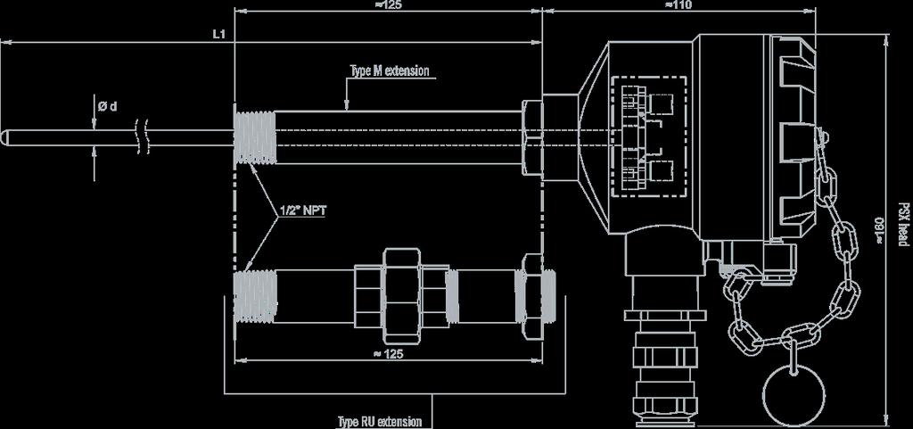
62 SENSORS FOR EXPLOSIVE ATMOSPHERES DUST ZONES 21, 22 TA2D THERMOCOUPLE IP 65 CLASS 1 IEC ANTI-EXPLOSION up to 1100 C DESCRIPTION Process sensor for use in explosible zones with a dust environment, equipped with an interchangeable measuring element. For mounting in a thermowell (see page 238). SPECIFICATIONS Model TA2D Compliance with standards IEC / EN / EN II 2 GD / Ex db IIC T6 Gb / Ex tb IIIC T85 C Db IP.6X Marking as per directive 2014/34/EU Do not open when live Do not open in the presence of dust atmospheres CE type inspection certificate LCIE 15ATEX3007 X / IECEx LCIE X Type K J T N Material Inconel L 316L Inconel 600 Pyrosil Class Diameter (d) (mm) 6-8 Hot junction Insulated / Earthed TC Single / Duplex Single Length L1 max (mm) 1,500 Max. temp. ( C) of air in sensor sheath (without airflow) (theoretical) Diam. 6 mm 1000 C 720 C 350 C 1000 C 1100 C Diam. 8 mm 1100 C 720 C 350 C 1100 C 1150 C Process connection Electrical connection Accessories Head type Material Output Cable diam. Equipment IP Type M extension - Type RU extension (makes it easy to orient the head). Threading: 1/2"NPT. Stainless steel. PSX Epoxy-coated light alloy 1 anti-explosion cable gland 3/4" NPT with nickel-plated brass fastening mm Ceramic terminal strip (standard) / Transmitter IP65 Measuring element, thermowell, cable gland 234 SENSORS CATALOGUE
63 SENSORS FOR EXPLOSIVE ATMOSPHERES DUST ZONES 21, 22 DESIGN YOUR SENSOR CONFIGURATOR CODE Parameters to be indicated when ordering MODEL HEAD TC TYPE SHEATH TYPE Ø SHEATH (mm) LENGTH L1 (mm) HOT JUNCTION EXTENSION TRANSMITTER TRANSMITTER SCALE TA2D OPTION Reference in table and diagram Possible choice PSX 1T / 1J 1K / 1N 2K / 2J 316L: AC INCONEL 600: CM PYROSIL: DB 6 / 8 Max. 1,500 mm Insulated: I (standard) Earthed: M Extension type M: M Extension type RU: R LC5334A-100: A LC5331A-321: B LC5335A-100: C THERMOCOUPLE INFORMATION 2 Class 1 TC TRANSMITTER INFORMATION (1 TC ONLY) Sheath diameter (mm) 6 8 T (CLASS 2) 316L 316L J 316L 316L K INCONEL600 INCONEL600 N INCONEL600 - PYROSIL PYROSIL 2J 316L 316L 2K INCONEL600 INCONEL600 Transmitter Input Output Galvanic insulation Reference TC 4-20mA 1.5kV LC5334A-100 TC + Pt mA 1.5kV LC5331A-321 TC + Pt mA + HART 1.5kV LC5335A ASSOCIATED CONNECTIONS ON TERMINAL STRIP Duplex thermocouple Single thermocouple + + Black - Black - Green + - For any other configuration, please contact us DIAGRAM SENSORS CATALOGUE 235
64 SENSORS FOR EXPLOSIVE ATMOSPHERES DUST ZONES 21, 22 SA2D Pt100 IP 65 CLASS A IEC ANTI-EXPLOSION up to 450 C DESCRIPTION Process sensor for use in explosible zones with a dust environment, equipped with an interchangeable measuring element. For mounting in a thermowell (see page 238). SPECIFICATIONS Model SA2D Compliance with standards IEC / EN II 2 GD / Ex db IIC T6 Gb / Ex tb IIIC T85 C Db IP.6X Marking as per directive 2014/34/EU Do not open when live Do not open in the presence of dust atmospheres CE type inspection certificate LCIE 15ATEX3007 X / IECEx LCIE X Type Pt100 Class A Mounting/Construction 1x3 wires / 1x4 wires / 2x2 wires / 2x3 wires Diameter (d) (mm) 6-8 Min./max. operating temp. ( C) C Type of measuring element DS / TS Length L1 max (mm) 1,500 Process connection Electrical connection Accessories Head type Material Output Cable diam. Equipment IP Type M extension - Type RU extension (makes it easy to orient the head). Threading: 1/2"NPT.Stainless steel. PSX Epoxy-coated light alloy 1 anti-explosion cable gland 3/4" NPT with nickel-plated brass fastening mm Ceramic terminal strip (standard) / Transmitter IP65 Measuring element, thermowell, cable gland For any other configuration, please contact us. 236 SENSORS CATALOGUE
65 SENSORS FOR EXPLOSIVE ATMOSPHERES DUST ZONES 21, 22 DESIGN YOUR SENSOR CONFIGURATOR CODE Parameters to be indicated when ordering OPTION MODEL HEAD Ø (mm) MOUNTING LENGTH L1 (mm) EXTENSION TRANSMITTER TRANSMITTER SCALE SA2D Reference in table and diagram Possible choice PSX 6 / 8 1x3 wires: B 1x4 wires: C 2x2 wires: D 2x3 wires: E Max. 1,500 mm* Extension type M: M Extension type RU: R LC5333A-100: D LC5331A-321: B LC5335A-100: C *2x2-wire mounting limited to 250mm TRANSMITTER INFORMATION (1 PT100 ONLY) Transmitter Input Output Galvanic insulation Reference Pt mA NONE LC5333A-100 TC + Pt mA 1.5kV LC5331A-321 TC + Pt mA + HART 1.5kV LC5335A CONNECTIONS 3 Connection 1 Pt100 Ω 1x4 wires Connection 2 Pt100 Ω 2x2 wires Connection 2 Pt100 Ω 2x3 wires DIAGRAM SENSORS CATALOGUE 237

66 CONCEPTEUR TEMPERATURE DE CAPTEURS SENSOR DE TEMPÉRATURE DESIGNERS MEETERING, COMPTAGE, MEASUREMENT MESURE & PERFORMANCE & ENERGY PERFORMANCE ÉNERGÉTIQUE ,6 PROXIMITY MANUMESURE possesses a network of experts ready to listen to your concerns. Twelve technical centres with ISO 9001 (quality management) and ISO14001 (environmental management) certification offer various services throughout France and internationally. > Find all the addresses on the back of this brochure. MOBILITY MANUMESURE works on all types of sites (nuclear, environmental, medical, etc.) thanks to its fleet of mobile laboratories and its teams of specially-trained technicians. MANUMESURE is the Chauvin Arnoux Group company specialized in metrology and regulatory testing. It provides metrological verification, maintenance and management of measurement, inspection and test instrument fleets in the laboratory or on customers sites. The company also proposes regulatory testing of environmental parameters (emissions of atmospheric pollutants, noise, etc.), personal safety parameters (electrical inspections, etc.) and hazard prevention parameters (thermography, etc.). Its service offering is structured around three major market segments: Industry, the Environment and Health. MANUMESURE is also a certified training organization which offers training courses adapted to our customers requirements in a wide range of technical fields. FLEET MANAGEMENT With its computerized management system with automatic reminders according to the periodicities defined, MANUMESURE manages instrument fleets for its customers. COFRAC ACCREDITATION COFRAC (Comité Français d Accréditation - French Accreditation Committee) is an internationally-recognized body which certifies the competence and impartiality of the laboratories to which it grants accreditation. > A table at the end of this brochure lists all the COFRAC accreditations. MULTI ACTIVITIES Calibration: N , N , N , N , N , N Test: N , N , N Inspection: N Reference materials: N Scope available at: REFERENCE MATERIALS YOUR CONTACTS 2018 TEST & MEASUREMENT CATALOGUE TEST & MEASUREMENT 2018 CHAUVIN ARNOUX 190, rue Championnet Paris Cedex 18 - France Tel. : Fax : info@chauvin-arnoux.fr FRANCE SOUTH-WEST SECTOR Telephone: +33 (0) sud.est@pyrocontrole.com WEST SECTOR Telephone: +33 (0) ouest@pyrocontrole.com ILE-DE-FRANCE/NORTH-EAST SECTOR Telephone: +33 (0) idf.nord.est@pyrocontrole.com INTERNATIONAL PYROCONTROLE EXPORT DEPARTMENT Telephone: +33 (0) export@pyrocontrole.com CHAUVIN ARNOUX METRIX 190, rue Championnet Paris Cedex 18 - France Tel. : Fax : info@chauvin-arnoux.fr 10 SUBSIDIARIES WORLDWIDE GERMANY CHAUVIN ARNOUX GMBH Ohmstraße KEHL / RHEIN Tel.: Fax: info@chauvin-arnoux.de ITALY AMRA SPA Via Sant Ambrogio, MACHERIO (MB) Tel. : Fax : info@amra-chauvin-arnoux.it SWITZERLAND CHAUVIN ARNOUX AG Moosacherstrasse AU / ZH Tel. : Fax : info@chauvin-arnoux.ch Catalogue général CHAUVIN ARNOUX ENERGY 16, rue Georges Besse Antony Cedex - France Tel. : Fax : info@enerdis.fr METROLOGY & REGULATORY TESTING MANUMESURE The metrology specialist MANUMESURE s advantages AUTRICHE CHAUVIN ARNOUX GES.M.B.H Slamastrasse 29/2/ WIEN Tel. : Fax : vie-office@chauvin-arnoux.at CHINA SHANGHAI PU-JIANG ENERDIS INSTRUMENTS CO. LTD N 381 Xiang De Road 3 Floor, Building SHANGHAI Tel. : Fax : info@chauvin-arnoux.com.cn SPAIN CHAUVIN ARNOUX IBÉRICA SA C/ Roger de Flor N 293 1a Planta BARCELONA Tel. : Fax : info@chauvin-arnoux.es MIDDLE EAST CHAUVIN ARNOUX MIDDLE EAST PO Box JAL EL DIB (Beirut) - LEBANON Tel. : Fax : camie@chauvin-arnoux.com UNITED KINGDOM CHAUVIN ARNOUX LTD Unit 1 Nelson Ct, Flagship Sq Shaw Cross Business Pk, Dewsbury West Yorkshire - WF12 7TH Tel. : Fax : info@chauvin-arnoux.co.uk SCANDINAVIA CA MÄTSYSTEM AB Sjöflygvägen 35 SE TABY Tel. : Fax : info@camatsystem.com USA CHAUVIN ARNOUX INC d.b.a AEMC Instruments 15 Faraday Drive Dover - NH Tel. : +1 (800) Fax : +1 (603) sales@aemc.com MANUMESURE 9, allée Jean Prouvé Clichy - France Tel. : Fax : info@manumesure.fr FRANCE PYROCONTROLE 6 bis, av du Docteur Schweitzer Meyzieu Cedex - France Tel. : Fax : info@pyrocontrole.com MIDDLE EAST Chauvin Arnoux Middle East P.O. BOX JAL EL DIB - LEBANON Tel: Fax: camie@chauvin-arnoux.com UNITED KINGDOM Chauvin Arnoux Ltd Unit 1 Nelson Ct, Flagship Sq, Shaw Cross Business Pk Dewsbury, West Yorkshire - WF12 7TH Tel: Fax: info@chauvin-arnoux.co.uk
Hazardous Areas - EXPLOSIONPROOF SOLENOIDS
 Hazardous Areas - EXPLOSIONPROOF SOLENOIDS SOME HISTORY The classification of hazardous areas into zones established the level of protection required for electrical equipment installed in explosive gas
Guide for hazardous areas
 Guide for hazardous areas 1 Hazardous areas definitions 2 Gas and dust s 3 Temperature classifications 4 Common flammable gases, vapours and dust types 5 Protection concepts ATEX and IECEx 6 Protection
REGULATIONS EUROPEAN ATEX DIRECTIVE. INTERNATIONAL SCHEME: IECEx AREAS CLASSIFICATION DEFINED BY DIRECTIVE 1999/92/EC
 EUROPEAN ATEX DIRECTIVE > European Directive 2014/34/EU ATEX Directive 2014/34/EU is a "new approach" directive that applies to protective systems against explosions as well as all equipment used in or
The R. STAHL Technology Group Worldwide Success with Competence and Customer Support
 The R. STAHL Technology Group Worldwide Success with Competence and Customer Support The entrepreneurial basis of the R. STAHL Technology Group follows a long tradition. The product range is aimed at specialised
Weighing Solutions for Hazardous Areas FULL COMPLIANCE WITH ATEX DIRECTIVE
 Weighing Solutions for Hazardous Areas FULL COMPLIANCE WITH ATEX DIRECTIVE PUE HX5.EX explosion-proof hazardous area indicator ATEX APPROVAL PUE HX5.EX is a cutting-edge weighing indicator, designed to
ATEX, NOMENCLATURE AND CODING
 Technical Notes ATEX, NOMENCLATURE AND CODING The intent of this technical note is approach to the user to the ATEX normative. For this we will begin defining, what is an explosive atmosphere, what are
ATEX, NOMENCLATURE AND CODING
 ATEX, NOMENCLATURE AND CODING The intent of this technical note is approach to the user to the ATEX normative. For this we will begin defining, what is an explosive atmosphere, what are ATEX, as well as
Airo Wireless Intrinsically Safe White Paper. Written By: David Schmitt
 Airo Wireless Intrinsically Safe White Paper Written By: David Schmitt Intrinsically Safe Cell Phone/Smartphone/PDA Intrinsically Safe (IS) is a protection certification for safe operation with electronic
ATEX - GUIDE. A short introduction to ATEX Terminology. Equipment for use in flammable atmospheres C E R T I F I E D DANISH TECHNOLOGICAL INSTITUTE
 DANISH TECHNOLOGICAL INSTITUTE The Danish Technological Institute is a self-owned and not-f-profit institution. We develop, apply and disseminate research- and technologically-based knowledge f the Danish
1. GENERAL TECHNICAL INFORMATION
 1. GENERAL TECHNICAL INFORMATION 1.1 EXPLOSIVE ATMOSPHERES: Every time that dangerous quantities and concentration of flammable gas, vapors mixture or dust clouds exists, risk of explosions may arise.
A GUIDE TO EUROPEAN (EEC) CERTIFICATION FOR ELECTRICAL EQUIPMENT IN HAZARDOUS AREAS
 CERTIFICATION FOR ELECTRICAL EQUIPMENT IN HAZARDOUS AREAS") A GUIDE TO EUROPEAN (EEC) CERTIFICATION FOR ELECTRICAL EQUIPMENT IN HAZARDOUS AREAS For a print friendly page click here INTRODUCTION Hazardous areas are those in which there exists a risk of explosion
A GUIDE TO EUROPEAN (EEC) CERTIFICATION FOR ELECTRICAL EQUIPMENT IN HAZARDOUS AREAS For a print friendly page click here INTRODUCTION Hazardous areas are those in which there exists a risk of explosion
Overview of Hazardous Locations as They Relate to Solenoid Valves
 Overview of Hazardous Locations as They Relate to Solenoid Valves Defined: Hazardous Location - "where fire or explosion hazards may exist due to flammable gases or vapors, flammable liquids, combustible
PYROS. Código: FT-PY01-I Revisión: TECHNICAL DATA. Polycarbonate tube of 4 mm. thickness LIGHT FITTING. Laquered steel painted white
 . TECHNICAL DATA LIGHT FITTING REFLECTOR Polycarbonate tube of 4 mm. thickness Laquered steel painted white END CAPS Aluminium 2030 (polyester paint RAL 7047) POWER SOURCE LAMP TYPE 220-240V, 50/60Hz T8
Explosion-protected actuator Page 259 of 292
 Explosion-protected actuator Page 259 of 292 9.5 Explosion-protected actuator 9.5.1. What is an explosion? A flammable substance and oxygen, in a certain mixture, must be available to set off an explosion.
Beamex. Calibration White Paper. Calibration in hazardous areas
 Beamex Calibration White Paper info@beamex.com Calibration in hazardous areas This article discusses calibration in hazardous areas and what everyone needs to be aware of before entering into a hazardous
ATEX - GUIDE. A short introduction to ATEX Terminology. Equipment for use in flammable atmospheres
 Quick Introduction to: DANISH TECHNOLOGICAL INSTITUTE The Danish Technological Institute is a self-owned and not-fprofit institution. We develop, apply and disseminate research- and technologically-based
UL HAZARDOUS LOCATIONS SERVICES
 UL HAZARDOUS LOCATIONS SERVICES The international preference in hazardous locations certification for over 100 years ul.com/hazloc Explosive Gas Atmospheres Class I Division S Includes flammable gases,
EUROPEAN DIRECTIVES Explosive atmospheres ATEX 2014/34/EU
 EUROPEAN DIRECTIVES Explosive atmospheres ATEX 2014/34/EU GENERAL The accidental ignition of an atmosphere containing a large quantity of gas, vapour, mists and/or dust may cause an explosion. Specific
Beamex Calibration White Paper. Calibration in hazardous areas
 Beamex Calibration White Paper info@beamex.com Calibration in hazardous areas This article discusses calibration in hazardous areas and what everyone needs to be aware of before entering into a hazardous
ATEX Safety Switches. More than safety.
 ATEX Safety Switches More than safety. AUDIN - 8, avenue de la malle - 5370 Saint Brice Courcelles Tel : 03.6.0.0. - Fax : 03.6.0.8.0 - Web : http: www.audin.fr - Email : info@audin.fr ATEX products from
Implementation of ATEX Guidelines
 Implementation of ATEX Guidelines Temperature and Climatic Test Chambers for Usage under Conditions Carrying a Risk of Fire and Explosion What are ATEX guidelines? Introduction Duties of the system user...
VSD AND SS DRIVING ATEX MOTORS February 2014
 VSD AND SS DRIVING ATEX MOTORS February 2014 1 Introduction to ATEX 2 ATEX motor designation 3 VSD Sample Solutions 4 SS descriptions Introduction to ATEX EU territory define the use of electrical equipment
Selection of Explosion Protected Equipment for Hazardous Locations. Compiled by: Pieter Coetzee ZONE 2 ZONE 1 ZONE 0.
 Selection of Explosion Protected Equipment for Hazardous Locations Compiled by: Pieter Coetzee ZONE 2 ZONE 0 ZONE 1 Be safe be Ex Contents Introduction Occupational Health and Safety Act. (Act 85 of 1993)
Multipoint temperature sensor
 Multipoint temperature sensor ATEX e / t for use in areas with an explosion hazard Persons concerned: Experienced professional electricians as per EU Directive 1999/92/EC and trained personnel B 903530.0.0
S T R I T T & P R I E B E I N C.
 Equipment Enclosure Comparisons Type of Enclosure European - Area of use Designation Standard IEC - Area of use Designation Standard USA - Area of use Designation Standard Flameproof Enclosure An enclosure
Switches compliant with ATEX directive
 Switches compliant with ATEX directive General Catalogue - Technical concepts page Position switches FD / FL series page 9 / Category Zone EPL Approvals 2G Gb Mb II 2G Ex ia IIC T6 Gb I Ex ia I Mb Product
EJBX. Ex d. AISI 316L stainless steel. - Zone 1, 2, 21, 22 - Group IIB+H2 - Stainless steel junction boxes - Choice of 13 sizes - IP 66 / 67
 Ex d EJBX AISI 316L stainless steel - Zone 1, 2, 21, 22 - Group IIB+H2 - Stainless steel junction boxes - Choice of 13 sizes - IP 66 / 67 Quartz sand blasting Warning labels Mounting bracket Silicone gasket
RE: USE OF FIREPRO IN POTENTIALLY EXPLOSIVE ATMOSPHERES
 Limassol 20 th August, 2015 RE: USE OF FIREPRO IN POTENTIALLY EXPLOSIVE ATMOSPHERES This document is intended to provide clarification on the use of FirePro Condensed Aerosol Generators in Potential Explosive
OPTIBAR DP 7060 Supplementary Instructions
 OPTIBAR DP 7060 Supplementary Instructions Differential pressure transmitter Category ATEX II 1/2G, 2G Ex db ia IIC T6...T1 Ga/Gb, Gb IECEx Ex db ia IIC T6...T1 Ga/Gb, Gb Housing Aluminium: Single chamber,
ATM Lighting sp. z o.o
 INSTALLATION AND MAINTENANCE MANUAL FOR EXPLOSIONPROOF LIGHT FITTING EXL210LED Carefully read the instructions before mounting the light fitting. ATM Lighting sp. z o.o., ul. Budowlanych 31, 80-298 Gdańsk,
ATEX GUIDE. A short introduction to ATEX Terminology. Equipment for use in flammable atmospheres. Directive 94/9/EC
 Quick Introduction to TÛV Denmark TÜV Denmark - is a part of the TÜV NORD Group a global Organisation f Certification and Inspection of: Quality Management Systems, Products, Processes and Qualification
ATEX - ATmosphere EXplosive
 ATEX - ATmosphere EXplosive 153 DIRECTIVE 94/9/CE (ATEX= ATMOSPHERE EXPLOSIVE) OF THE EUROPEAN PARLIAMENT AND COUNCIL (MARCH 23, 1994): IMPACT ON LIGHTING FIXTURES APPLICATIONS Polycarbonate and steel
Dräger Polytron 5700 IR Detection of flammable gases and vapours
 Dräger Polytron 5700 IR Detection of flammable gases and vapours The Dräger Polytron 5700 IR is a cost effective explosion-proof transmitter for the detection of flammable gases in the lower explosive
Additional Operating Instructions SITRANS F. Vortex flowmeters. SITRANS FX330 Ex-d.
 Additional Operating Instructions SITRANS F Vortex flowmeters Ex-d Edition 09/208 CONTENTS Safety instructions 3. General notes... 3.2 EU conformity... 3.3 Approval according to the IECEx scheme... 3.4
INSTRUCTION MANUAL (ATEX / IECEx)
") INSTRUCTION MANUAL (ATEX / IECEx) BExS110D and BExS110D-R Sounder For use in Flammable Gas and Dust Atmospheres BExS110D BExS110D-R 1) Warnings DO NOT OPEN WHEN AN EXPLOSIVE ATMOSPHERE IS PRESENT DO NOT
INSTRUCTION MANUAL (ATEX / IECEx) BExS110D and BExS110D-R Sounder For use in Flammable Gas and Dust Atmospheres BExS110D BExS110D-R 1) Warnings DO NOT OPEN WHEN AN EXPLOSIVE ATMOSPHERE IS PRESENT DO NOT
[ TECHNOLOGY ] and does this definition affect a burner.
![[ TECHNOLOGY ] and does this definition affect a burner.](/thumbs/72/67499288.jpg "[ TECHNOLOGY ] and does this definition affect a burner.") [ TECHNOLOGY ] JBD-11,500-G type burner for natural gas ATEX, EExd Zone 2. For combined cycle power plant in Riga Latvia. Aitor Fernández Project Engineer Automation Department Head afernandez@emcombustion.es
[ TECHNOLOGY ] JBD-11,500-G type burner for natural gas ATEX, EExd Zone 2. For combined cycle power plant in Riga Latvia. Aitor Fernández Project Engineer Automation Department Head afernandez@emcombustion.es
Erik Leider Project Engineer Hazardous Locations, Gas & Oil Underwriters Laboratories
 Hazardous Locations: Understanding the Basics of Global Compliance Requirements Erik Leider Project Engineer Hazardous Locations, Gas & Oil Underwriters Laboratories DISCLAIMER/ TERMS OF USE: THE INFORMATION
MICROpeL 75 Combustible Gas Sensor Part Number: PM
 MICROpeL 75 Combustible Gas Sensor Part Number: PM759-000 Key Features & Benefits: ATEX, UL and CSA Approvals Withstands EN/IEC 60079-0 impact test Enhanced H 2 S and silicone poison resistance Reduced
Hazardous area descriptions
 Hazardous area descriptions National Electrical Code (NEC) 500 Traditional standards used in North America. Example: Class I, Div 1, Group B, C, D, T4 Permitted Class Permitted Division Permitted Group
ATM Lighting sp. z o.o
 INSTALLATION AND MAINTENANCE MANUAL FOR EXPLOSIONPROOF LIGHT FITTING EXL390LED Carefully read the instructions before mounting the light fitting. ATM Lighting sp. z o.o., ul. Budowlanych 31, 80-298 Gdańsk,
THE BELGIAN PIONEER IN GAS DETECTION
 DAT 420 Gas or oxygen detector INSTRUCTION MANUAL THE BELGIAN PIONEER IN GAS DETECTION Copyright 2016 by DALEMANS s.a. Revision V1R7 07/2016 Any reproduction, whether partial or entire, made of this document,
Technical Data. Dimensions
 0102 Model Number Features 5 mm flush Usable up to SIL2 acc. to IEC 61508 Accessories EXG-18 Quick mounting bracket with dead stop BF 18 Mounting flange, 18 mm Technical Data specifications Switching element
Intrinsically Safe Pressure Transmitters for installation in hazardous locations Models IS-20-S, IS-21-S, IS-20-F, IS-21-F WIKA Datasheet IS-20
 Electronic Pressure Measurement Intrinsically Safe Pressure Transmitters for installation in hazardous locations Models IS-20-S, IS-21-S, IS-20-F, IS-21-F WIKA Datasheet IS-20 Applications Chemical, Petrochemical
OPTIWAVE X500 Supplementary Instructions
 OPTIWAVE X500 Supplementary Instructions OPTIWAVE 3500 C OPTIWAVE 6500 C OPTIWAVE 7500 C Supplementary Instructions for ATEX applications KROHNE CONTENTS OPTIWAVE X500 1 General safety information 4 1.1
A guide to the use of electrical equipment in potentially explosive atmospheres To view this document in PDF format click here.
 A guide to the use of electrical equipment in potentially explosive atmospheres To view this document in PDF format click here Introduction Potentially Explosive Atmospheres exist where there is a risk
Guide to Hazardous Location Approvals:
 Selection Guide Guide to Hazardous Location Approvals: MICRO SWITCH Hazardous Area Limit Switches Introduction There are many considerations when selecting a switch to be used in hazardous areas. In addition
Guide to Hazardous Location Approvals: MICRO SWITCH Hazardous Area Limit Switches
 Guide to Hazardous Location Approvals: MICRO SWITCH Hazardous Area Limit Switches A Selection Guide Introduction There are many considerations when selecting a switch to be used in hazardous areas. In
Dual certification! Air handling units for potentially explosive atmospheres
 Dual certification! Air handling units for potentially explosive atmospheres X-CUBE Ex A certified safety product The air handling unit with dual ATEX certification ATEX directive 2014/34/EU applies to
Technical Data. General specifications. Rated operating distance s n 5 mm
 0102 Model Number Features 5 mm non-flush Usable up to SIL 2 acc. to IEC 61508 Technical Data specifications Switching function Normally closed (NC) Output type NAMUR Rated operating distance s n 5 mm
Introduction to Hazardous Electrical Location Classifications
 Introduction to Hazardous Electrical Location Classifications Introduction In North America the target audience for this white paper and the electrical code classification ratings for various types of
INSTRUCTION & SERVICE MANUAL
 INSTRUCTION & SERVICE MANUAL D2xC1 ALARM HORN AND STROBE For Use In Hazardous Locations 3) Ratings and Markings 3.1 ATEX / IECEx certification The D2xC1 Alarm Horn and Strobe complies with the following
Immersion heaters for ATEX/IECEx hazardous areas or in non-atex version
 for ATEX/IECEx hazardous areas or in non-atex version * Non contractual picture Warning It is imperative to read these instructions carefully before installing or maintaining the equipment. MI100EN 09/2017
Explosion-proof Immersion Heater Type D-8660
 Explosion-proof Immersion Heater Type D-8660 Sinus Jevi has developed explosionproof Ex de heating equipment, for hazardous area. The flame-proof (d) enclosures have been designed for non save areas to
Officine Meccaniche M.A.M. series for command, control, signaling and/or automation. DOCUMENT IS-EJB-A-14 rev. 0
 Officine Meccaniche M.A.M. Apparecchiature Antideflagranti DOCUMENT IS-EJB-A-14 rev. 0 Instructions Flameproof enclosures EJB../W series for command, control, signaling and/or automation Emission date:
Intrinsically Safe Solutions
 Intrinsically Safe Solutions INSTALLATION MANUAL 04/12/14 Rev D DOC-01-029 Documentation Feedback Your feedback helps us keep our documentation up to date and accurate. If you have any comments or suggestions
Technical Data. General specifications Switching element function Rated operating distance s n 5 mm
 0102 Model Number Features 5 mm non-flush Usable up to SIL2 acc. to IEC 61508 Technical Data specifications Switching element function NAMUR, NC Rated operating distance s n 5 mm Installation non-flush
Equipment and Solutions
 Equipment and Solutions Solution [formally technor atex] Subject to errors or changes Editing completed January 2016 Ex-tech Group is located at Forus in Stavanger, Norway, one of the world s top Centers
Drive Technology \ Drive Automation \ System Integration \ Services * _0817* Inquiry Forms for Explosion-Proof Gearmotors
 Drive Technology \ Drive Automation \ System Integration \ Services *23511257_0817* Inquiry Forms for Explosion-Proof Gearmotors Edition 08/2017 23511257/EN SEW-EURODRIVE Driving the world Inquiry forms
Inductive slot sensor
 0102 Model Number Features 2 mm slot width Technical Data specifications Switching function Normally closed (NC) Output type NAMUR Slot width 2 mm Depth of immersion (lateral) 5... 7 mm, typ. 6 mm Output
Selecting a Safe Tank Gauging Product. Understanding Hazardous Area Definitions for Equipment Approvals
 Selecting a Safe Tank Gauging Product Understanding Hazardous Area Definitions for Equipment Approvals Hazardous Area Approvals A Worldwide Requirement There are many environmental considerations within
Flammable gases Detectors. Model DAX 03F DAX 03F- C DAX 03F- H. Note for installation, use and maintenance. Version 1.2
 Flammable gases Detectors Model DAX 03F DAX 03F- C DAX 03F- H Note for installation, use and maintenance Version 1.2 Introduction This handbook must be read carefully by any person who has or will have
Additional Operating Instructions SITRANS F. Vortex flowmeters. SITRANS FX330 Ex-i.
 Additional Operating Instructions SITRANS F Vortex flowmeters Ex-i Edition 09/2018 CONTENTS 1 Safety instructions 3 1.1 General notes... 3 1.2 EU conformity... 3 1.3 Approval according to the IECEx scheme...
INSTRUCTION MANUAL (ATEX/IECEx/SIL2) BExBG05D-SIL Flameproof Xenon SIL 2 Beacons For use in Flammable Gas and Dust Atmospheres
 BExBG05D-SIL Flameproof Xenon SIL 2 Beacons For use in Flammable Gas and Dust Atmospheres") INSTRUCTION MANUAL (ATEX/IECEx/SIL2) BExBG05D-SIL Flameproof Xenon SIL 2 Beacons For use in Flammable Gas and Dust Atmospheres 1) Introduction The BExBG05D-SIL is a flameproof beacon which is certified
INSTRUCTION MANUAL (ATEX/IECEx/SIL2) BExBG05D-SIL Flameproof Xenon SIL 2 Beacons For use in Flammable Gas and Dust Atmospheres 1) Introduction The BExBG05D-SIL is a flameproof beacon which is certified
4P75 CiTipeL Combustible Gas Sensor Part Number: PM
 Product Datasheet 4P75 Document Purpose The purpose of this document is to present the performance specification of the 4P75 CiTipeL. This document should be used in conjunction with Operating Principles
Dräger Polytron 8310 IR Detection of flammable gases and vapour
 Dräger Polytron 8310 IR Detection of flammable gases and vapour The Dräger Polytron 8310 IR is an advanced explosion proof transmitter for the detection of combustible gases in the lower explosion limit
AD.3.XG... Atex directive ch. I Page 22 Atex classification ch. I Page 23. Tab.1 Assembly ch. I Page 25
 Atex directive ch. I Page 22 Atex classification ch. I Page 23 Series ch. I Page 24 Technical specifications Ch. I Page 24 Ordering code ch. I Page 24 Tab. Assembly ch. I Page 25 Tab. 2 Voltages ch. I
Additional Operating Instructions SITRANS F. Vortex flowmeters. SITRANS FX330 Ex-nA.
 Additional Operating Instructions SITRANS F Vortex flowmeters Ex-nA Edition 08/207 CONTENTS Safety instructions 3. General notes... 3.2 EU conformity... 3.3 Approval according to the IECEx scheme... 3.4
INSTRUCTION MANUAL. E2xB05 & E2xB10 Xenon Beacons For use in Hazardous Locations
 INSTRUCTION MANUAL E2xB05 & E2xB10 Xenon Beacons For use in Hazardous Locations 1) Warnings DO NOT OPEN WHEN AN EXPLOSIVE ATMOSPHERE IS PRESENT DO NOT OPEN WHEN ENERGISED POTENTIAL ELECTROSTATIC CHARGING
Technical Data. Dimensions
 0102 Model Number Features 8 mm non-flush Stainless steel housing Usable up to SIL2 acc. to IEC 61508 Technical Data specifications Switching element function NAMUR, NC Rated operating distance s n 8 mm
Guide to Intrinsically Safe Portable Radios
 Guide to Intrinsically Safe Portable Radios An overview of common IS standards www.taitradio.com GUIDE TO INTRINSICALLY SAFE PORTABLE RADIOS SUMMARY The development of equipment for explosive atmospheres
PrimaX IR Gas Transmitter Designed for Reliable Performance in Extreme Conditions
 PrimaX IR Gas Transmitter Designed for Reliable Performance in Extreme Conditions Because every life has a purpose PrimaX IR Gas Transmitter Every feature of the SIL 2 engineered PrimaX IR Gas Transmitter
INSTRUCTION MANUAL IS-mB1 Minialite Intrinsically Safe Round LED Beacon
 INSTRUCTION MANUAL Minialite Intrinsically Safe Round LED This instruction sheet describes installations which conform to EN60079:Part14:2008 Electrical Installation in Hazardous Areas. When designing
HAZARDOUS AREA CLASSIFICATION AND SELECTION OF EQUIPMENT FOR SAFE USE THEREIN FROM AN ELECTRICAL VIEWPOINT
 HAZARDOUS AREA CLASSIFICATION AND SELECTION OF EQUIPMENT FOR SAFE USE THEREIN FROM AN ELECTRICAL VIEWPOINT Olof Bekker Pr. Eng. BSc. Eng. BML S.MSAIEE, M.NACE Engineering Manager, Electrical COMMITMENT
Electrical Installations Design, Selection, Erection and Inspection
 IECEx International Conference 2018 Jakarta, Indonesia Electrical Installations Design, Selection, Erection and Inspection IECEx International Conference 2018 Jakarta, Indonesia Peter Thurnherr thuba Ltd.,
Dräger Polytron 8700 IR Detection of flammable gases and vapors
 Dräger Polytron 8700 IR Detection of flammable gases and vapors The Dräger Polytron 8700 IR is an advanced explosion proof transmitter for the detection of combustible gases in the lower explosion limit
HOW TO FIND THE RIGHT DEVICE FOR YOUR FACILITY
 HOW TO FIND THE RIGHT DEVICE FOR YOUR FACILITY Cell Phones Smartphones PDA integrating people, products and processes Intrinsically Safe Cell Phone/Smartphone/PDA Intrinsically Safe (IS) is a protection
Smart encoders & actuators
 Declaration of Conformity The manufacturer: LIKA ELECTRONIC SRL 36010 Carrè (VI) - Italy hereby declares that the following products (only when correctly assembled): XAC8018/1PB-14 XAC8018/1CB-14 XAC8018/1FD-14
Centurion Guided Radar HAWK CGR SERIES
 Safety Instructions CGR (Cat 3GD) Centurion Guided Radar HAWK CGR SERIES ATEX Category 3GD Intrinsically Safe probe / Flameproof enclosure II 3G Ex ia/d IIC T6 T2 Gc II 3D Ex ia tb IIIC T85 C T255 C Dc
Pressure sensors. Ex ia I / IIC T6 acc. to ATEX. Features. Description. Measuring ranges. Applications
 Force Pressure Temperature Switch Pressure sensors Ex ia I / IIC T6 acc. to ATEX with internal diaphragm with front flush diaphragm Accuracy: 0,25% and 0,5 % Standard output: 4...20 ma; 2-wire system Description
Dräger Polytron 8700 IR Detection of flammable gases and vapors
 Dräger Polytron 8700 IR Detection of flammable gases and vapors The Dräger Polytron 8700 IR is an advanced explosion proof transmitter for the detection of combustible gases in the lower explosion limit
Guidelines for Market Surveillance of Equipment for Explosive Environments (Hazardous Locations)
") Annex II Guidelines for Market Surveillance of Equipment for Explosive Environments (Hazardous Locations) 1. According to Recommendation L, market surveillance should be included as a flanking area of
Annex II Guidelines for Market Surveillance of Equipment for Explosive Environments (Hazardous Locations) 1. According to Recommendation L, market surveillance should be included as a flanking area of
Temperature Measurement Transmitters for field mounting
 Siemens AG 07 Overview Application The SITRANS TF can be used everywhere where temperatures need to be measured under particularly harsh conditions. For that reasons users from all industries have opted
Certificate of Compliance
 FF0 001 Certificate of Compliance Certificate: 70116284 (LR 064969_0_00) Issued to: Mine Safety Appliances Company North American Division 1000 Cranberry Woods Dr Cranberry Township, Pennsylvania 16066-5296
WHAT WHITE PAPER IS POTENTIALLY EXPLOSIVE ATMOSPHERE CERTIFICATION AND WHY YOU. June 2010
 WHITE PAPER WHAT IS POTENTIALLY EXPLOSIVE ATMOSPHERE CERTIFICATION AND WHY YOU MAY NEED IT! June 2010 Copyright Extronics Ltd 2010 The information contained in this document is subject to change without
Dräger Flame 2500 (IR3) Flame Detection
 Flame Detection") Dräger Flame 2500 (IR3) Flame Detection With its triple IR sensor The Dräger Flame 2500 detects hydrocarbonbased fires even over greater distances. Moreover, it offers a high reliability against false
Dräger Flame 2500 (IR3) Flame Detection With its triple IR sensor The Dräger Flame 2500 detects hydrocarbonbased fires even over greater distances. Moreover, it offers a high reliability against false
Duct heaters for ATEX/IECEx hazardous areas or in non-atex version
 for ATEX/IECEx hazardous areas or in non-atex version * Non contractual picture Warning It is imperative to read these instructions carefully before installing or maintaining the equipment. MI200EN 09/2017
Certificate of Compliance
 FF0 001 Certificate of Compliance Certificate: 70116279 (LR 025993_0_000) Issued to: General Monitors, Incorporated 26776 Simpatica Circle Lake Forest, California 92630 USA Attention: Larry Vlagea The
Technical Data. General specifications Switching element function Rated operating distance s n 8 mm
 0102 Model Number Features 8 mm non-flush Usable up to SIL 3 acc. to IEC 61508 Application Danger! In safety-related applications the sensor must be operated with a qualified fail safe interface from Pepperl+Fuchs,
Competence for Safety. ATEX Category 3 Description. Example of a zone division for combustible fluids (gases) and combustible dust
 and combustible dust") Competence for Safety Within the scope of the creation of the explosion protection document (mandatory for the operator according to ATEX 137), production locations must be divided into zones depending
Competence for Safety Within the scope of the creation of the explosion protection document (mandatory for the operator according to ATEX 137), production locations must be divided into zones depending
Circulation heaters for ATEX/IECEx hazardous areas or in non-atex version
 for ATEX/IECEx hazardous areas or in non-atex version * Non contractual picture Warning It is imperative to read these instructions carefully before installing or maintaining the equipment. MI500EN 09/2017
manual addendum DELPHI Ex
 manual addendum DELPHI Ex II 2G Ex eb IIC T4 Gb II 2D Ex tb IIIC T135 C IP65 Db Tamb=-20 +40 C Reference list: Norm (last issue) Title Dir. 2014/34/UE EN 60079-31 EN60079-0 EN60079-7 Equipment and Protective
VERSAFLOW VORTEX Supplementary instructions
 VERSAFLOW VORTEX Supplementary instructions Vortex flowmeter Equipment category II 2G CONTENTS VERSAFLOW VORTEX 1 Safety instructions 3 1.1 General notes... 3 1.2 EC conformity... 3 1.3 Approval according
PESO. Temperature sensors with cables Thermocouples and RTD temperature probes ATEX I, e, t For use in areas with an explosion hazard
 Temperature sensors with cables Thermocouples and RTD temperature probes ATEX I, e, t For use in areas with an explosion hazard Persons concerned: Experienced professional electricians as per EU Directive
ESSENTIAL EXPLOSION PROTECTION
 ESSENTIAL EXPLOSION PROTECTION 2 3 FOREWORD In many industries, gases, vapours, mist and dust develop and escape in the course of manufacturing, processing, transporting and storing combustible substances.
Detection of explosive gases, toxic gases or oxygen. Infrared XP version. SIL 2 high reliability IP 66. Aluminium or Stainless Steel version
 Fixed Gas Detector Detection of explosive gases, toxic gases or oxygen Infrared XP version SIL 2 high reliability IP 66 Aluminium or Stainless Steel version Certifications Pending The Fixed Gas Detection
Technical Data. General specifications Switching element function Rated operating distance s n 5 mm
 0102 Model Number Features 5 mm flush Usable up to SIL 3 acc. to IEC 61508 Application Danger! In safety-related applications the sensor must be operated with a qualified fail safe interface from Pepperl+Fuchs,
Industrial Cast-in Circulation Heaters for ATEX/IECEx hazardous areas or in non-atex version
 heating for a better future Industrial Cast-in Circulation Heaters for ATEX/IECEx hazardous areas or in non-atex version HEATING GASES HEATING LIQUIDS The CETAL-developed Cast-In Circulation Heater Technology
OLC(T) 100 FIXED GAS DETECTOR
 100 FIXED GAS DETECTOR") Fixed Gas Detector OLC(T) FIXED GAS DETECTOR Detection of explosive gases, toxic gases or oxygen Infrared XP version SIL 2 high reliability IP 66 Aluminium or Stainless Steel version CERTIFICATIONS The
Fixed Gas Detector OLC(T) FIXED GAS DETECTOR Detection of explosive gases, toxic gases or oxygen Infrared XP version SIL 2 high reliability IP 66 Aluminium or Stainless Steel version CERTIFICATIONS The
Technical Data. General specifications Switching element function Rated operating distance s n 4 mm
 0102 Model Number Features 4 mm non-flush Accessories BF 12 Mounting flange, 12 mm Technical Data specifications Switching element function NAMUR, NO Rated operating distance s n 4 mm Installation non-flush
Drive systems for the chemical, oil and gas industry. Electric drives and systems
 Drive systems for the chemical, oil and gas industry Electric drives and systems 2 VEM drive systems for the chemical, oil and gas industry VEM drive systems for the chemical, oil and gas industry 3 VEM