HIGH VOLTAGE A.C.(50 or 60Hz) CONTACT CAPACITIVE HIGH VOLTAGE DETECTOR
|
|
|
- Irene Hodges
- 5 years ago
- Views:
Transcription
 CONTACT CAPACITIVE HIGH VOLTAGE DETECTOR INSTRUCTION MANUAL 99 Washington Street Melrose, MA")
1 HIGH VOLTAGE A.C.(50 or 60Hz) CONTACT CAPACITIVE HIGH VOLTAGE DETECTOR INSTRUCTION MANUAL 99 Washington Street Melrose, MA Phone Toll Free Visit us at
2 Index 1. Safety rules General description Principle of how it work A quick review of it's inside working Labeling Front panel layout - facia Main label warning Preparation for use Care and maintenance Periodic maintenance Checking and proofing the tester Typical uses Instructions for use Assembling the equipment Using the equipment Interference voltages Specifications Models and comparison table Questions / answers Limited warranty... Page
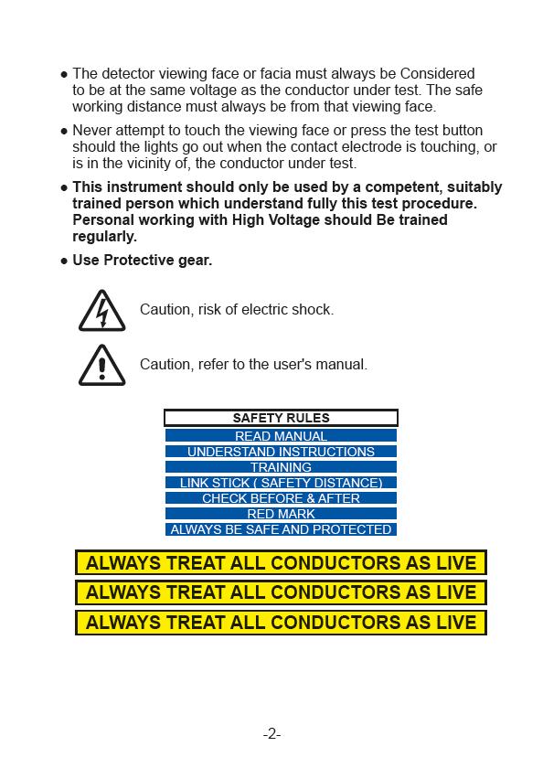
3 1. Safety notes These Contact High Voltage Detectors have been designed with safety in mind. However, no design can completely protect against incorrect use. Electrical circuits are dangerous and lethal through lack of caution or poor safety practice. Follows Safety rules to reduce danger and practice safety. Read the User's manual carefully and completely before using the tester. Fully understand the instructions before using this product. Follow the instructions for every test. Take all the necessary precautions. Do not exceed the limits of this instrument. Only personnel who are fully trained in the use of High Voltage Detectors should use this equipment. The systems that it will be used on are powered from High Voltages which are lethal. Always use a fiber glass rod or an authorised insulated Stick of the correct specifications and minimum safe operating distance. A High voltage test is carried out with the tester attached to an operating stick, sometime called "links stick" (or Hot Stick...etc...). Before use, ensure that the detector and it's accessories that are required for use are clean, free from cracks or deep scores, and are properly secured together. Always check that the detector is working Correctly before and after the test. Make certain that the detector is properly rated for the Voltage of the system under test. Do not touch any exposed wiring, connections or other "Live" parts of an electrical circuit. Check the operation of the assembled detector complete with accessories before and after each test. Do not allow a live high voltage conductor to come in contact with the detector at a point below the limit mark. The detector must never be used without a handle or without insulating rods incorporating a handle. Safe working distances must always be observed. -1-
4
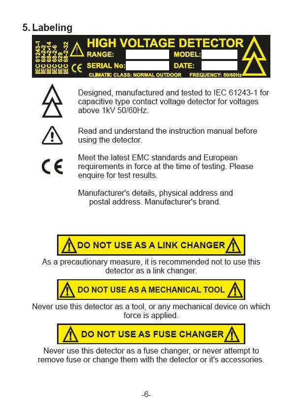
5 2. General description The range of capacitive high voltage detectors has been designed to meet the requirements of the latest International IEC standards (IEC ). They may be used indoors and outdoors in all weathers. The detectors are intended for use on high voltage systems but not in switchgear. Models are available to cover a wide range of system voltages. The function of the detector is to determine whether a conductor is energised or de-energised so that it may be safely earthed before commencing work. Protection class : IP Principles of how it work A strong cone shaped nylon moulding houses the detector. The inner wall of the cone has a conductive screen coating to which the earthy parts of the circuit are connected. This screen coating is capacitively coupled to the earth of the electric field and acts as a voltage divider with an internal sensing capacitor (The internal sensing capacitor is different from voltage range to voltage range). High voltage appearing at the electrode is divided down and the voltage across the sensing capacitor is proportional to the voltage between the electrode and earth. This proportional signal voltage is fed to the electronic circuitry whose output drives an audible warning device and a system of indicating lamps. The electronic circuitry has some scaling circuitry, an amplifier, rectifier and a comparator circuit. The threshold of the comparator is set at the factory or set by an authorised calibration facility. This range of capacitively coupled high Voltage Detectors uses multilayer boards with ground planes all over the board, eliminating false or noisy signals. -3-
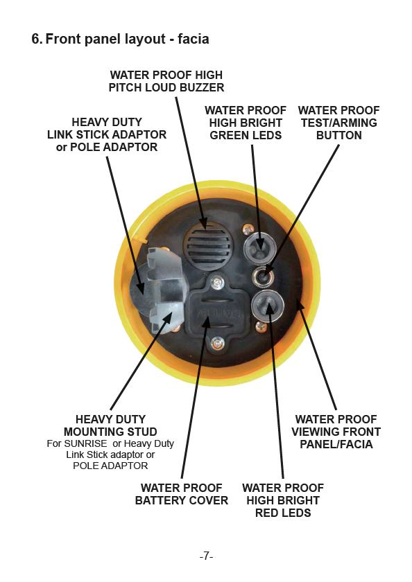
6 4. A quick overview of it's inside working Arming The detector has a combined manual and a self arming mode. Manual Arming Mode The ARMING/TEST button is mounted on the front viewing face of the detector (the front viewing face of the detector has the buzzer, mounting stud (which has the attachment adaptor to the link stick), arming/test button and the lights It's also called the Facia). When this button is depressed, the High Bright Red Leds flashes twice per second and the loud Buzzer (audible warning device) sounds also twice per second. This is the display for voltage PRESENT. Pressing the button, activate an internal oscillator, and couple it to the input of the sensing circuitry, tough, simulating an external voltage. When the button is released the display changes to the High Bright Green flashing LEDs (also twice per second). This is the display for voltage NOT PRESENT and battery OK. The detector is then armed and ready for use. This armed condition lasts for about 3 minutes. Arming the detector also functionally checks the internal circuitry but does not check the input protections or contact electrode extension nor the internal sensing capacitor for an open circuit condition. Use an external proofing unit for this. Self Arming Mode In this mode of operation the detector automatically switches, ON when a High Voltage A.C. is applied to the contact electrode. Indicating lights Two sets of High Bright Leds, one is Green, one is Red are available. One is green for voltage NOT PRESENT and Battery OK and the other is red for voltage PRESENT. 99 Washington Street Melrose, MA Phone Toll Free Visit us at -4-
7
8
9

10
11 9. Care and maintenance Storage The detector and its accessories should be stored in the proprietary carrying case/bag when not in use. If the equipment is not going to be used for an appreciable length of time (one month or more) then it is a wise precaution to remove the battery. Remember to replace the battery when the equipment is used again. It's advisable to replace the battery with a new one. Transporting When the equipment is in transit it should be stored in its carrying case/bag. Whilst the equipment has been designed for field use it should not be subjected to excessive bumps and shocks. 10. Periodic maintenance Battery Replacement It is expected that the battery life will be many months of normal use. It is recommended therefore that the battery be replaced every six months whether or not it is found to be satisfactory when testing/arming the detector. The battery is located on the viewing facia of the detector. Its position is clearly indicated. Undo the two captive fixing screws and turn left anti-clockwyse, remove the battery compartment cover. Slide out the battery and unclip the battery connector. Fit a new battery type9v. Insert the battery into it's place, the battery cover and it's screws, making sure that the fixing screws are properly tightened (turn clockwyse) to ensure a good water seal. There are no other replaceable or serviceable parts. Recalibration and Proof Testing Every twelve months the detector and accessories should be rechecked. This should include checking the threshold voltage and voltage proof testing of all the accessories. It is recommended that this rechecking be done by the manufacturer or it's authorised appointed representative. 99 Washington Street Melrose, MA Phone Toll Free Visit us at -9-
12 11. Checking and proofing the tester checking Checking Press the TEST/ARMING button to check the function of the internal circuitry and the condition of the battery. While depressing, the High Bright Red leds should flash about twice per second and the Buzzer should also sound twice per second. When the button is released the High Bright Green leds will flash for about 3 minutes. If the High Bright Green leds goes off immediately, replace the battery (see battery replacement). If the detector still does not arm correctly, then it is faulty and should be returned to the manufacturer for repair. Proofing Using a known high voltage AC source. Arm the detector if necessary. Present the detector, armed if necessary, to a high voltage source, touching it with the contact electrode. The High Bright Red Leds will flash and the Buzzer alarm will sound, both, twice per second. 12. Typical uses The main function of the detector is to determine whether a conductor is energised or de-energised so that it may be safely earthed before commencing work. The Detector is utilized to determine if a conductor is at a potential (conductor to earth) higher than the threshold level for which the detector is set. Once the conductor is at a potential higher than the set threshold, the detector will buzz and the red high bright leds will flashes twice per second. -10-
13 13. Instructions for use Visual Inspection Remove detector from its carry case then visually, inspect it. Feel it and caress by hand, and fingers. Everything must be smooth, just like a young women's breast. Should it not be the case, send the detector to the factory to replace the case. Cleaning the detector using a cloth Gently, clean the detector external body, using the supplied cloth and fluid. Make sure all traces of dirts and unclean objects si removed. Battery Check Depress the Red "TEST/ARM" button, then release. The High Bright Green Leds should flash twice per second if the battery is ok. If not, replace the battery. Buzzer, and High Bright Red Light. Depress and hold down the Red "TEST/ARM" button, The buzzer and the High Bright Red Leds should flash, both twice per second If not, send the detector back to the factory for repairs. Check the Adaptor Make sure the adaptor is not cracked and is tightly screwed onto the detector. Should the adaptor show any type of crack, do not use it, as it could break while you are using it. Only use a good quality adaptor. -11-
14 14. Assembling the equipment For use on overhead lines and bus-bars. Select a contact electrode to suit the application and screw it onto the detector. Standard "Y" Contact Electrode Standard "HOOK" 40 mm Contact Electrode Standard "HOOK" 60 mm Contact Electrode Standard "HOOK" 100 mm Contact Electrode Assemble the detector to the to the link stick or the insulating fiberglass stick. Never use the detector without a contact electrode and without an insulating stick. Always ensure proper contact electrode is attached securely to the head. For use on capacitive test points High Voltage Detectors have been specifically designed for use on capacitive test points of separable connectors and on insulated polymeric cables in fused cable boxes. -12-
15 15. Using the equipment Assemble the equipment as required Press the TEST/ARMING button to check the function of the internal circuitry and the condition of the battery. While depressing, the High Bright Red leds should flash about twice per second and the Buzzer should also sound twice per second. When the button is released the High Bright Green leds will flash for about 3 minutes. If the High Bright Green leds goes off immediately, replace the battery (see battery replacement). If the detector still does not arm correctly, then it is faulty and should be returned to the manufacturer for repair. Manual Arming Depress the TEST/ARMING button and the High Bright Red leds and the aud ble alarm (buzzer) will flash and sound twice per second and on releasing the alarming/test button the High Bright Green leds will flash twice per second. The detector is now in its armed state ready for use. This condition lasts for about 3 minutes, unless contact with High Voltage is made (see Self Arming). Self Arming Once the contact electrode is in Contact with High Voltage, the detector will switch ON by itself, the High Bright Green leds will flash twice per second, unless the High Voltage is higher than the threshold, in which case, the High Bright Red leds will flash about twice per second and the Buzzer should also sound twice per second. Proofing The complete assembled equipment should now be checked using a known high voltage AC source. Arm the detector if necessary. Present the detector, armed if necessary, to a known high voltage source, touching it with the contact electrode. The High Bright Red Leds will flash and the Buzzer alarm will sound, both, twice per second. Testing Now present the detector to the conductor under test, touching it with the contact electrode. If the voltage on the conductor is greater than the threshold voltage of the detector, then the High Bright Red Leds will begin to flash and the audible alarm will sound, twice per second. This indicates that the conductor is live. The voltage present display will continue for as long as the -13-
16 detector contact electrode is in contact with the live conductor. If the voltage on the conductor is less than the threshold voltage of detector, then High Bright Red Leds and the aud ble alarm will not operate. The High Bright Green leds will flash, twice per second. 16. Interference voltages In certain situations, due to the dimensions or configuration of the installation, electrical fields capable of affecting the indication of the detector may occur. Erroneous indication will only occur if the body of the detector is situated within such a field. Correct indication can be achieved by applying the detector to horizontal conductors away from bends or connections. Unambiguous indication of the detector depends upon the capacitance of the detector to earth being unaffected by other fields. In-Phase Interference This occurs when the conductor under test is adjacent to another conductor whose voltage is in-phase. The field which is then generated can act as a screen between the detector and earth, thereby reducing the effective capacitance of the detector to earth. This results in an increased threshold voltage which could mean that the detector will not indicate that a conductor is live. This increases the threshold voltage of the detector which may, therefore, not indicate. This is of course a dangerous situation. Phase-Opposition Interference If a conductor under test has adjacent conductors which are in phase opposition, then erroneous indication can occur. For instance, if the conductor under test is earthed and the detector came close to a live conductor then it is possible that the detector will indicate that the conductor under test is live. This, however,can be seen as a fail safe condition, although it is incorrect. -14-
17 17. Specifications Electrical Threshold Voltage: For a single voltage detector (for example 11kV) the threshold voltage should be in the range 0.15 X detector voltage to 0.4 X detector voltage i.e. for 11kV, V THRESHOLD is in the range 1.65 to 4.4kV. For a detector with a two to one voltage range (for example 66 to 132kV) the threshold voltage should be in the range 0.15 X detector maximum voltage to 0.4 X detector minimum voltage i.e. for 66/132kV, V THRESHOLD is in the range 19.8 to 26.4kV. Where none of the above rules can be applied the threshold may be set to a value agreed with the customer. Accuracy of threshold voltage: ±5% of set level and under our factory test and setup conditions. Operating Time: About 3 minutes nominal with VOLTAGE NOT PRESENT on the contact electrode. Continuous with VOLTAGE PRESENT on the contact electrode. Response Time: Less than 1 second. Spark Protection:The detector will not be damaged as a result of spark discharge while making contact with the conductor under test. Bridging Protection:The detector and its accessories will not cause flashover or breakdown between live parts of the installation or between live parts of the installation and earth. Current Consumption:30mA maximum. Battery Low: 7,2V nominal (Arming via the testing/arming button is inhibited at this voltage but self-arming from signals is maintained down to 6.5V.) Battery: 9 V manganese alkaline PP3-C IEC 6F Washington Street Melrose, MA Phone Toll Free Visit us at
18 VISUAL INDICATION Voltage Present: No Voltage Present: AUDIBLE INDICATION Voltage Present: MECHANICAL Detector Length: Diameter: Material: Electrodes Length: Material: "Y" electrode Length: Width: Material: Hook electrodes Diameter: Material: High Bright Red Leds flashes twice per second. High Bright Green Leds flashes twice per second. Buzzer beep loudly twice per second 180mm 100mm NYLON 40mm Stainless Steel 35mm 40mm Stainless Steel 40, 60 or 100mm Stainless Steel/ Aluminium Contact Electrode (optional) Length: 100, 250, 650 Extension: 1000mm Material: PVC/Stainless Steel Pole adaptors(optional) Bowthorpe Length: 125mmm Extension: 46mm Material: Acetal/Steel -16-
19 Universal Star Length: Diameter: Material: Karl Pfisterer Length: Diameter: Material: Chance Length: Diameter: Material: Extension Poles Length: Material: 95mm 27mm Acetal/Steel 85mm 25mm Acetal/Steel 85mm 45mm Acetal/Steel 1200mm total F breglass Vibration Resistance: In accordance with (IEC Test Fc). The indicator and contact electrode are subjected to sinusoidal rectilinear v brations in two perpendicular directions. The frequency ranges from 10Hz to 500Hz and the duration of the sweep is set at 2hours for each direction. The test is considered passed if the detector shows no apparent mechanical deterioration. Drop Resistance: In accordance with (IEC Test Ed). The voltage detector is dropped from horiz. and vertical positions from a height of 1m onto a test surface of concrete. Shock Resistance: In accordance with IEC Test Five mechanical shocks are performed on the most fragile parts of the indicator. The test is passed if the indicator shows no incipient fracture. Cleaning Kit: Cloth and bottles of polymer liquid -17-
20 18. Models and comparison table PART# System Voltage Threshold Set within Range Response Time Auto-OFF 1 Bridging Protection 2 Spark Protection 3 BST-HVD5 11/36 kv 3.3 kv To 4.95 kv <1 Sec ±3Min YES YES Battery Low 4 <7V Threshold 5 Battery Current 6 Green = Armed 7 Red = V Detected 8 Test / Arming Button kv <30mA YES YES YES Please note the internal proofing circuit does not test the electrode and the protection devices. -18-
21 Auto-OFF 1 = The auto-off timer is reset every time the contact electrode of the Model x touch a High Voltage or each time High Voltage is detected. The auto-off timer is also reset each time the device is armed and tested, using the front button. Auto-OFF timer is approximatively 3 minutes. Bridging Protection 2 = The Detector and it's accessories will not cause flashover between live parts of the installation or between live parts of the installation and earth/ground. Spark Protection 3 = The Detector will not be damaged as a result of spark discharge while making contact with the conductor under test. Battery Low 4 = When battery is low, the HVD will not stay armed after depressing the "TEST/ARMING" button, and green LED will not flashes. (The flashing green Light indicates the standby mode). Do not use if the green Led does not flashes after depressing "TEST/ARMING", This indicate a low battery condition. Replace battery immediately. DO NO OPERATE. Threshold 5 = This is he optimum recommended Threshold to set the detection level at which the detector show and sound an High Voltage Alarm. This is the recommended level at which the calibration laboratories must set the detector. In Factory, it is set within a range, but optionally, it can be set to this threshold and a calibration certificate issued. Battery Current 6 = This is the total current consumption taken from the battery when the buzzer sounds and Red Light lit (voltage detected mode). This is the worst case of current consumption. Green = Armed 7 = The Green light flashes when the detector is armed and waiting for HV to be detected. This also mean that the battery is ok. Red = V Detected 8 = The Red light flashes when High Voltage is detected. This happen when The voltage detected is higher than the threshold of that model ( see tables ). Test / Arming Button 9 = This button is utilized to arm (turn ON) the detector. When this button is pressed, and while pressing it, a internal proofing oscillator is connected to the detector and simulate HV on the electrode. While the "TEST/ARMING" button is depressed, the RED light flashes and the buzzer sounds, indicating hat the detector works properly. When releasing this button, the green light must flash, indicating the battery is ok, and the detector is in standby, waiting for detection. -19-
22 19. Questions / Answers The Pole adaptor mounting stud is not seen in the case Are you sure it's not simply still attached onto the detector? Many users keep it attached onto their detector, even after use. I press "Test/Arming" button, but all the Leds Stays off and the detector looks dead!!!! The battery may not be present or is so low that nothing is happening. First, change the battery I press "Test/Arming" button, The High Bright Red Leds and the Buzzer sound intermittently, but when I release the "Test/ Arming" button, but all the Leds goes off and the detector looks dead!!!! The battery is low. Replace the battery with a new one. The Detector is dirty. What can I use to clean it with, and how? In the case, should be a full bottle of cleaning material. I can't find the battery. Which battery must I buy, and what kind? The battery is situated in the front panel. Remove the 2 screws first, then slowly and gently, remove the battery. Replace with any 9V battery. The body of the Detector is scratched. Is it dangerous? Yes, it's advised that if your detector has any trace of scratches, you can get a replacement casing. However, this operation can only done at the factory. -20-
23 99 Washington Street Melrose, MA Phone Toll Free Visit us at
275HVD NON-CONTACT, HIGH VOLTAGE DETECTOR DETECTOR DE ALTA TENSIÓN SIN CONTACTO
 99 Washington Street Melrose, MA 02176 Phone 781-665-1400 Toll Free 1-800-517-8431 Visit us at www.testequipmentdepot.com 275HVD NON-CONTACT, HIGH VOLTAGE DETECTOR DETECTOR DE ALTA TENSIÓN SIN CONTACTO
SAFETY PERSONAL AC VOLTAGE (50 or 60Hz) PROXIMITY DETECTOR
 PROXIMITY DETECTOR") SAFETY PERSONAL AC VOLTAGE (50 or 60Hz) PROXIMITY DETECTOR INSTRUCTION MANUAL Index 1. Safety rules... 2. General description... 3. Principle of how it works... 4. Check it and get it going... a. Check
SAFETY PERSONAL AC VOLTAGE (50 or 60Hz) PROXIMITY DETECTOR INSTRUCTION MANUAL Index 1. Safety rules... 2. General description... 3. Principle of how it works... 4. Check it and get it going... a. Check
HIGH VOLTAGE A.C. PROXIMITY DETECTOR HI-PROX
 HIGH VOLTAGE A.C. PROXIMITY DETECTOR HI-PROX T275HP United States Design Patent : US D474, 705 S INSTRUCTION MANUAL INDEX PAGE Safety Rules... 01 General Description... 02 Low Voltage Testing... 03 Front
TAG MR VOLTAGE DETECTORS AND ACCESSORIES. Instruction & Operation Manual
 TAG 200 200MR 2000 330 VOLTAGE DETECTORS AND ACCESSORIES Instruction & Operation Manual TAG-200, TAG-200MR and TAG-2000 (Distribution Voltages) and TAG-330 (Transmission Voltages) units are shown with
10yr O2NE & Safe-Ox. User Manual
 Analox Ltd. 15 Ellerbeck Court, Stokesley Business Park North Yorkshire, TS9 5PT, UK T: +44 (0)1642 711400 F: +44 (0)1642 713900 W: www.analox.net E: info@analox.net This support line is closed on UK public
RAGNAR STÅLSKOG AB INSTRUCTION MANUAL HVDC-H HVDC-L VOLTAGE DETECTOR HVDC-H, HVDC-L 15H11
 RAGNAR STÅLSKOG AB INSTRUCTION MANUAL HVDC-H HVDC-L VOLTAGE DETECTOR HVDC-H, HVDC-L 15H11 Attention: Read this instruction manual carefully before using the detector. 1. FUNCTION / USE This device is designed
Eligibility Criteria for Participation [Qualification Requirement (QR)]
![Eligibility Criteria for Participation [Qualification Requirement (QR)]](/thumbs/89/99258598.jpg "Eligibility Criteria for Participation [Qualification Requirement (QR)]") Eligibility Criteria for Participation [Qualification Requirement (QR)] 1. Only Manufacturers are eligible to Quote: a) Original manufacturers of High Voltage Detector in India will be eligible in the
Eligibility Criteria for Participation [Qualification Requirement (QR)] 1. Only Manufacturers are eligible to Quote: a) Original manufacturers of High Voltage Detector in India will be eligible in the
ANALOX 3000 Carbon Monoxide Monitor
 ANALOX 3000 Carbon Monoxide Monitor User Manual Analox Sensor Technology Ltd 15 Ellerbeck Court, Stokesley Business Park North Yorkshire, TS9 5PT T: +44 (0)1642 711400 F: +44 (0)1642 713900 W: www.analox.net
Installation, Operating and Maintenance Manual
 STATUS ZONES CONTROLS FIRE FAULT DISABLED FIRE 1 2 3 4 5 6 7 8 TEST FAULT DISABLED 1 5 BUZZER SILENCE RESET 1 2 TEST 2 6 LAMP TEST 3 SUPPLY 3 7 SYSTEM FAULT 4 8 SOUNDERS ACTIVATE/ SILENCE 4 FAULTS INSTRUCTIONS
SENTINEL A - Fault Passage Indicator
 SENTINEL A - Fault Passage Indicator AMPEREMETRIC FAULT PASSAGE INDICATORS FOR OVERHEAD MV NETWORKS Installed on poles of overhead lines, the Overhead-Sentinel-A range allows locating the fault arisen
UV Flame Supervision System
 7 783 UV Flame Supervision System DETACTOGYR LFE50 Series 02 ISO 9001 The LFE50 is a self-checking UV flame supervision system designed for use with continuously operating burners or for burners running
TESTSAFE. minipat APPLIANCE TESTER USER MANUAL
 TESTSAFE minipat APPLIANCE TESTER USER MANUAL TABLE OF CONTENTS SAFETY RULES 3 GENERAL DESCRIPTION 4-9 Overall Result 4 Earthing and Class I Appliances 5 Overall Result Class I Appliances and Cables 5
ANALOX 5001 Carbon Dioxide Monitor. User Manual ANALOX Analox 5001 Carbon Dioxide Monitor User Manual
 ANALOX 5001 ANALOX 5001 Carbon Dioxide Monitor User Manual Analox Sensor Technology Ltd 15 Ellerbeck Court, Stokesley Business Park North Yorkshire, TS9 5PT T: +44 (0)1642 711400 F: +44 (0)1642 713900
3 In 1 AIR CONDITIONER with REMOTE CONTROL MODEL NO: CA9000 PART No: OPERATION & MAINTENANCE INSTRUCTIONS
 3 In 1 AIR CONDITIONER with REMOTE CONTROL MODEL NO: CA9000 PART No: 32305600 OPERATION & MAINTENANCE INSTRUCTIONS 0304 Parts List Item Part No Description Qty 1 FT900001 Top Cover 1 2 FT900002 Filter
SENTINEL D - Fault Passage Monitoring
 SENTINEL D - Fault Passage Monitoring DIRECTIONAL FAULT PASSAGE INDICATORS FOR OVERHEAD MV NETWORKS Installed on poles of overhead lines, the Overhead-Sentinel-D range allows locating the fault arisen
LFE50. UV Flame Safeguard. Siemens Building Technologies HVAC Products DETACTOGYR. Series 02
 7 783 ISO 9001 DETACTOGYR Flame Safeguard Series 02 The... together with the QRA50M / QRA51M form a self-checking flame supervision system (DETACTOGYR ) designed for use with continuously operating oil
LC1 & 2. Fire Alarm Panel 6\VWHPLQVWDOODWLRQRSHUDWLQJ PDLQWHQDQFH LQVWUXFWLRQV
 LC1 & 2 Fire Alarm Panel 6\VWHPLQVWDOODWLRQRSHUDWLQJ PDLQWHQDQFH LQVWUXFWLRQV ZIRCONLC1 One Zone Conventional Fire Panel ZIRCONLC2 Two Zone Conventional Fire Panel Compliant with EN54-2:1998 & EN54-4:1998
LGA... Gas Burner Controls. Siemens Building Technologies HVAC Products
 7 418 Gas Burner Controls LGA... The LGA... are used for the startup and supervision of atmospheric gas burners of small to medium capacity (without fan) in intermittent operation. The LGA... and this
FEC400 Series. Installation Manual
 FEC400 Series Conventional microprocessor controlled fire detection and alarm panels with extinguishing control Installation Manual Version 2.3 / August 2004 Aritech is a GE Interlogix brand. http://www.geindustrial.com/ge-interlogix/emea
GENERATOR SELF-TEST VERIFIER (GSV300) INSTALLATION INSTRUCTIONS
 INSTALLATION INSTRUCTIONS") GENERATOR SELF-TEST VERIFIER (GSV300) INSTALLATION INSTRUCTIONS Page 1 GSV300 Installation Manual Rev XC INTRODUCTION The GSV300 is an easy to use, multifunction generator monitor that is packed with useful
GENERATOR SELF-TEST VERIFIER (GSV300) INSTALLATION INSTRUCTIONS Page 1 GSV300 Installation Manual Rev XC INTRODUCTION The GSV300 is an easy to use, multifunction generator monitor that is packed with useful
Instruction Manual for Electric Ovens OO757X OO986X
 Instruction Manual for Electric Ovens OO757X OO986X 1 2 DEAR CUSTOMER, We thank you and congratulate you on your choice. This new carefully designed product, manufactured with the highest quality materials,
P Subwoofer System OWNERS MANUAL
 P12-300 Subwoofer System OWNERS MANUAL CONTENTS Page No. 1) Safety instructions. 2) Connecting up your P12-300. Auto / On Connecting up using the high level input. Connecting up using the low level input.
Installation and user manual for the BiWire / Conventional Repeater Panel
 Panel EFBWCV-REPEATER Contents Introduction.... 3 Purpose... 3 The Panel.... 3 Indication Equipment (IE).... 3 Power Supply Equipment (PSE).... 4 System Wiring.... 5 Status Indications.... 5 Repeater I/O....
Instruction Manual. Self-Leveling Combination Cross-Line Laser and Five-Beam Laser Dot Model No &
 6339H_Manuals 10/24/12 12:56 PM Page 1 Self-Leveling Combination Cross-Line Laser and Five-Beam Laser Dot Model No. 40-6685 & 40-6687 Instruction Manual Congratulations on your choice of this Self-Leveling
Operating Instructions
 Bracken Hill South West Industrial Estate Peterlee Co Durham SR8 2SW ENGLAND Tel: +44(0)191 5863511 www.seaward.co.uk sales@seaward.co.uk service@seaward.co.uk Part Number 347A550 Revision 1 2006 Seaward
LFE50. UV Flame Safeguard. Building Technologies Division DETACTOGYR
 7 783 DETACTOGYR Flame Safeguard The... together with the QRA50M / QRA51M form a self-checking flame supervision system (DETACTOGYR ) designed for use with continuously operating oil or gas burners or
PTE0705 Electric Fence Monitor
 PTE0705 Electric Fence Monitor The JVA logo is a registered trademark of JVA Technologies. JVA Technologies. TABLE OF CONTENTS DESCRIPTION... 2 QUICK START GUIDE... 3 FEATURES... 4 EXPLANATION OF TERMS...
Watchguard WGAP864 User Manual
 Watchguard WGAP864 User Manual v1.0 Issued September 2016 1 2 Table of Contents Glossary... 5 1. Introduction to your Watchguard WGAP864... 6 2. Before Operating your Alarm System... 6 3. Understanding
LC3000 Level Controller Installation and Maintenance Instructions
 4025550/12 IM-P402-36 AB Issue 12 LC3000 Level Controller Installation and Maintenance Instructions 1. General safety information LC3000 NORM ALARM TEST 2. General product information 3. Installation 4.
INFRARED IP55 HEATER INSTRUCTIONS FOR: MODEL:- QZWP45N 1. SAFETY INSTRUCTIONS
 INSTRUCTIONS FOR: INFRARED IP55 HEATER MODEL:- QZWP45N Thank you for purchasing a Consort Claudgen product. Manufactured to a high standard this product will, if used according to these instructions and
Installation and user manual for the CF5000, MF5000 and FXP5000 range of fire panels
 CF5000, MF5000 and FXP5000 Installation and user manual for the CF5000, MF5000 and FXP5000 range of fire panels 16 zone panels Contents PANEL INSTALLATION...3 Installation...3 PANEL WIRING... 3 Mains power
Reverse Cycle Split System Air Conditioner
 PROTECT YOUR WARRANTY This unit must be installed by a registered, licensed installer as required by Government regulations. Reverse Cycle Split System Air Conditioner USER MANUAL Model Number AK-12000-RC
PARTS & ACCESSORIES INSTALLATION AND SAFETY INSTRCUTIONS ITEM NO.:60010BZGTGLD SAFETY PRECAUTION. Canopy. Downrod. Housing. Transmitter CR2032/3V
 L I G H T I N G INSTALLATION AND SAFETY INSTRCUTIONS ITEM NO.:000BZGTGLD SAFETY PRECAUTION PARTS & ACCESSORIES Canopy Downrod Housing WARNING To make sure power is off before attempting installation. WARNING
MANUAL. OEM (Unit) OZONE GENERATOR (100VA, 200VA and 300VA) INDEX
 OZONE GENERATOR (100VA, 200VA and 300VA) INDEX") MANUAL OEM (Unit) OZONE GENERATOR (100VA, 200VA and 300VA) INDEX 1) Technical Specifications: (100VA, 200VA, 300VA) 2) Introduction 3) Construction 4) Operation and maintenance a) Operating Procedure b)
MANUAL OEM (Unit) OZONE GENERATOR (100VA, 200VA and 300VA) INDEX 1) Technical Specifications: (100VA, 200VA, 300VA) 2) Introduction 3) Construction 4) Operation and maintenance a) Operating Procedure b)
Analox 1000 Series. User Manual. Analox Sensor Technology Ltd. 15 Ellerbeck Court, Stokesley Business Park North Yorkshire, TS9 5PT, UK
 Analox 1000 Series User Manual Analox Sensor Technology Ltd. 15 Ellerbeck Court, Stokesley Business Park North Yorkshire, TS9 5PT, UK T: +44 (0)1642 711400 F: +44 (0)1642 713900 W: www.analox.net E: info@analox.net
GasScanner 8C. Eight Channel Monitor. Operator s Manual. MINT-0281-XX Rev. A 01/29/08
 GasScanner 8C Eight Channel Monitor Operator s Manual MINT-0281-XX Rev. A 01/29/08 Product Warranty Matheson Tri-Gas, Inc., warrants gas alarm equipment sold by us to be free from defects in materials,
Electrisaver User and Installation Instructions
 Electrisaver User and Installation Instructions The Electrisaver push button boost timer can be used to control immersion elements and other electrical appliances up to 3kW or as an override/extension
Instruction Manual. Self-Leveling Combination Cross-Line Laser and Five-Beam Laser Dot Model No , &
 1622i_Manuals 12/14/16 12:52 PM Page 1 Self-Leveling Combination Cross-Line Laser and Five-Beam Laser Dot Model No. 40-6685, 40-6687 & 40-6688 Instruction Manual Congratulations on your choice of this
MP920 SALT CHLORINATOR
 MP920 SALT CHLORINATOR Index 1 Safety Instructions... 3 1.1 Warnings... 3 2 EC Conformity... 3 3 System Contents... 3 4 Installation... 4 4.1 Hydraulic Installation... 4 4.1.1 Electrolysis Cell... 4 4.2
PAT E N T System 88. COMPLIES WITH Singapore Standard : SS CP10 : 2005 British Standard : BS EN54-2 : 1998 BS EN54-4 : 1998 REV.00
 PAT E N T System 88 COMPLIES WITH Singapore Standard : SS CP10 : 2005 British Standard : BS EN54-2 : 1998 BS EN54-4 : 1998 REV.00 Pg 1 of 12 CONTENTS 1. GENERAL 1.1 Introduction 2 1.2 System Description
U ser's Guide PC6010
 User's Guide PC6010 Quick Reference Guide This manual is for Basic and Advanced users. Each of these types of user can access a different set of functions. The and symbols next to the title of each procedure
Operation and Maintenance Manual
 (FKER Series) Repeater Panel (FKER, FKER, FKER8) Operation and Maintenance Manual Man-9EL Issue June Index Section Page. Introduction.... Safety and mounting.... Technical specification.... Control panel
PNC 1000 SERIES 2, 4, 8 Zone Fire Alarm Control Panel
 PNC 1000 SERIES 2, 4, 8 Zone Fire Alarm Control Panel INSTALLATION, OPERATION AND MAINTENANCE MANUAL Version: CN-PM-1000.VER1.1-12/2012 EN54 INFORMATION In accordance with EN 54-2 clause 13.7, the maximum
HV2R ROTARY LASER INSTRUCTION MANUAL
 HV2R ROTARY LASER INSTRUCTION MANUAL SAFETY Read the following safety instructions before attempting to operate this product. Keep these instructions in a safe place or store in the carry case for future
PAC1500Xi PORTABLE APPLIANCE CHECKER
 PAC1500Xi PORTABLE APPLIANCE CHECKER OPERATING INSTRUCTIONS 211A912 CONTENTS 1) Safety... 1 2) Introduction & Description... 2 3) Applications... 2 4) Test Sequence... 3 5) Visual Inspection... 3 6) Earth
ZX1e ZX2e ZX5e. Document No Issue 01 user manual
 ZX1e ZX2e ZX5e Document No. 996-130 Issue 01 user manual MORLEY-IAS ZX2E/ZX5E Fire Alarm Control Panels Table of Contents 1 INTRODUCTION... 4 1.1 NOTICE... 4 1.2 WARNINGS AND CAUTIONS... 4 1.3 NATIONAL
A3G Green Rotary Laser SPECIAL EDITION INSTRUCTION MANUAL
 A3G Green Rotary Laser SPECIAL EDITION INSTRUCTION MANUAL SAFETY Please read this instruction manual before operating this product. Please store this instruction manual in the carry case for future reference.
www. ElectricalPartManuals. com GADP Ground Fault Indication System Instruction Manual Ground Fault Protection
 Ground Fault Protection GADP Ground Fault Indication System Instruction Manual 7615 Kimbel Street, Mississauga, Ontario Canada L5S 1A8 Tel: (905)673-1553 Fax: (905)673-8472 Toll Free: 1-888-RESISTR 737-4787
LD200 / RLD400 LD200-G /RLD400-G
 Dual LCD Line Detector / Dual LCD Rotary Laser Detector LD200 / RLD400 LD200-G /RLD400-G 77-132 / 77-133 FMHT74267 / FMHT74266 Please read these instructions before operating the product GB D F I E PT
www. ElectricalPartManuals. com GADD MKIII Ground Fault Indication System Instruction Manual Ground Fault Protection
 Ground Fault Protection GADD MKIII Ground Fault Indication System Instruction Manual 7615 Kimbel Street, Mississauga, Ontario Canada L5S 1A8 Tel: (905)673-1553 Fax: (905)673-8472 Toll Free: 1-888-RESISTR
The most user friendly Security Alarm System L S Section 1 Overview of System Section 2 Planning your Installation
 The most user friendly Contents Section 1 Overview of System 1.1 Kit Contents 1.2 Tools Required 1.3 System Features Security Alarm System L S 4 0 0 Section 2 Planning your Installation 2.1 Location of
LGA... Gas Burner Controls. Siemens Building Technologies Landis & Staefa Division
 7 418 ISO 9001 Gas Burner Controls LGA... The LGA... are used for the startup and supervision of atmospheric gas burners of low to medium capacity, without fan assistance, in intermittent operation. The
ORP/MILLIVOLT CONTROLLER
 LAKEWOOD INSTRUMENTS MODEL 330 ORP/MILLIVOLT CONTROLLER INSTALLATION & OPERATION MANUAL SERIAL #: Lakewood Instruments 7838 North Faulkner Road, Milwaukee, Wisconsin 53224 USA Phone (800) 228-0839 Fax
General Purpose IO Technical Manual
 General Purpose IO Technical Manual Revision 1.06 8 November 2013 Pakton Technologies PAE222 GPIO Manual.docx Page 1 of 21 Revision 1.06 Last updated 8/11/2013 Table of Contents INTRODUCTION...3 Scope
MTDPC. (also known as MTPC) INSTALLATION AND OPERATION MANUAL MultiTrode Pump Controller
 INSTALLATION AND OPERATION MANUAL MultiTrode Pump Controller") MTDPC (also known as MTPC) INSTALLATION AND OPERATION MANUAL MultiTrode Pump Controller This Manual is the support documentation for the installation, commissioning and operation of the MultiTrode MTDPC.
MTDPC (also known as MTPC) INSTALLATION AND OPERATION MANUAL MultiTrode Pump Controller This Manual is the support documentation for the installation, commissioning and operation of the MultiTrode MTDPC.
INSTALLATION INSTRUCTION for ceiling fan
 INSTALLATION INSTRUCTION for ceiling fan F8203 Installation & Operating Instructions for the Parrotuncle Owner s Installation,Manual Motor is core parts of the fan and the most expensive in all the components.
Infrared Thermometer with 12:1 Distance-to-Sight Ratio and Temperature Alarm
 User Manual 99 Washington Street Melrose, MA 02176 Phone 781-665-1400 Toll Free 1-800-517-8431 Visit us at www.testequipmentdepot.com Infrared Thermometer with 12:1 Distance-to-Sight Ratio and Temperature
Ethernet General Purpose
 Ethernet General Purpose Technical Manual Revision 1.03 8 November 2013 Pakton Technologies IO PAE224 Ethernet GPIO Manual.docx Page 1 of 22 Revision 1.03 Last updated 8/11/2013 Table of Contents INTRODUCTION...3
Part 3 Troubleshooting
 Part Troubleshooting What is in this part? This part contains the following chapters: Chapter See page Troubleshooting 2 Error Codes: Hydro-box 7 Error Codes: Outdoor Units Error Codes: System Malfunctions
Revision November 2013 JVA Technologies. Ethernet General Purpose IO Technical Manual
 Revision 1.03 8 November 2013 JVA Technologies Ethernet General Purpose IO Technical Manual www.jva-fence.com.au Table of Contents INTRODUCTION...3 Scope and Purpose...3 Glossary...3 SPECIFICATIONS...4
Model: DC-159. Instruction Manual
 Model: DC-159 Instruction Manual Attention: This appliance is not intended for use by persons (including children) with reduced physical, sensory or mental capabilities or lack of experience and knowledge
PR-L2466W- PA. Operating Instructions. High Performance Refrigerator PR-L2466W-PA
 Operating Instructions High Performance Refrigerator PR-L2466W- PA PR-L2466W-PA Please read these instructions carefully before using this product, and save this manual for future use. See page 11 for
LV-S-5. Instruction Manual DIRECT CONTACT STRAY VOLTAGE DETECTOR GENERAL DESCRIPTION HOW IT WORKS
 LV-S-5 DIRECT CONTACT STRAY VOLTAGE DETECTOR Instruction Manual GENERAL DESCRIPTION The LV-S-5 is a hand held stray voltage detector for testing exposed metallic surfaces and conductors for the presence
LGA... Gas Burner Controls. Building Technologies Division
 7 418 Gas Burner Controls LGA... The gas burner controls are used for supervision, startup and control of atmospheric gas burners of small to medium capacity without a fan in intermittent operation. The
CentaurPlus ZW and HRT4-ZW
 CentaurPlus ZW and HRT4-ZW Installation Instructions The Horstmann CentaurPlus ZW combined wireless room stat and timeswitch allows a combi boiler system to have a room thermostat added without the need
MASTER JOCKEY PUMP CONTROLLER. Model JPCE INSTRUCTION MANUAL. C 2018 Master Control Systems, Inc
 MASTER JOCKEY PUMP CONTROLLER Model JPCE INSTRUCTION MANUAL C 2018 Master Control Systems, Inc TABLE OF CONTENTS Important Safety Information. Page 3 General Description and Installation.. Page 4 Model
S304 and S305 Dust Emission Monitors. User Manual. Distributor
 S304 and S305 Dust Emission Monitors User Manual Distributor Version 6.4 30/5/2012 Table of Contents 1. INTRODUCTION... 3 1.1 Safety... 3 1.2 Product overview... 4 1.3 Principle of operation... 4 2. INSTALLATION...
Beacon 200 Gas Monitor Operator s Manual. Part Number: RK Released: 6/6/08
 Beacon 200 Gas Monitor Operator s Manual Part Number: 71-2102RK Released: 6/6/08 Table of Contents Chapter 1: Introduction.................................................3 Overview.............................................................3
ph COOLING TOWER CONTROLLER
 LAKEWOOD INSTRUMENTS MODEL 350 ph COOLING TOWER CONTROLLER INSTRUCTION MANUAL SERIAL #: Lakewood Instruments 7838 North Faulkner Road, Milwaukee, WI 53224 USA Phone (800) 228-0839 Fax (414) 355-3508 http://www.lakewoodinstruments.com
Replaced by A5367CA. DISCONTINUED PRODUCT SMOKE DETECTOR WITH INTERCONNECT AND TIMER FEATURES
 Data Sheet 260.8 TIMER START I / O LOW-V SET TIMER OUT + SUPPLY TIMING RES. FEEDBACK 2 3 4 5 6 7 V DD LOGIC OSC. & TIMING DRIVER 8 V SS 9 ABSOLUTE MAXIMUM RATINGS (Voltages are referenced to V SS ) Supply
IMR IX176 Portable Gas Detector User Manual
 IMR Portable Gas Detector User Manual Read this manual carefully before using this device. (727) 328-2818 / (800) RING-IMR Fax: (727) 328-2826 www.imrusa.com Ver. 1.0A4 CONTENTS SERVICE GUIDELINES... 3
OILTESTER - Deep-frying Oil Tester. Instruction manual
 OILTESTER - Deep-frying Oil Tester Instruction manual 2 1 Contents 1 Contents 1 Contents... 3 2 Safety and the environment... 4 2.1. About this document... 4 2.2. Ensure safety... 5 2.3. Protecting the
RT021 User and Installation Instructions
 RT021 User and Installation Instructions Battery Operated Electronic Room Thermostat with TPI Temperature Control Software 1 2 The RT021 is a battery powered electronic room thermostat designed to provide
Contents. Glossary
 Contents Glossary ------------------------------------------------------------------------------------------------------ 6 1. Introduction to the IDS 1632 -------------------------------------------------------------
Dehumidifier. Instruction Manual. Model DH-320/A
 Dehumidifier Instruction Manual Model DH-320/A CONTENTS Safety Warnings 2 Operation consideration 5 Construction & controls 6 Function selection 8 Preparation for use 10 Operation 12 Maintenance 14 Continuous
LAKEWOOD INSTRUMENTS MODEL 353 ORP/MILLIVOLT CONTROLLER
 LAKEWOOD INSTRUMENTS MODEL 353 ORP/MILLIVOLT CONTROLLER INSTRUCTION MANUAL SERIAL #: Lakewood Instruments 7838 North Faulkner Road, Milwaukee, WI 53224 USA Phone (800) 228-0839 Fax (414) 355-3508 http://www.lakewoodinstruments.com
ANNEALING FURNACE MODEL 414 User Maintenance Manual/Handbook
 ANNEALING FURNACE MODEL 414 User Maintenance Manual/Handbook Isothermal Technology Limited, Pine Grove, Southport, PR9 9AG, England Tel: +44 (0)1704 543830 Fax: +44 (0)1704 544799 Internet: www.isotech.co.uk
Beacon 800 Gas Monitor Operator s Manual
 Beacon 800 Gas Monitor Operator s Manual Part Number: 71-0037RK Revision: F Released: 4/18/17 www.rkiinstruments.com Product Warranty RKI Instruments, Inc. warrants gas alarm equipment sold by us to be
AZSG10000/AZSG10005/AZSG10010 ABUS Wired Outdoor Siren
 AZSG10000/AZSG10005/AZSG10010 ABUS Wired Outdoor Siren EN Installation instructions and user guide Version 1.0 Contents Introduction... 3 Safety information... 4 Scope of delivery... 5 Technical data...
SHORT WAVE INFRARED PANEL DRYER
 INSTRUCTIONS FOR: SHORT WAVE INFRARED PANEL DRYER MODEL: IR3000 Thank you for purchasing a Sealey product. Manufactured to a high standard this product will, if used according to these instructions and
GAS SUPRESSION CONTROL PANEL:
 GAS SUPRESSION CONTROL PANEL: MODEL NAME: COMPANY: DELTA 437/2, Main Road, Mandwali Fazalpur, Delhi-110092 Page 1 ABOUT THE PRODUCT ASES is very proud of to introduce DELTA the completely digital microprocessor
PARTS & ACCESSORIES INSTALLATION AND SAFETY INSTRCUTIONS ITEM NO.:60006PC SAFETY PRECAUTION. Canopy. Downrod. Housing. Blade. Transmitter CR2032/3V
 L I G H T I N G INSTALLATION AND SAFETY INSTRCUTIONS ITEM NO.:000PC SAFETY PRECAUTION PARTS & ACCESSORIES Canopy Downrod Housing IMPORTANT : PLEASE READ BEFORE INSTALLATION.. Do not connect this remote
RC-112 Two Speed Heat Pump 3 Stage Heat / 2 Stage Cool With Energy Efficient Control
 O M N I S T A T ELECTRONIC COMMUNICATING THERMOSTAT Installation Manual RC-112 Two Speed Heat Pump 3 Stage Heat / 2 Stage Cool With Energy Efficient Control Document Number 13I00-5 November, 1997 CONTENTS
Instruction Manual. Self-Leveling Rotary Laser Level Model Nos and
 Self-Leveling Rotary Laser Level Model Nos. 40-6515 and 40-6516 Instruction Manual Congratulations on your choice of this Self-Leveling Rotary Laser Level. We suggest you read this instruction manual thoroughly
SERIES WM-20(T) & WM-40(T)
 & WM-40(T)") SERIES 2100 - WM-20(T) & WM-40(T) Installation and Operation Instructions R LEAK DETECTION SYSTEMS MADE IN USA Dorlen Products Inc. 6615 West Layton Avenue, Milwaukee, WI 53220 Phone: 1-800-533-6392 Fax:
SERIES 2100 - WM-20(T) & WM-40(T) Installation and Operation Instructions R LEAK DETECTION SYSTEMS MADE IN USA Dorlen Products Inc. 6615 West Layton Avenue, Milwaukee, WI 53220 Phone: 1-800-533-6392 Fax:
H1R Red Rotary Laser INSTRUCTION MANUAL
 H1R Red Rotary Laser INSTRUCTION MANUAL SAFETY Please read this instruction manual before operating this product. Please store this instruction manual in the carry case for future reference. CAUTION: Class
The Measure of Excellence in Electrical Testing
 The Measure of Excellence in Electrical Testing The industry leader since 1895, Megger offers a comprehensive line of electrical test and measurement products, from portable instruments for use in the
PANEL_RS2. Run / Standby Panel. INSTALLATION MANUAL Version 1.02 MITSUBISHI ELECTRIC FOR INSTALLERS. Page 1 of 25
 Run / Standby Panel PANEL_RS2 FOR INSTALLERS INSTALLATION MANUAL Version 1.02 For safe and correct use, please read this installation manual thoroughly before installing the PANEL_RS2. MITSUBISHI ELECTRIC
Service manual. Type: TD25. Contents
 Service manual Type: TD25 Contents Introduction...3 Type overview...4 Programme...5 Indication of programme sequence...5 Options and settings...6 Variant settings...8 Test programme...9 Troubleshooting...11
Installation and user manual for the FX range of fire panels. 1, 2, 4 and 8 zone panels
 Installation and user manual for the FX range of fire panels 1, 2, 4 and 8 zone panels Contents Panel installation 3 Panel connections 3 Wiring connection drawings 4 Panel facilities 6 Installation check
GRUNDFOS INSTRUCTIONS LCD 108. Installation and operating instructions
 GRUNDFOS INSTRUCTIONS LCD 08 Installation and operating instructions Installation and operating instructions Original installation and operating instructions CONTENTS Page. Symbols used in this document.
Koolbreeze. Portable Air-conditioner User s Manual. For Model : CLIMATEASY 14 P14HCP. Downloaded from manuals search engine
 Koolbreeze Portable Air-conditioner User s Manual For Model : CLIMATEASY 14 P14HCP Table of Contents 1. Installation.. 2 2. General Safety Reqirements.. 4 3. Product safety.... 5 4. Safety Awareness....
VoCALL - CFVCC5. Compact 5 Line Exchange Unit. Installation & Commissioning Manual
 VoCALL - CFVCC5 Compact 5 Line Exchange Unit Installation & Commissioning Manual Introduction A VoCALL Emergency Voice Communications System (EVCS) is a fixed, secure, bi-directional, full duplex voice
Visit us at
 testo 105 Thermometer Instruction manual 99 Washington Street Melrose, MA 02176 Phone 781-665-1400 Toll Free 1-800-517-8431 Visit us at www.testequipmentdepot.com 1. Genaral Information 7 1. General Information
SAITEK srl. Serie. < Automatic burner control unit > Casalgrande (RE) ITALY Tel Fax
 ITALY Tel Fax") Serie < Automatic burner control unit > MONO DOUBLE ELECTRODE FLAME DETECTION SAITEK srl www.saitek.it info@saitek.it Casalgrande (RE) ITALY Tel. +39 0522 848211 Fax +39 0522 849070 NOTE. AUTOMATIC BURNER
Serie < Automatic burner control unit > MONO DOUBLE ELECTRODE FLAME DETECTION SAITEK srl www.saitek.it info@saitek.it Casalgrande (RE) ITALY Tel. +39 0522 848211 Fax +39 0522 849070 NOTE. AUTOMATIC BURNER
Maintenance Guide EMS Security Group Ltd. All rights reserved. MK154 Iss5 18/11/15 AJM
 Maintenance Guide 2015 EMS Security Group Ltd. All rights reserved. MK154 Iss5 18/11/15 AJM Contents Overview 3 Pre-testing Guidelines 4 Daily Maintenance 4 Weekly Maintenance 5 Six Monthly Maintenance
LAE10 LFE10. Use. Series 02
 ISO 00 Flame Safeguards 7 7 LAE L Series 02 Supplementary data sheets 772 and 773 Flame safeguards for burners with intermittent operation. For safety reasons - self-test of flame supervision circuit,
ELECTRICAL SAFETY for GAS ENGINEERS ACV. Do a GOOD JOB Take care of YOURSELF STAND OUT from the competition 2018 ISSUE 1. sterling4gas.co.
 ELECTRICAL SAFETY for GAS ENGINEERS 238.7 ACV Do a GOOD JOB Take care of YOURSELF STAND OUT from the competition 2018 ISSUE 1 sterling4gas.co.uk 01536 400802 QUESTIONS GAS ENGINEERS SHOULD ASK... 1. How
Condensate FreeFlo. Condensate FreeFlo. Homeowner Guide. Installation Guide. Indicator Light. Running Costs. Product Overview
 Condensate FreeFlo Model: CF301 To protect external condensate pipe runs of up to 3m 06490097001 IssA Invensys Controls Sales: +44 (0) 845 / 130 5522 Technical: +44 (0) 845 / 130 7722 Fax: +44 (0) 845
Pakton Technologies Pty Ltd ABN Ferrier Road, Narangba Qld 4504
 Remote Monitor PTE0700 SECURITY ELECTRONICS User Manual PTE0700 V2 Series Remote Monitor Pakton Technologies Pty Ltd ABN 66 405 694 842 16 Ferrier Road, Narangba Qld 4504 PO Box 408, Narangba QLD 4504