PELLET STOVES INSTRUCTION MANUAL
|
|
|
- Horatio Hodge
- 6 years ago
- Views:
Transcription


1 EN PELLET STOVES INSTRUCTION MANUAL MAJOLICA LINE PELLET LINE SLIM LINE


2 IMPORTANT: READ THE FOLLOWING INFORMATION 1. The warranty is valid only if the FIRST IGNITION is carried out by an AUTHORISED TECHNICIAN. 2. DO NOT TURN THE PRODUCT UPSIDE DOWN or LAY IT IN A HORIZONTAL POSITION during transportation and installation. 3. Stove installation must be carried out by qualified staff and pursuant to the regulations in force in the relevant country. 4. EMPTY THE BURN POT before trying to switch the stove back on in case of ignition failure or power outage. Failure to do so may also result in the breaking of the door glass. 1


3 2

 generating excessive smoke in the combustion chamber, open the door to expel it, while remaining in")

4 5. DO NOT POUR PELLETS BY HAND in the burn pot to facilitate stove's ignition. 6. Should any anomaly concerning the flame be detected or, however, in any other case, NEVER SWITCH OFF the stove by disconnecting it from the mains. Use the relevant button. Disconnecting the stove from the mains will prevent exhaust fumes from being extracted. 7. Should ignition phase take longer than expected (due to damp or poor quality pellets) generating excessive smoke in the combustion chamber, open the door to expel it, while remaining in a position that guarantees your safety. 8. It is highly important to use GOOD QUALITY CERTIFIED PELLETS. The manufacturer declines any liability for any malfunctioning or damage to mechanical parts due to the use of poor quality pellets. 9. The burn pot and the combustion chamber MUST BE CLEANED DAILY. The manufacturer declines any liability for any malfunctioning due to a failure to do so. Eva Stampaggi S.r.l. declines any liability for any damage to persons or property arising from the failure to comply with the points mentioned above and from non-compliant product installation. 3
5 INDICE 01. SAFETY WARNING GENERAL SAFETY PRECAUTIONS VENT PIPE CHIMNEY COWL DRAUGHT STOVE EFFICIENCY INSTALLATION INSTRUCTIONS DATA PLATES MICRONOVA ELECTRONICS WITH LED DISPLAY Proper functioning and control adjustment devices Panel description LED indicators The displays User functions Stove switching on Pellet manual loading Fire on Working mode Changing set heat output Changing set room temperature Stove switching off Burn pot cleaning Programmable thermostat Alarms Fume temperature sensor alarm Fume overheating alarm Ignition failure alarm Stove switching-off during working mode alarm Negative pressure alarm General safety thermostat alarm No electrical supply alarm Damage exhaust blower alarm Stoves with ducting system Fan no. 2 speed setting MICRONOVA ELECTRONICS WITH LCD DISPLAY Proper functioning and control adjustment devices Control panel Panel description Menu User menu Menu 01 fan adjustment Menu 02 time clock setting Menu 03 chrono setting Menu 04 select language Menu 05 stand-by mode Menu 06 buzzer mode Menu 07 initial load Menu 08 stove status Menu 09 kind of fuel
6 INDICE 10.3 User functions Stove switching on Start-up phase Ignition failure Working mode Changing set room temperature External thermostat/programmable thermostat Room temperature reaches set value (SET temperature) Burn pot cleaning Stove switching off Stove switched of Switching on the stove again What happens in case of Pellet ignition failure Power outage Alarms Fume temperature sensor alarm Fume overheating alarm Ignition failure alarm Stove switching-off during working mode alarm Auger tube safety pressure switch alarm General thermostat alarm Damaged exhaust blower alarm N100 MICRONOVA ELECTRONICS WITH 3-BUTTON LED DISPLAY Proper functioning and control adjustment devices Control panel LED indicators Menu User menu Menu 01 time clock setting Menu 02 chrono setting Menu 03 select language Menu 04 stand-by mode Menu 05 buzzer mode Menu 06 first load Menu 07 stove status Menu 08 technician settings Menu 09 exit User function Stove switching on Pellet feeding Fire on Working mode Changing set heat output Changing set room temperature Room temperature reaches set value (SET temperature) Stand-by Stove switching off
7 INDICE 11.4 Alarms Power outage alarm Fume temperature sensor alarm Fume overheating alarm Faulty fume encoder alarm Ignition failure alarm No pellet alarm Thermal safety overheating alarm No negative pressure alarm Connections N100 MICRONOVA ELECTRONICS WITH 6-BUTTON LED DISPLAY Proper functioning and control adjustment devices Control panel LED indicators Menu User menu Menu 01 time clock setting Menu 02 chrono setting Menu 03 select language Menu 04 stand-by mode Menu 05 first load Menu 06 stove status Menu 07 technician settings User function Stove switching on Pellet feeding Fire on Working mode Changing set heat output Changing set room temperature Room temperature reaches set value (SET temperature) Stand-by Stove switching off Alarms Power outage alarm Fume temperature sensor alarm Fume overheating alarm Faulty fume encoder alarm Ignition failure alarm No pellet alarm Thermal safety overheating alarm No negative pressure alarm Connections MICRONOVA ELECTRONICS WITH REMOTE CONTROL Proper functioning and control adjustment devices Control panel Panel description Emergency panel
8 INDICE 13.2 Menu User menu Menu 01 fan adjustment Menu 02 time clock setting Menu 03 chrono setting Menu 04 select language Menu 05 select sensor Menu 06 stand-by mode Menu 07 buzzer mode Menu 08 initial load Menu 09 stove status User functions Stove switching on Start-up phase Ignition failure Working mode Changing set room temperature External thermostat/programmable thermostat Room temperature reaches set value (SET temperature) Burn pot cleaning Stove switching off Stove switched of Switching on the stove again What happens in case of Pellet ignition failure Power outage Alarms Fume temperature sensor alarm Fume overheating alarm Ignition failure alarm Stove switching-off during working mode alarm Auger tube safety pressure switch alarm General thermostat alarm Damaged ehaust blower alarm Trying to connect CLEANING AND MAINTENACE Forewords Daily cleaning Manufacturer s liability TROUBLESHOOTING ANNUAL MAINTENACE SCHEDULE INSTALLATION AND TESTING CERTIFICATE WARRANTY CERTIFICATE
9 01. SAFETY WARNING Stoves are manufactured according the EN13240 (wood stoves), EN (Pellet stoves), EN (cook stoves and central heating cookers), using first grade and no-polluting raw materials and components. In order to use at best your stove, it is raccomanded to follow the instructions of the manual. Carefully read this instructions manual before using or any maintenance intervent. Eva Stampaggi is aimed to supply the most of information as possible, in order to grant a more sure utilization and to avoid injures and damages to the components of the stove itself. Each stove undergoes an internal test before the shipment, therefore some burning residual can be found inside the burning chamber. KEEP SAFE THE UNSTRUCTIONS MANUAL FOR FURTHER INQUIRIES FOR ANY NEEDS APPLY TO AUTHORIZED PERSONNEL Installation and connection must be carried out by qualified staff in compliance with local regulations, national and European standards (UNI 10683) and with the installation instructions contained herein. The electrical system of the room where the stove is to be installed must comply with current regulations. The combustion of waste, especially of plastic materials, damages the stove and the vent pipe. Moreover, it is forbidden by the law against the emission of harmful substances. Do not use alcohol, petrol or other highly inflammable liquids to light the fire or poke it during operation. Do not put in the stove a quantity of wood bigger then the one stated on the instructions manual. Do not modify the product. It is forbidden to use the stove if the door is open or the door glass is broken. Do not use the stove as a clotheshorse, a support surface or stair etc. Do not install the stove in the bed room or in the bath room. 8
10 02. GENERAL SAFETY PRECAUTIONS Use the stove only as described in this manual. Any other use not recommended by the manufacturer may cause fires or accidents to people. Make sure that the electrical power available corresponds to the value indicated in the data plate (220V~/50Hz). This appliance is not a toy. Make sure children are not left unattended and do not use the appliance as a toy. This device is not intended for use by persons (including children) with reduced physical or mental capacity, or without specific experience and knowledge, unless supervised or duly instructed on the use of the appliance by a person responsible for their safety. Disconnect the appliance from the mains when not in use or during cleaning operations. To do so, turn the switch to the O position and disconnect the plug from the socket. Pull the plug, not the cable. Never block the combustion air inlets and fume outlets. Since the stove is fitted with electrical components, do no touch it with wet hands. Do not use the appliance in case of damaged cables or plugs. This appliance can be classified as Y type: power supply cable can be replaced only by qualified technicians. Should the power supply cable be damaged, it can be replaced only by the manufacturer or by its technical assistance service or by a similarly qualified person. Do not place any object on the cable and do not bend it. Avoid using extension cables as their temperature may increase excessively posing fire hazards. Never use one single extension cable to power several appliances. During normal functioning some parts of the stove may become extremely hot, such as the door, the glass or the handle. Be careful, especially with children. Do not touch any hot parts if not wearing adequate protective devices. CAUTION! DO NOT TOUCH the FIRE DOOR, the GLASS, the HANDLE or the FUME OUTLET DURING FUNCTIONING if not wearing adequate protective devices since they become extremely hot. Keep inflammable materials, such as furniture, cushions, pillows, blankets, paper, clothing, curtains, etc., at least 1 m away from the stove front and 30 cm from the stove sides and back. Do not immerse the cable, plug or any other appliance component in water or other liquids. Do not use the stove in dusty environments or wherever inflammable vapours are generated (e.g. a workshop or a garage). The stove being covered by or in direct contact with inflammable materials, including curtains, blankets, etc, during normal operation may result in a fire hazard. KEEP THE APPLIANCE AWAY FROM THE MATERIALS MENTIONED ABOVE. The stove is fitted with components that generate arcs and sparks. Do not install the stove in areas posing a significant fire or explosion hazard due to a high chemical substance concentration or to a high humidity level. Do not use the appliance close to bathtubs, showers, basins, sinks or swimming pools. Do not install the appliance underneath an air vent. Do not install the stove outdoors. Do not repair, disassemble or modify the appliance. The appliance is not fitted with components that can be repaired by users. Turn off the stove, disconnect it from the mains and wait until it has cooled down completely before performing any maintenance operations. WARNING: DISCONNECT THE STOVE FROM THE MAINS BEFORE PERFORMING MAINTENANCE OPERATIONS. CAUTION! This stove works exclusively with pellets and walnut shells, if the stove is designed to. DO NOT USE ANY OTHER FUEL since it would damage the appliance and cause its malfunctioning. Store pellets in a cool and dry place. Storing pellets in a damp or too cold place may reduce the stove potential heat output. Be careful when storing and handling pellet bags to prevent pellet crushing and sawdust production. Clean the burn pot on a regular basis upon every ignition or pellet refuelling. Open the firebox only upon refuelling or removal of residues to prevent fumes from escaping. Do not switch the stove on and off intermittently to avoid damaging its electrical and electronic components. Do not use the appliance as waste incinerator or for any other purpose other than the intended one. Do not use liquid fuels. Do not modify the appliance without prior authorisation. Use only original spare parts recommended by the manufacturer. The fuel consists of small cylinders with 6-7mm diameter and a maximum length of 30mm. Their maximum moisture content is equal to 8%. This stove is designed to burn pellets made of compacted sawdust obtained from different types of wood, in compliance with environment protection legislation. The use of different types of pellets may result in a slight, sometimes even undetectable, change in the stove efficiency. This change can be counterbalanced by increasing or decreasing the stove heat output by only one step. Make sure that the stove is transported in compliance with safety regulations. Avoid any improper transfers or knocks that may damage the ceramics or the structure. 9
11 02. GENERAL SAFETY PRECAUTIONS The metal structure is coated using high temperature paints. When switching on the stove for the first times, unpleasant odours may be emitted as the paint starts to harden on the metal parts. The fumes emitted are not harmful. Ventilate the room to evacuate them. After the first heating cycles, the paint will reach its maximum adhesion and all its chemical and physical features. The hopper can contain up to 15 kg of pellets. Open the lid and pour the pellets to load it, also during normal operation, making sure that no pellets fall out of it. Always refuel the hopper before leaving the operating stove unattended for long periods of time. Whenever the hopper and the Auger tube get completely empty, the appliance will be automatically switched off. It may take two separate ignitions to resume operation at ideal working conditions since the Auger tube is very long. CAUTION! If the stove is not properly installed, power outages may result in fume spillages. Under specific circumstances, an uninterrupted power supply unit must be installed. CAUTION! Being a heating appliance, some parts of the stove can become extremely hot. We therefore recommend paying special attention during operation: WHEN THE STOVE IS WORKING: o do not open the door; o do not touch the door glass since it becomes extremely hot; o keep children away from it; o do not touch the fume outlet; o do not pour any liquid inside the firebox; o do not perform any maintenance operations if the stove is not cold; o only qualified technicians are allowed to perform any operation; o follow all the instructions contained herein. Anti-explosion Some products are fitted with a safety device to prevent explosion. Before switching on the product or, in any case, after any cleaning operation, make sure that the device is correctly positioned in its seat. The device is located on the firebox door upper edge. 10
12 03. VENT PIPE The vent pipe is one of the key features for guaranteeing the proper functioning of the stove. Thanks to the quality of the materials, the strength, the durability, the easy cleaning and maintenance, the best vent pipes are made of steel, either stainless steel or aluminized. The stove is fitted with a Φ 80mm rear round fume outlet and a joint connection to be connected to the vent pipe. Use telescopic joint connections to facilitate connection to the steel rigid vent pipe and counterbalance the thermal expansion of both the firebox and the vent pipe. Seal the vent pipe joint connection with high temperature silicone sealant (1,000 C). Should the existing flue opening not be perfectly perpendicular to the firebox fume outlet, use an elbow to connect them. Inclination must never exceed 45, with respect to the vertical axis. No constrictions. Use 10cm-thick insulating thimbles if pipe vent passes through floors. The vent pipe must be insulated along its entire length. Thanks to the vent pipe insulation fume temperature will remain high optimising draught, preventing condensation and reducing build-up of barely ignited particles along the vent pipe walls. Use proper insulating materials (glass wool, ceramic fibre, Class A1 non-combustible materials). Install a vent pipe with a minimum vertical run of 2 mt to guarantee proper draught. The vent pipe must be weather-proof and as linear as possible. Flexible and length-adjustable metal pipes may not be used. INCLINATION LOWER THAN 45 CONSTRICTION 11
13 03. CANNA FUMARIA EXISTING VENT PIPE (TRADITIONAL) EXTERNAL VENT PIPE 12
14 04. CHIMNEY COWL A properly installed chimney cowl ensures optimum stove functioning. The anti-downdraught chimney cowl consists of a number of components whose outlet section sum always doubles the vent pipe section. Make sure the chimney cowl is at least 150 cm above the roof top so that it is fully exposed to the wind. YES NO Roof pitch α [ ] Horizontal width of reflux zone measured from top A axis [m] Minimum height from roof for ischarging exhaust fumes H min=z+0.50m Height of reflux zone Z [m] 15 1,85 1,00 0, ,50 1,30 0, ,30 2,00 1, ,20 2,60 2,10 13
15 05. DRAUGHT Fumes heat up during combustion, increasing their volume. Their density is therefore lower than the one of the surrounding colder air. This difference between the inside and outside temperatures of the chimney results in a negative pressure which increases proportionally to the vent pipe length and the temperature. The draught must be stronger than the fume circulation resistance so that all exhaust fumes generated during combustion inside the stove are drawn upwards through the outlet and the vent pipe. Many weather conditions affect the vent pipe functioning, such as rain, fog, snow, altitude, and wind being the most important since it can create both negative pressure and dynamic loading. The wind action varies depending on whether it is ascending, descending or horizontal. Ascending wind always results in an increased negative pressure and draught. Horizontal wind results in an increased negative pressure as long as the chimney cowl was properly installed. Descending wind always diminishes the negative pressure, sometimes inverting it. Excess draught causes an increase in the combustion temperature and consequently a loss in stove efficiency. A part of the combustion fumes are drawn up through the vent pipe together with small pellet particles before combustion reducing stove efficiency, increasing fuel consumption and resulting in the emission of polluting fumes. At the same time the high fuel temperature, due to an excess amount of oxygen, wears down the combustion chamber sooner than expected. On the other hand, poor draught slows down combustion resulting in a decrease in the stove temperature, fume spillage inside the room, a loss of stove efficiency and dangerous build-up in the vent pipe. 14

16 06. STOVE EFFIENCY Highly efficient stoves may pose difficulties for fume extraction. In order for a vent pipe to work properly its internal temperature must increase as a consequence of the fumes generated during combustion. The stove efficiency instead depends on its capacity to deliver most of the generated heat to the surrounding environment. As a consequence the more efficient the stove, the colder the combustion exhaust fumes, resulting in a reduced draught. A traditional chimney flue, with a rough design and insulation, is more efficient if used with a traditional open fireplace or a poor quality stove where most of the heat is lost with the fumes. Therefore, purchasing a quality stove often entails modifying the existing chimney flue to obtain a better insulation, even when it already works properly with old appliances. Poor draught results in the stove not operating when hot or in smoke spillage. Connecting the stove pipe to an existing chimney flue that has already been used with an old appliance is a common mistake. In this way two solid-fuel appliances share the same chimney flue, which is wrong and dangerous. If the two appliances are used simultaneously, the fume load might exceed the existing chimney flue capacity resulting in downdraught. If only one appliance is used, the fume heat will facilitate draught but the cold air coming from the other appliance not in use will cool down exhaust fume temperature again blocking the draught. Besides the problems described so far, if the two appliances are placed on different levels the communicating vessel principle might be interfered with, causing combustion fumes to be drawn in an irregular and unforeseeable way. 15
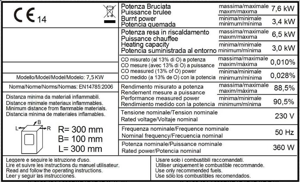
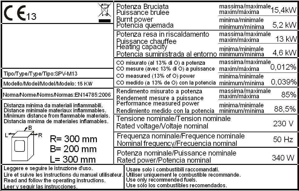
17 07. INSTALLATION INSTRUCTIONS Follow the instructions below before installing your stove. Select the position where the stove is to be installed and: Arrange the connection to the vent pipe for fume extraction Arrange the external air intake (combustion air) Arrange the connection to the earthed mains The electical system of the room where the stove is to be installed must be earthed, otherwise the control board may not work properly. Place the stove on the floor in a convenient position for the connection to the vent pipe and close to the combustion air intake. The appliance must be installed on a floor with an adequate loading-bearing capacity. Should the existing floor not comply with the requirement above, proper measures must be taken (for instance, the installation of a load distribution plate). All the structures which can catch fire if exposed to excessive heat must be protected. Floors made from wood or inflammable materials must be protected using non-combustible materials (e.g. 4mm-thick sheet metal or ceramic glass). The appliance installation must ensure easy access for cleaning the stove, exhaust pipes and vent pipe. This appliance is not suitable to be installed on a shared vent pipe. During normal operation, the stove draws air from the room where it is installed. Therefore, an external air intake must be positioned at the same height of the pipe located on the stove back. Exhaust fume pipes must be suitable for pellet stoves and therefore made from coated steel or stainless steel, with a diameter of 8cm and fitted with adequate gaskets. The combustion air intake (Φ 80mm) must be connected directly to the outside or to adjacent rooms provided they are fitted with external air supply vents (Φ 80mm) and are not used as bedrooms or bathrooms or, whenever a fire hazard exists, as storage rooms, garages, combustible material warehouses, etc. The air vents must be placed in such a way that they cannot be clogged either from the outside or inside and must be protected using a grille, a metal mesh or other suitable means provided they do not reduce the minimum section. If the stove is to be installed in rooms where it is surrounded by combustible materials (e.g. furniture, wood cladding, etc.), the following minimum clearances must be complied with: See stove data plate. During installation, the installer must also take into consideration the convective air sections: the structure housing the appliance must be fitted with ventilation slots. A = 740 cm² B = 366 cm² 16
18 07. INSTALLATION INSTRUCTIONS Besides complying with the minimum clearances set above, we also recommend installing heat-resistant fireproof insulating panels (rock wool, cellular concrete, etc.). We recommend using the following model: Promasil 1000 Classification temperature: 1000 C Bulk density: 245 kg/m 3 Shrinkage at reference temperature, 12 h: 1000 C / 1.3% Cold crushing strength: 1.4 MPa Bending strength: 0.5 MPa Reversible thermal expansion: 5.4x10⁻⁶ m/mk Specific heat capacity: 1.03 Kj/kg K Thermal conductivity λ: 200 C 0.07 W/mK 400 C 0.10 W/mK 600 C 0.14 W/mK 800 C 0.17 W/mK Thickness: 40 mm When working the stove may create a negative pressure inside the room where it is installed. Therefore, it is not possible to have more than one open flame appliance installed in the same room (the type C boilers (room sealed) are the only exception admitted). Make sure that the stove can draw the necessary quantity of combustion air from an open space (i.e. a space without exhaust blowers or providing adequate ventilation) or directly from outside. Do not install the stove in bedrooms or bathrooms. INSTALLAZION CORNER STOVE Pursuant to current regulations on installation, the corner stove must be placed in a well-ventilated place to guarantee efficient combustion and proper functioning. The room must have a volume equal to or higher than 20 m3. An air vent is required to guarantee efficient combustion (40 m3/h air). It can be connected directly to the outside or to adjacent rooms provided they are fitted with external air supply vent ( 80mm) and are not used as a bedroom or bathroom or, whenever a fire hazard exists, as storage room, garage, combustible material warehouse, etc.. The air vents must be placed in such a way that they cannot be clogged either from the outside or inside and must be protected using a grille, a metal mesh or other suitable means provided they do not reduce the minimum cross-section. When working the corner stove may create a negative pressure inside the room where it is fitted. Therefore, it is not possible to have more than one open flame appliance installed in the same room (the type C boilers (room sealed) are the only exception unless provided with their own air vent). The corner stove must be installed far from curtains, armchairs, furniture or other inflammable materials. The corner stove must not be installed in case of explosive atmospheres or in rooms that may become potentially explosive due to the presence of appliances, materials or powders causing gas leaks or catching fire easily from sparks. When installing a corner stove make sure to guarantee adequate clearance from all finishes or beams made from combustible materials, keeping them far from its irradiation area. Moreover, make sure to prevent heat build-up in the recess, which will result in the insert malfunctioning, by guaranteeing the required air space, i.e. by respecting minimum clearances and making ventilation slots with a total surface area of X cm2 cm as shown in the picture below. 17
19 07. INSTALLATION INSTRUCTIONS ATTENTION: 4.5 kw stoves must be fitted with a 1.5 m-long pipe (Φ 80 mm) certified to EN standard. 7,5 kw Slim stoves must be fitted with a 1 m-long pipe (Φ 80 mm) certified to EN standard. 9 kw stoves must be fitted with a 1 m-long pipe (Φ 80 mm) certified to EN standard. 11 kw Slim stoves must be fitted with a 1 m-long pipe (Φ 80 mm) certified to EN standard. 18
20 07. INSTALLATION INSTRUCTIONS INSTALLATION EXAMPLE: EXAMPLE OF INCORRECT INSTALLATION: Exhaust pipes must never be fitted pointing downwards or horizontally so that fumes are discharged directly through the external wall. 19
21 07. INSTALLATION INSTRUCTIONS 12kW SHEET METAL CORNER STOVE After making sure that the insert fits into the recess and there are a socket and a vent pipe 20
22 07. INSTALLATION INSTRUCTIONS 21

23 07. INSTALLATION INSTRUCTIONS 12kW STONE CORNER INSERTS After making sure that the insert fits into the recess and there are a socket and a vent pipe 22
24 07. INSTALLATION INSTRUCTIONS 23


25 08. DATA PLACES 24


26 08. DATA PLACES 25


27 08. DATA PLACES 26
28 09. MICRONOVA ELECTRONICS WITH LED DISPLAY 09.1 Proper functioning and control adjustment devices First connect the stove plug to the mains and load the pellet hopper. Be careful not to empty the entire bag at once. Perform this operation slowly Panel description: BUTTON 1 (P1) Temperature increase: When in temperature setting mode, use this button to increase the thermostat value from a minimum of 6 C to a maximum of 41 C. The selected value appears on the lower display, while the upper display shows the message SET. When modifying user and technician parameters, use this button to increase the parameter value. The selected value appears on the lower display. When in working mode, use this button to visualise the fume temperature on the lower display. BUTTON 2 (P2) - Temperature decrease: When in temperature setting mode, use this button to decrease the thermostat value from a maximum of 41 C to a minimum of 06 C. The selected value appears on the lower display, while the upper display shows the message SET. When modifying user and technician parameters, use this button to decrease the parameter value. The selected value appears on the lower display. When in working mode, use this button to visualise the time on the lower display. BUTTON 3 (P3) - Set/menu: Use this button to access temperature setting and user and technician parameter menu. Press P3 button repeatedly to cycle through all the parameters inside the menu. The upper display visualises the parameter label, while the lower display shows the relevant value. BUTTON 4 (P4) - ON/OFF Unlocking: Hold this button down for two seconds to manually switch the stove on or off respectively depending on its initial status (switched on or off). In case any alarm has blocked the stove, press this button to unlock it and subsequently switch it off. When setting user/technician parameters, use this button to exit the menu at any setting step. BUTTON 5 (P5) - Heat output decrease: When in working mode, use this button to decrease the heat output from 5, maximum value, to 1. The selected value appears on the upper display. BUTTON 6 (P6) - Heat output increase: When in working mode, use this button to increase the heat output from 1, minimum value, to 5. The selected value appears on the upper display. ris/ ECO Temperature reached: When the required temperature is reached, the message ris/ ECO appears on the display. P5 and P6 buttons are disabled automatically. Change the set temperature to enable P5 and P6 buttons again and access the heat output setting. 27
: The LED is on when the UT1 user parameter has a value different from OFF and the weekly or daily programming can be set.")
: The LED flashes whenever the control panel receives a signal from the IR remote control to modify temperature/heat output.")
29 09. MICRONOVA ELECTRONICS WITH LED DISPLAY 09.2 LED indicators Active Chrono LED (L1): The LED is on when the UT1 user parameter has a value different from OFF and the weekly or daily programming can be set. Auger tube ON LED (L2): The LED is on whenever the Auger tube is enabled and the motor, feeding the pellets in the combustion chamber, is working, i.e. during START-UP and WORK mode. Remote control receiver LED (L3): The LED flashes whenever the control panel receives a signal from the IR remote control to modify temperature/heat output. Room thermostat LED (L4): The LED is on whenever the room temperature is higher than the set temperature (external thermostat not in use). If an external thermostat is available, the LED is on whenever the fume temperature exceeds 250 C. Temperature setting LED (L5): The LED flashes when working in the user/technician menu or while setting the temperature The displays Status/Heat Output/Paramenter label Display (D1): It shows the board status during start-up phase. During working mode, it shows the heat output set by the user. When modifying user/technician parameters, it shows the label of the parameter in question. Status/Time/Temperature/Parameter value Display (D2): It shows the board status during start-up phase. During working mode, it shows the temperature set by the user. When modifying user/technician parameters, it shows the value of the parameter in question. 28
30 09. MICRONOVA ELECTRONICS WITH LED DISPLAY 09.4 User functions Stove switching on Hold down P4 for a few seconds to switch on the stove. The display shows that the stove is on. The stove goes into the pre-ventilation/pre-heating phase for 90 seconds, then it enters the pre-load mode for the period of time indicated by Pr45 parameter. Meanwhile, the Auger tube rotates and continues to load pellets. At the end of the period of time set by Pr45 parameter, the system goes into the waiting phase whose duration is defined by Pr46 parameter. Then the loading phase begins at the speed set by Pr04 parameter. The Auger tube ON LED is on indicating that the Auger tube is working. The ignition plug switches off when fume temperature exceeds value under parameter PR13, increasing by a gradient of approx. 3 C / minute Pellet manual loading Press P5 and P6 buttons simultaneously to load the pellets. This function is available only when the stove is switched off and cold Fire on Once fume temperature has reached and exceeded PR13 parameter value, the stove goes into the switching on mode: In this phase emperature stabilises for a period of time set by PR2 parameter. If problems occur during this phase, the stove stops and the following error message is displayed Working mode Dopo che la temperatura dei fumi ha raggiunto e superato il valore contenuto in PR13 e lo ha mantenuto per almeno un tempo PR02, la stufa passa nella modalità lavoro che è quella normale di esercizio. Il display superiore visualizza la potenza impostata con i tasti P5 e P6 e quello inferiore la temperatura ambiente. N.B.: : you can jump directly to working mode by holding down P6 button for approx. 2 seconds. Press P1 button to display fume temperature and exhaust blower speed Changing set heat output When the stove is in working mode, the heat output can be changed by pressing P6 (decrease) buttons. The upper display shows the set heat output. (increase) and P Changing set room temperature Press SET button (P3) to change room temperature and visualise the set room temperature (temperature SET). Press P1 and P2 buttons to increase or decrease, respectively, the temperature value. The new value is saved after approx. 3 seconds and the display goes back to normal. Press P3 button (SET) to visualise the set room temperature (set temperature). Which remains on the display for about 2 seconds Stove switching off Hold down P4 button for approx. 2 seconds to switch off the stove. OFF appears on the upper display, while the lower display shows current time. Room temperature reaches the set value (SET temperature) When the set room temperature value is reached, the stove heat output is automatically set to the minimum value. ECO (Economy) message appears on the upper display and the room thermostat LED switches on. The Auger tube motor stops and the exhaust blower speed increases. The exchanger blower remains on until the fume temperature reaches a value below the preset PR15 value. The exhaust blower switches off after approx. 10 minutes. Depending on the version, it may be necessary to wait the period of time set by Pr73 parameter before switching on the stove again. During the wait, P4 button is inactive and the following message appears asking users to wait until the end of the switching off phase. The same happens whenever the fume temperature exceeds the maximum value set by Pr14 parameter. Once the temperature falls again within the set range, the stove goes back to the normal working mode. 29
31 09. MICRONOVA ELECTRONICS WITH LED DISPLAY Burn pot cleaning When the stove is in the normal working mode, the BURN POT CLEANING mode is activated for the period set by Pr12 parameter at the intervals set by Pr03 parameter Programmable thermostat The programmable thermostat function allows for the programming of the stove automatic switching on and off during the week. Press P3 button twice to enter the programming mode. Press P3 button again to cycle through all the parameters available. Press instead P4 button to exit the programming at any time. The programmable thermostat parameters are listed below: Parameter Description Available values UT01 Current day setting and programmable thermostat enabling/disabling Day1,...Day7; OFF; UT02 Current time setting From 00 to 11 pm UT03 Current time minute setting From 00 to 60 UT04 ONLY FOR TECHNICIANS DO NOT enter any setting UT05 PROGRAMME 1 switching-on time setting From 00:00 to 11:50 pm by 10 UT06 PROGRAMME 1 switching-off time setting From 00:00 to 11:50 pm by 10 UT07 Day selection with stove switching on according to PROGRAMME 1 On/off for days from 1 to 7 UT08 PROGRAMME 2 switching-on time setting From 00:00 to 11:50 pm by 10 UT09 PROGRAMME 2 switching-off time setting From 00:00 to 11:50 pm by 10 UT10 Day selection with stove switching on according to PROGRAMME 2 On/off for days from 1 to 7 UT11 PROGRAMME 3 switching-on time setting From 00:00 to 11:50 pm by 10 UT12 PROGRAMME 3 switching-off time setting From 00:00 to 11:50 pm by 10 UT13 Day selection with stove switching on according to PROGRAMME 3 On/off for days from 1 to 7 UT14 PROGRAMME 4 switching-on time setting From 00:00 to 11:50 pm by 10 UT15 PROGRAMME 4 switching-off time setting From 00:00 to 11:50 pm by 10 UT16 Day selection with stove switching on according to PROGRAMME 4 On/off for days from 1 to 7 Some parameters are described in detail below: D1 Display Day 1 Day 2 Day 3 Day 4 Day 5 Day 6 Day 7 OFF Meaning Monday Tuesday Wednesday Thursday Friday Saturday Sunday Programmable thermostat UT01 Press P1 and P2 buttons to enable the programmable thermostat. Then set the current week day. (Day 7 = Sunday). Press P1 and P2 buttons and then select OFF to disable the programmable thermostat. PROGRAMME 1 SWITCHING ON/OFF (morning) UT05 UT06 Set the PROGRAMME 1 stove switching on and off times by modifying these two parameters. Their value can be set if UT01 parameter is set to the daily or weekly mode. UT07 Set the days when PROGRAMME 1 (ON) is active and the days when IT IS NOT (OFF) by modifying UT07. This parameter is active when UT01 is set to the weekly mode. Press P2 button to select the day of the week and then enable (ON)/disable (OFF) stove switching on/off according to PROGRAMME 1 by means of P1 button. In the example below, the stove switches on only on Saturdays and Sundays according to PROGRAMME 1 (morning). Day 1 Monday Day 2 Tuesday Day 3 Wednesda Day 4 Thursda Day 5 Friday Day 6 Saturda Off 1 Off 2 Off 3 Off 4 Off 5 On 6 On 7 Day 7 Sunday 30
32 09. MICRONOVA ELECTRONICS WITH LED DISPLAY PROGRAMME 2 SWITCHING ON/OFF (afternoon) UT08 - UT9 Set the PROGRAMME 2 stove switching on and off times by modifying these two parameters. Their value can be set if UT01 parameter is set to the daily or weekly mode. UT010 Set the days when PROGRAMME 2 (ON) is active and the days when IT IS NOT (OFF) by modifying UT10. This parameter is active when UT01 is set to the weekly mode. Press P2 button to select the day of the week and then enable (ON)/disable (OFF) stove switching on/off according to PROGRAMME 2 by means of P1 button In the example below, the stove switches on in the afternoon only on working days. PROGRAMME 2 SWITCHING ON/OFF (afternoon) Day 1 Monday Day 2 Tuesday Day 3 Wednesda Day 4 Thursda Day 5 Friday Day 6 Saturda Day 7 Sunday On 1 On 2 On 3 On 4 On 5 Off 6 Off 7 Example: TIMER PROGRAMMING UT CURRENT DAY SETTING (DAY 7 = SUNDAY) PROGRAMME1 UT st SWITCHING ON ( e.g. 07:00am) UT st SWITCHING OFF TIME ( e.g. 09:00am) UT DAY CONFIRMATION ( e.g. Day 1 -off / Day2-off/Day3-off/Day4-off/Day5-off/Day6-on/Day7-on ) PROGRAMME 2 UT nd SWITCHING ON UT nd SWITCHING OFF TIME UT DAY CONFIRMATION ( e.g. 06:00pm) ( e.g. 12:00am) ( e.g. Day 1-on / Day2-on/Day3-on/Day4-on/Day5-on/Day6-off/Day7-off) 09.5 Alarms The board is fitted with a control system that shows on the display where the failure occurred to inform the user in case of malfunctioning. Press P4 button to CLEAR the message on the display. Alarm Fume temperature sensor Fume overheating Ignition failure Power outage General safety thermostat Clogged chimney Alarm Display shows ALARM SOND FUMI ALARM HOT TEMP ALARM NO FIRE ALARM NO RETE ALARM SIC ALARM DEP Display shows The meaning of these alarm messages is explained in detail below Fume temperature sensor alarm The alarm is triggered when the fume temperature sensor is damaged or disconnected. The exhaust and exchanger blower speed is increased to its maximum value and the Auger motor is switched off, interrupting pellet loading. The blower remains on for approximately 10 minutes Fume overheating alarm The alarm is triggered whenever the fume sensor detects a temperature exceeding 220 C. The message alarm hot temp appears on the display. The exhaust blower speed is increased to its maximum value and the Auger tube motor is switched off, interrupting pellet loading. The blower remains on for approximately 10 minutes.. 31

33 09. MICRONOVA ELECTRONICS WITH LED DISPLAY Ignition failure alarm The alarm is triggered at the second ignition failure, i.e. when the stove does not reach the required ignition temperature twice (a 3 C/ minute gradient is necessary). The message alarm no fire appears on the display. The stove enters the switching off phase which is completed in approximately 10 minutes, as with the other alarms described above Stove switching-off during working mode alarm The alarm is triggered when the flame goes out and the fume temperature falls below the stove minimum working threshold. The message alarm no fire appears on the display and the stove switches off Negative pressure alarm The alarm is triggered when the chimney or the fume outlet are clogged General safety thermostat alarm If the general safety thermostat detects a value exceeding the trigger threshold, it immediately switches off the Auger tube (to which it is connected in series), while the control board acquires this change in status through the AL1 clamp in CN4. The message ALARM SIC is displayed. Unscrew the black cap on the back of the stove and press the button to reset the contact No electrical supply alarm The lack of electrical supply during the work, stops the functioning of electrical components of the stove. When the electrical supply is restored the stove shows the alarm NO RETE and it is necessary to switch on again. Then after waiting for a cooling period, COOL FIRE, till when the smoke temperature goes below the limit temperature set at parameter Pr Damage exhaust blower alarm In case the exhaust blower (smoke fan) gets broken, the stove switches off and it is displayed the message ALARM FAN FAIL Stoves with ducting system (only 14.5 kw models) Fan no. 2 speed setting To set the speed of the second exchanger, press P3 (SET) button and then P6 repeatedly to select the desired value. 32


34 10. MICRONOVA ELECTRONICS WITH LCD DISPLAY 10.1 Proper functioning and control adjustment devices Control panel The control panel shows the information concerning the stove status. Several types of data can be displayed and the settings available according to the access level can be modified by entering the menu. Depending on the selected mode and on their position on the display, the data visualised may acquire different meanings. Figure 2 shows an example with the stove switched off or on. time clock room temperature status dialogue heat output fig.2 Figure 3 describes the meaning of the status indicators appearing on the display left side. When one of the devices included in the list is activated, the relevant segment on the display status area switches on. chrono ignition plug auger tube exhaust blower exchanger not used alarm fig.3 input menu level status dialogue fig.4 Figure 4 describes the position of the messages visualised during working parameter programming or setting phase. In particular: 1. The input area shows the entered programming values 2. The menu level area displays the current menu level. See chapter dedicated to menu. 33

35 10. MICRONOVA ELECTRONICS WITH LCD DISPLAY Panel description BUTTON 1 (P1) - Temperature increase: When in programming mode, use this button to modify/increase the selected menu value. When in working mode/switched off, use instead this button to increase the room thermostat temperature value. BUTTON 2 (P2) - Temperature decrease: When in programming mode, use this button to modify/decrease the selected menu value. When in working mode/switched off, use instead this button to decrease the room thermostat temperature value. BUTTON 3 (P3) - Set/menu: Use this button to access temperature setting and user and technician parameter menu. After entering the menu, use this button to access the next sub-menu or set the value and move to the next menu item when in programming mode. BUTTON 4 (P4) - ON/OFF Unlocking: Hold this button down for two seconds to manually switch the stove on or off respectively depending on its initial status (switched on or off). Should have any alarm blocked the stove, press this button to unlock it and subsequently switch it off. After entering the menu or during the programming phase, use this button to access the upper menu level. Any change is automatically saved BUTTON 5 (P5) - Heat output decrease: When in working mode, use this button to decrease the heat output value. In menu mode, use this button to move to the next menu item or, in programming mode, to go back to the subsequent sub-menu item. Any change is automatically saved. BUTTON 6 (P6) - Heat output increase: When in working mode, use this button to modify the exchanger speed. In menu mode, use this button to go back to the previous menu item or, in programmino mode, to go back to the previous sub-menu item. Any change is automatically saved Menu Press P3 (MENU) button to access the menu. It includes several items and levels to access settings and control board programming. The menu items providing access to the technical setting are protected by access code User Menu The table below briefly describes the menu structure, focussing in particular on the functions available to users. The menu item 01-fan adjustment is available only if the corresponding function was enabled. 34
36 10. MICRONOVA ELECTRONICS WITH LCD DISPLAY level 1 level 2 level 3 level 4 value 01 fan adjustment select value 02 - time clock setting 01 - day week day 02 - hours hour 03 - minutes minute 04 - day day month 05 - month month 06 - year year 03 chrono setting 01 enable chrono 01 - enable chrono on/off 02 day programming 01 day chrono on/off 02 - start 1 day hour 03 - stop 1 day hour 04 - start 2 day hour 05 - stop 2 day hour 03 week programming 01 week chrono on/off 02 - start prog 1 hour 03 - start prog 1 hour 04 - Monday prog 1 on/off 05 - Tuesday prog 1 on/off 06 - Wednesday prog 1 on/off 07 - Thursday prog 1 on/off 08 - Friday prog 1 on/off 09 - Saturday prog 1 on/off 10 - Sunday prog 1 on/off 11 - start prog 2 hour 12 - stop prog 2 hour 13 - Monday prog 2 on/off 14 - Tuesday prog 2 on/off 15 - Wednesday prog 2 on/off 16 - Thursday prog 2 on/off 17 - Friday prog 2 on/off 18 - Saturday prog 2 on/off 19 - Sunday prog 2 on/off 20 - start prog 3 hour 21 - stop prog 3 hour 22 - Monday prog 3 on/off 23 - Tuesday prog 3 on/off 24 - Wednesday prog 3 on/off 25 - Thursday prog 3 on/off 26 - Friday prog 3 on/off 27 - Saturday prog 3 on/off 28 - Sunday prog 3 on/off 35

37 10. MICRONOVA ELECTRONICS WITH LCD DISPLAY 04 select language level 1 level 2 level 3 level 4 value 04 - week-end program 29 - start prog 4 hour 30 - stop prog 4 hour 31 - Monday prog 4 on/off 32 - Tuesday prog 4 on/off 33 - Wednesday prog 4 on/off 34 - Thursday prog 4 on/off 35 - Friday prog 4 on/off 36 - Saturday prog 4 on/off 37 - Sunday prog 4 on/off 01 - week-end chrono 02 - start stop start stop Italian set 02 - French set 03 - English set 04 - German set 05 - stand-by mode on/off 06 - buzzer on/off 07 initial load set 08 stove status Menu 01-fan adjustment Use this function to independently adjust the two additional blowers. The settings available for each blower are listed in the table below. Press P1 (fan 2) and P2 (fan 3) to select setting. setting blower 2 blower 3 A corresponding to the selected heat output corresponding to the selected heat output 0 disabled fan disabled fan 1 Pr57 fixed speed Pr62 fixed speed 2 Pr58 fixed speed Pr63 fixed speed 3 Pr59 fixed speed Pr64 fixed speed 4 Pr60 fixed speed Pr65 fixed speed 5 Pr61 fixed speed Pr66 fixed speed menu level dialogue fan no. 3 setting fan no. 2 setting 36
38 10. MICRONOVA ELECTRONICS WITH LCD DISPLAY Menu 02 - time clock setting Use this function to set current time and date. The control board is equipped with a lithium battery guaranteeing the internal time clock a 3/5 year-long life. input menu level dialogue Menu 03 - chrono setting Sub-menu enable chrono The programmable thermostat functions can be disabled and enabled. input menu level dialogue Sub-menu daily program The daily programmable thermostat functions can be enabled, disabled and set. input menu level dialogue It is possible to set two on/off times defined by the times set according to the table below. If the value is set to OFF, the time clock ignores the control. setting meaning available values START 1 switchin on time time - OFF STOP 1 switching off time time - OFF START 2 switchin on time time - OFF STOP 2 switching off time time - OFF 37
39 10. MICRONOVA ELECTRONICS WITH LCD DISPLAY Sub-menu weekly program The weekly programmable thermostat functions can be enabled, disabled and set. input menu level dialogue The weekly programmer consists of 4 independent programmes which can be combined together in different ways. The weekly programmer can be enabled or disabled. Moreover, if the time is set to OFF, the time clock ingnores the corresponding control. N.B.: set the programming carefully in order to avoid overlapping of switching on and/or off times of different programmes on the same day. PROGRAMME 1 menu level setting meaning available values START PROG 1 switchin on time time - OFF STOP PROG 1 switching off time time - OFF MONDAY PROG 1 on/off TUESDAY PROG 1 on/off WEDNESDAY PROG 1 on/off THURSDAY PROG 1 on/off FRIDAY PROG 1 on/off SATURDAY PROG 1 on/off SUNDAY PROG 1 on/off PROGRAMME 2 menu level setting meaning available values START PROG 2 switching on time ora - OFF STOP PROG 2 switching off time ora - OFF MONDAY PROG 2 on/off TUESDAY PROG 2 on/off WEDNESDAY PROG 2 on/off THURSDAY PROG 2 on/off FRIDAY PROG 2 on/off SATURDAY PROG 2 on/off SUNDAY PROG 2 on/off reference day reference day PROGRAMME 3 menu level setting meaning available values START PROG 3 switching on time time - OFF STOP PROG 3 switching off time time - OFF MONDAY PROG 3 on/off TUESDAY PROG 3 on/off WEDNESDAY PROG 3 on/off THURSDAY PROG 3 on/off FRIDAY PROG 3 on/off SATURDAY PROG 3 on/off SUNDAY PROG 3 on/off reference day 38

40 10. MICRONOVA ELECTRONICS WITH LCD DISPLAY PROGRAMME 4 menu level setting meaning available values START PROG 4 switching on time time - OFF STOP PROG 4 switching off time time - OFF MONDAY PROG 4 on/off TUESDAY PROG 4 on/off WEDNESDAY PROG 4 on/off THURSDAY PROG 4 on/off FRIDAY PROG 4 on/off SATURDAY PROG 4 on/off SUNDAY PROG 4 on/off Sub-menu week-end program The programmable thermostat functions can be enabled, disabled and set for the week-end (days 5 and 6, or Saturday and Sunday). reference day input menu level dialogue TIP: if you still do not know exactly the result you want to obtain, enable only one programme at a time to avoid confusion and unwanted stove switching on and off. Disable the daily programme if you want to use the weekly programme. If you use the weekly programme for 1, 2, 3 and 4 programmes, never enable the week-end programme. Always disable the weekly programme before enabling the week-end programme Menu 04 Select language Use this function to select one of the languages available. menu level dialogue Menu 05 - stand-by mode If you select the STAND-BY mode, the stove switches off after a period, set by Pr44, during which the room temperature remained at a value higher than the SET temperature. Only if the following condition occurs - TSET < (Tambiente - Pr43), it is then possible to switch the stove back on Menu 06 - buzzer mode Set it to OFF to disable the buzzer. 39


41 10. MICRONOVA ELECTRONICS WITH LCD DISPLAY Menu 07 - initial load Use this function to load pellets for a period of 90 seconds when the stove is switched off and cold. Press P1 button to start and P4 button to stop. timer heat output room temperature dialogue Menu 08 - stove status This function displays the current status of all the devices connected to the stove. A few examples are included in the following pages. timer 1 time for ignition page 3 page 2 page 1 status operational staus alarm delay exhaust blower speed fume temperature exchanger no. 2 an3 status current heat output status exchanger no. 2 speed operational status exchanger no. 3 speed status ongoing alarm 40


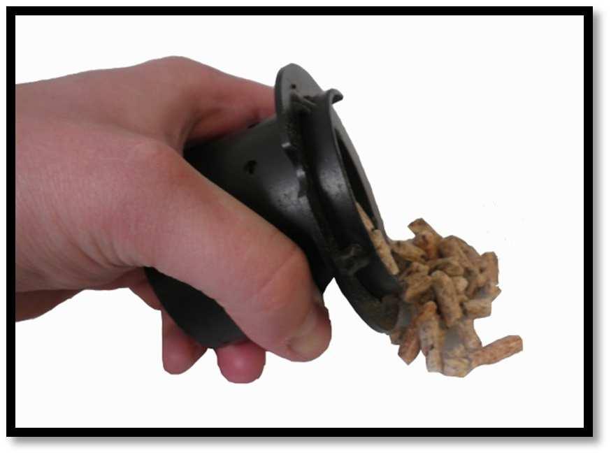
42 10. MICRONOVA ELECTRONICS WITH LCD DISPLAY Menù 09 Kind of fuel BURNER FOR PELLET BURNER FOR WALNUT SHELL Important: do not inter change the two different bottom of the burner Choise of the kind of fuel from the main menù. - Kind of fuel 1 = PELLET - Kind of fuel 2 = NOCCIOLINO (WALNUT SHELL) 10.3 User functions Standard functioning of a control board properly installed on a forced air pellet stove is described below with reference to the functions available to users. The indications listed below refer to a control board fitted with programmable thermostat. The technical setting mode is described in detail in the following sections. Before switching on the stove, the control board display is as in figure 16. time clock room temperature dialogue heat output Stove switching on fig. 16 Hold down P4 for a few seconds to switch on the stove. The display shows the message as in Figure 17 when the stove is on. time clock room temperature dialogue heat output fig Start-up phase The stove performs all the steps of the start-up phase according to the parameters concerning its levels and times Ignition failure The alarm is triggered when, after the period of time set by Pr01, the fume temperature has not reached the minimum value admitted (Pr13 parameter) with a gradient equal to 2 C/min. 41
43 10. MICRONOVA ELECTRONICS WITH LCD DISPLAY Working mode At the end of the start-up phase, if no problems occurred, the stove enters its normal working mode. Exchangers are enabled if the fume temperature is higher than Pr15. Exchangers no.2 and 3 start working only if they were previously enabled. time clock room temperature fig Changing set room temperature Press P1 and P2 buttons to change the room temperatture. The display shows the current SET temperature value as in figure 19. set value dialogue heat output fig External thermostat/programmable thermostat If you want to use an external programmable thermostat, connect it to the TERM clamps (connector CN7 pin 7-8). external thermostat: set the stove SET temperature to 7 C. external programmable thermostat: set the stove SET temperature to 7 C and disable the chrono functions from menu. The stove external thermostat is enabled when the contact is closed with stove on Room temperature reaches set value (SET temperature) When the set room temperature value is reached or the fume temperature has reached the Pr13 value, the stove heat output is set automatically to the minimum value (MODULATION mode). See figure 20 time clock dialogue room temperature dialogue heat output fig. 20 If the stove is in the STAND-BY mode, it switches off after the period of time set by Pr44 and after reaching the SET temperature. If the following condition occurs - Tambiente > (TSET + Pr43), it is then possible to switch the stove back on. 42
44 10. MICRONOVA ELECTRONICS WITH LCD DISPLAY Burn pot cleaning When the stove is in the working mode, the BURN POT CLEANING mode is activated for the period set by Pr12 parameter at the intervals set by Pr03 parameter. time clock room temperature dialogue heat output Stove switching off fig. 21 Hold down P4 button for approx. 2 seconds to switch off the stove. The Auger tube stops immediately and the exhaust blower reaches its maximum speed value. The FINAL CLEANING phase is performed. At the end of the period of time set by Pr39, when the fume temperature has reached a value below Pr13 parameter, the exhaust blower stops. time clock room temperature dialogue heat output fig Stove switched off time clock room temperature dialogue heat output fig
45 10. MICRONOVA ELECTRONICS WITH LCD DISPLAY Switching on the stove again It will be possible to switch the stove back on only at the end of the safety period of time set by Pr38 and if the fume temperature has reached a value below Pr13. time clock room temperature dialogue heat output 10.4 What happens in case of fig Pellet ignition failure If pellets do not ignite, the display shows the alarm message NO ACC as shown in figure 25. fig Power outage Pr48 = 0 When the power is resumed after an outage, the stove enters the FINAL CLEANING phase and waits until the fume temperature reaches a value below Pr13. fig. 26 Pr48 = T seconds After a power outage, one of the following conditions may occur depending on the stove previous status: previous status outage duration new status switched off any switched off ignition < T ignition pellet loading without pre-load < T pellet loading pellet loading with pre-load any switching off waiting for flame < T waiting for flame working mode < T working mode burn pot cleaning < T burn pot cleaning switching off < T switching off If the power outage duration is longer than T, the stove switches off. 44
46 10. MICRONOVA ELECTRONICS WITH LCD DISPLAY 10.5 Alarms In case of malfunctioning the control board reports the problem and activates various procedures depending on the type of alarm. Possible alarm messages are listed below. Cause Display shows Fume temperature sensor ALARM SOND FUMI Fume overheating ALARM HOT TEMP Ignition failure ALARM NO FIRE Switches off when in working mode ALARM NO FIRE Power outage COOL FIRE (vedi par. 9.2) Auger tube safety pressure switch General safety thermostat Damaged exhaust blower ALARM DEP FAIL ALARM SIC FAIL ALARM FAN FAIL In case of alarm, the stove is immediately switched off. The alarm status is reached after a set period of time (Pr11) and can be cleared by pressing P4 button Fume temperature sensor alarm The alarm is triggered when the fume temperature sensor is not working properly or is disconnected. During the alarm, the stove switches off. fig Fume overheating alarm The alarm is triggered when the fume sensor registers a temperature exceeding 280 C. The message shown in figure 28 appears. The stove switching-off phase starts immediately. fig Ignition failure alarm The alarm is triggered whenever ignition fails. The stove switching-off phase starts immediately. fig
47 10. MICRONOVA ELECTRONICS WITH LCD DISPLAY Stove switching-off during working mode alarm The alarm is triggered when, during normal working mode, the flame goes out and the fume temperature falls below the minimum threshold set by Pr13 parameter (see figure 30). The stove switching-off phase starts immediately. fig Auger tube safety pressure switch alarm If the pressure switch (meter pressure) detects a value below the trigger threshold, it immediately switches off the Auger tube (to which it is connected in series) while the control board acquires this change in status through the AL2 clamp in CN4. The message Alarm Dep Fail appears on the display and the stove is immediately switched off. fig General thermostat alarm If the general safety thermostat detects a value exceeding the trigger threshold, it immediately switches off the Auger tube (to which it is connected in series), while the control board acquires this change in status through the AL1 clamp in CN4. The message ALARM SIC FAIL appears on the display and the stove is immediately switched off. Unscrew the black cap on the back of the stove and press the button to reset the contact Damaged exhaust blower alarm fig. 32 Whenever the exhaust blower stops working properly, the stove switches off immediately and the message ALARM FAN FAIL appears on the display.the stove switching off phase starts immediately. fig

48 11. N100 MICRONOVA ELECTRONICS WITH 3-BUTTON LED DISPLAY 11.1 Proper functioning and control adjustment devices Control panel The control board can be managed by simply pressing a few buttons on the control panel. A display and the LED indicators inform about the stove operational status. When in programming mode all the parameters that can be modified using the buttons are shown on the display. Chrono LED Heat output setting LED Room temperature setting LED Status/heat output/parameter display ON/OFF LED OFF P1 button decrease/ menu/room temperature setting P2 button increase/ stove status/heat output setting Alarm LED P3 button ON/OFF/ exit/confirm Auger tube/ exchangerpump/ ignition plug LED LED indicators LED ROOM TEMP SETTING HEAT OUTPUT SETTING CHRONO ALARM IGNITION PLUG AUGER TUBE ON EXCHANGER-PUMP ON\OFF Meaning when switched on Room temperature value setting Heat output value setting Chrono enabled Stove in alarm Ignition plug switching on Auger tube moving Exchanger \ pump switched on Working status Display display function status display shows OFF OFF+ROOM TEMPERATURE DISPLAY status heat output parameter label SWITCHING ON FEEDING WORKING ACCENDE+ROOM TEMPERATURE CARICA PELLET ROOM TEMPERATURE+HEAT OUTPUT+TIME PROGRAMMING SELECTED PARAMETER 47
49 11. N100 MICRONOVA ELECTRONICS WITH 3-BUTTON LED DISPLAY 11.2 Menu Hold P1 button down to access the menu. It includes several items and levels to access settings and control board programming User Menu The table below briefly describes the menu structure, focusing in particular on the functions available to users. level 1 level 2 level 3 value M1 time clock setting - Week day M-T-W-Th-F-S-Su T i m e c l o c k h o u r s 0-11 Time clock mi nutes 0-59 Time clock day 1-31 T i me clock month 1-12 T i me clock year M2 Chrono setting M2-1 - enable chrono 01 enable chrono on/off M2-2 daily programming 01 day chrono on/off 02 - start 1 day OFF-0-11:50 pm 03 - stop 1 day OFF-0-11:50 pm 04 - start 2 day OFF-0-11:50 pm 05 - stop 2 day OFF-0-11:50 pm M2-3 - weekly programming 01 - weekly programming on/off 02 - start Prog 1 OFF-0-11:50 pm 03 - stop Prog 1 OFF-0-11:50 pm 04 Monday Prog 1 on/off 05 - Tuesday Prog 1 on/off 06 - Wednesday Prog 1 on/off 07 - Thursday Prog 1 on/off 08 - Friday Prog 1 on/off 09 - Saturday Prog 1 on/off 10 - Sunday Prog 1 on/off 11 - start Prog 2 OFF-0-11:50 pm 12 - stop Prog 2 OFF-0-11:50 pm 13 - Monday Prog 2 on/off 14 - Tuesday Prog 2 on/off 15 - Wednesday Prog 2 on/off 16 - Thursday Prog 2 on/off 17 - Friday Prog 2 on/off 18 - Saturday Prog 2 on/off 19 - Sunday Prog 2 on/off 20 - start Prog 3 OFF-0-11:50 pm 21 - stop Prog 3 OFF-0-11:50 pm 22 - Monday Prog 3 on/off 23 - Tuesday Prog 3 on/off 24 - Wednesday Prog 3 on/off 25 - Thursday Prog 3 on/off 26 - Friday Prog 3 on/off 27 - Saturday Prog 3 on/off 28 - Sunday Prog 3 on/off 29 - start Prog 4 OFF-0-11:50 pm 30 - stop Prog 4 OFF-0-11:50pm 31 - Monday Prog 4 on/off 32 - Tuesday Prog 4 on/off 33 - Wednesday Prog 4 on/off 34 - Thursday Prog 4 on/off 35 - Friday Prog 4 on/off 36 - Saturday Prog 4 on/off 37 - Sunday Prog 4 on/off 48
50 11. N100 MICRONOVA ELECTRONICS WITH 3-BUTTON LED DISPLAY M3 select language M4 - stand-by MS Buzzer M6 First load M7 Stove status M8 - Technician settings M9 - Exit M2-4 weekend programming 01 weekend chrono on/off 02 - start weekend 1 OFF-0-11:50 pm 03 - stop weekend 1 OFF-0-11:50pm 04 - start weekend 2 OFF-0-11:50 pm 05 - stop weekend 2 OFF-0-11:50 pm M2-5 - exit set 01 Italian set 02 English set 03 French set 03 - German set 01 - stand by on/off 01 buzzer On/off 01 First load Stove status 01 Auger tube status info 02 T minutes info 03 Thermostat status Info 04 Fume status Info 05 Exhaust blower rev. status rpm Info 01 - Password set 01 - Exit set Menu M01 time clock setting Use this function to set current time and date. The control board is equipped with a lithium battery guaranteeing the time clock a life longer than 3/5 years. Hold P1 button down for 2 seconds to access the general programming menu. Press P1 (decrease) or P2 (increase) button to select M1 item. The message M1 set orologio will scroll on the display. (figure 13a) MI Figure 13 a LUN Figure 13 b 49
.")
, month (figure 13f) and year (figure 13g) by")

51 11. N100 MICRONOVA ELECTRONICS WITH 3-BUTTON LED DISPLAY Select the desired day and press P3 button (figure 13b). Then set the hour (figure 13c), minutes (figure 13d), day (figure 13e), month (figure 13f) and year (figure 13g) by pressing P1 (decrease) and P2 (increase) buttons. Press P3 button to confirm the desired value. ORE MIN GIO MES ANN 50
52 11. N100 MICRONOVA ELECTRONICS WITH 3-BUTTON LED DISPLAY Menu M02 chrono setting Sub-menu M2 1 Enable chrono All programmable thermostat functions can be disabled and enabled by means of the menu that appears on the display "M2 set crono (M2 chrono set). Press P3 button and then P1 or P2, for selecting On or Off respectively, to enable the programmable thermostat. Press P3 button to confirm. (figure 14a) ABIL Sob-menu M2-2 Daily programming figure 14a After selecting menu M2-2 day programm, press P3 button to scroll through the different programming parameters available for the daily programmable thermostat, including the possibility of enabling it (figure 14b). CRO figure 14b It is possible to set two on/off times (the first with START1 Day and STOP1 Day and the second with START2 Day and STOP2 Day) defined by the times set according to the table below. If the value is set to OFF, the time clock ignores the control. Use P1 (decrease) and P2 (increase) buttons to modify the value and P3 to confirm. DAILY PROGRAMMING Menu level setting meaning Available values M DAY CHRONO Enable daily chrono ON/OFF M START 1 Day Switching-on time OFF-0-11:50 M STOP 1 Day Switching-off time OFF-0-11:50 M START 2 Day Switching-on time OFF-0-11:50 M STOP 2 Day Switching-off time OFF-0-11:50 Sub-menu M2-3 Weekly programming The weekly programmable thermostat functions can be enabled/disabled and set using the menu M2-3 Program Settim- (M2-3 Week Programm). The weekly programming function features 4 independent programmes. Moreover, if the time is set to OFF, the time clock ignores the corresponding control. The weekly programming function is briefly described in the tables below. Press P3 to confirm the value and pass to the following function. Hold P3 button down to exit the menu. ENABLING WEEKLY CHRONO menu level setting meaning available values M WEEKLY CHRONO Enable weekly chrono ON/OFF 51
53 11. N100 MICRONOVA ELECTRONICS WITH 3-BUTTON LED DISPLAY PROGRAMME 1 menu level setting meaning available values M START PRG 1 switching-on time OFF-0-11:50 M STOP PRG 1 switching-off time OFF-0-11:50 M MONDAY PRG 1 on/off M TUESDAY PRG 1 on/off M WEDNESDAY PRG 1 on/off M THURSDAY PRG 1 on/off M FRIDAY PRG 1 on/off M SATURDAY PRG 1 on/off M SUNDAY PROG 1 on/off PROGRAMME 2 menu level setting meaning available values M START PRG 2 switching-on time OFF-0-11:50 M STOP PRG 2 switching-off time OFF-0-11:50 M MONDAY PRG 2 on/off M TUESDAY PRG 2 on/off M WEDNESDAY PRG 2 on/off M THURSDAY PRG 2 on/off M FRIDAY PRG 2 on/off M SATURDAY PRG 2 on/off M SUNDAY PROG 2 on/off PROGRAMME 3 menu level setting meaning available values M START PRG 3 switching-on time OFF-0-11:50 M STOP PRG 3 switching-off time OFF-0-11:50 M MONDAY PRG 3 on/off M TUESDAY PRG 3 on/off M WEDNESDAY PRG 3 on/off M THURSDAY PRG 3 on/off M FRIDAY PRG 3 on/off M SATURDAY PRG 3 on/off M SUNDAY PROG 3 on/off PROGRAMME 4 menu level setting meaning available values M START PRG 4 switching-on time OFF-0-11:50 M STOP PRG 4 switching-off time OFF-0-11:50 M MONDAY PRG 4 on/off M TUESDAY PRG 4 on/off M WEDNESDAY PRG 4 on/off M THURSDAY PRG 4 on/off M FRIDAY PRG 4 on/off M SATURDAY PRG 4 on/off M SUNDAY PROG 4 on/off 52
54 11. N100 MICRONOVA ELECTRONICS WITH 3-BUTTON LED DISPLAY Sub-menu M2-4 weekend programming The programmable thermostat functions can be enabled/disabled and set for the weekend (days 6 and 7, or Saturday and Sunday). Select crono fine-sett (weekend chrono) item and press P3 button to enable it. Then select on using P1 (decrease) or P2 (increase) button. Set Start 1 fine - sett (Start 1 weekend)and Stop 1 fine sett (Stop 1 weekend) times to define the stove operating period concerning Saturday and (Start 2 weekend) and (Stop 2 weekend) times to define the stove operating period concerning Sunday. WEEKEND PROGRAMMING menu level setting meaning available values M WEEKEND CHRONO Enable weekend chrono ON/OFF M START 1 WEEKEND switching-on time OFF-0-11:50 M STOP 1 WEEKEND switching-off time OFF-0-11:50 M START 2 WEEKEND switching-on time OFF-0-11:50 M STOP 2 WEEKEND switching-off time OFF-0-11: Menu M03 select language Use this function to select one of the languages available (figure 15). Press P2 (increase) and P1 (decrease) buttons to scroll through the options and press P3 button to confirm. LIN figure Menu M04 stand-by Use this function to enable or disable the Stand-by mode (figure 16). Press P3 button to select menu M4 and then P1 (decrease) or P2 (increase) button to select the ON or OFF status. Refer to the section concerning the stand-by mode for more details on its functioning. STA figure Menu M05 buzzer mode Use this function to enable or disable the control board buzzer during alarms (figure 17). Press P1 or P2 button to enable or disable this function and P3 button to confirm. CIC figure 17 53
55 11. N100 MICRONOVA ELECTRONICS WITH 3-BUTTON LED DISPLAY Menu M06 first load This function is available only when the stove is switched OFF. It allows the Auger tube to be loaded upon the first stove start-up when the pellet hopper is empty. After selecting menu M6, the message "Premere più" (figure 18a) will scroll on the display. Then press P2 (increase). The exhaust blower switches on at the maximum speed and the Auger tube (Auger tube LED on) starts working. They will switch off once the period of time indicated on the display (figure 18b) has elapsed or after pressing P3 button. PRE figure figure 18b Menu M07 stove status After entering menu M7 by pressing P3 button, the status of a few parameters with stove in working mode scrolls on the display. The table below contains an example of the values scrolling on the display together with their meaning. Displayed status meaning 3.1 Auger tube pellet feeding status 52 Max. time for ignition phase Toff Thermostat status 106 Fume temperature 1490 Exhaust blower speed Menu M08 technician settings This menu item is reserved to the stove installer. After entering the password (figure 19), P1 (decrease) and P2 (increase) buttons allow all the stove working parameters to be set. CHI figure Menù M09 exit Select this item by pressing P3 button (figure 20) to exit the menu and go back to the previous status. USC figure 20 54
56 11. N100 MICRONOVA ELECTRONICS WITH 3-BUTTON LED DISPLAY 11.3 User functions Standard functioning of a control board properly installed on a forced air pellet stove is described below with reference to the functions available to users. Before switching on the stove, the control board display is as in figure 3. OFF figure Stove switching on Hold P3 button down for a few seconds to switch on the stove. The message "Accende" (as in figure 4) appears on the display and the ON/OFF LED starts flashing if the stove has successfully switched on. This phase lasts for the period of time set by PR0 1 parameter. During this phase the stove goes into the pre-heating status: the ignition plug (as indicated by the relevant LED) and the exhaust blower switch on. (figure 4) Any problem detected during the switching-on phase is indicated on the display and the stove goes into the alarm status. ACC figure Pellet feeding The pellet feeding phase starts after approx. 1 minute: the message "Carica pellet" scrolls on the display and the ON/OFF LED starts flashing. During the first stage the Auger tube feeds the pellets to the burn pot during a period of time set by PR40 parameter (Auger tube LED on), the exhaust blower speed is set by PR42 parameter and the ignition plug is still on (ignition plug LED on). During the second stage, once the period of time set by PR40 parameter has elapsed, the Auger tube switches off (Auger tube LED off) during a period of time set by PR4 1 parameter, while the exhaust blower speed remains as in the previous status. The ignition plug is still on. In case of ignition failure at the end of this phase, the Auger tube switches back and remains on during the period of time set by PR04 parameter, the exhaust blower speed is set by PR1 6 parameter and the ignition plug is still on. (figure 5) CAR figure 5 55
57 11. N100 MICRONOVA ELECTRONICS WITH 3-BUTTON LED DISPLAY Fire on Once fume temperature has reached and exceeded PR13 parameter value, the stove goes into the ignition mode: the message "Fuoco presente" appears on the display and the ON/OFF LED starts flashing. During this phase the temperature remains stable for a period of time preset by PR02 parameter. The exhaust blower speed is set by PR17 parameter, the Auger tube remains on for a period of time set by PR05 parameter (Auger tube LED flashing) and the ignition plug is off (ignition plug LED off). (figure 6) Any problem during this phase will cause the control board to stop and the stove to go into error state. FUO figure Working mode Once fume temperature has reached and exceeded PR13 parameter value, maintaining it for the period of time set by PR02 parameter, the stove enters the normal working mode. The message "Lavoro" appears on the display and the ON/OFF LED is on. Hold P2 button down to set the heat output and press P1 button to set the room temperature. (figure 7a) If fume temperature reaches the threshold set by PR1 5 parameter, the air exchanger fan will switch on (as the exchanger LED). LAV figure 7a During this phase, after a period of time set by PR03 parameter, the stove cleans the burn pot. The message "Pul-braciere" scrolls on the display, the Auger tube is on (as the relevant LED) at a speed set by PR09 parameter and the exhaust blower at a speed set by PR08 parameter. (figure 7b) Once the period of time set by PR12 parameter has elapsed, the stove goes back to the working mode. PUL- figure 7b Changing set heat output During stove normal operation ( Lavoro working mode), the heat output can be changed by using P2 button (Heat output setting LED on). Press P2 button again to increase the heat output and P1 button to decrease it. The display will show the set heat output. (figure 8) Do not press any button for 5 seconds or press P3 button to exit the setting mode. Pot3 figure 8 56
58 11. N100 MICRONOVA ELECTRONICS WITH 3-BUTTON LED DISPLAY Changing set room temperature Press P1 button to change the set room temperature. The display shows the set room temperature (SET temperature value). Press P1 and P2 buttons to decrease or increase, respectively, the temperature value. The value is saved after approx. 5 seconds and the display goes back to normal. Otherwise, press P3 to exit. (figure 9) 22,5 c figure Room temperature reaches set value (SET temperature value) Once the set room temperature value has been reached, the stove heat output is automatically set to the minimum value. During this phase the display shows the message "Modula". (figure 10) If room temperature falls below the set value (Set temperature value), the stove will go back to the "Lavoro" mode and to the previously set heat output (Set heat output value). MOD figure Stand-by When enabled in the menu, the Stand-by function allows the stove to be switched off after complying with the following conditions. It is enabled if the room temperature exceeds the relevant set value (Set room temperature value) during the period of time set by PR44 parameter to which PR43 parameter must be added. The message "Go-standby" appears on the display followed by the minutes left. (figure 11a) GO-S figure 11a At the end of the period of time set by PR44 parameter the message "Attesa raffredda" will appear on the display. During this phase the Auger tube is off (Auger tube LED off), the exchanger switches off once the threshold set by PR1 5 parameter has been reached and the ON/OFF LED flashes. (figure 11b) ATT figure 11b 57
59 11. N100 MICRONOVA ELECTRONICS WITH 3-BUTTON LED DISPLAY When fume temperature reaches the threshold set by PR13 parameter, the stove goes into the Stand-by mode and the message "Stop eco temp good" scrolls on the display. The Auger tube (Auger tube LED off), the exchanger (exchanger LED off) and the exhaust blower are off. (figure 11c) STO figure 11c If room temperature falls below the set value (Set room temperature value) plus the threshold set by PR43 parameter, the stove switches back on Stove switching off Hold P3 button down to switch off the stove. The display shows the message "Pul-Finale. (figure 12a) The Auger tube motor switches off (Auger tube LED off), the exhaust blower speed is set by PR08 parameter and the ON/OFF LED flashes. PUL- figure 12a The exchanger blower remains on (exchanger LED on) until the fume temperature falls below the value set by PR1 5 parameter. If, at the end of the period of time set by PR39 parameter, the fume temperature remains below the threshold set by PR1 0 parameter, the stove will switch off and the message "Off" appears on the display. (figure 12b) OFF figure 12b 58
60 11. N100 MICRONOVA ELECTRONICS WITH 3-BUTTON LED DISPLAY 11.4 Alarms Should any malfunctioning be detected, the control board reports the problem in question: the alarm LED switches on (alarm LED on) and the buzzer goes off. The possible alarm messages are listed below: Cause Power outage Fume temperature sensor Fume overheating Faulty fume encoder Ignition failure No pellets Thermal safety overheating No neg. pressure Display shows AL 1 ALAR AL 1BLAC-OUT AL 2 ALAR AL2 SONDA FUMI AL 3 ALAR AL3 HOT FUMI AL 4 ALAR AL 4 ASPIRAT-GUASTO AL 5 ALAR AL 5 MANCATA ACCENS- AL 6 ALAR AL 6 MANCANO PELLET AL 7 ALAR AL 7 SICUREC TERMICA AL 8 ALAR AL 8 MANCA DEPRESS- In case of alarm, the stove is always immediately switched off EXCEPT FOR THE POWER OUTAGE ALARM, the alarm status is reached at the end of the period of time set by PR1 1 parameter and can be cleared by holding P3 button down. Whenever an alarm is cleared, the stove starts a switching-off phase for safety reasons. The alarm LED (alarm LED on) will remain on and the buzzer, if enabled, will sound intermittently during the entire alarm phase. Should the alarm not be cleared, the stove will in any case be switched off and the alarm message will remain on the display Power outage alarm Power outage may occur with stove in working mode. When power resumes, if the power outage period has been lower than the value set by PR48 parameter, the stove will restart in the WORKING mode. Otherwise the relevant alarm will be triggered. The message Al 1 alar al 1 Blac-out (figure 21) scrolls on the display and the stove switches off. AL 1 figure Fume temperature sensor alarm The alarm is triggered in case of faulty fume sensor. The stove goes into the alarm status and the alarm LED switches on (alarm LED on). The message Al 2 alar al 2 Sonda fumi (figure 22) will scroll on the display and the stove will switch off. AL 2 figure Fume overheating alarm The alarm is triggered whenever the fume sensor detects a temperature higher than a fixed set value, which may not be modified by means of a parameter. The message Al 3 alar al 3 Hot fumi (figure 23) appears on the display and the stove switches off. AL 3 figure 23 59
 will scroll on the display. AL 4 figure 24 11.4.5 Ignition failure alarm The alarm is triggered in case of ignition phase failure.")
. AL 5 figure 25 11.4.")
61 11. N100 MICRONOVA ELECTRONICS WITH 3-BUTTON LED DISPLAY Faulty fume encoder alarm The alarm is triggered in case of exhaust blower failure. The stove goes into the alarm status and the message Al 4 alar al 4 Aspirat guasto (figure 24) will scroll on the display. AL 4 figure Ignition failure alarm The alarm is triggered in case of ignition phase failure. This occurs when fume temperature does not exceed the value set by PR1 3 parameter at the end of the period of time set by PR0 1 parameter. The message Al 5 alar al 5 Mancata accens" scrolls on the display and the stove goes into the alarm status (figure 25). AL 5 figure No pellet alarm The alarm is triggered when fume temperature falls below the value set by PR13 parameter with stove in working mode. The message Al 6 alar al 6 mancano pellet" scrolls on the display and the stove goes into the alarm status (figure 26). AL 6 figure Thermal safety overheating alarm The alarm is triggered whenever the general safety thermostat detects a temperature exceeding the trigger threshold. The thermostat switches off the Auger tube, being connected in series to its power supply, the control board reports the alarm status (alarm LED on) by showing the message Al 7 alar al 7 Sicurec termica on the display (figure 27) and the stove switches off. AL 7 figure No negative pressure alarm The alarm is triggered whenever the external pressure switch detects a pressure/negative pressure value below the trigger threshold. The pressure switch switches off the Auger tube, being connected in series to each other, and the control board reports the alarm status (alarm LED on) by showing the message Al 8 alar al 8 Manca depress- on the display (figure 28). The stove switches off. AL 8 figure 28 60


62 11. N100 MICRONOVA ELECTRONICS WITH 3-BUTTON LED DISPLAY 11.5 Connections 61

63 12. N100 MICRONOVA ELECTRONICS WITH 6-BUTTON LED DISPLAY 12.1 Proper functioning and control adjustment devices Control panel The control board can be managed by simply pressing a few buttons on the control panel. A display and the LED indicators inform about the stove operational status. When in programming mode all the parameters that can be modified using the buttons are shown on the display. P1 P2 P3 P4 P5 P6 Increase of room temperature Decrease of room temperature Set / menù On / Off Deacrease of power Increase of power Significato dei LED LED L1 CRONO L2 COCLEA ON L3 TELECOMANDO L4 SET AMBIENTE L5 SET Meaning when switched on Chrono enabled Auger working Remote control reception Thermostat active Blinking during temperature setting or when actinc in the menù Display Display (D1): During the start phase, it shows the room temperature and the time. During the working phase, it shows the heating power set by the user. During the change of user/technician parameters, it shows the parameter to be modified. Display (D2): During the start phase, it shows the status of the motherboard. During the working phase, it shows the temperature set by the user. During the change of user/technician parameters, it shows the Label of the parameter to be modified. 62
64 12. N100 MICRONOVA ELECTRONICS WITH 6-BUTTON LED DISPLAY 12.2 Menu Hold P1 button down to access the menu. It includes several items and levels to access settings and control board programming User Menu The table below briefly describes the menu structure, focusing in particular on the functions available to users. level 1 level 2 level 3 value M1 time clock setting - Week day M-T-W-Th-F-S-Su T i m e c l o c k h o u r s 0-11 Time clock mi nutes 0-59 Time clock day 1-31 T i me clock month 1-12 T i me clock year M2 Chrono setting M2-1 - enable chrono 01 enable chrono on/off M2-2 daily programming 01 day chrono on/off 02 - start 1 day OFF-0-11:50 pm 03 - stop 1 day OFF-0-11:50 pm 04 - start 2 day OFF-0-11:50 pm 05 - stop 2 day OFF-0-11:50 pm M2-3 - weekly programming 01 - weekly programming on/off 02 - start Prog 1 OFF-0-11:50 pm 03 - stop Prog 1 OFF-0-11:50 pm 04 Monday Prog 1 on/off 05 - Tuesday Prog 1 on/off 06 - Wednesday Prog 1 on/off 07 - Thursday Prog 1 on/off 08 - Friday Prog 1 on/off 09 - Saturday Prog 1 on/off 10 - Sunday Prog 1 on/off 11 - start Prog 2 OFF-0-11:50 pm 12 - stop Prog 2 OFF-0-11:50 pm 13 - Monday Prog 2 on/off 14 - Tuesday Prog 2 on/off 15 - Wednesday Prog 2 on/off 16 - Thursday Prog 2 on/off 17 - Friday Prog 2 on/off 18 - Saturday Prog 2 on/off 19 - Sunday Prog 2 on/off 20 - start Prog 3 OFF-0-11:50 pm 21 - stop Prog 3 OFF-0-11:50 pm 22 - Monday Prog 3 on/off 23 - Tuesday Prog 3 on/off 24 - Wednesday Prog 3 on/off 25 - Thursday Prog 3 on/off 26 - Friday Prog 3 on/off 27 - Saturday Prog 3 on/off 28 - Sunday Prog 3 on/off 29 - start Prog 4 OFF-0-11:50 pm 30 - stop Prog 4 OFF-0-11:50pm 31 - Monday Prog 4 on/off 32 - Tuesday Prog 4 on/off 33 - Wednesday Prog 4 on/off 34 - Thursday Prog 4 on/off 35 - Friday Prog 4 on/off 36 - Saturday Prog 4 on/off 37 - Sunday Prog 4 on/off 63
65 12. N100 MICRONOVA ELECTRONICS WITH 6-BUTTON LED DISPLAY M3 select language M4 - stand-by M5 First load M6 Stove status M8 - Technician settings M2-4 weekend programming 01 weekend chrono on/off 02 - start weekend 1 OFF-0-11:50 pm 03 - stop weekend 1 OFF-0-11:50pm 04 - start weekend 2 OFF-0-11:50 pm 05 - stop weekend 2 OFF-0-11:50 pm M2-5 - exit set 01 Italian set 02 English set 03 French set 03 - German set 01 - stand by on/off 01 First load Stove status 01 Auger tube status info 02 T minutes info 03 Thermostat status Info 04 Fume status Info 05 Exhaust blower rev. status rpm Info 01 - Password set Menu M01 time clock setting Use this function to set current time and date. The control board is equipped with a lithium battery guaranteeing the time clock a life longer than 3/5 years.hold P3 button down for 2 seconds to access the general programming menu. Press P5 (decrease) or P6 (increase) button to select M1 item. The message M1 set orologio will scroll on the display. Select the desired day and press P3 button. Then set the hour, minutes, day, month and year by pressing P1 (decrease) and P2 (increase) buttons. Press P3 button to confirm the desired value Menu M02 chrono setting Sub-menu M2 1 Enable chrono All programmable thermostat functions can be disabled and enabled by means of the menu that appears on the display "M2 set crono (M2 chrono set). Press P3 button and then P1 or P2, for selecting On or Off respectively, to enable the programmable thermostat. Press P3 button to confirm. Sob-menu M2-2 Daily programming After selecting menu M2-2 day programm, press P3 button to scroll through the different programming parameters available for the daily programmable thermostat, including the possibility of enabling it. It is possible to set two on/off times (the first with START1 Day and STOP1 Day and the second with START2 Day and STOP2 Day) defined by the times set according to the table below. If the value is set to OFF, the time clock ignores the control. Use P5 (decrease) and P6 (increase) buttons to modify the value and P3 to confirm. DAILY PROGRAMMING Menu level Menu level Menu level Menu level M M M M M M M M M M M M M M M M M M M M Sub-menu M2-3 Weekly programming The weekly programmable thermostat functions can be enabled/disabled and set using the menu M2-3 Program Settim- (M2-3 Week Programm). The weekly programming function features 4 independent programmes. Moreover, if the time is set to OFF, the time clock ignores the corresponding control. The weekly programming function is briefly described in the tables below. Press P4 to confirm the value and pass to the following function. Hold P3 button down to exit the menu. ENABLING WEEKLY CHRONO menu level setting meaning available values M WEEKLY CHRONO Enable weekly chrono ON/OFF 64
66 12. N100 MICRONOVA ELECTRONICS WITH 6-BUTTON LED DISPLAY PROGRAMME 1 menu level setting meaning available values M START PRG 1 switching-on time OFF-0-11:50 M STOP PRG 1 switching-off time OFF-0-11:50 M MONDAY PRG 1 on/off M TUESDAY PRG 1 on/off M WEDNESDAY PRG 1 on/off M THURSDAY PRG 1 on/off M FRIDAY PRG 1 on/off M SATURDAY PRG 1 on/off M SUNDAY PROG 1 on/off PROGRAMME 2 menu level setting meaning available values M START PRG 2 switching-on time OFF-0-11:50 M STOP PRG 2 switching-off time OFF-0-11:50 M MONDAY PRG 2 on/off M TUESDAY PRG 2 on/off M WEDNESDAY PRG 2 on/off M THURSDAY PRG 2 on/off M FRIDAY PRG 2 on/off M SATURDAY PRG 2 on/off M SUNDAY PROG 2 on/off PROGRAMME 3 menu level setting meaning available values M START PRG 3 switching-on time OFF-0-11:50 M STOP PRG 3 switching-off time OFF-0-11:50 M MONDAY PRG 3 on/off M TUESDAY PRG 3 on/off M WEDNESDAY PRG 3 on/off M THURSDAY PRG 3 on/off M FRIDAY PRG 3 on/off M SATURDAY PRG 3 on/off M SUNDAY PROG 3 on/off PROGRAMME 4 menu level setting meaning available values M START PRG 4 switching-on time OFF-0-11:50 M STOP PRG 4 switching-off time OFF-0-11:50 M MONDAY PRG 4 on/off M TUESDAY PRG 4 on/off M WEDNESDAY PRG 4 on/off M THURSDAY PRG 4 on/off M FRIDAY PRG 4 on/off M SATURDAY PRG 4 on/off M SUNDAY PROG 4 on/off 65
67 12. N100 MICRONOVA ELECTRONICS WITH 6-BUTTON LED DISPLAY Sub-menu M2-4 weekend programming The programmable thermostat functions can be enabled/disabled and set for the weekend (days 6 and 7, or Saturday and Sunday). Select crono fine-sett (weekend chrono) item and press P3 button to enable it. Then select on using P1 (decrease) or P2 (increase) button. Set Start 1 fine - sett (Start 1 weekend)and Stop 1 fine sett (Stop 1 weekend) times to define the stove operating period concerning Saturday and (Start 2 weekend) and (Stop 2 weekend) times to define the stove operating period concerning Sunday. WEEKEND PROGRAMMING menu level setting meaning available values M WEEKEND CHRONO Enable weekend chrono ON/OFF M START 1 WEEKEND switching-on time OFF-0-11:50 M STOP 1 WEEKEND switching-off time OFF-0-11:50 M START 2 WEEKEND switching-on time OFF-0-11:50 M STOP 2 WEEKEND switching-off time OFF-0-11: Menu M03 select language Use this function to select one of the languages available. Press P1 (increase) and P2 (decrease) buttons to scroll through the options and press P4 button to confirm Menu M04 stand-by Use this function to enable or disable the Stand-by mode. Press P3 button to select menu M4 and then P1 or P2 button to select the ON or OFF status. Refer to the section concerning the stand-by mode for more details on its functioning Menu M05 first load This function is available only when the stove is switched OFF. It allows the Auger tube to be loaded upon the first stove start-up when the pellet hopper is empty. After selecting menu M5, the message "Premere più" will scroll on the display. Then press P1 (increase). The exhaust blower switches on at the maximum speed and the Auger tube (Auger tube LED on) starts working. They will switch off once the period of time indicated on the display has elapsed or after pressing P4 button Menu M06 stove status After entering menu M6 by pressing P3 button, the status of a few parameters with stove in working mode scrolls on the display. The table below contains an example of the values scrolling on the display together with their meaning. Displayed status meaning 3.1 Auger tube pellet feeding status 52 Max. time for ignition phase Toff Thermostat status 106 Fume temperature 1490 Exhaust blower speed Menu M07 technician settings This menu item is reserved to the stove installer. After entering the password, P1 (decrease) and P2 (increase) buttons allow all the stove working parameters to be set User functions Standard functioning of a control board properly installed on a forced air pellet stove is described below with reference to the functions available to users.before switching on the stove, the control board display Stove switching on Hold P4 button down for a few seconds to switch on the stove. The message "Accende" appears on the display and the ON/OFF LED starts flashing if the stove has successfully switched on. This phase lasts for the period of time set by PR0 1 parameter. During this phase the stove goes into the pre-heating status: the ignition plug (as indicated by the relevant LED) and the exhaust blower switch on. Any problem detected during the switching-on phase is indicated on the display and the stove goes into the alarm status. 66
68 12. N100 MICRONOVA ELECTRONICS WITH 6-BUTTON LED DISPLAY Pellet feeding The pellet feeding phase starts after approx. 1 minute: the message "Carica pellet" scrolls on the display and the ON/OFF LED starts flashing. During the first stage the Auger tube feeds the pellets to the burn pot during a period of time set by PR40 parameter (Auger tube LED on), the exhaust blower speed is set by PR42 parameter and the ignition plug is still on (ignition plug LED on). During the second stage, once the period of time set by PR40 parameter has elapsed, the Auger tube switches off (Auger tube LED off) during a period of time set by PR4 1 parameter, while the exhaust blower speed remains as in the previous status. The ignition plug is still on. In case of ignition failure at the end of this phase, the Auger tube switches back and remains on during the period of time set by PR04 parameter, the exhaust blower speed is set by PR1 6 parameter and the ignition plug is still on Fire on Once fume temperature has reached and exceeded PR13 parameter value, the stove goes into the ignition mode: the message "Fuoco presente" appears on the display and the ON/OFF LED starts flashing. During this phase the temperature remains stable for a period of time preset by PR02 parameter. The exhaust blower speed is set by PR17 parameter, the Auger tube remains on for a period of time set by PR05 parameter (Auger tube LED flashing) and the ignition plug is off (ignition plug LED off). Any problem during this phase will cause the control board to stop and the stove to go into error state Working mode Once fume temperature has reached and exceeded PR13 parameter value, maintaining it for the period of time set by PR02 parameter, the stove enters the normal working mode. The message "Lavoro" appears on the display and the ON/OFF LED is on. Hold P5, P6 buttons down to set the heat output and press P1,P2 buttons to set the room temperature. If fume temperature reaches the threshold set by PR1 5 parameter, the air exchanger fan will switch on (as the exchanger LED). During this phase, after a period of time set by PR03 parameter, the stove cleans the burn pot. The message "Pul-braciere" scrolls on the display, the Auger tube is on (as the relevant LED) at a speed set by PR09 parameter and the exhaust blower at a speed set by PR08 parameter. Once the period of time set by PR12 parameter has elapsed, the stove goes back to the working mode Changing set heat output During stove normal operation ( Lavoro working mode), the heat output can be changed by using P5, P6 buttons (Heat output setting LED on). Press P6 button again to increase the heat output and P5 button to decrease it. The display will show the set heat output. Do not press any button for 5 seconds or press P4 button to exit the setting mode Changing set room temperature Press P1, P2 buttons to change the set room temperature. The display shows the set room temperature (SET temperature value). Press P1 and P2 buttons to decrease or increase, respectively, the temperature value. The value is saved after approx. 5 seconds and the display goes back to normal. Otherwise, press P4 to exit. Man too, so the stove works in manual way at a fix power. Or T-E, to chose when an external thermostat has been connected Room temperature reaches set value (SET temperature value) Once the set room temperature value has been reached, the stove heat output is automatically set to the minimum value. During this phase the display shows the message "Modula". If room temperature falls below the set value (Set temperature value), the stove will go back to the "Lavoro" mode and to the previously set heat output (Set heat output value). When an external thermostat is connected and it has been set the room temperature in T-E, if the thermostat is open, it moves to MODULATION Mode, while if it closed, it moves back to the set power Stand-by When enabled in the menu, the Stand-by function allows the stove to be switched off after complying with the following conditions. It is enabled if the room temperature exceeds the relevant set value (Set room temperature value) during the period of time set by PR44 parameter to which PR43 parameter must be added. The message "Go-standby" appears on the display followed by the minutes left. At the end of the period of time set by PR44 parameter the message "Attesa raffredda" will appear on the display. During this phase the Auger tube is off (Auger tube LED off), the exchanger switches off once the threshold set by PR1 5 parameter has been reached and the ON/OFF LED flashes. When fume temperature reaches the threshold set by PR13 parameter, the stove goes into the Stand-by mode and the message "Stop eco temp good" scrolls on the display. The Auger tube (Auger tube LED off), the exchanger (exchanger LED off) and the exhaust blower are off Spegnimento della stufa Hold P4 button down to switch off the stove. The display shows the message "Pul-Finale. The Auger tube motor switches off (Auger tube LED off), the exhaust blower speed is set by PR08 parameter and the ON/OFF LED flashes. The exchanger blower remains on (exchanger LED on) until the fume temperature falls below the value set by PR1 5 parameter. If, at the end of the period of time set by PR39 parameter, the fume temperature remains below the threshold set by PR1 0 parameter, the stove will switch off and the message "Off" appears on the display. 67
69 12. N100 MICRONOVA ELECTRONICS WITH 6-BUTTON LED DISPLAY 12.4 Alarms Should any malfunctioning be detected, the control board reports the problem in question: the alarm LED switches on (alarm LED on) and the buzzer goes off. The possible alarm messages are listed below: Cause Power outage Fume temperature sensor Fume overheating Faulty fume encoder Ignition failure No pellets Thermal safety overheating No neg. pressure Display shows AL 1 ALAR AL 1BLAC-OUT AL 2 ALAR AL2 SONDA FUMI AL 3 ALAR AL3 HOT FUMI AL 4 ALAR AL 4 ASPIRAT-GUASTO AL 5 ALAR AL 5 MANCATA ACCENS- AL 6 ALAR AL 6 MANCANO PELLET AL 7 ALAR AL 7 SICUREC TERMICA AL 8 ALAR AL 8 MANCA DEPRESS- In case of alarm, the stove is always immediately switched off EXCEPT FOR THE POWER OUTAGE ALARM, the alarm status is reached at the end of the period of time set by PR1 1 parameter and can be cleared by holding P4 button down. Whenever an alarm is cleared, the stove starts a switching-off phase for safety reasons. The alarm LED (alarm LED on) will remain on and the buzzer, if enabled, will sound intermittently during the entire alarm phase. Should the alarm not be cleared, the stove will in any case be switched off and the alarm message will remain on the display Power outage alarm Power outage may occur with stove in working mode. When power resumes, if the power outage period has been lower than the value set by PR48 parameter, the stove will restart in the WORKING mode. Otherwise the relevant alarm will be triggered. The message Al 1 alar al 1 Blac-out scrolls on the display and the stove switches off Fume temperature sensor alarm The alarm is triggered in case of faulty fume sensor. The stove goes into the alarm status and the alarm LED switches on (alarm LED on). The message Al 2 alar al 2 Sonda fumi will scroll on the display and the stove will switch off Fume overheating alarm The alarm is triggered whenever the fume sensor detects a temperature higher than a fixed set value, which may not be modified by means of a parameter. The message Al 3 alar al 3 Hot fumi appears on the display and the stove switches off Faulty fume encoder alarm The alarm is triggered in case of exhaust blower failure. The stove goes into the alarm status and the message Al 4 alar al 4 Aspirat guasto will scroll on the display Ignition failure alarm The alarm is triggered in case of ignition phase failure. This occurs when fume temperature does not exceed the value set by PR1 3 parameter at the end of the period of time set by PR0 1 parameter. The message Al 5 alar al 5 Mancata accens" scrolls on the display and the stove goes into the alarm status No pellet alarm The alarm is triggered when fume temperature falls below the value set by PR13 parameter with stove in working mode. The message Al 6 alar al 6 mancano pellet" scrolls on the display and the stove goes into the alarm status Thermal safety overheating alarm The alarm is triggered whenever the general safety thermostat detects a temperature exceeding the trigger threshold. The thermostat switches off the Auger tube, being connected in series to its power supply, the control board reports the alarm status (alarm LED on) by showing the message Al 7 alar al 7 Sicurec termica on the display and the stove switches off No negative pressure alarm The alarm is triggered whenever the external pressure switch detects a pressure/negative pressure value below the trigger threshold. The pressure switch switches off the Auger tube, being connected in series to each other, and the control board reports the alarm status (alarm LED on) by showing the message Al 8 alar al 8 Manca depress- on the display. The stove switches off. 68


70 12. N100 MICRONOVA ELECTRONICS WITH 6-BUTTON LED DISPLAY 12.5 Connections 69

71 13. MICRONOVA ELETRONICS WHIT REMOTE CONTROL 13.1 Proper functioning and control adjustment devices Control panel The control panel shows the information concerning the stove status. Several types of data can be displayed and the settings available according to the access level can be modified by entering the menu. Depending on the selected mode and on their position on the display, the data visualised may acquire different meanings. Increase - Scroll Menu 14: C p-3 spento Display ON/OFF - Go back Decrease - Scroll Menu Set Room Temperature value - Scroll Menu Set Heat Output value - Scroll Menu Panel description Access menu - Confirm Water Temperature setting Hot water system temperature setting BUTTON 1 - Increase: When in programming mode, use this button to modify/increase the selected menu value. When in working mode/switched off, use instead this button to increase the room thermostat temperature value or the stove heat output. BUTTON 2 - Decrease: When in programming mode, use this button to modify/decrease the selected menu value. When in working mode/switched off, use instead this button to decrease the room thermostat temperature value or stove heat output. BUTTON 3 - ON/OFF Unlocking: Hold this button down for two seconds to manually switch the stove on or off respectively depending on its initial status (switched on or off). Press it once to go back to the previous menu and up to the initial screen. Should have any alarm blocked the stove, press this button to unlock the stove and subsequently switch it off. BUTTON 4 Set Room Temperature value: When in working mode, use this button to access the set room temperature value. In menu mode, use this button to go back to the previous menu item or, in programming mode, to go back to the previous sub-menu item. Any change is automatically saved. BUTTON 5 (P5) Set Heat Output value: When in working mode, use this button to access the heat output value. In menu mode, use this button to move to the next menu item, while, in programming mode, to move to the subsequent sub-menu item. Any change is automatically saved. BUTTON 6 Water Temperature setting: Press this button to access boiler water and hot water temperature setting. BUTTON 7 - Set/menu: Use this button to access user and technician parameter menu. After entering the menu, use this button to access the next submenu level or set the value and move to the next menu item when in programming mode.. 70


 button to access the menu.")


72 13. MICRONOVA ELETRONICS WHIT REMOTE CONTROL Emergency panel ON/OFF button: to manually switch the stove on or off Signal LED: it confirms that signal has been received Alarm LED: it indicates the stove alarm status. Clear using on/off button + button: heat output increase - button: heat output decrease 13.2 Menu Press P7 (MENU) button to access the menu. It includes several items and levels to access settings and control board programming. The menu items providing access to the technical setting are protected by access code User Menu Il prospetto seguente descrive sinteticamente la struttura del menu soffermandosi in questo paragrafo alle sole selezioni disponibili per l utente. La voce di menu 01-regola ventole è presente solamente se la funzione corrispondente è stata abilitata. level 1 level 2 level 3 level 4 value 01 fan adjustment select value 02 - time clock setting 01 - day week day 02 - hours hour 03 - minutes minute 04 - day day month 05 - month month 06 - year year 71
73 13. MICRONOVA ELETRONICS WHIT REMOTE CONTROL 03 chrono setting 01 enable chrono 01 - enable chrono on/off 02 day programming 01 day chrono on/off 02 - start 1 day hour 03 - stop 1 day hour 04 - start 2 day hour 05 - stop 2 day hour 03 week programming 01 week chrono on/off 02 - start prog 1 hour 03 - start prog 1 hour 04 - Monday prog 1 on/off 05 - Tuesday prog 1 on/off 06 - Wednesday prog 1 on/off 07 - Thursday prog 1 on/off 08 - Friday prog 1 on/off 09 - Saturday prog 1 on/off 10 - Sunday prog 1 on/off 11 - start prog 2 hour 12 - stop prog 2 hour 13 - Monday prog 2 on/off 14 - Tuesday prog 2 on/off 15 - Wednesday prog 2 on/off 16 - Thursday prog 2 on/off 17 - Friday prog 2 on/off 18 - Saturday prog 2 on/off 19 - Sunday prog 2 on/off 20 - start prog 3 hour 21 - stop prog 3 hour 22 - Monday prog 3 on/off 23 - Tuesday prog 3 on/off 24 - Wednesday prog 3 on/off 25 - Thursday prog 3 on/off 26 - Friday prog 3 on/off 27 - Saturday prog 3 on/off 28 - Sunday prog 3 on/off 29 - start prog 4 hour 30 - stop prog 4 hour 31 - Monday prog 4 on/off 32 - Tuesday prog 4 on/off 33 - Wednesday prog 4 on/off 34 - Thursday prog 4 on/off 35 - Friday prog 4 on/off 36 - Saturday prog 4 on/off 37 - Sunday prog 4 on/off 04 - week-end program 01 - week-end chrono 02 - start stop start stop 2 04 select language 01 - Italian set 02 - French set 03 - English set 04 - German set 05 - stand-by mode on/off 06 - buzzer on/off 07 initial load set 08 stove status - 72
74 13. MICRONOVA ELETRONICS WHIT REMOTE CONTROL Menu 01 - fan adjustment Use this function to independently adjust the two additional blowers. The settings available for each blower are listed in the table below. Press P1 (fan 2) and P2 (fan 3) to select setting. setting blower 2 blower 3 A corresponding to the selected heat output corresponding to the selected heat output 0 disabled fan disabled fan 1 Pr57 fixed speed Pr62 fixed speed 2 Pr58 fixed speed Pr63 fixed speed 3 Pr59 fixed speed Pr64 fixed speed 4 Pr60 fixed speed Pr65 fixed speed 5 Pr61 fixed speed Pr66 fixed speed MENU 01 REGOLA VENTOLE Menu 02 - time clock setting Use this function to set current time and date. The control board is equipped with a lithium battery guaranteeing the internal time clock a 3/5 year-long life. MENU 02 SET OROLOGIO 73
75 13. MICRONOVA ELETRONICS WHIT REMOTE CONTROL Menu 03 - chrono setting MENU 03 SET CRONO Sub-menu enabling chrono The programmable thermostat functions can be disabled and enabled. Sub-menu daily program The daily programmable thermostat functions can be enabled, disabled and set 12:15 N START 1 GIORNO It is possible to set two on/off times defined by the times set according to the table below. If the value is set to OFF, the time clock ignores the control. setting meaning available values START 1 switchin on time time - OFF STOP 1 switching off time time - OFF START 2 switchin on time time - OFF STOP 2 switching off time time - OFF Sub-menu weekly program The weekly programmable thermostat functions can be enabled, disabled and set. OFF N START PROG
76 13. MICRONOVA ELETRONICS WHIT REMOTE CONTROL The weekly programmer consists of 4 independent programmes which can be combined together in different ways. The weekly programmer can be enabled or disabled. Moreover, if the time is set to OFF, the time clock ingnores the corresponding control. N.B.: set the programming carefully in order to avoid overlapping of switching on and/or off times of different programmes on the same day. PROGRAMME 1 menu level setting meaning available values M START PRG 1 switching-on time OFF-0-11:50 M STOP PRG 1 switching-off time OFF-0-11:50 M MONDAY PRG 1 on/off M TUESDAY PRG 1 on/off M WEDNESDAY PRG 1 on/off M THURSDAY PRG 1 on/off M FRIDAY PRG 1 on/off M SATURDAY PRG 1 on/off M SUNDAY PROG 1 on/off PROGRAMME 2 menu level setting meaning available values M START PRG 2 switching-on time OFF-0-11:50 M STOP PRG 2 switching-off time OFF-0-11:50 M MONDAY PRG 2 on/off M TUESDAY PRG 2 on/off M WEDNESDAY PRG 2 on/off M THURSDAY PRG 2 on/off M FRIDAY PRG 2 on/off M SATURDAY PRG 2 on/off M SUNDAY PROG 2 on/off PROGRAMME 3 menu level setting meaning available values M START PRG 3 switching-on time OFF-0-11:50 M STOP PRG 3 switching-off time OFF-0-11:50 M MONDAY PRG 3 on/off M TUESDAY PRG 3 on/off M WEDNESDAY PRG 3 on/off M THURSDAY PRG 3 on/off M FRIDAY PRG 3 on/off M SATURDAY PRG 3 on/off M SUNDAY PROG 3 on/off PROGRAMME 4 menu level setting meaning available values M START PRG 4 switching-on time OFF-0-11:50 M STOP PRG 4 switching-off time OFF-0-11:50 M MONDAY PRG 4 on/off M TUESDAY PRG 4 on/off M WEDNESDAY PRG 4 on/off M THURSDAY PRG 4 on/off M FRIDAY PRG 4 on/off M SATURDAY PRG 4 on/off M SUNDAY PROG 4 on/off 75
77 13. MICRONOVA ELETRONICS WHIT REMOTE CONTROL Sub-menu week-end program The programmable thermostat functions can be enabled, disabled and set for the week-end (days 5 and 6, or Saturday and Sunday). TIP: if you still do not know exactly the result you want to obtain, enable only one programme at a time to avoid confusion and unwanted stove switching on and off. Disable the daily programme if you want to use the weekly programme. If you use the weekly programme for 1, 2, 3 and 4 programmes, never enable the week-end programme. Always disable the weekly programme before enabling the week-end programme Menu 04 select language Use this function to select one of the languages available Menu 05 select sensor Use this menu to select the internal or the remote control sensor Menu 06 - modo stand-by If you select the STAND-BY mode, the stove switches off after a period of time, set by Pr44, during which the room temperature remained at a value higher than the SET temperature. Only if the following condition occurs - TSET < (Tambiente - Pr43), it is then possible to switch the stove back on Menu 07 - buzzer mode Set it to OFF to disable the buzzer Menu 08 - Initial load Use this function to pre-load pellets for a period of 90 seconds when the stove is switched off and cold. Press P1 button to start and P3 button to stop. The initial load phase must be carried out 5-6 times in case of 12kW corner inserts. The initial load phase will be carried out also when the hopper gets completely empty during insert normal operation. The auger tube empties completely and the initial load phase must be repeated Menu 09 - stove status 12:15 N STOP 1 WEEK-END This function displays the current status of all the devices connected to the stove. A few examples are included in the following pages. AL 2 0 b SONDA FUMI 150 C 2100 STATO C 1.0 B 9.0 STATO 6 76
78 13. MICRONOVA ELETRONICS WHIT REMOTE CONTROL 13.3 User functions Standard functioning of a control board properly installed on a forced air pellet stove is described below with reference to the functions available to users. The indications listed below refer to a control board fitted with programmable thermostat. The technical setting mode is described in detail in the following sections. Before switching on the stove, the control board display is as in figure 16. time clock room temperature FUMI dialogue heat output fig Start-up phase The stove performs all the steps of the start-up phase according to the parameters concerning its levels and times. time clock room temperature dialogue heat output fig Start-up phase The stove performs all the steps of the start-up phase according to the parameters concerning its levels and times Ignition failure The alarm is triggered when, after the period of time set by Pr01, the fume temperature has not reached the minimum value admitted (Pr13 parameter) with a gradient equal to 2 C/min Working mode At the end of the start-up phase, if no problems occurred, the stove enters its normal working mode. Exchangers are enabled if the fume temperature is higher than Pr15. Exchangers no.2 and 3 start working only if they were previously enabled. time clock room temperature dialogue heat output fig
79 13. MICRONOVA ELETRONICS WHIT REMOTE CONTROL Changing set room temperature Press P1 and P2 buttons to change the room temperatture. The display shows the current SET temperature value as in figure 19. set value fig External thermostat/programmable thermostat If you want to use an external programmable thermostat, connect it to the TERM clamps (connector CN7 pin 7-8). external thermostat: set the stove SET temperature to 7 C. external programmable thermostat: set the stove SET temperature to 7 C and disable the chrono functions from menu. The stove external thermostat is enabled when the contact is closed with stove on Room temperature reaches set value (SET temperature) When the set room temperature value is reached or the fume temperature has reached the Pr13 value, the stove heat output is set automatically to the minimum value (MODULATION mode). See figure 20 time clock dialogue room temperature dialogue heat output fig. 20 If the stove is in the STAND-BY mode, it switches off after the period of time set by Pr44 and after reaching the SET temperature. If the following condition occurs - Tambiente > (TSET + Pr43), it is then possible to switch the stove back on Burn pot cleaning When the stove is in the working mode, the BURN POT CLEANING mode is activated for the period set by Pr12 parameter at the intervals set by Pr03 parameter. time clock room temperature dialogue heat output 78
80 13. MICRONOVA ELETRONICS WHIT REMOTE CONTROL Stove switching off Hold P3 button down for approx. 2 seconds to switch off the stove. The Auger tube stops immediately and the exhaust blower reaches its maximum speed value. The FINAL CLEANING phase is performed. At the end of the period of time set by Pr39, when the fume temperature has reached a value below Pr13 parameter, the exhaust blower stops. The Auger tube stops immediately and the exhaust blower reaches its maximum speed value. The FINAL CLEANING phase is performed. time clock room temperature dialogue heat output Stove switched off time clock room temperature dialogue heat output Switching on the stove again It will be possible to switch the stove back on only at the end of the safety period of time set by Pr38 and if the fume temperature has reached a value below Pr13. time clock room temperature dialogue heat output 79

81 13. MICRONOVA ELETRONICS WHIT REMOTE CONTROL 13.4 What happens in case of Pellet ignition failure If pellets do not ignite, the display shows the alarm message NO ACC as shown in figure Power outage fig. 25 Pr48 = 0 When the power is resumed after an outage, the stove enters the FINAL CLEANING phase and waits until the fume temperature reaches a value below Pr13 fig. 26 Pr48 = T seconds After a power outage, one of the following conditions may occur depending on the stove previous status: previous status outage duration new status switched off any switched off ignition < T ignition pellet loading without pre-load < T pellet loading pellet loading with pre-load any switching off waiting for flame < T waiting for flame working mode < T working mode burn pot cleaning < T burn pot cleaning switching off < T switching off If the power outage duration is longer than T, the stove switches off. 80
82 13. MICRONOVA ELETRONICS WHIT REMOTE CONTROL 13.5 Alarms In case of malfunctioning the control board reports the problem and activates various procedures depending on the type of alarm. Possible alarm messages are listed below. Cause Fume temperature sensor Fume overheating Ignition failure Switches off when in working mode Display shows ALARM SOND FUMI ALARM HOT TEMP ALARM NO FIRE ALARM NO FIRE Power outage COOL FIRE (see sect. 9.2) Auger tube safety pressure switch General safety thermostat Damaged exhaust blower ALARM DEP FAIL ALARM SIC FAIL ALARM FAN FAIL In case of alarm, the stove is immediately switched off. The alarm status is reached after a set period of time (Pr11) and can be cleared by pressing P3 button Fume temperature sensor alarm The alarm is triggered when the fume temperature sensor is not working properly or is disconnected. During the alarm, the stove switches off Fume overheating alarm The alarm is triggered when the fume sensor registers a temperature exceeding 280 C. The stove switching-off phase starts immediately Ignition failure alarm The alarm is triggered whenever ignition fails. The stove switching-off phase starts immediately Stove switching-off during working mode alarm The alarm is triggered when, during normal working mode, the flame goes out and the fume temperature falls below the minimum threshold set by Pr13 parameter. The stove switching-off phase starts immediately Auger tube safety pressure switch alarm If the pressure switch (meter pressure) detects a value below the trigger threshold, it immediately switches off the Auger tube (to which it is connected in series) while the control board acquires this change in status through the AL2 clamp in CN4. The message Alarm Dep Fail appears on the display and the stove is immediately switched off General thermostat alarm If the general safety thermostat detects a value exceeding the trigger threshold, it immediately switches off the Auger tube (to which it is connected in series), while the control board acquires this change in status through the AL1 clamp in CN4. The message ALARM SIC FAIL appears on the display and the stove is immediately switched off. Unscrew the black cap on the back of the stove and press the button to reset the contact Damaged exhaust blower alarm Whenever the exhaust blower stops working properly, the stove switches off immediately and the message ALARM FAN FAIL appears on the display.the stove switching off phase starts immediately Trying to connect This message appears when the remote control cannot connect to the emergency panel. Make sure that board is powered or that the emergency panel (receiver) is connected properly. 81

83 14. CLEANING AND MAINTENANCE 14.1 Forewords The stove requires a simple yet constant cleaning to guarantee top efficiency and proper functioning. Constant maintenance by a qualified technician is recommended. The stove should be cleaned before the cold season because it can sometimes get clogged during the summer (by nests for example) preventing exhaust fumes to flow regularly. At the beginning of the season and in case of wind, a build-up of residue in the pipe may lead to fires. Should this happen, find below a few pieces of advice to follow: Block air supply to the pipe immediately; Throw sand or kitchen salt, and not water, to extinguish fire and coals; Keep objects and furniture away from the burning pipe. THE YEARLY CLEANING OF THE VENT PIPE IS THEREFORE FUNTAMENTAL TO PREVENT THIS FROM HAPPENING N.B.: USE A DRY CLOTH TO CLEAN THE STOVE EXTERNALLY THE AUGER TUBE MUST BE COMPLETELY EMPTIED FROM PELLETS WHEN USING THE STOVE FOR THE LAST TIME AT THE END OF THE SEASON. THE AUGER TUBE MUST REMAIN EMPTY TO PREVENT IT FROM GET CLOGGED BY SAWDUST RESIDUES SOLIDIFIED DUE TO MOISTURE Daily cleaning Operations to carry out when the stove is fully cold: Emptying the ash drawer : by means of a vacuum cleaner or throwing the ash in the dustbin. Vacuum the burning chamber: be careful there are not yet hot embers. In this case, the vacuum cleaner can strt burning. Take off the ash inside the burner and the door. Wipe off the door glass by means of a wet cloth or a balled newspaper, wet and smeared with ash. If this operation were carried out when the stove is still hot, the glass could explode. N.B. :USE A DRY CLOTH TO CLEAN THE STOVE EXTERNALLY 14.3 Manufacturer liability The manufacturer shall not be held liable against any direct and/or indirect, criminal and/or third party liability arising from: failure to abide by the instructions contained herein. non authorised repair operations or changes. use not compliant with safety rules. installation not compliant with national current regulations and safety rules. lack of maintenance. use of non original spare parts or spare parts not suitable for the stove model.extraordinary circumstances. 82
84 15. TROUBLESHOOTING PROBLEM CAUSE SOLUTION FIRST START- UP DISPLAY NOT WORKING PELLETS NOT FED TO BURN POT IT MAY BE NECESSARY TO REPEAT THE FIRST LOAD PHASE A FEW TIMES TO FACILITATE THE APPLIANCE FIRST START-UP SINCE THE AUGER TUBE IS COMPLETELY EMPTY AND IT MAY TAKE A SPECIFIC PERIOD OF TIME TO FILL. POWER OUTAGE FAULTY ELECTRICAL CABLE INTERRUPTED FUSE IN CONTROL BOARD FAULTY CONTROL BOARD FAULTY DISPLAY NO PELLETS SAFETY THERMOSTAT TRIGGERED AUGER TUBE BLOCKED BY FOREIGN BODY FAULTY AUGER TUBE MOTOR ACTIVE ALARM CHECK PLUG AND POWER SUPPLY CALL TECHNICAL ASSISTANCE. CALL TECHNICAL ASSISTANCE. CALL TECHNICAL ASSISTANCE. CALL TECHNICAL ASSISTANCE. ALARM NO FIRE MANUALLY RESET THE THERMOSTAT LOCATED ON STOVE BACK. DISCONNECT PLUG, EMPTY HOPPER, REMOVE ANY FOREIGN BODY, SUCH AS NAILS, ETC. CALL TECHNICAL ASSISTANCE. SEE ALARM SECTION. PELLETS FALL BUT NOT LIT DIRTY BURN POT TEMPERATURE TOO COLD DAMP PELLETS FAULTY IGNITION PLUG FAULTY FUME SENSOR FAULTY EXHAUST BLOWER FAULTY CONTROL BOARD CLEAN BURN POT. REPEAT SWITCHING-ON PHASE SEVERAL TIMES, EMPTYING THE BURN POT UPON EACH TIME. CHECK PELLET STORAGE LOCATION. CALL TECHNICAL ASSISTANCE. CALL TECHNICAL ASSISTANCE. CALL TECHNICAL ASSISTANCE. CALL TECHNICAL ASSISTANCE. ALARM NO FIRE STOVE SWITCHE S OFF DURING NORMAL FUNCTIO NING POOR FLAME ALARM NO RETE RiS / ECO DISPLAY DOES NOT WORK STOP FIRE ALARM DEP POWER OUTAGE NO PELLETS AUGER TUBE BLOCKED BY FOREIGN BODY POOR QUALITY PELLETS INSUFFICIENT PELLET SET VALUE AT MINIMUM HEAT OUTPUT ACTIVE ALARM CHECK PLUG AND POWER SUPPLY. CHECK HOPPER DISCONNECT PLUG, EMPTY HOPPER, REMOVE ANY FOREIGN BODY, SUCH AS NAILS, ETC. CHANGE PELLET TYPE. CALL TECHNICAL ASSISTANCE. SEE ALARM SECTION. ANTI-EXPLOSION DEVICE PLUG MISSING OR NOT CORRECTLY POSITIONED. PARTIALLY CLOGGED VENT PIPE COMBUSTION AIR NOT SUFFICIENT CLOGGED STOVE FAULTY / DIRTY EXHAUST BLOWER INADEQUATE COMBUSTION AIR SET VALUE POWER OUTAGE SET ROOM TEMPERATURE REACHED PERIODIC CYCLE OF BURN POT CLEANING EXCESSIVE OR INADEQUATE VENT PIPE LENGTH CLOGGED OUTLET BAD WEATHER CONDITIONS CLEAN VENT PIPE IMMEDIATELY. CLOGGED AIR INTAKE. CLEAN BURN POT AND ASH DRAWER. GET IT CLEANED BY A SPECIALISED TECHNICIAN CALL TECHNICAL ASSISTANCE CALL TECHNICAL ASSISTANCE. SWITCH STOVE ON AND OFF, CHECK PLUG. SET ROOM TEMPERATURE REACHED / STOVE WORKS PROPERLY INCREASE SET ROOM TEMPERATURE SO THAT APPLIANCE GOES BACK TO "WORKING" MODE. NON-COMPLIANT VENT PIPE STOVE WORKS PROPERLY CLEAN VENT PIPE / CALL AUTHORISED TECHNICIAN. STRONG WIND. 83
85 15. TROUBLESHOOTING ALARM SIC ALARM SOND FUMI ALARM HOT TEMP REMOTE CONTROL DOES NOT WORK (CERCA CAMPO - TRYING TO CONNECT) REMOTE CONTROL DOES NOT SWITCH ON FIREBOX OVERHEATING TEMPORARY POWER OUTAGE FAULTY EXCHANGER BLOWER FAULTY THERMOSTAT WITH RESET FAULTY CONTROL BOARD FAULTY FUME SENSOR FUME SENSOR DISCONNECTED FAULTY FUME SENSOR FAULTY CONTROL BOARD FAULTY EXCHANGER BLOWER EXCESSIVE PELLET SET VALUE AT MAXIMUM HEAT OUTPUT POSSIBLE INTERFERENCE DISPLAY SWITCHED OFF LET STOVE COOL DOWN, MANUALLY RESET THERMOSTAT ON BACK. SWITCH STOVE ON AGAIN AND DECREASE STOVE HEAT OUTPUT IF NECESSARY. IF THE PROBLEM REMAINS UNSOLVED, CONTACT A SPECIALISED TECHNICIAN. LET STOVE COOL DOWN, MANUALLY RESET THERMOSTAT ON BACK. SWITCH STOVE ON AGAIN. CALL TECHNICAL ASSISTANCE. CALL TECHNICAL ASSISTANCE. CALL TECHNICAL ASSISTANCE. CALL TECHNICAL ASSISTANCE. CALL TECHNICAL ASSISTANCE. CALL TECHNICAL ASSISTANCE. CALL TECHNICAL ASSISTANCE. CALL TECHNICAL ASSISTANCE. CALL TECHNICAL ASSISTANCE. TRY DISCONNECTING FROM THE MAINS SUPPLY ANY HOUSEHOLD APPLIANCE OR ANY OTHER APPLIANCE THAT MAY GENERATE ELECTROMAGNETIC FIELDS. CHECK BATTERY / FAULTY REMOTE CONTROL. 84
86 16. ANNUAL MAINTENANCE SCHEDULE Date of 1 st maintenance operation / / ( Technical Support Service Stamp ) Date of 2 nd maintenance operation / / ( Technical Support Service Stamp ) Date of 3 rd maintenance operation / / ( Technical Support Service Stamp ) 85

87 17. INSTALLATION AND TESTING CERTIFICATE CLIENT: ADDRESS: CITY: POSTCODE: PROVINCE: TELEPHONE: Delivery date: Delivery document: Product mod.: Serial number: INSTALLATION AND TESTING CERTIFICATE Year: Dealer s Stamp: Installation Technician s Stamp: Name: Surname: Address: Postcode.: City: Telephone: After Product installation, the client hereby declares that the work has been carried out properly and in accordance with the instructions of this manual. Moreover, the client declares to have checked the perfect operation and to be aware of the instructions required for correct use and correct management and maintenance of the Product. CLIENT S Signature DEALER S/INSTALLATION TECHNICIAN S CLIENT: ADDRESS: CITY: POSTCODE: PROVINCE: TELEPHONE: Delivery date: Delivery document: Product mod.: Serial number: Copy for the dealer or the installation technician INSTALLATION AND TESTING CERTIFICATE Year: Dealer s Stamp: Installation Technician s Stamp: Name: Surname: Address: Postcode.: City: Telephone: After Product installation, the client hereby declares that the work has been carried out properly and in accordance with the instructions of this manual. Moreover, the client declares to have checked the perfect operation and to be aware of the instructions required for correct use and correct management and maintenance of the Product. CLIENT S Signature DEALER S/INSTALLATION TECHNICIAN S 86
INSTRUCTION MANUAL PELLET INSERTS 7.5 KW 11 KW
 EN INSTRUCTION MANUAL PELLET INSERTS 7.5 KW 11 KW IMPORTANT: ESSENTIAL TO READ 1. The warranty is valid only if the FIRST IGNITION is carried out by an AUTHORISED TECHNICIAN. 2. DO NOT TURN THE PRODUCT
INSTRUCTION MANUAL PELLET HYDRO STOVES HYDRO KANTINA 20/24 KW HYDRO CURVED FRONT 20/24 KW HYDRO STRAIGHT FRONT 20/24 KW
 EN INSTRUCTION MANUAL PELLET HYDRO STOVES HYDRO KANTINA 20/24 KW HYDRO CURVED FRONT 20/24 KW HYDRO STRAIGHT FRONT 20/24 KW IMPORTANT: ESSENTIAL TO READ 1. The warranty is only valid if INITIAL IGNITION
INSTRUCTION MANUAL WOOD STOVES 8.5KW
 EN INSTRUCTION MANUAL WOOD STOVES 8KW 8.5KW 12.5KW CONTENTS 01. SAFETY WARNINGS... 2 02. GENERAL SAFETY PRECAUTIONS... 3 03. VENT PIPE... 5 04 CHIMNEY COWL... 8 05. DRAUGHT... 9 06. STOVE EFFICIENCY...
INSTRUCTION MANUAL PELLET STOVES PELLET STOVE EV 14 - EV 20 - EV 24 - EV 34
 EN INSTRUCTION MANUAL PELLET STOVES PELLET STOVE EV 14 - EV 20 - EV 24 - EV 34 IMPORTANT: ESSENTIAL TO READ 1. The warranty is valid if INITIAL IGNITION is performed by an AUTHORISED TECHNICIAN. 2. Do
USER MANUAL 9kW LILLY PELLET STOVE
 USER MANUAL 9kW LILLY PELLET STOVE Table of Contents.Overview of Stove Parts... 2.Technical Characteristics... 3 3.Important Information... 4 4.Pellet Specification...5 5.Technology... 6 6.Installation...
CentroPelet ZV14 TECHNICAL INSTRUCTIONS HEATING TECHNIQUE. for regulation, use and maintenance of pellet stove
 HEATING TECHNIQUE Centrometal d.o.o. - Glavna 12, 40306 Macinec, Croatia, tel: +385 40 372 600, fax: +385 40 372 611 TECHNICAL INSTRUCTIONS for regulation, use and maintenance of pellet stove CentroPelet
.it AQ USER OPERATING INSTRUCTIONS
 .it AQ 15 USER OPERATING INSTRUCTIONS Dear Customer, In congratulating you for purchasing one of our heat stoves, we would like to remind you that pellet heat stoves are the most innovative heating solution,
CERAMIC TOWER FAN HEATER PL2000
 CERAMIC TOWER FAN HEATER PL2000 Instruction Manual Due to ongoing product improvements, specifications and accessories may change without notice. Actual product may differ slightly to that depicted. CONTENTS
pellet stoves USER MANUAL LED
 pellet stoves USER MANUAL LED /INGLESE Applicare etichetta dati technici 2 ATTENTION SURFACES CAN BECOME VERY HOT! ALWAYS USE PROTECTIVE GLOVES! During combustion, thermal energy is released that significantly
pellet stoves USER MANUAL LED
 pellet stoves USER MANUAL LED /INGLESE 2 ...4 Warnings... 4 Safety... 4 Routine Maintenance... 4 INSTALLATION... General... INSTALLING COMFORT MAXI/ COMFORT PLUS... 7 Assembly with sliding base...7 Comfort
LISEO Insert. European Standard Certification UNE EN inserts. LISEO s.r.o. Folknářská 1246/21 Děčín 2 Nové Město
 LISEO Insert European Standard Certification UNE EN-13229 inserts LISEO s.r.o. Folknářská 1246/21 Děčín 2 Nové Město 405 02 INTRODUCTION.4 1. GUARANTEE CONDITIONS.4 1.1. SAFETY WARNINGS....4 1.2. GUARANTEE
MICATHERMIC PANEL HEATER
 EN MICATHERMIC PANEL HEATER OPERATING INSTRUCTIONS Read the instructions carefully before operating the panel or carrying out maintenance operations. Observe all the safety instructions; failure to observe
OPERATING INSTRUCTIONS
 EN OIL FILLED RADIATOR OPERATING INSTRUCTIONS Read the instructions carefully before operating the panel or carrying out maintenance operations. Observe all the safety instructions; failure to observe
pellet stoves USER MANUAL Comfort P70 & P70 h49
 pellet stoves USER MANUAL Comfort P70 & P70 h49 /INGLESE ... 4 Warnings... 4 Safety... 4 Routine Maintenance... 4 INSTALLATION... 5 General... 5 COMFORT P70/ P70H49 INSTALLATION... 7 minimum dimensions...
CERAMIC FAN HEATER URBAN
 EN CERAMIC FAN HEATER URBAN OPERATING INSTRUCTIONS Read the instructions carefully before installing and operating the appliance or performing maintenance operations. Observe all the safety instructions;
LISEO STOVES. European Standard Certification UNE EN stoves. LISEO s.r.o. Folknářská 1246/21 Děčín 2 Nové Město
 LISEO STOVES European Standard Certification UNE EN-13240 stoves LISEO s.r.o. Folknářská 1246/21 Děčín 2 Nové Město 405 02 INTRODUCTION.3 2 1. GUARANTEE CONDITIONS.3 1.1. SAFETY WARNINGS..3 1.2. GUARANTEE
INSTRUCTIONS FOR ASSEMBLY, USE, AND MAINTENANCE PELLET STOVE LUCA S/LUKA S8
 WARNING: This user manual is an integral part of the product. It has to be kept and read carefully. EN INSTRUCTIONS FOR ASSEMBLY, USE, AND MAINTENANCE PELLET STOVE LUCA S/LUKA S8 1. Introduction Firstly,
NOVELLA EVO - NOVELLA PLUS EVO MADE IN ITALY. design & production Rev 001
 UK MADE IN ITALY design & production pellet stoves USER MANUAL NOVELLA EVO - NOVELLA PLUS EVO 00476699 - Rev 001 ENGLISH ATTENTION SURFACES CAN BECOME VERY HOT! ALWAYS USE PROTECTIVE GLOVES! During combustion,
Instruction manual. Aluminium radiator with ceramic heart. Smart Electric Heaters
 Instruction manual Aluminium radiator with ceramic heart Smart Electric Heaters READ THIS CAREFULLY BEFORE USING THIS DEVICE FOR THE FIRST TIME. PAY ATTENTION: to avoid overheating, do not cover the appliance.
Installation and user manual
 Installation and user manual Please read carefully and retain for future reference Models EcoHeat: C3, C5, C6, C8, C9, C11, C12 Rev.1_09-07-15 Page 1 Table of Contents 1 IMPORTANT: WARNINGS 1.1 GENERAL
Comfort Mini, Comfort Mini Crystal
 UK MADE IN ITALY design & production pellet stoves USER MANUAL Comfort Mini, Comfort Mini Crystal 00426519 - Rev 005 2 ATTENTION SURFACES CAN BECOME VERY HOT! ALWAYS USE PROTECTIVE GLOVES! During combustion,
pellet stoves USER MANUAL lcd
 pellet stoves USER MANUAL lcd /INGLESE ...4 Warnings... 4 Safety... 4 Routine Maintenance... 4 INSTALLATION... 5 General... 5 SOUVENIR and ILENIA - ANNABELLA spacers... 7 HOT AIR DUCTING... 7 SOUVENIR
METAL CERAMIC FAN HEATER
 EN METAL CERAMIC FAN HEATER OPERATING INSTRUCTIONS Read the instructions carefully before installing and operating the appliance or performing maintenance operations. Observe all the safety instructions;
TECHNICAL INSTRUCTIONS USE AND MAINTENANCE
 TECHNICAL INSTRUCTIONS USE AND MAINTENANCE Cm Pelet-set For boilers CentroPlus 25/35 and CentroPlus-B 25/35 (solid fuel and wood pellets fuel firing) TUPSCP-K-11-2016-ENG CONTENTS 1.Introduction 2. Status
OWNER S MANUAL. FLAT PANEL FIREPLACE HEATER Model Number: Serena (EF202A) WARNING CAUTION
 WARNING CAUTION") FLAT PANEL FIREPLACE HEATER Model Number: Serena (EF202A) OWNER S MANUAL WARNING Read and understand this entire owner s manual, including all safety information, before plugging in or using this product.
FLAT PANEL FIREPLACE HEATER Model Number: Serena (EF202A) OWNER S MANUAL WARNING Read and understand this entire owner s manual, including all safety information, before plugging in or using this product.
USE AND MAINTENANCE. Cm Pelet-set TECHNICAL INSTRUCTIONS. (14-35 kw) For boilers: EKO-CK P (EKO-CK 20-40) EKO-CKB P (EKO-CKB 20-40)
 For boilers: EKO-CK P (EKO-CK 20-40) EKO-CKB P (EKO-CKB 20-40)") TECHNICAL INSTRUCTIONS USE AND MAINTENANCE Cm Pelet-set (14-35 kw) For boilers: EKO-CK P 20-40 (EKO-CK 20-40) EKO-CKB P 20-40 (EKO-CKB 20-40) TUPS-K-02-2011-E-N-ENG CONTENTS 1. Introduction....... 2. Status
TECHNICAL INSTRUCTIONS USE AND MAINTENANCE Cm Pelet-set (14-35 kw) For boilers: EKO-CK P 20-40 (EKO-CK 20-40) EKO-CKB P 20-40 (EKO-CKB 20-40) TUPS-K-02-2011-E-N-ENG CONTENTS 1. Introduction....... 2. Status
USE AND MAINTENANCE. Cm Pelet-set (60-90 kw) TECHNICAL INSTRUCTIONS
 TECHNICAL INSTRUCTIONS") CENTROMETAL d.o.o. Glavna 12 40306 Macinec Croatia tel: +385 40 372 600; fax : +385 40 372 611 TECHNICAL INSTRUCTIONS USE AND MAINTENANCE Cm Pelet-set (60-90 kw) For boilers: EKO-CK P 70-110 TUPS-90K-09-2015-E-N-eng
CENTROMETAL d.o.o. Glavna 12 40306 Macinec Croatia tel: +385 40 372 600; fax : +385 40 372 611 TECHNICAL INSTRUCTIONS USE AND MAINTENANCE Cm Pelet-set (60-90 kw) For boilers: EKO-CK P 70-110 TUPS-90K-09-2015-E-N-eng
Comfort P70 - Comfort P70 H49 MADE IN ITALY. design & production Rev 003
 UK MADE IN ITALY design & production pellet stoves USER MANUAL Comfort P70 - Comfort P70 H49 00476731 - Rev 003 ATTENTION SURFACES CAN BECOME VERY HOT! ALWAYS USE PROTECTIVE GLOVES! During combustion,
Convection Panel Heater
 Convection Panel Heater INSTRUCTION MANUAL MODEL: JCPH-2000 AFTER SALES SUPPORT (AU) 1300 886 649 (NZ) 0800 836 761 Contents Important Safety Instructions 3 Product Overview 6 Getting Started 8 Operating
INSTALLATION AND USER S MANUAL COOKER HOOD RS-600/A-S
 INSTALLATION AND USER S MANUAL COOKER HOOD RS-600/A-S RS-600 (CHS60SS)-GB-05.indd 1 6/8/2010 9:30:59 AM TABLE OF CONTENTS 1. Introduction 2 2. Safety precaution 2 3. Intended use 3 4. Parts supplied 3
PLUG-IN PERSONAL CERAMIC FAN HEATER
 EN PLUG-IN PERSONAL CERAMIC FAN HEATER This product is only suitable for well insulated spaces or occasional use. The front metal grill becomes very hot during use. Therefore avoid contact of unprotected
INFRARED ZONE HEATING SYSTEM
 INFRARED ZONE HEATING SYSTEM OWNER S MANUAL Model No. ATI-HF-X www.advancedtechinfrared.com PLEASE SAVE THESE INSTRUCTIONS WARNING: READ THIS OWNER S MANUAL CAREFULLY BEFORE USE. Thank you for choosing
OPERATING INSTRUCTIONS
 EN CERAMIC FAN HEATER OPERATING INSTRUCTIONS Read the instructions carefully before installing and operating the appliance or performing maintenance operations. Observe all the safety instructions; failure
Installation & Operating Manual ZM kW Universal Oil Heater. ZMH Ltd t/a Z M Heaters T (0)
") Installation & Operating Manual ZM-130 16 32kW Universal Oil Heater OVERVIEW Dfdfdfdsfd Dfdfffdfdf Dfdfdf 4 1. Overheat thermostat 2. Combustion chamber lid 3. Oil feed line 4. Activation thermostat 5.
Installation & Operating Manual ZM-130 16 32kW Universal Oil Heater OVERVIEW Dfdfdfdsfd Dfdfffdfdf Dfdfdf 4 1. Overheat thermostat 2. Combustion chamber lid 3. Oil feed line 4. Activation thermostat 5.
GUIDE BOOK MAINTENANCE
 1 di 12 10/10/29 10.48 Thermostoves PELLET Edition February 24 Page 1 of 12 GUIDE BOOK MAINTENANCE 2 di 12 10/10/29 10.48 Dear Customer, thanks for the confidence concessaci purchasing a pellet stoves
pellet stoves USER MANUAL diadema idro - liliana idro MADE IN ITALY design & production Rev 003
 MADE IN ITALY design & production 004276528 - Rev 003 pellet stoves USER MANUAL diadema idro - liliana idro /INGLESE 2 ATTENTION SURFACES CAN BECOME VERY HOT! ALWAYS USE PROTECTIVE GLOVES! During combustion,
Radiant Heater. Instruction Manual QH-200 N13275
 Radiant Heater Instruction Manual QH-200 N13275 2 Contents Important Safety Instructions 3 Product Overview 6 Getting Started 7 Instructions 8 Other Useful Information 10 Important Safety Instructions
METAL INDUSTRY VRANJE
 METAL INDUSTRY VRANJE st:radnička n-1 PELLET STOVE LUCA S / LUCA S8 WARNING:This user manual is an integral part of the product.it has to be kept and read carefully. INSTRUCTIONS FOR ASSEMBLY, USE, AND
INDEX RECOMMENDATIONS AND SUGGESTIONS... 4 CHARACTERISTICS... 5 INSTALLATION... 6 USE... 9 MAINTENANCE... 11
 INDEX EN RECOMMENDATIONS AND SUGGESTIONS... 4 CHARACTERISTICS... 5 INSTALLATION... 6 USE... 9 MAINTENANCE... 11 2 RECOMMENDATIONS AND SUGGESTIONS The Instructions for Use apply to several versions of this
ELECTRIC CONVECTOR HEATER. This product is only suitable for well insulated spaces or occasional use.
 EN ELECTRIC CONVECTOR HEATER IP24 This product is only suitable for well insulated spaces or occasional use. OPERATING INSTRUCTIONS Read the instructions carefully before installing and operating the appliance
Designer Bathroom Cabinets 60cm - 120cm This very clever patented designer bathroom cabinet extractor fan is totally unique, not only in design but
 Instruction manual Designer Bathroom Cabinets 60cm - 120cm This very clever patented designer bathroom cabinet extractor fan is totally unique, not only in design but functionality. We have designed this
INSTRUCTION MANUAL WOOD-BURNING STOVES TC 60 TC 100
 EN INSTRUCTION MANUAL WOOD-BURNING STOVES TC 60 TC 100 TABLE OF CONTENTS 01. PRODUCT SAFETY... 2 01.1 SAFETY WARNINGS... 2 01.2 GENERAL SAFETY PRECAUTIONS... 4 01.3 EC CERTIFICATE OF CONFORMITY... 5 02.
ELECTRIC HEATER WITH CARBON FIBER HEATING ELEMENTS
 EN ELECTRIC HEATER WITH CARBON FIBER HEATING ELEMENTS OPERATING INSTRUCTIONS Read the instructions carefully before installing and operating the appliance or performing maintenance operations. Observe
Heating, Air Conditioning, Ventilation. Отопление-Кондиционеры-Вентиляция. MTM 8-30 kw UNIVERSAL OIL HEATER OPERATING MANUAL
 Heating, Air Conditioning, Ventilation Отопление-Кондиционеры-Вентиляция MTM 8-30 kw UNIVERSAL OIL HEATER OPERATING MANUAL 1. Usage MTM 8-30 universal oil heater is designed for heating commercial rooms
Island Hood KCH110ST/KCH900IS. User and Installation Instruction
 Island Hood KCH110ST/KCH900IS User and Installation Instruction Fig.1 Fig.2 2 Fig.3 Fig.4 3 Fig.5 Fig.6 4 Fig.7 Fig.8 5 Fig.9 Fig.10 6 Fig.11 Fig.12 7 Fig.13 Fig. 14 Fig. 15 8 Fig.16 Fig. 17 9 Fig. 18
Panel Convector Heater User Instructions
 Panel Convector Heater User Instructions LEVPH750TPR, LEVPH1250TPR, LEVPH1500TPR, LEVPH2200TPR IMPORTANT SAFEGUARDS Before use, please read and follow these instructions carefully, even if you feel you
USER MANUAL. 60cm, 3 burners, Hob AKC 630
 USER MANUAL 60cm, 3 burners, Hob AKC 630 For your safety These instructions have been drawn up for your safety and that of others. You are therefore requested to read them carefully before installing
Tower Ceramic Heater. Instruction manual
 Tower Ceramic Heater Instruction manual Model: KPT-2012B Important Safeguards When using electrical appliances, in order to reduce the risk of fire, electric shock and/or injury, these basic safety precautions
TIH 300 S / TIH 400 S / TIH 500 S / TIH 700 S / TIH 900 S / TIH 1100 S
 TIH 300 S / TIH 400 S / TIH 500 S / TIH 700 S / TIH 900 S / TIH 1100 S EN OPERATING MANUAL INFRARED HEATING PANEL TRT-BA-TIH300S-TIH400S-TIH500S-TIH700S-TIH900S-TIH1100S-TC-002-EN Table of contents Notes
GENERAL RULES. Ensure that the installation of your product conforms to all the indications given below. English CHIMNEY STACK
 1.0 GENERAL RULES DT2010216-05 Ensure that the installation of your product conforms to all the indications given below. Fig. 1 CHIMNEY STACK SINGLE FLUEWAY OR CHIMNEY CONNECTION TO FLUE SOOT INSPECTION
INSTRUCTIONS FOR USE OF COMBINED BOILER INTENDED FOR COMBUSTION OF BOTH PELLETS AND SOLID FUEL ABC COMBO
 INSTRUCTIONS FOR USE OF COMBINED BOILER INTENDED FOR COMBUSTION OF BOTH PELLETS AND SOLID FUEL ABC COMBO .Technical specifications Boiler power DESCRIPTION Water content in a boiler Required draft Supply
Corn Flame Energy Corn Stove Model 3000
 Corn Flame Energy Corn Stove Model 3000 Installation and Operation Guide Read thoroughly before starting installation Save this manual for future reference SAFETY NOTICE If this stove is not properly installed,
DIGITAL QUARTZ INFRARED HEATER. Model No.: SPP1500SBH
 DIGITAL QUARTZ INFRARED HEATER OWNER S MANUAL Model No.: SPP1500SBH PLEASE SAVE THESE INSTRUCTIONS WARNING: READ THIS OWNER S MANUAL CAREFULLY BEFORE USE Thank you for choosing the Versonel Digital Quartz
Curved Metal Panel Heater
 Curved Metal Panel Heater INSTRUCTION MANUAL MODEL: NDH-24D AFTER SALES SUPPORT (AU) 1300 886 649 (NZ) 0800 836 761 2 Contents Important Safety Instructions 3 Product Overview 6 Getting Started 8 Operating
CDE2TI, CDE2TIB, CDE2ECC, CDE2ECCB, CDE24ECC & CDE24ECCB AUS/NZ
 CDE2TI, CDE2TIB, CDE2ECC, CDE2ECCB, CDE24ECC & CDE24ECCB AUS/NZ 08/50841/3 Issue 3 1 614 770 250 250 13 : 17 605 605 2kW 2.4kW CDE2Ti(B) (Fig.3) CDE2ECC(B) & CDE24ECC(B) (Fig.2) 2 3 4 LCD x o eco X Y eco
Instruction manual for downdraft hood
 Instruction manual for downdraft hood Model code: BODY / DD600BK - BODY / DD900BK BODY / DD600SS - BODY / DD900SS Contact Caple on 0844 800 3830 or for spare parts www.4caple.co.uk The symbol on the product
FAN HEATER FH118 User Manual
 FAN HEATER FH118 User Manual PLEASE READ AND SAVE THESE INSTRUCTIONS FOR FUTURE REFERENCE IMPORTANT SAFEGUARDS When using electrical appliances, basic safety precautions should always be followed to reduce
THESE INSTRUCTIONS SHOULD BE READ CAREFULLY AND RETAINED FOR FUTURE REFERENCE.
 TE-700I Installation and Operating Instructions Haverland TOWELS THESE INSTRUCTIONS SHOULD BE READ CAREFULLY AND RETAINED FOR FUTURE REFERENCE. GENERAL RECOMMENDATIONS: * Please read these installation
NO VENTING REQUIRED 120V AC;
 ELECTRIC FIREPLACE Model Number: Alice (EF172B-EF176B) OWNER S MANUAL WARNING Read and understand this entire owner s manual, including all safety information, before plugging in or using this product.
ZEST HOOD. Instructions Manual.
 ZEST HOOD Instructions Manual www.rangemaster.co.uk INDEX EN RECOMMENDATIONS AND SUGGESTIONS... 3 CHARACTERISTICS... 4 INSTALLATION... 6 USE... 14 MAINTENANCE... 16 2 RECOMMENDATIONS AND SUGGESTIONS The
OPERATING INSTRUCTIONS
 EN DEHUMIDIFIER LILIUM 11 LILIUM 13 OPERATING INSTRUCTIONS Read the instructions carefully before operating or servicing the dehumidifier. Observe all the safety instructions; failure to observe the instructions
THERMO PRODUCTS USER MANUAL. diadema idro - liliana idro MADE IN ITALY. design & production Rev 008
 UK MADE IN ITALY design & production THERMO PRODUCTS USER MANUAL diadema idro - liliana idro 004276528 - Rev 008 2 ATTENTION SURFACES CAN BECOME VERY HOT! ALWAYS USE PROTECTIVE GLOVES! During combustion,
INFRARED ZONE HEATING SYSTEM
 TIMER UV. MODE INFRARED ZONE HEATING SYSTEM OWNER S MANUAL Model No. ATI-HF-X www.advancedtechinfrared.com PLEASE SAVE THESE INSTRUCTIONS WARNING: READ THIS OWNER S MANUAL CAREFULLY BEFORE USE. Thank you
ENGLISH DIVA Pellet boiler stove
 ENGLISH DIVA Pellet boiler stove INSTALLATION, USE AND MAINTENANCE, USEFUL TIPS SERVICE DECLARATION Ref. Annex III EU Regulation no. 305/2011 DoP/KLOVER-014 1. Identification number : DV 2. Model and/or
HEA-900 EDENPURE INDOOR/OUTDOOR ALL SEASON INFRARED HEATER
 HEA-900 EDENPURE INDOOR/OUTDOOR ALL SEASON INFRARED HEATER USER MANUAL 01mf_Manuel_EdenPure_ChaufHEA-900_12025.indd 1 ALL SEASON INFRARED HEATER 01mf_Manuel_EdenPure_ChaufHEA-900_12025.indd 2 INSTRUCTION
USER MANUAL. 80 cm 2 burners, glass hob AKC 820C/BLM
 USER MANUAL 80 cm 2 burners, glass hob AKC 820C/BLM For your safety These instructions have been drawn up for your safety and that of others. You are therefore requested to read them carefully before installing
Operating instructions Page 12
 Operating instructions Page 12 Refrigerator with explosion-proof interior container Read the operating instructions before switching on for the first time 7082 271-00 LKEXv 910 Disposal notes The appliance
USE AND MAINTENANCE INSTRUCTIONS PELLET STOVE. Air Channelled Air Hydro Boilers
 USE AND MAINTENANCE INSTRUCTIONS PELLET STOVE Air Channelled Air Hydro Boilers Read instructions carefully before installation, use and maintenance. The instructions manual is an integral part of the product.
CELSI ELECTRIFLAME XD
 CELSI ELECTRIFLAME XD Model No.: XD 850 (B-183840) IMPORTANT This appliance can be used by children aged from 8 years and above and persons with reduced physical, sensory or mental capabilities or lack
Kyung Dong Oil Boiler. Contents. 1. General Warnings Safety Warnings
 Contents 1. General Warnings --------------------- 1 2. Safety Warnings ----------------------- 2 3. Parts and structure --------------------- 7 4. Safety Device ------------------------- 9 5. Checkups
VIVIANA EVO - VIVIANA PLUS EVO MADE IN ITALY. design & production Rev 004
 UK MADE IN ITALY design & production pellet stoves USER MANUAL VIVIANA EVO - VIVIANA PLUS EVO 004276730 - Rev 004 2 ENGLISH ATTENTION SURFACES CAN BECOME VERY HOT! ALWAYS USE PROTECTIVE GLOVES! During
Rocket heater GAMERA
 Rocket heater GAMERA High efficiency heater on hard fuel Manufacturer: AGNON Ltd., Bulgaria Hissarya, 4 Han Kubrat STR. +359 885 525 464 WWW.GAMERA.EU ROCKETGAMERA@GMAIL.COM ATTENTION! Read the following
ENGLISH DIVA Pellet boiler stove
 ENGLISH DIVA Pellet boiler stove INSTALLATION, USE AND MAINTENANCE, USEFUL TIPS SERVICE DECLARATION Ref. Annex III EU Regulation no. 305/2011 DoP/KLOVER-014 1. Identification number : DV 2. Model and/or
WHE 2.24 / WHE 2.24 FF
 EN Wall-hung gas boilers WHE 2.24 WHE 2.24 FF User Guide 300011777-001-C . Contents 1 Introduction.............................................................................3 1.1 Symbols used...........................................................................................3
TermEfekt USER S MANUAL AIR HEATER. Model PGA 14
 Przedsiębiorstwo Produkcyjno-Wdrożeniowe ARAJ sp. z o.o. 55-080 Kąty Wrocławskie, ul. Mireckiego 30 POLAND USER S MANUAL AIR HEATER TermEfekt Model PGA 14 Kąty Wrocławskie, 2004 Product identification
Model No. CZ2011O Oak Finish CZ2011C Cherry Finish CZ2011W Walnut Finish CZ2011B Black Finish DIGITAL QUARTZ INFRARED HEATER OWNER S MANUAL
 Model No. CZ2011O Oak Finish CZ2011C Cherry Finish CZ2011W Walnut Finish CZ2011B Black Finish DIGITAL QUARTZ INFRARED HEATER OWNER S MANUAL PLEASE SAVE THESE INSTRUCTIONS WARNING: READ THIS OWNER S MANUAL
BIX B-One 100 kw INSTALLATION GUIDE
 BIX B-One 100 kw INSTALLATION GUIDE Dear Customer, We thank you for choosing our product. The Bix B-One 100 Kw is a burner of advanced concept and technology, with a high reliability and construction quality.
Melinda idro Iside idro 2.0 MADE IN ITALY. design & production rev.001
 MADE IN ITALY design & production 004276733 - rev.001 THERMO PRODUCTS USER MANUAL Melinda idro 2.0 - Iside idro 2.0 MEGAN IDRO - raffaella idro 2.0 /INGLESE 2 ATTENTION SURFACES CAN BECOME VERY HOT! ALWAYS
.it INSTALLATION AND MAINTENANCE INSTRUCTIONS
 .it 7-8.5-10.5 INSTALLATION AND MAINTENANCE INSTRUCTIONS Read the precautions carefully and carry out the procedures correctly. ATTENTION! Do not try to install the stove on your own. Always rely on authorised
Pellet insert FIRE PLACE 22 INSTALLATION, USE AND MAINTENANCE, USEFUL TIPS ENGLISH
 ENGLISH Pellet insert stove PELLET FIRE PLACE 22 INSTALLATION, USE AND MAINTENANCE, USEFUL TIPS SERVICE DECLARATION Ref. Annex III EU Regulation no. 305/2011 DoP/KLOVER-010 1. Identification number :
CANOPY RANGEHOOD. instruction manual V3FC60SS & V3FC90SS 12 MONTH WARRANTY
 CANOPY RANGEHOOD instruction manual V3FC60SS & V3FC90SS 12 MONTH WARRANTY Contents Guide to the Appliance 2 Caring for the Environment 3 Safety Information and Warnings 4 Installation Instructions 6 Operation
Laminator with Hot & Cold settings
 Laminator with Hot & Cold settings USER MANUAL LM990HC Please read these operating instructions before using the unit. Customer Service: 1-800-327-8508 WARNING / SAFETY INSTRUCTIONS Caution! Surface may
I n s t r u c t i o n m a n u a l f o r b u i l t - i n h o o d. Model code: BORA600
 I n s t r u c t i o n m a n u a l f o r b u i l t - i n h o o d Model code: BORA600 Contact Caple on 0844 8003830 or for spare parts www.4caple.co.uk 1 Y O U R A P P L I A N C E Thank you for buying your
Micro Furnace. Ceramic Disc Heaters. Instruction Booklet
 Micro Furnace Ceramic Disc Heaters Instruction Booklet This book covers the use and care of the following Micro Furnace heaters: MF2000 2000W Micro Furnace Ceramic Disc Heater MF1500 1500W Micro Furnace
Amalfi Wood Pellet Burning Heater Owner s & Installation Manual
 visible flame user friendly leading design healthy home clean air approved economical Amalfi Wood Pellet Burning Heater Owner s & Installation Manual PLEASE READ THIS ENTIRE MANUAL BEFORE INSTALLATION
FAN-FORCED UTILITY HEATER
 ITEM #0167507 FAN-FORCED UTILITY HEATER Utilitech and UT Design and Grounded in Quality are registered trademarks of LF, LLC. All Rights Reserved. MODEL #SH-UH-1-T Français p. 8 Español p. 14 ATTACH YOUR
INSTRUCTION FOR THE USER THC V E OIL BLU
 INSTRUCTION FOR THE THC V E OIL BLU CONTENTS General safety information 4 Precautions 4 Control panel 5 Mode selection 8 User levels 10 Start-up 12 Temporary shutdown 15 Preparing for extended periods
W / E / W / E / $10.00
 1 $10.00 30 9.0 General maintenance 9.1 Daily (whenever using the heater) 9.1.1 open main viewing door The front of the heater becomes very hot during operation. Let the heater cool completely before A.
Installation and Operating Instructions. Models: T4-12LOW-9IS
 Installation and Operating Instructions Models: T4-12LOW-9IS Dear Valued Customer, Thank you and congratulations on purchasing your new Parmco appliance. All Parmco products are made to the highest quality
LEIHDC70SC - LEIHDC70BB LEIHDC70BC. Instructions Manual.
 LEIHDC70SC - LEIHDC70BB LEIHDC70BC Instructions Manual www.rangemaster.co.uk INDEX EN RECOMMENDATIONS AND SUGGESTIONS...3 CHARACTERISTICS...4 INSTALLATION...5 USE...8 MAINTENANCE...9 2 RECOMMENDATIONS
6L PRESSURE COOKER. Instruction Manual. Model: PLA1424
 6L PRESSURE COOKER Instruction Manual Model: PLA1424 Due to ongoing product improvements, specifications and accessories may change without notice. Actual product may differ slightly to that depicted.
Fully-automatic Gas tankless Water Heater USER'S MANUAL FOR MODEL EZ-101 ISO9001 certified
 Fully-automatic Gas tankless Water Heater USER'S MANUAL FOR MODEL EZ-101 ISO9001 certified Thank you for purchasing our fully-automatic gas-fired tankless water heater. Please completely read this Manual
OPERATION, MAINTENANCE AND SAFETY INSTRUCTIONS
 OPERATION, MAINTENANCE AND SAFETY INSTRUCTIONS FOR EVERDURE HEATER HCC1800TW, HCC1800TB IMPORTANT SAFETY INSTRUCTIONS IMPORTANT: Read the safety precautions of this booklet carefully before attempting
USE AND MAINTENANCE. Cm Pelet-set TECHNICAL MANUAL. CENTROMETAL d.o.o. Glavna Macinec Croatia tel: ; fax :
 CENTROMETAL d.o.o. Glavna 12 40306 Macinec Croatia tel: +385 40 372 600; fax : +385 40 372 611 TECHNICAL MANUAL USE AND MAINTENANCE Cm Pelet-set TUPS-3-2008-eng-E-N CONTENT 1. Introduction.. 2. Delivery
USER MANUAL ACQUAHOME 32 B BLU
 USER MANUAL ACQUAHOME 32 B BLU Dear Customer, Thank you for preferring a T heating unit, a modern, high-quality product that is able to guarantee your maximum well-being for a long period of time, with
PANEL HEATERS OPERATING INSTRUCTIONS
 PANEL HEATERS OPERATING INSTRUCTIONS GPH110 GPH210/220 GPH310/320 GPH410/420 WARNINGS AND SAFEGUARDS 1. Use only the voltage specified on the rating plate of the appliance. 2. Keep all objects at least
VICTRIX 90 VICTRIX 115 Wall-hung condensing boilers for high power
 VICTRIX 90 VICTRIX 115 Wall-hung condensing boilers for high power VICTRIX 90 is the new wall-hung condensing boiler for room heating only, set-up for independent functioning and for that in cascade mode
ST E /ST E / ST E / ST E ST E / ST E / ST E
 ST-5-3-E /ST-5-4-E / ST-53-3-E / ST-53-4-E ST-533-40-E / ST-55-40-E / ST-59-40-E Turbo Electric Heater 800083-4 ENGLISH...-0 Read The Instruction manual: When this symbol is marked on a product, it means
16 XD Mk2 Inset Electric Fire
 16 XD Mk2 Inset Electric Fire B-1005344 Packing Checklist Electric Fire Remote Control Handset 2 x AAA Batteries Log Set Ember Ice Crystal Set Instruction Manual Fascia IMPORTANT PLEASE READ THESE INSTRUCTIONS
ELECTRIC CONVECTION HEATER WITH FAN AND TIMER
 ELECTRIC CONVECTION HEATER WITH FAN AND TIMER FOR THE FOLLOWING MODELS: EE-8068 EE-8068R EE-8068W If you have any questions about the operation of your convection heater, please contact Crane Customer