MultiRAE Plus. PGM-50/4, PGM-50/4P, PGM-50/5P Multiple-Gas Monitor
|
|
|
- Mark McKinney
- 6 years ago
- Views:
Transcription


1 MultiRAE Plus PGM-50/4, PGM-50/4P, PGM-50/5P Multiple-Gas Monitor User Manual , Revision B, November 2003
2 Equipment List Number Part Part Number Monitor Only (not shown)* Shipping case Monitor with wrist strap as specified 2 Sensors as specified 2 Rubber boot with belt clip Rechargeable Li-Ion battery Alkaline battery adapter V AC/DC wall adapter as specified 5 Calibration adapter External filters Inlet probe Charcoal filters Training CD User manual Monitor with Accessories Kit 1 Hard transport case Remote sampling probe with coiled Teflon tubing Tool kit Optional Calibration Kit Calibration gas as specified 11 Regulators with tubing (male) Regulators with tubing (female) Datalogging Upgrade Option ProRAE Suite software package, for Microsoft Windows 95, 98, 2000, NT, ME & XP Computer interface cable *Different shipping cases are used for monitor-only and single calibration gas kits.

3 This is a complete kit, which includes the accessories and calibration kits with a MultiRAE Plus monitor that is datalog-enabled i
4 Read Before Operating This manual must be carefully read by all individuals who have or will have the responsibility of using, maintaining, or servicing this product. The product will perform as designed only if it is used, maintained, and serviced in accordance with the manufacturer s instructions. Caution To reduce the risk of electric shock, turn off power before removing the monitor cover. Disconnect the battery before removing sensor modules for service. Never operate this monitor while the cover is removed. Remove monitor cover and sensor modules only in an area known to be nonhazardous. Special Note WhentheMultiRAEPlusmonitoristakenoutofthetransport case and is turned on for the first time, there may be some residual vapors trapped inside the monitor and the initial toxicgassensorsmayindicateafewppm.afterrunningthe monitorforseveralminutesincleanair,theresidualvapors should clear and readings should return to near zero. Attention For European Applications A II 2G DEMKO 03 ATEX X, EEx ia d IIC T3/T4 B. Recharge batteries in non-hazardous locations. C. Do not connect external cable to serial interface jack in hazardous locations. D. Use RAE Systems Adapter P/N for connection to communication port and charging jack only in a non hazardous area. Protected by U.S. Patents 5,393,979, 5,561,344, 5,773,833, 6,225,633, 6,313,638, 6,333,632, 6,320,388 ii
5 Warnings For safety reasons this equipment must be operated and serviced by qualified personnel only. Read and understand the instruction manual completely before operating or servicing. Battery Pack Use only RAE Systems battery packs, part number or This instrument has not been tested in an explosive gas/air atmosphere having an oxygen concentration greater than 21%. Substitution of components may impair intrinsic safety. Recharge batteries only in non-hazardous atmospheres. Computer Interface Do not transfer data by means of the computer interface cable in hazardous atmospheres. Static Hazard Clean only with a damp cloth. Calibration The calibration of any newly purchased RAE Systems Instrument should be tested by exposing it to known concentration calibration gases before the instrument is put into service for the first time. For safety, check the accuracy of the monitor by exposing the sensors to known concentration calibration gas(es) before each day s use. Readings Any rapid up-scale reading followed by a declining or erratic reading may indicate a gas concentration beyond upper scale limit, which may be hazardous. iii
6 Avertissements Pour des raisons de sécurité, cet équipement doit être utilisé, entretenu et réparé uniquement par un personnel qualifié. Étudier le manuel d instructions en entier avant d utiliser, d entretenir ou de réparer l équipement. Ensemble de Batterie Utiliser seulement l ensemble de batterie RAE Systems avec numéro de série ou Cet instrument n a pas été essayé dans une atmosphère de gaz/air explosive ayant une concentration d oxygène plus élevée que 21%. La substitution de composants peut compromettre la sécurité intrinsèque. Ne charger les batteries que dans l emplacement désigné non dangereux. Câble de Computer Connecter pas le câble externe que dans environnements non dangereux. Danger Risque D origine Electrostatique Nettoyer uniquement avec un chiffon humide. La Calibration La calibration de toute instruments de RAE Systems doit être testé en exposant l instrument à une concentration de gaz connue par une procédure die talonnage avant de mettre en service l instrument pour la première fois. Pour une sécurité maximale, la sensibilité du MultiRAE Plus doit être vérifié en exposant l instrument à une concentration de gaz connue par une procédure die talonnage avant chaque utilisation journalière. Les Lectures Toute lecture rapide et positive, suivie d une baisse subite au erratique de la valeur, peut indiquer une concentration de gaz hors gamme de détection qui peut être dangereuse. iv
7 Table of Contents General Information 1 Dataloging-Enabled Monitors 1 Physical Description 1 Display 1 Operating the MultiRAE Plus 2 Turning the Monitor On and Off 2 User Modes 2 Calibrating the Monitor 5 Getting Started 5 Span Gas Calibration 6 Fresh Air Calibration 6 Zero Organic Filters for Zeroing PID 6 Multiple Sensor Calibration 7 Calibrating the PID Sensor 7 Single Sensor Calibration 8 MultiRAE Plus Usage Overview 9 Alarm Signals 10 Preset Alarm Limits and Calibration 12 Back Light 12 Sampling Pump 12 Datalogging 13 Datalog Options 13 Charging the Battery Pack 14 Accessories 15 External Filters 15 Remote Sampling Probe 15 Optional Dilution Fitting 15 Calibration Adapter 16 Using the Intrinsically Safe Barrier Box 18 v
8 Programming Mode 19 Programming Menus 20 Security Levels 21 Calibrate Monitor 22 Change Alarm Limits 22 Change Datalog Setting 23 Change Monitor Setup 24 Change Sensor Configuration 25 Correction Factors 26 Diagnostic Mode 27 Sensor Name and Raw Sensor Readings 27 RF Test (Radio Frequency) 27 Adjust Lamp Failure Threshold 27 Battery Type and Bias 28 Show x1 and x10 Range of PID Sensor 28 Display Contrast 28 LEL Power 28 Clock, Time, Battery, and Temperature 29 Sensor Expiration Date 29 Pump Stall 29 Back Light Threshold 29 Serial Number and Pump 29 Battery Duration Time 29 Communicate with PC 29 Maintenance 30 Li-Ion Battery Pack 31 Replacing the Battery Pack 31 Emergency Alkaline Battery Adapter 32 Sensor Replacement 33 CO Sensor Charcoal Filters 34 Special Bias Voltage for Toxic Gas Sensors 35 PID Sensor Cleaning/Replacement 36 Taking Care of the Lamp 36 Sampling Pump Replacement 37 Troubleshooting 38 Specifications 40 Range, Resolution & Response Time 41 Service and Repair Record 42 vi

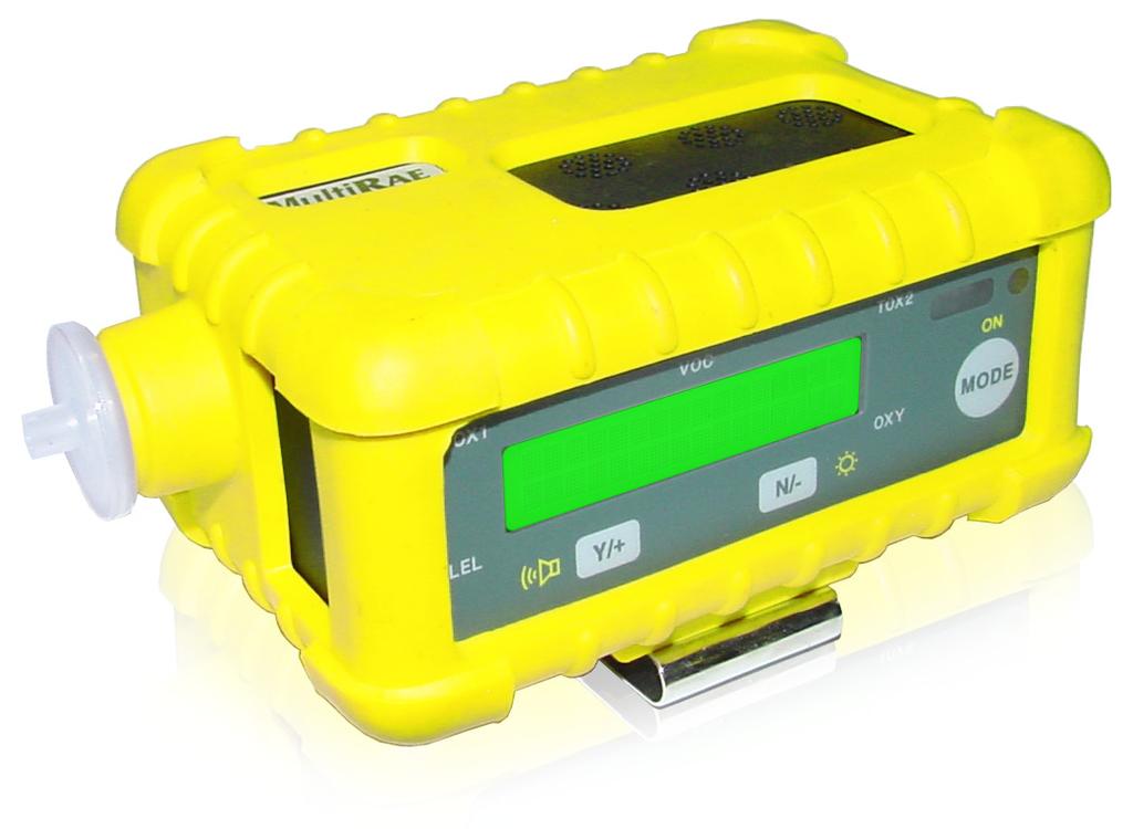
9 General Information The MultiRAE Plus is a programmable multiple-gas monitor designed to provide continuous exposure monitoring of toxic organic and inorganic gases, oxygen and combustible gases for workers in hazardous environments. The MultiRAE Plus is an extremely flexible one-to-five sensor instrument for use in confined space, emergency response, industrial hygiene, and many other monitoring applications. The MultiRAE Plus is the only instrument available on the market today that can offer protection using both standard gas detection sensors for the detection of oxygen, combutible gas, and specific toxic gases, as well as an integrated Photo- Ionization Detector (PID) for the ultimate broad-range toxic gas detection. The MultiRAE Plus is easily reconfigured and upgraded to meet your changing needs. Its versatility replaces a wide range of monitors, saving training, and maintenance costs. The MultiRAE Plus transitions quickly and easily from a sophisticated technician instrument to a simple text or display only monitor. The same monitor can be used as a personal monitor, a hand-held sniffer, or as a continuous operational area monitor. Dataloging-Enabled Monitors Datalog monitors are capable of storing datalog data in the instrument s non-volatile memory. When the version number appears during the power-on sequence, the D indicates a Datalog monitor. Call the factory to learn how to upgrade the instrument to a Datalog monitor. Physical Description 1. Display 2. Operation/programming keys 3. Visual alarm/charge status 4. Light sensor 5. Power jack 6. RS-232 port 7. Wrist strap holder 8. Buzzer and gas outlet 9. Gas inlet 10. External filter General Information 1
10 Operating the MultiRAE Plus The external filter must always be used with the monitor. Turning the Monitor On and Off To turn on, press MODE M. The monitor will beep once and go through a 90-second warm-up sequence as follows: On English, PGM-50 Multi-Gas Monitor, Software Version RAE Systems, Inc. (customizable using ProRAE Suite software) Monitor Type, Serial Number Date, Time, Temperature Checking Sensor ID s (As the MultiRAE Plus checks each sensor, it displays the date it was last calibrated and its warranty expiration date. If a new sensor is installed, it will ask for it to be calibrated.) Alarm Limits (for High, Low, STEL, TWA) Instrument Calibration (The last calibration date must be within the last 30 days for safe operation.) Battery Shut Off Voltage User Mode Alarm Mode Datalog Memory Datalog Time Left Datalog Mode Datalog Period MODE To turn off after the warm-up is complete, press and hold M for 5 seconds. The monitor beeps each second during the count-down sequence. Release when Off... flashes on the LCD. Plug the 110 VAC/12 VDC transformer into the monitor when not in use; the Charging.. message appears on the screen. User Modes The MultiRAE Plus has three user modes: Text, Display, and Advanced. Each mode provides a different level of access to the monitor s features. Text mode is the simplest mode, Advanced mode is the most complex. 2 Operating the MultiRAE Plus
11 The table shows the features in the order in which they appear. Regardless of which user mode the monitor is in, press MODE M to advance to the next available feature. Features Text Mode Display Mode Advanced Mode Sensor Names & Instantaneous Readings - instantaneous readings are the actual gas concentrations for the following sensors: TOX1 (toxic gas) parts-per-million (ppm) TOX2 (toxic gas) ppm VOC (volatile organic compound) ppm LEL (lower explosive limit) percentage OXY (oxygen) - percentage yes (with OK on LCD) yes yes PEAK - the highest reading for each gas concentration since the monitor was turned on; updated every second. MIN - the lowest reading for each gas concentration since the monitor was turned on; updated every second. STEL - the Short Term Exposure Limit for VOC and toxic gases only; the average reading of the gas concentration for the last 15 minutes, which is updated every minute. NOTE: **** will appear for the first fifteen minutes. TWA - the Time Weighted Average for VOC and toxic gases only; the accumulated reading of the gas concentration, divided by 8 hours, since the monitor was turned on. Updated every minute. no yes yes no yes yes no yes yes no yes yes Operating the MultiRAE Plus 3
12 Battery Voltage - the current battery voltage, measured in volts. Shut off - A fully charged battery will be 4.8 V or greater. When the battery voltage falls below 4.4 V, the Bat warning message appears and only minutes of run time remain before the instrument will automatically shut down (at 4.2 V). Date & Time, Run-Time and Temp - the runtime is how long the instrument has been on in hours and minutes. Start/Stop Datalog - turns manual datalogging on/off. LEL Gas - monitor measures LEL in units of specified target gas. NOTE: Correction factor may only be changed in Program Mode. VOC Gas - monitor measures VOC in units of specified target gas. NOTE: Correction factor may only be changed in Program Mode. Print Reading - capable of printing out the gas concentration readings if a serial printer is connected to the instrument. NOTE: This feature can be turn on using ProRAE Suite. PC Communication - capable of uploading data from the monitor to a computer or downloading configuration information from a computer to the monitor via a serial port. yes yes yes no no yes no no yes no no yes no no yes no yes yes yes yes yes 4 Operating the MultiRAE Plus
13 Calibrating the Monitor While all instruments are calibrated prior to leaving the factory, temperature extremes and/or shocks during shipment can cause sensor drift. Therefore, the accuracy of any newly purchased RAE Systems monitor should be tested by exposing the sensor(s) to known concentration calibration gas before the monitor is used or put into service. For maximum safety, the accuracy of the monitor should be checked by exposing the sensor(s) to known concentration calibration gas before each day s use. When should you calibrate the monitor? The monitor should be calibrated no less than every 30 days, or if it does not pass a fresh air reading, or if it does not pass a field verification. Calibration The sensors are calibrated in a two-step process using fresh air and span gas (a span gas contains a known concentration of a given gas). Some sensors may show sensitivity to other gases - this is called cross sensitivity. Therefore, it is important to choose the gas mixture carefully. We recommend the standard RAE Systems MultiRAE Plus 4-gas calibration mix (50% LEL methane, 20.9% oxygen, 25 ppm H 2 S, 50 ppm CO in a single gas cylinder) to calibrate the LEL, H 2 S and CO sensors, and isobutylene (100 ppm) for the PID. You will also need a calibration adapter in order to connect the monitor (with external filter) to the outlet of the gas cylinder. For the calibration of other toxic sensors, you will need the specific gas for that sensor. Getting Started To calibrate the monitor, the instrument must be in Program Mode. To enter Program Mode, press and hold MODE M and [N/-] for 5 seconds. If the monitor is in Text or Display Mode, you will be prompted for a password. Use [Y/+] to change the number. Use MODE M to move on to the next digit. The default password is Press and hold MODE M to submit the password. TOX1 VOC TOX2 Enter Password = 0000 LEL OXY Operating the MultiRAE Plus 5

14 TOX1 VOC TOX2 Calibrate Monitor? LEL TOX1 VOC TOX2 Fresh Air Calibration? LEL OXY OXY Span Gas Calibration Fresh Air Calibration The first step of calibration is a Fresh Air Calibration: Calibrate Monitor? Press [Y/+]. Fresh Air Calibration? Press [Y/+]. The monitor will cycle through each sensor. When the process is complete, the display will read, Zero Cal Complete. Zero Organic Filters for Zeroing PID Use an optional external zero organic filter (P/ N , 3-pack) when the ambient air may be contaminated with hydrocarbons. Attach the filter to the MultiRAE Plus during fresh air calibration. The filter can be used up to 20 times before disposing. This filter removes most heavier organic and inorganic compounds, but may not completely remove lighter compounds such as methane, propane, and CO. To complete step two of calibration, a Span Gas Calibration must be performed for each sensor. The instructions below are for a standard confined space entry instrument utilizing CO, H 2 S, LEL, Oxygen sensors. For this calibration you will need the standard RAE Systems MultiRAE Plus 4-gas calibration mix (50% LEL methane, 20.9% oxygen, 25 ppm H 2 S, 50 ppm CO in a single gas cylinder). For the calibration of other toxic sensors, or to calibrate a single sensor, please go to the Program Mode section of this manual. 6 Operating the MultiRAE Plus
15 Multiple Sensor Calibration Press [Y/+]. The monitor will assume you want to calibrate the CO, H 2 S, LEL and Oxygen sensors. Press [Y/+]. Apply the RAE Systems 4-gas span gas mixture and start the gas flow. TOX1 VOC TOX2 Multiple Sensor Calibration? LEL OXY TOX1 VOC TOX2 CO --- H 2 S LEL OXY LEL OXY The 60-second countdown timer appears. Span Cal Done Turn Off Gas message appears. The readings should be very close to the span gas values shown on the gas cylinder. TOX1 VOC TOX2 Span Cal done Turn off Gas Turn off the gas flow and disconnect the calibration adapter from the monitor. If calibration fails, an error message appears instead. Refer to Troubleshooting: Calibration Error Message on page 38. NOTE: If calibration is accidentally started and gas has run out or has been disconnected, press MODE M repeatedly. Calibration will stop and revert back to the previous calibration values. Calibrating the PID Sensor The single sensor method used to calibrate the PID can also be used to calibrate single toxic sensors. For the PID, use isobutylene (100ppm) span gas. For other toxic sensors, use the appropriate gas, e.g., ammonia sensor - use ammonia gas, etc. LEL OXY Operating the MultiRAE Plus 7
16 Single Sensor Calibration TOX1 VOC TOX2 Single Sensor Calibration? LEL OXY TOX1 VOC TOX2 CO OC H 2 S LEL pick OXY LEL OXY Press [Y/+]. When the installed sensors appear on the display use MODE M to move from sensor to sensor. Press [Y/+] to select the highlighted sensor and start calibration. Apply span gas mixture and start gas flow. The 60-second countdown timer appears. TOX1 VOC TOX2 Span Cal done Turn off Gas LEL NOTE: Some sensors (Cl 2, PH 3, NH 3, HCN) require a special presoak period prior to starting calibration. Turn the gas on to the MultiRAE Plus for this time period. Refer to Range, Resolution and Response Time chart on page 41 BEFORE starting the calibration procedure. When calibration has started and if the MultiRAE Plus displays No gas flow... apply gas or hit any key to start. Press [Y/+] to start calibration. OXY Calibration Time Stamp Y/+ Calibration is complete when the sensor name and its span value appear, confirmed by a Span Cal Done Turn Off Gas message. If no gas has reached a sensor after sixty seconds, calibration will abort. The readings should be relatively close to the span gas values. Turn off the gas flow and disconnect the calibration adapter from the monitor. If calibration fails, an error message appears instead. Refer to Troubleshooting: Calibration Error Message on page 38. A time stamp is created and stored each time a sensor calibration is performed, which is included in the datalog report. Press MODE M twice to exit calibration mode and return to the main display. NOTE: Residual gas may linger on the sensors for up to 60 seconds. If the sensors do not return to zero, repeat fresh air calibration. 8 Operating the MultiRAE Plus
17 MultiRAE Plus Usage Overview Storage Always keep the MultiRAE Plus on charge in a dry indoor area when not in use. If the MultiRAE Plus is to be stored more than 2 weeks off the charger, it is recommended to remove the Li-ion battery. Upon reinstalling the battery, it will need a complete charge and some sensors (like NO and NH 3 ) may require time to warm up, anywhere from 20 minutes to 24 hours. Refer to Technical Note-114 Sensor Specifications and Cross Sensitivities. The clock will also need to be reset. Confined Space Pre-Entry Test Test the atmosphere in the confined space by sampling air at 3 levels (Top, Middle and Bottom) in the Confined Space. Give the instrument time to sample the gas at each level - the correct sampling time is 60 seconds plus 1 second per every foot of hose. Alarms If there are any gas ALARMS at any level in the confined space it is not safe. DO NOT ENTER Identify the alarm condition and then start your preventive actions according to your company s Confined Space Entry procedures. No Alarms If there are no alarms, the Confined Space may be safe for entry. Disconnect the hose before carrying the MultiRAE Plus into the Confined Space. If monitoring is to be done by a Confined Space attendant, they should continue to monitor while you enter the area. If the unit alarms and BAT is displayed, the battery needs to be charged. There is 15 minutes or less of run time remaining. Leave the Confined Space immediately See the Applications and Technical Notes Guide for more information regarding Confined Space Entry and other applications. After Usage Turn the MultiRAE Plus off by pressing and holding MODE M. The buzzer will beep and count down and read OFF. Return the MultiRAE Plus to the dry, indoor storage area and connect the charger to the MultiRAE Plus. Operating the MultiRAE Plus 9
18 Alarm Signals When an alarm condition occurs, the monitor will provide audible and visual alarms to alert users of unsafe conditions. Refer to the Alarm Signals table on page 11 for a complete list of alarm conditions. The alarm signals are disabled while in the following modes: Communicate with PC, Print Reading, Calibrate Monitor. To reduce the risk of exposure to hazardous atmospheres, use these modes only in an area known to be non-hazardous. The alarm system can be set up in one of two ways: Auto Reset Alarm (default): The alarm signals automatically reset when the alarm condition is no longer present. NOTE: Not all alarm conditions have this option. Latched Alarm: The alarm signal remains on even when the alarm condition is no longer present; press [Y/+] to acknowledge and reset alarm signals. Testing Alarm Signals Press [Y/+]. If functional, the buzzer will beep once and the backlight will flash once. 10 Operating the MultiRAE Plus
19 Alarm Signal Alarm Condition beep/sec flash/sec vibration* Screen Message Reset Alarm Gas concentration exceeds High Alarm Gas concentration exceeds Low Alarm Gas concentration exceeds STEL Gas concentration exceeds TWA Gas concentration exceeds sensor range Unit short circuits or Reading over max range Excessive sensor negative drift Blocked inlet or Pump failure 3 3 yes sensor name HIGH 2 2 yes sensor name LOW 1 1 yes sensor name STEL 1 1 yes sensor name TWA 3 3 yes sensor name OVR 3 3 yes sensor name MAX 1 1 yes sensor name NEG move away from gas move away from gas move away from gas & wait 15 minutes move away from gas & turn unit OFF/ON move away from gas indicates possible sensor failure. calibrate sensor to verify performance perform zero calibration 3 3 yes PUMP unblock inlet; press to restart pump PID lamp fails to light 3 3 yes LAMP turn off/on or wait; lamp may turn on by itself Excessive LEL gas or LEL sensor is OFF 3 3 yes sensor name OFF move away from gas & turn LEL sensor ON (press Y/+ ) Low battery 1/min 1/min no Bat charge battery Datalog memory full 1 1 yes Mem clear datalog memory or turn on wrap-around Datalog memory write error 1 1 yes EEm turn unit OFF/ON Y/+ *The external vibration alarm is an optional feature. Operating the MultiRAE Plus 11
20 Preset Alarm Limits and Calibration The monitor is factory calibrated with standard calibration gas and is programmed with default alarm limits as listed: Gas Cal Gas/Balance Unit TWA STEL Low High CO 50/Air ppm H 2 S 25/N 2 ppm SO 2 5/N 2 ppm NO 25/N 2 ppm NO 2 5/Air ppm Cl 2 10/N 2 ppm O /N 2 %Vol CH 4 50/Air %LEL HCN 10/N 2 ppm NH 3 50/N 2 ppm PH 3 5/N 2 ppm VOC* 100/Air ppm *Note: 100 ppm isobutylene gas is used for VOC gas calibration Back Light The backlight assists reading the LCD in poor lighting conditions and automatically turns on anytime the MultiRAE Plus is in alarm. To manually turn on, press [N/-], and it will automatically turn off after 60 seconds. The backlight can also be set to automatically turn on in low lighting conditions, and likewise turn off in adequate lighting conditions. NOTE: The backlight can shorten the operating time by 20-30%. Sampling Pump The integrated sampling pump automatically turns on when the monitor is turned on and remains on during normal operation. The pump speed is adjustable between the default low setting (~200 cc/min) and the high setting (~300 cc/min). Use the low setting to save battery and filter life. Use the high setting for reactive gases and remote sampling in applications like Wingtank entry and HazMat. 12 Operating the MultiRAE Plus
21 The monitor can detect any obstructions in the external filter that causes a pump stall. The alarm will activate and a Pump error message will appear. To acknowledge the pump stall, press [Y/+] to start the pump again. Refer to Pump Stall on page 29 for details on how to adjust the pump stall threshold for either the high or low settings. Datalogging A small L at the center of the screen means the monitor is datalogging. Datalogging-enabled monitors can calculate and store hours of gas readings based on the time-interval and type of gas measurement specified. The time-interval can be set to between 1 and 3600 seconds in 1-second increments. The average and peak gas concentrations are the two types of gas measurements that can be stored for each sensor. NOTE: STEL and TWA values will only be logged if average is selected. All data is stored in non-volatile memory that can be downloaded to a computer. Users may select one of two types of memory storage: wraparound or stop. Refer to Select Memory Full Type on page 23. NOTE: Datalogging pauses upon entering Program Mode or PC Communication Standby Mode. Upon exiting Program Mode datalogging will resume. Upon exiting PC Communication Standby Mode, datalogging will resume only if datalogging mode was set to Automatic. Maximum Datalog Time for 5 Sensors Log Interval 1 sec 60 sec 300 sec (5 min) Tmax 80 minutes 80 hours 400 hours Datalog Options Automatic: Datalogging automatically starts/stops when the monitor is turned on/off. Manual: If the MultiRAE Plus is in Advanced mode, press [Y/+] at the Start Datalog screen. Set a timer to specify the maximum datalogging time using ProRAE Suite software. Periodic: Set a daily start/stop time to datalog using ProRAE Suite. Scheduled: Set a monthly start/stop time to datalog using ProRAE Suite. Operating the MultiRAE Plus 13
22 Charging the Battery Pack To charge the battery pack plug the transformer supplied with the monitor into the power jack on the monitor. When a Li-Ion battery pack is installed, charging automatically begins. The LED appears red during charging, and once the battery is fully charged, the LED turns green. The display also indicates the charge status. A completely drained battery pack charges to full capacity in less than 10 hours. When the Bat message appears on the LCD, the battery pack needs to be recharged. NOTE: A fully charged battery pack will switch to trickle charge to maintain battery life. Repeatedly turning the power to the transformer on and off will reset the charge and possibly burn out the battery. To change the battery pack or to use the alkaline battery adapter, refer to Replacing the Battery Pack or Emergency Alkaline Battery Adapter on page 32. If the MultiRAE Plus is to be stored more than 2 weeks off the charger, it is recommended to remove the Li-ion battery. 14 Operating the MultiRAE Plus

23 Accessories External Filters The external filter is a PTFE (Teflon ) membrane with a 0.2 micron pore that reduces the amount of liquid and dust that can contaminate the sensor. Using the external filter prolongs sensor and pump life. Change the external filter whenever it becomes discolored, clogged with particles, or draws in liquid. NOTE: Do not use the external filter when calibrating reactive gases. Instead, use the High Pump Speed setting and a short Teflon tube. Although this shortens battery life, it provides a faster response. Remote Sampling Probe When searching in hard-to-reach areas, use the standard remote sampling probe (P/N ) with a telescoping handle and 6 feet of Teflon tubing. For longer distances, attach a length of Teflon tubing. The monitor is capable of drawing samples from over 100 feet. Optional Dilution Fitting When gas samples have less than 10% oxygen, the dilution fitting (P/N /3026) will increase the oxygen concentration. The dilution fitting can also measure combustible, VOC or toxic gases when the concentration exceeds the upper limit of the sensor range. In Program Mode, set the dilution ratio to obtain the correct gas reading when the dilution fitting is used. The dilution fitting attaches directly to the meter and the sample tubing attaches to the dilution fitting. Refer to Technical Note-167 Proper Use of Dilution Fittings on Pumped Monitors for more information. The monitor and the dilution air inlet must be located in a clean atmosphere outside the confined space. Use either a remote sampling probe or Tygon tube test gas samples. Accessories 15
 and the other end to the calibration gas.")
24 Calibration Adapter The calibration adapter is a 6-inch Tygon tube with a male Luer connector on the end. During calibration, connect one end of the tube to the external filter (on the monitor) and the other end to the calibration gas. Alternatively, the calibration gas can be sampled from: an optional Tedlar gas bag (P/N ) filled with calibration gas, 16 Accessories

 directly from the gas cylinder.")
25 an optional open cup (P/N ) with calibration gas flow exceeding the pump demand, or an optional demand flow regulator (P/N , female or P/N , male) directly from the gas cylinder. Accessories 17
* 2.")


26 Using the Intrinsically Safe Barrier Box This does NOT ship with UL/cUL-approved monitors. The barrier box is only for ATEX European approved MultiRAE monitors. To conform to ATEX European safety standard, the barrier box must be used when utilizing an RS-232 cable and/or transformer. 1. RS-232 cable (detachable)* 2. Computer interface cable 3. Transformer (detachable)** 4. Intrinsically safe barrier 5. Power cable 6. MultiRAE Plus monitor 1* 2 3** Communicating with a Computer * This connection is not necessary during normal charging. Connect the RS-232 cable from the barrier box to the monitor. Connect the computer interface cable to the barrier box. Plug the computer interface cable into a computer. Charging the Monitor ** Connection is optional during computer communication. Connect the power cable from the barrier box to the monitor. Connect the transformer to the barrier box. Plug the transformer into an appropriate outlet. 18 Accessories
27 Programming Mode In addition to calibration, authorized users may change the monitor settings to their requirements using the Programming Mode. NOTE: Monitoring gas concentrations continues during Programming Mode, but pauses during Calibration. Datalogging also pauses during Programming Mode, but resumes when programming is finished. Press Press Press Y/+ MODE for desired menu to answer no to decrease a digit for desired submenu to answer yes to increase a digit to return to the sensor name/ instantaneous reading display to exit a submenu to advance digits N/- To enter the Program Mode, press MODE M and [N/-] together until the first program menu appears: Calibrate Monitor? Refer to Getting Started on page 5. The figure on the following page summarizes the programming menus and how to navigate through them. Program Mode 19
28 Programming Menus Sensor Name / Instantaneous Readings MODE Calibrate Monitor? Y/+ Fresh Air Calibration? Multiple Sensor Calibration? Single Sensor Calibration? Modify Span Gas Value? Change LEL / VOC Span Gas? MODE Y/+ or N/- MODE Change Alarm Limits? Y/+ Change High Alarm Limit? Change Low Alarm Limit? Change STEL Alarm Limit? Change Average Alarm Limit? MODE Y/+ or N/- MODE Change Datalog? Y/+ Clear All Data? Change Datalog Period? Select Data Type? Enable / Disable Datalog? Select Memory Full Type? MODE Y/+ or N/- MODE Change Monitor Setup? Y/+ Change Site ID? Change ID Mode? Change User ID? Change Alarm Mode? Change User Mode? Change Real Time Clock? Change Backlight Mode? Change Password? Change Pump Speed? Change Averaging Method? Change Display Language? Set Temperature Unit? MODE Y/+ or N/- MODE Change Sensor Configuration? Y/+ MODE & N/- N/- N/- N/- N/- N/- Change LEL / VOC Gas Selection? Enable / Disable Sensor? Change Dilution Ratio? Change PID Lamp Type? Y/+ or N/- MODE 20 Program Mode
29 Security Levels Security levels are setup via computer using ProRAE Suite. The default password is: NOTE: For security purposes 0000 always appears instead of actual password. No changes will be saved unless the user is in the correct mode with the correct security level. User Mode Text Display Advanced Security Level Calibrate Monitor? Fresh Air Calibration? * * * * * * * Multiple Sensor Calibration? * * * * * * * Single Sensor Calibration? * * * * * * * Modify Span Gas Value? * # * * * # * * # * Change LEL/VOC Span Gas? * # * * * # * * # * Change Alarm? Change High Alarm Limit? * # * * * # * * # * Change Low Alarm Limit? * # * * * # * * # * Change STEL Alarm Limit? * # * * * # * * # * Change Average Alarm Limit? * # * * * # * * # * Change Datalog? Clear All Data? * * * * * * * Change Datalog Period? * # * * * # * * # * Select Data Type? * # * * * # * * # * Enable/Disable Datalog? * * * * * * * Select Memory Full Type? * * * * * * * Change Monitor Setup? Change Site ID? * * * * * * * Change ID Mode? * * * * * * * Change User ID? * * * * * * * Change Alarm Mode? * # * * * # * * # * Change Alarm Mode? * # * * * # * * # * Change User Mode? * # * * * # * * # * Change Real Time Clock? * # * * * # * * # * Change Backlight Mode? * * * * * * * Change Password? * # * * * # * * # * Change Pump Speed? * # * * * # * * # * Change Averaging Method? * # * * * # * * # * Change Display Language? * # * * * # * * # * Set Temperature Unit? * # * * * # * * # * Change Sensor Configuration? Change LEL/VOC Gas Selection? * # * * * # * * # * Enable/Disable Sensor? * * * * * * * Change Dilution Ratio? * # * * * # * * # * Change PID Lamp Type? * # * * * # * * # * * Need password # No change allowed Program Mode 21
30 Calibrate Monitor Fresh Air Calibration? Refer to Calibrating the Monitor on page 5. Multiple Sensor Calibration? Refer to Calibrating the Monitor. Single Sensor Calibration? Refer to Calibrating the Monitor. NOTE: After a single sensor oxygen calibration, perform fresh air calibration to ensure the oxygen sensor is calibrated correctly. Modify Span Gas Value? The span gas is the second point of reference for calibration. Users may modify the span values of the standard calibration gases to use other calibration gases. However, DO NOT modify the span values when using the RAE Systems calibration gas supplied with the monitor. Change LEL/VOC Span Gas? Change the type of calibration gas from methane (LEL) and isobutylene (VOC) to be used as the span gas during LEL or VOC gas calibration. However, DO NOT modify the span gases when using the RAE Systems calibration gas supplied with the monitor. Change Alarm Limits MODE To escape the submenu without saving changes, press M. To save, press MODE M until Save? appears. Press [Y/+] to save changes, otherwise press [N/-] to discard changes. Oxygen Sensor Calibration: The oxygen sensor calibration is slightly different from other sensors; span calibration at 20.9% O 2 is perormed during fresh air calibration. During single sensor calibration, the oxygen sensor can be calibrated to 0% O 2 with pure nitrogen gas, by pressing [Y/+] when asked 0%? Oxygen? To calibrate at a different concentration specified in Modify Span Gas Value, press [N/-]. Users may change the alarm limits for each sensor. Use [N/-] to cycle through the submenu options. Press [Y/+] to enter a submenu. To MODE modify the limit, use [Y/+] and [N/-] to change the value. Use M to move from character to charater. N/- Change High Alarm Limit? Change Low Alarm Limit? Change STEL Alarm Limit? (Short Term Exposure Limit) Change Average Alarm Limit? (TWA Time Weighted Average) 22 Program Mode
31 Change Datalog Setting The monitor calculates and stores the gas readings at specified intervals, which can be reviewed by the user. Users may also program additional datalog options for the monitor through the computer. Clear All Data? Erase all data stored in the non-volatile memory, but does not delete the PEAK, MIN, STEL, TWA displayed values, which are stored separately. Change Datalog Period? Program the datalog period from 1 second to an hour (3,600 seconds). Select Data Type? Store either the average (TWA) or peak value for each datalog interval. If peak values are selected, average values like STEL and TWA will not be selected. Enable/Disable Datalog? Enable or disable the datalogging function for each sensor. If a * is displayed next to a sensor name, data will be recorded. Use MODE M to move from sensor to sensor. An asterisk (*) means the sensor is enabled; no asterisk means the sensor is disabled. Press [Y/+] to select or press [N/-] to deselect. To save changes, press MODE M until Save? appears. Then press [Y/+] to accept. Otherwise, hold MODE M to escape and cancel changes. Select Memory Full Type? The instrument s memory can store about 3 days worth of data, as a result of continuous monitoring at 1-minute intervals. Users may select one of two types of memory storage: Wrap-around: after the memory becomes full, the latest data overwrites the oldest data. e.g. the most recent 3 days worth of data is stored. Stop: halts datalogging when the memory is full, and the MEM alarm sounds. e.g. the first 3 days worth of data is stored. Program Mode 23
32 Change Monitor Setup Change Site ID? Enter an eight-character alphanumeric site identification, which is included in datalog reports. Change ID Mode? Set up an identification code to use during start-up or to access a previously saved customized ID. Change User ID? Enter an eight-character alphanumeric user identification, which is included in datalog reports. Change Alarm Mode? Choose either latched or automatic reset. The user must manually acknowledge a latched alarm by pressing [Y/+]. Change User Mode? The three different user modes are: Text, Display and Advanced. Change Real Time Clock? Change or update the real time clock and calendar. Change Back Light Mode? Change the monitor setup or enter user information for the monitor. Use MODE M to move the cursor from character to character. Use [Y/+] and [N/-] to toggle up and down the alphabet and numbers. To save, press MODE M until Save? appears. Press [Y/+] to save changes, otherwise, press [N/-] to discard changes. To escape this menu without saving changes, press and hold MODE M. Automatic the monitor turns the back light on/off when ambient light falls below/above the threshold or Manual press [N/-] to turn the back light on/off. Change Password? Modify the password. 24 Program Mode
33 Change Pump Speed? Low (default) use when operating conditions are slow to change; prolongs pump motor life, LEL sensor life and battery run time. High use for long lengths of tubing or when rapid changes in input conditions are expected, such as HazMat response or when used for measuring heavy, low vapor pressure compounds like jet fuel. Change Averaging Method? Choose: TWA (default) an eight-hour Time Weighted Average or AVG the running average Change Display Language? Choose English or Spanish. Set Temperature Unit? Choose Celsius or Fahrenheit to measure temperature. Change Sensor Configuration Change LEL/VOC Gas Selection? Choose an LEL or VOC gas listed in the monitor to calculate its correction factor relative to the LEL or VOC calibration gas. Refer to Correction Factors on page 26. The correction factor allows the unit to display the equivalent concentration of the selected LEL or VOC gas. To create a custom factor for a specific gas or mixture of gases, modify the relative correction factor to increase or decrease the gas reading. Enable/Disable Sensor? Enable or disable sensor(s); a disabled sensor will not measure or display the gas concentration. Use if a sensor has failed or is providing erroneous readings. Use MODE M to move from sensor to sensor. An asterisk (*) means the sensor is enabled; likewise, no (*) means the sensor is disabled. Press [Y/+] to select or press [N/-] to deselect. To save changes, press MODE M until Save? appears. Then press [Y/+] to accept. Otherwise, hold MODE M to escape and cancel changes. Program Mode 25
34 Change Dilution Ratio? Attach an optional dilution fitting on the gas inlet port to dilute the gas sample. Enter a dilution ratio (from 1 to 10) to compensate the reading for the actual gas concentration. Change PID Lamp Type? This only applies to PID monitors. The PID sensor can utilize either a 10.6 ev or an 11.7eV UV. Since each lamp type has a different correction factor table, it is important to select the correct lamp type. Correction Factors VOC and LEL sensors respond to a broad range of gases and show a different sensitivity to different gases; correction factors allow measurement of a specific gas (the measurement gas) while using a different gas for calibration (the calibration gas). The correction factor (CF) for a measurement gas is defined as: CF = Sensitivity to a Calibration Gas Sensitivity to a Measurement Gas To convert the monitor reading of the calibration gas to the true concentration of a measurement gas, use the following equation: True Concentration (ppm) = CF x Monitor Reading (ppm) The monitor has three sets of correction factors, one for the LEL and two for the VOC (10.6 ev and 11.7 ev) Each set consists of 20 to 40 different gases. Specify the PID lamp type (e.g ev or 11.7 ev) to access the proper VOC correction factor. To set up a correction factor, first choose a calibration gas in the Calibrate Monitor program menu and then choose a measurement gas in the Change Sensor Configuration menu. If the calibration gas is different from methane for LEL or isobutylene for PID, then the new CF is calculated and the displayed value will be different from the values in Technical Notes 106 or 156. NOTE: Correction factors provide an estimate of the measurement gas concentration. For greatest accuracy, it is necessary to calibrate the LEL or VOC sensor directly with the measurement gas. Refer to Technical Note-106 Correction Factors and/or Technical Note- 156 LEL Correction Factors. 26 Program Mode
35 Diagnostic Mode The monitor is equipped with a diagnostic mode that can display critical, low lever parameters to help users identify problems. Refer to Troubleshooting on page 38. The diagnostic mode allows the user to set several low level parameters which are very critical to the operation of the monitor. Extra care should be taken when setting these low level parameters. If the user is unfamiliar with these parameters and sets them incorrectly, it may cause the monitor to shut down or malfunction. The diagnostic mode should only be used by qualified personnel. To switch the monitor to diagnostic mode, turn the monitor off. Press and hold [Y/+] and MODE M together; release both keys when the unit beeps. The monitor is now in diagnostic mode. Press MODE M until the desired diagnostic parameter appears: Sensor Name and Raw Sensor Readings If a sensor is programmed and is properly installed, the sensor name should appear. If the sensor name does not appear, then the sensor may be improperly programmed or defective. The raw sensor reading is the uncalibrated output for each sensor. When fresh air is applied, the raw sensor readings should be 200 to 700 for toxic gas and VOC sensors; 100 to 1300 for the LEL sensor; and 1200 to 2300 for the oxygen sensor. When calibration gas is applied, the raw sensor readings should increase or decrease by the amounts listed in Technical Note Special Diagnostic Modes. If the raw sensor readings are outside the normal range or do not change when gas is applied, the sensor or monitor may be defective. RF Test (Radio Frequency) This feature applies when the monitor is used with the RAELink Remote package. The RF test shows the successful rate of communication. Adjust Lamp Failure Threshold If the lamp physically appears fine, but the Lamp error message appears during normal operation, the lamp failure threshold may be set too high. Diagnostic Mode 27
36 To adjust the level: Turn the monitor on in diagnostic mode and go to the Lamp = xxx, Fail = yyy +/- display. ( xxx is the lamp current reading; yyy is the value of the lamp failure threshold.) Decrease the yyy value until it is about 10 counts below the xxx value. Press MODE M to exit. Then press [Y/+] to save changes, or press [N/-] to discard changes. Battery Type and Bias The type of battery (Lithium-Ion battery pack or alkaline battery adapter) used to charge the monitor is displayed. Some toxic gas sensors require a bias voltage of a few hundred millivolts for the sensor to function properly. These include NO and NH 3 sensors. To manually switch the bias voltage supply on, refer to Special Bias Voltage for Toxic Sensors on page 35. Install a biased sensor in the TOX1 socket. If the bias voltage is switched on, the bias reading should be below 182, otherwise it may be defective. Show x1 and x10 Range of PID Sensor (PID detectors only) The PID sensor is connected to two amplifiers with two different gains: unity gain and gain of ten; these are the raw outputs of both amplifiers. When fresh air is applied, both amplifier outputs should be 200 to 500. When a VOC gas is applied, both amplifier outputs should increase; the amount of increase for the unity gain (x1) should be 1/10 of the increase for the gain of ten (x10). If the increase does not agree with the expected value, then the gain switch of the amplifier may be defective. Display Contrast LEL Power Y/+ The top line indicates the instantaneous reading of raw counts from the LEL sensor. The bottom line shows if the LEL sensor is on or off. Press [N/-] to turn the power off, and press [Y/+] to turn the power on. Press [Y/+] to increase the contrast and [N/-] to decrease the contrast. The LCD contrast bar indicates the current setting. If the display appears to have dark lines, press [Y/+] a few times to see the display more clearly. NOTE: In extreme temperatures, the display may fade or bleed out. N/- 28 Diagnostic Mode
37 Clock, Time, Battery, and Temperature This display shows the real time clock, the date, the battery voltage in raw count and temperature sensor reading. Sensor Expiration Date The expiration date (month and year) for each installed sensor is based on the manufacturing date and expected life of each sensor. If the current date exceeds the expiration date for any sensor, the performance of the given sensor cannot be guaranteed. It is strongly recommended to replace the sensor immediately to ensure proper operation. Pump Stall The Pump = 20/20 reading is the minimum and maximum pump raw count (RC), and Stall = 40 +/- is the pump stall threshold. The pump stalls if the maximum raw count reaches the pump stall threshold, which causes the pump to shut off. To determine the pump stall threshold: [ (max RC when pump is free + max RC when pump is blocked) ] 2 Back Light Threshold Adjust the threshold for the LCD backlight to automatically turn on/off; verify the threshold is 100, which is suitable for most situations. Serial Number and Pump To adjust the pump stall threshold, press [Y/+] to increase or [N/-] to decrease the numerical value. Displays the monitor s serial number and the pump status. If a pump is installed and a pump speed control circuit is available, toggle the display Pump=Low/High by pressing [N/-]. NOTE: Changes made are only for testing the pump condition and are not saved to the nonvolatile memory. Refer to Change Pump Speed on page 25. Battery Duration Time Use to test battery life and displays the last run time before the unit turned itself off due to low battery. Communicate with PC Connect monitor to a personal computer to upload a configuration file or download stored data. Diagnostic Mode 29

38 Maintenance Power from the battery is flowing to the printed circuit board (PCB) and sensors even when the power is off. Therefore, it is very important to disconnect the battery pack before servicing or replacing sensors or any components insides the monitor. Severe damage to the PCB may occur if the battery pack is not disconnected before servicing the unit. monitor cover Li-Ion battery pack PID shielding cap toxic sensors LEL sensor oxygen sensor PID sensor lamp monitor case printed circuit board (PCB) 30 Maintenance


39 Li-Ion Battery Pack The factory supplied Li-Ion battery pack is designed to last for 10 hours of normal operation (without alarm or backlight conditions).the rechargeable batteries have a 1-year warranty. Age, ambient temperature, and heavy useage may impact battery life. Battery packs will slowly drain even if the monitor is turned off. If the battery packs have not been charged for 10 days, the battery voltage will be low. It is recommended to fully charge the battery packs before going into the field, and recharge the battery pack upon returning from the field. To reduce the risk of ignition of hazardous atmospheres, recharge battery only in areas known to be non-hazardous. Remove and replace battery only in areas known to be non-hazardous. Ne charger les batteries que dans emplacements désignés non dangereux. Replacing the Battery Pack To reduce the risk of ignition of hazardous atmospheres, recharge battery only in areas known to be non-hazardous. Remove and replace battery only in areas known to be non-hazardous. Ne charger les batteries que dans emplacements désignés non dangereux. Remove the monitor cover by loosening the two case screws, and then unplug the battery pack from the battery jack. Place a fully charged spare battery pack into the monitor. Make sure the battery plug is connected securely. Reattach the cover and tighten the screws. Maintenance 31


40 Emergency Alkaline Battery Adapter The alkaline battery adapter supplied by RAE Systems is intrinsically safe. The adapter is intended to be used in emergency situations when there is no time to recharge the Li-Ion battery pack. The adapter accepts 4-AA alkaline batteries to provide approximately hours of operation. To install the adapter, remove the monitor cover. Remove the Li-Ion battery pack from the monitor by carefully disconnecting the wires. Install four AA alkaline batteries into the battery adapter, making sure the battery polarity is correct. Connect the battery adapter to the monitor. Make sure the wires are placed inside the adapter, running between the batteries. Close the flap over. Install the battery adapter in the monitor. The monitor automatically detects the alkaline batteries and will run for 8-10 hours. Use the monitor once the alkaline battery adapter is installed. Replace the alkaline batteries when spent. 32 Maintenance

41 Sensor Replacement Under normal operating conditions, most sensors will lose their original sensitivity after the expected operating life and eventually need to be replaced. Each sensor has a non-volatile memory that has the manufacturing and expiration dates, which appear during the warm-up period or can be looked up in the diagnostic mode. Warranties: Oxygen (O 2 ), combustible gas (LEL), hydrogen sulfide (H 2 S) and carbon monoxide (CO) sensors all have a 2-year warranty. All other toxic sensors have a 1-year warranty. NOTE: The Oxygen and the LEL sensors have assigned sockets. These are identified on the PCB. High bias toxic sensors should be installed in socket 1/A. Refer to Special Bias Voltage for Toxic Sensors on page 35. Any toxic sensor can be installed in socket 2/B. Replace the sensor when it fails to calibrate. To replace sensor(s), turn the monitor off and remove the cover. Using the sensor puller, remove the sensor to be replaced by carefully pulling straight out. Plug a new sensor into the empty socket. Make sure the sensor pins are aligned with the socket holes before firmly pushing the sensor all the way down. Replace the monitor cover. Turn on the power of the monitor and the newly installed sensors should be recognized. Let the monitor run for 15 minutes before calibration. Some sensors, like NO and NH3, require up to 24 hours on-bias in the monitor prior to calibration and use. Refer to Techincal Note 114 Sensor Specifications and Cross Sensitivities. NOTE: Calibrate all sensors prior to use Maintenance 33

42 CO Sensor Charcoal Filters CO sensors can be sensitive to hydrocarbons. To reduce or eliminate this cross sensitivity, a charcoal filter is installed in the gas plate above the CO sensor. The charcoal filter removes organic vapor crosssensitivity and will last 4-6 weeks under normal operation conditions before it needs to be replaced. However, if the monitor is exposed to high concentrations of VOC gases, the carbon filter needs to be replaced more frequently. (P/N , 5-pack; keep unused filters sealed during storage.) Refer to Technical Note-121 CO Sensor Cross-Sensitivity and Removal with Charcoal Filter for cross-sensitivity data. The carbon filter used for CO sensors may lower the reading if used on other sensors. Remove the filter if another sensor is replacing a CO sensor in the monitor. place carbon filter above the CO sensor in either position, not both 34 Maintenance

43 Special Bias Voltage for Toxic Gas Sensors NO and some NH 3 sensors require a special high bias. The bias pins are located next to the PID sensor socket. Using the sensor puller, move the stopper block from the OFF pins to the ON pins. The sensor ID and bias voltage will be checked during the power on sequence. An error message appears if the sensors are plugged into the wrong socket, or if the bias voltage is disabled. Biased sensors require 24 hours on bias before calibration. stopper block in ON position three bias pins (display side) socket 1/A socket 2/B Maintenance 35

44 PID Sensor Cleaning/Replacement During the course of normal operation, a film of gas vapor may build up inside the PID sensor module and the lamp; the rate of build-up depends on the type and concentration being sampled. As a guide, it is recommended to clean the PID sensor module and lamp only when the PID is malfunctioning. Periodically cleaning the lamp window also removes film deposits and restores lamp sensitivity. Exercise with care when cleaning the window surface to avoid damage. Turn the monitor off and remove the cover. Remove the stainless steel shielding cap for the PID sensor. Using the sensor puller, remove the PID sensor by carefully pulling straight out. Dip the entire PID sensor into RAE Systems lamp cleaning solution (supplied in the Lamp Cleaning Kit, P/N ). DO NOT store the methanol from the lamp cleaning kit in the same case as the MultiRae Plus, as long-term exposure to methanol can damage electrochemical sensors. It is highly recommended to use an ultrasound bath for at least three minutes. Then thoroughly air-dry the sensor. DO NOT use heat to dry sensors. DO NOT disassemble PID sensor. If the lamp is operational, use a cotton swab or lens tissue to clean the flat window surface with GC grade methanol. If the lamp does not turn on replace with a new lamp. Avoid contact with the flat window surface. Reinstall the PID sensor. Install the shielding cap. Replace the monitor cover. Taking Care of the Lamp shielding cap P/N PID sensor P/N lamp 10.6 P/N P/N Never touch the window surface with fingers or anything which may leave a film. Water will degrade window surfaces, especially the 11.7 ev lamp window. 36 Maintenance

45 The 10.6 ev PID lamp has a 1-year warranty. The Lamp error is an indication of a problem with the lamp current. A dirty or contaminated sensor often causes high readings of the VOC sensor. A weak or inoperative lamp often causes low readings or no response to test gas. If the UV lamp is on while the error message persists, then it is necessary to adjust the lamp threshold. Refer to Adjust Lamp Failure Threshold on page 27. Sampling Pump Replacement The sampling pump is a positive displacement piston pump, which needs to be replaced as it approaches the end of its life span. The pump s draw capability reduces significantly as it consumes a greater amount of energy to keep running. The sampling pump has a 1-year warranty. To replace the pump: Turn the monitor OFF and remove the cover. The sampling pump is attached to the cover. Remove the single screw holding the pump to the cover. Gently pull the pump assembly off the cover. Replace with a new pump assembly and reassemble. pump cover Maintenance 37
46 Troubleshooting Technical Service: or Problem Possible Reason(s) Possible Solution(s) Cannot turn on after charging battery. Incorrect Year - Check Clock error message. Cannot turn off. Corrupted characters. No LED or LCD backlight. Defective battery. Microprocessor hangup. Battery has died and there is a mismatch between the date code on the sensors and its internal clock. Microprocessor hangup. Defective LED or LCD backlight. Charge or replace battery. Disconnect then reconnect battery to reset computer. Otherwise, install alkaline battery pack. If that still does not work, then call Service. Press [Y/+] and reset clock. Disconnect and reconnect battery to reset computer. Reload firmware. Check if backlight is in manual mode. Otherwise, call service center. Lost password. Forgot. Use ProRAE Suite to reset password. Buzzer inoperative. Calibration error message. Voltage too high error message, while charging. Bat error message. Bad buzzer. Setting could be in special run silent mode. No calibration gas input. Low sensitivity to calibration gas. Battery fuse blown. Wrong AC adapter. AC adapter not fully plugged in. Battery low. Call authorized service center. Check standard gas flow path or cylinder pressure. Change calibration gas or sensor. Check battery and adapter. Recharge battery. 38 Troubleshooting
47 High pump noise. No inlet suction. Abnormally low reading. Abnormally high reading. Reading jumping around. Read a small background value. Lamp error message. VOC reading plateaus at certain level. Full scale measurement in humid environment. Leaky inlet path. Defective pump. Bad calibration. Low sensitivity to calibration gas. Wrong span value. Bad sensor. Low flow. Bad calibration. Wrong span value. Dirty PID sensor. Dirty filters. Excessive moisture. Incorrect calibration gas. Wrong span value. Small background gas level present. Sensor zero drift or newly installed. Wrong threshold. Weak lamp. Dirty Sensor. Weak PID lamp. Dirty PID sensor. Dirty or wet sensor. Check inlet connection. Clean or replace pump. Recalibrate. Use stronger span gas. Check span value. Replace sensor. Replace filters. Check flow. Recalibrate. Check span value. Clean PID sensor in methanol in ultrasound bath. Replace filters. Dry PID sensor. Calibrate the sensors. Use different calibration gas. Change sensor. Run fresh air calibration. Wait for newly installed sensor to stabilize. Adjust threshold. Clean or replace lamp. Clean PID sensor. Replace lamp. Clean lamp & PID sensor. Replace filters. Clean and dry sensor. Replace external filter. Troubleshooting 39
48 Specifications Size Weight Sensors Battery Operating Hours Display Keypads Direct Readout Alarms Datalogging 4.65 L x 3.0 W x 1.9 H (11.8 x 7.6 x 4.8 cm) 16 oz with battery (454g) Up to 5 sensors including: Photo-Ionization detector for VOCs, 10.6 ev lamp standard Protected catalytic bead for combustible gases Interchangeable electrochemical sensors for oxygen and toxic gases (2) Interchangeable Li-Ion and alkaline battery packs Rechargeable units include lithium-ion battery pack with internal smart charging, 120V AC/DC wall adapter, and spare alkaline battery pack 14 hours continuous with Li-Ion (typical) Unit will run and charge simultaneously 2 line, 16 digit LCD with LED backlighting automatically in dim light or alarm condition 1 operation and 2 programming keys Instantaneous (up to 5) values: Oxygen as percentage by volume Combustible gas as percentage of lower explosive level (LEL) Toxic gases and VOCs as parts per million by volume (VOC scaleable using correction factors) High and low values for all gases STEL and TWA values of toxic gases and VOCs Battery and shut down voltage Date, time, elapsed time, temperature 90 db buzzer and flashing red LED to indicate exceeded preset limits: High: 3 beeps and flashes per second Low: 2 beeps and flashes per second STEL and TWA: 1 beep and flash per second Automatic reset or latching with manual override Additional diagnostic alarms and display messages for low battery and pump stall 20,000 points (80 hours, 5 channels at one minute intervals) download to PC with serial number of unit, user ID, site number, and calibration date 40 Specifications
49 Calibration Sampling Pump Low Flow Alarm Temperature Humidity Attachment Warranty EMI Immunity Two-point field calibration for zero and span gas Internal two-speed pump. Flow rates: Low: ~200 cc/min High: ~300 cc/min Auto shut-off pump at low flow condition -4 to 113 F (-20 to 45 C) 0% to 95% relative humidity (non-condensing) Wrist strap and high-visibility rubber boot Lifetime on non-consuming components (per RAE Standard Warranty). 2 years for O 2, LEL, CO, and H 2 S sensors. 1 year all other sensors. 1 year pump, 1 year battery, 1 year for 10.6eV PID lamp. No effect when exposed to 0.43 mw/cm RF interference (5 watts at 12 inches) Intrinsic Safety U.S.A. and Canada: UL & cul Class I, Division I, Groups A, B, C, D, hazardous locations, Temperature Code T3C Europe: DEMKO 03 ATEX X; EEx ia d IIC T4 (w/ Battery P/N ); EEx ia d IIC T3 (w/ Battery P/N ) Range, Resolution & Response Time (t 90 for pump-equipped instruments) Sensor Range Resolution t 90 (sec) Presoak Time for 60-sec Cal LEL 0-100% LEL 1% 15 None VOC ppm 0.1 ppm 10 None VOC ppm 1 ppm 10 None O % 0.1% 15 None CO ppm 1.0 ppm 40 None H 2 S ppm 1.0 ppm 35 None SO ppm 0.1 ppm 35 None NO ppm 1.0 ppm 30 None NO ppm 0.1 ppm 25 None Cl ppm 0.1 ppm sec PH ppm 0.1 ppm sec NH ppm 1.0 ppm sec HCN ppm 1.0 ppm sec Specifications 41
50 Service and Repair Record Date Service / Repair Type 42 Service and Repair Record
51 Notes

52 RAE Systems by Honeywell Main Office 3775 N. First Street San Jose, CA , USA Telephone Fax Instrument Sales Technical Service Website SPECIAL NOTE: If the monitor needs to be serviced, contact either: the RAE Systems distributor where the unit was purchased; they will return the monitor on the user s behalf, or the RAE Systems Technical Service department. Before returning the unit for service or repair, obtain a Returned Material Authorization (RMA) number for proper tracking of your equipment. This number needs to be on all documentation and posted on the outside of the box in which the monitor is returned for service or upgrade. Packages without RMA Numbers will be refused at the factory.
Using the QRAE Plus personal multigas monitor
 Using the QRAE Plus personal multigas monitor Firmware v 1.10 QRAE Plus The Hazardous Environment Detection Company QRAE Plus features Turning on the QRAE Plus Recommended Daily Start-up Procedure User
AreaRAE PGM-5020 WIRELESS MULTI-GAS MONITOR. Operation & Maintenance Manual Document Number: Revision B, April 2003
 AreaRAE PGM-5020 WIRELESS MULTI-GAS MONITOR Operation & Maintenance Manual Document Number: 029-4001-000 Revision B, April 2003 This product may be covered by one or more of the following U.S. Patents:
Operate the Mutli-Gas Monitor PID
 TASK: Operate the Multi-Gas Monitor Learning Objective CONDITION: In a classroom environment, given a fully charged Multi-gas Monitor with the manufacturer operator s manual, all monitor components/accessories,
RAE Systems Systems. User Presentation. October Protection Through Detection
 RAE Systems Systems AreaRAE Inert User Presentation October 2009 www.raesystems.com AGENDA Overview & Features Basic Operation Turning the AreaRAE Inert monitor ON Warnings NORMAL & INERT Mode Displays
UltraRAE 3000 User s Guide
 UltraRAE 3000 User s Guide Rev. A May 2008 P/N 059-4023-000 FCC Information Contains FCC ID: S22BTMODULE-CL2 The enclosed device complies with part 15 of the FCC rules. Operation is subject to the following
MiniRAE Lite User s Guide
 MiniRAE Lite User s Guide Rev. B March 2010 P/N 059-4022-001 Copyright 2009 RAE Systems, Inc. Contents 1 Standard Contents... 8 2 General Information... 8 3 Physical Description... 9 4 Specifications...
MiniRAE 3000 User s Guide
 MiniRAE 3000 User s Guide Rev. A April 2007 P/N 059-4020-000 Copyright 2007 RAE Systems, Inc. Contents Read Before Operating... 4 Special Notes... 5 Warnings... 6 Standard Contents... 8 General Information...
Using the MiniRAE 2000 & ppbrae PID
 MiniRAE 2000 Using the MiniRAE 2000 & ppbrae PID Firmware v. 1.20 (rev C) The Hazardous Environment Detection Company Training Agenda: MiniRAE 2000 & ppbrae features Turning on the MiniRAE 2000 & ppbrae
QRAE II User s Guide. Covers QRAE II Diffusion & Pump Models with Firmware Version 3.60 or higher
 QRAE II User s Guide Covers QRAE II Diffusion & Pump Models with Firmware Version 3.60 or higher P/N 020-4100-000 Rev. F May 2013 Copyright 2011 RAE Systems by Honeywell Contents Read Before Operating...
QRAE II User s Guide. Covers QRAE II Diffusion & Pump Models with Firmware Version 3.12 or higher
 Covers QRAE II Diffusion & Pump Models with Firmware Version 3.12 or higher P/N 020-4100-000 Rev. E April 2010 Copyright 2010 RAE Systems, Inc. Contents 1 General Information... 6 1.1 Key Features... 6
MiniRAE 3000 User s Guide
 MiniRAE 3000 User s Guide Rev. C August 2010 P/N 059-4020-000 FCC Information Contains FCC ID: PI4411B The enclosed device complies with part 15 of the FCC rules. Operation is subject to the following
AreaRAE. Wireless Multi-Gas Monitor. Includes AreaRAE, AreaRAE Gamma, AreaRAE Gamma Steel, And AreaRAE Steel
 AreaRAE Wireless Multi-Gas Monitor Includes AreaRAE, AreaRAE Gamma, AreaRAE Gamma Steel, And AreaRAE Steel Operation & Maintenance Manual Document Number: 029-4034-000 Revision A, September 2006 This product
ToxiRAE 3 User s Guide
 ToxiRAE 3 User s Guide P/N G01-4002-000 Rev. C May 2008 Copyright 2008 RAE Systems, Inc. Contents 1. General Information... 6 2. Specifications... 7 3. Overview... 8 4. User Interface... 8 5. Turning The
UltraRAE 3000 Basic Operation Pocket Reference
 UltraRAE 3000 Basic Operation Pocket Reference PN: 059-4025-000 Rev. A May 2008 Read Before Operating This Pocket Reference is intended as a quick guide to basic use and calibration of your instrument.
ToxiRAE II. PGM-1100 Series Personal Toxic Gas Monitor. User Manual
 ToxiRAE II PGM-1100 Series Personal Toxic Gas Monitor User Manual 045-4003-000, Rev C May 2007 - READ BEFORE OPERATING - This manual must be carefully read by all individuals who have or will have the
EntryRAE. PGM-3000 Multi-Gas Monitor
 EntryRAE PGM-3000 Multi-Gas Monitor User Manual 046-4001-000, Revision C, January 2006 Read Before Operating This manual must be carefully read by all individuals who have or will have the responsibility
MiniRAE 3000 ppbrae Basic Operation Pocket Reference
 MiniRAE 3000 ppbrae 3000 Basic Operation Pocket Reference PN: 059-4030-000-D Rev. B August 2010 Read Before Operating This Pocket Reference is intended as a quick guide to basic use and calibration of
MiniRAE 3000 User s Guide
 MiniRAE 3000 User s Guide Rev. F February 2016 P/N 059-4020-000 FCC Information Contains FCC ID: PI4411B or SU3RM900 The enclosed device complies with part 15 of the FCC rules. Operation is subject to
ToxiRAE II. PGM-1100 Series Personal Toxic Gas Monitor. User Manual
 ToxiRAE II PGM-1100 Series Personal Toxic Gas Monitor User Manual 045-4003-000, Revision B, March 2005 - READ BEFORE OPERATING - This manual must be carefully read by all individuals who have or will have
ToxiRAE Pro PID User s Guide
 ToxiRAE Pro PID User s Guide P/N G02-4008-000 Rev. C March 2013 Copyright 2013 RAE Systems, Inc. Contents Read Before Operating... 3 1. General Information... 6 2. Specifications... 7 3. Overview... 8
ToxiRAE Pro CO2 User s Guide
 ToxiRAE Pro CO2 User s Guide P/N G02-4010-000 Rev. A March 2013 Copyright 2013 RAE Systems by Honeywell Contents Read Before Operating... 3 1. General Information... 6 2. Specifications... 7 3. Overview...
UNI 321. User s Guide
 UNI 321 User s Guide Ver 1.1 Dec. 2018 Contents Read Before Operating... 2 General Information... 3 User Interface... 3 Display... 3 Normal Operation... 3 Normal Mode Operation... 4 Turning the Unit On...
ToxiRAE Pro LEL User s Guide
 ToxiRAE Pro LEL User s Guide P/N G02-4028-000 Rev. A January 2011 Copyright 2011 RAE Systems, Inc. Contents Read Before Operating... 3 1. General Information... 6 2. Specifications... 7 3. Overview...
Operation and Maintenance Manual
 Operation and Maintenance Manual GDS-48 Remote Bridge Sensor for Combustible Gases AUTHORIZED DISTRIBUTOR: GasDetectorsUSA.com - Houston, Texas USA sales@gasdetectorsusa.com - 832-615-3588 CAUTION: FOR
5 Operating Modes GX Smallest 6 gas sample draw PID library of over 600 VOC s 2 Interchangable smart sensor slots
 5 Operating Modes GX-6000 Smallest 6 gas sample draw PID library of over 600 VOC s 2 Interchangable smart sensor slots GX-6000 5 Operating modes Normal Leak Check Inert Bar hole Snap Log Monitor up to
5 Operating Modes GX Smallest 6 gas sample draw PID library of over 600 VOC s 2 Interchangable smart sensor slots
 5 Operating Modes GX-6000 Smallest 6 gas sample draw PID library of over 600 VOC s 2 Interchangable smart sensor slots CONFINED SPACE ENTRY Monitor LEL, O2, CO, and H2S Internal sample pump Pull samples
Reference Manual Ex Chek Alkaline Version Combustible Gas Detector
 Reference Manual Ex Chek Alkaline Version Combustible Gas Detector 651 South Main Street Middletown, CT 06457 (800) 711-6776 (860) 344-1079 Fax (860) 344-1068 Part number 13-122 Version 2.22 03MAY2005
IMR IX176 Portable Gas Detector User Manual
 IMR Portable Gas Detector User Manual Read this manual carefully before using this device. (727) 328-2818 / (800) RING-IMR Fax: (727) 328-2826 www.imrusa.com Ver. 1.0A4 CONTENTS SERVICE GUIDELINES... 3
Safe Operation Manual. Honeywell IQ Force Gas Detector
 Safe Operation Manual Honeywell IQ Force Gas Detector Honeywell Analytics 800-663-4164 403-248-9226 Fax 403-575-3708 03JUN2012 P/N 50105843-047 Version 01 http://www.honeywell.com HONEYWELL IQ Force PERSONAL
GasAlertMicroClip X3 Specifications
 GasAlertMicroClip X3 Specifications The instrument must satisfy the following: Physical Specifications Size (h x w x d) Physical size shall be no larger than 4.4 x 2.4 x 1.2 in. / 11.3 x 6.0 x 3.2 cm Weight
Reference Manual PhD Plus Multi Gas Detector
 Reference Manual PhD Plus Multi Gas Detector 651 South Main Street Middletown, CT 06457 USA 860 344-1079 800 711-6776 FAX 860 344-1068 http://www.biosystems.com Version 1.80 19JUL2007 Part Number 13-036
Bacharach Bodyguard 4 User's Guide
 Bacharach Bodyguard 4 User's Guide This manual and the software described in it are copyrighted, with all rights reserved. Under the copyright laws, this manual or the software may not be copied, in whole
ALTAIR 5X Multigas Detector Product Specification
 ALTAIR 5X Multigas Detector Product Specification PHYSICAL CHARACTERISTICS Gas delivery Size, pumped unit without IR Size, pumped unit with IR Weight Handling Case material Environmental protection Display
Handheld PID Monitors User s Guide Handheld PID Monitors User s Guide
 Handheld PID Monitors User s Guide 1 Rev. A November 2018 P/N: 059-4026-000 Product Registration Register your product online by visiting: https://www.raesystems.com/customer-care By registering your product,
QRAE II User s Guide
 P/N 020-4100-000 Rev. A October 2006 Copyright 2006 RAE Systems, Inc. Contents Read Before Operating... 3 General Information... 6 Specifications... 7 Charging The QRAE II Battery... 8 Clock Battery...
Reference Manual PhD5 Multi Gas Detector
 Reference Manual PhD5 Multi Gas Detector 651 South Main Street Middletown, CT 06457 USA (800) 711-6776 (860) 344-1079 Fax (860) 344-1068 http://www.biosystems.com Version 3.20 p/n 13-092 30NOV2006 2 THE
EAGLE 2. 6 Channel Capacity. Inlet fitting. Loud buzzer (95dB) IrDA communication port Low flow shutoff and alarm Alarm LED s with wide visibility
 IrDA communication port Low flow shutoff and alarm Alarm LED s with wide visibility") EAGLE 2 Inlet fitting Loud buzzer (95dB) IrDA communication port Low flow shutoff and alarm Alarm LED s with wide visibility Internal / external hydrophobic filters Self healing polyurethane protective
EAGLE 2 Inlet fitting Loud buzzer (95dB) IrDA communication port Low flow shutoff and alarm Alarm LED s with wide visibility Internal / external hydrophobic filters Self healing polyurethane protective
ToxiRAE Pro User s Guide
 ToxiRAE Pro User s Guide P/N G02-4009-000 Rev. C March 2013 Copyright 2013 RAE Systems by Honeywell Contents Read Before Operating... 3 1. General Information... 6 2. Specifications... 7 3. Available Electrochemical
1, 2, 3, and 4-Gas Detector. Technical Reference Guide
 1, 2, 3, and 4-Gas Detector Technical Reference Guide Limited Warranty and Limitation Liability BW Technologies LP (BW) warrants the product to be free from defects in material and workmanship under normal
ToxiRAE Pro LEL. User s Guide
 ToxiRAE Pro LEL User s Guide P/N G02-4028-000 Rev. C March 2013 Product Registration Register your product online by visiting: http://www.raesystems.com/support/product-registration By registering your
ToxiRAE Pro LEL User s Guide
 ToxiRAE Pro LEL User s Guide P/N G02-4028-000 Rev. B May 2011 Product Registration Register your product online by visiting: http://www.raesystems.com/support/product-registration By registering your product,
Wireless Personal Four-Gas Monitors
 Wireless Personal Four-Gas Monitors Product Registration Register your product online by visiting: http://www.raesystems.com/support/product-registration By registering your product, you can: Receive notification
GasAlert. Introduction. WWarning. Table 1. GasAlert Models. Gas Monitored
 Introduction Table 1. GasAlert Models WWarning To ensure your personal safety, read Safety Information before you use the detector. The GasAlert gas detector ( the detector ) warns of hazardous gas at
Technical Reference Guide. 1, 2, 3, and 4-Gas Detector
 Technical Reference Guide 1, 2, 3, and 4-Gas Detector Introduction 1 Zeroing the Sensors 1 Contacting BW Technologies by Honeywell 2 Safety Information - Read First 2 Sensor Poisons and Contaminants 5
Reference Manual Oxy Plus Single Sensor Gas Detector
 Reference Manual Oxy Plus Single Sensor Gas Detector 651 South Main St. Middletown, CT 06457 860-344-1079 FAX 860-344-1068 27OCT2005 Version 4.0 P/N: 13-047 THE OXY PLUS PERSONAL PORTABLE GAS DETECTOR
Sirius MultiGas Detector
 Sirius MultiGas Detector Operating Manual In North America, to contact your nearest stocking location, dial toll-free 1-800-MSA-2222 To contact MSA International, dial 1-412-967-3354 or 1-800-MSA-7777
MultiRAE User s Guide
 MultiRAE User s Guide Rev C May 2013 P/N: M01-4003-000 IMPORTANT! This User s Guide covers instruments with application firmware version 1.14 and sensor firmware version 1.04. Product Registration Register
Personal Single Gas Monitor. Activation Operation Troubleshooting
 Personal Single Gas Monitor Activation Operation Troubleshooting Part Number: 17123100 Revision: 3.0 Release Date: January 1, 2009 Table of Contents Warnings and Cautionary Statements... 3 Hardware Overview...
INSTRUCTION MANUAL MODEL GX-82A
 INSTRUCTION MANUAL MODEL GX-82A PORTABLE THREE GAS DETECTOR RKI Instruments, Inc. 1855 Whipple Road Hayward, CA 94544 Tel: 510-441-5656 Table of Contents INTRODUCTION 1 DESCRIPTION 2 COMPONENTS AND CONTROLS
Macurco Single-Gas XL Series Monitor, CM-1XL Carbon Monoxide (CO), HS-1XL Hydrogen Sulfide (H2S) User Instructions
, HS-1XL Hydrogen Sulfide (H2S) User Instructions") Macurco Single-Gas XL Series Monitor, CM-1XL Carbon Monoxide (CO), HS-1XL Hydrogen Sulfide (H2S) User Instructions Important: Keep these User Instructions for reference 2 TABLE OF CONTENTS GENERAL SAFETY
Macurco Single-Gas XL Series Monitor, CM-1XL Carbon Monoxide (CO), HS-1XL Hydrogen Sulfide (H2S) User Instructions Important: Keep these User Instructions for reference 2 TABLE OF CONTENTS GENERAL SAFETY
MicroRAE TM Wireless Personal Four-Gas Monitor
 MicroRAE TM Wireless Personal Four-Gas Monitor Rev. A January 2016 P/N M03-4002-000 Product Registration Register your product online by visiting: http://www.raesystems.com/support/product-registration
CO2 RESPONDER Portable Carbon Dioxide Detector QUICK REFERENCE GUIDE
 CO2 RESPONDER Portable Carbon Dioxide Detector QUICK REFERENCE GUIDE GasAlertMicro 5 IR from Refer to for more details. Manual provided on CD with unit at time of purchase 2 Table of Contents Getting Started.
MODEL: SP12C7. (Portable 4 gas detector) Operating Manual
 Operating Manual") MODEL: SP12C7 (Portable 4 gas detector) Operating Manual Guarantee and Repair Senko Co., Ltd. guarantees the products of SP series for 24 months from the shipping date and repairs or replaces the defected
MODEL: SP12C7 (Portable 4 gas detector) Operating Manual Guarantee and Repair Senko Co., Ltd. guarantees the products of SP series for 24 months from the shipping date and repairs or replaces the defected
Beacon 200 Gas Monitor Operator s Manual. Part Number: RK Released: 6/6/08
 Beacon 200 Gas Monitor Operator s Manual Part Number: 71-2102RK Released: 6/6/08 Table of Contents Chapter 1: Introduction.................................................3 Overview.............................................................3
Multi Gas Clip Simple User's Manual
 Multi Gas Clip Simple User's Manual G A S C L I P T E C H. C O M Contents Warning Statements/Avertisseement... 3 READ FIRST BEFORE OPERATION... 3 Detector Components... 4 Display Components... 5 Display
SC-01 Operator s Manual
 SC-01 Operator s Manual Part Number: 71-0136RK Revision: D Released: 4/7/17 www.rkiinstruments.com WARNING Read and understand this instruction manual before operating instrument. Improper use of the gas
Operator s Manual. 1, 2, 3, and 4-Gas Detector
 Operator s Manual 1, 2, 3, and 4-Gas Detector Limited Warranty and Limitation Liability BW Technologies LP (BW) warrants the product to be free from defects in material and workmanship under normal use
Operation & Maintenance Manual
 Operation & Maintenance Manual GDS-58XP Explosion-Proof Sample Draw System for Toxic & Combustible Gases GDS Corporation 2513 Hwy 646 Santa Fe, Texas 77510 (409) 927-2980 (409) 927-4180 (Fax) www.gdscorp.com
RAE Systems RAE Systems RAE Systems Presented by David Lucha RAE Systems Protectio n Through Detection
 RAE Systems y RAE Systems Presented by David Lucha Feb 10, 2012 RAE Systems Protection Through Detection How well do you know your ToxiRAE 3 Objective Understand why user are having issues / difficulties
Dräger X-am approved as type MQG 0010 Multi-Gas Monitor Technical Manual _01.eps
 Dräger X-am 5000 approved as type MQG 0010 Multi-Gas Monitor Technical Manual 04723999_01.eps Content Content For Your Safety..................................................... 4 Safety symbols used
E1000 Portable gas detector
 E1000 Portable gas detector Operation manual Ver:HWWM161229CG Read this manual carefully before using the device Table of Contents SAFETY INFORMATION... - 1-1. BRIEF INTRODUCTION... - 3-2. MAIN FUNCTION
Using the GammaRAE II Responder Personal Radiation Detector and Dosimeter in One. Firmware Version 3.00 D August 2006
 Using the GammaRAE II Responder Personal Radiation Detector and Dosimeter in One Firmware Version 3.00 D August 2006 GammaRAE II Responder Features Getting Started Replacing the batteries Turn the unit
NH 3 RESPONDER Portable Ammonia Leak Detector QUICK REFERENCE GUIDE
 Portable Ammonia Leak Detector QUICK REFERENCE GUIDE Specially configured GasAlert Micro 5 PID from Refer to for more details. Manual provided on CD with unit at time of purchase 2 Table of Contents Getting
1, 2, 3, and 4-Gas Detector. Technical Reference Guide
 1, 2, 3, and 4-Gas Detector Limited Warranty and Limitation Liability BW Technologies LP (BW) warrants the product to be free from defects in material and workmanship under normal use and service for a
Dräger Pac Ex 2. Elegant and smart... Explosive hazards and lack or surplus of oxygen under control
 Dräger Elegant and smart... Explosive hazards and lack or surplus of oxygen under control Page 1 / December 2002 Two-In-One Instrument measures for explosive hazards and a lack or surplus of oxygen. It
X5 Personal Gas Detector. Operating Manual
 X5 Personal Gas Detector X5 Operating Manual Limited Warranty and Limitation of Liability All products are designed and manufactured to the latest internationally recognized standards by Honeywell Analytics
NeutronRAE II. Intrinsically Safe Personal Radiation Monitor. User s Guide
 NeutronRAE II Intrinsically Safe Personal Radiation Monitor User s Guide P/N 047-4204-000 Revision A, January 2006 Read Before Operating This manual must be carefully read by all individuals who have or
Single Gas Detector. Quick Reference Guide
 Single Gas Detector Quick Reference Guide Limited Warranty and Limitation Liability BW Technologies LP (BW) warrants the product to be free from defects in material and workmanship under normal use and
NH3 RESPONDER PORTABLE AMMONIA LEAK DETECTOR. Quick Reference Guide
 NH3 RESPONDER PORTABLE AMMONIA LEAK DETECTOR Quick Reference Guide 2 NH3 RESPONDER Specially configured GasAlertMicro 5 from Refer to Operating Manual for more details. Manual provided on CD with unit
IMR EX610. Portable Gas Detector. Operation Manual
 IMR EX610 Portable Gas Detector Operation Manual IMR Environmental Equipment, Inc. 3634 Central Ave. St. Petersburg, FL 33711 Phone: 727-328-2818 email: info@imrusa.com Read this manual carefully before
Instruction Manual Eagle Series
 Instruction Manual Eagle Series Portable Multi-Gas Detector Part Number: 71-0028RK Edition: Third Released: July 2001 RKI Instruments, Inc. 1855 Whipple Rd. Hayward, CA 94544 (510) 441-5656 Warranty RKI
Operator s Manual. 1, 2, 3, and 4-Gas Detector
 Operator s Manual 1, 2, 3, and 4-Gas Detector Limited Warranty and Limitation Liability BW Technologies LP (BW) warrants the product to be free from defects in material and workmanship under normal use
QUICK REFERENCE GUIDE
 - 4GAS RESPONDER Confined Space Entry Portable Gas Detector QUICK REFERENCE GUIDE 4-GAS RESPONDER GasAlertMicro 5 from Refer to for more details. Manual provided on CD with unit at time of purchase 2 Table
MultiRAE Lite. Wireless Portable Multi-Gas Monitor
 MultiRAE Lite Wireless Portable Multi-Gas Monitor The MultiRAE Lite is an optimal one-to-six 4 -gas monitoring solution for personal protection (including confined space entry) and multi-gas leak detection
ALTAIR 5X Multigas Detector
 ALTAIR 5X Multigas Detector With MSA XCell Sensor Technology IT S WHAT S INSIDE THAT COUNTS Now with advanced PID for VOC Detection Because every life has a purpose IT S WHAT S INSIDE THAT COUNTS WORKERS
GasAlertMicro 5. 1, 2, 3, 4, and 5 Gas Detectors. Quick Reference Guide
 O 2, CO, H 2 S, PH 3, SO 2, Cl 2, NH 3, NO 2, HCN, ClO 2, O 3, VOC, and Combustibles 1, 2, 3, 4, and 5 Gas Detectors Quick Reference Guide Limited Warranty & Limitation of Liability BW Technologies Ltd.
Multi Gas Clip Infrared. Multi Gas Clip Pellistor. User s Manual
 Multi Gas Clip Infrared Multi Gas Clip Pellistor User s Manual G A S C L I P T E C H. C O M CONTENTS Warning Statements/Avertissement... 3 READ FIRST BEFORE OPERATION... 3 Detector Components... 4 Basic
PHD6. Flexible, comprehensive monitoring backed up by high performance functionality
 PHD6 Flexible, comprehensive monitoring backed up by high performance functionality PHD6 TM Flexible solution that adapts to meet needs Five sensor slots offering up to six channels of detection Sixteen
RAE Systems. Using the MeshGuard. Protection Through Detection
 RAE Systems Using the MeshGuard Protection Through Detection Turning on the MeshGuard Hold down the [M] key and release it when the MeshGuard beeps. The MeshGuard performs a selftest, followed by warm-up
Confined Space Monitoring. Leak Investigation. Functions 4. Bar Hole Sampling. Line Purge Testing. Actual Size GX-2012
 Confined Space Monitoring Leak Investigation 1 Functions 4 Bar Hole Sampling Line Purge Testing Actual Size GX-2012 3 Operating Modes Internal sample draw pump with 50 range Low flow alarm 3 bright visual
PGM100 Carbon Monoxide
 Single Gas Monitor PGM100 Carbon Monoxide The Value Leader TM www.tpi-thevalueleader.com Contents Agency Listings... 1 Safety Information... 2 General Description & Physical Specifications... 3 Product
Model GX-2001 Canadian Version Operator s Manual Part Number: RK Revision: 0 Released: 1/17/05
 Model GX-2001 Canadian Version Operator s Manual Part Number: 71-0103RK Revision: 0 Released: 1/17/05 RKI Instruments, Inc. 33248 Central Ave. Union City, CA 94587 Phone: 800-754-5165 Fax: 510-441-5650
Reference Manual. MultiVision Gas Detector
 Reference Manual MultiVision Gas Detector Sperian Instrumentation 651 South Main Street Middletown, CT 06457 800 711-6776 860 344-1079 Fax 860 344 1068 24SEPT2008 P/N 13-230 Version 2.01 http://www.biosystems.com
GasAlertMicro 5 and GasAlertMicro 5 PID O 2, CO, H 2 S, PH 3, SO 2, Cl 2, NH 3, NO 2, HCN, ClO 2, O 3, VOC, and Combustibles
 GasAlertMicro 5 and GasAlertMicro 5 PID O 2, CO, H 2 S, PH 3, SO 2, Cl 2, NH 3, NO 2, HCN, ClO 2, O 3, VOC, and Combustibles 1, 2, 3, 4, and 5 Gas Detectors Quick Reference Guide Limited Warranty & Limitation
USER MANUAL MINITRACER PORTABLE SNIFFER
 USER MANUAL MINITRACER PORTABLE SNIFFER CONTACT US PHONE/FAX Phone: 801.486.1015 Fax: 801.486.1032 ADDRESS FLUIDX Equipment, Inc. 139 W. 2260 S. Salt Lake City, UT 84115 www.fluidxinc.com SMT-07-1006 Rev
INSTRUCTION MANUAL MODEL GX-82A
 INSTRUCTION MANUAL MODEL GX-82A PORTABLE THREE GAS DETECTOR RKI Instruments, Inc. 33248 Central Ave. Union City CA 94587 Tel: 510-441-5656 Table of Contents INTRODUCTION 1 DESCRIPTION 2 COMPONENTS AND
Model GX-2003 Operator s Manual
 Model GX-2003 Operator s Manual Part Number: 71-0089RK Revision: D Released: 3/26/07 www.rkiinstruments.com Warranty RKI Instruments, Inc., warrants the Model GX-2003 sold by us to be free from defects
ToxiRAE 3 User s Guide
 ToxiRAE 3 User s Guide P/N G01-4002-000 Rev. C May 2008 Copyright 2008 RAE Systems, Inc. Contents 1. General Information... 6 2. Specifications... 7 3. Overview... 8 4. User Interface... 8 5. Turning The
GX-2009 Portable Gas Monitor Operator s Manual
 GX-2009 Portable Gas Monitor Operator s Manual Part Number: 71-0158RK Revision: P2 Released: 11/12/08 www.rkiinstruments.com Warranty RKI Instruments, Inc., warrants the GX-2009 sold by us to be free from
Activation Operation Troubleshooting Part Number: Edition: Release Date:
 Personal Single Gas Monitor Activation Operation Troubleshooting Part Number: Edition: Release Date: 17123100-1 8 July 21, 2017 Table of Contents Warnings and Cautionary Statements... 4 Recommended Practices...
G450. Multi-gas Detector. Field Operation Manual Oak Valley Dr, Ste 20, Ann Arbor MI USA (800) (734)
 (734)") G450 Multi-gas Detector Field Operation Manual 1194 Oak Valley Dr, Ste 20, Ann Arbor MI 48108 USA (800) 959-0329 (734) 769-0573 www.gfg-inc.com Warranty GfG Instrumentation warrants our products to be
G450 Multi-gas Detector Field Operation Manual 1194 Oak Valley Dr, Ste 20, Ann Arbor MI 48108 USA (800) 959-0329 (734) 769-0573 www.gfg-inc.com Warranty GfG Instrumentation warrants our products to be
Dräger X-am approved as type MQG 01** Multi-Gas Monitor. Technical Handbook. CO2 Vol% CH4 %UEG. CO ppm. ppm NH _01.
 Dräger X-am 5600 approved as type MQG 01** Multi-Gas Monitor Technical Handbook CO2 CH4 %UEG O2 CO H2S NH3 04733072_01.eps Content Content For Your Safety......................................................4
03 Series: OX-03, CO-03, HS-03 Versions Operator s Manual
 03 Series: OX-03, CO-03, HS-03 Versions Operator s Manual Part Number: 71-0304 Revision: A Released: 7/31/15 www.rkiinstruments.com WARNING Read and understand this instruction manual before operating
EST User Manual. (Please read this manual carefully before using)
") EST-1000 Handheld Intelligent Toxic Gas Detector User Manual (Please read this manual carefully before using) ENVIRONMENTAL SENSOR TECHNOLOGY CO.INC. Contents I. Product Overview...1 II. Product Description...1
EST-1000 Handheld Intelligent Toxic Gas Detector User Manual (Please read this manual carefully before using) ENVIRONMENTAL SENSOR TECHNOLOGY CO.INC. Contents I. Product Overview...1 II. Product Description...1
GasAlertMicro 5 / PID / IR
 GasAlertMicro 5 / PID / IR O 2, CO, H 2 S, PH 3, SO 2, Cl 2, NH 3, NO 2, HCN, ClO 2, O 3, VOC, CO 2 and Combustibles 1, 2, 3, 4, and 5 Gas Detectors User Manual Limited Warranty & Limitation of Liability
GammaRAE II Responder. Intrinsically Safe Personal Radiation Monitor and Dosimeter. User s Guide
 GammaRAE II Responder Intrinsically Safe Personal Radiation Monitor and Dosimeter User s Guide P/N 047-4404-000 Revision A, June 2006 www.raesystems.com Read Before Operating This manual must be carefully
testo 316-EX gas leak detector Instruction manual
 testo 316-EX gas leak detector Instruction manual 2 1 Safety and the environment 1 Safety and the environment 1.1. About this document Use > Please read this documentation through carefully and familiarize
Portable Oxygen Monitor OX-07. (Type B) <No Gas alarm type> Operating Manual
 <No Gas alarm type> Operating Manual") PT0E-0922 Portable Oxygen Monitor OX-07 (Type B) Operating Manual Request for the Customers Read and understand this operating manual before using this gas monitor. Use it in accordance
PT0E-0922 Portable Oxygen Monitor OX-07 (Type B) Operating Manual Request for the Customers Read and understand this operating manual before using this gas monitor. Use it in accordance
SIRIUS. [ MultiGas Detector ] Instruction Manual. Manufactured by: MSA INSTRUMENT DIVISION P.O.Box 427, Pittsburgh, Pennsylvania 15230
![SIRIUS. [ MultiGas Detector ] Instruction Manual. Manufactured by: MSA INSTRUMENT DIVISION P.O.Box 427, Pittsburgh, Pennsylvania 15230](/thumbs/92/109379373.jpg "SIRIUS. [ MultiGas Detector ] Instruction Manual. Manufactured by: MSA INSTRUMENT DIVISION P.O.Box 427, Pittsburgh, Pennsylvania 15230") SIRIUS [ MultiGas Detector ] Instruction Manual Manufactured by: MSA INSTRUMENT DIVISION P.O.Box 427, Pittsburgh, Pennsylvania 15230 [Europe] Rev.03 / 11 2010 10092677 Y-HLS / GB 1 Warranty and Liability
SIRIUS [ MultiGas Detector ] Instruction Manual Manufactured by: MSA INSTRUMENT DIVISION P.O.Box 427, Pittsburgh, Pennsylvania 15230 [Europe] Rev.03 / 11 2010 10092677 Y-HLS / GB 1 Warranty and Liability
ALTAIR 5X Multigas Detector
 ALTAIR 5X Multigas Detector With MSA XCell Sensor Technology IT S WHAT S INSIDE THAT COUNTS Now with advanced PID for VOC detection Because every life has a purpose... Save Time, Save Money, Save Lives