Power Wave LCD Keypads. Users Operating and Programming Guide Version 2.00
|
|
|
- Barnaby Hodge
- 6 years ago
- Views:
Transcription


1 Power Wave LCD Keypads CR-16S CR-16M Users Operating and Programming Guide Version 2.00 P/N Rev. C N.A May 2003
2 Contents Introduction...4 Meet the PowerWave Alarm Control System... 4 Typical Alarm System Configuration... 4 Keypad Description...5 General Description... 5 Function Keys... 7 Alphanumeric Keys... 7 Audible Signals... 7 Indicators... 8 Display... 8 Summary of Functions... 8 Operation...11 How to Arm the System before Exit How to Arm the System when Staying Home How to Arm Partitions How to Bypass Zones How to use Chime (If enable by Installer) Generate Threat or Duress How to Read System Messages How to Read Trouble Messages How to Display Events from Memory How to Control Outputs and Devices User Programming and Customization...16 How to Get into to User Program/Client Mode How to Change or Add Codes
3 Customizing your Keypad How to Add or Change Telephone Numbers How to set Time and Date How to operate the access control output How to start Walk test Mode How to Adjust Keypad Backlight Level How to Adjust Buzzer Tone PowerWave LCD Keypad Assignment
4 Introduction Meet the PowerWave Alarm Control System Thank you for choosing to protect your premises with a PowerWave. Power Wave is highly advanced, multifunction alarm control system, designed to flawlessly manage your security system at home or at business, protects you against burglary and supports the operation of electronic devices. The PW has many incredible program options and additional accessories that can enhance the standard features of the panel from simple Home Automation to Radio control and Voice Prompted Command control. Please ask your installer to find out more about these powerful features. You can phone You can phone your home to check or change the status of any output using the keys on your phone. Arm or disarm the whole house or just one area, all with your own voice confirming your selections. Imagine turning on the spa before leaving work so it is hot when you get in the door. The under-floor heating has just automatically switched on using the on board timer and you have just opened the rollerdoor and disarmed the garage from your cell phone so the white ware repairman can work on your washer. The controller will support a 16 LED keypad or the more sophisticated LCD (liquid Crystal Display) keypad. It also has a comprehensive alarm event memory that stores all of the controller activity with the time and date. Typical Alarm System Configuration The protected premises can be divided up to 64 zones, as defined by the installation scheme. The protected area can be grouped upto 4 separate partitions (A,B,C,D). The system can be grouped for User s convenience to separate, in a business environment, the offices from the warehouse area, or in a private residence, the different rooms of the home, e.g., living room, bedroom, etc. Each zone can react differently to various events, to generate an alarm or activate a device. The system can be armed in two different modes: 1) Arm the protected areas are entirely vacated 2) Stay people and pets populate the protected areas. The User who has access to the keypad's control features, can change the settings. The system can be accessed via multiple keypads (each located at a different site). Up to 8 keypads can be integrated into the system. Access levels and Users access codes are detailed below. 4
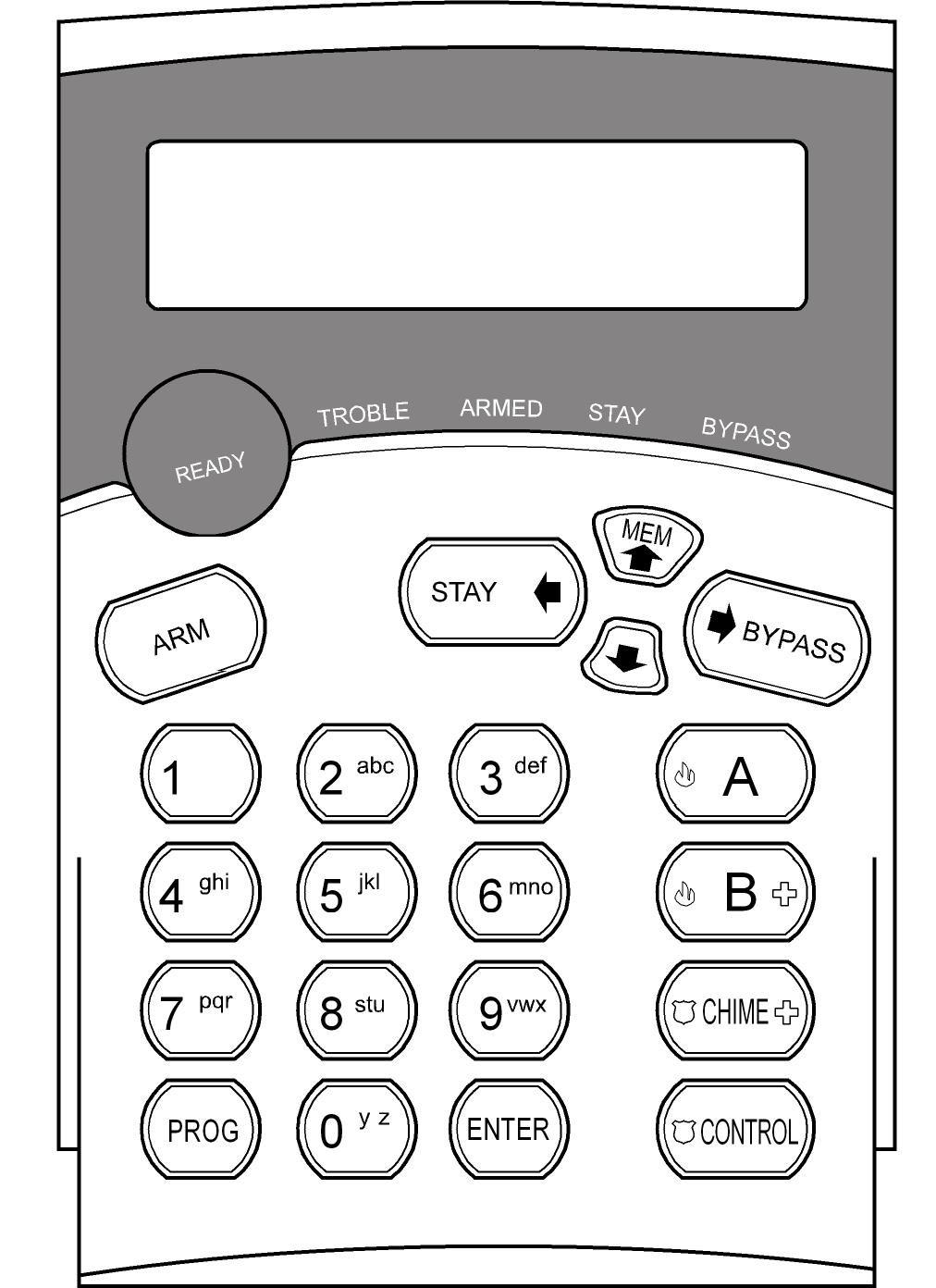
5 Keypad Description General Description The LCD display shows all the information required to operate the system in a friendly manner and free of flaws. The User communicates with the alarm system via the keypad. The Keypad displays continuous information about the status of the alarm system, and enables the User to operate the system in different modes, change settings and program Users' access codes. The keypad also collects and records events to be displayed afterward on request, to overview system activities, and to analyze system performance for diagnostics. The keyboard is illustrated in Figure 1, and the main components are detailed below. 5
6 6
 in response to User activities.")
7 Function Keys Figure 1: Keypad These keys are used to arm the system, enter commands to alter system settings, or scroll through the display. Alphanumeric Keys These keys are used to enter codes, change descriptions of zones, or for programming. Audible Signals The keypad emits signals (beeps) in response to User activities. These signals are listed in Table 1. Table 1: List of Audible Signals Sound Sequence Description Short beep Once only A key in the keypad has been pressed 3 short beeps Once only Operation carried out successfully Long beep Once only Illegal operation, or wrong key pressed Slow beeping Through the Exit or Entry delay time Exit or entry delay warning when arming the system indicates that you must exit the protected area, also Entry delay warning when entering via the entry zone, to disarm the system. 7
8 Indicators The indicators show the status of the system. The LED indicators are listed in Table 2. Table 2: List of LED Indicators Design. Bypass Stay Armed Ready Trouble Function Indicates that there are bypassed zones Indicates that the system is armed in STAY mode Indicates that the system is fully armed, or a partition is armed Indicates that the system is ready to be armed Indicates system failure, or problem. Make note of system message and call service Display The LCD window holds 2 rows of 16 characters each. The display shows: System Messages Open Zones System Status Trouble Messages Memory Events Description of zones Zone numbers during programming Device numbers during control Summary of Functions The system's main functions are listed in Table 3. Table 3: Summary of Functions Function Keys Description Notes Full or Partition Arm C O D E ENTER Initiates full arm Full Arm ARM Initiates full arm Only if enabled by installer 8
9 Disarm during exit ARM Disarms the system during exit delay Only when slow beeping is emitted Disarm C O D E ENTER Disarms the system Stopping Alarms Arm A Partition or B Arm Stay STAY C O D E ENTER Arms partition A or B Initiates partial alarm when the user is home Press A or B for 2 seconds to arm relevant partition Only if enabled by installer Only if enabled by installer Arm Stay STAY Initiates partial alarm when the user is home Disarm Stay C O D E ENTER Disarms the system Disarm Stay STAY Disarms the system Bypass BYPASS Zone # ENTER Bypasses a zone(s) Initiate CHIME CONTROL Activates + Panic emergency alert Initiate Medical Alarm CHIME + B Activates emergency alert Repeats the procedure to unbypass zones Press simultaneously for 2 seconds Press simultaneously for 2 seconds Function Keys Description Notes Initiate Fire A + Alarm Memory MEM B Activates emergency alert Initiates display of events from memory. <ENTER> cancels memory readout Press simultaneously for 2 seconds Displays events, and automatically scrolls to the next event every 2.5 sec. (Use arrow key to scroll up manually) Chime Enable/dis able CHIME Enable or disable chime function Holds the key for 2 sec to alternate. Only if enabled by 9
10 installer Control CONTROL Device# ENTER Activates or deactivates outputs and devices Press <Control> for 2 seconds Change or Add Users' code PROG M CODE ENTER Activates program mode to add or change Users' codes Customize keypad + CONTROL ARM Enters Local Edit Program Mode Increase LCD backlight level CONTROL + STAY Hold <CONTROL> and press <STAY> repeatedly to increase light For details see page 14 Press Control and then Arm, and hold both simultaneously for 2 sec For details see page 16 Decrease LCD backlight level Increase LED backlight level CONTROL + BYPASS CONTROL + MEM Hold <CONTROL> and press <BYPASSS > repeatedly to decrease light Hold <CONTROL> and press <MEM> repeatedly to increase light Function Keys Description Notes Decrease LED backlight level Increase buzzer tone Decrease buzzer tone CONTROL + Hold <CONTROL> and press < > repeatedly to decrease light CONTROL + A Hold <CONTROL> and press <A> repeatedly to increase buzzer tone + CONTROL B Hold <CONTROL> and press <B > repeatedly to lower buzzer tone 10
11 Note: If you started an operation incorrectly, press <ENTER> to exit and return to the previous mode. Operation How to Arm the System before Exit Preparing the System for Arming Verify that the green <Ready> indicator is lit. This indicator is lit only when all zones are closed (all doors, exits and windows are closed and motion in the protected area is restricted or bypassed). If the green <Ready> indicator is not illuminated, the LCD displays the open zones and descriptions. Close open zones, or bypass them. Bypass any zone you cannot close. For details see page 11. Note: Bypassed zones are not protected. Arming the System PowerWave XX DATE When the system is ready, the LCD display shows the system type, date and time, and the green <Ready> indicator is lit. Before leaving premises the system has to be armed. When the system is Ready, enter user code and then <ENTER> to arm the system. Enter Code **** TIME The system prompts you to exit the protected area. There is a exit delay prior to the system being armed. During this delay time you can leave the premises. At the end of the procedure. the ARMED indicator lights up to indicate that the system is armed, and the system message is displayed. (The indicators may go out after a few seconds, depending on the installer's setting). Areas Exiting A - Areas Armed A - Quick Arm When enabled by the installer, press <ARM> to arm the system. During this delay time, a slow beeping is heard to indicate that the system is not armed yet and reminds you to leave the protected area.. 11
12 If you must disarm the system during the exit delay, press <ARM>. Disarming the System Enter User s code and press <ENTER>. The following system message is displayed: Stopping Alarms Areas Disarmed A - Enter User s code and press <ENTER> to stop alarm any time. How to Arm the System when Staying Home Arming the System in Stay Mode This type of arming is used when people are present within the protected area. At night time, when the family is about to retire, perimeter zones are protected, but not the interior zones. Consequently, interior movements will be ignored by the system. When the system is Ready, press <STAY> and the system prompts you to enter user code, and then <ENTER>. Enter Code **** Quick Stay When enabled by the installer, press <STAY> to arm the system. During exit delay you can leave the premises. If you wish to stay or that no one will enter the protected premises, you may cancel the Entry/exit delay by pressing the <ENTER> key. The slow beeping stops and the system is immediately armed. At the end of the procedure, the Stay indicator lights up to indicate that the system is armed and the system message is displayed. (The indicators may go out after a few seconds, depending on the installer's setting). Disarming the System Areas In Stay A - Enter user s code and press <ENTER>, or press <STAY> if enabled by installer. The following system message is displayed. Areas Disarmed A - 12
13 How to Arm Partitions The protected area can be grouped into two separate partitions (e.g. A, B and C ).. The system can be grouped for User s convenience to separate, in a business environment, the offices from the warehouse area, or in a private residence, the different rooms of the home, e.g., living room, bedroom, etc. To arm partition A or B or C see Para Arming the System. If enabled by the installer, to arm the partition A, press <A> for 2 seconds. To arm partition B, press <B > for 2 seconds The same procedure is also applicable to partition B. Areas Exiting - B - During exit delay you can leave premises. At the end of the procedure the ARMED indicator lights up to indicate that the system is armed and system message is displayed. (The indicators may go out after a few seconds, depending on the installer's setting). Areas Armed - B - To disarm partition, see "Disarming the System". Note: to arming partition with code see page 9 How to arm the system before exit How to Bypass Zones Bypass any zone that cannot be closed. You can bypass selected zones prior to arming. It is also used to temporarily exclude a faulty zone from service, which requires repair. To bypass a selected zone, press <BYPASS>, Bypass indicator lights up to indicate that the system is in bypass mode. Enter the zone number (e.g. 01, 05, 12 in PW16 or 1, 2, 6 in PW4/8) one or more zones. Bypass Zones Following press <ENTER>, the system displays the bypassed zones. Zone 3 Bypass Zone 3 13
14 While in the Bypass mode it is possible to bypass more than one zone, press <BYPASS>, Bypass indicator lights up to indicate that the system is in bypass mode, Add the zone number (e.g. 03) one or more zones, following press <ENTER>, the Bypass indicator lights up to indicate zone(s) bypassed. To un-bypass zones, press <BYPASS>, enter zone number (e.g.07,13) and press <ENTER>. Note: Disarming automatically un-bypasses all zones. How to use Chime (If enable by Installer) To disable this function, press <CHIME> for 2 seconds, as shown below. Chime OFF To enable this function, press <CHIME> for 2 seconds, as shown below. Chime ON Emergency Alerts How to initiate Panic Press simultaneously<chime>and <CONTROL> for 2 seconds. How to initiate Medical Alarm Press simultaneously <CHIME> and <B> for 2 seconds. How to initiate Fire Alarm Press simultaneously<a> and <B> for 2 seconds. Generate Threat or Duress If you are compelled to disarm the system under threat, you must enter the duress digit before the user s code to activate the automatic dialer. The duress digit shifts up your usual code by one digit. If your code is 345 and 8 is your duress digit, than entering 8345 will modify your code. The modified duress code will disarm the system in a normal way, but at the same time will activate the dialer silently to report a duress event without arousing suspicion. (For details ask installer.) How to Read System Messages Any system failure that may that may occur, is indicated by system messages. System messages are automatically displayed and are listed in Table 4. Read messages and call for service. Table 4: System Messages Message Description/Action 14
15 Battery Low Main Failure Telephone Line Failure Radio Device Battery Low Supervise Detector Failure Zone Inactivity Time-out Dialer Kiss-off Failure The backup battery is low (charger or battery failure) The main power is disconnected, or caused by power outage. The line is disconnected Replace battery of the particular device Radio detector failed to communicate No movement detected during expected time in this zone Communication fail How to Read Trouble Messages Any failure or -abnormal events that may occur are indicated by trouble messages, and the Trouble indicator is lit. Press <MEM> to read out messages and other events stored in memory. Trouble messages are listed in Table 5. Table 5: Trouble Messages Message Zone Tamper System Tamper Pendant Panic Panic Fire Medical Duress code used Description/Action The tamper of a particular zone Main cabinet open Panic alarm initiated via radio pendant Panic alarm initiated via keyboard Fire alarm initiated via keyboard Medical alarm initiated via keyboard Duress digit pressed by one of the users, under threat How to Display Events from Memory The system memory stores the last events. Press <MEM> to display list of events. The system will display the last event and automatically scroll to the next one every 2.5 seconds, and a beep is emitted. Use the arrow keys to scroll up manually. Each entry shows the type of event, date and time. Wait until all messages are displayed, or press <ENTER> to cancel memory readout. If the message exceeds 16 characters, use the right arrow to read the message. 15
16 How to Control Outputs and Devices The keypad enables control of external devices, such as an air-conditioner or heater. To activate or halt a device, press <CONTROL> for 2 seconds and the number of the device. Up to 8 different devices can be controlled via the keypad. Control Mode When you enter control mode the system prompts you to enter device # and then <ENTER> to activate or deactivate the selected device. User Programming and Customization How to Get into to User Program/Client Mode There are 2 levels of program mode, CLIENT mode and INSTALLER mode. Normally the installer will give you access to the CLIENT mode so you can add, delete, or change the user codes. If you request it your installer can provide you with access to the INSTALLER mode as well. To get into CLIENT mode provided the system is NOT armed Press <PROGRAM> enter Master code and <ENTER>. If you get a single long beep at this point, it means your code cannot access Program mode. How to exit program mode To exit out of program mode press <PROGRAM> and <ENTER>. The LCD display shows the system type, date and time. PowerWave XX DATE TIME How to Change or Add Codes About Master code and User code The factory default master code (123) is intended as a preliminary control of the alarm system. After PowerWave is installed and put into service, the code can be changed to any code known to the Master user. The Master user can define up to 99 user codes. To limit access rights, the holder of the Master code can ask the installer to define several User profiles. Access rights are listed below: - User code has Area A and/or B or C permission 16
17 - User code can arm and/or disarm arm an area - User code can arm and/or disarm arm an area in Stay mode - User code can change its code - User code can change user s code - User code can Operate control Functions - User code can change dialer telephone numbers - User code can alter the real time clock - User can answer an incoming call and start up/down load - User can allow access to installer program mode from client mode. - Initiate Walk-test mode. How to Change Master Code Press <PROG> enter Master code and <ENTER>. The display will show Client Mode. Client Mode Press <PROG> and 1 to change Master code. Use the numeric keyboard to enter your new Master code. The code can hold any combination of 1 to 6 digits. It is recommended using a multi-digit code.. Press <ENTER> to save your new code. To proceed to the next user code, Press <MEM>. Press <PROG> and <ENTER> exit Client Program mode. How to Add or Change User Code In client mode, press <PROG> and the User number (2 to 100) to add or change the code. Use the numeric keyboard to enter the new code. The code can hold any combination of 1 to 6 digits. Press <ENTER> to save your new code. User 3 Code Repeat the procedure for all users or use arrow (MEM) key to advance to next user. Press <PROG> and <ENTER> to exit Local Program mode. How to Delete User Code In client mode, press <PROG> and the User number (2 to 100) you intend to delete. The display shows the code. User 8 Code
18 Press <CONTROL> and<0> simultaneously to delete User code. Press <ENTER> to save the change. Press <PROG> and <ENTER> exit Client Program mode. Customizing your Keypad Local Edit Program mode assists the user to customize descriptions, adjust keypad light and buzzer tone. How to Enter Local Edit Program Mode to Describe Zones To enter this mode, press simultaneously <CONTROL> and <ARM> for 2 seconds. The display will show Local Mode kb #. From hereon, you can change the numeric description of a zone to a textual description. Press <PROG> <1> to change the description of Zone 1. For example, Use the arrow keys to move the cursor forward or backward on the display. Press the corresponding key to replace the current digit. Each key represents 3 different characters. The first character will be shown at the first press, etc. Press <MEM> to change from uppercase to lowercase and visa-a-versa. Zone 1 Bedroom During the programming of text for all of the addresses 1-8,998,999 you can also use the <A> button to return back to last saved text and you can use <B> button to return back to the default text. Press <ENTER> to save textual description. <A..Z> For more zones, press <PROG>, followed by Zone # to continue textual description. The functions of the alpha-numeric keys are listed in Table 6. How to Add or Change Telephone Numbers Your panel will accept up to 6 phone numbers with a total of 16 digits. Your panel can be programmed to dial all or any of these depending on the event which has occurred. (In PW16 The six phone numbers are at program address 331 through to 336). (In PW4/8 The six phone numbers are at program address 501 through to 504). (In FW64 see User's Operating and Programming guide ) While in CLIENT mode, key in the following sequence <PROGRAM> <331> <ENTER> (The address for telephone number 1), The existing number will be flashed out at the 18
19 Keypad then enter <NEW TELEPHONE #> <ENTER> The new numbers will be flashed back to confirm acceptance. At any time you can enter in the address for the telephone number just to view the currently programmed value then press the <PROGRAM> button to move on to another address. Note: In PW16 Address 331 = PH # 1, 332 = PH# 2 to 336 = PH# 6. Note: In PW4/8 Address 501 = PH # 1, 502 = PH# 2 to 504 = PH# 4. How to set Time and Date The alarm system has an internal clock that may be used to automatically Arm or Disarm the alarm or turn Outputs On or off. It is also used to identify when events occurred in memory via the LCD keypad. Should you need to change the Time & Date it must be done from CLIENT mode. To change the Time & Date press In PW16 - Press <PROGRAM> <823> <ENTER> <1-7> <ENTER> In PW4/8 - Press <PROGRAM> <403> <ENTER> <1-7> <ENTER> (In FW64 see User's Operating and Programming guide ) Where 1-7 = the current day (1=Sun, 2 = Mon to 7 = Sat) In PW16 - Press <PROGRAM> <824> <ENTER> <HHMM> <ENTER> In PW4/8 - Press <PROGRAM> <401> <ENTER> <HHMM> <ENTER> Where HH = Hour in 24 Hour Format and MM = Minutes In PW16 - Press <PROGRAM> <825> <ENTER> <1-31> <ENTER> In PW4/8 - Press <PROGRAM> <405> <ENTER> <1-31> <ENTER> Where 1-31 = the current date In PW16 - Press <PROGRAM> <826> <ENTER> <1-12> <ENTER> In PW4/8 - Press <PROGRAM> <406> <ENTER> <1-12> <ENTER> Where 1-12 = the current month In PW16 - Press <PROGRAM> <827> <ENTER> <YY> <ENTER> In PW4/8 - Press <PROGRAM> <407> <ENTER> <YY> <ENTER> Where YY = current year, e.g. 02=2002 How to operate the access control output If the alarm system has been set up to allow control of an electric door lock, you can activate the door release function as follows; Press <CONTROL> or Press <CONTROL> enter CODE then <ENTER> 19
20 The Control LED will lights up while the lock is active and turn off as soon as power is removed from the lock. The Access Control function can either be a single button operation or restricted to requiring a valid User code entry. Both options are shown above. Please consult your installer as to what option may be programmed. How to start Walk test Mode In PW16 only - While in CLIENT mode a User with the proper authority can start walk-test mode. This special mode latches the alarm signals from detectors at the keypad initiating the test so that one person can trigger every detector connected to the alarm then return to the keypad to verify operation. On terminating Walk-test mode the test results are put into the memory buffer so they can be viewed at a later time. To start Walk-test mode while in CLIENT mode press <PROGRAM> <836> <ENTER> The keypad buzzer will beep at 1-second intervals Next trigger every detector connected to the panel then return to the keypad and all of the zones that were triggered will be displayed at the keypad. To terminate Walk-test mode press <ENTER> The keypad will stop beeping and automatically exit CLIENT mode. (In FW64 see User's Operating and Programming guide ) How to Answer an in-coming call In PW16 only - From time to time your installer may need to access the alarm from a remote PC to make changes to your programming and for security reasons they may have configured the alarm so that an authorized person on-site is required to make the alarm system answer the in-coming call. This option is only available in CLIENT mode. To answer an In-coming Call press <PROGRAM> <835> <ENTER> Provided the line connected to the alarm was ringing at the time the panel will now answer the call and allow a remote PC connection. Table 6: Summery of Alphanumeric Keys Button # 1 st Press 2 nd Press 3 rd Press 4 th Press 1 * ( ) # (<) = (>) 1 20
21 2 A (a) B (b) C (c) 2 3 D (d) E (E) F (F) 3 4 G (g) H (h) I (i) 4 5 J (j) K (k) L (l) 5 6 M (m) N (n) O (o) 6 7 P (p) Q (q) R (r) 7 8 S (s) T (t) U (u) 8 9 V (v) W (w) X (x) 9 0 space Y (y) Z (z) 0 How to Program System Description While in Local Edit Program Mode Press <PROG> <999> and then <ENTER>. You may enter any name for your system (up to 16 characters). Name <A..Z> Johnson Family To save changes, press <ENTER>. How to Program Area Description While in Local Edit Program Mode Press <PROG> <998>, and then <ENTER>. You may edit any character, one per each area. Areas <A..Z> ABCDEFGHIJKLMNOP To save changes press <ENTER>. To update and transfer programmed textual information from one LDC keypad to another, press <CHIME> for 2 seconds. To exit Local Edit Program Mode and return to Idle Mode, press <PROG> and then <ENTER>. How to Adjust Keypad Backlight Level The User can adjust the backlight of the keys and LCD display in 16 steps, from Fully illuminated to Off. 21
22 To increase LCD backlight, hold <CONTROL> and press <STAY> repeatedly until the light is increased to its maximum. To decrease LCD backlight, hold <CONTROL> and press <BYPASS> repeatedly until the light goes off. To increase keyboard backlight, hold <CONTROL> and press <MEM> repeatedly until the light is increased to its maximum. To decrease keyboard backlight, hold <CONTROL> and press < > repeatedly until the light goes off. How to Adjust Buzzer Tone The User can adjust the volume of the buzzer tone can be adjusted, in 16 steps, from fully On to Off. To increase the volume, hold <CONTROL> and press <A> repeatedly until it is increased to its maximum. To decrease the volume, hold <CONTROL> and press <B> repeatedly until it is decreased to off. 22
23 Use the following form to record your changes and customizations. User # Name Out put # Device Designation Zone # Zone Name
24 PowerWave LCD Keypad Assignment Each of the 8 possible LCD keypads that can be connected to your PW control Panel must be set to the suitable type of control panel, and addressed individually to avoid bus conflicts. To assign the KEYPAD Address Switch 1 Switch 2 Switch 3 Keypad #1 OFF OFF OFF Keypad #2 ON OFF OFF Keypad #3 OFF ON OFF Keypad #4 ON ON OFF Keypad #5 OFF OFF ON Keypad #6 ON OFF ON Keypad #7 OFF ON ON Keypad #8 ON ON ON To assign type of PowerWave Control Panel 24
25 Switch 5 Switch 6 Switch 7 PW-4 OFF OFF OFF PW-8 ON OFF OFF PW-16 OFF ON OFF PW-64 I ON ON OFF PW-64 II OFF OFF ON To set the Keypad tamper mode Switch 8 Disable Keypad Tamper Enable Keypad Tamper ON OFF 25
PowerWave-16. Users Operating and Programming Guide Version P/N Rev. B N.A July 2002
 ELECTRONIC ENGINEERING LTD. PowerWave-16 16 zone Control panel Communicator Users Operating and Programming Guide Version 6.20 P/N 7121240 Rev. B N.A July 2002 Contents Introduction...4 Meet the Crow Alarm
Elite 16D Version 16 Zone Controller Arrowhead Alarm Products Ltd. Operating Guide. Proudly Designed and Manufactured in New Zealand
 6 Elite 16D Version 16 Zone Controller Arrowhead Alarm Products Ltd Operating Guide 1 Proudly Designed and Manufactured in New Zealand CONTENTS Page No. INTRODUCTION 3 About your Alarm 3 OPERATING YOUR
Elite 64 Version 64 Zone Controller Arrowhead Alarm Products Ltd. Operating Guide. Proudly Designed and Manufactured in New Zealand
 2 Elite 64 Version 64 Zone Controller Arrowhead Alarm Products Ltd Operating Guide Proudly Designed and Manufactured in New Zealand 1 CONTENTS Page No. INTRODUCTION 3 About your Alarm 3 OPERATING YOUR
Contents. Glossary
 Contents Glossary ------------------------------------------------------------------------------------------------------ 6 1. Introduction to the IDS 1632 -------------------------------------------------------------
Elite S Version 8-16 Zone Controller Arrowhead Alarm Products Ltd. Operating Guide. Proudly Designed and Manufactured in New Zealand
 9 Elite S Version 8-16 Zone Controller Arrowhead Alarm Products Ltd Operating Guide Proudly Designed and Manufactured in New Zealand 1 CONTENTS Page No. INTRODUCTION About your Alarm 3 3 OPERATING YOUR
Elite 16D Version 16 Zone Controller Arrowhead Alarm Products Ltd. Operating Guide. Proudly Designed and Manufactured in New Zealand
 5 Elite 16D Version 16 Zone Controller Arrowhead Alarm Products Ltd Operating Guide Proudly Designed and Manufactured in New Zealand About your Alarm Controller Thank you for choosing to protect your premises
Watchguard WGAP864 User Manual
 Watchguard WGAP864 User Manual v1.0 Issued September 2016 1 2 Table of Contents Glossary... 5 1. Introduction to your Watchguard WGAP864... 6 2. Before Operating your Alarm System... 6 3. Understanding
Summit 3208GLD USER MANUAL. Electronics Line
 Summit 3208GLD USER MANUAL Electronics Line Table of Contents 1: Introduction... 2 2: Overview... 3 3: Keypad Functions... 4 3.1: Keypads... 4 3.2: 3108 LCD Keypad Layout... 4 4: Basic System Operation...
IDS S E C U R I T Y IDS816. User Manual MANUAL NO C ISSUED APRIL 2005 VERSION 2.00
 INHEP DIGITAL IDS S E C U R I T Y IDS816 User Manual MANUAL NO. 700-283-01C ISSUED APRIL 2005 VERSION 2.00 Contents 1. Introduction to the IDS816... 4 2. Understanding the Keypad Indicators... 4 3. Programmable
IDS816 User Manual H Issued January 2009
 1 Contents Glossary-------------------------------------------------------------------------------------------------------------------6 1. Introduction to the IDS 816---------------------------------------------------------------------------7
Table of Contents. Appendix A Special Characters 31
 Table of Contents Introduction 2 Section 1: General System Operation 3 1.1 Getting to Know Your System... 3 1.2 How to Arm... 4 1.3 Alternate Arming Methods... 5 1.4 Disarming... 6 1.5 Alarm Memory...
User s Guide. SUB-MA7240O-0001.OG.Solution doc. Created: 6/05/03. Last Updated: 23/09/03. MA7240AO-0001 Version 1.0
 User s Guide SUB-MA7240O-0001.OG.Solution40-111.doc Created: 6/05/03 Last Updated: 23/09/03 MA7240AO-0001 Version 1.0 2 Table Of Contents User List...6 Quick Reference..7 Features...7 Keypad User's Guide...8
IDS S E C U R I T Y IDS816. User Manual MANUAL NO B ISSUED DEC 2004 VERSION 2.00
 INHEP DIGITAL IDS S E C U R I T Y IDS816 User Manual MANUAL NO. 700-283-01 B ISSUED DEC 2004 VERSION 2.00 Contents 1. Introduction to the IDS816... 4 2. Understanding the Keypad Indicators... 4 3. Programmable
User s Information Guide R2A
 Pi HSC505 Home Security Controller User s Information Guide R2A Page 1 of 15 of its development program. 1This document and product are copyrighted and all rights are reserved. Introduction Convention
Understanding the Code Pad lights...4. Code Pad tones...5. Fully arming the system On MODE...6. Fully arming the system - Quick Arm MODE...
 TABLE OF CONTENTS...Glossary of terms...2...code Pad Diagram...3 Understanding the Code Pad lights...4 Code Pad tones...5 Fully arming the system On MODE...6 Fully arming the system - Quick Arm MODE...6
Contents. Glossary Introduction to the IDS Notes Understanding the Keypad Indicators Operation of the Keypad...
 2 Contents Glossary...7 1. Introduction to the IDS805...8 1.1 Notes...8 2. Understanding the Keypad Indicators...8 3. Operation of the Keypad...9 4. System Information...10 4.1 Programmed Functions...10
Alarm Control Panel WIC-16Z4P WIC-5Z2P. User Instructions
 WIC-16Z4P WIC-5Z2P User Instructions Page : 2/14 INDEX # Function Page 1 Add a New User Code 11 2 Arm or Disarm All Areas or Disarm Selected Areas (Partitioned System) 8 3 Arming the System (Away Mode)
Digiplex LED Keypads User s Manual
 KLEDEU03.fm Page -1 Friday, May 4, 2001 11:25 AM Digiplex LED Keypads User s Manual KLEDEU03.fm Page 0 Friday, May 4, 2001 11:25 AM KLEDEU03.fm Page 1 Friday, May 4, 2001 11:25 AM TABLE OF CONTENTS 1.0
D1265. User's Guide. Touchscreen Keypad
 D1265 EN User's Guide Touchscreen Keypad D1265 User's Guide Contents This system includes a telephone line seizure feature. The system can be programmed to communicate with a central monitoring station
VISTA-50P VISTA-50PUL
 Security System User's Manual VISTA-50P VISTA-50PUL N5943-6V1 Rev B 4/99 TABLE OF CONTENTS SYSTEM OVERVIEW...4 General...4 A Partitioned System...4 Zones...4 Fire Protection...5 Burglary Protection...5
IDS S E C U R I T Y IDS816. User Manual. MANUAL NO A ISSUED November 2004 VERSION 1.00
 INHEP DIGITAL IDS S E C U R I T Y IDS816 User Manual MANUAL NO. 700-283-02A ISSUED November 2004 VERSION 1.00 Contents 1. Introduction to the IDS816... 4 2. Understanding the Keypad Indicators... 4 3.
AXI LED USER MANUAL (REV. 1.0)
") Security & Home Automation System AXI LED USER MANUAL (REV. 1.0) CONTENTS PREFACE FEATURES LED KEYPAD OUTLOOK 1.0 LIGHT INDICATION 1 2 4 6 CHAPTER 1: ALARM SYSTEM CONTROL 1.0 USING LED KEYPAD 1.0.1 ARMING
Security & Home Automation System AXI LED USER MANUAL (REV. 1.0) CONTENTS PREFACE FEATURES LED KEYPAD OUTLOOK 1.0 LIGHT INDICATION 1 2 4 6 CHAPTER 1: ALARM SYSTEM CONTROL 1.0 USING LED KEYPAD 1.0.1 ARMING
636 and 646 Keypads. User s Manual
 636 and 646 Keypads 636 646 User s Manual Table Of Contents Basic Operation... 2 Access Codes... 4 Arming & Disarming... 5 Panic Zones... 11 Key Access Programming... 12 Additional Features... 13 Trouble
HILLS Series LED Code Pad User Manual
 HILLS Series LED Code Pad User Manual Not all features may be available on your system Check with your installer to find out which features are programmed Page 2 TABLE OF CONTENTS Code Pad Diagrams...2
Voice Board. Installation and Programming Guide. Runner 4/8,PowerWave 4/8/16 &, Elite64. Add-on Board For Storing Recorded Voice Messages
 ELECTRONIC ENGINEERING LTD. Voice Board Runner 4/8,PowerWave 4/8/16 &, Elite64 Add-on Board For Storing Recorded Voice Messages And listen-in. Installation and Programming Guide. P/N 7101372 Rev. C V.K
&RPPHUFLDO)LUHDQG%XUJODU\ 3DUWLWLRQHG6HFXULW\6\VWHP ZLWK6FKHGXOLQJ
LUHDQG%XUJODU\ 3DUWLWLRQHG6HFXULW\6\VWHP ZLWK6FKHGXOLQJ") 9,67$)% &RPPHUFLDO)LUHDQG%XUJODU\ 3DUWLWLRQHG6HFXULW\6\VWHP ZLWK6FKHGXOLQJ 8VHU*XLGH FIRE FIRE * PULL K3522 3/99 TABLE OF CONTENTS SYSTEM OVERVIEW...4 General...4 A Partitioned System...4 Zones...5 Fire
9,67$)% &RPPHUFLDO)LUHDQG%XUJODU\ 3DUWLWLRQHG6HFXULW\6\VWHP ZLWK6FKHGXOLQJ 8VHU*XLGH FIRE FIRE * PULL K3522 3/99 TABLE OF CONTENTS SYSTEM OVERVIEW...4 General...4 A Partitioned System...4 Zones...5 Fire
L900 series USER MANUAL
 INTRODUCTION The BLUGUARD Control Panel is designed for simple operation yet provides the maximum protection for you. Please read this manual carefully and follow the instructions contained in this book.
VISTA-32FBPT. Commercial Fire and Burglary Partitioned Security Systems with Scheduling. User Guide /12 Rev. B
 VISTA-32FBPT Commercial Fire and Burglary Partitioned Security Systems with Scheduling User Guide 800-11045 2/12 Rev. B 2 TABLE OF CONTENTS SYSTEM OVERVIEW...5 General...5 A Partitioned System...5 Zones...6
SENTROL ZX400/ZX410. Security System Control. Programming
 SENTROL ZX400/ZX410 Security System Control Programming 1 2 TABLE OF CONTENTS Table of Contents Operating the System... 5 Introduction...5 Powering Up With the Control Station...5 Control Stations...6
&RPPHUFLDO%XUJODU\ 3DUWLWLRQHG6HFXULW\6\VWHP ZLWK6FKHGXOLQJ
 READY ARMED READY 1 OFF 7 INSTANT READY 2 AWAY 8 CODE 6BYPASS 9 CHIME 9,67$% &RPPHUFLDO%XUJODU\ 3DUWLWLRQHG6HFXULW\6\VWHP ZLWK6FKHGXOLQJ 8VHU*XLGH ARMED READY 1 OFF 2 AWAY 3 STAY 4 MAX 5 TEST 6 BYPASS
IDS800 USER MANUAL. Summary of Operation. + [ ] 2 IDS800 USER MANUAL NO K ISSUED APR 2003 VER 1.44
![IDS800 USER MANUAL. Summary of Operation. + [ ] 2 IDS800 USER MANUAL NO K ISSUED APR 2003 VER 1.44](/thumbs/89/98095999.jpg "IDS800 USER MANUAL. Summary of Operation. + [ ] 2 IDS800 USER MANUAL NO K ISSUED APR 2003 VER 1.44") Summary of Operation A rm/ disarm [#] + [USER CODE] Quick Quick Quick Away Arm Stay Arm Stay Arm & Go H old down [ 1] for 1 second H old down [ 5] for 1 second H old down [ 6] for 1 second Panic Fire Medical
Summary of Operation A rm/ disarm [#] + [USER CODE] Quick Quick Quick Away Arm Stay Arm Stay Arm & Go H old down [ 1] for 1 second H old down [ 5] for 1 second H old down [ 6] for 1 second Panic Fire Medical
Security System. User Guide for the LED Command Center
 Security System User Guide for the LED Command Center National Security Systems Inc (800)457-1999 MY SECURITY COMPANY IS: CALL BEFORE TEST: THIS SECURITY SYSTEM IS CONNECTED TO TELEPHONE NUMBER: THE SECURITY
**** **** A B ARMED FIRE FIRE C D READY OFF AWAY STAY 2 3 MAXIMUM TEST BYPASS PULL INSTANT CODE CHIME. First Alert READY. * 0 # Professional
 ARMED READY READY )$&&$&% )LUHDQG%XUJODU\ 3DUWLWLRQHG6HFXULW\6\VWHPV ZLWK6FKHGXOLQJ **** **** A B C D FIRE FIRE First Alert OFF AWAY STAY 2 3 1 4 5 6 7 8 9 MAXIMUM TEST BYPASS INSTANT CODE CHIME * 0 #
Version 1.03 January-2002 USER S MANUAL
 Version 1.03 January-2002 1 USER S MANUAL 2 Version 1.03 January-2002 System Details CUSTOMER:...... PHONE:... FAX:... INSTALLED BY:...... PHONE:... FAX:... MAINTENANCE & SERVICE:...... PHONE:... FAX:...
LCD and 16-Zone LED Keypads. User s Manual
 LCD and 16-Zone LED Keypads 1689 1641 16-Zone LED Keypad LCD Keypad User s Manual TABLE OF CONTENTS 1.0 INTRODUCTION...3 2.0 BASIC OPERATION...4 2.1 Keypad Indicator Lights... 4 2.2 Visual Feedback...
Security System With Scheduling. User Guide. N5943-8V4 7/04 Rev A
 ADEMCO VISTA-120 Security System With Scheduling User Guide N5943-8V4 7/04 Rev A Your Honeywell security system is designed for use with devices manufactured or approved by Honeywell for use with your
0 4 / 0 4 / 1 4. GE Concord 4 Quick User Guide. GE Concord 4 Quick User Guide Page 1
 0 4 / 0 4 / 1 4 GE Concord 4 Quick User Guide GE Concord 4 Quick User Guide Page 1 Before Calling Is the keypad beeping? Press *. This will silence the beeping and let you know where the trouble is. Is
Security System. User s Guide for the Text Command Center
 User s Guide for the Text Command Center MY ALARM COMPANY IS: CALL BEFORE TEST: THIS SECURITY SYSTEM IS CONNECTED TO TELEPHONE NUMBER: THE SECURITY CONTROL PANEL IS CONNECTED TO THE PHONE JACK LOCATED:
Ultra-8D. ControlPanel. Operators Manual. Advanced DigitalControls CP108-0M-V1
 Ultra-8D ControlPanel Operators Manual Advanced DigitalControls CP108-0M-V1 ULTRA-8D CONTROL PANEL AS108 OPERATORS MANUAL Copyright 2001 by Advanced Digital Controls NZ Ltd Auckland, New Zealand Document
642 LCD Keypad. User Manual
 642 LCD Keypad User Manual Table of Contents Introduction...1 Legend... 1 Basic Operation...2 Keypad Indicator Lights... 2 Visual Feedback... 2 Auditory Feedback... 3 Info List... 4 Access Codes...5 User
DESTINY 6100 SERIES SECURITY SYSTEM OWNER S MANUAL V1 12/01
 DESTINY 6100 SERIES SECURITY SYSTEM OWNER S MANUAL 800-6006V1 12/01 System Overview General Information Control Panel Detection Devices You have made a wise decision to protect your family and property
DESTINY OWNER S MANUAL
 DESTINY OWNER S MANUAL DESTINY You have made a wise decision to protect your family and property with the DESTINY Security System. The DESTINY has been designed to provide you with a maximum level of security
USER'S GUIDE FA1220CV. 2-Partition Security System N7003-1V2 7/98
 USER'S GUIDE FA1220CV 2-Partition Security System N7003-1V2 7/98 SYSTEM OVERVIEW... 3 General... 3 A Partitioned System... 3 Zones... 3 Burglary Protection... 4 Fire Protection... 4 Alarms... 5 Emergency
Always Armed, Never Disarmed User Guide
 32-Zone Security System Always Armed, Never Disarmed User Guide User Settings For security reasons, write only the user s name and not their user code. 4-Digit Codes 6-Digit Codes User # and Name Byp*
USER GUIDE. PowerMaster-10 G2 Fully supervised wireless alarm control system.
 USER GUIDE PowerMaster-10 G2 Fully supervised wireless alarm control system www.visonic.com PowerMaster-10/30 G2 Version 17 User's Guide Table of Contents 1. Introduction... 3 Preface... 3 Overview...
EasyLoader. End User Manual
 EasyLoader End User Manual Table of Contents Table of Contents... 1 System Configuration... 3 Introduction... 4 SAFETY AND MAINTENANCE INSTRUCTIONS... 4 GLOSSARY... 4 Basic Operations... 8 ARMING YOUR
RUNNER 8/64. 8/64 Zones Control Panel. Program Summary Guide
 RUNNER 8/64 8/64 Zones Control Panel Program Summary Guide SOFTWARE VERSION This manual relates to RUNNER 864 control panels with software version V10.0.115 and above Special Programming Operating Procedures
Program version Alarm Control Panel USER MANUAL GDAŃSK. versa_u_en 03/09
 Alarm Control Panel Program version 1.00 USER MANUAL GDAŃSK versa_u_en 03/09 WARNING To avoid any problems during operation of this control panel, it is recommended that you familiarize yourself with this
/14 Rev. A LYNX Touch L5210 Series
 800-19975 12/14 Rev. A LYNX Touch L5210 Series Your Honeywell security system is designed for use with devices manufactured or approved by Honeywell for use with your security system. Your Honeywell security
10-Zone Spectra LED Keypads
 10-Zone Spectra LED Keypads User s Guide TABLE OF CONTENTS Introduction... 5 Basic Operation... 6 Auditory Feedback... 6 Keypad Indicator Lights... 8 Zone Display... 8 Alarm Memory Display... 8 Trouble
Destiny Destiny Owners Manual
 Destiny 4100 Destiny 4100 Owners Manual TABLE OF CONTENTS INTRODUCTION Control Panel...3 Detection Devices...3 Telephone Keypads...3 GLOSSARY... 4-5 LOCAL PHONE ACCESS Using Your Telephones As Keypads...6
PROGRAMMING PROCEDURES (Table 3)
") CONDOPLEX 2600/2600A/2700 Suite Panel User Manual Document Version 8.4 Oct 19, 1998 Condoplex 1998 PROGRAMMING PROCEDURES (Table 3) FUNCTION PRESS KEYPAD DISPLAY Delete user code or duress code. 0 (hold)
CONDOPLEX 2600/2600A/2700 Suite Panel User Manual Document Version 8.4 Oct 19, 1998 Condoplex 1998 PROGRAMMING PROCEDURES (Table 3) FUNCTION PRESS KEYPAD DISPLAY Delete user code or duress code. 0 (hold)
QUICK USER GUIDE. Alarm Control Panel
 Alarm Control Panel Firmware version 2.10 QUICK USER GUIDE The full version of User Manual and other manuals are available on CD included in the control panel delivery set or on the website www.satel.eu
MG5000 MG5050 SP5500 SP6000 SP7000. User Guide
 MG5000 MG5050 SP5500 SP6000 SP7000 User Guide We hope this product performs to your complete satisfaction. Should you have any questions or comments, please visit www.paradox.com and send us your comments.
Ref.1067/032 Ref.1067/042
 DS1067-033A Mod. 1067 LBT8631 BUS CONTROL PANEL 8/32 INPUTS Ref.1067/032 Ref.1067/042 USER MANUAL TABLE OF CONTENTS 1 PREFACE... 5 2 COMMAND DEVICES... 6 2.1 1067/021 DISPLAY KEYPAD... 6 2.2 ELECTRONIC
Solution Ultima Series Operators Manual ISSUE 1.00
 Solution Ultima Series Operators Manual ISSUE 1.00 Solution Ultima Series Operators Manual Copyright 1998 by, SYDNEY, AUSTRALIA Document Part Number MA488O DOCUMENT ISSUE 1.00 Printed 16 February 1999
LED Keypads D720 Series User s Guide
 LED Keypads D720 Series User s Guide D720 D720W D720B Table of Contents Fire Safety 3 The D720/D720W/D720B Keypad 4 Security System Basics 5 Turning the System On and Off 7 Silencing and Reporting Alarms
SCORPION Z16040C, Z8040C and Z5120C
 SCORPION Z16040C, Z8040C and Z5120C Alarm Controller User Instructions Thank you for choosing to purchase this micron security alarm controller. Micron product is manufactured to exacting quality standards.
Wireless Security System
 Wireless Security System 2GIG-CNTRL2 Operation & User s Guide WARNING: Owner s Instruction Notice Not to be removed by anyone except occupant Technical Support 866-670-1591 www.2gig.com The GO!control
Control Panel. Operators Manual TO SUIT AS216 KEYPAD. AS216-OM-6.2. Advanced Digital Controls
 Control Panel Operators Manual TO SUIT AS216 KEYPAD AS216-OM-6.2 Ultra-16 Control Panel AS216 OPERATORS MANUAL Copyright 2002 by NZ Ltd Auckland, New Zealand Document Part Number: This document is provided
MG5000 MG5050 SP65 SP4000 SP5500 SP6000 SP7000. User Guide. Always Armed, Never Disarmed. Downloaded from manuals search engine
 MG5000 MG5050 SP65 SP4000 SP5500 SP6000 SP7000 Always Armed, Never Disarmed User Guide Warranty For complete warranty information on this product please refer to the Limited Warranty Statement found on
Quick Reference Guide
 infinite Prime with Hybrid Connections User Manual - Version 1.00 Catalog Number: ZI0473A (1/07) All data is subject to change without prior notice. Hereby, Electronics Line 3000 Ltd. declares that this
Digiplex LED Keypads. User s Manual
 Digiplex LED Keypads User s Manual TABLE OF CONTENTS INTRODUCTION... 6 1.1 Legend...6 BASIC OPERATION... 7 2.1 Auditory Feedback (Beep Tones)...8 2.2 Keypad Indicator Lights...8 2.3 LED Keypads...8 2.4
CC880/LP880, SC8016. Operators Guide Solution-16, Solution-16 Safecom
 CC880/LP880, SC8016 EN Operators Guide Solution-16, Solution-16 Safecom CC880/LP880, SC8016 Operators Guide EN 2 Copyright Notice Unless otherwise indicated, this publication is the copyright of Bosch
Master Code Arming Auto-Bypass Option - Home-Away Arming Entry Delay Off Arming
 Master Code The 4 digit Master Code is used for arming and disarming the system, for programming additional access codes, and for changing other features. The Master Code will be supplied to you by your
EVOHD. User Guide. Revision 1.1.
 EVOHD User Guide Revision 1.1 www.paradox.com Warranty For complete warranty information on this product please refer to the Limited Warranty Statement found on the website www.paradox.com/terms. Your
Alarm Control Panel CA-5 USER MANUAL GDAŃSK POLAND. ca5u_e 06/04
 Alarm Control Panel CA-5 USER MANUAL ca5u_e 06/04 GDAŃSK POLAND WARNING In order to avoid any operational problems with the control panel, it is recommended that you become familiar with this manual before
PC4020 v3.2 Instruction Manual
 PC4020 v3.2 Instruction Manual WARNING: This manual contains information on limitations regarding product use and function and information on the limitations as to liability of the manufacturer. The entire
User Guide PowerMaster-10/ PowerMaster-30 Fully supervised wireless alarm control system
 Fully pervised ireless alarm control tem Fully pervised ireless alarm control rol tem Fully pervised User Guide PowerMaster-10/ PowerMaster-30 Fully supervised wireless alarm control system PowerMaster-10
(Updated Defaults) (Covers Ver: 8.64 and above)
 (Covers Ver: 8.64 and above)") Power Wave - 8 8 Zone Alarm Panel V8.71 / 8.72 (Updated Defaults) (Covers Ver: 8.64 and above) Installation Manual 10-December-2003 Crow (Aust) Electronic Engineering Pty Ltd Corporate Head Office: 429
Power Wave - 8 8 Zone Alarm Panel V8.71 / 8.72 (Updated Defaults) (Covers Ver: 8.64 and above) Installation Manual 10-December-2003 Crow (Aust) Electronic Engineering Pty Ltd Corporate Head Office: 429
ADEMCO VISTA-10P ADEMCO VISTA-10PSIA Security Systems
 ADEMCO VISTA-10P ADEMCO VISTA-10PSIA Security Systems User Guide K0736V4 10/08 Rev. B IMPORTANT! PROPER INTRUSION PROTECTION For proper intrusion coverage, sensors should be located at every possible point
Using Your. Security System With LED Keypad S5030, S5031, S5032
 Using Your Security System With LED Keypad S5030, S5031, S5032 Contents 1 Overview Your Security System... 1 How Your Security System Works... 2 Your System's Programming... 3 Getting Used to Your System...
Protégé Eclipse LED Keypad User Manual PRT-KLES
 Protégé Eclipse LED Keypad User Manual PRT-KLES The specifications and descriptions of products and services contained in this manual were correct at the time of printing. Integrated Control Technology
LYNX Touch L5210 Series Security System
 LYNX Touch L5210 Series Security System User Guide 800-19975 12/14 Rev. B LYNX Touch L5210 Series Your Honeywell security system is designed for use with devices manufactured or approved by Honeywell for
/10 Rev A
 VISTA-128BPT/ VISTA-250BPT/ VISTA-128BPTSIA Commercial Burglary Partitioned Security System With Scheduling User Guide 800-06905 6/10 Rev A Your Honeywell security system is designed for use with devices
First Alert 1200C Installer Notes M. Leuck
 First Alert 2C Installer Notes M. Leuck. Programming can done by standard keypads 2. Enter programming with Installer Code + 8 + + 3. Another method of entering programming: Power system down, then back
Proudly Designed and Manufactured in New Zealand. By Arrowhead Alarm Products Ltd
 Proudly Designed and Manufactured in New Zealand By Arrowhead Alarm Products Ltd ARMED = Indicates the System is Armed in Away Mode. STAY = Indicates the System is Armed in Stay Mode. BYPASS = When Flashing,
User's Manual VISTA-40 N7003V1 6/97
 S e c u r i t y S y s t e m User's Manual VISTA-40 N7003V1 6/97 SYSTEM OVERVIEW...3 General...3 A Partitioned System...3 Zones...3 Burglary Protection...4 Fire Protection...4 Alarms...5 Emergency (Panic)
ADEMCO VISTA SERIES User Guide
 ADEMCO VISTA SERIES VISTA-15P VISTA-15PSIA VISTA-20P VISTA-20PSIA User Guide K5309-1V7 3/15 Rev B IMPORTANT! PROPER INTRUSION PROTECTION For proper intrusion coverage, sensors should be located at every
VISTA-128BP/VISTA-250BP/ VISTA-128SIA Enhanced Commercial Burglary Partitioned Security System With Scheduling User Guide K5895V5 4/09 Rev C
 VISTA-128BP/VISTA-250BP/ VISTA-128SIA Enhanced Commercial Burglary Partitioned Security System With Scheduling User Guide K5895V5 4/09 Rev C Your Honeywell security system is designed for use with devices
Wireless Keypads LKP(E)S8M Series
S8M Series") Wireless Keypads LKP(E)S8M Series User manual Contents Congratulations on your purchase of this Honeywell wireless keypad. To make the best out of your equipment we advise you to read this manual carefully.
Wireless Keypads LKP(E)S8M Series User manual Contents Congratulations on your purchase of this Honeywell wireless keypad. To make the best out of your equipment we advise you to read this manual carefully.
Property of Monitronics Inc
 Enter Program Press CODE key + * + 2468 + 1 (also try 2121) Installer Options Move to location Program location Exit Program Default Panel Hex Program Code + * + Installer Code + 1 = Enter Programming
&RPPHUFLDO%XUJODU\ 3DUWLWLRQHG6HFXULW\6\VWHP ZLWK6FKHGXOLQJ
 READY ARMED READY 1 OFF 7 INSTANT 2 AWAY 8 CODE 6BYPASS 9 CHIME 9,67$%3 9,67$%3 &RPPHUFLDO%XUJODU\ 3DUWLWLRQHG6HFXULW\6\VWHP ZLWK6FKHGXOLQJ 8VHU*XLGH ARMED READY 1 OFF 2 AWAY 3 STAY 4 MAX 5 TEST 6 BYPASS
VISTA-20PMT. Security. Systems. User s Guide. Monitronics
 VISTA-15PMT VISTA-20PMT Security Systems User s Guide Monitronics R I N T E R N A T I O N A L, I N C. K5309-1MTV2 7/04 Rev. A Reference: MTV15P, MTV20P IMPORTANT! PROPER INTRUSION PROTECTION For proper
PC4020 v3.5 Instruction Manual
 PC4020 v3.5 Instruction Manual WARNING: This manual contains information on limitations regarding product use and function and information on the limitations as to liability of the manufacturer. The entire
2000 SERIES DIAGNOSTIC ALARM CONTROL SYSTEM
 2000 SERIES DIAGNOSTIC ALARM CONTROL SYSTEM OPERATING INSTRUCTIONS MODELS: 2300 2500 2700 This information is relevant to systems fitted with Issue 4.1 (or later) Master Keypad Software, also to Networked
3 User s settings. 3.3 Internal clock setting
 2.9 Subsystem arming In a large building a sub control panel can be enrolled to the JA-63. The subsystem reports all alarms and failures to the main system. The installer can program if the systems will
9,67$36HULHV 6HFXULW\6\VWHPV 8VHU*XLGH K5309-1V1 7/02
 9,67$3366HULHV 9,67$36HULHV 6HFXULW\6\VWHPV 8VHU*XLGH K5309-1V1 7/02 IMPORTANT! PROPER INTRUSION PROTECTION For proper intrusion coverage, sensors should be located at every possible point of entry to
User's Manual 5120XM N8031 6/96
 Fire and Burglary System User's Manual 5120XM N8031 6/96 SYSTEM OVERVIEW...3 General...3 Zones...3 Fire & Emergency Protection...3 Burglary Protection...4 Alarms...4 Memory of Alarm...4 ABOUT THE KEYPADS...5
ICP-CC488 ICP-CC488 EN. Control Panel. User s Guide
 ICP-CC488 EN User s Guide ICP-CC488 Control Panel ICP-CC488 User's Guide Notices EN 2 Copyright Notice Unless otherwise indicated, this publication is the copyright of Bosch Security Systems, Inc. ( Bosch
Tomorrow s technology for today s security needs.
 Tomorrow s technology for today s security needs. The Security Command Keypad Welcome Congratulations on your decision to purchase a Security Command system. The new Security Command keypad, from one of
$'(0&2 9,67$ 3DUWLWLRQHG 6HFXULW\ 6\VWHP 8VHU *XLGH N7003V3 5/04 Rev A
 $'(0&29,67$ 3DUWLWLRQHG6HFXULW\6\VWHP 8VHU*XLGH N7003V3 5/04 Rev A 2 TABLE OF CONTENTS SYSTEM OVERVIEW...5 General...5 A Partitioned System...5 Zones...5 Fire Protection...6 Burglary Protection...6 Alarms...6
LYNX Touch Security System
 LYNX Touch Security System User Guide 1:35 2 PM October 26, 2011 72 Mostly Sunny 68 F F Feels Like 71 Security Messages Automation 5-Day Forecast News Traffic 800-10615 1/12 Rev. A LYNX Touch L5100 Series
Condominium Security Management System
 User Access Codes The CONDOPLEX series panels can be programmed with nine (9) different user codes and one (1) duress code. User codes are normally used for arming and disarming the panel. The duress code
32-Zone Wireless Transceiver Control Panel MG5000. User s Guide
 32-Zone Wireless Transceiver Control Panel MG5000 MG32LED MG32LRF MG10LEDH MG10LEDV User s Guide We hope this product performs to your complete satisfaction. Should you have any questions or comments,
User s Guide FA168CPS / FA168CPSSIA FA148CP / FA148CPSIA. K5309-5V5 11/08 Rev. A OFF 3 STAY 2 AWAY 1 OFF A B C D 5 TEST 8 CODE 9 CHIME FA260 # FA560
 MAX INSTANT READY R BYPASS AWAY STAY PAGE ARMED READY 1 OFF MAX INSTANT READY R 2 AWAY 3 STAY BYPASS 9 CHIME FA168CPS / FA168CPSSIA FA148CP / FA148CPSIA Security Systems ARMED READY A B C D 7 4 1 2 3 OFF
PROGRAMMING GUIDE SPECTRA CONTROL PANELS V , 1725EX, 1728 AND 1728EX 1755, 1755EX, 1758, AND 1758EX
 PROGRAMMING GUIDE SPECTRA CONTROL PANELS V1.2 1725, 1725EX, 1728 AND 1728EX 1755, 1755EX, 1758, AND 1758EX TABLE OF CONTENTS HOW DO I PROGRAM THE SYSTEM?... 4 Single Digit Data Entry Method (Hexadecimal
NX-148 LCD CODE PAD TABLE OF CONTENTS
 NX-148 LCD CODE PAD TABLE OF CONTENTS Glossary Of Terms... 4 Understanding The Lights... 5 Code Pad Functions Arming In The ON Mode... 6 Making The System Ready To Arm... 7 Using Quick Arm... 7 Arming
ALARM SYSTEM USER S MANUAL Rev
 ALARM SYSTEM USER S MANUAL Rev.06 890-00011 Manufacturer: Viatron Electronics 3514 1st Street, St-Hubert (Quebec) Canada J3Y 8Y5 WARNINGS the warranty can be void if the Agri-Alert 2400 is used in a manner
BENTEL SECURITY srl reserves the right to modify the technical specifications of this product without prior notice.
 BENTEL SECURITY srl reserves the right to modify the technical specifications of this product without prior notice. via Florida - Z.I. Valtesino - 63013 GROTTAMMARE (AP) - ITALY USER MANUAL: Digital communicator