Operating Instructions VWR Air Jacketed CO2 Incubator
|
|
|
- Rudolph Gardner
- 6 years ago
- Views:
Transcription

1 Operating Instructions VWR Air Jacketed CO2 Incubator
2 Preface VWR Catalogue Number Manufacturer Model Number Sensor* Capacity (cu ft) Voltage VWR T/C V/60Hz VWR IR V/60Hz VWR T/C 6.5 X 2** 115V/60Hz VWR IR 6.5 x 2** 115V/60Hz *T/C is a thermal conductivity sensor. IR is an infra-red sensor. **Dual stack Legal Address of Manufacturer United States VWR International, LLC 100 Matsonford Rd Radnor, PA Country of origin: United States MANUAL NUMBER /12/16 Original ccs REV ECR/ECN DATE DESCRIPTION By VWR International Air Jacketed CO2 Incubator i
3 Preface CAUTION Contains Parts and Assemblies Susceptible to Damage by Electrostatic Discharge (ESD) Important Read this instruction manual. Failure to read, understand and follow the instructions in this manual may result in damage to the unit, injury to operating personnel, and poor equipment performance. s Caution All internal adjustments and maintenance must be performed by qualified service personnel. s Material in this manual is for information purposes only. The contents and the product it describes are subject to change without notice. VWR International makes no representations or warranties with respect to this manual. In no event shall VWR be held liable for any damages, direct or incidental, arising out of related to the use of this manual. Intended Use: The VWR Air Jacketed CO2 Incubators are designed to maintain an optimal environment for the incubation of tissue and cell samples. These models are designed to maintain temperature and carbon dioxide levels as set by the operator as well as monitoring chamber relative humidity. CO2 is controlled using either a thermoconductivity cell, or an infra-red sensor. The VWR Air Jacketed Incubators are approved for general purpose use only. Non-intended Use: The VWR Air Jacketed Incubators are not intended for use where electrical or physical contact with the patient is established. These incubators are not intended to be operated in potentially explosive environments and are not intended for use with flammable materials. The VWR Air Jacketed Incubators are not intended for use as a Microbiological Incubator (21 CFR ) and are also not approved for use in assisted reproductive procedures for the incubation of ova and embryos (21 CFR ). Warning If the incubator is not used in the manner specified in this operating manual, the protection provided by the equipment design may be impaired. s 2015 VWR International. All rights reserved. ii Air Jacketed CO2 Incubator VWR International
4 Preface Important operating and/or maintenance instructions. Read the accompanying text carefully. Potential electrical hazards. Only qualified persons should perform procedures associated with this symbol. Equipment being maintained or serviced must be turned off and locked off to prevent possible injury. Hot surface(s) present which may cause burns to unprotected skin, or to materials which may be damaged by elevated temperatures. 4 Always use the proper protective equipment (clothing, gloves, goggles, etc.) 4 Always dissipate extreme cold or heat and wear protective clothing. 4 Always follow good hygiene practices. 4 Each individual is responsible for his or her own safety. VWR International Air Jacketed CO2 Incubator iii
5 Preface Do You Need Information or Assistance on VWR International Products? VWR can provide information on pricing and give you quotations. We can take your order and provide delivery information on major equipment items or make arrangements to have your local sales representative contact your. Our products are listed on the internet and we can be contacted through our Internet home page. Visit VWR's website at vwr.com for: Complete technical service contact information Access to VWR's Online Catalogue, and information about accessories and related products Additional product information and special offers For information or technical assistance, contact your local VWR representative, or visit vwr.com. VWR can supply technical information about proper setup, operation or troubleshooting of your equipment. We can fill your needs for replacement parts or provide you with on-site service. We can also provide you with a quotation on our Extended Maintenance Program for your products. Whatever VWR products you need or use, we will be happy to discuss your applications. If you are experiencing technical problems, working together, we will help you locate the problem and, chances are, correct it yourself...over the telephone without a service call. When more extensive service is necessary, we will assist you with direct factory trained technicians or a qualified service organization for on-the-spot repair. If your service need is covered by the VWR International warranty, we will arrange for the unit to be repaired at our expense and to your satisfaction. iv Air Jacketed CO2 Incubator VWR International
6 Table of Contents Section 1 Section 2 Section 3 Installation and Start-Up Keypad Operation Displays Installing the Incubator Stacking the Incubators Preliminary Cleaning Duct Sheets and Shelf Installation Access Port Filter & CO2 Sensor Cover Plate Air Sample Filter Installation HEPA Filter Installation Leveling the Unit Electrical Power Connection Filling the Humidity Pan Connecting the CO2 Gas Supply Incubator Start-Up Calibration Temperature Thermal Conductivity CO2 System Infrared CO2 System Configuration Turn Audible Alarm ON/OFF New HEPA Filter Set REPLACE HEPA filter reminder Set Access Code Enable Low Temp Alarm to Trip Contacts Set Low Temp Alarm Limit (tracking alarm) Set High CO2 Alarm Limit (tracking alarm) Set Low CO2 Alarm Limit (tracking alarm) Set New Zero Number for T/C CO2 Sensors Enable CO2 Alarms to Trip Contacts Set New Span Number for T/C CO2 Sensors VWR International Air Jacketed CO2 Incubator v
7 Table of Contents Section 4 Section 5 Section 6 Section 7 Section 8 Section 9 Alarms Temp Controller Failure TMP CNTR ERR Sensor Fault Alarms Preventive Maintenance Routine Maintenance Clean Cabinet Exterior Replace Power Fuses HEPA Filter Maintenance Clean Glass Doors Clean Humidity Pan Replace Air Sample Filter Electronics Section Sterilization Cycle Factory Options Remote Alarms Specifications Customer Installed Accessories and Parts Exploded Part Drawing Warranty Information vi Air Jacketed CO2 Incubator VWR International
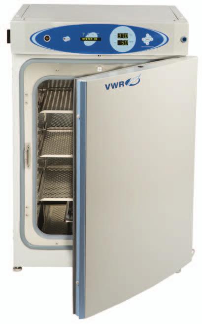
8 Section 1 Installation and Start-Up See Section 1. Chamber gas sample port Main power switch Control panel Sterilization Cycle button Inner door Leveling legs (4) Door heater cable See Section 5. Figure 1-1. Components Chamber Gas Sample Port - Used for sampling chamber CO2 content using a FYRITE or similar instrument. Main Power Switch - Mains Disconnect Control Panel - Keypad, displays & indicators (Figure 1-2) Leveling Legs - Used to level the unit Sterilization Cycle Button - Switch to initiate sterilization cycle Note The incubators are stackable. Information follows. s VWR International Air Jacketed CO2 Incubator 1-1
9 Section 1 Installation and Start-Up Silence Switch: Press to mute audible alarm. See Section 4 for alarm ringback times. Visual Alarm Indicator - Lights pulses on/off during an alarm condition. MODE Select - Used to select Run, Setpoints, Calibration and Configuration modes. Message Display - Shows system status. Mode Select Indicators - RUN: Run Menu SET: Set Points Menu CAL: Calibration Menu CON: Configuration Menu HEAT Indicator - Lights when heaters are activated. Injection INJ Indicator - Lights during CO2 injection into chamber. Temp [T ( C)] Display - Programmable to display temperature. See Configuration section. CO2 [CO2 (%)] Display - Programmable to display CO2 percentage. See Configuration section. Visual Alarm Indicator Mute Mode Select MODE Mode Select Indicators Heat Indicator RUN SET CAL CON Message Display HEAT INJ Temp Display T ( C) CO 2 (%) Up/Down Arrows ENTER Enter Injection Indicator CO2 Display SCROLL FOR PARAMETERS Scroll for Parameters Arrows Figure 1-2. Control Panel 1-2 Air Jacketed CO2 Incubator VWR International
10 Section 1 Installation and Start-Up Keypad Operation The VWR Air Jacketed Incubator has four basic modes for incubator setup: Run, Setpoints, Calibration and Configuration. Run is the default mode for normal operation. Set is used to enter system setpoints for incubator operation. Calibration is used to calibrate various system parameters. Configuration allows for custom setup of various options. Table 1-1. Selections Under Each Mode RUN SETPOINT CALIBRATION CONFIGURATION Default Mode Temperature Temp Offset Audible Overtemp CO2 Cal 1 New HEPA Timer CO2 IR Cal 2 Replace HEPA Reminder 1 T/C units Base Unit Displays 2 IR units Option Unit Displays *T/C units only Access Code Temp Lo Alarm Temp Relay CO2 Lo Alarm CO2 Hi Alarm CO2 Relay CO2 Z & S #'s * Display Temp Display RH Scroll Keys: Steps the operator through parameters of SET, CAL and CON modes. The right arrow goes to the next parameter, the left arrow returns to the previous parameter. Up/Down Keys: Increases/decreases or toggles the parameter value selected in SET, CAL, and CON modes. ENTER: Must press this key to save-to-memory all changed values. VWR International Air Jacketed CO2 Incubator 1-3
11 Section 1 Installation and Start-Up Displays Message Display: Shows system status (Mode) at all times. Shows CLASS 100 or SYSTEM OK during normal operation, or alarm messages if the system detects an alarm condition (see Section 4, Alarms). The message CLASS 100 is a timing mechanism indicating that, under normal operating conditions with the HEPA filter installed, the air inside the chamber meets the Class 100 air cleanliness standard for particulates of 0.5 micron size or larger per cubic foot of air. Upper and Lower Displays: The 7 segment upper display shows temperature. The lower display shows CO2. Installing the Incubator 1. Maintain a minimum three inch clearance behind the incubator for electrical and gas hook-ups. In addition, a three inch ventilation space is needed on each side. 2. Locate the unit on a firm level surface capable of supporting the unit weight of 260 lbs (118kg). 3. Locate the unit away from doors and windows and heating and air conditioning ducts. 4. Lift the unit by the sides of the cabinet base. Do not attempt to lift it by the front and back. This places stress on the outer door hinges. Stacking the Incubators Warning Install stacked units against a wall or similar structure. s Warning With incubators in a stacked configuration, do not leave both exterior doors open at the same time. s Warning If the units have been in operation, turn them both off and disconnect the power source before beginning any service work. s Two stacking brackets (shown at left) are included in the parts bag shipped with each incubator. Figure 1-3. Stacking Brackets 1-4 Air Jacketed CO2 Incubator VWR International
12 Section 1 Installation and Start-Up Stacking Incubators (continued) 1. Remove the cover plate securing the door cord from the incubator to be on top. See Figure 1-4. Disconnect the plug from the connector. 2. Remove the four screws securing the door hinges to the unit. Remove the door and set it aside. 3. Unscrew the two hole plugs from the top cover of the incubator to be the bottom of the stack (Figure 1-5). Cover plate and bolt hole with door connector Figure 1-4. Cover Plate Figure 1-5. Hole Plug Locations 4. Unscrew and remove the 4 leveling feet from the unit to be stacked on top and lift it onto the bottom unit. Align all sides. Warning This incubator weighs 260 lbs (118kg). Have sufficient personnel available when lifting. Lift the unit by the sides of the cabinet base to avoid placing stress on the outer door hinge. s 5. Insert the stacking brackets into the slots at the back of the stacked units as shown in Figure Align the slotted holes in the brackets with the mounting holes on the back of the top Figure 1-6. Stacked incubator. Secure the brackets with the screws and washers provided in the parts bag. See Figure 1-8. Top incubator back Top unit Bottom unit Stacking bracket Stacking bracket Bottom incubator back Figure 1-7. Bracket into Slot Figure 1-8. Installed Brackets on Back of Unit VWR International Air Jacketed CO2 Incubator 1-5
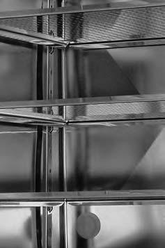
13 Section 1 Installation and Start-Up Stacking Incubators (continued) 7. Thread one 1/4 x 20 bolt and washer included with the stacking brackets, into the hole behind the cover plate. Do not tighten. Refer to Figure Remove the cover plate from the same area on the other side of the top unit. 9. Thread the other 1/4 x 20 bolt and washer into this hole. 10. Tighten the bolts on both sides. Cover plate and bolt hole with door connector Figure 1-9. Bolt Hole 11. Assemble the door hinges to the unit. Secure with the screws. 12. Plug the door cord into the connector, as previously. Secure the cover plate. 13. Install the cover plate on the other side of the unit. The stacked incubators are ready for service. Preliminary Cleaning 1. Remove vinyl from shelf channels, duct sheets, and air duct, if present. 2. Using a suitable laboratory disinfectant, clean all interior surfaces. Caution Before using any cleaning or decontamination method except those recommended by the manufacturer, users should check with the manufacturer that the proposed method will not damage the equipment. Accidental spills of hazardous materials on or inside this unit are the responsibility of the user. s Duct Sheet and Shelf Installation 1. Installed included grommets into the back flange of each duct sheet; 6 grommets per sheet. See Figure Install the side ducts with the tabs facing into the center of the chamber with their slots up. There are no right side or left side ducts, simply rotate one of them to fit the opposite side. Tilt the side ducts as they are placed into the chamber so the tops fit into the top air duct, then guide them into the vertical position. Figure 1-11 shows the side duct as it would be oriented for the right side of the chamber. Figure Grommets on back of duct sheet 1-6 Air Jacketed CO2 Incubator VWR International
14 Section 1 Installation and Start-Up Duct Sheet and Shelf Installation (continued) 3. Referring to Figure 1-11, note that there is no difference in the left and right shelf channels. 4. Install the shelf channels by placing the channel s rear slot over the appropriate rear tab on the side duct. Pull the shelf channel forward and engage the channel s front slot into the side duct s appropriate forward tab. Refer to Figure Side toward side duct Shelf Channels Side toward shelf Side Duct Right Side Duct with Shelf Channel Installed Figure Shelf Channels & Side Ducts Shelf channel rear slot Side duct tab Side duct tab Shelf channel front slot Figure Channels and Slots 5. Figure 1-11 shows one of the channels installed on the right side duct. 6. Locate the supplied rod, spring and end pieces; 4 each. Assemble the spring to the rod by positioning the very end of the spring over the ridge at the rod. Then press the spring to the opposite side. It should snap into place. See Figures 1-13 and Spring end Ridge Figure Spring End Figure Spring Assemble to Rod 7. Slide end cap over spring (Figure 1-15). Note When installing the rods, the spring end can be installed on either side of the chamber. The upper front rod is high in the chamber and the upper back rod is lower to allow access to the access port filter door. Figure Spring End VWR International Air Jacketed CO2 Incubator 1-7
15 Section 1 Installation and Start-Up Installing Duct Sheets and Shelves (cont.) 8. Install one end of the rod into the appropriate hole in the duct sheet. 9. Compress the spring (under the end cap) to insert the other end of the rod into the hole in the duct sheet on the opposite side. Front opening of chamber 10. Figure 1-16 shows the four rods installed. Back wall of chamber Note Using the supplied spring rods will ensure the side ducts are the proper distance needed for shelves to move freely. s Figure Four Rods Installed in Chamber Access Port Filter & CO2 Sensor Cover Plate 1. Locate the opening in the top left corner of the interior chamber. Remove the tape from the opening on the outside of the unit. 2. Locate the stopper with filter in the hardware bag. Lift the metal port cover and install the assembly in the opening inside the chamber. See Figure Also in the hardware bag is the CO2 sensor cover plate. Install, using the 1/4-turn fasteners. Refer to Figure 1-17 for the location. Thumbscrews HEPA Filter Access Port Filter and stopper assembly Air Sample Filter CO2 Sensor Cover Plate Figure Filter and Plate 1-8 Air Jacketed CO2 Incubator VWR International
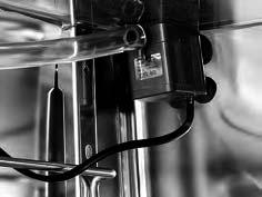
16 Air Sample Filter Installation 1. Remove the filter from the shipping bag. 2. Install the air sample filter assembly to the black hose barb behind the top duct. 3. Insert the other end of the filter assembly onto the metal tubing on the top duct. Refer to the Figure metal tubing Air Sample Filter Section 1 Installation ans Start-Up HEPA collar hose barb behind top duct Figure Air Sample Filter Installation HEPA Filter Installation Caution Be careful when the filter. The media can be damaged if it is mishandled. To avoid damage to the incubator, do not operate the unit without the HEPA filter in place. s 1. Remove the filter from the shipping box. 2. Remove the plastic coating from the filter, using caution not to touch the filter media. 3. Install the filter as shown in Figure Refer to Section 5 for HEPA filter maintenance. Caution The media of the filter can be damaged if mishandled. To avoid damage to the incubator, do not operate the unit without the HEPA filter in place. s Leveling the Unit Check the unit for being level by placing a bubble-style level on one of the shelves. Turn the hex nut on the leveler counterclockwise to lengthen the leg or clockwise to shorten it. Level the unit front-to-back and left-toright. Electrical Power Connection See the serial tag on the side of the unit for electrical specifications or refer to the electrical schematics at the end of this manual. Caution Serial tag rating is based on amperage draw during sterilization cycle. Normal operating amperage is much less. Ensure that electrical circuit will handle amp draw of sterilization cycle. Connect the incubator to a grounded, dedicated circuit. The power cord connector is the mains disconnect device for the incubator. Position the unit so that it can be easily disconnected. s VWR International Air Jacketed CO2 Incubator 1-9
17 2 2 Section 1 Installation and Start-Up Electrical Power Connection (cont.) Plug the provided power cord into the power inlet connector on the back of the cabinet (Figure 1-19), then into the grounded, dedicated, electrical circuit. Accessory Outlet 75 watts max ACCESSORY 75 WATTS MAX. RS 485 #2 CO inject 15 p.s.i. Regulated (103.4 kpa) #1 CO inject 15 p.s.i. Regulated (103.4 kpa) ALARM CONTACTS 30V MAX / 1A MAX a Remote Alarm Contacts 30V max/1a max CO2 Inlet #1 Tank b Air Intake Power Cord Connector a RJ-ll telephone style connectors b IR CO units only 2 Figure Back of Cabinet Filling the Humidity Pan Fill the humidity pan with sterile distilled water to within 1/2 of the top. Place the pan directly in the center of the incubator floor. For applications requiring high humidity, the pan should be placed against the left side wall of the incubator. The side ducts have been modified to allow the pan to be placed against the wall. Optimum humidity is achieved by capping the CO2 sample port. This will, however, cause condensation in the chamber. To enhance RH recovery from door openings, place a second humidity pan in the right side duct. For best operation of the incubator, sterilized distilled, demineralized or de-ionized water should be used in the humidity pan. Water purity should be in the resistance range of 50K to 1M Ohm/cm, or a conductivity range of 20.0 to 1.0 us/cm. Refer to ASTM Standard D or D for measuring water purity. Distillation systems, as well as some types of reverse osmosis water purity systems, can produce water in the quality range specified. Tap water is not recommended as it may contain chlorine, which can deteriorate the stainless steel. Tap water may also have a high mineral content, which would produce a build-up of scale in the pan. High purity or ultra pure water is not recommended as it is an extremely aggressive solvent and will deteriorate the stainless steel Air Jacketed CO2 Incubator VWR International
18 Section 1 Installation and Start-Up Filling the Humidity Pan (continued) High purity water has a resistance of above 1M to 18M Ohm. Even high purity water can contain bacteria and organic contaminants. Water should always be sterilized or treated with a decontaminant, safe for use with stainless steel as well as safe for the product, prior to being introduced into the humidity pan. Check the level and change the water frequently to avoid contamination. Do not allow the water level to fluctuate significantly. Dry-outs will have an adverse effect on the humidity level and CO2 calibration of the T/C units. Caution Use of chlorinated water, or decontamination products containing chlorine, will deteriorate the stainless steel and cause rust, voiding the warranty. s Connecting the CO2 Gas Supply Warning High concentrations of CO2 gas can cause asphyxiation! OSHA Standards specify that employee exposure to carbon dioxide in any eighthour shift of a 40-hour work week shall not exceed the eight-hour time weighted average of 5000 PPM (0.5% CO2). The short term exposure limit for 15 minutes or less is 30,000 ppm (3% CO2). Carbon dioxide monitors are recommended for confined areas where concentrations of carbon dioxide gas can accumulate. s Warning This incubator is designed to be operated with CO2 gas only. Connecting a flammable or toxic gas can result in a hazardous condition. Gases other than CO2 should not be connected to this equipment. CO2 gas cylinders have a UN1013 label on the cylinder and are equipped with a CGA 320 outlet valve. Check the gas cylinder for the proper identification labels. The CO2 gas supply being connected to the incubator should be industrial grade, 99.5% pure. Do not use CO2 gas cylinders equipped with siphon tubes. A siphon tube is used to extract liquid CO2 from the cylinder which can damage the pressure regulator. Consult with your gas supplier to ensure that the CO2 cylinder does not contain a siphon tube. Gas cylinders should also be secured to a wall or other stationary object to prevent them from tipping. A two-stage CO2 pressure regulator is required to be installed on the outlet valve of the gas cylinder. Input pressure to the incubator must be maintained at 15 psig (103.4 kpa) for proper performance of the CO2 control system. A single stage CO2 pressure regulator will not maintain 15 psig (103.4 kpa) to the incubator as the pressure in the CO2 cylinder decreases; therefore, a two stage regulator is recommended. VWR International Air Jacketed CO2 Incubator 1-11
19 Section 1 Installation and Start-Up Connecting CO2 Gas Supply (continued) Warning If higher purity CO2 is desired inside the incubator (greater than 99.5% pure), the pressure regulator should be constructed with a stainless steel diaphragm, along with specifying the purity of the CO2 from the gas supplier. Follow the manufacturer s instructions to ensure proper and safe installation of the pressure regulator on the gas cylinder. Consult your facility safety officer to ensure that the equipment is installed in accordance with the codes and regulations that are applicable in your area. s The CO2 gas supply being connected should be industrial grade 99.5% pure and should not contain siphon tubes. Install a two-stage pressure regulator at the cylinder outlet. The high pressure gauge at the tank should have psig range. The low pressure gauge, at the incubator inlet, should have a 0-30 psig range. Input pressure to the incubator must be maintained at 15 psig (103.4 kpa). The incubator has serrated fittings on the back of the cabinet to connect the gas supply. Refer to Figure The fitting is labeled CO2 Inlet #1 Tank. Make sure that the connections are secured with clamps. Check all fittings for leaks. Incubator Start-Up With the incubator properly installed and connected to power, the humidity pan filled, and the unit connected to gas supplies, system setpoints can be entered. The following setpoints can be entered in SET mode: Temperature, Overtemperature and CO2. To enter SET mode, press the MODE key until the SET indicator lights. Press the right and/or left arrow keys until the proper parameter appears in the message display. See Chart 1-1 for more detail. Setting the Operating Temperature All VWR Air Jacketed Incubators have an operating temperature range of 10 C to 50 C, depending on ambient temperature. The incubator is shipped from the factory with a temperature setpoint of 10 C. At this setting, all heaters are turned off. To change the operating temperature setpoint: 1. Press the MODE key until the SET indicator lights. 2. Press the right arrow until Temp XX.X is displayed in the message display. 3. Press the up/down arrow key until the desired temperature setpoint is displayed Air Jacketed CO2 Incubator VWR International
20 Section 1 Installation and Start-Up Setting the Operating Temperature (continued) 4. Press ENTER to save the setpoint. 5. Press the MODE key until the RUN indicator lights for RUN mode or press the right/left arrow keys to go to next/previous parameter. Setting the Overtemp Setpoint Caution The independent overtemp system is designed as a safety to protect the incubator only. It is not intended to protect or limit the maximum temperature of the cell cultures or customer s equipment inside the incubator if an overtemp condition occurs. s VWR Air Jacketed Incubators are equipped with a secondary temperature monitoring system to monitor the air temperature inside the cabinet. This system is designed as a safety device to turn off all heaters in the event of a temperature control failure. Temperature control in the incubator will be ±1 of the overtemp setpoint. The overtemperature is set by the factory (default) at 40 C. However, the overtemp can be set up to 55 C in 0.5 increments. If the incubator s operating temperature setpoint is set above the overtemp setpoint, the overtemp setpoint will automatically update to 1 C above the temperature setpoint. It is recommended that the overtemp setpoint be maintained at 1 C over the operating temperature setpoint. To set the Overtemp setpoint: 1. Press the MODE key until the SET indicator lights 2. Press the right arrow until Otemp XX.X is displayed in the message display 3. Press the up or down arrow key until the desired Overtemp setpoint is displayed 4. Press ENTER to save the setting 5. Press the MODE key until the RUN indicator lights or press the right or left arrow to go to the next or previous parameter. VWR International Air Jacketed CO2 Incubator 1-13
21 Section 1 Installation and Start-Up Setting the CO2 Setpoint All T/C CO2 cells are calibrated at the factory at 37 C, high humidity, and 10% CO2. Therefore, if a temperature setpoint of 37 C has been entered, the humidity pan has been filled and the CO2 control is to run between 0-10% with a T/C CO2 sensor, the CO2 setpoint may be entered immediately. Otherwise, it is important to allow the unit 12 hours to stabilize at the temperature setpoint before entering the CO2 setpoint. Both models of the incubator have a CO2 setpoint range of 0.0% to 20.0%. The incubator is shipped from the factory with a CO2 setpoint of 0.0%. At this setting, all CO2 control and alarms are turned off. To change the CO2 setpoint: 1. Press the MODE key until the SET indicator lights. 2. Press the right arrow until CO2 XX.X is displayed in the message display. 3. Press the up/down arrows until the desired CO2 setpoint is displayed. 4. Press ENTER to save the setpoint. 5. Press the MODE key until the RUN indicator lights to go to RUN mode or press the right/left arrow keys to go to next/previous parameter Air Jacketed CO2 Incubator VWR International
22 Section 1 Installation and Start-Up Chart 1-1. Set Mode Press MODE to light SET RUN SET CAL CON HEAT T ( C) MODE INJ CO 2 (%) ENTER SCROLL FOR PARAMETERS To Set: Operating Temperature Press MODE to move to CALIBRATE Mode mode Press to return to previous parameter TEMP XX.X C Numbers increase Press Enter to save setting Numbers decrease Over Temperature Mode OTEMP XX.X C Press to return to previous parameter Numbers increase Press Enter to save setting Numbers decrease Numbers increase Percent CO2 Mode Press to return to previous parameter CO2 XX.X% Press Enter to save setting Numbers decrease VWR International Air Jacketed CO2 Incubator 1-15
23
24 Section 2 Calibration After the unit has stabilized, several different systems can be calibrated. In Calibration mode, the air temperature, CO2 and RH levels can be calibrated to reference instruments. To access Calibration mode, press the MODE key until the CAL indicator lights. Press the right and/or left arrow until the appropriate parameter appears in the message display. See Chart 2-1 at the end of this section for more detail. Calibration frequency is dependent on use, ambient conditions and accuracy required. A good laboratory practice would require at least an annual calibration check. On new installations, all parameters should be checked after the stabilization period. Prior to calibration, the user should be aware of the following system functions. While the unit is in Calibration mode, all system control functions are stopped so the unit remains stable. Readout of the system being calibrated appears on the message display. If no keys are pressed for approximately five minutes while in Calibration mode, the system resets to RUN mode so control functions are reactivated. Caution Before making any calibration or adjustments to the unit, it is imperative that all reference instruments be properly calibrated. s Temperature Before calibration, allow the cabinet temperature to stabilize. Place the calibrated instrument in the center of the chamber. The instrument should be in the airflow, not against the shelf. Temperature Stabilization Periods Startup - Allow 12 hours for the temperature in the cabinet to stabilize before proceeding. Already Operating - Allow at least 2 hours after the display reaches setpoint for temperature to stabilize before proceeding. VWR International Air Jacketed CO2 Incubator 2-1
25 Section 2 Calibration Temperature (continued) 1. Press the MODE key until CAL indicator lights. 2. Press the right arrow until TEMPCAL XX.X appears in the message display. 3. Press up/down arrow to match display to calibrated instrument. 4. Press ENTER to store calibration. 5. Press the MODE key to return to RUN or the right/left arrow to go to next/previous parameter. Thermal Conductivity CO2 System Model VWR (VWR catalogue number ) has a thermal conductivity (T/C) CO2 sensor. Thermal conductivity of the incubator atmosphere is not only effected by the quantity of CO2 present but also by the air temperature and water vapor present in the incubator atmosphere. In monitoring the effects of CO2, air temperature and absolute humidity must be held constant so any change in thermal conductivity is caused by a change in CO2 concentration. Changing temperature or changing from elevated humidity to room ambient humidity levels will necessitate a re-calibration of the CO2 control. Some T/C CO2 sensors go through an aging period, especially on new installations. Calibration should be checked on a weekly basis, and adjusted as necessary. When stabilization occurs, checks can become less frequent. T/C CO2 Sensor Stabilization Periods Start -Up - The CO2 sensor has been calibrated at the factory for 37 C and elevated humidity. Allow the temperature, humidity, and CO2 levels in the chamber to stabilize at least 12 hours before checking the CO2 concentration with an independent instrument. Presently Operating - Make sure the chamber doors are closed. Allow at least 2 hours after the temperature and CO2 displays reach their setpoints for chamber atmosphere stabilization. 2-2 Air Jacketed CO2 Incubator VWR International
26 Section 2 Calibration Thermal Conductivity CO2 System (continued) 1. Make sure the stabilization periods outlined above are followed. 2. Sample the chamber atmosphere through the sample port with an independent instrument. Sample the atmosphere at least 3 times to ensure accuracy of the instrument. 3. Press the MODE key until the CAL indicator lights. 4. Press the right arrow until CO2 CAL XX.X is displayed in the message display. 5. Press the up /down arrows to change the display to match the independent instrument. 6. Press ENTER to store the calibration. 7. Press the MODE key to return to RUN or the right or left arrows to go to the next/ previous parameter. Infrared CO2 System Model VWR (VWR catalogue number ) has an infrared (IR) CO2 sensor. Infrared CO2 sensors are not effected by chamber atmosphere temperature or humidity. However, the light detector in the sensor is effected by wide temperature changes. Therefore, changing temperature setpoints could necessitate a recalibration of the CO2. Chamber temperature should be allowed to stabilize before checking CO2 concentrations with an independent instrument, especially on start-up. IR CO2 Sensor Stabilization Times Start-Up- Allow the temperature and the CO2 of the cabinet to stabilize at least 12 hours before proceeding. Presently Operating - Allow CO2 to stabilize at least 2 hours at setpoint before proceeding. VWR International Air Jacketed CO2 Incubator 2-3
27 Section 2 Calibration Infrared CO2 System (continued) 1. Measure the CO2 concentration in the chamber through the gas sample port with a Fyrite or other independent instrument. Several readings should be taken to ensure accuracy. 2. Press the MODE key until the CAL indicator lights. 3. Press the right arrow until IR CAL XX.X appears in the message display. 4. Press the up/down arrow to adjust the display to match the independent instrument reading. 5. Press ENTER to store the calibration. 6. Press the MODE key to return to RUN mode. 2-4 Air Jacketed CO2 Incubator VWR International
28 Section 2 Calibration Chart 2-1. Calibration Mode Press MODE to light CAL RUN SET CAL CON HEAT T ( C) MODE INJ CO 2 (%) ENTER SCROLL FOR PARAMETERS To Calibrate: Operating Temperature Press MODE to move to SYS CONFIG mode Mode Press to return to previous parameter TEMP XX.X C Numbers increase Press Enter to save the setting Numbers decrease Numbers increase Zero CO2 (when Thermal Conductivity sensor is in use) Mode CO2 ZR XX.X % Press to return to previous parameter Press Enter to save the setting Numbers decrease Numbers increase Span CO2 (when Thermal Conductivity sensor is in use) Mode Press to return to previous parameter CO2 SP XX.X % Press Enter to save the setting Numbers decrease Numbers increase Span CO2 (when IR sensor is in use) Mode Press to return to previous parameter IR CO2 XX.X % Press Enter to save the setting Numbers decrease VWR International Air Jacketed CO2 Incubator 2-5
29
30 Section 3 Configuration Several features available in Configuration mode allow custom setup of the incubator. These features are listed with descriptions below. All features may not be necessary in all applications, but are available if needed. To enter Configuration mode, press the MODE key until the CON indicator lights. Press the right and/or left arrow until the appropriate parameter appears in the message display. See Chart 3-1 for more detail. Turn Audible Alarm ON/OFF The audible alarm can be turned on or off. The factory setting is ON. 1. Press the MODE key until the CON indicator lights. 2. Press the right arrow until AUDIBLE XXX shows in the message display. 3. Press the up/down arrow to toggle AUDIBLE ON/OFF. 4. Press ENTER to save the setting. 5. Press the MODE key to return to RUN mode or right/left arrow to go to next/previous parameter. New HEPA Filter When the REPLACE HEPA reminder displays and the visual alarm flashes, the specified time has elapsed and the HEPA filter should be replaced. To clear the display and reset the timer after replacing the HEPA filter with a new one, follow the steps below. 1. Press the MODE key until the CON indicator lights. 2. Press the right arrow until NEW HEPA shows in the message display. 3. Press ENTER to restart the timer and clear the REPLACE HEPA alarm. 4. Press the MODE key to return to RUN mode. VWR International Air Jacketed CO2 Incubator 3-1
31 Section 3 Configuration Set REPLACE HEPA filter reminder A HEPA filter replacement timer can be set for a specific amount of time, from 1 to 12 months of actual unit running time. Time will not accrue when the unit is turned off. The default time is 6 months. When the allotted time runs out, REPLACE HEPA appears in the display and the visual alarm flashes. To set the reminder, use the following procedure. 1. Press the MODE key until the CON indicator lights. 2. Press the right arrow until REPL HEPA XX is displayed. 3. Press the up/down arrow to choose the number of months desired. 4. Press ENTER to save the number. 5. Press the MODE key to return to RUN mode or right/left arrow to go to next/previous parameter. Note After the reminder has been set, check the allotted time remaining by going to Configuration mode, then pressing the right arrow until NEW HEPA XXX displays. This number is the remaining days before the filter replacement time specified runs out. For example, if 12 months was chosen in the REPL HEPA XX message display, the NEW HEPA number would be 365 days. s Set Access Code A 3-digit Access Code can be entered to avoid unauthorized personnel from changing the setpoints, calibration, or configuration. A setting of 000 bypasses the access code. The factory setting is Press the MODE key until the CON indicator lights. 2. Press the right arrow until ACC CODE XXX shows in the message display. 3. Press up/down arrow to change the access code. 4. Press ENTER to save the access code. 5. Press the MODE key to return to the RUN mode or right/left arrow to go to next/previous parameter. 3-2 Air Jacketed CO2 Incubator VWR International
32 Section 3 Configuration Set Low Temp Alarm Limit (tracking alarm) The low temp alarm limit is the deviation from the temperature setpoint which causes a low temp alarm. The low temp alarm is variable from 0.5 below setpoint to 5 below setpoint. The factory setting is 1 below setpoint. A minus sign (-) in the display indicates that the alarm setting is below the setpoint. 1. Press the MODE key until the CON indicator lights. 2. Press the right arrow until TEMP LO -X.X shows in the message display. 3. Press up/down arrow to change the low temp alarm limit. 4. Press ENTER to save the low temp alarm limit. 5. Press the MODE key to return to RUN mode or right/left arrow to go to next/previous parameter. Enable Low Temp Alarm to Trip Contacts The low temperature alarm can be programmed to trip the remote alarm contacts. A setting of ON allows this, an OFF setting blocks the low temp alarm from tripping the contacts. The factory setting is ON. 1. Press the MODE key until the CON indicator lights. 2. Press the right arrow until TMP RLY XXX displays. 3. Press the up/down key to toggle the setting ON/OFF. 4. Press ENTER to save the setting 5. Press the MODE key to return to RUN mode, or the right/left arrow to go to next/previous parameter. VWR International Air Jacketed CO2 Incubator 3-3
33 Section 3 Configuration Set Low CO2 Alarm Limit (tracking alarm) The low CO2 alarm limit is the deviation from the CO2 setpoint which will cause a low CO2 alarm. The setpoint is variable from 0.5% CO2 below setpoint to 5.0% CO2 below setpoint. The factory setting is 1.0% CO2 below setpoint. A minus sign (-) in the display indicates that the alarm setting is below the setpoint. 1. Press the MODE key until the CON indicator lights. 2. Press the right arrow until CO2 LO -X.X shows in the message display. 3. Press up/down arrow to change the low CO2 alarm limit. 4. Press ENTER to save the low CO2 alarm limit. 5. Press the MODE key to return to RUN mode or right/left arrow to go to next/previous parameter. Set High CO2 Alarm Limit (tracking alarm) The high CO2 alarm limit is the deviation from the CO2 setpoint which will cause a high CO2 alarm. The setpoint is variable from 0.5% CO2 above setpoint to 5.0% CO2 above setpoint. The factory setting is 1.0% CO2 above setpoint. 1. Press the MODE key until the CON indicator lights. 2. Press the right arrow until CO2 HI X.X shows in the message display. 3. Press up/down arrow to change the high CO2 alarm limit. 4. Press ENTER to save the high CO2 alarm limit. 5. Press the MODE key to return to RUN mode, or right/left arrow to go to next/previous parameter. 3-4 Air Jacketed CO2 Incubator VWR International
34 Section 3 Configuration Enable CO2 Alarms to Trip Contacts High and Low CO2 alarms can be programmed to trip the remote alarm contacts. A setting of ON allows this, a setting of OFF blocks CO2 alarms from tripping the contacts. The factory setting is ON. 1. Press the MODE key until the CON indicator lights. 2. Press the right arrow until CO2 RLY XXX shows in the message display. 3. Press up/down arrow to toggle the setting ON/OFF. 4. Press ENTER to save the setting. 5. Press the MODE key to return to RUN mode or right/left arrow to go to next/previous parameter. Set New Zero Number for T/C CO2 Sensors If a new T/C CO2 sensor is being installed, the two numbers on the factory installed sticker on the T/C cell must be entered to calibrate CO2 in the unit. Note For the technician s convenience, a label containing the two numbers on the T/C cell is affixed inside the electronics drawer. s 1. Press the MODE key until the CON indicator lights. 2. Press the right arrow until T/CZ# XXXX shows in the message display. 3. Press up/down arrow to change the zero number to match the sticker. 4. Press ENTER to save the setting. 5. Press the MODE key to return to RUN mode or right/left arrow to go to next/previous parameter. VWR International Air Jacketed CO2 Incubator 3-5
35 Section 3 Configuration Set New Span Number for T/C CO2 Sensors If a new T/C CO2 sensor is being installed, the two numbers on the factory installed sticker on the T/C cell must be entered to calibrate the CO2 in the unit. Note For the technician s convenience, a label containing the two numbers on the T/C cell is affixed inside the electronics drawer. s 1. Press the MODE key until the CON indicator lights. 2. Press the right arrow until T/CS# XXXX shows in the message display. 3. Press up/down arrow to change the span number to match the sticker. 4. Press ENTER to save the setting. 5. Press the MODE key to return to RUN mode or right/left arrow to go to next/previous parameter. 3-6 Air Jacketed CO2 Incubator VWR International
36 Section 3 Configuration Chart 3-1. Configuration Mode Page 1 of 2 Press MODE to light CON: RUN SET CAL CON HEAT T ( C) MODE CO 2 (%) ENTER INJ SCROLL FOR PARAMETERS To Configure: Audible Alarm Press MODE to return to RUN mode Mode Press to return to previous parameter AUDIBLE XXX Audible alarm ON Press Enter to save the setting Audible alarm OFF Numbers increase REPLACE HEPA Timer Mode Press to return to previous parameter REPL HEPA XX Press Enter to save the chosen # of months Numbers decrease NEW HEPA Filter Mode Press to return to previous parameter NEW HEPA Press Enter to restart the timer and clear the REPLACE HEPA alarm Numbers increase Access Code Mode Press to return to previous parameter ACC CODE XXX Press Enter to save the setting Numbers decrease Numbers increase Low Temp Alarm Limit Mode Press to return to previous parameter TEMP LO XX.XC Press Enter to save the setting Numbers decrease High Temp Alarm Limit Mode Press to return to previous parameter TEMP HI XX.XC Number increase Press Enter to save the setting Numbers decrease Enable contacts (ON) Temp Relay ON/OFF Mode Press to return to previous parameter TEMP RLY XXX Press Enter to save the setting Disable contacts (OFF) during temp alarms continue on next page VWR International Air Jacketed CO2 Incubator 3-7
37 Section 3 Configuration Chart 3-1. Configuration Mode Page 2 of 2 refer to previous page To Configure: Numbers increase CO2 % Low Limit Mode CO2 LO X.X % Press Enter to save the setting Press to return to previous parameter Numbers decrease Numbers increase CO2 % High Limit Mode CO2 HI X.X % Press Enter to save the setting Press to return to previous parameter Numbers decrease Enable relay contacts (ON) CO2 Relay ON/OFF Mode CO2 RLY XXX Press Enter to save the setting Press to return to previous parameter Disable relay contacts (OFF) during CO2 alarms Numbers increase T/C Zero Number Mode T/C ZR# -XXXX Press Enter to save the setting Press to return to previous parameter Numbers decrease Numbers increase T/C Span Number Mode Press to return to previous parameter T/C SP# +XXXX Press Enter to save the setting Numbers decrease Display Temperature Mode Press to return to previous parameter DISP TEMP XXX Display temp (ON) Press Enter to save the setting Display temp (OFF) 3-8 Air Jacketed CO2 Incubator VWR International
38 Section 4 Alarms Table 4-1. Alarm and Description The VWR Air Jacketed Incubator alarm system is shown in the table below. When an alarm is active, the message appears in the LED message display. Pressing disables the audible alarm for the ringback period. However, the visual alarm continues until the incubator returns to a normal condition. The alarms are momentary alarms only. When an alarm condition occurs and then returns to normal, the incubator automatically clears the alarm condition and the message display. Description Message Delay Ringback Relay No alarm condition exists SYSTEM OK or CLASS Temp > Otemp Set point SYS IN OTEMP 0 min. 15 min. Yes Air Temp Sensor Fault (See Section 4) AIR SNSR ERR 0 min. 15 min. No Temperature Controller Failure (See Sect. 4) TMP CTRL ERR 0 min. 15 min. YES CO2 Sensor Fault (See Section 4) CO2 SNSR ERR 0 min. 15 min. No Replace HEPA filter reminder-set time expired (See Section 3) REPLACE HEPA 0 min No Inner Door is Open DOOR OPEN 15 min. 15 min. No CO2 is higher than CO2 High Tracking Alarm CO2 IS HIGH 15 min. 15 min. Programmable CO2 is lower than CO2 Low Tracking Alarm CO2 IS LOW 15 min. 15 min. Programmable TEMP is lower TEMP Low Tracking Alarm TEMP IS LOW 15 min. 15 min. Programmable - All alarm delays and ringback times are ±30 seconds - When multiple alarm conditions occur, active messages are shown in the message display one at a time, updating at 5 second intervals. Pressing during multiple alarms causes all active alarms to be silenced and to ring back in 15 minutes. The TEMP IS LOW alarm is disabled when the Temp set point is 10 C. The CO2 alarms are disabled when the CO2 set point is 0.0%. VWR International Air Jacketed CO2 Incubator 4-1
39 Section 4 Alarms Temp Controller Failure TMP CNTR ERR In addition to other safety features designed into VWR Air Jacketed Incubators, a thermostat is provided to monitor the cabinet s temperature. In the unlikely event of a temperature control failure, the thermostat will turn off all heaters at a cabinet temperature of 160 C, ±5%. This is intended to be a safety feature to protect the incubator, and is not intended to protect the cell cultures or the equipment inside the chamber should a temperature control failure occur. Should such a failure occur, contact the Technical Services Department or your local distributor. Sensor Fault Alarms The microprocessor in VWR Air Jacketed Incubators continually scans all available sensors to ensure that they are operating properly. Should an error be detected, the incubator sounds an alarm and shows the appropriate message. Contact your local distributor. 4-2 Air Jacketed CO2 Incubator VWR International
Series 8000DH CO2 Incubator Direct Heat with Sterilization Cycle Operating and Maintenance Manual Rev. 7
 Series 8000DH CO2 Incubator Direct Heat with Sterilization Cycle Operating and Maintenance Manual 7003540 Rev. 7 Preface Model Sensor* Voltage** 3540 T/C 115 3541 T/C 230 3542 IR 115 3543 IR 230 *T/C is
Models: 370/371 and 380/381
 Models: 370/371 and 380/381 Steri-Cycle CO2 Incubator Direct Heat with Sterilization Cycle Operating and Maintenance Manual Manual No: 7000370 Rev. 9 Model 370 and 380 Series Read This Instruction Manual.
NAPCO Series 8000DH CO2 Incubator Direct Heat with Sterilization Cycle Analyze Detect Measure Control
 NAPCO Series 8000DH CO2 Incubator Direct Heat with Sterilization Cycle Operating and Maintenance Manual 7003584 Rev. 0 Analyze Detect Measure Control Preface Model Sensor* Voltage** RH Display 3598 T/C
Series 8000DH CO2 Incubator
 User Manual Series 8000DH CO2 Incubator Direct Heat with Sterilization Cycle Operating and Maintenance Manual 7013540 Rev. 6 Visit us online to register your warranty www.thermoscientific.com/labwarranty
Steri-Cult. Model 3307 and 3310 Series CO2 Incubator Controlled RH with Sterilization Cycle
 User Manual Steri-Cult Model 3307 and 3310 Series CO2 Incubator Controlled RH with Sterilization Cycle Operating and Maintenance Manual 7023307 Rev. 21 Visit us online to register your warranty www.thermoscientific.com/labwarranty
Forma 29 cu ft Reach-In Incubator
 User Manual Forma 29 cu ft Reach-In Incubator Model 3950 and 3951 Operating and Maintenance Manual 7003950 Rev. 27 Visit us online to register your warranty www.thermoscientific.com/labwarranty Preface
Model 3950 and 3951 Forma 29 cu. ft. Reach-In Incubator Operating and Maintenance Manual Rev. 21
 Visit us online to register your warranty www.thermoscientific.com/labwarranty Model 3950 and 3951 Forma 29 cu. ft. Reach-In Incubator Operating and Maintenance Manual 7003950 Rev. 21 Preface Covered Models
Fisher Scientific Model 281A Vacuum Oven. Installation and Operating Manual Rev. 0
 Fisher Scientific Model 281A Vacuum Oven Installation and Operating Manual 30979 Rev. 0 Preface Models covered in this manual: Catalog numbers Models numbers Voltage 13-262-50 6288 120V 13-262-51 6289
Artisan Technology Group is your source for quality new and certified-used/pre-owned equipment
 Artisan Technology Group is your source for quality new and certified-used/pre-owned equipment FAST SHIPPING AND DELIVERY TENS OF THOUSANDS OF IN-STOCK ITEMS EQUIPMENT DEMOS HUNDREDS OF MANUFACTURERS SUPPORTED
Hi-Temp Bath Installation and Operation Manual
 Hi-Temp Bath Installation and Operation Manual 33827 Rev. 0 2010 Fisher Scientific Inc. All rights reserved Printed in U.S.A. Preface Models covered in this manual Catalog No. Model No. Voltage 11-481Q
VWR symphony CO 2 INCUBATORS
 VWR symphony CO 2 INCUBATORS Choice Stability Protection VWR symphony INCUBATORS THE CHOICE IS YOURS The VWR symphony series provides unsurpassed performance, reliability and selection. An enhanced and
VWR Collection Model
 User Manual VWR Collection Model 89508-420 Refrigerated 6.1 cu ft Incubator Operating and Maintenance Manual 7003734 Rev. 0 Preface MANUAL NUMBER 7003734 0 -- 10/7/13 Original ccs REV ECR/ECN DATE DESCRIPTION
Artisan Technology Group is your source for quality new and certified-used/pre-owned equipment
 Artisan Technology Group is your source for quality new and certified-used/pre-owned equipment FAST SHIPPING AND DELIVERY TENS OF THOUSANDS OF IN-STOCK ITEMS EQUIPMENT DEMOS HUNDREDS OF MANUFACTURERS SUPPORTED
A Safe, Stable Environment for Culturing Cells. Easy Set-Up Control and Monitoring. Sophisticated Alarm, Security and Back-Up Systems
 A Safe, Stable Environment for Culturing Cells Ultra-reliable Queue water-jacketed CO 2 incubators are carefully engineered to provide an optimal, stable growing environment for cultures. Easy Set-Up Control
ENVAIR lab CO2 Incubator
 ENVAIR lab CO2 Incubator Laboratory Incubator Air-jacketed CO2 Incubator Introduction C02 Incubators are widely used in scientific research to grow and maintain cell cultures. A ENVAIR lab CO2 Incubator
Thermo Scientific Environmental Chamber
 User Manual Thermo Scientific Environmental Chamber Models 3948 and 3907 Operating and Maintenance Manual 7003948 Rev. 1 Visit us online to register your warranty www.thermoscientific.com/labwarranty Preface
CO 2. Incubators. Incubator, the first microprocessor-based system, and the first menu-driven control system, but we offer the
 Radiant Warm Wall Compact Incubator Reduced Oxygen Incubator Automatic Water-Jacketed Incubator, stacked For more than 45 years, Lab-Line has been on the cutting edge of incubator development. Not only
6 CUFT BENCHTOP CO2 INCUBATOR OPERATIONS MANUAL. FOR MODELS and
 6 CUFT BENCHTOP CO2 INCUBATOR OPERATIONS MANUAL FOR MODELS 6400-1 and 6400-4 PO Box 715 Marietta, OH 45750 800-648-3042 740-373-6809 Fax 740-374-3760 www.caronproducts.com service@caronproducts.com Dear
Model 8600 Series. -86C Ultra Low Temperature Freezer Operating and Maintenance Manual Rev. 5
 Model 8600 Series -86C Ultra Low Temperature Freezer Operating and Maintenance Manual 7038602 Rev. 5 Preface Important installer and user information: A redundant temperature sensing device has been included
TTT Digital Incubator
 TTT Digital Incubator 135000 135000-2 Operating Instructions N2400342 Rev. 1 08/13 Table of Contents 1.0 Safety... 3 2.0 Intended Use of Product... 4 3.0 Installation... 4 3.1 Unpacking the Unit... 4 3.2
6 CUFT BENCHTOP CO2 INCUBATOR OPERATIONS MANUAL. FOR MODELS and and
 6 CUFT BENCHTOP CO2 INCUBATOR OPERATIONS MANUAL FOR MODELS 6400-1 and 6400-4 6404-1 and 6404-4 PO Box 715 Marietta, OH 45750 800-648-3042 740-373-6809 Fax 740-374-3760 www.caronproducts.com service@caronproducts.com
Introductions. Safe for cultivation
 ES cell research In vitro fertilization cell test Introductions CO2 incubators are widely used in scientific research to grow and maintain cell cultures. A Heal Force CO2 incubator provides you with unsurpassed
6 CUFT BENCHTOP CO 2 INCUBATOR OPERATIONS MANUAL. FOR MODELS and and
 6 CUFT BENCHTOP CO 2 INCUBATOR OPERATIONS MANUAL FOR MODELS 6400-1 and 6400-4 6404-1 and 6404-4 PO Box 715 Marietta, OH 45750 800-648-3042 740-373-6809 Fax 740-374-3760 www.caronproducts.com Dear Valued
Forma Environmental Chamber
 User Manual Forma Environmental Chamber Model 3940 and 3911 Series Operating and Maintenance Manual 7053940 Rev. 16 Visit us online to register your warranty www.thermoscientific.com/labwarranty Preface
Controlled Environment Equipment Solutions for the Lab
 Controlled Environment Equipment Solutions for the Lab Forma Reach-In Incubator Analyze Detect Measure Control Features and Technical Specifications Forma Reach-In Incubator Uniform Performance High Capacity
Refrigerated Incubator Model and Operating Instructions
 Refrigerated Incubator Model 165000 and 165000-2 Operating Instructions N2400379 - Rev. 1 08May2018 1 Contents 1. SAFETY...3 1.1. EMF INTERFERENCE...4 1. PRODUCT INFORMATION...5 1.1 INTRODUCTION...5 2.
Analog Room Pressure Monitor RPC Series
 Description The Room Pressure Monitor is used to measure differential pressure in the range of 0.125 to 1"wc or 30 to 250 Pa. It combines precision high sensitivity silicon sensing capabilities and the
Midi 40 Series. CO2 Incubator. Visit us online to register your warranty User Manual
 User Manual Midi 40 Series CO2 Incubator Operating and Maintenance Manual 7003403 Rev. 9 Visit us online to register your warranty www.thermoscientific.com/labwarranty Preface Models covered by this manual:
INCUBATORS MODELS: 1525, 1535, 1545, 1555, 1565 GENERAL PURPOSE INCUBATORS INSTALLATION AND OPERATION MANUAL
 INCUBATORS MODELS: 1525, 1535, 1545, 1555, 1565 GENERAL PURPOSE INCUBATORS INSTALLATION AND OPERATION MANUAL These units are UL listed general purpose air incubators for professional, industrial or educational
OPERATING INSTRUCTIONS FOR LEEC AUTOMATIC CO2 INCUBATORS. MODELS GA2000 and GA2010 MODELS GA3000 and GA3010 With Infrared CO2 detectors CONTENTS
 OPERATING INSTRUCTIONS FOR LEEC AUTOMATIC CO2 INCUBATORS MODELS GA2000 and GA2010 MODELS GA3000 and GA3010 With Infrared CO2 detectors CONTENTS 1.0 GENERAL DESCRIPTION 2.0 INSTALLATION AND SETUP 3.0 DESCRIPTION
VACUUM OVEN. Model: VPX9-2. Installation and Operation Manual
 VACUUM OVEN Model: VPX9-2 Installation and Operation Manual Sheldon Manufacturing, Inc. P.O. Box 627, 300 N 26 th Avenue, Cornelius, Oregon 97113 EMAIL: tech @ Shellab.com; www.shellab.com 1-800-322-4897
Benchtop CO 2 Incubator. the Oasis 6400 series
 Benchtop CO 2 Incubator the Oasis 6400 series USER CONVENIENCES The safest and most secure environment for your research Your cell cultures are safe and sound, regardless of frequent door openings. The
Fisher Scientific Isotemp Muffle Furnace 550 Series. Instruction Manual
 Fisher Scientific Isotemp Muffle Furnace 550 Series Instruction Manual Model 14 Catalog No: 10-550-14 & 14A Model 58 Catalog No: 10-550-58 Model 126 Catalog No: 10-550-126 Service Division (Repairs):
Table of Contents 1. OVERVIEW SYSTEM LAYOUT SPECIFICATIONS FUNCTION... 11
 Table of Contents 1. OVERVIEW... 3 2. SYSTEM LAYOUT... 4 3. SPECIFICATIONS... 8 3.1 SYSTEM COMPONENTS...9 3.2 PLC INPUTS AND OUTPUTS...9 3.3 FUNCTION KEYS...10 3.4 DEFAULT SET POINTS AND TIMERS...10 4.
ENVAIR lab CO2 Tri-Gas Incubator
 ENVAIR lab CO2 Tri-Gas Incubator Laboratory Incubator ENVAIR lab CO2 Tri-Gas Incubator Introduction ENVAIR lab Tri-Gas Incubator, providing precise temperature, C02, 02 control as well as high humidity,
MODEL A5-2 SOLVENT & WATER RECOVERY SYSTEMS (EXPLOSION PROOF UNITS)
") MODEL A5-2 SOLVENT & WATER RECOVERY SYSTEMS (EXPLOSION PROOF UNITS) FOR PROPER AND SAFE USE OF THIS CHEMCHAMP EQUIPMENT, PLEASE FOLLOW THIS DOCUMENT AND LOCAL AUTHORITY. KEEP THIS DOCUMENT FOR FUTURE REFERENCE.
MODEL A5-2 SOLVENT & WATER RECOVERY SYSTEMS (EXPLOSION PROOF UNITS) FOR PROPER AND SAFE USE OF THIS CHEMCHAMP EQUIPMENT, PLEASE FOLLOW THIS DOCUMENT AND LOCAL AUTHORITY. KEEP THIS DOCUMENT FOR FUTURE REFERENCE.
TEMPERATURE CONTROLLER (STANDARD MODEL)
") OPERATING MANUAL TEMPERATURE CONTROLLER (STANDARD MODEL) 689-0000 689-0005 Barnant Company 28W092 Commercial Avenue Barrington, Illinois U.S.A. 60010-2392 (847) 381-7050 (847) 381-7053 (Fax) 800-637-3739
OPERATING MANUAL TEMPERATURE CONTROLLER (STANDARD MODEL) 689-0000 689-0005 Barnant Company 28W092 Commercial Avenue Barrington, Illinois U.S.A. 60010-2392 (847) 381-7050 (847) 381-7053 (Fax) 800-637-3739
VACUUM OVENS MODEL: 1410MS,1430MS, 1450MS INSTALLATION AND OPERATIONAL MANUAL
 VACUUM OVENS MODEL: 1410MS,1430MS, 1450MS INSTALLATION AND OPERATIONAL MANUAL Sheldon Manufacturing Inc. P.O. Box 627 Cornelius, Oregon 97113 EMAIL: tech@shellab.com INTERNET: http://www.shellab.com/~shellab
Artisan Technology Group is your source for quality new and certified-used/pre-owned equipment
 Artisan Technology Group is your source for quality new and certified-used/pre-owned equipment FAST SHIPPING AND DELIVERY TENS OF THOUSANDS OF IN-STOCK ITEMS EQUIPMENT DEMOS HUNDREDS OF MANUFACTURERS SUPPORTED
HTD. High Temperature Non-Cycling Refrigerated Compressed Air Dryers. Operation & Maintenance Manual. MODELS HTD 21 thru HTD 100
 HTD High Temperature Non-Cycling Refrigerated Compressed Air Dryers Operation & Maintenance Manual MODELS HTD 21 thru HTD 100 - TABLE OF CONTENTS - 1.0 GENERAL 2 1.1 How to use this manual 1.2 Symbols
Mark 25 Ultrapure Water Conductivity Analyzer
 Martek Instruments, Inc. Mark 25 Ultrapure Water Conductivity Analyzer Instruction Manual WARRANTY POLICY Unless otherwise stated, MARTEK INSTRUMENTS, INC. warrants this equipment to be free from defects
LABORATORY OVENS MODELS INCLUDE: TO-152G & TOH-152G TO-152F & TO-235F DEHYDRATING OVENS MODELS INCLUDE: TD-150F TD-330F TD-500F
 0 LABORATORY OVENS MODELS INCLUDE: TO-152G & TOH-152G TO-152F & TO-235F DEHYDRATING OVENS MODELS INCLUDE: TD-150F TD-330F TD-500F WITH WEST 6100 CONTROL 1 IMPORTANT INFORMATION This manual contains operating
MiniCO, MiniH 2 S, MiniOX, MiniOX Remote, MiniCl 2. , and MiniClO 2. Responder Detectors Instruction Manual "! WARNING
 MiniCO, MiniH 2 S, MiniOX, MiniOX Remote, MiniCl 2 TM, and MiniClO 2 TM Responder Detectors Instruction Manual "! WARNING THIS MANUAL MUST BE CAREFULLY READ BY ALL INDIVIDUALS WHO HAVE OR WILL HAVE THE
MST, INC. MODEL 2002 CARBON MONOXIDE MONITOR (AMBIENT-TYPE) OWNER S MANUAL
 OWNER S MANUAL") MST, INC. MODEL 2002 CARBON MONOXIDE MONITOR (AMBIENT-TYPE) OWNER S MANUAL IMPORTANT WARNING WHEN THE CO MONITOR IS CORRECTLY INSTALLED AND MAINTAINED, IT MONITORS THE LEVEL OF CARBON MONOXIDE IN ITS SURROUNDINGS..
MST, INC. MODEL 2002 CARBON MONOXIDE MONITOR (AMBIENT-TYPE) OWNER S MANUAL IMPORTANT WARNING WHEN THE CO MONITOR IS CORRECTLY INSTALLED AND MAINTAINED, IT MONITORS THE LEVEL OF CARBON MONOXIDE IN ITS SURROUNDINGS..
SPECIFICATIONS Power Requirements: V, 9.5A, 60Hz V, 5.8A, 50Hz Including 2A for internal convenience outlet.
 StableTemp Low Temperature Incubator Model 146E Catalog Number 39063-00(115VAC) 39063-05(230VAC StableTemp Low Temperature Incubator offers laboratories precise temperature control over the -10 C to 60
CO 2 Incubators: 7401, 7402 & 7403 Series
 CO 2 Incubators: 7401, 7402 & 7403 Series optimized FOR applications WITH SHAKERS AND CELL ROLLERS Product line overview & Standard features Caron s Reach-in Shaker Ready and Cell Roller Ready CO 2 Incubators
PR-L2466W- PA. Operating Instructions. High Performance Refrigerator PR-L2466W-PA
 Operating Instructions High Performance Refrigerator PR-L2466W- PA PR-L2466W-PA Please read these instructions carefully before using this product, and save this manual for future use. See page 11 for
Owner s Manual. Model AC375C Refrigerant Recovery, Recycle, and Recharge Unit
 Owner s Manual Model AC375C Refrigerant Recovery, Recycle, and Recharge Unit Model AC375C Recover, Recycle, and Recharge Unit for R-12 or R-134a Refrigerant Voltage: 220 230; 50 60 Hz SAFETY DEFINITIONS:
ULT Freezer Model 5700 Series Chest Freezer Manual Number Rev. 15
 ULT Freezer Model 5700 Series Chest Freezer Manual Number 7005708 Rev. 15 Preface Models Covered Models Capacity in Cubic Feet 5708 3 120 5709 3 230 5710 6.7 120 5711 6.7 230 5712 12.7 230 5715 12.7 120
Operating Manual Culture Safe Precision CO2 Incubator P50
 Operating Manual Culture Safe Precision CO2 Incubator P50 Address: LEEC Ltd Private Road No. 7 Colwick Industrial Estate Nottingham NG4 2AJ UK Tel: +44 115 961 6222 Fax: +44 115 961 6680 Enquiries E-mail:
Operation Manual. (Version 1.5.1)
") VWR symphony TM Gravity Convection General Incubator Operation Manual (Version 1.5.1) VWR symphony Gravity Convection General Incubator 414004-610, 414004-612, 414004-614, 414004-616 414004-611, 414004-613,
VWR symphony TM Gravity Convection General Incubator Operation Manual (Version 1.5.1) VWR symphony Gravity Convection General Incubator 414004-610, 414004-612, 414004-614, 414004-616 414004-611, 414004-613,
Manual Examination Table
 Manual Examination Table 204 204 604 Model Numbers: -001 thru -007-011 thru -014-001 thru -006 Service and Parts Manual 604 shown FOR USE BY MIDMARK TRAINED TECHNICIANS ONLY SF-1864 Part No. 004-0483-00
LABORATORY ULTRA ZERO AIR GENERATOR. ZAC-ULT Series USER MANUAL
 LABORATORY ULTRA ZERO AIR GENERATOR ZAC-ULT Series USER MANUAL 166 Keystone Drive Montgomeryville, PA 18936 Telephone: 215-641-2700 Fax: 215-641-2714 Email: mtgmmville@matheson-trigas.com INT-0261-XX rev
Rev B, 9/2/2009. Kodiak Chiller Overview
 930-0001 Rev B, 9/2/2009 Kodiak Chiller Overview Presentation Outline Phone: 781-933-7300 Lytron Technical Support Contact Information 3 Introduction 4 Part I: Unpacking 5 Part II: Installation 7 Part
Operating Instructions
 Operating Instructions Model 6400 Series 8, 15 & 20 Constant Heat Sealer OFFICE COPY AApril 1, 2016 Rev C Doc# 901-0050 6400 Series Constant Heat Sealer 8-15-20 April 1, 2016 Rev C Doc# 901-0050 Page 1
SpeedClave Steam Sterilizers
 SpeedClave Steam Sterilizers Model Numbers: M7-020 thru -022 Serial Number Prefixes: V Service and Parts Manual "NO LONGER IN PRODUCTION" Some service parts may not be available for this product. FOR USE
SCIENTIFIC WARMING CABINET Installation, Operation and Maintenance Instructions
 SCIENTIFIC WARMING CABINET Installation, Operation and Maintenance Instructions GENERAL 2 Inspection 2 Location 2 INSTALLATION 2 Door Alignment 2 Shelf Installation 2 Remote Contacts 3 2-10 Volt DC Output
MaxQ SHKE8000 Series. Stackable Orbital Shakers* Visit us online to register your warranty
 User Manual MaxQ SHKE8000 Series Stackable Orbital Shakers* Operating and Maintenance Manual 7010443 Rev. 4 Visit us online to register your warranty www.thermoscientific.com/labwarranty Preface (from
INSTALLATION AND OPERATION MANUAL
 MICROPROCESSOR CONTROLLED OVEN MODELS: CE3F & CE5F 11/11 4861579 INSTALLATION AND OPERATION MANUAL Sheldon Manufacturing Inc. P.O. Box 627 Cornelius, Oregon 97113 EMAIL: tech@shellab.com INTERNET: http://www.shellab.com/~shellab
Introduction... 3 Setup & Suggestions... 4 Basic Use... 4 Setting Time... 4 Setting Temperature... 5 Setting Height / Pressure...
 Table of of Contents Contents... 2 Introduction... 3 Setup & Suggestions... 4 Basic Use... 4 Setting Time... 4 Setting Temperature... 5 Setting Height / Pressure... 6 Aligning the pedestal... 6 Guidelines
ANALOX 5001 Carbon Dioxide Monitor. User Manual ANALOX Analox 5001 Carbon Dioxide Monitor User Manual
 ANALOX 5001 ANALOX 5001 Carbon Dioxide Monitor User Manual Analox Sensor Technology Ltd 15 Ellerbeck Court, Stokesley Business Park North Yorkshire, TS9 5PT T: +44 (0)1642 711400 F: +44 (0)1642 713900
"ESDDR" Series Electric Humidifier
 ESDDR-1 Deionized, Demineralized, or Reverse Osmosis Water "ESDDR" Series Electric Humidifier The Electric Humidifier from PURE Humidifier Co. is loaded with features and options. All you need is deionized,
Eldex Column Heater. Operator s Manual
 Eldex Eldex Column Heater Operator s Manual Eldex Laboratories, Inc. 30 Executive Court Napa, CA 94558 Tel: (707) 224-8800 Fax: (707) 224-0688 www.eldex.com Rev. B: 081700 2000Eldex Laboratories, Inc.
INSTALLATION. and INSTRUCTION MANUAL. for QUALITY AIR BREATHING SYSTEMS. Model ABM - 715
 INSTALLATION and INSTRUCTION MANUAL for QUALITY AIR BREATHING SYSTEMS Model ABM - 715 M A R T E C H S E R V I C E S C O M P A N Y P.O. Box 7079 OFFICE: 800-831-1525 Mazeppa, MN 55956 Fax : (507)843-4953
MODEL A18 SOLVENT RECOVERY SYSTEMS (EXPLOSION PROOF UNITS)
") MODEL A18 SOLVENT RECOVERY SYSTEMS (EXPLOSION PROOF UNITS) FOR PROPER AND SAFE USE OF THIS CHEMCHAMP EQUIPMENT, PLEASE FOLLOW THIS DOCUMENT AND LOCAL AUTHORITY. KEEP THIS DOCUMENT FOR FUTURE REFERENCE.
MODEL A18 SOLVENT RECOVERY SYSTEMS (EXPLOSION PROOF UNITS) FOR PROPER AND SAFE USE OF THIS CHEMCHAMP EQUIPMENT, PLEASE FOLLOW THIS DOCUMENT AND LOCAL AUTHORITY. KEEP THIS DOCUMENT FOR FUTURE REFERENCE.
MST, INC. MODEL 2002 CARBON MONOXIDE MONITOR OWNER S MANUAL
 MST, INC. MODEL 2002 CARBON MONOXIDE MONITOR OWNER S MANUAL IMPORTANT WARNING WHEN THE CO MONITOR IS CORRECTLY INSTALLED AND MAINTAINED, IT MONITORS THE LEVEL OF CARBON MONOXIDE IN THE RESPIRATORY AIR
Digi-Sense TC9000 Advanced PID and On/Off Temperature Controller with Thermocouple Input
 User Manual 99 Washington Street Melrose, MA 02176 Phone 781-665-1400 Toll Free 1-800-517-8431 Visit us at www.testequipmentdepot.com Digi-Sense TC9000 Advanced PID and On/Off Temperature Controller with
Oakton TEMP 9500 Advanced Multiparameter Controller
 Oakton TEMP 9500 Advanced Multiparameter Controller Models: 89800-03 & 89800-04 Oakton Instruments 625 E Bunker Ct. Vernon Hills, IL 60061, USA 1-888-4OAKTON (1-888-462-5866) info@4oakton.com Contents
Package Contents. Dry Block Heater Power Cord Instruction manual Warranty Card. Serial Number: Date of Purchase: Supplier: Table of Contents
 - English... 1 Instruction Manual Analog, Dry Block Heater, 1 Block, HB1AL Analog, Dry Block Heater, 2 Block, HB2AL Analog, Dry Block Heater, 4 Block, HB4AL Analog, Dry Block Heater, 6 Block, HB6AL Digital,
MODEL A-316 CARBON MONOXIDE (CO) MONITOR AND ALARM FOR COMPRESSED AIR TESTING
 MONITOR AND ALARM FOR COMPRESSED AIR TESTING") MODEL A-316 CARBON MONOXIDE (CO) MONITOR AND ALARM FOR COMPRESSED AIR TESTING FOR OPERATION FROM 115 AC POWER Andersen Medical Gas 12 Place Lafitte Madisonville, LA 70447 http://www.themedicalgas.com 1-866-288-3783
MODEL A-316 CARBON MONOXIDE (CO) MONITOR AND ALARM FOR COMPRESSED AIR TESTING FOR OPERATION FROM 115 AC POWER Andersen Medical Gas 12 Place Lafitte Madisonville, LA 70447 http://www.themedicalgas.com 1-866-288-3783
Recirculating Chiller RC350G-RC400G RC1400G-RC3000G. Operating Manual
 Recirculating Chiller RC350G-RC400G RC1400G-RC3000G Operating Manual Part No 09931/Issue 10 Page 2 April 2010 CONTENTS 1 Safety 4 2 Installation 5 2.1 Connection for closed loop circulation 6 2.2 Connection
DC200 Digital Dispenser Operating Manual
 DC200 Digital Dispenser Operating Manual 2015 Fisnar Phone: (973) 646-5044 E-mail: info@fisnar.com Table of Contents Product Safety Statements 4 Specifications 6 Accessories 6 External Controls 7 Machine
THERMAPHASE INSTALLATION AND OPERATING INSTRUCTIONS
 Page 1 of 10 THERMAPHASE INSTALLATION AND OPERATING INSTRUCTIONS Purpose of Manual The purpose of this manual is to provide operating, servicing and repair instructions for the Summit standard models ThermaPhase
VWR Collection ULT Upright Freezers
 VWR Collection ULT Upright Freezers INSTRUCTION MANUAL VWR Number Model Number Manufacturing Number Size (cu ft) Volume (L) Box Voltage Temperature -86 C FREEZERS 10160-724 VWR24086A 5603 13 368 240 120V/60Hz
SERIES 101T MOISTURE ANALYZER QUICK START GUIDE
 SERIES 101T MOISTURE ANALYZER QUICK START GUIDE INSTALLATION The moisture probe may be installed directly into the sample stream through a ½ inch NPT adapter (See Fig. 1). The penetration into the sample
INSTALLATION AND OPERATION MANUAL
 ECONOMY OVENS SMO1E SMO3E MODELS OBSOLETED AFTER MAY 31ST SMO1E-2, SMO3E-2, SMO5E, SOM5E-2 INSTALLATION AND OPERATION MANUAL Revised June 13, 2017 861659 Sheldon Manufacturing Inc. P.O. Box 627 Cornelius,
Ceiling Mount Air Purification System
 Ceiling Mount Air Purification System HA-CMP-G2-R/HA-CMP-G2-OV Owner s Manual Table of Contents HealthyAir Series 1219 Filters 1 Important Safety Instructions 2 Technical Specifications 3 Packaging Reference
EC 160 CO 2. Incubator
 EC 160 Incubator EC 160 Incubator OPTIMIZED CULTURE CONDITIONS Reproducible and reliable cell growth is dependent upon three critical parameters, temperature, concentration and relative humidity. EC 160
incubator, the best in its class
 188 188 188 EuroClone incubator, the best in its class More than a new tool: an environment with unique and unmatched features for your cell cultures. ED AN UCED I DESIGNED AND PRODUCED IN ITALY 1 The
INSTALLATION. and INSTRUCTION MANUAL. for QUALITY AIR BREATHING SYSTEMS. Model ABM - 700
 INSTALLATION and INSTRUCTION MANUAL for QUALITY AIR BREATHING SYSTEMS Model ABM - 700 M A R T E C H S E R V I C E S C O M P A N Y P.O. Box 7079 OFFICE: 800-831-1525 Mazeppa, MN 55956 Fax : (507)843-4953
MST, INC. MODEL 2002 OXYGEN MONITOR (AMBIENT-TYPE) OWNER S MANUAL
 OWNER S MANUAL") MST, INC. MODEL 2002 OXYGEN MONITOR (AMBIENT-TYPE) OWNER S MANUAL IMPORTANT WARNING WHEN THE OXYGEN MONITOR IS CORRECTLY INSTALLED AND MAINTAINED, IT MONITORS THE LEVEL OF OXYGEN IN ITS SURROUNDINGS 07/11
MST, INC. MODEL 2002 OXYGEN MONITOR (AMBIENT-TYPE) OWNER S MANUAL IMPORTANT WARNING WHEN THE OXYGEN MONITOR IS CORRECTLY INSTALLED AND MAINTAINED, IT MONITORS THE LEVEL OF OXYGEN IN ITS SURROUNDINGS 07/11
OPERATING AND MAINTENANCE MANUAL. for the G30 CARBON DIOXIDE MONITOR
 OM117 OPERATING AND MAINTENANCE MANUAL for the G30 CARBON DIOXIDE MONITOR (Part No: G30) (Intentionally Blank) APPROVAL SHEET DIVEX MANUAL NUMBER: ADVITIUM NUMBER: DOCUMENT TITLE: OM117 GA-OM-5715 G30
Operation Manual (Version 1.5.1)
") VWR symphony TM Low-Temp./BOD Incubator Operation Manual (Version 1.5.1) VWR symphony Low-Temp./BOD Incubator 414004-626, 414004-628, 414004-630, 414004-632 414004-627, 414004-629, 414004-631, 414004-633
VWR symphony TM Low-Temp./BOD Incubator Operation Manual (Version 1.5.1) VWR symphony Low-Temp./BOD Incubator 414004-626, 414004-628, 414004-630, 414004-632 414004-627, 414004-629, 414004-631, 414004-633
CA5000 Liquid CO 2 Freezer Backup System
 CA5000 Liquid CO 2 Freezer Backup System OPERATING INSTRUCTIONS MANUAL HAMPSHIRE CONTROLS CORPORATION ONE GROVE STREET / P.O. BOX 516, DOVER, NEW HAMPSHIRE USA 03821 TEL. (603) 749-9424 FAX (603) 749-9433
FS Series Forced Air Ovens. Operation and Service Manual
 FS Series Forced Air Ovens Operation and Service Manual TestEquity LLC 6100 Condor Drive Moorpark, CA 93021 Support: 877-512-3457 Toll Free 805-480-0638 Corporate: 800-732-3457 805-498-9933 http://www.testequity.com
Glass Door Refrigerators
 To better help you obtain assistance or service should you ever need it, write down the following information about the product. This information is on the identification label located on the left hand
Operation Manual. VWR Vacuum Ovens. (Version 2.0.0) VWR Vacuum Oven , , , ,
 VWR Vacuum Oven , , , ,") VWR Vacuum Ovens Operation Manual (Version 2.0.0) VWR Vacuum Oven 10752-398, 10752-400, 10752-402 10752-404, 10752-354, 10752-356 10752-402 VWR Vacuum Oven, 30Lit. Man. V205 (10 Nov. 2015) Contents Page
VWR Vacuum Ovens Operation Manual (Version 2.0.0) VWR Vacuum Oven 10752-398, 10752-400, 10752-402 10752-404, 10752-354, 10752-356 10752-402 VWR Vacuum Oven, 30Lit. Man. V205 (10 Nov. 2015) Contents Page
SHC10R-2 SHC28-2 SHC28R-2 INSTALLATION AND OPERATION INSTRUCTIONS SHC10R SHC28 SHC28R HUMIDITY CHAMBER. Revised March 19,
 HUMIDITY CHAMBER SHC10 SHC10R SHC28 SHC28R SHC10-2 SHC10R-2 SHC28-2 SHC28R-2 INSTALLATION AND OPERATION INSTRUCTIONS Revised March 19, 2018 4861578 Sheldon Manufacturing Inc. P.O. Box 627 Cornelius, Oregon
AUTOMOTIVE REFRIGERANT ANALYZER OPERATION MANUAL. Analyzer Part Number: 68941
 AUTOMOTIVE REFRIGERANT ANALYZER OPERATION MANUAL Analyzer Part Number: 68941 Table of Contents FOR YOUR SAFETY:... 3 IDENTIFIER WARNINGS/GENERAL CAUTIONS... 3 WELCOME... 5 1 INTRODUCTION AND OVERVIEW...
Owner s Manual. Walk-in Monitoring System 100B. Cooler is Better! TM. Used in UL Listed Door Panel Assemblies
 REV. E Cooler is Better! TM Owner s Manual Walk-in Monitoring System 100B Used in UL Listed Door Panel Assemblies American Panel Corporation 5800 S.E. 78th Street, Ocala, Florida 34472-3412 Phone: (352)
INSTALLATION AND OPERATION MANUAL
 REACH-IN DRY CO 2 INCUBATOR SCO31 SCO31-2 SCO40 SCO41-2 PREVIOUSLY DESIGNATED AS 2428 2428-2 2440 2440-2 Revised 12/2013 4861504 INSTALLATION AND OPERATION MANUAL Sheldon Manufacturing Inc. P.O. Box 627
VWR Collection Model
 User Manual VWR Collection Model 10753-894 Refrigerated Incubator - Microprocessor Controlled Operating and Maintenance Manual 7013733 Rev. 0 Preface Manual Number 7013733 0 40096 4/3/15 Original - cabinet,
VACUUM OVENS MODEL: , , INSTALLATION AND OPERATIONAL MANUAL
 VACUUM OVENS MODEL: 05012-80, 05012-85 05012-90, 05012-95 INSTALLATION AND OPERATIONAL MANUAL COLE-PARMER INSTRUMENT COMPANY 625 East Bunker Court, Vernon Hills, IL 60061 (847) 549-7600 FAX (847) 549-7676
Follett Performance Plus
 Follett Performance Plus touchscreen user guide The next level of control in undercounter refrigeration Controller Operation - Performance Plus touchscreen Use and care of the LCD Performance Plus touchscreen
MAYFIELD CEILING FAN LISTED E ITEM # MODEL #BTH44ABZC5C BTH44BNK5C Español p. 20 ATTACH YOUR RECEIPT HERE.
 Harbor Breeze is a registered trademark of LF, LLC. All Rights Reserved. ITEM #0331094 0331096 MAYFIELD CEILING FAN MODEL #BTH44ABZC5C BTH44BNK5C Español p. 20 ATTACH YOUR RECEIPT HERE Serial Number Purchase
INSTALLATION, OPERATION & MAINTENANCE MANUAL BERG TEMPERATURE CONTROL UNIT
 INSTALLATION, OPERATION & MAINTENANCE MANUAL BERG TEMPERATURE CONTROL UNIT TABLE OF CONTENTS Description Page # Introduction 3 Customer Support 3 Model Number Nomenclature 4 Control Panel 5 Display Panel
Instruction Manual. Isotemp Programmable Ovens 800 Series
 Instruction Manual Isotemp Programmable Ovens 800 Series Domestic Model 825F (Small) 13-247-825F 13-247-825FC Model 838F (Medium) 13-247-838F 13-247-838FC Model 851F (Large) 13-247-851F 13-247-851FC International
MODEL: 1407, , 1408, & INSTALLATION AND INSTRUCTION MANUAL
 ECONOMY VACUUM OVEN MODEL: 1407, 1407-2, 1408, & 1408-2 INSTALLATION AND INSTRUCTION MANUAL Sheldon Manufacturing Inc. P.O. Box 627, Cornelius, Oregon 97113 EMAIL: tech@shellab.com INTERNET: http://www.shellab.com/~shellab
Model 900 Series -86C Ultra Low Temperature Freezer Operating and Maintenance Manual Rev. 6
 Model 900 Series -86C Ultra Low Temperature Freezer Operating and Maintenance Manual 7030902 Rev. 6 Preface Important installer and user information: A redundant temperature sensing device has been included
TEMPERATURE CONTROLLER R/S (ADVANCED MODEL)
") OPERATING MANUAL TEMPERATURE CONTROLLER R/S (ADVANCED MODEL) 689-0010 689-0015 Barnant Company 28W092 Commercial Avenue Barrington, Illinois U.S.A. 60010-2392 (847) 381-7050 (847) 381-7053 (Fax) 800-637-3739
OPERATING MANUAL TEMPERATURE CONTROLLER R/S (ADVANCED MODEL) 689-0010 689-0015 Barnant Company 28W092 Commercial Avenue Barrington, Illinois U.S.A. 60010-2392 (847) 381-7050 (847) 381-7053 (Fax) 800-637-3739