Factory Equipment Testing of Single Lift Substation
|
|
|
- Clement Haynes
- 6 years ago
- Views:
Transcription
1 Factory Equipment Testing of Single Lift Substation Presented by: Kurt Vosburg & Ronak Goswami IEEE CED Houston Chapter November 17-18, 2015
2 Objective This technical presentation will discuss various aspects of factory acceptance testing for the prefabricated electrical substation and its related SS system components (such as MV-LV Swgr, MV-LV MCC, UPS systems, AC/DC panels etc.) to assure the systems have been properly fabricated in strict accordance with design specifications. We will go through the various stages of project life cycle to discuss the procedures and safety considerations for a successful factory acceptance test (FAT). This presentation will emphasize the importance of detailed & structured FAT for a successful vertical plant start-up.


3 Understanding the prefabricated electrical substation What is a Prefab building? Custom engineered, prefabricated and fully integrated substation tailored to meet specific requirements of the electrical system package to reduce expediting and on-site civil construction costs. Equipments inside the building: Integrated Switchgear, Motor Control Centers, & other Associated Electrical & Control Equipment (i.e. VFD, UPS, Batteries, Instrumentation, etc.)


4 Understanding the prefabricated electrical substation Single and Multiple Split Configurations Designed for Concrete Slab or Elevated Piers Fully Integrated Electrical Equipment Readiness for future extension, floor cutouts Power and control interconnections

5 Understanding the prefabricated electrical substation Functional Test of Building Systems Utilities HVACs Fire & Gas Detection / Suppression Integrated Inspection and FAT MV/LV Switchgear MV/LV MCC UPS Systems Battery Chargers SS automation
6 Agenda Night 1: Bid Clarification Review RFQ package and all commercial/technical documents Initiate estimating process & provide quote for the project Kick Off Meeting Define project members and their roles. Project clarification and review documentation. Safety precautions during electrical inspection General precautions/checks that needs to be observed/made before & during testing of electrical equipment. Understanding the manufacturing facility & equipment under test.
7 Night 1 (cont d): Agenda Equipment Internal Inspection Getting equipment ready for the inspection. Check equipment against all checklist and start with in-process inspection. Start final inspection by performing various tests on the equipment (such as bussing check, control check, primary injection test etc.) Make sure equipment is ready for the factory acceptance test.
8 Night 2: Bid Clarification Agenda Define project scope, schedule and timeframe for each phase of project. Pre-FAT Meeting Review inspection test plan (ITP) for each equipment type. Define roles of each team member who is going to perform/witness the test. Set an agenda illustrating the FAT schedule.
9 Night 2: Agenda FAT Process (Test-Punch list-retest) Function Check MV/LV MCC MV/LV Switchgear Annunciators Fire Alarms HVAC Plant interlock scheme Temporary power panel Ship prep after FAT
10 Bid Clarification Process The bid clarification process begins when a project issues a Request for Quotation (RFQ) which includes technical and commercial requirements. The technical information includes the details specifying the equipment details and fabrication specifications. The Sales Engineer/Estimating Engineer performs a detailed review of the project specifications/drawings and creates a costed bill of material and preliminary layout, which meets the requirements of the RFQ. Any exceptions to the technical specifications are identified and documented by the person estimating the job.
11 Bid Clarification Process The preliminary design includes: Outline dimensional information for Pre-fab building/equipment sizing. Estimated material & labor costs based on project s spec interpretation. Preliminary Bills of Material (BOM s) including Pre-fab building, buyout items, Switchgear, MCC s, Bus Duct, breakers and devices as per the project specifications. Once quote proposal is submitted the process of bid evaluation & negotiations starts. After successful bidding, purchase order or letter of intent (LOI) will be issued.
12 Kick Off Meeting Kick-off meetings are invaluable to disseminating information within the project environment. It is extremely important that correct and accurate information is processed and transferred from project to engineers. This is the opportunity for vendor to ensure that their interpretations are per project requirement & also an opportunity for customer to understand what they are really getting from the vendor.
13 Project clarification Kick Off Meeting Ensure that all technical discrepancies and questions have been addressed prior to starting the design process. Lesson learned from the past projects. Discuss any unique fabricated or buyout items, alignment of vendor deviations or exceptions from the project requirements, or any long lead time items.
14 Kick Off Meeting Define project members and their roles Review project organization chart and associated roles. Discuss the tasks of different vendors associated with the project and the associated deliverables expected to be produced. Each project participant should know their responsibility and understand the issues that may impact the successful completion of the project.

15 Kick Off Meeting Project Organization Chart

16 Kick Off Meeting
17 Kick Off Meeting Review QA/QC procedures & forms Discuss test description, method of test & responsible party for each equipment type. Define customer inspection policy and specify if additional tests are required. Capture meeting minutes Document major discussion points, resolutions, action items and the corresponding team member responsible for those actions.


18 What happens next? Engineering Design Building Construction Equipment Assembly Equipment Installation


19 What happens next? Engineering Design Equipment Assembly Building Construction Equipment Installation


20 What happens next? Engineering Design Building Construction Equipment Assembly Equipment Installation


21 What happens next? Engineering Design Building Construction Equipment Assembly Equipment Installation


22 Finish Production
23 Safety precautions during electrical inspection PPE for electrical inspection: Safety Glasses: to be used when circuit bridging (jumpering) Touchless AC voltage indicator: to detect the presence of AC voltage Lock out device: for electrical lockout/tagout Hasp: for electrical lockout/tagout Personal lock & tag: for electrical lockout/tagout


24 Safety precautions during electrical inspection General safety precautions/checks: Do not wear conducive article of jewelry and clothing.
25 Safety precautions during electrical inspection General safety precautions/checks (cont d): Always use test equipment that is in good working order and in safe condition. Always assume all conductors are HOT until verified to be de-energized. A ground wire must be attached to all equipment under test and to all test equipment prior to energizing. Get acquainted with the equipment to be tested prior to energization.
26 Safety precautions during electrical inspection General safety precautions/checks (cont d): When using wall or floor junction boxes, the power cable should be secured to the box to prevent the cable from being unplugged. Arrange power cords or other types of extension cords such that it prevents a trip hazard. Always turn off test equipment and disconnect from the source before disconnecting it from the job.
27 Safety precautions during electrical inspection General safety precautions/checks (cont d): PT and CPT primary circuit fuses must be removed when running secondary voltage unless the primary is energized with bus wires removed from the fuse block. Power factor correction capacitors and surge arrestor should not be energized. Never use alligator clips to attach high voltage test carts leads to the bus bar.

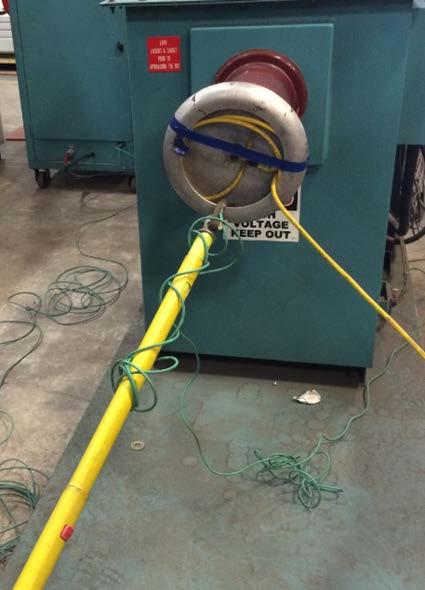
28 Safety precautions during electrical inspection Define the boundaries that prohibit unauthorized personnel from entering the restricted area.


29 Safety precautions during electrical inspection Use warning lights on the test equipment to warn area personnel of presence of voltage on the equipment.

30 Safety precautions during electrical inspection Limit the use of high voltage as much as possible. Ensure that all high voltage test leads are color coded and readily identifiable. A phase is black, B phase is red and C phase is yellow.
31 Safety precautions during electrical inspection Special precautions should be observed with following: Device Potential Danger Required Action Circuit Breakers Stored Energy Make sure springs are discharged & contacts are open before attempting any service. Current Transformers Capacitor Trip Device Shock Hazard & Equipment Damage Shock Hazard & Electrical Burns Do not open secondary of any CT under load. Before disconnecting any CT leads, remove power source or short the secondary at shorting type TB. Removing the device cover automatically discharges some cap trip devices. Shorting output with resistor can also be used to discharge cap trip device.
32 Safety precautions during electrical inspection Customer Inspection Safety:
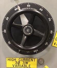
33 Safety precautions during electrical inspection Conclusion: Familiarize yourself with manufacturing facility & equipment under test. Only the authorized personnel is responsible for the handling of the power handle. Read manufacturer's instruction bulletin prior to any testing. Do not look for shortcuts. Do not put yourself in a position where you feel your safety has been compromised.


34 Equipment Internal Inspection Objective: To thoroughly inspect the equipment utilizing internal checklists and procedures to ensure that the equipment have been properly designed and constructed to meet the specifications.
35 Equipment Internal Inspection Process Flow

36 Equipment Internal Inspection Equipment Line History Checklist:

37 Equipment Internal Inspection Equipment Line History Checklist:

38 Equipment Internal Inspection Equipment Line History Checklist:

39 Equipment Internal Inspection Check for correct TB/Device arrangement.

40 Equipment Internal Inspection Check that all terminal block/devices have been labeled.

41 Equipment Internal Inspection.Check that TB markings are legible.
 against master")
42 Equipment Internal Inspection Check auxiliary relay contact configuration (NO or NC) against master drawings.

43 Equipment Internal Inspection Check that correct fuses or links have been installed. Check that the TOC has been installed and adjusted.

44 Equipment Internal Inspection Check that MOC has been installed and adjusted.
45 Equipment Internal Inspection Check that CT wiring has been buzzed to shunt block.

46 Equipment Internal Inspection Check that all CT shorting terminal block shunt screws have been installed.

47 Equipment Internal Inspection Buzz all PT, CPT, & DC wiring to fuse blocks or circuit breakers.
48 Equipment Internal Inspection Check that equipment is in compliance with the Master Copy specification print.

49 Equipment Internal Inspection Check Bill of Material against equipment and master drawings

50 Equipment Internal Inspection Check that key interlocks have been installed and adjusted.
51 Equipment Internal Inspection Check that each key interlock assembly and the entire key interlock system operates correctly.

52 Equipment Internal Inspection Check that all device mounting and terminal screws have been tightened..

53 Equipment Internal Inspection Check for correct crimping and tightness of all lug terminations.

54 Equipment Internal Inspection Check that doors have been installed and adjusted. Check that nameplates have been installed in accordance with Master Copy print. Check all interconnect wiring against Master Copy print.

55 Equipment Internal Inspection Check that door-bonding jumper has been installed.

56 Equipment Internal Inspection Check that all CT s have been installed with polarity correct and wired in accordance with Master Copy wiring print.

57 Equipment Internal Inspection For bus mounted CTs, verify that resin filled CTs are installed for 95kV BIL applications.

58 Equipment Internal Inspection Wire tags checked against Master Copy wiring print. Check that all wire/metal jumpers have been installed in accordance with Master Copy wiring print.

59 Equipment Internal Inspection Check that low voltage wiring is isolated from high voltage by metal.

60 Equipment Internal Inspection Check that mimic bus has been installed per Master Copy print.
61 Equipment Internal Inspection Review meeting minutes to see if all the project requirements are captured. For example: Check primaries of VTs are connected through hard copper bus. Check bus joints have boots and not tape. Check ring lugs are provided for current circuits. Check Origination-Destination type wiring is used Check test switch contacts connected in trip circuit has red handles. Check that all relays have conformal coating.
62 Equipment Internal Inspection Final Inspection/Testing of the equipment: Visual Inspection Bussing Check Mechanical Tests CT Inspection UPS System Tests AC/DC Circuit Breaker Panel Tests Primary Injection Test High Voltage Test High Potential Test SS Automation Tests CAUTION: BEFORE ENERGIZING EQUIPMENT REVIEW "SAFETY PROCEDURES FOR ELECTRICAL INSPECTION AND GENERAL TESTING PRECAUTIONS AND CHECKS.
63 Final Inspection/Testing of the equipment: Type of Test Visual Inspection Purpose To verify base, layout, elevation, and door detail dimensions against Master Copy Drawings. To verify all Material per Master Copy Drawings. To ensure nameplates installed matches the Master Copy Drawings. What to check? Measure all equipment dimensions per the drawings and highlight the acceptable dimensions in yellow. Check all components against the Bill of Material. Investigate any differences in catalog numbers & material shortage. Check all nameplates against the nameplate schedule. Investigate any differences in nameplates and/or spelling with the schedule.
64 Final Inspection/Testing of the equipment: Type of Test Bussing Check Purpose To ensure that the bussing of the equipment matches the drawings and is built to the standards. What to check? Check the three-line and sectional view drawings against the switchgear bus work. Check all bus clearances. Check that bus dimensions and phasing will line up to transformer or mating equipment drawings. Check that ground bus connections have been made between units and to mating equipment.

65 Final Inspection/Testing of the equipment:
66 Final Inspection/Testing of the equipment: Type of Test Purpose What to check? Mechanical Tests To ensure the proper functioning of all the mechanical aspects of the equipment. Check all shutters, mechanical interlocks, racking mechanism, cell switches (mechanism and truck operated), and door interlocks for proper operation. Check all doors, locks, doorstops, mechanical interlocks, overhead lift devices, and louvers for proper operation. Check all key interlock systems (if applicable). Verify the interchangeability of all draw out or removable elements of the same rating. And those elements of a lower rating shall not be interchangeable with a higher rating element.
67 Final Inspection/Testing of the equipment: Type of Test CT Inspection Purpose To verify all relays, meters, and devices in the circuits operate as required by the three-line diagrams and schematics. What to check? Ensure that all circuits are verified; highlight each circuit with yellow marker as they are verified. Functional check the equipment per applicable control scheme and threeline diagrams. Perform circuit continuity check on any equipment, which cannot be functionally operated.
68 Final Inspection/Testing of the equipment: Type of Test Control Tests Purpose To verify all relays, meters, and devices in the circuits operate as required by the three-line diagrams and schematics. What to check? Ensure that all circuits are verified; highlight each circuit with yellow marker as they are verified. Functional check the equipment per applicable control scheme and threeline diagrams. Perform circuit continuity check on any equipment, which cannot be functionally operated.

69 Final Inspection/Testing of the equipment:
70 Final Inspection/Testing of the equipment: Primary Injection Test: Purpose: To verify instrument transformers circuits, ratio and ensure correct operations of primary disconnecting device. Checks: Ensure that potential transformers and control power transformers mounted in rollouts have their primary fuses removed. Check bus work is clean and free from all debris. Check all current transformer polarity marks for proper orientation against the relay bulletin and three-line diagram. Verify all relay and current transformer connections with a buzzer before energizing circuit.
 with a bolted")

71 Final Inspection/Testing of the equipment: Primary Injection Test: Process: Connect current leads of test cart to incoming bus (observe phasing) with a bolted ring-tongue-lug arrangement. Connections should be tight to prevent arcing. Short the bus on the unit to be tested with a braided copper strap and turn current & control power on.
72 Final Inspection/Testing of the equipment: Primary Injection Test: Process (cont d): Apply secondary potential on PT circuits to check all power type meters and relays. Verify CT ratio & polarity by varying the current and voltage to check that the test equipment readings match the equipment in test. Verify relay operations by varying current from the test cart and adjusting settings of protective relays to see if relay is picked up which will either trip the breaker or drop out the contactor. Ensure that all circuits are verified; highlight each circuit with yellow marker as they are verified.

73 Final Inspection/Testing of the equipment: Primary Injection Test:
74 Final Inspection/Testing of the equipment: High Potential Test: Purpose: Hi-Pot testing is performed to demonstrate the ability of the insulation system to withstand the voltages in accordance with ANSI C37.09, IEEE C , IEEE C , ANSI/IEEE C , ANSI/IEEE C37.23, IEEE C57.13 and NEMA Standards Publication No. ICS 1 & 3. Checks: Check bus work is clean and free from all debris. Check that all bus boots have been installed. Check that clearances are within the limits per IEEE C
75 Final Inspection/Testing of the equipment: High Potential Test: Checks (cont d): Potential transformers and control power transformers mounted in rollouts must have their primary fuses removed and the rollout or tilt-out compartment inserted for the test. Check that wiring on rollout and in rollout compartment has been secured properly. Before applying test voltage, disconnect all glow tubes, lightning arresters, power factor correction capacitors, and surge capacitors.
76 Final Inspection/Testing of the equipment: High Potential Test: Process: Primary Hi-Pot tests are performed at the specified voltage listed in the relevant product s ANSI/IEEE standard s tables for voltage and rated insulation levels. Table 1 - DC EQUIPMENT BUS WORK HI-POT VALUES Equipment Type DC Bus Duct Insulation Level (kv) Operating Voltage Rated Frequency Withstand DC Withstand 300/ DC LV Switchgear 300/
77 Final Inspection/Testing of the equipment: Equipment Type Table 2 - AC EQUIPMENT BUS WORK HI-POT VALUES Max Operating voltage (kv) Rated Frequency withstand Insulation Level (kv) DC Withstand Switchboards Nonsegregated-Phase Bus LV MCC Metal-Enclosed LV Switchgear E2 Controllers Metal-Clad Switchgear Metal-Enclosed Interrupter Switchgear See IEEE C , Table 1, note b. See IEEE C , Table 1, note b
78 Final Inspection/Testing of the equipment: High Potential Test: Process (cont d): With primary switching device in the connected position and closed, apply specified voltage (per tables) between each phase with other phases grounded. The High-Pot is a pass-fail test. Pass shall be that after reaching the specified test voltage the equipment will maintain that voltage for one minute. At the conclusion of the test, the voltage should be decreased slowly to the minimum obtainable before the circuit is opened. After the test has been completed, all circuit breakers and disconnecting switches must be opened and the high-potential cable grounded.


79 Final Inspection/Testing of the equipment: High Potential Test:


80 Final Inspection/Testing of the equipment: High Potential Test:
81 Final Inspection/Testing of the equipment: High Voltage Test: Purpose: High voltage or system voltage testing is performed to run the primary system voltage on the equipment to energize potential transformers, control power transformers and to check out the associated secondary equipment in a situation as near to field conditions as possible.
82 Final Inspection/Testing of the equipment: High Voltage Test: Checks: Check all mechanical bus connections on roll-outs and tilt-outs and verify primary and secondary phasing with a buzzer. Place primary fuses back to potential transformers and control power transformers mounted in rollouts. Insert rollout/tilt-out compartment back in for the test. Connect ground wires on test cart to equipment under test and to building column ground. Ensure no other foreign voltages are present.
83 Final Inspection/Testing of the equipment: High Voltage Test: Process: Connect high voltage leads of HVTC to incoming bus (observe phasing) with a bolted ring-tongue-lug arrangement. Connections should be tight to prevent arcing. Test all components according to circuit requirements and highlight the prints with yellow marker as the circuits are completed. Once high voltage testing is complete deenergize the bus by switching off the circuit breaker on the HVTC control panel. Check bus work with voltage detector before disconnecting the high voltage leads. Secure the HVTC high voltage leads and the color coded power cable.

84 Final Inspection/Testing of the equipment: Substation Automation: Substation automation testing are generally divided in two parts: Factory Acceptance Tests (FATs): To verify communication architecture for all the equipment inside substations, IED configuration & management, testing activities related to ECMS etc. Site Acceptance Tests (SATs): This involves detailed testing for each electrical piece of equipment that is connected to overall plant automation system either via hardwired interface or over a communication interface.


 protection elements, transformer differential elements (87U,87Rand 87Q) etc.")
85 Final Inspection/Testing of the equipment: Substation Automation: IED configuration & management If relay settings are provided then also perform relay control & protective function check. Use secondary injection test for generating the secondary voltages and currents to check instantaneous overcurrent elements(ioc), time overcurrent elements(toc), bus differential (87B) protection elements, transformer differential elements (87U,87Rand 87Q) etc. Perform dynamic simulation of autotransfer scheme for secondary selective systems per customer specifications.
86 Final Inspection/Testing of the equipment: Substation Automation: Verify communication architecture Ensure that all the communication cables are wired correctly between all IEDs, energy meters, Ethernet switches, communication processors etc. Verify all IRIG-B interconnections for precise time recording for all IEDs through satellite clock. Check all the IEDs, meters and other substation equipment like UPS, battery charger etc are communicating over the specified protocol (Modbus, DNP3, IEC etc)


87 Final Inspection/Testing of the equipment: Substation Automation: If substation has electrical control & management system (ECMS), Verify that all analog and discrete data from all the IEDs is transferred over correct protocol. Verify that system is able to perform remote switchgear operations, generator management, sequence of events, executing load shed/restoration controls etc per customer requirement. Conduct static simulation of HMI during the process & check all analog and discrete data points that need to be displayed on HMI. Ensure that HMI screens have all the relevant one-lines, all associated IED detail screens, remote control of MCCs/VFDs etc per customer specifications.
88 Final Inspection/Testing of the equipment: Other Substation Equipment s Tests: Type of Test UPS system tests What to check? Check system out per manufacturer s bulletin. Check functional operations for transfer and check all alarms and output contacts. Check for full charging of batteries before shutdown of system. Check panel breakers and/or fuses for correct size and rating. Before shipment, check that the batteries are charged and disconnected. AC & DC circuit breaker panel tests Check all wires with buzzer to assure correct destination per drawings. Check for correct voltage and phase rotation per drawings on line side of main breaker. Check each feeder breaker one at a time to check that circuit works per Master Copy print. Check each feeder breaker one at time with clamp-on ammeter to see that load current is per breaker size. Battery Chargers Check that battery chargers source breaker (LV MCC or panel breaker) current rating is correct per manufacturer s bulletin Connect battery circuit of equipment under test to battery test cart with test cart charging system off. Check for charging current on battery charger ammeter. Check battery charger for alarms and troubleshoot system per Master Copy Prints and battery charger bulletin. Check all alarms against PLC and/or annunciator. Turn off the charger by de-energizing all DC loads and restart again. Annunciators Annunciator systems are tested at the vendor s factory and they are generally tested for the interconnection to the associated equipment to be monitored during substation FAT. Verify that description and location of all annunciator windows is per the drawings. Start individual window testing and check that windows light up and alarm sounds. Depress Silence button, horn will stop alarming but light will stay in blinking mode. Depress Acknowledge button and all window lights will stop blinking.
VACUUM BREAKER MEDIUM VOLTAGE AUTOMATIC TRANSFER SWITCHES
 Part One General 1.01 Scope A. It is the intent of this specification to provide a medium voltage automatic transfer system. B. All components, testing and services specified and required for a complete
SECTION AUTOMATIC TRANSFER SWITCHES
 PART 1 - GENERAL 1.1 DESCRIPTION SECTION 26 36 23 SPEC WRITER NOTE: Use this section only for NCA projects. Delete between //--// if not applicable to project. Also, delete any other item or paragraph
CONTENTS AUTOMATIC TRANSFER SWITCHES
 CONTENTS AUTOMATIC TRANSFER SWITCHES PART 1 GENERAL 1.1 Related Documents 1.2 Summary 1.3 References 1.4 Quality Assurance 1.5 Submittals 1.6 Delivery, Storage and Handling 1.7 Instructions And Training
SECTION P01 LIGHTING AND APPLIANCE PANELBOARDS - A-SERIES
 PART 1 GENERAL A. The requirements of the Contract, Division 1, and Division 16 apply to work in this Section. 1.01 SECTION INCLUDES A. Lighting and appliance panelboards 1.02 RELATED SECTIONS A. 16475,
SECTION AUTOMATIC TRANSFER SWITCHES PART 1 - GENERAL
 SECTION 16400 AUTOMATIC TRANSFER SWITCHES 1.01 RELATED DOCUMENTS PART 1 - GENERAL A. Drawings and general provisions of Contract, including General Conditions and Division 1 Specification sections, apply
EG Controls. SLIMVIEW 120 VOLT FLOAT SERIES DUPLEX PUMP CONTROL PANEL SPECIFICATION for CITY OF E G
 E SLIMVIEW 120 VOLT FLOAT SERIES DUPLEX PUMP CONTROL PANEL SPECIFICATION for CITY OF DATE: 11/13/06 2/1/07 1 Copyright, E, Inc. E 1. ENERAL...4 1.1 Scope Of Work... 4 1.2 Codes and Standards... 4 2. PRODUCTS...5
Powerohm Resistors Digital HRG System
 Installation and Operating Instructions Powerohm Resistors Digital HRG System This manual provides general information, installation, operation, maintenance, and system setup information for the Powerohm
A. Section includes distribution panelboards and lighting and appliance branch-circuit panelboards.
 SECTION 262416 - PANELBOARDS PART 1 - GENERAL 1.1 SUMMARY A. Section includes distribution panelboards and lighting and appliance branch-circuit panelboards. 1.2 PERFORMANCE REQUIREMENTS A. Seismic Performance:
SECTION AUTOMATIC TRANSFER SWITCHES
 PART 1 - GENERAL 1.1 DESCRIPTION SECTION 26 36 23 This section specifies the furnishing, complete installation, and connection of automatic transfer switches. 1.2 RELATED WORK A. Section 14 21 00, ELECTRIC
Student Services & Classroom Addition. A. Section includes distribution panelboards and lighting and appliance branch-circuit panelboards.
 SECTION 262416 - PANELBOARDS PART 1 - GENERAL 1.1 SUMMARY A. Section includes distribution panelboards and lighting and appliance branch-circuit panelboards. 1.2 PERFORMANCE REQUIREMENTS A. Seismic Performance:
TRANSMISSION ENGINEERING STANDARDS SUBSTATIONS
 This standard was reviewed and approved by key managers with final approval by an officer of Oncor Electric Delivery on. 1.0 SCOPE 1.1 This guide applies to the interconnection of a Customer with the Company
PANELBOARDS & BUILDING DISTRIBUTION
 262416 PANELBOARDS & BUILDING DISTRIBUTION PART 1 GENERAL 1.01 SUMMARY A. Section Includes: 1. Distribution panelboards 2. Power panelboards B. Related Sections: 1.02 POLICY 1. CU Standard 260500, Basic
SUGGESTED SPECIFICATION For Series 300 Manual Transfer Switches (3MTS)
") SUGGESTED SPECIFICATION For Series 300 Manual Transfer Switches (3MTS) PART 1 GENERAL 1.01 Scope Furnish and install manual transfer switches (3MTS) with number of poles, amperage, voltage, and withstand
SUGGESTED SPECIFICATION For Series 300 Manual Transfer Switches (3MTS) PART 1 GENERAL 1.01 Scope Furnish and install manual transfer switches (3MTS) with number of poles, amperage, voltage, and withstand
SECTION ENCLOSED CONTROLLERS
 PART 1 - GENERAL 1.1 RELATED DOCUMENTS A. Drawings and general provisions of the Contract, including General and Supplementary Conditions, apply to this Section. 1.2 SUMMARY A. This Section includes ac,
MASTER JOCKEY PUMP CONTROLLER. Model JPCE INSTRUCTION MANUAL. C 2018 Master Control Systems, Inc
 MASTER JOCKEY PUMP CONTROLLER Model JPCE INSTRUCTION MANUAL C 2018 Master Control Systems, Inc TABLE OF CONTENTS Important Safety Information. Page 3 General Description and Installation.. Page 4 Model
Brown University Revised June 29, 2012 Facilities Design & Construction Standards SECTION ELECTRICAL DESIGN CRITERIA
 PART 1 - GENERAL 1.1 Background SECTION 26 00 10- ELECTRICAL DESIGN CRITERIA A. Brown University maintains it own campus electrical distribution system which serves the majority of the buildings and facilities
Revision: None DCN No. First Issue Date: November 30, 1998 Product: Standard DCT, 120-volts
 Figure 1Document: SPEC-112 Revision: None DCN No. First Issue Date: November 30, 1998 Product: Standard DCT, 120-volts construction requirements of UL approved Class H (180 C) insulation system. Transformers
1S25. Arc Fault Monitor 4 Zones, 8 Sensors. Features. Introduction. ARC Fault Protection
 Technical Bulletin Arc Fault Monitor 4 Zones, 8 Sensors Features Four independent arc fault tripping zones 1 or 2 arc fault sensors per zone allowing up to 8 arc fault sensors per module Trip indication
Guide Specification Model CTG Automatic Transfer Switch
 Guide Specification Model CTG Automatic Transfer Switch PART 1 GENERAL 1.1 Scope A. It is the intent of this specification to secure a transfer switch that has been prototype tested, factory built, production
DC POWER DISTRIBUTION BOARD
 DC POWER DISTRIBUTION BOARD February 2016 Engineering Department WEST BENGAL STATE ELECTRICITY TRANSMISSION COMPANY LIMITED Regd. Office: VidyutBhawan, Block DJ, Sector-II, Bidhannagar, Kolkata 700091.
C. ASME Compliance: Fabricate and label water chiller heat exchangers to comply with ASME Boiler and Pressure Vessel Code: Section VIII, Division 1.
 SECTION 236426 - ROTARY-SCREW WATER CHILLERS PART 1 - GENERAL 1.1 SUMMARY A. This Section includes packaged, water cooled or air cooled as scheduled, electric-motor-driven, rotary-screw water chillers
Installation Instructions
 Electric Heaters 5 --- 20 kw SMALL PACKAGED PRODUCTS (SPP) Accessory Electric Heaters For 13 SEER, R---410A, Z Chassis Installation Instructions NOTE: Read the entire instruction manual before starting
.4 Do complete installation in accordance with latest Electrical Bulletins of the local inspection authority.
 Fitness Facility Addition Page 1 1.1 CODES AND STANDARDS.1 Do complete installation in accordance with the latest edition of the CSA C22.1 as amended by the latest editions of the National Building Code
CENTERLINE 2100 Motor Control Center (MCC) Doors and Units with Vertical Operating Handles
 Doors and Units with Vertical Operating Handles") Installation Instructions Original Instructions CENTERLINE 2100 Motor Control Center (MCC) Doors and Units with Vertical Operating Handles Bulletin Number 2100 Topic Page About This Publication 1 Important
Installation Instructions Original Instructions CENTERLINE 2100 Motor Control Center (MCC) Doors and Units with Vertical Operating Handles Bulletin Number 2100 Topic Page About This Publication 1 Important
NORTHWESTERN UNIVERSITY PROJECT NAME JOB # ISSUED: 11/06/2018
 SECTION 26 2913 - ENCLOSED CONTROLLERS GENERAL 1.1 RELATED DOCUMENTS A. Drawings and general provisions of the Contract, including General and Supplementary Conditions and Division 01 Specification Sections,
MASTER PRESSRE MAINTANENCE CONTROLLER. Models PMCE INSTRUCTION MANUAL. C 2018 Master Control Systems, Inc
 MASTER PRESSRE MAINTANENCE CONTROLLER Models PMCE INSTRUCTION MANUAL C 2018 Master Control Systems, Inc TABLE OF CONTENTS Important Safety Information. Page 3 General Description and Installation.. Page
NATIONAL ELECTRICAL CODE (NEC) & NFPA 70E ARC FLASH ELECTRICAL SAFETY
 & NFPA 70E ARC FLASH ELECTRICAL SAFETY") A new twist on the National Electrical Code - a practical application workshop. If you sign up in this class, prepare to work! Day 1: Fundamentals of OSHA requirements for performing electrical work -
A new twist on the National Electrical Code - a practical application workshop. If you sign up in this class, prepare to work! Day 1: Fundamentals of OSHA requirements for performing electrical work -
NFPA 70E Arc Flash Considerations for MV Equipment. By: Dominik Pieniazek, P.E. HV Engineering, LLC
 NFPA 70E Arc Flash Considerations for MV Equipment By: Dominik Pieniazek, P.E. dominik@hv-eng.com HV Engineering, LLC http://sites.ieee.org/houston/ Full link for PDF copies of presentations: http://sites.ieee.org/houston/communities/ie
Introduction Consultant shall incorporate the material in the DSS into the project specifications.
 DIVISION 16 - ELECTRICAL Section 16000 - General Discussion Introduction Consultant shall incorporate the material in the DSS into the project specifications. Refer any questions, clarifications regarding
SECTION DOMESTIC WATER PRESSURE BOOSTING SYSTEMS (VFD) PART 1 - GENERAL 1.1 SUMMARY
 PART 1 - GENERAL 1.1 SUMMARY") SECTION 22 11 23.13 DOMESTIC WATER PRESSURE BOOSTING PART 1 - GENERAL 1.1 SUMMARY A. Where utility water pressure cannot adequately meet the pressure requirements of the domestic water systems and where
SECTION 22 11 23.13 DOMESTIC WATER PRESSURE BOOSTING PART 1 - GENERAL 1.1 SUMMARY A. Where utility water pressure cannot adequately meet the pressure requirements of the domestic water systems and where
SECTION AUTOMATIC TRANSFER SWITCHES
 SECTION 26 36 23 AUTOMATIC TRANSFER SWITCHES PART 1 - GENERAL 1.1 RELATED DOCUMENTS A. General provisions of the Contract, including General and Supplementary Conditions and Division 01 Specification Sections,
VeriSafe Absence of Voltage Tester The safe way to verify the absence of voltage
 VeriSafe Absence of Voltage Tester The safe way to verify the absence of voltage www.panduit.com/verisafe What is an Absence of Voltage Tester? Absence of Voltage Testers (AVTs) are permanently-mounted
Reliable solutions for electrified railway systems
 Reliable solutions for electrified railway systems 1 2 3 Insulation Enhancement System Insulation Enhancement System 1. Raychem MVLC: (Medium Voltage Line Cover) Provides insulation for catenary, droppers
Development of standards for MV Switchgear for Arc Flash protection. ABB Group May 20, 2013 Slide 1
 Development of standards for MV Switchgear for Arc Flash protection May 20, 2013 Slide 1 Development of standards for MV Switchgear for Arc Flash protection Bryan Johnson ABB South Africa Shaping the world
UFGS (November 2008) UNIFIED FACILITIES GUIDE SPECIFICATIONS
 UNIFIED FACILITIES GUIDE SPECIFICATIONS") USACE / NAVFAC / AFCESA / NASA UFGS-26 28 21.00 40 (August 2008) ----------------------------------- Preparing Activity: NASA Superseding UFGS-26 28 21.00 40 (November 2008) UNIFIED FACILITIES GUIDE SPECIFICATIONS
USACE / NAVFAC / AFCESA / NASA UFGS-26 28 21.00 40 (August 2008) ----------------------------------- Preparing Activity: NASA Superseding UFGS-26 28 21.00 40 (November 2008) UNIFIED FACILITIES GUIDE SPECIFICATIONS
Installation Instructions
 50ES--A, 50EZ--A, 50VG--A, B, 50VL--A, B, 50VR--A, 50VT--A, B 604D-- --A, 607C-- --A, B, 607E-- --A, 704D-- --A, 707C-- --A, B, 707E-- --A PA3G -- -- A, PH3G -- -- A, PA4G, PH4G PAD3, PHD3, PAD4, PHD4,
Instruction Manual HWR MODEL RESISTO-FLO ELECTRIC BOILER
 Page 1 of 16 Instruction Manual HWR MODEL RESISTO-FLO ELECTRIC BOILER Page 2 of 16 FOREWORD The HWR Resisto-Flo Electric Hot Water Boiler is designed to provide a compact packaged unit requiring a minimum
SPECIFICATIONS FOR ELECTRICAL INSTALLATIONS
 Attachment PUC 4-8-5 Page 1 of 26 SUPPLEMENT TO SPECIFICATIONS FOR ELECTRICAL INSTALLATIONS PRIMARY METER POLE ELECTRIC SYSTEM BULLETIN No. 753 JUNE 1993, 2ND PRINTING APRIL 2002 (Supersedes issue dated
TRANSMISSION ENGINEERING STANDARDS SUBSTATIONS
 This standard was reviewed and approved by key managers on September 6, 2011. Officer approval of this revision is not required. 1.0 SCOPE 1.1 This guide applies to the interconnection of a Utility with
INSTALLATION, OPERATING & MAINTENANCE INSTRUCTIONS FOR 350 SERIES CIRCULATION HEATERS
 INDEECO Circulation Heaters are designed to provide years of trouble free operation if properly installed and maintained. Please read and follow these instructions for installing and maintaining the heater.
Installation Instructions
 50ZPB, C, 50ZHB, C, PA3Z ---A, PH3Z ---A, PA4Z, PH4Z, PAJ4,PHJ4,WJA4,WJH4 SMALL PACKAGED PRODUCTS (SPP) Accessory Electric Heaters 5---20 kw For 14 SEER, R---410A Manufactured Home Installation Instructions
Installation Instructions
 Electric Heaters 5 --- 20 kw SMALL PACKAGED PRODUCTS (SPP) Accessory Electric Heaters For 13 SEER, R---410A Manufactured Home Installation Instructions NOTE: The Dual Point Kit can only be installed on
PURCHASING SECTION th Street, Surrey, B.C. V3S 3C7 Tel: Fax: ADDENDUM NO.
 PURCHASING SECTION 6645 148 th Street, Surrey, B.C. V3S 3C7 Tel: 604-590-7274 Fax: 604-599-0956 E-mail: purchasing@surrey.ca ADDENDUM NO. 2 REQUEST FOR QUOTATIONS (RFQ) NO.: 1220-040-2014-001 TITLE: DISTRICT
SECTION GENERATOR PARALLELING CONTROLS
 PART 1 - GENERAL 1.1 DESCRIPTION SECTION 26 23 13 GENERATOR PARALLELING CONTROLS SPEC WRITER NOTE: Delete between // -- // if not applicable to project. Also delete any other item or paragraph not applicable
A. This Section includes transfer switches rated 600 V and less, including the following:
 SECTION 16415 - TRANSFER SWITCHES PART 1 - GENERAL 1.1 RELATED DOCUMENTS A. Drawings and general provisions of the Contract, including General and Supplementary Conditions and Division 1 Specification
Installation Instructions
 50ES---A, 50EZ---A, 50VL---A, 50VG---A, 50VR---A, 50VT---A, 604D--- ---A, 607C--- ---A, 607E,--- ---A, 704D--- ---A, 707C--- ---A, 707E--- ---A PA3G --- --- A, PH3G --- --- A SMALL PACKAGED PRODUCTS Electric
ELECTRICAL CURRICULA OUTLINE CORE CURRICULUM 2015
 ELECTRICAL CURRICULA OUTLINE CORE CURRICULUM 2015 Basic Safety (Construction Site Safety Orientation) (12.5 Hours) (Module ID 00101-15) Presents basic jobsite safety information to prepare workers for
How to reduce exposure to arc flash hazards
 GE Electrical Distribution How to reduce exposure to arc flash hazards Multiple solutions for new and existing facilities imagination at work Multiple Issues Today s power system engineer must not only
SECTION LOW VOLTAGE POWER PANELBOARDS - SPECTRA
 PART 1 GENERAL A. The requirements of the Contract, Division 1, and Division 16 apply to work in this Section. 1.01 SECTION INCLUDES A. Low voltage power panelboards 1.02 RELATED SECTIONS 1.03 REFERENCES
Pump Station Operator Training Checklist
 Pump Station Operator Training Checklist Operator Training Checklist The following outlines the Operator training required upon successful Start-Up of every Rain Bird Pump Station. The Authorized Service
Element D Services Electrical
 PART 1 - GENERAL 1.01 OVERVIEW A. This Section includes design standards and requirements for electrical service and distribution. This is a design standard and is not intended to be used as a Specification.
MANUAL INSTALLATION. Fan Column. v200 Issue Date: 01/18/ Price Industries Limited. All rights reserved.
 MANUAL INSTALLATION Fan Column v200 Issue Date: 01/18/17 2017 Price Industries Limited. All rights reserved. TABLE OF CONTENTS Product Overview General Safety Information...1 Safety Notices...1 Unit Description...2
PART GENERAL 1.01 SECTION INCLUDES
 Specification Number: 26 24 16.06 Product Name: Emergency Lighting Control NQ Circuit Panelboards: 240 Vac, 48 Vdc Maximum SECTION 26 24 16.06 Emergency Lighting Control NQ Circuit Panelboards: 240 Vac,
The safe way to verify the absence of voltage.
 VeriSafe Absence of Voltage Tester The safe way to verify the absence of voltage www.panduit.com/verisafe What is an Absence of Voltage Tester? Absence of Voltage Testers (AVTs) are permanently-mounted
SECTION DIGITAL, ADDRESSABLE FIRE-ALARM SYSTEM
 SECTION 283111 - DIGITAL, ADDRESSABLE FIRE-ALARM SYSTEM PART 1 - GENERAL 1.1 RELATED DOCUMENTS A. Drawings and general provisions of the Contract, including General and Supplementary Conditions and Division
Inspection and Test Plan for Switchgear
 Inspection and Test Plan for Switchgear No. Inspection and Test Plan Reference Document Acceptance Criteria Verifying Document Activity By Remark Manuf. TPI Client 1 Pre Inspection Meeting Spec. Spec.
38-SDMS-04 REV. 0 SPECIFICATION FOR ANNUNCIATOR SYSTEMS FOR PRIMARY DISTRIBUTION SUBSTATION
 38-SDMS-04 REV. 0 SPECIFICATION FOR ANNUNCIATOR SYSTEMS FOR PRIMARY DISTRIBUTION SUBSTATION This specification is property of SEC and subject to change or modification without any notice. TABLE OF CONTENTS
MODEL YVAA EQUIPMENT PRE-STARTUP AND STARTUP CHECKLIST CUSTOMER: LOCATION: ADDRESS: CUSTOMER ORDER NO: PHONE: JCI CONTRACT NO: JOB NAME:
 Supersedes: 201.28-CL2 (817) Form 201.28-CL2 (1017) MODEL YVAA EQUIPMENT PRE-STARTUP AND STARTUP CHECKLIST CUSTOMER: LOCATION: ADDRESS: PHONE: JOB NAME: CUSTOMER ORDER NO: JCI CONTRACT NO: CHILLER MODEL
PUMP CONTROL CENTER (PCC)
") PART 1 SUMMARY A. In accordance with the plans and specifications, the Contractor shall provide and install a complete pre-fabricated, pre-tested ArcSafe Pump Control Center including all required equipment,
PART 1 SUMMARY A. In accordance with the plans and specifications, the Contractor shall provide and install a complete pre-fabricated, pre-tested ArcSafe Pump Control Center including all required equipment,
Predictive Maintenance Training
 Predictive Maintenance Training Contact us Today for a FREE quotation to deliver this course at your company?s location. https://www.electricityforum.com/onsite-training-rfq This predictive maintenance
1. Floor above/floor below notification. 2. Private alarm notification. 3. Not Used 4. Voice alarm notification. 5. Not Used.
 PART 1 GENERAL 1.01 Scope of Standard A. This Standard is intended to assure that fire alarm and signaling systems at Sam Houston State University provide the highest level of life safety possible. This
T22 - Arc Flash Hazards and Arc Resistant Equipment- Understanding the Standards
 T22 - Arc Flash Hazards and Arc Resistant Equipment- Understanding the Standards v2-5058-co900h Copyright 2016 Rockwell Automation, Inc. All Rights Reserved. 1 Agenda 1. Background 2. Related Electrical
Battery Fail Monitoring System
 Battery Fail Monitoring System Table of Contents 1 DOCUMENTATION 1.1 Introduction 2 GENERAL INFORMATION 2.1 Scope of the Manual 2.2 Product Description 3 DESCRIPTION OF FEATURES, ALARMS AND CONTROLS 3.1
PIP PCTPA001 Testing of Process Analyzer Systems
 January 2016 Process Control PIP PCTPA001 Testing of Process Analyzer Systems PURPOSE AND USE OF PROCESS INDUSTRY PRACTICES In an effort to minimize the cost of process industry facilities, this Practice
SUMMARY: Policy Title: Electrical Safety Work Practice Program. Policy Number: UNIV-EHS 430 Policy Approved: January 2014
 Policy Title: Electrical Safety Work Practice Program Policy Number: UNIV-EHS 430 Policy Approved: January 2014 Policies Superseded: FINA-730 Policy Management Area: Environmental Health and Safety Created/Revision(s):
EQUIPMENT PRE-STARTUP AND STARTUP CHECKLIST TEL NO: ORDER NO: CONTRACT NO:
 Supersedes: (316) Form QTC4-CL2 (617) MODEL QTC4 EQUIPMENT PRE-STARTUP AND STARTUP CHECKLIST CUSTOMER: ADDRESS: PHONE: JOB NAME: LOCATION: CUSTOMER ORDER NO: TEL NO: ORDER NO: CONTRACT NO: CHILLER MODEL
SECTION AUTOMATIC TRANSFER SWITCH
 SECTION 26 36 23 AUTOMATIC TRANSFER SWITCH PART 1 - GENERAL 1.1 SUMMARY A. Furnish and install automatic transfer switch (ATS) with number of poles, amperage, voltage and withstand current ratings as shown
Property risk solutions
 Property risk solutions Inside this issue Welcome to this edition of the Property risk solutions newsletter. This quarterly publication focuses on fixed fire protection and human element safety solutions
FIREFLY II PLUS RELEASE DEVICES INSTALLATION MANUAL
 FIREFLY II PLUS RELEASE DEVICES INSTALLATION MANUAL MADE IN THE U.S.A. U.L. LISTED CANADIAN LISTED CSFM: 7300-1418:100 GENERAL DESCRIPTION SERIAL NUMBER The Cookson Company FIREFLY II PLUS Time Delay Release
9/7/2010. Chapter , The McGraw-Hill Companies, Inc. AND BONDING. 2010, The McGraw-Hill Companies, Inc.
 Chapter 1 GROUNDING AND BONDING 1 Proper grounding practices protect people from the hazards of electric shock and ensure the correct operation of overcurrent protection devices. Grounding is the intentional
www. ElectricalPartManuals. com GADP Ground Fault Indication System Instruction Manual Ground Fault Protection
 Ground Fault Protection GADP Ground Fault Indication System Instruction Manual 7615 Kimbel Street, Mississauga, Ontario Canada L5S 1A8 Tel: (905)673-1553 Fax: (905)673-8472 Toll Free: 1-888-RESISTR 737-4787
TABLE OF CONTENTS CHAPTER 1 GENERAL RULES CHAPTER 2 WIRING AND PROTECTION... 51
 TABLE OF CONTENTS About This Textbook...xi How to Use the National Electrical Code... 1 Article 90 Introduction to the National Electrical Code... 7 90.1 Purpose of the NEC... 7 90.2 Scope of the NEC...
SEL Arc-Flash Solutions
 SEL Arc-Flash Solutions Arc-Flash Protection at the Speed of Light Protect personnel and equipment Detect arc-flash events and send a trip signal in as little as 2 ms to enhance safety and minimize equipment
power Describe the purpose of lockout/tag-out devices Demonstrate use of lockout/tagout
 c. All contestants are required to remain in the contest area until the contest has been torn down and excused by the Chairperson. Note: Your contest may also require a hard copy of your résumé as part
Electrical Design Guidelines Table of Contents
 C: Compliant Rev. 3 Dated June 13 11 NC: Non-Compliant NA: Not Applicable Page1 16.1 General 16.2 Single Line Diagrams 16.3 Electric Motor Equipment and Controls 16.4 Lighting 16.5 Emergency Lighting 16.6
Public Safety DAS Annunciator Panel
 Public Safety DAS Annunciator Panel 120 VAC Models: 1221-A, 1221-B, 1221-C Revision D 91117 48 VDC Models: 1221-A-48, 1221-B-48, 1221-C-48 24 VDC Models: 1221A-24, 1221-B-24, 1221-C-24 CAUTION: (Read This
Safety Function: Single-beam Area Access Control (AAC)
") Application Technique Safety Function: Single-beam Area Access Control (AAC) Products: Guardmaster Dual-input Safety Relay, Single-beam Area Access Control Sensors with E-stop Safety Rating: CAT. 4, PLe
Application Technique Safety Function: Single-beam Area Access Control (AAC) Products: Guardmaster Dual-input Safety Relay, Single-beam Area Access Control Sensors with E-stop Safety Rating: CAT. 4, PLe
THE "SS90" SERIES RELEASE DEVICES MODEL B2 INSTALLATION MANUAL
 S S S S S S S S 90 OLID TATE ECURITIES, INC SOLID STATE FAIL-SAFE UNIT * PATENT PENDING LISTED U 99Y9 RESET L RELEASING DEVICE SOLID STATE SECURITIES, INC. THE "SS90" SERIES RELEASE DEVICES MADE IN THE
IEEE Transformer Committee PC Distribution Transformer Monitoring - User
 IEEE Transformer Committee PC57.167 Distribution Transformer Monitoring - User Mark Scarborough Electrical Engineering Consultant DuPont January 9, 2019 Transformer Types in DuPont Control power Dry-type
UHIR Series. Horizontal or Vertical Mounting Industrial / Commercial Electric Unit Heater. Owner s Manual
 UHIR Series Horizontal or Vertical Mounting Industrial / Commercial Electric Unit Heater Owner s Manual This manual covers installation, maintenance and repair parts. Read carefully before attempting to
Installation Instructions
 EHNA Electric Heaters 5-20kW For 60 Hz Small Packaged Products MODELS: PAD3, PHD3, PAD4, PHD4, PAD5, PHD5, WPA3, WPH3 Installation Instructions NOTE: Read the entire instruction manual before starting
TAG MR VOLTAGE DETECTORS AND ACCESSORIES. Instruction & Operation Manual
 TAG 200 200MR 2000 330 VOLTAGE DETECTORS AND ACCESSORIES Instruction & Operation Manual TAG-200, TAG-200MR and TAG-2000 (Distribution Voltages) and TAG-330 (Transmission Voltages) units are shown with
Basin Heater. user manual INSTALLATION OPERATION MAINTENANCE
 user manual Basin Heater INSTALLATION OPERATION MAINTENANCE Z0238873_A ISSUED 03/2017 READ AND UNDERSTAND THIS MANUAL PRIOR TO OPERATING OR SERVICING THIS PRODUCT. receiving and inspection The heater
R E C T I F I E R I N V E R T E R C O N V E R T E R SB7
 SCR Battery Charger Product Specifications Description The is RIC Electronics premiere SCR battery charger/rectifier. The provides power to critical DC loads through a wide range of outputs and is engineered
Installation and Operating Instructions ISH ELECTRIC STEAM SUPERHEATER
 Installation and Operating Instructions ISH ELECTRIC STEAM SUPERHEATER 1 Installation and Operating Instructions ISH ELECTRIC STEAM SUPERHEATER FOR YOUR SAFETY This manual supplies information on the application,
SECTION LIGHTING CONTROLS
 PART 1 - GENERAL 1.1 DESCRIPTION SECTION 26 09 23 LIGHTING CONTROLS SPEC WRITER NOTE: 1. Delete between //----// if not applicable to project. Also, delete any other item or paragraph not applicable to
Quartzone. Infrared Quartz Tube & Metal Sheathed Electric Heaters. Owner s Manual. File E COMFORT HEATERS for INDOOR* and OUTDOOR** USE
 Quartzone Infrared Quartz Tube & Metal Sheathed Electric Heaters Owner s Manual File E97759 COMFORT S for INDOOR* and OUTDOOR** USE *Excluding Residences ** With Quartz Elements and when mounted Underneath
STATEWIDE CAREER/TECHNICAL EDUCATION COURSE ARTICULATION REVIEW MINUTES
 STATEWIDE CAREER/TECHNICAL EDUCATION COURSE ARTICULATION REVIEW MINUTES Articulation Agreement Identifier: ELT 118 (2005-1) Identifier is the postsecondary course prefix followed by Plan-of-Instruction
Arc Flash Analysis: IEEE Method versus the NFPA 70E Tables July 2017 / 1910DB1702
 Arc Flash Analysis: IEEE Method versus the NFPA 70E Tables July 2017 / 1910DB1702 by Reza Tajali, Schneider Electric Engineering Services Summary 1.0 Abstract 2.0 OSHA and NFPA Rules 3.0 Use of NFPA 70E
MODEL B2 INSTALLATION MANUAL
 RELEASE DEVICES GENERAL DESCRIPTION MODEL B2 INSTALLATION MANUAL S/N: The B2 Series Time Delay Release Devices are UL Listed, Canadian Listed, and CSFM Listed for use on rolling doors, single-slide and
USER S MANUAL AND INSTALLATION INSTRUCTIONS IMPORTANT
 USER S MANUAL AND INSTALLATION INSTRUCTIONS P3BD Series 13 SEER Single Package Air Conditioner IMPORTANT Read this owner information to become familiar with the capabilities and use of your appliance.
IN-7750 April Instruction Manual. Ventilated Dry-Type Transformers. Unit Substation Type and Other Transformers Above 600 Volts
 Instruction Manual IN-7750 April 2017 Ventilated Dry-Type Transformers Unit Substation Type and Other Transformers Above 600 Volts Instructions for the Safe Handling, Installation, Operation and Maintenance
Emerson Blue Easy Set 1H/1C
 Emerson Blue Easy Set 1H/1C Model: 1F86EZ-0251 Non-Programmable Thermostat with 3 Temperature Pre-Sets Home, Sleep and Away Installation Instructions and User Guide Message to Homeowner Congratulations
Security CCTV System Construction Checklist
 Security CCTV System Construction Checklist Project: Building: Location: Submittal / Approvals Submittal. The above equipment and systems integral to them are complete and ready for functional testing.
Tempco s process controllers provide integrated solutions to manage your thermal loop system.
 5 Control Panels Managing 5 Circulation Heating Systems Application: Cleaning and applying chromate coating to aircraft parts Tempco s process controllers provide integrated solutions to manage your thermal
Models NFPA 1221-A, NFPA 1221-B Public Safety DAS Annunciator Panel. Revision E 61117
 Models NFPA 1221-A, NFPA 1221-B Public Safety DAS Annunciator Panel Revision E 61117 CAUTION: (Read This First) This panel has been designed to make it nearly bullet proof to mistakes made when wiring
NORTHWESTERN UNIVERSITY PROJECT NAME JOB # ISSUED: 03/29/2017
 SECTION 26 3323 - CENTRAL BATTERY EQUIPMENT [for Evanston campus only] PART 1 - GENERAL 1.1 RELATED DOCUMENTS A. Drawings and general provisions of the Contract, including General and Supplementary Conditions
1.1 DESCRIPTION A. The purpose of this section is to specify Division 23 responsibilities in the commissioning (Cx) process.
 process.") SECTION 239950 MECHANICAL COMMISSIONING SYSTEMS PART 1 - GENERAL 1.1 DESCRIPTION A. The purpose of this section is to specify Division 23 responsibilities in the commissioning (Cx) process. B. Commissioning
SECTION 239950 MECHANICAL COMMISSIONING SYSTEMS PART 1 - GENERAL 1.1 DESCRIPTION A. The purpose of this section is to specify Division 23 responsibilities in the commissioning (Cx) process. B. Commissioning
Cautions and Warnings. Introduction 4009 NAC POWER EXTENDER
 Cautions and Warnings DO NOT INSTALL ANY SIMPLEX PRODUCT THAT APPEARS DAMAGED. Upon unpacking your Simplex product, inspect the contents of the carton for shipping damage. If damage is apparent, immediately
Changes to NFPA 70E. - The Role of PdM &Safe PdM Work Practices. Tim Rohrer Exiscan LLC
 Changes to NFPA 70E - The Role of PdM &Safe PdM Work Practices Tim Rohrer Exiscan LLC Tim@Exiscan.com 585-705-7775 Joe Gierlach ABM Joseph.Gierlach@ABM.com 412-394-4678 Preview Electrical Safety Risk Management