SAFI250 Machine Safety. Introduction
|
|
|
- Katrina Floyd
- 6 years ago
- Views:
Transcription
1 SAFI250 Machine Safety Introduction
2 Course Objectives Participant will: Explain safety categories Define SIL and PL Identify safety opportunities Discuss product options Setup basic operation of products
3 Module objectives At the end of this module the participant will: Explain the risk management aspects of machine safety Define the role of the standards used for applying machine safety

4 White paper Unfamiliarity with Standards, Device Integration Tops List of Machine Safety System Concerns for Machine Builders by Dave Collins Over 3000 people responsible for machine safety


5 66% anticipate using more safety products 55.8% not aware of safety categories 68% not aware of PL 61% did not know they needed to meet SIL

6 Safety Market Survey

7 Processes and Machines Linking functional islands and machines Machine/Process Safety Inputs and outputs signal processing Emergency stop by control Disconnection of power supply Initialization and control of hazardous movements Restricted access to hazardous zones Disconnection of power supply
8 Standards and architecture
9 Module objectives At the end of this module the participant will: Define the standards involved with machine safety Define terms associated with the standards specifically Safety Integrity Level (SIL) and Performance Level (PL) Explain methods to determine appropriate SIL and PL Outline the process for determining PL
10 Managing risk Residual risk Tolerable risk EUC risk Necessary risk reduction Increasing risk Actual risk reduction Practical risk covered by other technology safety-related systems Practical risk covered by E/E/PE safety-related systems Practical risk covered by external risk reduction facilities Risk reduction achieved by all safety-related systems and external risk reduction facilities
11 Functional Safety Sector specific standards for Process Industry and Machines Safety of Systems and Equipment IEC Functional safety of electrical / electronic / programmable electronic safety-related systems EN Safety related parts of control systems Process Machines Software IEC IEC IEC EN/ISO Standards highlighted in red are International standards
12 IEC Seven part standard for complex subsystems (e.g. products) and systems SIL Systems/devices can be classified as two types Safety of Systems and Equipment IEC Functional safety of electrical / electronic / programmable electronic safety-related systems Process Software Machines EN Safety related parts of control systems IEC IEC IEC EN/ISO Low complexity or simple systems: Failure modes are 100% known Complex All failure modes not known Complex equipment must comply with IEC and is responsibility of the component manufacturer.
13 EN Safety of Systems and Equipment IEC Functional safety of electrical / electronic / programmable electronic safety-related systems EN Safety related parts of control systems Process Machines Software IEC IEC IEC EN/ISO Defines Categories Sets method or architecture to accomplish goal More subjective
14 Standards relating to IEC Safety of Systems and Equipment IEC Functional safety of electrical / electronic / programmable electronic safety-related systems EN Safety related parts of control systems Process Machines Software IEC IEC IEC EN/ISO IEC 61511: Functional safety - Safety instrumented systems for the process industry IEC : Functional safety of electrical/electronic/programmable electronic safety-related systems - Software IEC 62061: Machine Safety Safety Integrity Levels (SIL)
15 EN/ISO Safety of Systems and Equipment IEC Functional safety of electrical / electronic / programmable electronic safety-related systems EN Safety related parts of control systems Process Machines Software IEC IEC IEC EN/ISO Specify requirements and implementation for safetyrelated control systems Defines Performance Levels PFHd (Probablility of dangerous Failure per Hour)
16 Which Standard Should be Used? Safety of Systems and Equipment IEC Functional safety of electrical / electronic / programmable electronic safety-related systems Process Machines EN Safety related parts of control systems Software IEC IEC IEC EN/ISO IEC (SIL) Simple to Complex systems Electrical/electronic/programmable electronic safety systems EN/ISO (PL) Simple to low complexity Electrical, mechanical, pneumatic and hydraulic safety-related systems Machine designers can choose either or both.
17 Evolution of improvement Categories (EN954-1) Safety Integrity Levels - SIL Performance Levels - PL
18 EN Categories S F Severity of injury S1 - Slight (normally reversible injury) S2 - Serious (normally irreversible) injury including death Frequency and/or exposure time to the hazard F1 - Seldom to less often and/or the exposure time is short F2 - Frequent to continuous and/or the exposure time is long P Possibility of avoiding the hazard or limiting the harm P1 - Possible under specific conditions P2 - Virtually impossible
 A single fault must not cause the loss of the safety function.")

19 EN954-1: Risk Assessment Safety Category B Control System Requirements Control per basic specifications Use of well tried and tested components and principles Safety functions shall be checked at suitable intervals (frequency to be determined to application) A single fault must not cause the loss of the safety function. The single fault shall be detected when ever reasonably practical. A single fault must not cause loss of safety function. This fault be detected at or before the next demand shall of the safety function. An accumulation of faults must not cause loss of safety function. Control System Behavior (in the event of a fault) Possible loss of safety function Greater reliability but possible loss of safety function Fault detected at each test Safety function ensured except in the case o an accumulation or faults. Safety function always ensured, an accumulation of faults is not possible.

20 Examples of products by Category Use of basic control components Use of well tried and tested components and principles Periodically tested Redundancy Redundancy + continuous self checking B
21 Evolution of improvement Categories Safety Integrity Levels SIL (IEC and IEC 62061) Performance Levels PL
22 Safety Standards IEC Electrical / Electronic / Programmable Systems Functional Safety Passive protection Total life cycle of system\ IEC Simpler more functional
23 Categories (per EN954-1) S F Severity of injury S1 - Slight (normally reversible injury) S2 - Serious (normally irreversible) injury including death Frequency and/or exposure time to the hazard F1 - Seldom to less often and/or the exposure time is short F2 - Frequent to continuous and/or the exposure time is long P Possibility of avoiding the hazard or limiting the harm P1 - Possible under specific conditions P2 - Virtually impossible
24 Safety Integrity Level per IEC Class of Probability of Harm (CL) CL = Fr + Pr + AV Fr = Frequency of Exposure Pr = Probability of Occurrence AV= Probability of Avoiding harm Se = Severity of Injury
25 Safety Integrity Level Consequences Death, loosing an eye or arm Permanent, loosing fingers Reversible, medical attention Reversible, first aid G ey a ea Sa ety esu es eco e ded Severity Class Cl (Se) SIL 2 SIL 2 SIL 2 SIL 3 SIL 3 3 OM SIL 1 SIL 2 SIL 3 2 OM SIL 1 SIL 2 1 OM SIL 1
26 Safety of Machinery and Functional Safety Machinery: Determination of the required SIL. (Example according to IEC/EN 62061) Consequences Severity (Se) Irreversible: death, losing an eye or arm 4 Irreversible: broken limb(s), losing a finger(s) 3 Reversible: requiring attention from a medical practitioner 2 Reversible: requiring first aid 1 Frequency and duration of exposure (Fr) Frequency of exposure Duration > 10 min <= 1 h 5 > 1 h to <= 1 day 5 > 1 day to <= 2 weeks 4 > 2 weeks to <= 1 year 3 > 1 year 2 Probability of occurrence Probability (Pr) Very high 5 Likely 4 Possible 3 Rarely 2 Negligible 1 Serial no. Hazard Se Fr Pr Av Cl 1 hazard x = 12 2 Probability of avoiding or limiting harm (Av) Impossible 5 Rarely 3 Probable 1 Consequences Death, loosing an eye or arm Permanent, loosing fingers Reversible, medical attention Reversible, first aid G ey a ea Sa ety esu es eco e ded Severity Class Cl (Se) SIL 2 SIL 2 SIL 2 SIL 3 SIL 3 3 OM SIL 1 SIL 2 SIL 3 2 OM SIL 1 SIL 2 1 OM SIL 1
27 Safety of Machinery and Functional Safety Machinery: Risk assessment form (given as an example in IEC 62061) Risk assessment and safety measures Product: Issued by: Date: Consequences Death, losing an eye or arm Permanent, losing fingers Reversible, medical attention Reversible, first aid Black area = Safetymeasures required Grey area = Safety mesures recommended Severity Class Cl Frequency and duration Probability of hzd. Event Avoidance (Se) Fr Pr Av 4 SIL 2 SIL 2 SIL 2 SIL 3 SIL 3 <= 1 hour 5 Common 5 3 OM SIL 1 SIL 2 SIL 3 > 1 h to <= 1 day 5 Likely 4 2 OM SIL 1 SIL 2 > 1 day to <= 2 wks 4 Possible 3 Impossible 5 1 OM SIL 1 > 2 wks to <= 1 year 3 Rarely 2 Possible 3 > 1 year 2 Negligible 1 Likely 1 No. Hazard Se Fr Pr Av Cl Safety Measure Safe Comments
28 Safety Integrity Level Probability of a Hazardous Failure per hour (PFH d ) Average probability of a dangerous failure per hour PFHd SIL IEC 61508, EN >= 10-5 to < 10-4 No special safety requirements >= 3 x 10⁻⁶ to < >= 10-6 to < 3 x >= 10-7 to < >= 10-8 to <
29 Safety Integrity Level High Demand on Machine Safety System SIL to < 10-7 (per chart in ISO/EN ) 10-7 PFHd < 10-8 (mathematically) Between and Dangerous failures per HOUR
30 SIL 4 Yes, it exists but don t worry about it UNLESS the results of failure leaves a crater!
31 Evolution of improvement Categories Safety Integrity Levels - SIL Performance Levels PL (EN/ISO )
32 Performance Level (PL) EN/ISO Required performance level (PL r ) Low contribution to risk reduction S1 S2 F1 F2 F1 F2 P1 P2 P1 P2 P1 P2 P1 P2 a b c d e Safety-related system High contribution to risk reduction
33 Performance Levels Probability of Dangerous Failure per Hour Performance level EN/ISO PL Average probability of a dangerous failure per hour PFHd SIL IEC 61508, EN a >= 10-5 to < 10-4 No special safety requirements b >= 3 x 10⁻⁶ to < c >= 10-6 to < 3 x d >= 10-7 to < e >= 10-8 to <
34 Category Architecture Behavior B i m i m Input Logic Output i m i m Input Logic Output i m i m Input Logic Output i Test m Test equipment output m i m Input 1 Logic 1 i m Output 1 cross monitoring m i m Input 2 Logic 2 i m Output 2 m i m Input 1 Logic 1 i m Output 1 cross monitoring m i m Input 2 Logic 2 i m Output 2 Fault can lead to loss of safety function Fault can lead to loss of safety function but high MTFFd reduces chance of function loss Fault can lead to loss of safety function between checks; check detects loss of safety function Fault does not lead to loss of safety function, detect single fault before next demand of safety function Fault does not lead to loss of safety function, detect fault before next demand (switch off at end of next operating cycle)
35 Performance Levels Safety Related Parts of Control System (SRP/CS) Identifies the parts and pieces in the system Terms introduced for PL Mean Time To Dangerous Failure (MTTFd) Diagnostic Coverage (DC) Common Cause Failures (CCF)
36 Performance Levels Mean Time to dangerous Failure (MTTFd) Denotation of mean time to dangerous failure Low Medium High Range of MTTFd 3 years MTTFd < 10 years 10 years MTTFd < 30 years 30 years MTTFd < 100 years
37 Performance Levels Diagnostic Coverage Denotation of diagnostic coverage Range None DC < 60% Low 60% DC < 90% Medium 90% DC< 99% High 99% DC
38 Performance Levels Common Cause Failure Fuse Relay Device Relay Fuse
39 Performance Levels Risk assessment Determine Required PL (Performance Level) Determine Architecture Evaluate PL Verify PL Validate
40 Performance Levels Risk assessment Determine Required PL Determine Architecture Evaluate PL Verify PL Validate S1 S2 F1 F2 F1 F2 P1 P2 P1 P2 P1 P2 P1 P2 Required performance level (PL r ) a b c d e Low contribution to risk reduction High contribution to risk reduction
41 Performance Levels Risk assessment Determine Required PL Determine Architecture Evaluate PL Verify PL Validate S1 S2 F1 F2 F1 F2 P1 P2 P1 P2 P1 P2 P1 P2 Required Low contribution performance to risk reduction level (PL r ) a b c d e High contribution to risk reduction
42 Performance Levels Risk assessment Determine Required PL I1 I2 L1 L2 O1 O Determine Architecture Evaluate PL Verify PL INPUT Interlocking Switch 1 SW1 (XCS) Interlocking Switch 2 SW2 (XCS) SRP/CS a LOGIC Safety Relay SR1 (XPS) SRP/CS b OUTPUT Contactor 1 CON1 Contactor 2 CON2 SRP/CS c 6. Validate
43 Performance Levels Risk assessment Determine Required PL Determine Architecture Evaluate PL Verify PL Validate Consult Table K1 of the standard Category or Structure MTTFd of all components DC (Diagnostic Coverage) CCF (Common Cause Failure) DC avg 1 MTTF = d DC1 MTTF 1 MTTF d1 d1 = ~ N i = 1 DC2 + MTTF 1 + MTTF 1 MTTF d2 d di DCN MTTF 1 MTTF dn dn
44 Performance Levels Risk assessment Determine Required PL Determine Architecture Evaluate PL Verify PL Validate Performance level a * b 1 c 1 d 2 e 3 Cat. B DC avg = 0 Cat. 1 DC avg = 0 * Cat. 2 DC avg = low Cat. 2 DC avg = medium Cat. 3 DC avg = low Cat. 3 DC avg = medium DC = Diagnostic Coverage MTTF d = Mean Time To Failure - Dangerous PL = Performance Level Cat. 4 DC avg = high Safety Integrity Level

45 Performance Levels Risk assessment Determine Required PL Determine Architecture Evaluate PL Verify PL Validate User documents the: Procedure used Assumption list Calculations Refer to ISO
46 Performance Levels Risk assessment Determine Required PL Determine Architecture Evaluate PL Verify PL Validate Questions?

47 SISTEMA Safety Integrity Software Tool for the Evaluation of Machine Applications From IFA: Institut für Arbeitsschutz der Deutschen Gesetzlichen Unfallversicherung Helps calculate the PL Free download User must understand how to do calculations manually Schneider Electric makes no recommendations regarding the use of this tool. Website:
48 Other considerations and terms
49 Module objectives At the end of this module the participant will Define terms specific to contact configurations used in machine safety circuit Explain operating modes for machine safety components Define access time in terms of machine safety

50 Contact terms Slow make and break Speed of contact action dependent on speed of operator 9001 KA1 for example

51 Contact terms Snap Action Action of contacts not fully dependent on motion of operator Contacts move to pretravel position then continue action

52 Contact terms
53 Operating modes Negative mode relies on device to open contacts properly Hazard potential


54 Operating modes Positive mode forces switch to open contacts Hazard potential If only one switch, must be positive mode.
55 Operating modes Best practice: combine modes
56 Contact terms Positive Opening Contacts will open period. EN and NFPA 79

57 Contact terms Mechanically linked Link between contacts Min. distance between contacts in case of weld

58 Contact terms Linked Contacts a.k.a. mechanical guided, forced guided NC contact welds, impossible to close NO contacts (energized coil) If NO contacts welds, impossible to open NC contact (de-energized coil)
59 Contact terms Mirrored contacts NC aux contact linked to NO power poles Never closed at same time as power poles If power pole welds, link prevents NC aux contact from closing when de-energized TeSys D and TeSys K meet this requirement!

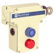
60 Access time Access time of personnel vs. the stopping time of the machine Hazard Stopping time is less than access time: guard does not need to be locked Hazard Stopping time is greater than access time: guard must be locked until the hazard poses no threat 63 inches per second for movement of hand


61 Access time Machinery with instant stopping (Stopping time < access time) Standard non-locking safety interlock switches or locking switches
 Interlocking with actuating key Use solenoid locking safety interlocks.")
62 Access time High inertia machines; Long stopping time (Stopping time > access time) Interlocking with actuating key Use solenoid locking safety interlocks.
63 Why know these terms? An e-stop would require what type of contact? Monitoring for welded contacts requires what? To insure that two sets of contacts never close at the same time we d use what? To monitor for welded power contacts use
64 Terms - Stop Categories In addition to Safety Categories (per ISO ), there are categories that identify the stopping characteristics of the machine or process. Do not get these confused with Safety Categories. Three categories of emergency stop function: Category 0: Immediate removal of power (all machines must have a category 0 or 1 emergency stop) Category 1: Power to machine actuators to achieve the stop, then the removal of power (all machines must have a Category 0 or 1 emergency stop) Category 2: Power to machine actuators to achieve the stop; power remains on the circuit These stop categories are identified in EN and NFPA 79

65 Machine Safety Products
66 Module objectives At the end of this module the participant will Identify various components associated with machine safety Define operating platforms available Locate specific catalog items from the machine safety catalog Perform basic set of E-stop with monitoring Safety interlock schemes with gate protection


67 Machine Safety Solutions E-Stop Inputs Guarding & Positioning Machine Safety Products Logic Output
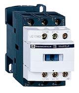
68 Machine Safety Related Contactors and relays Only certain ones Based on category levels (not SIL or PL) Catalog page: 6/22 E-Stop push buttons Required per other applications and codes Catalog page: 7/9 Limit Switches, Cable Pull, Palm Switches Be aware of other products related to machine safety
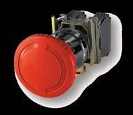
69 E-stop specifics Visible and readily accessible Red actuator with Yellow background Initiated by single human action Continuously operable, clearly indentified
 Reset will not restart machine")
70 E-stop specifics Absolute priority over all other functions Capability at each work station, location Category 0 or 1 must have e-stop NOT flat panel Mechanical latch (pull or rotate to release) Reset will not restart machine
71 Machine Safety Products Safety interlocks With and without locking With locking solenoid Lever arm and rotary Non-contact Control platforms Relays Controllers PLCs Light curtains
72 Safety Interlocks Limit access to areas while machine operates Stops machine when guards are opened Monitored to prevent starting machine


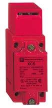
73 XCSA, XCSB and XCSC Catalog pg: 3/24 Metal body Unlocking means Without locking - XCSA Tubular key - XCSC Pushbutton - XCSB Location of key or pushbutton easily changed from left to right side of switch Easy to rotate non-removable head Actuating key approach from top or side
 Locking with power Rotatable non-removable head IP67 Actuating key approach from")
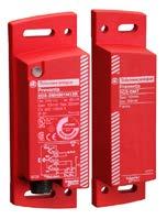
74 XCSE Catalog pg: 3/25 Rugged metal switch with locking solenoid Locking without power (preferred) Locking with power Rotatable non-removable head IP67 Actuating key approach from top or side
75 XSCLE / XCSLF Slim profile Plastic (E) or metal (F) Locking with solenoid Locking without power (preferred) Locking with power Rotatable head


76 XCSMP Safety Interlock Switch Catalog pg: 3/40 Miniature safety interlock - only 0.6 wide 2 directions of actuation, top and side 3 types of actuating keys IP67 Pre-cabled, several lengths

77 Non-Locking Safety Interlock Catalog pg: 3/44 Used where stopping time is less than access time XCSPA - slim plastic body XCSTA - wide plastic body Easy to rotate non-removable head Actuating key approach from top or side IP67
 Locking with power Easy to rotate nonremovable")
78 XCSTE Catalog pg: 3/45 Compact plastic switch with locking solenoid Locking without power (preferred) Locking with power Easy to rotate nonremovable head

79 Lever Type Safety Interlocks Catalog pg: 3/52 Two lever types available XCSPL - slim plastic body XCSTL - wide plastic body Used on hinged doors or guards Head can be rotated in 4 directions Easy to rotate non-removable head No actuating key to align or attach to the guard, eliminating alignment issues Straight or offset levers
80 Rotary Shaft Interlock Catalog pg: 3/52 Two rotary types available XCSPR - slim plastic body XCSTR - wide plastic body Used on hinged doors or guards Head can be rotated in 4 directions No actuating key to align or attach to the guard Can be used on narrow doors or guards
81 Rotary Shaft Interlock Shaft fits over hinge pin and is secured to the hinge pin When the door is opened, switch operates When the shaft is operated 5, switch contacts change state Available in two shaft lengths: Standard: 1.18 (30mm) Extended: 3.15 (80mm)
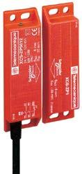
82 Non Contact Interlocks Catalog pg: 3/56 XCSDMR XCSDMP XCSDMC

83 Non Contact Interlocks Suitable for Category 4 XCSDMP Face to face, side to side and face to side actuation* With or without LED indicator XCSDMC Face to face, side to side and face to side actuation. With or without LED indicator XCSDMP XCSDMC

84 Non Contact Interlocks XCSDMR Face to face, side to side actuation. With or without LED indicator XCSDMR


85 Machine Safety Platforms Type Safety Relay Safety Controller Safety PLC AS-I Safety Card Family XPS XPSMC XPSMF ASISAFE Lexium 32 Function Solution for monitoring one function Solution for monitoring several functions simultaneously Solution for monitoring many functions simultaneously and communication over Safe Ethernet Solutions using a safety related communications bus Solutions using a motion controller Schneider Electric Preventa Machine Safety Products 86

86 Safety Relays Monitor status of guards and interlocks Prevent and stop machine operation Won t allow machine start until conditions are met
87 Safety Relays, How Do They Work? L1 (+) F1 (+) S1 ( ) K3 K4 A1 S11 S12 S21 S22 B1 Y1 Y V 230 V T + XPS K1 Logic K1 K2 K2 K3 K3 K3 K3 A2 PE S33 S K4 K4 K4 K4 S2 Start K3 K4 N ( ) Schneider Electric Preventa Machine Safety Products 88
88 Safety Relays, How Do They Work? L1 (+) F1 (+) S1 ( ) K3 K4 Safety Outputs: A1 S11 S12 S21 S22 B1 Y1 Y V 230 V T + XPS K1 Logic K1 K2 A2 PE S33 S K2 Aux K3 K3 K4 K4 Power K3 K3 K4 K4 N ( ) S2 Start K3 K4 K3 & K4 are external relays/contactors Schneider Electric Preventa Machine Safety Products 89
89 Safety Relays, How Do They Work? L1 (+) F1 (+) S1 ( ) K3 K4 Safety Outputs: A1 S11 S12 S21 S22 B1 Y1 Y V 230 V T + XPS K1 Logic K1 K2 A2 PE S33 S K2 Aux K3 K3 K4 K4 Power K3 K3 K4 K4 N ( ) S2 Start K3 K4 K3 & K4 are external relays/contactors Schneider Electric Preventa Machine Safety Products 90
90 Safety Relays, How Do They Work? L1 (+) F1 (+) S1 ( ) K3 K4 Safety Outputs: A1 S11 S12 S21 S22 B1 Y1 Y V 230 V T + XPS K1 Logic K1 K2 A2 PE S33 S K2 Aux K3 K3 K4 K4 Power K3 K3 K4 K4 N ( ) S2 Start K3 K4 K3 & K4 are external relays/contactors Schneider Electric Preventa Machine Safety Products 91

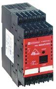
91 XPSAF and XPSAFL Catalog pg: 2/187 & 2/191 For E- stop and switch monitoring Removable and non-removable terminals 22.5mm wide 3 N.O. safety outputs 3 LED s for easier set-up and troubleshooting 24V AC/DC XPS-AF Category 4 E-stop, interlock switches XPS-AFL Category 3 with e-stop and interlock switches Designed for Type 4 light curtain inputs for category 4
92 XPSAK Catalog pg: 2/201 For emergency stop and interlock switch monitoring Removable and non-removable terminals Category 4 45mm wide 3 N.O. safety outputs 1 N.C. auxiliary output 4 S.S. outputs for PLC signaling 4 LED s for set-up and troubleshooting Dual voltage devices available - 120VAC & 24 VDC, 230V AC & 24 VDC, as well as 24VAC/DC
93 XPSBF Catalog pg: 2/209 For Two Hand Control Applications Removable and non-removable terminals Category mm wide 2 N.O. safety outputs. 2 S.S. outputs for PLC signaling 3 LED s for set-up and troubleshooting 24V DC


94 Safety Controller XPSMCWIN XPS MC16Z XPS MC16ZC XPS MC16ZP XPS MC32Z XPS MC32ZC XPS MC32ZP
 with solid state and relay outputs with muting Magnetic non-contact safety interlocks Two-hand control device (EN 574:Type IIIC) Safety mat Zero speed detection Injection moulding")
95 Solutions inside firmware Emergency stop with single and dual channel buttons Guard with single or dual channel and with interlock Light curtains (type 4) with solid state and relay outputs Light curtains (type 4) with solid state and relay outputs with muting Magnetic non-contact safety interlocks Two-hand control device (EN 574:Type IIIC) Safety mat Zero speed detection Injection moulding machine Hydraulic press valve monitoring (3 valves) Eccentric press control with optional valve monitoring (XPS-PVK/OT) Seat valve monitoring (1 valve) Enabling device OR logic Timing functions Optional stop cat.0 and stop cat.1 for all outputs Plus many more


96 Machine Safety Controller XPSMCWIN Drag and Drop interface Part of Safety Suite Certified Safety Functions

97 Machine Safety Controller Diagnostic Window Yellow arrow = error message Green = ON state Red = OFF state Text message in bottom yellow frame Grey = not used
98 Machine Safety Controller PLC Modbus CANopen Profibus

99 AS-Interface Safety at Work Catalog pg: 2/262

100 AS-Interface Safety at Work PLC and standard ASi master AS-i power supply Standard interface Safety monitor Emergency - stop pushbutton with safety interface Safety light curtain Standard Interface Safety monitor Safety interlock switch with attached safety interface
101 AS-Interface Safety at Work ASISAFEMON1B 1 output group ASISAFEMON2B 2 output groups
102 AS-Interface Safety at Work Monitors devices Emergency stop buttons Safety guards Light curtains Logic functions OR (up to 6 devices) On delay/off delay/pulse, etc EDM


103 AS-Interface Safety at Work Interfaces for emergency stop buttons M16 thread M12 connectors IDC (Vampire pin)


104 Safety PLC s Catalog pg: 2/4 XPSMF safety PLCs

105 Safety PLC s XPSMF Safety PLCs SafeEthernet Distributed Safety I/O SIL 3 per IEC PL e per ISO
106 LAB EXERCISES
107 Light curtains
108 Module objectives At the end of this module the participant will Determine when to use safety interlocks vs light curtains Explain various terms associated specifically with light curtains Perform basic set up of light curtains Select components necessary to meet light curtain applications
109 Safety Interlocks vs. Light Curtains Safety Interlocks where: Access not desired or needs to be limited Large areas or multiple points of access Flying debris, fluids or coolants, or other materials to keep away from personnel Lower cost is a primary concern Light Curtains where: Easy physical access to hazardous areas Clear visibility of the operation is desired Gates and guards may not be practical Cannot be used where potential for flying debris exists
110 Requirements for use Must be able to stop anywhere in its cycle. Must not present a hazard from flying parts or debris Must have consistent response and stopping times Satisfy all governmental and local rules, codes, and regulations including (but not limited to) ANSI and OSHA Responsibility of user and/or employer Severe smoke, particulate matter, and corrosives may degrade the efficiency of a light curtain Additional guarding may be required


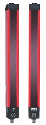
111 Light Curtains - XUSL Where gates or guards are impractical or undesired Excellent visibility of the machine or process Provides free access to work area Point of operation or perimeter guarding Floating blanking and fixed blanking functions Will not protect operators or personnel from flying projectiles or debris
112 Specialized terms Minimum Object Sensitivity (MOS) Minimum Safety Distance Blanking Floating Exact Muting Alignment system Type 2 and Type 4 curtains
113 Minimum Object Sensitivity Affects minimum safety distance Smallest diameter of object sensed Finger protection: 14 mm Hand protection: 30 mm
114 Minimum Safety Distance (Ds) Based on movement of 63 in/sec for hand Depends on which entity OSHA ANSI CE Calculate all and largest separation distance
115 Blanking & Muting Any blanking increases the MOS and minimum safety distance Floating: allows a specific number which floats (entry location varies) Exact channel: fixed group to allow for machine parts (supports, fixtures) Muting: temporary time to allow passing of material (not hands)
116 Alignment system Individual Blocked Beam Indicators illuminate whenever a beam is not detected by the receiver A A Beam Indicator A Receiver Channel

117 Blocked Beam Indicators (BBI) Illuminate whenever a beam is not detected by the receiver, Illuminate if exact channel select blanked beam is detected when it should be blocked. One for each light beam in the light curtain. Aid in installation, adjustment and troubleshooting C Standard on all Schneider Electric Light Curtains BBI LED s B A Infrared Receivers
118 Floating Blanking The synchronizing beam must always be present and cannot be floated. One or two beams can be blocked without opening light curtain outputs Typical applications: Sheet metal Conveyors Paper
119 Exact channel blanking An object programmed to be in the field must remain in the field for the light curtain to operate Beams blanked are inverse (light curtain looks for dark) Typical applications Brackets Conveyors The synchronizing beam must always be present and cannot be blocked

120 Muting Beams temporarily ignore missing signals while material in field for specific time The synchronizing beam must always be present and cannot be blocked Temporary suspension of beams as material moves in or out time sensitive Typical applications Assembly Conveyor
121 Type 2 vs Type 4 light curtains Type 2 Perimeter guard Periodic self-checking (power up and reset) Type 4 Point of operation (serious injury) Pinch points, areas where shearing or punching Continuous self-checking
122 Type 2 applications Packaging Conveyors Warehouse/storage Robot areas
123 Type 4 applications Presses, shears, trimmers Hoisting equipment Saws Machine and wood working Textiles
124 Two and three box configurations Two box Emitter Transmitter No control box required Three box Emitter Transmitter Control box Early design of curtains Fading usage
125 Light curtains catalog
126 How to Select the Right Light Curtain 1 - What light curtain type is required? 2 - What is the MOS? 3 - What is the protected height? 4 - Is blanking going to be used? 5 - Is customer aware of the proper use of minimum safety distance formulas?

127 The Product Range Type 4 Type Compact Compact Compact Compact Family XUSLB XUSLD XUSLPZ XUSLPB MOS 14 mm and 30 mm 0.55 in and 1.18 in 14 mm and 30 mm 0.55 in and 1.18 in 300, 400,500,600 mm 11.8, 15.7, 19.7, 23.6 in. 500 and 600 mm 19.7 and 23.6 in Sensing Distance SN 1 to 22.9 ft, or 1 to 65.6 ft with PDM 1 to 22.9 ft, or 1 to 65.6 ft with PDM 2.6 to 65.5 ft or 2.6 to ft 2.6 to 26.3 ft
128 The Product Range Type 2 Type Single Beam Compact Family XPSCM and XU2S XUSLN XPSCM XU2S XU2S MOS Single Beam 30 mm, 1.18 in Sensing Distance SN 26.2 ft 0.89 to ft
129 XUSLB Light Curtain pg 3/92 Optimum range Manual and auto start External Device Monitoring by wiring or terminal, MTS (test) Sensing distance: 22.9 ft (7m) (Φ14mm) 26.2 or 65.6 ft (8m or 20m) (Φ30mm) 14 mm and 30 mm (0.55 and 1.18 in) MOS

 Sensing")
* (Φ30 mm) 14 mm and 30 mm")
130 XUSLDM Light Curtain pg 3/93 Universal range configurable by PDM terminal Manual start, auto start, manual start 1 st cycle. External Device Monitoring, MTS (test) Sensing distance: 22.9 ft (7m) (Φ14 mm) 26.2 or 65.6 ft (8 m or 20 m)* (Φ30 mm) 14 mm and 30 mm (0.55 and 1.18 in) MOS
 Available with the XUSLDM light")

131 Cascadable light curtains pg3/94 & 3/95 Finger detection Up to 4 segments (256 beams maximum) Available with the XUSLDM light curtains Each section can be configured for blanking or floating blanking Functionality for each segment is set by the PDM Hand detection


132 Muting module for light curtains pg 3/106 Muting module for XUSLD light curtains External Mute module XPS-LCM1. Up to 4 muting sensors 1 muting monitoring lamp XPSLCM1 Diagnostics by LED or directly by PDM Terminal Functions setting by PDM Terminal in the XUSLD 2,3 or 4 sensors or dual 4 sensors forward or 2 X sensors forward. Time out: 2 minutes or unlimited Mute Bypass: yes or no. XPSLPDM

 Type 4 Designed for")
133 XUSLP Type 4 Light Curtain start pg 3/119 Body Detection 1 to 6 beams Minimum Object Sensitivity of 11.8, 15.8, 19.7, and 23.6 in. (300, 400, 500, and 600 m) Type 4 Designed for perimeter guarding Range up to 230 feet (70 M)
 Up to four beams. Basic functions of XPSCM: Automatic Start, manual start, muting with 3s or 60s de-activation of time.")
134 Single type 2 beams XU2S (Φ 30 x 80 mm) start pg 3/140 XPSCM XU2S XU2S XU2S + XPSCM body detection single beam Sensing distance (Sn) 26.2 ft (8 m) Up to four beams. Basic functions of XPSCM: Automatic Start, manual start, muting with 3s or 60s de-activation of time.
135 Compact type 2 XUSLN pg 3/127 Basic function, low cost. 30 mm (1.18 in) MOS Range: 0.89 to ft Top and bottom alignment by BBI indicator. Automatic and manual start version Simple to use - no setting up required Used on lighter duty applications Not for use on machinery such as presses

136 Safety module for light curtains pg 2/215 Safety module for monitoring 2 to 4 independent light curtains - ranges XUSL B/D/P/N Basic functions: Automatic start, 4 light curtains monitoring Selectable functions by DIP switches: Start interlock and start restart interlock, safety external relays EDM/MPCE monitoring. XPS-LCD1141 Built-in Diagnostics and LEDs

137 Safety module for light curtains pg 2/220 Mute module for 1 to 2 light curtains XUSL B/D/P/N Basic functions: automatic start, safety external relays EDM/MPCE monitoring, muting time 2 minutes, alarm output, N.O. start push button. Selectable functions by DIP switches Built-in Diagnostics and LEDs XPS-LCM1150


138 Light curtain accessories Laser alignment tool (XUSLAT1) For use with all current XUSL light curtains Used primarily for very long sensing distances between emitters and receivers Programming and Diagnostic module (XUSLPDM) Used to program and troubleshoot XUSLD and XUSLB Powered up by connection to the light curtain Configures Blanking Floating blanking Muting Range Response time

139 Other Accessories 1. Mirrors 2. Lexan covers 3. IP67 Covers
140 Light curtain lab
Functional Safety of Machinery: EN ISO Stewart Robinson. Overview of the presentation. References. TÜV SÜD Product Service
 Functional Safety of Machinery: EN ISO 13849-1 Stewart Robinson Overview of the presentation Defining Safety Functions Avoidance of Systematic Failures Defining Performance Levels Required Verifying Performance
Hands On: Introduction to Safety Workshop Presented by Robert Jones Manufacturing in America March 14-15, 2018
 Hands On: Introduction to Safety Workshop Presented by Robert Jones Manufacturing in America March 14-15, 2018 Before we start A Penny for Your Thoughts At the end of the session, share your feedback via
Safety Function: Single-beam Area Access Control (AAC)
") Application Technique Safety Function: Single-beam Area Access Control (AAC) Products: Guardmaster Dual-input Safety Relay, Single-beam Area Access Control Sensors with E-stop Safety Rating: CAT. 4, PLe
Application Technique Safety Function: Single-beam Area Access Control (AAC) Products: Guardmaster Dual-input Safety Relay, Single-beam Area Access Control Sensors with E-stop Safety Rating: CAT. 4, PLe
SAFETY RELAY APPLICATION
 SAFETY RELAY APPLICATION Application manual for YRB-4EML-31S safety relay Designation: Revision: Order No.: SAFETY RELAY APPLICATION 02 / 13.07.2016 605-000-728 This manual is valid for: YRB-4EML-31S from
Functional Safety of Machinery Presented by Greg Richards Manufacturing in America 02/22-23/2017
 Functional Safety of Machinery Presented by Greg Richards Manufacturing in America 02/22-23/2017 AGENDA Definition of Safety? Machinery Safety Standards Comparison of ISO 13849-1 and IEC 62061 Safety-related
Safety Control Modules for Emergency Stop Circuits FF-SRS5988 FF-SRS5935 FF-SRS5925 FF-SRS5934 FF-SRS5924 TYPICAL APPLICATIONS APPROVALS DIMENSIONS
 Safety Control Modules for Emergency Stop Circuits TYPICAL APPLICATIONS APPROVALS DIMENSIONS Single Channel Emergency Stop Module E-Stop circuits up to Category 2 (EN 954-) Sliding door protection Conveyors
MACHINERY SAFEBOOK 5. Safety related control systems for machinery. Principles, standards and implementation. (Revision 5 of the Safebook series)
") Safety related control systems for machinery Principles, standards and implementation (Revision 5 of the Safebook series) MACHINERY SAFBOOK 5 Content Chapter 1 Regulations 2 EU Directives and Legislation,
Safety related control systems for machinery Principles, standards and implementation (Revision 5 of the Safebook series) MACHINERY SAFBOOK 5 Content Chapter 1 Regulations 2 EU Directives and Legislation,
SAFETY SERVICE RISK EVALUATION
 SAFETY SERVICE RISK EVALUATION Customer: Date: Machinery: Referent (customer): Recording technician (safety service): Technical manager (safety service): Safety Service manager: Page 1 (In accordance with
 Overview of Emerging Safety Standards Machinery Sector By Phill Carroll Business Development Manager Topics Historical Situation Introduction of New Standards Terminology Safety Integrity identification
Operating Guide Safe Torque Off
 ENGINEERING TOMORROW Operating Guide Safe Torque Off VLT Frequency Converters vlt-drives.danfoss.com Contents Operating Guide Contents 1 Introduction 2 1.1 Purpose of the Manual 2 1.2 Additional Resources
Safety Speed Monitoring
 Monitoring Considerations about sensors in applications for safety speed monitoring Marketing Documentation - November 2013 MV - Rev. 1.0 MOSAIC MV and SENSORS Encoder Proximity MV Module Safety Level
First of all, what is a safety-related
 Safety-Related Control Systems First of all, what is a safety-related control system (often abbreviated to SRCS)? It is that part of the machine control system which prevents a hazardous condition from
Operating Guide Safe Torque Off
 ENGINEERING TOMORROW Operating Guide Safe Torque Off VLT Frequency Converters vlt-drives.danfoss.com Contents Operating Guide Contents 1 Introduction 2 1.1 Purpose of the Manual 2 1.2 Additional Resources
Original operating instructions Photoelectric safety sensors (safety light curtain / safety light grid) Protected area width (range) 0...
 Protected area width (range) 0...") Original operating instructions Photoelectric safety sensors (safety light curtain / safety light grid) Protected area width (range) 0...12 m OY UK 704555 / 05 02 / 2018 Contents 1 Preliminary note...4
Original operating instructions Photoelectric safety sensors (safety light curtain / safety light grid) Protected area width (range) 0...12 m OY UK 704555 / 05 02 / 2018 Contents 1 Preliminary note...4
SensaGuard TM Integrated Latch Installation Instructions
 TM Integrated Latch Installation Instructions Certifications IMPORTANT: SAVE THESE INSTRUCTIONS FOR FUTURE USE Note: Refer to Technical Specifications for Certification information and ratings. 2 TM Installation
ISIS SAFETY SYSTEM Installation guide
 ISIS SAFETY SYSTEM Installation guide CAUTION This information is designed to help suitably qualified personnel install and operate Mechan Safety equipment. Before using this product, read this guide thoroughly
Basics of Safety Applications
 Basics of Safety Applications Unrestricted Siemens 2016 usa.siemens.com/controls Why Safety Technology? Protection of People Environment Page 2 Safety Process Chain The necessary steps towards a safe machine
Safety Light Curtains Area Access Control
 Presence Sensing Safety Devices Description The AAC photoelectric safety switch is a single-beam, noncontact presence sensing safety device consisting of separate transmitter and receiver units. The light
Original operating instructions Safety switch with guard locking AC901S AC902S
 Original operating instructions Safety switch with guard locking AC901S AC902S 7390914/03 01/2017 Contents 1 Preliminary note...4 1.1 Explanation of symbols...4 2 Safety instructions...4 3 Items supplied...5
Functional Safety: What It Is, Why It s Important And How to Comply
 Functional Safety: What It Is, Why It s Important And How to Comply November 11, 2010 Copyright 1995-2010 Underwriters Laboratories Inc. All rights reserved. No portion of this material may be reprinted
Basics of Safety Applications
 Basics of Safety Applications Unrestricted Siemens 2016 usa.siemens.com/controls DISCLAIMER/ TERMS OF USE: THE INFORMATION PROVIDED HEREIN IS PROVIDED AS A GENERAL REFERENCE REGARDING THE USE OF THE APPLICABLE
SAFETY INTERFACES SAFETY INTERFACES AND RELAYS
 SAFETY INTERFACES SAFETY INTERFACES AND RELAYS AD SR1 TYPE 4 INTERFACE FOR LIGHT CURTAINS Interface module between the safety light curtains EOS4 A, EOS2 A, Admiral AD, Admiral AX BK, Vision V with self-testing
/ / 2018
 Original operating instructions Photoelectric safety sensors (safety light curtain / safety light grid) with IP69K protective tube Protected area width (range) 0...10 m OY4xxS UK 704859 / 05 02 / 2018
F3SJ Overview. Three Versions available to meet your exact safety needs. Safety Light Curtains NEW! Introducing the F3SJ Series
 Safety Light Curtains F3SJ Overview Introducing the F3SJ Series NEW! Three Versions available to meet your exact safety needs All versions conform to the latest Type 4, PLe and SIL3 requirements. F3SJ-E:
XPSLCM1150 Safety light curtains mute module User s Manual
 XPSLCM1150 Safety light curtains mute module User s Manual 08/2007 W917063480211A03 2 08/2007 Table of Contents Safety Information.................................... 5 About the Book.......................................7
panasonic.net/id/pidsx/global Lights up when conditions are normal (and at incipient liquid leak detection) Use as a warning Sensor
 Use as a warning Sensor") 867 Safety Sensor SERIES Related Information General terms and conditions... F-3 General precautions... P.1595 guide... P.865~ Korea s S-mark... P.1602 PHOTO PHOTO Certified by NRTL Conforming to SEMI-S2
867 Safety Sensor SERIES Related Information General terms and conditions... F-3 General precautions... P.1595 guide... P.865~ Korea s S-mark... P.1602 PHOTO PHOTO Certified by NRTL Conforming to SEMI-S2
Machine Guarding and Safety
 Machine Guarding and Safety Many thanks for clicking on this document. Please let us introduce selected highlights from our Machine Guarding and Safety offer. Related Industries: Food and Beverage Industry
Hazard and Risk Assessment Guide for Dumpmaster bin-tipping machines
 Hazard and Risk Assessment Guide for Dumpmaster bin-tipping machines This document is intended to assist potential customers to determine the level of guarding required in order to meet their obligations
We reserve all rights in this document and in the information contained therein. Reproduction, use or disclosure to third parties without express
 We reserve all rights in this document and in the information contained therein. Reproduction, use or disclosure to third parties without express authority is strictly forbidden. ABB 2CMT2016-005511 rev
General terms and conditions... F-7 General precautions... P panasonic.net/id/pidsx/global. Use as a warning. Sensor. Emergency stop.
 897 Safety Sensor SERIES Related Information General terms and conditions... F-7 General precautions... P.1501 Sensor selection guide... P.885~ Korea s S-mark... P.1506 PHOTO PHOTO Conforming to Machinery
GuardShield PAC Type 4 (Perimeter Access Control) Safety Light Curtain User Manual
 Safety Light Curtain User Manual") GuardShield PAC Type 4 (Perimeter Access Control) Safety Light Curtain User Manual Important User Information Because of the variety of uses for the products described in this publication, those responsible
GuardShield PAC Type 4 (Perimeter Access Control) Safety Light Curtain User Manual Important User Information Because of the variety of uses for the products described in this publication, those responsible
Welcome to the world of. Packaging Control Technology
 Welcome to the world of Packaging Control Technology Small obje Fiber optic s Telemecaniq XUD series. Schneider Electric: Complete packaging control technology, up and down the line. Reduced space requirements
FF-SYB14, FF-SYB30 and FF-SYB50 Series Safety Light Curtains. FF-SYB234 Multibeam Systems for Access Detection
 FF-SYB14, FF-SYB0 and FF-SYB50 Series Safety Light Curtains FF-SYB24 Multibeam Systems for Access Detection 200-2004 Honeywell International Inc. All rights reserved IMPROPER INSTALLATION Consult with
SAFEMASTER PRO. The configurable safety system versatile and extendable. Our experience. Your safety.
 SAFEMASTER PRO The configurable safety system versatile and extendable Our experience. Your safety. The modular safety system: Safe flexibility SAFEMASTER PRO: also as a stand-alone solution You may know
GuardShield TM Safe 4 GuardShield TM Safe 4 PAC
 Operation Manual GuardShield TM Safe 4 GuardShield TM Safe 4 PAC Safety Light Curtain GuardShield Safe 4 Operation Manual 2 Operation Manual GuardShield Safe 4 Conditions required for proper use of the
Pilz Safety Lockout System (PSLS)
") Pilz Safety Lockout System (PSLS) An alternative isolation method for LOTO By Doug Sten, Safety Consultant, Pilz Automation Safety Objectives Challenges with manual, mechanical isolation disconnects Challenges
Pilz Safety Lockout System (PSLS) An alternative isolation method for LOTO By Doug Sten, Safety Consultant, Pilz Automation Safety Objectives Challenges with manual, mechanical isolation disconnects Challenges
Magnetically Coded Non-contact Switch (MC2)
") Installation Instructions Original Instructions Magnetically Coded Non-contact Switch (MC2) Catalog Numbers N-Z21W1PA, N-Z21W1PB, N-Z21W1PH Save these instructions for future reference. WARNING: Do not
Installation Instructions Original Instructions Magnetically Coded Non-contact Switch (MC2) Catalog Numbers N-Z21W1PA, N-Z21W1PB, N-Z21W1PH Save these instructions for future reference. WARNING: Do not
Safety Sensor Eden AS-i Machine safety - Jokab Safety products
 Safety Sensor Eden AS-i Machine safety - Jokab Safety products We develop products and solutions for machine safety The fact that the leading power and automation technology company, ABB, and a leader
RFID Non-contact switches are designed to monitor hinged, sliding or removable guard doors. RFID technology provides increased tamper resistance.
 RFID Non-contact Safety Switches RFID Non-contact switches are designed to monitor hinged, sliding or removable guard doors. RFID technology provides increased tamper resistance. Based on RFID technology,
Operating instructions Safety-monitoring module SRB 302X3. 1. About this document. Content
 8 Appendix 8.1 Wiring examples...4 8.2 Start configuration...4 8.3 Sensor configuration...4 8.4 Actuator configuration...5 Operating instructions.............pages 1 to 6 Original 9 EU Declaration of conformity
Easy Implementation of the European Machinery Directive
 Functional Safety of Machines and Systems Easy Implementation of the European Machinery Directive EN ISO 13849-1 EN 62061 Safety Integrated www.siemens.com/safety-integrated New Standards Support Mechanical
Datasheet - MZM 100 ST-SD2PREM-A
 19.03.2014-10:31:42h Datasheet - MZM 100 ST-SD2PREM-A Solenoid interlock / MZM 100 Preferred typ Guard locking monitored Automatic latching Solenoid interlocks (for the protection of man) with innovating
SAFETY AUTOMATION MEASUREMENT AND CONTROL. Short Form Catalog. Catalog n.15
 SAFETY AUTOMATION MEASUREMENT AND CONTROL Short Form Catalog Catalog n.15 CONTENTS SAFETY SENSORS EOS4 Type 4 light curtains Page 2 ADMIRAL Type 4 light curtains Page 4 JANUS Type 4 light curtains Page
Yaskawa Electric America Training Café
 Functional Safety Yaskawa Electric America Training Café Today s topic is Functional Safety Standards & Safe Disable Presenter is Joe Pottebaum Senior Applications Engineer To make this Café enjoyable
Operating & Maintenance Manual. Alert-4 Ethernet LCD Master Alarm
 Operating & Maintenance Manual Alert-4 Ethernet LCD Master Alarm w w w. a m i c o. c o m Contents User Responsibility 4 Introduction 4 Features 5 Description of the Alarm 5 Shipment Details 5 The Alarm
Datasheet - MZM 100 B ST2-SD2PREM-A
 30.05.2015-14:46:12h Datasheet - MZM 100 B ST2-SD2PREM-A Solenoid interlock / MZM 100 Preferred typ Actuator monitored Automatic latching Solenoid interlocks (for the protection of man) with innovating
FUNCTIONAL SAFETY INCREMENTAL ENCODERS MASTERING SPEED CONTROL
 FUNCTIONAL SAFETY INCREMENTAL ENCODERS MASTERING SPEED CONTROL Up to SIL3 and PLe SENSATA TECHNOLOGIES LOCATIONS Manufacturing and warehouse centers Business centers Sales s ABOUT BEI SENSORS BEI Sensors
ASIsafe Solution PROFIsafe
 Functional Example CD-FE-I-049-V20-EN ASIsafe Solution PROFIsafe EMERGENCY STOP with Protective Door Monitoring according to Category 4 of EN 954-1, (with evaluation according to EN 62061, and EN ISO 13849-1:
INTRODUCTION / TABLE OF CONTENTS
 1 2 INTRODUCTI / TABLE OF CTENTS Step One The LVCN 51 Series Continuous Relay Controller is a general purpose level controller which provides single tank level indication with dual relays and a repeater
Operating instructions Safety-monitoring module SRB 302X3. 1 About this document
 1 About this document Operating instructions... pages 1 to 6 Translation of the original operating instructions 1.1 Function This operating instructions manual provides all the information you need for
Safety Integrated. Terms and Standards Terminology in Machinery Safety. Introduction 1. Term. Attachment 3. Reference Manual
 Introduction 1 2 Safety Integrated Attachment 3 s and Standards Reference Manual 04/2007 E86060-T1813-A101-A1-7600 Safety Guidelines This manual contains notices you have to observe in order to ensure
Datasheet - MZM 100 ST2-1P2PWREM-A
 30.05.2015-14:45:08h Datasheet - MZM 100 ST2-1P2PWREM-A Solenoid interlock / MZM 100 Preferred typ Guard locking monitored Automatic latching Solenoid interlocks (for the protection of man) with innovating
Safety. Detection. Control. SAFETY INTERFACES. Safety Interfaces and Relays. Product catalogue. Issue 1
 Safety. Detection. Control. Issue 1 SAFETY INTERFACES Safety Interfaces and Relays Product catalogue OVERVIEW SAFETY INTERFACES AND RELAYS MG d1 PL d control unit for ReeR Magnus magnetic switches See
Reliability of Safety-Critical Systems Chapter 1. Introduction
 Reliability of Safety-Critical Systems Chapter 1. Introduction Mary Ann Lundteigen and Marvin Rausand mary.a.lundteigen@ntnu.no & marvin.rausand@ntnu.no RAMS Group Department of Production and Quality
Failure Modes, Effects and Diagnostic Analysis. PR electronics A/S Rønde Denmark
 Failure Modes, Effects and Diagnostic Analysis Project: 9203 Solenoid / Alarm Driver Customer: PR electronics A/S Rønde Denmark Contract No.: PR electronics 06/03-19 Report No.: PR electronics 06/03-19
Failure Modes, Effects and Diagnostic Analysis
 Failure Modes, Effects and Diagnostic Analysis Project: Fireye Flame Sensor Module CE Flameswitch, model MBCE-110/230FR Company: Fireye Derry, NH USA Contract Number: Q09/10-26 Report No.: FIR 09/10-26
Process Safety - Market Requirements. V.P.Raman Mott MacDonald Pvt. Ltd.
 Process Safety - Market Requirements V.P.Raman Mott MacDonald Pvt. Ltd. Objective of Process Safety Protect personnel Protect the environment Protect the plant equipment / production. Multiple Layers
Safety & Signaling Mats. Sensing Bumpers Pressure-sensitive actuation with a large, cushioning surface that protects both. personnel and equipment.
 CONTENTS pg.2 pg.3 Switch Products A diverse selection of products including ribbon switches, touchpads, foot and hand switches, tactile remote switches, vehicle sensing products, and innovative custom
One giant leap for safety: AZM400.
 One giant leap for safety: AZM400. Holding force: Unlocking against lateral force: Mechanical life: Protection class: Dimensions: Supply voltage: Electrical connection: AZM400 10,000 N 300 N > 1,000,000
Original instructions Sense7-series Non-contact coded safety switch
 Original instructions Sense7-series Non-contact coded safety switch ABB AB / Jokab Safety Varlabergsvägen 11, SE-434 39 Kungsbacka, Sweden www.abb.com/lowvoltage Read and understand this document Please
Preventa safety modules
 Preventa safety modules Selection guide Applications t For Emergency stop and limit switch monitoring IEC 204-, EN 292, EN 48, IEC 204-, EN 292, EN 48, EN 954- - category 3 (instantaneous contacts) EN
D-TECT 3 IP. GJD260 IP Motion Detector
 D-TECT 3 IP GJD260 IP Motion Detector PACKAGE CONTENTS 1 x D-TECT 3 IP 1 x Drilling template for fixing holes 3 x 31.75mm wall plugs 3 x 31.75mm screws 2 x Spare sliding curtains 2 x Tamper feet 1 x Tamper
Engineering Guideline. pac- Carriers Type Universal
 Engineering Guideline pac- Carriers Type 9195 Universal Integration of conventional process automation interfaces pac- Carrier The pac- Carrier reflects the intention of R. STAHL to provide state-of-the-art
Functional Safety of Machines and Systems Convenient Implementation of the European Machinery Directive
 Functional Safety of Machines and Systems Convenient Implementation of the European Machinery Directive EN 954-1 EN ISO 13849-1 EN 62061 1 New standards support mechanical engineers Global standards, far-ranging
SAFETY CERTIFIED MODEL FP-700 COMBUSTIBLE GAS DETECTOR
 SAFETY MANUAL SIL 2 Certified Model FP-700 Combustible Hydrocarbon Gas Sensor Version 2.0 1 SAFETY CERTIFIED MODEL FP-700 COMBUSTIBLE GAS DETECTOR This manual addresses the specific requirements and recommendations
Safety. Detection. Control. Safety Guide. Safety in the working environment
 Safety. Detection. Control. Issue 1 Safety Guide Safety in the working environment INTRODUCTION COMPANY CUSTOMER SERVICE Your technological partner since 1959 ReeR was established in 1959 to distribute
D-TECT 2 IP. GJD230 IP Motion Detector
 D-TECT 2 IP GJD230 IP Motion Detector PACKAGE CONTENTS 1 x D-TECT 2 IP 1 x Drilling template for fixing holes 3 x 31.75mm wall plugs 3 x 31.75mm screws 2 x Spare sliding curtains 2 x Tamper feet 1 x Tamper
SOLID STATE SECURITIES, INC. THE "SS90" SERIES RELEASE DEVICES MADE IN THE U.S.A. SS90-WPS MODEL A/B INSTALLATION MANUAL
 S S S S S S LISTED L * PATENT PENDING S S 90 OLID TATE ECURITIES, INC SOLID STATE FAIL-SAFE UNIT U 99Y9 RESET RELEASING DEVICE SOLID STATE SECURITIES, INC. THE "SS90" SERIES RELEASE DEVICES MADE IN THE
Measurement of Safety Integrity of E/E/PES according to IEC61508
 Measurement of Safety Integrity of E/E/PES according to IEC61508 Mr. Chen Zhenkang TUV Rheinland Singapore 18. May. 2018 Singapore World Metrology Day 2018 1 Agenda 1. TÜV Rheinland: a Certification Body
Refrigeration Controller Operator s Manual (HRC) PO Box 6183 Kennewick, WA
 PO Box 6183 Kennewick, WA") Refrigeration Controller Operator s Manual (HRC) PO Box 6183 Kennewick, WA 99336 www.jmcvr.com 1-509-586-9893 Table of Contents TABLE OF FIGURES...1 OVERVIEW OF THE HRC CAPABILITIES...2 INSTALLATION AND
Refrigeration Controller Operator s Manual (HRC) PO Box 6183 Kennewick, WA 99336 www.jmcvr.com 1-509-586-9893 Table of Contents TABLE OF FIGURES...1 OVERVIEW OF THE HRC CAPABILITIES...2 INSTALLATION AND
Introduction to machine safety
 A practical approach to machinery safety.......... 450 Overview of relevant standards................. 452 Glossary of abbreviations and terminology......... 453 Introduction to machine safety Introduction
Introduction to machine safety
 www.lcautomation.com A practical approach to machinery safety.......... 424 Overview of relevant standards................. 426 Glossary of abbreviations and terminology......... 428 A practical approach
RELEASE DEVICES RELEASE DEVICE-WPS MODELS A/B INSTALLATION MANUAL U.L. LISTED CANADIAN LISTED CSFM: :100 GENERAL DESCRIPTION:
 RELEASE DEVICES MADE IN THE U.S.A. RELEASE DEVICE-WPS MODELS A/B INSTALLATION MANUAL U.L. LISTED CANADIAN LISTED CSFM: 7300-1418:100 GENERAL DESCRIPTION: S/N: The "WPS" World Power Series, Time Delay Release
FUNCTIONAL SAFETY OF ELECTRICAL INSTALLATIONS IN INDUSTRIAL PLANTS BY OTTO WALCH
 FUNCTIONAL SAFETY OF ELECTRICAL INSTALLATIONS IN INDUSTRIAL PLANTS BY OTTO WALCH Troublefree and safe operation of industrial systems is of great importance, not only for the safety of the systems and
United Electric Controls One Series Safety Transmitter Safety Manual
 United Electric Controls One Series Safety Transmitter Safety Manual OneST-SM-02 1 INTRODUCTION This Safety Manual provides information necessary to design, install, verify and maintain a Safety Instrumented
Covidien Articulating Absorba Tack Foil Pouch Leak Tester Owner s Manual IPE SN Rev 1
 Covidien Articulating Absorba Tack Foil Pouch Leak Tester Owner s Manual IPE SN 12497 Rev 1 MANUFACTURER: INNOVATIVE PRODUCTS & EQUIPMENT, INC. 5 PROGRESS AVE TYNGSBORO, MASSACHUSETTS 01879 U.S.A Revision
Firefly II Multi Voltage RELEASE DEVICES. Firefly II & IIB-MV INSTALLATION MANUAL
 Firefly II Multi Voltage RELEASE DEVICES Firefly II & IIB-MV INSTALLATION MANUAL GENERAL DESCRIPTION: S/N The The Cookson Company Firefly II-MV time delay release devices are designed for use on rolling
Instructions for the fan motor control system with integrated wiring terminals SILVER C
 Instructions for the fan motor control system with integrated wiring terminals SILVER C 1. General The motor control system is used for controlling the type EC, 0.41-10 kw fan motors in the SILVER C units.
20 Light Remote Annunciator
 Light Remote Annunciator Owner s Manual Surface Mount Flush Mount 94-95- Standard Annunciator 94-, 94-95-, 95-4- 4- Annunciator w/remote Relay Panel 4-, 4-4-, 4-49-, 49-49-, 49- Time Multiplexed Annunciator
INTRODUCTION / TABLE OF CONTENTS
 1 2 INTRODUCTION / TABLE OF CONTENTS Step One The LVCN 20 and LVCN 100 Series are general purpose level controllers offered in two configurations for pump and valve control. The LVCN 100 Series features
The agri-motive safety performance integrity level Or how do you call it?
 TÜV Rheinland InterTraffic GmbH Safety in Transportation 4 The agri-motive safety performance integrity level Or how do you call it? Dipl.-Ing. Sebastian Gräfling, TÜV Rheinland InterTraffic GmbH Contents
Functional Safety incremental encoders
 Functional Safety incremental encoders Up to SIL3 and PLe Mastering speed control 1 About BEI Sensors BEI Sensors production centre in Strasbourg, France BEI Sensors specializes in speed and position sensors
SLC Receiver. SLC Transmitter
 SLC Receiver READY TEST INPUT 5 OSSD MPCE 6 2 7 8 OSSD2 MPCE 2 SLC Transmitter Note: Numbers shown refer to pin # s on M2 connector Typical SLC Wiring to MPCEs using Relay Monitor Option (/29) SLC Receiver
HIPPS High Integrity Pressure Protection System
 HIPPS High Integrity Pressure Protection System L&T Valves L&T Valves is a wholly owned subsidiary of Larsen & Toubro. Backed by a heritage of excellence that exceeds five decades, the company manufactures
Lights up when conditions are normal (and at incipient liquid leak detection) Use as a warning. Sensor. Ensure productivity. Emergency stop.
 Use as a warning. Sensor. Ensure productivity. Emergency stop.") 843 Safety Liquid Leak Sensor SQ4 SERIES FIBER PHOTO MICRO PHOTO AREA LIGHT CURTAINS Related Information General terms and conditions... F-17 General precautions... P.1405 Sensor selection guide... P.831~
843 Safety Liquid Leak Sensor SQ4 SERIES FIBER PHOTO MICRO PHOTO AREA LIGHT CURTAINS Related Information General terms and conditions... F-17 General precautions... P.1405 Sensor selection guide... P.831~
FF-ST4 Series. Type 4 Safety Light Curtains. Potential Applications. Features
 C US FF-ST Series Type Safety Light Curtains Approved as Type per IEC/EN 19-1/ Description The FF-ST Series is designed for hazardous point-of-operation or access detection in industrial machine safeguarding
Automation, Software und Informationstechnologie
 Automation, Software und Informationstechnologie Report on the type approval of the Adjustable Frequency AC Drives PowerFlex 753 and 755 of Rockwell Automation Inc. Bericht-Nr.: 968/EZ 334.00/08 Datum:
Single Source for Machine & Process Safeguarding Solutions
 Single Source for Machine & Process Safeguarding Solutions Product Selection and Overview Enhanced worker safety through proper safeguarding Expert guidance from components to consulting Global product
- Data Brochure Universal Reset Module 422
 - Data Brochure Universal Reset Module 422 D 422 08/07 1 Information Brochure Choose controls to match application Application Brochure Design your mechanical applications 2 3 Rough-in Wiring Rough-in
Standard Duct Heaters Open Coil
 HUA Slip-In and HUP Flanged Heaters The 80% Rule HEATREX recommends the heater should occupy at least 80% of the actual inside area of the duct, as shown in Figure 45. Only small amounts of air will bypass
TLS 500. Installation and Operation Manual. English Pages CEDES AG is certified according to ISO 9001: V 1.1.
 Installation and Operation Manual RoHS CEDES AG is certified according to ISO 9001: 200808 English Pages 2-12 110 605 130208 V 1.1 Contents 1. About this manual 2 1.1 Measurements 2 1.2 Related documents
Sensors and Switches in Commercial Traction Elevators
 Sensors and Switches in Commercial Traction Elevators An Application Note Background People-moving, cable-pull elevators are classified as commercial (see Figure 1) or residential, and have different codes
Revision date Section Change page(s) Description
 Description") Revision notes Volume 8 Sensing Solutions, CA08100010E Tab Sensor Applications Revision date Section Change page(s) 09/08/2017.1 V8-T-1 V8-T-5 Content edit 09/08/2017 All All Revision date changed to September
Revision notes Volume 8 Sensing Solutions, CA08100010E Tab Sensor Applications Revision date Section Change page(s) 09/08/2017.1 V8-T-1 V8-T-5 Content edit 09/08/2017 All All Revision date changed to September
MODEL 5100 VOTING LOGIC MODULE
 DESCRIPTION DESCRIPTION The SST Model 5100 Multi-Input Voting Logic Module is used to monitor the status of up to 14 different points in a hazard zone, and report when a selectable number of these points
SIL Safety Guide Series MS Single-Acting Spring-Return Hydraulic Linear Actuators
 SIL Safety Guide Series MS Single-Acting Spring-Return Hydraulic Linear Actuators Rev 0, November 17 2015 Page 1 of 9 Table of Contents 1 INTRODUCTION 3 1.1 Terms and abbreviations 3 1.2 Acronyms 4 1.3
100 & 120 Series Pressure and Temperature Switches Safety Manual
 100 & 120 Series Pressure and Temperature Switches Safety Manual MECH-SM-01 1 INTRODUCTION This Safety Manual provides information necessary to design, install, verify and maintain a Safety Instrumented
FUNCTIONAL SAFETY IN FIRE PROTECTION SYSTEM E-BOOK
 FUNCTIONAL SAFETY IN FIRE PROTECTION SYSTEM E-BOOK USEFUL TERMINOLOGY BASIC PROCESS CONTROL SYSTEM (BPCS) System which responds to input signals from the process, its associated equipment, other programmable
Technical Paper. Functional Safety Update IEC Edition 2 Standards Update
 Technical Paper Functional Safety Update IEC 61511 Edition 2 Standards Update Functional Safety Update Table of Contents 1.0 Introduction 2.0 IEC 61511-1 changes 3.0 IEC 61511-2 changes 4.0 IEC 61511-3
M2500 Engine Controller Installation Manual
 M2500 Engine Controller Installation Manual Revision: 23-04-2012 Page 1 Contents 1 Preface... 4 2 Installation... 5 3 Terminal Connections... 6 4 Inputs... 7 4.1 Power Supply... 7 4.2 Mode/ Control Inputs...
CONTENTS. Installation Guide. VT7200 Series
 VT7200 Series Installation Guide For mercial HVAC Applications November 2015 CONTENTS Installation 2 Location 2 Installation 2 Configurable BI/UI inputs overview 4 Network ready 6 Terminal, Identification