10810 W. LITTLE YORK RD. STE HOUSTON, TX VOICE: FAX: web: IMPORTANT!!!!
|
|
|
- Alvin Stevens
- 6 years ago
- Views:
Transcription

1 10810 W. LITTLE YORK RD. STE HOUSTON, TX VOICE: FAX: web: IMPORTANT!!!! PLEASE TAKE THE TIME TO FILL OUT THE FORM COMPLETELY. FILE IN A SAFE PLACE. IN THE EVENT YOU EXPERIENCE PROBLEMS WITH OR HAVE QUESTIONS CONCERNING YOUR CONTROLLER, THE FOLLOWING INFORMATION IS NECESSARY TO OBTAIN PROPER SERVICE AND PARTS. MODEL # E-1DBSL SERIAL # PURCHASE DATE PURCHASED FROM
2 TABLE OF CONTENTS 1.0 INTRODUCTION APPLICATION SPECIFICATIONS OF EQUIPMENT INSTALLATION POWER SUPPLY CONTROL CABINET MOUNTING PHOTOCELL HOUSING PHOTOCELL WIRING POWER WIRING TOWER LIGHTING KIT LED Red Beacon Mounting and Wiring Tower Kit Wiring ALARM WIRING White Strobe Failure (SF) Lights On (LO) Power Failure (PF) LED Red Beacon Burnout (BB) Sidelight Failure (SL) ALARM TESTING White Strobe Failure (SF) Lights On (LO) Power Failure (PF) LED Red Beacon Burnout (BB) Sidelight Failure (SL) THEORY OF OPERATION THE POWER SUPPLY THE FLASHTUBE LED BEACON TIMING CIRCUIT TRIGGER CIRCUIT ALARM CIRCUITS White Strobe Failure (SF) LED Red Beacon Burnout (BB) Power Failure (PF) Sidelight Failure (SL) BLEEDER CIRCUIT...12
3 3.8 DIAGNOSTIC CIRCUITS Control Power On High Voltage Trigger Voltage Nightmode Primary Timing Timing Signal Verify Flash Verified Strobe Fail Test TROUBLESHOOTING TOOL REQUIREMENTS DIAGNOSTIC EVALUATION TROUBLESHOOTING ASSISTANCE Strobe Flash Verify LED - Out Control Power on LED - Out Primary Timing LED - Out False or Nonexistent Beacon Alarm (SF) STLDBEACON2A/Flasher Failure MAINTENANCE GUIDE FLASHTUBE REPLACEMENT RED OBSTRUCTION LIGHTING PHOTOCELL MAJOR COMPONENTS LIST 7.0 SUGGESTED SPARE PARTS LIST WARRANTY & RETURN POLICY RETURN MERCHANDISE AUTHORIZATION (RMA) FORM
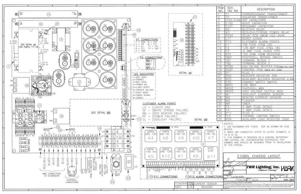
4 APPENDIX CHASSIS COMPONENT LAYOUT... H (REV Q) WIRING DIAGRAM... M (REV J) HOUSING DETAIL... HD0-264 (REV D) INSTALLATION GUIDELINE... INS-264 (REV A) PHOTOCELL HOUSING DETAIL i (REV H) TOWER LIGHTING KIT 201 TO 350 CABLE (REV E) SIDELIGHT MOUNT ASSEMBLY (REV A) TIMING/CONTROL PCB... H01-226B (REV F) HIGH VOLTAGE RECTIFIER PCB... H02-226A (REV A) RELAY PCB w/alarm LOCKOUT ELIMINATION MODIFICATION... H03-264A OL1VLED2 (L810 OBSTRUCTION LIGHT) i (REV E) LED BEACON AND SIDELIGHT CURRENT SENSOR L865/864 LED DUAL BEACON ASSEMBLY i (REV A) JUNCTION BOX DETAIL (REV A) WRAPLOCK FASTENING DETAIL
5 1.0 INTRODUCTION DUAL MEDIUM INTENSITY LED/STROBE The TWR Lighting, Inc. (TWR ) Model E-1DBSL Type L-864/L-865 Controller has been designed and built to the Federal Aviation Advisory Circular 150/ G, with safety and reliability in mind. TWR is committed to providing our customers with some of the best products and services available. TWR welcomes you to our family of fine products and we look forward to servicing your needs now and in the future. 1.1 APPLICATION The E-1DBSL Controller is for use on lighting structures or towers (201' to 350' AGL) that are approved to be lighted with Dual Red LED / White Strobe Flashing Medium Intensity in accordance with the Federal Aviation Administration's (FAA) Advisory Circular 70/7460-1K. 1.2 SPECIFICATIONS OF EQUIPMENT Dimensions: Controller (H X W X D) / Weight 18.0" X 16.0" X 9.25" / 45.0 lbs Mounting Dim (H X W) 18.74" X 12.0" Beacon Height / Weight 27.0" / 80 lbs Cable Diameter / Weight per 100 ft..625" +/- 10% 24 lbs Electrical Voltage: Intensity: White Daymode Red Nightmode White Nightmode (Back-up mode) 120V AC +/- 10% 60 Hz (Standard) 240V AC +/- 10% 60 Hz (Available) 20,000 +/- 25% Effective Candelas 2,000 +/- 25% Effective Candelas 2,000 +/- 25% Effective Candelas Beam Spread: Horizontal 360 Vertical 3 Minimum Flash Rate: White Daymode Red Nightmode White Nightmode (Back-up mode) Wattage: Daymode Red Nightmode White Nightmode Temperature: 40 fpm +/- 2 fpm 30 fpm +/- 2 fpm 40 fpm +/- 2 fpm 95 Watts 40 Watts 35 Watts +55 C / -55 C Beacon Wind Load: 2.1 ft 2 1
6 2.0 INSTALLATION DUAL MEDIUM INTENSITY LED/STROBE WARNING DANGER!!! THIS SYSTEM OPERATES AT HIGH VOLTAGE LEVELS THAT COULD BE LETHAL TO SERVICE PERSONNEL. ALL INSTALLATION AND MAINTENANCE WORK MUST BE DONE BY QUALIFIED SERVICE PERSONNEL ONLY. WHEN PERSONNEL IS INSTALLING SYSTEM OR PERFORMING MAINTENANCE ON THIS SYSTEM, MAKE SURE THE POWER IS TURNED OFF AT THE SERVICE BREAKER PANEL!! READ AND UNDERSTAND THE THEORY OF OPERATION AND ITS SAFETY MESSAGES BEFORE ATTEMPTING INSTALLATION/MAINTENANCE OF THIS SYSTEM. DO NOT ATTEMPT TO DEFEAT THE INTERNAL SAFETY SWITCHES IN THE CONTROLLER AND STLDBEACON!! 2.1 POWER SUPPLY CONTROL CABINET MOUNTING The power supply control cabinet can be located at the base of the structure or in an equipment building. Mounting dimensions can be found in Section 1.2, on page 1. Pay particular attention when choosing your controller mounting location to ensure proper door opening and room for service personnel. Refer to installation drawings INS-264, and HDO-264, for ease of install. 2.2 PHOTOCELL HOUSING The standard photocell housing is supplied with a 20' pigtail of 16 AWG type TFFN wire. On occasion in mounting of the photocell an additional amount of wire may be required. Refer to drawing , for proper assistance on determining gauge of wire for your specific needs. 2
7 2.3 PHOTOCELL WIRING (Refer to Drawings HDO-264 and H40-264) If the control cabinet is mounted inside an equipment building, the photocell should be mounted vertically on ½ conduit outside the building above the eaves facing north. Wiring from the photocell housing socket to the control cabinet should consist of one (1) each; red, black, and white wires. The white wire is connected to the socket terminal marked "N," the black wire is connected to the socket terminal marked "Li," and the red wire is connected to the socket terminal marked "Lo." The photocell should be positioned so that it does not "see" ambient light, which would prevent it from switching to the nightmode. If the control cabinet is mounted outside an equipment building, the photocell should be mounted vertically on ½ conduit so the photocell is above the control cabinet. Care must be taken to assure that the photocell does not "see" any ambient light that would prevent it from switching into the nightmode. The photocell housing socket wiring is the same as above Connect the BLACK wire from the photocell to TB Connect the RED wire from the photocell to TB Connect the WHITE wire from the photocell to TB Install the photocell into the receptacle and twist to the right while depressing to lock into place. 2.4 POWER WIRING (Refer to Drawing H40-264) Power wiring to the control cabinet should be in accordance with local methods and the National Electric Codes (NEC) A 15 amp circuit breaker is recommended at service panel Connect the "HOT" side of the 120V AC line to TB Connect the "NEUTRAL" side of the 120V AC line to TB
8 2.4.4 Connect the AC ground to the ground stud to the lower right of the terminal block TB Controller panel should be connected to the tower and/or building grounding system with the exception of installations on AM RF applications where controller grounding to earth ground is prohibited. Ground the controller only to the tower itself using a suitable RF ground. 2.5 TOWER LIGHTING KIT When installing this system, the customer will need to use strobe cable wiring method to wire the STLDBEACON2A. Refer to tower kit drawing 602, for cable installations. WARNING DANGER!!! THIS SYSTEM OPERATES AT HIGH VOLTAGE LEVELS THAT COULD BE LETHAL TO SERVICE PERSONNEL. ALL INSTALLATION AND MAINTENANCE WORK SHOULD BE DONE BY QUALIFIED SERVICE PERSONNEL ONLY. WHEN PERSONNEL IS INSTALLING SYSTEM OR PERFORMING MAINTENANCE ON THIS SYSTEM, MAKE SURE THE POWER IS TURNED OFF AT THE SERVICE BREAKER PANEL!! READ AND UNDERSTAND THE THEORY OF OPERATION AND ITS SAFETY MESSAGES BEFORE ATTEMPTING INSTALLATION/MAIN- TENANCE OF THIS SYSTEM. DO NOT ATTEMPT TO DEFEAT THE INTERNAL SAFETY SWITCHES IN THE CONTROLLER AND STLDBEACON!! LED Red Beacon Mounting and Wiring (Refer to Drawings HDO-264, and INS-264) Bolt the STLDBEACON2A to the mounting plate using four 5/8" x 1 1/4" galvanized bolts that are supplied. Installer should make sure to check for full thread engagement on Anco locknut. Allow 16" clearance in back of the hinge (25" from the center of the base) to tilt lens back without hitting an obstruction. 4
9 Level the STLDBEACON2A using the spirit level at the base of the lens. Shims may be used under beacon base or triple nutting each bolt with palnuts on all four (4) nuts Slip the electrical cable for the STLDBEACON2A through the watertight connector (cable gland bushing), and tighten the gland nut to make a watertight seal. Attach the wires to the terminal strip as follows: Tower Kit Wiring Connect Cable To Lamp platform Terminal Wire Color Match Wire Color Block Number 10 Gauge Red 16 Gauge Red 1 14 Gauge White/Green 16 Gauge White/Green 2 16 Gauge Brown 16 Gauge Brown 3 16 Gauge Blue 16 Gauge Blue 4 10 Gauge Black 16 Gauge Black 5 14 Gauge White 16 Gauge White 6 14 Gauge Green 16 Gauge Green 7 10 Gauge Red/Black 16 Gauge Red/Black 8 16 Gauge Bare Wire Beacon Base Install wiring between the controller and the beacon utilizing strobe cable. (TWR LIGHTING CANNOT WARRANTY SYSTEMS THAT EMPLOY SPLICING CABLE.) Refer to drawings HDO-264, and 602, for installation of light kits. Following these minimum guidelines, as well as any local or end user additional requirements, installing light kits will require lifting of the cable by the supplied cable grip or conduit to affix to the tower. Always work safely and adhere to all OSHA Safety Guidelines when lifting wiring or working on the structure or tower itself. It is the installer s responsibility to install the lighting kit in a safe manner. Installers can request from OSHA their requirements 29CFT , and 29CFR , to ensure compliance to regulations. NOTE: On occasion, a set of custom lighting kit drawings may be specifically requested by a customer and installed in this manual. In cases such as this, the drawings will precede the manual if a conflict occurs. 5
10 All the necessary information for wiring the STLDBEACON2A and sidelights is contained on the tower kit drawing 602. The connections for the STLDBEACON2A and sidelights in the controller are as follows: Connect the 10 gauge RED/BLACK wire from STLDBEACON2A wiring to TB Connect the 10 gauge BLACK wire from STLDBEACON2A wiring to TB Connect the 14 gauge WHITE wire from STLDBEACON2A wiring to TB Connect the 16 gauge BROWN wire from STLDBEACON2A wiring to TB Connect the 16 gauge BLUE wire from STLDBEACON2A wiring to TB Connect the 10 gauge RED wire from STLDBEACON2A wiring to Fuse Block marked B Connect the 14 gauge WHITE/GREEN wire from STLDBEACON wiring to TB Connect the 14 gauge GREEN wire from STLDBEACON2A ground back panel Connect the NEUTRAL wire from sidelight wiring to TB Connect the RED wire from the sidelight wiring to Fuse Block marked S Connect the ground wire (if cable is used) from sidelight wiring to ground screw left of TB1. 6
11 2.6 ALARM WIRING Individual alarm contacts (Form C) are provided for strobe failures, power failure, and photocell on. It is left up to the customer or installer on how they choose to utilize these contacts with their monitoring equipment. External monitoring equipment is available. Please inquire within the sales staff at the factory for models available and pricing. Alarm configurations are shown on drawings H40-264, and M White Strobe Failure (SF) Connect the customer's alarm common to plug P12, terminal #5. Connect the customer's alarm wire to plug P12, terminal #6, for normally open (or) terminal #4, for normally closed monitoring Lights On (LO) Nighttime Connect the customer's alarm common to plug P12, terminal #2. Connect the customer's alarm wire to plug P12, terminal #1, for normally open (or) terminal #3, for normally closed monitoring Power Failure (PF) Connect the customer's alarm common to plug P12, terminal #11. Connect the customer's alarm wire to plug P12, terminal #12, for normally open (or) terminal #10, for normally closed monitoring LED Red Beacon Burnout (BB) Connect the customer's alarm common to plug P12, terminal #8. Connect the customer's alarm wire to plug P12, terminal #7, for normally open (or) terminal #9, for normally closed monitoring Sidelight Failure (SL) Connect the customer's alarm common to plug P12, terminal #14. Connect the customer's alarm wire to plug P12, terminal #15, for normally open (or) terminal #13, for normally closed monitoring. 7
12 2.7 ALARM TESTING To test alarms, follow these procedures using an "ohm" meter between alarm common and alarm points White Strobe Failure (SF) White strobe failure testing can be performed in the daymode operation. Check for status of strobe beacon. Turn "on" switch S1 on PCB 1, and status should change after an eight (8) second delay. After test, turn switch S1 to the normal operating position Lights On (LO) When controller turns red light mode ON, lights on relay energize, indicating red system functional Power Failure (PF) While the controller is in normal operation, shut off power to the controller at the breaker panel. Alarm should be prompt. Reset the breaker to resume normal operation LED Red Beacon Burnout (BB) Controller should be in the nightmode of operation when performing this test. Pull Fuse Block marked F5 to cause failure. System will then operate in fail mode white strobe. After test, re-engage fuse switch F Sidelight Failure (SL) Controller should be in the nightmode of operation. Check status of operation. Pull fuse switch F4 open. Alarm should occur within five (5) seconds. After test, re-engage fuse switch F4. 8
13 3.0 THEORY OF OPERATION DUAL MEDIUM INTENSITY LED/STROBE 3.1 THE POWER SUPPLY The AC line is sent to transformers T1 through fuse F1, MOVMOD, and relay K1. In order for K1 to energize and complete the circuit to T1, the safety interlock switches (CSS & BSS) must be closed. The BSS (beacon safety switch) is located in the base of the beacon. In order for the system to operate, the beacons and the power supply must be closed and secured. The CSS (cabinet safety switch) is located in the enclosure door of the control cabinet. This switch is a three (3) position switch that can be pulled out or depressed by closing the door to complete the circuit. Transformer T1 secondary outputs are around 1,100V AC. These outputs are sent to the high voltage rectifier PCB (PCB #2) and converts the 1,100V AC to around +550V DC and -550V DC in daymode operation. This high voltage is then used to charge energy storage capacitor bank C103-C109. Resistor R31 is bypassed through K5 during daymode operation. When the light level drops below 3 foot candles, the photocell supplies 120V AC to relay K3, and energizes it. The power is switched from the T1 to the red beacon control circuit. That consists of a flasher (M3) and a timing module (M4), which will flash the beacon, and a current sensing module (M2), which detects failures. In the event of LED beacon failure or flasher failure, the K9 relay (failsafe relay) will remove power from the K3 relay, de-energizing it. The power is then switched back to the strobe control circuit (T1). The photocell continues to supply 120V AC to the controller. This voltage is supplied to the K5 relay, which removes C103-C109 from the discharge path leaving capacitor C102 in the circuit for failsafe mode operation. Transformer T1 secondary outputs are converted from 1,100V AC at the PCB #2 to around +700V DC and -550V DC for failsafe mode operation. This high voltage is then used to charge the energy storage capacitor C102 through the current limiting resistor R31, and the steering diode D5. The energy storage capacitor bank is connected to the flashtube through the interconnecting tower wiring. 9
14 3.2 THE FLASHTUBE The flashtubes FT1 (daymode) is a quartz tube containing two (2) electrodes. The electrode at the positive (+) end is called the anode and is connected to the positive side of the storage capacitors through inductor L1. The electrode at the negative (-) end of the tube is called the Cathode, and is connected to the negative (-) side of the energy storage capacitors banks. The flashtube contains a gas called Xenon. When the high voltage energy in the storage capacitors is connected to the flashtube, nothing will happen since Xenon in its natural state is not a conductor of electricity. However, when a very short duration high voltage pulse is impressed on the trigger element of the tube (via the power supply and trigger transformer T4), the Xenon gas is ionized and thereby becomes a good conductor of electricity. This allows the electrical energy in the storage capacitors to discharge rapidly through the flashtube, which converts this energy to light energy and heat energy. When the voltage stored in the capacitors discharges to a low level, the Xenon gas can no longer sustain conduction and since the short trigger pulse is gone by this time, it deionizes returning to its non-conducting state until another trigger pulse arrives to repeat the process. Meanwhile, the storage capacitor is being recharged by the transformer and the high voltage rectifiers. 3.3 LED BEACON When the photocell turns on at nightfall, that sends 120V AC to Relay K3, and energizes it. The power is switched to red beacon control circuit. That consists of a flasher (M3), a timing module (M4), and a current sensing module (M2). These modules are used to flash the LED Beacon and detect the failures, as well. 3.4 TIMING CIRCUIT The timing circuit is contained entirely on printed circuit board #1. The timing circuit has its own power supply. This circuit converts the AC voltage to approximately 12V DC, which is used to supply all of the components in this circuit. It uses this low voltage DC to generate pulses that control the flash rate of the flashtube. It actually generates two (2) groups of pulses. The first is a pulse approximately once every 1.5 seconds to operate the flashtube during daylight hours. The second is a burst at 100 Hz to elongate the apparent flash during the nighttime hours at reduced flash energy when it failsafes in nightmode. 10
15 3.5 TRIGGER CIRCUIT The trigger circuit is supplied by transformer T2 secondary windings. The 250V AC is converted to DC, which is stored in a storage capacitor much like the action of the high voltage circuit. The main difference is that the storage capacitor is much smaller. The trigger circuit receives the pulses generated by the timing circuit. It releases its stored energy with each pulse and delivers it to the flashtube's trigger element to initiate each flash. 3.6 ALARM CIRCUITS White Strobe Failure (SF) White Strobe Failure alarm circuit monitors each flash of the daymode flashtube within the beacon. If the flashtube fails to flash (for any reason), the alarm circuit operates relay K11, (on PCB #3) which the customer can connect to their alarm transmitting devices. The alarm point can be accessed on P12 of PCB # LED Red Beacon Burnout (BB) When LED Red Beacon burns out, or fails to flash, a signal from Module M2 will energize the K8 relay on PCB #3, then K8 will energize K10, for LED Red Beacon Alarm. Alarm point can be accessed on P12, PCB # Power Failure (PF) The power failure alarm relay is energized during normal operation. If the power is removed for any reason, then relay K6 will drop, creating an alarm for the customer s alarm-transmitting device Sidelight Failure (SL) Module M1 monitors the current flowing to the sidelights. This module can monitor from 1-4 lamps. Factory setting is generally for three (3) lamps. When the current falls below two (2) lamps (one [1] lamp less than the factory setting), then the onboard relay will engage, creating an alarm which is then sent to P12. 11
16 3.7 BLEEDER CIRCUIT The bleeder circuit is the most important safety item in this system. It consists of resistor R32 connected to the high voltage storage capacitor through relay K2. When the AC line voltage is turned off, the relay will close allowing the resistors to discharge the high voltage stored in the capacitor banks below 50V in 30 seconds. **CAUTION** NEVER RELY ON THIS CIRCUIT TO RENDER THIS SYSTEM HARMLESS. ANY DEFECT IN THIS CIRCUIT COULD ALLOW A HAZARDOUS HIGH VOLTAGE CHARGE TO REMAIN ON THE STORAGE CAPACITORS. ALWAYS WAIT AT LEAST 30 SECONDS AFTER POWER HAS BEEN TURNED OFF BEFORE STARTING ANY WORK ON THIS SYSTEM. ALWAYS MEASURE THE VOLTAGE ON THE STORAGE CAPACITORS WITH A VOLTMETER BEFORE STARTING ANY OTHER WORK ON THIS SYSTEM. NEVER ATTEMPT TO DEFEAT THE SAFETY INTERLOCKS. 3.8 DIAGNOSTIC CIRCUITS The diagnostic circuit is provided as a means of making system checks and maintenance more convenient. This circuit is entirely contained on the printed circuit boards PCB #1 and PCB #2. The circuits that are contained on PCB #1 and PCB #2 are as follows: Control Power On (PCB #1, LED4) Line from the 120V AC input is sent through safety switches CSS, BSS, isolation transformer T2, fuse F3, and Relay K1 to PCB #1. Once this low voltage is at PCB #1, it is sent to a step down transformer, then it is rectified, and then sent to LED4 (D15). If for any reason power is interrupted, STLDBEACON2A opened, controller door open, blown F3 fuse, failed relay, etc.) LED4 would be extinguished. 12
17 3.8.2 High Voltage (PCB #2, LED 1, #D14) The Cathode side of the high voltage HV is routed through a current limiting resistor. When the unit is in daymode, LED 1, D14 will be at full brightness when the capacitors are at full charge, but dims with the discharging of the storage capacitors. A constant intensity indicates that high voltage is present but capacitors are not discharging (check other indicators for fault). When the red LED fails to glow, then the high voltage is no longer present Trigger Voltage (PCB #1, LED6) The voltage from secondary of T1 is sent to PCB #1, then rectified for trigger circuit. The LED6 is connected to the trigger voltage via R30. Under normal circumstances, the red LED must be flashing synchronously with the strobe. An absence of this indication means that the voltage is no longer present Nightmode Output voltage from the photocell (SSR) energizes K4 on PCB #3. The circuit switches the input power to the red circuit that in turn will operate the LED Red Beacon. If a failure in the LED Red Beacon occurs, the control circuit will switch power back to the white strobe for failsafe as described in the next section Failsafe Mode (PCB #1, LED7) Since the power switches back to the strobe circuit, the photocell (SSR) energizes RYL1 on the main PCB #1 that will send 12V to light LED7, and set timing circuit operating in nightmode as well Primary Timing (PCB #1, LED8) The primary timing pulses are received at LED8 (D3). LED8 will flash according to the pulses received from the timing circuit. If LED8 fails to flash, then the primary timing circuit has failed. Check LED9 (D28) for secondary timing operation. The strobe unit should produce 40 (+/-2) pulses per minute. 13
18 3.8.6 Timing Signal Verify (PCB #1, LED9) Timing pulses (either primary or secondary) are received at LED9 (D28). The LED will flash according to the pulses received from the timing circuit, but should be 40 +/-2 FPM. In the unlikely event that this LED is out, then total timing failure has occurred Flash Verified (PCB #1, LED5) Current from the Cathode side of the flashtube (FTC) is sent through the current sensing transformer T4 on PCB #1. T4 will send a pulse to the gate of the SCR's Q13, and turn it on. Capacitor C15, which is fully charged via Q13, will send voltage to LED5. After each confirmed flash, LED5 will blink. Absence of a blinking LED signifies that the strobe beacon has ceased to flash Strobe Fail Test (PBC #1, LED2) Switch S1, when turned downward, cuts off the timing signal to the trigger circuit and extinguishes LED9 (D28). Then LED2 (D25) flashes to confirm the trigger circuit is disabled. At this time, a strobe alarm should be received at P12. The normal position of switch S1 is on (switch upward). 14
19 4.0 TROUBLESHOOTING DUAL MEDIUM INTENSITY LED/STROBE Much of the troubleshooting of this system will consist of correcting a "beacon out" situation. There may also be a failure mode where the flashtube is still flashing, but at the wrong rate or the wrong intensity. You must study and understand the safety messages and the theory of operation before attempting any service on this system. Servicing this system must be done by qualified personnel only. ***W A R N I N G H I G H V O L T A G E*** THIS SYSTEM OPERATES AT HIGH VOLTAGE LEVELS THAT COULD BE LETHAL TO SERVICE PERSONNEL. ALL INSTALLATION AND MAINTENANCE WORK MUST BE DONE BY QUALIFIED SERVICE PERSONNEL. READ AND UNDERSTAND THE THEORY OF OPERATION AND ITS SAFETY MESSAGES BEFORE ATTEMPTING INSTALLATION OF THIS SYSTEM. DO NOT ATTEMPT TO DEFEAT THE INTERNAL SAFETY DEVICES. 4.1 TOOL REQUIREMENTS In order to be prepared to troubleshoot or repair this system, a minimum amount of tools and equipment will be required. A recommendation list includes: 1) 5/16 Flat Electrician's Screwdriver 1) Nut Driver or Socket Set 1) VOM with 600V AC / 1,000V DC range and a 40M ohm scale 15
20 4.2 DIAGNOSTIC EVALUATION The first step in troubleshooting of this system or performing annual maintenance will require the technician to open the controller door. With the power off to the controller, the technician shall look over the controller circuit, and repair or replace any apparent problems, such as loose wire connections, or corroded terminations. After the initial visual checks have been completed, restore power to the controller and pull out on the plunger of the cabinet safety switch (CSS), which is located at the lower right edge of the enclosure. Observe at this time the LEDs located on PCB #1, and PCB #2. Determine, by observation of these LED indicators, if the controller is performing in normal operation. LEDs on PCB #1 are numbered from top to bottom, 1-9. LEDs on PCB #2 are numbered from top to bottom, D14 - D16. The following chart will indicate normal LED operation. INDICATOR OPERATION NORMAL STATUS LED 2 Strobe Fail Test Normal OFF/Flashes in Test Mode LED5 Flash Verify Blinks LED4 Control Power ON Steady ON LED6 Trigger Voltage Steady ON LED7 Failsafe Mode Steady ON During Failsafe Mode Operation LED8 Primary Timing Flashing LED9 Timing Verify Flashing D14 High Voltage #1 Steady ON when Voltage Above 50V DC 16
21 4.3 TROUBLESHOOTING ASSISTANCE Strobe Flash Verify LED - Out Observe high voltage LED (D14) on the high voltage rectifier PCB #2, to determine if it is available. If the LED is dim or out completely, then check the high voltage capacitor bank (C103 - C109 daymode, C102 nightmode) for a short. If no capacitor is found to be shorted, check the resonant cap (C101) for a short. If the resonant cap is okay, replace PCB #2. If the LED is at full illumination, go to the next step Check the status of trigger LED6. If LED is off, check fuse F2. If blown, replace with exact type of fuse. If the fuse blows again, replace PCB #1. Check transformer T1. Replace as necessary. If LED is okay, go to the next step If steps and check out okay, re-lamp the STLDBEACON2A Control Power on LED - Out Check interlock circuit for an open circuit. If open, make the necessary repairs. If okay, check fuse F3 in the cabinet. Replace if bad Primary Timing LED Out Observe the status of the timing LED8. If the LED is dim or out completely, check LED9, and if dim or out, replace PCB #1. If one or both are lit, you should have timing False or Nonexistent Strobe Alarm (SF) If alarm trips when the system appears to be working normally, or fails to show an alarm when there is an obvious failure, replace PCB #1. 17
22 Check relay K11 coil for an open condition. Normal resistance should be around 2K ohm. If coil is open, replace K The time delay between an actual failure and the point where the relay trips is pre-set at the factory at about eight (8) seconds. This delay period can be tested by throwing on switch S1 (on the PCB #1). When this switch is in the alarm test mode, the flash verified indicator (LED#1) will not be illuminated STLDBEACON2A/Flasher Failure In case a failure occurs in the red beacon portion, either the STLDBEACON2A or flasher failed. The system will operate in the failsafe mode, and have beacon fail alarm at the P12 plug. Pin #8 is common, P#7 is closed, and P#9 is open. To troubleshoot the red beacon portion: 1) turn power off at circuit breaker to reset the light system, 2) pull Relay K8 out of socket, and set SW3 to nightmode (upward position), 3) then turn power on at circuit breaker. Observe the red STLDBEACON2A. IF: Beacon steady burns, replace M3 (Flasher) IF: No light check F5 fuse. If F5 fuse is good, replace the red LED Beacon. 18
23 5.0 MAINTENANCE GUIDE DUAL MEDIUM INTENSITY LED/STROBE **WARNING - HIGH - VOLTAGE** THIS SYSTEM OPERATES AT HIGH VOLTAGE LEVELS THAT COULD BE LETHAL TO SERVICE PERSONNEL. ALL INSTALLATION AND MAINTENANCE WORK MUST BE DONE BY QUALIFIED SERVICE PERSONNEL. READ AND UNDERSTAND THE THEORY OF OPERATION AND ITS SAFETY MESSAGES BEFORE ATTEMPTING INSTALLATION OF THIS SYSTEM. DO NOT ATTEMPT TO DEFEAT THE INTERNAL SAFETY DEVICES. Tools Required: #2 Phillips Screwdriver 3/16 Flat Blade Screwdriver 5.1 FLASHTUBE REPLACEMENT The only required maintenance needed to be performed is the replacement of the flashtube every four (4) years. By following these instructions, maximum safety and performance can be achieved Loosen the single quick open bolt located on upper hinge assembly Open the lens and tilt it back. ALWAYS WAIT AT LEAST 30 SECONDS AFTER OPENING THE STLDBEACON BEFORE STARTING ANY WORK Loosen the three (3) socket screws with a #2 Phillips screwdriver to remove lamp Install the new flashtube, making sure that the pins are aligned with the socket. Make sure tube is flush on the socket Tighten the socket screws snug, then 1/4 turn more Close the lens. Make sure nothing hampers the safety interlock action. 19
24 5.1.7 Re-tighten the single quick open bolt on the STLDBEACON2A hinge. 5.2 RED OBSTRUCTION LIGHTING The only required maintenance needed to be performed is replacement of the lamps in the L-810 fixture. Lamps should be replaced after being operated for not more than 75% of the rated life or immediately upon failure as per FAA Advisory Circular 70/7460-1K. By following these instructions, maximum safety and performance can be achieved. Tools Required: None LED LAMP REPLACEMENT SIDELIGHTS 5.3 PHOTOCELL No maintenance is needed or required, other than replacement as necessary. The photocell is a sealed unit. No maintenance is needed or required, other than replacement as necessary. 20
25 6.0 MAJOR COMPONENTS LIST PART NUMBER DESCRIPTION SCHEMATIC TAG # STJ02003 BEACON SAFETY SWITCH STB uf 1kv CAP C103 - C109 STB99008CSI 3 uf 660V AC CAP C101, C102 STJ02001 CABINET SAFETY SWITCH CSS FNQ10 10 amp FUSE F1 FLQ 1/8 1/8 amp FUSE F2 FUSE.5.5 amp FUSE F3 STFLSHTB8 FLASHTUBE KRPA11AG120V DPDT OCTAL RELAY K5, K1, K7, K9 KRPA5AG120V SPDT OCTAL RELAY K4, K6, K8, K10, K12 SPEC SECOND TIME DELAY ON RELEASE RELAY K11 STJ10016 BLEEDER RELAY K2 INDCTR3001 INDUCTOR BURSTING CHOKE L11 MOV524V15 METAL OXIDE VARISTOR MOV2 V1000LA80A METAL OXIDE VARISTOR MOV3 STT POSITION PLUG P1 STH01226B CONTROL PCB PCB #1 PRD5AYO DAY/NIGHT RELAY K3 STH02226A HIGH VOLTAGE RECTIFIER PCB PCB #2 21
26 6.0 MAJOR COMPONENTS LIST (continued) PART NUMBER DESCRIPTION SCHEMATIC TAG # SPM-120 (This replaces the DTK-120HW) SURGE ARRESTOR 120V AC MOV1 STH03264A RELAY PCB w/alarm LOCKOUT ELIMINATION MODIFICATION PCB # FAA2 (This replaces the V PHOTOCELL PHOTOCELL P2455L Photocell) KTK1 1 amp FUSE F4 KTK2 2 amp FUSE F5 PF-250 (This replaces the FLASHER SOLID STATE M3 FS15530T Flasher) TS14130 TIMER M4 STA ohm 100W R31 STA k 20W R32 STA meg 2W R33 STJ01004 SPDT 15 amp SWITCH SW3 STC05004 ISOLATION TRANSFORMER T2 STC30018 FERRORESONANT TRANSFORMER T1 TERMBLK PART TERM BLK TB1 TERMBLK PART TERM BLK TB2 STJ10008 THERMAL LIMITING SWITCH TLS STLDBEACON2A STROBE LED BEACON 22
27 6.0 MAJOR COMPONENTS LIST (continued) PART NUMBER DESCRIPTION SCHEMATIC TAG # STDBCLENS STBEAGSK2 CLEAR DUAL BEACON LENS BEACON GASKET RM22JA31MR CURRENT SENSOR M1, M2 STC05005 TRIGGER TRANSFORMER STA22011 AUXILIARY LOAD RESISTOR R34 DBTERMBLK8KIT DBTERMBLK10KIT STROBCABLE-3 STCABLEOB STLDBCTUBE-2 STCABLTIE STLDHATPLT DUAL BEACON UPPER TERMINAL BLOCK KIT DUAL BEACON LOWER TERMINAL BLOCK KIT STROBE BEACON CABLE SIDELIGHT CABLE STLDBEACON2A, BOTTOM CLEAR LENS STROBE CABLE TIE STLDBEACON2A HATCH LATCH ASSEMBLY CABLEGRIP1 SINGLE EYE LACE MESH CABLEGRIP3 SINGLE EYE LACE MESH LED120-2RK LED SIDELIGHT V AC RETROFIT KIT ASSEMBLY 23
28 7.0 SUGGESTED PARTS LIST DUAL MEDIUM INTENSITY LED/STROBE QTY PART NUMBER DESCRIPTION 1 STH01226B PCB #1 PRINTED CIRCUIT BOARD 1 STJ10016 BLEEDER RELAY 1 STFLSHTB8 STROBE FLASHTUBE FAA2 (This replaces the P2455L Photocell) V PHOTOCELL 2 FNQ10 10 amp FUSE 2 FLQ18 1/8 amp FUSE 2 FUSE.5 ½ amp FUSE 1 KRPA5AG120 SPDT RELAY 2 KRPA11AG120 DPDT RELAY 1 PRD5AYO (K3) SPDT RELAY 1 PF-250 (This replaces the FS15530T Flasher) FLASHER (M1) 1 TS14130 TIMER (M4) 2 KTK2 2 amp FUSE 2 KTK1 1 amp FUSE BURST CHOKE 1 RM22JA31MR CURRENT SENSORS (M2, and M3) 24
29 Warranty & Return Policy TWR Lighting, Inc. ( TWR ) warrants its products (other than LED Product ) against defects in design, material (excluding incandescent bulbs) and workmanship for a period ending on the earlier of two (2) years from the date of shipment or one (1) year from the date of installation. TWR Lighting, Inc. ( TWR ) warrants its LED Product against defects in design, material and workmanship for a period of five (5) years from the date of shipment. TWR, at its sole option, will, itself, or through others, repair, replace or refund the purchase price paid for LED Product that TWR verifies as being inoperable due to original design, material, or workmanship. All warranty replacement LED Product is warranted only for the remainder of the original warranty of the LED Product replaced. Replacement LED Product will be equivalent in function, but not necessarily identical, to the replaced LED Product. TWR Lighting, Inc. ( TWR ) warrants its LED Product against light degradation for a period of five (5) years from the date of installation. TWR, at its sole option, will, itself, or through others, repair, replace, or refund the purchase price paid for LED Product that TWR verifies as failing to meet 75% of the minimum intensity requirements as defined in the FAA Advisory Circular 150/ G dated 09/26/12. All warranty replacement LED Product is warranted only for the remainder of the original warranty of the LED Product replaced. Replacement LED Product will be equivalent in function, but not necessarily identical, to the replaced LED Product. Replacement parts (other than LED Product ) are warranted for 90 days from the date of shipment. Conditions not covered by this Warranty, or which might void this Warranty are as follows: x x x x x x x Improper Installation or Operation Misuse Abuse Unauthorized or Improper Repair or Alteration Accident or Negligence in Use, Storage, Transportation, or Handling Any Acts of God or Nature Non-OEM Parts The use of Non-OEM parts or modifications to original equipment design will void the manufacturer warranty and could invalidate the assurance of complying with FAA requirements as published in Advisory Circular 150/
30 Warranty & Return Policy (continued) Field Service Labor, Travel, and Tower Climb are not covered under warranty. Customer shall be obligated to pay for all incurred charges. An extensive network of certified and insured Service Representatives is available if requested. Repair, Replacement or Product Return RMA Terms You must first contact our Customer Service Department at to acquire a Return Merchandise Authorization (RMA) number in order to return the product(s). Please have the following information available when requesting an RMA number: x The contact name and phone number of the tower owner or x The contact name and phone number of the contractor x The site name and number x The part number(s) x The serial number(s) (if any) x A description of the problem x The billing information x The Ship To address This RMA number must be clearly visible on the outside of the box. If the RMA number is not clearly labeled on the outside of the box, your shipment will be refused. Please ensure the material you are returning is packaged carefully. The warranty is null and void if the product(s) are damaged in the return shipment. All RMAs must be received by TWR LIGHTING, INC., W. LITTLE YORK RD. #130, HOUSTON, TX , within 30 days of issuance. Upon full compliance with the Return Terms, TWR will replace, repair and return, or credit product(s) returned by the customer. It is TWR s sole discretion to determine the disposition of the returned item(s).
31 Warranty & Return Policy (continued) RMA Replacements Replacement part(s) will be shipped and billed to the customer for product(s) considered as Warranty, pending return of defective product(s). When available, a certified reconditioned part is shipped as warranty replacement with a Return Merchandise Authorization (RMA) number attached. Upon receipt of returned product(s), inspection, testing, and evaluation will be performed to determine the cause of defect. The customer is then notified of the determination of the testing. x Product(s) that is deemed defective and/or unrepairable and covered under warranty - a credit will be issued to the customer s account. x Product(s) found to have no defect will be subject to a $75.00 per hour testing charge (1 hour minimum), which will be invoiced to the customer. At this time the customer may decide to have the tested part(s) returned and is responsible for the return charges. x Product(s) under warranty, which the customer does not wish returned, the customer will be issued a credit against the replacement invoice. RMA Repair & Return A Return Merchandise Authorization (RMA) will be issued for all part(s) returned to TWR for repair. Upon receipt of returned product(s), inspection, testing, and evaluation will be performed to determine the cause of defect. The customer is then notified of the determination of the testing. If the returned part(s) is deemed unrepairable, or the returned part(s) is found to have no defect, the customer will be subject to a $75.00 per hour testing charge (1 hour minimum), which will be invoiced to the customer. Should the returned parts be determined to be repairable, a written estimated cost of repair will be sent to the customer for their written approval prior to any work being performed. In order to have the tested part(s) repaired and/or returned, the customer must issue a purchase order and is responsible for the return shipping charges. RMA Return to Stock Any product order that is returned to TWR for part(s) ordered incorrectly or found to be unneeded upon receipt by the customer, the customer may be required to pay a minimum 20% restocking fee. Product returned for credit must be returned within 60-days of original purchase, be in new and resalable condition, and in original packaging. Once the product is received by TWR it s condition will be evaluated and a credit will be issued only once it is determined that the RMA Return Terms have been met.
32 Warranty & Return Policy (continued) Credits Credits are issued once it is determined that all of the Warranty and Return Terms are met. All credits are processed on Fridays. In the event a Friday falls on a Holiday, the credit will be issued on the following Friday. Freight All warranty replacement part(s) will be shipped via ground delivery and paid for by TWR. Delivery other than ground is the responsibility of the customer. REMEDIES UNDER THIS WARRANTY ARE LIMITED TO PROVISIONS OF REPLACEMENT PARTS AND REPAIRS AS SPECIFICALLY PROVIDED. IN NO EVENT SHALL TWR BE LIABLE FOR ANY OTHER LOSSES, DAMAGES, COSTS, OR EXPENSES INCURRED BY THE CUSTOMER, INCLUDING, BUT NOT LIMITED TO, LOSS FROM FAILURE OF THE PRODUCT(S) TO OPERATE FOR ANY TIME, AND ALL OTHER DIRECT, INDIRECT, SPECIAL, INCIDENTAL, OR CONSEQUENTIAL DAMAGES, INCLUDING ALL PERSONAL INJURY OR PROPERTY DAMAGE DUE TO ALLEGED NEGLIGENCE, OR ANY OTHER LEGAL THEORY WHATSOEVER. THIS WARRANTY IS MADE BY TWR EXPRESSLY IN LIEU OF ALL OTHER WARRANTIES, WHETHER EXPRESSED OR IMPLIED. WITHOUT LIMITING THE GENERALITY OF THE FORGOING, TWR MAKES NO WARRANTY OF MERCHANTABILITY OR FITNESS OF THE PRODUCT(S) FOR ANY PARTICULAR PURPOSE. TWR EXPRESSLY DISCLAIMS ALL OTHER WARRANTIES.
33 RETURN MERCHANDISE AUTHORIZATION (RMA) FORM RMA#: DATE: CUSTOMER: CONTACT: PHONE NO.: ITEM DESCRIPTION (PART NO.): MODEL NO.: ORIGINAL TWR INVOICE NO.: SERIAL NO.: DATED: DESCRIPTION OF PROBLEM: SIGNED: DATE NEEDED: RETURN ADDRESS: PLEASE RETURN PRODUCT TO: W. LITTLE YORK RD. #130 HOUSTON, TX
34 RETURN MERCHANDISE AUTHORIZATION (RMA) FORM RMA#: DATE: CUSTOMER: CONTACT: PHONE NO.: ITEM DESCRIPTION (PART NO.): MODEL NO.: SERIAL NO.: ORIGINAL TWR INVOICE NO.: DATED: DESCRIPTION OF PROBLEM: SIGNED: DATE NEEDED: RETURN ADDRESS: PLEASE RETURN PRODUCT TO: W. LITTLE YORK RD. #130 HOUSTON, TX
35
36
37
38
39
40
41 B SEE NOTE # Parts List ITEM QTY PART NUMBER DESCRIPTION 1 3 OL1/LED 3/4" OBSTRUCTION LIGHT 2 1 T27CG 3/4" CONDULET W/COVER AND GASKET 3 1 EL3430 3/4" 30 ELBOW 4 1 N34T3 3/4" X 3" NIPPLE 5 3 HC402 3/4" NO THREAD CONNECTOR 6 5 A314 3/4" CONDUIT LOCKNUTS 7 1 CONDUIT34 3/4" CONDUIT NOTES: 1. THIS DRAWING IS A TYPICAL INSTALLATION DETAIL FOR 3 OL-1 PER LEVEL SYSTEM. 2. PART # EL3430 MAY BE OMITTED WHEN ARRANGING FOUR LEG TOWERS. 3. PART # COUNDUIT34 CUT TO LENGTH FOR PROPER EXTENTION OF OL1 FROM STRUCTURE (6"-12"). ATTACH PART # HC402 TO UNTHREADED CONDUIT TO COMPLETE ASSEMBLY. 4. USE COUPLING THAT IS PROVIDED BY PART # CONDUIT GREEN WIRE USED ONLY ON LED SIDELIGHTS B JUNCTION BOX TOP VIEW A 6 6 ISOMETRIC VIEW DRAWN jbustamante CHECKED QA MFG APPROVED 1/4/2008 TITLE TWR Lighting, Inc. Enlightened Technology SIDELIGHT MOUNT ASSEMBLY (10' FACE WIDTH MAX) A SIZE B SCALE DWG NO SHEET 1 OF 1 REV A 4 3 The use of non-oem parts or modifications to original equipment design will void the manufacturer warranty and could invalidate the assurance of complying with FAA requirements as published in Advisory Circular 150/ NOTICE: The drawings and photographic images contained herein are the sole property of TWR Lighting, Inc. All information contained herein that is not generally known shall be considered confidential except to the extent the information has been previously established. The drawings and photographic images contained herein may not be reproduced, copied or used as the basis for manufacture or sale or promotion or any other purpose without the expressed written permission of TWR Lighting, Inc. 2 1
42
43
44
45 B * * * * * * * * * * * * * ITEM Parts List QTY PART NUMBER DESCRIPTION 1 OL1VLED2 L810 OBSTRUCTION LIGHT _RE OL 6LED BASE PLATE OL 6LED STAR DISK OL1/2 SERIAL # LABEL 1 A /32" ID RUBBER GROMMET 6 STD05008 LED EMITTER 1 OLG OL GASKET 1 AP SIDELIGHT LENS CLEAR ACYRLIC 1 106V LENS HOLDER RING 6 STE LED VERTICAL PCB 16 18PRSS 1/8 X.45 SS POP RIVET 1 PS90-260/24 POWER SUPPLY 1 20RED #20AWG RED BELDON WIRE 2 WIRENUTBLU BLUE WIRE NUT 2 HC255SS SIDELIGHT LATCH 1 7X7SS 1/16 HOL 7X7 S.S. WIRE 2 12V245 OL LENS CLIP 1 105V SINGLE SIDELIGHT BODY 2 832X14PH 8-32 X 1/4 PH SS SLOT SCREW 2 A1A STAKON CRIMP 1 A314 3/4" CONDUIT LOCKNUT GALV. B * = ITEMS NOT SHOWN FIXTURE 2 WHITE BLACK A VAC SCHEMATIC * GROUND WIRE MUST BE CONNECTED TO PROPERLY PROTECT POWER SUPPLY. FAILURE TO GROUND WILL VOID ALL WARRANTIES. A DRAWN gsebek CHECKED 8/18/2004 QA MFG APPROVED TITLE OL1VLED VAC FAA-OL16LED (L810 OBSTRUCTION LIGHT) DATE REV AUTHOR DESCRIPTION 11/07/14 E JZAMORANO REM. WIRE CONNECT 4 3 SIZE B SCALE 2 DWG NO i SHEET 1 OF 1 1 REV E
46

47
48
49
10810 W. LITTLE YORK RD. #130 HOUSTON, TX VOICE (713) FAX (713) web: IMPORTANT!!!
 FAX (713) web: IMPORTANT!!!") 10810 W. LITTLE YORK RD. #130 HOUSTON, TX 77041-4051 VOICE (713) 973-6905 FAX (713) 973-9352 web: www.twrlighting.com IMPORTANT!!! PLEASE TAKE THE TIME TO FILL OUT THIS FORM COMPLETELY. FILE IT IN A SAFE
10810 W. LITTLE YORK RD. #130 HOUSTON, TX 77041-4051 VOICE (713) 973-6905 FAX (713) 973-9352 web: www.twrlighting.com IMPORTANT!!! PLEASE TAKE THE TIME TO FILL OUT THIS FORM COMPLETELY. FILE IT IN A SAFE
10810 W. LITTLE YORK RD., STE. 130 HOUSTON TX VOICE (713) FAX (713) web: IMPORTANT!!!
 FAX (713) web: IMPORTANT!!!") 10810 W. LITTLE YORK RD., STE. 130 HOUSTON TX 77041-4051 VOICE (713) 973-6905 FAX (713) 973-9352 web: www.twrlighting.com IMPORTANT!!! PLEASE TAKE THE TIME TO FILL OUT THIS FORM COMPLETELY. FILE IT IN
10810 W. LITTLE YORK RD., STE. 130 HOUSTON TX 77041-4051 VOICE (713) 973-6905 FAX (713) 973-9352 web: www.twrlighting.com IMPORTANT!!! PLEASE TAKE THE TIME TO FILL OUT THIS FORM COMPLETELY. FILE IT IN
10810 W. LITTLE YORK RD #130 - HOUSTON TX VOICE (713) FAX (713) web: IMPORTANT!!!
 FAX (713) web: IMPORTANT!!!") 10810 W. LITTLE YORK RD #130 - HOUSTON TX 77041-4051 VOICE (713) 973-6905 - FAX (713) 973-9352 web: www.twrlighting.com IMPORTANT!!! PLEASE TAKE THE TIME TO FILL OUT THIS FORM COMPLETELY. FILE IT IN A
10810 W. LITTLE YORK RD #130 - HOUSTON TX 77041-4051 VOICE (713) 973-6905 - FAX (713) 973-9352 web: www.twrlighting.com IMPORTANT!!! PLEASE TAKE THE TIME TO FILL OUT THIS FORM COMPLETELY. FILE IT IN A
4300 WINDFERN RD. SUITE 100 HOUSTON, TX VOICE (713) FAX (713) WEB: twrlighting.com IMPORTANT!!!
 FAX (713) WEB: twrlighting.com IMPORTANT!!!") 4300 WINDFERN RD. SUITE 100 HOUSTON, TX 77041-8943 VOICE (713) 973-6905 FAX (713) 973-9852 WEB: twrlighting.com IMPORTANT!!! PLEASE TAKE THE TIME TO FILL OUT THE FORM COMPLETELY. FILE IN A SAFE PLACE.
4300 WINDFERN RD. SUITE 100 HOUSTON, TX 77041-8943 VOICE (713) 973-6905 FAX (713) 973-9852 WEB: twrlighting.com IMPORTANT!!! PLEASE TAKE THE TIME TO FILL OUT THE FORM COMPLETELY. FILE IN A SAFE PLACE.
10810 W. LITTLE YORK RD. STE HOUSTON, TX VOICE (713) FAX (713) web: IMPORTANT!!!
 FAX (713) web: IMPORTANT!!!") 10810 W. LITTLE YORK RD. STE. 130 - HOUSTON, TX 77041-4051 VOICE (713) 973-6905 - FAX (713) 973-9352 web: www.twrlighting.com IMPORTANT!!! PLEASE TAKE THE TIME TO FILL OUT THIS FORM COMPLETELY. FILE IT
10810 W. LITTLE YORK RD. STE. 130 - HOUSTON, TX 77041-4051 VOICE (713) 973-6905 - FAX (713) 973-9352 web: www.twrlighting.com IMPORTANT!!! PLEASE TAKE THE TIME TO FILL OUT THIS FORM COMPLETELY. FILE IT
4300 WINDFERN RD STE 100 HOUSTON TX VOICE (713) FAX (713) web: IMPORTANT!!!
 FAX (713) web: IMPORTANT!!!") 00 WINDFERN RD STE 00 HOUSTON TX 770-89 VOICE (7) 97-6905 FAX (7) 97-95 web: www.twrlighting.com IMPORTANT!!! PLEASE TAKE THE TIME TO FILL OUT THIS FORM COMPLETELY. FILE IT IN A SAFE PLACE. IN THE EVENT
00 WINDFERN RD STE 00 HOUSTON TX 770-89 VOICE (7) 97-6905 FAX (7) 97-95 web: www.twrlighting.com IMPORTANT!!! PLEASE TAKE THE TIME TO FILL OUT THIS FORM COMPLETELY. FILE IT IN A SAFE PLACE. IN THE EVENT
4300 WINDFERN RD #100 HOUSTON TX VOICE (713) FAX (713) web: IMPORTANT!!!
 FAX (713) web: IMPORTANT!!!") 4300 WINDFERN RD #100 HOUSTON TX 77041-8943 VOICE (713) 973-6905 FAX (713) 973-9352 web: www.twrlighting.com IMPORTANT!!! PLEASE TAKE THE TIME TO FILL OUT THIS FORM COMPLETELY. FILE IT IN A SAFE PLACE.
4300 WINDFERN RD #100 HOUSTON TX 77041-8943 VOICE (713) 973-6905 FAX (713) 973-9352 web: www.twrlighting.com IMPORTANT!!! PLEASE TAKE THE TIME TO FILL OUT THIS FORM COMPLETELY. FILE IT IN A SAFE PLACE.
IMPORTANT!!!! MODEL # E-1DB 1/13/2000
 1/13/2000 IMPORTANT!!!! PLEASE TAKE THE TIME TO FILL OUT THE FORM COMPLETELY. FILE IN A SAFE PLACE. IN THE EVENT YOU EXPERIENCE PROBLEMS WITH OR HAVE QUESTIONS CONCERNING YOUR CONTROLLER, THE FOLLOWING
IMPORTANT!!! 4300 WINDFERN RD., SUITE HOUSTON TX VOICE (713) FAX (713) web:
 FAX (713) web:") 4300 WINDFERN RD., SUITE 100 - HOUSTON TX. 77041-8943 VOICE (713) 973-6905 - FAX (713) 973-9352 web: www.twrlighting.com IMPORTANT!!! PLEASE TAKE THE TIME TO FILL OUT THE FORM COMPLETELY. FILE IT IN A
4300 WINDFERN RD., SUITE 100 - HOUSTON TX. 77041-8943 VOICE (713) 973-6905 - FAX (713) 973-9352 web: www.twrlighting.com IMPORTANT!!! PLEASE TAKE THE TIME TO FILL OUT THE FORM COMPLETELY. FILE IT IN A
4300 WINDFERN RD SUITE 100 HOUSTON TX VOICE (713) FAX (713) WEB: IMPORTANT!!!
 FAX (713) WEB: IMPORTANT!!!") 4300 WINDFERN RD SUITE 00 HOUSTON TX 7704-8943 VOICE (73) 973-6905 FAX (73) 973-9352 WEB: www.twrlighting.com IMPORTANT!!! PLEASE TAKE THE TIME TO FILL OUT THIS FORM COMPLETELY. FILE IT IN A SAFE PLACE.
4300 WINDFERN RD SUITE 00 HOUSTON TX 7704-8943 VOICE (73) 973-6905 FAX (73) 973-9352 WEB: www.twrlighting.com IMPORTANT!!! PLEASE TAKE THE TIME TO FILL OUT THIS FORM COMPLETELY. FILE IT IN A SAFE PLACE.
4300 WINDFERN RD SUITE 100 HOUSTON TX VOICE (713) FAX (713) web: twrlighting.com IMPORTANT!!!
 FAX (713) web: twrlighting.com IMPORTANT!!!") 4300 WINDFERN RD SUITE 100 HOUSTON TX 77041-8943 VOICE (713) 973-6905 FAX (713) 973-9352 web: twrlighting.com IMPORTANT!!! PLEASE TAKE THE TIME TO FILL OUT THIS FORM COMPLETELY. FILE IT IN A SAFE PLACE.
4300 WINDFERN RD SUITE 100 HOUSTON TX 77041-8943 VOICE (713) 973-6905 FAX (713) 973-9352 web: twrlighting.com IMPORTANT!!! PLEASE TAKE THE TIME TO FILL OUT THIS FORM COMPLETELY. FILE IT IN A SAFE PLACE.
10810 W. LITTLE YORK RD. #130 HOUSTON, TX VOICE (713) FAX (713) web: IMPORTANT!!!!
 FAX (713) web: IMPORTANT!!!!") 10810 W. LITTLE YORK RD. #130 HOUSTON, TX 77041-4051 VOICE (713) 973-6905 FAX (713) 973-9352 web: www.twrlighting.com IMPORTANT!!!! PLEASE TAKE THE TIME TO FILL OUT THE FORM COMPLETELY. FILE IN A SAFE
10810 W. LITTLE YORK RD. #130 HOUSTON, TX 77041-4051 VOICE (713) 973-6905 FAX (713) 973-9352 web: www.twrlighting.com IMPORTANT!!!! PLEASE TAKE THE TIME TO FILL OUT THE FORM COMPLETELY. FILE IN A SAFE
Troubleshooting Guide For FG3000 Dual Medium Intensity Lighting System
 Troubleshooting Guide For FG3000 Dual Medium Intensity Lighting System TABLE OF CONTENTS SECTION 1.0 - GENERAL INFORMATION...1 1.1 Scope...1 1.2 General Description...1 1.3 Safety Precautions...2 1.4 Honeywell
Training Guide For FG3000 Dual Medium Intensity Lighting System
 Training Guide For FG3000 Dual Medium Intensity Lighting System Manual No. MPR-00000009-001 Honeywell Airport Systems 2162 Union Pl. Simi Valley, CA 93065 Phone: (805) 581-5591 Fax: (805) 581-5032 http://www.oblighting.com
FlashGuard 3000B Dual Lighting System Troubleshooting Guide
 FlashGuard 3000B Dual Lighting System Troubleshooting Guide Table of Contents Section Flashhead (Strobe) Troubleshooting Flowchart 1 Multiple Strobe Troubleshooting Flowchart 2 Sidelight Troubleshooting
DESCRIPTIVE AND INSTALLATION INSTRUCTION MANUAL FOR MODEL G1000 AND H1000 SERIES ANNUNCIATORS
 DESCRIPTIVE AND INSTALLATION INSTRUCTION MANUAL FOR MODEL G1000 AND H1000 SERIES ANNUNCIATORS SEEKIRK, INC. 2420 Scioto Harper Dr. Columbus, OH 43204 Tel: (614) 278-9200 FAX: (614) 278-9257 email: seekirk@seekirk.com
DESCRIPTIVE AND INSTALLATION INSTRUCTION MANUAL FOR MODEL AH1000, BH1000, AND EH1000 SERIES ANNUNCIATORS
 DESCRIPTIVE AND INSTALLATION INSTRUCTION MANUAL FOR MODEL AH1000, BH1000, AND EH1000 SERIES ANNUNCIATORS SEEKIRK, INC. 2420 Scioto Harper Dr. Columbus, OH 43204 Tel: (614) 278-9200 FAX: (614) 278-9257
CLIMAGUARD Air-to-Air Outdoor Heat Exchangers INSTRUCTION MANUAL. Rev. H 2015 Pentair Equipment Protection P/N
 CLIMAGUARD Air-to-Air Outdoor Heat Exchangers TX23, TX33, TX38, TX52 Model INSTRUCTION MANUAL Rev. H 2015 Pentair Equipment Protection P/N 10-1008-221 87976519 TABLE OF CONTENTS RECEIVING THE HEAT EXCHANGER...3
MAYFIELD CEILING FAN LISTED E ITEM # MODEL #BTH44ABZC5C BTH44BNK5C Español p. 20 ATTACH YOUR RECEIPT HERE.
 Harbor Breeze is a registered trademark of LF, LLC. All Rights Reserved. ITEM #0331094 0331096 MAYFIELD CEILING FAN MODEL #BTH44ABZC5C BTH44BNK5C Español p. 20 ATTACH YOUR RECEIPT HERE Serial Number Purchase
Installation, Operation & Service Manual
 Installation, Operation & Service Manual WARNING Improper installation, adjustment, alteration, service or maintenance can result in death, injury or property damage. Read the Installation, Operation and
HUGHEY & PHILLIPS, LLC.
 HUGHEY & PHILLIPS, LLC. Installation and Operation Guide HORIZON MEDIUM INTENSITY DUAL LED LIGHTING SYSTEM CONTROLLER FAA TYPES A1, D1, & E1 MANUAL EPM-00000044-001 Revision F Hughey & Phillips, LLC. 240
ST. KITTS CEILING FAN
 ITEM #0845047 ST. KITTS CEILING FAN MODEL #40829 Questions, problems or missing parts? Before returning this item to your retailer, call our customer service department at 1-800-643-0067, Monday - Thursday,
36 IN. ELECTIC FIREPLACE FMI MODEL # LEF36 Mounting Base Feet and Wall Mounting Bracket Included
 F3610G FMI PRODUCTS, LLC 36 IN. ELECTIC FIREPLACE FMI MODEL # LEF36 Mounting Base Feet and Wall Mounting Bracket Included FMI Products, LLC TABLE OF CONTENTS Safety Information... 3 Operating Instructions...
ITEM # , , PAWTUCKET CEILING FAN MODEL #40958, 40959, 40047
 ITEM #0803775, 0721899, 0807427 PAWTUCKET CEILING FAN MODEL #40958, 40959, 40047 Harbor Breeze is a registered trademark of LF, LLC. All Rights Reserved. Español p. 20 ATTACH YOUR RECEIPT HERE Serial Number
TILGHMAN CEILING FAN. LISTED For Damp Location E ITEM # MODEL #WCK52LMW5N WCK52NWZ5N. Español p. 20 ATTACH YOUR RECEIPT HERE
 ITEM #0294980 0294981 TILGHMAN CEILING FAN Harbor Breeze is a registered trademark of LF, LLC. All Rights Reserved. MODEL #WCK52LMW5N WCK52NWZ5N Español p. 20 ATTACH YOUR RECEIPT HERE Serial Number Purchase
ITEM # BUILDER S SERIES CEILING FAN MODEL #41391
 Harbor Breeze Harb or Breeze ITEM #0915543 BUILDER S SERIES CEILING FAN MODEL #41391 Harbor Breeze is a registered trademark of LF, LLC. All Rights Reserved. Español p. 18 ATTACH YOUR RECEIPT HERE Purchase
460H INSTALLATION & OPERATION MANUAL REMOTE STROBE POWER SUPPLY IMPORTANT: 460H TM REMOTE STROBE POWER SUPPLY
 INSTALLATION & OPERATION MANUAL 460H TM REMOTE STROBE POWER SUPPLY 460H REMOTE STROBE POWER SUPPLY Contents: Introduction... 2 Standard Features... 2 Specifications... 2 Unpackaging & Pre-installation...
Panel Mounted Heat Exchangers by Dantherm, Inc.
 Panel Mounted Heat Exchangers by Dantherm, Inc. PRODUCT INFORMATION MANUAL C0028 003 Pinnacle OM Manual Rev AB Page 1 of 14 Dantherm, Inc. 110 Corporate Drive, Suite K Spartanburg, SC 29303 Tel # +1 864
ITEM # SAIL STREAM CEILING FAN MODEL #40048
 ITEM #0609448 SAIL STREAM CEILING FAN MODEL #40048 Harbor Breeze is a registered trademark of LF, LLC. All Rights Reserved. Español p. 19 ATTACH YOUR RECEIPT HERE Purchase Date Questions, problems, missing
ALL WEATHER SL-SERIES QUARTZ TUBE ELECTRIC INFRARED RADIANT HEATER INSTALLATION USE & CARE MANUAL
 ALL WEATHER SL-SERIES QUARTZ TUBE ELECTRIC INFRARED RADIANT HEATER TABLE OF CONTENTS: INSTALLATION USE & CARE MANUAL IMPORTANT INFORMATION Assembly Instructions 2 Wiring Instructions 2 Outdoor Installation
Honeywell Garrett Drop-in Intercooler for 2.3L Mustang EcoBoost IMPORTANT INFORMATION - PLEASE READ CAREFULLY
 Honeywell Garrett Drop-in Intercooler for 2.3L Mustang EcoBoost Bill of Materials and Precautions Application: 2015+ Ford Mustang 2.3L EcoBoost Part Number: 857564-6001 Part List: Item Description QTY
OCH-SS series Direct Wired Units Indoor * and Outdoor Comfort Heaters
 1200 North Main Street Fostoria, OH 44830 Phone: 800-495-4525 Fax: 419-435-0842 A DIVISION OF www.fostoriaindustries.com OCH-SS series Direct Wired Units Indoor * and Outdoor Comfort Heaters *EXCLUDING
InstructIon Manual KrEs EQuIPMEnt stands
 Instruction Manual Instruction Manual SELF-CONTAINED AND REMOTE Kairak KRES model refrigerated equipment stand units are available in many lengths from 36 to 120 inches long. These units are available
Ceiling Mount Air Purification System
 Ceiling Mount Air Purification System HA-CMP-G2-R/HA-CMP-G2-OV Owner s Manual Table of Contents HealthyAir Series 1219 Filters 1 Important Safety Instructions 2 Technical Specifications 3 Packaging Reference
Beacon 800 Gas Monitor Operator s Manual
 Beacon 800 Gas Monitor Operator s Manual Part Number: 71-0037RK Revision: F Released: 4/18/17 www.rkiinstruments.com Product Warranty RKI Instruments, Inc. warrants gas alarm equipment sold by us to be
INSTALLATION AND INSTRUCTION MANUAL
 INSTALLATION AND INSTRUCTION MANUAL SS650-013 013 SIREN LCS652-013 SIREN and Light Controller PLITSTR247 REV. F 12/9/13 NOTICE Due to continuous product improvements, we must reserve the right to change
Surge Protective Devices Installation, Operation and Maintenance Manual. LowProfile Series: 080 and 120
 LowProfile Series: 080 and 120 Surge Protective Devices Installation, Operation and Maintenance Manual P.O. Box 3760 Winter Park, FL 32790 USA 1.800.647.1911 www.tpssurge.com LOWPROFILE InstaLLatIOn, OPERatIOn
IMPORTANT INFORMATION - PLEASE READ CAREFULLY
 Honeywell Garrett Direct Fit Performance Intercooler 2015+ 3.5L / 2.7L Ford F150 EcoBoost Bill of Materials and Precautions Application: 2015+ Ford F150 3.5L / 2.7L Eco Boost Part Number: 870702-6001 Part
ITEM # HYDRA CEILING FAN MODEL #41371
 ITEM #0883783 HYDRA CEILING FAN MODEL #41371 Harbor Breeze is a registered trademark of LF, LLC. All Rights Reserved. Español p. 20 ATTACH YOUR RECEIPT HERE Purchase Date Questions, problems, missing parts?
MaxLite LED High Bay Fixtures
 General Safety Information To reduce the risk of death, personal injury or property damage from fire, electric shock, falling parts, cuts/abrasions, and other hazards read all warnings and instructions
Installation Instruction Manual
 Installation Instruction Manual MKR-LTE1-000 MKR-LTE2-000 Single & Double Red LED Obstruction Lights and MKR-LTE1-0IR MKR-LTE2-0IR Single & Double Red / Infrared LED Obstruction Lights Toll Free: +1 (866)
52 STRATHMERE CEILING FAN
 52 STRATHMERE CEILING FAN Owner s Manual Models #20341 If a problem cannot be remedied or you are experiencing difficulty with installation, please contact the Service Department: 1-877-459-3267, 9 a.m.-
IMPORTANT INFORMATION - PLEASE READ CAREFULLY
 Honeywell Garrett Direct Fit Performance Intercooler 2015+ 3.5L / 2.7L Ford F150 EcoBoost Bill of Materials and Precautions Application: 2015+ Ford F150 3.5L / 2.7L Eco Boost Part Number: 870702-6001 Part
Model AV1LED Audio-Visual LED Light Installation and Maintenance Manual
 Model AV1LED Audio-Visual LED Light Installation and Maintenance Manual 2561528A REV. A 810 Printed in U.S.A. Warranty Seller warrants all goods for five years on parts and 2-1/2 years on labor, under
Bentley II 13 in Ceiling Fan Owner s Manual. Bentley II Ventilador de Techo de 33 cm Manual del Propietario
 Bentley II 13 in Ceiling Fan Owner s Manual Bentley II Ventilador de Techo de 33 cm Manual del Propietario 326 960 Bentley II by Hampton Bay 13 Bentley II Ceiling Fan by Hampton Bay Thank you for purchasing
Warnings 2. Installation Instructions 3. Wiring Instructions 3. Mounting Instructions 4. Replacement Element Installation 5. Replacement Parts 5
 TABLE OF CONTENTS Warnings 2 Installation Instructions 3 Wiring Instructions 3 Mounting Instructions 4 Replacement Element Installation 5 Replacement Parts 5 Heater Coverage Areas 6 General Notes 6 Maintenance
52 BERKSHIRE CEILING FAN
 52 BERKSHIRE CEILING FAN Owner s Manual Models #20223, 20224 If a problem cannot be remedied or you are experiencing difficulty in installation, please contact the Service Department: 1-877-459-3267, 9
TMC. Installation and Operation Manual TMC. Temperature and Pressure Monitoring for Heating and Cooling Applications. Temperature Monitoring Control
 Installation and Operation Manual Temperature and Pressure Monitoring for Heating and Cooling Applications Temperature Monitoring Control VALVE OPEN ALARM System= 128 o F Alarm At= 130 o F RESET /BACK
Sentry LIQUID LEVEL CONTROLLER MODEL 120 OPERATING MANUAL.
 Sentry LIQUID LEVEL CONTROLLER MODEL 120 OPERATING MANUAL www.aquaticsentry.com TABLE OF CONTENTS 1. SAFETY PRECAUTIONS... 3 2. APPLICATION... 3 2.1 HIGH AND LOW LEVEL ALARM 2.2 PUMP DOWN CONTROLLER 2.3
235H INSTALLATION & OPERATION MANUAL REMOTE STROBE POWER SUPPLY IMPORTANT: 235H TM REMOTE STROBE POWER SUPPLY
 INSTALLATION & OPERATION MANUAL 235H TM REMOTE STROBE POWER SUPPLY 235H REMOTE STROBE POWER SUPPLY Contents: Introduction... 2 Standard Features... 2 Specifications... 2 Unpackaging & Pre-installation...
User s Manual and Operating Instructions
 User s Manual and Operating Instructions Model Numbers: PT-18W-DDF-A, PT-20F-DDF-A, PT-20S-DDF, PT-24O-DDF, PT-24-DDF, PT-24-DDF-F, PT-30-DDF, PT-30P-DDF-A, PT-30P-DDF-AF READ AND SAVE THESE INSTRUCTIONS
INSTALLER S & OWNER S MANUAL
 INSTALLER S & OWNER S MANUAL HVAC INSTALLER: PLEASE LEAVE MANUAL FOR HOMEOWNER DEH 3000R Part No. 4028407 Dehumidifier & Ventilation System Controller 4201 Lien Road, Madison, WI 53704 TOLL-FREE (800)-533-7533
Sentry LIQUID LEVEL ALARM MODEL 100 OPERATING MANUAL.
 Sentry LIQUID LEVEL ALARM MODEL 100 OPERATING MANUAL www.aquaticsentry.com TABLE OF CONTENTS 1. SAFETY PRECAUTIONS... 3 2. APPLICATION... 3 2.1 HIGH Liquid Level Alarm 2.2 LOW Liquid Level Alarm 3. INSTALLATION...
SEISCO SUPERCHARGER EXTENDER/BOOSTER INSTALLATION GUIDE & OWNERS MANUAL
 SEISCO SUPERCHARGER EXTENDER/BOOSTER INSTALLATION GUIDE & OWNERS MANUAL This manual is provided as a guide to installation. All installations must comply with any and all local and national electrical
USER MANUAL Table of Contents
 USER MANUAL Table of Contents Safety Information. 3 Specifications.. 4 Main Power Connection..5 DMX-512 Connection...... 5 Rigging the Fixture... 6 Installation...6 Main Control Menu... 8 DMX Profile 9
ARMITAGE CEILING FAN ITEM # MODEL #CC52WW5L. Español p. 17 ATTACH YOUR RECEIPT HERE. Purchase Date
 ITEM #0807426 ARMITAGE CEILING FAN MODEL #CC52WW5L Harbor Breeze is a registered trademark of LF, LLC. All Rights Reserved. Español p. 17 ATTACH YOUR RECEIPT HERE Purchase Date 4009654 Questions, problems,
FLCH4R Garage and Utility Electric Heater
 FLCH4R Garage and Utility Electric Heater Installation, Operation & Maintenance Instructions Model No. Volts Amps Watts BTU/HR Phase High Low High Low High Low Min Fuse Size* FLCH4R 208 17.3 8.66 3600
Quest Power Electric Heat EHS 31 Pro
 Quest DRY Power 150 Electric Heat EHS 31 Pro Read and Save These Instructions The Power Electric Heat EHS 31 Pro portable, heavy duty electric heater features a built-in 50-amp twist lock receptacle designed
RATIO:GUARD Model E-1S EC Monitor
 EC probe Probe tees Probe retention clips Temperature probe E-1S monitor box UNPACKING Please open and inspect your package upon receipt. Your package was packed with great care and all the necessary packing
Remote Relay Module (RRM)
") Remote Relay Module (RRM) Instruction Manual WARNING THIS MANUAL MUST BE CAREFULLY READ BY ALL INDIVIDUALS WHO HAVE OR WILL HAVE THE RESPONSIBILITY FOR INSTALLING, USING OR SERVICING THIS PRODUCT. Like
Remote Relay Module (RRM) Instruction Manual WARNING THIS MANUAL MUST BE CAREFULLY READ BY ALL INDIVIDUALS WHO HAVE OR WILL HAVE THE RESPONSIBILITY FOR INSTALLING, USING OR SERVICING THIS PRODUCT. Like
MaxLite LED VAPOR TIGHT LINEAR FIXTURES
 A cost effective LED Vapor Tight Fixture features a full length polycarbonate lens and a one-piece white glass reinforced polyester (GRP) body. Designed to meet or exceed seven to 10 foot-candles at 8
SC-6 Six Supervised Control Module
 INSTALLATION AND MAINTENANCE INSTRUCTIONS SC-6 Six Supervised Control Module SPECIFICATIONS Normal Operating Voltage: Stand-By Current: Alarm Current: Temperature Range: Humidity: Dimensions: Accessories:
48 TAYLOR CEILING FAN
 48 TAYLOR CEILING FAN Owner s Manual Models #20554 If a problem cannot be remedied or you are experiencing difficulty in installation, please contact the Service Department: 1-877-459-3267, 9 a.m.- 5 p.m.
The Extraordinaire OWNER S MANUAL. Orbital Ceiling Fan. Model No. OF110** READ AND SAVE THESE INSTRUCTIONS. Net Weight 14.5 lbs. or 6.59 kg.
 The Extraordinaire Orbital Fan WARNING: Support Directly From Building Structure Net Weight 14.5 lbs. or 6.59 kg. Model No. OF110** OWNER S MANUAL READ AND SAVE THESE INSTRUCTIONS Important Safety Instructions
3800 North Mill Road Vineland, NJ USA Tel: Fax: Web: Rev. A
 Versa-Roll Roller Apparatus - Modular CLS-3857 OPERATIONS MANUAL 3800 North Mill Road Vineland, NJ 08360 USA Tel: 1-800-843-1794 Fax: 1-800-922-4361 Web: www.cglifesciences.com Rev. A Contents: General
BAY BRIDGE CEILING FAN
 Harbor Breeze is a registered trademark of LF, LLC. All Rights Reserved. ITEM #0451817 BAY BRIDGE CEILING FAN MODEL #CPJ1240 Español p. 19 ATTACH YOUR RECEIPT HERE Serial Number Purchase Date Questions,
ITEM # SAIL STREAM CEILING FAN MODEL #41695
 ITEM #1133114 SAIL STREAM CEILING FAN MODEL #41695 Harbor Breeze is a registered trademark of LF, LLC. All Rights Reserved. Español p. 18 ATTACH YOUR RECEIPT HERE Purchase Date Questions, problems, missing
Lifetime Limited Warranty
 Hampton Bay Lifetime Limited Warranty The retailer warrants the fan motor to be free from defects in workmanship and material present at time of shipment from the factory for a lifetime after the date
Three Phase Simplex. Installation (937) Installation Instructions and Operation/Troubleshooting Manual. Installation of Floats.
 Installation Instructions and Operation/Troubleshooting Manual. Installation of Floats.") Three Phase Simplex Installation Instructions and Operation/Troubleshooting Manual This control panel must be installed and serviced by a licensed electrician in accordance with the National Electric Code
Three Phase Simplex Installation Instructions and Operation/Troubleshooting Manual This control panel must be installed and serviced by a licensed electrician in accordance with the National Electric Code
INSTALLATION USE & CARE MANUAL ALL WEATHER SL-SERIES QUARTZ TUBE ELECTRIC INFRARED RADIANT HEATER
 INSTALLATION USE & CARE MANUAL ALL WEATHER SL-SERIES QUARTZ TUBE ELECTRIC INFRARED RADIANT HEATER TABLE OF CONTENTS IMPORTANT INFORMATION Warnings 2 Installation Instructions 3 Wiring Instructions 3 Outdoor
Service Parts, Kits and Accessories
 The parts identification guides on the following pages have been designed to give a quick reference to component parts used on pilot ignition agricultural building heaters. The guides identify components
TOUCHDOWN 48 CEILING FAN
 TOUCHDOWN 48 CEILING FAN MODEL #50205 Español p. 20 Questions, problems, missing parts? Before returning to your retailer, call our customer service department at 1-877-361-3883, Monday - Thursday, 8 am
52 SAN LUCAS CEILING FAN
 52 SAN LUCAS CEILING FAN Owner s Manual Models #20551 If a problem cannot be remedied or you are experiencing difficulty in installation, please contact the Service Department: 1-877-459-3267, 9 a.m.-
ELECTRIC FIREPLACE HEATER WITH SINGLE GLASS DOOR
 ELECTRIC FIREPLACE HEATER WITH SINGLE GLASS DOOR Model 91797 ASSEMBLY and Operating Instructions Visit our website at: http://www.harborfreight.com Read this material before using this product. Failure
52 CEILING FAN. Owner s Manual Models #50336, 50337
 52 CEILING FAN Owner s Manual Models #50336, 50337 If a problem cannot be remedied or you are experiencing difficulty in installation, please contact the Service Department: 1-877-706-3267, 9 a.m.- 5 p.m.
(3 plastic wire connectors,blade balancing kit, 2 extra mounting screws #10-32 for outlet box.)
") Excel Lighting & Manufacturing Ltd. Lifetime Limited Warranty Excel Lighting & Manufacturing Ltd. Warrants the fan motor to be free from defects in workmanship and material present at time of shipment
Excel Lighting & Manufacturing Ltd. Lifetime Limited Warranty Excel Lighting & Manufacturing Ltd. Warrants the fan motor to be free from defects in workmanship and material present at time of shipment
For. Manual No. Rev. B. Alll Rights Reserved
 Troubleshooting Guide For FG3000 Dual Medium Intensity Lighting System Manual No. Hughey & Phillips 136 East Court Streett Urbana, OH 43078 Phone: (937) 652-3500 Fax: (937) 652-3508 Toll Free: 877-285-4466
ITEM # , CARATUK RIVER CEILING FAN MODEL #40046, 40303
 ITEM #0833928, 0807428 CARATUK RIVER CEILING FAN MODEL #40046, 40303 Harbor Breeze is a registered trademark of LF, LLC. All Rights Reserved. Español p. 21 ATTACH YOUR RECEIPT HERE Purchase Date Questions,
Roanoke 48 in Ceiling Fan Owner s Manual. Roanoke Ventilador de Techo de 1,22 m Manual del Propietario
 160 854 Roanoke 48 in Ceiling Fan Owner s Manual Roanoke Ventilador de Techo de 1,22 m Manual del Propietario 48 Roanoke Ceiling Fan by Hampton Bay Thank you for purchasing our ceiling fan. This product
ELSTON 52 CEILING FAN
 ELSTON 52 CEILING FAN MODEL #10290 Español p. 21 Questions, problems, missing parts? Before returning to your retailer, call our customer service department at 1-877-361-3883, Monday - Thursday, 8 am -
MODEL FPT-130 SINGLE POINT FREEZE PROTECTION HEAT TRACE CONTROL
 TRACON MODEL FPT-130 SINGLE POINT FREEZE PROTECTION HEAT TRACE CONTROL TABLE OF CONTENTS FPT 130 Overview... 2 Installation... 3 Power Source and Load Connections... 4 Temperature Sensor... 5 External
Hawkins 44 in Ceiling Fan Owner s Manual. Hawkins Ventilador de Techo de 1,12 m Manual del Propietario
 117 391 Hawkins 44 in Ceiling Fan Owner s Manual Hawkins Ventilador de Techo de 1,12 m Manual del Propietario 44 Hawkins Ceiling Fan by Hampton Bay Thank you for purchasing our ceiling fan. This product
WATLOW IND. WATROD Modular Duct Heater Installation & Maintenance Manual I&M NUMBER: Page: 1 Date:6/11/2008 Rev: 2
 I&M NUMBER: 316-42-15-1 Page: 1 _ Pre Installation Check to make sure that heater received is the same as that ordered. Elements may come in contact with each other during shipment. Minor adjustments to
INSTRUCTIONS FOR OPERATION AND CARE OF
 INSTRUCTIONS FOR OPERATION AND CARE OF LITTLE Splint Compact Splint Pan Model LS-1 Whitehall Manufacturing is a Member of Acorn Engineering s Family of Companies. 6900-191-001 July 2010 Introduction...3
Owner s Manual Phoenix FireBird
 4201 Lien Rd Madison, WI 53704 Owner s Manual Phoenix FireBird Installation, Operation and Service Instructions Important Instructions Read and Save These Instructions The FireBird portable, heavy duty
LAKE PLACIDO CEILING FAN
 ITEM #045824 LAKE PLACIDO CEILING AN Harbor Breeze is a registered trademark of L, LLC. All Rights Reserved. MODEL #CPK26 Español p. 20 ATTACH YOUR RECEIPT HERE Serial Number Purchase Date Questions, problems,
INSTALLATION, OPERATION AND MAINTENANCE
 INLINE HEATER INSTALLATION, OPERATION AND MAINTENANCE MODELS: ILS SERIES 1.5kW 120V SINGLE PHASE BEFORE YOU BEGIN CHECK ALL ELECTRICAL CONNECTIONS TO ALL COMPONENTS WITHIN THE HEATER FOR TIGHTNESS. CONNECTIONS
! The Caution Symbol (exclamation point) alerts you to a "CAUTION", a safety or
 alerts you to a CAUTION, a safety or") I&M NUMBER: 316-42-10-1 Page: 1 Pre Installation Check to make sure that heater received is the same as that ordered. Elements may come in contact with each other during shipment. Minor adjustments to
I&M NUMBER: 316-42-10-1 Page: 1 Pre Installation Check to make sure that heater received is the same as that ordered. Elements may come in contact with each other during shipment. Minor adjustments to
Single Point Freeze Protection Heat Trace Control TRACON MODEL FPT 130 Installation and Operation Manual
 We manage heat MANUAL Single Point Freeze Protection Heat Trace Control TRACON MODEL FPT 130 Installation and Operation Manual 1850 N Sheridan Street South Bend, Indiana 46628 (574) 233-1202 or (800) 234-4239
PRO Series Energy Star Ceiling Fan Owner's Manual
 READ AND SAVE THESE INSTRUCTIONS Model Numbers: CF713BS00 CF713ORB00 CF713WW00 Net Weight: 19.0 Lbs. PRO Series Energy Star Ceiling Fan Owner's Manual Part No. F40BP74200002 Form No. BP7420-2 ETL Model
Series: MBC1-TC Mini Benchtop Temperature Controller
 User s Guide Series: MBC1-TC Mini Benchtop Temperature Controller Imagine Instruments LLC:: 4500 Williams Drive, Ste 212-318 :: Georgetown, TX 78633 :: p. 855.574.6243 e-mail: info@imagineinstruments.com
DUVAL 52 CEILING FAN MODELS #50201, Español p. 19 LISTED FOR DAMP LOCATION
 DUVAL 52 CEILING FAN MODELS #50201, 50206 Español p. 19 LISTED FOR DAMP LOCATION Questions, problems, missing parts? Before returning to your retailer, call our customer service department at 1-877-361-3883,
User s Manual and Operating Instructions
 User s Manual and Operating Instructions Model Numbers: CL-30P-DDF, CL-20F-DDF, CL-24O-DDF, CL-30-DDF READ AND SAVE THESE INSTRUCTIONS IMPORTANT: Read and understand all of the directions in this manual
MaxLite LED MICRO-T PANEL
 ` Installation Instructions General Safety Information To reduce the risk of death, personal injury or property damage from fire, electric shock, falling parts, cuts/abrasions, and other hazards read all
Installation Instruction Manual ILS-S
 Installation Instruction Manual -000 L-810(L) Solar Red LED Obstruction Light Toll Free: +1 (866) 624-8309 www.itl-llc.com Front Matter Copyright & Trademarks Copyright 2015-2016 by ITL, LLC. All rights
THE ALTON CEILING FAN INSTALLATION INSTRUCTIONS
 THE ALTON CEILING FAN INSTALLATION INSTRUCTIONS Please read and save these instructions These instructions are to be used in the installation of the following QUORUM INTERNATIONAL fans... The Alton 60
WATLOW ELECTRIC MFG CO. WATROD Duct Heater (module only) I& M Manual I&M NUMBER: Page: 1 Date: 11/25/2013 Rev: 4.00
 I& M Manual I&M NUMBER: Page: 1 Date: 11/25/2013 Rev: 4.00") I&M NUMBER: 316-42-16-1 Page: 1 Pre Installation Check to make sure that heater received is the same as that ordered. Elements may come in contact with each other during shipment. Minor adjustments to
I&M NUMBER: 316-42-16-1 Page: 1 Pre Installation Check to make sure that heater received is the same as that ordered. Elements may come in contact with each other during shipment. Minor adjustments to
THE NIKKO CEILING FAN INSTALLATION INSTRUCTIONS
 THE NIKKO CEILING FAN INSTALLATION INSTRUCTIONS Please read and save these instructions The Nikko 44 & 52" 9 P.O.Box 961008 Fort Worth, TX 76161 (817) 626-5483 FAX (817) 626-5540 IO183-11/09 QUORUM'S UNIQUE
TILGHMAN CEILING FAN ITEM # MODEL #WCK44NWZ5L1. español p. 21 ATTACH YOUR RECEIPT HERE. Serial Number. Purchase Date
 ITEM #0889808 TILGHMAN CEILING FAN MOEL #WCK44NWZ5L1 español p. 21 ATTACH YOUR RECEIPT HERE 4009218 APPROVE FOR USE IN AMP LOCATIONS Serial Number Purchase ate Questions, problems, missing parts? Before