Article 393 Low Voltage Suspended Ceiling Power Distribution System
|
|
|
- Hubert Lambert
- 6 years ago
- Views:
Transcription


1 Article 393 Low Voltage Suspended Ceiling Power Distribution System IAEI Eastern Section Meeting Annapolis, MD October 8,2014 Jack Lyons NEMA Northeast Field Rep

2 Ben Franklin was right on!! If there is no other Use discover'd of Electricity, this, however, is something considerable, that it may help to make a vain Man humble To electrise plus or minus, no more needs to be known than this
")
3 The Forces of Change The Perfect (Disruptive) Storm

4 PROBLEM: Mismatched AC and DC Power Distribution Requirements ENERGY SOURCES MIXED AC & DC ELECTRIC DEVICES TYPICALLY DC AC/DC Site Generation DC Photovoltaic Electronic Lighting AV/IT Devices vs. DC Campus Fuel Cells DC Wind Power HVAC Actuators Sensors & Controls Data & Telecom Centers DC Power Storage AC Line Power Electric Vehicles Security & Safety RESULT: Lost Opportunity to Reduce Consumption, Improve Quality, Reliability Technology has created better ways to integrate these systems together EMerge Alliance Corp


5 The Desired State: A simplified AC/DC hybrid coupled power network ENERGY SOURCES ELECTRO-ACTIVE DEVICES AC/DC Site Generation DC Campus Fuel Cells DC Photovoltaic DC Wind Power Coupled AC/DC Power Sources DC Power Distribution Management Intelligent Wired & Wireless Controls Electronic Lighting HVAC Actuators Sensors & Controls AV/IT Devices Data & Telecom Centers DC Power Storage AC Line Power Electric Vehicles Security & Safety OPPORTUNITY: More flexibility, less energy, less capital, more reliability? EMerge Alliance Corp


6 Standard: Occupied Space Developed for commercial interiors 380 VDC Bus 24 VDC Bus Copyright 2012 EMerge Alliance
7 Our Mission An open industry association developing standards leading to the rapid adoption of DC power distribution in commercial buildings. These innovative standards integrate interior infrastructures, power, controls and devices in a common microgrid platform to facilitate the hybrid use of AC and DC power throughout buildings for unprecedented design and space flexibility, greater energy efficiency and improved sustainability. Emerge Alliance 24 VDC Occupied Space Standard.

8
9 OUTLINE Development proposed in the 2011 NEC ROP Standard Developed by Emerge Alliance Listing by components (System) Definitions of new products and functionality Compliant to Art 393 Installation by multiple trades Uses (Lighting, HVAC, Controls, Other Systems, A/V, Security) Accessories (Luminaires, Occupancy, Actuators)
10 Article Scope This article covers the installation of low-voltage suspended ceiling power distribution systems. New to 2014 Task Group Originally proposed for 2011 as an Extension to Article 720 Revise to create a new Article Goes Beyond the Scope of 720 And Article 411 LV Luminaires
11 Article Scope This article covers installations operating at less than 50 volts, direct current or alternating current Other Articles Direct current or alternating-current installations operating at less than 50 volts, as covered in through 411.8; Part VI of Article 517; Part II of Article 551; Parts II and III and (B) of Article 552; through 650.8; thro ugh 669.9; Parts I and VIII of Article 690; Parts I and III of Article 725; or Parts I and III of Article 760 shall not be required to comply with this article. Lighting systems operating at 30 volts or less are covered by Article 411, not Article Health Care RVs Park Trailers Pipe Organs Electroplating 690 -PV Systems Power Supplies Fire Alarm
12 Article Scope This article covers lighting systems operating at 30 volts or less and their associated components. This article also covers lighting equipment connected to a Class 2 power source. Article 411 covers low-voltage interior and exterior (landscape) lighting systems consisting of a maximum 30-volt isolating power supply or a Class 2 power supply rated in conformance with Chapter 9, Tables 11(A) or 11(B).
13 Proposal NEC ROP Rejected but put on hold in the Comment Stage (C-90) Placed the Article in CMP 18 (Article 411) purview rather than CMP 3 (Article 720, 725) Proposal originally Art. 302 Changed to Art. 393 This proposal was developed by a subgroup of the NEC DC Task Force of the Technical Correlating Committee. The Task Force is chaired by John R. Kovacik, Underwriters Laboratories, the Subtask Group that developed this proposal consisted of the following people: Panel 3 Chairman Paul Casparro, representing the JATC of the International Brotherhood of Electrical Workers and Panel 3; Subtask Group Chairman Wendell Whistler, representing Intertek, Inc. and Panel 3; Lawrence S. Ayer representing Biz Com Electric of the Independent Electrical Contractors Association and Panel 3; Mike O boyle, representing Philips Inc. and Panel 18; Mark C. Ode representing Underwriters Laboratories Inc. and Panel 3; Audi Spina, representing Armstrong Ceiling Inc. and special expert on low voltage ceiling grids; and Randy Wright, representing RKW Consulting and Panel 18.
14 Art Listing Requirements Suspended ceiling power distribution systems and associated fittings shall be listed as in 393.6(A) or (B). (A) Listed System. Low-voltage suspended ceiling distribution systems operating at 30 volts ac or less or 60 volts dc or less shall be listed as a complete system, with the utilization equipment, power supply, and fittings as part of the same identified system. (B) Assembly of Listed Parts. A low-voltage suspended ceiling power distribution system assembled from the following parts, listed according to the appropriate function, shall be permitted: (1) Listed low-voltage utilization equipment (2) Listed Class 2 power supply (3) Listed or identified fittings, including connectors and grid rails with bare conductors (4) Listed low voltage cables in accordance with , conductors in raceways, or other fixed wiring methods for the secondary circuit Art Listing Required. Lighting systems operating at 30 volts or less shall comply with 411.4(A) or 411.4(B). Class 2 power sources and lighting equipment connected to Class 2 power sources shall be listed. (A) Listed System. Lighting systems operating at 30 volts or less shall be listed as a complete system. The luminaires, power supply, and luminaire fittings (including the exposed bare conductors) of an exposed bare conductor lighting system shall be listed for the use as part of the same identified lighting system. (B) Assembly of Listed Parts. A lighting system assembled from the following listed parts shall be permitted: (1) Low-voltage luminaires (2) Low-voltage luminaire power supply (3) Low-voltage luminaire fittings (4) Cord (secondary circuit) for which the luminaires and power supply are listed for use (5) Cable, conductors in conduit, or other fixed wiring method for the secondary circuit The luminaires, power supply, and luminaire fittings (including the exposed bare conductors) of an exposed bare conductor lighting system shall be listed for use as part of the same identified lighting system.
15 UL Standard 2577 Suspended Ceiling Grid Low Voltage Systems and Equipment UL Scope 1.1 These requirements cover suspended ceiling grid low voltage systems and equipment intended for installation and use in accordance with the: In Canada: Canadian Electrical Code, Part I, Safety Standard for Electrical Installations, CSA C22.1, In the United States: National Electrical Code (NEC), ANSI/NFPA The suspended ceiling grid low voltage systems covered by this standard are intended to be installed as a suspended ceiling grid that provides mechanical support for the ceiling tiles and provides electrical connections between the low voltage power supply and the low voltage equipment. The low voltage system consists of the following components: a) An isolating type low voltage power supply with output(s) operating at 30 V (42.4 V peak) or less and not exceeding Class 2 power limits, b) A grid rail power distribution system to provide power from the Class 2 power supply to one or more pieces of Class 2 powered equipment, and c) Class 2 powered equipment that is electrically connected to the suspended ceiling grid low voltage system. 1.3 The suspended ceiling grid low voltage system is intended to be permanently connected, for indoor dry locations, and installed in accordance with the following requirements: In Canada: Canadian Electrical Code, Part I, Safety Standard for Electrical Installations, CSA C22.1, and the National Building Code of Canada. In the United States: National Electrical Code (NEC), ANSI/NFPA 70, the International Building Code (IBC), and the International Mechanical Code (IMC). This standard also covers suspended ceiling grid low voltage systems intended for use in air-handling spaces. Art (UL 2043)
16 1.4 This standard does not address any supplemental or alternative requirements for suspended ceiling grid low voltage systems intended for use in: In Canada: a) Hazardous locations as specified in the Canadian Electrical Code, Part I, Safety Standard for Electrical Installations, CSA C22.1; b) General patient care areas or critical patient care areas as defined by Section 24 of the Canadian Electrical Code, Part I, Safety Standard for Electrical Installations, CSA C22.1; or c) Emergency systems as defined by Section 46 of the Canadian Electrical Code, Part I, Safety Standard for Electrical Installations, CSA C22.1. In the United States: a) Hazardous locations as specified in the National Electrical Code (NEC), ANSI/NFPA 70; b) General patient care areas or critical patient care areas as defined by Article 517 of the National Electrical Code (NEC), ANSI/NFPA 70; or c) Emergency systems as defined by Article 700 of the National Electrical Code (NEC), ANSI/NFPA This standard does not evaluate the suspended ceiling grid low voltage system for seismic requirements in accordance with the: In Canada: National Building Code of Canada. In the United States: International Building Code (IBC). 1.6 This standard does not evaluate the suspended ceiling grid low voltage systems for fire resistance. Art (a)

17
18 INSTALLATION INSTRUCTIONS (IFFA cont.) These products are intended for installation in accordance with Article 411 of the NEC. Installation instructions accompanying the product describe the Class 2 wiring method intended to be used between the Class 2 power supply, the low-voltage grid-rail power distribution system, and the low-voltage luminaires or accessories in accordance with Articles 411 and 725 of the NEC. The Class 2 power supply is intended for permanent installation in accordance with the wiring methods in Chapter 3 of the NEC.(Art 400) All electrical connections are intended for installation by qualified electrical installers. The mechanical components of the system, including support of the grid rails, is intended to be in accordance with the "International Building Code" and the "International Mechanical Code." Each smallest unit package or carton is provided with installation instructions that contain a) a product description, b) a statement to identify the suspended-ceiling low-voltage system, c) a description of the part(s) intended to be used, and d) instructions describing how the part(s) are intended to be installed. Each unit package or carton of suspended-ceiling low-voltage system grid-rail-bus section is provided with installation instructions that identify the system series number or model name and model or catalog number of the system. The installation instructions also specify the electrical ratings of the system and identify the method of mounting.
19 Uses Permitted Low-voltage suspended ceiling power distribution systems shall be permanently connected and shall be permitted as follows: (1) For listed utilization equipment capable of operation at a maximum of 30 volts ac (42.4 volts peak) or 60 volts dc (24.8 volts peak for dc interrupted at a rate of 10 Hz to 200 Hz) and limited to Class 2 power levels in Chapter 9, Table 11(A) and Table 11(B) for lighting, control, and signaling circuits. (2) In indoor dry locations. (3) For residential, commercial, and industrial installations. (4) In other spaces used for environmental air in accordance with (C), electrical equipment having a metal enclosure, or with a nonmetallic enclosure and fittings, shall be listed for use within an air-handling space and shall have adequate fire-resistant and low-smoke-producing characteristics and associated wiring material suitable for the ambient temperature.
20 Uses Not Permitted Suspended ceiling power distribution systems shall not be installed in the following: (1) In damp or wet locations (2) Where subject to corrosive fumes or vapors, such as storage battery rooms (3) Where subject to physical damage (4) In concealed locations (5) In hazardous (classified) locations (6) As part of a fire-rated floor-ceiling or roof-ceiling assembly, unless specifically listed as part of the assembly (7) For lighting in general or critical patient care areas (not emergency circuits,essential systems)
21 Definitions Busbar Busbar Support Grid Bus Rail Reverse Polarity Protection Connectors: Load Rail to Rail Power Feed Pendant


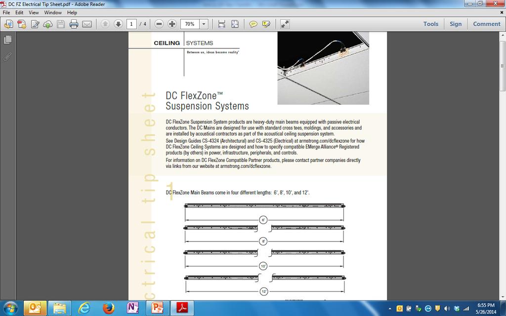
22 Grid Bus Rail Ceiling System Busbar Support One Circuit Busbar Two Circuit Busbar
23

24 Cross Sectional of Two Circuit Grid Bus Rail

25 Cross Sectional of One Circuit Grid Bus Rail The Association of Electrical and

26 Proper placement of Suspension wires

27 Connectors (Load, Feed, Rail to Rail, Pendant)
28 Cable and Connectors EMerge Alliance Registered UL2577 ANSI/NFPA 70 Previously Tyco Electronics


29 Two Circuit Main Beam Populated with Feed, Fixture clip, Device Cable Bottom Device connector

30 Power Feed Connector

31 Bottom Connector 30 Ft limitation on length for power feed #12 AWG Top Connector Device Cables 10 Ft 18 AWG Power feed keyed on Connector, Device connectors not keyed Devices may or may not be Polarity sensitive, Flip device connector!
32 (B) Insulated Conductors. Exposed insulated secondary circuit conductors shall be listed, of the type, and installed as described as follows: (1) Class 2 cable supplied by a listed Class 2 power source and installed in accordance with Parts I and III of Article 725 (2) Wiring methods described in Chapter 3
33 (A&B) Installation Installation Requirements Multiple Trades Division 9 -- Division Building Materials Electrical CSI Architects / Designers Construction Specification Index Construction Specifications Institute (CSI)

34 Installation. (A) General Requirements. Support wiring shall be installed in a neat and workmanlike manner. Cables and conductors installed exposed on the surface of ceilings and sidewalls shall be supported by the building structure in such a manner that the cable is not damaged by normal building use. Such cables shall be supported by straps, staples, hangers, cable ties, or similar fittings designed and installed so as not to damage the cable. Informational Note: Suspended ceiling low-voltage power grid distribution systems should be installed by qualified persons in accordance with the manufacturer s installation instructions.

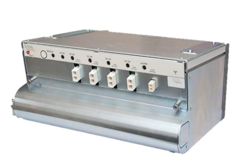
35 Power Supplies
36 Wiring Methods on Supply Side of the Class 2 or Class 3 Power Source Conductors and equipment on the supply side of the power source shall be installed in accordance with the appropriate requirements of Chapters 1 through 4. Transformers or other devices supplied from electric light or power circuits shall be protected by an overcurrent device rated not over 20 amperes. Exception: The input leads of a transformer or other power source supplying Class 2 and Class 3 circuits shall be permitted to be smaller than 14 AWG, but not smaller than 18 AWG if they are not over 12 in. (305 mm) long and if they have insulation that complies with (B) Wiring Methods and Materials on Load Side of the Class 2 or Class 3 Power Source Class 2 and Class 3 circuits on the load side of the power source shall be permitted to be installed using wiring methods and materials in accordance with either (A) or (B). (B) Class 2 and Class 3 Wiring Methods. Conductors on the load side of the power source shall be insulated at not less than the requirements of and shall be installed in accordance with and cable types and listings (cmp,cmr,cmx) Exception No. 1: As provided for in for elevators and similar equipment. Exception No. 2: Other wiring methods and materials installed in accordance with the requirements of shall be permitted to extend or replace the conductors and cables described in and permitted by (B). Exception No. 3: Bare Class 2 conductors shall be permitted as part of a listed intrusion protection system where installed in accordance with the listing instructions for the system.
37

38 Article 725 (Chapter 9 Table)
39 DC instead of AC due to Wiring method exposed in DC circuits
40 Disconnecting Means. (A) Location. A disconnecting means for the Class 2 supply to the power grid system shall be located so as to be accessible and within sight of the Class 2 power source for servicing or maintenance of the grid system. (B) Multiwire Branch Circuits. Where connected to a multiwire branch circuit, the disconnecting means shall simultaneously disconnect all the supply conductors, including the grounded conductors. PS PS
41 (C) Reverse Polarity (Backfeed) Protection of Direct- Current Systems. A suspended ceiling low-voltage power distribution system shall be permitted to have reverse polarity (backfeed) protection of dc circuits by one of the following means: (1) If the power supply is provided as part of the system, the power supply is provided with reverse polarity (backfeed) protection; or (2) If the power supply is not provided as part of the system, reverse polarity or backfeed protection can be provided as part of the grid rail busbar or as a part of the power feed connector
42 Grounding Power Supply feed from a grounded system and equipment grounding/bonding as per 250 Load Side of Supply Shall not be grounded


43 Integration of other DC Power Systems Wind, PV, Batteries, EV Interactive systems, Stand alone systems or Grid interactive, ESS
44 Input to Grid Distribution PV Article Art 690 Fuel Cells Art 692 Wind systems Art 694 Batteries Art 480 Others?
45 Grid Distribution Systems Energy Code requirements Square Foot loading IECC.9W/ Ft² NEC 3VA/ Ft² Lighting Load Calculations

46 Energy Monitoring Article Reducing Service Rating Software to monitor Power supplies Exception: Where the building is designed and constructed to comply with an energy code adopted by the local authority, the lighting load shall be permitted to be calculated at the values specified in the energy code where the following conditions are met: (1) A power monitoring system is installed that will provide continuous information regarding the total general lighting load of the building. (2) The power monitoring system will be set with alarm values to alert the building owner or manager if the lighting load exceeds the values set by the energy code. (3) The demand factors specified in are not applied to the general lighting load.


47 Basic Control Communications Favors an open protocol fringe System Layer Fringe Building Automation Open Local Controllers Supervisory Hybrid ZigBee - Wireless PLC Wired Other Proprietary Control Proprietary Equipment Embedded Control/Sensor Local Controls & Gateways Exclusivity System Local Device Protocol 47 BACnet LonWorks ModBus Other Proprietary


48 DC Products Lighting

49 To see the different products integrated into the Grid System /RegisteredProducts.aspx
50 Future???? What would Benjamin Franklin Say NOW? Thank you for your time
Introducing Low Voltage DC Grid Interconnects
 Introducing Low Voltage DC Grid Interconnects LVDC Grid Interconnects KEY FEATURES Power Feed Cable Assembly Power Feed Connectors are available upon special request comprising of the following: - Universal
NEC 2017 Changes and Their Effect Upon the ICT Industry
 NEC 2017 Changes and Their Effect Upon the ICT Industry Today s Presenters John Kacperski, RCDD, OSP, CDT Chair of BICSI Standards BICSI Representative on NFPA 70-CMP 16 Richard S. Anderson, RCDD, CDT,
ELECTRIC and NEON SIGN STANDARDS. By Randy Wright RKW CONSULTING
 SEMINAR 301 Part 1: Changes in the 2005 NEC SEMINAR RULES: There are no Rules All Questions need to be asked Stop at any time for an explanation SEMINAR PARTS: ELECTRIC and NEON SIGN STANDARDS By Randy
National Fire Protection Association. 1 Batterymarch Park, Quincy, MA Phone: Fax:
 National Fire Protection Association 1 Batterymarch Park, Quincy, MA 02169-7471 Phone: 617-770-3000 Fax: 617-770-0700 www.nfpa.org M E M O R A N D U M TO: Members of Code Making Panel 18 FROM: Jean O Connor
Oberon s National Electric Code (NEC)Compliance Statement and Underwriters Laboratories (UL ) Considerations for Oberon Products
Compliance Statement and Underwriters Laboratories (UL ) Considerations for Oberon Products") Oberon s National Electric Code (NEC)Compliance Statement and Underwriters Laboratories (UL ) Considerations for Oberon Products Manufacturers Statement of Compliance with NFPA 70, National Electric Code,
Oberon s National Electric Code (NEC)Compliance Statement and Underwriters Laboratories (UL ) Considerations for Oberon Products Manufacturers Statement of Compliance with NFPA 70, National Electric Code,
NATIONAL ELECTRICAL CODE (NEC) & NFPA 70E ARC FLASH ELECTRICAL SAFETY
 & NFPA 70E ARC FLASH ELECTRICAL SAFETY") A new twist on the National Electrical Code - a practical application workshop. If you sign up in this class, prepare to work! Day 1: Fundamentals of OSHA requirements for performing electrical work -
A new twist on the National Electrical Code - a practical application workshop. If you sign up in this class, prepare to work! Day 1: Fundamentals of OSHA requirements for performing electrical work -
Oberon s NEC Compliance Statement and Underwriters Laboratories (UL ) Considerations for Oberon Products
 Considerations for Oberon Products") Oberon s NEC Compliance Statement and Underwriters Laboratories (UL ) Considerations for Oberon Products Manufacturers Statement of Compliance with NFPA 70, National Electric Code Oberon s suspended ceiling
Oberon s NEC Compliance Statement and Underwriters Laboratories (UL ) Considerations for Oberon Products Manufacturers Statement of Compliance with NFPA 70, National Electric Code Oberon s suspended ceiling
TABLE OF CONTENTS CHAPTER 1 GENERAL RULES CHAPTER 2 WIRING AND PROTECTION... 51
 TABLE OF CONTENTS About This Textbook...xi How to Use the National Electrical Code... 1 Article 90 Introduction to the National Electrical Code... 7 90.1 Purpose of the NEC... 7 90.2 Scope of the NEC...
Photovoltaic (Solar) Array Installation Guide
 Array Installation Guide") Building & Safety Division Community Development Department 7351 Rosanna Street, Gilroy, CA 95020 Phone: 408 846-0451 Fax: 408 846-0429 Visit us: www.cityofgilroy.org Photovoltaic (Solar) Array Installation
Building & Safety Division Community Development Department 7351 Rosanna Street, Gilroy, CA 95020 Phone: 408 846-0451 Fax: 408 846-0429 Visit us: www.cityofgilroy.org Photovoltaic (Solar) Array Installation
Fire Alarm Systems ARTICLE. Introduction to Article 760 Fire Alarm Systems. Part I. General
 ARTICLE 760 Fire Alarm Systems Introduction to Article 760 Fire Alarm Systems Article 760 covers the installation of wiring and equipment for fire alarm systems, including all circuits controlled and powered
Labeling to Article 690 of the National Electrical Code Routing and Protecting PV Cables
 Labeling to Article 690 of the National Electrical Code Routing and Protecting PV Cables Article 690 labeling requirements from the NEC 2011 Edition General overview of industry labeling Labeling updates
Informational Bulletin on Mobile office Units Prepared by Mark Hilbert May 17, 2017
 Informational Bulletin on Mobile office Units Prepared by Mark Hilbert May 17, 2017 It has come to the attention of the electrical authorities having jurisdiction (AHJs) at the DOE sites there is inconsistency
SECTION 2 NEC REFERENCES SECTION 1 LOW-VOLTAGE AND POWER- LIMITED SYSTEMS...1. CHAPTER 1 GENERAL Introduction...35
 SECTION 1 LOW-VOLTAGE AND POWER- LIMITED SYSTEMS...1 Overview of Low-Voltage and Power-Limited Systems...3 Chapter 4 Equipment for General Use...3 Chapter 5 Special Occupancies...3 Chapter 6 Special Equipment...4
Chapter 1 General... 5
 About This Textbook...xi About the National Electrical Code...xv About the Authors and Illustrator...xix About the Team...xxi Article 90 Introduction to the National Electrical Code... 1 90.1 Purpose of
Update all extract references to NFPA documents (including NFPA 72) in Chapter 3 and related annex material to the latest editions.
 in Chapter 3 and related annex material to the latest editions.") 11/16/12 TerraView First Revision No. 15-NFPA 720-2012 [ Global Input ] Update all extract references to NFPA documents (including NFPA 72) in Chapter 3 and related annex material to the latest editions.
11/16/12 TerraView First Revision No. 15-NFPA 720-2012 [ Global Input ] Update all extract references to NFPA documents (including NFPA 72) in Chapter 3 and related annex material to the latest editions.
Overview of Significant 2017 NEC Changes
 Overview of Significant 2017 NEC Changes National Fire Protection Association. All rights reserved. Five New NEC Articles Article 426 Fixed Resistance and Electrode Industrial Heating Equipment Article
TABLE OF CONTENTS CHAPTER 5 SPECIAL OCCUPANCIES CHAPTER 1 GENERAL RULES... 19
 TABLE OF CONTENTS About This Textbook...xiii How to Use the National Electrical Code... 1 Article 90 Introduction to the National Electrical Code... 7 90.1 Purpose of the NEC... 7 90.2 Scope of the NEC...
NEC Requirements for Standby Power Systems. New England Building Officials Education Association Annual Conference October 5, 2015
 NEC Requirements for Standby Power Systems New England Building Officials Education Association Annual Conference October 5, 2015 Emergency & Standby Power Systems Alternative power sources are utilized
Chapter 1 General...9 Article 100 Definitions...11 Article 100 Questions Article 110 Requirements for Electrical Installations...
 Article 90 Introduction...1 90.1 Purpose of the NEC...1 90.2 Scope of the NEC...2 90.3 Code Arrangement...4 90.4 Enforcement...5 90.5 Mandatory Requirements and Explanatory Material...6 90.6 Formal Interpretations...6
IMPORTANT NOTICE BUILDERS AND CONTRACTORS WORKING IN NORTH RICHLAND HILLS, TEXAS. June 17th, 2016
 IMPORTANT NOTICE BUILDERS AND CONTRACTORS WORKING IN NORTH RICHLAND HILLS, TEXAS June 17th, 2016 RE: City Council Adopts 2014 National Electrical Code with Pool Alarm Requirements On April 25th, 2016 the
WIRING AND PROTECTION
 5997ch02.qxd_mg_cc 4/6/05 12:42 PM Page 5 2 WIRING AND PROTECTION (Excerpts from Chapter 2) 210.1 Scope ARTICLE 210 BRANCH CIRCUITS I. General Provisions Article 210 applies to all branch circuits except
SECTION GENERATOR PARALLELING CONTROLS
 PART 1 - GENERAL 1.1 DESCRIPTION SECTION 26 23 13 GENERATOR PARALLELING CONTROLS SPEC WRITER NOTE: Delete between // -- // if not applicable to project. Also delete any other item or paragraph not applicable
Revisions for the 2011 National Electrical Code - Part 4
 PDHonline Course E358 (3 PDH) Revisions for the 2011 National Electrical Code - Part 4 Instructor: Patrick Ouillette 2012 PDH Online PDH Center 5272 Meadow Estates Drive Fairfax, VA 22030-6658 Phone &
2017 NEC: Impact to Electrical System Designs
 2017 NEC: Impact to Electrical System Designs We will begin shortly. Turn up your speakers in order to hear the hold music. Feel free to ask questions now in the Q&A widget! Today s broadcast is sponsored
SECTION DIGITAL, ADDRESSABLE FIRE-ALARM SYSTEM
 SECTION 283111 - DIGITAL, ADDRESSABLE FIRE-ALARM SYSTEM PART 1 - GENERAL 1.1 RELATED DOCUMENTS A. Drawings and general provisions of the Contract, including General and Supplementary Conditions and Division
CHAPTER 15 PART IV NATIONAL ELECTRICAL CODE, 2017
 CHAPTER 15 PART IV NATIONAL ELECTRICAL CODE, 2017 The City of Portsmouth adopts the State Building Code, which adopts by reference The National Electrical Code, 2017(NEC), as Chapter 15, Part IV, of the
TABLE OF CONTENTS CHAPTER 2 WIRING AND PROTECTION CHAPTER 1 GENERAL RULES... 19
 TABLE OF CONTENTS About This Textbook...xi How to Use the National Electrical Code... 1 Article 90 Introduction to the National Electrical Code... 7 90.1 Purpose of the NEC... 7 90.2 Scope of the NEC...
Electrical Tech Note 107
 Electrical Tech Note 107 Biosystems & Agricultural Engineering Department Michigan State University Understanding the Construction Code Rules, Part 8 1 Based on the 2014 NEC and the 2015 MRC The State
Zurn Pex, Inc. Residential Fire Protection Presentation. PEX Plumbing, Radiant Heating and Residential Fire Protection Systems
 Residential Fire Protection Presentation Zurn Pex, Inc PEX Plumbing, Radiant Heating and Residential Fire Protection Systems Matt Lawrence BDM-North Central Region 1 Presentation Outline I. IRC Mandate
Rocky Mountain Chapter IAEI Annual Meeting Northglenn, CO March 18-19, 2004
 Rocky Mountain Chapter IAEI Annual Meeting Northglenn, CO March 18-19, 2004 1. A 2 PVC conduit was installed in the ground prior to setting a factory manufactured home on the foundation. The required service
SECTION C. Section Cable Trays for Electrical Systems: Additional identification requirements for cable tray systems.
 SECTION 26 0553 PART 1 GENERAL 1.1 SECTION INCLUDES A. Electrical identification requirements. B. Identification nameplates and labels. C. Wire and cable markers. D. Voltage markers. E. Underground warning
DONALD H. BERG, ARCHITECT
 DONALD H. BERG, ARCHITECT DVA PROJECT 632-CSI-402 PET/CT ROOM #A0-10 RENOVATION BASEMENT LEVEL, BUILDING 200 ARCHITECT S PROJECT No. 0917-02 ADDENDUM NO. 1 JUNE 25, 2018 Page 1 of 1 ARCHITECTURAL 1. Specifications:
PowerWave 2 Busway System
 PowerWave 2 Busway System Guide Specifications (Revision 004, 11/17/2017) 1 GENERAL 1.1 Summary This specification covers the electrical characteristics and general requirements for a continuous opening,
APPENDIX - L INTERNATIONAL RESIDENTIAL CODE ELECTRICAL
 This Appendix (2000 IRC Appendix-L) is produced, copyrighted, and maintained by the National Fire Protection Association Association, all rights reserved. Use of this Appendix is pursuant to license with
Electrical Program. Electrical Laws & Rules. Electrical RCW WAC B. Permits Inspections Access Description Directions Comments.
 Electrical Laws & Rules Licensing Electrical Work Scope Administrator Duties Certification Supervision RCW 19.28 WAC 296-46B Permits Inspections Access Description Directions Comments Electrical Program
Title: YALE OFFICE OF FACILITIES PROCEDURE MANUAL Chapter: 01 - Yale Design Standard Division: Electrical Standards
 Change History Date Description of Change Pages / Sections Modified Change Approver Initials 8/1/17 Updated section on Manufacturers 3 1. 6/15/16 Updated division section from 16120 to 26 05 00, - mgl44
M001. Revenue Services ISSUED FOR CONSTRUCTION SEPTEMBER. 2, East State Parkway Schaumburg, Illinois Do Not Scale Drawings
 1 T Consultant: NOTES, SYMBOLS & ABBREVIATIONS - MECHANICAL Number Description M001 Vestibule 117 LAN/IT Coffee 115 116 Mail Room 118 114 113 112 Scanning 119 Open Office 101 FIRST FLOOR PLAN - MECHANICAL
SECTION INTERIOR LIGHTING
 SECTION 26 51 00 INTERIOR LIGHTING PART 1 - GENERAL 1.1 RELATED DOCUMENTS A. Drawings and general provisions of the Contract, including General and Supplementary Conditions and Division 01 Specification
A. Hydraulic calculations shall be prepared in accordance with Chapter 23 of NFPA 13 with the following exceptions:
 SECTION 21 13 13 WET-PIPE FIRE SPRINKLER SYSTEM PART 1 - GENERAL 1.1 RELATED DOCUMENTS: A. The Conditions of the Contract and applicable requirements of Division 1, "General Requirements", and Section
Michigan Chapter IAEI Annual Meeting Ann Arbor, Michigan Code Panel Questions December 5 th and 6 th, 2013
 Michigan Chapter IAEI Annual Meeting Ann Arbor, Michigan Code Panel Questions December 5 th and 6 th, 2013 1. Is a standard wire-nut approved for a wet location as in an outside j-box? Is there a listed
SECTION AUTOMATIC TRANSFER SWITCHES
 PART 1 - GENERAL 1.1 DESCRIPTION SECTION 26 36 23 This section specifies the furnishing, complete installation, and connection of automatic transfer switches. 1.2 RELATED WORK A. Section 14 21 00, ELECTRIC
ORDINANCE NO
 ORDINANCE NO. 2017-08-031 AN ORDINANCE OF THE CITY OF LANCASTER, TEXAS, REPEALING THE NATIONAL ELECTRICAL CODE 2014 EDITION IN ITS ENTIRETY AND REPLACING IT WITH THE ADOPTION OF THE NATIONAL ELECTRICAL
ARTICLE 760 FIRE ALARM SYSTEMS
 Mike Holt s Illustrated Guide to ARTICLE 760 FIRE ALARM SYSTEMS Based on the 2014 NEC Extracted from Mike Holt s Illustrated Guide to Understanding the National Electrical Code Volume 2 For more information
SECTION P01 LIGHTING AND APPLIANCE PANELBOARDS - A-SERIES
 PART 1 GENERAL A. The requirements of the Contract, Division 1, and Division 16 apply to work in this Section. 1.01 SECTION INCLUDES A. Lighting and appliance panelboards 1.02 RELATED SECTIONS A. 16475,
Get it Right the First Time Avoid These Commonly Cited Errors
 May 2014 Get it Right the First Time Avoid These Commonly Cited Errors By Mark Earley and Mark Hilbert Copyright 2014 National Fire Protection Association. All rights reserved. Good electrical contractors
ELECTRICAL - WIRING DESIGN AND PROTECTION SELF INSPECTION CHECKLIST
 Name of School: OPTIONAL INFORMATION Date of Inspection: Vocational Program/Course/Room: Signature of Inspector: ELECTRICAL - WIRING DESIGN AND PROTECTION SELF INSPECTION CHECKLIST Guidelines: This checklist
Revisions for the 2014 National Electrical Code Part 3
 PDH Course E430 Revisions for the 2014 National Electrical Code Part 3 Patrick S. Ouillette, P.E. 2014 PDH Online PDH Center 5272 Meadow Estates Drive Fairfax, VA 22030-6658 Phone & Fax: 703-988-0088 www.pdhonline.org
Division 26 ELECTRICAL TABLE OF CONTENTS
 Division 26 ELECTRICAL TABLE OF CONTENTS 26 1000 GENERAL... 33 A. CODE... 3 B. RELATED SECTIONS... 3 C. ABBREVIATIONS... 3 D. DEFINITIONS... 3 E. DRAWING REQUIREMENTS... 3 F. EQUIPMENT SERVICE ACCESS AND
FireSystem 2000 Commercial and Light Industrial Fire Alarm Control Panel
 PROTECTOWIRE FireSystems Features Easily expandable Two supervised audible circuits Lamp and system trouble circuit test Ground fault detection Initiating device circuit (IDC) alarm test Monitors up to
REPORT ON DISCUSSIONS DURING UL MEETINGS WITH ELECTRICAL INSPECTORS AT THE 2003 IAEI 75 th JUBILEE MEETING
 REPORT ON DISCUSSIONS DURING UL MEETINGS WITH ELECTRICAL INSPECTORS AT THE IAEI 75 th JUBILEE MEETING September 1, 2004 TO: SUBJECT: Attendees of Underwriters Laboratories Inc. Meetings with Electrical
ONYX FirstVision Specification Interactive Firefighters Display
 ONYX FirstVision Specification Interactive Firefighters Display NOTIFIER is a registered trademark, and ONYX FirstVision, NOTI FIRE NET, and VeriFire are trademarks of Honeywell International Inc. Microsoft
isopv and AGH-PV Ground Fault Detector for Ungrounded Solar Arrays up to 1100 V And Isolation Tester Prior to Array Startup (Grounded and Ungrounded)
") T M 1 isopv and AGH-PV Ground Fault Detector for Ungrounded Solar Arrays up to 1100 V And Isolation Tester Prior to Array Startup (Grounded and Ungrounded) Technical Bulletin NAE1012372 / 03.2015 isopv
T M 1 isopv and AGH-PV Ground Fault Detector for Ungrounded Solar Arrays up to 1100 V And Isolation Tester Prior to Array Startup (Grounded and Ungrounded) Technical Bulletin NAE1012372 / 03.2015 isopv
I dedicate this book to the Lord Jesus Christ, my mentor and teacher. Proverbs 16:3 NOTICE TO THE READER ABOUT THE AUTHOR
 NOTICE TO THE READER The publisher does not warrant or guarantee any of the products described herein or perform any independent analysis in connection with any of the product information contained herein.
SECTION LIGHTING CONTROLS
 PART 1 - GENERAL 1.1 DESCRIPTION SECTION 26 09 23 LIGHTING CONTROLS SPEC WRITER NOTE: 1. Delete between //----// if not applicable to project. Also, delete any other item or paragraph not applicable to
CSI Master Format 2004 Guide Specification for: Freezer Frost Heave Prevention (Mineral Insulated)
") CSI Master Format 2004 Guide Specification for: Freezer Frost Heave Prevention (Mineral Insulated) System for preventing frost heave in freezers, cold rooms and ice arenas with temperature control, monitoring,
CSI Master Format 2004 Guide Specification for: Freezer Frost Heave Prevention (Mineral Insulated) System for preventing frost heave in freezers, cold rooms and ice arenas with temperature control, monitoring,
A. Furnish and install luminaires, lamps, ballasts and in-line fuses as herein specified and shown on the Drawings.
 DIVISION 26 ELECTRICAL SECTION 26 51 13 PART 1 GENERAL 1.01 DESCRIPTION A. Furnish and install luminaires, lamps, ballasts and in-line fuses as herein specified and shown on the Drawings. B. Luminaire
PART GENERAL 1.01 SECTION INCLUDES
 Specification Number: 26 24 16.06 Product Name: Emergency Lighting Control NQ Circuit Panelboards: 240 Vac, 48 Vdc Maximum SECTION 26 24 16.06 Emergency Lighting Control NQ Circuit Panelboards: 240 Vac,
National Electrical Code
 National Electrical Code 409.30 Disconnecting Means Disconnecting means that supply motor loads shall comply with Part IX of Article 30. 410.81 Control (A) Disconnection Luminaires (fixtures) or lamp installation
2017 NEC Presented by: Russ LeBlanc
 2017 NEC Presented by: Russ LeBlanc 1. 90.2(A)-installation and removal 2. 90.3-code layout 3. 100-readily accessible 4. 100-field evaluation body (FEB) 5. 100-field labeled 6. 100-receptacle 7. 100-structure
TOM BURNS, PLANNING DIRECTOR
 ~~ 0 173 COUNTY OF SANTA CRUZ August 4,2005 PLANNING DEPARTMENT 701 OCEAN STREET, qth FLOOR, SANTA CRUZ, CA 95060 (831) 454-2580 FAX: (831) 454-2131 TDD: (831) 454-2123 TOM BURNS, PLANNING DIRECTOR Agenda:
EVLPF Series Compact Fluorescent
 EVLPF Series Low Profile Hazard Gard Luminaires Cl. I, Div. 1, Groups B (GB Suffix), C, D Cl. I, Zone 1, Groups IIB + H2 (GB Suffix), IIB, IIA Cl. II, Div. 1, Groups E, F, G Class III, Simultaneous Presence
COMMON WORK RESULTS FOR ELECTRICAL: Basic Electrical Materials Methods
 1. BASIC ELECTRICAL MATERIALS 1. All conduit and raceway must be 3/4" or larger. Exposed raceway in finished areas shall be in 700 or larger wiremold. Exception: runs to individual devices 10 or less,
SECTION PANELBOARDS. A. Drawings and general provisions of the Contract, including General and Supplementary Conditions, apply to this Section.
 PART 1 - GENERAL 1.1 RELATED DOCUMENTS A. Drawings and general provisions of the Contract, including General and Supplementary Conditions, apply to this Section. 1.2 SUMMARY A. This Section includes the
SECTION ISOLATED POWER SYSTEMS
 PART 1 - GENERAL 1.1 DESCRIPTION SECTION 26 20 11 ISOLATED POWER SYSTEMS SPEC WRITER NOTE: Delete between //---// if not applicable to project. Also, delete any other item or paragraph not applicable to
9/7/2010. Chapter , The McGraw-Hill Companies, Inc. AND BONDING. 2010, The McGraw-Hill Companies, Inc.
 Chapter 1 GROUNDING AND BONDING 1 Proper grounding practices protect people from the hazards of electric shock and ensure the correct operation of overcurrent protection devices. Grounding is the intentional
J-PRO TM Cable Support System
 Frequently Asked Questions Cable Support System What references define how and where J-hooks are used? J-hooks are a horizontal pathway promoted in the BICSI TDM manual as a means to route small to medium
UltraLITE Model ELU Centralized Emergency Lighting Inverter 4.2 KW- 5 KW
 12/23/16 Rev 9 UltraLITE Model ELU General Specification 4.2 KW to 5 KW UltraLITE Model ELU Centralized Emergency Lighting Inverter 4.2 KW- 5 KW 1.0 General General Specification This specification describes
SECTION PANELBOARDS Painting Wire and Cable Overcurrent Protective Devices.
 SECTION 16470 PANELBOARDS PART 1 GENERAL 1.01 SUMMARY A. Related Sections: 1. 09900 - Painting. 2. 16120 - Wire and Cable. 3. 16475 - Overcurrent Protective Devices. 1.02 SYSTEM DESCRIPTION A. Performance
Surviving Survivability A User s Guide to Survivable Fire Alarm Circuits Larry D. Rietz, SET 23 May 2018
 Surviving Survivability A User s Guide to Survivable Fire Alarm Circuits Larry D. Rietz, SET 23 May 2018 Automatic FireAlarm Association SURVIVING SURVIVABILITY - A USER S GUIDE TO Larry D. Rietz, SET
Installation Guide for models:
 140 58th St. Brooklyn, NY Access Power Controllers with Power Supplies Installation Guide for models: Maximal3FD - 12VDC @ 4.6 amp or 24VDC @ 5.2 amp. - Sixteen (16) PTC protected power-limited outputs.
Commercial and Light Industrial Fire Alarm Control Panel
 FireSystem 2000 Commercial and Light Industrial Fire Alarm Control Panel Features Easily expandable. All new plug-in board design Two supervised audible circuits Lamp and system trouble circuit test Ground
Bold items are particular to the City of Euless
 EULESS FIRE DEPARTMENT FIRE MARSHAL S OFFICE INFORMATION LINE: Revised 8/2004 Fire Chief Lee Koontz Fire Marshal Paul Smith EFD-FMO 3-1 2003 International Fire & Building Code as Amended NFPA Standards
Smoke detection in hazardous areas:
 WHITE PAPER Smoke detection in hazardous areas: What you need to know Smoke detection in hazardous areas requires detectors that operate effectively and safely in explosive environments. Having the correct
NEW ENERGY IN THE BATTERY INFRASTRUCTURE
 NEW ENERGY IN THE BATTERY INFRASTRUCTURE Maurice H. Johnson Business Development Engineer UL LLC Northbrook, IL Paper Overview Over the past several years, there has been a significant effort to address
B. Configuration of system shall be through Schneider Electric in Homewood, Illinois (Jerry Lanfear ).
.") SECTION 28 13 00 - ACCESS CONTROL PART I - GENERAL 1.1 SUMMARY A. This specification section describes the furnishing, installation, commissioning, and programming of a complete, turnkey, hardwired Andover
SECTION 28 13 00 - ACCESS CONTROL PART I - GENERAL 1.1 SUMMARY A. This specification section describes the furnishing, installation, commissioning, and programming of a complete, turnkey, hardwired Andover
West District Library Section Campeau Drive, Ottawa SPRINKLER SYSTEMS City of Ottawa Project No. CR Page 1 of 8
 City of Ottawa Project No. CR006230 Page 1 of 8 PART 1 - GENERAL 1.1 Reference Standards.1 Conform to the following:.1 Provincial and municipal building and fire regulations as approved by Provincial Fire
SECTION LOW VOLTAGE POWER PANELBOARDS - SPECTRA
 PART 1 GENERAL A. The requirements of the Contract, Division 1, and Division 16 apply to work in this Section. 1.01 SECTION INCLUDES A. Low voltage power panelboards 1.02 RELATED SECTIONS 1.03 REFERENCES
SECTION AUTOMATIC TRANSFER SWITCHES
 PART 1 - GENERAL 1.1 DESCRIPTION SECTION 26 36 23 SPEC WRITER NOTE: Use this section only for NCA projects. Delete between //--// if not applicable to project. Also, delete any other item or paragraph
Chang Liu Lighting + Electrical M.A.E./B.A.E. Integrated Degree. Technical Assignment 2 October 12, 2012 Faculty Consultants: Ron Dodson
 M.A.E./B.A.E. Integrated Degree Technical Assignment 2 October 12, 2012 Faculty Consultants: Ron Dodson Renzo Museum of American Art Executive Summary This report provides an analysis of the electrical
Catalog Number. Notes
 Catalog Number FEATURES & SPECIFICATIONS INTENDED USE Built on the compact, low-profile Z strip channel, this LED strip offers long maintenance-free life, several color s, lumen outputs and lengths. Ideal
SECTION LOW VOLTAGE LIGHTING CONTROLS
 SECTION 26 09 26 LOW VOLTAGE LIGHTING CONTROLS PART 1 - GENERAL 1.01 RELATED DOCUMENTS: A. The Conditions of the Contract and applicable requirements of Division 1, "General Requirements", and Section
A. Furnish and install wiring devices and plates as specified herein and as shown on the Drawings.
 DIVISION 26 ELECTRICAL SECTION 26 27 26 PART 1 GENERAL 1.01 DESCRIPTION A. Furnish and install wiring devices and plates as specified herein and as shown on the Drawings. B. Specialty switches and outlets
Bulletin 1608N MiniDySC Dynamic Sag Corrector
 User Manual Bulletin 1608N MiniDySC Dynamic Sag Corrector Single Phase Voltage Sag Correction 2...6 Amps (250...750 VA) Important User Information Solid-state equipment has operational characteristics
AGENDA. NEC Code-Making Panel 12. Report on Comment Meeting. Dates: November 28 December 1, Redondo Beach, CA
 National Fire Protection Association 1 Batterymarch Park, Quincy, MA 02169-7471 Phone: 617-770-3000 Fax: 617-770-0700 www.nfpa.org AGENDA NEC Code-Making Panel 12 Report on Comment Meeting Dates: November
Industrial Machinery Standards:
 NFPA 79 for the US in comparison to IEC / EN 60204-1 (2016 Edition) Intertek 70 Codman Hill Road Boxborough, MA 01719 www.intertek.com/hazloc 1-800-WORLDLAB icenter@intertek.com Introduction Every year,
Electrical Design Guidelines Table of Contents
 C: Compliant Rev. 3 Dated June 13 11 NC: Non-Compliant NA: Not Applicable Page1 16.1 General 16.2 Single Line Diagrams 16.3 Electric Motor Equipment and Controls 16.4 Lighting 16.5 Emergency Lighting 16.6
Are Open Bottom Electrical Handholes a NEC Violation? Proposals to Change the 2002 NEC Traffic Signal and Roadway Lighting Related
 Are Open Bottom Electrical Handholes a NEC Violation? Proposals to Change the 2002 NEC Traffic Signal and Roadway Lighting Related Introduction One of the proposals to change the 2002 NEC adds a provision
University of Houston Master Construction Specifications Insert Project Name SECTION DRY-PIPE FIRE SPRINKLER SYSTEM PART 1 - GENERAL
 SECTION 21 13 16 DRY-PIPE FIRE SPRINKLER SYSTEM PART 1 - GENERAL 1.1 RELATED DOCUMENTS: A. The Conditions of the Contract and applicable requirements of Division 1, "General Requirements", and Section
INSTALLATION INSTRUCTIONS
 INSTALLATION INSTRUCTIONS Flow Lighting QuickLED NEW FIXTURE 2x4 2x2 1x4 Corporate 1240 Texan Trail, Suite 102 Grapevine, TX 76051 (817)435-8484 Office www.flowledlighting.com READ AND FOLLOW ALL SAFETY
Second Revision No. 601 NFPA [ Section No [Excluding
 Second Revision No. 601 NFPA 70 2015 [ Section No. 300.4 [Excluding any Sub Sections] ] Where subject to physical damage, conductors, raceways, and cables shall be protected. Informational Note: Minor
2011 and 2014 National Electrical Code Changes Residential Only
 2011 and 2014 National Electrical Code Changes Residential Only Sponsored By: and.net Instructor: Fritz Gunther, Chief Electrical Inspector 585-436-4460 www.nyeia.com NEW YORK ELECTRICAL INSPECTION AGENCY
NCEHSA Conference. Carbon Monoxide Detector Regulations for Lodging Establishments (S.L )
") NCEHSA Conference Carbon Monoxide Detector Regulations for Lodging Establishments (S.L. 2013-413) 1 Purpose of this session The purpose of this session is to review the provisions of Session Law 2013-413
NCEHSA Conference Carbon Monoxide Detector Regulations for Lodging Establishments (S.L. 2013-413) 1 Purpose of this session The purpose of this session is to review the provisions of Session Law 2013-413
Catalog Number. Notes. Type. FST Snap on frosted, diffuse L/LENS No diffuser
 Catalog Number FEATURES & SPECIFICATIONS INTENDED USE Built on the compact, low-profile Z strip channel, this LED strip offers long maintenance-free life, several color s, lumen outputs and lengths. Ideal
TABLE 1-E (2017) Effective July 1, 2017
 Effective July 1, 2017") TABLE 1-E (2017) Effective July 1, 2017 Oregon Amendments to the 2017edition of the National Fire Protection Association (NFPA) 70, National Electrical Code (NEC) for the 2017 Oregon Electrical Specialty
TABLE 1-E (2017) Effective July 1, 2017 Oregon Amendments to the 2017edition of the National Fire Protection Association (NFPA) 70, National Electrical Code (NEC) for the 2017 Oregon Electrical Specialty
Alberta Municipal Affairs
 Alberta Municipal Affairs Upcoming Already Approved by Unanimous Vote Not Required to be Considered in Charlottetown in June Clarence C. Cormier, P.Eng. Chief Electrical Inspector Bob Hall, SCO Electrical
2017 NEC Significant Code Changes Part 3
 2017 NEC Significant Code Changes Part 3 Eight (8) Continuing Education Hours Wisconsin Department of Safety and Professional Services (DSPS) Course Approval #18959 Approved Continuing Education for Wisconsin
Submittal Data PERFORMANCE DATA CERTIFIED DIMENSION PRINTS CERTIFIED ROOF CURB DIMENSION PRINTS SERVICE OPTION DIMENSION PRINTS
 Single Package Rooftop Gas Heating/Electric Cooling Unit Two Stage Cooling Capacity Control with Puronr (R---410A) Refrigerant Sizes: 17, 20, 24, 28, 30 Submittal Data PERFORMANCE DATA CERTIFIED DIMENSION
SECTION SOLAR PHOTOVOLTAIC (PV) POWER GENERATION SYSTEM
 POWER GENERATION SYSTEM") SECTION 48 14 14 SOLAR PHOTOVOLTAIC (PV) POWER GENERATION SYSTEM PART 1 GENERAL 1.1 SECTION INCLUDES The work of this section consists of furnishing a complete Solar Photovoltaic (PV) Power Generation
SECTION 48 14 14 SOLAR PHOTOVOLTAIC (PV) POWER GENERATION SYSTEM PART 1 GENERAL 1.1 SECTION INCLUDES The work of this section consists of furnishing a complete Solar Photovoltaic (PV) Power Generation
A. This Section includes the following lighting control devices:
 Attachment G LIGHTING CONTROL SPECIFICATIONS (Download Document separately) LIGHTING CONTROL SPECIFICATIONS PART 1 - GENERAL 1.1 RELATED DOCUMENTS A. Drawings and general provisions of the Contract, including
IEC and NCCER Mapping for Year 1
 Craft: 26102-14 Safety IEC and NCCER Mapping for Year 1 Perform a visual inspection on various types of ladders 102.4 STATE GENERAL SAFETY CONSIDERATIONS IN ELECTRICAL INSTALLATIONS (LADDER SAFETY, SLECTION