Technical Handbook
|
|
|
- Joanna Harrington
- 6 years ago
- Views:
Transcription


1 Technical Handbook Smart heat for comfort and safety

2 Smart heat for comfort and safety As the world leader in heat-tracing systems, Tyco Thermal Controls has the system that you need from pipe-freezing prevention or maintaining fluid temperatures, to melting snow and heating floors. After 35 years with unrivalled versatility and smart systems, Raychem s self-regulating cable technology still remains at the forefront in heat-tracing solutions. For commercial or residential applications, new construction or renovation, our smart solutions will perform perfectly for greater comfort and safety. The heart of our solutions In 1970, Raychem first developed and launched self-regulating electric heating cables. The cable delivers the right amount of heat exactly when and where it is needed. As the temperature drops, more heat is produced. Conversely, as the temperature rises, less heat is produced. But there are many more benefits: The smart cables can be overlapped without any risk of overheating. The heating cables can be cut to length in the field. This means additional flexibility when plans do not correspond to the real life situation on site. The length of pipe corresponds to the length of cable that you need. A B C Tested and qualified Stringent production monitoring Approved BS EN (IEC 60800) VDE approved CE marked A Cold ambient = High power output If the temperature in the immediate vicinity of the self-regulating heating cable is cold, the heat output from the heating cable is increased. The polymeric core of the cable contracts, which creates many electrical paths across the integrated carbon particles. B Warm ambient = Low power output In response to a warmer environment, the heat output of the self-regulating cable is reduced. The polymeric core of the cable expands, reducing the electrical paths. C Hot ambient = Virtually no output If the temperature in the environment of the self-regulating heating cable reaches a high temperature, the heat output is minimal. Due to the maximum expansion of the polymeric core of the cable, most of the electrical paths are broken. Member of the European Radiant Floor Heating Association e.v. Our products satisfy the requirements of the relevant European Directives. Robust construction Long service life assured through modified polyolefin or fluorpolymer insulation and jacket materials. Life time Intensive tests according to recognized scientific procedures. Results: self-regulating heating cables have a service life in excess of 20 years. 2 Technical handbook

 are designed for easy set-up and operation. They are easy to access for fast wiring.")


3 Raychem Smart Services It s not only the cable! The combination of a self-regulating heating cable and a smart control unit allows for dynamic management of the heating cable s power output dependent on parameters such as ambient temperature and moisture. These will help you and your customers to comply with today s building regulations on energy savings. A complete Raychem system can result in energy savings of up to 80%! Our control units (e.g. HWAT-ECO) are designed for easy set-up and operation. They are easy to access for fast wiring. Ergonomic buttons, intuitive menudriven operation and pre-installed programmes allow for quick set-up. Raychem offers a set of tools and services that aim to simplify the professional s life. Not only do we offer the best quality products, we also support them with unrivalled services. An efficient customer service centre Large technical support team Multi-lingual customer service representatives to answer all your questions Fast order handling & shipment Europe-wide Free documentation service On demand technical advice Free designs and quotations Direct support to specifiers and installers Training support upon request Complete after-sales service Also for non-standard applications our team can assist you in finding the right heating solution. Do not hesitate to get in touch with us. Free phone or Free fax Specific connection systems have been designed and configured to be fully compatible with our heating cables. The RayClic connection system cuts installation time by 80%. Inserting the stripped cable into the module and tightening a few screws is all it takes. Tyco Thermal Controls is also a proud industry supporter offering approved CPD courses via the Chartered Institute of Building Services Engineers. Courses include technical and application information for electrical underfloor heating and hot water temperature maintenance systems. For further information, please consult the CIBSE Course Directory 2010 or contact Tyco Thermal Controls. Our website provides you with all information from product selection to downloadable installation manuals. Technical handbook 3


4 Overview of applications Technical handbook CDE-0517 Rev.8 06/10


5 1 Hot water temperature maintenance 6 Hot water temperature maintenance 2 Frost protection for pipes 16 Frost protection for pipes 3 Frost protection for gutters and downpipes 37 Frost protection for gutters and downpipes 4 Snowmelting of ramps, steps, footpaths and accessways 46 Snowmelting of ramps, steps and footpaths 5 Electrical underfloor heating 49 Electrical underfloor heating General installation instructions for self-regulating heat-tracing systems General installation instructions Technical data Choice of accessories 58 CDE-0517 Rev.8 06/10 Technical handbook 5

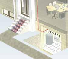
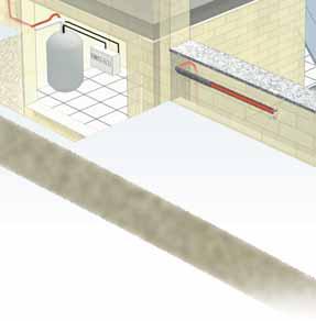
6 Hot water temperature maintenance Hot water temperature maintenance Providing the comfort of instant hot water is the key requirement of any modern hot water system. The Raychem single-pipe system keeps water at the right temperature in a building s water distribution pipe work. The intelligent system first keeps the investment cost low and then it operates economically and efficiently. An hygienic system Less water volume and less heat loss in the pipe work help prevent bacteriological problems. A flexible and space-saving system The space requirement for pipes has been reduced because there are no return pipes. Risers, shafts and openings can be optimised freeing space for other services. Low investment costs The heating cable is simply fixed on the supply pipe. There is no need for return pipe work, valves or pumps, nor for complex design and balancing work associated with return systems. Lower power consumption The heat loss in the system is significantly lower as only the heat loss from the feed pipe (and not from the return pipe) is to be compensated for. There is also no power requirement for circulation pumps. The single-pipe system can be used with a smaller boiler and as there is no cold return water coming into the boiler, the heat-up of the water is more efficient. The intelligent HWAT-ECO control unit saves power e.g. it can lower the temperature or switch off during water consumption peaks. No maintenance costs The system has no mechanical parts such as a recirculation pump or control valves. There are no parts to wear out. Gel-filled end seal (RayClic-E-02) Heating cable (HWAT-L, M or R) 4-way connection (RayClic-X-02) Power connection (RayClic-CE-02) Sensor HWAT-ECO (incl.) A three-wire PT-100 temperature sensor (HARD-78) can be installed optionally in an immersion pipe installed on site. Residual current device (rcd) (30 ma) Circuit-breaker (C type) Temperature control unit (HWAT-ECO) 6 Technical handbook CDE-0517 Rev.8 06/10
7 Design guide, control units and accessories 1. Heating cable selection Optimum water temperature maintenance for single family houses, flats, offices, hotels, hospitals, convalescent homes, sports centres,... Heating cable type HWAT-L HWAT-M HWAT-R Power output 7W/m at 45 C 9 W/m at 55 C 12 W/m at 70 C Max. exposure temperature 65 C 65 C 80 C Outer jacket colour yellow orange red Control unit HWAT-ECO recommended for essential enhanced energy - efficiency Legionella prevention Possibility of thermal legionella prevention up to the draw-off points Hot water temperature maintenance 2. Composition of the HWAT-L/M/R heating cable Copper conductor (1.2 mm 2 ) 2 Self-regulating heating element 3 Modified polyolefin insulation 4 Aluminium foil wrap 5 Protective tinned copper braid 6 Modified polyolefin protective outer jacket Technical data: see page Heating cable length The heating cable is installed in a straight line on the pipework The heating cable can be traced right up to the draw-off points Total length of pipe to be traced + approx. 0.3 m per connection + approx. 1.0 m per T-connection + approx. 1.2 m per 4-way connection = required heating cable length 4. Insulation thicknesses Pipe size (mm) Insulation thickness (mm) Ambient temperature: 18 C Thermal conductivity λ = W/(m.K) For other thermal conductivity insulation materials, contact your Tyco Thermal Controls representative. 5. Electrical protection The total length of heating cable determines the number and size of the circuit breakers Residual current device (rcd) : 30 ma required Power cabling for the heating cables according to local regulations The power connection must be carried out by an approved electrical installer Circuit-breaker to BSEN (type C) : the maximum length of the heating circuit is based on a minimum start-up temperature of +12 C, 230 VAC. HWAT-L HWAT-M HWAT-R 10 A 80 m 50 m 50 m 13 A 110 m 65 m 65 m 16 A 140 m 80 m 80 m 20 A 180 m 100 m 100 m CDE-0517 Rev.8 06/10 Technical handbook 7
8 Hot water temperature maintenance Hot water temperature maintenance 6. Checklist for planning the installation The system design should take into account: Pipe diameter and material Insulation type and thickness Ambient temperature Circuits should divide the plumbing into logical segments Don t exceed the maximum circuit length Show connection locations on the drawings Locate power connections near the electrical panel Locate T-connections in accessible areas 7. Testing of the installation See page Control units HWAT-ECO Electronic temperature control unit with integrated clock Building-specific programme Boiler temperature monitoring Economy programmes Password protection Simple user interface Compatible with HWAT-L/M/R heating cables BMS interface Alarm outputs Technical data: see page 11 HARD Accessories RayClic-CE-02 RayClic-T-02 PT-100 temperature sensor (HARD-78) for assembly in sensor pipe installed on site. Diameter of sensor cable 4 mm Diameter of sensor element 6 mm Length of sensor element 50 mm Sensor length total 3 m Power connection With 1.5 m power cable End seal and support bracket IP 68 External dimension: L = 240 mm W = 64 mm H = 47 mm T-connection Connection for 3 cables End seal and support bracket IP 68 External dimension: L = 270 mm W = 105 mm H = 42 mm 8 Technical handbook CDE-0517 Rev.8 06/10
9 RayClic-PT-02 RayClic-S-02 RayClic-PS-02 RayClic-X-02 Power T-connection 3 connections with integral 1.5 m power cable 3 end seals and 1 support bracket IP 68 External dimension: L = 270 mm W = 105 mm H = 42mm Splice for joining 2 lengths of heating cable Connection for 2 cables with 1 support bracket IP 68 External dimension: L = 240 mm W = 64 mm H = 47 mm Powered splice Connection for 2 cables with integral 1.5 m power cable 2 end seals and 1 support bracket IP 68 External dimension: L = 270 mm W = 105 mm H = 42 m 4-way connection Connection for 4 cables 2 end seals and 1 support bracket IP 68 External dimension: L = 270 mm W = 105 mm H = 42 mm Hot water temperature maintenance RayClic-E-02 RayClic-LE-02 KBL-10 Gel-filled end seal For system extensions (to be ordered separately) IP 68 RayClic with illuminated end seal For visual representation of voltage (by green lamp) 1 retaining bracket IP 68 External dimension: L = 240 mm W = 64 mm H = 47 mm Cable ties One pack of 100 required for approx. 30 m of pipework Length: 370 mm Temperature and UV resistant Use ATE-180 on plastic pipes CDE-0517 Rev.8 06/10 Technical handbook 9
10 Hot water temperature maintenance Hot water temperature maintenance GT-66 Heat-resistant glass cloth tape For steel pipes or for any installation below 4.4 C 20 m roll for approx. 20 m of pipework Use ATE-180 on plastic pipes GS-54 Glass cloth tape for attaching heating cable to pipe For stainless-steel pipes or for any installation below 4.4 C 16 m per roll, 12 mm width ATE-180 Aluminium adhesive tape Heat resistant up to 150 C 55 m roll for approx. 50 m of pipework On plastic pipes: the heating cable must be covered with aluminium adhesive tape along its entire length IEK-20-M (for HWAT-L, -M) /IEK (for HWAT-R) Insulation entry kit Insertion of heating cable in metal cladding Consists of: metal fasteners, metric gland and joint seal LAB-I-01 ELECTRIC TRACED R Electric traced label To be placed at 5 m intervals on insulation surface 10. General installation See page 55 instruction 10 Technical handbook CDE-0517 Rev.8 06/10
11 HWAT-ECO Temperature control unit Module layout A B C D E A Power supply on (green LED) B Power to heater on (green LED) C Legionella prevention (green LED) - heating cable 100% powered - increased risk of scalding D Maintain temperature lowered following boiler temperature decrease (green LED) - boiler temperature is lower than expected. E Error (red LED) Hot water temperature maintenance Change menu selection or position cursor Escape, backspace or NO Confirm selection, new value or YES Technical data Product description HWAT-ECO 165 Use Only for HWAT-L/M/R heating cables Selectable maintain temperature 37 C to 65 C in max. 48 timer blocs per day Operating voltage 230 VAC (+10%, 10%), 50 Hz 85 Switching capacity 20 A / AC 230V Internal power consumption 2,5 VA Circuit breaker Max. 20 A, C-Characteristic Power cable section entry mm 2 for fixed wiring only Auxiliary cable section entry Up to 16 AWG (1.3 mm 2 ) Weight 880 g Mounting options Wall mount with 2 screws or DIN rail 70 Cable glands (entries) 2 x M20 and 1 x PG13.5 with 3 inputs for external wires of 3-5 mm Protection level IP 54 Ambient temperature 0 C to 40 C 85 Housing material ABS Internal temperature alarm 85 C Master/slave cable 2-wire twisted pair shielded, max. 1.3 mm 2 core and insulation of 500 V Master/Slave Master is selectable in the unit, up to 8 slaves can be con nect ed BMS interface 0-10 VDC (Dimensions in mm) Alarm relay contacts Max. 24VDC or 24 VAC, 1 A, SPDT voltage free Boiler temperature sensor PTC KTY or PT wire Power correction factor 60% to 140% (fine tuning of maintained temperature) Clock back-up time Min. 1 year with lithium battery CR2025 (3V) Clock accuracy ±10 minutes per year Real time clock Automatic summer/winter time and leap year correction Parameters stored in non-volatile All parameters, except date and time memory Approval VDE according to EN EMC According to EN /2 for emission and EN /2 for immunity Raychem requires the use of a 30 ma residual current device and a C-Characteristic circuit breaker to provide maximum safety and protection from fire. The unit complies with IEC (flicker) if installed according to part 3 of VDE To avoid flicker install the unit in such a way that at the current value of the systems start-up temperature (max. 20 A per heating circuit) the voltage drop does not exceed 1% at the power supply of the lighting apparatus (normally subpanel). CDE-0517 Rev.8 06/10 Technical handbook 11
12 Hot water temperature maintenance Hot water temperature maintenance Programme The HWAT-ECO has 7 different building specific time/temperature programmes. These programmes are based on our long experience for optimum comfort and energy saving. For user specific changes in the programming, the Edit timer programme can be used. Programme name Programme 0 Programme 1 Programme 2 Programme 3 Programme 4 Programme 5 Programme 6 Building type Constant temperature (±55 C) Apartment block Prison / Barracks Hospital Hotel Sports centre / Swimming pool Office In addition, user specific programmes can be created Temperature can be varied in 1/2 h blocks to any desired temperature between: OFF, economy t, maintain t and legionella prevention (100% powered, increased risk of scalding) 12 Technical handbook CDE-0517 Rev.8 06/10
13 Wiring diagram for HWAT-L / HWAT-M / HWAT-R with HWAT-ECO temperature control unit L1 L2 L3 N * Hot water temperature maintenance ** cable type RS-485, 2-pole contact **** *** Optional PE BMS L N B A HWAT-ECO TEMP L N PE BMS L N B A HWAT-ECO TEMP L N PE Alarm Alarm Alarm BMS L N B A HWAT-ECO TEMP L N PE Self-regulating heating cable Temperature sensor Self-regulating heating cable Self-regulating heating cable * Two- or four-pole electrical protection by circuit breaker may be needed for local circumstances, standards and regulations ** Depending on the application, one- or three-pole circuit-breakers or contactors may be used *** Optional: Potential-free circuit-breaker for connection to the BMS **** The earth wire of shielded RS-485 cable needs to be connected to the BMS (-) terminal of each HWAT-ECO in the Master / Slave network. CDE-0517 Rev.8 06/10 Technical handbook 13
14 Hot water temperature maintenance Hot water temperature maintenance 11. Installation instructions for HWAT-L/M/R cables The heating cable should be installed in a straight line on the pipework. Install on dry surfaces Minimum installation temperature: 10 C ca. 45 ca. 45 horizontal pipes max. 300 mm Horizontal pipevertical pipe Cable tie KBL-10 For plastic pipes use aluminium adhesive tape ATE-180. Place it over the entire length of the pipe GT-66 / GS-54 adhesive tape Cut the heating cable at right angles Smallest bending radius: 10 mm It is not necessary to spiral the cable around the pipe 90 Install the heating cables on the outside of the pipe bend Installation of self-regulating heating cables Store in a dry and clean place. Temperature range: 40 C to +60 C. Protect any cable ends with an end seal. Avoid: sharp edges high tractive force kinking and crushing walking or driving over the cable moisture at cable interfaces 14 Technical handbook CDE-0517 Rev.8 06/10
15 Standard Installation of PT100 Sensor with in-pipe sensor probe. MASTER Hot water temperature maintenance HWAT RayClic L N 230V Run the cable over pipe suspensions Do not clamp the cable PT100 sensor probe installed within the hot water supply pipe work. Wall/Floor transit The thickness of thermal insulation must be continuous otherwise compensate by adding heating cable. 3 m HWAT-L 3 m 3 m HWAT-M and HWAT-R 3 m insulation > 3m + Rayclic > 3 m RayClic RayClic-T-connection Electric traced label IEK-20-M / IEK for insertion of heating cable in metal cladding CDE-0517 Rev.8 06/10 Technical handbook 15

16 Frost protection for pipes Frost protection for pipes Frozen pipes can be a costly problem. When pipes are exposed to subzero temperatures they can burst, leading to considerable damage and disruption. The Raychem frost protection system for pipes provides an efficient solution. The selfregulating heating cable, combined with an adequate insulation, prevents water pipes, fire mains, sprinkler systems and fuel oil lines from freezing. Thermostat with line or ambient temperature sensor Residual current device (30 ma) Circuit-breaker (C type) Easy to install The heating cable is simply fixed onto the pipe under the thermal insulation. Connections are quickly made with the fast RayClic connectors. Durable and reliable The cable s large copper conductors make it a reliable solution and its specially formulated outer jacket protects it from severe environmental conditions. Low power consumption The smart RAYSTAT -ECO control unit calculates a duty-cycle proportional to the expected minimum temperature. Where a simple ambient thermostat would energize the heating cable for 100%, the smart controller would energize for a fraction of the time, resulting in significant extra savings. Junction box (JB16-02) T-Connection (RayClic-T-02) (Not for FS-C-2X / ) ) Power connection (RayClic-CE-02) (Not for FS-C-2X / ) Electrical traced label (LAB-I-01) Frost protection heating cable (, FS-B-2X, FS-C-2X or ) End seal (RayClic-E-02) (Not for FS-C-2X / ) 16 Technical handbook CDE-0517 Rev.8 06/10

17 Design guide, control units and accessories 1. Heating cable selection Application Frost protection for pipework at max. 65 C operating temperature 10 W/m at 5 C FS-B-2X 26 W/m at 5 C Frost protection for pipework at max. 95 C operating temperature and temperature maintenance for metal waste pipes with fatty waste water FS-C-2X 31 W/m at 5 C 22 W/m at 40 C Frost Protection for pipework to maximum 90 C operating temperature. For long circuit applications and central heating pipework. 10 W/m at 5 C TraceCalc.Net Construction is a software tool for product selection based on actual project data. Visit < industrial_design/default.aspx> for more information. Frost protection for pipes 2. Composition of the FS-A/B/C/C10-2X heating cable Copper conductor (1.2 mm 2 ) 2 Self-regulating heating element 3 Modified polyolefin insulation (FS-C-2X: Fluoropolymer) 4 Protective tinned copper braid 5 Modified polyolefin protective jacket 4 5 Note: comprises copper conductors (1.4 mm 2 ) 3. Insulation selection Frost protection down to 20 C. Pipe diameter Insulation mm thicknesses Inches 1/2 3/4 1 5/4 11/2 2 21/ mm FS-B-2X FS-B-2X FS-B-2X FS-B-2X FS-B-2X FS-B-2X 15 mm FS-B-2X FS-B-2X FS-B-2X FS-B-2X FS-B-2X FS-B-2X 20 mm 25 mm 30 mm 40 mm 50 mm FS-B-2X FS-B-2X FS-B-2X FS-B-2X FS-B-2X FS-B-2X FS-B-2X FS-B-2X FS-B-2X FS-B-2X FS-B-2X FS-B-2X FS-B-2X FS-B-2X FS-B-2X FS-B-2X FS-B-2X FS-B-2X FS-B-2X FS-B-2X FS-B-2X FS-B-2X Frost protection cables, FS-B-2X and are suitable for any pipe material (copper, threaded pipes, stainless steel pipes, plastic pipes and composite metal pipes without restriction). For plastic pipes, please use aluminium adhesive tape ATE-180. The frost protection cable should be covered along its entire length. Heat insulation λ = W/(m.K) or better. Important note: frost protection heating cables with fluorpolymer protective jacket (e.g. type BTV2-CT) must be used for solvent-containing, mixed and/or bitumen-coated heat insulation. 40 C temperature maintenance on pipelines for fatty waste water Pipe diameter (mm) Insulation thicknesses 11/2 2 21/ mm FS-C-2X 40 mm FS-C-2X FS-C-2X FS-C-2X 50 mm FS-C-2X FS-C-2X FS-C-2X FS-C-2X 60 mm FS-C-2X FS-C-2X FS-C-2X FS-C-2X FS-C-2X FS-C-2X FS-C-2X FS-C-2X Min. ambient temperature 10 C. Heat insulation λ = W/(m.K) or better. CDE-0517 Rev.8 06/10 Technical handbook 17
18 Frost protection for pipes Cable type FS-C-2X should only be used in conjunction with pipework with a minimum continuous temperature resistance of 90 C. A line-sensing control thermostat (type AT-TS-14, RAYSTAT-CONTROL-10 or RAYSTAT-CONTROL-11-DIN) must be used on plastic pipework (setting approx. 40 C). 4. Cable length The heating cable should be installed in a straight line on the pipework. Cable loops instead of T-connections can be made on short dead legs. (up to approx. 3 m) Frost protection for pipes + approx. 0.3 m per connection + approx. 1.0 m per T-connection + approx. 1.2 m per 4-way connection Additional cable required for increased heat sinks at valves from 2 and for uninsulated pipe supports (approx. 1 m) = required heating cable length 5. Electrical protection The total length of heating cable determines the number and size of the fuses Residual current device (rcd) : 30 ma required, max. 500 m heating cable per rcd Installation according to local regulations The power connections must be carried out by an approved electrical installer Use C type circuit-breakers Max. length of the heating circuit is based on a minimum switch-on temperature of 0 C, 230 VAC. FS-B-2X FS-C-2X 4 A 45 m 25 m 20 m 45 m 6 A 70 m 35 m 30 m 70 m 10 A 110 m 65 m 55 m 110 m 13 A 130 m 85 m 70 m 130 m 16 A 150 m 105 m 90 m 150 m 20 A 180 m 6. Testing of the installation See page Thermostats AT-TS-13 0 C Thermostat Adjustable temperature range: 5 C to +15 C Line-sensing control thermostat or ambient thermostat Max. switching current 16 A, 250 VAC AT-TS-13 Technical data: see page 26 AT-TS-14 AT-TS-14 0 C Thermostat Adjustable temperature range: 0 C to 120 C Temperature maintenance on pipelines for fatty waste water Line-sensing control thermostat Max. switching current 16 A, 250 VAC Technical data: see page Technical handbook CDE-0517 Rev.8 06/10
19 RAYSTAT-ECO-10 Ambient temperature thermostat Adjustable temperature range: 0 C to 30 C Max. switching current 25 A, 250 VAC PASC (Proportional Ambient Sensing Control) for energy saving Alarm relay: 2 A voltfree with indication of sensor errors, voltage errors and low or high temperature alarm Display for visual indication of parameters RAYSTAT-CONTROL-10 Technical data: see page 26 Line-sensing thermostat Adjustable temperature range: 0 C to 150 C Max. switching current 25 A, 250 VAC Alarm relay: 2 A voltfree with indication of sensor errors, voltage errors and low or high temperature alarm Display for visual indication of parameters Technical data: see page 30 Frost protection for pipes RAYSTAT-CONTROL-11-DIN Line sensing thermostat with digital display for DIN rail mounting applications. Set temperature range: 0-65 C. Digital display of maintain temperature and alarm information. 16A switching. Low temperature alarm function DIN rail / Panel mountable control. Sensor type: PT100. Technical data: see page 32. SB-100 Stainless steel support bracket Specially constructed to provide heating cable protection between pipe and junction box via a tubular leg. For use with AT-TS-13, AT-TS-14, JB16-02 and RAYSTAT-CONTROL-10 SB-101 Dual-leg support bracket, stainless steel Height leg: 160 mm For use with AT-TS-13, AT-TS-14, JB16-02 and RAYSTAT-CONTROL-10 CDE-0517 Rev.8 06/10 Technical handbook 19
20 Frost protection for pipes SB-110 Support bracket, stainless steel Height leg: 100 mm For use with AT-TS-13, AT-TS-14, and JB16-02 Frost protection for pipes SB-111 Support bracket, stainless steel Height leg: 100 mm For use with AT-TS-13, AT-TS-14, and JB Accessories for and FS-B-2X cables Power connection Splice Powered splice T-connection Powered T-connection Four way connection FS-B-2X RayClic-CE-02 RayClic-S-02 RayClic-PS-02 RayClic-T-02 RayClic-PT-02 RayClic-X-02 Note: A splice can also be made using an S-06. RayClic-CE-02 Power connection With 1.5 m power cable End seal and support bracket IP 68 External dimension: L = 240 mm W = 64 mm H = 47 mm Note: RayClic components are not compatible with FS-C-2X / RayClic-T-02 T-connection Connection for 3 cables End seal and support bracket IP 68 External dimension: L = 270 mm W = 105 mm H = 42 mm Note: RayClic components are not compatible with FS-C-2X / 20 Technical handbook CDE-0517 Rev.8 06/10
21 RayClic-PT-02 Power T-connection 3 connections with integral 1.5 m power cable 3 end seals and 1 support bracket IP 68 External dimension: L = 270 mm W = 105 mm H = 42mm RayClic-S-02 Note: RayClic components are not compatible with FS-C-2X/ Splice for joining 2 lengths of heating cable Connection for 2 cables with 1 support bracket IP 68 External dimension: L = 240 mm W = 64 mm H = 47 mm Frost protection for pipes Note: RayClic components are not compatible with FS-C-2X/ RayClic-PS-02 Powered splice Connection for 2 cables with integral 1.5 m power cable 2 end seals and 1 support bracket IP 68 External dimension: L = 270 mm W = 105 mm H = 42 m Note: RayClic components are not compatible with FS-C-2X/ RayClic-X-02 4-way connection Connection for 4 cables 2 end seals and 1 support bracket IP 68 External dimension: L = 270 mm W = 105 mm H = 42 mm Note: RayClic components are not compatible with FS-C-2X/ RayClic-E-02 Gel-filled end seal For system extensions (to be ordered separately) IP 68 Note: RayClic components are not compatible with FS-C-2X/ CDE-0517 Rev.8 06/10 Technical handbook 21
22 Frost protection for pipes RayClic-LE-02 RayClic with illuminated end seal For visual representation of voltage (by green lamp) 1 retaining bracket IP 68 External dimension: L = 240 mm W = 64 mm H = 47 mm Frost protection for pipes Note: RayClic components are not compatible with FS-C-2X/ 9. Accessories for FS-C-2X, and BTV-2-CT cables For BTV-2-CT For FS-C-2X/ Power connection 1 JB C E CE JB-SB-08 Splice 1 JB C E CE JB-SB-08 Powered splice 1 JB C E CE JB-SB-08 T-connection 1 JB C E CE JB-SB-08 Powered T-connection 1 JB C E CE JB-SB-08 Four way connection 1 JB C E CE JB-SB-08 JB16-02 JB16-02 AC 660 V IP66 Temperature-resistant junction box For FS-C-2X, and BTV-2-CT For power connection or T-connection IP66 6 x 4 mm 2 terminals 4 Pg 11/16, 4 M20/25 knock-out entries JB-SB-08 Single-leg support bracket for junction and connection box JB16-02 CE20-01 Connection and end seal kit for FS-C-2X/ cables Heat-shrink technique M20 gland 22 Technical handbook CDE-0517 Rev.8 06/10
23 C25-21 Connection kit for BTV2-CT Heat-shrink technique M25 gland E-06 CCE-04-CT End seal kit for BTV2-CT Cold lead connection and end seal kit Connection of 3 x 1.5 mm 2 or 3 x 2.5 mm 2 cold lead cable to self-regulating heating cables BTV-CT, FS-C -2X and. Frost protection for pipes 10. General accessories S-06 In-line splice kit for and FS-B-2X S-19 In-line splice kit for FS-C-2X, and BTV-2-CT CCE-03-CR Cold lead connection and end seal kit Connection of 3 x 1.5 mm 2 or 3 x 2.5 mm 2 cold lead cable to self-regulating heating cables and FS-B-2X CDE-0517 Rev.8 06/10 Technical handbook 23
24 Frost protection for pipes KBL-10 Cable ties One pack of 100 required for approx. 30 m of pipework Length: 370 mm Temperature and UV resistant On plastic pipes use ATE-180 tape Frost protection for pipes GT-66 Heat-resistant glass cloth tape For steel pipes or for any installation below 4.4 C 20 m roll for approx. 20 m of pipework On plastic pipes use ATE-180 tape GS-54 Glass cloth tape for attaching heating cable to pipe For stainless-steel pipes or for any installation below 4.4 C 16 m per roll, 12 mm width ATE-180 Aluminium adhesive tape Heat resistant 55 m roll for approx. 50 m of pipework On plastic pipes: the heating cable must be covered with aluminium adhesive tape along its entire length IEK-20-M Insulation entry kit Insertion of heating cable in metal cladding Consists of: metal fastener, metric gland and joint seal LAB-I-01 ELECTRIC TRACED R Electric traced label To be placed at 5 m intervals on insulation surface 24 Technical handbook CDE-0517 Rev.8 06/10
25 11. General installation See page 55 instructions 12. Special installation instructions Placing of sensor Sensor Heating cable Unheated premises Junction box Outdoors Frost protection for pipes Ambient sensor Fasten the pipe sensor to the pipework (e.g. alu min i um adhesive tape) Always place the sensor in the coldest part of the installation CDE-0517 Rev.8 06/10 Technical handbook 25
26 Frost protection for pipes Line-sensing control and ambient thermostats (AT-TS-13 and AT-TS-14) Unit layout A Green LED Heating cable on A B C B Red LED C Red LED Sensor break Sensor short-circuit R Frost protection for pipes Technical data Supply voltage 230 VAC +10% 15% 50/60 Hz 120 R Power consumption 1.8 VA Approval CE Max. switching current 16 A, 250 VAC Max. conductor size 2.5 mm 2 Switching differential 0.6 to 1 K Switching accuracy AT-TS-13 ± 1 K at 5 C (calibration point) AT-TS-14 ± 2 K at 60 C (calibration point) Switch type SPST (normally open) Adjustable temperature range AT-TS-13 5 C to +15 C AT-TS-14 0 C to +120 C Housing Temperature setting inside Exposure temperature 20 C to +50 C Ingress protection IP65 according to EN Entries 1 x M20 for supply cable ( 8-13 mm) 1 x M25 for connection heating cable ( mm) 1 x M16 for sensor Weight (without sensor) approx. 440 g Material ABS Lid fixing nickel-plated quick release screws Mounting On wall or on support bracket SB-110/SB-111 Temperature sensor Type PTC KTY (HARD-69) Length sensor cable 3 m Diameter sensor cable 5.5 mm Diameter sensor head 6.5 mm Max. exposure temperature 160 C sensor cable The sensor cable may be extended up to 100 m using a cable with a cross-section of 1.5 mm 2. The sensor cable should be shielded if it is laid in cable ducts or in the vicinity of high-voltage cables. 26 Technical handbook CDE-0517 Rev.8 06/10
27 C Wiring diagram for thermostat AT-TS-13 or AT-TS-14 AT-TS-13/14 direct L1 N AT-TS-13 max. 16A/C 30 ma * 4 Thermostat Frost protection for pipes Self-regulating heating cable Temperature sensor AT-TS-13/14 with contactor L1 L2 L3 N max. 16A/C 30 ma * * Thermostat ** *** Self-regulating heating cable Temperature sensor * Two- or four-pole electrical pro-tection by circuit-breaker may be needed for local circumstances, standards and regulations ** Depending on the application, one- or three-pole circuit-breakers or contactors may be used *** Optional: Potential-free circuit-breaker for connection to the BMS CDE-0517 Rev.8 06/10 Technical handbook 27
28 Frost protection for pipes Energy saving frost protection controller RAYSTAT-ECO-10 Display A A. LED Display (parameter and error indications) 1. Battery activation 2. Parameter menu selection 3. Increase value 4. Decrease value Frost protection for pipes V D E Technical data Operating Voltage 230 VAC, +10%/ 10%, 50/60 Hz Power Consumption 14 VA Main Relay (heating) I max 25 A, 250 VAC, SPST Main Terminals 3 x 0.75 mm 2 to 4 mm 2 Alarm Relay I max 2 A, 250 VAC, SPDT, voltfree Alarm Terminals (3 + ) x 0.75 mm 2 to 2.5 mm 2 Accuracy ±0.5 K at 5 C Main parameter settings Energy Saving Algorithm Proportional Ambient Sensing Control (PASC) active below setpoint Temperature Setpoint 0 C to + 30 C (switch off temperature) Minimum Expected Ambient 30 C to 0 C Temperature (heating 100% powered) Heater Operation if Sensor Error ON (100%) or OFF Voltage Free Operation YES or NO Energy saving with Proportional Ambient Sensing Control (PASC) Duty cycle (power to heater on) depends on the ambient temperature. For example: If minimum temperature= 15 C and if maintain temperature (set point)= +5 C ambient t % ON % ON Min. Ambient Set point 0 Result: At ambient temperature of 5 C, 50% energy is saved Ambient temperature % ON Diagnosed alarms Sensor Errors Sensor short / Sensor open circuit Low Temperature Min. expected ambient temperature reached Voltage Errors Low supply voltage / Output voltage / fault Parameters can be programmed without power supply and parameters are stored in non-volatile memory. Housing Size 120 mm x 160 mm x 90 mm Material Grey polycarbonate Exposure Temperature Range 40 C to +80 C Ingress Protection IP 65 Entries 2 x M25, 1 x M20, 1 x M16 Weight Approx. 800 g Lid Transparent with 4 captive screws Mounting On wall or on support bracket SB-100/SB-101 Temperature sensor Sensor Type 3-wire Pt100 according to IEC Class B Sensor Head 6 mm Sensor cable can be extended up to 150 m when a cross-section of 3 x 1.5 mm 2 is used. The sensor cable should bve shielded if it is laid in cable ducts or in the vicinity of highvoltage cables. 28 Technical handbook CDE-0517 Rev.8 06/10
29 Wiring diagram for RAYSTAT-ECO-10 Normal operation Frost protection for pipes Heating cable Temp. Pt 100 sensor Voltage Free operation: Remove links W1 and W2 Temp. Pt 100 sensor Heating cable * Electrical protection by circuit breaker may be needed for local circumstances, standards and regulations. ** Depending on the application, one or three-pole circuit breakers or contactors may be used. CDE-0517 Rev.8 06/10 Technical handbook 29
30 V D E Frost protection for pipes Line-sensing thermostat with alarm relay RAYSTAT-CONTROL-10 Display A A. LED Display (parameter and error indications) 1. Battery activation 2. Parameter menu selection 3. Increase value 4. Decrease value Frost protection for pipes Technical data Operating Voltage 230 VAC, +10%/ 10%, 50/60 Hz Power Consumption 14 VA Main Relay (heating) I max 25 A, 250 VAC, SPST Main Terminals 3 x 0.75 mm 2 to 4 mm 2 Alarm Relay I max 2 A, 250 VAC, SPDT, voltfree Alarm Terminals (3 + ) x 0.75 mm 2 to 2.5 mm 2 Accuracy ±0.5 K at 5 C Ambient temperature 40 C to +40 C Parameter settings Temperature Setting Hysteresis Low Temperature Alarm High Temperature Alarm Heater Operation if Sensor Error Voltage Free Operation Diagnosed errors Sensor Errors Temperature Extremes Voltage Errors 0 C to +150 C 1 K to 5 K 40 C to +148 C +2 C to +150 C or switched OFF ON or OFF YES or NO Sensor short / Sensor open circuit High temperature / Low temperature Low supply voltage / Output fault Parameters can be programmed without power supply and parameters are stored in non-volatile memory. Housing Size 120 mm x 160 mm x 90 mm Material Grey polycarbonate Ingress Protection IP 65 Entries 2 x M25, 1 x M20, 1 x M16 Weight Approx. 800 g Lid Transparent with 4 captive screws Mounting On wall or on support bracket SB-100/SB-101 Temperature sensor Sensor Type 3-wire Pt100 according to IEC / Class B Sensor Head 50 mm x 6 mm Sensor Cable Length 3 m x 4 mm Cable Exposure Temperature 40 C to +150 C (+215 C, 1000 h max.) Sensor cable can be extended up to 150 m when a cross-section of 3 x 1.5 mm 2 is used. The sensor cable should be shielded if it is laid in cable ducts or in the vicinity of high-voltage cables. 30 Technical handbook CDE-0517 Rev.8 06/10
31 Wiring diagram for RAYSTAT-CONTROL-10 Normal operation Frost protection for pipes Heating cable Temp. Pt 100 sensor Voltage Free operation: Remove links W1 and W2 Temp. Pt 100 sensor Heating cable * Electrical protection by circuit breaker may be needed for local circumstances, standards and regulations ** Depending on the application, one or three-pole circuit breakers or contactors may be used *** Optional CDE-0517 Rev.8 06/10 Technical handbook 31
32 Frost protection for pipes RAYSTAT-CONTROL-11-DIN Display 1 0 A Line-sensing thermostat for rack mounting with alarm relay A. LED display (parameter and error indications) 0. Control relay ON 1. Alarm relay activated 2. Programming button 3. Reduce value 4. Increase value Frost protection for pipes Technical data Operating voltage 230 Vac, +10%/ 10%, 50/60 Hz Power consumption 5 VA Control relay (heating) I max 16 A, AC 250 V, SPST Connecting terminals 2.5 mm 2 screwed Alarm relay I max 8 A, AC 250 V, SPDT, voltage-free Accuracy ±1 K at 0 to 50 C Operating temperature 10 C to +55 C Storage temperature 20 C to +60 C Programmable parameter settings Factory setting Temperature setting 0 C to +63 C 5 C Hysteresis 1 K to 5 K 1 K Low temperature alarm 15 C to 0 C 0 C or Off position. Heater operation if sensor error ON or OFF ON Voltage-free operation YES Diagnosed errors Sensor error Sensor short-circuit / Sensor open-circuit / 3-wire sensor missing Temperature error Low temperature All parameters are stored in a non-volatile memory. Housing Dimensions 51.5 mm x 87.5 mm x 58 mm (W x H x D) Material Housing in ABS Ingress protection IP 20 (IP 30 installed in switchgear cabinet) Mounting DIN 35 mm rack mounting Temperature sensor Type Pt 100 (3-wire technology) as per IEC class B Sensor element 50 mm x 6 mm stainless steel sheath Protection rating IP 68 Sensor cable length 3 m x 5 mm Ambient temperature 50 C to 105 C The sensor can be extended with a 3-wire shielded cable with max. 7.5 Ω per wire (with 3 x 1.5 mm 2 max. 150 m). The shielding should be earthed in the switchgear cabinet. 32 Technical handbook CDE-0517 Rev.8 06/10
33 Wiring diagram for RAYSTAT-CONTROL-11-DIN Normal operation 3-wire sensor 2-wire sensor 2A Max C 16A L N (AC 230V) 30 ma Network mains K2 Alarm K1 heating cable Frost protection for pipes RAYSTAT-CONTROL-11-DIN Heating cable Voltage-free operation with power contactor 2A 3-wire sensor L N (AC 230V) 2-wire sensor Max. C 16A Network mains K2 alarm K1 heating cable * Regional factors, standards and regulations may require two to four-pole disconnection by circuit breakers / ground fault circuit interrupters. ** Depending on the application, both single and multipole contactors are possible. CDE-0517 Rev.8 06/10 Technical handbook 33
34 Frost protection for pipes 11. Installation instructions for FS-A/B/C/C10-2X cables The heating cable should be installed in a straight line on the pipework. Install on dry surfaces Minimum installation temperature: 10 C ca. 45 ca. 45 horizontal pipes max. 300 mm Frost protection for pipes Horizontal pipevertical pipe Cable tie KBL-10 For plastic pipes use aluminium adhesive tape ATE-180. Place it over the entire length of the pipe GT-66 / GS-54 adhesive tape Cut the heating cable at right angles Smallest bending radius: 10 mm It is not necessary to spiral the cable around the pipe 90 Install the heating cables on the outside of the pipe bend Installation of self-regulating heating cables Store in a dry and clean place. Temperature range: 40 C to +60 C. Protect any cable ends with an end seal. Avoid: sharp edges high tractive force kinking and crushing walking or driving over the cable moisture at cable interfaces 34 Technical handbook CDE-0517 Rev.8 06/10
35 Run the cable over pipe suspensions Do not clamp the cable Frost protection for pipes Frost protection at valves: Valves up to 2 (DN 50) : install the frost protection heating cables in a straight line 2 : lay as shown Always insulate valves Wall/Floor transit The thickness of thermal insulation must be continuous otherwise compensate by adding heating cable. 3 m 3 m > 3m + Rayclic > 3 m RayClic RayClic-T-connection Electric traced label IEK-20-M for insertion of heating cable in metal cladding CDE-0517 Rev.8 06/10 Technical handbook 35

36 FlexiClic The fastest connection to frost protection Frost protection for pipes FlexiClic - An innovative, modular approach to frost protection of gutters and pipes! Raychem FlexiClic provides flexible, reliable, ultra quick and simple to install, self-regulating heat tracing-solutions for energy-efficiency and safe frost protection of pipes. Modular frost protection for pipes in areas at risk of freezing System Benefits: Heating modules can be easily fixed to the pipe in a straight trace and can be connected in seconds. Heating modules are factory-terminated to provide reliable connections every time without the need for cable splicing and termination. A heating module can be converted into a T connection by simply installing a connector unit, giving total flexibility in system design. The self-regulating heating modules provide energy-efficient frost protection. The system is also compatible with the Raychem AT-TS thermostat range or the Raystat-ECO-10 controller, for further energy savings up to 80%. 1 Increased reliability The heating and power cable connections are factory-terminated. Checked for additional reliability and peace of mind. 2 Faster installation Design for easy and fast installation. Installation times can be reduced by more than 50%. Simply install the heating cable and click the modules together. How does it work? 3 Flexible design Easy to extend and configure to match the layout of the pipes or gutters. Includes connection devices to provide 3, 4, and 5 way connections for total flexibility Connect power cable to heater Connect power cable or heating module to connector unit to make T, or 3 output connection Install an end seal and click in place For more information, ask for our design guides: CDE-1275 or our technical data sheet: CDE Also visit 36 Technical handbook CDE-0517 Rev.8 06/10

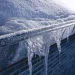
37 Frost protection for gutters and downpipes Melting and refreezing of ice can damage roofs and gutters. Heavy icicles may fall and cause injury. Standing water can leak through interior walls onto furnishings. The Raychem self-regulating snow melting system maintains water flow in gutters and drain pipes and provides a path whereby melting ice and snow can drain safely off the roof, along the gutter and down the drain pipe. Practical to install The self-regulating cable can be closely spaced in gutters without the risk for overheating or burn-outs. There is a cable for each type of roof material. Economical to operate The self-regulating effect saves energy by automatically increasing its heat output in icy water and decreasing its output in dry air. The smart EMDR-10 control unit only switches the heating cable on when necessary: after the detection of both low temperature and moisture. Connection (RayClic-CE-02) Temperature sensor EMDR-10 (Incl.) Moisture sensor EMDR-10 (Incl.) Fixing bracket (GM-RAKE) Frost protection for gutters and downpipes Heating cable (GM-2X) Control unit (EMDR-10) Residual current device (rcd 30 ma) Circuit-breaker (C type) End seal (RayClic-E-02) Do not install RayClic immersed in water. Do not bury RayClic in the ground. CDE-0517 Rev.8 06/10 Technical handbook 37
38 Frost protection for gutters and downpipes Design guide, control units and accessories 1. Heating cable selection GM-2X Self-regulating heating cable for gutters, drain pipes and roof surfaces: 36 W/m in iced water and 18 W/m in air at 0 C 2. Composition of the GM-2X heating cable 1 Copper conductor (1.2 mm 2 ) Self-regulating heating element 3 Insulation made of modified polyolefin 4 Tinned copper braid 5 Protective jacket made of modified polyolefin (UV-resistant) 4 5 Technical data: see page 58 Important note: When laying cables on asphalt, bitumen, roofing felt, etc., a cable with a special fluoropolymer jacket (8BTV- 2-CT) must be used. Frost protection for gutters and downpipes 3. Cable length The heating cable should be installed in a straight line in the gutter The cable lengths should be adjusted according to the geographical situation and the gutters More than one cable should be laid in wide valley, parapet or box gutters Gutter length + drainpipe length + 1 m per connection + 1 m in the soil (frost line) = required heating cable length 4. Electrical protection The length of heating cable determines the number and size of the circuit breakers Residual current device (rcd) : 30 ma required, max. 500 m heating cable per rcd Installation according to local regulations The power connections must be carried out by an approved electrical installer Use C type circuit-breakers Max. length of the heating circuit is based on a minimum switch-on temperature of 10 C, 230 VAC. GM-2X 8BTV-2-CT 6A 25 m 25 m 10 A 40 m 40 m 13 A 50 m 50 m 16 A 60 m 60 m 20 A 80 m 80 m 5. Testing of the installation See page Technical handbook CDE-0517 Rev.8 06/10
39 C C Control units EMDR-10 R EMDR-10 AC 230V 50/60Hz Relais: 10(4)A, AC 230V IP 20 Alarm: 2(1)A, AC 230V TEST 5 25 Do not open while energized Nicht unter Spannung öffnen Ne pas ouvrir sous tension PE PE PE min T2A IEC127 2/V Smart control unit With temperature and moisture sensor User-friendly control Saves up to 80% energy Max. switching capacity 10 A (otherwise switching by contactor) Potential free alarm for sensor break age, sensor short and power loss Technical data: see page 43 HTS-D Standard thermostat 2 independant switching points Max. switching current: 16 A VAC Temperature adjustment range: 20 C to +25 C Outdoor installation Economical for circuit lengths up to 30 m Technical data: see page 45 Frost protection for gutters and downpipes 7. Accessories for GM-2X Avoid installing RayClic in gutters or in places where it may be immersed in water. RayClic-CE-02 Power connection With 1.5 m power cable End seal and support bracket IP 68 External dimension: L = 240 mm W = 64 mm H = 47 mm RayClic-T-02 T-connection Connection for 3 cables 1 end seal and 1 support bracket IP 68 External dimension: L = 270 mm W = 105 mm H = 42 mm RayClic-PT-02 Power T-connection Connection for 3 cables with integral 1.5 m power cable 3 end seals and 1 support bracket IP 68 External dimension: L = 270 mm W = 105 mm H = 42mm CDE-0517 Rev.8 06/10 Technical handbook 39
40 Frost protection for gutters and downpipes RayClic-PS-02 Powered splice Connection for 2 cables with integral 1.5 m power cable 2 end seals and 1 support bracket IP 68 External dimension: L = 270 mm W = 105 mm H = 42 m Frost protection for gutters and downpipes RayClic-E-02 RayClic-LE-02 Gel-filled end seal For system extensions (to be ordered separately) IP 68 RayClic with illuminated end seal For visual representation of voltage (by green lamp) 1 retaining bracket IP 68 External dimension: L = 240 mm W = 64 mm H = 47 mm RayClic-SB-02 Wall-mounted support bracket GM-RAKE Fixing bracket/edge protection for drainpipes Spacer for use in wide channels or gutters where more than one run of cable is required (a spacer is placed every 100 cm) VA steel with UV-resistant cable ties IceStop-GMK-RC Roof clip to secure heating cables to roofs and gutters. Adhesive can be applied on the underside of the roof clip. After curing of the adhesive the heating cable can be clipped between the clamps. GM-Seal Adhesive for sticking and sealing common construction materials with a base of polyurethane 300 ml pack Do not use GM-seal for adhesion on asphalt, bitumen, roofing or similar surfaces Contact your Tyco Thermal Controls representative for more information 40 Technical handbook CDE-0517 Rev.8 06/10
41 CCE-03-CR Cold lead connection and end seal kit Connection of 3 x 1.5 mm 2 or 3 x 2.5 mm 2 cold lead cable to self-regulating heating cable GM-2X 8. Accessories for 8BTV-2-CT heating cable C25-21 Connection kit Heat-schrink technique M25 gland E-06 End Seal kit Frost protection for gutters and downpipes JB Junction box IP 66 6 x 4 mm 2 terminals 4 pg 11/16 and 4 M20/25 knock-out entries JB16-02 AC 660 V IP66 CCE-04-CT Cold lead connection and end seal kit Connection of 3 x 1.5 mm 2 or 3 x 2.5 mm 2 cold lead cable to self-regulating heating cables BTV-2-CT 9. General installation instructions Installation of self-regulating heating cables Store in a dry and clean place. Temperature range: 40 C to +60 C. Protect any cable ends with an end seal. Avoid: sharp edges high tractive force kinking and crushing walking or driving over the cable moisture at cable interfaces CDE-0517 Rev.8 06/10 Technical handbook 41
42 Frost protection for gutters and downpipes 10. Special installation instructions Box gutter < 200 mm One heating cable of GM-2X only Frost protection for gutters and downpipes 200 mm Box gutter > 200 mm Multiple heating cables of GM-2X 2 pc spacer GM-RAKE per meter of gutter edges: GM-RAKE provides mechanical protection against damages In the drainpipe: always install the cable as far as the frost-free area (approx. 1m deep) Fastening of the gutter cables On the roof, eaves bricks, gutter and drainpipe with GM-RAKE edge protection brackets (incl. cable ties). Do not install RayClic immersed in water. Do not bury RayClic in the ground. 42 Technical handbook CDE-0517 Rev.8 06/10
43 Temperature and moisture control unit EMDR-10 Technical data Supply voltage 230 VAC, ±10%, 50Hz Power consumption max. 4 VA AC 230V 50/60Hz Relais: 10(4)A, AC 230V IP 20 Alarm: 2(1)A, AC 230V Max. switching capacity I max 10(4)A / 230 VAC, SPST, potential 230 VAC Do not open while energized Nicht unter Spannung öffnen Ne pas ouvrir sous tension R Temperature adjustment range 3 C to +6 C (factory setting +2 C) EMDR C Lower limit temperature test, 25 C to 5 C (factory setting adjustment range 15 C) T2A IEC127 2/V Operating differential ±0.5 K 5 TEST 0 60 C min PE PE PE Measuring accuracy ±1.5 K Moisture adjustment range 1 (max. sensibility) to 10 (min. sensibility) (factory setting 5) 106 Post heating time adjustment range 0 to 60 minutes (factory setting 60 minutes) Alarm relay I max 2(1)A / 230 VAC, SPDT, potential-free Moisture sensor (output) I max 315mA / 230 VAC, with fuse 5 x 20mm T 315mA according to IEC127-2/V Mounting DIN rail according to DIN EN Low voltage directive EN EMC EN (emission) and EN (immunity) Terminals 2.5 mm 2 (stranded conductors), 4 mm 2 (solid conductors) (Dimensions in mm) Protection class II (panel mounted) Frost protection for gutters and downpipes Housing Ambient temperature range 0 C to +50 C Ingress protection IP20 Housing material Noryl (self-extinguishing according to UL 94 V-0) Weight approx. 350 g Ambient temperature sensor Sensor type PTC (FL 103) (VIA-DU-A10) Ingress protection IP Terminals 2.5 mm 2 Sensor cable 2 x 1.5 mm 2, max. 100 m (not included) Exposure temperature 30 C to +80 C Mounting Wall mounting PG9 (Dimensions in mm) Moisture sensor (HARD-45) Sensor type PTC Power consumption 9 W to 18 W 4m 650 Ambient temperature range 30 C to +65 C continuous active sensor length Supply voltage 230 VAC, ±10%, 50Hz 500 Connection cable 3 x 1.5 mm 2, 4 m, the connection cable can be extended to max. 100 m at 3 x 1.5 mm Ø 9, 5 (Dimensions in mm) 12 x 6 CDE-0517 Rev.8 06/10 Technical handbook 43
44 C C min Frost protection for gutters and downpipes Wiring diagram for EMDR-10 EMDR-10 without contactor L N PE R EMDR-10 AC 230V 50/60Hz Relais: 10(4)A, AC 230V IP 20 Alarm: 2(1)A, AC 230V TEST 5 25 Do not open while energized Nicht unter Spannung öffnen Ne pas ouvrir sous tension PE PE PE mA EMDR-10 DC AC PE PE PE Laod Nedvességé rzékelő Alarm T2A IEC127 2/V Frost protection for gutters and downpipes EMDR-10 with contactor Heating cable Nedvességérz. Hőmérsékletérzékelő L1 L2 L3 N PE PE PE PE N N N L L LS T1 T2 Alarm * Two- or four-pole electrical protection by circuit breaker may be needed for local circumstances, standards and regulations ** Depending on the application, one or three-pole circuit breakers or contactors may be used *** Potential-free alarm contacts for connection to the BMS 44 Technical handbook CDE-0517 Rev.8 06/10
45 Thermostat HTS-D Technical data Temperature range 20 C to +25 C 122 mm Operating voltage AC 230 V, 50 Hz 110 mm 45 mm Max. switch current 16 A / AC 250 V Max. exposure temperature 50 C Switch temperature difference 1 K - 3 K Temperature setting under the housing cover Protective system IP mm 90 mm 29 mm Wiring diagram for HTS-D HTS-D direct Frost protection for gutters and downpipes Self-regulating heating cable * Two- or four-pole electrical protection by circuit-breaker may be needed for local circumstances, standards and regulations CDE-0517 Rev.8 06/10 Technical handbook 45

46 Snow melting for ramps, access ways, and footpaths Ice and snow on paths, loading bays, driveways, ramps, stairs and other access ways, can present a major problem causing accidents and delays. To help prevent this liability, Raychem provides a complete range of ground heating solutions to prevent snow and ice formation. Application in concrete The Raychem range of products has been specifically designed to meet the requirements of commercial, industrial, and residential applications. Whether in concrete, sand, or asphalt, a Raychem system exists to provide a fast, reliable, and easy install solution. Each Raychem heating solution is complete with a Smart control and monitoring unit, providing useful user data and excellent energy efficient performance. The multi-sensor control and monitoring device (VIA-DU-20) is compatible with all ramp snow melting solutions. Ambient temperature sensor* VIA-DU-A10 (incl.) Temperature and moisture sensor VIA-DU-S20 Connection and end seal kit (VIA-CE1) Connection cable (VIA-L1) Snowmelting of ramps, steps and footpaths Control unit (VIA-DU-20) Connection and end seal kit (VIA-CE1) Self-regulating heating cable (EM2-XR) or constant power heating cable (EM4-CW) * Optional, only needed when local detection is selected. Raychem Solutions for concrete Product Description Reinforced concrete surfaces EM2-XR Self-Regulating heating cable for reinforced concrete ramps Domestic and light commercial ground heating applications. Stairs; wheelchair access ramps EM2-CM EM4-CW Pre-terminated constant wattage heating mat for ramp, pavement and track heating 400V Pre-terminated constant wattage heating cable solution for larger concrete areas and stairs 46 Technical handbook CDE-0517 Rev.8 06/10
 Temperature and moisture sensor VIA-DU-S20 Connection between heater cable and cold lead (Pre-engineered) Pre-engineered cold lead Mineral-Insulated heating cable (EM2-MI) Control unit (VIA-DU-20)")
47 Application in asphalt Ambient temperature sensor* VIA-DU-A10 (incl.) Temperature and moisture sensor VIA-DU-S20 Connection between heater cable and cold lead (Pre-engineered) Pre-engineered cold lead Mineral-Insulated heating cable (EM2-MI) Control unit (VIA-DU-20) * Optional, only needed when local detection is selected. Raychem Solutions for installation directly below hot-poured asphalt Snowmelting of ramps, steps and footpaths Product Description Installation in hot asphalt EM2-MI Mineral insulated, high temperature resistant heating cable for asphalt ramps For more information on snow melting products, please refer to document CDE CDE-0517 Rev.8 06/10 Technical handbook 47
48 Snow melting for ramps, access ways, and footpaths System overview Product Features & Selection Guide: Product Features EM2-XR EM2-MI EM2-CM EM4-CW Product Description Self-regulating heating cable Mineral Insulated constant power heating cable Constant power polymeric pre-terminated ramp heating mat system Constant power polymeric pre-terminated heating cable system Features Extremely robust selfregulating heating cable for flexible installation under severe site conditions. Pre-terminated heating cable with exceptional resistance to high temperature asphalt surfaces. Pre-terminated ramp, walkway, and track heating (Roll-out) mat for fast and simple installation. Pre-terminated constant power heating cable for larger areas & 400 V power supplies. Voltage Rating 230 Vac 230 Vac 230 Vac 400 Vac Nominal power output 90 0 C. 50 W/m 300 W/m 2 25 W/m Maximum circuit length 85 m 136 m 12.6 m 2 (Mat size = 21 m x 0,60 m) 250 m Snowmelting of ramps, steps and footpaths Maximum exposure temperature Connections & termination 100 C 250 C 65 C 65 C Cut-to-length system for flexible field termination (using Raychem heatshrink components). Pre-terminated cable lengths (fixed or configured) available. Contact us. Factory pre-terminated Factory pre-terminated Factory pre-terminated Compatible control unit VIA-DU-20 VIA-DU-20 VIA-DU-20 VIA-DU-20 Approvals VDE / CE VDE / CE VDE / CE VDE / CE Suitable for installation on reinforcement bar Highly recommended Recommended Recommended Suitable for installation in direct contact with hot poured asphalt Highly recommended Suitable for embedding in sand sub-level Recommended Recommended Highly recommended Highly recommended Cold lead included Not as standard. Contact Tyco Thermal Controls for information on Configured EM2-XR heating elements. 3 m (at each end of heater cable) 4 m 4 m Dual Wire / Single Wire construction Dual Single Dual Dual 48 Technical handbook CDE-0517 Rev.8 06/10


.")


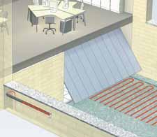
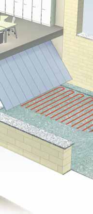
49 Electrical underfloor heating Comfort is everything, especially in the home. With Raychem s smart electrical underfloor heating, you can offer a beautiful warm floor; hassle free to your customers! 5 good reasons to choose Raychem smart underfloor heating 1. Comfortable and safe 2. Hassle free installation and maintenance free 3. Energy-efficient and cost saving 4. Can be installed under all floor coverings 5. Total care warranty The Raychem Underfloor heating range comprises: T2Red: The innovative and unique self- regulating floor heating cable. T2Red with T2Reflecta: The energy-saving underfloor heating system. This system combines the self-regulating heating cable T2Red with T2Reflecta, the grooved, thermally insulated, aluminium-covered plate. T2QuickNet: The ultra thin heating mat (two power options available). T2Blue: The robust, flexible, pre-terminated (dual wire, and screened) cable system. Smart thermostats which offer zoned, programmable heating control, a requirement of Part L of the building regulations. A complete range of installation accessories and components including: Floor primers Adhesives Fixing accessories CeraPro: The ultra thin, robust, under tile heating cable solution with Tape & Mesh fixing accessories included. Electrical underfloor heating CDE-0517 Rev.8 06/10 Technical handbook 49


50 Electrical underfloor heating Smart services for design and specification Raychem offers a comprehensive design and specification service for consultants and architects, free of charge. Using bespoke floor heating design software, we provide: Optimised installation plans for the designer and installer in 2 & 3 dimensional views. Zone by zone product data including heat output per room and per m 2 in the room. Detailed bill of materials, optimised by the software to minimise waste. With a design proposal complete, we provide specification support to ensure quality procurement. Support tools on the web Design and specification tools are available at: Energy consumption calculator Product selection guide A We design it for you e-request service. Building material selection tool Local support from an expert team The Raychem systems and services are supported by a dedicated specifications team. We can provide sound design advice specific to your project needs. Electrical underfloor heating We are also available to: Support consultants and architects at early design/concept stage and provide floor heating options. Visit the project site to survey the requirements and make recommendations for the consultant, client, and contractor. Provide contact details of local suppliers and installers of Raychem floor heating systems. Safety and reliability 12 Total care warranty Quality products - installed and checked by a professional electrician - assure home owners the comfort of a warm floor with Total Care. When installing Raychem floor heating systems, electricians can now offer a 12 Year Total Care Warranty to their customers. Certified Pro* installers can extend the Total Care Warranty up to 20 years. Total Care = doing what it takes to assure a warm floor. In the rare event that our product would fail and we cannot repair it, we will not only provide you with a new product and pay the costs of installing it. We will also take care that the floor covering is repaired or replaced to the equivalent standard. 20 Total care warranty * For more information: ask for the Floorheating handbook or go to 50 Technical handbook CDE-0517 Rev.8 06/10
 - in dry or wet areas. Can be adapted to all room sizes.")

51 T2Red: the intelligent underfloor heating system Senses other sources of heat and adjusts its heat output accordingly. Makes wet floors dry faster. No risk of overheating. Can be installed on all sub floors (plastic, concrete, wood, carpets) - in dry or wet areas. Can be adapted to all room sizes. T2Red cable Subfloor oor or or Subfloor Adhesive Tiles Levelling elling compound o Primer r Water barrier Wood Laminate Adhesive e Wood floor underlay Laminate a Wood Wood floor underlay Screed Adhesive Tiles Adhesive T2Red cable Foil l Metal al mes mesh Insulation Subfloor T2Red with T2Reflecta: the energy-efficient solution The T2Reflecta system combines the self-regulating T2Red heating cable with the pre-grooved T2Reflecta; a thermally insulated, aluminium-covered plate. Provides extra energy savings of 20% or more Can be adapted to all room sizes and be installed on most sub floors. First choice for wooden or laminate floors in dry areas. Automatically adjusts its heat output dependent on ambient floor temperature. Electrical underfloor heating Laminate or wood Wood df floor ru underlay T2Red heating cable T2Reflecta ec ap Plates Levelling compound c Subfloor CDE-0517 Rev.8 06/10 Technical handbook 51
 mat is laid directly in the filler. It can be installed on all sub floors which are sufficiently insulated and conforming to applicable building regulations.")
52 Electrical underfloor heating T2QuickNet: the ideal solution for renovation The thin T2QuickNet mat is the ideal solution for renovation especially for tile floors. The ultra-thin (3 mm) mat is laid directly in the filler. It can be installed on all sub floors which are sufficiently insulated and conforming to applicable building regulations. T2QuickNet exists in two versions: a very popular 90 W/m 2 version and a 160 W/m 2 version when more output is required. Topfloor Tile adhesive T2QuickNet Primer Subfloor Electrical underfloor heating T2QuickNet + Isolecta Insulation board: the insulated, thin heating mat solution for renovation Ideal for renovation projects: Extra insulation layer Fast heat up: Reducing heat up time by additional insulation layer underneath of T2QuickNet Energy savings up to 65% during heat up and 20% in steady state conditions Tiles Tile adhesive T2QuickNet Isolecta 10 mm Subfloor 52 Technical handbook CDE-0517 Rev.8 06/10


 Primer Levelling compound")

53 T2Blue: the flexible underfloor heating cable The flexible underfloor heating cable is suitable for installation directly in a levelling compound, screed, or concrete. Heating cable with pre-fabricated power connection cable Ideal for complex floor layouts. Power output flexibility by varying the distance between heating cables. Suitable for laying in milled grooves in the screed/concrete without increasing the total height of the floor structure Adhesive Tiles Waterproof membrane (optional) Primer Levelling compound T2Blue heating cable Subfloor Electrical underfloor heating Tiles Tile e adhesive Leveling compound compound T2Blue lue ue heating cable ca Foil l Metal mesh Insulation on nt type ype pe Subfloor Subfloor CDE-0517 Rev.8 06/10 Technical handbook 53

54 Electrical underfloor heating CeraPro + Isolecta: the robust, under tile heating cable solution The ultra thin, robust heating cable can be installed directly in the tile adhesive without the need for additional screeding over the heater. The high grade Fluoropolymer material give high resistance to mechanical damage during installation when compared with market alternatives. It can be installed on both wooden and concrete subfloors (maximum installed output of 100 W/m 2 on wooden subfloors.) The heater spacing can be adjusted to allow for typical outputs between 100 and 150 W/m 2. The 6 kit sizes are supplied complete with Tape n Mesh installation products and an easy to use cable spacing guide. Isolecta insulation layer Mesh Tile adhesive Double sided tape Tiles CeraPro heating cable Isolecta 10 mm Subfloor Electrical underfloor heating 54 Technical handbook CDE-0517 Rev.8 06/10
55 General installation instructions Checklist for problem-free installation and safe operation Typical installation schedule for hot water temperature maintenance General order of events The system is designed and the installation planned The pipework is pressure tested or otherwise checked for leaks The HWAT-L/M/R cable is tested and then installed on the designated pipes The components are installed and each circuit is tested The correct thermal insulation is applied, without delay, labelled and the system test repeated The supply voltage cables and circuit breakers are installed to each circuit The system is commissioned (see System start-up below) Circuit protection, testing and operation for all systems Circuit protection Supply voltage 230 VAC, 50 Hz The required protective measures of the relevant regulations must be complied with. C type circuit breaker (anti-surge fuse) Residual current device (rcd 30 ma) required. Maximum approx. 500 m of self-regulating heating cable can be monitored per rcd Measurement A Measurement B Testing Visual inspection for damage and fault-free installation of the accessories Proper installation of the system Heating cable affixed to all necessary pipes No mechanical damage to heating cable (e.g. cuts, cracks, etc.) No thermal damage Proper connection of all components including power supplies Insulation resistance measurement when heating cable is received and before and after installation of the thermal insulation. The test voltage should be 2500 VAC, but it must not be lower than 500 VAC. The insulation resistance, irrespective of the cable length, must not be less than 100 Mohms. If the resistance falls below this value, the source of the fault must be investigated, eliminated, and re-tested. Measurement A: Phase and neutral to the braid Measurement B: Braid to the pipework After switching on, the cable ends must be warm after 5 to 10 minutes Instructions for the placing of the heat insulation For problem-free operation of the self-regulating heating cables, the material quality and thickness of the thermal insulation should be in accordance with the design parameters, and this insulation must be installed correctly All parts of the pipework, including valves, wall transit points, etc. must be fully insulated Operation / System start-up 1) For small installations, turn on the circuit breakers and preferably leave the system overnight for the water to warm up and stabilise 2) For bigger installations or for a faster start-up, first turn on the main water heater and open the outlet/tap at the end of the pipework run until the water feels warm and then turn on the circuit breakers If the piping system is closed, such as by pressure-reducing valves or isolation valves, you must provide some method of pressure relief to allow for thermal expansion of the water during heat-up Under normal operating conditions, the heating cables are maintenance-free. Tyco Thermal Controls recommend that the insulation resistance should be checked periodically and compared with the original values. If the reading falls below the minimum value (100 Mohms) determine the cause and rectify before re-use The specified maximum ambient and operating temperatures should not be exceeded In the event of repair to the pipework, the heating cable must be protected against damage. Correct function of the electrical protection system should be maintained. To prevent shock or personal injury, turn off the power at the circuit breaker before testing or working on the heating cable or piping General installation instructions CDE-0517 Rev.8 06/10 Technical handbook 55
56 General installation instructions Following the completion of the repair work, the circuit should once again be tested (see above) All the important parts of the controls, thermostats, etc. must be checked for correct operation once a year, normally in the autumn Only for hot water temperature maintenance Newly installed heating cables have lower power at start-up of the installation. The nominal power will be reached after approximately 4 weeks of continuous operation The maintenance temperature should be 5 C to 10 C below the hot water temperature in the boiler Standard installation times The actual installation times achieved may deviate according to the conditions on site. Pipework Installation of heating cable on pipes including fastening, standard installation: 25 metres/hour Connection system (electrical connection) RayClic-CE-02 RayClic-S-02/RayClic-PS-02 RayClic-T-02/RayClic-PT-02 RayClic-X-02 RayClic-E-02 2 min/pc. 4 min/pc. 6 min/pc. 8 min/pc. 1 min/pc. Heat-shrink connection system (electrical connection) C min/pc. E-06 5 min/pc. CE min/pc. Other Testing, visual inspection, insulation resistance measurement (2x) Connecting the heating circuit in the switch box 10 min/heating circuit 10 min/heating circuit General installation instructions 56 Technical handbook CDE-0517 Rev.8 06/10
57 Trouble shooting guide Fault Possible causes Measures Circuit-breaker trips: Circuit breaker wrong type: Change to C Type e.g. type B instead of C: Circuit breaker undersized Circuit too long Short-circuit/earth fault Circuit breaker faulty No end seal Conductor (or cable) twisted If the power supply cable permits, install a larger circuit breaker Split the circuit on 2 circuit breakers Eliminate short-circuit/earth fault (cable ends should not be twisted) Replace faulty circuit breaker Install end seal Un-twist and install end seal RCD residual current device trips: More than 500 m of frost protection Install additional rcd residual current heating cable installed per rcd device Earth fault at connection or in end seal Rectify earth fault Cable damaged Repair cable where damaged Moisture in the junction box Eliminate moisture Pipeline does not become warm - Circuit-breaker has tripped See section circuit breaker Heating cable cold: Residual current device has tripped See section residual current device No mains voltage Switch on Cable or cold lead not connected Connect cable or cold lead Cable not inserted correctly in Insert cable according to installation connection system or end seal instructions (fully insert cable) Water temperature is not maintained No insulation Insulation according to tables in but the cable gives high output: Insulation thickness insufficient design guides Insulation wet Dry insulation Cold water is running from the boiler Test boiler temperature Cold water is pumping through mixer Test the mixer tap tap into the hot water pipe. Insulation according to tables in design guides. Note: Installation and operation information is available from Tyco Thermal Controls in document reference: CDE General installation instructions CDE-0517 Rev.8 06/10 Technical handbook 57
58 Technical data Choice of accessories Hot water temperature maintenance Frost protection for pipes Frost protection for gutters and downpipes Snow melting for ramps, access ways, and footpaths Cable type HWAT-L HWAT-M HWAT-R FS-B-2X FS-C-2X GM-2X 8BTV-2-CT EM2-XR EM2-MI EM2-CM EM4-CW Colour Matt Glossy Nominal voltage 230 VAC 230 VAC 230 VAC 230 VAC 230 VAC 230 VAC 230 VAC 230 VAC 230 VAC 230 VAC 230 VAC 230 VAC 400 VAC Nominal power output (*on insulated metal pipes) 7 W/m at 45 C 9 W/m at 55 C 12 W/m at 70 C 10 W/m at 5 C 26 W/m at 5 C 31 W/m at 5 C 22 W/m at 40 C 10 W/m at 5 C 36 W/m in ice and 18 W/m in air at 0 C 18 W/m in air at 0 C 36 W/m in ice at 0 C 90 W/m at 0 C 50 W/m 300 W/m 2 25 W/m C-type circuitbreaker according to selected kit max. 20 A max. 20 A max. 20 A max. 16 A max. 16 A max. 16 A max. 20 A max. 20 A max. 20 A max. 50 A max. 20 A max. 20 A max. 20 A Max. circuit length 180 m 20 A 100 m 20 A 100 m 20 A 150 m 16 A 105 m 16 A 90 m 16 A 180 m 20 A 80 m 20 A 80 m 20 A 85 m 50 A 136 m 21 m (12.6 m 2 ) 250 m Min. bending radius 10 mm 10 mm 10 mm 10 mm 10 mm 10 mm 10 mm 10 mm 12,7 mm (at 20 C) 50 mm 50 mm 30 mm Max. continous exposure temperature 65 C 65 C 80 C 65 C 65 C 95 C 90 C 65 C 65 C 100 C 250 C 65 C 65 C Max. exposure temperature (power-on condition 800 h. cumulative) 85 C 85 C 90 C 85 C 85 C 95 C 90 C 85 C 85 C 110 C 250 C 65 C 65 C Max. dimensions in mm (W x H) 13.8 x x x x x x x x x x 9.5 min 4,8; max. 6,3 5,0 x 7,0 5,0 x 7,0 Weight 0.12 kg/m 0.12 kg/m 0.14 kg/m 0.13 kg/m 0.13 kg/m 0.13 kg/m 0.14 kg/m 0.13 kg/m 0.13 kg/m 0.27 kg/m Approvals BS / ÖVE / VDE / SEV / CSTB / SVGW / DVGW / CE / VDE CE / VDE Control units QWT-05 HWAT-ECO** HWAT-ECO** HWAT-ECO** AT-TS-13 AT-TS-14 RAYSTAT-CONTROL-10 RAYSTAT-ECO-10** RAYSTAT-CONTROL-11-DIN AT-TS-13 AT-TS-14 RAYSTAT-CONTROL-10 RAYSTAT-ECO-10** RAYSTAT-CONTROL-11-DIN AT-TS-13 AT-TS-14 RAYSTAT-CONTROL-10 RAYSTAT-CONTROL-11-DIN AT-TS-13 AT-TS-14 RAYSTAT-CONTROL-10* RAYSTAT-ECO-10** RAYSTAT-CONTROL-11-DIN EMDR-10** HTS-D VIA-DU-20** VIA-DU-20** VIA-DU-20** VIA-DU-20** Connection system Junction box JB16-02 JB16-02 JB16-02 VIA-JB2 VIA-JB-2 VIA-JB-2 VIA-JB-2 Connection kit RayClic RayClic RayClic RayClic RayClic CE20-01 CE20-01 RayClic CE25-21 E-06 VIA-CE1 Pre-installed Support bracket included in the kit included in the kit included in the kit included in the kit included in the kit JB-SB-08 JB-SB-08 included in the kit JB-SB-08 Approvals: BS/VDE/ÖVE/ERFA/CE * For max circuit, Raystat controller will be required. ** 58 Technical handbook CDE-0517 Rev.8 06/10
59 CDE-0517 Rev.8 06/10 Technical handbook 59

60 Raychem offers a set of tools and services that aim to simplify the professional s life. Not only do we offer the best quality products, we also support them with unrivalled services. Member of the European Radiant Floor Heat ing Association e.v. Our products satisfy the requirements of the relevant European Directives. An efficient customer service centre: Multi-lingual customer service representatives to answer all your questions Fast order handling & shipment Europe-wide Free documentation service Chartered institute of Building Services Engineers Tyco Thermal Controls is also a proud industry supporter offering approved CPD courses via the Chartered Institute of Building Services Engineers. Courses include technical and application information for electrical underfloor heating and hot water temperature maintenance systems. For further information, please consult the CIBSE Course Directory 2010 or contact Tyco Thermal Controls. Large technical support team: On demand technical advice and product selection Design support and cost estimates Specification support Training support Installation, test and commissioning support Complete after-sales service Online design design wizard TraceCalc Net Online technical Support SalesUK@tycothermal.com CALL FAX T2, Pyrotenax, DigiTrace, Isopad, TraceTek and Tracer are registered trademarks of Tyco Thermal Controls, LLC or it s affiliates. All of the above information, including illustrations, is believed to be reliable. Users however, should independently evaluate the suitability of each product for their application. Tyco Thermal Controls makes no warranties as to the accuracy or completeness of the information and disclaims any liability regarding its use. Tyco Thermal Controls only obligations are those in the Standard Terms and Conditions of Sale for this product and in no case will Tyco Thermal Controls be liable for any incidental, indirect or consequential damages arising from the sale, resale, use or misuse of the product. Tyco Thermal Controls Specifications are subject to change without notice. In addition Tyco Thermal Controls reserves the right to make changes in materials or processing, without notification to the Buyer, which do not affect compliance with any applicable specification Tyco Thermal Controls CDE-0517 PCN Rev.8 06/10 Printed on chlorine-free bleached paper. United Kingdom Tyco Thermal Controls (UK) Ltd 3 Rutherford Road, Stephenson Industrial Estate Washington, Tyne & Wear NE37 3HX Free phone Free fax salesuk@tycothermal.com Ireland Free phone Free fax salesie@tycothermal.com European Headquarters Tyco Thermal Controls Romeinse Straat Leuven Belgium
Hot water temperature maintenance. Less water volume and less heat loss in the pipe work help prevent bacteriological
 Providing the comfort of instant hot water is the key requirement of any modern hot water system. The Raychem single-pipe system keeps water at the right temperature in a building s water distribution
DESIGN GUIDELINES. THERMAL building SOLUTIONS
 DESIGN GUIDELINES XL-Trace LSZH Self-Regulating Heating Cables for Pipe Freeze Protection Systems THERMAL building SOLUTIONS WWW.PENTAIRTHERMAL.COM Pipe Freeze protection system overview SBS Control Panel
Technical handbook. Temperature maintenance and frost protection systems
 R Technical handbook Temperature maintenance and frost protection systems Useful instructions for the use of this technical handbook For your customers... For the worksite... COPY FAX COPY COPY The as
Snow melting for ramps, access ways, and footpaths
 Snow melting for ramps, access ways, and footpaths Ice and snow on paths, loading bays, driveways, ramps, stairs and other access ways, can present a major problem causing accidents and delays. To help
Hot Water Temperature Maintenance. HWAT System. Product Selection and Design Guide
 Hot Water Temperature Maintenance HWAT System Product Selection and Design Guide A Solutions Company Tyco Thermal Controls provides complete heat tracing and specialty wiring solutions for the industrial,
Polymer solutions Heating mat EM2-CM
 1.5 Polymer solutions 1. Application EM2-CM is a constant wattage heating mat for simple, fast, and effective ramp and accessway heating to prevent snow and ice formation. The EM2-CM mat is particularly
SPECIFICATION GUIDELINE FROST PROTECTION FOR PIPES. Tender Specification. Engineering Specification for Pipe Frost Protection. Contents.
 Tender Specification Package #: Trace Heating Engineering Specification for Pipe Frost Protection Contents Y24 Trace heating 2 Appendix A Schematics & Drawings 8 Prepared by: Authorised by: Issued
HOT WATER TEMPERATURE MAINTENANCE HWAT SYSTEM
 HOT WATER TEMPERATURE MAINTENANCE HWAT SYSTEM This step-by-step design guide provides the tools necessary to design a Raychem HWAT Hot Water Temperature Maintenance System. For additional information,
XL-Trace System Application and Design Guide
 R XL-Trace System Application and Design Guide Pipe Freeze Protection and Flow Maintenance for Commercial Construction Applications Pipe Freeze Protection and Flow Maintenance 1. Pipe Freeze Protection
Design Guide Design Notes Design Examples Technical Data Sheets Expanded Capabilities Specifications Warranty
 Introduction HWAT Design Guide This step-by-step design guide provides the tools necessary to design a Raychem HWAT Hot Water Temperature Maintenance System. For additional information, contact your Pentair
HWAT -ECO. Installation and Operation Manual. Electronic controller for hot water temperature maintenance systems
 HWAT -ECO Installation and Operation Manual Electronic controller for hot water temperature maintenance systems B A C F HWAT -ECO Installation and Operation Manual D Electronic controller for hot water
Pipe Freeze Protection. Flow Maintenance. Introduction. XL-Trace System
 Pipe Freeze Protection and Flow Maintenance 1. Pipe Freeze Protection and Flow Maintenance Introduction XL-Trace System This step-by-step design guide provides the tools necessary to design a Raychem XL-Trace
CSI Master Format 2012 Guide Specification for: Hot Water Temperature Maintenance (HWAT) Systems
 Systems") CSI Master Format 2012 Guide Specification for: Hot Water Temperature Maintenance (HWAT) Systems System for temperature maintenance of domestic hot water supply systems with energy efficient time based
CSI Master Format 2012 Guide Specification for: Hot Water Temperature Maintenance (HWAT) Systems System for temperature maintenance of domestic hot water supply systems with energy efficient time based
Roof and Gutter De-Icing
 Roof and Gutter 1. Pipe Freeze Protection and Flow Maintenance Introduction IceStop System This step-by-step design guide provides the tools necessary to design a Raychem IceStop roof and gutter de-icing
FIRE SPRINKLER SYSTEM FREEZE PROTECTION XL-TRACE SYSTEM
 FIRE SPRINKLER SYSTEM FREEZE PROTECTION XL-TRACE SYSTEM This step-by-step design guide provides the tools necessary to design a Raychem XL-Trace fire sprinkler freeze protection system. For other applications
ACS-30-EU-EMDR- 10-MOD
 ACS-30-EU-EMDR- 10-MOD MULTI-APPLICATION HEAT TRACING CONTROL AND MONITORING IN COMMERCIAL AND RESIDENTIAL BUILDINGS ROOF & GUTTER DE-ICING SENSOR MODULE TECHNICAL INFORMATION DESCRIPTION The nvent RAYCHEM
CSI Master Format 2004 Guide Specification for: Flow Maintenance of Above Ground Greasy Waste Disposal Lines
 CSI Master Format 2004 Guide Specification for: Flow Maintenance of Above Ground Greasy Waste Disposal Lines System for flow maintenance of above ground greasy waste disposal lines with line sensing control,
Selection guide for self-regulating heat-tracing systems
 R Selection guide for self-regulating heat-tracing systems R TraceCalc Net, software design in three easy steps: 1. Select your heat-tracing design 2. Enter the design data >> 3. Get a bill of materials
F1202 TRACE HEATING. Road & Ramp
 Trace Heating Specialists Road & Ramp ROAD & RAMP HEATING ESH Trace Heating Ltd provide a comprehensive range of products to prevent the settlement of snow and formation of ice on roads, ramps and stairs.
CSI Master Format 2004 Guide Specification for: Flow Maintenance of Aboveground Fuel Oil Lines
 CSI Master Format 2004 Guide Specification for: Flow Maintenance of Aboveground Fuel Oil Lines System for flow maintenance of aboveground fuel oil lines with Proportional Ambient Sensing Control (PASC),
Hot Water Temperature Maintenance Product Selection and Design Guide
 Hot Water Temperature Maintenance Product Selection and Design Guide A Solutions Company Tyco Thermal Controls provides complete heat tracing and specialty wiring solutions for the industrial, commercial,
Data Sheet. Self regulating process heating tapes RS stock numbers ,
 Data Pack K Issued March 1997 232-3333 Data Sheet Self regulating process heating tapes RS stock numbers 379-889, 379-974 The information contained within this sheet regarding applications and installation
Freezer Frost Heave Prevention
 Freezer Frost Heave Prevention 1. Pipe Freeze Protection and Flow Maintenance RaySol System Mineral Insulated Heating Cable System This step-by-step design guide provides the tools necessary to design
RayClic Connection System
 RayClic Connection System RayClic-S Splice Kit RayClic-T Tee and End Seal Kit RayClic-X Cross and End Seal Kit Installation Instructions Description These kits are for use with Raychem IceStop, XL-Trace
Data Sheet. Self regulating heating tapes. RS stock numbers
 Data Pack K Issued September 2001 232-3125 Data Sheet Self regulating heating tapes RS stock numbers 379-312 The information contained within this sheet regarding applications and installation of RS WinterGard
ROOF AND GUTTER DE-ICING ICESTOP SYSTEM
 ROOF AND GUTTER DE-ICING ICESTOP SYSTEM This step-by-step design guide provides the tools necessary to design a Raychem IceStop roof and gutter de-icing system. For other applications or for design assistance,
Danfoss Self-limiting Heating Cables SLPG-10/26/33, SLPG-18, SLHW-55/70, SLPH-10
 MAKING MODERN LIVING POSSIBLE Installation Guide SLPG-10/26/33, SLPG-18, SLHW-55/70, SLPH-10 www.eh.danfoss.com Table of Contents 1 Introduction............................................. 3 1.1 Self-limiting
Union County Vocational - Technical Schools Scotch Plains, New Jersey
 SECTION 220533 - HEAT TRACING FOR PLUMBING PIPING PART 1 - GENERAL 1.1 SUMMARY A. This Section includes plumbing piping heat tracing for freeze prevention, domestic hot-water-temperature maintenance, and
Documentation. Parallel Heating Cable. Type: ELP
 Documentation Parallel Heating Cable Type: ELP 05.01.2018 K. Folkerts Content 1. Data sheet 2. Installation instructions 3. Declarations of conformity 05.01.2018 K. Folkerts 1 05.01.2018 K. Folkerts Constant
Domestic Hot Water Application manual
 Document Electrical Heating category Product name Domestic Hot Water Application manual 90% of the Legionella bacteria dies within the first 2 min at 60 C Let Danfoss do the work Index Danfoss Group is
THERMAL MANAGEMENT SOLUTIONS
 Pipe Freeze Protection and Flow Maintenance ECW-GF, ECW-GF-DP Digital electronic controllers and remote display panel Fire Sprinkler System Freeze Protection ECW-GF with FTC-PSK pipe stand and power connection
IceStop System Installation and Operation Manual
 IceStop System Installation and Operation Manual For Roof and Gutter De-Icing WARNING: Fire and Shock Hazard. The IceStop roof and gutter de-icing system must be installed correctly to ensure proper operation
ACS-30-EU-VIA-DU-20-MOD
 Multi-application heat tracing Control & Monitoring in commercial and residential buildings Surface Snow melting sensor Module Description The Raychem ACS-30-EU-VIA-DU-20-MOD Module for the ACS-30 system
ACS-30 MULTIPOINT COMMERCIAL HEAT-TRACING SYSTEM PRODUCT OVERVIEW. ACS-30 System
 SHIFT TEST BACK ENTER C910 SERIES STATUS OUTPUT ACS-30 MULTIPOINT COMMERCIAL HEAT-TRACING SYSTEM ACS-30 System MONITOR CONFIG POWER CONTROL MODULE ACCS-PCM-5 PROGRAMMABLE SINGLE POINT HEAT-TRACING CONTROLLER
Technical Databook for Industrial Heat-Tracing Systems 2006/2007
 R Technical Databook for Industrial Heat-Tracing Systems 2006/2007 www.tycothermal.com Tyco Thermal Controls brings together the knowledge, expertise, products and services of the leading brands in industrial
Ready-to-Use Heat Tracing Solutions for Laboratory Applications. innovations in heat tracing
 Ready-to-Use Heat Tracing Solutions for Laboratory Applications innovations in heat tracing eltherm GmbH Solutions with Electric Heat Tracing Systems eltherm GmbH is an internationally operating engineering
THERMAL MANAGEMENT SOLUTIONS
 DIGITAL ELECTRONIC CONTROLLERS AND REMOTE DISPLAY PANEL ECW-GF with FTC-PSK pipe stand and power connection kit ECW-GF using RayClic power connection kit ECW-GF-DP remote display panel available only with
CSI Master Format 2004 Guide Specification for: Freezer Frost Heave Prevention (Mineral Insulated)
") CSI Master Format 2004 Guide Specification for: Freezer Frost Heave Prevention (Mineral Insulated) System for preventing frost heave in freezers, cold rooms and ice arenas with temperature control, monitoring,
CSI Master Format 2004 Guide Specification for: Freezer Frost Heave Prevention (Mineral Insulated) System for preventing frost heave in freezers, cold rooms and ice arenas with temperature control, monitoring,
QAF64.2-J QAF64.6-J. Frost detector. for use on the air side
 s Frost detector for use on the air side QAF64.2-J QAF64.6-J With active capillary tube sensing element for acquiring the lowest temperature within a range of 0 15 C With startup function Operating voltage
HTC-915-CONT. Heat-Trace Control system
 Heat-Trace Control system Product overview The Raychem HTC-915 system is a compact, full-featured microprocessor-based single-point heat-trace controller. The HTC-915-CONT provides control and monitoring
ECW-GF, ECW-GF-DP DIGITAL ELECTRONIC CONTROLLERS AND REMOTE DISPLAY PANEL PRODUCT OVERVIEW
 DIGITAL ELECTRONIC CONTROLLERS AND REMOTE DISPLAY PANEL ECW-GF with FTC-PSK pipe stand and power connection kit ECW-GF using RayClic power connection kit ECW-GF-DP remote display panel available only with
COMMERCIAL HEAT TRACING PRODUCTS AND SERVICES
 COMMERCIAL HEAT TRACING PRODUCTS AND SERVICES THERMAL MANAGEMENT SOLUTIONS WWW.THERMAL.PENTAIR.COM BUILDING & INFRASTRUCTURE SOLUTIONS We provide quality solutions for winter safety, comfort and performance
RAYCHEM NGC-30 COMPONENTS
 PANEL MOUNTED ELECTRONIC MULTI-CIRCUIT HEAT-TRACING CONTROL, MONITORING AND POWER DISTRIBUTION SYSTEM PRODUCT OVERVIEW CABLE DUCT Card Rack Modules TERMINAL STRIP PLINTH MAIN SWITCH 800 mm USER INTERFACE
CABLE SERVICES. Data Input Sheet - Fax Back
 Trace Heating Guide Data Input Sheet - Fax Back 3 TRACE HEATING GUIDE Distributor of Trace Heating Products for 25 Years (Northwest) Ltd Tel 01978 356948 (UK) Ltd Tel 01978 3450 (Central) Ltd Tel 01782
IceStop System INSTALLATION AND OPERATION MANUAL FOR ROOF AND GUTTER DE-ICING SYSTEMS
 IceStop System INSTALLATION AND OPERATION MANUAL FOR ROOF AND GUTTER DE-ICING SYSTEMS THERMAL MANAGEMENT SOLUTIONS WWW.THERMAL.PENTAIR.COM Important Safeguards and Warnings WARNING: FIRE AND SHOCK HAZARD.
Gardian W51. Approvals
 Gardian W51 120 V pre-assembled electric heating cables for pipe freeze protection and roof & gutter de-icing Installation Instructions Description Gardian W51 120 V pre-assembled self-regulating heating
Principle of Operation:
 SELF-REGULATING HEATERS Standard Overjacket Standard Metal Braid Stranded Copper Conductors Self Regulating Conductive Core Thermoplastic Elastomer Jacket Description: Nelson Type CLT selfregulating heater
PANEL MOUNTED ELECTRONIC MULTI-CIRCUIT HEAT-TRACING CONTROL, MONITORING AND POWER DISTRIBUTION SYSTEM mm. 100 mm
 PANEL MOUNTED ELECTRONIC MULTI-CIRCUIT HEAT-TRACING CONTROL, MONITORING AND POWER DISTRIBUTION SYSTEM Card Rack Modules CABLE DUCT MAIN SWITCH 800 mm USER INTERFACE TERMINAL PRODUCT OVERVIEW The nvent
XL-Trace System. Installation and Operation manual for pipe freeze protection and flow maintenance
 XL-Trace System Installation and Operation manual for pipe freeze protection and flow maintenance Thermal management WWW.PENTAIRTHERMAL.COM Important Safeguards and Warnings WARNING: FIRE AND SHOCK HAZARD.
Refrigeration and Air Conditioning Technical leaflet. Electronic controller EKC 201 and EKC 301
 Refrigeration and Air Conditioning Technical leaflet Electronic controller EKC 201 and EKC 301 RC.5L.A1.02 RC.5L.A2.02 09-1998 Introduction EKC 201 and 301 are used for temperature control compressor control
Leakage Detection. WaterAlarmSystems Fuel-oil/WaterAlarms. Safe protection for plants and buildings...leakage Detection Systems provided by BARTEC
 Leakage Detection WaterAlarmSystems Fuel-oil/WaterAlarms Safe protection for plants and buildings...leakage Detection Systems provided by BARTEC Reservation Technical data is subject to change without
Single Point Freeze Protection Heat Trace Control TRACON MODEL FPT 130 Installation and Operation Manual
 We manage heat MANUAL Single Point Freeze Protection Heat Trace Control TRACON MODEL FPT 130 Installation and Operation Manual 1850 N Sheridan Street South Bend, Indiana 46628 (574) 233-1202 or (800) 234-4239
Documentation. Glass -/quartz insulated Heating Cable. Factory terminated. Type: ELK-H, -HS, -Q ELW-H, -HS, -Q
 Documentation Glass -/quartz insulated Heating Cable Factory terminated Type: ELK-H, -HS, -Q ELW-H, -HS, -Q 05.01.2018 K. Folkerts Content 1. Data sheet 2. Installation instructions 3. Declarations of
COMMERCIAL & RESIDENTIAL MARKETS U.S. ELECTRICAL
 COMMERCIAL & RESIDENTIAL MARKETS U.S. ELECTRICAL THERMAL BUILDING SOLUTIONS WWW.PENTAIRTHERMAL.COM Because winters can be harsh In winter, freezing temperatures can be a latent danger for buildings and
XL-Trace System Installation and Operation Manual
 XL-Trace System Installation and Operation Manual Pipe freeze protection and flow maintenance WARNING: Fire and shock hazard. This heat-tracing system must be installed correctly to ensure proper operation
C910 Series. Single-point heat-tracing control system
 1. Pipe Freeze Protection and Flow Maintenance Single-point heat-tracing control system 2. Roof and Gutter De-Icing Product overview The DigiTrace C910 is a compact, fullfeatured, microprocessor-based,
Corporate Profile. needs and product demands. CON 08X /03 Rev 0
 Corporate Profile A leader in the field of electrochemical instrumentation, Eutech Instruments is a dynamic company rapidly positioning itself globally as a leading manufacturer of electrochemical instrumentation
Carbon Film Installation Instructions
 Contents Page 2 Page 3 Page 4 Page 5 Page 8 Product Overview Pre-Installation & Electrical Provision Depron Underlay Installation Carbon Film Installation - Under Wood/Laminate Flooring Notes & Trouble
PLSRR Heat Trace Cable Data Sheet
 PLSRR Heat Trace Cable Data Sheet PLSRR is self-regulating heat cable that can be used for roof / gutter heating pipe tracing. The cable features a flexible, UV-stabilized thermoplastic elastomer overjacket
Pipe Freeze Protection Control SCFP-CO-F130 Installation and Operation Manual
 MANUAL Pipe Freeze Protection Control SCFP-CO-F130 Installation and Operation Manual Model FPT 130 Single Point Freeze Protection Heat Trace Control Table of Contents SCFP-CO-F130 Overview... 3 Installation...
Installation Guide. Heating cables. Pipe tracing. Intelligent solutions with lasting effect. Visit DEVI.com
 Installation Guide Heating cables Pipe tracing Intelligent solutions with lasting effect Visit DEVI.com Table of Contents 1 Introduction.................... 3 1.1 Safety Instructions...............3 1.2
FTC-HST WARNING: CAUTION:
 FTC-HST XL-Trace, RaySol, and IceStop Splice/Tee Connection Kit Installation Instructions Description The Raychem FTC-HST is used with RaySol system heating cables to make splice connections (on slab bottoms
1.7. Insulation fault evaluators EDS460/490 EDS461/491
 Bender Incorporated 700 Fox Chase, Coatesville PA 1930 Tel.: (800) 356-466 Fax: (610) 383-7100 Insulation fault evaluators EDS460/490 EDS461/491 Insulation fault evaluators with display and control function
HEAT MONITORING AND CONTROL INSTRUMENTS FOR TRANSFORMERS MB 103 TEMPERATURE CONTROL UNIT PT 100 TEMPERATURE SENSOR
 HEAT MONITORING AND CONTROL INSTRUMENTS FOR TRANSFORMERS MB 103 TEMPERATURE CONTROL UNIT PT 100 TEMPERATURE SENSOR 2 MB 103 TRANSFORMER TEMPERATURE CONTROL UNIT WITH CONTROL SIGNAL Recent approval of new
GM420. Digital Ground Continuity Relay For AC Systems. Technical Bulletin NAE /
 3 GM20 Digital Ground Continuity Relay For AC Systems Technical Bulletin NAE03230 / 0.20 GM20 Ground continuity monitor For AC systems Description The GM20 monitors the loop resistance of ground conductors
Temperature Control and Monitoring. innovations in heat tracing
 Temperature Control and Monitoring innovations in heat tracing Table of Contents Overview 4-5 Type Ex-Box REG/DIS Type Ex-Box REG/LED Temperature Controller for Hazardous Areas Temperature Controller for
MODEL FPT-130 SINGLE POINT FREEZE PROTECTION HEAT TRACE CONTROL
 TRACON MODEL FPT-130 SINGLE POINT FREEZE PROTECTION HEAT TRACE CONTROL TABLE OF CONTENTS FPT 130 Overview... 2 Installation... 3 Power Source and Load Connections... 4 Temperature Sensor... 5 External
Duct Temperature Sensors
 1 762 1761P03 1762P01 Mounting flange AQM630 QAM21 Symaro Duct Temperature Sensors QAM2161040 QAM2171040 Active sensors for acquiring the air temperature in air ducts AC 24 V or DC 13535 V Signal output
INSTALLATIONGUIDE. HotSeam TM Overview ICE ROOF
 INSTALLATION GUIDE forfor HotSeam HotSeam Overview Exposed heat cables with glued down retention clips on metal roofs have been the conventional way to drain ice dams for many years. HotEdge s patented
C SINGLE-POINT HEAT-TRACING CONTROL SYSTEM PRODUCT OVERVIEW
 SINGLE-POINT HEAT-TRACING CONTROL SYSTEM PRODUCT OVERVIEW SHIFT TEST SHIFT C910 SERIES ALARM MONITOR CONFIG BACK ENTER PROGRAMMABLE SINGLE POINT HEAT-TRACING CONTROLLER HEAT-TRACING CONTROLLER STATUS ALARM
DEB71. Earth Leakage Monitoring Relay. Benefits. Description
 Earth Leakage Monitoring Relay Benefits Adjustable trip level. Adjustable leakage threshold from 30mA to 5A or from 300mA to 30A. 2 outputs. Two relay outputs provide, besides the alarm signal an additional
METAL SHARK COMBI Flat metal detector for textile and non-woven products. Metal sensitivity from Fe 0,3 mm
 METAL SHARK COMBI Flat metal detector for textile and non-woven products Metal sensitivity from Fe 0,3 mm METAL SHARK - The new generation in metal detecting technology Introducing the METAL SHARK presenting
Toll Free:
 1 ProLine s electric radiant floor heating system is one of the most popular and durable floor heating solutions on the market. Available pre-spaced in mats with an adhesive backing or on the spool, the
CSI Master Format 2004 Guide Specification for: Snow Melting (Mineral Insulated)
") CSI Master Format 2004 Guide Specification for: Snow Melting (Mineral Insulated) Typical system for snow melting of pavers, concrete and asphalt surfaces with temperature and moisture sensing control,
CSI Master Format 2004 Guide Specification for: Snow Melting (Mineral Insulated) Typical system for snow melting of pavers, concrete and asphalt surfaces with temperature and moisture sensing control,
UPONOR Ltd. Specification for UPONOR Q&E PEX Shrinkfit Plumbing Systems
 UPONOR Ltd Specification for UPONOR Q&E PEX Shrinkfit Plumbing Systems Reference Page(s) UPONOR Q&E PEX 2 Operating Conditions 2 Pipe Properties 2 Fittings Range 3 Radiator Heating Systems 3 H&C Water
protection Constant wattage heating cables Self-regulating heating cables Temperature controllers
 snow & ice protection Constant wattage heating cables Self-regulating heating cables Temperature controllers Protection of roofs, gutters and downpipes Snow and ice protection systems protect against:
OPTISENS TUR 2000 Technical Datasheet
 OPTISENS TUR 2000 Technical Datasheet Sensor for turbidity measurement in water and wastewater Rugged design for harsh applications Integrated transmitter with direct 4...20 ma output Near infrared light
VERTEX VT10 SERIES PID OPERATION MANUAL MICROPROCESSOR BASED PID CONTROLLER
 1 VERTEX VT10 SERIES PID OPERATION MANUAL MICROPROCESSOR BASED PID CONTROLLER 1. INTRODUCTION This manual contains information for the installation and operation and tuning of our Vertex VT10 series self-tuning
Installation Manual. Electric Underfloor Heating. heatingthroughinnovation.
 Installation Manual Electric Underfloor Heating heatingthroughinnovation. 02 Electric Underfloor Heating Contents 1.0 General Information 03 2.0 Preparation 04 3.0 Installation 05 4.0 Measuring Values
PRELIMINARY EDITION
 3 131 PRELIMINARY EDITION 14.01.2003 Synco 700 Heating Controllers Heating controller for medium-size and large buildings. The is used as a heating circuit or primary controller. The controller is supplied
Installation Manual. Frost Protection Cable. Warmup Ireland Web: Telephone:
 Installation Manual Frost Protection Cable Warmup Ireland Web: www.warmup.ie Email: ie@warmup.com Telephone: 1 800 937 429 TECHNICAL HELPLINE 0845 345 2288 IMPORTANT Read this manual before attempting
Installation, operating and servicing instructions
 English 57-115 - 144-1 - 259 Installation, operating and servicing instructions ITALIA EN 1 ITALIA English INDEX WARnINGS 3 Who should read these instructions 3 Symbols 3 Recommendations 3 Importants notes
Frost Protection Thermostat
 1 203 Frost Protection Thermostat Electromechanical thermal reset limit thermostat RAK-TW.5..H RAK-TW.5..H.. Use Monitoring of frost protection temperature, with single-pole changeover microswitch Switching
COLD WEATHER SOLUTIONS: ELECTRIC HEAT AND CONTROL PRODUCTS
 COLD WEATHER SOLUTIONS: ELECTRIC HEAT AND CONTROL PRODUCTS INDUSTRIAL AIR AND INFRARED RADIANT HEATERS Portable Unit Heaters Portable electric heaters are available in radiant-heat or fan-forcedair designs.
Consignes d installation
 PBS-200-A Single entry power junction box Installation Instructions PBS-200-A Single entry power junction box with cold applied connection technology for use with BARTEC PSB / HSB trace heaters Consignes
Serie Rugghölzli 2 CH Busslingen. Tel. +41 (0) Fax +41 (0)
 Fax +41 (0)") Serie 5000 Tel. +1 (0)5 222 Fax +1 (0)5 222 12 PRODUCT INTRODUCTI PRODUCT INTRODUCTI 5 Series programmable temperature controller is FineTek's mid-range series of controllers. It uses a 12bit analog /
Serie 5000 Tel. +1 (0)5 222 Fax +1 (0)5 222 12 PRODUCT INTRODUCTI PRODUCT INTRODUCTI 5 Series programmable temperature controller is FineTek's mid-range series of controllers. It uses a 12bit analog /
DT92 WIRELESS DIGITAL ROOM THERMOSTAT FEATURES PRODUCT SPECIFICATION SHEET
 DT92 WIRELESS DIGITAL ROOM THERMOSTAT PRODUCT SPECIFICATION SHEET The new DT92 family of wireless digital room thermostats is a range of market leading products designed to provide comfort with economy
Technical Data Manual
 VITOTRONIC 300 Weather-responsive indoor/outdoor, digital boiler control for heating systems with one or more heating circuits Technical Data Manual Vitotronic 300 Model KW3, Part No. Z001 231 For operation
ACCS-30. Multipoint commercial heat-tracing control system
 Multipoint commercial heat-tracing control system Product Overview The DigiTrace ACCS-30 is a multipoint electronic control and monitoring system for heat-tracing used in commercial freeze protection and
C A Heating Cable Gland Kit
 C75-100-A Heating Cable Gland Kit Installation Instructions Description The C75-100-A is a NEMA 4X rated gland kit used to transition heating cables into a junction box when making connections off of a
Snifter ATEX22 VERSION. User Manual. Distributor
 Snifter ATEX22 VERSION User Manual Distributor Version 1.4 09/09/2009 Table of Contents 1. INTRODUCTION... 3 1.1. Safety... 3 1.2. Product overview... 4 1.3. How does it work?... 4 2. INSTALLATION... 5
Miniature Infrared Temperature Sensors with Optional Touch Screen Display. PSC-SSS-PM with touch screen display (-CRT version)
") PSC-SSS-PM Series Miniature Infrared Temperature Sensors with Optional Touch Screen Display PSC-SSS-PM with touch screen display (- version) FEATURES Miniature sensing head and configurable electronics
PSC-SSS-PM Series Miniature Infrared Temperature Sensors with Optional Touch Screen Display PSC-SSS-PM with touch screen display (- version) FEATURES Miniature sensing head and configurable electronics
Remote alarm indicator and test combination MK2430
 Dipl.-Ing. W. Bender GmbH & Co. KG Londorfer Str. 5 35305 Grünberg Tel.: 040 807-0 Fax: 040 807-259 Remote alarm indicator and test combination MK2430 Remote alarm indicator and test combination with LC
CM901 PROGRAMMABLE THERMOSTAT FEATURES PRODUCT SPECIFICATION SHEET
 CM90 PROGRAMMABLE THERMOSTAT PRODUCT SPECIFICATION SHEET FEATURES Attractive, slim, ultra-modern styling makes it ideal for location in any type of home. 24 hour heating program. A dynamic text display
Process Alarm Module RTA 421
 Technical Information TI 074R/24/ae Process Alarm Module RTA 421 Alarm module and power supply for monitoring current or voltage signals Application Areas Plant and machine construction Panel builders
RE-PR3-E-27 3-Phase Panel Mount 27kW
 Page 1 of 6 RE-PR3-E-27 3-Phase Panel Mount 27kW Features: Benefits: 0-10Vdc, 0-5Vdc, 4-20mA or manual via potentiometer control input Over temperature protection with auto reset Enclosed panel mounting
Technical Databook for Industrial Heating Systems
 Technical Databook for Industrial Heating Systems R 2003 / 2004 Edition www.tycothermal.com Tyco Thermal Controls brings together the knowledge, expertise, products and services of the five leading brands
Safety Temperature Limiter STL 50 Certified to DIN EN (replaces DIN 3440)
") Safety Temperature Limiter STL 50 Certified to DIN EN 14597 (replaces DIN 3440) Features M For use as: STB Protection - temperature limiter ASTB Exhaust gas - protection - temperature limiter STW Protection
Safety Temperature Limiter STL 50 Certified to DIN EN 14597 (replaces DIN 3440) Features M For use as: STB Protection - temperature limiter ASTB Exhaust gas - protection - temperature limiter STW Protection
Drexan Energy Systems Inc.
 Drexan Energy Systems Inc. SPECIFICATION Self-Regulating Heating Cable PipeGuard Warm Page 1 of 8 CONTENTS 1. SCOPE 2. PRODUCTS 3. TESTING 4. MARKINGS 5. PACKING 6. GENERAL 7. INSTALLATION AND COMMISSIONING
QAF63.2-J QAF63.6-J. Frost detectors. for use on the air side
 s Frost detectors for use on the air side QAF63.2-J QAF63.6-J Active capillary tube sensor for acquiring the lowest temperature within a range of 0 15 C Operating voltage AC 24 V Signal output DC 0...10