Series Temperature Controller Instruction Sheet
|
|
|
- Millicent McLaughlin
- 5 years ago
- Views:
Transcription
1 Series Temperature Controller Instruction Sheet Thank you very much for choosing Delta DTE series temperature controller. Please read this instruction sheet carefully before using your DTE to ensure proper operation. Keep this instruction sheet handy for quick reference. Precaution DANGER! Caution! Electric Shock! DTE is an OPEN-TYPE device and therefore should be installed in an enclosure free of airborne dust, humidity, electric shock and vibration. The enclosure should prevent non-maintenance staff from operating the device (e.g. key or specific tools are required for opening the enclosure) in case danger and damage on the device may occur. WARNING! 1. Prevent dust or metallic debris from falling into the device and cause malfunctions. DO NOT modify or uninstall the circuit board of DTE without being permitted. DO NOT use empty terminals. 2. Keep away from high-voltage and high-frequency environment during the installation in case of interference. Prevent using the device in premises which contain: (a) dust or corrosive gas; (b) high humidity and high radiation; (c) shock and vibration. 3. The power has to be switched off when wiring or changing the temperature sensor. 4. When installing the circuit board of the accessory, please make sure the power of the main unit is switched off and insert the accessory into the correct slot on the main unit. 5. Make sure to use compensation wire which matches the thermocouple or platinum resistance when extending or connecting the thermocouple or platinum resistance. 6. Keep the wire as short as possible when wiring a sensor to the controller. Separate the power cable and load wire in order to prevent interference and induced noise. 7. Make sure the power cables and signal device are installed correctly before switching on the power; otherwise serious damage may occur. 8. DO NOT touch the terminal or repair the device when the power is on; otherwise an electric shock may occur. 9. Please wait for 1 minute after the power is switched off to allow the capacitor to discharge and DO NOT touch the internal wiring within this period. 10. DO NOT touch the internal terminal when DTE is either switched on or off in case you may damage the circuit. 11. Please place DTE with other heating objects (e.g. power supply) within proper distance while installing DTE. Ordering Information Series name DTE: Delta E series temperature controller 1 Device type 1: main unit 2: accessory T: 4-channel TC 0P: 3-channel PT 0T: 4-channel TC 0V: 4 channels of voltage pulse output 0C: 4 channels of linear current output 0R: 4 channels of relay output 0L: 4 channels of linear voltage output CT: 4 channels of current transformer sensors DS: Display and setup module 0P: 3-channel PT 0D: 8-channel EVENT input - 1 -
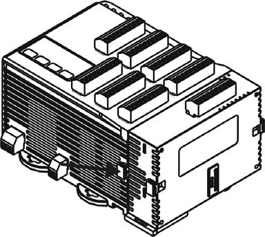
2 Specifications Power input Voltage range 24 VDC, isolated switching power supply 90 to 110% rated voltage Power consumption Max. 10 W + 3 W number of DTC2000 controllers connected in parallel (Max. 7) Input sensor Sampling cycle Control method Output accessories (optional) Output functions Alarm modes Communication Communication protocol Extension port Thermocouple: K, J, T, E, N, R, S, B, L, U, TXK Platinum resistance: Pt100, JPt100, Cu50 Thermocouple or platinum resistance: 1.0 second/all input PID, PID programmable, manual, / Relay output: SPST, Max. 250 VAC load, 3 A resistive load Voltage pulse output: 12 VDC, Max. 40 ma current output Current output: DC 4 to 20 ma output (resistive load < 500Ω); for OUT1 and OUT2 only Analog voltage output: 0 to 10V (resistive load > 1,000Ω); for OUT1 and OUT2 only Control output, alarm output or proportional output (proportional output is only applicable in the model with linear voltage and current output for OUT1, OUT2) 13 alarm modes available RS-485 digital communication; supports baudrate 2,400 to 115,200bps Supports Modbus ASCII/RTU The extension port transmits 24V power supply and communication signals to extension module DTC2000. Vibration resistance 10 to 55Hz 10m/s 2 3 axes 10mins Shock resistance Max. 300m/s 2 3 axes 6 directions, 3 times each Ambient temperature Storage temperature 0 to +50 C -20 to +65 C Operation altitude < 2,000m Ambient humidity Pollution degree 2 35 to 85% RH (non-condensing) Product Profile & Outline DTE10T 1 I/O terminals 2 Status LED 3 Display and setup unit 4 DIN rail clip 5 Power input port 6 RS-485 communication port 7 Extension module fixing clip 8 Extension port Panel Layout - 2 -
3 Input The standard DTE main unit is attached with 4 channels of inputs. You can purchase additional DTE20T or DTE20P to expand the number of input channels. DTE supports maximum 8 channels of inputs which belong to group INA and group INB. Each group possesses 4 input channels. DTE series supports the following input sensors: Input Sensor Type Register Value Range For DTE10P / DTE20P Temperature measurement resistance (Cu50) ~ 150 C Platinum resistance (Pt100) ~ 600 C Platinum resistance (JPt100) ~ 400 C For DTE10T / DTE20T Thermocouple TXK type ~ 800 C Thermocouple U type ~ 500 C Thermocouple L type ~ 850 C Thermocouple B type ~ 1,800 C Thermocouple S type 6 0 ~ 1,700 C Thermocouple R type 5 0 ~ 1,700 C Thermocouple N type ~ 1,300 C Thermocouple E type 3 0 ~ 600 C Thermocouple T type ~ 400 C Thermocouple J type ~ 1,200 C Thermocouple K type ~ 1,300 C Note: The default setting in DTE10T is thermocouple K type. The default setting in DTE10P is Pt100". Communication address: Input sensor types at H10A0 ~ H10A7; input upper limits at H1010 ~ H1017; input lower limits at H1018 ~ H101F. Output DTE supports maximum 16 channels of outputs, belonging to output groups OUT1, OUT2, SUB1 and SUB2, each group with 4 channels. See the explanations below for how input channels correspond to output groups. Without group INB (4 channels of input): Every channel corresponds to 2 groups of output and 2 groups of alarms. OUT1 and SUB1 are for control output, and OUT1 can be used for proportional output. OUT2 and SUB2 are fixed for alarm output. With group INB (8 channels of input): Every channel is paired with 2 groups of outputs. OUT1 and OUT2 are used for control output or proportional output of CH1 ~ CH8. SUB1 and SUB2 are used for control output or alarm output. See Table 1 for the relations between input and output. 4 channels of input 8 channels of input Output Group INA (CH1 ~ CH4) INA (CH1 ~ CH4) INB (CH5 ~ CH8) OUT1 Main control output or proportional output Main control output or proportional output No corresponding output OUT2 Alarm 1 output No corresponding output Main control output or proportional output SUB1 Control output Control output or alarm output No corresponding output SUB2 Alarm 2 output No corresponding output Control output or alarm output Table 1 Note: SUB1 and SUB2 do not support DTE20L and DTE20C. Please install the optional output modules you purchase into the correct slot. Communication Address of Output & How to Set up Parameters See Table 2 for the communication addresses of output and Table 3 for the definition of the value in the address. INA INB CH1 CH2 CH3 CH4 CH5 CH6 CH7 CH8 OUT1, OUT2 H10A8 H10A9 H10AA H10AB H10AC H10AD H10AE H10AF SUB1, SUB2 H10B0 H10B1 H10B2 H10B3 H10B4 H10B5 H10B6 H10B7 Table 2-3 -
4 Value = 0 Value = 1 Value = 2 Value = 3 OUT1, OUT2** Heating control Cooling control Proportional output Disable output SUB1, SUB2** Heating control Cooling control Alarm output* Disable output Table 3 *When there are only 4 channels of inputs, SUB1 cannot be used for alarm output but heating/cooling control only. **When there are only 4 channels of inputs, OUT2 and SUB2 cannot be set up by the user but set up automatically as "alarm output by the controller. Control Output DTE offers PID control, / control, manual control and programmable PID control. Control output methods are set at address H10B8 ~ H10BF (default = 0: PID), PID parameters at H1028 ~ H105F, / parameters at H1058 ~ H106F, and manual control parameters at H1070 ~ H107F. Alarm Output DTE offers 13 alarm modes. The alarm modes are set up at address H10C0 ~ H10C7, upper limits at H1080 ~ H1087 and lower limits at H1088 ~ H108F. SV Alarm Mode Alarm Output Operation 0 No alarm Off Alarm output is enabled when the temperature reaches upper and lower limits: The alarm 1 will be enabled when PV exceeds SV + AL-H or falls below SV AL-L. AL-L SV AL-H 2 3 Alarm output will be enabled when the temperature reaches the upper limit: The alarm will be enabled when the PV exceeds SV + AL-H. Alarm output will be enabled when the temperature reaches the lower limit: The alarm will be enabled when the PV falls below SV AL-L. 4 Alarm output will be enabled when the PV is between SV + AL-H and SV AL-L Alarm output will be enabled when the temperature reaches the absolute value of the upper and lower limits: The alarm will be enabled when the PV exceeds AL-H or falls below AL-L. Alarm output will be enabled when the temperature reaches the absolute value of the upper limit: The alarm will be enabled when the PV exceeds AL-H. Alarm output will be enabled when the temperature reaches the absolute value of the lower limit: The alarm will be enabled when the PV falls below AL-L. Upper/lower limit standby alarm: The alarm will be enabled when the PV reaches SV and further exceeds SV + AL-H or falls below SV AL-L. Upper limit standby alarm: The alarm will be enabled when the PV reaches SV and further exceeds SV + AL-H. Lower limit standby alarm: The alarm will be enabled when the PV reaches SV and further falls below SV AL-L. Upper limit hysteresis alarm: The alarm will be enabled when the PV exceeds SV + AL-H. The alarm will be disabled when the PV falls below SV + AL-L. AL-L SV SV AL-H AL-L SV AL-H AL-L AL-H AL-L AL-L SV AL-L SV AL-H AL-H SV AL-H AL-L AL-H Lower limit hysteresis alarm: The alarm will be enabled when the PV falls below SV AL-H. The alarm will be disabled when the PV exceeds SV AL-L. CT alarm: The alarm will be enabled when the CT value exceeds AL-H or falls below AL-L. AL-H AL-L AL-L AL-H - 4 -
5 LED Display PWR: On DTE is powered. RUN: On Any of the channel is executing. COM: Flashing Communication in progress ERR: Indicating errors (red) ERR LED is on indicates one of the following errors occur, and the output has to be disabled. 1. Memory EEPROM error. 2. Any of the input points is not connected. 3. Any of the input points exceeds the setup range. 4. Any of the input temperatures has not been stabilized. Synchronous Communication Protocol & Auto ID Setup This function allows the auto setup of communication protocol in extension module DTC2000 and DTC2001 following the communication protocol set in the DTE main unit. The station IDs of DTC decrease. See below for the steps. 1. Set the auto communication ID of DTE as 1 (communication address: H10F8). 2. Switch off DTE. Connect DTE with extension module DTC2000, DTC2001 and switch on DTE again. 3. Default communication protocol: 9,600bps, 7 bits, Even, 1 stop bit, communication address = This function will consume 3 ~ 5 seconds more when you switch on DTE. CT (Current Transformer) Function DTE10T offers maximum 4 channels of CT (CT1 ~ CT4), responsible for monitoring the current in INA. Each CT group can be set up independently. With alarm outputs, when the detected current value is beyond the allowed range, the corresponding alarm will be enabled. Slot INA offers 4 channels of input, and CH1 ~ CH4 correspond to the current detected at CT1 ~ CT4. Hardware requirement: Accessory DTE2CT inserted in the slot AUX. How to Operate 1. Enable the CT function: Write 1234H into the address 47F1H and then 0004H into address 4824H. bits in 4824H Bit7 Bit6 Bit5 Bit4 Bit3 Bit2 Bit1 Bit0 Flag -- Hot runner control Slope control -- Latch CT EVENT -- Notes: The flag to enable CT is at bit2 of 4824H. Write 0004H to bit2 to set it on. If the multistate function is enabled, for example, writing in 0024H means enabling bit5 and bit2 at the same time. You can only choose to use either the CT or EVENT function. If there is already a set value in 4824H and you would like to modify it, reset it to 0 before you set up a new value. 2. When you use INA input or INA + INB input, set up relevant parameters using the table below. INA input: INA CH1 CH2 CH3 CH4 OUT1 control mode 10A8H 10A9H 10AAH 10ABH OUT2 control mode 10B0H 10B1H 10B2H 10B3H Alarm 1 output mode 10C0H 10C1H 10C2H 10C3H Alarm 2 output mode 10C4H 10C5H 10C6H 10C7H Upper bound of Alarm 1 output 1080H 1081H 1082H 1083H Lower bound of Alarm 1 output 1088H 1089H 108AH 108BH Upper bound of Alarm 2 output 1084H 1085H 1086H 1087H Lower bound of Alarm 2 output 108CH 108DH 108EH 108FH CT value (latch) 19A0H 19A1H 19A2H 19A3H CT value (dynamic) 19A4H 19A5H 19A6H 19A7H - 5 -
6 INA + INB input: INA+INB CH1 CH2 CH3 CH4 CH5 CH6 CH7 CH8 OUT1 control mode 10A8H 10A9H 10AAH 10ABH 10ACH 10ADH 10AEH 10AFH Alarm 1 output mode 10C0H 10C1H 10C2H 10C3H 10C4H 10C5H 10C6H 10C7H Upper bound of Alarm 1 output 1080H 1081H 1082H 1083H 1084H 1085H 1086H 1087H Lower bound of Alarm 1 output 1088H 1089H 108AH 108BH 108CH 108DH 108EH 108FH CT value (latch) 19A0H 19A1H 19A2H 19A3H CT value (dynamic) 19A4H 19A5H 19A6H 19A7H OUT1 control mode has to be set to 0 (heating) or 1 (cooling). It cannot be set to 2 (proportional output). 4. You can select Alarm 1 or Alarm 2 to be the output contact. The output mode has to be set to 13 (000DH). 5. Adjust the upper/lower bound of the alarm output. 6. The CT value will only be measured when there is OUT1 executing. If OUT1 does not exist, the previous CT value measured will be displayed. EVENT Input Function DTE10T offers 8 channels of EVENT input (EV1 ~ EV8), and each EVENT can be set up independently. Slot number 1 ~ 8 in AUX on DTE10T correspond to EV1 ~ EV8. EV1 to EV8 can be short-circuited individually with slot number 9 to switch functions. Hardware requirement: Accessory DTE20D inserted in the slot AUX. How to Operate 1. Enable the EVENT function: Write 1234H into the address 47F1H and then 0002H into address 4824H. bits in 4824H Bit7 Bit6 Bit5 Bit4 Bit3 Bit2 Bit1 Bit0 Flag -- Hot runner control Slope control -- Latch CT EVENT -- Notes: The flag to enable EVENT is at bit1 of 4824H. Write 0002H to bit1 to set it on. If the multistate function is enabled, for example, writing in 0022H means enabling bit5 and bit1 at the same time. You can only choose to use either the CT or EVENT function. If there is already a set value in 4824H and you would like to modify it, reset it to 0 before you set up a new value. 2. Each channel can be set up individually for specific functions. Addresses: CH CH1 CH2 CH3 CH4 CH5 CH6 CH7 CH8 Address for the 1998H 1999H 199AH 199BH 199CH 199DH 199EH 199FH EVENT function Functions: Set value Function N/A RUN (open circuit) STOP (short circuit) SV1 (open circuit) SV2 (short circuit) Auto (open circuit) Manual (short circuit) Definitions: RUN/STOP: To enable or disable the output. SV1/SV2: To switch between set values. Auto/manual: To switch between the PID and manual controls. Execute/pause: To execute or pause the counting time when in programmable PID control. Example: If you would like the function of EVENT1 at CH1 to be SV1/SV2, write 0002H into address 1998H. Slope Function Execute (open circuit) Pause (short circuit) The temperature rises according to the slope set. Unit: 0.1 C/min. Example: Suppose the slope is set to 50 and SV C, then the temperature will rise at 5 C per minute until it reaches C
7 How to Operate 1. Enable the slope function: Write 1234H into the address 47F1H and then 0020H into address 4824H. bits in 4824H Bit7 Bit6 Bit5 Bit4 Bit3 Bit2 Bit1 Bit0 Flag -- Hot runner control Slope control -- Latch CT EVENT -- Notes: The flag to enable slope function is at bit5 of 4824H. Write 0020H to bit5 to set it on. If the multistate function is enabled, for example, writing 0022H means enabling bit5 and bit1 at the same time. If there is already a set value in 4824H and you would like to modify it, reset it to 0 before you set up a new value. 2. Set up relevant parameters using the table below. CH CH1 CH2 CH3 CH4 CH5 CH6 CH7 CH8 Set value (SV) 1008H 1009H 100AH 100BH 100CH 100DH 100EH 100FH Slope (unit: 0.1 ) 1970H 1971H 1972H 1973H 1974H 1975H 1976H 1977H Note: To stabilize the control, first execute auto-tuning when the slope function is selected. When auto-tuning is being executed, the slope control will stop. Programmable PID Latch Function Function DTE10T offers programmable PID latch function. When the power is off and on again, the status before the power is cut off can be retained. How to Operate 1. Enable the programmable PID latch function: Write 1234H into the address 47F1H and then 0008H into address 4824H. bits in 4824H Bit7 Bit6 Bit5 Bit4 Bit3 Bit2 Bit1 Bit0 Flag -- Hot runner control Slope control -- Latch CT EVENT -- Notes: The flag to enable PID latch is at bit3 of 4824H. Write 0008H to bit3 to set it on. If the multistate function is enabled, for example, writing in 0028H means enabling bit5 and bit3 at the same time. If there is already a set value in 4824H and you would like to modify it, reset it to 0 before you set up a new value. Opposite Output Function The 8 channels on DTE10T can be set to opposite output, that is, when the output is set to 0, the actual output will be 1. How to Operate To set CH1 and CH3 to opposite output, first write 1234H into the address 47F1H and then 0005H into address 4821H to set on CH1 (bit0) and CH3 (bit2). CH8 CH7 CH6 CH5 CH4 CH3 CH2 CH1 Bit7 Bit6 Bit5 Bit4 Bit3 Bit2 Bit1 Bit0 Delayed Alarm Function When the set condition for alarms is met, the alarm will be enabled after a pre-set period of time. How to Operate Set up the time using the table below. Unit: second CH CH1 CH2 CH3 CH4 CH5 CH6 CH7 CH8 Address for delayed alarm 1990H 1991H 1992H 1993H 1994H 1995H 1996H 1997H - 7 -
8 Output Limits Function The output is limited between the maximum and minimum percentages. How to Operate Set up relevant parameters using the table below. CH CH1 CH2 CH3 CH4 CH5 CH6 CH7 CH8 Max. output (%) 1980H 1981H 1982H 1983H 1984H 1985H 1986H 1987H Min. output (%) 1988H 1989H 198AH 198BH 198CH 198DH 198EH 198FH Note: When the output volume is limited at 20 to 80%, it means the output volume 0 to 100% calculated by the controller is corresponding to the actual output 20 to 80%. Programmable Control Time Unit Function The unit of programmable control time can be minute or second. How to Operate Write 0 to the address to set the time unit to minute (default) or write 1 to set it to second. CH CH1 CH2 CH3 CH4 CH5 CH6 CH7 CH8 Address for time unit 1978H 1979H 197AH 197BH 197CH 197DH 197EH 197FH Input Filter Function To avoid unstable PV display due to interferences, DTE10T offers the filter function. Instead of averaging the values, the filter function here calculate the weighted average value of the current PV and previous PV. The filter equation: PV (displayed value) = [previous PV x (filter times 1) + current PV] / filter times The bigger the filter times, the bigger the weight of the previous PV, and the smoother the temperature display, which is a good way to suppress interferences. How to Operate Set up relevant parameters using the table below. Parameter Address Default value Range Filter times 10F7H 8 0 ~ 50 Filter range 10F9H ~ 10.0 Hot Runner Control Function The hot runner control includes 3 steps: 1. Heating up by constant output volume 2. Timed PID control (Soak) 3. Slope heating to the target temperature (SV) How to Operate 1. Enable the hot runner control function: Write 1234H into the address 47F1H and then 0060H into address 4824H. bits in 4824H Bit7 Bit6 Bit5 Bit4 Bit3 Bit2 Bit1 Bit0 Flag -- Hot runner control Slope control -- Latch CT EVENT -- Notes: The flag to enable hot runner control is at bit6 of 4824H (and bit5 as to be enabled at the same time). Write 0060H to set both bits on
9 If there is already a set value in 4824H and you would like to modify it, reset it to 0 before you set up a new value. 2. Set up relevant parameters using the table below. CH CH1 CH2 CH3 CH4 CH5 CH6 CH7 CH8 Temp. bound (unit: 0.1 ) 1960H 1961H 1962H 1963H 1964H 1965H 1966H 1967H Constant output volume (unit: 0.1%) 1968H 1969H 196AH 196BH 196CH 196DH 196EH 196FH Timed time (unit: min.) 19B0H 19B1H 19B2H 19B3H 19B4H 19B5H 19B6H 19B7H Target temperature (unit: 0.1 ) 1008H 1009H 100AH 100BH 100CH 100DH 100EH 100FH Slope (unit: 0.1 ) 1970H 1971H 1972H 1973H 1974H 1975H 1976H 1977H Example Assume the temperature bound is 100.0, constant output volume is 35.0, timed time is 15, target temperature is and slope is 20.0, thus 1. The heater outputs by the 35% constant volume and waits for the temperature to rise to 100 degrees, 2. When the temperature hits 100 degrees, switch to the PID soak mode and retain the temperature constantly for 15 minutes. 3. When the time is up, switch to the slope control mode, executing the condition of a 20 degree temperature rise every minute. 4. When the heating achieves 200 degrees, the hot runner control is completed. RS-485 Communication 1. DTE supports baudrates 2,400/4,800/9,600/19,200/38,400/57,600/115,200 bps and does not support communication format 7, N, 1/8, E, 2/8, O, 2. Communication protocol = Modbus ASCII or RTU. 2. Function codes: H03 = read maximum 8 words in the register; H06 = write 1 word into the register. 3. Address and contents: Every parameter has 2 communication addresses. One is numbered by the function of the parameter, and the other is by the order of channel (as shown in the table below). INA INB Content Explanation CH1 CH2 CH3 CH4 CH5 CH6 CH7 CH8 Present temperature value/input error code Unit; 0.1 See Table 5 Set temperature value Unit: 0.1 Max. temperature value Min. temperature value Error temperature value Proportional band value (Pb) Disabled when higher than default value Disabled when lower than default value -999 ~ +999 Unit: 0.1 C 0 ~ 9,999 Unit: 0.1 Ti value 0 ~ 9,999 Td value 0 ~ 9,999 Integration default Proportional control offset error value, when Ti = 0 Proportional band coefficient of output 1 and output 2 Dead band of control output 1 & output 2. Hysteresis for output 1 Hysteresis for output ~ 100.0% Unit: 0.1% 0.0 ~ 100.0% Unit: 0.1% 0.01 ~ Unit: ~ ~ 9,999 Unit: 0.1% 0 ~ 9,999 Unit: 0.1% H1000 (H1100) H1008 (H1101) H1010 (H1102) H1018 (H1103) H1020 (H1104) H1028 (H1105) H1030 (H1106) H1038 (H1107) H1040 (H1108) H1048 (H1109) H1050 (H110A) H1058 (H110B) H1060 (H110C) H1068 (H110D) H1001 (H1200) H1009 (H1201) H1011 (H1202) H1019 (H1203) H1021 (H1204) H1029 (H1205) H1031 (H1206) H1039 (H1207) H1041 (H1208) H1049 (H1209) H1051 (H120A) H1059 (H120B) H1061 (H120C) H1069 (H120D) H1002 (H1300) H100A (H1301) H1012 (H1302) H101A (H1303) H1022 (H1304) H102A (H1305) H1032 (H1306) H103A (H1307) H1042 (H1308) H104A (H1309) H1052 (H130A) H105A (H130B) H1062 (H130C) H106A (H130D) H1003 (H1400) H100B (H1401) H1013 (H1402) H101B (H1403) H1023 (H1404) H102B (H1405) H1033 (H1406) H103B (H1407) H1043 (H1408) H104B (H1409) H1053 (H140A) H105B (H140B) H1063 (H140C) H106B (H140D) H1004 (H1500) H100C (H1501) H1014 (H1502) H101C (H1503) H1024 (H1504) H102C (H1505) H1034 (H1506) H103C (H1507) H1044 (H1508) H104C (H1509) H1054 (H150A) H105C (H150B) H1064 (H150C) H106C (H150D) H1005 (H1600) H100D (H1601) H1015 (H1602) H101D (H1603) H1025 (H1604) H102D (H1605) H1035 (H1606) H103D (H1607) H1045 (H1608) H104D (H1609) H1055 (H160A) H105D (H160B) H1065 (H160C) H106D (H160D) H1006 (H1700) H100E (H1701) H1016 (H1702) H101E (H1703) H1026 (H1704) H102E (H1705) H1036 (H1706) H103E (H1707) H1046 (H1708) H104E (H1709) H1056 (H170A) H105E (H170B) H1066 (H170C) H106E (H170D) H1007 (H1800) H100F (H1801) H1017 (H1802) H101F (H1803) H1027 (H1804) H102F (H1805) H1037 (H1806) H103F (H1807) H1010 (H1808) H104F (H1809) H1057 (H180A) H105F (H180B) H1067 (H180C) H106F (H180D) - 9 -
10 INA INB Content Explanation CH1 CH2 CH3 CH4 CH5 CH6 CH7 CH8 Read/write output 1 value Unit: 0.1 % Read/write output 2 value Unit: 0.1 % Upper limit for alarm output Lower limit for alarm output Tuning for upper limit of analog output Tuning for lower limit of analog output Input sensor type Output function for output 1 Output function for output 2 Control method Alarm 1 output mode Alarm 2 output mode Heating/cooling cycle for output 1 Heating/cooling cycle for output 2 Run/Stop the control Status of PID auto-tuning Positive/negative proportional output Other statuses Communication specifications LED status Alarm enabled when temperature exceeds upper limit Alarm enabled when temperature falls below lower limit Current (4 ~ 20mA) or voltage output tuning Current (4 ~ 20mA) or voltage output tuning See Input section 0: heating 1: cooling 2: proportional output 0: heating (default) 1: cooling 2: alarm 0: PID 1: - 2: manual 3: PID programmable See Alarm Output section See Alarm Output section 1 ~ 99 seconds 0 = 0.5 second 1 ~ 99 seconds 0 = 0.5 second 0: stop 1: executing 2: program stops 3: program pauses 0: stop 1: executing 0: positive 1: negative (slope) Other statuses See Table 4 b1: Alarm 2; b2: C; b3: F; b4: Alarm 1; b5: OUT2; b6: OUT1; b7: AT H1070 (H110E) H1078 (H110F) H1080 (H1110) H1088 (H1111) H1090 (H1112) H1098 (H1113) H10A0 (H1114) H10A8 (H1115) H10B0 (H1116) H10B8 (H1117) H10C0 (H1118) H10C4 (H1518) H10C8 (H1119) H10D0 (H111A) H10D8 (H111B) H10E0 (H111C) H10E8 (H111D) H10F0 Temperature unit H10F8 Auto ID setup H1071 (H120E) H1079 (H120F) H1081 (1210) H1089 (H1211) H1091 (H1212) H1099 (H1213) H10A1 (H1214) H10A9 (H1215) H10B1 (H1216) H10B9 (H1217) H10C1 (H1218) H10C5 (H1618) H10C9 (H1219) H10D1 (H121A) H10D9 (H121B) H10E1 (H121C) H10E9 (H121D) H10F1 Open special function (H1234) H10F9 Reserved H1072 (H130E) H107A (H130F) H1082 (H1310) H108A (H1311) H1092 (H1312) H109A (H1313) H10A2 (H1314) H10AA (H1315) H10B2 (H1316) H10BA (H1317) H10C2 (H1318) H10C6 (H1718) H10CA (H1319) H10D2 (H131A) H10DA (H131B) H10E2 (H131C) H10EA (H131D) H10F2 Return to default (H1357) H10FA Baudrate H1073 (H140E) H107B (H140F) H1083 (H1410) H108B (H1411) H1093 (H1412) H109B (H1413) H10A3 (H1414) H10AB (H1415) H10B3 (H1416) H10BB (H1417) H10C3 (H1418) H10C7 (H1818) H10CB (H1419) H10D3 (H141A) H10DB (H141B) H10E3 (H141C) H10EB (H141D) H10F3 Reserved H10FB ASCII = 0 RTU = 1 H1074 (H150E) H107C (H150F) H1084 (H1510) H108C (H1511) H1094 (H1512) H109C (H1513) H10A4 (H1514) H10AC (H1515) H10B4 (H1516) H10BC (H1517) H10C4 (H1518) H10CC (H1519) H10D4 (H151A) H10DC (H151B) H10E4 (H151C) H10EC (H151D) H10F4 Reserved H10FC 8 bits=0 7 bits=1 H1075 (H160E) H107D (H160F) H1085 (H1610) H108D (H1611) H1095 (H1612) H109D (H1613) H10A5 (H1614) H10AD (H1615) H10B5 (H1616) H10BD (H1617) H10C5 (H1618) H10CD (H1619) H10D5 (H161A) H10DD (H161B) H10E5 (H161C) H10ED (H161D) H10F5 Reserved H10FD 2 stop=0 1 stop=1 H1076 (H170E) H107E (H170F) H1086 (H1710) H108E (H1711) H1096 (H1712) H109E (H1713) H10A6 (H1714) H10AE (H1715) H10B6 (H1716) H10BE (H1717) H10C6 (H1718) H10CE (H1719) H10D6 (H171A) H10DE (H171B) H10E6 (H171C) H10EE (H171D) H10F6 Reserved H10FE Parity H1077 (H180E) H107F (H180F) H1087 (H1810) H108F (H1811) H1097 (H1812) H109F (H1813) H10A7 (H1814) H10AF (H1815) H10B7 (H1816) H10BF (H1817) H10C7 (H1818) H10CF (H1819) H10D7 (H181A) H10DF (H181B) H10E7 (H181C) H10EF (H181D) H10F7 Reserved H10FF Address 1 ~ 247 H1124 H1224 H1324 H1424 H1524 H1624 H1724 H
11 Communication Parameter Setting Content Baudrate 2,400bps 4,800bps 9,600bps 19,200bps 38,400bps 57,600bps 115,200bps Parity bit None (N) Even (E) Odd (O) Error Codes Table 4 The error codes can be read from address H1000 ~ H1007. When the input operation is in normal status, H1000 ~ H1007 are for input values. When input error occurs (except for stable status and input exceeding the range), DTE will read error codes in H8001 ~ H8002. H1000 H8001 H8002 H8003 Error description EEPROM cannot be written in. Input sensor is not connected. Group INB is not connected. Table 5 Analog output current tuning scale: 1μA/scale Analog output voltage tuning scale: 1mV/scale Returning to Default Value: Write H1234 into address H10F1 and H1357 into address H10F2. Restart DTE. Programmable Communication Parameter Setting INA INB Content Explanation CH1 CH2 CH3 CH4 CH5 CH6 CH7 CH8 Read remaining time of the step Unit: sec H111E H121E H131E H141E H151E H161E H171E H181E Read remaining time of the step Unit: min H111F H121F H131F H141F H151F H161F H171F H181F Read the NO. of the current pattern 0 ~ 7 H1120 H1220 H1320 H1420 H1520 H1620 H1720 H1820 Read the NO. of the current step 0 ~ 7 H1121 H1221 H1321 H1421 H1521 H1621 H1721 H1821 NO. of start pattern 0 ~ 7 H1122 H1222 H1322 H1422 H1522 H1622 H1722 H1822 NO. of start step 0 ~ 7 H1123 H1223 H1323 H1423 H1523 H1623 H1723 H1823 Programmable Parameter Setting Content Explanation Pattern 0 Pattern 1 Pattern 2 Pattern 3 Pattern 4 Pattern 5 Pattern 6 Pattern 7 Max. number of steps in the pattern Number of cycles of pattern 0 ~ 7 execution NO. of current link pattern 0 ~ 7 = N: The pattern executes from step 0 to N. 0 ~ 199: The pattern has been executed for 1 ~ 200 times 0 ~ 8: 8 refers to end of program; 0 ~ 7 refer to the NO. of next pattern H2068 H2069 H206A H206B H206C H206D H206E H206F H2070 H2071 H2072 H2073 H2074 H2075 H2076 H2077 H2078 H2079 H207A H207B H207C H207D H207E H207F Address Default Content Explanation 2000H ~ 203FH H ~ 20BFH 0 Target temperatures for pattern 0 ~ 7 Pattern 0: 2000H ~ 2007H Execution time for pattern 0 ~ 7 Pattern 0: 2080H ~ 2087H Unit: 0.1 C Time: 0 ~ 900 (Unit: 1 min) 4. Communication format: H03 = read bit data; H06 = write bit data
12 ASCII Mode Read Command Read Response Message Write Command Write Response Message Start word : Start word : Start word : Start word : Machine address 1 0 Machine address 1 0 Machine address 1 0 Machine address 1 0 Machine address 0 1 Machine address 0 1 Machine address 0 1 Machine address 0 1 Command 1 0 Command 1 0 Command 1 0 Command 1 0 Command 0 3 Command 0 3 Command 0 6 Command Length of response data (byte) Read start address of Data address Data address data/bit Data content in H F 0 0 Read length of data/bit Write data content Write data content (word/bit) 0 0 E E Data content in H1001 LRC1 check E 0 LRC1 check F LRC1 check F LRC0 check A 0 LRC0 check D LRC0 check D End word 1 CR LRC1 check 0 End word 1 CR End word 1 CR End word 0 LF LRC0 check 3 End word 0 LF End word 0 LF End word 1 CR End word 0 LF LRC Check Sum up the contents from machine address to data content, e.g. H01 + H03 + H10 + H00 + H00 + H02 = H16. Obtain 2 scomplement H EA. RTU Mode Read Command Read Response Message Write Command Write Response Message Machine address H01 Machine address H01 Machine address H01 Machine address H01 Command H03 Command H03 Command H06 Command H06 Read start address of data Read length of data (bit/word) H10 Length of response data H10 H10 H04 Write data address Write data address H00 (byte) H01 H01 H00 H01 H03 H03 Data content 1 Write data content Write data content H02 HF4 H20 H20 CRC low byte HC0 H03 CRC low byte HDD CRC low byte HDD Data content 2 CRC high byte HCB H20 CRC high byte HE2 CRC high byte HE2 CRC low byte HBB CRC high byte H15 CRC (Cyclical Redundancy Check) is obtained by the following steps: unsigned int reg_crc = 0xffff; i = 0; while (length--) { reg_crc ^= RTUData[i]; i ++; for (j = 0; j < 8; j++) { if (reg_crc & 0x01) reg_crc = (reg_crc >> 1) ^ 0xA001; else reg_crc = reg_crc >> 1; } } return(reg_crc); Software for Setting up Communication on PC: Download the free software on Delta s website


13 How to Mount & DIN Rail Size Connect maximum 7 DTC2000 or DTC2001 controllers to DTE by using DIN rail
Series Digital Controller Instruction Sheet
 216/3/11 Series Digital Controller Instruction Sheet Thank you very much for purchasing DELTA DTC Series Temperature Controller. Please read this instruction sheet before using your DTC series to ensure
Series Temperature Controller Instruction Sheet
 Series Temperature Controller Instruction Sheet Thank you very much for purchasing DELTA A Series. Please read this instruction sheet before using your A series to ensure proper operation and please keep
+ A B V B NO NC V COM PV PV
 + - A + B B - V + - NO NC COM + - + - V + - PV PV Ramp Soak 100 70 50 30 3 5 3 8 5 3 Minute Steam Heating Sensor Cooling Water PID Hotplate Specifications Input power supply AC 100 to 240V, 50/60Hz, DC
Temperature Controllers
 Model TEC-4100 1/4 DIN Model TEC-4100 1/4 DIN Temperature Controller Ordering Code: Power Input BOX 1 4 = 90-250 VAC 5 = 11-26 VAC / VDC TEC-4100- Configurable for 4 Programmable Outputs and NEMA 4X/IP65
370, boulevard de Balmont LYON Tel Fax Web:
 AUTOMATISME Régulateurs de température delta DELTA développe, dessine, fabrique des composants et des équipements électronique pour les plus importants constructeurs internationaux. Fort de ses 30.000
Serie Rugghölzli 2 CH Busslingen. Tel. +41 (0) Fax +41 (0)
 Fax +41 (0)") Serie 5000 Tel. +1 (0)5 222 Fax +1 (0)5 222 12 PRODUCT INTRODUCTI PRODUCT INTRODUCTI 5 Series programmable temperature controller is FineTek's mid-range series of controllers. It uses a 12bit analog /
Serie 5000 Tel. +1 (0)5 222 Fax +1 (0)5 222 12 PRODUCT INTRODUCTI PRODUCT INTRODUCTI 5 Series programmable temperature controller is FineTek's mid-range series of controllers. It uses a 12bit analog /
Communications* None RS-232C RS-422 RS-485 BCD Transmission output** (4 to 20 ma)
") TEMPERATURE CONTROLLER DIN-sized (96 x 96-mm) Temperature Controller Featuring Advanced PID Control and Heater Burnout Detection Advanced PID control with two degrees of freedom to improve stability and
TEMPERATURE CONTROLLER DIN-sized (96 x 96-mm) Temperature Controller Featuring Advanced PID Control and Heater Burnout Detection Advanced PID control with two degrees of freedom to improve stability and
RS485 MODBUS Module 8AI
 Version 1.4 15/04/2013 Manufactured for Thank you for choosing our product. This manual will help you with proper support and proper operation of the device. The information contained in this manual have
Temperature Controller
 E5AN Temperature Controller Temperature Controller OMRON Corporation Industrial Automation Company Industrial Devices and Components Division H.Q. Measuring Components Department Shiokoji Horikawa, Shimogyo-ku,
TEMPERATURE CONTROL MODULE MODEL R3-TC2
 INSTRUCTION MANUAL R3-TC2 TEMPERATURE CONTROL MODULE MODEL R3-TC2 CONTENTS BEFORE USE... 2 POINTS OF CAUTION... 2 COMPONENT IDENTIFICATION... 2 INSTALLATION... 2 EXTERNAL DIMENSIONS unit: mm (inch)...
INSTRUCTION MANUAL Micro-computer based digital indicating controller
 INSTRUCTI MANUAL Micro-computer based digital indicating controller TP4A To prevent accidents arising from the misuse of this controller, please ensure the operator using it receives this manual. Caution
Micro-controller X C C1 C2 AL1 AL2 AL3. Model: PXR4/5/9. Operation Manual SEL PXR. ECNO:406e
 C C1 C2 AL1 AL2 AL3 Micro-controller X Model: PXR4/5/9 PXR SEL Operation Manual ECNO:46e Table of Contents Part Names and Functions... 6 Operations... 7 2-1 Parameter list... 7 2-2 Basic operations...
Communications None RS-232C RS-422* RS-485* BCD Transmission output*/** (4 to 20 ma) E5AX- E5AX- L(M)A02 L(M)A03
 E5AX- E5AX- L(M)A02 L(M)A03") Digital Controller A 96 x 96-mm (DIN) Digital Process Controller Optimum PID control with feed-forward control circuitry. High accuracy (+0.3% FS +1 digit max.). Replaceable Output Units. Models with communications
Digital Controller A 96 x 96-mm (DIN) Digital Process Controller Optimum PID control with feed-forward control circuitry. High accuracy (+0.3% FS +1 digit max.). Replaceable Output Units. Models with communications
F4 Process Controller Installation and Operation Guide
 F4 Process Controller Installation and Operation Guide 1.Introduction 1.1.Highlight Features Space saving, only 55mm panel depth required Higher sampling rate (1mS) results in better control performance
TEMPERATURE CONTROLLER
 TEMPERATURE CONTROLLER E5CX(-H) DIN-sized super-compact (48 x 48-mm) Temperature Controller Featuring Advanced PID Control Advanced PID control with two degrees of freedom improves stability and response
Instruction manual Micro-computer based digital indicating controller
 Instruction manual Micro-computer based digital indicating controller JCS-33A To prevent accidents arising from the misuse of this controller, please ensure the operator using it receives this manual.
VERTEX VT10 SERIES PID OPERATION MANUAL MICROPROCESSOR BASED PID CONTROLLER
 1 VERTEX VT10 SERIES PID OPERATION MANUAL MICROPROCESSOR BASED PID CONTROLLER 1. INTRODUCTION This manual contains information for the installation and operation and tuning of our Vertex VT10 series self-tuning
Instruction manual for DIN rail mounting type indicating controller DCL-33A
 Instruction manual for DIN rail mounting type indicating controller DCL-33A To prevent accidents arising from the misuse of this controller, please ensure the operator using it receives this manual. Caution
02/11/2015
 MIC48 With RS 485 link Part number 89422418 Heating and / or cooling function 2 independent alarms Load break detection 2 setpoint which can be selected remotely Manual / automatic power adjustment RS
Installer Manual KNX Touchscreen Thermostat
 Installer Manual 02952 KNX Touchscreen Thermostat Index GENERAL FEATURES AND FUNCTIONALITY from page 5 ETS PARAMETERS AND COMMUNICATION OBJECTS from page 7 COMMUNICATION OBJECTS GENERAL FEATURES AND FUNCTIONALITY
PROCESS & TEMPERATURE UNIVERSAL INPUT DIGITAL METERS
 PROCESS & TEMPERATURE UNIVERSAL INPUT DIGITAL METERS NOVA PD56 Series Thermocouple, RTD, & Process Inputs Universal Power Supply 1-24 VAC Up to 3 Alarm Relays Retransmitting 4-2 ma Output Input Max/Min
Carbon Monoxide Transmitter
 Introduction The CO Transmitter uses an electrochemical sensor to monitor the carbon monoxide level and outputs a field-selectable 4-20 ma or voltage signal. The voltage signal may also be set to 0-5 or
FL500 Modbus Communication Operating Manual. Order No.: /00. MSAsafety.com
 FL500 Modbus Communication Operating Manual Order No.: 10193214/00 MSAsafety.com 1000 Cranberry Woods Drive Cranberry Township, PA 16066 A Phone 1-800-MSA-2222 Fax 1-800-967-0398 For your local MSA contacts
Process & TeMPerATUre UniversAl input DigiTAl MeTers
 Process & TeMPerATUre UniversAl input DigiTAl MeTers nova PD56 series Thermocouple, rtd, & Process inputs Universal Power supply 1-24 va c Up to 3 Alarm relays retransmitting 4-2 ma output input Max/Min
Instruction manual Temperature Controller KT7
 Instruction manual Temperature Controller KT7 No. KT71E7 201.05 To prevent accidents arising from the misuse of this controller, please ensure the operator receives this manual. SAFETY PRECAUTIS Be sure
02/11/2015
 CTH 46 - CTD 43 / 46 CTD 46 Part number 89422108 CTH 46 Heating / cooling function Measurement and setpoint display CTD 43 Heating or cooling function Measurement display Measurement deviation display-setpoint
4/8/12/16 Channel Temperature Scanner with FREE Data Logging PC Software RS485
 Select Option Device Wise Device/Group HumiLog Y-Axis Text Show/Hide Ledgends MIN MAX Scale Y Max 08-05-2015 15:17:59 PV_C PV_RH Color default default Graph Refresh Interval 2 Set Interval PV Low Alarm
Replaceable LED modules. Sleep or unattended mode. Auto-silence and auto-acknowledge
 Replaceable LED modules 11 Alarm Sequences as per ISA-18.1 standard Each channel/window fully field programmable RS232 or RS485 MODBUS-RTU communication Repeat relay for each window and multifunction relays
Communications type RS-232C RS-422 RS-485 E5AJ-A2H02 E5EJ-A2H02
 Temperature Controller Fuzzy Self-tuning Temperature Controller with Advanced PID (2-PID) Control DIN-size: 6 x 6 mm (E5AJ), 2 x 2 mm (E5BJ), 4 x 4 mm (E5CJ), 4 x 6 mm (E5EJ) Fuzzy self-tuning and Auto-tuning
INSTRUCTION MANUAL FOR MICROCOMPUTER BASED TEMPERATURE INDICATING CONTROLLER FCS-23A
 INSTRUCTION MANUAL FOR MICROCOMPUTER BASED TEMPERATURE INDICATING CONTROLLER Thank you for your purchase of our Microcomputer based Temperature Indicating Controller. This manual contains instructions
Warning Caution INSTRUCTION MANUAL DIN RAIL MOUNTING TYPE INDICATING CONTROLLER
 INSTRUCTI MANUAL DIN RAIL MOUNTING TYPE INDICATING CTROLLER 1 DCL-A DC No.DCLDCE1 2007.01 Thank you for purchasing our DIN rail mounting type indicating controller DCL-A DC. This manual contains instructions
TAIE. Features. FY600 (96mm X 48mm) Application:Control temperature,humidity, FY Series Digital PID Controller
 Application:Control temperature,humidity, FY Series Digital PID Controller") TAIE FY Series Digital PID Controller FY600 (96mm X 48mm) Application:Control temperature,humidity, FY series controllers are microprocessor based controllers. Which have been Designed with high accuracy
TAIE FY Series Digital PID Controller FY600 (96mm X 48mm) Application:Control temperature,humidity, FY series controllers are microprocessor based controllers. Which have been Designed with high accuracy
Safety Instructions MS 10B ALARM UNIT MS 10B ALARM UNIT. Used symbols. Always observe this information to prevent damage to the device
 Safety Instructions Used symbols Important Comments Before starting with installation of the MS 10B Alarm Unit, we recommend you to read the important information beneath. Qualification The installation
INSTRUCTION MANUAL FOR MICROCOMPUTER BASED TEMPERATURE INDICATING CONTROLLER JCD-13A, JCR-13A
 INSTRUCTION MANUAL FOR MICROCOMPUTER BASED TEMPERATURE INDICATING CONTROLLER JCD-13A, JCR-13A Preface Thank you for the purchase of our Microcomputer based Temperature Indicating Controllers JCD-13A or
Tempco Part Number PCT30006 Temperature Control Enclosure with Relay Output for Tote Tank Heating Applications
 Instruction Manual Tempco Part Number PCT30006 Temperature Control Enclosure with Relay Output for Tote Tank Heating Applications Manual PCT30006, Revision 9/20/2016 The PCT30006 control enclosure incorporates
DIGITAL INDICATING CONTROLLER FCS-23A INSTRUCTION MANUAL
 DIGITAL INDICATING CONTROLLER FCS-23A INSTRUCTION MANUAL Preface Thank you for purchasing our Digital indicating controller FCS-23A. This manual contains instructions for the mounting, functions, operations
Tempco PCT-3000 Series Temperature Control Console with Relay Output for Heating or Cooling Applications
 Instruction Manual Tempco PCT-3000 Series Temperature Control Console with Relay Output for Heating or Cooling Applications Manual PCT-3000 Revision 9/2014 The PCT-3000 series control console incorporates
JIR-301-M No.JIR31E To prevent accidents arising from the misuse of this instrument, please ensure the operator receives this manual.
 INSTRUCTION MANUAL MICRO-COMPUTER BASED DIGITAL INDICATOR JIR-31-M No.JIR31E3 24.7 To prevent accidents arising from the misuse of this instrument, please ensure the operator receives this manual. SAFETY
DTSX200 Communications(Modbus) Guide
 Guide") User s Manual DTSX200 Communications(Modbus) Guide 4th Edition Blank Page < Introduction > i Introduction About this Manual Thank you for purchasing the DTSX200 Distributed Temperature Sensor. This document
User s Manual DTSX200 Communications(Modbus) Guide 4th Edition Blank Page < Introduction > i Introduction About this Manual Thank you for purchasing the DTSX200 Distributed Temperature Sensor. This document
EXD-HP1/2 Stand-alone Superheat/Economizer Controller
 Technical Bulletin EXD-HP1/2 are stand-alone universal superheat and or economizer controllers for heat pumps, heating units, air conditioning and precision cooling such as telecom and shelter applications.
TAIE. Features. FY900 (96mm X 96mm) Application:Control temperature,humidity, FY Series Digital PID Controller
 Application:Control temperature,humidity, FY Series Digital PID Controller") TAIE FY Series Digital PID Controller FY900 (96mm X 96mm) Application:Control temperature,humidity, FY series controllers are microprocessor based controllers. Which have been Designed with high accuracy
TAIE FY Series Digital PID Controller FY900 (96mm X 96mm) Application:Control temperature,humidity, FY series controllers are microprocessor based controllers. Which have been Designed with high accuracy
ModSync Sequencing System Installation & Operation Manual. For use with Fulton Steam Boilers.
 ModSync Sequencing System Installation & Operation Manual For use with Fulton Steam Boilers. Revision 3.0 8/21/2008 - 2 - Table of Contents Introduction Page 4 Features Page 4 Sequence of Operation Page
ECO N DATE DESCRIPTION OF CHANGE CHG
 Model Number: M21E-24-DIN Description: The product is a loop powered device which controls an unsupervised dual pole output channel suitable to manage 24VAC loads. The M21E-24-DIN is micro-controller operated,
Cat. No. H113-E1-03B E5ZN. Temperature Controller OPERATION MANUAL
 Cat. No. H113-E1-03B E5ZN Temperature Controller OPERATION MANUAL E5ZN Temperature Controller Operation Manual Revised November 2005 Notice: OMRON products are manufactured for use according to proper
Non-contact voltage (for SSR drive): V DC DC current: 4 to 20mA DC Thermocouple: K, J, E Input. RTD: Pt100, JPt100
: V DC DC current: 4 to 20mA DC Thermocouple: K, J, E Input. RTD: Pt100, JPt100") INSTRUCTI MANUAL Micro-computer based Temperature Indicating Controller 1 GCS-00 No.GCS1E 200.11 To prevent accidents arising from the use of this controller, please ensure the operator receives this manual.
INSTRUCTI MANUAL Micro-computer based Temperature Indicating Controller 1 GCS-00 No.GCS1E 200.11 To prevent accidents arising from the use of this controller, please ensure the operator receives this manual.
OVEN INDUSTRIES, INC.
 OVEN INDUSTRIES, INC. OPERATING MANUAL Model 5C7-252 TEMPERATURE CONTROLLER With PLC Inputs Introduction Thank you for purchasing our controller. The Model 5C7-252 is an exceptionally versatile unit and
FlameGard 5 UV/IR HART
 FlameGard 5 UV/IR HART HART Communication Manual The information and technical data disclosed in this document may be used and disseminated only for the purposes and to the extent specifically authorized
DIGITAL INDICATOR JIR-301-M
 DIGITAL INDICATOR JIR-301-M Instruction Manual Preface Thank you for purchasing our digital indicator JIR-301-M. This manual contains instructions for the mounting, functions, operations and notes when
PLC INTERFACE UNIT CIT-200 INSTRUCTION MANUAL
 PLC INTERFACE UNIT CIT-200 INSTRUCTION MANUAL PREFACE Thank you for the purchase of our PLC Interface Unit CIT-200. This manual contains instructions for the mounting, functions, operations and notes when
OPERATION AND MAINTENANCE MANUAL
 OPERATION AND MAINTENANCE MANUAL Prg Sel line alarm on on/off alarm enter Clear EMIpro MICROPROCESSOR CONTENTS 1 GENERAL CHARACTERISTICS Page 2 1.1 General description Page 2 2 EMIPRO USER INTERFACE Page
GCS-300 No.GCS31E
 INSTRUCTI MANUAL Micro-computer based Temperature Indicating Controller GCS-00 No.GCS1E 200.0 To prevent accidents arising from the use of this controller, please ensure the operator receives this manual.
INSTRUCTION MANUAL FOR MICROCOMPUTER BASED TEMPERATURE INDICATING CONTROLLER GCD-200, GCR-200
 INSTRUCTION MANUAL FOR MICROCOMPUTER BASED TEMPERATURE INDICATING CONTROLLER GCD-200, GCR-200 PV PV AT AT OUT1 OUT2/HB A1 A2 OUT1 OUT2/HB A1 A2 MODE OUT MODE OUT GCD GCR Preface Thank you for the purchase
CLEANROOM MONITOR CR3A Network - Installation Instructions
 CLEANROOM MONITOR CR3A Network - Installation Instructions INTRODUCTION The CR3 Series Cleanroom Monitor, was developed specifically to allow for monitoring of confined spaces with accuracy and reliability.
JIR-301-M No.JIR31E To prevent accidents arising from the misuse of this instrument, please ensure the operator receives this manual.
 INSTRUCTI MANUAL MICRO-COMPUTER BASED DIGITAL INDICATOR JIR-31-M No.JIR31E6 28.8 To prevent accidents arising from the misuse of this instrument, please ensure the operator receives this manual. SAFETY
DIN RAIL MOUNTED INDICATING CONTOLLER DCL-33A INSTRUCTION MANUAL
 DIN RAIL MOUNTED INDICATING CONTOLLER DCL-A INSTRUCTION MANUAL Preface Thank you for purchasing our DIN rail mounted indicating controller DCL-A. This manual contains instructions for the mounting, functions,
Table of Contents SECTION PAGE SECTION 1 INTRODUCTION Description Features Models... SECTION 2 RS-232 COMMUNICATIONS...
 SECTION Table of Contents SECTION 1 INTRODUCTION...................... 1.1 Description............................... 1.2 Features................................. 1.3 Models..................................
enproteko.com Specifications Ratings Item voltage to 24 VAC 5/6 Hz 24 VAC 5/6 Hz or 24 VDC Allowable voltage Characteristics 85% to 11% of power suppl
 enproteko.com Temperature Monitoring Relay K8AB-TH Compact and Slim Relay Ideal for Temperature Alarms and Monitoring Excessive increases can be prevented and abnormal s can be monitored. Temperature monitoring
7EF/7HF/7EC/7ES Temperature Controllers
 7EF/7HF/7E/7ES Temperature ontrollers Dual 4 Digit LED Display Universal Input (6 T/, RTD, mv, V, ma) Autotuning NEMA 4X 100 to 240 Vac Switching Power Supply Algorithms for Heat or Heat/ool ontrol 2 Independent
Database for CTS6000 MODBUS
 Database for CTS6000 MODBUS Valid for: LONcard SW1.7.4B, Variable List V2.02 Version 1.08-4, 01-05-2016 Contents Contents... 2 1. Installation... 3 1.1. Installation and operating instructions... 3 2.
CONsOlIDATOR 4 & 8. MulTI- C h ANNEl CONTROllERs. ConsoliDator 4 Model PD940 ConsoliDator 4 Features. ConsoliDator 8 Features.
 CONsOlIDATOR 4 & 8 MulTI- C h ANNEl CONTROllERs ConsoliDator 4 Model PD940 ConsoliDator 4 Features Four 4-20 Four 4-20 Outputs ConsoliDator 8 Features Eight 4-20 Two 4-20 Outputs Common Features Four Pulse
Table of Contents SECTION PAGE
 Table of Contents SECTION PAGE SECTION 1 INTRODUCTION................... 1.1 Description.............................. 1.2 Features................................ 1.3 Models.................................
General Specifications
 General Specifications GS J0H-0E Model MVHK Digital Limit Alarm (DC Type) with Active Color PV Display General This plug-in type Digital Limit Alarm for DC input receives DC current or DC voltage signal.
I/A Series 716C 1/16 DIN Temperature Controller
 Product Specifications I/A Series 716C 1/16 DIN Temperature Controller PSS 2C-1B5 A The Foxboro 716C is a powerful compact, 1/16 DIN, microprocessor-based temperature controller that offers a variety of
SYL-1512A PID TEMPEARATURE CONTROLLER INSTRUCTION MANUAL Version 2.1
 SYL-1512A PID TEMPEARATURE CONTROLLER INSTRUCTION MANUAL Version 2.1 Jun. 2007 Auber Instruments, 730 Culworth, Alpharetta, GA 30022 www.auberins.com e-mail: auberins@gmail.com Tel: 404-291-6298 WARNING
PACSystems* RX3i. Thermocouple Input Module, 12 Channels, IC695ALG412. GFK-2578B October 2011
 October 2011 PACSystems* RX3i Thermocouple Input Module, 12 Channels, IC695ALG412 The PACSystems * Thermocouple Input module IC695ALG412 provides twelve isolated differential thermocouple input channels.
DCL-33A No.DCL31E To prevent accidents arising from the misuse of this controller, please ensure the operator receives this manual.
 INSTRUCTI MANUAL DIN RAIL MOUNTING TYPE INDICATING CTROLLER DCL-A No.DCL1E5 200.08 To prevent accidents arising from the misuse of this controller, please ensure the operator receives this manual. SAFETY
DC VOLTMETER DCV-10 / 10A / 10C / 10S / 10CS / 11 / 11A / 11C / 11S / 11CS. A4741 / Rev.1
 DC VOLTMETER DCV-10 / 10A / 10C / 10S / 10CS / 11 / 11A / 11C / 11S / 11CS User Manual and Menu Map A4741 / Rev.1 www.entes.com.tr ATTENTION -Disconnect all power before connecting the device. -Don t remove
VTI MODEL itc5000 HEAT TRACING CONTROL SYSTEM OPERATIONS MANUAL
 VTI MODEL itc5000 HEAT TRACING CONTROL SYSTEM OPERATIONS MANUAL 1 Operations Manual for the VTI Model itc5000 Heat Tracing Control System Description The VTI Model itc5000 Heat Tracing Control System consists
E5CN/E5CN-U (48 x 48 mm)
") Basic-type Digital Temperature Controller /-U (48 x 48 mm) New 48 x 48-mm Basic Temperature Controller with Enhanced Functions and Performance. Improved Indication Accuracy and Preventive Maintenance Function.
Basic-type Digital Temperature Controller /-U (48 x 48 mm) New 48 x 48-mm Basic Temperature Controller with Enhanced Functions and Performance. Improved Indication Accuracy and Preventive Maintenance Function.
Universal controller for panel mounting Models CS6S, CS6H, CS6L
 Accessories Universal controller for panel mounting Models CS6S, CS6H, CS6L WIKA data sheet AC 85.08 Applications Plant and industrial furnace construction Process engineering Plastics technology and processing
Chemical Thermo-con. How to Order. Communication A RS-485 B RS-232C. Power supply 2 Single-phase: 180 to 242 VAC 50/60 Hz.
 Chemical Thermo-con Series HED How to Order Part number of set (Temperature controller + Heat exchanger) Note) The name plate on the Chemical Thermo-con shows the model numbers of the controller and heat
NGC-UIT2 MODBUS PROTOCOL INTERFACE MAPPING FOR NGC-30 SYSTEMS. Firmware versions up to V2.0.X
 NGC-UIT2 MODBUS PROTOCOL INTERFACE MAPPING FOR NGC-30 SYSTEMS Firmware versions up to V2.0.X INDUSTRIAL HEAT TRACING SOLUTIONS EN-RaychemNGCUIT2Protocol-IM-H57880 06/15 1/32 Contents Section I Introduction
CTT8 TEMPERATURE MONITOR DEVICE
 INSTRUCTION MANUAL IM302-U v2.3 CTT8 TEMPERATURE MONITOR DEVICE GENERALITY The device of control temperatures CTT8 is used in the control of electric machine, transformer, motor, etc. where it s possible
User s Guide CN616A. Universal 6 Channel ¼ DIN Process Controller. Shop online at omega.com
 TM User s Guide Shop online at omega.com e-mail: info@omega.com For latest product manuals: www.omegamanual.info CN616A Universal 6 Channel ¼ DIN Process Controller omega.com info@omega.com U.S.A. Headquarters:
99 Washington Street Melrose, MA Phone Toll Free Visit us at
 99 Washington Street Melrose, MA 02176 Phone 781-665-1400 Toll Free 1-800-517-8431 Visit us at www.testequipmentdepot.com Back to the Extech 48VTR Product Info Page Instruction Manual English / Español
Installation Manual Tracker 221
 Installation Manual Tracker 221 KSR KUEBLER AG Im Kohlstatterfeld 17 D-69439 Zwingenberg / Germany www.ksr-kuebler.com Contents About this Installation Manual...4 Description Tracker 220-series...4 Installing
Model 96VTR ¼ DIN Process Controller
 99 Washington Street Melrose, MA 02176 Phone 781-665-1400 Toll Free 1-800-517-8431 Visit us at www.testequipmentdepot.com Back to the Extech 96VTR Product Info Page INSTRUCTION MANUAL Model 96VTR ¼ DIN
VERTEX F4 Instruction Manual
 VERTEX F4 Instruction Manual 02/2018 The VERTEX F4 controller 1/16 DIN is our LOW COST yet HIGH SPEC controller. Configurable on input between various thermocouples from the keypad by the user or when
CN4800 Series CONTROLLER
 CN4800 Series CONTROLLER Operator's Manual PV SV OUT1 OUT2 ALM1 ALM2 SEL M1791/0502 Contents I. PREPARING THE OPERATION... 4 1. THE BASIC INSTALLATION PROCEDURE... 5 2. CHECK OF SPECIFICATIONS... 6 2.1
FlameGard 5 MSIR HART
 FlameGard 5 MSIR HART Multi-Spectral Infrared Flame Detector HART Communication with the FlameGard 5 Multi-spectral Infrared Detector The information and technical data disclosed in this document may be
DPR-145 TEMPERATURE PROTECTION RELAY. DPR-145 User Manual V-2.0 ( ) PT100 INPUTS: 4 RELAY OUTPUTS: 4 RS-485 MODBUS PORT VDC SUPPLY -1-
 PT100 INPUTS: 4 RELAY OUTPUTS: 4 RS-485 MODBUS PORT VDC SUPPLY -1-") DPR-45 User Manual V-2.0 (2..206) DPR-45 TEMPERATURE PROTECTION RELAY PT00 INPUTS: 4 RELAY OUTPUTS: 4 RS-485 MODBUS PORT 9-50VDC SUPPLY DESCRIPTION DPR-45 is a precision unit designed for the temperature
DPR-45 User Manual V-2.0 (2..206) DPR-45 TEMPERATURE PROTECTION RELAY PT00 INPUTS: 4 RELAY OUTPUTS: 4 RS-485 MODBUS PORT 9-50VDC SUPPLY DESCRIPTION DPR-45 is a precision unit designed for the temperature
SR Mini HG SYSTEM. High-performance Multi-point Control System. SR Mini HG SYSTEM. Hardware Instruction Manual IMSRM15-E6 RKC INSTRUMENT INC.
 SR Mini HG SYSTEM High-performance Multi-point Control System SR Mini HG SYSTEM Hardware Instruction Manual RKC INSTRUMENT INC. IMSRM15-E6 Modbus is a registered trademark of Schneider Electric. The name
INSTRUCTION MANUAL FOR TOUCH PANEL MONITORING UNIT CMT-220-K
 INSTRUCTION MANUAL FOR TOUCH PANEL MONITORING UNIT PREFACE Thank you for your purchase of our Touch panel monitoring unit. This manual contains instructions for the mounting, functions, operations and
MO n : 12JMC rév A
 CTT8 MO n : rév A Page 2 / 18 MODIFICATIONS Rev. Description Date Checked by Approuved by Z Creation 2012/02/12 JMC LA A First issue 2012/02/14 JMC LA INDEX Page 3 / 18 GENERALITY 4 INTRODUCTION 4 ACCESSORIES
Important Supplementary Manual to the main Ezeio manual. 5. Section 2a: Introducing the 2400 input and output expansion field stations.
 1 P age Ezeio v9-120317 Eze Cloud Based Monitoring Systems. Created by Intech Instruments Ltd December 2014 Important Supplementary Manual to the main Ezeio manual. Ezeio Controller and the 2400-A16 input
TECHNICAL BULLETIN [ 1/9 ]
![TECHNICAL BULLETIN [ 1/9 ]](/thumbs/78/77503631.jpg "TECHNICAL BULLETIN [ 1/9 ]") TECHNICAL BULLETIN [ 1/9 ] [Title] Production Discontinuation of the PLC MELSEC-F Series Temperature Control Block FX2N-2LC [Date of Issue] April 2017 [Relevant Models] MELSEC-F series FX2N-2LC Thanks
TECHNICAL BULLETIN [ 1/9 ] [Title] Production Discontinuation of the PLC MELSEC-F Series Temperature Control Block FX2N-2LC [Date of Issue] April 2017 [Relevant Models] MELSEC-F series FX2N-2LC Thanks
E5CN Temperature Controller User s Manual
 E5CN Temperature Controller User s Manual Revised July 2003 Notice: OMRON products are manufactured for use according to proper procedures by a qualified operator and only for the purposes described in
Analog Room Pressure Monitor RPC Series
 Description The Room Pressure Monitor is used to measure differential pressure in the range of 0.125 to 1"wc or 30 to 250 Pa. It combines precision high sensitivity silicon sensing capabilities and the
Analog Input Module IC670ALG630
 1 IC670ALG630 The Thermocouple (IC670ALG630) accepts 8 independent thermocouple or millivolt inputs. Module features include: Self calibration Two data acquisition rates based on 50 Hz and 60 Hz line frequencies
Module Features are-configurable, no module jumpers to set
 December 2011 PACSystems* RX3i Isolated Thermocouple Input Module, 6 Channels, IC695ALG306 Isolated Thermocouple Input Module, 12 Channels, IC695ALG312 Isolated Thermocouple Input module IC695ALG306 provides
1. Model ACS 1 3 A / A, Series name: ACS-13A- /A (W48 x H48 x D62mm) Control action 3 PID A1 A Alarm type can be selected by keypad.
 Control action 3 PID A1 A Alarm type can be selected by keypad.") INSTRUCTI MANUAL (EXCERPT) Digital Indicating Controller ACS-13A- /A (For Use with the Infrared Temperature Sensor RD-500) No.ACS11AE1 2011.07 The digital indicating controller ACS-13A /A is an exclusive
INSTRUCTI MANUAL (EXCERPT) Digital Indicating Controller ACS-13A- /A (For Use with the Infrared Temperature Sensor RD-500) No.ACS11AE1 2011.07 The digital indicating controller ACS-13A /A is an exclusive
NGC-40 Bridge. Modbus Overview. Raychem-AR-H58862-NGC40BridgeModbusOV-EN-1805 nvent.com 1
 NGC-40 Bridge Overview Raychem-AR-H58862-NGC40BridgeOV-EN-1805 nvent.com 1 Table of Contents 1. NGC-40 Overview... 9 1.1 Example NGC-40 System... 10 2. Legal stuff... 11 3. Protocols... 12 3.1 Data es...
Oakton TEMP 9500 Advanced Multiparameter Controller
 Oakton TEMP 9500 Advanced Multiparameter Controller Models: 89800-03 & 89800-04 Oakton Instruments 625 E Bunker Ct. Vernon Hills, IL 60061, USA 1-888-4OAKTON (1-888-462-5866) info@4oakton.com Contents
ARTIFICIAL INTELLIGENCE TEMPERATURE CONTROLLER
 ARTIFICIAL INTELLIGENCE TEMPERATURE CONTROLLER AI-208 (V7.6) User Manual I. Model Code Symbol The type of AI-208 is made up of 4 parts: AI-208 A G L2 Part 1 (Series) Part 2 (Size) Part 3 (Oupt) Part 4
Meridian wiredhart. HART Field Device Specification Goldmine Rd. Monroe, NC USA
 HART Field Device Specification Meridian wiredhart 4320 Goldmine Rd. Monroe, NC 28110 USA HART is a registered trademark of the HART Communication Foundation TABLE OF CONTENTS 1. Introduction...5 1.1 Scope...5
UDC 700 Universal Digital Controllers and Indicator Specifications
 UDC 700 Universal Digital Controllers and Indicator Specifications 51-52-03-28 August 2002 Overview The UDC 700 is a 1/32 DIN (49 x 25 mm) controller which combines a high degree of technology and quality
HM-4201-RTCM High-Temp Real Time Clock Module
 HM-4201-RTCM High-Temp Real Time Clock Module HM-4201-RTCM Product Description & Applications High Temp Real Time Clock/Calendar Module with Build-In 32.768KHz Crystal Oscillator. Timing, Calendar and
User's Manual. Model VJQ8 Pulse to Analog Converter. (Multi-function) MODEL AND SUFFIX CODES CAUTIONARY NOTES FOR SAFE USE OF THE PRODUCT
 MODEL AND SUFFIX CODES CAUTIONARY NOTES FOR SAFE USE OF THE PRODUCT") User's Manual Model VJQ8 Pulse to Analog Converter (Multi-function) (Isolated Single-output and Isolated Dualoutput Types) Thank you for purchasing the JUXTA Signal Conditioner. Please read through this
User's Manual Model VJQ8 Pulse to Analog Converter (Multi-function) (Isolated Single-output and Isolated Dualoutput Types) Thank you for purchasing the JUXTA Signal Conditioner. Please read through this
SA100. General Description. Features. Temperature Controller SA100. Corresponding to Various Applications. Simple Mounting on DIN Rail
 Temperature Controller General Description The is a socket mounting type temperature controller and is available for mounting inside the panel or by easily mounting on DI rail. The has features such as
Safety Information. Functional Description. Operation. DANGER Do not touch or contact the input/output terminals because it may cause electric shock.
 Temperature Controller KXN Series INSTRUCTION MANUAL Thank you for purchasing HANYOUNG NUX CO,.Ltd. Product. Please check whether the prouduct you purchased is the exactly same as you ordered. Before using