Metal Detectors. and PPE. Catalogue 2007
|
|
|
- Nelson Neal
- 5 years ago
- Views:
Transcription


1 Metal Detectors and PPE Catalogue 2007

2 The Geneva International Centre for Humanitarian Demining (GICHD) strives for a world free of antipersonnel mines and from the threat of other landmines and explosive remnants of war, and where the suffering and concerns of populations living in affected areas are addressed. The Centre is active in research, provides operational assistance and supports the implementation of the AntiPersonnel Mine Ban Convention. Metal Detectors and PPE Catalogue 2007, GICHD, Geneva, February ISBN Geneva International Centre for Humanitarian Demining The descriptions of the detectors and personal protection equipment in this catalogue are those of the manufacturers. Test results mentioned in this catalogue are extracts or quotations of test reports provided either by the manufacturers or published at the International Test and Evaluation Programme (ITEP) website The sources are given. They do not necessarily represent the views of the Geneva International Centre for Humanitarian Demining or the Government of Germany.The views expressed in this publication are otherwise those of the GICHD and do not necessarily represent those of the Government of Germany.The designations employed and the presentation of the material in this publication do not imply the expression of any opinion whatsoever on the part of the Government of Germany or the GICHD concerning the legal status of any country, territory or area, or of its authorities or armed groups, or concerning the delimitation of its frontiers or boundaries. Acknowledgements This report was researched and written by LieutenantColonel Klaus Koppetsch Mechanical Studies Specialist, GICHD.The report on the Results of STEMD trials (Annex 1) was researched and written by Mate Gaal, Dieter Guelle, and Dr. Christina Müller. The Guidelines for Purchasing a Detector (Annex 2) were written by Alexander Carruthers, and the article on the CEN Workshop Agreement on PPE (Annex 3) was written by Tim Lardner. The report was edited by Jack Glattbach and laid out for publication by Karma Al Azmeh Valluy. All photographs have been provided by the respective manufacturers.
3
4 CONTENTS FOREWORD 2 SECTION 1 HANDHELD DETECTORS > Beijing Geological Instrument Factory GTL1152 Metal Detector 6 > CEIA MILD1 8 > Ebinger EBEX 420 HSolar 10 > Ebinger EBEX 420 PBD 12 > Ebinger EBEX 421 GC 14 > Foerster MINEX 2FD > Minelab F1A4 19 > Minelab F3 21 > Schiebel AN19/2 24 > Schiebel ATMID 26 > Schiebel MIMID 29 > Vallon VMC1 31 > Vallon VMH3 33 > Vallon VMH3CS 36 > Vallon VMM3 38 > Vallon VMW1 40 TECHNICAL SPECIFICATIONS 42 SECTION 2 LARGELOOP DETECTORS > Ebinger UPEX 740 M 76 TECHNICAL SPECIFICATIONS 78 SECTION 3 ERW DETECTORS > Beijing Geological Instrument Factory CCT2 Magnetic Detector 82 > CEIA MILD1/DS 84 > Ebinger MAGNEX 120 LW 86 > Foerster FEREX > Geometrics G > Geonics EM 61Mk2 91 > Minelab F1A4 UXO 94 > T&A 3D Borehole Radar 96 > Vallon EL 1302D2 and EL 1303D2 98 > Vallon VMX3 100 > Vallon VXC1 102 TECHNICAL SPECIFICATIONS 104
5 SECTION 4 MULTI SENSOR SYSTEMS > Vallon VMR2 130 > CyTerra AN/PSS14 (HSTAMIDS)/AMD TECHNICAL SPECIFICATIONS 136 SECTION 5 VEHICLEMOUNTED DETECTORS > Minelab STMR Array 142 > Schiebel VAMIDS 144 > Vallon VMV8 146 > Vallon VMXV 148 TECHNICAL SPECIFICATIONS 150 SECTION 6 PERSONAL PROTECTIVE EQUIPMENT > DuoTong PLF II Suit 160 > ENVOSTAR Demining Body Armour 161 > LBA 372DMV2 and LBA 371DMV1 Demining Vests 162 > MedEng Advanced Clearance Ensemble (ACE) 163 > MedEng Demining Apron 164 > MedEng Lightweight Demining Ensemble (LDE) 165 > MedEng SRS5 Suit & Helmet Ensemble 166 > Research Institute of Surgery FBF210 ExplosionProof Outfit (EPO) 167 > Rofi FENDER HPB Demining Apron 168 > Rofi RAVELIN Demining Vest 169 > Security Devices SADEC Apron & SD 450 Apron 170 > Security Devices SDV Vest 171 > Visors 172 ANNEXES 1. Results of STEMD trials Guidelines for purchasing a detector CEN Workshop Agreement on PPE 197 APPENDIXES A. List of manufacturers 202 B. Glossary of terms 207
6 FOREWORD The metal detector remains the standard tool for detection of mines and other explosive remnants of war (ERW). But the development and recent deployment of dual sensor systems has the potential to revolutionise humanitarian demining. First results show that combining metal detection with ground penetrating radar leads to improvements in both the capability to detect minimummetal mines and the ability to reduce false alarm rates. This is a major advance given that these two problems have been major constraints to efficiency since humanitarian demining started. The application and availability of new technology in the humanitarian demining sector is often dependant on cost and the relaxation of possible military restrictions. These issues will undoubtedly play a role in widely deploying dual sensor technology. Unfortunately only one manufacturer of this groundbreaking technology has provided information for the catalogue. Nevertheless the GICHD provides the information on both dual sensor detectors, the Vallon VMR2 and the CyTerra AN/PSS14 (HSTAMID)/AMD14, using the information which was given for the Guidebook on Detection Technologies and Systems for Humanitarian Demining. The interested reader can find further general information on detection technologies and systems in the GICHD s 2006 publication Guidebook on Detection Technologies and Systems for Humanitarian Demining. The aim of the GICHD Metal Detectors and PPE Catalogue 2007 is to provide a comprehensive directory of detectors and personal protective equipment (PPE) under one cover. Unfortunately there are some omissions because not all major manufacturers contributed information. Therefore, a number of metal detectors and PPE being used in the field are not featured. There are relatively few independent performance tests on metal detectors, dual sensors and PPE but those interested in detectors and PPE that have undergone tests should either contact manufacturers directly, or refer to the ITEP website: A brief summary of the Results of STEMD trials (conducted in Laos 2004, Mozambique 2005 and Croatia 2006) is included as Annex 1. Also included as Annex 2 is an article on guidelines for purchasing a detector. Currently, no standard test system exists for demonstrating the effectiveness of particular items of PPE. To address this issue, a European Standards Committee (CEN) Workshop of implementer and manufacturer representatives was due to publish an industry workshop agreement in late An article about the workshop agreement process is included as Annex 3. The term explosive remnants of war (ERW) is used instead of unexploded ordnance (UXO) in the catalogue except when the term UXO is a part of a product name. The Catalogue is available in hard copy, CDROM, or can be viewed by visiting the GICHD website at The information provided is accurate as of the end of November The GICHD would like to thank the Government of the Federal Republic of Germany for its continuiing generous financial support to this project. Ambassador Stephan Nellen Director Geneva International Centre for Humanitarian Demining 4


7 SECTION 1 HANDHELD DETECTORS

8 BGIF GTL1152 Beijing Geological Instrument Factory China GENERAL DESCRIPTION The Beijing Geological Instrument Factory (BGIF) has manufactured precision instruments for use in detection and in laboratories for more than 40 years. The GTL1152 Metal Detector is designed to locate a wide variety of mines or buried exploded remnants of war (ERW) with minimummetal content even under difficult soil conditions. Working on the electromagnetic induction principle, the detector employs dynamic detecting technologies and has an automatic low battery alarm and magnetic soil interference rejection. The detector is highly sensitive, lightweight, portable, easy to assemble and operate, with a low power requirement and reliable performance. The GTL1152 consists of a search head, a search pole and an earphone. The electronics and batteries are fixed inside the search pole. The operator can choose from two types of search heads according to the surroundings. The device also has a screwin extension pole with an arm support as an accessory: in operation, the search head is mounted on the pole with the search head plugged into a threepinned socket on the front of the pole. The plug and socket have a protective cover against dirt to ensure a reliable connection. For transport or storage the search head and the pole are packed in an aluminium case to protect against damage, moisture and mildew. The GTL 1152 metal detector with the two available search heads. Search head A is circular, 200mm in diameter: Search head B is oval and narrow (300 x 68mm). The angle between either of the two types of search heads and the pole can be adjusted. Both the electronics and the batteries are installed inside the pole, which makes the detector portable and easy to operate. The detector can be used from a kneeling position and, with the extension pole, from a standing position. The design of the threepin connector on the pole facilitates use of the two different search heads, which improves detection efficiency. A power/sensitivity knob on the side of the search pole provides protection and is easy to operate. Earphone > The singlepiece earphone enables the operator to be aware of the surroundings while detecting mines. > With a spiral cable which can extend to 4 metres, the earphone is flexible and convenient to use, even with the extension pole. The detector s power is off as long as the operator removes the earphone, even if he forgets to turn the detector off. WORKING METHODOLOGY According to electromagnetic theory, metal objects will generate eddy currents in an electromagnetic field and these eddy currents generate a secondary field. When a metal object is within range of the search head coil, the secondary field generated by the eddy currents will be distort the original electromagnetic field and cause changes in the equivalent impedance in the circuit. The alarm sent through the earphone after demodulation and signal processing indicates the existence of a metal object. 6


9 POWER SUPPLY > 8 common AAsize R6 batteries can continuously work for more than 20 hours. > 8 NiMH AAsize batteries (1600mAh) can continuously work for more than 60 hours. DETECTORS IN USE TO DATE No detailed information was provided by the manufacturer but the detector is known to be in current service in Angola, Cambodia, Ethiopia, Eritrea, Lebanon, Mozambique, Namibia and Rwanda. FACTORY SUPPORT > Spare parts can be delivered to the customer. > Operation and maintenance training can be offered at BGIF facilities or at a location chosen by the customer and at their own expense. > The manual includes instructions on operation and maintenance and is available in English and other languages on request. > The manufacturer provides a warranty of 24 months. The GTL 1152 metal detector in its aluminium case MAINTENANCE AND SUPPORT > There are no special requirements for technicians or workshop facilities. > For each detector, a user s manual is offered with detailed instructions for operation and maintenance. TEST AND EVALUATION > The GTL1152 has been fieldtested in all climates by the manufacturer and all detector specifications are fully proven. > Currently under testing and evaluation by the European Commission Joint Research Centre (JRC), the reports will soon be published on the JRC website. REPORTED LIMITATIONS AND STRENGTHS No information is available at this time. GTL 1152 training 7

10 CEIA MILD1 CEIA Italy GENERAL DESCRIPTION The MILD1 is a portable, highsensitivity metal detector designed to detect all metals in conductive and nonconductive soils, including laterite. The metal detector consists of a detection head, a telescopic handle, an electronics unit, a canvas carrybag and a highimpact polypropylene case. The detection head is light, and the wiring is protected from damage. The electronic unit can be carried over the shoulder, attached to the belt, or as an integral part of the telescopic handle. The manufacturer says that the MILD1 does not require any daily manual calibration; optimum sensitivity is ensured over all types of terrain due to CEIA s Automated Soil Compensation System. The detector is manufactured in compliance with the ISO9001 standard and has been designed to satisfy the most stringent operational requirements for both humanitarian and military demining. CEIA offers a single, proven stateoftheart model (MILD1) optimised to provide comprehensive detection capability across the entire spectrum of metals and soil types. A backlit LCD display on the control panel is available as an option. A handheld remote programmer allows for MILD1 flash memory upgrades under any conditions. MD Scope software for PCs is available for troubleshooting and annual verification of MILD1 calibration. CEIA MILDD1 in service WORKING METHODOLOGY Location of metal objects is optimised by a twotone audible pinpointing system, which allows the position of the detected mass to be identified accurately. When the metal detector approaches a metal mass, the system produces a signal of acoustic intensity proportional to the metal mass. The metal mass is pinpointed at the position of the centre of the search head at the moment in which the audible signal tone changes. An audible signal is transmitted either through an internal speaker or external monaural headphone. CEIA s Automated Soil Compensation System ensures an aboveaverage sensitivity in all types of soil. The detector, during soil compensation (conducted prior to the search operation), uses digital processing of the electromagnetic response from the target soil to determine the most effective strategy. The presence of water does not affect detector performance. Soil compensation capability covers all different soils. POWER SUPPLY > 4 x 1.5V alkaline batteries or 4 x 1.2V NiMH rechargeable batteries (available on request). > 65 hours with alkaline batteries at 20 C. 1 > 50 hours with alkaline batteries at 5 C. 1 > 40 hours with NiMH rechargeable batteries (7000 ma) at 20 C. DETECTORS IN USE TO DATE About 9,000 detectors are in service with various humanitarian aid organisations, commercial mine clearance organisations and armed forces in the following countries: Afghanistan, Austria, Bosnia and Herzegovina, Burundi, Colombia, Croatia, Denmark, Djibouti, Egypt, Eritrea, Ethiopia, Finland, France, India, Indonesia, Iraq, Italy, Jordan, Kyrgyzstan, Laos, Lebanon, Mozambique, Namibia, Pakistan, Spain, Sudan, Sweden, Switzerland, Thailand, Turkey, the U.S., Venezuela and Yemen. 1 Gruppe Rüstung,Technische Erprobung von Minensuchgeräten, Pieren Jakob, FS 263, Beilage 1, p. 2. 8
11 FACTORY SUPPORT 9 > The proposed spare parts package is arranged in accordance with a life cycle management study by the manufacturer, CEIA. > Spare parts are available from either the manufacturer or from local representatives. > An extensive programme is available for both operators and maintenance personnel. > Factory based training is included in the purchasing package. > Instruction manuals and documentation are provided in Arabic, English, French, Italian, Portuguese and Spanish. Other languages available on request. > The standard warranty is two years. Extended warranty periods can be arranged on request. > Comprehensive factory followup includes services via Internet contact, mail and personal contact. > Onsite training, supply of training aids, diagnostic software, portable remote programmer are available as accessories. > Other services by the manufacturer include software upgrading, comprehensive technical assistance, mine simulant study and manufacturing, availability of factory test lanes. MAINTENANCE AND SUPPORT The detector is considered userfriendly and the customer can completely maintain the equipment. It is not necessary to return the unit to the factory for troubleshooting or verification of calibration. The MILD1 electronics board is based on full digital technology, which means there is no requirement to trim or refine the performance using laboratory equipment. TEST AND EVALUATION > The MILD1 has been subjected to extensive testing (in terms of reliability and capability of detection) by UNOPS, Departments of Defence and humanitarian demining organisations. > The detector went through comparative trials for UNDP/UNOCHA in Afghanistan from September 1999 to March 2000 and for Gruppe Rüstung (Swiss Army) in August > The detector was tested by the EC s Joint Research Centre in Laos in 2004 and in a comparative field trail by JRC in Mozambique in 2005 as well as in a laboratory test trail by JRC, Institute for the Protection and Security of the Citizen, in Italy from November 2003 to January Test following test results are available at the ITEP website: 1. Systematic Test and Evaluation of Metal Detectors (STEMD). Interim Report Field Trial Mozambique, 12 April 5 May 2005; published Systematic Test and Evaluation of Metal Detectors (STEMD). Interim Report Field Trial Lao, 27 September 5 November 2004; published Metal Detector Trial Colombia: Results from 2002; published Development Tests for Measuring the Detection Capabilities of Metal Detectors; published in Summary of Metal Detector Trial Report, UN Mine Action Programme Afghanistan; published in 2002.

12 CEIA MIL D1 V REPORTED LIMITATIONS AND STRENGTHS Limitations The loss of sensitivity with the increasing electromagnetic properties of the ground was substantial, especially in the area of low metal content mines. 2 Strengths During the two weeks of the trial, no difficulties in use or technical questions arose. The detector had no problems in completing its automatic soil compensation process in all lanes. 3 EBINGER EBEX 420 HSOLAR Ebinger GmbH Germany GENERAL DESCRIPTION The handheld mine detector EBEX 420 HSolar is an evolution of the EBEX 420 and was designed to support onemanonelane mine clearance drills. It is a singlepiece tool without external boxes or cables. Main characteristics 1 The equipment is designed for easy assembly and operation. 2 It is highly sensitive to minimummetal mines such as the MAI 75 and R2M2. 3 Little user maintenance is required. 4 It is powered by solar panel. WORKING METHODOLOGY The EBEX 420 HSolar uses the very sensitive Ebinger sine wave system and detects metal components including wires by an electromagnetic field of low frequency. The product s designers made special efforts to achieve a good resolution of several mines buried close together, either to each other or to other interfering metal. The EBEX 420 HSolar detector was also designed to locate landmines or ERW containing only a minimum amount of metal. The detector electronics are fully integrated into the handle. It can be used in a short mode (approximately 0.6m) for searching in the prone position. In the standing position an extension rod takes the detector length to 1.2m. Its simplicity in operation and the absence of cablelinked components make it ideal for the singleoperator clearance drill. The EBEX 420H in operation DETECTORS IN USE The EBEX 420 HSolar is in service in 26 nations including: Afghanistan, Angola, Cambodia, El Salvador, Guatemala, Kuwait, Lebanon, Mozambique, Nicaragua and Somalia. Since 1998, more than 2,100 units have been sold to various humanitarian demining organisations, the United Nations and many other commercial companies. 2 3 Guelle, Dieter M., Lewis, Adam M., Pike, Matthew A. and Christo Crail. Systematic Test and Evaluation of Metal Detectors (STEMD). Interim Report Field Trial Mozambique, 12 April 5 May 2005, Nov. 2005, at p. 46. Ibid, p
. > Operational life of battery pack (9V 110mA/h): approximately 20 hours (without solar radiation).")
13 POWER SUPPLY > The EBEX 420 H is powered by 1 x 9V U9VL LR61 or alternative; rechargeable battery 9V LR61. > Operational life of battery (1 x 9V alkaline 600mA/h): approx. 45 hours (without solar radiation). > Operational life of battery pack (9V 110mA/h): approximately 20 hours (without solar radiation). FACTORY SUPPORT > All detectors are covered by a 24month warranty. The worldwide service network ensures permanent availability of spare parts > Operation and maintenance training is provided at Ebinger facilities or on site. > Additional factory support by specially trained staff is provided on request. > Instruction and maintenance manuals are available in Arabic, English, French, German, Italian and Russian, and other languages on request. MAINTENANCE AND SUPPORT > There are no special requirements for the technicians or workshop facilities. Most repairs can be carried out by Ebingertrained staff on site. > The stepbystep explanations in the manuals help to ensure easy maintenance. TEST AND EVALUATION The detector went through comprehensive internal tests. Reports displaying the performance can be provided by the manufacturer on request. The detector was also tested in a comparative test trail (Systematic Test and Evaluation of Metal Detectors. Interim Report Field Trial Mozambique, 12 April 5 May 2005) by the European Commission, Join Research Centre, in Mozambique in 2005 as well as in a laboratory test trail by JRC, Institute for the Protection and Security of the Citizen, in Italy from November 2003 to January The EBEX 420H with its integrated solar panel The comparative test report is available at the ITEP website: REPORTED LIMITATIONS AND STRENGTHS Limitations The absence of ground compensation made the use of the detector quite dependent on the individual abilities of the operator. The detector could be used in the different lanes by reducing the sensitivity so that the ground did not create a signal The loss of sensitivity with the increasing electromagnetic properties of the ground was significant and depends strongly on the type of the target. We do not recommend use of this detector for finding minimummetal mines when the ground conditions are similar to L3 or worse. The simple construction and low power consumption may make it valuable in less severe ground conditions. 1 Strengths > Easy setup and operation. > Ease of maintenance. 1 Guelle, Dieter M., Lewis, Adam M., Pike, Matthew A. and Christo Crail. Systematic Test and Evaluation of Metal Detectors (STEMD). Interim Report Field Trial Mozambique, 12th April 5th May 2005, Nov. 2005, at p

14 EBINGER EBEX 420 PBD Ebinger GmbH Germany GENERAL DESCRIPTION The EBEX 420 PBD is a modular, easytouse piece of equipment, which is in daily use in Afghanistan, Angola, Bosnia and Herzegovina, Cambodia, El Salvador, Georgia, Mozambique, Viet Nam and Zimbabwe, as well as other mineaffected countries. The detector design eases logistics and maintenance, allowing fault identification and remedy without tools and advanced training. Main characteristics 1 The equipment is designed for easy assembly and operation. 2 High sensitivity enables detection of lowmetalcontent mines. 3 Good adaptation to conductive soil, good pinpointing and fast work progress. 4 The equipment s large dynamics in the audio alarm system helps operators to discriminate small from large metal items. 5 The equipment s audio control pulses indicate the battery condition. Audible confidence clicks inform operators that equipment is functioning correctly. 6 The equipment operates on a dynamic search mode. 7 The equipment widely filters interference from conductive ground or salt water. 8 Little user maintenance is required, saving time and expense. The EBEX 420 PBD in operation WORKING METHODOLOGY The EBEX 420 PBD handheld mine detector is the pulse induction version of the EB 420. It was developed in cooperation with military personnel serving in the United Nations and humanitarian mine clearance operations around the world. It is intended to suit largescale mine and battle area clearance in adverse conditions and requires only minimal training and logistic support. The detector operates with the dynamic Ebinger pulse induction system. Its search head sends out short magnetic pulses which cause conductive targets to respond with an electromagnetic echo field which is detected and transduced into an audible signal. The intensity and characteristics of the signals depend on the size and distance of the detected target. The dynamic search mode adapts the detector to homogene soil interference and provides a good resolution between several targets buried at close distance. The EBEX 420 PBD was designed to locate lowmetalcontent mines and to detect ERW hidden in undergrowth or buried underground. Its simplicity of use by one adjuster makes it ideal for deployment in adverse conditions or in difficult operations. It is lightweight with the electronics integrated into the handle. This negates the need for cables and additional control boxes or a battery compartment and the detector can even be operated with a loudspeaker. The EBEX 420 PBD can be operated in a short mode of approximately 1m for search in the prone position or in the extended version of 1.6m when used in the standing position. Its large dynamics and wide adjustability facilitate the suppression of interference from conductive ground. 12
15 DETECTORS IN USE TO DATE Since 1995, more than 5,000 EBEX 420 PBD detectors have been sold. They are in use with various humanitarian demining organisations, the United Nations and many commercial companies. POWER SUPPLY > The EBEX 420 PBD is powered by 6 x 1.5V C cell or alternative; rechargeable battery pack 3.8 A/h, 12V. > Operational life of battery (6 x 1.5V alkaline 8A/h) approximately 50 hours. > Operational life of battery pack (12V 3.8A/h) approximately 35 hours. FACTORY SUPPORT > All detectors are covered by a 24month warranty. The worldwide service network ensures permanent availability of spare part. > Operation and maintenance training is provided at Ebinger facilities or on site. > Additional factory support by specially trained staff is provided on request. > Instruction and maintenance manuals are available in Arabic, English, French, German, Italian, Russian and other languages on request. MAINTENANCE AND SUPPORT > There are no special requirements for the technicians or the workshop facilities. Most repairs can be carried out by Ebingertrained staff on site. > The stepbystep explanations in the manuals help to ensure easy maintenance of the system. TEST AND EVALUATION The detector has had several tests: UNAVEM III Demining School Commander (Memorandum) 1996; International Detector Test UNADP Mozambique, December 2000; European Commission Directorate General JRC, March Reports of the last two tests are available at the ITEP website, REPORTED LIMITATIONS AND STRENGTHS Despite the number of tests and trials of the detector, no general scientific evidence is available regarding detection performance under different soil conditions or other key qualities. But it has shown the capability to detect a VPROM1 with a sufficient safety margin at all angles. 1 1 M. Fernandez, A. Lewis, F. Littmann, PROM 1 Antipersonnel landmines Probability of activation by physical contact with a metal detector, Special publication No. I.01.29, European Commission Directorate General JRC Joint Research Centre Institute for Systems, Informatics & Safety, Ispra, March
16 EBINGER EBEX 421 GC Ebinger GmbH Germany GENERAL DESCRIPTION The EBEX 421 GC is a modular, compact, lightweight, batteryoperated, handheld metal detector which is suitable for all kinds of demining operations. The modular design ensures that each component is interchangeable with other detectors of the same family. Each component can be ordered individually. The EBEX 421 GC is the enhanced version of the EBEX 420 GC. The system is able to detect mines with minimum metal content to a high level of reliability and can be used in both shallow fresh or salt water. Enlarged search heads can also be used to clear battle areas of deeply buried ordnance. The rugged design qualifies the detector to be used under all climatic conditions. Main characteristics 1 The equipment is simple to set up and easy to operate. 2 The equipment can compensate for unhomogeneous laterite or mineralisation maintaining high detection sensitivity. 3 The equipment s large dynamics in the audio alarm system helps operators to discriminate small from large metal items. 4 The equipment s audio control pulses indicate the battery condition. Available confidence clicks inform operators that equipment is functioning correctly. 5 The equipment operates on a dynamic search mode. 6 The equipment widely filters interference from conductive ground or salt water. 7 Little user maintenance is required, thereby saving time and expense. As optional accessories the manufacturer offers 1 Probe sensor 30 x 290 mm; 2 Enlarged search head 280 x 400 mm (for deep search); 3 Enlarged head 450 x 630 mm (for deep search); 4 Handgrip and armrest; 5 Rechargeable battery pack 12V / 2,0 Ah; and 6 Loudspeaker. WORKING METHODOLOGY The EBEX 421 GC uses bipolar pulse induction for detection and is designed to operate in high metallic soils by including a soil compensation feature. No further detailed information is given by the manufacturer. DETECTORS IN USE TO DATE Since 1998, more than 2,500 EBEX 420 GC detectors have been bought. They are in use with various humanitarian demining organisations, the United Nations and many commercial mine clearance companies. For the 421 GC version no figures are available. POWER SUPPLY > The EBEX 421 GC is powered by 8 x 1.5V Ccell or alternative; rechargeable battery pack 3.8 A/h, 12V. > Operational life of battery (8 x 1.5V alkaline 8A/h) approximately 20 hours. > Operational life of battery pack (12V, 3.8A/h) approximately 10 hours. 14
17 FACTORY SUPPORT > All detectors are covered by a 24month warranty. The worldwide service network ensures permanent availability of spare parts. > Operation and maintenance training is provided at Ebinger facilities or on site. > Additional factory support by specially trained staff is provided on request. > Instruction and maintenance manuals are available in Arabic, English, French, German, Italian, Russian and other languages on request. MAINTENANCE AND SUPPORT There are no special requirements for the technicians or the workshop facilities. Most repairs can be carried out by Ebingertrained staff on site. The stepbystep explanations in the manuals help to ensure easy maintenance of the system. TEST AND EVALUATION The detector went through comprehensive internal and comparative tests (in terms of reliability and capability of detection). Tests conducted on the EBEX 420 GC include: > Nicaraguan Field Test Report, 2001 (EBEX 420 GC); > International Pilot Project for Technology Cooperation (IPPTC), 2001 (EBEX 420 GC); > International Detector Test, UNDP Yemen, 2002; > UN Mine Action Programme Afghanistan, FebruaryMarch 2002 (EBEX 420 GC); > US Department of Defense Humanitarian Demining Research and Development Program, Nicaraguan Field Test Report, October 2001, p. 15. The EBEX 421 GC was tested by the EC s Joint Research Centre in Laos in 2004 and in a comparative field trail in Mozambique in 2005 as well as in a laboratory test trail by JRC, Institute for the Protection and Security of the Citizen, in Italy from November 2003 to January The following test results are available at the ITEP website: 1. Systematic Test and Evaluation of Metal Detectors (STEMD). Interim Report Field Trial Mozambique, 12 April 5 May Systematic Test and Evaluation of Metal Detectors (STEMD). Interim Report Field Trial Lao, 27 September 5 November REPORTED LIMITATIONS AND STRENGTHS Limitations No significant limitations reported to date. Strengths During the two weeks of the training and trial, no difficulties in use or technical questions arose. The detector had no problems in compensating the ground influence in all lanes and could well cope with the physically different structures of the soils i.e. the stones as well as with the magnetic properties. The signal interpretation is easy because there is little background noise. 1 1 Guelle, Dieter M., Lewis, Adam M., Pike, Matthew A. and Christo Crail. Systematic Test and Evaluation of Metal Detectors (STEMD). Interim Report Field Trial Mozambique, 12 April 5 May 2005, Nov. 2005, at p

18 FOERSTER MINEX 2FD Institut Dr. Foerster Germany GENERAL DESCRIPTION The MINEX 2FD metal detector works on the continuouswave EMI principle with two parallel frequencies. It is an improved version of the MINEX 2FD available as an offtheshelf product since November The onepiece design aims to make the machine fast to put into operation, low in weight and precisely balanced, mechanically durable and with as few mechanically weak points like cables or plugs as possible. A drillsafe telescopic bar with improved fastlock clips keeps the searchhead in the chosen position. The MINEX 2FD is equipped with an easytouse, pushbutton, groundlearn procedure to adapt to all soil conditions. A digital data interface downloads ground condition data, which are used for further software improvement. The same data interface is to update software, which can be done by the customer: a terminal programme and software updates are supplied free. Safety considerations strongly influenced the MINEX development. An audible alarm informs the operator about malfunctions. Low battery levels are indicated by a red LED, while still ensuring hours of safe work without any loss of sensitivity. When the battery level is critically low, an additional audible alarm is activated. Extra safety is ensured by a steady tickingsound during operation. The searchhead does not need to be moved to indicate a signal: keeping the head stationary over an object will not lead to a drop in signal level. By covering different frequencies, all metals can be found with approximately the same sensitivity setting. WORKING METHODOLOGY By using a nondynamic principle, there is no minimum speed for the movement of the coil. The gradiometric arrangement of the search coil indicates metallic objects with a switching sound when the centre of the coil passes over them. Thus it is possible to pinpoint objects exactly, to separate objects close to each other and to work alongside big metal objects such as fences, railways and gates. As an example, minimum metal mines in a horizontal distance of about 1015cm from each other can be separated and localized. The only steady background noise is an unobtrusive controltick. Salt and fresh water does not influence the MINEX s detection capabilities. Different soil types identified on site with the simple pushbutton groundlearning device. This ensures that the detector is adapted to particular soils without choosing and using preset soil types. The MINEX 2FD offers five possible sensitivity settings, by a switch on the back of the detector, thus enabling clear identification of the chosen setting by a supervisor from the rear. The optimised sensitivity step offers maximum sensitivity for the learned soil type at full ground compensation. One higher and three lower sensitivity settings are available. POWER SUPPLY As standard, the MINEX 2FD is powered by three 1.5 V D cells. Rechargeable batteries can be used, varying the indicated operatingtimes depending on their quality and age. Battery charge status is indicated (lowmediumhigh) when switching on the detector. FOERSTER MINEX 2FD in service 16

19 Under all circumstances the sensitivity and detection quality is not influenced by the battery conditions. FOERSTER MINEX 2FD in transit case At 20 C approximately 30 hours of continuous operation are generated. With a normal operating schedule (four hours twice a day) a total operating time of approximately 50h can be achieved. Under most circumstances, one set of batteries ensures sufficient supply for one working week. DETECTORS IN USE TO DATE > The MINEX 2FD has been in service with demining forces in Africa and Asia since early > The MINEX 2FD has been in service since 2000, mainly in Afghanistan, Australia, Austria, Croatia, Denmark, Egypt, France, Guinea Bissau, India, Mozambique, Oman, Portugal, Spain, Switzerland, Tunisia, the U.S. and Viet Nam. > The previous version, MINEX 2FD with identical features to the version, has been in field use since > The MINEX 2 FD series is in service with humanitarian deming and military forces in more than 30 countries. FACTORY SUPPORT Spare parts are available exclusively from Foerster. Rechargeable batteries similar to those used for the MINEX can be purchased on the free market. Besides Foerster s direct support, the company is represented in more than 40 countries, most of them offering complete aftersales service. They can also provide onsite training and have modern test and training areas at their facilities in Reutlingen, Germany. These areas offer excellent training conditions for mine/erw search under various scenarios. A full training programme for trainers including lessons on background knowledge and various training materials is available in German and English. Training can be requested as part of the purchase package. Manuals and service documentation are available in German, English, French, Portuguese and Spanish as standard, plus other languages on request. FOERSTER MINEX 2FD 4530 MAINTENANCE AND SUPPORT MINEX maintenance is at two levels: basic field maintenance and workshop maintenance. Personnel handling a workshop must have some basic knowledge of mechanical and electronic repairs. Foerster can supply complete tool sets and testing equipment as well as service training. Fully equipped workshops with trained personnel can handle all repairs to factory final assembly level. TEST AND EVALUATION Foerster tests its equipment within its own facilities, mainly for research and quality control, for the most part and as far as possible under real conditions. This includes the targets (mines and ERW) as well as the circumstances (soil, disturbing influences, etc.). The results are not available publicly but the Foerster training site allows interested customers to see the equipment working under these conditions. 17

20 FOERSTER MINEX 2FD The MINEX 2FD was tested by the EC s Joint Research Centre in Laos in 2004 and in a comparative field trail in Mozambique in 2005 as well as in a laboratory test trail by JRC, Institute for the Protection and Security of the Citizen, in Italy from November 2003 to January The following test results are available at the ITEP website: 1. Systematic Test and Evaluation of Metal Detectors. Interim Report Field Trial Mozambique, 12 April 5 May 2005; published in 2005 (see also: 2. Systematic Test and Evaluation of Metal Detectors. Interim Report Field Trial Lao, 27 September 5 November 2004; published in Development Tests for Measuring the Detection Capabilities of Metal Detectors; published in The MINEX FD prototype was tested in May 2005 by BAMBerlin at the Benkovac testsite in Croatia. Test results are avaialble from BAM; (see also _7_2005.pdf). REPORTED LIMITATIONS AND STRENGTHS As the MINEX FD 4530 is new no independent test reports are yet available. Limitations No significant limitations reported to date. Strengths > Onepiece design. > Ease of operation. > Easy groundlearnprocedure for adapting to all soil conditions. FOERSTER MINEX 2FD control panel 18

21 MINELAB F1A4 Minelab Electronics Pty Ltd. Australia GENERAL DESCRIPTION The Minelab F1A4 metal mine detector was designed and developed in 1996 for use by the Cambodian Mine Action Centre to detect minimummetal mines in all ground conditions but particularly in heavily mineralised soils. Following comprehensive comparative trials in 1998, CMAC announced the F1A4 was its detector of choice. The F1A4 has undergone continuous design improvement. It now includes an RS232 output for computer logging of target responses which, when coupled to a GPS facility, makes it ideal for ERW detection and mapping. The F1A4 UXO version includes an interchangeable large coil (450mm diameter) for deeper detection against large targets. F1A4 Using a constant threshold tone, the operator can easily discern the sound of a deeply buried target. Also, the monoloop design of the search coil ensures that sensitivity is consistent across the entire surface of the coil producing no blind spots. Consequently, the risk of missing targets is reduced and pinpointing is enhanced. WORKING METHODOLOGY The F1A4 is a pulse induction detector (time domain) incorporating Minelab s unique and patented MultiPeriodSensing (MPS) technology that permits detection in the heaviest of mineralised soils. This is achieved via the F1A4 electronics that produce two target channels and one ground channel. Using MPS to identify interference from the ground, complex algorithms remove the interference while maintaining appropriate sensitivity in the target channels. The F1A4 also incorporates a noise cancel feature, a simple procedure allowing an operator to reduce or eliminate any environmental interference resulting from, for example, other detectors nearby or overhead power lines. The detector s battery power supply is constantly monitored by its electronics to ensure that detection sensitivity does not decrease as battery voltage reduces. DETECTORS IN USE TO DATE The F1A4 Version 1 was issued in 1998 and is now available in Version 8. It has been bought by the UN, US Department of State, Japanese International Cooperation Agency and various NGO, commercial demining companies and militaries. In the past five years the F1A4 has been supplied to more than 200 customers in more than 50 countries with a total of more than 10,000 units in operation around the world. The F1A4 is designed for countermine as well as humanitarian demining operations and has been bought by the militaries of Australia, Canada, Sri Lanka, Sudan, Viet Nam and the U.S. CMAC Deminer F1A4 In 2006 the F1A4 was selected to replace the inservice fleet of detectors with the Ethiopian Mine Action Office. POWER SUPPLY The F1A4 uses commercially available 4 x D cell alkaline and rechargeable batteries. The operating period for alkaline batteries is 24 hours, for rechargeables 12 hours. Minelab s F Series Battery Charger provides automatic, intelligent and fast charging capability to complement the use of rechargeable batteries. 19

22 MINELAB F1 A4 FACTORY SUPPORT > Customer support is provided from Minelab facilities in Australia, the US or Ireland. > Minelab offers comprehensive train the trainer operator and technical maintenance training which can be done in the classroom or in the field. > All training documentation is provided free as part of a training management plan. The principal language is English with other languages provided on request. > All Minelab trainers are experienced instructors qualified in adult education techniques. > Where required, Minelab establishes incountry technical repair and maintenance for all warranty and nonwarranty repairs. This provides timely access to spare parts. > Where applicable, routine customer visits to provide ongoing advice on training and maintenance are provided free by Minelab. > Manufacturer s warranty is for 15 months, with extended warranty provided on a casebycase basis. The MINELAB F1A4 series charger MAINTENANCE AND SUPPORT > All F1A4 components are interchangeable and require no routine calibration. > Diagnostics, fault finding and component replacement can occur in the field as part of Minelab s Level 1 repair and maintenance. > Level 2 maintenance requires basic soldiering skills with minimal workshop facilities. TEST AND EVALUATION The following trials have been conducted on the F1A4: > UNMAC, Bosnia and Herzegovina, > CMAC Final Confirmation, > UNOCHA, Afghanistan, > ADP, Mozambique, > International Pilot Project for Technology Cooperation, > UNOPS, Afghanistan, > JUXOCO, USA, > Canadian Forces, > CMAC Review, Copies of the evaluations are available from Minelab on request. The detector was tested by the EC s Joint Research Centre in Laos in 2004 and in a comparative field trail in Mozambique in 2005 as well as in a laboratory test trail by JRC, Institute for the Protection and Security of the Citizen, in Italy from November 2003 to January The following test results are available at the ITEP website: 1. Systematic Test and Evaluation of Metal Detectors. Interim Report Field Trial Mozambique, 12 April 5 May 2005; published in 2005 (see also: 20

23 2. Systematic Test and Evaluation of Metal Detectors. Interim Report Field Trial Lao, 27 September 5 November 2004; published in REPORTED LIMITATIONS AND STRENGTHS Limitations The loss of sensitivity with the increasing electromagnetic properties of the ground was significant but most of the used targets i.e. mines and simulants of mines could be detected in all lanes to 130mm depth. 1 Strengths > Simple to use. > Lightweight. > Speed of pinpointing. > Allround sensitivity of monoloop coil. During the two weeks of the training and trial, no difficulties in use or technical questions arose. The detector had no problems in completing its automatic soil compensation process in all lanes and could well cope with the physically different structures of the soils i.e. the stones as well as with the magnetic properties. The signal interpretation is easy because of the relatively low background noise. The detector kept a good level of sensitivity to all lanes. 1 MINELAB F3 Minelab Electronics Pty Ltd. Australia GENERAL DESCRIPTION The Minelab F3 metal mine detector was designed in consultation with many of Minelab s clients. Building on the technology of the Minelab F1A4 detector, the F3 entered into production in July The MINELAB F3 led display Although the F3 shares many technological features with the F1A4, including its ability to remove the effects of mineralised soils, it also includes several new features. For example, the F3 introduces the concept of a Sensitivity End Cap, which permits an operator to reduce the sensitivity of the detector in situations where maximum sensitivity is not required. By using End Caps it is impossible for an operator to accidentally reduce the sensitivity of the detector unlike a detector that uses knobs, dials or switches. The F3 also uses bipolar technology which minimises the threat posed by magneticinfluence mines. It is a static detector that emits an alarm tone when a target is present regardless of the relative motion of the search coil. Using a constant threshold tone, the operator can easily discern the sound of a deeply buried target. Also, the monoloop design of the search coil ensures that sensitivity is consistent across the entire surface of the coil producing no blind spots. Consequently, the risk of missing targets is reduced and pinpointing is enhanced. 1 Guelle, Dieter M., Lewis, Adam M., Pike, Matthew A. and Christo Crail. Systematic Test and Evaluation of Metal Detectors (STEMD). Interim Report Field Trial Mozambique, 12 April 5 May 2005, Nov. 2005, at p


24 MINELAB F3 WORKING METHODOLOGY The F3 is a pulse induction detector (time domain bipolar) that incorporates Minelab s unique and patented MultiPeriodSensing (MPS) technology which permits detection in the heaviest of mineralised soils. Its mechanical design allows the detector to be adjusted to suit various demining positions adopted by an operator. The F3 has no exposed cables and is robust, having been manufactured from high impact plastics, aluminium and carbon fibre. A recent option for the F3 is a LED display and volume / sensitivity controls located on the hand assembly. The display provides a visual indication of the size and depth of a target and increases pinpointing accuracy. The F3 also incorporates a noise cancel feature, a simple procedure which allows an operator to reduce or eliminate any environmental interference resulting from, for example, other detectors nearby or overhead power lines. The MINELAB F3 in service in Sri Lanka DETECTORS IN USE TO DATE Introduced in 2003, there are now more than 3,000 F3 Version 1 detectors in use around the world. In 2003, the F3 was selected by the Sri Lanka national demining operation sponsored by the US Department of State. As it is designed for countermine as well as humanitarian demining operations, the F3 detector has also been bought by the militaries of Australia, the Netherlands New Zealand, Sri Lanka, Sudan, Thailand, the US and Viet Nam. The F3 electronics and coil are also incorporated into the US HSTAMIDS detector, which combines metal detection with ground penetrating radar. In August 2006, the U.S. issued a multiyear contract for the manufacture of up to 17,000 units. POWER SUPPLY > Operates with commercially available 4 x D cell alkaline and rechargeable batteries. > Operating period: alkaline 27 hours; rechargeable 15 hours. > Minelab s F Series Battery Charger provides automatic, intelligent and fast charging capability to complement the use of rechargeable batteries. FACTORY SUPPORT > Customer support is provided from Minelab facilities in Australia, the US or Ireland. > Minelab offers comprehensive train the trainer operator and technical maintenance training, which can be done in the classroom or in the field. > All training documentation is provided free as part of a training management plan. The principal language is English with other languages provided on request. > All Minelab trainers are experienced instructors qualified in adult education techniques. > Where required, Minelab establishes incountry technical repair and maintenance for all warranty and nonwarranty repairs. This also provides timely access to spare parts. The Minelab F3 continuously adjustable in length from 650mm 22

25 > Where applicable, routine customer visits to provide ongoing advice on training and maintenance are provided free by Minelab. > Manufacturer s warranty is for 15 months with extended warranty provided on a casebycase basis. MAINTENANCE AND SUPPORT > All F3 components are interchangeable and require no routine calibration. > Diagnostics, fault finding and component replacement can occur in the field as part of Minelab s Level 1 repair and maintenance. > Level 2 maintenance requires basic soldiering skills with minimal workshop facilities. The MINELAB F3 TEST AND EVALUATION The following trials have been conducted on the F3: > Joint Unexploded Ordnance Coordination Office, USA, > Mines Advisory Group, Laos, > Joint Research Centre, ISPRA, > Royal Netherlands Army, Copies of the evaluations are available from Minelab on request. The detector was tested by the EC s Joint Research Centre in Laos in 2004 and in a comparative field trail in Mozambique in 2005 as well as in a laboratory test trail by JRC, Institute for the Protection and Security of the Citizen, in Italy from November 2003 to January The following test results are available at the ITEP website: 1. Systematic Test and Evaluation of Metal Detectors. Interim Report Field Trial Mozambique, 12 April 5 May 2005; published in 2005 (see also: 2. Systematic Test and Evaluation of Metal Detectors. Interim Report Field Trial Lao, 27 September 5 November 2004; published in The MINELAB F3 packed in a hard case REPORTED LIMITATIONS AND STRENGTHS Limitations No significant limitations reported to date. Strengths During the two weeks of the training and trial, no difficulties in use or technical questions arose. The detector had no problems in completing its automatic soil compensation process in all lanes and could well cope with the physically different structures of the soils i.e. the stones as well as with the magnetic properties. The signal interpretation is easy because of the low background noise. The detector kept a good level of sensitivity to all lanes and targets. 1 1 Guelle, Dieter M., Lewis, Adam M., Pike, Matthew A. and Christo Crail. Systematic Test and Evaluation of Metal Detectors (STEMD). Interim Report Field Trial Mozambique, 12 April 5 May 2005, Nov. 2005, at p

26 SCHIEBEL AN19/2 Schiebel Elektronische Geräte GmbH Austria GENERAL DESCRIPTION The AN19/2 Mine Detecting Set is one of the most widelyused and easilyrecognisable mine detectors in the world. It is built to military standards to meet the requirements for mine clearance on the battlefield and is now also used for humanitarian demining. It has been in daily use for the last 11 years in the world s most mineaffected countries and is the standard detector for many NATO countries, including the US Army (designated as the AN/PSS12). Because of its ease of use, low power requirement, lightweight design and the low mutual interference, the AN19/2 is missionsuitable for all kinds of demining activities. The equipment is able to detect mines with minimum metallic content and can be used in shallow fresh or salt water. Unaffected by ambient temperature, the detection characteristics of the AN19/2 qualify the equipment for use in all climates. It is a reliable, longlife product based on rigorous quality control standards during manufacture. Although there have been several modifications to the original AN19/2 pulse detector, culminating in the current Modification 7, the method of operation has remained the same. Since many Schiebel detectors have been in operation for more than ten years, the company offers a kit that upgrades older detectors to the latest technology. This allows the user to retain the trusted and proven design of the AN19/2 while increasing sensitivity and allowing operation of the detector in mineralised soils such as laterite and magnetite. The upgrade consists of a new search head and a new electronics card which allow the detector to act either as an AN19/2 or an All Terrain Mine Detector (ATMID) depending on which search head is used. In the pulse, or AN19/2 mode, the detector operates in the same way as the original detector, yet with increased capacity in normal soils. In the continuous wave (ATMID) mode, the detector uses new technology and a new search head to detect minimummetal mines in even the most difficult mineralised soils. The upgrade combines both technologies in one detector, providing versatility in varied operating conditions. WORKING METHODOLOGY The search head emits an electromagnetic pulse, which induces eddy currents in nearby metal objects. These eddy currents give rise to a secondary field, which is detected by the search head receiving coil. The detected signal is processed in the electronics unit. The presence of a metal object is indicated by a tone in the headphone and by an optional LED visual signal, if fitted. The AN19/2 detects mines at their operational depth (or deeper). Schiebel s own testing uses a 0.15g steel pin (approximately the same signature as the Chinese Type 72A antipersonnel mine) that can be detected when buried at 17cm. (or only 12cm in light magnetic soil: for heavier magnetic soil the ATMID should be used). This is maintained in fresh/salt water (down to 2m). For large magnetic signature mines/erw, the detector gives an over edge of target indication enabling the same precise location as for smaller targets. The SCHIEBEL AN19/2 POWER SUPPLY AN19/2 is powered by four standard D cell batteries. The recommended alkaline cells provide approximately 70 hours operation. Similar rechargeable nickelcadmium cells provide approximately 35 hours. All recommended cells are available worldwide as are suitable automatic chargers. Rechargeable cells last for at least one year if correctly used/charged. 24
27 (4) (1) (2) DETECTORS IN USE TO DATE The manufacturer says that more than 40,000 AN19/2s have been sold in four versions (Modification 2, 5 and 7) since It is impossible to say how many of each are in service as many have been upgraded. Different versions are in use in mineaffected regions all over the world, including in Afghanistan, Angola, Bosnia and Herzegovina, Croatia, Cambodia, Iraq, Kosovo and Mozambique. Clients include the UN, Mines Advisory Group, Cambodian Mine Action Centre, Handicap International, most NATO countries and many other armed forces (including Colombia, India and Sweden). (3) Schematic of ATMID > Electronics unit with shoulder strap (1) > Telescopic pole with arm support and handle (2) > Search head with cable and plug (3) > Headphone with cable and plug (4) FACTORY SUPPORT > All detectors are covered by a 12month, nocost warranty and operator / maintenance training is provided (on site or at the factory, as requested) as part of the procurement package. Further training can be provided at cost. > Spare parts, all interchangeable (regardless of detector version), are available for ten years after purchase. These can be obtained directly from the factory or from the worldwide network of Schiebel agents. > Operator and maintenance manuals are provided in most major languages (e.g. English, French, German, Spanish). > Schiebel technicians/factory repairs are available worldwide to provide additional support whenever required. MAINTENANCE AND SUPPORT The AN19/2 requires little maintenance and can be upgraded to the latest modification state. Most repairs can be carried out, at field level, by Schiebel trained personnel. Workshop repairs can be carried out by Schiebel trained technicians, using the recommended tools and test equipment (digital multimeter and oscilloscope). TEST AND EVALUATION The AN19/2 has been comprehensively fieldtested in all climates by the manufacturer and all detector specifications are fully proven. It has also been evaluated and selected by a wide range of operators, including the US Army and Mines Advisory Group. Additional test reports are available on request from the manufacturer. The EC s Joint Research Centre says the Schiebel AN19/2 detects a VPROM 1 with a sufficient safety margin at all angles. 1 The detector performed above average in all types of soil (sand, clay, peat, and ferruginous). 2 The most significant tests passed by the detector are: > International Pilot Project for Technology Cooperation, March 1999June > International Detector Test UNADP Mozambique, December M. Fernandez, A. Lewis, F. Littmann, PROM 1 Antipersonnel landmines Probability of activation by physical contact with a metal detector, Special publication No. I.01.29, European Commission Directorate General JRC Joint Research Centre Institute for Systems, Informatics & Safety, Ispra, March 2001, Annex A, p Y. Das, J.T. Dean, D. Lewis, J.H.J. Roosenboom, G. Zahaczewsky (eds), A multinational technical evaluation of performances of commercial off the shelf metal detectors in the context of humanitarian demining, International Pilot Project for Technology Cooperation, Final report, European Commission, Joint Research Centre, Ispra, Italy, 2001, Annex A, p

28 SCHIEBEL AN19/2 > US Army Communications Electronics Command Nicaraguan Field Test, October > European Commission Directorate General JRC Institute for Systems, Informatics & Safety. Test reports were partially published and two reports are accessible at the ITEP website: REPORTED LIMITATIONS AND STRENGTHS Limitations > No external speaker. > Exposed cable. > Lack of standard bracket to mount electronics box on detector shaft. Strengths > Lightweight. > Rugged and weatherproof. > Easy to use. SCHIEBEL ATMID Schiebel Elektronische Geräte GmbH Austria GENERAL DESCRIPTION The ATMID (All Terrain Mine Detector) is the latest improvement of the AN19/2 using the continuous wave mode combined with groundcompensating technology. The ATMID is a military standard detector that is unaffected by climatic variations and has been optimised to detect landmines with minimummetal content in all types of soil, including laterite terrain, and in fresh or salt water. The manufacturer states that its sensitivity in ferromagnetic soils remains at the same level. The detector, including all accessories, is packed in a rucksackstyle bag. When fitted with the standard AN19/2 search head, the ATMID will function in pulse mode with the same performance as the AN19/2. Because of its ease of use, low power requirement, lightweight design, environmental stability and automatic ground compensation, the ATMID is suitable for use anywhere in the world, in any terrain. The SCHIEBEL ATMID in service The ATMID is also available as an upgrade to the AN19/2. The upgrade consists of a new search head and a new electronics card which allow the detector to act either as an AN19/2 or an ATMID depending on which search head is used. In the pulse (AN19/2) mode, the detector operates the same way as the original detector, yet with increased capacity in normal soils. In ATMID mode, the detector uses new technology and a new search head to detect minimummetal mines in even the most difficult mineralised soils. 26

29 WORKING METHODOLOGY The ATMID transmitting coil transmits a continuous wave that creates a magnetic field and which is able to compensate for magnetic soil. The sweeping movement of the search head over the ground induces eddy currents in any nearby metallic objects, which affect the created magnetic field. The receiver coil detects the resultant changes in magnetic field and produces a signal that is processed in the electronics unit to provide an audio tone indicating the presence of metal. ATMID detects nearly all mines at deeper than operational depth in any/all soils. Schiebel s test piece incorporates a 0.15g steel pin (approximately the same signature as the Chinese Type 72A antipersonnel mine) that can be detected at 18cm when buried in the ground, including under surface fresh/salt water. For large magneticsignature mines or ERW, the ATMID gives an edgeoftarget indication enabling the same precise location as for smaller targets. POWER SUPPLY The ATMID is powered by four standard D cell batteries. The recommended alkaline cells provide approximately 70 hours operation (in most conditions). Similar rechargeable nickelcadmium cells provide approximately 35 hours operation. All recommended cells are available worldwide, as are suitable automatic chargers. Rechargeable cells last for at least one year if correctly used/charged. The SCHIEBEL ATMID in service DETECTORS IN USE TO DATE The ATMID has been in service for more than two years and there are now more than 1,000 in use worldwide. They are being deployed in many regions, including Cambodia, Croatia, Ecuador, Laos, Lebanon, Mozambique, Peru, Slovakia, Taiwan, the U.S. and Viet Nam. They are being used by armed forces from a number of countries (Cambodia, Sweden, US, etc.), humanitarian demining organisations (CMAC, CROMAC, MAG, etc.) and commercial demining companies (Specialist Ghurkha Services [SGS], RONCO, Milsearch, TADS, etc.). FACTORY SUPPORT > All detectors are covered by a 12month, nocost warranty and operator / maintenance training is provided (on site or at the factory as requested), as part of the procurement package. Further training can be provided at cost. > Spare parts, all interchangeable, are available for ten years after purchase. These can be obtained directly from the factory or from the worldwide net work of Schiebel agents. Operator and maintenance manuals are provided in most major languages (e.g. English, German, Spanish).; > Schiebel technicians/factory repairs are available worldwide to provide additional support whenever required. MAINTENANCE AND SUPPORT The ATMID requires little maintenance. Most repairs can be carried out in the field by Schiebeltrained personnel. Limited workshop repairs can be carried out by Schiebeltrained technicians, using the recommended tools and test equipment (digital multimeter and oscilloscope). 27

30 SCHIEBEL ATMID TEST AND EVALUATION The detector was tested by the EC s Joint Research Centre in Laos in 2004 and in a comparative field trial in Mozambique in 2005 as well as in a laboratory test trail by JRC, Institute for the Protection and Security of the Citizen, in Italy from November 2003 to January The following test results are available at the ITEP website: 1. Systematic Test and Evaluation of Metal Detectors. Interim Report Field Trial Mozambique, 12 April 5 May 2005; published in 2005 (see also: 2. Systematic Test and Evaluation of Metal Detectors. Interim Report Field Trial Lao, 27 September 5 November 2004; published in Summary of Metal detector Trial Report, UN Mine Action Programme Afghanistan; published International Pilot Project Technical Cooperation (IPPTC); published Final Report, International Detector Test, UNADP; published Preliminary Results: International Detector Test UNADP; published REPORTED LIMITATIONS AND STRENGTHS Limitations > No external speaker. 1 > Exposed cable. > Lack of documentation for search head use. SCHIEBEL ATMID in operation > The detector had a substantial loss of sensitivity from L1 to L7. 2 Strengths > Lightweight and easy to use. > Rugged and weatherproof. > Versatile. During the two weeks of the training and trial, no difficulties in use or technical questions arose. The detector had no problems in completing its automatic soil compensation process in all lanes and could well cope with the physically different structures of the soils i.e. the stones as well as with the magnetic properties. The signal interpretation is easy because of the low background noise Y. Das, J.T. Dean, D. Lewis, J.H.J. Roosenboom, G. Zahaczewsky (eds), A multinational technical evaluation of performances of commercial off the shelf metal detectors in the context of humanitarian demining, International Pilot Project for Technology Cooperation, Final report, European Commission, Joint Research Centre, Ispra, Italy, 2001, Annex A, p Guelle, Dieter M., Lewis, Adam M., Pike, Matthew A. and Christo Crail. Systematic Test and Evaluation of Metal Detectors (STEMD). Interim Report Field Trial Mozambique, 12h April 5th May 2005, Nov. 2005, at p

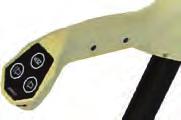
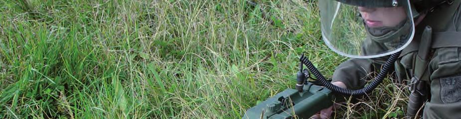
31 SCHIEBEL MIMID Schiebel Elektronische Geräte GmbH Austria GENERAL DESCRIPTION The MIMID (Miniature Mine Detector) is based on the pulse mode technology of the AN19/2 mine detector that has been the worldwide standard for minimalmetalmine detection in both military and humanitarian demining for the past ten years. It was developed to meet the specific operational requirements of the US Army Humanitarian Demining Team. It is waterproof to 30m and is suitable for use both on land and by divers for underwater operations. The detector has been in service since The lightweight, onepiece, foldable design makes it suitable for use by Special Forces or anyone likely to come into contact with mines. The folded unit can be carried on a belt, in a trouser pocket or in a rucksack, a unique feature allowing operators immediate access to the unit. The MIMID can be set up for operation in 30 seconds. Controls are within easy reach of the operator and are identical to those of the AN19/2. The length of its telescopic pole can be quickly adjusted for operation in the upright, kneeling or prone positions. WORKING METHODOLOGY The transmitting coil of the search head emits an electromagnetic pulse, which induces an eddy current in metal objects in the vicinity of the search head. These eddy currents give rise to a secondary field, which is picked up by the receiving coil. The signal from this coil is processed in the electronics unit. The operator is alerted to the presence of a metal object by a sound in the headphone and a light signal on the visual indicator. Schiebel s test piece incorporates a 0.15g steel pin (approximately the same signature as the Chinese Type 72A antipersonnel mine) that can be detected at a depth of 13cm when buried in the ground. This performance is maintained in underwater depths of some 30m. The MIMID in operation For largemagneticsignature mines/uxo, the detector gives an over edge of target indication enabling the same precise location as for smaller targets. POWER SUPPLY The MIMID is powered by four standard AAsize cells. The recommended alkaline cells provide around 7 hours operation. Similar rechargeable nickelcadmium cells provide approximately 4 hours. All recommended cells are available worldwide as are suitable automatic chargers. Rechargeable cells last for at least one year if correctly used/charged. DETECTORS IN USE TO DATE More than 1,500 MIMID detectors have been sold since They have been used by a number of armed forces, for example Israel and the U.S. FACTORY SUPPORT > All detectors are covered by a 12month, nocost warranty, and operator / maintenance training is provided, (on site or at the factory as requested), as part of the procurement package. Further training can be provided at cost. 29

32 SCHIEBEL MIMID > Spare parts, all interchangeable, are available for ten years after purchase. These can be obtained directly from the factory or from the worldwide net work of Schiebel agents. > Operator and maintenance manuals are provided in English, German, and Spanish. Schiebel technicians / factory repairs are available worldwide to provide additional support on request. MAINTENANCE AND SUPPORT The MIMID requires little maintenance due to its high reliability. Most repairs can be carried out at a workshop by Schiebeltrained technicians, using the recommended tools and test equipment (digital multimeter and oscilloscope). TEST AND EVALUATION The MIMID has been comprehensively fieldtested in all climates by the manufacturer, including underwater trials to 30m, and all detector specifications are fully proven. It has also been evaluated by Ecuador and the U.S. Test reports are available on request from the manufacturer. The detector scored well in all kinds of soil type. The results achieved in ferruginous soil were above average. Tests passed by the detector include: > International Pilot Project for Technology Cooperation, March 1999June > Gruppe Rüstung (Switzerland): Technische Erprobung von Minensuchgeräten, August Test reports were partially published and the first is available at the ITEP website: REPORTED LIMITATIONS AND STRENGTHS 1 Limitations > No transit case. > Handle does not lock down. > Elbow restraints and shaft latches are weak. Strengths > Lightweight and compact. > Weatherproof. > Preassembled. SCHIEBEL MIMID in operation 1 Y. Das, J.T. Dean, D. Lewis, J.H.J. Roosenboom, G. Zahaczewsky (eds), A multinational technical evaluation of performances of commercial off the shelf metal detectors in the context of humanitarian demining, International Pilot Project for Technology Cooperation, Final report, European Commission, Joint Research Centre, Ispra, Italy, 2001, Annex A, p

33 VALLON VMC 1 Vallon Germany GENERAL DESCRIPTION The VMC1 Metal Mine Detector has been designed for highly accurate detection of all types of metallic mines as well as plastic mines with minimal metal content, bombs, ammunition and other metallic objects in the ground or in shallow water. It is a onepiece retractable detector supplied in a soft carrying bag with a carrying belt housing the complete mine detecting set and an optional nonmagnetic prodder. Due to its small size it is easily transported and stored. Ergonomic operation and indication elements integrated in the detector housing ensure easy operation and minimum operator training. Metal alarm is by audio signal, visual bargraph and vibration alarm. Operator controls are limited to one mode selector with two soil programmes and three pushbuttons for setting sensitivity level, volume of the audio signal and compensation/ground balance. Another pushbutton integrated in the handle is used to activate the pinpoint mode. Data input allows for further upgrade of the detector s firmware. Along with its digital signal processor, the VMC1 uses an advanced pulsefield function specially improved by Vallon. It can work in mineralised soils, such as laterite, magnetite and magmatite, as well as in shallow salt and fresh water, and under the electromagnetic influence of main power lines without greatly affecting sensitivity. The VALLON VMC1 unfolded The VALLON VMC1 folded Main components of the VMC1 are 1 Oval search head with telescopic carrying bar. Detector electronics with integrated nonmagnetic loudspeaker, power supply and battery compartment. LED bargraph with 14 elements and a vibrator. Three robust pushbuttons for sensitivity control, volume control and ground compensation on the front of the housing. ON/OFF switch for two different ground conditions. Pushbutton integrated in the handle to activate the pinpoint mode. 2 Nonmagnetic test piece. 3 1 set (3 EA) round cells 1.5 V IEC R 14 Alkaline Csize, 7.8 Ah each. 4 Operation manual. 5 Field manual. 6 Field backpack for storing the complete detector with all accessories. Optional accessories (available on request) 1 Headset. 2 Hard case for storing the complete detector with all accessories. 3 Nonmagnetic prodding needle. The detector complies to environmental conditions according to MIL STD 810F, 501.4II, 502.4I, 502.4II, 503.4, 506.4III, C1. 31

34 VALLON VMC 1 Vallon Germany WORKING METHODOLOGY The search head continuously emits electromagnetic pulses as the operator sweeps close to the surface. The search head acts as both an emitter and a receiver sensing the pulsed field. If there is a metal object in the magnetic field, the following happens: > The electronics unit detects a deviation from the previous state; thus an alarm signal is produced depending on the size of the metal target. > The shape of the pulse in the VMC1 is bipolar to reduce the effect on magnetically fuzed mines. To ensure optimal use worldwide under different soil conditions, the VMC1 is provided with a programme switch to set the optimum detection features. The correct programme setting and the wide range of detection sensitivity allow detection of even plastic mines with minimum metal content in mineralized soil and also near to 50Hzpower lines or 60Hzpower lines. The detector has a builtintest procedure continuously checking reliability and proper function during operation. The pulse signal generation, signal processing, battery voltage, external connections and most important the internal operation voltages are constantly monitored. Visual and acoustic alarms are produced when a fault is found. With such reliability, the user can operate the VMC1 easily and concentrate fully on the detection tasks. DETECTORS IN USE The detectors are in service with various humanitarian aid organisations, NGOs, commercial mine clearance organisations and several armed forces. Under all circumstances the sensitivity and detection quality is not influenced by the batteryconditions. POWER SUPPLY VMC1 is powered by three round 1.5V IEC R 14 alkaline C cell batteries or rechargeable 1.2V C cells. The operational life of batteries is said to be approximately 8 hours, depending on the age, quality and the capacity of the batteries. The VALLON VMC1 the short version of the rectractable system FACTORY SUPPORT > Vallon runs a worldwide servicing network with all current spare parts in stock. Spare parts can be delivered with a corresponding maintenance manual directly to the customer for onsite repair. > Operation and maintenance training are offered at the Vallon facilities or at the customer s location. > Operation and maintenance manuals are available in English, French and German. Other languages on request. > Warranty 24 months. 32

35 MAINTENANCE SUPPORT There are no special requirements for technicians or workshop facilities. All tools needed are standard and available in most workshops. A maintenance manual is available for each detector, with stepbystep explanations. TEST AND EVALUATION The manufacturer allows access to several of its own test reports. No test report is available on the ITEP website. The VALLON VMC1 packed in a bagpack and stored in the transport pack REPORTED LIMITATIONS AND STRENGTHS Vallon says there are no limitations on the detector s use for terrain, soil or vegetation. VALLON VMH3 Vallon Germany GENERAL DESCRIPTION The onepiece VMH3 metal mine detector has been designed for highly accurate detection of all types of metallic mines as well as plastic mines with minimal metal content, bombs, ammunition and other metallic objects in the ground or in shallow water. Ease of operation and a robust mechanical design ensure reliable operation for professional ordnance clearing in battlefield operations, military training programmes and humanitarian demining. Metal alarm is by audio signal, visual bargraph and vibration alarm. Along with its digital signal processor the VMH3 uses an advanced pulsefield function specially improved by Vallon. It works in mineralized soils, such as laterite, magnetite and magmatite, as well as in shallow salt and fresh water and under the electromagnetic influence of main power lines without greatly affecting sensitivity. Data input allows for further upgrade of the detector firmware, and data output enables measured data to be evaluated using VALLON EVA2000 software, running on a laptop or personal computer. The detector can also be connected to the Vallon data loggers. Main components of the VMH3 are 1 Watertight oval search head with telescopic carrying bar (two sections) and an internally run connection cable with integrated electronics unit, nonmagnetic loudspeaker, power supply, ON/OFF switch for two different ground conditions and vibrator, armrest and battery compartment, hand grip with bargraph (14 LEDs), four robust push buttons for sensitivity control, volume control, ground compensation and pinpointing. 33
36 VALLON VMH3 Vallon Germany 2 Nonmagnetic test piece. 3 One set (3 EA) single cell batteries. 4 Operation manual. 5 Field manual 6 Field backpack for storing the detector set with all accessories. Optional accessories (available on request) 1 Headset. 2 Data recording and software. The detector complies to environmental conditions according to MIL STD 810F, 501.4II, 502.4I, 502.4II, 503.4, 506.4III, C1. WORKING METHODOLOGY The search head acts as both an emitter of electromagnetic pulses and a receiver sensing the pulsed field. If there is a metal object in the magnetic field, the following happens: > The electronics unit detects a deviation from the previous state; thus an alarm signal is produced depending on the size of the metal target. > The shape of the pulse in the VMH3 is bipolar to reduce the effect on magnetically fuzed mines. To ensure worldwide use under different soil conditions, the VMH3, has a programme switch to set the optimal detection features. The correct programme setting and the wide range of detection sensitivity allows detection of plastic mines with minimum metal content in mineralized soil, even near to 5060Hzpower lines. The detector has a builtin test procedure continuously checking the reliability and proper function of the detector. The pulse signal generation, signal processing, battery voltage, external connections and most important the internal operation voltages are constantly monitored. Visual and acoustic alarms are produced when a fault is found. With such reliability the user can operate the VMH3 easily and concentrate on detection tasks. The VALLON VMH3 ready for operation in kneeling position DETECTORS IN USE The detectors are in service with various humanitarian aid organisations, commercial mine clearance organisations and several armed forces. POWER SUPPLY VMH3 is powered by three 1.5V monocells IEC R20 (ANSI std. D) or rechargeable RSH 4 KR 35/62. The operational life of batteries is said to be as approximately 18 to 25 hours depending on the age, quality and the capacity of the batteries. 34

37 The VALLON VMH3 packed in its transportation case FACTORY SUPPORT > Vallon runs a worldwide servicing network with all current spare parts in stock. Spare parts can be delivered with a corresponding maintenance manual directly to the customer for onsite repair. > Operation and maintenance training are offered at the Vallon facilities or at the customer s location. > Operation and maintenance manuals are available in English, French and German. Other languages on request. > Warranty 24 months. MAINTENANCE SUPPORT There are no special requirements for technicians or workshop facilities. All tools needed are standard and available in most workshops. A maintenance manual is available for each detector, with stepbystep explanations. TEST AND EVALUATION The detector was tested by the EC s Joint Research Centre in Laos in 2004 and in a comparative field trail in Mozambique in 2005 as well as in a laboratory test trail by JRC, Institute for the Protection and Security of the Citizen, in Italy from November 2003 to January The following test results are available at the ITEP website: 1. Systematic Test and Evaluation of Metal Detectors. Interim Report Field Trial Mozambique, 12 April 5 May 2005; published in 2005 (see also: 2. Systematic Test and Evaluation of Metal Detectors. Interim Report Field Trial Lao, 27h September 5 November 2004; published in REPORTED LIMITATIONS AND STRENGTHS Limitations A loss of sensitivity to smaller targets. 1 Strengths During the two weeks of the training and trial, no difficulties in use or technical questions arose. The detector had no problems in completing its automatic soil compensation process in all lanes Guelle, Dieter M., Lewis, Adam M., Pike, Matthew A. and Christo Crail. Systematic Test and Evaluation of Metal Detectors (STEMD). Interim Report Field Trial Mozambique, 12 April 5 May 2005, Nov. 2005, at p. 99. Ibid, p
38 VALLON VMH3CS Vallon Germany GENERAL DESCRIPTION The VMH3CS Metal Mine Detector has been designed for the highly accurate detection of all types of metallic mines as well as plastic mines with minimal metal content, bombs, ammunition and other metallic objects in the ground or in shallow water. A 60cm search head can additionally be used to locate metalcased mines and unexploded ordnance at larger depths. Ease of operation and a robust mechanical design ensure reliable operation for professional clearing in battlefield operations, military training programmes and humanitarian demining. Metal alarm is by audio signal, visual bargraph and vibration alarm. Along with its digital signal processor the VMH3CS uses an advanced pulsefield function specially improved by Vallon. It works in mineralized soils, such as laterite, magnetite and magmatite, as well as in shallow salt and fresh water and under the electromagnetic influence of main power lines without greatly affecting sensitivity. Data input allows for further upgrades of the detector firmware, and data output enables measured data to be evaluated using Vallon EVA2000 software, running on a laptop or personal computer. The detector can also be connected to the Vallon data loggers. Main components of the VMH3CS are 1 Detector electronics with integrated armrest, nonmagnetic loudspeaker, power supply, battery compartment, ON/OFF switch for two different ground conditions and vibrator. Hand grip with visual bargraph (14 elements), four robust pushbuttons for sensitivity control, volume control, ground compensation and pinpointing. Twopiece telescopic carrying bar with plugin connection for search head. 2 Watertight oval search head with carrying bar and plugin connection to the electronics unit. 3 Nonmagnetic test piece. 4 One set (3 EA) single D cell batteries.; 5 Operation manual. 6 Field manual. 7 Field backpack for storing the detector set with all accessories. The VALLON VMH3CS ready for service from a kneeling position Optional accessories (available on request) 1 Headset. 2 Hard case for storing the complete detector set VMH3CS with all accessories. 3 UXO search head (search head with 60 cm diameter). 4 Stick probe. 5 Data recording and software. The detector complies to environmental conditions according to MIL STD 810F, 501.4II, 502.4I, 502.4II, 503.4, 506.4III, C1. WORKING METHODOLOGY The search head acts as both an emitter of electromagnetic pulses and a receiver sensing the pulsed field. If there is a metal object in the magnetic field, the following happens: > The electronics unit detects a deviation from the previous state; thus an alarm signal is produced depending on the size of the metal target. 36
39 > The shape of the pulse in the VMH3CS is bipolar to reduce the effect on magnetically fuzed mines. For use worldwide under different soil conditions, the VMH3CS can be switched to set optimal detection features. The correct programme setting and the wide range of detection sensitivity allow detection of plastic mines with minimum metal content in mineralized soil even to 50 or 60Hzpower lines. The detector has a builtintest procedure continuously checking the reliability and proper function of the detector. The pulse signal generation, signal processing, battery voltage, external connections, and most important the internal operation voltages are constantly monitored. Visual and acoustic alarms are produced when a fault is found. With such reliability, the user can operate the VMH3CS easily and concentrate fully on detection tasks. DETECTORS IN USE The detectors are in service with various humanitarian aid organisations, commercial mine clearance organisations and several armed forces. POWER SUPPLY VMH3CS is powered by three 1.5V monocells IEC R20 (ANSI std. D) or rechargeable RSH 4 KR 35/62. The operational life of batteries is said to be approximately 18 to 25 hours depending on the age, quality and capacity of the batteries. The VMH3CSlengths continuously adjustable FACTORY SUPPORT > Vallon runs a worldwide servicing network with all current spare parts in stock. Spare parts can be delivered with a corresponding maintenance manual directly to the customer for onsite repair. > Operation and maintenance training are offered either in the Vallon facilities or at the customer s location. > Operation and maintenance manuals are available in English, French, German and Spanish. Other languages on request. > Warranty 24 months. MAINTENANCE SUPPORT There are no special requirements for technicians or workshop facilities. All tools needed are standard and available in most workshops. For each detector a maintenance manual is available, with stepbystep explanations. The VALLON VMH3CS with the UXO head TEST AND EVALUATION The manufacturer allows access to several available test reports. The detector was tested by the EC s Joint Research Centre in Laos in The following test result is available at the ITEP website: 1. Systematic Test and Evaluation of Metal Detectors (STEMD). Interim Report Field Trial Lao, 27 September 5 November 2004; published in REPORTED LIMITATIONS AND STRENGTHS Vallon says there are no limitations on the detector s use for terrain, soil and vegetation. 37
40 VALLON VMM3 Vallon Germany GENERAL DESCRIPTION The Vallon VMM3 Metal Mine Detector has been designed for accurate detection of all types of metallic mines as well as plastic mines with minimal metal content, bombs, ammunition and other metallic objects in the ground or in shallow water. A 60 cm search head can be added to locate buried metalcased mines and unexploded ordnance in greater depths. Ease of operation and a robust mechanical design ensure reliable operation for professional ordnance clearing in battlefield operations military training programmes. Along with its digital signal processor the VMM3 uses an advanced pulsefield function specially improved by Vallon. It works also in mineralised soils, such as laterite, magnetite and magmatite as well as in shallow salt and fresh water and under the electromagnetic influence of main power lines without greatly affecting sensitivity. Data input allows upgrades of the detector firmware, and data output enables data to be evaluated by the Vallon EVA2000 software on a laptop. The detector can also be connected to Vallon data loggers. Main components of the VMM3 are 1 Watertight oval search head with telescopic carrying bar (three sections) with internally running connection cable and an electronics unit consisting of: > Integrated nonmagnetic loudspeaker; > Four batteries (alkaline D cells, or rechargeable); > Operating controls, all on the front panel and protected against mechanical damage or unintentional changes; > Programme selector with integrated on/off switch; COMP button for automatic fine adaptation to mineralised soil; > Data connector (with protective cap) for data input for upgrading the firmware, data output for computeraided detection and headset connection. The VALLON VMM3 with detachable electronic unit 2 Detection test piece (nonmagnetic). 3 Nonmagnetic, watertight headset; 4 Carrying belt for the electronics unit, handle, armrest and supplementary armbelt; 5 Operation and field manuals. 6 Aluminum carrying case and backpack. Optional accessories (available on request) Optional accessories are the 60cm diameter search head and a stick probe. The detector complies to environmental conditions according to MIL STD 810F, 501.4II, 502.4I, 502.4II, 503.4, 506.4III, C1. 38

41 WORKING METHODOLOGY The search head acts as both an emitter and a receiver sensing the pulsed field. If a metal object is in the magnetic field, the unit detects a deviation from the previous state producing an alarm signal, depending on the size of the metal target. The VMM3 s pulse is bipolar to reduce the effect on magnetically fuzed mines. For worldwide use under different soil conditions, VMM3 has a programme to set optimal detection features. With the correct programme setting and the wide range of detection sensitivity it can detect even plastic mines with minimum metal content in mineralised, and operate to 5060 Hz power lines. The detector has a builtin test procedure for reliability and proper functioning. The pulse signal generation, signal processing, battery voltage, external connections, and most important the internal operation voltages are constantly monitored. Visual and acoustic alarms are produced when a fault is found. The VMM3 is reliable and easy to use, allowing the operator to concentrate fully on detection tasks. DETECTORS IN USE The detectors are in service with commercial mine clearance organisations and several armed forces (including NATO members). POWER SUPPLY Four 4 x 1.5V monocell IECLR 20 (ANSI STD. D cell) or rechargeable KR35/62. Battery operational life is 30 to 40 hours depending on age, quality and the of the batteries. FACTORY SUPPORT > Vallon runs a worldwide servicing network with all current spare parts in stock. Spare parts can be delivered with a corresponding maintenance manual directly to the customer for onsite repair. > Operation and maintenance training are offered either in the Vallon facilities or at a location required by the customer. > Operation and maintenance manuals are available in English, French, German and Spanish. Other languages on request. > Warranty for 24 months. The VALLON VMM3 packed in the transport aluminium case MAINTENANCE SUPPORT There are no special requirements for technicians or workshop facilities. All tools needed are standard and available in most workshops. The maintenance manual has stepbystep explanations for repairs. TEST AND EVALUATION The manufacturer allows access to several test reports. REPORTED LIMITATIONS AND STRENGTHS The manufacturer says there are no limitations for terrain, soil and vegetation. 39

42 VALLON VMW1 Vallon Germany GENERAL DESCRIPTION The Vallon VMW1Underwater Metal Detector is a retractable detector for demining foreshores and rivers. It is supplied with a hard case housing the complete mine detecting set. Its small size and light weight facilitate underwater as well as onshore operations. The rugged search head contains the Digital Pulse Induction Sensor with integrated noise reduction features. Its shape facilitates operation in difficult and dense vegetation ashore as well as in shallow or deep water and mud. The unique design allows precise pinpointing and an excellent recognition of targets close to each other without loss of detection speed. The telescopic pole consists of three tubes. Length is easily adjusted even during operation so that detection work can be done in standing, kneeling or swimming positions. The detected metals are clearly indicated by the pluggable nonmagnetic headset and LED bargraph. Automatic continuous selfcheck and automatic detection level controls maintain sensitivity over hours of continuous operation and independently of battery level, temperature and other environmental conditions. System failures are immediately indicated by a special audio alarm. The VMW1 requires only minimal operator training. Main components of the VMW1 are 1 Complete detector with electronics unit and battery compartment, operation elements, visual indication, watertight socket for headset, integrated telescopic carrying bar with oval search head. 2 Headset. 3 Nonmagnetic test piece. 4 One set (3 EA) Round cells 1.5V IEC R 14 alkaline C cell batteries, 7.8 Ah each; 5 Safety belt. 6 Operation manual. 7 Hard case for storing the complete detector set with all accessories. The detector complies to environmental conditions according to MIL STD 810F, 501.4II, 502.4I, 502.4II, 503.4, 506.4III, C1. The Underwater Dectector VMW1 of VALLON WORKING METHODOLOGY The search head acts as both an emitter and a receiver sensing the pulsed field. If a metal object is in the magnetic field, the unit detects a deviation from the previous state producing an alarm signal, depending on the size of the metal target. The detector has a builtin test procedure for reliability and proper functioning. The pulse signal generation, signal processing, battery voltage, external connections, and most important the internal operation voltages are constantly monitored. Visual and acoustic alarms are produced when a fault is found. The bipolar pulse of the VMW1 reduces the effect on magnetically fuzed mines. The VMM1 is reliable and easy to use, allowing the operator to concentrate fully on detection tasks. 40

43 POWER SUPPLY Powered by three round cells 1.5V IEC R 14 alkaline C cell batteries or rechargeable 1.2V C cells. Operational life of the batteries is said to be approximately 9 hours depending on age, quality and capacity. DETECTORS IN USE The detectors are in service in several countries. FACTORY SUPPORT > Vallon runs a worldwide servicing network with all current spare parts in stock. Spare parts can be delivered with a corresponding maintenance manual directly to the customer for onsite repair. > Operation and maintenance training are offered either in the Vallon facilities or at a location required by the customer. > Operation and maintenance manuals are available in English, French and German. Other languages on request. > Warranty for 24 months. The VMW1 length continuously adjustable from 550mm to 1240mm MAINTENANCE SUPPORT There are no special requirements for technicians or workshop facilities. All tools needed are standard and available in most workshops. The maintenance manual has stepbystep explanations for repairs. TEST AND EVALUATION The manufacturer allows access to several test reports. REPORTED LIMITATIONS AND STRENGTHS The manufacturer says there are no limitations for terrain, soil and vegetation, and up to a water depth of 50m. The VALLON VMW1 detector packed in a small hard case 41
44 TECHNICAL SPECIFICATIONS BGIF DETECTOR 1. Brand 2. Model 3. Version 4. Used detection technology BGIF GTL Metal mine detector pulse induction DIMENSIONAL DATA 5. Working length > min. length > max. length 6. Search head > Size Search head A Search head B > Weight Search head A Search head B > Shape Search head A Search head B 7. Transport case > Weight > With equipment (full) > Dimensions > Hard Soft case (material) 8. Weight, handheld unit 9. Weight, carrying (operational detection set) 10. Weight, additional equipment 11. Weight distribution Balance 12. Other specifications 750 mm (basic) 1340 mm (with extension pole) Ø 200 mm 300 x 68 mm 0.43 kg 0.55 kg Circular Oval 4.9 kg 11 kg 645 x 330 x 175 mm Hard case aluminum 0.5 kg SYSTEM STATUS AND DEPLOYMENT 13. Status 14. Detectors Systems in use to date 15. Other types 16. Location of use In production No Worldwide ENVIRONMENTAL INFLUENCE 17. Humidity (limitations) 18. Temperature (limitations) > Storage > Operational 19. Water resistant 20. Shock Vibration resistant 21. Environmental Compensation 22. Operational hours Operating endurance > low temperature (around 0 C) > medium temperature (around 20 C) > high temperature (higher than 30 C) MIL STD 50 C to + 70 C 20 C to + 50 C, in shallow water and up to 2/3 of the first section of the search pole Automatically Up to 40h depending on battery type and capacity Up to 60h depending on battery type and capacity Up to 60h depending on battery type and capacity 42
45 DETECTION OPERATION 23. Calibration Setup > Auto Manual > Duration 24. Detection range Sensitivity details Detection performance Working depth > Lowmetalcontent mines Search head A Search head B > Antivehicle mines > Search head A Plastic AT mine Ferrous cased AT mine > Search head B Plastic AT mine Ferrous cased AT mine > ERW (please specify) 25. Output indicator 26. Pinpointing feature 27. Adjustment of search head angle 28. Soil influence 29. Best use in > Sand > Peat > Clay > Ferruginous soil (laterite) 30. Optimal sweep speed 31. Search coil Antenna Search head A Search head B 32. Limitations 33. Interference (with other detectors) POWER 34. Power supply Source 35. Operating time 36. Power supply > weight > no. of batteries size type > rechargeable > other Manual or automatic Continual Control of working depth: Sensitivity adjustment 08 cm 12 cm 12 cm 70 cm 12 cm 75 cm Depending on their size, material and the local interference Sound Can be compensated m/s Circular, ø 200 mm Oval, 300 X 68 mm No Two detectors in use should have a distance of 1m between each other Battery See item 22 8 x common AA size R6 battery, or 8 x NiMH AA size battery rechargeable (NiMH AA size battery) COSTS 37. Price > for one detector > reduction for higher quantity 38. System price > with training > spare parts > extended warranty 39. Total 40. Possibility to rent/lease OTHERS 41. Duration of warranty 42. Additional equipment 43. Additional technical data information 44. Compliant standards USD Upon request Not given Not given 24 months ISO9001
46 TECHNICAL SPECIFICATIONS CEIA DETECTOR 1. Brand 2. Model 3. Version 4. Used detection technology CEIA MILD1 3.3 Electromagnetic induction CW (Continuous Wave) DIMENSIONAL DATA 5. Working length > min. length > max. length 6. Search head > Size > Weight > Shape 7. Transport case > Weight > With equipment (full) > Dimensions > Hard Soft case (material) 8. Weight, handheld unit 9. Weight, carrying (operational detection set) 10. Weight, additional equipment 11. Weight distribution Balance 12. Other specifications SYSTEM STATUS AND DEPLOYMENT 13. Status (Development In production) 14. Detectors Systems in use to date 15. Other types Models 16. Location of use 1000 mm 1620 mm Ø 280 mm (external diameter) kg Circular 7 kg 12.5 kg 950 x 440 x 155 mm High impact polypropylene / synthetic canvas 3.2 kg 0.5 kg Well balanced Optimized for continuous operation Control of working depth Knob sensitivity adjustment In production 9000 No Afghanistan, Egypt, Finland, Sweden, Lebanon Ethiopia, Thailand, etc ENVIRONMENTAL INFLUENCE 17. Humidity (limitations) 18. Temperature (limitations) > Storage > Operational 19. Water resistant ( / No) 20. Shock Vibration resistant 21. Environmental Compensation 22. Operational hours Operating endurance > low temperature (around 0 C) > medium temperature (around 20 C) > high temperature (higher than 30 C) No influence 55 C to +75 C 46 C to +65 C IP68 (IEC 529) exceeding MIL STD 810 E Automatically MTBF = according to MILHDBK 217 MTBF = according to MILHDBK 217 At 35 C MTBF = according to MIL HDBK
47 DETECTION OPERATION 23. Calibration Setup > Auto Manual > Duration 24. Detection range Sensitivity details Detection performance Working depth > Small metal content mines (type of mine) > Antitank mines (type of mine) > ERW (please specify) 25. Output indicator 26. Pinpointing feature 27. Adjustment of search head angle 28. Soil influence 29. Best use in > Sand > Peat > Clay > Ferruginous soil (laterite) 30. Optimal sweep speed 31. Search coil Antenna 32. Limitations 33. Interference (with other detectors) Automatic No limit Optimized according to the mines and soils Optimized according to the mines and soils Optimized according to the mines and soils Sound Dual tone 0 up to 97 From 0cm/s to the maximum human operator sweep Circular POWER 34. Power supply Source 35. Operating time 36. Power supply > weight > no. of batteries size type > rechargeable > other 4x1.5 V alkaline batteries or 4x1.2 V NIMH rechargeable batteries > 65 hours with alkaline batteries; > 35 hours with rechargeables batteries Total for 4 batteries = kg (alkaline batteries) = 0.61 kg (rechargeables batteries) 4 ANSI Std D IEC Std LR20, alkaline or rechargeable COSTS 37. Price > for one detector on request > reduction for higher quantity 38. System price > with training > spare parts > extended warranty 39. Total 40. Possibility to rent/lease OTHERS 41. Duration of warranty 42. Additional equipment 43. Additional technical data information 44. Compliant standards Battery charger MILD1/BC On request MILSTD 810 E and others on requests 45
48 TECHNICAL SPECIFICATIONS EBINGER DETECTOR 1. Brand 2. Model 3. Version 4. Used detection technology EBINGER EBEX 420 H Metal detector sine wave DIMENSIONAL DATA 5. Working length > min. length > max. length 6. Search head > Size > Weight > Shape 7. Transport case > Weight > With equipment (full) > Dimensions > Hard Soft case (material) 8. Weight, handheld unit 9. Weight, carrying (operational detection set) 10. Weight, additional equipment 11. Weight distribution Balance 12. Other specifications 670 mm (short version) 1,840 mm (long version) Ø 200 mm 0.5 kg Circular 2 kg 5 kg Hard plastic canvas satchel 0.88 kg (short) 1.45 kg (long) 0.88 kg (short) 1.45 kg (long) Modular systems without any cables SYSTEM STATUS AND DEPLOYMENT 13. Status (Development In production) 14. Detectors Systems in use to date 15. Other types Models 16. Location of use In production Approx. 2,000 Worldwide ENVIRONMENTAL INFLUENCE 17. Humidity (limitations) 18. Temperature (limitations) > Storage > Operational 19. Water resistant ( / No) 20. Shock Vibration resistant 21. Environmental Compensation 22. Operational hours Operating endurance > low temperature (around 0 C) > medium temperature (around 20 C) > high temperature (higher than 30 C) 0 95% 53 C to +70 C 30 C to +55 C up to 1.3m Manual Up to 75h, depends on solar radiation Up to 75h, depends on solar radiation Up to 75h, depends on solar radiation 46
49 DETECTION OPERATION 23. Calibration Setup > Auto Manual > Duration 24. Detection range Sensitivity details Detection performance Working depth > Control of working depth > Lowmetalcontent mines > Antitank mines (type of mine) > ERW (please specify) 25. Output indicator 26. Pinpointing feature 27. Adjustment of search head angle 28. Soil influence 29. Best use in > Sand > Peat > Clay > Ferruginous soil (laterite) 30. Optimal sweep speed 31. Search coil Antenna 32. Limitations 33. Interference (with other detectors) Manual Continual Sensitivity adjustment manual Depending on their size, material and the local interference Depending on their size, material and the local interference Depending on their size, material and the local interference Sound No m per second Ø 200mm circular No < Safety distance POWER 34. Power supply Source 35. Operating time 36. Power supply > weight > no. of batteries size type > rechargeable > other Battery See point 23 1 x 9V dry battery LR61 1 x 9V rechargeable LR61 Power supply from solar panel COSTS 37. Price > for one detector on request > reduction for higher quantity 38. System price > with training > spare parts > extended warranty 39. Total 40. Possibility to rent/lease OTHERS 41. Duration of warranty 42. Additional equipment 43. Additional technical data information 44. Compliant standards US$1,000 US$2,000 On request On request On request On request 24 months Extension rod MILSTD 461, MILSTD 810, DIN EN IS0 900:
50 TECHNICAL SPECIFICATIONS EBINGER DETECTOR 1. Brand 2. Model 3. Version 4. Used detection technology EBINGER EBEX PBD (stands for Pulse Bipolar Dynamic) Metal detector pulse induction DIMENSIONAL DATA 5. Working length > min. length > max. length 6. Search head > Size > Weight > Shape 7. Transport case > Weight > With equipment (full) > Dimensions > Hard Soft case (material) 8. Weight, handheld unit 9. Weight, carrying (operational detection set) 10. Weight, additional equipment 11. Weight distribution Balance 12. Other specifications 1,080 mm (short version) 1,650 mm (long version) Ø 260 x 156 mm 0.5 kg Oval 2 kg 8.5 kg Hard plastic canvas satchel 2.2 kg (short) 2.4 kg (long) 2.2 kg (short) 2.4 kg (long) Modular systems without any cables SYSTEM STATUS AND DEPLOYMENT 13. Status (Development In production) 14. Detectors Systems in use to date 15. Other types Models 16. Location of use In production Approx. 5,000 Worldwide ENVIRONMENTAL INFLUENCE 17. Humidity (limitations) 18. Temperature (limitations) > Storage > Operational 19. Water resistant ( / No) 20. Shock Vibration resistant 21. Environmental Compensation 22. Operational hours Operating endurance > low temperature (around 0 C) > medium temperature (around 20 C) > high temperature (higher than 30 C) 0 95% 53 C to +70 C 30 C to +55 C up to 1.3m Auto Manual Up to 50h, depends on type of battery Up to 50h, depends on type of battery Up to 50h, depends on type of battery 48
51 DETECTION OPERATION 23. Calibration Setup > Auto Manual > Duration 24. Detection range Sensitivity details Detection performance Working depth > Control of working depth > Lowmetalcontent mines > Antitank mines (type of mine) > ERW (please specify) 25. Output indicator 26. Pinpointing feature 27. Adjustment of search head angle 28. Soil influence 29. Best use in > Sand > Peat > Clay > Ferruginous soil (laterite) 30. Optimal sweep speed 31. Search coil Antenna 32. Limitations 33. Interference (with other detectors) Manual or Automatic Continual Sensitivity adjustment manual Depending on their size, material and the local interference Depending on their size, material and the local interference Depending on their size, material and the local interference Sound Under certain circumstances m per second Ø 260 x 156 mm oval No < Safety distance POWER 34. Power supply Source 35. Operating time 36. Power supply > weight > no. of batteries size type > rechargeable > other Battery See point 23 6 x 1.5V dry batteries Ccell 6 x 1.2V rechargeable batteries 1 x 12V battery pack COSTS 37. Price > for one detector on request > reduction for higher quantity 38. System price > with training > spare parts > extended warranty 39. Total 40. Possibility to rent/lease US$2,000 US$3,000 On request On request On request On request OTHERS 41. Duration of warranty 42. Additional equipment 43. Additional technical data information 44. Compliant standards 24 months UXO head 45 cm, cylinder probe MILSTD 461,MILSTD 810, DIN EN IS0 9001:
52 TECHNICAL SPECIFICATIONS EBINGER DETECTOR 1. Brand 2. Model 3. Version 4. Used detection technology EBINGER EBEX 421 GC (stands for Ground Compensation) Metal detector pulse induction DIMENSIONAL DATA 5. Working length > min. length > max. length 6. Search head > Size > Weight > Shape 7. Transport case > Weight > With equipment (full) > Dimensions > Hard Soft case (material) 8. Weight, handheld unit 9. Weight, carrying (operational detection set) 10. Weight, additional equipment 11. Weight distribution Balance 12. Other specifications 1,000 mm (short version) 1,700 mm (long version) Ø 230 mm (300 x 170 mm) 0.5 kg Circular, oval 2 kg kg Hard plastic canvas satchel 2.2 kg (short) 2.4 kg (long) 2.2 kg (short) 2.4 kg (long) Modular systems without any cables SYSTEM STATUS AND DEPLOYMENT 13. Status (Development In production) 14. Detectors Systems in use to date 15. Other types Models 16. Location of use In production Approx. 2,000 Worldwide ENVIRONMENTAL INFLUENCE 17. Humidity (limitations) 18. Temperature (limitations) > Storage > Operational 19. Water resistant ( / No) 20. Shock Vibration resistant 21. Environmental Compensation 22. Operational hours Operating endurance > low temperature (around 0 C) > medium temperature (around 20 C) > high temperature (higher than 30 C) 0 95% 53 C to +70 C 30 C to +55 C up to 1.3m Auto Manual Up to 75h, GC mode up to 25h, depends on type of battery Up to 75h, GC mode up to 25h, depends on type of battery Up to 75h, GC mode up to 25h, depends on type of battery 50h 50
53 DETECTION OPERATION 23. Calibration Setup > Auto Manual > Duration 24. Detection range Sensitivity details Detection performance Working depth > Control of working depth > Lowmetalcontent mines > Antitank mines (type of mine) > ERW (please specify) 25. Output indicator 26. Pinpointing feature 27. Adjustment of search head angle 28. Soil influence 29. Best use in > Sand > Peat > Clay > Ferruginous soil (laterite) 30. Optimal sweep speed 31. Search coil Antenna 32. Limitations 33. Interference (with other detectors) Manual or Automatic Continual Sensitivity adjustment manual Depending on their size, material and the local interference Depending on their size, material and the local interference Depending on their size, material and the local interference Sound Specially developed for laterite soil m per second Ø 230 mm circular, (300 x 170 mm oval) No < Safety distance POWER 34. Power supply Source 35. Operating time 36. Power supply > weight > no. of batteries size type > rechargeable > other Battery See point 23 8 x 1.5V dry batteries Ccell 8 x 1.2V rechargeable batteries 1 x 12V battery pack COSTS 37. Price > for one detector on request > reduction for higher quantity 38. System price > with training > spare parts > extended warranty 39. Total 40. Possibility to rent/lease OTHERS 41. Duration of warranty 42. Additional equipment 43. Additional technical data information 44. Compliant standards US$2,000 US$3,000 On request On request On request On request 24 months UXO head 45 cm MILSTD 461,MILSTD 810, DIN EN IS0 9001:
54 TECHNICAL SPECIFICATIONS FOERSTER DETECTOR 1. Brand 2. Model 3. Version 4. Used detection technology FOERSTER MINEX 2FD Continuous wave emi with two parallel frequencies in combination with gradiometric receiving coil system DIMENSIONAL DATA 5. Working length > min. length > max. length 6. Search head > Size > Weight > Shape 7. Transport case > Weight > With equipment (full) > Dimensions > Hard Soft case (material) 8. Weight, handheld unit 9. Weight, carrying (operational detection set) 10. Weight, additional equipment 11. Weight distribution Balance 12. Other specifications 930 mm 1,660 mm 210 x 285 mm N/A due to onepiece design Oval 5.7 kg Approx. 8 kg 97 x 24 s 37 cm Plastic hardcase backpack optional 2.2 kg 2.6 kg incl batteries Backpack 0.8 kg headphone 0.1 kg Balanced around the handgrip SYSTEM STATUS AND DEPLOYMENT 13. Status (Development In production) 14. Detectors Systems in use to date 15. Other types Models 16. Location of use In production Previous versions MINEX 2FD and Humanitarian and military demining forces in more than 30 countries worldwide. ENVIRONMENTAL INFLUENCE 17. Humidity (limitations) 18. Temperature (limitations) > Storage > Operational 19. Water resistant ( / No) 20. Shock Vibration resistant 21. Environmental Compensation 22. Operational hours Operating endurance > low temperature (around 0 C) > medium temperature (around 20 C) > high temperature (higher than 30 C) No limitations 57 C to +71 C (135 F to +160 F) 37 C to +71 C (99 F to +160 F) Search head waterproof, control unit splash water proof acc. MIL STD 810E Acc. MIL STD 810E Automatic very agressive soil compensated by automatic learning sequence Depending of working sequence up to 25 h Depending of working sequence up to 30 to 50 h Depending of working sequence up to 30 to 50 h DETECTION OPERATION 23. Calibration Setup > Auto Manual > Duration Manual or Automatic Continual 52
55 24. Detection range Sensitivity details Detection performance Working depth > Small metal content mines (type of mine) > Antitank mines (type of mine) > ERW (please specify) 25. Output indicator 26. Pinpointing feature 27. Adjustment of search head angle 28. Soil influence 29. Best use in > Sand > Peat > Clay > Ferruginous soil (laterite) 30. Optimal sweep speed 31. Search coil Antenna 32. Limitations 33. Interference (with other detectors) Type 72 A approx. 18 cm TM 62M up to 60 cm See AT mine for exemplary comparison on bigger objects. For ERW search Foerster offers highly specialized magnetometers Audio by inbuilt speaker or headphones Two sounds, switching when passing an object with the center of the searchhead Manual Up to a certain defree automatic adaption, agressive soil can be learned by operating a pushbutton Signal quality not speed dependent, no particular limit Gradiometric coil system (1 sending 2 receiving coils) Printed multilayer construction Not usable by divers Approx. 5 mtr POWER 34. Power supply Source 35. Operating time 36. Power supply > weight > no. of batteries size type > rechargeable > other 3 x 1.5V monocell IECLR 20 (ANSI Std. size D) hrs with alkaline batteries 3 x 1.5V monocell IECLR 20 (ANSI Std. size D), possible COSTS 37. Price > for one detector on request > reduction for higher quantity 38. System price > with training > spare parts > extended warranty 39. Total 40. Possibility to rent/lease US$2,000 US$3,000 Depending on quantity Depending on quantity Available on request T.B.D. Available OTHERS 41. Duration of warranty 42. Additional equipment 43. Additional technical data information 44. Compliant standards 24 months Headphones, backpack, workshop equipment & tools Service manuals, training program MILSTD 810E Random vibration MILSTD 810E Procedure I Mechanical Shock MILSTD 810E Procedure IV Drop Test MILSTD 810E High Temperatures MILSTD 810E Low Temperatures MILSTD 810E Blowing Rain MILSTD 810E Temperature Shock MILSTD 810E Leakage Test MILSTD 810E Procedure I Solar Radiation (Sunshine) Mission MTBF = h(in accordance to MILSTD217F) EMC according to EN 55022:1998(ClassB) and EN :1996+A1:
56 TECHNICAL SPECIFICATIONS MINELAB DETECTOR 1. Brand 2. Model 3. Version 4. Used detection technology MINELAB F1A4 8 Pulse induction multiperiodsensing DIMENSIONAL DATA 5. Working length > min. length > max. length 6. Search head > Size > Weight > Shape 7. Transport case > Weight > With equipment (full) > Dimensions > Hard Soft case (material) 8. Weight, handheld unit 9. Weight, carrying (operational detection set) 10. Weight, additional equipment 11. Weight distribution Balance 12. Other specifications 1,200 mm 1,450 mm Ø 200 mm Circular with protective skid plate 4 kg 8 kg 320 mm x 840 mm x 180 mm Impact plastic/cordura 1.5 kg (control box detached) 3.1 kg Adjustable Internal speaker and external earset SYSTEM STATUS AND DEPLOYMENT 13. Status (Development In production) 14. Detectors Systems in use to date 15. Other types Models 16. Location of use In production 10,000 plus F1A4 UXO version 50+ countries ENVIRONMENTAL INFLUENCE 17. Humidity (limitations) 18. Temperature (limitations) > Storage > Operational 19. Water resistant ( / No) 20. Shock Vibration resistant 21. Environmental Compensation 22. Operational hours Operating endurance > low temperature (around 0 C) > medium temperature (around 20 C) > high temperature (higher than 30 C) Nil 55 C to +75 C 30 C to +60 C (control box IP 65) Auto 54
57 DETECTION OPERATION 23. Calibration Setup > Auto Manual > Duration 24. Detection range Sensitivity details Detection performance Working depth > Small metal content mines (type of mine) > Antitank mines (type of mine) > ERW (please specify) 25. Output indicator 26. Pinpointing feature 27. Adjustment of search head angle 28. Soil influence 29. Best use in > Sand > Peat > Clay > Ferruginous soil (laterite) 30. Optimal sweep speed 31. Search coil Antenna 32. Limitations 33. Interference (with other detectors) Auto 2 min assembly 10 sec. switch and go Type 72 at 1519 cm Metal mine at 1.0 m 500 lb bomb at 1.8 m Audio Edge detection Automatic rejection and compensation 0.6 m per second enclosed circular 2 m POWER 34. Power supply Source 35. Operating time 36. Power supply > weight > no. of batteries size type > rechargeable > other 4 x D cell alkaline or rechargeable Alkaline 24 hrs rechargeable 12 hrs 800 gm 4 x D cell 1.5V LR20 4 x D cell 4.5 Ahnicad COSTS 37. Price > for one detector on request > reduction for higher quantity 38. System price > with training > spare parts > extended warranty 39. Total 40. Possibility to rent/lease US$1,000 US$2,000 Subject to location and quantity purchased On minelab recommendation Subject to quantity purchased On request OTHERS 41. Duration of warranty 42. Additional equipment 43. Additional technical data information 44. Compliant standards 15 months (extendable on request) F Series battery charger On request Designed to MIL STD 810 F 55
58 TECHNICAL SPECIFICATIONS MINELAB DETECTOR 1. Brand 2. Model 3. Version 4. Used detection technology MINELAB F3 1 Pulse induction multiperiodsensing DIMENSIONAL DATA 5. Working length > min. length > max. length 6. Search head > Size > Weight > Shape 7. Transport case > Weight > With equipment (full) > Dimensions > Hard Soft case (material) 8. Weight, handheld unit 9. Weight, carrying (operational detection set) 10. Weight, additional equipment 11. Weight distribution Balance 12. Other specifications 760 mm 1,500 mm Ø 200 mm Circular with protective skid plate 6.5 kg 10.5 kg 1,600 mm x 1,200 mm x 180 mm Impact plastic/cordura 2.3 kg (battery pack detached) 3.2 kg Adjustable Internal speaker and external earset sensitivity end caps SYSTEM STATUS AND DEPLOYMENT 13. Status (Development In production) 14. Detectors Systems in use to date 15. Other types Models 16. Location of use In production 3,000 plus 25+ countries ENVIRONMENTAL INFLUENCE 17. Humidity (limitations) 18. Temperature (limitations) > Storage > Operational 19. Water resistant ( / No) 20. Shock Vibration resistant 21. Environmental Compensation 22. Operational hours Operating endurance > low temperature (around 0 C) > medium temperature (around 20 C) > high temperature (higher than 30 C) Nil 55 C to +75 C 30 C to +60 C IP 65 Auto 56
59 DETECTION OPERATION 23. Calibration Setup > Auto Manual > Duration 24. Detection range Sensitivity details Detection performance Working depth > Small metal content mines (type of mine) > Antitank mines (type of mine) > ERW (please specify) 25. Output indicator 26. Pinpointing feature 27. Adjustment of search head angle 28. Soil influence 29. Best use in > Sand > Peat > Clay > Ferruginous soil (laterite) 30. Optimal sweep speed 31. Search coil Antenna 32. Limitations 33. Interference (with other detectors) Auto 10 sec. switch and go Type 72 at 1519 cm Metal mine at 1.0 m 500 lb bomb > 1.0 m Audio and optional led display Edge detection Automatic rejection and compensation 0.6 m per second enclosed circular 2 m POWER 34. Power supply Source 35. Operating time 36. Power supply > weight > no. of batteries size type > rechargeable > other 4 x D cell alkaline or rechargeable Alkaline 27 hrs rechargeable 15 hrs 800 gm 4 x D cell 1.5V LR20 4 x D cell 4.5 Ahnicad COSTS 37. Price > for one detector on request > reduction for higher quantity 38. System price > with training > spare parts > extended warranty 39. Total 40. Possibility to rent/lease US$2,000 US$3,000 Subject to location and quantity purchased On minelab recommendation Subject to quantity purchased On request OTHERS 41. Duration of warranty 42. Additional equipment 43. Additional technical data information 44. Compliant standards 15 months (extendable on request) F Series battery charger On request Designed to MIL STD 810 F 57
60 TECHNICAL SPECIFICATIONS SCHIEBEL DETECTOR 1. Brand 2. Model 3. Version 4. Used detection technology SCHIEBEL AN19/2 Mine Detecting Set Mod 7 Electromagnetic pulse induction DIMENSIONAL DATA 5. Working length > min. length > max. length 6. Search head > Size > Weight > Shape 7. Transport case > Weight > With equipment (full) > Dimensions > Hard Soft case (material) 8. Weight, handheld unit 9. Weight, carrying (operational detection set) 10. Weight, additional equipment 11. Weight distribution Balance 12. Other specifications 1,400 mm 1,600 mm Ø 267 mm 0.6 kg Round 2.2 kg 6.02 kg 802 mm x 315 mm x 125 mm Metal Search head with telescopic pole 1.22 kg 2.41 kg + set of batteries 0.58 kg Electronic unit is shoulderstrap mounted, headphone on head, and handheld item is balanced by the armrest SYSTEM STATUS AND DEPLOYMENT 13. Status (Development In production) 14. Detectors Systems in use to date 15. Other types Models 16. Location of use In production 40,000 plus Worldwide ENVIRONMENTAL INFLUENCE 17. Humidity (limitations) 18. Temperature (limitations) > Storage > Operational 19. Water resistant ( / No) 20. Shock Vibration resistant 21. Environmental Compensation 22. Operational hours Operating endurance > low temperature (around 0 C) > medium temperature (around 20 C) > high temperature (higher than 30 C) No 55 C to +85 C (67 F to +185 F) 40 C to +70 C (40 F to +158 F) Auto Approx. 65 h Approx. 70 h 75 h or more 58
61 DETECTION OPERATION 23. Calibration Setup > Auto Manual > Duration 24. Detection range Sensitivity details Detection performance Working depth > Small metal content mines (type of mine) > Antitank mines (type of mine) > ERW (please specify) 25. Output indicator 26. Pinpointing feature 27. Adjustment of search head angle 28. Soil influence 29. Best use in > Sand > Peat > Clay > Ferruginous soil (laterite) 30. Optimal sweep speed 31. Search coil Antenna 32. Limitations 33. Interference (with other detectors) Calibration not required. Manual setup using single controlfor sensitivity. Sound may also be adjusted to suit local Less than 30 s 72A 18 cm M14 14 cm Metal antivehicle at 1m; plastic antivehicle: nearly all types at operational threat depth 500 lb bomb at 1.8m Sound and optional visualled display by edge of target warbling tone Easily adjusted by angel wingnut to cover all necessary operational situations (more than 180 degrees) Can operate in light magnetic soil with reduced but normally acceptable performance No Static to 2 m/s Medium and heavy (strong) magnetic soil None at distance above 2m separation POWER 34. Power supply Source 35. Operating time 36. Power supply > weight > no. of batteries size type > rechargeable > other Standard D size alkaline cells Approx. 70h 580 gm 4 x 1.5V R20 ANSI size D Rechargeable NiCad cells can be used but operating time is reduced to 38h COSTS 37. Price > for one detector on request > reduction for higher quantity 38. System price > with training > spare parts > extended warranty 39. Total 40. Possibility to rent/lease US$2,000 US$3,000 OTHERS 41. Duration of warranty 42. Additional equipment 43. Additional technical data information 44. Compliant standards 12 months (extendable on request) ISO9001, AQA P4 59
62 TECHNICAL SPECIFICATIONS SCHIEBEL DETECTOR 1. Brand 2. Model 3. Version 4. Used detection technology SCHIEBEL ATMID TM All Terrain Mine Detector Electromagnetic pulse induction and continuous wave induction DIMENSIONAL DATA 5. Working length > min. length > max. length 6. Search head > Size > Weight > Shape 7. Transport case > Weight > With equipment (full) > Dimensions > Hard Soft case (material) 8. Weight, handheld unit 9. Weight, carrying (operational detection set) 10. Weight, additional equipment 11. Weight distribution Balance 12. Other specifications 1,400 mm 1,600 mm Ø 267 mm 0.82 kg Round 2.2 kg 6.36 kg 802 mm x 315 mm x 125 mm Metal 1.61 kg 3.27 kg including set of batteries Headphone 0.17 kg Electronic unit is shoulderstrap mounted, headphone on head, and handheld item is balanced by the armrest SYSTEM STATUS AND DEPLOYMENT 13. Status (Development In production) 14. Detectors Systems in use to date 15. Other types Models 16. Location of use In production 900 plus AN19/2 VARIOUS, MIMID Worldwide ENVIRONMENTAL INFLUENCE 17. Humidity (limitations) 18. Temperature (limitations) > Storage > Operational 19. Water resistant ( / No) 20. Shock Vibration resistant 21. Environmental Compensation 22. Operational hours Operating endurance > low temperature (around 0 C) > medium temperature (around 20 C) > high temperature (higher than 30 C) No 55 C to +85 C 40 C to +70 C Auto Approx. 65 h Approx. 70 h Approx. 75 h 60
63 DETECTION OPERATION 23. Calibration Setup > Auto Manual > Duration 24. Detection range Sensitivity details Detection performance Working depth > Small metal content mines (type of mine) > Antitank mines (type of mine) > ERW (please specify) 25. Output indicator 26. Pinpointing feature 27. Adjustment of search head angle 28. Soil influence 29. Best use in > Sand > Peat > Clay > Ferruginous soil (laterite) 30. Optimal sweep speed 31. Search coil Antenna 32. Limitations 33. Interference (with other detectors) Automatic ground balance; manually initiated and sensitivity then manually adjusted by a single control Approx. 30 s 72A 20 cm M14 14 cm Metal antivehicle at 1m; plastic antivehicle: nearly all types at operational threat depth NATO standard 7.62 rounds, at 40+cm, larger items down to 1 m in depth Audio tone Easily adjusted by angel wingnut to cover all necessary operational situations (more than 180 degrees) Automatically balanced out metres per second Proximity to high power rf/radar transmitters Mutual interference possible up to 8 m in CW POWER 34. Power supply Source 35. Operating time 36. Power supply > weight > no. of batteries size type > rechargeable > other Battery DC voltage Approx. 70h 580 gm 4 x 1.5V R20 ANSI size D Ni/Cad 1.5V COSTS 37. Price > for one detector on request > reduction for higher quantity 38. System price > with training > spare parts > extended warranty 39. Total 40. Possibility to rent/lease US$2,000 US$3,000 OTHERS 41. Duration of warranty 42. Additional equipment 43. Additional technical data information 44. Compliant standards 12 months ISO9001, AQA P4 61
64 TECHNICAL SPECIFICATIONS SCHIEBEL DETECTOR 1. Brand 2. Model 3. Version 4. Used detection technology SCHIEBEL MIMID Miniature Mine Detector Electromagnetic pulse induction DIMENSIONAL DATA 5. Working length > min. length > max. length 6. Search head > Size > Weight > Shape 7. Transport case > Weight > With equipment (full) > Dimensions > Hard Soft case (material) 8. Weight, handheld unit 9. Weight, carrying (operational detection set) 10. Weight, additional equipment 11. Weight distribution Balance 12. Other specifications 656 mm 1,262 mm 328 mm Integrated in mine detector Rectangular 0.64 kg 2 kg 328 mm x 102 mm x 56 mm Soft 1.36 kg 1.36 kg + set of batteries 0.1 kg Mine prodder Various. All of the weight is handheld but the unit is counterbalanced at the handle by the entire armrest SYSTEM STATUS AND DEPLOYMENT 13. Status (Development In production) 14. Detectors Systems in use to date 15. Other types Models 16. Location of use In production 1,500 plus Worldwide ENVIRONMENTAL INFLUENCE 17. Humidity (limitations) 18. Temperature (limitations) > Storage > Operational 19. Water resistant ( / No) 20. Shock Vibration resistant 21. Environmental Compensation 22. Operational hours Operating endurance > low temperature (around 0 C) > medium temperature (around 20 C) > high temperature (higher than 30 C) No 55 C to +85 C 40 C to +70 C Waterproof to 30m Auto Approx. 6.5 h Approx. 7 h Approx. 7.5 h 62
65 DETECTION OPERATION 23. Calibration Setup > Auto Manual > Duration 24. Detection range Sensitivity details Detection performance Working depth > Small metal content mines (type of mine) > Antitank mines (type of mine) > ERW (please specify) 25. Output indicator 26. Pinpointing feature 27. Adjustment of search head angle 28. Soil influence 29. Best use in > Sand > Peat > Clay > Ferruginous soil (laterite) 30. Optimal sweep speed 31. Search coil Antenna 32. Limitations 33. Interference (with other detectors) Calibration not required. Manual setup using single control for sensitivity. Sound may also be adjusted to suit local conditions Less than 30s Type 72 A 14 cm; M14 12 cm Metallic mines down to 80cm plastic mines at threat depth NATO standard 7.62 round 32cm. Larger items down to 80cm Audio tone and visual LED display Easily adjusted to cover all necessary operational situations (more than 180 degrees) Light laterite with reduced sensitivity 0.2 metres per second Search coil None above 2 m separation POWER 34. Power supply Source 35. Operating time 36. Power supply > weight > no. of batteries size type > rechargeable > other Battery DC voltage Approx. 7 h 0.1 kg 4 x 1.5V LR6 ANSI size AA, but operating time is reduced to 4h COSTS 37. Price > for one detector on request > reduction for higher quantity 38. System price > with training > spare parts > extended warranty 39. Total 40. Possibility to rent/lease US$3,000 US$4,000 OTHERS 41. Duration of warranty 42. Additional equipment 43. Additional technical data information 44. Compliant standards 12 months Titanium mine prodder, test piece. Carry bag available in green, camouflage or black ISO9001, AQA P4 63
66 TECHNICAL SPECIFICATIONS VALLON DETECTOR 1. Brand 2. Model 3. Version 4. Used detection technology VALLON VMC1 Metal detector Pulse induction DIMENSIONAL DATA 5. Working length > min. length > max. length 6. Search head > Size > Weight > Shape 7. Transport case > Weight > With equipment (full) > Dimensions > Hard Soft case (material) 8. Weight, handheld unit 9. Weight, carrying (operational detection set) 10. Weight, additional equipment 11. Weight distribution Balance 12. Other specifications 300 mm (from grip to search head) 1,240 mm (long version) 138 x 325 mm Oval Hard case: approx. 2 kg (optional accessory) Field backpack: approx. 0.3 kg (standard accessory) Hard case with equipment (full): approx. 5 kg (optional accessory) Field backpack: approx. 3.1 kg (standard accessory) Hard case (optional accessory): 410 x 325 x 165 mm Field backpack (standard accessory): 370 x 250 x 120 mm Hard case / Plastic Field backpack / Textile 2.3 kg Approx. 2.3 kg Head set 110 g SYSTEM STATUS AND DEPLOYMENT 13. Status (Development In production) 14. Detectors Systems in use to date 15. Other types Models 16. Location of use In production Not given VMH3CS VMM3 VMH3 Worldwide ENVIRONMENTAL INFLUENCE 17. Humidity (limitations) 18. Temperature (limitations) > Storage > Operational 19. Water resistant ( / No) 20. Shock Vibration resistant 21. Environmental Compensation 22. Operational hours Operating endurance According to MIL STD 810F 57 C to +71 C 32 C to +55 C up to 1,5 m Auto Up to 8 hours depending on battery type and capacity 64
67 DETECTION OPERATION 23. Calibration Setup > Auto Manual > Duration 24. Detection range Sensitivity details Detection performance Working depth > Small metal content mines (type of mine) > Antitank mines (type of mine) > ERW (please specify) 25. Output indicator 26. Pinpointing feature 27. Adjustment of search head angle 28. Soil influence 29. Best use in > Sand > Peat > Clay > Ferruginous soil (laterite) 30. Optimal sweep speed 31. Search coil Antenna 32. Limitations 33. Interference (with other detectors) Auto A few seconds Depending on their size, material and the local interference Depending on their size, material and the local interference Depending on their size, material and the local interference Sound, visual bargraph, vibration With a joint 0,2 1,5 m/sec, pinpoint mode: 00.2 m/sec Oval shape with 138 x 325 mm No 2 detectors should have a distance of 2 meter to each other POWER 34. Power supply Source 35. Operating time 36. Power supply > weight > no. of batteries size type > rechargeable > other Battery See point 22 3 ea. 1,5 V standard batteries Csize 3 ea. 1,2 V rechargeable battery Csize COSTS 37. Price > for one detector on request > reduction for higher quantity 38. System price > with training > spare parts > extended warranty 39. Total 40. Possibility to rent/lease Upon request Upon request worldwide Upon request Upon request Upon request OTHERS 41. Duration of warranty 42. Additional equipment 43. Additional technical data information 44. Compliant standards 24 months Headset, hard case, nonmagnetic prodder, data recording DIN EN ISO 9001:2000 MIL STD 810F, 501.4II, 502.4I, 502.4II, 503.4, 506.4III, C1 65
68 TECHNICAL SPECIFICATIONS VALLON DETECTOR 1. Brand 2. Model 3. Version 4. Used detection technology VALLON VMH3 Metal detector Pulse induction DIMENSIONAL DATA 5. Working length > min. length > max. length 6. Search head > Size > Weight > Shape 7. Transport case > Weight > With equipment (full) > Dimensions > Hard Soft case (material) 8. Weight, handheld unit 9. Weight, carrying (operational detection set) 10. Weight, additional equipment 11. Weight distribution Balance 12. Other specifications 793 mm (short version, 100 mm from grip to search head) 1,386 mm (long version) 170 x 308 mm 0.63 kg Oval Approx. 1 kg Approx. 4.8 kg 845 x 260 x 325 mm Soft case (textile) 2.5 kg (with oval search head) 2.5 kg Head set 110 g SYSTEM STATUS AND DEPLOYMENT 13. Status (Development In production) 14. Detectors Systems in use to date 15. Other types Models 16. Location of use In production Not given VMH3CS VMC1 VMM3 Worldwide ENVIRONMENTAL INFLUENCE 17. Humidity (limitations) 18. Temperature (limitations) > Storage > Operational 19. Water resistant ( / No) 20. Shock Vibration resistant 21. Environmental Compensation 22. Operational hours Operating endurance > low temperature (around 0 C) > medium temperature (around 20 C) > high temperature (higher than 30 C) According to MIL STD 810F 57 C to +71 C 32 C to +55 C up to 1,5 m Auto Up to 20 hours depending on battery type and capacity Up to 25 hours depending on battery type and capacity Up to 25 hours depending on battery type and capacity 66
69 DETECTION OPERATION 23. Calibration Setup > Auto Manual > Duration 24. Detection range Sensitivity details Detection performance Working depth > Small metal content mines (type of mine) > Antitank mines (type of mine) > ERW (please specify) 25. Output indicator 26. Pinpointing feature 27. Adjustment of search head angle 28. Soil influence 29. Best use in > Sand > Peat > Clay > Ferruginous soil (laterite) 30. Optimal sweep speed 31. Search coil Antenna 32. Limitations 33. Interference (with other detectors) Auto A few seconds Depending on their size, material and the local interference Depending on their size, material and the local interference Depending on their size, material and the local interference Sound, visual bargraph, vibration With a joint Adjustable 0,2 1,5 m/sec, pinpoint mode: 00.2 m/sec Oval shape with 170 x 308 mm No 2 detectors should have a distance of 2 meter to each other POWER 34. Power supply Source 35. Operating time 36. Power supply > weight > no. of batteries size type > rechargeable > other Battery See point 22 3 ea. 1,5 V standard batteries Dsize Rechargeable battery KR35/62 COSTS 37. Price > for one detector on request > reduction for higher quantity 38. System price > with training > spare parts > extended warranty 39. Total 40. Possibility to rent/lease Upon request Upon request Upon request worldwide Upon request Upon request Upon request OTHERS 41. Duration of warranty 42. Additional equipment 43. Additional technical data information 44. Compliant standards 24 months Headset, hard case, data recording and software DIN EN ISO 9001:2000 MIL STD 810F, 501.4II, 502.4I, 502.4II, 503.4, 506.4III, C1 67
70 TECHNICAL SPECIFICATIONS VALLON DETECTOR 1. Brand 2. Model 3. Version 4. Used detection technology VALLON VMH3CS Metal detector Pulse induction DIMENSIONAL DATA 5. Working length > min. length > max. length 6. Search head > Size > Weight > Shape 7. Transport case > Weight > With equipment (full) > Dimensions > Hard Soft case (material) 8. Weight, handheld unit 9. Weight, carrying (operational detection set) 10. Weight, additional equipment 11. Weight distribution Balance 12. Other specifications SYSTEM STATUS AND DEPLOYMENT 13. Status (Development In production) 14. Detectors Systems in use to date 15. Other types Models 16. Location of use ENVIRONMENTAL INFLUENCE 17. Humidity (limitations) 18. Temperature (limitations) > Storage > Operational 19. Water resistant ( / No) 20. Shock Vibration resistant 21. Environmental Compensation 22. Operational hours Operating endurance > low temperature (around 0 C) > medium temperature (around 20 C) > high temperature (higher than 30 C) 920 mm (short version with oval search head) 220 mm from Grip to Search Head 984 mm (short version with UXO search head) 935 mm (short version with stick probe) 1,260 mm (long version with oval search head) 1,324 mm (long version with UXO search head) 1,278 mm (long version with stick probe) 170 x 308 mm (oval search head) Ø 615 mm (UXO search head) Ø 40 mm x 445 mm long (Stick Probe) 0.63 kg (oval search head) 1.1 kg (UXO search head) 0.5 kg (Stick Probe) Oval Field back pack (for oval search head) approx. 0.3 kg (standard accessory) Hard case (for oval search head) approx 5 kg (optional accessory) Field back pack (for oval search head) approx. 3.4 kg (standard accessory) Hard case (for oval search head) approx 8.75 kg (optional accessory) Field back pack (standard) 530 x 280 x 150 mm Hard case (optional) 555 x 350 x 230 mm Field back pack: textile (standard accessory) Hard case (optional accessory) Soft case for UXO search head textile (optional accessory) 2.5 kg (with oval search head) 2.9 kg (with UXO search head) 2.4 kg (with Stick Probe) 2.5 kg (with oval search head) 2.9 kg (with UXO search head) Head set 110 g In production Not given VMH3 VMC1 VMM3 Worldwide According to MIL STD 810F 57 C to + 71 C 32 C to + 55 C up to 1,5 m Auto Up to 20 hours depending on battery type and capacity Up to 25 hours depending on battery type and capacity Up to 25 hours depending on battery type and capacity
71 DETECTION OPERATION 23. Calibration Setup > Auto Manual > Duration 24. Detection range Sensitivity details Detection performance Working depth > Small metal content mines (type of mine) > Antitank mines (type of mine) > ERW (please specify) 25. Output indicator 26. Pinpointing feature 27. Adjustment of search head angle 28. Soil influence 29. Best use in > Sand > Peat > Clay > Ferruginous soil (laterite) 30. Optimal sweep speed 31. Search coil Antenna 32. Limitations 33. Interference (with other detectors) Auto A few seconds Depending on their size, material and the local interference Depending on their size, material and the local interference Depending on their size, material and the local interference Sound, visual bargraph, vibration With a joint Adjustable 0,2 1,5 m/sec, pinpoint mode: 00.2 m/sec Oval shape with 170 x 308 mm Round shape with Ø 615 mm Stick Probe with Ø 40 mm and 445 mm length No 2 detectors should have a distance of 2 meter to each other POWER 34. Power supply Source 35. Operating time 36. Power supply > weight > no. of batteries size type > rechargeable > other Battery See point 22 3 ea. 1,5 V standard batteries Dsize 3 ea. 1,24 V rechargeable batteries KR35/62 COSTS 37. Price > for one detector on request > reduction for higher quantity 38. System price > with training > spare parts > extended warranty 39. Total 40. Possibility to rent/lease Upon request Upon request worldwide Upon request Upon request Upon request OTHERS 41. Duration of warranty 42. Additional equipment 43. Additional technical data information 44. Compliant standards 24 months Headset, hard case, UXO search head, stick probe, data recording and software DIN EN ISO 9001:2000 MIL STD 810F, 501.4II, 502.4I, 502.4II, 503.4, 506.4III, C1 69
72 TECHNICAL SPECIFICATIONS VALLON DETECTOR 1. Brand 2. Model 3. Version 4. Used detection technology VALLON VMM3 Metal detector Pulse induction DIMENSIONAL DATA 5. Working length > min. length > max. length 6. Search head > Size > Weight > Shape 7. Transport case > Weight > With equipment (full) > Dimensions > Hard Soft case (material) 8. Weight, handheld unit 9. Weight, carrying (operational detection set) 10. Weight, additional equipment 11. Weight distribution Balance 12. Other specifications 995 mm (short version) 1,924 mm (long version) 170 x 24 x 305 mm With telescopic pole 1,3 kg Oval 5.6 kg 11.5 kg 782 x 300 x 142 mm Hard case Aluminium 1.7 kg 3.2 kg Head set 100 g SYSTEM STATUS AND DEPLOYMENT 13. Status (Development In production) 14. Detectors Systems in use to date 15. Other types Models 16. Location of use In production Not given VMH3 VMH3CS VMC1 Worldwide ENVIRONMENTAL INFLUENCE 17. Humidity (limitations) 18. Temperature (limitations) > Storage > Operational 19. Water resistant ( / No) 20. Shock Vibration resistant 21. Environmental Compensation 22. Operational hours Operating endurance > low temperature (around 0 C) > medium temperature (around 20 C) > high temperature (higher than 30 C) According to MIL STD 810F 57 C to +71 C 32 C to +55 C up to 1,5 m Auto Up to 30 hours depending on battery type and capacity Up to 40 hours depending on battery type and capacity Up to 40 hours depending on battery type and capacity 70
73 DETECTION OPERATION 23. Calibration Setup > Auto Manual > Duration 24. Detection range Sensitivity details Detection performance Working depth > Small metal content mines (type of mine) > Antitank mines (type of mine) > ERW (please specify) 25. Output indicator 26. Pinpointing feature 27. Adjustment of search head angle 28. Soil influence 29. Best use in > Sand > Peat > Clay > Ferruginous soil (laterite) 30. Optimal sweep speed 31. Search coil Antenna 32. Limitations 33. Interference (with other detectors) Auto A few seconds Depending on their size, material and the local interference Depending on their size, material and the local interference Depending on their size, material and the local interference Sound (loudspeaker or headset) With a joint Adjustable 0,2 1,5 m/sec Oval shape with 170 x 305 mm Round shape with Ø 615 mm (UXO search head as optional accessory). Stick Probe with Ø 40 mm (option) No 2 detectors should have a distance of 2 meter to each other POWER 34. Power supply Source 35. Operating time 36. Power supply > weight > no. of batteries size type > rechargeable > other Battery See point 22 4 ea. 1,5 V standard batteries Dsize 4 ea. 1,24 V rechargeable batteries KR35/62 COSTS 37. Price > for one detector on request > reduction for higher quantity 38. System price > with training > spare parts > extended warranty 39. Total 40. Possibility to rent/lease Upon request Upon request worldwide Upon request Upon request Upon request OTHERS 41. Duration of warranty 42. Additional equipment 43. Additional technical data information 44. Compliant standards 24 months UXO search head, stick probe DIN EN ISO 9001:2000 MIL STD 810F, 501.4II, 502.4I, 502.4II, 503.4, 506.4III, C1 71
74 TECHNICAL SPECIFICATIONS VALLON DETECTOR 1. Brand 2. Model 3. Version 4. Used detection technology VALLON VMW1 Metal detector Pulse induction DIMENSIONAL DATA 5. Working length > min. length > max. length 6. Search head > Size > Weight > Shape 7. Transport case > Weight > With equipment (full) > Dimensions > Hard Soft case (material) 8. Weight, handheld unit 9. Weight, carrying (operational detection set) 10. Weight, additional equipment 11. Weight distribution Balance 12. Other specifications 300 mm (From grip to search head) 1,240 mm (long version) 138 x 325 mm Oval Approx. 2.3 kg Approx. 5.3 kg 410 x 310 x 170 mm Hard case Plastic Approx. 2.3 kg ashore, approx. 0.5 kg in the water Approx. 2.3 kg ashore, approx. 0.5 kg in the water Head set 230 g SYSTEM STATUS AND DEPLOYMENT 13. Status (Development In production) 14. Detectors Systems in use to date 15. Other types Models 16. Location of use In production Not given MW1630B Worldwide underwater or on land ENVIRONMENTAL INFLUENCE 17. Humidity (limitations) 18. Temperature (limitations) > Storage > Operational 19. Water resistant ( / No) 20. Shock Vibration resistant 21. Environmental Compensation 22. Operational hours Operating endurance According to MIL STD 810F 57 C to +71 C 32 C to +55 C up to 50 m Auto Up to 9 hours depending on battery type and capacity 72
75 DETECTION OPERATION 23. Calibration Setup > Auto Manual > Duration 24. Detection range Sensitivity details Detection performance Working depth > Small metal content mines (type of mine) > Antitank mines (type of mine) > ERW (please specify) 25. Output indicator 26. Pinpointing feature 27. Adjustment of search head angle 28. Soil influence 29. Best use in > Sand > Peat > Clay > Ferruginous soil (laterite) 30. Optimal sweep speed 31. Search coil Antenna 32. Limitations 33. Interference (with other detectors) Auto A few seconds Depending on their size, material and the local interference Depending on their size, material and the local interference Depending on their size, material and the local interference Sound, visual bargraph With a joint Adjustable 0,2 1,5 m/sec Oval shape with 138 x 325 mm No 2 detectors should have a distance of 2 meter to each other POWER 34. Power supply Source 35. Operating time 36. Power supply > weight > no. of batteries size type > rechargeable > other Battery See point 22 3 ea. 1,5 V standard batteries Dsize 3 ea. 1,2 V rechargeable battery Csize COSTS 37. Price > for one detector on request > reduction for higher quantity 38. System price > with training > spare parts > extended warranty 39. Total 40. Possibility to rent/lease Upon request Upon request Upon request worldwide Upon request Upon request Upon request OTHERS 41. Duration of warranty 42. Additional equipment 43. Additional technical data information 44. Compliant standards 24 months DIN EN ISO 9001:2000 MIL STD 810F, 501.4II, 502.4I, 502.4II, 503.4, 506.4III, C1 73


76 SECTION 2 LARGELOOP DETECTORS 75

77 EBINGER UPEX 740 M Ebinger Germany GENERAL DESCRIPTION The Ebinger Large Loop Technology UPEX 740 M is a valuable asset in the field of explosive remnants of war. It has been used for humanitarian and commercial battle area clearance operations in Afghanistan, Angola, Cambodia, France, Kosovo, Laos, the UK and Viet Nam. Due to its size, large areas can be inspected and cleared of ammunition in a short time. A vehiclemounted configuration has been developed which is applicable for route clearance/verification, area reduction or quality assurance. It can be mounted on virtually any heavyduty vehicle and can provide an efficient and costeffective detection system. The system can be supplied with two different loop configurations. The number of channels can be varied between two and eight. The search process can be optimised by combining the system with a GPS to precisely locate the potential target. Colourcoded maps can be generated to facilitate the followon demining operation. Main characteristics Vehiclemounted large loop detector 1 The sturdy electronics unit is compact, lightweight and splashproof. 2 Target acquisition is indicated by audio alarm and by galvanometer reading. 3 Detection results can be stored in a data logger for plotting or further processing by software. 4 Different indication characteristics can be selected to suit adverse working conditions. 5 The equipment s audio control pulses indicate the battery condition. Audible confidence clicks inform operators that equipment is functioning correctly. 6 UPEX is also available for underwater or vehiclemounted use. WORKING METHODOLOGY UPEX 740 M is as easy to use as a conventional mine detector. Detection signals are easy to interpret and no advanced training is required for the operators. The UPEX detector applies the eddy current pulse induction principle for the detection of metal components in ERW. The device can be adjusted to various types of noncooperative soils and to suppress surfacebound small fragmentation. No further technical information is given by the manufacturer. DETECTORS IN USE Since 1993, more than 500 UPEX 740M units have been purchased. The detector is in service with various humanitarian demining organisations, the UN and many commercial companies. 76
78 POWER SUPPLY The UPEX 740 M is powered by 8 x 1.5V C cell or alternatives; rechargeable battery pack 3.8A/h, 12V. > Operational life of battery (8x1.5V alkaline 8A/h): 55 hours in Low, 25 hours in High. > Operational life of rechargeable batteries (8x1.2V 3.5A/h): 38 hours in Low, 19 hours in High. FACTORY SUPPORT > All detectors are covered by a 24month warranty. A worldwide service network ensures permanent availability of spare parts. > Operation and maintenance training is provided at Ebinger facilities or on site. > Additional factory support by specially trained staff is provided on request. > Instruction and maintenance manuals are available in Arabic, English, French, German, Italian and Russian; other languages available on request. MAINTENANCE SUPPORT > There are no special requirements for technicians or workshop facilities. Most repairs can be carried out by Ebingertrained staff on site. > Stepbystep explanations in the manuals help to ensure easy maintenance. TEST AND EVALUATION The detector went through comprehensive internal tests. Reports displaying the performance can be provided by the manufacturer on request. REPORTED LIMITATIONS AND STRENGTHS The system has been in service for several years, but has not been tested in comparative trials. Therefore no statement of known limitations and strengths can be made. 77
79 TECHNICAL SPECIFICATIONS EBINGER DECTECTOR 1. Brand 2. Model 3. Version 4. Used detection technology EBINGER UPEX 740MV and UPEX MM (vehicle) AEMPI DIMENSIONAL DATA 5. Working length > min. length > max. length 6. Search head > size > weight > shape 7. Transport case > weight > with equipment (full) > dimensions > hard soft case (material) 8. Weight, handheld unit 9. Weight, carrying (operational detection set) 10. Weight, additional equipment 11. Weight distribution balance 12. Other specifications Depending on construction on vehicle Depending on construction on vehicle 1,000 x 2,000 mm or multiple Approx. 3kg including support frame Rectangular Alarm and reset device inside the cabin DETECTION SYSTEM SPECIFICATIONS 13. Status 14. Detectors systems in use to date 15. Other types 16. Location of use In production 50 Angola, Cambodia, Eritrea, Mozambique, Sudan ENVIRONMENTAL INFLUENCE 17. Humidity (limitations) 18. Temperature (limitations) > storage > operational 19. Water resistant 20. Shock vibration resistant 21. Environmental compensation 22. Operational hours operating endurance None None None Manual Unlimited (car battery) 78
80 DETECTION OPERATION 23. Calibration setup > auto manual 24. Detection range sensitivity details detection performance working depth > Control of working depth > lowmetalcontent mines > antivehicle mines > ERW 25. Output indicator 26. Pinpointing feature 27. Adjustment of search head angle 28. Soil influence: 29. Best use in > sand > peat > clay > ferruginous soil (laterite) 30. Optimal sweep speed 31. Search coil antenna 32. Limitations 33. Interference (with other detectors) Manual Test piece Not suitable Designed for Designed for Acoustical, optical, analogic output for data recording Not necessary Adjustable Rectangular 12m POWER 34. Power supply source 35. Operating time 36. Power supply > weight > no. of batteries size type > other Car battery Unlimited System supplied with power cables COSTS 37. Price > for one detector > reduction for higher quantity 38. System price > with training > spare parts > extended warranty 39. Total 40. Possibility to rent lease More than US$5,000 Included Included On request OTHERS 41. Duration of warranty 42. Additional equipment 43. Additional technical data information 44. Compliant standards 24 months Support frame for vehicle on request Available on request MILSTD 79


81 SECTION 3 ERW DETECTORS 81

82 BGIF CCT2 MAGNETIC DETECTOR Beijing Geological Instrument Factory China GENERAL DESCRIPTION The CCT2 Magnetic Detector is a highly sensitive differential magnetometer used for the detection of bombs, shells, antitank mines and underground pipeline with ferrous content buried in earth or water, working on a fluxgate principle. A 192 x 64 dots liquid crystal display (LCD) on the front panel of the CCT2 displays the set parameters in operation. The realtime detecting result appears either in the form of digits or in the form of curves. Simultaneously, the detector saves the result in a storage system with the capacity of 8,000 detecting points. When the operation in the whole detecting area is complete, the results can be transferred to a computer and, with a special software, output as a result chart. The pinpoint of the object can be easily decided by analysing the chart. Detection can be performed in two ways: stationary operation and continuous operation. The former is used to circle the range of the object while the latter is used to pinpoint the object. The detector has a keyboard on the panel to set various parameters of the unit and to control the operation. Operation is simple, with only a short training period required before operation. When detection is performed over large areas, several detectors can be used at the same time without any interference. The main components of the CCT2 are the working unit, the sensor, the charger, a set of adjusting tools, the carrying belt, an aluminium shipping and storage case, and the operation and maintenance manual. The CCT2 in operation WORKING METHODOLOGY The CCT2 works on the principle of measuring the distortion of the earth s magnetic field. Two magnetic sensors are vertically mounted in a tube 50cm apart to measure the magnetic field. When no ferromagnetic target exists between the sensors, both values are subtracted and result in zero. When a ferromagnetic target is disturbing the homogenous field the result is two different values so the difference is not zero. Depending on the signal amplitude and polarity, the alarm signal is computed. DETECTORS IN USE No detailed information was provided by the manufacturer. 82

83 FACTORY SUPPORT > The manufacturer assures supply period and product quality. > Spare parts can be delivered to the customer. > Operation and maintenance training can be offered at BGIF facilities or at a customer s location at their expense. > The operation and maintenance manual is available in English, other languages on request. > The manufacturer provides a warranty of 24 months. MAINTENANCE SUPPORT > There are no special requirements for technicians or workshop facilities. > A special tool is offered with the unit. Others needed are standard ones available in the market. > The user s manual has detailed explanations of operation and maintenance. TEST AND EVALUATION The manufacturer provides several available test reports on request. REPORTED LIMITATIONS AND STRENGTHS The CCT2 detects ferrous targets only. No additional information is available. The CCT2 Magnetic Detector 83

84 CEIA MILD1/DS CEIA Italy GENERAL DESCRIPTION The CEIA MILD1/DS UXO Metal Detector is an active EMI device based on transmission of an alternating, lowfrequency magnetic field and on the variations introduced into this field by buried metal masses. The detector consists of a telescopic pole with a central section in aluminium and fibreglass extensions. The twoprobe antennae which act as transmitter and receiver of the magnetic field are mounted at the ends of the extensions. Detection signals are provided by an audible tone and an LCD on the front panel of the control unit. The most significant features of the MIL D1/DS are: > High sensitivity. > Useful for detecting metal masses at depth. > Capacity for discrimination between surface metal masses and those of interest. > Compensation for mineralised soils and total immunity to the effects of the terrestrial magnetic field. > High stability of its detection system, which shows no drift over time or with variations in environmental conditions. > Intrinsic reliability and high resistance to shock and mechanical stress, essential for a long operating life. CEIA offers a single, proven stateoftheart model (MILD1/DS) optimised to provide comprehensive detection capability across the entire spectrum of metals and soil types. CEIA MILDD1 DS in service A handheld remote programmer allows for MILD1/DS flash memory upgrades under any conditions. MD Scope software for PCs is available for troubleshooting and annual verification of MILD1/DS calibration. WORKING METHODOLOGY Localisation of metal objects is optimised by a twotone audible pinpointing system, which allows the position of the detected mass to be identified accurately. When the metal detector approaches a metal mass, the system produces a signal of acoustic intensity and a visual bar reading proportional to the metal mass. The metal mass is pinpointed by scanning the soil transversally and getting the maximum bar display reading. Audible signal is transmitted either through an internal speaker or external monaural headphone. CEIA s Automated Soil Compensation System ensures an aboveaverage sensitivity in all types of soil. During the completely automated soil compensation, the detector uses digital processing of the electromagnetic response from the target soil to determine the most effective strategy. The presence of water does not affect the performance of the detector. Soil compensation capability covers all different soils. POWER SUPPLY > 4 x 1.5V alkaline batteries or 4 x 1.2V NiMH rechargeable batteries (available on request). > Operation time: 18 hours with alkaline batteries at 20 C, 16 hours with NiMH rechargeable batteries (8000 ma) at 20 C. 84

85 DETECTORS IN USE The detector is in service with various humanitarian aid organisations, commercial mine clearance organisations and armed forces in Denmark, Egypt, France, Italy, Laos, Lebanon, Sudan, Switzerland, the U.S. and Yemen. FACTORY SUPPORT > The proposed spare parts package is arranged in accordance with a life cycle management study by the manufacturer. > Spare parts are available from either the manufacturer or local representatives. > An extensive programme is available for both operators and maintenance personne. > Factorybased training is included in the purchasing package. > Instruction manuals and documentation are provided in Arabic, English, French, Italian, Portuguese and Spanish. Other languages available on request. > The standard warranty is two years. Extended warranty periods can be arranged. > Comprehensive factory followup includes services via internet contact, mail and personal contact. > Onsite training, training aids, diagnostic software, portable remote programmer are available as accessories. > Other services by the manufacturer include software upgrading, comprehensive technical assistance, mine simulant study and manufacturing, and the availability of factory test lanes. MAINTENANCE SUPPORT The detector is considered userfriendly and the customer can easily maintain the equipment. It is not necessary to return the unit to the factory for troubleshooting or verification of calibration. MILD1/DS electronics board is based on full digital technology, which means there is no requirement to trim or refine the performance using laboratory equipment. TEST AND EVALUATION The MILD1 was subjected to extensive testing (in terms of reliability and capability of detection) by the EC s Joint Research Centre in Laos in The MILD1/Ds was tested in a laboratory test trail by JRC, Institute for the Protection and Security of the Citizen, in Italy from November 2003 to January The following test result is available at the ITEP website: Systematic Test and Evaluation of Metal Detectors. Interim Report Field Trial Lao, 27 September 5 November 2004; published REPORTED LIMITATIONS AND STRENGTHS Limitations It should also be mentioned that this detector ignored small targets: 1 The CEIAMIL D1DS packed in a hard case for transport Strengths The results of the ground compensation test clearly show that the detector could cope with the known complicated ground conditions in Lao. At all points, on all three sites, it was able to achieve compensation. The test pit results indicate that the detector satisfies the requirements of UXO Lao to detect both targets to the required 300mm Guelle, Dieter M., Lewis, Adam M., Pike, Matthew A., Carruthers, Alexander and Steven M. Bowen. Systematic Test and Evaluation of Metal Detectors (STEMD). Interim Report Field Trial Lao, 27th September 5th November 2004, March 2005, at: /reports/search_all_rep_results.php, p. 35. Ibid, p

86 EBINGER MAGNEX 120 LW Ebinger Germany GENERAL DESCRIPTION The MAGNEX 120 LW metal detector has been developed particularly for the detection of ferromagnetic ammunition in the ground or in shallow water. The locator is designed for borehole use to indicate deeply buried UXO/ERW, or for operation in areas with substantial interference from surface fragments. The pinpoint location with audio signal and the digital multichannel system ensure a high level of reliability and userfriendliness. WORKING METHODOLOGY The MAGNEX 120 LW works on the gradiometer principle, which detects geomagnetic field interference. Objects made from ferromagnetic material can show a magnetic field which superimposes on the natural terrestrial field. Amplitude and polarity of the local anomaly are used to indicate the position of the ERW. Digital measurement data logging To ease data collection and storage the MAGNEX locators and the MAGNETO system suit each other well and increase productivity in bomb disposal substantially. A high degree of field input makes the system very userfriendly. Its functionality facilitates its use when investigating the extent of pollution or when processing detection data from ammunition. In conjunction with the DLM datalogger, the system can be used as a manportable singlechannel or triplechannel system. The detector is equipped with a new Ebingerdeveloped inductor system which ensures a base clearance of 430mm. Ease of operation and a rigid mechanical design facilitate reliable operation for professional clearing tasks. The stepping switch offers the following sensitivity ranges: > Level 1: 3,000 nt/m; > Level 2:1,000 nt/m; > Level 3: 300 nt/m; > Level 4: 100 nt/m; > Level 5: 30 nt/m; > Level 6: 10 nt/m. No further information is given by the manufacturer. EBINGER MAGNEX 120 LW in service POWER SUPPLY > The MAGNEX 120 LW is powered by 6 x 1.5V round cell LR20 batteries. > Operational life of battery is approximately 40 hours. DETECTORS IN USE Since 1993, more than 1,200 units of MAGNEX 120 have been purchased. The detector is in service with various NGOs and commercial companies worldwide. 86
87 FACTORY SUPPORT > All detectors are covered by a 24month warranty. A worldwide service network ensures permanent availability of spare parts. > Operation and maintenance training is provided at Ebinger facilities or on site. > Additional factory support by specially trained staff is provided on request. > Instruction and maintenance manuals are available in Arabic, English, French, German, Italian and Russian; other languages available on request. MAINTENANCE SUPPORT > There are no special requirements for technicians or workshop facilities. Most repairs can be carried out by Ebingertrained staff on site. > Stepbystep explanations in the manuals ensure easy maintenance of the system. TEST AND EVALUATION The detector went through comprehensive internal tests: reports can be provided by the manufacturer on request. REPORTED LIMITATIONS AND STRENGTHS No information available at this time. FOERSTER FEREX Institut Dr. Foerster Germany GENERAL DESCRIPTION The FEREX metal detector using the fluxgate magnetometer principle to detect magnetic anomalies caused by ferromagnetic objects. Its primary use is to search for ERW to depths of approximately 8m. Under certain circumstances (for example, antivehicle mines covered by up to 2m of desert sand), the FEREX can successfully be used for mine detection. The detector replaces the FEREX 4.021, which was introduced on the market in the mid1990s. Due to the tension band technology inside the Foerster magnetometer, the system is known as one of the most sensitive fluxgate magnetometers available. These probes are lifetimecalibrated even if used within a rough environment or within an extreme climate. The standard handheld version FEREX API indicates ferromagnetic objects by a pointer instrument and sound. As it is a modular system, a simple exchange of the control box upgrades the unit to a FEREX DLG (data logger). This detector combines the API features with an integrated fourchannel data logger for scanning fields in order to evaluate the resulting map of magnetic anomalies, on a standard PC. 87

88 FOERSTER FEREX The FEREX Dataline software calculates, among other data, the exact position, depth or orientation of the scanned objects. The system is capable of fulfilling tasks such as underwater or borehole search. The highend solution within this instrument family is a vehiclebased multichannel system (Foerster Multicat), supported by a differential Global Positioning System (GPS). In 2002, following customer feedback, the FEREX was modified to minimise its length. Some smaller mechanical modifications have been undertaken to optimise handling. At the same time, the Dataline software was equipped with a bundle of optional features. New types of multiprobeholder have been introduced. FOERSTER supplies FEREX in three versions: the FEREX API (with a classic pointer instrument) and the two data logger versions, FEREX DLG STD and FEREX DLG GPS Cartograph. The FEREX DLG GPS Cartograph is designed for connection to all conventional GPS with RTK (Real Time Kinematic) operational mode and laser positioning systems (Tachymeter Total Station). WORKING METHODOLOGY By detecting variations within the earth s magnetic field, the FEREX indicates plus and minus poles of ferromagnetic objects. Geometry and strength of the detected poles enable the user to determine the location, depth and size of the object. In general, problematic soil types do not influence the results gained from this working principle. POWER SUPPLY As standard, the FEREX is powered by four 1.5V D cells. Rechargeable batteries are available on the open market. Sensitivity and detection quality are never influenced by battery condition. Operating time with one set of alkaline batteries reaches 60 hours (in intermittent operation) or 36 hours (data logger). DETECTORS IN USE TO DATE The FEREX has been in service since 2000 and has been used in Afghanistan, Australia, Austria, Bulgaria, Canada, Croatia, Denmark, Egypt, Finland, France, Germany, Indonesia, Iran, Ireland, Italy, Japan, the Netherlands, Portugal, Poland, Russia, Spain, Tunisia, UK, Uruguay, the US and Viet Nam. FEREX DLG connected to GPS in operation FACTORY SUPPORT > Spare parts are available exclusively from Foerster which has a network of representatives in more than 40 countries. Most offer complete aftersales service. > Besides offering training on the customer s site, Foerster provides modern test and training facilities in Reutlingen, Germany. A full training programme for trainers, including lessons on background knowledge and using a variety of training materials, is available in English and German. On request, training forms part of a purchasing package. > Standard manuals and service documentation are available in English, French, German and Spanish. Other languages available on request. 88


89 FEREX DLG and FEREX DATALINE in dialog MAINTENANCE AND SUPPORT > The FEREX maintenance system is on two levels: basic field maintenance and workshop maintenance. > The recommended number of workshops depends on the logistical setup. The personnel for handling a workshop must have basic knowledge of mechanical and electronic repairs. > Foerster offers supply of complete tool sets and testing equipment as well as service training. Fully equipped workshops with trained personnel can handle all repairs down to factory final assembly level. TEST AND EVALUATION Foerster performs tests within its own facilities mainly for research and quality control. The manufacturer states that tests are largely carried out under real conditions. REPORTED LIMITATIONS AND STRENGTHS No information is available at this time. GEOMETRICS G858 Geometrics US GENERAL DESCRIPTION Geometrics designs and manufactures highsensitivity total field magnetometers for locating ferrous objects underground. The primary tool for this application is the G858 Cesium Vapor MagMapper system. The Geometrics G858 is a portable caesium vapour magnetometer system for demining and ERW detection. The main components are the sensor, beltmounted display/logging console and a handheld counterbalanced staff. Cartmounted G858 The G858 can be configured with one or two sensors, allowing for gradient measurements as well as logging of GPS for positioning. The system samples at ten times per second at noise levels of about 0.05nT thus providing extremely rapid survey of large areas of land, up to 2 acres (1 hectare) per hour. A basic software package MagMapTM is supplied as an integral part of the G858 system and provides: > Transfer of the raw magnetometer, base station and other survey data to the client PC; > Standard corrections for position errors, transients, and time varying errors (diurnal); > Repositioning, linear interpolation and format of corrected data into X,Y, Z ASCII columnar values for use with Surfer for Windows, Geosoft or other clientsupplied contouring programs. Surfer for Windows by Golden Software can be employed to grid the data and to generate 2D and 3D color contour maps with full text annotations. 1 1 Geometrics, Portable Cesium Magnetometer/Gradiometer Model G858, A Professional Magnetic Mapping System, p.3. 89

90 GEOMETRICS G858 Since its design in 1996, Geometrics has supplied this equipment to Naval Research Labs, the Army Corps of Engineers, UXB, Parsons and most other large ERW detection companies and institutes. WORKING METHODOLOGY The basic operating principle of the optically pumped cesium vapour magnetometer is described at the website Basically it is an atomic clock which oscillates at a frequency dependent on the ambient magnetic field. It is a passive device, measuring distortion in the earth s magnetic field, thus allowing much greater range than that typically associated with metal detectors. The rule of thumb is that 250lb (110kg) of iron or steel can be detected at 50ft (15m); 30lb (13kg) at 25 ft (7m); and 4lbs (2kg) at 9 ft (3m). Output is visual and audio. The most powerful feature is its mapping ability, which can detect small ferrous objects or deeper objects not detectable with metal detectors or in search mode. This is especially useful in initial reconnaissance and certifying site clearance. The magnetometer only senses ferrous material (containing iron or steel) and thus soil conditions, types, presence of water, etc., do not impact performance. However, the magnetometer cannot detect the presence of gold, aluminium, brass or plastic. It is sensitive to excavation where normal soil magnetisation has been disturbed. GEOMETRICS G858 in operation POWER SUPPLY The battery is a rechargeable lead acid gel cell, 24V, magnetically compensated, giving 3 to 4 hours of use per charge for gradiometer, 8 hours for single sensor operation. The battery is worn as a belt. DETECTORS IN USE TO DATE There are more than 500 G858 systems operational worldwide and the system has been in service for 10 years. The G858 can be used for ERW detection, mining/oil/gas survey, environmental assessment, utility location, forensics and archaeology. FACTORY SUPPORT > Spares are available from the Geometrics factory in San Jose, California. > Lifetime telephone applications assistance and technical support is offered. > Instruction manuals are available in English or Spanish. > The manufacturer offers factory training at its facility in California or at the customer s site. The system price includes one day of training. > The detector is available for hire. > Twoyear warranty for parts and labour is provided by the manufacturer. MAINTENANCE AND SUPPORT > Geometrics say that no maintenance is required on the G858 other than cleaning of connectors. > The system can be operated by one person. The company recommends two operators per system to maximise productivity and to assist in positioning of survey lines. 90
 which mask buried object signatures near the detector.")
91 TEST AND EVALUATION Internal test reports can be provided by the manufacturer. REPORTED LIMITATIONS AND STRENGTHS The magnetometer does not perform well in highly magnetic volcanic soils (such as those in Hawaii) which mask buried object signatures near the detector. GEONICS EM 61Mk2 Geonics Ltd. Canada GENERAL DESCRIPTION The EM 61Mk2 Metal Detector is a highpower, highsensitivity metal detector suitable for applications in the detection of both ferrous and nonferrous metal. Each system includes a coincident transmitter/receiver coil (1 x 0.5m); a second receiver coil (1 x 0.5m); backpackmounted system electronics and power supply; and a GPScompatible data acquisition system with supporting software. Since the introduction of the original EM 61 Metal Detector in 1994, advances in design and application have provided greater functionality and enhanced detection capabilities within a wider range of operating environments. In addition to the current EM 61Mk2 model, several modifications and variations are available to address specific targets and/or operating conditions. Options include: a handheld coil system for increased lateral target resolution; a submersible coil for use in both fresh and salt water environments; and a high power modification to increase detection limits associated with all targets. For a substantial increase in productivity, particularly over larger survey areas, multiple systems can be configured as a single array to be towed behind a vehicle. The EM 61 series of metal detectors is recognised within the North American defence community as a standard application technology for the detection of unexploded ordnance. Complementary applications include the delineation of environmental hazards, utilities and infrastructure at both active and inactive military installations. WORKING METHODOLOGY Operating on the principles of time domain electromagnetics, the EM 61MK2 generates a primary magnetic field that induces electrical eddy currents in nearby metallic objects. The receiver coils measure the strength of secondary magnetic fields associated with the induced eddy current flow. EM 61 HH Mk2 (modification of EM 61Mk2) The standard EM61MK2 will detect metallic objects to a depth of 5m maximum. The maximum depth at which any individual object can be detected is determined uniquely by its size, composition and orientation of the object. Increased detection depths for all objects can be achieved with a highpower modification to the system. The EM 61MK2 provides both audio and visual anomaly indicators. The visual indicator can be presented in both graphical and text formats. Designed to be relatively insensitive to natural conditions of the subsurface, the EM 61MK 2 can be operated in most environments without geologic interference. A simple nulling procedure establishes the zero/reference level at each site. 91
92 GEONICS EM 61Mk2 DETECTORS IN USE TO DATE Since the introduction of the original EM 61 in 1994, total sales have exceeded 350 units worldwide.customer groups are varied and include consultants to the defence/ environmental/engineering/industries, military agencies, government research institutes and universities. For applications in ordnance detection specifically, operations have been concentrated geographically within the United States and Canada, primarily at military installations and unpopulated target ranges. Outside of North America, the EM 61 series has been applied to ordnance detection in several countries, including Australia, England, Germany, Poland, Spain and Malaysia. POWER SUPPLY Power is supplied from a selfcontained, rechargeable 12V gel cell battery mounted on an operatorcarried backpack. Two batteries, with chargers, are supplied with each system. Average battery life during continuous operation is 4 hours; optional high power batteries are available for extended applications. DETECTORS IN USE TO DATE Since the introduction of the original EM 61 in 1994, total sales have exceeded 350 units worldwide. Customer groups are varied and include consultants to the defence/environmental/engineering/industries, military agencies, government research institutes and universities. For applications in ordnance detection specifically, operations have been concentrated geographically within the United States and Canada, primarily at military installations and unpopulated target ranges. Outside of North America, the EM 61 series has been applied to ordnance detection in several countries, including Australia, England, Germany, Poland, Spain and Malaysia. FACTORY SUPPORT > Technical support is provided by Geonics Ltd. directly. Assistance is also available from an extensive network of representatives worldwide. > An inventory of spare parts is maintained at the factory. The standard warranty provides coverage of coils and cables for six months, and one year on all other components. > Introductory (half day) training at the factory is included with purchase. Extended training, at the factory or onsite, is available; additional cost is associated with any extended training programme. > Technical notes, case studies and instruction manuals, included with purchase, are available in English: limited documentation in other languages can be made available on request. 92

93 MAINTENANCE AND SUPPORT > Geometrics say that no maintenance is required on the G858 other than cleaning of connectors. > The system can be operated by one person. The company recommends two operators per system to maximise productivity and to assist in positioning of survey lines. TEST AND EVALUATION Several models of the EM 61 series have been tested and evaluated through governmentsponsored projects for applications in the detection of ERW. Many papers/reports associated with such tests, beyond those cited below, are published and available for distribution on request. 1, 2 Applications in landmine detection have received only limited consideration. Preliminary indications suggest that the EM 61Mk2 would be sensitive to larger (e.g. antitank) targets only. REPORTED LIMITATIONS AND STRENGTHS The manufacturer says that specific applications can be limited by available coil configurations. For example, the standard configuration can be difficult to operate in vegetative overgrowth. Modified operating procedures or applicationspecific configurations can address most limitations. Soils with a very high magnetic susceptibility response can present some noise in the data. A recently patented technique should reduce the effect of such noise. EM 61 Mk2 1 2 M. Fernandez, A. Lewis, F. Littmann, PROM 1 Antipersonnel landmines Probability of activation by physical contact with a metal detector, Special publication No. I.01.29, European Commission Directorate General JRC Joint Research Centre Institute for Systems, Informatics & Safety, Ispra, March 2001, Annex A, p Y. Das, J.T. Dean, D. Lewis, J.H.J. Roosenboom, G. Zahaczewsky (eds), A multinational technical evaluation of performances of commercial offtheshelf metal detectors in the context of humanitarian demining, International Pilot Project for Technology Cooperation, Final report, European Commission, Joint Research Centre, Ispra, Italy, 2001, Annex A, p

 monoloop search coil.")
94 MINELAB F1A4 UXO Minelab Electronics Pty Ltd. Australia GENERAL DESCRIPTION The Minelab F1A4 UXO detector is derived from the F1A4 metal mine detector and incorporates all of the advantages provided through Minelab s patented Multi PeriodSensing technology. The detector is particularly useful for mag and flag operations in areas of high mineralisation where magnetometers are of little use. Using the major components of the F1A4 metal mine detector, the F1A4 UXO includes a large (450mm diameter) monoloop search coil. It also includes an RS232 output for computer logging of target responses which, when coupled to a GPS facility, makes it ideal for ERW detection and mapping. The Minelab F1A4 UXO in operation Using a constant threshold tone, the operator can easily discern the sound of a deeply buried target. Also, the monoloop design of the search coil ensures sensitivity is consistent across the entire surface of the coil producing no blind spots. Consequently, the risk of missing ERW targets is reduced and pinpointing is enhanced. WORKING METHODOLOGY The F1A4 UXO is a pulse induction detector (time domain) that can be effectively used in all soil conditions. This is achieved via the F1A4 UXO electronics that produce two target channels and one ground channel. Using MultiPeriodSensing to identify interference from the ground, complex algorithms remove the interference while maintaining appropriate sensitivity in the target channels. The Minelab F1A4 UXO packed in the tranport bag The F1A4 UXO also incorporates a noise cancel feature, which allows an operator to conduct a simple procedure to reduce or eliminate any environmental interference resulting from, for example, other detectors in close proximity or overhead power lines. DETECTORS IN USE The F1A4 UXO is currently in service with the Cambodia Mine Action Centre, the US Army and a variety of other NGOs, commercial demining companies and militaries. POWER SUPPLY > Operates with 4 x D cell commercially available alkaline and rechargeable batteries. > Operating periods: alkaline 24 hours, rechargeable 12 hours. > Minelab s F Series Battery Charger provides automatic, intelligent and fast charging capability as a costeffective power supply solution. FACTORY SUPPORT > Customer support is provided from Minelab s facilities in Australia, the US or Ireland. > Minelab offers train the trainer operator and technical maintenance training, in the field or in a classroom. 94
95 > All training documentation is provided free as part of a training management plan. The principal language is English with other languages provided on request. > Minelab trainers are experienced instructors qualified in adult education techniques. > Where required, Minelab establishes incountry technical repair and maintenance for all warranty and nonwarranty repairs. This provides timely access to spare parts. > Where applicable, routine customer visits to provide ongoing advice on training and maintenance are provided free of charge as part of Minelab s global travel plans. > Manufacturer s warranty is for 15 months with extended warranty provided on a casebycase basis. MAINTENANCE SUPPORT > All F1A4 UXO components are interchangeable and require no routine calibration. > Diagnostics, fault finding and component replacement can occur in the field as part of Minelab s Level 1 repair and maintenance philosophy. > Level 2 maintenance requires basic soldiering skills with minimal workshop facilities. TEST AND EVALUATION The following trials have been conducted on the F1A4 UXO: > Internal Minelab trials. > Cambodian Mine Action Centre. Systematic Test and Evaluation of Metal Detectors (STEMD). Interim Report Field Trial Lao, 27 September 5 November 2004; published in 2005 as well as in a laboratory test trail by European Commission, Joint Research Centre, Institute for the Protection and Security of the Citizen, in Italy from November 2003 to January The 2004 report is available at the ITEP website: REPORTED LIMITATIONS AND STRENGTHS Limitations Did not ground compensate effectively in very difficult soil. 1 Strengths > Simple to use. > Lightweight. > Speed of pinpointing. > Allround sensitivity of monoloop coil. 1 Guelle, Dieter M., Lewis, Adam M., Pike, Matthew A., Carruthers, Alexander and Steven M. Bowen. Systematic Test and Evaluation of Metal Detectors (STEMD). Interim Report Field Trial Lao, 27th September 5th November 2004, March 2005, at: p
 which enables 3D localisation of detected objects.")
96 T&A 3D BOREHOLE RADAR T&A Survey The Netherlands GENERAL DESCRIPTION The 3D Borehole Radar (3D BHR) is a ground penetrating radar system that is operated from a borehole. It is a directional system (in contrast to omni directional borehole radar systems) which enables 3D localisation of detected objects. Detection targets of interest include explosives, underground infrastructure, oil and gas reservoirs and geology. For humanitarian demining, targets of interest are deeplying (> 3m below surface) bombs. The 3D BHR system s geophysical technique, applied in a single borehole, combines all the advantages of groundpenetratingradar tools in one piece of equipment: it provides highresolution data with directional information up to 1 degree accuracy in angular direction and with a penetration range up to 15m. This is a particularly promising technology as it allows ERW survey to greater depths with very high accuracy and in difficult circumstances. The Borehole Radar has four main parts > Positioning unit, > Radar unit, > Cable (power supply and data transmission), and > Operating and processing software. The whole system is pulled or pushed through a nonmetallic cased and waterfilled borehole. It was developed by T&A Survey in cooperation with TNOFEL, the National Air and Space Travel laboratory and the Dutch Department of Defence. The technology is patented. WORKING METHODOLOGY The 3D BoreHole Radar system transmits electromagnetic pulses with a centre frequency of around 100MHz. During measurements, radar waves are emitted into the subsurface by means of a transmitter antenna situated in the borehole. When the transmitted wave meets a contrast in material parameters (caused by an object or geological boundary), part of the wave is reflected and received by the receiver antenna, situated in the same borehole. The remaining part of the wave travels further away from the borehole and reflects on the next material boundary. By rotating the antenna system and moving the system vertically in the borehole a continuous 3D image of the subsurface is obtained. The travel time of the radar wave between the moment of sending, reflecting and receiving is measured. When information about the speed of the radar waves in the subsurface is available, the travel times can be converted to determine the distance and direction of the reflector. The T&A 3D packed in the transport box The detection range of the 3D BHR is up to15m in every direction, depending on electric conductivity and permittivity of the soil. The resolution is high (objects up 200mm can be detected). 96
 or on a 24V DC")
97 DETECTORS IN USE At the moment there is one field system in use. An industrial series is in progress. POWER SUPPLY The 3D Borehole Radar relies on an external power supply of 230V AC/50Hz (at least 3kW; the power consumption per hour 40 to 100 W depends on the type of operation:) or on a 24V DC battery (operational life of battery is about 12 hours). Rechargeable batteries can be used. FACTORY SUPPORT > The system is covered by a 12monthwarranty. A worldwide service net work ensures quick availability of spare parts. > Operation and maintenance training can be provided at the manufacturer s facilities or on site. > Instruction and maintenance manuals are available in English. T&A 3D is brought in a borehole MAINTENANCE SUPPORT The 3D Borehole Radar requires a crew of two operators. TEST AND EVALUATION The 3D Borehole Radar has extensively tested for ERW detection. Test reports are available on request. REPORTED LIMITATIONS AND STRENGTHS The system works best in sandy soils and nonconductive (fresh) water. Due to a lack of independent test reports no further information can be provided. 97


98 VALLON EL1302 D2 AND EL1303D2 Vallon Germany GENERAL DESCRIPTION The Vallon EL1302 D2 ferrous locator is a highly sensitive difference magnetometer used for the detection of bombs, shells, mortar projectiles and other unexploded ordnance. It indicates any disturbance caused in the earth s magnetic field by buried ferrous objects, providing indications to the operator both acoustically and visually. The EL1302 D2 is used for landbased detection while the EL1303 D2 is used for detection under water and in boreholes. The locators in both models have an interface for Vallon data loggers. The detectors are designed for allweather use, using glass fibre and carbon fibre materials to reduce its weight. It is equipped with a digital signal output for direct connection of all Vallon data loggers and for direct data recording in conjunction with a commercial laptop computer running the Vallon EVA2000 software. To relate the exact XY coordinates to the measuring data, the Vallon sensor positioning system (SEPOS) or a global positioning system (GPS) receiver with antenna and a GPS reference station receiver can be connected. Operation is simple, with only a short training period required. Main components are > Electronics unit with battery compartment. > Sensor part with carrying bar and control unit. > Nonmagnetic headset. > Carrying belt. > One set (6 EA) Round cells 1.5V IEC R 14 Alkaline C cell, 7.8 Ah each. > Operation manual. > Aluminium shipping and storage case. The detector complies to environmental conditions according to MIL STD 810E 501.3, 502.3, 503.3, 506.3, WORKING METHODOLOGY The Vallon differential magnetometers work on the principle of measuring the distortion of the earth magnetic field. Two sensors for the magnetic field, which are adjusted for the machine s lifetime, are vertically mounted in a tube 50cm apart to measure the earth s magnetic field. Both values are subtracted and result in zero. A ferromagnetic target disturbs the homogenous field and results in two different values so that the difference is not zero. Depending on the signal amplitude and polarity the alarm signal is computed. The VALLON EL 1303D2 packed in the transport box DETECTORS IN USE The locators are in service with many commercial ordnance disposal organisations, several NATO partners and other armed forces. 98


99 POWER SUPPLY The two models are powered by six 1.5V round cells IECR14 alkaline or rechargeable 1.2V NiMHBatteries RSH 1.8. The operational life of batteries is said to be approximately 20 hours with alkaline batteries without the data logger and depending on age, quality and capacity of the batteries. FACTORY SUPPORT > Vallon runs a worldwide servicing network with all current spare parts in stock. Spare parts can be delivered with a corresponding maintenance manual directly to the customer for onsite repair. > Operation and maintenance training are offered either in the Vallon facilities or at a location required by the customer. > Operation and maintenance manuals are available in German and English. Other languages on request. > Warranty of 24 months. The VALLON EL 1302D2 system for ERW in the ground MAINTENANCE SUPPORT There are no special requirements for technicians or workshop facilities. All tools needed are standard and available in most workshops. The sensors do not need any adjustment. TEST AND EVALUATION The manufacturer allows access to several test reports. REPORTED LIMITATIONS AND STRENGTHS Detection of ferrous targets only. The VALLON EL 1302D2 system for ERW in the ground 99
100 VALLON VMX3 Vallon Germany GENERAL DESCRIPTION The Vallon VMX3 Metal and UXO Detector has been designed for the detection of buried metalcased mines and non exploded ordnance in larger depths. The special UXO firmware ignores small metal parts. Ease of operation and a robust mechanical design ensure very reliable operation for professional ordnance clearing in battlefield operations, in military training programmes and in humanitarian demining. Along with its digital signal processor the VMX3 uses an advanced pulsefield function specially improved by Vallon. It can also work in mineralized soils, such as laterite, magnetite and magmatite as well as in shallow salt and fresh water and under the electromagnetic influence of main power lines without greatly affecting sensitivity. The VMX3 is specially recommended in strong ferruginous soils where the standard ferrous locators (fluxgate sensors) are not working. Data input allows for further upgrades of the detector firmware, and data output enables measured data to be evaluated using Vallon EVA2000 software, running on a laptop or personal computer. The detector can also be connected to Vallon data loggers. Main components are > Large search head with telescopic pole. > Detector electronics with integrated nonmagnetic loudspeaker, power supply and battery compartment. Watertight sockets for the search head and headset/data in and output RS 232 on the front panel of the housing as well as visual indication of operational readiness, programme selector with integrated ON/OFF switch, COMP key for automatic fine adaptation to mineralised soil and control knob for setting the volume and detection sensitivity. > Nonmagnetic test piece. > Carrying bag for electronics unit. > Carrying belt for electronics unit. > Handle, armrest and supplementary armbelt. > Headset. > One set (4 EA) single cell batteries 1.5V IEC R 20/D cell alkaline. > Operation and field manuals. > Soft case, which can be used as backpack. The detector complies to environmental conditions according to MIL STD 810F, 501.4II, 502.4I, 502.4II, 503.4, 506.4III, C1. The VMX3 with the electronic box WORKING METHODOLOGY The search head continuously emits electromagnetic pulses as the operator sweeps close to the surface. The search head acts as both an emitter and a receiver sensing the pulsed field. If there is a metal object in the magnetic field, the following happens: > The electronics unit detects a deviation from the previous state: thus an alarm signal is produced depending on the size of the metal target. 100

101 > The shape of the pulse in the VMX3 is bipolar to reduce the effect on magnetically fuzed mines. For use worldwide under different soil conditions, the VMX3 is provided with a programme to set the optimal detection features. The correct programme setting and the wide range of detection sensitivity allow detection of plastic mines with big metal content in mineralised soil and also near to 5060Hzpower lines. The dismantled VMX3 packed in a carry box The detector has a builtin test procedure to continuously check reliability and functioning during operation. The pulse signal generation, signal processing, battery voltage, external connections and most important the internal operation voltages are constantly monitored. Visual and acoustic alarms are produced when a fault is found. The detector s high reliability allows the user to operate the VMX3 easily and concentrate fully on detection tasks. DETECTORS IN USE The detectors are in service with commercial mine clearance organisations and several armed forces (including NATO members). POWER SUPPLY > VMX3 is powered by four 4 x 1.5V monocell IECLR 20 (ANSI STD. D cell) or rechargeable KR35/62. > Operational life of battery is 8 to 30 hours depending on age, quality and capacity of the batteries. FACTORY SUPPORT > Vallon runs a worldwide servicing network with all current spare parts in stock. Spare parts can be delivered with a corresponding maintenance manual directly to the customer for onsite repair. > Operation and maintenance training are offered either in the Vallon facilities or at a location required by the customer. > Operation and maintenance manuals are available in German and English. Other languages on request. > Warranty for 24 months. MAINTENANCE SUPPORT There are no special requirements for technicians or workshop facilities. All tools needed are standard and available in most workshops. For each detector a maintenance manual is available, with stepbystep explanations for repairs. TEST AND EVALUATION The manufacturer allows access to several test reports. REPORTED LIMITATIONS AND STRENGTHS There are no limitations for terrain, soil and vegetation. 101
102 VALLON VXC1 Vallon Germany GENERAL DESCRIPTION The Vallon VXC1 differential magnetometer is a very compact portable and robust instrument for explosive ordnance detection on land and in shallow waters. Due to its compact and lightweight construction it is highly recommended for detection work in dense vegetation and during digging activities. The modern electronics are designed to withstand all typical environmental and vibration requirements and meet MIL STD 810F. Detected objects are clearly indicated by audio signal and the LEDbar graph in the hand grip. Operator controls are limited to a mode selector and three pushbuttons for sensitivity level, audio signal volume and compensation/ground balance. The detector can be used with minimal operator training. Main components are > Locator VXC1. > One set (2 EA) singlecell batteries IEC R20/D cell. > Operation manual. > Field backpack. Optional accessories (available on request) include a headset and a hard case. The detector complies to environmental conditions according to MIL STD 810F, 501.4II, 502.4I, 502.4II, 503.4, 506.4III, C1. WORKING METHODOLOGY The Vallon differential magnetometer measures the distortion of the earth s magnetic field by ferromagnetic items through two sensors adjusted for machine s lifetime vertically mounted in a tube 25cm apart. Normally both values are subtracted and result in zero. When a ferromagnetic target disturbs the homogenous field the difference in two values is not zero. Depending on the signal amplitude and polarity the alarm signal is computed. The VXC1 OXO detector on land and in a swallow water DETECTORS IN USE The locators are in service with various humanitarian and commercial mine clearance organisations. POWER SUPPLY > VXC1 is powered by two 1.5V singlecells IECR20 or rechargeable 1.24 V Ni MHbatteries RSH 4KR. > The operational life of batteries is said to be approximately 120 hours with alkaline batteries depending on age, quality and capacity of the batteries. 102

103 FACTORY SUPPORT > Vallon runs a worldwide servicing network with all current spare parts in stock. Spare parts can be delivered with a corresponding maintenance manual directly to the customer for onsite repair. > Operation and maintenance training are offered either in the Vallon facilities or at a location required by the customer. > Operation and maintenance manuals are available in German and English. Other languages on request. > Warranty for 24 months. MAINTENANCE SUPPORT There are no special requirements for technicians or workshop facilities. All tools needed are standard and available in most workshops. The sensors do not need any adjustment. TEST AND EVALUATION The manufacturer allows access to several test reports. REPORTED LIMITATIONS AND STRENGTHS Detection of ferrous targets only. The dismanteled VXC1 packed in the backpack 103
104 TECHNICAL SPECIFICATIONS BGIF DETECTOR 1. Brand 2. Model 3. Version 4. Used detection technology BGIF CCT Difference magnetometer working on fluxgate principle DIMENSIONAL DATA 5. Working length > min. length > max. length 6. Search head > Size > Weight > Shape 7. Transport case > Weight > With equipment (full) > Dimensions > Hard Soft case (material) 8. Weight, handheld unit 9. Weight, carrying (operational detection set) 10. Weight, additional equipment 11. Weight distribution Balance 12. Other specifications 1100 mm (search pole) Ø 40 x 750 mm 2.23 kg Tube 6.2 kg 12.5 kg 820 x 380 x 170 mm Hard case aluminum SYSTEM STATUS AND DEPLOYMENT 13. Status 14. Detectors Systems in use to date 15. Other types 16. Location of use In production Not given Worldwide ENVIRONMENTAL INFLUENCE 17. Humidity (limitations) 18. Temperature (limitations) > Storage > Operational 19. Water resistant 20. Shock Vibration resistant 21. Environmental Compensation 22. Operational hours Operating endurance MIL STD 50 C to + 70 C 20 C to + 50 C Manual, cannot be used in magnetic soil Over 8 hours 104
105 DETECTION OPERATION 23. Calibration Setup > Auto Manual > Duration 24. Detection range Sensitivity details Detection performance Working depth > Control of working depth > Lowmetalcontent mines > Antivehicle mines > ERW (please specify) 25. Output indicator 26. Pinpointing feature 27. Adjustment of search head angle 28. Soil influence 29. Best use in > Sand > Peat > Clay > Ferruginous soil (laterite) 30. Optimal sweep speed 31. Search coil Antenna 32. Limitations 33. Interference (with other detectors) Manual or automatic Continual or point Sensitivity switch Depending on their size, material and the local interference Depending on their size, material and the local interference Depending on their size, material and the local interference Visual by realtime display on LCD screen See item 29 Limited 0.21 m/s Tube Only ferromagnetic targets Same detector type no POWER 34. Power supply Source 35. Operating time 36. Power supply > weight > no. of batteries size type > rechargeable > other 4.4 Ah rechargeable Lithium battery pack (over 2y) Over 8 hours 4.4 Ah rechargeable Lithium battery pack rechargeable (BGIF charger applying to all power supply mode) COSTS 37. Price > for one detector > reduction for higher quantity 38. System price > with training > spare parts > software > extended warranty 39. Total 40. Possibility to rent/lease Not given Upon request Upon request Upon request Upon request Upon request OTHERS 41. Duration of warranty 42. Additional equipment 43. Additional technical data information 44. Compliant standards 24 months ISO
106 TECHNICAL SPECIFICATIONS CEIA DETECTOR 1. Brand 2. Model 3. Version 4. Used detection technology CEIA MILD1 / DS 6.0 Electromagnetic induction CW (Continuous Wave) DIMENSIONAL DATA 5. Working length > min. length > max. length 6. Search head > Size > Weight > Shape 7. Transport case > Weight > With equipment (full) > Dimensions > Hard Soft case (material) 8. Weight, handheld unit 9. Weight, carrying (operational detection set) 10. Weight, additional equipment 11. Weight distribution Balance 12. Other specifications Telescopic pole 1120 mm Telescopic pole 1620 mm Ø 280 mm (external diameter) 2 x Circular 7.8 kg 14 kg 950 x 440 x 155 mm High impact polypropylene / synthetic canvas 5.5 kg Well balanced Optimized for continuous operation Knob sensitivity adjustment SYSTEM STATUS AND DEPLOYMENT 13. Status (Development In production) 14. Detectors Systems in use to date 15. Other types Models 16. Location of use ENVIRONMENTAL INFLUENCE 17. Humidity (limitations) 18. Temperature (limitations) > Storage > Operational 19. Water resistant ( / No) 20. Shock Vibration resistant 21. Environmental Compensation 22. Operational hours Operating endurance > low temperature (around 0 C) > medium temperature (around 20 C) > high temperature (higher than 30 C) In production Lao, Sudan, Denmark, Egypt, France, Italy, Switzerland, USA, Yemen No influence 55 C to +75 C 46 C to +65 C IP68 (IEC 529) exceeding MIL STD 810 E Auto MTBF = according to MILHDBK 217 MTBF = according to MILHDBK 217 At 35 C MTBF = according to MIL HDBK
107 DETECTION OPERATION 23. Calibration Setup > Auto Manual > Duration 24. Detection range Sensitivity details Detection performance Working depth > Small metal content mines (type of mine) > Antitank mines (type of mine) > ERW (please specify) 25. Output indicator 26. Pinpointing feature 27. Adjustment of search head angle 28. Soil influence 29. Best use in > Sand > Peat > Clay > Ferruginous soil (laterite) 30. Optimal sweep speed 31. Search coil Antenna 32. Limitations 33. Interference (with other detectors) Automatic No limit Optimized according to the UXOs and soils Optimized according to the mines and soils Optimized according to the mines and soils Sound and bar display Bar display and pulsing tone 0 front 90 rear Automatically compensated From 0cm/s to the maximum human operator walking speed Circular POWER 34. Power supply Source 35. Operating time 36. Power supply > weight > no. of batteries size type > rechargeable > other 4x1.5 V alkaline batteries or 4x1.2 V NIMH rechargeable batteries > 18 hours with alkaline batteries; > 16 hours with rechargeables batteries Total for 4 batteries = kg (alkaline batteries) = 0.61 kg (rechargeables batteries) 4 ANSI Std D IEC Std LR20, alkaline or rechargeable COSTS 37. Price > for one detector on request > reduction for higher quantity 38. System price > with training > spare parts > extended warranty 39. Total 40. Possibility to rent/lease OTHERS 41. Duration of warranty 42. Additional equipment 43. Additional technical data information 44. Compliant standards Battery charger MILD1/BC On request MILSTD 810 E and others on requests 107
108 TECHNICAL SPECIFICATIONS EBINGER DETECTOR 1. Brand 2. Model 3. Version 4. Used detection technology EBINGER MAGNEX 120 LW MAGNETOMETER Difference magnometer using fluxgate principle DIMENSIONAL DATA 5. Working length > Length > Probe 6. Search head > Size > Weight > Shape 7. Transport case > Weight > With equipment (full) > Dimensions > Hard Soft case (material) 8. Weight, handheld unit 9. Weight, carrying (operational detection set) 10. Weight, additional equipment 11. Weight distribution Balance 12. Other specifications mm (complete) 600 mm 600 x 43 mm 1.5 kg Circular probe 3 kg 4.2 kg 11 kg 800 x 280 x 180 mm Hard plastic canvas satchel 1.2 kg 4.2 kg SYSTEM STATUS AND DEPLOYMENT 13. Status (Development In production) 14. Detectors Systems in use to date 15. Other types Models 16. Location of use In production More than 1,200 Worldwide ENVIRONMENTAL INFLUENCE 17. Humidity (limitations) 18. Temperature (limitations) > Storage > Operational 19. Water resistant ( / No) 20. Shock Vibration resistant 21. Environmental Compensation 22. Operational hours Operating endurance > low temperature (around 0 C) > medium temperature (around 20 C) > high temperature (higher than 30 C) 0 95% 53 C to +70 C 30 C to +55 C Auto Manual Up to 75h, depends on type of battery Up to 75h, depends on type of battery Up to 75h, depends on type of battery 108
109 DETECTION OPERATION 23. Calibration Setup > Auto Manual > Duration 24. Detection range Sensitivity details Detection performance Working depth > Control of working depth > Lowmetalcontent mines > Antitank mines (type of mine) > ERW (please specify) 25. Output indicator 26. Pinpointing feature 27. Adjustment of search head angle 28. Soil influence 29. Best use in > Sand > Peat > Clay > Ferruginous soil (laterite) 30. Optimal sweep speed 31. Search coil Antenna 32. Limitations 33. Interference (with other detectors) Manual Automatic Continual Sensitivity adjustment manual auto Depending on their size, material and the local interference Depending on their size, material and the local interference Optical, sound and data output m per second Probe 600 mm Only ferromagnetic material < Safety distance POWER 34. Power supply Source 35. Operating time 36. Power supply > weight > no. of batteries size type > rechargeable > other Battery See point 23 6 x 1.5V dry battery LR 20 7 x 1.2V rechargeable batteries COSTS 37. Price > for one detector on request > reduction for higher quantity 38. System price > with training > spare parts > extended warranty 39. Total 40. Possibility to rent/lease OTHERS 41. Duration of warranty 42. Additional equipment 43. Additional technical data information 44. Compliant standards US$4,000 US$5,000 On request On request On request On request 24 months Borehole cable EMC tests according to MILSTD 461 D, DIN EN IS0 9001:
110 TECHNICAL SPECIFICATIONS FOERSTER DETECTOR 1. Brand 2. Model 3. Version 4. Used detection technology FOERSTER FEREX API, DLG, DLG Kartograph Metal detector working by fluxgate magnetometers DIMENSIONAL DATA 5. Working length 6. Search sensor > Size > Weight > Shape 7. Transport case > Weight > With equipment (full) > Dimensions > Hard Soft case (material) 8. Weight, handheld unit 9. Weight, carrying (operational detection set) 10. Weight, additional equipment 11. Weight distribution Balance 12. Other specifications Approx. 1.4 m Length 853 x mm Ø 35 mm kg Tube Approx. 4 kg Approx. 9 kg 995 x 265 s 335 mm Hardcase plastics Approx. 4 kg Approx. 4 kg Headphone 0.1 kg Balanced around the handgrip SYSTEM STATUS AND DEPLOYMENT 13. Status (Development In production) 14. Detectors Systems in use to date 15. Other types Models 16. Location of use In production ENVIRONMENTAL INFLUENCE 17. Humidity (limitations) 18. Temperature (limitations) > Storage > Operational 19. Water resistant ( / No) 20. Shock Vibration resistant 21. Environmental Compensation 22. Operational hours Operating endurance > medium temperature (around 20 C) No limitations 57 C to +70 C 37 C to +70 C Sensor is 100m seawaterproof. Electronics unit is highly splashproof. See MILSTD specs. See MILSTD specs. 6 operation modes for suppression of electromagnetic influences and filter for big/small objects. Depending on working rhythm and instrument type: approx h with alkaline batteries. DETECTION OPERATION 23. Calibration Setup 24. Detection range Sensitivity details Detection performance Working depth > Lowmetalcontent (type of mine) > Antivehicle mines (type of mine) > ERW (please specify) No Full metal case (ferromagnetic) approx. 2m Hand grenade: approx. 50cm; 500lbs bomb (Mk 82): 46m max.; 1,000lb bomb: 58m. max. 110
111 25. Output indicator 26. Pinpointing feature 27. Adjustment of search head angle 28. Soil influence 29. Best use in > Sand > Peat > Clay > Ferruginous soil (laterite) 30. Optimal sweep speed 31. Search coil Antenna 32. Limitations 33. Interference (with other detectors) Audio by inbuilt speaker or headphones, visible by pointer instrument and on screen via evaluation software Dataline. Manual No POWER 34. Power supply Source 35. Operating time 36. Power supply > weight > no. of batteries size type > rechargeable > other Battery hrs with alkaline batteries Not applicable since forming part of the unit 4 x 1.5V monocell IECLR (ANSI standard size D) Possible COSTS 37. Price > for one detector on request > reduction for higher quantity 38. System price > with training > spare parts > extended warranty 39. Total 40. Possibility to rent/lease More than US$5,000 Depending on quantity Depending on quantity Available on request T.B.D. Available OTHERS 41. Duration of warranty 42. Additional equipment 43. Additional technical data information 44. Compliant standards 24 months Headphones, workshop equipment and tools, GPS, multiprobeholders ( handheld and vehiclebased ), underwater cables, borehole equipment Service manuals, training programme Military standards MILSTD 810E Vibration MILSTD 810E Mechanical shock, Procedure I MILSTD 810E Drop test, Procedure IV MILSTD 810E High temperatures MILSTD 810E Low temperatures MILSTD 810E Rain MILSTD 810E Temperature shock (transport) MILSTD 810E Leak test MILSTD 810E Solar radiation (sunshine), Procedure I MILSTD 461DRE Radiation MILSTD 461DRS 103 Irradiation EMC according to MILSTD 461D 111
112 TECHNICAL SPECIFICATIONS GEOMETRICS DETECTOR 1. Brand 2. Model 3. Version 4. Used detection technology DIMENSIONAL DATA 5. Working length > Min. Length > Max. Length 6. Search head > Size > Weight > Shape 7. Transport case > Weight > With equipment (full) > Dimensions > Hard Soft case (material) 8. Weight, handheld unit 9. Weight, carrying (operational detection set) 10. Weight, additional equipment 11. Weight distribution Balance 12. Other specifications GEOMETRICS G858 Man carry and tiwable version (back pack and nonmagnetic cart versoins are available) Self oscillationg splitbeam cesium vapor (nonradioactive 2.4 m (6 feet) 2.4 m (6 feet) Ø mm mm long 0.34 kg (12 ounces) Cylindrical 9.5 kg (21 lbs) 29.5 kg (65 lbs) 0.81 x 0.28 x 0.41 m (32 x 11 x 16 inches) Hard case Sensor + staff + counter balance = 3 kg (6.5 lbs) Waist console + battery belt = 5.9 kg (13 lbs) Balanced SYSTEM STATUS AND DEPLOYMENT 13. Status (Development In production) 14. Detectors Systems in use to date 15. Other types Models 16. Location of use In production > 2,000 sensors > 500 of model G858 Airborne and marine magnetomer types US and Hawaii, Japan, China, Europe, Cambodia, Vietnam and all theaters of war ENVIRONMENTAL INFLUENCE 17. Humidity (limitations) 18. Temperature (limitations) > Storage > Operational 19. Water resistant ( / No) 20. Shock Vibration resistant 21. Environmental Compensation 22. Operational hours Operating endurance > low temperature (around 0 C) > medium temperature (around 20 C) > high temperature (higher than 30 C) None 35 C to +60 C 15 C to +50 C 3 foot drop None Unaffected 112
113 DETECTION OPERATION 23. Calibration Setup > Auto Manual > Duration 24. Detection range Sensitivity details Detection performance Working depth > Small metal content (type of mine) > Antitank mines (type of mine) > ERW (please specify) 25. Output indicator 26. Pinpointing feature 27. Adjustment of search head angle 28. Soil influence 29. Best use in > Sand > Peat > Clay > Ferruginous soil (laterite) 30. Optimal sweep speed 31. Search coil Antenna 32. Limitations 33. Interference (with other detectors) The sensors never need calibration or alignment The sensors never need calibration or alignment Depends on the size and the material of the object being detected, typically 2 kg at 3 m Daylight readable LCD display and audio tone The LCD displays the peak amplitude over the target Fully adjustable Highly magnetic soils cause field distortion (Kaulave) Any sweep speed is ok Omnidirectional sensor head None known, certain EM gear (EM61 will interfere with magnetometer) POWER 34. Power supply Source 35. Operating time 36. Power supply > weight > no. of batteries size type > rechargeable > other Rechargeable battery 8 hours for single sensor model 3 4 hours for 2 sensors gradiometer version 1.4 kg (9 lbs) (worn around waist) Dual 12V Gel Cell, magnetically compensated COSTS 37. Price > for one detector on request > other information regarding price > reduction for higher quantity 38. System price > with training > spare parts > extended warranty 39. Total 40. Possibility to rent/lease More than US$5,000 Approximately $18K 1 day training included Prices on request Available Contact factory OTHERS 41. Duration of warranty 42. Additional equipment 43. Additional technical data information 44. Compliant standards One year parts and labor Nonmagnetic carts, GPS, steering, data processing, OXO characterization software Contact factory Civil 113
114 TECHNICAL SPECIFICATIONS GEONICS DETECTOR 1. Brand 2. Model 3. Version 4. Used detection technology GEONICS EM 61HH Mk2 Time domain electromagnetic induction DIMENSIONAL DATA 5. Working length > Min. Length > Max. Length 6. Search head > Size > Weight > Shape 7. Transport case > Weight > With equipment (full) > Dimensions > Hard Soft case (material) 8. Weight, handheld unit 9. Weight, carrying (operational detection set) 10. Weight, additional equipment 11. Weight distribution Balance 12. Other specifications 1 m 1.5 m 33 x 20 cm 2.8 kg Elliptical 50 kg 117 x 50 x 54 cm Hard, plywood, aluminium laminated 4 kg 7.5 kg with optional wheels SYSTEM STATUS AND DEPLOYMENT 13. Status (Development In production) 14. Detectors Systems in use to date 15. Other types Models 16. Location of use In production 50 5 (production) Worldwide ENVIRONMENTAL INFLUENCE 17. Humidity (limitations) 18. Temperature (limitations) > Storage > Operational 19. Water resistant ( / No) 20. Shock Vibration resistant 21. Environmental Compensation 22. Operational hours Operating endurance > low temperature (around 0 C) > medium temperature (around 20 C) > high temperature (higher than 30 C) 100% 40 C to +50 C 30 C to +50 C Auto 4h per battery 3.5h 4h 4h 114
115 DETECTION OPERATION 23. Calibration Setup > Auto Manual > Duration 24. Detection range Sensitivity details Detection performance Working depth > Low metal content mines (type of mine) > Antitank mines (type of mine) > ERW (please specify) 25. Output indicator 26. Pinpointing feature 27. Adjustment of search head angle 28. Soil influence 29. Best use in > Sand > Peat > Clay > Ferruginous soil (laterite) 30. Optimal sweep speed 31. Search coil Antenna 32. Limitations 33. Interference (with other detectors) Auto 10s No 20 mm cartridge to 0.7m, 103 mm projectile to 1.3m Sound, graphic display Extreme magnetic susceptibility 1 m/s Variable, depending on detector type POWER 34. Power supply Source 35. Operating time 36. Power supply > weight > no. of batteries size type > rechargeable > other 12V rechargeable gel cell battery 4 hours 4.5 kg 1 Optional high power battery COSTS 37. Price > for one detector on request > reduction for higher quantity 38. System price > with training > spare parts > extended warranty 39. Total 40. Possibility to rent/lease More than US$5,000 Additional US$600 per day Available upon request N/A US$19,375 OTHERS 41. Duration of warranty 42. Additional equipment 43. Additional technical data information 44. Compliant standards 6 months on coils, cables and batteries 12 months on other components Includes handheld PC for data storage and GPS capabilities Hazards of electromagnetic radiation on ordnance 115
116 TECHNICAL SPECIFICATIONS MINELAB DETECTOR 1. Brand 2. Model 3. Version 4. Used detection technology MINELAB F1A4 UXO 8 Pulse induction multiperiodsensing DIMENSIONAL DATA 5. Working length > min. length > max. length 6. Search head > Size > Weight > Shape 7. Transport case > Weight > With equipment (full) > Dimensions > Hard Soft case (material) 8. Weight, handheld unit 9. Weight, carrying (operational detection set) 10. Weight, additional equipment 11. Weight distribution Balance 12. Other specifications 1,200 mm 1,450 mm Ø 450 mm Circular with protective skid plate Cordura 2.4 kg (control box detached) 4 kg Adjustable Internal speaker and external earset SYSTEM STATUS AND DEPLOYMENT 13. Status (Development In production) 14. Detectors Systems in use to date 15. Other types Models 16. Location of use In production Cambodia, USA, Laos, Iraq, Afghanistan ENVIRONMENTAL INFLUENCE 17. Humidity (limitations) 18. Temperature (limitations) > Storage > Operational 19. Water resistant ( / No) 20. Shock Vibration resistant 21. Environmental Compensation 22. Operational hours Operating endurance > low temperature (around 0 C) > medium temperature (around 20 C) > high temperature (higher than 30 C) Nil 55 C to +75 C 30 C to +60 C (control box IP 65) Auto 24 hours 116
117 DETECTION OPERATION 23. Calibration Setup > Auto Manual > Duration 24. Detection range Sensitivity details Detection performance Working depth > Small metal content mines (type of mine) > Antitank mines (type of mine) > ERW (please specify) 25. Output indicator 26. Pinpointing feature 27. Adjustment of search head angle 28. Soil influence 29. Best use in > Sand > Peat > Clay > Ferruginous soil (laterite) 30. Optimal sweep speed 31. Search coil Antenna 32. Limitations 33. Interference (with other detectors) Auto 2 min assembly 10 sec. switch and go Metal mine at 1.0 m 500 lb bomb at 1.8 m Audio Edge detection Automatic rejection and compensation 0.6 m per second enclosed circular 2 m POWER 34. Power supply Source 35. Operating time 36. Power supply > weight > no. of batteries size type > rechargeable > other 4 x D cell alkaline or rechargeable Alkaline 24 hrs rechargeable 12 hrs 800 gm 4 x D cell 1.5V LR20 4 x D cell 4.5 Ahnicad COSTS 37. Price > for one detector on request > reduction for higher quantity 38. System price > with training > spare parts > extended warranty 39. Total 40. Possibility to rent/lease US$2,000 US$3,000 Subject to location and quantity purchased On minelab recommendation Subject to quantity purchased On request OTHERS 41. Duration of warranty 42. Additional equipment 43. Additional technical data information 44. Compliant standards 15 months (extendable on request) F Series battery charger On request Designed to MIL STD 810 F 117
118 TECHNICAL SPECIFICATIONS T&A SURVEY BV DETECTOR 1. Brand 2. Model 3. Version 4. Used detection technology T&A SURVEY BV 3D BHR 1 Directional borehole radar DIMENSIONAL DATA 5. Working length > min. length > max. length 6. Search head > Size > Weight > Shape 7. Transport case > Weight > With equipment (full) > Dimensions > Hard Soft case (material) 8. Weight, handheld unit 9. Weight, carrying (operational detection set) 10. Weight, additional equipment 11. Weight distribution Balance 12. Other specifications 2 m 4.42 m 2 m 60 kg Cylinder 20 kg 270 kg 5 x 0.5 x 0.5 m Plastic No handheld operation 250 kg Uphole console 10 kg Uniform Cylinder Ø 159 mm SYSTEM STATUS AND DEPLOYMENT 13. Status (Development In production) 14. Detectors Systems in use to date 15. Other types Models 16. Location of use In production 1 Worldwide ENVIRONMENTAL INFLUENCE 17. Humidity (limitations) 18. Temperature (limitations) > Storage > Operational 19. Water resistant ( / No) 20. Shock Vibration resistant 21. Environmental Compensation 22. Operational hours Operating endurance > low temperature (around 0 C) > medium temperature (around 20 C) > high temperature (higher than 30 C) No limitations (operated in waterfilled borehole) 30 C to +50 C 0 C to +40 C Auto 118
119 DETECTION OPERATION 23. Calibration Setup > Auto Manual > Duration 24. Detection range Sensitivity details Detection performance Working depth > Small metal content mines (type of mine) > Antitank mines (type of mine) > ERW (please specify) 25. Output indicator 26. Pinpointing feature 27. Adjustment of search head angle 28. Soil influence 29. Best use in > Sand > Peat > Clay > Ferruginous soil (laterite) 30. Optimal sweep speed 31. Search coil Antenna 32. Limitations 33. Interference (with other detectors) Auto Continual Up to 40 min. Deeplaying (> 4 m below surface) WWII bombs Raw radar data Hyperbola s Schift to reference angle Wave velocity target distance dependent on relative electric permittivity. Maximum detection range dependent on soil electric conductivity. Shielded dipole Maximum resolution about 20 cm Only with radio frequency equipment POWER 34. Power supply Source 35. Operating time 36. Power supply > weight > no. of batteries size type > rechargeable > other 230V AC or 24V DC 12 hours using 48 AH battery 5 kg Grid power or 1 48 AH 24V battery COSTS 37. Price > for one detector on request > reduction for higher quantity 38. System price > with training > spare parts > extended warranty 39. Total 40. Possibility to rent/lease More than US$5,000 Contact T&A Survey BV for information OTHERS 41. Duration of warranty 42. Additional equipment 43. Additional technical data information 44. Compliant standards Tripod or small crane 119
120 TECHNICAL SPECIFICATIONS VALLON DETECTOR 1. Brand 2. Model 3. Version 4. Used detection technology VALLON EL 1302D2 D2 Difference magnetometer using fluxgate principle DIMENSIONAL DATA 5. Working length 6. Search head > Size > Weight > Shape 7. Transport case > Weight > With equipment (full) > Dimensions > Hard Soft case (material) 8. Weight, handheld unit 9. Weight, carrying (operational detection set) 10. Weight, additional equipment 11. Weight distribution Balance 12. Other specifications Approx mm Length approx. 600 mm Ø approx. 42 mm Approx. 4 kg Tube Approx. 6.3 kg Approx. 11 kg 785 x 285 x 140 mm Hard case aluminium Approx. 4 kg (with batteries) Approx. 4 kg (with batteries) Head set 110 g Balanced around the hand grip SYSTEM STATUS AND DEPLOYMENT 13. Status (Development In production) 14. Detectors Systems in use to date 15. Other types Models 16. Location of use In production Not given EL 1303D2 VET1 VXC1 Worldwide ENVIRONMENTAL INFLUENCE 17. Humidity (limitations) 18. Temperature (limitations) > Storage > Operational 19. Water resistant ( / No) 20. Shock Vibration resistant 21. Environmental Compensation 22. Operational hours Operating endurance > low temperature (around 0 C) > medium temperature (around 20 C) > high temperature (higher than 30 C) According to MIN STD 810E 57 C to +71 C 32 C to +55 C Auto, cannot be used in magnetic soil Approx. 20 hours with alkaline batteries depending on operation periods 120
121 DETECTION OPERATION 23. Calibration Setup > Auto Manual > Duration 24. Detection range Sensitivity details Detection performance Working depth > Control of working depth > Small metal content mines (type of mine) > Antitank mines (type of mine) > ERW (please specify) 25. Output indicator 26. Pinpointing feature 27. Adjustment of search head angle 28. Soil influence 29. Best use in > Sand > Peat > Clay > Ferruginous soil (laterite) 30. Optimal sweep speed 31. Search coil Antenna 32. Limitations 33. Interference (with other detectors) Manual Automatic A few seconds Sensitivity switch No Depending on their size, material and the local interference Depending on their size, material and the local interference Audio by inbuilt loudspeaker or headset, visual by indication meter, optional realtimedisplay on screen of data logger or PC with evaluation software VALLON EVA 2000 See item 29 Limited 0 1 m/sec tube with Ø 42 mm Only ferromagnetic targets Same detector type no POWER 34. Power supply Source 35. Operating time 36. Power supply > weight > no. of batteries size type > rechargeable > other Battery See point 22 6 batteries approx. 400 g 6 ea. 1,5 V round cells (IEC R 14) Csize 6 ea. 1,2 V NIMHbatteries RSH 1.8 COSTS 37. Price > for one detector on request > reduction for higher quantity 38. System price > with training > spare parts > extended warranty 39. Total 40. Possibility to rent/lease Upon request Upon request Upon request worldwide Upon request Upon request Upon request OTHERS 41. Duration of warranty 42. Additional equipment 43. Additional technical data information 44. Compliant standards months Data logger, evaluation software, DGPS, sensor positioning system SEPOS, multisensor platform DIN EN ISO 9001:2000 MIL STD 810E, 501.3, 502.3, 503.3, 506.3, MIL STD 461D
122 TECHNICAL SPECIFICATIONS VALLON DETECTOR 1. Brand 2. Model 3. Version 4. Used detection technology VALLON EL 1303D2 Difference magnetometer using fluxgate principle DIMENSIONAL DATA 5. Working length 6. Search head > Size > Weight > Shape 7. Transport case > Weight > With equipment (full) > Dimensions > Hard Soft case (material) 8. Weight, handheld unit 9. Weight, carrying (operational detection set) 10. Weight, additional equipment 11. Weight distribution Balance 12. Other specifications Approx mm Length approx. 600 mm Ø approx. 32 mm Approx. 0.6 kg Tube Approx. 6.3 kg Approx. 12 kg 785 x 285 x 140 mm Hard case aluminium Approx. 4 kg (with batteries) Approx. 4 kg (with batteries) Head set 110 g Balanced around the hand grip SYSTEM STATUS AND DEPLOYMENT 13. Status (Development In production) 14. Detectors Systems in use to date 15. Other types Models 16. Location of use In production Not given EL 1302D2 VET1 VXC1 Worldwide land, water, borehole ENVIRONMENTAL INFLUENCE 17. Humidity (limitations) 18. Temperature (limitations) > Storage > Operational 19. Water resistant ( / No) 20. Shock Vibration resistant 21. Environmental Compensation 22. Operational hours Operating endurance > low temperature (around 0 C) > medium temperature (around 20 C) > high temperature (higher than 30 C) According to MIN STD 810E 57 C to +71 C 32 C to +55 C, sensor tube 200 m Auto, cannot be used in magnetic soil Approx. 20 hours with alkaline batteries depending on operation periods 122
123 DETECTION OPERATION 23. Calibration Setup > Auto Manual > Duration 24. Detection range Sensitivity details Detection performance Working depth > Control of working depth > Small metal content mines (type of mine) > Antitank mines (type of mine) > ERW (please specify) 25. Output indicator 26. Pinpointing feature 27. Adjustment of search head angle 28. Soil influence 29. Best use in > Sand > Peat > Clay > Ferruginous soil (laterite) 30. Optimal sweep speed 31. Search coil Antenna 32. Limitations 33. Interference (with other detectors) Manual Automatic A few seconds Sensitivity switch No Depending on their size, material and the local interference Depending on their size, material and the local interference Audio by inbuilt loudspeaker or headset, visual by indication meter, optional realtimedisplay on screen of data logger or PC with evaluation software VALLON EVA 2000 See item 29 Limited 0 1 m/sec Tube with Ø 32 mm Only ferromagnetic targets Same detector type no POWER 34. Power supply Source 35. Operating time 36. Power supply > weight > no. of batteries size type > rechargeable > other Battery See point 22 6 batteries approx. 400 g 6 ea. 1,5 V round cells (IEC R 14) Csize 6 ea. 1,2 V NIMHbatteries RSH 1.8 COSTS 37. Price > for one detector on request > reduction for higher quantity 38. System price > with training > spare parts > extended warranty 39. Total 40. Possibility to rent/lease Upon request Upon request Upon request worldwide Upon request Upon request Upon request OTHERS 41. Duration of warranty 42. Additional equipment 43. Additional technical data information 44. Compliant standards months Data logger, evaluation software, DGPS, sensor positioning system SEPOS, multisensor platform, cable for deep underwater detection DIN EN ISO 9001:2000 MIL STD 810E, 501.3, 502.3, 503.3, 506.3, MIL STD 461D
124 TECHNICAL SPECIFICATIONS VALLON DETECTOR 1. Brand 2. Model 3. Version 4. Used detection technology VALLON VMX3 Metal detector Pulse induction DIMENSIONAL DATA 5. Working length > min. length > max. length 6. Search head > Size > Weight > Shape 7. Transport case > Weight > With equipment (full) > Dimensions > Hard Soft case (material) 8. Weight, handheld unit 9. Weight, carrying (operational detection set) 10. Weight, additional equipment 11. Weight distribution Balance 12. Other specifications 920 mm (short version) 1370 mm (long version) Ø 615 mm With telescopic pole 1.9 kg Round Approx 3.5 kg 7.6 kg 820 x 720 x 165 mm Soft case Textile 1.9 kg (weight of search head with rod) 1.7 kg (weight of electronics with batteries) 1.9 kg kg Head set 110 g SYSTEM STATUS AND DEPLOYMENT 13. Status (Development In production) 14. Detectors Systems in use to date 15. Other types Models 16. Location of use In production Not given VMH3CS with UXO search head VMM3 with UXO search head Worldwide ENVIRONMENTAL INFLUENCE 17. Humidity (limitations) 18. Temperature (limitations) > Storage > Operational 19. Water resistant ( / No) 20. Shock Vibration resistant 21. Environmental Compensation 22. Operational hours Operating endurance > low temperature (around 0 C) > medium temperature (around 20 C) > high temperature (higher than 30 C) According to MIL STD 810F 57 C to +71 C 32 C to +55 C up to 1,5 m Auto Up to 40 hours depending on battery type and capacity Up to 40 hours depending on battery type and capacity Up to 30 hours depending on battery type and capacity 124
125 DETECTION OPERATION 23. Calibration Setup > Auto Manual > Duration 24. Detection range Sensitivity details Detection performance Working depth > Control of working depth > Small metal content mines (type of mine) > Antitank mines (type of mine) > ERW (please specify) 25. Output indicator 26. Pinpointing feature 27. Adjustment of search head angle 28. Soil influence 29. Best use in > Sand > Peat > Clay > Ferruginous soil (laterite) 30. Optimal sweep speed 31. Search coil Antenna 32. Limitations 33. Interference (with other detectors) Automatic A few seconds Sensivity adjustement Designed for UXO, only plastic mines with big metal content or mines with metal case depending on their size, material and the local interference Designed for UXO, only plastic mines with big metal content or mines with metal case depending on their size, material and the local interference Depending on their size, material and the local interference Sound (loudspeaker or headset) With a joint Adjustable 0,2 1,5 m/sec Round shape with Ø 615 mm No 2 detectors should have a distance of 5 meter to each other POWER 34. Power supply Source 35. Operating time 36. Power supply > weight > no. of batteries size type > rechargeable > other Battery See point 22 4 ea. 1,5 V standard batteries Dsize 4 ea. 1,24 V rechargeable batteries KR35/62 COSTS 37. Price > for one detector on request > reduction for higher quantity 38. System price > with training > spare parts > extended warranty 39. Total 40. Possibility to rent/lease Upon request Upon request worldwide Upon request Upon request Upon request OTHERS 41. Duration of warranty 42. Additional equipment 43. Additional technical data information 44. Compliant standards months Headset, data recording, software DIN EN ISO 9001:2000 MIL STD 810F, 501.4II, 502.4I, 502.4II, 503.4, 506.4III, C1
126 TECHNICAL SPECIFICATIONS VALLON DETECTOR 1. Brand 2. Model 3. Version 4. Used detection technology VALLON VXC1 Difference magnetometer using fluxgate principle DIMENSIONAL DATA 5. Working length 6. Search head > Size > Weight > Shape 7. Transport case > Weight > With equipment (full) > Dimensions > Hard Soft case (material) 8. Weight, handheld unit 9. Weight, carrying (operational detection set) 10. Weight, additional equipment 11. Weight distribution Balance 12. Other specifications Adjustable from 56 to 88 cm Length approx. 441 mm approx. Ø 38 mm Approx. 2.4 kg Tube Hard Case: approx. 4.9 kg (optional accessory) Field backpack: approx. 1 kg (standard accessory) Hard case With equipment (full): approx. 7.3 kg (optional accessory) Field backpack: approx. 3.4 kg (standard accessory) Hard case (optional accessory): 560 x 350 x 230 mm Field backpack (standard accessory): 530 x 290 x 120 mm Hard case Plastic Field backpack Textile Approx. 2.4 kg (with batteries) Approx. 2.4 kg (with batteries) Head set 110 g Balanced around the hand grip SYSTEM STATUS AND DEPLOYMENT 13. Status (Development In production) 14. Detectors Systems in use to date 15. Other types Models 16. Location of use In production Not given EL1302D2 EL1303D2 VET1 Worldwide ENVIRONMENTAL INFLUENCE 17. Humidity (limitations) 18. Temperature (limitations) > Storage > Operational 19. Water resistant ( / No) 20. Shock Vibration resistant 21. Environmental Compensation 22. Operational hours Operating endurance According to MIL STD 810F 57 C to +71 C 32 C to +55 C Manual, cannot be used in magnetic soil Medium temperature (around 20 C) Approx. 120 hours with alkaline batteries depending on operation periods 126
127 DETECTION OPERATION 23. Calibration Setup > Auto Manual > Duration 24. Detection range Sensitivity details Detection performance Working depth > Control of working depth > Small metal content mines (type of mine) > Antitank mines (type of mine) > ERW (please specify) 25. Output indicator 26. Pinpointing feature 27. Adjustment of search head angle 28. Soil influence 29. Best use in > Sand > Peat > Clay > Ferruginous soil (laterite) 30. Optimal sweep speed 31. Search coil Antenna 32. Limitations 33. Interference (with other detectors) Manual Automatic A few seconds Sensitivity switch No Depending on their size, material and the local interference Depending on their size, material and the local interference Audio by inbuilt loudspeaker or headset, visual by LEDbargraph See item 29 Limited 0 1 m/sec Tube with Ø 38 mm Only ferromagnetic targets Same detector type no POWER 34. Power supply Source 35. Operating time 36. Power supply > weight > no. of batteries size type > rechargeable > other Battery See point 22 2 batteries approx. 100 g 2 ea. 1,5 V singlecell batteries IEC R20/Dsize 2 ea. 1,24 V (RSH 4 KR35/62, Dsize) COSTS 37. Price > for one detector on request > reduction for higher quantity 38. System price > with training > spare parts > extended warranty 39. Total 40. Possibility to rent/lease Upon request Upon request worldwide Upon request Upon request Upon request OTHERS 41. Duration of warranty 42. Additional equipment 43. Additional technical data information 44. Compliant standards 24 months Hard case, headset DIN EN ISO 9001:2000 MIL STD 810F, 501.4II, 502.4I, 502.4II, 503.4, 506.4III, C1 MIL STD 461D 127


128 SECTION 4 MULTI SENSOR SYSTEMS 129
129 VALLON VMR2 Vallon Germany GENERAL DESCRIPTION The Vallon VMR2 DualSensorDetector (called Minehound) is a combined metal detector (MD) and ground penetrating radar (GPR) system designed specifically for use in humanitarian demining operations and military operations using advanced technology. Vallon has built the VMR2 by combining the techniques of its VMH3 metal detector with a customdesigned 1 GHz GPR designed by ERA Technology Ltd. The GPR is a timedomain radar transmitting 1 ns duration impulses at a repetition frequency of 1 MHz. A dedicated stateoftheart DSP processor is used to provide all control and signal processing functions. The VMR2 is simple to use, providing the operator with clear audio signals of the potential mine threat. When a threat is located, the detector provides both position information and mass of metal indication. The GPR audio provides additional position and depth information, and identifies the radar crosssection of the target. Both detectors can be used separately or together. The GPR responds to even the smallest flush buried mine (diam. > 5 cm), but not to small metal fragments. This means that metallic clutter (such as bullet casings, small arms rounds and shrapnel, which commonly cause false alarms) is rejected by the system. The GPR also detects zero or minimummetal mines which are normally difficult to locate using metal detection techniques alone. The VMR2 is switched on by a rotary control, which also has switch positions for the metal detector programmes (normal soil and conductive soil) as well as MD and GPR volume. A headset is provided and an internal speaker, which can be muted, is also used. Mode control is provided by a push button mounted on the control handle, which allows the operator to select MD or GPR or both functions. LEDs indicate which function is operating. The MD function is the prime search capability and offers a highly sensitive technology to locate even minimummetal mines (such as PMA3). The operator can set the MD sensitivity, which is observed by a LED bar graph display. The VALLON VMR2 The GPR is selfcalibrating and gives an audio confidence tick every 7.5 sec. to indicate correct operation. If a serious error occurs in the GPR, the LED bar displays flashes. The VMR2 is a new technology which requires special training of the operating team before working in a live minefield situation. DETECTORS IN USE In use for field trials in several countries. POWER SUPPLY The operator can choose whether to operate from 4 standard D cells or a separate lithium polymer rechargeable battery pack. The operational life of batteries is said to be up to 8 hours depending on age, quality and capacity of the batteries. 130
130 FACTORY SUPPORT > Vallon runs a worldwide servicing network with all current spare parts in stock. Spare parts can be delivered with a corresponding maintenance manual directly to the customer for onsite repair. > Operation and maintenance training are offered either in the Vallon facilities or at a location required by the customer. > Operation and maintenance manuals are available in German and English. Other languages on request. > Warranty for 24 months. MAINTENANCE SUPPORT There are no special requirements for technicians or workshop facilities. All tools needed are standard and available in most workshops. The maintenance manual has stepbystep explanations for repairs. TEST AND EVALUATION The manufacturer allows access to several test reports. Three reports about field trails in Cambodia, Bosnia and Angola are available at the ITEP website: 1. ERA Technology, MINEHOUND trials : Summary report, October Mine Action Technology Newsletter, June 2006 Issue No. 4: MINEHOUND Detector System, Dibsdall I., MINEHOUND tests underway in Cambodia and Bosnia, September REPORTED LIMITATIONS AND STRENGTHS The performance of all GPR systems decreases if they are operated in heavy clay soil conditions or the soil is saturated with standing or salt water. The GPR system can discriminate between metallic clutter and low metal content mines, so the false alarm rate should decrease. A detailed description of ground penetrating radar systems, particularly of Vallon s VMR1Minehound, is given in: Guidebook on Detection Technologies and Systems for Humanitarian Demining, GICHD, Geneva, March The Guidebook is available at the GICHD website: 131

131 THE AN / PSS14 (HSTAMIDS) / AMD14 CyTerra USA ACKNOWLEDGEMENT The company CyTerra did not provide a contribution to this catalogue. However, the GICHD decided the information for the Guidebook on Detection Technologies and Systems for Humanitarian Demining can be included in this catalogue. An interested reader will have the opportunity to compare both the AN/PSS14 (HSTAMIDS) /AMD14 and the VMR 2. The company Vallon provided the related information. GENERAL DESCRIPTION CyTerra describes the AN/PSS14 as revolutionizing landmine detection by combining ground penetrating radar (GPR), highly sensitive metal detector (MD) technology and advanced data fusion algorithms in a unique manner that enables the system to reliably and consistently detect lowmetallic antipersonnel (AP) and antitank (AT) mines. The HSTAMIDS AMD 14 The manufacturer also claims that AN/PSS14 offers the highest probability of detection (PD) of any handheld system along with an extremely lowlevel false alarm rate (FAR). This high level of performance is also claimed to be maintained across all soil types, including wet, dry, frozen, laterite (ironrich), clay and sand. The data fusion algorithms allow the operator to effectively discriminate between clutter and mines. CyTerra notes that the algorithms are based on terrain modelling using a real time novelty (RTN) methodology and that, as the operator advances, the terrain model is continuously updated, enabling the system to automatically adapt to varying soil conditions. Potential mine detection alerts are provided to the operator via audio alert signals. WORKING METHODOLOGY The system combines a GPR and a highly sensitive MD. Two different audio signals are provided simultaneously to the operator. The MD signal is provided in the traditional format of a metal detector in which the signal varies in volume and pitch depending on the metal type, size and depth. The other audio signal is the output of the data fusion algorithms, also known as Aided Target Recognition (ATR) algorithms, and is a sharp beep. This beep is generated only when the ATR processing determines that both the GPR and MD data indicates a minelike object. Because the MD and ATR sounds are distinctly different they can be present together without distracting the operator as two continuously varying audio signals might. Situation awareness is therefore maintained while allowing full operation of the GPR and MD subsystems. The operator cannot turn off (accidentally or deliberately) either the MD or GPR subsystems. However, audio muting on a temporary basis to allow the operator to better focus on one of the audio signals is available. This feature is particularly helpful when investigating high metal antitank mines where the constant high volume of the MD can be distracting to the operator. DETECTORS IN USE The AMD14A is a variant of the AN/PSS14 oriented to humanitarian demining, and is expected to be available in 2007 with a significantly reduced list price. The new system will incorporate the same AN/PSS14 electronics and sensor elements so detection performance will be unchanged. 132
 is said to be 4hrs in both cases.")
132 POWER SUPPLY To power the AN/PSS14 (HSTAMIDS)/AMD14 a 12V battery with a power consumption of 30W is required. The operational life of a Nickel Metal Hydride battery (required for the AN/PSS14, and for the AMD14 powered by the NPFx70 series Liion) is said to be 4hrs in both cases. AN/PSS14 Battery is mounted externally on an operator s hip belt, therefore the system can be adapted to use other batteries, provided basic V/ahr ratings are met. AMD 14: battery pack is mounted on a handheld system on a belt with optional cable. FACTORY SUPPORT No information can be provided. MAINTENANCE SUPPORT No information can be provided. TEST AND EVALUATION The US Army conducted extensive evaluations of the AN/PSS14 as part of its type classification process prior to moving to full production. Tests ranged from basic environmental style testing to full operational evaluation including comparison with current industry metal detectors. System was deemed to meet or exceed the US Army Operational Requirements for all designated tests. Operational tests were conducted by US Army Operational Test Command. They compared the performances of AN/PSS14, AN/PSS12 (Schiebel AN19 and the current US Army mine detector) and F1A4 (Minelab) using blind lane testing of new operators. Detail of AMD14 control handle Systems in the evaluation were assigned to a platoon of combat engineers with operators given the appropriate specified training course. The AN/PSS14 standard training class is a 40hour course and was provided by Contractor/US Army Engineer School. Test environment comprised 106 mine lanes (1.5m x 25m) with a total of 514 missions (1,096 encounters) performed. Mine types included AT, AP and mixed (AT/AP) of both high metal (M) and low metal (LM) types. Developmental testing results are as follows: Table 1 Comparative probability of detection (PD) between three detectors PD % OF OPERATIONAL TESTS SYSTEM AP LM AP M AT LM AT M ALL AN / PSS F1A AN / PSS
 AN / PSS 14 PARAMETER STANDING APLM APM 97 99 ATLM 99 ATM 100 KNEELING PRONE NIGHT PD % 98.7 100 96.2 100 FAR 0.008 0.009 0.03 0.004 SCAN RATE 3.2 1.9 1.")
133 THE AN / PSS14 (HSTAMIDS) / AMD14 Initial operational test results are described as follows: Table 2 Initial operational test results AN / PSS 14 PERFORMANCE SUMMARY (FAR = FA s per m2 Scan rate = m2 per minute) AN / PSS 14 PARAMETER STANDING APLM APM ATLM 99 ATM 100 KNEELING PRONE NIGHT PD % FAR SCAN RATE Systems are available for individual country or organisation evaluation (subject to a suitable US Export License being obtained). HSTAMIDS has also been undergoing the following operational field trials and demonstration under the ITEP banner, supported by local Mine Action Centres and/ or NGOs: > Thailand, September/December 2004, finalised, > Namibia, March 2005, finalised, > Afghanistan, late 2005, finalised. The following test results are available at the ITEP website: 1. HSTAMIDS operational with deminers in Cambodia, Afghanistan, and Thailand, published Handheld Standoff Mine Detection System (HSTAMIDS) Field Evaluation in Thailand, published The Thailand trials are fully detailed in [2] and can be summarised as follows. Participants included the US Humanitarian Demining Team of NVESD (Night Vision and Electronic Sensors Directorate), ITEP personnel, Thailand Mine Action Centre (TMAC), HALO Trust from Cambodia and CyTerra Corporation. The evaluation was conducted near the minefields at the TMAC Humanitarian Demining Action Unit (HMAU) #1. The HSTAMIDS AND PSS 14 in operation The test target set was composed of mines that are found in the area of HMAU #1 and mines that are typically used for US Army testing. All mines, detonators, and fuzes were free from explosive. The main charges were replaced with RTV Silicone Rubber The metal components and characteristics of the mines remained intact. To get statistically significant results, the test was designed so that most mine types were encountered 36 times. Site setup: brush and vegetation were removed and the ground was levelled to facilitate water drainage. A vehicleborne magnet was used to remove significant 134
134 amounts of surface metallic clutter. The test area consisted of ten 1mx25m blind lanes and one 1mx30m calibration lane. All antipersonnel mines were buried 5cm deep, and all antitank mines were buried 10cm deep. Metal detectors were used to locate all indigenous metallic clutter in the lanes. The test targets were then arranged throughout the lane so that they had sufficient separation between them and the clutter. No indigenous clutter was removed from the lanes after being located by the metal detectors. Operators were credited with a detection if they marked a detection within 15cm of the edge of a target, as in all US Army testing of the HSTAMIDS. According to the authors, the resulting overall detection probability (PD) and False Alarm Rate (FAR) show a reduction in FAR by a factor of five, with increased detection probability with respect to the locally used metal detector. Up to 77 per cent of false alarms were rejected, with an estimated improvement of up to five times in clearance time. Table 3 Potential reduction of effort METAL DETECTOR (VALLON) OPERATORS HSTAMIDS EXPERIENCED OPERATORS HSTAMIDS TRAINEE OPERATORS PD% FAR (m 2 ) TOTAL CLUTTER MARKED CLUTTER CALLED MINE CLUTTER REJECTED 0 (0%) 623 (77%) 481 (67%) TIME SCANNING TIME DIGGING CLUTTER CALLED MINE (HOURS) 17 hours at 1.01 min/m hours at 1.25 min/m hours at 2.29 min/m 2 77 TIME SAVED a) a) Average time saved based on 20 minutes per investigation, using TMAC data for operations in the same area. The performance of all GPR systems decreases if they are operated in heavy clay soil conditions or the soil is saturated with standing or salt water. The GPR system can discriminate between metallic clutter and low metal content mines, so the false alarm rate should decrease. A detailed description of ground penetrating radar systems is given in: Guidebook on Detection Technologies and Systems for Humanitarian Demining, GICHD, Geneva, March The Guidebook is available at the GICHD website: 135
135 TECHNICAL SPECIFICATIONS VALLON DETECTOR 1. Brand 2. Model 3. Version 4. Used detection technology VALLON VMR2 Metal detector with ground penetrating radar DIMENSIONAL DATA 5. Working length > min. length > max. length 6. Search head > Size > Weight > Shape 7. Transport case > Weight > With equipment (full) > Dimensions > Hard Soft case (material) 8. Weight, handheld unit 9. Weight, carrying (operational detection set) 10. Weight, additional equipment 11. Weight distribution Balance 12. Other specifications 240 mm from grip to search head 1020 mm 210 x 335 mm Oval Approx. 14 kg 1020 x 430 x 170 mm Hard < 4 kg < 4 kg Head set 110 g SYSTEM STATUS AND DEPLOYMENT 13. Status (Development In production) 14. Detectors Systems in use to date 15. Other types Models 16. Location of use Development, production starts in Sept ENVIRONMENTAL INFLUENCE 17. Humidity (limitations) 18. Temperature (limitations) > Storage > Operational 19. Water resistant ( / No) 20. Shock Vibration resistant 21. Environmental Compensation 22. Operational hours Operating endurance According to MIL STD 810F 57 C to +71 C 32 C to +55 C Auto Up to 8 hours depending on battery type and capacity 136
136 DETECTION OPERATION 23. Calibration Setup > Auto Manual > Duration 24. Detection range Sensitivity details Detection performance Working depth > Control of working depth > Small metal content mines (type of mine) > Antitank mines (type of mine) 25. Output indicator 26. Pinpointing feature 27. Adjustment of search head angle 28. Soil influence 29. Best use in > Sand > Peat > Clay > Ferruginous soil (laterite) 30. Optimal sweep speed 31. Search coil Antenna 32. Limitations 33. Interference (with other detectors) Automatic A few seconds Sensitivity adjustment Depending on their size, material and the local interference Depending on their size, material and the local interference Sound, visual bargraph With a joint Adjustable, but GPR limited < 1,5 m/sec Oval shape with 210 x 335 mm Excluding salt water and heavy clay for GPR only POWER 34. Power supply Source 35. Operating time 36. Power supply > weight > no. of batteries size type > rechargeable > other Battery See point 23 4 ea. 1,5 V standard batteries Dsize Rechargeable lithium polymer battery set Belt battery COSTS 37. Price > for one detector on request > reduction for higher quantity 38. System price > with training > spare parts > extended warranty 39. Total 40. Possibility to rent/lease Upon request Upon request Upon request worldwide Upon request Upon request Upon request OTHERS 41. Duration of warranty 42. Additional equipment 43. Additional technical data information 44. Compliant standards 24 months DIN EN ISO 9001:2000 MIL STD 810F, 501.4II, 502.4I, 502.4II, 503.4, 506.4III, C1 137
137 TECHNICAL SPECIFICATIONS CYTERRA DETECTOR 1. Brand 2. Model 3. Version 4. Used detection technology CYTERRA AN / PSS 14 (HSTAMIDS) / AMD 14 (Humanitarian demining model) MD: similar to MINELAB F3 MD, GPR DIMENSIONAL DATA 5. Working length > min. length > max. length 6. Search head > Size > Weight > Shape 7. Transport case > Weight > With equipment (full) > Dimensions > Hard Soft case (material) 8. Weight, handheld unit 9. Weight, carrying (operational detection set) 10. Weight, additional equipment 11. Weight distribution Balance 12. Other specifications AN / PSS 14: 96 cm AMD 14: 93 cm AN / PSS 14: 147 cm AMD 14: 166 cm AN / PSS 14: width 21 cm AMD 14: width 21 cm height 10 cm Circular, closed style AN / PSS 14: 20 kg AMD 14: 20 kg AN / PSS 14: hardcase 64 x 53 x 36 cm AMD 14: hardcase 95 x 45 x 25 cm AN / PSS 14: 4.9 kg AMD 14: 4.3 kg (both excluding batteries) AN / PSS 14: 4 kg AMD 14: 4.3 kg AMD 14: batteries 0.6 kg Counterbalanced for easy use SYSTEM STATUS AND DEPLOYMENT 13. Status (Development In production) 14. Detectors Systems in use to date 15. Other types Models 16. Location of use Continuous improvement process AN / PSS 14 > 2000 US and non US military ENVIRONMENTAL INFLUENCE 17. Humidity (limitations) 18. Temperature (limitations) > Storage > Operational 19. Water resistant ( / No) 20. Shock Vibration resistant 21. Environmental Compensation AN / PSS 14 meets and exceeds all US Army Requirements a) overall 32 C to +49 C, 0 100% humidity. AMD14 STANAG 2895 A1 (dry desert), B1 (tropical), C1 (cold) and B3 (hot and humid) overall 32 C to +49 C, 0 100% humidity. AN / PSS 14: 46 C to +73 C AMD 14: 46 C to +73 C AN / PSS 14: 32 C to +49 C AMD 14: 32 C to +49 C HSTAMIDS / AMD 14: 1 m 22. Operational hours Operating endurance > low temperature (around 0 C) > medium temperature (around 20 C) > high temperature (higher than 30 C) 138
138 DETECTION OPERATION 23. Calibration Setup > Auto Manual > Duration 24. Detection range Sensitivity details Detection performance Working depth > Small metal content mines (type of mine) > Antitank mines (type of mine) > ERW 25. Output indicator 26. Pinpointing feature 27. Adjustment of search head angle 28. Soil influence 29. Best use in > Sand > Peat > Clay > Ferruginous soil (laterite) 30. Optimal sweep speed 31. Search coil Antenna 32. Limitations 33. Interference (with other detectors) AN/PSS14 & AMD14: Will detect mines presenting an operational threat (PD, PFA: a) ). AN/PSS14 & AMD14: Will detect mines presenting an operational threat (PD, PFA: a) ). AN/PSS14 & AMD14 Audio, external speaker or headphones. Combination of MD and ATR signals Usable in all soils 0.3 to 0.75 m/sec Power line suppression: Not available. POWER 34. Power supply Source 35. Operating time 36. Power supply > weight > no. of batteries size type > rechargeable > other 30 W AN/PSS14: 4h (Nickel Metal Hydride) AMD14: 4h (NPFx70 series Liion) AMD 14: 0.6 kg (liion pair) rechargeable AN/PSS14: NiMH rechargeable battery AN/PSS14 Battery is mounted externally on operators hip belt, therefore system can be adapted to use other batteries, provided basic V/Ahr ratings are met. AMD14 battery pack mounted on handheld system or on belt with optional cable. COSTS 37. Price > for one detector on request > other information regarding price > reduction for higher quantity 38. System price > with training > spare parts > extended warranty 39. Total 40. Possibility to rent/lease More than US$5,000 AN/PSS14 US$23,500 AMD14: US$12,000 (estimate) None OTHERS 41. Duration of warranty 42. Additional equipment 43. Additional technical data information 44. Compliant standards 139 a) detailed disclosure requires US export license

139 SECTION 5 VEHICLEMOUNTED DETECTORS 141
 Array was designed and developed for the Australian Department of Defence s successful Rapid Route and Area Mine")

140 MINELAB STMR ARRAY Minelab Electronics Pty Ltd. Australia GENERAL DESCRIPTION The Minelab STMR (Single Transmit Multiple Receive) Array was designed and developed for the Australian Department of Defence s successful Rapid Route and Area Mine Neutralisation System (RRAMNS) Concept Technology Demonstrator in Due to its proven capability, it was subsequently selected for further development in the current US Force Protection Demining System. STMR comprises a sensor head containing a single large transmit coil and multiple receive coils, and an electronics enclosure that contains the power supply and electronics. The advantage of the STMR system is the uniform transmit field that is produced. Signaltonoise ratios are reduced thereby increasing depth of detection and sensitivity to large and small targets typical of ERW and landmine characteristics. STMR is ideal for route and area clearance operations and can be combined with other sensors such as GPR and Thermal Imagery. Minelab s Windowsbased software permits an operator to view a realtime display of the target information as the vehicle moves. The sensor head can be located in front, to the side or towed behind a vehicle and can be dragged along or lifted above the surface depending on the requirements of the customer. An optional marking system can also be fitted to the system. The MINELAB STMR ARRAY The development of STMR is ongoing but it has already been supplied to commercial demining companies and militaries. WORKING CHARACTERISTICS STMR incorporates Minelab s renowned and proven MultiPeriodSensing technology also contained in the F1A4 and F3 handheld detectors. Using pulse induction, three target channels and one ground channel allow the system to automatically compensate for mineralised ground. Selectable digital lowpass filters allow the system to operate at speeds up to 15 km/h although higher speeds of operation can be achieved if required. The system operates on vehicle power and a data link is achieved via 100 MB/s Ethernet to a host PC or any system capable of TCP/IP communications. ComputerBox in situation The sensor head can be manufactured to either a 1.8m or 3.2m width and cable length from sensor head to electronics enclosure can reach up to 6m. Through a GPS interface, target locations can be logged and investigated later if required. DETECTORS IN USE STMR has been supplied to several militaries and commercial demining companies. POWER SUPPLY STMR operates on a 24VDC power supply (5A max). 142

141 FACTORY SUPPORT > Customer support is provided from either Minelab facilities in Australia, the US or Ireland. > Minelab offers comprehensive train the trainer operator and technical maintenance training in the field or in classroom facilities. > All training documentation is provided free as part of a training management plan. The principal language is English with other languages provided on request. > All Minelab trainers are experienced instructors qualified in adult education techniques. > Where required, Minelab establishes incountry technical repair and maintenance for all warranty and nonwarranty repairs. This provides timely access to spare parts. > Where applicable, routine customer visits to provide advice on training and maintenance are provided free as part of Minelab s global travel commitments. > Manufacturers warranty is for 12 months with extended warranty provided on a casebycase basis. The MINELAB STMR ARRAY towed behind a mine protector vehicle MAINTENANCE AND SUPPORT > STMR is designed to enable fast and simple replacement of modular components in the field. > No special tools are required and Level 2 maintenance is achievable through basic workshop facilities TEST AND EVALUATION The following trials have been conducted on the STMR and are available from the manufacturer on request: > Internal Minelab field test reports. > Australian DOD, RRAMNS Project. > Applied Research Associates, FPDS Project. > Various User Acceptance Trials. KNOWN LIMITATIONS AND STRENGTHS No limitations reported to date. Strengths, according to the manufacturer: > Low signaltonoise ratio. > Depth and sensitivity of detection. > Ease of use. > Simple maintenance. > Ability to work in all soils and environmental conditions. 143

142 SCHIEBEL VAMIDS Schiebel Elektronische Geräte GmbH Austria GENERAL DESCRIPTION The Schiebel VAMIDS system provides the ability to detect low metalcontent mines from a vehicular platform. It is ideal for route clearance/verification, area reduction and quality assurance. It can be mounted on virtually any medium or heavyduty tactical or civilian vehicle, providing an efficient and costeffective detection system. The system is designed for use on established (although possibly primitive) routes but is also well suited for clear, open land. The system is capable of operating at speeds of up to 10km/h while providing realtime detection, which significantly increases the productivity of clearance operations. VAMIDS is based on the proven technology of the AN19/2 Mine Detecting Set, by combining this technology with a sophisticated visualisation and marking system. VAMIDS allows its operators to quickly and efficiently detect landmines and mark the ground prior to clearance. The marking system is designed to accurately mark the location of targets and the cleared lane using an easily identifiable fluid. With up to eight spray nozzles per metre the system provides highly accurate, targetproportional marking capability. The criteria for marking is selected and controlled via the VAMIDS Manager software. A wide variety of marking fluids may be used. VAMIDS a detailed view at the array WORKING METHODOLOGY The flexible arrays are pulled over the ground, ensuring optimal coverage. The individual detection heads are mounted on a flexible drawbed structure that serves as a wear sheet, both supporting and protecting the assembled detection heads. VAMIDS requires only one dedicated operator, who can normally be trained on all operational aspects within a day. All functions are controlled, and all parameters are set, using the VAMIDS Manager software. Once the system is calibrated (in a metalfree area), and a functional check is completed, the system is ready for deployment. The operator may observe the metal content in the ground under the machine with the realtime display on the system console. The operator has full control over all marking and safety alarm parameters. POWER SUPPLY > The control unit is powered from a nominal 12V up to 36V DC standard vehicle battery. The input power is fuzed and filtered on the power card. > All DCDC converters can operate over an input range from 10V DC to 40V DC thereby providing large margins for the specified nominal battery supply voltage. DETECTORS IN USE TO DATE VAMIDS has been purchased and is used by humanitarian and commercial demining organisations in several countries. No further detailed information is given by the manufacturer. 144

143 FACTORY SUPPORT > All systems are covered by a 12month, nocost warranty and operator / maintenance training is provided (on site or at the factory as requested) as part of the procurement package. Further training can be provided for a fee; > Spare parts are available for a period of ten years after purchase. These can be obtained directly from the factory or from the worldwide network of Schiebel agents; > Operator and maintenance manuals are provided in most major languages (e.g. English, German, Spanish, etc.); > Schiebel factory repairs or technicians are available to provide additional support worldwide whenever required. MAINTENANCE AND SUPPORT With its rugged design VAMIDS requires little maintenance and can be upgraded to the latest modification state. Most repairs can be carried out, at field level, by Schiebeltrained personnel. Workshop repairs can be carried out by Schiebeltrained technicians, using the recommended tools and test equipment. The VADIMS mounted on a mine protected vehicle and in service TEST AND EVALUATION VAMIDS has been comprehensively field tested in all climates by the manufacturer and all detector specifications are fully proven. It has also been evaluated and selected by a range of organisations. (No detailed information is provided by the manufacturer). However the detector has not been tested in comparative trials. At the ITEP website the article: Recent Results Achieved in the 5th FP DEMAND Project, published 2003 is available. REPORTED LIMITATIONS AND STRENGTHS No information available at this time. 145

144 VALLON VMV8 Vallon Germany GENERAL DESCRIPTION The Vallon VMV8 Metal Detector has been designed for mounting on a vehicle to locate metal objects in the ground, e.g. metal mines, plastic mines with a bigger metal part and ERW. Quality control is considered to be one of its most suitable applications. The unit consists of a search head, waterproof detection and evaluation electronics, and a laptop with Vallon EVA 2000 software to display metal parts, to operate the unit and for the documentation. The search head is customer tailored and can be mounted on the front or side of the vehicle or on a trailer. The VMV8 is very robust and can operate in all weather, soil and climate conditions This unit is also highly suitable for the integration of multisensorplatforms, using gradient magnetometers, infrared, ground penetration radar or microwaves for detection. The VMV8 mounted in front of a vehicle Main components of the VMV8 are 1 Central electronics in a weatherproof housing: > with 8 EMIdetection channels based on the pulse induction method with 8 voltage stabilizations, 8 transmitters and 8 receivers, 8 digitalanalogconverters as well as 8 interfaces for data transfer; 2 Server electronics with output for Fast Ethernet to PC; with connectors for 1 x DGPS, 8 x active (EMI) sensors and testcomputer for service; > DC voltage: 1230V; > Dimensions: approx. 410 x 330 x 180 mm (LxWxH); 3 Relay box, 16 channels, provided for: > 1 channel for braking signal; > 8 channels for painting system; > 7 channels AUX; 4 Rugged portable laptop with Vallon EVA software for data recording and evaluation: 5 Search head made from glass fibre, dimensions approx x 460 mm with 8 ea. integrated detection coil systems (other dimensions on request): 6 Mounting kit (glass fibre bars) and protective spoiler. WORKING METHODOLOGY The search head has eight electromagnetic sensors emitting pulses. There is a short pause between each magnetic pulse. The electromagnetic reaction of metal objects is registered during these pauses and led to the central control unit. The detector automatically adjusts itself to the natural conditions of the ground. Detection can be carried on even in adverse soil conditions, such as magnetite, and in soils with changing conductivities. The sensitivity level of the detector is adjustable but remains constant even under changing ground or water conditions. 146
145 Data are transferred to the laptop which provides complete system operation and data evaluation, which is displayed in real time as colour maps, bar graphs or measuring curves. DETECTORS IN USE The detectors are in service with several armed forces and commercial mine clearance organisations. POWER SUPPLY > The power supply accepts car batteries with 12 or 24V DC. The internal controls stabilise voltage fluctuations between 1032V DC. > Safety fuse: 4 amps, > DC converter from 12V to 30V is included. FACTORY SUPPORT > The manufacturer has several service stations around the world with current spare parts on stock. Spare parts and related maintenance manual excerpts can be provided directly to the customer for repair at site. > The manufacturer offers operation and maintenance training at their facilities or on site worldwide. > Operation and maintenance manuals are available in German, English and French. Other languages on request. > Warranty for 24 months. MAINTENANCE AND SUPPORT There are no special requirements for technicians or workshop facilities. All tools needed are standard and available in most workshops. The maintenance manual has stepbystep explanations for repairs. TEST AND EVALUATION Internal test reports can be provided by the manufacturer on request. REPORTED LIMITATIONS AND STRENGTHS No information available at this time. 147
 and difference magnetometers (fluxgate) have been available from Vallon since 1999.")
146 VALLON VMXV (Customised Detection Systems) Vallon Germany GENERAL DESCRIPTION Vallon s vehiclemounted multisensor systems can be customised for timesaving detection of unexploded ordnance, metallic mines or other metalresidue waste over large areas on land or in water. Such combinations of metal detectors (EMI) and difference magnetometers (fluxgate) have been available from Vallon since The VMXV8 can be customised for several specifications but its operation is based on its standard electronics unit for the multisensor applications. The search head and the sensors are customized platforms with a maximum 16 channels. The measured values are transferred to a rugged laptop which serves as operation panel and data acquisition unit. To achieve data recording true to scale it is recommended to keep the driving speed absolutely constant or to use a DGPS navigation system which allows the driver to examine the complete area without any blind spots. The laptop is provided with the Vallon EVA X evaluation software which not only allows data recording and navigation but also subsequent evaluation of survey data and control of a relay box to connect, for example, colour marking systems. Main components of the VMXV8 are > Multisensor electronics in a weatherproof housing. > Customised sensor platform for EMI and fluxgate sensors for land and/or underwater application. > Relay box with 816 channels, potential free contacts. > USB Memory Stick. > Portable laptop with USB memory stick, data transfer cable and autoadapter, > Vallon EVA X. software. WORKING METHODOLOGY The complete version comprises a multisensor platform with fluxgate sensors and/or EMIsensors. Several differential magnetometers are arranged in one array across the walking/driving direction on a metalfree frame. The sensors detect interferences to the normally homogenous magnetic field of the earth. Steel objects in the ground or in the water affect the earth s magnetic field. Metal detectors (EMI) transmit impulses and produce information if they meet metallic objects. In practice these sensors are consisting of round or oval search heads which are arranged side by side and/or one on top of the other. Active sensors are well suited for the detection of metallic objects close to the ground surface or large objects in larger depth. Data recording is made directly by connecting the sensor electronics to a laptop (using MS Windows 2000 or XP and the Vallon EVA X software. The software can simultaneously record data from up to 16 sensors. During data survey, measuring values are displayed in real time and the covered distance is displayed in real time for navigation. The multisensor operates in the water 148

147 FACTORY SUPPORT The manufacturer offers operation and maintenance training at their facilities or on site worldwide. Spare parts can be supplied in very short time. Warranty is for 24 months. DETECTORS IN USE The system is in service with commercial mine clearance organisations and border surveillance. POWER SUPPLY The power supply accepts car batteries with 12 or 30Volts DC. Internal controls stabilise voltage fluctuations between 1032V DC. A DC converter from 12V to 30 Volt is included. The VMXV 3D Sensorsystem MAINTENANCE SUPPORT There are no special requirements for technicians or workshop facilities. All tools needed are standard and available in most workshops. The maintenance manual has stepbystep explanations for repairs. TEST AND EVALUATION Several test reports are available from the manufacturer. REPORTED LIMITATIONS AND STRENGTHS No information is available at this time. 149
148 TECHNICAL SPECIFICATIONS MINELAB DETECTOR 1. Brand 2. Model 3. Version 4. Used detection technology MINELAB STMR ARRAY 2 Pulse induction multiperiodsensingbipolar DIMENSIONAL DATA 5. Working length > min. length > max. length 6. Search head > Size > Weight > Shape 7. Electronics enclosure > Size > Weight 8. Weight, handheld unit 9. Weight, carrying (operational detection set) 10. Weight, additional equipment 11. Weight distribution Balance 12. Other specifications sensor head 1.8 m sensor head 3.2 m 1800 or 3200 x 400 x 300 mm 17 or 32 kg Rectangular fibre glass composite 535 x 500 x 350 mm 6U MIL spec. 25 kg SYSTEM STATUS AND DEPLOYMENT 13. Status (Development In production) 14. Detectors Systems in use to date 15. Other types Models 16. Location of use In production development Research and commercial applications US, Africa, Middle East ENVIRONMENTAL INFLUENCE 17. Humidity (limitations) 18. Temperature (limitations) > Storage > Operational 19. Water resistant ( / No) 20. Shock Vibration resistant 21. Environmental Compensation 22. Operational hours Operating endurance > low temperature (around 0 C) > medium temperature (around 20 C) > high temperature (higher than 30 C) Nil 55 C to +75 C 30 C to +60 C with thermal protection shutdown Min IP65 MIL STD 4150, Auto 150
149 DETECTION OPERATION 23. Calibration Setup > Auto Manual > Duration 24. Detection range Sensitivity details Detection performance Working depth > Small metal content mines (type of mine) > Antitank mines (type of mine) > ERW (please specify) 25. Output indicator 26. Pinpointing feature 27. Adjustment of search head angle 28. Soil influence 29. Best use in > Sand > Peat > Clay > Ferruginous soil (laterite) 30. Optimal sweep speed 31. Search coil Antenna 32. Limitations 33. Interference (with other detectors) Auto PMN2 55 cm IO 22 cm ATMC > 160 cm 500 lb bomb > 1.8 m Visual and audio if requested Localisation via RX coil ID Can be raised off ground as required and subject to target characteristics Automatic rejection and compensation Up to 15KPH (higher speed if required) Single TX multiple RX Each RX module 400 x 280 x 30 mm NIL POWER 34. Power supply Source 35. Operating time 36. Power supply 24 VDC Vehicle COSTS 37. Price > for one detector on request > other information regarding price > reduction for higher quantity 38. System price > with training > spare parts > extended warranty 39. Total 40. Possibility to rent/lease More than US$5,000 POA Subject to location and quantity purchased On minelab recommendation Available Subject to quantity purchased No OTHERS 41. Duration of warranty 42. Additional equipment 43. Additional technical data information 44. Compliant standards 12 months (extendable on request) Marking system optional On request Designed to MIL STD 4150,
150 TECHNICAL SPECIFICATIONS SCHIEBEL DETECTOR 1. Brand 2. Model 3. Version 4. Used detection technology SCHIEBEL ELEKTRONISCHE GERÄTE GMBH VAMIDS Vehicular Array Mine Detection System 2.0 Pulse mode DIMENSIONAL DATA 5. Working length > min. length > max. length 6. Search head > Size > Weight > Shape 7. Transport case > Weight > With equipment (full) > Dimensions > Hard Soft case (material) 8. Weight, handheld unit 9. Weight, carrying (operational detection set) 10. Weight, additional equipment 11. Weight distribution Balance 12. Other specifications Min. 1 m array Max. 6 m array 1,168 mm wide; 613mm long; 150mm thick per metre array 20 kg per metre array Search head is round; array is rectangular SYSTEM STATUS AND DEPLOYMENT 13. Status (Development In production) 14. Detectors Systems in use to date 15. Other types Models 16. Location of use In production Not given Not given ENVIRONMENTAL INFLUENCE 17. Humidity (limitations) 18. Temperature (limitations) > Storage > Operational 19. Water resistant ( / No) 20. Shock Vibration resistant 21. Environmental Compensation 22. Operational hours Operating endurance No Virtually none 55 C to +85 C (67 F to +85 F) 40 C to +55 C (40 F to +131 F) Auto Not applicable 152
151 DETECTION OPERATION 23. Calibration Setup 24. Detection range Sensitivity details Detection performance Working depth > Control of working depth > Small metal content mines (type of mine) > Antitank mines (type of mine) > ERW (please specify) 25. Output indicator 26. Pinpointing feature 27. Adjustment of search head angle 28. Soil influence 29. Best use in > Sand > Peat > Clay > Ferruginous soil (laterite) 30. Optimal sweep speed 31. Search coil Antenna 32. Limitations 33. Interference (with other detectors) Not applicable Depending on soil and properties of target Type 72A 18cm M14 14cm Metal antivehicle at 1m; plastic antivehicle nearly all types at operational threat depth NATO standard 7.62 rounds at 40cm, AK 47 at 30+cm all larger items down to 1m in depth Visual, acoustic, databased, and electric relaybased galvanically separated output No Can operate in light magnetic soil with reduced but normally acceptable performance No Vehicle velocity 015km/h 8 coils per metre up to 48 coils Medium and heavy magnetic soil None at distance above 2 m separation POWER 34. Power supply Source 35. Operating time 36. Power supply Standard vehicle battery 12 up to 36V DC COSTS 37. Price > for one detector on request > reduction for higher quantity 38. System price > with training > spare parts > extended warranty 39. Total 40. Possibility to rent/lease US$3,000 US$4,000 Included As required Available To be determined OTHERS 41. Duration of warranty 42. Additional equipment 43. Additional technical data information 44. Compliant standards 12 months Available MILD G; ISO
152 TECHNICAL SPECIFICATIONS VALLON DETECTOR 1. Brand 2. Model 3. Version 4. Used detection technology VALLON VMV8 Vehicle mounted metal detector Metal detector Pulse induction DIMENSIONAL DATA 5. Working length > min. length > max. length 6. Search head > Size > Weight > Shape 7. Transport case > Weight > With equipment (full) > Dimensions > Hard Soft case (material) 8. Weight, handheld unit 9. Weight, carrying (operational detection set) 10. Weight, additional equipment 11. Weight distribution Balance 12. Other specifications 1500 mm (distance to vehicle) 2084 mm (distance to vehicle) x 460 mm (other sizes on request) 35 kg Rectangle x 735 mm 160 kg 3100 x 780 x 500 mm Wooden case Not applicable Not applicable Not applicable Not applicable SYSTEM STATUS AND DEPLOYMENT 13. Status (Development In production) 14. Detectors Systems in use to date 15. Other types Models 16. Location of use In production Not given VMXV4D for combined metal and UXO detection Wolrdwide ENVIRONMENTAL INFLUENCE 17. Humidity (limitations) 18. Temperature (limitations) > Storage > Operational 19. Water resistant ( / No) 20. Shock Vibration resistant 21. Environmental Compensation 22. Operational hours Operating endurance According to MIL STD 810E 57 C to +71 C 32 C to +55 C up to 1.5 m Auto Works with vehicle s battery 154
153 DETECTION OPERATION 23. Calibration Setup > Auto Manual > Duration 24. Detection range Sensitivity details Detection performance Working depth > Control of working depth > Small metal content mines (type of mine) > Antitank mines (type of mine) > ERW (please specify) 25. Output indicator 26. Pinpointing feature 27. Adjustment of search head angle 28. Soil influence 29. Best use in > Sand > Peat > Clay > Ferruginous soil (laterite) 30. Optimal sweep speed 31. Search coil Antenna 32. Limitations 33. Interference (with other detectors) Automatic A few seconds Sensitivity adjustment Not recommended by the manufacturer Depending on their size, material and the local interference Depending on their size, material and the local interference Sound and notebook display Manual Automatic and adjustable 0.2 to 2 m/sec Rectangle x 460 mm and on request Operational temperature range of laptop 10 C to +60 C Distance of 16 m POWER 34. Power supply Source 35. Operating time 36. Power supply > weight > no. of batteries size type > rechargeable > other Car battery As long as car battery Car battery 12 or 24 Volts Works from 12 to 30 Volts COSTS 37. Price > for one detector on request > reduction for higher quantity 38. System price > with training > spare parts > extended warranty 39. Total 40. Possibility to rent/lease Upon request Upon request Upon request worldwide Upon request Upon request Upon request OTHERS 41. Duration of warranty 42. Additional equipment 43. Additional technical data information 44. Compliant standards 24 months Colour marking system upon request DIN EN ISO 9001:2000 MIL STD 810F, 501.4II, 502.4I, 502.4II, 503.4, 506.4III, C1 155
154 TECHNICAL SPECIFICATIONS VALLON DETECTOR 1. Brand 2. Model 3. Version 4. Used detection technology VALLON VMXV Vehicle mounted multi sensor system (customized solutions) Metal detector (EMI) and or difference magnetometer (fluxgate) DIMENSIONAL DATA 5. Working length > min. length > max. length 6. Search head > Size > Weight > Shape Protective spoiler > Size > Weight > Shape 7. Transport case > Weight > With equipment (full) > Dimensions > Hard Soft case (material) 8. Weight, handheld unit 9. Weight, carrying (operational detection set) 10. Weight, additional equipment 11. Weight distribution Balance 12. Other specifications Depending on the customer s requirements Depending on the customer s requirements Customized from 1 to 4 meters detection width Depending on construction Rectangle Depending on search head size Depending on search head size Depending on search head size Depending on the customer s requirements Depending on the customer s requirements Depending on the customer s requirements Wooden case Not applicable Not applicable Not applicable Not applicable SYSTEM STATUS AND DEPLOYMENT 13. Status (Development In production) 14. Detectors Systems in use to date 15. Other types Models 16. Location of use In production Not given VXV4 for ERW detection only or VMV8 for mine detection only Worldwide land and or underwater ENVIRONMENTAL INFLUENCE 17. Humidity (limitations) 18. Temperature (limitations) > Storage > Operational 19. Water resistant ( / No) 20. Shock Vibration resistant 21. Environmental Compensation 22. Operational hours Operating endurance According to MIL STD 810E 57 C to +71 C 32 C to +55 C up to 1.5 m Auto Depending on the customer s requirements 156
155 DETECTION OPERATION 23. Calibration Setup > Auto Manual > Duration 24. Detection range Sensitivity details Detection performance Working depth > Control of working depth > Small metal content mines (type of mine) > Antitank mines (type of mine) > ERW (please specify) 25. Output indicator 26. Pinpointing feature 27. Adjustment of search head angle 28. Soil influence 29. Best use in > Sand > Peat > Clay > Ferruginous soil (laterite) 30. Optimal sweep speed 31. Search coil Antenna 32. Limitations 33. Interference (with other detectors) Automatic A few seconds Sensitivity adjustment Depends on the construction Depends on the construction Depends on the construction Alarm sound and visual display on PC screen Manual Automatic and adjustable Depending on used sensors up to 10 km / h EMI and or fluxgate Operational temperature limited by ruggedized laptop to 10 C to +60 C EMI Distance of 16 m POWER 34. Power supply Source 35. Operating time 36. Power supply > weight > no. of batteries size type > rechargeable > other Car battery Unlimited Not applicable Car battery Works from 12 to 30 Volts DC COSTS 37. Price > for one detector on request > reduction for higher quantity 38. System price > with training > spare parts > extended warranty 39. Total 40. Possibility to rent/lease Upon request Upon request Upon request worldwide Upon request Max 24 months Upon request Upon request OTHERS 41. Duration of warranty 42. Additional equipment 43. Additional technical data information 44. Compliant standards 24 months Depending on the customer s requirements DIN EN ISO 9001:2000 MIL STD 810F, 501.4II, 502.4I, 502.4II, 503.4, 506.4III, C1 157


156 SECTION 6 PERSONAL PROTECTIVE EQUIPMENT 159

157 PLF II SUIT DuoTong Mechanical Factory, WuXi JiangSu China GENERAL DESCRIPTION The PLF II suit is specially designed for deminers in postconflict mine detection and clearance operations. The suit consists of a protective vest, arm protectors, groin protector and leg protectors. It is designed to offer maximum coverage while keeping flexibility and weight at safe practical levels. It is easy to put on and remove, has a high level of air permeability and is comfortable. PROTECTIVE PERFORMANCE MASS PROTECTION LEVEL Resists shrapnel (mass less than 0.72g and velocity not more than 500m/s) MATERIAL SPECIFICATIONS Kevlar composite and multimodule polyethylene MASS Complete suit not more than 6kg COLOUR OPTIONS AND SIZE The main body colour is blue and the arm protector is coffee coloured. Other colours could be supplied depending on quantity. The PLF II suit is available in small, medium and large sizes, with other sizes available on request. TEST AND EVALUATION The PLF II suit was tested by the relevant government department in September Test reports can be provided by the manufacturer on request. COST Not given. 160


158 ENVOSTAR DEMINING BODY ARMOUR ENVOSTAR Co Ltd Cambodia GENERAL DESCRIPTION The Envostar Demining Body Armour provides frontal protection from the shoulders to the upper thighs. Specially fixed extensions protect the vulnerable armpit areas. The modular system consists of a backless apron a back panel can be mounted and backless trousers. The front ruff is designed to overlap the visor to ensure continuous protection for both the upper body and face. The lightweight design helps to minimise hazards caused by heat stress and fatigue. The apron is well suited for hot and humid climates. The outer cover is washable and can be replaced if worn out. According to the manufacturer, the apron design is most suitable for the kneeling position. PROTECTIVE PERFORMANCE MASS Body ARMOUR and trouser PROTECTION LEVEL MATERIAL SPECIFICATIONS MASS V50 450m/sec according to standards MILSTD622F and NATO/STANAG 2920 using calibre 0.22, 17 grain fragment simulating projectiles conforming to MILP46593A and UNMAS IMAS Protective panels are waterrepellent treated, and manufactured by the Twaron company. The outside cover is made of cotton and can be easily replaced. Apron: 2 kg (medium size) Trousers: 1.8 kg COLOUR OPTIONS The Demining Body Armour is available in several colours. TEST AND EVALUATION Test reports can be provided by the manufacturer on request. According to the manufacturer, the equipment has been regularly tested by H.P. White Laboratories, Maryland, USA. Body ARMOUR with apron COST US$210 for the apron, up to US$1,200 for the whole Demining Body Armour. 161

159 LBA 371 AND 372 DEMINING VESTS LBA International Ltd. United Kingdom GENERAL DESCRIPTION The LBA 371 and 372 Demining Vests have been recently developed to meet the demand for equipment specifically designed for mine clearance work. The vests offer maximum coverage while keeping flexibility and weight as priority. The vests cover the groin, armpits and neck. The front armour section is a onepiece design with a unique sewing, and permits a three dimensional neck protection without any joins in the Aramid fibres. The 372 offers enhanced groin and shoulder protection compared to the 371. Both versions are available with back protection if required. The manufacturer offers a range of protection levels but the F2 fragmentation system level seems to have been found the most appropriate level. (F2 level offers a V50 against a 17grain fragment of 450 m/s). Panels of waterrepellent woven Aramid provide the protection. The Aramid used is a special construction that provides the best protection against all sizes of fragments, while still keeping the system light and flexible. These packs are tailored to provide the maximum protection. The design allows a high degree of flexibility to accommodate body shape variations while avoiding restrictions to movement. The jacket has removable armour packs (for cleaning). Spare covers are also available. The armour in the jacket may be removed and the outer shell washed as required. The suit can be manufactured in a range of machine washable fabrics, including Cordura and fire retardant materials. The LBA 372 DMV2 demining vest PROTECTIVE PERFORMANCE MASS Protection PROTECTION level LEVEL MATERIAL Material specifications MASSMass SPECIFICATIONS V50 450m/s according to STA NAG 2920 Aramid fibre Version 371: 1.9 kg; Version 372: 3.4 kg; (both sizes medium) COLOUR OPTIONS AND SIZE > The standard colour is navy blue, but other colours could be supplied depending on quantity. > The vests are available in small, medium, large and extra large, and other sizes are available on request. TEST AND EVALUATION Test reports can be provided by the manufacturer on request. LBA International s quality system has been approved to ISO COST Not given. 162
, the Advanced Clearance Ensemble (ACE), provides full body protection.")

160 MEDENG ADVANCED CLEARANCE ENSEMBLE MedEng Systems Inc. Canada GENERAL DESCRIPTION The newest of MedEng s personal protective equipment (PPE), the Advanced Clearance Ensemble (ACE), provides full body protection. The modular component design allows for the addition of trousers, sleeves and blast or ballistic plates without assistance. The equipment offers easy assembly with fasteners and pull cords for emergency extraction with minimal movement. ACE in use Primary features are > Scalable, modular components. > Multipurpose protective platform. > Suitable for multithreat environments. > Lightweight, comfortable fit. > Continuous fragmentation protection. > Ballistic protection to the torso. PROTECTIVE PERFORMANCE MASS PROTECTION LEVEL MATERIAL SPECIFICATIONS MASS V50 level according to NATO Layered Aramid fibre 15.5 kg, vest, blast plates and STANAG 2920 pouch, sleeves and trousers, weight based on medium size level Material specifications Mass COLOUR OPTIONS AND SIZE The standard colour is olive and the kit is available in small, medium small, medium and large sizes. MedEng s PPE for deminers and ERW technicians is comprised of soft and rigid ballistic inserts. All equipment is machine washable once inserts are removed and has a sevenyear life expectancy. Details can be provided by the manufacturer on request. ACE with the Groin Protector TEST AND EVALUATION All MedEng PPE products have been tested in live blast testing at DRES (Defense Research Establishment Suffield) using the NATO STANAG 2920 and IMAS PPE standards. Internal test reports can be provided by the manufacturer on request. COST Not given. 163


161 MEDENG DEMINING APRON MedEng Systems Inc. Canada GENERAL DESCRIPTION Since 2001, the MedEng Demining Apron has addressed the need for comfort and flexibility while providing basic protection against threats from blast type antipersonnel mines. While providing frontal protection, the apron is lightweight with an open back to provide necessary ventilation and allows heat to disperse in hot, humid climates. Primary features are > A onepiece garment easily put on and removed. > Frontal protection from the shoulders to the upper thighs. > Rigid chest plate for fragmentation, overpressure and impact protection. > Chest plate integrates with the VBS250 Visor Band System or LDH Helmet for continuous protection of the upper body, neck and head. > Apron weight is distributed around the hips to reduce risk of neck strain. PROTECTIVE PERFORMANCE MASS Protection PROTECTION level LEVEL MATERIAL Material specifications MASSMass SPECIFICATIONS MEDENG demining apron V50 level according to NATO STANAG 2920 Layered Aramid fibre 3.41 kg, apron only, weight based on regular size COLOUR OPTIONS AND SIZE The standard colour of the apron is charcoal grey and the kit is available in regular or large sizes. MedEng PPE is comprised of soft and rigid ballistic inserts. All equipment is machine washable once inserts are removed and has a sevenyear life expectancy. Details can be provided by the manufacturer on request. TEST AND EVALUATION All MedEng PPE products have been tested in live blast testing at DRES (Defense Research Establishment Suffield) using the NATO STANAG 2920 and IMAS PPE standards. Internal test reports can be provided by the manufacturer on request. A deminer wears the Demining Apron COST Not given. MEDENG demining apron in operation 164
 has been in production since 1999 and provides continuous frontal protection.")

162 MEDENG LIGHTWEIGHT DEMINING ENSEMBLE MedEng Systems Inc. Canada GENERAL DESCRIPTION The MedEng Lightweight Demining Ensemble (LDE) has been in production since 1999 and provides continuous frontal protection. The modular system allows for additional full body protection when combined with protective sleeves, back protector and breast and groin steel addons. The LDE is lightweight and flexible and can be worn in all climates without body cooling equipment. Primary features are > The apron s chest plate integrates with the VBS250 Visor Band System or LDH Helmet for continuous protection of the upper body, neck and head. > Lightweight design reduces heat stress and fatigue. > Retractable groin plate for easier kneeling. > Trousers include thigh and shin plates for greater protection. > Scalable protection platform to provide more balanced, fullbody protection. LDE gray apron PROTECTIVE PERFORMANCE MASS PROTECTION LEVEL V50 level according to NATO STANAG 2920 MATERIAL SPECIFICATIONS Layered Aramid fibre MASS 8.56 kg, apron and trousers, weight based on medium size COLOUR OPTIONS AND SIZE The standard colours of the LDE are olive with black trim and the kit is available in extra small, small, medium small, medium and large sizes. MedEng PPE is comprised of soft and rigid ballistic inserts. All equipment is machine washable once inserts are removed and has a sevenyear life expectancy. Details can be provided by the manufacturer on request. TEST AND EVALUATION All MedEng PPE products have been tested in live blast testing at DRES (Defense Research Establishment Suffield) using the NATO STANAG 2920 and IMAS PPE standards. Internal test reports can be provided by the manufacturer on request. COST Not given. LDE in service 165


163 MEDENG SRS5 SUIT & HELMET ENSEMBLE MedEng Systems Inc. Canada GENERAL DESCRIPTION Since 1999, MedEng has been providing high demining protection levels with the SRS5 Suit & Helmet Ensemble. The ensemble is the only headtotoe protective system of MedEng that allows mine clearance personnel to operate on the widest range of blasttype antipersonnel mines. A builtin fan allows for ventilation and cooling in the helmet along with an antifog appliqué on the visor to reduce misting. The manufacturer offers the BCS4 cooling system and mentions that it is recommended for use with the SRS5. Details will be given by the manufacturer on request. SRS 5 Suit Primary features are > Additional frontal chest and groin protection, including an integrated groin protector. > Retractable groin plate for easier kneeling. > Break away zippers, fasteners and pull cords for quick emergency extraction. SRS 5 Helmet Primary features are > Provides full face, neck and head protection. > Wide field of view. > Advanced retention system for stability. > Three visor options VB250, VBE580 and VBC250. > Visors integrate with SRS 5 Suit collar for continuous protection. > Optional communication connections for select radios and mine detectors. The MEDENG SRS5 in use PROTECTIVE PERFORMANCE MASS PROTECTION LEVEL V50 level according to NATO STANAG 2920 MATERIAL SPECIFICATIONS Layered Aramid fibre MASS kg, jacket with chest and & groin plates, trousers and back protector and integrated groin protector;3.2 kg,helmet with visor; Weights based on medium size COLOUR OPTIONS AND SIZE The standard colours of the SRS5 ensemble and the helmet are olive and the ensemble is available in small, medium small, medium and large sizes; the helmet is available in medium and extra large sizes. MedEng PPE is comprised of soft and rigid ballistic inserts. All equipment is machine washable once inserts are removed and has a sevenyear life expectancy. Details can be provided by the manufacturer on request. TEST AND EVALUATION All MedEng PPE products have been tested in live blast testing at DRES (Defense Research Establishment Suffield) using the NATO STANAG 2920 and IMAS PPE standards. Internal test reports can be provided by the manufacturer on request. COST Not given. The MEDENG SRS5 prodding in kneeling position 166

164 FBF210 EXPLOSIONPROOF OUTFIT Research Institute of Surgery, Chongqing China GENERAL DESCRIPTION The FBF210 ExplosionProof Outfit (EPO) is comprised of helmet and visor, protective suit and footwear. It can protect against fragments and the secondary projectiles of an explosion, but also attenuate and alleviate the blast waves. The suit protects the chest, abdomen, crotch and legs against explosive devices. The footwear protects lower limbs and feet. EPO suit It is light, soft and can be put on and taken off conveniently. The jacket should be put on first and then the trousers. The protective jacket is open backed and facilitates ventilation. The protective footwear can be put on without taking off the user s shoes. There are tool pockets on the protective jacket with no hampering of protective performance. Details of the size and number of pockets are available on request. The protective outfit can be used on slopes below 45º and is suitable for use in jungle, coast and desert areas. It can be used in rainy conditions and in temperatures between 40C up to + 65C. There are few limitations to the working position as it can provide effective protection in standing, kneeling or prone positions. The outfit is expected to last about 10 years. PROTECTIVE PERFORMANCE MASS Protection level Material specifications Mass PROTECTION LEVEL Protective suit V < 630m/s 0.72g steel ball Protective footwear no amputation should occur within the impact level of 210g TNT explosion MATERIAL SPECIFICATIONS Dyneema Fraglight Dyneema Fraglight MASS Jacket 2.6kg Trousers 4.1kg < 6.0kg COLOUR OPTIONS AND SIZE The standard colour is orange or camouflage but other colours are available on request. The protective suit and footwear are available in small, medium and large sizes, and other sizes are available on request. TEST AND EVALUATION The EPO was tested by the Research Institute of Engineer Equipment Test and Verification of General Equipment Department in China, and reports are available from the manufacturer on request. IN USE TO DATE The EPO is in service with demining missions in Yunnan and Guangxi Provinces of China, and in Afghanistan, Congo, Eritrea, Lebanon, Pakistan, Thailand and Turkey. COST Not given. 167


165 ROFI FENDER HALF PROTECTED BACK (HPB) DEMINING APRON ROFI Industrier Norway GENERAL DESCRIPTION The Fender HPB Demining Apron was designed in cooperation with demining organisations working in Afghanistan to meet the specific requirements for demining in that environment. The apron protects deminers when operating metal detectors in the upright position, as well as in both squatting and kneeling positions during prodding. The protective ensemble consists of a vest unit covering the front, sides, shoulders, neck and upper part of the back, including a second collar to protect between the vest and the visor. The lower part consists of a detachable apron with straps to provide comfortable and functional protective clothing. The ballistic inserts of the vest can easily be removed, and the outer cover can be washed in a washing machine at temperatures up to 40 C. The apron can be cleaned using a brush and a wet cloth. PROTECTIVE PERFORMANCE MASS PROTECTION LEVEL V50 450/sec according to STANAG 2920 MATERIAL SPECIFICATIONS Aramid fibre MASS 4.9 kg (large size) COLOUR OPTIONS AND SIZE > Outer cover (vest) Cordure, 1000 denier, UN blue. > Cover, lower part PVCcoated polyester, 900 denier, 600g/sqm, dark blue. > The demining ensemble is available in small, medium, large and extra large sizes. The ROFI FENDER HPB demining apron TEST AND EVALUATION The Fender HPB was tested by the United Nations Mine Action Centre Afghanistan (UNMACA). Internal test reports are available through the Programme Manager of UNMACA. COST Not given. The ROFI FENDER HPB DEMINING APRON in use in Sri Lanka 168

, HPB (halfprotected back) and PB (protected back).")
166 ROFI RAVELIN DEMINING VEST ROFI Industrier Norway GENERAL DESCRIPTION The RAVELIN Demining Vest was designed in cooperation with Norwegian People s Aid and Danish Church Aid to meet the specific requirements for demining in tropical climates. The vest protects deminers operating metal detectors in an upright position, as well as in both squatting and kneeling positions during prodding. The vest unit covers the front, abdomen, sides, shoulders and neck, and includes a second collar to protect between the vest and the visor. Rofi offers three different versions of the vest: OB (open back strap system), HPB (halfprotected back) and PB (protected back). The ballistic inserts of the vest can easily be removed, and the outer cover can be washed in a washing machine at temperatures up to 40 C. PROTECTIVE PERFORMANCE MASS PROTECTION LEVEL V50 450m/sec optionally 600m/sec according to STANAG 2920 MATERIAL SPECIFICATIONS Aramid fibre MASS 2.2 kg (large size V50 450m/sec) Protection level Material specifications Mass The ROFI RAVELIN DEMINING vest COLOUR OPTIONS AND SIZE > Outer cover (vest) Cordura, 1000 denier, UN blue or red. > The demining vest is available in small, medium, large and extra large sizes. TEST AND EVALUATION Test reports can be provided by the manufacturer on request. IN USE TO DATE Used or purchased by many organisations, including Danish Church Aid, Danish Demining Organisation, Norwegian People s Aid, RONCO, Swiss Federation for Demining and the US State Department. The vest is currently used in demining projects in Afghanistan, Angola, Bosnia and Herzegovina, Croatia, Eritrea, Ethiopia, Iraq, Iran, Mozambique, Oman, Sri Lanka, Sudan and Yemen. COST Not given. The ROFI RAVELIN DEMINING vest 169


167 SADEC APRON AND SD 450 APRON Apron Security Devices (PVT) Ltd. Zimbabwe GENERAL DESCRIPTION Both aprons cover the deminer s body from the shoulder to midthigh, including the crotch. They are lightweight and their openback design allows body heat to disperse when performing demining activities in hot climates, as well as the free movement of the arms. An optional evaporative cooling system is available. Tool pockets can be provided as an option. Performance ensures basic protection against threats from blast antipersonnel mines. One of the main features is the onepiece design which aims to maintain integrity during a blast. A protective collar is fitted to overlap a fulllength visor. The aprons are secured with clips which are easily accessed by the wearer and can be operated with one hand. The outer cover is washable and can easily be replaced PROTECTIVE PERFORMANCE MASS Protection PROTECTION level LEVEL MATERIAL Material specifications MASSMass SPECIFICATIONS V50 450m/s according to STANAG 2920 SADEC apron ballistic polyamide; SD 450 apron Kevelar SADEC apron 3.7 kg SD 450 apron 3.5 kg The SADAC 450 apron COLOUR OPTIONS AND SIZE The demining aprons can be delivered in orange and royal blue. The aprons are suitable for all normal positions when used with a visor. Information on sizes has not been given by the manufacturer. TEST AND EVALUATION Inhouse testing is done for quality assurance and research and development by the manufacturer in their own laboratory using a firing rig built in accordance with STANAG Independent tests have been carried out by organisations such as Mine Action Centre of the Southern African Development Community. Test reports can be provided by the manufacturer on request. COST Not given. 170

168 SDV VEST Apron Security Devices (PVT) Ltd. Zimbabwe GENERAL DESCRIPTION The SDV Vest covers the chest, abdomen and crotch areas of the deminer s body. The vest is lightweight and its openback design with a section of elastic netting allows body heat to disperse when performing demining activities in hot climates and free movement of the arms. An optional evaporative cooling system is available. Tool pockets can be provided as an option. Performance ensures basic protection against threats from blast antipersonnel mines. The components of the vest are overlaid to maximise the integrity during a blast. A protective collar is fitted to overlap a fulllength visor. The vest is secured with hook and loop tape that is rearward facing so that its exposure in a blast is minimised. The outer cover is washable and can easily be replaced. PROTECTIVE PERFORMANCE MASS PROTECTION LEVEL MATERIAL SPECIFICATIONS MASS V50 450m/s according to Kevelar and polycarbonate 2.7 kg Protection level Material specifications Mass STANAG 2920 and higher in the chest area due to the integral polycarbonate breastplate COLOUR OPTIONS AND SIZE The demining vest can be delivered in orange and royal blue. The vest is suitable for all normal positions when used with a visor. Information on sizes has not been given by the manufacturer. TEST AND EVALUATION Inhouse testing is done for quality assurance and research and development by the manufacturer in their own laboratory using a firing rig built in accordance with STANAG Independent tests have been carried out by organisations such as Mine Action Centre of the Southern African Development Community. Test reports can be provided by the manufacturer on request. COST Not given. 171


 Not given CMAC visor 10cm 2 Long(LO) visor 12cm 2 > LO visor is mounted on a standard head harness.")

169 VISORS DuoTong Mechanical Factory Envostar Co. Research Institute of Surgery LBA DUOTONG MECHANICAL FACTORY PLFII HELMET PROTECTION LEVEL MATERIAL WEIGHT VISOR PROTECTION AREA FEATURES > The PLFII helmet and the fitted visor are specially designed to protect the deminer s head when engaged in mine clearance and detector work. > Headband of the helmet is fully adjustable for both girth and depth. OPTIONS Resists shrapnel (mass less than 0.72g and velocity not more than 400m/s) Protective visor crystal; Helmet multilayer Kevlar fibre Not more than 2 kg Not given > The protective visor is hinged and can be lifted or closed as required. > Both sides of the helmet have space to fit the earphone of a mine detector. ENVOSTAR CO., LTD CMAC VISOR LO VISOR PROTECTION LEVEL MATERIAL WEIGHT VISOR PROTECTION AREA FEATURES > CMAC visor is mounted on a workman s helmet (no protection for the head is given). OPTIONS Related to IMAS mm polycarbonate (LEXAN) Not given CMAC visor 10cm 2 Long(LO) visor 12cm 2 > LO visor is mounted on a standard head harness. > The visors are supplied in protective bags and visor covers. > Visors can be mounted on a protective helmet. > Cost: US$65, both models RESEARCH INSTITUTE OF SURGERY EXPLOSIONPROOF OUTFIT PROTECTION LEVEL MATERIAL WEIGHT VISOR PROTECTION AREA FEATURES OPTIONS Helmet and visor V 510 m / s 0.72g steel ball Visor carbonised fibre; Helmet Kevlar, ballistic Aramid < 2.05 kg Not given > The helmet and the visor in combination with the jacket provides protection of the neck. > The visor is made of a mistproof material. LBA TETRANIKE VISOR VISOR BAND PROTECTION LEVEL MATERIAL WEIGHT VISOR PROTECTION AREA FEATURES > Head band is fully adjustable for both girth and depth. > Visor is hinged and can be lifted and closed at will. > Headband is supplied separately from the visor OPTIONS V50 (>240 m / s) NATO STANAG mm polycarbonate Weight of the visor 0.78 kg. Weight of the Tetramid Helmet kg (large size without visor). Not given > Headband is of moulded Nylon 66. > Visors can be fitted optionally to fragmentation and nonfragmentation helmets. 172
 provides head and face protection against blast antipersonnel mines.")
 rating in accordance with NATO STANAG 2920, and IMAS 10.")


170 VISORS MedEng Systems Inc. ROFI Industrier Security Devices MEDENG SYSTEMS INC. LDH VISOR VBS250 VBS450 PROTECTION LEVEL MATERIAL WEIGHT VISOR PROTECTION AREA FEATURES > The Lightweight Demining Helmet (LDH) provides head and face protection against blast antipersonnel mines. > Ventilated holes help reduce physiological heat stress while the fullface visor provides a high degree of protection. OPTIONS PROTECTION LEVEL > VBS250 for protection against blast antipersonnel mines: V50(250m/sec) rating in accordance with NATO STANAG 2920, and IMAS 10.30, MATERIAL WEIGHT VISOR PROTECTION AREA FEATURES > The VBS250 and VBS450 Visor Band Systems fit select PASGTstyle helmets to provide protection against blast antipersonnel mines. > The Visor can be locked in the lowered position during operations or in the raised position during rest periods. OPTIONS ROFI INDUSTRIER VISOR PROTECTION LEVEL MATERIAL WEIGHT VISOR PROTECTION AREA FEATURES > Soft headbands for maximum comfort and durability. > Supplied with a protective bag. > Removable and washable sweatband. OPTIONS SECURITY DEVICES VISOR PROTECTION LEVEL MATERIAL WEIGHT VISOR PROTECTION AREA FEATURES > Purposedesigned softhead frame for maximum comfort and durability. > Removable and washable sweatband is fitted to the head frame. OPTIONS 173 V50(250m/sec) in accordance with NATO STANAC mm polycarbonate Helmet with visor 1.67 kg (based on medium size) Not given > An antifog selfadhesive appliqué can be added to the visor to increase the level of scratch resistance and reduce misting. > Integrates with the LDE Demining Ensemble or the Demining Apron to provide continuous frontal protection. Standard colour is grey and the visor is available in small and large size, the helmet in one size. > VBS450 for protection against fragments from blast antipersonnel mines. Not given VBS kg, visor (based on medium size) VBS kg, visor (based on medium size) Not given > Visor integrates with chest plate of LDE and ACE to provide continuous frontal protection over the upper body, neck and head. > Can be easily attached to or removed from helmet. V50 (250m / sec) 5mm polycarbonate Including bag and visor band 1 kg 1,250 cm 2 > The visor has a replaceable 0.7mm polycarbonate scratch shield. > The scratch shield is of low cost and can easily be replaced. > Visor can be mounted on a fragmentation helmet. > Scratch shield > Cotton sun hat V50 (250m / s) 5mm polycarbonate Including bag and head frame 1 kg 1,250 cm 2 > Supplied with a protective bag. > A scratch removing kit is available. > Minimum restriction to movement and vision. > Durable and easy to maintain. > Scratch shields available as an option. > Available in full and half face versions.


171 ANNEXES 175

172 1. RESULTS OF STEMD TRIALS 1. Reliability trials 2. The STEMD trials in Laos; in Mozambique; in Croatia GENERAL DESCRIPTION This chapter deals with the results of the trials performed between 2003 and 2006 as part of the project called Systematic Test and Evaluation of Metal Detectors (STEMD). The original ITEPProject belonged to the Joint Research Centre and it was finished by the German Federal Institute for Material Research and Testing Detectors were tested in laboratory and field conditions on three continents. The purpose of the trials was to provide the demining community with information about the state of art of currently available, commercialofftheshelf (COTS) detectors. The tests were performed according to the CEN (European Committee for Standardisation) workshop agreement for testing metal detectors (CWA 14747). 1 The trials are repeatable and they provide neutral information. A complete set of reports can give answers to a broad spectrum of questions concerning the detector performance in laboratory and field conditions, with different targets and under extreme soil conditions. All the results of the lab tests and the field trials can be found on the ITEP website (search key word STEMD ). 1. RELIABILITY TRIALS A target which can be found in the lab conditions may nevertheless be missed in the field if the operator loses concentration, or does not sweep over the point where it lies, or sweeps too fast or too slowly for the detector electronics, or misinterprets a weak mine signal as a soil signal. 6 An operator may also incorrectly signal the presence of a mine when none is there if there is a signal from a small area of magnetic soil minerals or a small piece of metal clutter or electronic noise. Such errors are unpredictable but one may measure the probability of their happening in statisticallybased blind reliability trials, in which a team of operators attempts to find rendered safe mines or other targets buried at locations unknown to them. The Probability of Detection (POD) for a given target in given conditions and the False Alarm Rate (FAR) depend on the detector design, the operator behaviour as well as environmental factors mutually influencing each other. This complex of influencing factors is part of test and evaluation. Details of the method are now standardised in CWA Section 8.5 under the name reliability tests. The estimated POD for a particular choice of detectors, soils and targets is the ratio of the number of detected targets and the total number of opportunities to detect a target. For example, if two runs were made on a lane with 30 targets, and if 22 out of 30 targets were detected in the first run and 26 targets in the second run, than the estimated POD is (22+26) / (30+30) = 0.8. The estimated FAR is defined as the number of false alarms counted on an area divided by the size of that area, or the average number of false alarms per square metre. The area is calculated as the area of the test lane minus the area of all detection halos. For example, let us consider 30 antipersonnel mines PMA2 buried to a 30m long and 1 m wide lane. The halo radius of this target is r = 10cm, the total area of all halos is 30 r 2 = 0.9m 2, so that the lane area needed for the calculation of the FAR is 29.1m 2. False alarms are a serious problem in demining because they considerably slow down clearance operations. In the Croatian STEMD trial, the operators achieved very different FARs (also because they used different detectors). In most cases, deminers with a higher FAR needed more time to complete their work in a lane. For example, the operator with the highest FAR (about 1.8 false alarms per m 2 ) was three times slower than the operator with the lowest FAR (about 0.10 false alarms per m 2 ). In clearance operations deminers spend a significant portion of their time investigating false alarms and excavating metal clutter, so that false alarms slow down their work even more than they do in a test. 176
173 1. RESULTS OF STEMD TRIALS When a metal detector search head comes close to a magnetic soil, the detector gives an audio signal. This is a source of many false alarms, especially if the metal detector does not have any ground compensation abilities. Ground compensation procedure is a reduction of the detector sensitivity to soil with a much smaller reduction of its sensitivity to metal. A simple empirical measurement of the effect of a soil on detectors can be made by setting a detector without soilcompensation to a definite sensitivity and measuring the minimum distance to the soil surface at which the detector starts giving signals. This distance is called the ground reference height (GRH). 7 POD and FAR are related in the sense that they both decrease if the operator adjusts down the sensitivity of the instrument, or implicitly does so by requiring a clearer sound before calling an indication. It is therefore the usual practice to quote POD and FAR together. The POD and FAR are combined in a diagram called an ROC diagram, where ROC stands for receiver operating characteristic. An ideal detector would have POD =1 and FAR = 0 and it would be represented by a point in the upper left corner of an ROC diagram. To each point on an ROC diagram, 95% confidence limits are attributed. They describe the uncertainty of the estimate of the POD and of the FAR. The difference between two detectors can be roughly estimated as statistically significant if the confidence intervals of the two points representing those detectors do not overlap. For example, let us examine the overall results of the STEMD trial performed in Croatia (described in more detail in the next section) presented in Figure 1. The group of three detectors comprising the two Minelab models and Foerster MINEX 2FD has about the same POD, with small differences which are not statistically significant. The differences are considered not significant because their POD confidence intervals partially overlap. These detectors have a significantly higher POD than all other detectors in the trial. However, the FAR of Foerster MINEX 2FD is clearly significantly larger than the FAR of the Minelab models. There is also a small but statistically significant difference between the FARs of the two Minelab models, in favour of F3. Generally, the deeper the target is placed the smaller the POD. Therefore, it is meaningless to quote a POD without also quoting the target depth and it is common practice to show graphs of POD against target depth. The curves describing the dependency of the POD on depth are called POD curves. They can be estimated with a generalised linear model with the help of maximum likelihood estimation (described in 8 ). Such a curve is presented in Figure 2. Each POD curve can be presented with 95% confidence bounds which describe the uncertainty of the test results. The width of the area between the confidence bounds depends on the experimental results: it is influenced by the detector, the soil and the experimental error, and the target depth. From Figure 2 we can see that the estimated POD of Minelab F3 drops with depth, as expected. At the smallest depths it is practically 100%; it drops to 90% at about 8cm depth to 50% at about 12cm depth. In a reliability test, targets are placed in metalfree lanes at random positions not known to detector operators. The proximity of one target may affect the POD of finding a neighbour, which is why a minimum separation distance is imposed (0.5m in CWA 14747). While searching, the operators mark the places of indications and, later, supervisors measure and record the positions of the markers. A target is considered to have been detected when a marker is dropped within a prescribed radius around the true target location. The area defined with this radius is called a detection halo, or in this document just a halo. The halo radius, according to CWA 14747:2003, is defined as the half of the maximum horizontal extent of the metal components in the target plus 100mm. A marker outside of the halo is classified as a false positive indication, or a false alarm. 177
174 1. RESULTS OF STEMD TRIALS At first glance, the results of all reliability tests performed up to the present are surprisingly low. However, reliability tests are purposely designed to be difficult. 9 The choice of depths in a trial does not represent the actual situation in a minefield, but rather a difficult scenario. In reality, most mines are found near the ground surface. In a trial, some mines have to be buried deeper to bring the detectors to their limits. Such a choice of depths makes the differences between detectors more apparent. For example, the targets used in the Croatian STEMD trial (presented in Figure 1 and discussed above) were buried between 1cm and 14.5cm. On the other hand, the choice of operators has to be representative: the persons operating the detectors have to be chosen among deminers who would actually use those detectors in minefields. Earlier trials 10 have shown that the operators experience and skill have a large influence on the test results. Figure 1 STEMD trial Croatia, ROC diagram, all soils, all detectors, targets PMA2 and PMA3, with 95% confidence limits. Figure 2 STEMD trial Croatia, POD curve for Minelab F3 in Obrovac soil, targets PMA2 and PMA3, with 95% confidence bounds. POD POD FAR (m ) DEPTH (cm) AKA Condor 7252 AKA Vector 7260 CEIA MILD1 FOESTER Minex 2FD MINELAB F1A4 MINELAB F3 SCHIEBEL ATMID VALLON VMC1 VALLON VMH3CS Figure 1 Figure 2 2. THE STEMD TRIALS The main aim of the STEMD trials was to give the demining community an overview of the commercially available metal detectors. Three field trials and one lab trial were performed. The field trials were carried out in Laos in 2004, 2 in Mozambique in and in Croatia in The Lao and the Mozambican trials were organised by the Joint Research Centre of the European Commission (JRC), while the Croatian trial was organised by BAM (Federal Institute for Materials Research and Testing / Bundesanstalt für Materialforschung und prüfung, Berlin, Germany). The laboratory tests were carried out at the JRC test facilities in Ispra, Italy, from 2003 to A great value of the STEMD trials is that the detectors were tested in the same conditions and with a standardised procedure, which enables valid comparisons between the detector models currently available on the market. Table 1 is an overview of the participating detectors and the main objectives of the trials. Table 2 provides an overview of the technical characteristics of the tested devices important for the user. Selected results in the following sections give an impression of detector performance under the specific trial objectives and conditions. 178
175 1. RESULTS OF STEMD TRIALS Table 1 Overview of the detectors participating in the STEMD trials. LAB TRIAL FIELD TRIAL FIELD TRIAL JRC ISPRA LAOS MOZAMBIQUE FIELD TRIAL CROATIA PARTICIPATING DETECTORS CEIA MILD1 and MIL D1 DS CEIA MILD1 DS* CEIA MILD1 CEIA MILD1 Not available Not available Not available AKA Condor 7252* and Vector 7260 Ebinger EBEX 421 GC, 420 HSolar and 421 GC/LS Ebinger EBEX 421 GC/LS* Ebinger EBEX 421 GC and 420 H Solar Not available Guartel MD8+ Not available Guartel MD8+ Not available Foerster MINEX 2FD Foerster MINEX 2FD Foerster MINEX 2FD and MINEX 2FD 4.510* Foerster MINEX 2FD 4.530* Minelab F3, F1A4 and F1A4 UXO Minelab F3 and F1A4 UXO* Minelab F3 and F1A4 Minelab F3 and F1A4 Schiebel ATMID Schiebel ATMID Schiebel ATMID Schiebel ATMID Shangai Research Institute Model 90 Not available Shangai Research Institute Model 90 Not available Vallon VMH3 and VMH3CS UXO Vallon VMH3 and VMH3CS UXO* Vallon VMH3 and VMH3 (M) 1 * Vallon VMC1* and VMH3CS* MAIN OBJECTIVES Lab tests with the CWA 14747: > Sensitivity tests to different metals, spheres, ITOP inserts > Battery life > Ruggedness, temperature etc. Requirements of ERW Lao: > Ability to detect BLU26B and 20mm cannon shell targets up to 300mm depth and > Ability to reject small pieces of metal scrap > Compare performance of detectors in different types of Mozambican soils > Measure sensitivity of detectors to typical local targets of interest and standard targets > Compare the reliability of detection and other detector performance data in different types of soils > Psychological approach to the investigation of the human factor 1 The letter M marks the modified software. The manufacturer has not named this prototype. * After the name of a detector model marks its first appearance in a metal detector field trial. TARGETS > Standard ITOP targets > Standard metal balls from aluminium, stainless and chrome steel > Mines rendered safe and mine surrogates > Two soil types 179
176 1. RESULTS OF STEMD TRIALS Table 2 Overview of the physical principles and technical properties of the detectors participating in the STEMD trials. PRINCIPAL FEATURES DETECTORS MANUFACTURERS MODE COIL SET UP SENSITIVITY ADJUSTMENT STATIC DYNAMIC SINGLE DOUBLE D FIXED STEPPED CONTINUOUS Condor 7252 AKA x x x x Vector 7260 AKA x x x x MILD1 CEIA x x x EBEX 421 GC Ebinger x x x EBEX 420 HS Ebinger x x x Minex 2FD Foerster x x 3 Minex 2FD Foerster x x 3 Minex 2FD Foerster x x x MD8+ Guartel x x 3 F1A4 Minelab x x x F3 Minelab x x x 1 ATMID TM Schiebel x x x M90 SHRIMT x x x VMC1 Vallon x x x x 2 VMH3 Vallon x 6 x x x 2 VMH3CS VMH3 (M) Vallon Vallon x x 6 x x x x x 2 x 2 1 The sensitivity level is normally fixed but can be changed. 2 A large number of digitized levels are available, so the adjustment is effectively continuous. 3 Will be made available for this model. 180
177 1. RESULTS OF STEMD TRIALS Table 2 Overview of the physical principles and technical properties of the detectors participating in the STEMD trials. PRINCIPAL FEATURES SET UP SOFTWARE ACCESS SIGNAL 4 MANUFACTURERS DETECTORS GROUND COMPENSATION AUTOMATIC MANUAL NONE YES NO A L V x A 5 V AKA Condor 7252 x A 5 V AKA Vector 7260 x Y A CEIA MILD1 x A Ebinger EBEX 421 GC x A Ebinger EBEX 420 HS x A Foerster Minex 2FD x Y 3 A Foerster Minex 2FD x Y A Foerster Minex 2FD x A L Guartel MD8+ x Y A Minelab F1A4 x Y A Minelab F3 x A Schiebel ATMID TM x A SHRIMT M90 x Y A L V Vallon VMC1 3 Will be made available for this model. 4 The signal can be delivered to the operator as an audio signal (A), LEDdisplay (L), or a vibration (V) of the handle. 5 The audio signal can be changed for different targets. x x Y Y A L V A L V Vallon Vallon VMH3 VMH3CS 6 These detectors can be updated to static mode since summer 2006 but have not been tested in static mode. x Y A L V Vallon VMH3 (M) 181

178 1. RESULTS OF STEMD TRIALS Several different coil configurations are used in the design of metal detectors. The detectors described in this catalogue have either a single coil search head or a doubled search head. DoubleD metal detectors use a receiver coil consisting of two halves resembling two D letters. It appears to a detector user that each half produces a different tone. The audio signal has a sharp transition when the search head is moved leftright above the object. All manufacturers who decide to use other search coil designs have a choice between the static mode and the dynamic mode. Static mode detectors produce a sound whenever the secondary field exceeds a detection threshold. (DoubleD detectors are static mode detectors.) Dynamic mode detectors give an alarm when they detect a change of the secondary field, that is, when the search head approaches a conductive object and when it strays from it, but no alarm when the detector is not moved relative to the object. Magnetic properties of soils present in the trials This section is an overview of the magnetic properties of the soils used in the trials. The magnetic susceptibility of the ground is the main physical property which determines how much the ground influences detector performance. Most detectors are designed to handle magnetic soils but they may still be affected if the susceptibility has strong frequency dependence. The Bartington magnetic susceptibility meter was used to measure the magnetic susceptibility at 3 frequencies (465 and 4650 Hz on 10ml samples and 958 Hz insitu). The frequency dependence was evaluated very simply by comparing the results at 465 and 4650 Hz. Measurements with the probes MS2B and MS2D are not comparable, since they are calibrated differently. This is why the measurements with the MS2D loop do not give values between the values measured with the MS2B probes. Many other measurements 8 4 have shown that the susceptibility drops with increasing frequency. The ground reference height (GRH) was measured once with each of five Schiebel detectors AN19/2 M7, calibrated so that a standard test piece created a signal at a distance of 10 cm to the centre of the search head. The frequency dependence and the ground reference height are known to be correlated, and this may be clearly seen from the results presented in this section (see also 6 ). Table 3 and Table 4 are the results of the measurement performed on the Lao test sites
179 1. RESULTS OF STEMD TRIALS Table 3 STEMD trial Laos, soil magnetic properties, measured in the pits. MAGNETIC SUSCEPTIBILITY MEASURED WITH BARTINGTON MS2 MAGNETIC SUSCEPTIBILITY METER (10 5 ) DIFFERENCE OF SUSCEPTIBILITIES AT 465 AND 4650 Hz (10 5 ) GROUND REFERENCE HEIGHT (cm) SITE 1 MS2B (465 Hz) MS2D LOOP (968 Hz) MS2B (4650 Hz) MS2B SCHIEBEL AN19 MOD. 7 PIT , 24, 23, PIT , 17, 16, SITE 2 PIT , 782, 678, , 280 PIT , 654, 668, , 250 SITE 3 PIT ,2100, 2009, PIT ,1728, 1684, SPOT SPOT ,6441,6514, 8499, SPOT ,9403, 9209, Table 4 STEMD trial Laos, soil magnetic properties, measured in the test lanes. MAGNETIC SUSCEPTIBILITY MEASURED WITH BARTINGTON MS2 MAGNETIC SUSCEPTIBILITY METER (10 5 ) DIFFERENCE OF SUSCEPTIBILITIES AT 465 AND 4650 Hz (10 5 ) GROUND REFERENCE HEIGHT (cm) MS2B (465 Hz) MS2D LOOP (968 Hz) MS2B (4650 Hz) MS2B SITE 1 LANE 1 LANE 2 LANE 3 LANE 4 SITE ,23,13,12,13,15,20 21,22,13,14,18,15,16 36,38,70,49,55,67, 15,6,21 19,29,40,17, 11,9, LANE 1 LANE 2 LANE 3 LANE ,356,470, ,437,359, ,397,433, ,499,571, , 31, 29 27, 29, 28 29, 30, 27 27, 27,
180 1. RESULTS OF STEMD TRIALS The most extreme ground conditions were found with magnetic susceptibility about 11,000 x 10 5 and a difference between low and high frequency measurement of more than 850 x 10 5 (measured in SI units). By values of about 1500 x 10 5 and frequency differences of 75 x 10 5, some detectors were unable to compensate. In the most difficult soils only two detector types were able to compensate the ground and still react on a metal fragment. Table 5 shows which detectors could compensate in which soil type, depending on the magnetic properties of soil. Table 5 STEMD trial Laos, ground compensating abilities of the tested detectors. (Y =, N = No) DIFFERENCE OF SUSCEPTIBILITIES AT 465 AND 4650 Hz (10 5 ) DETECTORS DETECTOR COPY > > Schiebel ATMID Foerster 2FD Ebinger 421 GC/LS Minelab F1A4UXO Ceia MILD1/DS Minelab F3 Vallon VMH3 Vallon VMH3 UXO 1 1' 2 2' 3 3' 4 4' 5 5' 6 6' 7 7' 8 8' Y Y N N Y Y N N Y Y Y Y Y Y Y Y Y Y N N Y Y N N Y Y Y Y Y Y Y Y Y Y N N Y Y N N Y Y N N Y Y Y Y N Y N N Y Y N N Y Y N N N N Y Y N N N N Y Y N N Y Y N N N N N N GROUND REFERENCE HEIGHT (mm) Table 6 presents the results of the soil measurements on the Mozambican test site 3 6. Table 6 STEMD trial Mozambique, soil magnetic properties. MAGNETIC SUSCEPTIBILITY MEASURED WITH BARTINGTON MS2 MAGNETIC SUSCEPTIBILITY METER (10 5 ) DIFFERENCE OF SUSCEPTIBILITIES AT 465 AND 4650 Hz (10 5 ) GROUND REFERENCE HEIGHT (cm) MS2B (465 Hz) MS2D LOOP (968 Hz) MS2B (4650 Hz) MS2B SCHIEBEL AN19 MOD. 7 LANE 1 LANE 2 LANE 3 LANE 4 LANE 5 LANE 6 LANE
181 1. RESULTS OF STEMD TRIALS LAOS Table 7 is an overview of the soil types present in the Croatian STEMD trial 4 6. Table 7 STEMD trial Croatia, soil magnetic properties (with standard deviations). SOIL TYPES IN THE CROATIAN TRIAL MAGNETIC SUSCEPTIBILITY AT 958 Hz (10 5 ) DIFFERENCE OF SUSCEPTIBILITIES AT 465 AND 4650 Hz (10 5 ) GROUND REFERENCE HEIGHT (cm) LANES 3, 4 (NEUTRAL; CLAY) BENKOVAC SOIL 13 ± No signal LANES 1, 2 (UNCOOPERATIVE; BAUXITE) OBROVAC SOIL 154 ± ± 0.9 LANES 5, 6 (UNCOOPERATIVE; HETEROGENEOUS; BAUXITE WITH NEUTRAL STONES) BENKOVAC SOIL 190 ± ± 2.5 The STEMD trial in Laos The main threat in Laos is created by ERW (explosive remnants of war) going back to the time of the Vietnam War. 2 Landmines themselves have only a minor influence on the population and development of the country. The purpose of this trial was to assess the metal detectors possibly suitable for detection of smaller ERW. Reliability tests were performed on two test sites with two different soil types. Maximum detection depth tests were carried out on three sites. The soil magnetic properties are described in Table 3 and Table 4. The main results of the maximum detection depth and reliability test with the comparison of the detectors are presented in the following paragraphs. Figure 3 presents the results of the maximum detection depth measurements on test site 3. The canon shell was buried vertically and horizontally. The horizontally oriented shell was more difficult to detect to all detectors except two: for Minelab F3 there was no difference, and Schiebel ATMID could detect the horizontally laid shell more easily than the vertical one. Due to failure in soil compensation on Site 3, no meaningful data could be collected for the Foerster and the Minelab F1A4 UXO. This site displayed high magnetic susceptibility values (Pit 1: 1700 to 2000, Pit 2: 1500 to 1700 x105 SI units; see also Table 3). Both CEIAs and one Minelab F3 were able to detect all targets in all orientations to the required depth of 300 mm. 185
182 1. RESULTS OF STEMD TRIALS LAOS Figure 3 STEMD trial Laos, test site 3, maximum detection depths of different targets, measured in cm. The 20mm shell was buried vertically and horizontally.the target marked with steel was a Cr6 steel ball of 10mm diameter SITE 3 DETECTION DEPTHS IN TESTS PITS 20mm VERT 20mm HOR BLU STEEL Schiebel 1 Schiebel 1 Schiebel 1' Schiebel 1' Foerster 2 Foerster 2 Foerster 2' Foerster 2' Ebinger 3 Ebinger 3 Ebinger 3' Ebinger 3' Mirelab UXO 4 Mirelab UXO 4 Mirelab UXO 4' Mirelab UXO 4' CEIA 5 CEIA 5 CEIA 5' CEIA 5' Minelab F3 6 Minelab F3 6 Minelab F3 6' Minelab F3 6' Vallon 7 Vallon 7 Vallon 7' Vallon 7' Vallon UXO 8 Vallon UXO 8 Vallon UXO 8' Vallon UXO 8' The results of the reliability trial are presented in Figure 4 to Figure 9. The ROCdiagrams (Figure 4 and Figure 5) clearly show that the Minelab F1A4 achieved the best results. At test site 1 it was among the best detectors regarding POD and the best one regarding FAR. At test site 2 it achieved the highest POD, together with detectors Minelab F3, Ebinger and CEIA. Among these detectors, Minelab F1A4 UXO had the lowest FAR because of its large search head which does not cause alarms from small metal pieces. The dependence of POD on depth is presented on Figure 6 to Figure 9. For all detectors, POD generally falls with increasing depth as expected. The 20mm cannon shell is more difficult to detect than the BLU26B submunition. The red solid line represents the average performance of all detectors. The dashed lines represent 95% confidence bounds. Differences in POD between detectors smaller than the spacing between the two dashed lines are not statistically significant. 2 Figure 4 STEMD trial Laos, test site 1, ROC diagram. The crosses indicate 95% confidence intervals. POD FAR (m ) SITE 1 OVERALL ROC EBINGER CEIA MILD1 FOESTER Minex 2FD MINELAB F1A4 MINELAB F3 SCHIEBEL ATMID VALLON VMH3 VALLON VMH3 UXO 186
183 Figure 5 STEMD trial Laos, test site 2, ROC diagram. The crosses indicate 95% confidence intervals. POD SITE 2 OVERALL ROC EBINGER CEIA MILD1 FOESTER Minex 2FD MINELAB F1A4 MINELAB F3 SCHIEBEL ATMID VALLON VMH3 VALLON VMH3 UXO FAR (m ) Figure 6 STEMD trial Laos, test site 1, 20mm shell, POD curve, polynomial fit, with 95% confidence bounds. POD SITE 1 DETECTOR S POD FOR THE 20MM SHELL AT DIFFERENT DEPTHS EBINGER CEIA MILD1 FOESTER Minex 2FD MINELAB F1A4 MINELAB F3 SCHIEBEL ATMID VALLON VMH3 VALLON VMH3 UXO DEPTH (m) Figure 7 STEMD trial Laos, test site 1, BLU submunition, POD curve, polynomial fit, with 95% confidence bounds. POD SITE 1 DETECTOR S POD FOR THE BLU SUBMUNITION AT DIFFERENT DEPTHS DEPTH (m) EBINGER CEIA MILD1 FOESTER Minex 2FD MINELAB F1A4 MINELAB F3 SCHIEBEL ATMID VALLON VMH3 VALLON VMH3 UXO
184 1. RESULTS OF STEMD TRIALS LAOS MOZAMBIQUE Figure 8 STEMD trial Laos, test site 2, 20mm shell, POD curve, polynomial fit, with 95% confidence bounds. POD SITE 2 DETECTOR S POD FOR THE 20 MM SHELL AT DIFFERENT DEPTHS DEPTH (m) EBINGER CEIA MILD1 FOESTER Minex 2FD MINELAB F1A4 MINELAB F3 SCHIEBEL ATMID VALLON VMH3 VALLON VMH3 UXO Figure 9STEMD trial Laos,test site 2,BLU submunition,pod curve,polynomial fit,with 95% confidence bounds. POD SITE 2 DETECTOR S POD FOR THE BLU SUBMUNITION AT DIFFERENT DEPTHS DEPTH (m) EBINGER CEIA MILD1 FOESTER Minex 2FD MINELAB F1A4 MINELAB F3 SCHIEBEL ATMID VALLON VMH3 VALLON VMH3 UXO The STEMD trial in Mozambique The trial in Mozambique was performed at the training site of the Accelerated Demining Programme (ADP) in Moamba, Mozambique, in April and May The purpose of the trial was to assess the abilities of commercially available metal detectors to deal with the Mozambican soil and to find out which of them are suitable for demining operations in Mozambique. Maximum detection depth was measured on 13 targets in 7 lanes, each containing a different soil type. The lanes are labelled 1 to 7 according to the increasing difficulties they create to metal detector performance. An overview of the soil magnetic properties is given in Table
185 1. RESULTS OF STEMD TRIALS MOZAMBIQUE The diagram in Figure 10 illustrates the influence of soil on the detection abilities of each detector and their capabilities of ground compensation. Each column represents the average of 13 targets for a certain detector in a certain lane. The maximum detection depths are normalised so that the result in lane 1 for each detector is set to unity. From lane 1 to lane 7, the sensitivity of most detectors went down to 30 40%. The exceptions were the two Minelab models, which were not affected by the soil magnetic properties, and the Vallon detectors, the Ebinger EBEX 421GC and the SHRIMT M90, which were affected less than the others. SHRIMT M90 should not be used in soils with a higher magnetic susceptibility than in lane 3, since it has no ground compensation and it would have a very high false alarm rate. For many detectors, the magnetic properties of the soils from lanes 2 and 3 seemed not to present serious difficulties compared to the soil from lane 1. Figure 10 STEMD trial Mozambique, maximum detection depth measurements. The results are normalised so that the result for each detector in lane 1 is set to unity. Each column represents the average or a certain detector in a certain soil.the soil types are marked from L1 (lane 1) to L7 (lane 7) INSOIL NORMALISED L1 L2 L3 L4 L5 L6 L CEIA MLD1 EBEX 420 HS EBEX FOERSTER 421 GC MINEX 2FD FOERSTER GUARTEL MINELAB MINEX 2FD MD8+ F1A4 MINELAB F3 SCHIEBEL ATMID SHRIMT M90 VALLON VMH3 VALLON VMH3(M) Figure 11 shows the detection capability to a minimum metal content antipersonnel mine Type 72 (T72). Among the targets used in the trial, this mine was not the most complicated but it belongs internationally to the mines very difficult to detect. We focus only on the insoil results. The maximum detection depth of the surrogate T72 was similar to the maximum detection depth of the I0 ITOP insert (by some detectors it was larger, by some smaller). T72 could not be detected by the three detectors without ground compensation (Ebinger EBEX 420 HS, Guartel MD8+ and SHRIMT M90). Three detectors could detect it in all lanes to 130mm standard depth: these were Foerster MINEX 2FD , Minelab F1A4 and Vallon VMH3 (M). 189
186 1. RESULTS OF STEMD TRIALS MOZAMBIQUE CROATIA Figure 11 STEMD trial Mozambique, maximum detection depth (in soil) and maximum detection height (in air), given in mm, mine Type 72. The columns within a detector model are ordered with the growing number of the test lanes. No column means that the detector was rendered unusable by the soil. The black lines at 130mm represent the Mozambican standard clearance depth. T72 DETECTION HEIGHT AND DEPTH CEIA MLD1 EBEX EBEX FOERSTER 420 HS 421 GC MINEX FOERSTER MINEX 2FD FD GUARTEL MD8+ MINELAB F1A4 MINELAB F3 SCHIEBEL ATMID SHRIMT M90 VALLON VMH3 VALLON VMH3(M) DEPTH IN SOIL HEIGHT IN AIR (mm) DETECTION AND LANES Basic conclusions of this trial were: > Inair data measured with a detector set up to the ground should not be used for a prediction of detection ability to target detection for insoil depth. > Detectors without ground compensation (GC) facility should not be used for soil types with a magnetic susceptibility as the Mozambican lane 3 or higher. The danger of missing a mine or misinterpretation of a soil signal is too large. The STEMD trial in Croatia The last STEMD trial was performed in Croatia, in Benkovac, at the test site of HCRCTRO (Croatian Mine Action Centre Centre for Testing, Development and Training), in September and October This report gives an overview of the detection reliability test results, since the detection reliability tests were the main part of the trial. Other tests performed during the trial were maximum detection distance measurements, pinpointing tests and footprint measurements. In the reliability tests, nine detector models were tested in three soil types. There were two 30m lanes for each soil type. The soil on the test site originates from three locations in Croatia, here named after nearby towns: Benkovac, Obrovac and Sisak. These soil types are described in Table 7. Targets were antipersonnel mines PMA2 and PMA3 buried to depths from 1cm to 14.5cm, measured to the top of the target. The overall results are presented in an ROC diagram in Figure 1 and have been described above. Figure 12 to Figure 17 are diagrams with the results in each soil type separately. The POD curves are presented for PMA2 and PMA3 mines counted 190

187 1. RESULTS OF STEMD TRIALS CROATIA together, since no significant difference between the results with these two targets was found. For clarity the POD curves are presented without confidence bounds. Figure 2 gives an idea of the confidence bounds. It should be kept in mind that the width of the area between the confidence bounds depends on the detector, the soil, the target depth and the experimental error. For more information see the final report of the trial 4. Figure 12 is an ROC diagram of the Sisak soil results. The two Minelab detectors had the highest POD and the lowest FAR in the trial. Minelab F3 had a smaller FAR and the difference to Minelab F1A4 was at the limit of statistical significance, while there was no difference between their PODs. Regarding POD, the difference to AKA Vector 7260 was not statistically significant, and the difference to Foerster MINEX 2FD was at the limit of statistical significance. Regarding FAR, the difference between AKA Vector 7260 and Minelab F3 was at the limit of statistical significance, in favour of the Minelab detector. There are other detectors with a FAR smaller than the FAR of AKA Vector, but they all had low PODs. Figure 13 shows POD curves for the same soil. It can be seen that they all dropped to 0.5 at larger depths than in the Obrovac soil. That was expected, since the electromagnetic properties of Sisak soil were easier for metal detectors. In the depth range down to 5 cm depth, there were no differences between most of the detectors: they detected more than 90% of the targets. There were two exceptions: Schiebel ATMID and Vallon VMHCS, with a POD about 80%. The depth at which the POD dropped to 0.5 depended on the detector: the weakest was Schiebel ATMID with 7 cm, and the best were Minelab F1A4 and Foerster MINEX 2FD with about 18 cm depth. Figure 14 is an ROC diagram of the Obrovac soil results. The two Minelab detectors and the Foerster detector had a clearly higher POD than other detectors. Regarding the POD, the difference between the Minelabs and the Foerster was not significant, while the difference to other detectors was highly significant. However, the two Minelab models had a much lower FAR than the Foerster model. An obvious ideal choice for demining operations in this soil type would be Minelab F3 or Minelab F1A4. Figure 15 shows POD curves for the same soil type. The depth range between 0cm and 5cm is especially interesting, because mines are mostly laid near the surface. At those depths Minelab F3 and Foerster MINEX 2FD had the highest POD. They were closely followed by Minelab F1A4, but it is not possible to see from this diagram whether the difference between them is statistically significant. An interested reader should study the final report of the trial 4, where all POD curves are published with their corresponding 95% confidence bounds. The lowest POD in that depth range was achieved by AKA Vector At the depth of about 10cm, the two Minelab models and the Foerster were clearly above the other detectors: their POD was between 0.7 and 0.9, while all other detectors were below POD=0.5. The depth at which the POD drops to 0.5 was about 12cm for Minelab F1A4, Minelab F3 and Foerster, while other detectors achieved weaker results. Figure 16 is an ROC diagram from Benkovac soil. The differences between detectors were very similar to the differences appearing in Obrovac soil, since the two soils were quite similar (see Table 7 and 4 10 ). Again the two Minelab models would be the best choice for this type of soil. Figure 17 shows POD curves for the same soil type. In the range between 0cm and 5cm depth, the best detectors were Minelab F3 and CEIA MILD1, but very closely followed by Minelab F1A4, Foerster MINEX 2FD and then by other detectors. The depths at which the POD reaches 0.5 were very different: from 0cm for AKA Vector to about 20cm for Minelab F1A4. 191
188 1. RESULTS OF STEMD TRIALS MOZAMBIQUE CROATIA Figure 12 STEMD trial Croatia, Sisak soil, ROC diagram with crosses indicating 95% confidence limits. Figure 13 STEMD trial Croatia, Sisak soil, POD curves.the legend is the same as on Figure 12. POD FAR (m ) POD DEPTH (cm) AKA Condor 7252 AKA Vector 7260 CEIA MILD1 FOESTER Minex 2FD MINELAB F1A4 MINELAB F3 SCHIEBEL ATMID VALLON VMC1 VALLON VMH3CS Figure 14 STEMD trial Croatia, Obrovac soil, ROC diagram with crosses indicating 95% confidence limits. Figure 15 STEMD trial Croatia, Obrovac soil, POD curves.the legend is the same as on Figure 13. POD FAR (m ) POD DEPTH (cm) Figure 16 STEMD trial Croatia, Benkovac soil, ROC diagram with crosses indicating 95% confidence limits. Figure 17 STEMD trial Croatia, Benkovac soil, POD curves.the legend is the same as on Figure 13. POD FAR (m ) POD DEPTH (cm) 192
189 REFERENCES 1 CWA 14747: 2003 (CEN Workshop Agreement, Humanitarian Mine Action Test and Evaluation Metal Detectors), June Available at 2 D. M. Guelle, A. M. Lewis, M. A. Pike, A. Carruthers, and S. M. Bowen. Systematic Test and Evaluation of Metal Detectors (STEMD). Interim Report Field Trial Lao, 27 September 5 November Technical report, JRC, Joint Research Centre of the European Commission, March Available at 3 D. M. Guelle, A. M. Lewis, M. A. Pike, and C. Craill. Systematic Test and Evaluation of Metal Detectors (STEMD). Interim Report Field Trial Mozambique, 12 April 5 May Technical report, JRC, Joint Research Centre of the European Commission, November Available at 4 D. M. Guelle et al. Systematic Test and Evaluation of Metal Detectors (STEMD). Interim Report Field Trial Croatia, 25 September 18 October To be published at 5 A. M. Lewis, T. J. Bloodworth, D. M. Guelle, F. R. Littmann, A. Logreco, M. A. Pike. Systematic Test & Evaluation of Metal Detectors (STEMD) Interim Report Laboratory Tests Italy. Joint Research Centre of the European Commission, Dec Available at 6 D. M. Guelle, A. M. Lewis, P. Ripka. Metal Detector Trials Detector Test Results and Their Interpretation. Technical report, JRC, Joint Research Centre of the European Commission, Available at 7 D. Guelle, A. Smith, A. Lewis. Metal Detector Handbook for Humanitarian Demining. European Communities, Italy, Available at 8 C. Mueller et al. Reliability Model for Test and Evaluation of Metal Detectors Part 2. Final report of the ITEP Project , Federal Institute for Materials Research and Testing (BAM), Berlin, Germany. To be published at 9 M. Gaal. Trial Design for Testing and Evaluation in Humanitarian Mine Clearance. A doctorate thesis submitted to BTU Cottbus in December Soon available at 10 C. Mueller, M. Gaal, M. Scharmach, U. Ewert, A. Lewis, T. Bloodworth, P.T. Wilrich, and D. Guelle. Reliability Model for Test and Evaluation of Metal Detectors. Final report of the ITEP project , Federal Institute for Materials Research and Testing (BAM), Berlin, Germany, September Available at 11 IMAS 03.40, Test and Evaluation of Mine Action Equipment, second edition, January Available at 12 Geneva International Centre for Humanitarian Demining. A Guide to the International Mine Action Standards, April Available at 193

190 2. GUIDELINES FOR THE PROCUREMENT OF METAL DETECTORS GENERAL DESCRIPTION These guidelines provide basic information for programme managers to consider before embarking on the procurement of metal detectors, either for a new or established programme. The guidelines are not allinclusive and may well require some adaptation for specific organisations or geographical locations. DETERMINING OPERATIONAL NEED Establish real operational needs by considering: a. The threat Experience and/or survey information should define the threat likely to be encountered from mines or munitions in the area. The depth at which the items are likely to be buried should also be defined. b. Soil conditions The soil and its effect on detectors should be determined. This can be done by measurement of magnetic susceptibility or, more simply, by observing how existing detectors react to the soil conditions. A constant alarm signal from a detector would indicate that the soil is very difficult for operation with that particular type of detector and some form of soil compensation is required. The extent of the soil problem should also be estimated. If it is general throughout the area, then a soil compensating detector will probably be required. If the soil effect is limited to a small, welldefined area, then a less sophisticated detector may be all that is required for most of the area. c. Quantity and delivery of detectors Determine how many detectors are required and when. This could affect cash phasing, scheduling training on a different detector or ensuring that the required support requirements are in place on time. INFORMATION GATHERING This step involves researching various sources to determine which detectors are likely to meet the defined operational needs. This should produce a short list of potential candidates and if an incountry trial will be necessary to determine if a detector is suitable. Sources of such information include: a. Manufacturers information Review the data provided by manufacturers and try to obtain any test and evaluation data that they can provide. b. GICHD catalogues Review the latest edition of the GICHD Metal Detector Catalogue for a listing of available detectors, their general characteristics and sources for additional test and evaluation reports. (The latest version is available on the GICHD Website at c. Review available technical reports and experiences of other users A valuable source of test and evaluation reports by a third party is the International Test and Evaluation Programme website at /reports/search1.php. Other mine action programmes can also be asked for their experiences with particular metal detectors. 194
191 2. GUIDELINES FOR THE PROCUREMENT OF METAL DETECTORS INCOUNTRY TRIAL An incountry trial can serve many purposes. One of the most important is determining whether or not a particular model of detector can meet performance needs for the particular threat and environmental conditions in a specific country. Other important aspects are ergonomic issues, training issues and how well the local deminers adapt to the new equipment. Exposure to the new equipment allows them to gain confidence and knowledge of the equipment s capabilities before they must use it in live minefields. It also creates an opportunity to revise and validate SOPs if necessary, prior to delivery of the detectors. The decision to conduct an incountry trial will be based on whether or not there is sufficient information to make a purchase decision. If a trial is required it must be realised that this will require a certain amount of effort and resources to provide suitable test lanes, detector operators and test targets. Keep in mind that the number of candidate detectors should be kept to a minimum to keep the trial workload to a practical level. Guidance on planning and conducting an incountry trial are described in the CEN Workshop Agreement June 2003 Humanitarian Mine Action Test and Evaluation Metal Detectors. The most recent version of this agreement may be found at Sections 8, 9 and 10 are of particular interest for those contemplating running a comparative trial. Only those tests necessary for providing information needed to make a procurement decision should be undertaken. For example, the test for detector performance near large linear metallic objects (such as railway tracks) will only be required if such scenarios will be met in the programme. Another source of background information on field trials is the Metal Detector Handbook for Humanitarian Demining available at The reader should also refer to Annex 1 of this publication for useful information on interpreting trial data. CONTRACTS AND THE REQUEST FOR PROPOSAL There are many things to consider in drafting a contract for procurement. Before writing a contract, most programme offices issue a Request for Proposal (RFP) to candidate suppliers. The RFP is the basis on which many assessment factors are presented by the manufacturers/suppliers for normal issues such as price, availability, delivery schedule, import procedures/duties and fees. The RFP can also clarify the degree of support a supplier is prepared to provide, and at what cost. Some factors will vary in importance depending on the particular mine action programme, including: a. Presence and reliability of incountry or a maintenance / repair capability by the manufacturer. b. Initial procurement should include the provisioning of a quantity of spare detectors and operatorreplaceable spare parts to reduce downtime for nonserviceable equipment. c. A method for returning nonserviceable detectors / components for warrantee replacement or repair must be established and the responsibilities of the user and manufacturer should be clearly defined. d. Technical support or a helpline is a desirable feature for the user. e. How will the user be informed of equipment upgrades / recalls? 195

192 2. GUIDELINES FOR THE PROCUREMENT OF METAL DETECTORS f. What is the recommended training for operators and those who will maintain the detectors? g. What operator and maintenance manuals are provided, and in what language? Suppliers should provide examples. h. If an incountry trial is required, what support will the supplier provide? Once the RFPs have been received and assessed, then the need for an incountry trial has to be decided. The potential candidates should be kept to a minimum and the trial, if necessary, will determine which candidate best meets the programme s operational requirements. The combination of responses for the RFP, trial results and additional information from other sources will permit a procurement decision to be made and a contract to be written. ORGANISATIONAL ADJUSTMENTS Normally there are no organisational changes associated with the introduction of a replacement metal detector. The exception to this might be the introduction of a detector with increased capabilities, such as a multisensor detector based on a metal detector and a ground penetrating radar. This combination has demonstrated in trials that considerable increases in productivity are possible and that the makeup of demining teams may require changes. SOPs may also need to be adjusted. These changes could influence the quantity of detectors procured and may require additional purchases of other demining equipment for demining teams. OPERATING COSTS The most expensive element of detector operating cost is batteries. The procurement process should assess whether or not rechargeable batteries will be used. Several programmes have converted to rechargeable batteries and saved money. This is an important programme decision, with key variables being the reliability of power available for recharging cells and the costs of implementing a workable battery management procedure to assure a reliable supply of charged batteries. Recharging options now include use of solar power, use of generators, generators coupled with a bank of larger backup batteries for when the generator is not running, or use of mains power. Most detector manufacturers provide a rechargeable batteries option with their product. 196
193 3. THE CEN WORKSHOP AGREEMENT 126 ON PERSONAL PROTECTIVE EQUIPMENT AND ITS TESTING AND EVALUATION GENERAL DESCRIPTION The CEN Workshop process is designed to offer a new mechanism and approach to standardization. The Workshop concept provides a unique opportunity for any party faced with a challenge to find others in a similar situation and to develop a result by consensus, validated in an open arena. The process is much more rapid than the full process required for the production of standards yet is rigorous enough to provide valid processes and methodologies for industry. The presence of landmines and other explosive remnants of war represent a serious safety hazard and a major obstacle to reconstruction and development in former disputed areas around the world. Current estimates record at least 78 countries in the world 1 contaminated with mines and unexploded ordnance. Recent conflicts have added a new generation of UXO threats, which those engaged in humanitarian mine action have to deal with alongside the more familiar mines and booby traps. The current methodologies for clearance are varied and include mechanical ground preparation, scent detection by animals and the processing of ground by human deminers. This latter activity is the most common, forming part of the fundamental core of every demining programme. All currently recognised methods of ground clearance involve people being inside the threat area at some time. Globally, the most common approach to ground clearance is still the use of manual deminers covering the ground with a variety of tools and assets that may include explosive detecting animals and machines. When animals are used, humans control the animals and check their indications. When machines are used, they can assist the process and may sometimes be effective in reducing the area that must be cleared, but humans are still needed to check their effectiveness and deal with discovered devices. The protective equipment issued to these individuals varies widely, and its proven effectiveness against mine threats is often uncertain. The standards currently used to determine appropriate protective equipment are based on the NATO STANAG 2920 which is designed for ballistic protection against projectiles and are generally recognised as being inappropriate for the mine action activity and the range of threats that can be anticipated. 2 Some accidental initiation of devices is recognised as being inevitable during demining. Processes, procedures and good management form the basis for protection, but PPE provides the final line of defence against human errors and malfunctions. In many cases, effective personal protective equipment (PPE) can prevent seriously disabling injury. Humanitarian principles and the legal aspects of an employer s duty of care make it essential to limit injuries during mine action by the provision of effective PPE. To achieve this reliably, it is necessary to provide a baseline and a clearly defined set of test and evaluation (T&E) standards. 1 2 Landmine Monitor, 2006 IMAS Personal Protective Equipment, in which it is stated that: Such tests for ballistic protection do not realistically replicate mine effects, but will continue to be used until an accepted alternative is developed as an international standard. 197
194 3. THE CEN WORKSHOP AGREEMENT 126 ON PERSONAL PROTECTIVE EQUIPMENT AND ITS TESTING AND EVALUATION In 2000 the European Commission proposed European Parliament and Council Regulation concerning action against antipersonnel landmines 3, calling for the establishment of international Specifications and Methodology and their implementation, in close cooperation with CEN (the European Committee for Standardization or Comité Européen de Normalisation), ISO (the International Standards Organisation) and the UN. The European Commission also mandated the European standardization bodies to proceed with this standardization 4. Such standardization would include the test and evaluation of any PPE or component there of in support of humanitarian demining. In March 2002, CEN responded to this mandate by issuing its CEN BT/WG 126 Humanitarian Mine Action, as an action plan to cover humanitarian mine action. Specific actions to identify PPE test and evaluation standards for humanitarian mine action were identified and subsequently confirmed in October The main objective is to develop widely accepted and applied specifications for the testing and evaluation of PPE, so increasing confidence that the PPE used is safe, reliable and fit for purpose. Standardization will support the development of new protective equipment and facilitate the development of a minimum operating standard for performance and effectiveness of PPE products in a manner appropriate for end use in humanitarian mine action and define the requirements. This will increase the use of effective PPE and thus reduce the incidence of severely disabling injury and fatal injuries. The benefit of agreed specifications and verifiable performance indicators is widely acknowledged. The PPE originally used in humanitarian demining was designed for combat purposes. Since 1995, some physical/mechanical design elements have been altered to meet the needs of humanitarian demining, but the materials used have remained substantially unchanged. The CEN Workshop started its work in June 2006 to establish standard ways of testing the performance of PPE. The results of such tests will enable users to select products that provide appropriate protection against the varying degrees of threats in their working areas. This will save money and lives, and reduce the number of severe injuries from accidents in humanitarian demining. The Workshop is scheduled to complete its work by August By then it should have determined: > Vital criteria to be tested; and > Appropriate testing methodology(ies). This will be achieved by establishing specifications for: > Reliably replicable simulated threats; > Determining the physical suitability of finished PPE products; > Carrying out, and recording the results of, tests in a uniform manner; and > Determining ergonomic criteria and constraints required by endusers in mine action. 3 4 Communication from the Commission to the European Parliament and the Council, Action against Anti Personnel Landmines: Reinforcing the Contribution of the European Union. Proposal for a European Parliament regulation concerning action against AntiPersonnel Landmines, COM (2000) 111 final, 2000/ 0062 (COD), Brussels, 14 March Mandate to the European Standardisation Bodies on Technologies for Humanitarian Demining, EC Joint Research Centre and Research DirectorateGeneral, M306 EN, Brussels, 25 August

195 3. THE CEN WORKSHOP AGREEMENT 126 ON PERSONAL PROTECTIVE EQUIPMENT AND ITS TESTING AND EVALUATION The following tasks shall be undertaken by the Workshop, as a minimum: > Defining a limited range of threat types that can be protected against; > Agreeing a means of simulating each threat type in a reliably replicable manner; > Agreeing sample sizes and their presentation to the threat during tests of materials; > Determining how to test for the effects of usecontext on equipment performance (temperature, humidity and moisture content); > Determining the reliability of physical aspects of the equipment (fastenings, etc.) that may impact on safety; > Determining the minimum equipment required to conduct tests; > Agreeing specifications for the conduct of tests and the recording of results; > Determining appropriate scales to facilitate the comparison of results; > Agreeing the range of ergonomic requirements of PPE for the varied purposes for which it is used in humanitarian mine action. MILESTONES > Kickoff meeting 8 June 2006 > First Technical Workshop meeting September 2006 > Second Technical Workshop meeting December 2006 > Third Technical Workshop meeting if required, in 2007 > CEN Workshop Agreement finalised by August

196 LIST OF MANUFACTURERS 201
197 LIST OF MANUFACTURERS BEIJING > CCT2 > GTL 1152 Beijing Geological Instrument Factory, Beijing, P.R.China Office Building 3, No. 1 Jiuxianqiaodong Street Chaoyang District Beijing, P.R.China T F Contact: Mr. Han Xiaoshen demine_help@126.com Research Institute of Surgery, Daping, China No.10 Changjiang Lu Daping Yuzhong district Chongqing P.R.C Contact: chongqing1017@126.com FBF210 ExplosionProof Outfit (EPO) DACHRNG ADVANCED MATERIAL CO.,LTD. CHINA West of Haitong Road Huchong Highway Zhejiang Contact: Dacheng_info@163.com CEIA > MILD1 > MILD1 / DS CEIA Zona Industriale 54 / G52040 Viciomaggio (Ar.) Italy T F Contact: Giovanni Giustino ggiustino@ceiaspa.com For U.S.A., Canada, and Mexico 9177 Dutton Drive Twinsburg, Ohio USA T F (INTL) Contact: Major John Storer, US Army (ret.) jstorer@ceiausa.com EBINGER > EBEX 420 HSolar > EBEX 420 PBD > EBEX 421 GC > UPEX 740 M > MAGNEX 120 LW Ebinger Prüf und Ortnungstechnik GmbH Hansestrasse 13 D Köln T F ENVOSTAR CO LTD. > DEMINING BODY ARMOUR > VISOR Envotech Co., Ltd Cambodia Nº 152,Tonle Mekong Road Prey Leap Phnom Penh, Kingdom of Cambodia T /9 F Contact: Finn Viggo Gundersen, General Manager finn@envotech.org 202
198 GEOMETRICS > G858 Geometrics, Inc Fortune Dr. San Jose, Ca U.S.A. T F Contact: Mr. Ross Johnson, VP Sales Magnetics sales@mail.geometrics.com GEONICS LIMITED > EM 61 Mk Meyerside Drive Mississauga, Ontario Canada L5T 1C6 T F Contact: geonics@geonics.com INSTITUT DR. FOERSTER > MINEX 2FD > FEREX Division SearchSystems In Laisen 70 D72766 Reutlingen Germany T F Contact: Tim Gaetcke, Int. Sales SALL@foerstergroup.de LBA INTERNATIONAL LTD > LBA 372DMV2 and LBA 371DMV1 DEMINING VEST > VISOR LBA International Ltd 2 Caxton Close Drayton Fields Daventry, Northants NN11 8RT United Kingdom MEDENG SYSTEMS INC. > ADVANCED CLEARANCE ENSEMBLE (ACE) > DEMINING APRON > LIGHTWEIGHT DEMINING ENSEMBLE (LDE) > SRS5 SUIT & HELMET ENSEMBLE > VISOR 2400 St. Laurent Ottawa Canada, ON Canada K1G 6C4 demining@medeng.com 203
199 LIST OF MANUFACTURERS MINELAB > F1A4 > F3 > F1A4 UXO > STMR ARRAY Minelab Electronics Pty Ltd PO Box 537 Torrensville Plaza SA 5031 Australia Australia Ireland USA T T T F F F PETRIS SOLNICE LTD S.P.V. a.s. Jana Krusinky Hradec Kralove Czech Republic Europe T T T T F info@petris.cz petris@mbox.vol.cz ROFI INDUSTRIER > FENDER HPB DEMINING APRON > RAVELIN DEMINING VEST Rofi Industrier as Aarosetervegen 5 N6422 Molde Norway Contact: Mr. Stein Hagen, Marketing Manager stein.hagen@rofi.com T M SCHIEBEL ELEKTRONISCHE GERATE GmbH > AN19/2 > AN19/2 > ATMID > MIMID > VAMIDS Margaretenstrasse 112 A1050 Vienna Austria T (1) F (1) info@schiebel.net Schiebel Technology, Inc Lineweaver Road P.O. Box Warrenton,VA U.S.A. T. + 1 (540) F. + 1 (540) Schiebel E&SE Asia House 14, Street 47 P.O. Box 96 Phnom Penh Cambodia T. & F (23)
200 SECURITY DEVICES (PVT) LTD > SADEC APRON & SD 450 APRON > SDV VEST > VISOR Security Devices (Pyt) Limited 14 George Avenue Msasa Harare Zimbabwe T /899 F secdev@mweb.co.zw T&A SURVEY > 3D BOREHOLE RADAR Badhuisweg 3, 1031 CM Amsterdam P.O Box AB Amsterdam The Netherlands T F info@tasurvey.nl VALLON GmbH > VMC1 > VMH3 > VMH3CS > VMM3 > MMW1 > EL 1302D2 > EL 1303D2 > VMX3 > VXC1 > VMR2 > VMV 8 > VMXV Vallon GmbH Im Grund 3 D72800 Eningen Germany T F info@vallon.de 205


201 GLOSSARY OF ABBREVIATIONS AND ACRONYMS 206
202 GLOSSARY OF ABBREVIATIONS AND ACRONYMS A Ampere MIMID Miniature Mine Detector ATMID BAC CIMMD All Terrain Mine Detector Battle Area Clearance CloseIn ManPortable Mine Detector NATO nt nt/m North Atlantic Treaty Organization nanotesla nanotesla per metre CMAC Cambodian Mine Action Centre NGO NonGovernmental Organisation cm centimetre PC Personal Computer CROMAC Croatian Mine Action Centre PDA Personal Digital Assistant CWA DRES CEN Workshop Agreement Defence Research Establishment, Suffield PPE Q Personal Protective Equipment Quadrature EDIT EMIS Electromagnetic wave Detection and Imaging Transceiver Electromagnetic Induction Spectroscopy RMPA s S/N Resonant Microstrip Patch Antenna second Signaltogeologic Noise EOC Explosive Ordnance Clearance STANAG NATO Standardization Agreement EOD ERW GPS Explosive Ordnance Disposal Explosive Remnants of War Global Positioning System TDEM UNADP Time Domain Electromagnetics United Nations Accelerated Deming Programme h Hz I hour Hertz inphase UNAVEM UNDP United Nations Angola Verification Mission United Nations Development Programme IPPTC International Pilot Project for Technology Cooperation UNMAC United Nations Mine Action Centre JRC Joint Research Centre (European Commission) UNMACA United Nations Mine Action Center Afghanistan ITEP International Test and Evaluation Programme UNMAS United Nations Mine Action Service kg LCD kilogram Liquid Crystal Display UNOCHA United Nations Office for the Coordination of Humanitarian Assistance to Afghanistan LED m LightEmitting Diode metre UNOPS United Nations Office for Project Services ma milliampere UXO Unexploded Ordnance MAG Mines Advisory Group V Volt MEMS MicroElectroMechanical Systems w watt 207


22 906 16 60 f.")
203 Geneva International Centre for Humanitarian Demining Centre International de Déminage Humanitaire Genève 7bis, av. de la Paix P.O. Box Geneva 1 Switzerland t (0) f (0) info@gichd.org
DETECTOR SYSTEMS METAL DETECTORS
 DETECTOR SYSTEMS METAL DETECTORS BGIF GTL115-2 Beijing Geological Instrument Factory China GENERAL DESCRIPTION The Beijing Geological Instrument Factory (BGIF) has manufactured precision instruments for
SUMMARY OF METAL DETECTOR TRIAL REPORT UN MINE ACTION PROGRAMME AFGHANISTAN February - March 2002
 SUMMARY OF METAL DETECTOR TRIAL REPORT UN MINE ACTION PROGRAMME AFGHANISTAN February - March 2002 The SPD-Mine Action Unit of UNOPS conducted a tender for metal detectors in February 2002 for the procurement
SYSTEMS FOR UXO AND LANDMINE DETECTION
 SYSTEMS FOR UXO AND LANDMINE DETECTION FOERSTER THE COMPANY FOERSTER THE COMPANY FOERSTER is Non-Destructive Testing, Metal Detection, Magnetics FOERSTER stands for the highest quality standards. For precision
Mine Action Technologies
 Mine Action Technologies 11 May 2006 Report of Expert Working Group Outline Introduction Mine Action Technology news Importance of Publications Current issues Key challenges Useful information 1 Some thoughts
Advances in Multisensor Mine Detectors. A presentation for the UN Workshop, GICHD Geneva, February 2006
 Advances in Multisensor Mine Detectors A presentation for the UN Workshop, GICHD Geneva, February 2006 Ian Dibsdall Overview 2 Background to multisensor detectors ITEP History Development Advantages /
Geneva. International Centre. for Humanitarian. Demining
 Geneva International Centre for Humanitarian Demining The GICHD is an international expert organisation, legally based in Switzerland as a nonprofit foundation. It was established by Switzerland and several
Final Business Plan for a CEN Workshop on
 1/6 Final for a CEN Workshop on Humanitarian Mine Action - Test and evaluation - Metal detectors - Part 2: Soil characterisation for metal detector and ground penetrating radar performance TABLE OF CONTENTS
General Catalogue. Searching with Excellence. Mine / IED Detectors. Submunition Detectors. UXO Detectors. Computer-Aided Survey & Evaluation
 Searching with Excellence Mine / IED Detectors Submunition Detectors UXO Detectors Computer-Aided Survey & Evaluation Customized Systems, Training General Catalogue Searching with Excellence Vallon was
Securing Your World. Who we are. What we do
 Securing Your World G4S Risk Management is a leading provider of risk mitigation, secure support services and integrated solutions to governments, international agencies and multinational corporations,
Pac Ex 2. Elegant and smart Explosive hazards and lack or surplus of oxygen under control
 Pac Ex 2 Elegant and smart Explosive hazards and lack or surplus of oxygen under control Portable instruments protecting people against explosive hazards and lack or surplus of oxygen are used in a large
English version. Humanitarian Mine Action - EOD Competency Standards - Part 4: Competency for EOD level 4
 CEN WORKSHOP CWA 15464-4 December 2005 AGREEMENT ICS 95.020 English version Humanitarian Mine Action - EOD Competency Standards - Part 4: Competency for EOD level 4 This CEN Workshop Agreement has been
FIELD USER GUIDE CEN WORKSHOP AGREEMENT 14747:2003. Berlin August 2008
 FIELD USER GUIDE CEN WORKSHOP AGREEMENT 14747:2003 Berlin August 2008 Dieter Guelle, Mate Gaal Foreword The document has been written as a standard like document for supporting persons working in the field.
Technical Note No. I Development of Tests for Measuring the Detection Capabilities of Metal-Detectors
 Technical Note No. I.03.168 Development of Tests for Measuring the Detection Capabilities of Metal-Detectors T.J. Bloodworth November 2003 i Distribution List Internal (Humanitarian Security Unit) Sieber
Updates by the United Nations Inter-Agency Coordination Group on Mine Action
 Updates by the United Nations Inter-Agency Coordination Group on Mine Action Presentation to the Mine Action Support Group 18 October 2013 By Ms. Agnès Marcaillou, Director, UNMAS Introduction Monitoring
IMAS nd Edition Director, United Nations Mine Action Service (UNMAS), DC2 0650, United Nations, New York, NY 10017, USA
, DC2 0650, United Nations, New York, NY 10017, USA") 2 nd Edition 2003-01-01 Marking Mine and UXO hazards Director, United Nations Mine Action Service (UNMAS), DC2 0650, United Nations, New York, NY 10017, USA E-mail: mineaction@un.org Telephone: (1 212)
2 nd Edition 2003-01-01 Marking Mine and UXO hazards Director, United Nations Mine Action Service (UNMAS), DC2 0650, United Nations, New York, NY 10017, USA E-mail: mineaction@un.org Telephone: (1 212)
Very High Sensitivity Multi-Zone Metal Detector for Law Enforcement and Correctional Facilities.
 SMD601 for Law Enforcement and Correctional Facilities NEW GENERATION Most Sensitive WTMD, fully compliant with the NIJ-0601.02 Standard Very Accurate Pinpointing of individual and multiple metal targets
F3Ci. Lightweight Compact Metal Detector. Operations Manual
 F3Ci Lightweight Compact Metal Detector Operations Manual Table of Contents 1. Introduction...3 2. General Description and Preparation...5 2.1 Mine Detecting Set...5 2.2 F3Ci Main Components...6 2.3 F3Ci
DEFECTOVISION IR. Non-Destructive Testing of Steel Billets and Tubes
 DEFECTOVISION IR Non-Destructive Testing of Steel Billets and Tubes FOERSTER DIVISION TESTING SYSTEMS (TS) The Company FOERSTER is a global technology leader for nondestructive testing of metallic materials.
Update from the United Nations Inter-Agency Coordination Group - Mine Action
 Update from the United Nations Inter-Agency Coordination Group - Mine Action Mine Action Support Group Meeting 10 October 2014 Agnès Marcaillou, UN IACG-MA Chair, UNMAS Director 1 The Monitoring and Evaluation
IMAS Marking mine and ERW hazards
 01 January 2003 Amendment 4, June 2013 Marking mine and ERW hazards Director, United Nations Mine Action Service (UNMAS), 380 Madison Avenue, M11023, New York, NY 10017 USA Email: mineaction@un.org Telephone:
SMD601 Plus. The most Sensitive Multi-Zone Metal Detector for Law Enforcement and Correctional Facilities. Threat Detection through Electromagnetics
 The most Sensitive Multi-Zone Metal Detector for Law Enforcement and Correctional Facilities new reference standard in sensitivity Most Sensitive WTMD, fully compliant with the NIJ-0601.02 and NIJ-0601.03
Systematic Test & Evaluation of Metal Detectors (STEMD) Interim Report Field Trial Mozambique
 Interim Report Field Trial Mozambique") 2nd ed. January 2008 Systematic Test & Evaluation of Metal Detectors (STEMD) Interim Report Field Trial Mozambique EUROPEAN COMMISSION J.R.C. ISPRA IPSC Distribution List: Distribution Unit Quantity Distribution
2nd ed. January 2008 Systematic Test & Evaluation of Metal Detectors (STEMD) Interim Report Field Trial Mozambique EUROPEAN COMMISSION J.R.C. ISPRA IPSC Distribution List: Distribution Unit Quantity Distribution
Chemical/Radiological Threat Detection. Innovation with Integrity. Combined NC Detection: Bruker RAID-XP Series CBRNE
 Chemical/Radiological Threat Detection Combined NC Detection: Bruker RAID-XP Series Innovation with Integrity CBRNE Choose Innovation Choose Bruker Combined NC Detection: RAID-XP Series Bruker is recognised
Installation Instructions
 Installation Instructions About This Document Use this document to install the 1784-PCM4/B cable. This cable connects the 1784-PCMK/B card to an SLC 5/01, 5/02, or 5/03 processor or a 1747-AIC link coupler
Standoff CWA/TIC Detection. Innovation with Integrity. Toxic Gas/Vapour Threat Mitigation RAPIDplus CBRNE
 Standoff CWA/TIC Detection Toxic Gas/Vapour Threat Mitigation RAPIDplus Innovation with Integrity CBRNE Choose Innovation Choose Bruker Toxic Gas Threat Mitigation: RAPIDplus Bruker is recognised as the
Metal Detector. Operations Manual. F3L Configuration (optional)
") F3 Metal Detector Operations Manual F3L Configuration (optional) Table of Contents 1. Introduction 3 2. General Description and Preparation 5 2.1 Mine Detecting Set. 5 2.2 F3 Main Components. 7 2.3 F3
F3 Metal Detector Operations Manual F3L Configuration (optional) Table of Contents 1. Introduction 3 2. General Description and Preparation 5 2.1 Mine Detecting Set. 5 2.2 F3 Main Components. 7 2.3 F3
HI-PE HIGH PERFORMANCE WALK-THROUGH MULTI-ZONE METAL DETECTOR. Threat Detection through Electromagnetics
 HIGH PERFORMANCE WALK-THROUGH MULTI-ZONE METAL DETECTOR Accurate Detection of magnetic, non-magnetic and mixed-alloy metal weapons High Discrimination and Throughput Exceptional Immunity to environmental
Accuracy counts! Sensors with analog output
 Accuracy counts! Sensors with analog output Company Contrinex is a leading international high-tech sensor company with headquarters in Switzerland. Contrinex offers quality and highly innovative sensing
PD240 NEW GENERATION WIDE SEARCH AREA HAND HELD METAL DETECTION SET FEATURES
 PD240 NEW GENERATION WIDE SEARCH AREA HAND HELD METAL DETECTION SET FEATURES NIJ-0602.02 Standard Compliant Wide Search Area for Faster and Accurate Screening Operations Elegant, Robust and Ergonomic High
PD240 NEW GENERATION WIDE SEARCH AREA HAND HELD METAL DETECTION SET
 PD20 NEW GENERATION WIDE SEARCH AREA HAND HELD METAL DETECTION SET NIJ-0602.02 Compliant Certified according to EU Regulation on Civil Aviation Security NSN: 666515011797 FEATURES NIJ-0602.02 Standard
REQUEST FOR INFORMATION(RFI) FOR DUAL TECHNOLOGY MINE DETECTORS
 FOR DUAL TECHNOLOGY MINE DETECTORS") REQUEST FOR INFORMATION(RFI) FOR DUAL TECHNOLOGY MINE DETECTORS 1 What is the operating principle of the equipment? Does it have dual technology of metal detection and ground penetrating radar wave technology
REQUEST FOR INFORMATION(RFI) FOR DUAL TECHNOLOGY MINE DETECTORS 1 What is the operating principle of the equipment? Does it have dual technology of metal detection and ground penetrating radar wave technology
A CEN Workshop Agreement on soil characterisation for metal detector and ground penetrating radar performance. Test and evaluation
 A CEN Workshop Agreement on soil characterisation for metal detector and ground penetrating radar performance Yann Yvinec Chair of CEN Workshop 7 Royal Military School, Belgium Yvinec@elec.rma.ac.be Test
TECHNICAL INFORMATION Super Scanner V Metal Detector Catalog No. MDWAND
 SIRCHIE Products Vehicles Training Copyright 2011 by SIRCHIE All Rights Reserved. TECHNICAL INFORMATION Super Scanner V Metal Detector Catalog No. MDWAND INTRODUCTION The Super Scanner V is a compact,
WG Buried Cable Perimeter Detection System
 Telephone : +44 (01295 756300 Fax : +44 (0)1295 756302 E-Mail : info@wi-ltd.com Website : www.wi-ltd.com WG Buried Cable Perimeter Detection System The WG Cable Detection Sensor is a covert outdoor perimeter
EN Oregon Scientific Radio-Controlled Projection Clock (RM816P / RM816PU / RM816PUL) User Manual
 User Manual") Oregon Scientific Radio-Controlled Projection Clock (RM816P / RM816PU / RM816PUL) User Manual TABLE OF CONTENTS Introduction... 1 Key Features... 1 Front View... 1 Back View... 1 LCD Display Symbols...
Oregon Scientific Radio-Controlled Projection Clock (RM816P / RM816PU / RM816PUL) User Manual TABLE OF CONTENTS Introduction... 1 Key Features... 1 Front View... 1 Back View... 1 LCD Display Symbols...
HART XL High Sensitivity Smoke Detection
 High Sensitivity Smoke Detection The Hart XL High Sensitivity Smoke Detection system (HSSD) is an aspirating fire detection system designed to give very early indication of an incipient fire condition.
Very High Sensitivity Multi-Zone Metal Detector for Law Enforcement and Correctional Facilities.
 for Law Enforcement and Correctional Facilities new generation Most Sensitive WTMD, fully compliant with the NIJ-0601.02 Standard Very Accurate Pinpointing of individual and multiple metal targets Integrated
Lumidor portable gas detection. Portable protection from hazardous gas
 Lumidor portable gas detection Portable protection from hazardous gas Honeywell Analytics Honeywell Analytics is the world-leading specialist in gas detection and sensing technology, manufacturing an acclaimed
PMD2 Plus/EZHD. Elliptic, Multi-Zone and Heavy Duty
 Elliptic, Multi-Zone and Heavy Duty Walk-Through Metal Detector Superior Detection and Throughput Very High Discrimination of Non-Threat Items Aesthetic, Unobtrusive and Light Weight Unmatched Adaptability
International standards used locally worldwide ISO/TC 67
 / International standards used locally worldwide ISO/TC 67 International standardization for materials, equipment and offshore structures for the petroleum, petrochemical and natural gas industries Cecilie
Remote Monitoring of Offshore Structures using Acoustic Emission.
 11th European Conference on Non-Destructive Testing (ECNDT 2014), October 6-10, 2014, Prague, Czech Republic Remote Monitoring of Offshore Structures using Acoustic Emission. More Info at Open Access Database
EN transition from BS 1387 Structural & Conveyance Business
 Corus Tubes EN 10255 transition from BS 1387 Structural & Conveyance Business EN 10255 A smooth transition with Corus Install Contents 1 Introduction 2 The new standard 4 Detailed comparison 7 Comparison
EN ISO Welding coordination Tasks and responsibilities. Schweißaufsicht Aufgaben und Verantwortung (ISO 14731:2006)
") ÖNORM EN ISO 14731 Edition: 2007-03-01 Welding coordination Tasks and responsibilities (ISO 14731:2006) Schweißaufsicht Aufgaben und Verantwortung (ISO 14731:2006) Coordination en soudage Tâches et responsabilités
ÖNORM EN ISO 14731 Edition: 2007-03-01 Welding coordination Tasks and responsibilities (ISO 14731:2006) Schweißaufsicht Aufgaben und Verantwortung (ISO 14731:2006) Coordination en soudage Tâches et responsabilités
PRODUCT INFORMATION. SureSense THE SURE WAY TO DETECT ANY OBJECT. Photoelectric Sensors
 PRODUCT INFORMATION SureSense THE SURE WAY TO DETECT ANY OBJECT Photoelectric Sensors SureSense PHOTOELECTRIC SENSORS A FAMILY BUILT TO SOLVE ALL YOUR SENSING NEEDS Solving a wide range of sensing applications
A Cost Effective Multi-Spectral Scanner for Natural Gas Detection
 A Cost Effective Multi-Spectral Scanner for Natural Gas Detection Semi-Annual Progress Report No. 1 Reporting Period Start Date: October 1, 2003 Reporting Period End Date: March 31, 2004 Principal Authors:
User Manual. Viking 6. Your detector is now ready for use. Getting Started. The VIKING 6. Metal Detectors.
 User Manual Viking 6 Thank you for your choice in purchasing a VIKING 6 Metal Detector. It is important that you read the following instructions carefully so that you obtain the maximum benefit and success
A FIRST RESPONDERS GUIDE TO PURCHASING RADIATION PAGERS
 EML-624 A FIRST RESPONDERS GUIDE TO PURCHASING RADIATION PAGERS FOR HOMELAND SECURITY PURPOSES Paul Bailey Environmental Measurements Laboratory U.S. Department of Homeland Security 201 Varick Street,
CRA24-B3 controlled residential ventilation
 controlled residential ventilation Table of contents Overview of controlled residential ventilation 3 Damper control for a balanced air volume 4 VAV control system for a defined room temperature 7 Complete
ISO 2411 INTERNATIONAL STANDARD. Rubber- or plastics-coated fabrics Determination of coating adhesion
 INTERNATIONAL STANDARD ISO 2411 Third edition 2000-06-01 Rubber- or plastics-coated fabrics Determination of coating adhesion Supports textiles revêtus de caoutchouc ou de plastique Détermination de l
TSI AEROTRAK PORTABLE PARTICLE COUNTER MODEL 9110
 TSI AEROTRAK PORTABLE PARTICLE COUNTER MODEL 9110 APPLICATION NOTE CC-107 Introduction This purpose of this document is to detail the advanced, state of the art features TSI has incorporated in the design
Sýnishorn Maintenance - Qualification of maintenance personnel
 ÍST EN 15628:2014 Gildistaka 20.11.2014 ICS: 3.08 Maintenance - Qualification of maintenance personnel Staðfestur af Staðlaráði Íslands Staðlaráð Íslands - Eftirprentun háð leyfi útgefanda EUROPEAN STANDARD
EUROPEAN COMMISSION HEALTH & CONSUMER PROTECTION DIRECTORATE-GENERAL RAPEX Report
 EUROPEAN COMMISSION HEALTH & CONSUMER PROTECTION DIRECTORATE-GENERAL Directorate B - Consumer Affairs B3 - Product and service safety RAPEX Report Background The Rapid Alert System for non-food consumer
BFD Light Curtains The new choice for cutting edge safety for industrial doors
 BFD Light Curtains The new choice for cutting edge safety for industrial doors The BFD Series light curtains are designed specifically for the industrial door market, as they provide a new safety sensor
CEIA THS 21 series INDUSTRIAL METAL DETECTION SYSTEMS. Superior Detection Capabilities. Maximum Configurability
 CEIA THS 21 series INDUSTRIAL METAL DETECTION SYSTEMS Superior Detection Capabilities Maximum Configurability Full compliance with HACCP and GMP criteria FDA Title 21CFR Part 11 Compliant Data Security
ID50series. intelligent fire alarm panels
 ID50series intelligent fire alarm panels features LPCB approved to EN54 parts 2 and 4 One loop capacity (99 sensors and 99 modules) 16 fire zones, 16 non fire zones Supports NOTIFIER advanced range of
SOUTH AFRICAN NATIONAL STANDARD
 ISBN 978-0-626-24110-0 SANS 50354:2003 EN 354:2002 SOUTH AFRICAN NATIONAL STANDARD Personal protective equipment against falls from a height Lanyards This national standard is the identical implementation
METAL DETECTORS - STATIONARY RUBIKON - PORTABLE MOLE - HAND-HELD OVERTONE BRIEF TECHNICAL DESCRIPTION
 METAL DETECTORS - STATIONARY RUBIKON - PORTABLE MOLE - HAND-HELD OVERTONE BRIEF TECHNICAL DESCRIPTION STATIONARY ARCHWAY METAL DETECTOR RUBIKON APPLICATION RUBIKON is a stationary multizone common purpose
Famous Trails Anaheim, California
 Famous Trails Anaheim, California Phone (714) 701-9671 Fax (714) 701-9672 Toll Free: (877) 97SCOPE www.famoustrails.com MD9100 Metal Detector OWNER S MANUAL 1 CONTENTS Features... 3 Preparation.. 4 Assembling
» EN50171» Lighting» Reliable
 PowerPro EL Ranges Single & Three Phase Options EL100XA / ELMOD / EL100 / EL300DSP / CBU» EN50171» Lighting» Reliable The PowerPro EL ranges are Static Inverter Systems designed specifically for emergency
ISO INTERNATIONAL STANDARD. Footwear Test methods for outsoles Tensile strength and elongation
 INTERNATIONAL STANDARD ISO 22654 First edition 2002-06-15 Footwear Test methods for outsoles Tensile strength and elongation Chaussures Méthodes d'essai applicables aux semelles d'usure Résistance à la
Operation of electrical installations -- Part 1: General requirements
 Irish Standard I.S. EN 50110-1:2013 Operation of electrical installations -- Part 1: General requirements CENELEC 2013 No copying without NSAI permission except as permitted by copyright law. I.S. xxx:
micropac. Personal Gas Detection Instruments
 micropac. Personal Gas Detection Instruments ST-53-99 Chemical Industry... Metal Industry... ST-51-99 In many fields of industry and at numerous workplaces people have to be protected against gas hazards.
PMD2 Plus. Enhanced Walk-Through Multi-Zone Metal Detector. new. Threat Detection through Electromagnetics. generation
 PMD2 Plus Enhanced Walk-Through Multi-Zone Metal Detector new generation Superior Detection and Throughput Very High Discrimination Compliant with the strictest Security Standards Column and Panel versions
The most Sensitive Multi-Zone Metal Detector for Law Enforcement and Correctional Facilities.
 The most Sensitive Multi-Zone Metal Detector for Law Enforcement and Correctional Facilities new reference standard in sensitivity Most Sensitive WTMD, fully compliant with the NIJ-0601.02 and NIJ-0601.03
Hexagon nuts Ð Product grade C
 BRITISH STANDARD BS EN ISO 4034:2001 The European Standard EN ISO 4034:2000 has the status of a British Standard ICS 21.060.20 NO COPYING WITHOUT BSI PERMISSION EXCEPT AS PERMITTED BY COPYRIGHT LAW Hexagon
Sýnishorn ISO INTERNATIONAL STANDARD. Geotechnical investigation and testing Field testing Part 3: Standard penetration test
 INTERNATIONAL STANDARD ISO 22476-3 First edition 2005-01-15 Geotechnical investigation and testing Field testing Part 3: Standard penetration test Reconnaissance et essais géotechniques Essais en place
Beckhoff short profile
 Beckhoff short profile Beckhoff implements open automation systems based on PC Control technology The product range covers Industrial PCs, I/O and Fieldbus Components, Drive Technology and automation software
M700-Series Multifunction OTDR
 M700-Series Multifunction OTDR Test, Troubleshoot and Document Single-mode and Multimode Fiber Networks Test Modes Full Auto OTDR Normal (point-to-point) fiber cable construction testing and fault location
Remote alarm unit Art. Nr.:
 Art. Nr.: 0814.. Product features Indication and transmission of alarms, malfunctions, battery status for all programmed alarm detectors Remote alarm programming of up to 20 alarm detectors Function monitoring
WIDE SEARCH AREA HAND-HELD METAL DETECTION SET
 NSN: 6665150114797 WIDE SEARCH AREA HAND-HELD METAL DETECTION SET Wide Search Area for Faster and Accurate Screening Operations Search operations allowed even in close proximity of metal reinforced floors
Press Release. Short profile Beckhoff. Short profile February 2009 Page 1 of 6
 Page 1 of 6 Short profile Beckhoff Beckhoff implements open automation systems based on PC Control technology. The product range covers Industrial PCs, I/O and Fieldbus Components, Drive Technology and
Introduction Portable Meters Transmitter Probes RELATIVE HUMIDITY
 S E C T I O N 10 C O N T E N T S N A V I G A T I O N Introduction.................... 10.2 Portable Meters................. 10.3 Transmitter..................... 10.9 Probes......................... 10.10
Knowledge Management Section ANNUAL REPORT
 Knowledge Management Section ANNUAL REPORT 2016-2017 Introduction Professional Units must prepare an Annual Report each year. It has been agreed by the Governing Board that this can cover the period September
CS150 OWNER S MANUAL DISCRIMINATOR METAL DETECTOR
 OWNER S MANUAL DISCRIMINATOR METAL DETECTOR FEATURES ==================================================== With your Discriminator Metal Detector, you can hunt for coins, relics, jewellery, gold and silver
EBEX 410 METAL DETECTOR SYSTEM
 Operating Instructions EBEX 410 METAL DETECTOR SYSTEM 1 www.ebinger.org Service address Ebinger Prüf- und Ortungstechnik GmbH Technology center Wiesbaum Vulkanstr. 14 54578 Wiesbaum Germany Tel: +49 6593
ALERiTY Wide-Area Mass Notification. Mass notification. Providing industry-leading intelligibility
 ALERiTY Wide-Area Mass Notification Mass notification Providing industry-leading intelligibility ALERiTY Integrated mass notification solutions by Eaton; designed to protect, alert and inform your most
ISO INTERNATIONAL STANDARD
 INTERNATIONAL STANDARD ISO 13937-3 First edition 2000-04-01 Textiles Tear properties of fabrics Part 3: Determination of tear force of wing-shaped test specimens (Single tear method) Textiles Propriétés
PRODUCT INFORMATION HISIC450 OVERHEIGHT DETECTORS RELIABLE OVERHEIGHT DETECTION OF VEHICLES. Traffic sensors
 PRODUCT INFORMATION HISIC450 OVERHEIGHT DETECTORS RELIABLE OVERHEIGHT DETECTION OF VEHICLES Traffic sensors RELIABLE OVERHEIGHT DETECTION OF VEHICLES Reliable detection of vehicles in flowing, slow-moving
intelligent fire alarm ID60series panels
 intelligent fire alarm ID60series panels features LPCB approved to EN54 Parts 2 and 4 One loop capacity (99 sensors and 99 modules) 16 fire zones, 16 non fire zones Supports advanced detection such as
THE ALBANIAN MINE ACTION PROGRAMME
 THE ALBANIAN MINE ACTION PROGRAMME Clearance of mine/uxo contaminated areas in Northeast Albania Presented by Arben Braha, AMAE Director MINE CONTAMINATED AREAS The threat emanated from the Kosovo conflict;
Compact FREME. flash recovery energy management equipment HEAT TRANSFER SOLUTIONS
 Compact FREME flash recovery energy management equipment HEAT TRANSFER SOLUTIONS spirax FREME Spirax Compact FREME Flash steam and condensate heat recovery system Spirax Compact FREME (Flash Recovery Energy
KNX The worldwide STANDARD for home and building control. KNX Association International
 KNX The worldwide STANDARD for home and building control KNX Association International KNX is the Standard CENELEC EN 50090 the only European Standard for Home and Building Electronic Systems (HBES) based
SONOCHEK The ultrasonic testing device
 SONOCHEK The ultrasonic testing device Listen to the asset, it s got stories to tell! Imagine... When water is boiling in your teapot the steam will make sound as soon as the pressure exceeds a certain
Advantages of automatic boiler bottom blowdown
 ABV20 DFG300A Our solution The Spirax Sarco automatic boiler bottom blowdown system is designed to be efficient and cost effective. The system comprises a BT1000 cyclic timer and an actuated ABV20 or a
Fiber Optic Cable Fence Disturbance Sensor
 Architectural & Engineering Specification for Fiber Optic Cable Fence Disturbance Sensor Purpose of document This document is intended to provide performance specifications and operational requirements
HI-PE Plus ENHANCED WALK-THROUGH MULTI-ZONE METAL DETECTOR. Threat Detection through Electromagnetics. Applications.
 HI-PE Plus ENHANCED WALK-THROUGH MULTI-ZONE METAL DETECTOR EU Certified Accurate Detection of magnetic, non-magnetic and mixed-alloy metal weapons 60 localization zones: 20 vertical 3 lateral High Discrimination
PMD2 Plus series. Enhanced Walk-Through Metal Detectors. NEW. Threat Detection through Electromagnetics GENERATION
 NEW GENERATION Superior Detection and Throughput Certified to the strictest Security Standards Column and Panel versions Unmatched Reliability & No Calibration and Maintenance required Rapid Installation
 BRITISH STANDARD AEROSPACE SERIES BS EN 3506:2001 Hot rolled sheets and plates in heat resisting alloys Thickness 2,0 mm a 100mm Dimensions The European Standard EN 3506:2001 has the status of a British
Return loss measurement of fiber optic components
 Return loss measurement of fiber optic components Solutions Brief 815-1 How the HP 8153A/HP 81534A measure return loss of fiber optic components? The significance of return loss The introduction of new
HART XL High Sensitivity Smoke Detection
 High Sensitivity Smoke Detection Hart XL High Sensitivity Smoke Detection (HSSD) TM is a smoke detection system that is simple to install, commission, service and use yet remains brilliantly capable in
Passive Infrared Perimeter Monitoring Alarm System
 Passive Infrared Perimeter Monitoring Alarm System Digital Dynamic Tesfayohnes Woldselassi Jonathan Applewhite Brittany Jackson Overview Background Problem Formulation Design Requirements Current Status
ISO INTERNATIONAL STANDARD
 INTERNATIONAL STANDARD ISO 12570 First edition 2000-03-15 Hygrothermal performance of building materials and products Determination of moisture content by drying at elevated temperature Performance hygrothermique
POSITIONERS CONTROLS ELECTRO-PNEUMATIC INTELLIGENCE FOR DOUBLE & SINGLE ACTING PNEUMATIC ACTUATORS SERIES 6A. The High Performance Company CELEBRATING
 POSITIONERS ELECTRO-PNEUMATIC INTELLIGENCE CONTROLS SERIES 6A FOR DOUBLE & SINGLE ACTING PNEUMATIC ACTUATORS CELEBRATING The High Performance Company Y E A R S INTELLIGENCE Series 6A Intelligent Electro-Pneumatic
EN-ENGLISH INSTRUCTION MANUAL. METPOINT LKD 300 Leak Detector (LD109) For leak detection in pneumatic systems.
 For leak detection in pneumatic systems.") EN-ENGLISH INSTRUCTION MANUAL METPOINT LKD 300 Leak Detector (LD109) For leak detection in pneumatic systems. V2-01-2007 Contents 1. Operating principle 2. Technical data 3. Scope of delivery 4. Operation
EN-ENGLISH INSTRUCTION MANUAL METPOINT LKD 300 Leak Detector (LD109) For leak detection in pneumatic systems. V2-01-2007 Contents 1. Operating principle 2. Technical data 3. Scope of delivery 4. Operation
RAM GENE / RAM GENE-1
 RAM GENE / RAM GENE-1 Radiation Meters Operating Manual Document #PRIR69N0.DOC Version 6.1 - December 2000 ROTEM INDUSTRIES LTD. ROTEM Industrial Park P.O.Box 9046, Beer-Sheva 84190, ISRAEL Tel: 972-8-6571312/6568652
Resilient, textile and laminate floor coverings - Classification (ISO 10874:2009)
") Irish Standard I.S. EN ISO 10874:2012 Resilient, textile and laminate floor coverings - Classification (ISO 10874:2009) NSAI 2012 No copying without NSAI permission except as permitted by copyright law.
Irish Standard I.S. EN ISO 10874:2012 Resilient, textile and laminate floor coverings - Classification (ISO 10874:2009) NSAI 2012 No copying without NSAI permission except as permitted by copyright law.
IMR IX176 Portable Gas Detector User Manual
 IMR Portable Gas Detector User Manual Read this manual carefully before using this device. (727) 328-2818 / (800) RING-IMR Fax: (727) 328-2826 www.imrusa.com Ver. 1.0A4 CONTENTS SERVICE GUIDELINES... 3
KANE-ALERT-CO 2 Monitor with Temperature
 KANE-ALERT-CO 2 Monitor with Temperature Operating Instructions Kane International Ltd Kane House Swallowfield Welwyn Garden City Hertfordshire AL7 1JG Tel: +44 (0) 1707 375550 Fax: +44 (0) 1707 393277
This document is a preview generated by EVS
 TECHNICAL REPORT RAPPORT TECHNIQUE TECHNISCHER BERICHT CEN/TR 16798-18 June 2017 ICS 91.120.10; 91.140.30 English Version Energy performance of buildings - Ventilation for buildings - Part 18: Interpretation
VICOTEC450 EXTRACTIVE VISIBILITY MEASURING DEVICES EXTRACTIVE VISIBILITY MEASUREMENT FOR INCREASED SAFETY IN TUNNELS
 PRODUCT INFORMATION VICOTEC450 EXTRACTIVE VISIBILITY MEASURING DEVICES EXTRACTIVE VISIBILITY MEASUREMENT FOR INCREASED SAFETY IN TUNNELS Tunnel sensors EXTRACTIVE VISIBILITY MEASUREMENT FOR INCREASED SAFETY