Eclipse Trilogy Flame Safeguards
|
|
|
- Karen Perkins
- 5 years ago
- Views:
Transcription


1 Instruction Manual /11/2014 Eclipse Trilogy Flame Safeguards T600 Series Version 2
2 Copyright Copyright 2012 by Eclipse, Inc. All rights reserved worldwide. This publication is protected by federal regulation and shall not be copied, distributed, transmitted, transcribed or translated into any human or computer language, in any form or by any means, to any third parties, without the express written consent of Eclipse, Inc. Disclaimer Notice In accordance with the manufacturer s policy of continual product improvement, the product presented in this brochure is subject to change without notice or obligation. The material in this manual is believed adequate for the intended use of the product. If the product is used for purposes other than those specifi ed herein, confi rmation of validity and suitability must be obtained. Eclipse warrants that the product itself does not infringe upon any United States patents. No further warranty is expressed or implied. Liability and Warranty We have made every effort to make this manual as accurate and complete as possible. Should you fi nd errors or omissions, please bring them to our attention so that we may correct them. In this way we hope to improve our product documentation for the benefi t of our customers. Please send your corrections and comments to our Marketing Communications Manager. It must be understood that Eclipse s liability for its product, whether due to breach of warranty, negligence, strict liability, or otherwise is limited to the furnishing of replacement parts and Eclipse will not be liable for any other injury, loss, damage or expenses, whether direct or consequential, including but not limited to loss of use, income, or damage to material arising in connection with the sale, installation, use of, inability to use, or the repair or replacement of Eclipse s products. Any operation expressly prohibited in this manual, any adjustment, or assembly procedures not recommended or authorized in these instructions shall void the warranty. Document Conventions There are several special symbols in this document. You must know their meaning and importance. The explanation of these symbols follows below. Please read it thoroughly. How To Get Help If you need help, contact your local Eclipse representative. You can also contact Eclipse at: 1665 Elmwood Rd. Rockford, Illinois U.S.A. Phone: Fax: Please have the information on the product label available when contacting the factory so we may better serve you. T600 Series Settings ID: XXXXXXXXXX-XXXX T600XX.1-XXXXXXXXXXXX This is the safety alert symbol. It is used to alert you to potential personal injurt hazards. Obey all safety messages that follow this symbol to avoid possible injury or death. Indicates a hazardous situation which, if not avoided, will result in death or serious injury. WARNING CAUTION NOTICE NOTE Indicates a hazardous situation which, if not avoided, could result in death or serious injury. Indicates a hazardous situation which, if not avoided, could result in minor or moderate injury. Is used to address practices not related to personal injury. Indicates an important part of text. Read thoroughly. 2
3 Table of contents 1 Introduction Features...5 Description...5 T600 Options...6 Integral Display...6 Status Information...7 Accessories...8 Confi gured Part Number...9 Typical System Diagram Technical Data General Mechanical...14 General Electrical...15 Outputs...16 Inputs...17 Flame Signal Strength vs. T600 Display...17 Approval Overview...18 SIL (Safety Integrity Level)...18 Dimensions in mm (inches) Installation Safety Warnings...22 Capabilities...22 Operator Training...22 Replacement Parts...22 Disposal...22 Types 1 and 2 Purge / No Purge Installation Options...23 Type 2 Modulating Installation Options...24 Wiring Accessories for Field Mounting...25 Types 1 and 2 Purge / No Purge Installation on DIN Rail...26 Type 3 Installation Options...27 Wiring Terminal Description and Parameter Index Purge / No Purge Wiring Examples...30 Modulating Wiring Examples Flame Sensor and Ignition Wiring Examples Combustion Air Switch Input Wiring Examples Functional Overview Reset Function...36 Extended Reset...36 Parameter Mode - Manual and Automatic Operation Operational State Overview Purge / No Purge Flow Chart...39 Modulating Flow Chart...40 State Descriptions
4 6 Parameter Overview Access Level...44 Parameter Change...44 Purge / No Purge Parameter Descriptions Modulating Parameters...52 Modulating Parameter Descriptions P249 Bit Functions...54 Factory Settings Operation Overview Version without Display (Type 1) Versions with Display (Types 2 and 3)...58 Overview of the Display Modes...59 Display...60 Operating State...61 Additional Display Information...62 Information Display...63 Error Display...64 Display of the Error Memory...65 Parameter Display Reset Display Modulating Modulating Connection Diagram...77 Type 3 Modulating Pin Assignment...78 Calculation as Ramp Error Messages F Code Errors...80 T600 Series Errors Appendix 10-a Profi bus, Modbus and UV Self-Check Shutter b Profi bus Confi guration c Modbus Confi guration d Flame Detector Options e UV 41HE f UV g UV 4x EM 1/1 (Shutter Module) h FLW 41I


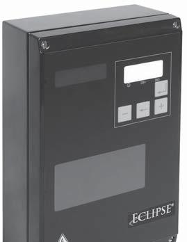
5 Introduction 1 Programmable parameters Continuous or intermittent operation Communication options Modulating output control (0-10V, 4-20 ma or PWM) Two programmable flame sensor inputs Programmable "operation" output terminal Advanced diagnostics Runtime, lifetime and cycle counters History shows last 10 errors Software for status, settings and logging CE, FM, UL, CSA, GOST-R, AGA and SIL 3 approvals Description Features Type 1 Type 2 Integral Display Type 3 Type 2 Modulating The T600 microprocessor-controlled automatic fl ame safeguard control is for intermittent and continuous operation of gas, oil or combination gas / oil burners. The fl ame is monitored by either an ionization (fl ame rod) input, dual contacts (NO and NC), a single contact (NO) or a combination of the ionization and contact inputs. This dual monitoring capability combined with confi gurable sequences enables supervision of burners with two fl ame sensor positions, long line burners, redundancy for burners with a moving fl ame, and two burners from a single valve train (one-down-all-out). The program sequence and timings can be confi gured to match the application. The settings are protected by passwords against unauthorized access. All settings for the T600 can be made by means of a laptop / PC via the VisionBox or through the integral display (certain models only). For operation in burner networks, Profi bus or Modbus communication is available as an option. T600 Types Type 1 without display This version may be used if accessing information via the display is not required or limited state/fault information is acceptable. Type 2 with integral display This version gives local display of detailed information. Type 2 with modulating capabilities This version allows for modulating control of process components. Type 3 with metal housing and integral display This version provides an extra level of environmental protection for particularly demanding installations. Application For industrial burners, with or without pilot (start gas), for ovens and furnaces meeting the requirements of NFPA 86 and for industrial thermoprocessing equipment meeting the requirements of EN or ISO series. Approvals CE, FM, UL, CSA, GOST, AGA (See page 18 for details) 5
6 T600 Options Type 1 Purge / No Purge Type 2 Purge / No Purge Modulating Type 3 Purge / No Purge Modulating No Display Communications Special Order Display Standard Communications Option Display Standard Communications Included Display Standard Communications Option Display Standard Communications Included Integral Display Yellow Red The integral display provides information through various modes: Operation Display Current operating state Program state Bus address Info Display Flame quality value Resettable counters for start-up, operating hours and operating cycles Error Display Automatic activation of error messages Additional information about faults Query of the last ten faults Parameter Display Password-protected access for qualifi ed personnel to make parameter adjustments Includes important parameters such as: - Pre-purge - Safety time for startup phase - Post-purge time - Behavior after flame lift-off - Operating modes of V1 and V2 - Continuous or intermittent operation 6
7 Status Information Designation Description Visible via VisionBox Visible via Display General Information Lockout System is locked, error code LED State Number Current state of the system, key combination + and - 7-segment Current Access Level For parameter changes via password entry Flame Flame detected LED Manual Mode System in manual mode 7-segment Flame Quality Value > 49 good fl ame (ionization) Info Bus Connection Present Communication via Profi bus, Modbus 7-segment Burner Start Request Signal combination from bus setpoint input and hardware LED input Inputs Air Pressure Switch Signal to terminal 18 Flame 1 Signal from fl ame 1 input, terminal 5 Flame 2 NO Signal from fl ame 2 NO input, terminal 16 Flame 2 NC / Gas Pressure Switch / POC Hardware Input for Burner Start Outputs Signal from fl ame 2 NC input, gas pressure switch or POC, terminal 17 On / off signal for burner start, terminal 19 Gas valve V1 Pilot valve, terminal 13 Gas valve V2 Main valve, terminal 14 Ignition Igniter or ignition transformer, terminal 15 Fan Combustion air blower starter, terminal 8 Counters Time Counter / Lifetime Counter Time since switching on the power Runtime Meter Fixed operating time Resettable Runtime Meter Resettable via VisionBox and display Info Start Counter Fixed counter of startups Resettable Start Counter Resettable via VisionBox and display Info Switching Cycles Counter V2 Count of main valve cycles Info Internal Information State Timer in Minutes Displayed state timer runs in minutes, otherwise in 1/16s. Initialization Phase The fl ame safeguard is being initialized Multi-function Switch "ON" when reset button is pressed Access Level Change CCC or value fl ashes on display, key expected 7-segment Safety Switch-off Flag System is locked Error Index Internal error counter Remaining State Time if unlimited remaining time Cycl. State Counter Counts in 1/128s cycle Processor Load Represents percentage of processor capacity LED: Indicated by one of the 3 LEDs on the display 7-segment: Indicated by one or several characters of the 7-segment display Info: Displayed in informative display mode 7
8 Accessories UV 41HE / UV 42 UV fl ame detectors. Suitable for intermittent operation. UV 41HE - Ionization output UV 42 - Contact output Suitable for continuous operation in conjunction with shutter module UV 4x EM 1/1 and T600 with self-check control option. FLW 41I Flame detector module used when a second ionization fl ame detector is required. The FLW 41I is connected to the second fl ame sensor input of the T600. 8
9 Configured Part Number T600rr rr = revision number NOTE: Not all functions or capabilities are shown here. Contact Eclipse for additional options Customer. Standard Product Options 2 - Model 1 No-Purge 2 Purge 3 Analog Modulating Control 3 - Type 1 No Display 2 Integral Display 3 Metallic with Display 4 - Voltage 1 115VAC 2 230VAC A B C 5 - Ignition Configuration Interrupted Pilot Direct Spark / Intermittent Pilot High-Low A B C D E F G H J K 6 - Application Single Burner, Aux (NC) Input for POVC Single Burner, Aux (NC) Input for Gas Switch (No POVC) Dual Burners, Aux (NC) Input for POVC Dual Burners, Aux (NC) Input for Gas Switch (No POVC) Line Burner and 2 Flame Sensors, Aux (NC) Input for POVC Line Burner and 2 Flame Sensors, Aux (NC) Input for Gas Switch (No POVC) Redundant: Pilot 1 or 2, Main 1 or 2, Aux (NC) Input for POVC Redundant: Pilot 1 or 2, Main 1 or 2, Aux (NC) Input for Gas Switch (No POVC) High-Low Burner, Aux (NC) Input for POVC High-Low Burner, Aux (NC) Input for Gas Switch (No POVC) 7 - Pre-Purge Time 3 3 seconds A 10 seconds C 20 seconds D 30 seconds F 60 seconds K 120 seconds M 240 seconds P 360 seconds R 600 seconds T 900 seconds U 1200 seconds X No Purge 9
10 Configured Part Number (Continued) T600rr rr = revision number First Safety Time (Pilot TFI) 3 3 seconds 5 5 seconds A 10 seconds B 15 seconds 9 - Second Safety Time (Main TFI) 3 3 seconds 5 5 seconds A 10 seconds B 15 seconds X None (Direct Spark / Intermittent Pilot) 10 - FFRT - Pilot and Main 1 1 seconds 3 3 seconds 11 - Post Purge Time 3 3 seconds A 10 seconds D 30 seconds F 60 seconds X None A B C D E J K L M N X 12 - Extended Capabilities Self-Check Scanner Control Only Modbus Communications Only Profibus Communications Only Modbus Communications and Self-Check Scanner Control Profi bus Communications and Self-Check Scanner Control Modulating with Self-Check Scanner Control Only Modulating with Modbus Communications Only Modulating with Profi bus Communications Only Modulating with Modbus Communications and Self-Check Scanner Control Modulating with Profi bus Communications and Self-Check Scanner Control None 13 - Modulating Control Signal A PWM B 0-10 VDC C 4-20 ma X None 14 - Actuator Stroke Time C 12.5 seconds D 15 seconds F 25 seconds G 30 seconds J 45 seconds M 60 seconds X None 10
11 A Typical System Diagram Burner with Pilot Ignition P L A M V1 V2 B A FSG Combustion Air Main Air Pilot Air Flame Detector Natural Gas B P L S S Pilot Gas V2 S S V1 B P H Main Main Gas After the burner start signal, the fan is switched on and the air pressure is checked by the pressure switch. After the pre-purge time has lapsed, the ignition is switched on and the pilot valve(s), V1, is opened for the trial for ignition. After proof of pilot fl ame, the main valve(s), V2, is opened. See section 5, "Operational State Overview" for details on the complete sequence. Burner with Direct Spark / Intermittent Pilot Ignition Natural Gas FSG P L S S P H Flame Detector V1 V2 Burner P L A M IG Combustion Air After the burner start signal, the fan is switched on and the air pressure is checked by the pressure switch. After the pre-purge time has lapsed, the ignition is switched on and the two valves V1 and V2 are opened together. See section 5, "Operational State Overview" for details on the complete sequence. 11
12 High-Low or Line Burner Combustion Air A Low Fire - Air V1 V2 High Fire - Air A P L M A FSG B C D 1 2 E Natural Gas B P L S S S S Low Fire - Gas V2 B V1 P H 3 High Fire - Gas 4 C D Low Fire Flame Detector 3 2 High Fire Flame Detector E IG 1 4 Main After the burner start signal, the fan is switched on and the air pressure is checked by the pressure switch. After the pre-purge time has lapsed, the ignition is switched on and the low fi re valve, V1, is opened for the trial ignition. V1 stays open and V2 will open and close depending on the communication bus command. If two fl ame detectors are used, a valid signal from either detector will allow operation. A loss of signal from both detectors causes a shutdown. See section 5, "Operational State Overview" for details on the complete sequence Dual burner with Direct Spark / Intermittent Pilot Ignition of Main Gas Flame Flame Detector FSG Natural Gas P L S S P H IG Flame Detector P L A M V1 V2 IG Combustion Air After the burner start signal, the fan is switched on and the air pressure is checked by the pressure switch. After the pre-purge time has lapsed, the ignition is switched on and the two valves V1 and V2 are opened together. On failure of either fl ame detector, both V1 and V2 are closed and both burners are shut-off. NOTE: Dual burner pilot ignition is also possible. See section 5, "Operational State Overview" for details on the complete sequence 12
13 Modulating Burner with Pilot Ignition D TC A P L Main Air M D C C A V1 V2 B FSG Flame Detector Combustion Air Pilot Air Natural Gas B P L S S Pilot Gas V2 S S V1 B P H Main Main Gas After the burner start signal, the fan is switched on and the air pressure is checked by the pressure switch. The actuator drives to the high fi re position and remains here until the prepurge time has elapsed. The actuator drives to the low fi re position, the ignition is switched on and the pilot valve(s),v1, is opened for the trial for ignition. After proof of pilot fl ame, the main valve(s), V2, is opened and the burner will begin modulation based on feedback from the temperature controller. See section 5, "Operational State Overview" for details on the complete sequence Modulating Burner with Direct Spark / Intermittent Pilot Ignition Natural Gas B A TC FSG P L S S P H Flame Detector V1 V2 Burner P L A M B IG Combustion Air After the burner start signal, the fan is switched on and the air pressure is checked by the pressure switch. The actuator drives to the high fi re position and remains here until the prepurge time has elapsed. The actuator then drives to the low fi re position, the ignition is switched on and valves V1 and V2 are opened together for the trial for ignition. After proof of pilot fl ame, valves V1 and V2 will remain open and the burner will begin modulation based on feedback from the temperature controller. See section 5, "Operational State Overview" for details on the complete sequencez 13
14 Technical Data 2 General Mechanical Protection Rating of the Plastic Housing Protection Rating of the Metal Housing Ambient Temperature Type 1: IP 42 (approximately equivalent to NEMA 12) Not UV (sunlight) protected Type 2: IP 54 (approximately equivalent to NEMA 3) Not UV (sunlight) protected Type 3: IP 65 (approximately equivalent to NEMA 4) Not UV (sunlight) protected ATTENTION: use suitable cable screw connectors only -20 C C (-4 F F) (UL Approval) -40 C C (-40 F F) -40 C C (-40 F F) Storage and Transport Humidity < 95%, no condensation permitted (tested to DIN ) Useful Life of Switching Outputs Minimum 250,000 switching operations Mounting Position as desired Approximate Dimensions in mm (inches) (excluding cable screw connector) Type 1 (L x H x T): x x 77 (6.0 x 5.9 x 3.0) Type 2 Purge / No Purge (L x H x T): x x 77 (6.0 x 6.0 x 3.0) Type 2 Modulating (L x H x T): 190 x x 170 (7.5 x 6.0 x 6.7) Type 3 (L x H x T): 160 x 240 x 80 (6.3 x 9.5 x 3.2) Weight in kg (lbs) Type 1: 0.82 (1.8) Type 2 Purge / No Purge: 0.82 (1.8) Type 2 Modulating: 1.42 (3.13) Type 3: 2.2 (4.85) Display Type 1: 2 LEDs - 1 red, 1 yellow Type 2: 3-digit 7-segment display plus 3 LEDs Type 3: 3-digit 7-segment display plus 3 LEDs 14
15 General Electrical Rated Voltage 230 VAC -15% % or 115 VAC -15% %, depending on the version Frequency Fuse Isolation Electrical Connection Power Consumption (own consumption) 50 Hz Hz 6.3A slow-blow fuse or 10A fast-blow fuse, integrated, exchangeable No galvanic isolation between mains and 24 VDC or 5 VDC ATTENTION: Assure correct line voltage and protective earth conductor connection according to the wiring diagram. The contact protection for the UV sensor must be guaranteed by mounting it in the operating equipment. Assure protection for the wiring and connector of the UV sensor through proper mechanical mounting and support. All connecting wires must be suitable for maximum expected temperatures and must not be rated less than 167 F (75 C). Maximum 10W Typically 115V 230V Standby 1.5W W Operation 3.4W W With communications or self-check option: Standby 3.3W W Operation 5.4W W Designation Type of Input Electrical Data L1 Connection Over Replaceable Fuse Type 1 / Type 2 TWI Interface Type 1 / Type 2 Switch for Parameter Mode Type 1 / Type 2 User Interface Type 1 (without display) User Interface Types 2 and 3 (with display) Power supply TWI 2 - position switch One momentary switch Four buttons L1 protected by integrated fuse, 6.3A slow-blow or 10A fast-blow Connection only for VisionBox and parameterization box NOT galvanically isolated! ON / OFF switch on fl ame safeguards (may only be switched after having removed the fl ame safeguard from the base) Confi rm or reset Reset, back, plus and minus Spark generator connection The T600 does not include an ignition transformer. For suitable ignition transformers, see Datasheet 841 at ATTENTION: A special ignition transformer is required depending on the electrode arrangement (i.e. for singleelectrode operation). 15
16 Outputs Safety- Designation Related V1 Main Gas Valve Relay contact Maximum 100 m (328 ft) Type of Output Line Length Electrical Data V2 Safety Gas Valve Relay contact Maximum 100 m (328 ft) Ignition Fan Operation Fault Flame Detector Supply Modulating Outputs Fan Activation - Relay contact Maximum 100 m (328 ft) - Relay contact Maximum 100 m (328 ft) - Relay contact Maximum 100 m (328 ft) - Relay contact Maximum 100 m (328 ft) - For UV 41HE or UV 42 PWM 4 khz, without detection of speed feedback Maximum 100 m (328 ft) Maximum 10 m (32.8 ft) 115/230 VAC / 2A cos ϕ = 1 (resistive) Minimum load 0.5W 115/230 VAC / 2A cos ϕ = 1 (resistive) Minimum load 0.5W 115/230 VAC / 1A cos ϕ = 0.4 corresponds to 115/230 VAC / 2.5A cos ϕ = 1 (resistive) 115/230 VAC / 1A cos ϕ = 0.4 corresponds to 115/230 VAC / 2.5A cos ϕ = 1 (resistive) 115/230 VAC / 1A cos ϕ = 1 (resistive) 115/230 VAC / 1A cos ϕ = 1 (resistive) 230 VAC / 10 ma* 24 VDC (3 lines: GND, +24 VDC, PWM control signal) Frequency Converter V Maximum 10 m (32.8 ft) 10 VDC Activation Activation of Shutter - Switching contact Maximum 100 m (328 ft) 24 VDC *The fl ame detector is always supplied with 230 VAC (even the 115 VAC version) via the T600 fl ame detector power supply, pin 7 The sum of the currents of all safety-related loads must not exceed 5 A! The sum of the currents of all loads must not exceed the installed fuse value 16
17 Inputs Designation Type of Input Line Length Electrical Data Safety Chain Voltage-free (dry-contact) Maximum 100 m (328 ft) 115 / 230 VAC / max. 10 A Flame Detector 1 (Ionization) Flame Detector 2 NO Ionization for one- or twoprobe operation Switching contact Maximum 10 m (32.8 ft)* Maximum 100 m (328 ft) Threshold: ~ 1.2 μa Short-circuit current to N: 280 μa 115 / 230 VAC normally open Flame Detector 2 NC 115 / 230 VAC Switching contact Maximum 100 m (328 ft) normally closed Burner Start Switching contact Maximum 100 m (328 ft) 115 / 230 VAC Air Pressure Switch Switching contact Maximum 100 m (328 ft) 115 / 230 VAC Remote Unlocking Switching contact Maximum 100 m (328 ft) 115 / 230 VAC Modulating Inputs "High Fire" Feedback Switching contact Maximum 100 m (328 ft) 115/230 VAC "Low Fire" Feedback Switching contact Maximum 100 m (328 ft) 115/230 VAC Power + Switching contact Maximum 100 m (328 ft) 115/230 VAC Power - Switching contact Maximum 100 m (328 ft) 115/230 VAC *If the line length must be greater than 10 m (32.8 ft), an additional fl ame detector should be used. Flame Signal Strength (current) vs. T600 Display 25 Flame Signal Strength (μa) digits T600 Display The quality of the fl ame signal is displayed for fl ame detector 1 as a number between 0 and 58. Evaluation of the fl ame signal is only possible with ionization fl ame monitoring. When using the UV 42, the maximum value is always displayed. 17
18 Approval Overview Approval Overview Order No. CE FM UL Recognized CAN/CSA- C22.2 GOST T600 Type 1 / AC 115V Confi gured x x x x x x T600 Type 1 / AC 230V Confi gured x x x x x T600 Type 2 / AC 115V Confi gured x x x x x x T600 Type 2 / AC 230V Confi gured x x x x x T600 Type 3 / AC 115V Confi gured x x x x x x T600 Type 3 / AC 230V Confi gured x x x x x Flame detector FLW 41I x x x x UV 41HE See page 104 x x x x x x UV 42 See page 106 x x x x x x UV 4x EM 1/ x x x x x x AGA Approvals EC type-examination certifi cate according to the EC Gas Appliances Directive: T600 Series CE-0085 BU 0487 EC type-examination certifi cate according to the EC Pressure Equipment Directive: T600 Series CE0036 FM Approved to FM 7610 UL Recognized Component per UL 372, UL 1998 and CAN/CSA-C22.2. GOST/Rostechnadzor Suitable for applications up to SIL3 Meets the requirement according to IEC (2nd ed. 2011) Certifi ed by TÜV Süd AGA Certifi ed to AS and EN T600 Series from V1.1 UV 4x UV 4x-EM1/1 (Shutter) Components SIL SFF PFH x Ionization input % 1.80E-09 x Input Flame Sensor 2 NO, Flame Sensor 2 NC, Air pressure % 1.80E-09 switch and remote unlocking x x UV 41HE + ionization input % 1.50E-07 x x x x x x x x SIL (Safety Integrity Level) UV 42 + input Flame Sensor 2 NO UV 4x-EM1/1 (shutter) + UV 41HE + ionization input UV 4x-EM1/1 (Shutter) + UV 42 + input Flame Sensor 2 NO % 1.51E % 3.15E % 3.15E-08 18
19 Dimensions in mm (inches) Type 1 Purge / No Purge Dimensions 75.2 (3.0) (No screw connections on top) (5.9) 8X Ø16 (0.6) Figure (6.0) Type 2 Purge / No Purge Dimensions 75.5 (3.0) (No screw connections on top) (6.0) Ø15.7 (0.6) for communications connection 8X Ø16 (0.6) Figure (6.0) 19
20 Type 2 Modulating Dimensions (6.0) 21X Ø16 (0.6) 190 (7.5) 170 (6.7) (No screw connections on top) Figure
21 Type 3 Purge / No Purge and Modulating Dimensions 37.5 (1.5) 40.5 (1.6) 26 (1.0) 12 (0.5) 18.5 (0.7) 32 (1.3) 2X M32x1.5-6H 3X M16x1.5-6H Section A-A View shown with door removed 18.5 (0.7) 160 (6.3) 80 (3.2) 240 (9.4) A Figure 2.4 A 21

22 Installation 3 Safety Warnings Important notices for safe operation of the fl ame safeguard will be found in this section. To avoid personal injury, damage to property or the facility, the following warnings must be observed. Read this entire manual before attempting to start the system. If any part of the information in this manual is not understood, contact Eclipse before continuing Danger The Flame Safeguard is a safety device. Do not open, interfere with or modify the unit. Caution Use of this product in the European community shall only be deployed in a manner that meets the applicable EC directives and laws. Warning All activities (mounting, installation, and service) must be performed by qualifi ed staff. Protect against electrical shock before making any wiring changes in the connection area by turning off the main power supply. Ensure that the power cannot be inadvertently switched on again and that it is indeed off. Each time work is carried out such as mounting, installation, or service, check that wiring and parameterization is correct and perform safety checks. If the housing or area near the operating panel is damaged, the unit must be immediately put out of operation or there may be a risk of electrical shock. Do not use any tools or pointed objects when pressing the buttons on the display. If the fi lm on the operating panel is damaged, there is a risk of electrical shock. Fall or shock can adversely affect the safety functions. Such burner controls must not be put into operation, even if they do not appear to be damaged. If applicable, the dataline for the VisionBox PC interface must be connected or disconnected only when the main supply voltage is off to guard against electrical shock in case of an internal fault. Power must be cycled on the unit to register a switch position change. Do NOT remove or insert unit while power is applied! Capabilities Adjustment, maintenance and troubleshooting of the mechanical parts of this system should be done by qualifi ed personnel with good mechanical aptitude and experience with combustion equipment. Operator Training The best safety precaution is an alert and competent operator. Thoroughly instruct operators so they demonstrate an understanding of the equipment and its operation. Replacement Parts Order replacement parts from Eclipse only. Disposal The unit contains electrical and electronic components and must not be disposed of together with domestic waste. Local and currently valid legislation must be observed WARNING: Keep units straight when pulling apart. If bent, the circuit board may become damaged. Do not touch the circuit board. Oils from your fi ngers may prevent electrical conductivity. Figure
23 Types 1 and 2 Purge / No Purge Installation Options Mounting - Base surface mounting: use two M4 or #8 screws. Thickness through the base is 9 mm (0.34 inches). - DIN rail mounting (locking the base into place on a standard 35mm DIN rail). See page 26 for details. NOTE: When knocking out base holes for use with the conduit adapter, be sure to use every other hole (1.5) 100 (3.9) Base Surface Mounting Figure 3.2 DIN rail mounting Figure
24 Type 2 Modulating Installation Options Mounting - Base surface mounting: use two M4 or #8 screws. Thickness through the base is 9 mm (0.34 inches). NOTE: When knocking out base holes for use with the conduit adapter, be sure to use every other hole. 122 (4.8) 166 (6.5) Figure
25 Wiring Accessories for Field Mounting These accessories apply to all Purge / No Purge models and the Type 2 Modulating model if the T600 is not mounted in an enclosure. Part Number Description Brass M x 1/2" NPT conduit adapter fi tting Sealing washer for use with M Lock nut for use with Lock Nut 5 (0.2) Ø20 (0.8) Sealing Washer 2 (0.8) 22 (0.9) M16 x 1.5-6H Ø16 (0.6) Ø16 (0.6) 31.5 (1.2) 9.3 (0.4) 1/2 NPT Conduit Adapter Fitting Ø16 (0.6) 25


26 Types 1 and 2 Purge / No Purge Installation on DIN Rail 2. Push the base downward to compress the springs. 1. Guide the DIN rail upper lip into the mounting tabs containing the compression springs. 3. While compressing the springs, rotate the controller base to allow full engagement of the locking tabs. Figure 3.5 Removal from DIN rail 1. Push the base downward to compress the springs. 2. While compressing the springs, rotate the controller base away from the DIN rail to disengage the locking tabs. Figure When clear off the bottom rail, lift. 26
27 Type 3 Installation Options - Direct screw mounting connection of the housing on the installation surface using M4 or #8 screws; thickness through the base is 12 mm (0.5 inches) M4 M4 225 (8.9) M4 123 (4.8) Figure 3.7 M4 27
28 Wiring Terminal Description and Parameter Index Terminal Description Modulating Associated Parameter 1 Main control power is connected to Terminal 1. This terminal should be powered at all times during burner sequencing. Terminal 2 must be jumpered to Terminal 1 at all times. Terminal 2 is not 2 used for any other purpose. The factory installed jumper between Terminal 1 and Terminal 2 must not be removed for any purpose. 3 The neutral side of the power supply is connected to Terminal 3. 4 Terminal 4 must be grounded to the Earth Ground bar G for single igniter / fl ame rod (unirod) operation. When individual / separate igniter and fl ame rod are used the connection between Terminal 4 and Earth Ground bar G may need to be disconnected. Terminal 5 is used for connecting a fl ame rod or a fl ame detector that 5 provides a rectifi cation ionization type output. 6 Not used Terminal 7 provides a 230 VAC / 10 ma power supply for use with the T600 UV Scanner fl ame detectors. This power supply is always 230 VAC even with the 115 VAC T600 version! It can supply two UV detectors (UV 41HE and UV 42) or one fl ame detector (FLW 41I). Terminal 8 is relay contact output for operating the fan either directly or through a motor starter depending on the power requirements of the fan. This terminal is the output (supply voltage) to the safety switches. All safety limits should be wired in series between Terminal 9 and Terminal 10. Safety limits may include but are not limited to the low gas pressure switch, high gas pressure switch, and high temperature limit. This terminal is the input (signal voltage) from the safety switches. All safety limits should be wired in series between Terminal 9 and Terminal 10. Safety limits may include but are not limited to the low gas pressure switch, high gas pressure switch, and high temperature limit. P33, P36 P12, P15, P20 P12, P15, P20 11 Voltage output for burner operation. Timing is parameter selectable. P19 12 Voltage output for alarm Valve 1 represents the fi rst valve(s) to energize in the ignition sequence of a burner system. This output is used to energize the pilot valves during the pilot trial for ignition sequence. For direct spark / intermittent pilot ignition burners, this output energizes the main valves. Valve 2 represents the second valve(s) to be energized during the burner ignition sequence. In piloted burners, this contact would be used to energize the main gas valves during the main fl ame trial for ignition period. Terminal 15 provides the power for the ignition transformer during the ignition sequence. See Datasheet 841 at ignition_transformers for more information. Terminal 16 provides for the use of a second relay output type fl ame sensor device with a normally open contact that closes when a fl ame is present. Terminal 17 provides for the use of a second relay output type" fl ame sensor device with a normally closed contact that opens when a fl ame is present. Alternatively, Terminal 17 can be used for a POVC input when POVC switch(s) are used on the safety shutoff valves. P31, P38 P38 P31 P18, P33, P36 P18, P22, P33, P36 18 Terminal 18 is for the combustion air switch input. P16 19 Burner startup is initiated when power is applied to this terminal. Removal of power results in a normal shutdown. P52 20 This input allows for reset of the control from a remote location. 21 Terminal 21 is the common for Relay 1, Relay 2 and Relay 3. P249 28
29 Terminal Description Modulating Associated Parameter 22 Terminal 22 is the analog switching on/off high fi re relay (Relay 3). P Terminal 23 is the analog switching on/off low fi re relay (Relay 2). P Terminal 24 is the analog switching on/off automatic relay (Relay1). P Not used Terminal 26 must be connected to the neutral side of the power supply if 26 P249 terminals are used. 27 Terminal 27 is the low fi re feedback switching input. P Terminal 28 is the high fi re feedback switching input. P Terminal 29 is the heat/power decrease switching input. P Terminal 30 is the heat/power increase switching input. P Not used Terminal 32 is the ground (signal -) for terminals 33 and 34 if the unit is confi gured for analog output control (PWM, 0-10 V, 4-20 ma). Terminal 33 is the analog output (signal +) if the unit is confi gured for analog output control. Terminal 34 is the VCC out ( VDC) if the unit is confi gured for 34 PWM/4-20 ma analog output control and 10 V out if the unit is configured for 0-10 V analog output control. 35 Not used 36 Terminal 36 is the ground (shutter -) for terminals P Terminal 37 is the VCC (5 V) bus termination if utilizing the integrated Profibus or Modbus communications. Terminal 38 is the data line plus (B conductor) if utilizing the integrated Profibus or Modbus communications. P240 - P249 P240 - P249 P240 - P Terminal 39 is the data line minus (A conductor) if utilizing the integrated Profibus or Modbus communications. P11 40 Terminal 40 is the shutter +. P21 P11 P11 29
30 Purge / No Purge Wiring Examples Typical NFPA86 Wiring Incoming single phase voltage Internally fused (6.3A slow or 10A fast) Proof of Valve Closure Interlocks Air Flow Switch 115 VAC 50/60 Hz or 230 VAC 50/60 Hz (Model Dependent) Note: Power must be applied to terminal 1 at all times during burner sequencing Flame sensor 1 (Ionization) Safety chain HTL LGP HGP Flame sensor 2 (relay type) Stop/Start Reset Attach neutral at bar in mounting base Attach ground at bar in mounting base UV 41HE, UV 42, FLW 41I power supply* Burner Alarm Fan M Burner On V1 - Pilot Valve V2 - Main Valve Ignition *Terminal 7 s output is always 230 VAC Typical EN746-2 Wiring Incoming single phase voltage 115 VAC 50/60 Hz or 230 VAC 50/60 Hz (Model Dependent) Internally fused (6.3A slow or 10A fast) Note: Power must be applied to terminal 1 at all times during burner sequencing Attach neutral at bar in mounting base Attach ground at bar in mounting base Flame sensor 1 (Ionization) 5 UV 41HE, UV 42, FLW 41I power supply* 7 Fan 8 M Safety chain 9 HTL Interlocks 10 Burner On 11 Burner Alarm V1 - Pilot Valve V2 - Main Valve Ignition LGP HGP Flame sensor 2 (relay type) Air Flow Switch *Terminal 7 s output is always 230 VAC Stop/Start Reset 20 Wiring Safety Risk of fatal electric shocks! You must interrupt the power supply before removing the hood. After having removed the hood, you might get in contact with the electrical connections in the terminal socket. Do not remove the jumper between terminals 1 and 2, which was mounted in the factory. It is required for the intended use of the automatic gas burner control system. 30
31 Modulating Wiring Examples Incoming single phase voltage 115 VAC 50/60 Hz or 230 VAC 50/60 Hz (Model Dependent) Internally fused (6.3A slow or 10A fast) 1 Note: Power must be applied to terminal 1 at all times during burner sequencing 2 Attach neutral at bar in mounting base 3 4 Attach ground at bar in mounting base Flame sensor 1 (Ionization) 5 UV 41HE, UV 42, FLW 41I power supply* 7 Fan 8 M Safety chain 9 HTL LGP HGP Interlocks 10 Burner On 11 Burner Alarm 12 V1 - Pilot Valve 13 V2 - Main Valve Ignition Flame sensor 2 (relay type) 16 Proof of Valve Closure 17 *Terminal 7 s output is always 230 VAC Air Flow Switch 18 Stop/Start 19 Reset 20 Sensor Temperature Controller L1 N 4-20 ma or 0-10 VDC T/C Input Shielded Cable Actuator L1 N Control Terminals Position Feedback Wiring Safety Risk of fatal electric shocks! You must interrupt the power supply before removing the hood. After having removed the hood, you might get in contact with the electrical connections in the terminal socket. Do not remove the jumper between terminals 1 and 2, which was mounted in the factory. It is required for the intended use of the automatic gas burner control system HF LF LF HF 31
32 Incoming single phase voltage 115 VAC 50/60 Hz or 230 VAC 50/60 Hz (Model Dependent) Internally fused (6.3A slow or 10A fast) 1 Note: Power must be applied to terminal 1 at all times during burner sequencing 2 Attach neutral at bar in mounting base 3 4 Attach ground at bar in mounting base Flame sensor 1 (Ionization) 5 UV 41HE, UV 42, FLW 41I power supply* 7 Fan 8 M Safety chain 9 HTL LGP HGP Interlocks 10 Burner On 11 Burner Alarm 12 V1 - Pilot Valve 13 V2 - Main Valve Ignition Flame sensor 2 (relay type) 16 Proof of Valve Closure 17 *Terminal 7 s output is always 230 VAC Air Flow Switch 18 Stop/Start 19 Reset 20 Sensor Temperature Controller L1 Alarm Contacts N NO C NO T/C Input Actuator L1 N Wiring Safety Risk of fatal electric shocks! You must interrupt the power supply before removing the hood. After having removed the hood, you might get in contact with the electrical connections in the terminal socket. Do not remove the jumper between terminals 1 and 2, which was mounted in the factory. It is required for the intended use of the automatic gas burner control system Sensor 4-20 ma or 0-10 VDC 32
33 Flame Sensor and Ignition Wiring Examples Single-Electrode Operation Ionization Flame Safeguard Connection 15: Ignition 3: N Flame 4: PE 5: ION* 7: Power Sensor Power 16: Flame Sensor 2 NO *Use proper ignition transformer when using single-electrode ionization. Figure 3.8 Two-Electrode Operation Ionization Flame Safeguard Connection 15: Ignition 3: N Flame 4: PE 5: ION 7: Power Sensor Power 16: Flame Sensor 2 NO Figure 3.9 Flame Detector UV 41HE Flame Safeguard Connection 15: Ignition 3: N UV 41HE Flame *UV 41 HE PIN terminals 4: PE 5: ION 7: Power Sensor Power GND* N* Out* L* 16: Flame Sensor 2 NO Figure
34 FLW 41I Operation Flame Safeguard Connection *FLW 41I PIN terminals 15: Ignition 3: N Flame 4: PE 5: ION FLW 41I : Power Sensor Power Terminal 3* Terminal 2* 16: Flame Sensor 2 NO Terminal 1* NOTE: See Figure 9h-4 (page 110) for complete wiring of FLW 41I Figure 3.11 Flame Detector UV 42 Flame Safeguard Connection *UV 42 PIN terminals 15: Ignition 3: N Flame 4: PE GND* N* 5: ION 7: Power Sensor Power 16: Flame Sensor 2 NO Out* L* Figure
35 Combustion Air Switch Input Wiring Examples 8: Fan 18: Air Switch If the system does not require an air switch input, parameter P16 can be set to 0.1 or terminals 8 and 18 can be wired together as shown in Figure Figure 3.13 To Fan Output Terminal Air Switch Open FAN 3-Way Solenoid Valve De-energized To Fan Output Terminal To Burner Air Switch Closed If the combustion air blower is not controlled by Terminal 8, a three-way solenoid valve must be installed between the air switch port and the blower pressure sensing port. The valve de-energized state shall vent the air switch port to ambient pressure. The valve energized state shall connect the air switch port to the blower pressure sensing port. The valve shall be powered by Terminal 8. FAN To Burner 3-Way Solenoid Valve Energized Figure
36 Functional Overview 4 Reset function If the fl ame safeguard is locked (state 0, error), unlock it by pressing the reset button, the hard-wired reset input, or via the fi eldbus (Profi bus, Modbus, etc.). The reset must last a minimum of 0.5s (maximum 5s). The number of resets is limited to 5 in 15 minutes. Reset will be allowed only after waiting 15 minutes while the fl ame safeguard is powered. The waiting time is 3 minutes for each reset or 15 minutes. Extended reset The described limitation of 5 reset operations in 15 minutes can be cleared by means of "Extended Reset". To do this, the reset key must be pressed for at least 5s (maximum 10s); after 5s the display begins to fl ash. The "Extended Reset" is active in all operational states of the fl ame safeguard, which means an operating burner will be shut down and restarted with an extended reset. Extended reset is not possible via the hard-wired reset input or via fi eldbus modules. 36


37 Parameter Mode - Manual and Automatic Operation A switch on the bottom of the fl ame safeguard is used for switching between parameter and automatic mode (see Figures 4.1 and 4.2). WARNING: Power must be cycled on the unit to register a switch position change. Do NOT remove or insert unit while power is applied! With the switch in the "Auto" position, the flame safeguard is working in normal operation. If a monitored parameter was changed and not properly released, the fl ame safeguard indicates an error by showing "F 60" on the display and "0x60" in the VisionBox. Types 2 and 3 After connecting the main supply in Parameter mode, a message is prompted on the display requesting you to enter the password. Enter the password for service or OEM level. After having changed the access level, the selected parameters are activated one after the other. TWI Connector VisionBox See section 6, "Parameter Overview" for parameters and sequence. The parameter values may be modifi ed by pressing the + and - keys. The enter key is used for saving the displayed value. Press the back key ( ) to return to the previous position or parameter. As the display uses only two digits, values greater than 99 will show "- -" and must be shown in subsequent stages (see page 61 for an example). Manual Operation After parameters are set, there is an automatic start for checking the parameter values. The program stops in pause states; press a key to proceed (Hx is displayed). The set parameter values will be applied or released when the H5 state is reached. Figure 4.1 Purge / No Purge Types 1 and 2 Parameter switch Left: "Auto" or "Run" position Right: "Para" or "Program" position TWI Connector VisionBox If you do not press any key for 30 minutes in parameter mode, the program tries a restart. "Auto" Operation Figure 4.2 Type 3 Parameter Switch Location 37
38 Operational State Overview 5 Sequence chart The program sequence should be customized by parameter confi guration at Eclipse, Inc when ordering a T600. Additional modifi cations to the parameter settings may be conducted in the fi eld by authorized Eclipse service personnel only. ATTENTION All modifications must comply with the requirements of the valid standard and application. Eclipse shall not assume any liability for material or personal damage caused by unauthorized or improper use of the flame safeguard. NOTES (see fl ow charts on the following pages): *1 Monitoring of the air pressure switch depends on the operating mode set in P16. *2 V1 can be deactivated via P38 after the second safety time (= interrupted start gas) *3 The two inputs Flame 1 and Flame 2 can be activated or deactivated independently of one another per parameters P18, P33, P36 for phase 1 and phase 2. *4 Both fl ame inputs must be off! *5 With "Follow-up", it will run 15 minutes of follow-up after a regular switch-off. After 24 hours OFF, the signal will be activated for 1 minute to prevent blocking a circulation pump in a heated liquid application. *6 The input "Flame 2 NC" can also be confi gured as gas pressure switch. The gas pressure switch tolerates faulty signals of up to 1s. *7 The follow-up time starts during the "Post-purge" state. If the post-purge is greater than / equal to the follow-up time, the "Follow-up time" state will be skipped. *8 The fl ame safeguard can also run in High-Low operation (P38=2). The selection of High-Low will be made via the fi eldbus. V1 is always open (= Low Fire). V2 will open after a fi eldbus setpoint input (= High Fire). In the operating modes "interrupted start gas" (P38=0) and "permanent start gas" (P38=1), V2 is always ON. *9 The input "Flame 2 NC" can also be confi gured as Proof of Valve Closure (POVC) as a function of output V1 or V2. The POVC tolerates faulty signals of up to 1s. *10 In the operating mode P38 = 2 (High-Low operation), the second safety time is skipped, and the fl ame safeguard goes from "Pause 3" directly to the "Operation" state! *11 The after-burning time starts already in the Post-Purge state. When the post-purge becomes larger or equal to the after-burning time, the After-Burning Time will be skipped. *12 Monitoring of the High Fire input will not be started until the time defi ned in P248 has expired. *13 The ignition speed is already set before the end of the pre-purge time, this time being defi ned in P248. Starting from this moment, the High Fire input will no longer be monitored. *14 Monitoring of the High Fire and Low Fire inputs can be activated or deactivated via parameter P249. *15 P249, bits 2+3 can be used to defi ne whether the speed is Off or whether the fan is working in cooling mode. *16 The start value of the speed, following a software restart, is established via P244 if the cooling mode is active. *17 P249 is used to establish whether the Purge position is activated also during post-purge. *18 P249 is used to establish whether the Switch Modulation is Open or connected to the Other input. 38
39 Purge / No Purge Flow Chart Error Manual operation - pause 1 Waiting for burner start Idle state control - air pressure switch State chain monitoring Watchdog loading phase Waiting for air pressure External light monitoring Pre-purge Manual operation - pause 2 Pre-ignition Pilot trial for ignition - first safety time Pilot/first safety time - flame detection Pilot stabilization Manual operation - pause 3 Main trial for ignition - 2nd safety time Main 2nd safety time - flame detection Main stabilization Operation Manual operation - pause 4 Post-purge Follow-up time Restart protection Manual operation - pause 5 Waiting for gas presssure Safety chain open State number Display Status Yellow LED Red LED Parameter Time Safety Chain Burner Start Request Watchdog Alarm Operation "Waiting for Burner Start Request" "Flame Stabilization" "Main Flame ON" "Flame ON" "Follow-up" *5 V1 V2 Ignition Fan Relay Fxx H H H H H5 D2 D max. 2min max. 1min 3s max. 1min max. 1min P30 P31 P32 P34 P35 P37 P51 P52 P20 P50 *7 0..1h h s 0,5s 0..1h s 0.5s 0..1h *2 *10 *8 *8 Phase 1 Phase h 0..1h 0..1h h Flame 1 and / or 2 Air Pressure Switch *3 *4 *4 *4 *1 Gas Pressure Switch *6 Proof-Of-Closure Ionization Input active *9 *9 *9 *9 *9 *9 *9 *9 *9 *9 Signal must be on Signal on or off Flashing Fast Flashing Constant See notes, page 38 Figure
40 Modulating Flow Chart Error Manual operation - pause 1 Waiting for burner start Idle state control - air pressure switch State chain monitoring Watchdog loading phase Waiting for air pressure External light monitoring Pre-purge Manual operation - pause 2 Pre-ignition Pilot trial for ignition - first safety time Pilot/first safety time - flame detection Pilot stabilization Manual operation - pause 3 Main trial for ignition - 2nd safety time Main 2nd safety time - flame detection Main stabilization Operation Manual operation - pause 4 Post-purge Follow-up time Restart protection Manual operation - pause 5 Waiting for gas presssure Safety chain open State number Display Status Time Speed (PWM) Switch Modulation output High Fire input *14 Low Fire input * Fxx H H H H H5 D2 D1 P30 P51 p248 p248 *12 * h p248 *12 P50 * h Off or Cooling Mode *15 *16 Off Pre-Purge Speed Ignition Position Speed P241 Stabilization Speed P242 Control Mode Post- Purge Speed P243 Off or Cooling Mode *15 Off or Cooling Mode *15 Open or Other position *18 Open Purge position Ignition position Other position Purge or Other position *17 Open or Other position *18 Open or Other position *18 Input Signal must be on Signal off Signal on or off See notes, page 38 Figure
41 State Descriptions State xx Designation Description 00 Error If the fl ame safeguard is in this state, there is an error. The display automatically shows an error message and indicates the current error (e.g. "F 11") instead of the state number. 01 Manual Operation - Pause 1 If the switch is on "Para" for the parameter mode, the fl ame safeguard stops in this state. Press the next key (reset button) to continue with the next state. If you do not press any key during 30 minutes, the fl ame safeguard restarts or indicates an error. The manual mode may only be cancelled after it is run completely through all states and after the parameter switch is reset to automatic mode. If you reset the parameter switch before reaching state H5 and you have modifi ed parameters, they are not yet applied, and the fl ame safeguard indicates an error. 02 Waiting for Burner Start The automatic control system is ready for operation, but there is not any burner start request on terminal Idle State Control - Air Pressure Switch Depending on the air pressure switch operating mode (P16), check whether air pressure switch reports "no air pressure". Max. waiting time 2 min. Restart. 04 Safety Chain Monitoring In this state, check whether the safety chain is voltage-free (dry-contact). The fan relay is still open, and the watchdog relay has not yet picked up. If the safety chain is not voltagefree (dry-contact), the system waits a maximum of one minute before trying to restart. 05 Watchdog Loading Phase The safety-related watchdog -circuit is activated. If the safety chain is interrupted State Waiting for Air Pressure The air pressure must be applied within a maximum state time of 1 min., otherwise, the system tries to restart. 07 External Light Monitoring The fl ame may not be detected within the maximum state time of 1 min., otherwise, the system tries to restart. 08 Pre-Purge This state provides suffi cient pre-purge. Both fl ame inputs must be switched off for the duration defi ned in P30 (prepurge). 09 Manual Operation - Pause 2 If the switch is on "Para" for the parameter mode, the fl ame safeguard stops in this state. Press the next key (enter key) to continue with the next state. If you do not press any key during 30 minutes, the fl ame safeguard restarts or indicates an error. The manual mode may only be cancelled after having run completely through all states and after having reset the parameter switch to automatic mode. If you reset the parameter switch before reaching state H5 and you have modifi ed parameters, they are not yet applied, and the fl ame safeguard indicates an error. 10 Pre-Ignition The ignition is activated for the duration specifi ed in P31 without opening valve V1. 11 Pilot (V1) Trial for Ignition - First Safety Time 12 Pilot / First Safety Time - Flame Detection The gas valve V1 is opened in this state. The duration of this state is P s. After deactivating the ignition, the process for fl ame detection is started. If an ionization current fl ows or the contact input is switched on - depending on the confi guration - the fl ame safeguard reports a fl ame. The duration of this state is 0.5 s. 41
42 State xx Designation Description 13 Pilot Stabilization The fl ame can stabilize in this state. The duration of the pilot stabilization phase (P34) can be confi gured. 14 Manual Operation - Pause 3 If the switch is on "Para" for the parameter mode, the fl ame safeguard stops in this state. Press the next key (reset button) to continue with the next state. If you do not press any key during 30 minutes, the fl ame safeguard restarts or indicates an error. The manual mode may only be cancelled after having run completely through all states and after having reset the parameter switch to automatic mode. If you reset the parameter switch before reaching state H5, and you have modifi ed parameters, they are not yet applied, and the fl ame safeguard indicates an error. 15 Main Trial for Ignition - Second Safety Time 16 Main Second Safety Time - Flame Detection The gas valve V2 is opened in this state. The duration of this state is P s. The process for detecting the second fl ame is started. If an ionization current fl ows or the contact input is switched on - depending on the confi guration - the fl ame safeguard reports fl ame 2. The duration of this state is 0.5 s. 17 Main Stabilization The fl ame can stabilize in this state. The duration of the main stabilization phase (P37) can be confi gured. 18 Operation The fl ame safeguard is now operating. a voluntary switchoff after a defi ned time can be activated (P40). If this time is set to a maximum of 23 hours and 59 minutes, the fl ame safeguard is in intermittent mode. 19 Manual Mode - Pause 4 If the switch is on "Para" for the parameter mode, the fl ame safeguard stops in this state. Press the next key (reset key) to continue with the next state. If you do not press any key for 30 minutes, the fl ame safeguard restarts or indicates an error. The manual mode may only be cancelled after having run completely through all states and after having reset the parameter switch to automatic mode. If you reset the parameter switch before reaching state H5 and you have modifi ed parameters, they are not yet applied, and the fl ame safeguard indicates an error. 20 Post-Purge In this state, the post-purge of the combustion chamber is carried out (P51). The gas valves remain closed from this state on. The fan continues running in this state; it is switched off in the next state. Note regarding States 20, 21 and 22 Post-Purge (P51) may be interrupted by a repeated burner start if the restart protection (P52) has been set to 0 and the follow-up time (P50) has already lapsed. 21 Follow-Up Time During this time (P50-P51 > 0), a fl ame signal may be present from the previous mode caused by e.g. existing residual gas in the combustion chamber. The extraneous fl ame signal monitoring is only started in the following state. The follow-up time starts in the post-purge state if the postpurge is equal to or greater than the follow-up time; then the follow-up time state is skipped. 42
43 State xx Designation Description 22 Restart Protection In this state, the system waits until P52 is fi nished; this prevents an immediate restart of the fl ame safeguard if a burner start is active. The fl ame may no longer be detected in this state; otherwise, the fl ame safeguard reports an external light error. 23 Manual Mode - Pause 5 If the switch is on "Para" for the parameter mode, all parameters are set, and the system has run through the entire process, the fl ame safeguard stops in this state. The set parameter values are now applied automatically. You may reset the parameter switch to the "Auto" mode. Alternatively, you may press the next key (enter key) to restart parameter setting from the beginning. If you do not press any key for 30 minutes, the fl ame safeguard restarts or indicates an error. 24 Waiting for Gas Pressure If the fl ame safeguard is confi gured for use of a Gas pressure switch, it changes to state 24 when detecting missing gas in states 1 to 10. It leaves it in state 1 after suffi cient gas pressure has been built up. The fl ame safeguard runs through the post-purge, follow-up time and restart protection states before changing to state Safety Chain Open The fl ame safeguard remains in this state during the time set in P20 if the system does not detect a closed safety chain. After the time has lapsed, it decides based on P15 whether it locks immediately or tries to restart. In this state, the fan relay is active; the fan is running. If the safety chain is closed before the time of P20 has lapsed, the fl ame safeguard restarts to check state 1 to check the safety chain again. 43
44 Parameter Overview 6 Access Level Write access to the fl ame safeguard is defi ned on different access levels. Each parameter is assigned to a certain access level. In order to modify a parameter, the fl ame safeguard must be in either the assigned level or a higher level. If the access level is not suffi cient for modifying a parameter, VisionBox reports it, or a message is prompted on the fl ame safeguard display requesting the valid password. In higher access levels, the users must press a key to confi rm they are on site. The display will fl ash for 30 s. In this time a key must be pressed, otherwise, the fl ame safeguard remains in the previous level. In order to change the access level, enter the correct password either on the display (Types 2 and 3) or in VisionBox fl ame safeguard settings Access level. The access level is automatically reset after 5 hours or after power failure. Exception: If the fl ame safeguard makes a restart during these 5 hours, due to an error for example, these 5 hours for the current access level are counted again from the beginning. NOTE: Eclipse recommends resetting the access level after having confi gured the fl ame safeguard. In order to change a parameter, you need to have access to the level assigned to the parameter. Only qualifi ed personnel have permissions to access levels 4 and above. Level Designation Key Confirmation Required 1 Manufacturer yes 2 OEM Expert yes 3 OEM yes 4 Service yes 5 Operator no Parameter Change Parameter types: 1-bit parameter (U1) - setting 0 and 1 (displayed as ON / OFF), no limits 8-bit parameter (U8) - value setting within variable limits 16-bit parameter (U16) - value setting within variable limits. A parameter may be modifi ed on the display of Types 2 and 3 or via Vision- Box software on a PC. The value must be within the variable limits; a value outside these limits is not possible. Any parameter changes must be made in "para" mode. No parameter changes are allowed in "auto" mode. Most of the parameters are monitored in automatic mode (switch the board to "Auto"). The fl ame safeguard detects changes of the values and immediately changes to lockout (error F 60 on the display or 0x60 in the VisionBox). Any changes must be released in parameter mode, which includes a manual program run (see parameter table on the following page). 44
45 Purge / No Purge Parameter Descriptions Parameter Designation Description Setting / Examples P11 P12 P13 P14 Fieldbus Address (Address Field Bus) Restart Attempts, All (Recycle Count) Restart Attempts, Pilot TFI (Recycle Count after Flame Failure During Safety Time) Restart Attempts - Main TFI (Recycle Count after Flame Failure) Setting the bus slave address of the fl ame safeguard. If an invalid address for the connected bus module is set and the fl ame safeguard is in automatic mode, it shuts off (error 0x18). If an invalid value for the connected bus module is set and the fl ame safeguard is in parameter mode, an error message is generated, and the address is set to "of". During operation and error messages, the current bus address may be seen by pressing the back key ( ). Number of restart attempts of the fl ame safeguard. After a failed last start, the fl ame safeguard goes to lockout, state 0 (error). This anti-cycle counter is reset when returning to operating state or when resetting the fl ame safeguard. The number of restart attempts (P12) after creating a fl ame can be further limited. P13 sets the number of restart attempts allowed when the fl ame is not established in the pilot TFI / fi rst safety time. This restart counter and the anti-cycle counter are reset when changing to the operating state or after resetting. The number of restart attempts (P12, P13) can be further limited by this counter (P14) when there is a fl ame failure during Main TFI / second safety time and operation. The restart counter and the anti-cycle counter are reset when changing to the operating state or after resetting. Value range: OFF (no Fieldbus) (VisionBox 255) 0 to 254 Modbus 1 to 126 Profi bus NOTE: A modifi ed value for this parameter is not applied before a restart or extended reset. Value range: 0-5 attempts NOTE: Set to 0 for NFPA86 applications. Value range: 0-5 attempts Example: P12 = 5, P13 = 1 During the fi rst start phase, no fl ame is generated 1. Restart attempt Error idle state control air pressure switch 2. Restart attempt Error idle state control air pressure switch 3. Restart attempt. After the third restart attempt, air pressure switch OK, still no fl ame. Flame safeguard is locked, although the number of restart attempts (P12) was only three, but the number of restart attempts after missing fl ame (P13) has exceeded one. Value range: 0-5 attempts Designation titles in parentheses are the titles that are displayed in the VisionBox software. Example: P12 = 5, P13 = 2, P14 = 1 Flame lift-off during operation 1. Restart attempt Error Idle state control air pressure switch 2. Restart attempt Error Idle state control air pressure switch 3. Restart attempt Air pressure switch OK, the fl ame is lost during Main TFI, the T600 is locked. (P12 = 3, P13 = 0, P14 > 1) 45
46 Parameter Designation Description Setting / Examples P15 P16 Safety Chain Lockout (Lockout after Opening Safety Chain) Air Pressure Switch Operating Mode (Air Pressure Switch Mode) If the safety chain is not closed, the fl ame safeguard waits in state 25 (safety chain open). When P15 is 0 and if the adjustable time (P20) has lapsed and the safety chain is still open, the T600 goes to lockout or restarts (depending on the anti-cycle counter). Monitoring of the air pressure may be activated for startup (states 6 to 10) and / or operation (states 13, 14 and 17 to 20) and / or during post-purge (state 20) and / or idle (state 3). Designation titles in parentheses are the titles that are displayed in the VisionBox software. This setting is also valid if the safety chain is opened after state 4. Setting: 0: Restart attempt depending on 12 (anti-cycle counter) 1: Immediate lockout Setting Air Pressure Monitoring During Post-Purge Air pressure switch operating mode Air Pressure Monitoring During Startup Air Pressure Monitoring During Operation Idle State Control 0 OFF OFF OFF OFF 1 OFF OFF OFF ON 2 OFF OFF ON OFF 3 OFF OFF ON ON 4 OFF ON OFF OFF 5 OFF ON OFF ON 6 OFF ON ON OFF 7 OFF ON ON ON 8 ON OFF OFF OFF 9 ON OFF OFF ON 10 ON OFF ON OFF 11 ON OFF ON ON 12 ON ON OFF OFF 13 ON ON OFF ON 14 ON ON ON OFF 15 ON ON ON ON 46
47 Parameter Designation Description Setting / Examples P17 Burner Start Request P18 Flame Detector 2 Input Selection (Configuration Flame Detector 2-NC, Gas Pressure Switch or POC) A burner start (terminal 19) from the temperature controller can be operated in the following operating modes: This parameter defi nes whether a second fl ame detector, a gas pressure switch or a limit switch for valve monitoring is connected. NOTE: Also see P33 and P36 for setting the detection sequence. Designation titles in parentheses are the titles that are displayed in the VisionBox software. Setting 0: The burner start is always switched OFF, independently of the hardware input Setting 1: The burner start is always switched ON, independently of the hardware input Setting 2: The burner start is OFF, however, this operating mode must be defi ned again within one minute. Otherwise the fl ame safeguard switches to setting 3. This can happen, for example, if the fi eldbus communication is interrupted. Setting 3: The burner start is determined by hardware input "temperature controller". Setting 4: The burner start is ON, however, this operating mode must be defi ned again within one minute. Otherwise the automatic gas burner control system switches to setting 3. This can happen, for example, if the fi eldbus communication is interrupted. Setting 0: The inputs NO and NC are monitored for the fl ame signal. The signals must be inverse. Setting 1: Only input NO is monitored for the fl ame signal. Setting 2: Only input NO is monitored for the fl ame signal. In addition, the gas pressure switch signal is read on input NC. Setting 3: Only input NO is monitored for the fl ame signal. In addition, the limit switch signal (POVC) for valve 1 is read on input NC. Setting 4: Only input NO is monitored for the fl ame signal. In addition, the limit switch signal (POVC) for valve 2 is read on input NC. 47
48 Parameter Designation Description Setting / Examples P19 Operation Output Selection (Configuration Output Operation) The output may be switched to different states by means of the following parameter settings. ON means 115 VAC or 230 VAC, for all others, OFF, i.e. 0V. NOTE: Setting 4 is typically used for a circulation pump in heated liquid applications Setting 0: "Wait": Output is ON in state 2 (waiting for burner start). Setting 1: "Stable": Output is ON in states 18 (operation) and 19 (pause 4). Setting 2: "Main fl ame ON" output is ON in states 17 (fl ame B Stabilization) to 19 (pause 4). Setting 3: "Flame ON" Output is ON from states 13 (fl ame A Stabilization) to 19 (pause 4). Setting 4: "Follow-up": Output is ON from state 13 (fl ame A Stabilization) until 15 minutes after state 19 (pause 4). In "Follow-up", the output remains activated beyond a restart attempt, but not if the main supply is switched off and on again. In addition, to prevent blocking the pump, the output is switched on for one minute after 24 hours have passed. NOTE: After a restart, the pump blocking protection cycle starts new within 24 hours. P20 Safety Chain Open Delay (Duration Safety Chain Open) This parameter defi nes the duration of state 25 (safety chain open), which is the time until the system restarts or changes to lockout, depending on the anti-cycle counter and P15 (restart attempts safety chain). Value range: 0 to (resolution in 1/16 s). Designation titles in parentheses are the titles that are displayed in the VisionBox software. 48
49 Parameter Designation Description Setting / Examples P21 P22 P30 P31 P32 P33 UV Self Check Mode (Shutter Test) NC Input Lockout (FM Mode Active) Pre-Purge (Duration Pre-Purge Igniter Heat-up Time (Pre-Ignition Time) Pilot TFI (First Safety Time) Flame Sensing Input Active for Pilot (Active Flame Input Phase 1) The shutter test of the fl ame detector is activated by means of this parameter. NOTE: Make sure to observe the settings for P33 (fl ame sensing input active for pilot) and P36 (fl ame sensing input active for main). This parameter defi nes whether the unit goes to lockout if the NC input (P18) is set for gas pressure or valve switch (POVC). This parameter defi nes the duration of state 8 (pre-purge). This parameter defi nes the duration of state 10 (pre-ignition). During this time, the igniter is on, the gas valve is closed. Defi nes the duration of the start-gas fl ame proving period. Maximum time from opening the gas valves to detecting a fl ame. NOTE: This duration is divided into states 11 and 12. State 12 is always 0.5 seconds. The parameter controls which fl ame detector(s) (states 11 to 16) is / are active for detecting a fl ame. NOTE: If fl ame signal 2 is used, make sure to observe the setting for P18 (fl ame detector 2 input selection). Example: If P33=1 and P36=1, there is no shutter fl ame test for fl ame detector 2. The test is only active in states with "fl ame ON" (states 12-19). Setting 0: Shutter fl ame test is inactive. Setting 1: Shutter fl ame test for fl ame detector 1. Setting 2: Shutter fl ame test for fl ame detector 2. Setting 3: Shutter fl ame test for fl ame detectors 1 and 2 (expert setting). With this setting, the test starts only if both fl ame signals report ON; it ends with success if both fl ame signals report OFF Setting 0: not active Setting 1: Lockout with missing gas and fault of limit switch for main gas. Value range: 0 to (resolution in 1/16s). Value range: 2 to (resolution in 1/16s). Example: Used for hot surface igniters to allow time to reach suitable ignition temperature. Value range: 16 to 960 (resolution in 1/16s). ATTENTION: For FM applications the following values should not be exceeded. Burner with pilot fl ame: 10 s Burner with direct spark / intermittent pilot ignition: < 2,500,000 Btu/h (732 kw) 15s > 2,500,000 Btu/h (732 kw) 10s* Setting: 1: Only fl ame signal 1 relevant 2: Only fl ame signal 2 relevant 3: Flame 1 AND flame 2 4: Flame 1 OR fl ame 2 Designation titles in parentheses are the titles that are displayed in the VisionBox software. *Other standards may allow more or less safety time. See other safety requirements such as NFPA 86, EN746-2, etc. for more information. 49
50 Parameter Designation Description Setting / Examples P34 P35 Pilot Flame Stabilization Time (Stabilization Time A) Main TFI (Second Safety Time) Duration of state 13 (pilot stabilization) NOTE: This is not FFRT Duration of the second safety time; maximum time from opening the V2 gas valves to detecting a fl ame. Value range: 0 to (resolution in 1/16s). NOTE: This duration is divided into states 15 and 16. State 16 is always 0.5 seconds. Value range: 16 to 480 (resolution in 1/16s). ATTENTION: For FM applications, the following values should not be exceeded. Burner with pilot flame: 10s (Setting value max. 160) Burner with direct spark / intermittent pilot ignition: < 2,500,000 Btu/h (732 kw) 15s (Setting value max. 240) > 2,500,000 Btu/h (732 kw) 10s (Setting value max. 160)* P36 Flame Sensing Input Active for Main (Active Flame Input Phase 2) The parameter controls which fl ame detector(s) (states 17 "Flame B stabilization" to 19 "Pause 4") is / are active in phase 2 for detecting a fl ame. NOTE: If fl ame signal 2 is used, please make sure to observe the setting for P18 (fl ame detector 2 input selection). Setting: 1: Only fl ame signal 1 relevant 2: Only fl ame signal 2 relevant 3: Flame 1 AND fl ame 2 4: Flame 1 OR fl ame 2 P37 Main Flame Stabilization Time (Stabilization Time B) Duration of state 17 (main stabilization) NOTE: This is not FFRT Value range: 0 to (resolution in 1/16s). P38 Pilot Operation (Configuration V1 and V2) Defi nes the operating modes for gas valves V1 and V2 during operation. This parameter affects V1 in states 17 (main stabilization) to 19 (pause 4) and V2 in states 18 (operation) and 19 (pause 4). 0: Interrupted start gas. V1 OFF, V2 ON 1: Permanent start gas. V1 and V2 ON 2: Two-level operation. V1 ON, V2 ON / OFF during operation; determined by bus. V2 does not open during the second start-main fl ame proving period! NOTE: If you use setting 2, a bus connection is required. If it is missing, restart is tried because the bus connection is monitored in the operating states. Designation titles in parentheses are the titles that are displayed in the VisionBox software. *Other standards may allow more or less safety time. See other safety requirements such as NFPA 86, EN746-2, etc. for more information. 50
51 Parameter Designation Description Setting / Examples P40 Continuous / Intermittent Mode (Duration Standard Operation) P41 Flame Detector 1 FFRT (Flame Failure Response Time Sensor 1) P42 Flame Detector 2 FFRT (Flame Failure Response Time Sensor 2) P50 P51 P52 Note regarding P50, P51 and P52 Follow-up Time (Extraneous Light) Post-Purge (Post-Purge Time) Restart Delay (Reraising Delay) Duration of state 18 (operation); if not set for continuous, the control restarts (state 2) after the set time has elapsed. Intermittent operation is normally set for a self-test during startup every 24 hours (1439 minutes). When using intermittent timing, the pilot (P34) and main (P37) stabilization times will be included in the operating time value that is compared to P40. If the total stabilization time is longer than the P40 setting, the unit will switch off immediately upon entering state 18 (operation). Defi nes the duration of the safety time (Flame Fail Response Time) for T600 during operation for fl ame 1. Time until gas valves close when there is not any fl ame. Defi nes the duration of the safety time (Flame Fail Response Time) during operation for fl ame 2. Maximum time until gas valves close when there is not any fl ame. Defi nes the duration of the follow-up time (state 21). It is the delay after post-purge before allowing another start. The timing starts at post-purge (state 20). If the follow-up time is smaller than or equal to the post-purge time, the follow-up state is skipped. Defi nes the duration of the post-purge time (state 20). Defi nes the duration of the restart protection (state 22). It is the delay before being able to restart the system via burner start Value range 1 to 65534: Time until restart (resolution in minutes) 65535: Continuous operation 1439: Intermittent operation Value range: 12 to 48 (resolution in 1/16s). ATTENTION: The entire reaction time after there is not any fl ame during operation is a combination of P41 and possible reaction times of external fl ame detectors, see section 9d, "Flame Detector Options".* Value range: 3 to 48 (resolution in 1/16s). ATTENTION: The entire reaction time after there is not any fl ame during operation is a combination of P42 and possible reaction times of external fl ame detectors, see section 9d, "Flame Detector Options".* Value range: 9 to (resolution in 1/16s). Value range: 0 to (resolution in 1/16s) Value range: 0 to (resolution in 1/16s). Post-purge (P51) may be interrupted by a repeated burner start if the restart delay (P52) has been set to 0 and the follow-up time (P50) has already lapsed. Designation titles in parentheses are the titles that are displayed in the VisionBox software. 51
52 Modulating Parameters All "speed" values or the like refer to the PWM control signal and have no signifi cance for the actual speed of the fan. The values P240 - P244 can be changed after entry of a password, depending on the access level. Reading access is possible for all parameters, independently of the access level. Parameters P245 - P249 can be changed without a password. Parameters can be changed via the VisionBox or the display of the fl ame safeguard. Changed parameters are applied to the fan control after no more than 10s. Modulating Parameter Descriptions Parameter Designation Description Setting / Examples P240 P241 Pre-Purge / Activation of the Extension Module Ignition Position The parameter value is used for states 5-8 (start to pre-purge) of the fl ame safeguard, making it possible for state 8 (pre-purge) to be divided. See P248. The parameter value is used for states 8-14 (ignition to fl ame detection) of the fl ame safeguard, making it possible for state 8 (pre-purge) to be divided. See P248. P242 Stabilization The parameter value is used for states (second safety time, SZB, and stabilization B) of the fl ame safeguard. P243 Post-Purge The parameter value is used for state 20 (post-purge) of the fl ame safeguard. P244 Start Value If the fl ame safeguard is started by Mains On, this value will be used as the start value. If the fl ame safeguard changes to one of states (after-burn time to safety chain open), and the current speed is 0, it is started again from the start value. Setting from 0.01% to 100% *1 Resolution: 0.01% Adjustable from 0% to 100% *1 Resolution: 0.01% Adjustable from 0% to 100% *1 Resolution: 0.01% Adjustable from 0% to 100% *1 Resolution: 0.01% Adjustable from 0% to 100% *1 Resolution: 0.01% If the fl ame safeguard changes to state 1 or 2 (e.g., due to cancelling the burner start request), and the current speed is 0, it is started again from the start value. P245 Minimum Speed Control will not output a smaller value. All parameter values of the control must be above or at this limit. Adjustable from 0% to 100% *1 Resolution: 0.01% This parameter relates directly to the PWM control signal. P246 Maximum Speed Control will not output a larger value. All parameter values of the control must be below or at this limit. Adjustable from 0% to 100% *1 Resolution: 0.01% 52
53 Parameter Designation Description Setting / Examples P247 Increment of Speed Change Indicates the value by which the desired speed of the fan is incremented or decremented. The calculation is carried out 16 times per second, i.e., the value of the parameter is added to or subtracted from the current value in the 1/16s cycle. The increment in the tables is used for certain positions of the inputs. See D+ and D-. Adjustable from 0.01% to 100% Resolution: 0.01% Calculation of the time based on the increment. Time [in 1/16] = (Maximum [in %] - Minimum [in %]) / Increment [in %]. Calculation of the increment (contents P247). P247 [in 0.01%] = [(Maximum [in %] - Minimum [in %]) / (Time [in s] * 16)] * 100. Examples: Increment P247 = 40 (= 0.4% per 1/16s) requires 12.5s of the minimum speed = 20% to the maximum speed 100%. Longest time from 0% to 100% at increment P247 = 1 is 625s. P248 Actuator Stroke Time The parameter value is used for state 8 (pre-purge) of the fl ame safeguard. This parameter indicates at which time the fan is moved to the ignition position. The value corresponds to the time before the end of pre-purge (remaining pre-purge state time). Adjustable from 0 to 1h Resolution: 1/16s NOTE: Must not be greater than the P30 pre-purge time, otherwise fault confi guration with restart will be carried out. State 8 (pre-purge) is divided into 3 parts. P248 + x + P248 = P30 (x must be greater than 1 if monitoring is active). After the fi rst High Fire time (P248), state 20 (post-purge) P248 + x = P51 (x must be greater than 1 if monitoring is active). P249 P260 and following The control of parameters P248, P30, and P50 takes place during the watchdog loading phase. During changes in operation (parameter not monitored), Low / High Fire monitoring can be disabled if P248 P50. See next page for information regarding this parameter. Internal Parameters Do not change! 53
54 P249 Bit Functions The parameter includes the PWM/ analog switchover, the idle state control of both air pressure switches and a ramp function (desired value delay). The output of the correct signal depends on the switch position, which must be identical to the setting of this parameter. The parameter is divided into 16 bits: Bit: 0 Setting 0: PWM output. Set slide switch to PWM position. Setting 1: Analog output. Set slide switch to voltage or current position. All parameter values (in %) are now converted to the output of the analog value. Example: A post-purge parameter of 6000 gives 6V at the analog output, etc. Bit 1: Setting 0: Voltage output active 0..10V Setting 1: Current output active ma Bits 2 + 3: Setting 0: During standby and fault PWM = 0 Setting 1: During standby and fault PWM = power +/- Setting 2: During standby and fault PWM = power +/- Setting 3: Error confi guration Bit 4: Setting 0: All relay outputs open Setting 1: Relay 1 (automatic closed) Bit 5: Setting 1: High fi re input control during pre-purge time Bit 6: Setting 1: Low fi re input control during ignition and stabilization time Bit 7: High Fire input control during postpurge time Bit 8: Setting 1: High Fire relay 3 closed Bit 9 Bit 10 Bit 11 Bit 12 Bit 13 5-bit value The ramp (desired value delay) of the output signal is active during each change in speed. The More Heat / Less Heat inputs have priority if they are active. Bit 14: Not Used: Setting 0 Bit 15: Not Used: Setting 0 54
55 Factory Settings Display Number Designation Factory Setting Display Parameter Vision- Box Access Level Display Range VisionBox n *1 P11 Fieldbus address OFF *6 255 *6 Service P12 Restart attempts, all N/A 0 OEM A P13 Restart attempts, Pilot TFI 0 0 OEM P14 Restart attempts, Main TFI 0 0 OEM b P15 Safety chain lockout 1 1 OEM C P16 Air pressure switch operating mode OEM P17 Temperature controller operating mode N/A 3 Operator E P18 Flame detector 2 input selection *3 custom custom OEM L P19 Operation output selection 1 1 Service P20 Safety chain open delay OEM *5 h *2 P21 UV self check mode 0 *7 0 *7 OEM P22 NC input lockout (FM mode) N/A 1 OEM 0 P30 Pre-purge *3 custom custom OEM *5 1 P31 Igniter heat-up time 0 0 OEM *5 2 P32 Pilot TFI *3 custom custom OEM *5 3 P33 Flame sensing input active for pilot 1 1 OEM P34 Pilot fl ame stabilization time N/A 16 OEM *5 4 P35 Main TFI *3 custom custom OEM *5 5 P36 Flame sensing input active for main custom custom OEM P37 Main fl ame stabilization time N/A 16 OEM *5 d P38 Pilot operation *3 custom custom OEM F P40 Continuous / Intermittent mode OEM 0 or P41 Flame detector 1 FFRT *3 custom custom OEM * *5 7 P42 Flame detector 2 FFRT *3 custom custom OEM * *5 P50 Follow-up time N/A 80 OEM *5 8 P51 Post-purge *3 custom custom OEM *5 o P52 Restart delay 0 0 Service *5 Pr0 P240 Pre-Purge OEM Pr1 P241 Ignition Position 0 0 OEM Pr2 P242 Stabilization 0 0 OEM Pr3 P243 Post-Purge OEM Pr4 P244 Start Value 0 0 OEM Pr5 P245 Minimum Speed 0 0 Service Pr6 P246 Maximum Speed Service Pr7 P247 Increment of Speed Change custom custom Service Pr8 P248 Actuator Stroke Time custom custom Service Pr9 P249 Bit Functions custom custom Service *1 Use the shortcut - and + pressed simultaneously to switch between OFF (display = of) and the address. The setting "n" is only displayed if a bus module is connected. Addresses over 99 must be set by means of VisionBox. *2 The setting "h" is only displayed if continuous operation is active or has been activated in setting F. *3 Specify factory setting during confi guration of your order. *4 Values are in units of 1 second except P41 and P42, which are in units of 0.1 second *5 VisionBox values are in 1/16 second resolution *6 If confi gured with extended capabilities and bus communications are utilized, default factory setting is 1. *7 If confi gured with extended capabilities and self check shutter function is utilized, default factory setting is 1. 55
 LED steadily or continuously ON: State 2 (waiting for burner start) until state 16 (second safety time for fl ame")
56 Operation Overview 7 Version without Display (Type 1) The system status is indicated by means of two LEDs. Red LED Reset... Button... Yellow LED Yellow LED - Operation Yellow LED information LED OFF: State 0 (Error) LED steadily or continuously ON: State 2 (waiting for burner start) until state 16 (second safety time for fl ame detection) and from states 20 (postpurge) to 23 (pause 5). Flashing LED (0.5 Hz): States 18 and 19 (operation and pause 4). Fast fl ashing LED (2 Hz): State 24 (waiting for gas pressure) if gas is missing and state 25 (safety chain open). Red LED - Fault - Flashing signal for error code - Pause state during parameter setting Red LED information The different fl ashing frequencies indicate the most important error codes. The remaining error codes are indicated by a steadily lit LED. Both LED information Both LEDs are lit twice to check their functionality when live voltage is applied. LEDs fl ash alternately: Control is expecting entry of a password Both LEDs fl ash alternately if the system is started in parameter mode and the password for changing the parameters has not been entered yet (in VisionBox on PC). The RESET button and the manual mode are locked. LEDs fl ash simultaneously: Password has been accepted, parameter change is enabled. Both LEDs fl ash (1 Hz) when you are requested to press a button to change a level or if the fl ame safeguard is ready for extended reset (pressing reset button for 5 to 10 s). Multifunction key - Reset - Extended reset - Confi rmation of access level change 56
57 Error code - flashing frequency The following error codes are indicated by the flashing red LED. All other errors are indicated by a continuously lit red LED Type 1 Error Flash Code VisionBox Error Code Error Designation Please section 8, "Error Messages" for more information about the individual errors. 1 0xA2 Error: Safety chain open 2 0x60 Error: Parameter change not released 3 0xA7 Error: No fl ame during trial for ignition (TFI) time 3 0xbC Error: No fl ame during second safety time 3 0xA9 Error: Flame out during stabilization 4 0xA8 Error: Flame out during operation 5 0xAA Error: Idle state control air pressure switch 5 0xAb Error: No air pressure 6 0xA6 Error: External light 7 0x18 Error: External application 8 0x16 Error: TWI communication and low voltage Example: Fault A8 is indicated by the red LED fl ashing off four times and then remaining steady for four seconds. LED LED ON ein... Number Anzahl of switched-off der LED LEDs, aus, je depending nach on Fehler-Blink-Code error flash code LED OFF aus... 1s 1s 4s 4s pause Pause Figure 7.1 4s pause Pause Parameter setting To change parameters, set the switch on the bottom of the fl ame safeguard to "Para" and supply the system with power; both LEDs will fl ash alternately. Enter the password from the Vision- Box and confi rm it by pressing the RESET button. Both LEDs will fl ash simultaneously. The parameters may now be changed. ATTENTION: The changed parameters are applied or released after state 23 (pause 5). In parameter mode, the fl ame safeguard stops in pause states; press the RESET button to continue to the next state (see pages 41-43, "State Descriptions"). The fl ashing frequency of the LED shows the pause state and that it is required to press the RESET button. Example: When pause 4 state has been reached, the red LED fl ashes 4 times and is then switched off for 4 seconds. LED ON ein LED LED OFF aus s 1s 4s 4s pause Pause Number Anzahl of switched-off der LED ein, LEDs, je depending nach on Pausenstate error flash code Figure 7.2 4s pause Pause 57

58 Versions with Display (Types 2 and 3) Models with integral display can show various information depending on the operating state and mode. Depending on the operating state of the fl ame safeguard system, different information is displayed All important parameters may be set by means of the four operating keys. The complete set of parameters can be set by means of VisionBox. Display: 3 digit, 7 segment Burner Start Request Blue LED Fault Red LED Flame Quality (flashes if weak) Yellow LED Minus Button: Reduces the displayed value Reset Button: Reset fault Confirmation/Enter Extended reset Next Plus Button: Increases the displayed value Back Button: Return to operation display 58
59 Overview of the Display Modes Mode: Operation display Error display Info display Active: In normal operation if no error is active If the fl ame safeguard is in lockout From operation display by pressing both and Display of the error memory From operation display by pressing both and Parameter display From operation display by pressing both and Reset display From operation display by pressing both and Flashing display Depending on the display mode: 1. Request to confi rm the access level change 2. Keep the reset button pressed for more than 5s to restart Types 2 and 3 ("Extended reset") 3. Processor 2 error, see section 8 "Error Messages". 4. New password after password change 5. Restart of the system, all segments and LEDs are fl ashing Additional information from the operation display mode: State number (operation display) and Bus address (operation display) Additional information from the error display mode: State number Additional error note Next previous error 59
60 Display Types 2 and 3 Display Displayed operating state for setting parameters and troubleshooting These symbols are used to represent the display in the following diagrams: Character blue Burner start request blue Flame yellow Fault red ATTENTION Illustration in 7-Segment display 1. Digits 6 = 8 = 0 = 2. Characters B or b = D or d = O or o = 60
61 Operating State Types 2 and 3 Display Shows the operating status of the system Parameter switch to "Auto", power supply "On" Waiting for burner start request Idle state control air pressure switch Safety chain check Watchdog loading phase Waiting for air pressure External light control Pre-purge Waiting for safety chain with open safety chain from watchdog loading phase state Pre-Ignition Trial for ignition time - ignition Trial for ignition time - fl ame detection Waiting for gas pressure with insuffi cient gas pressure Flame A stabilization Second safety time Second safety time - Flame detection Flame B stabilization Operation Post-purge Follow-up time Restart protection 61
62 Additional Display Information Display of state number Display of bus address Press the keys simultaneously to change the state display Display of state number Operation display Display of bus address while pressing a key Display of bus address or OFF (Display = OF) 62
63 Information Display The information display is activated from the operation display (not during parameter setting). The information display allows you to see the fl ame quality, the resettable runtime meter, the resettable start counter and the switching cycles counter. This mode times out after 60 seconds if you do not press any key. Display of fl ame quality Max 58 < 50 fl ashing Display of resettable start counter Hundreds digit * Display of resettable runtime meter, seconds Tens of thousands digit Display of resettable start counter Units digit * Display of resettable runtime meter, seconds Hundreds digit Display of switching cycle counter V2 Tens of thousands digit * Display of resettable runtime meter, seconds Units digit Display of switching cycle counter V2 Hundreds digit Display of resettable start counter Tens of thousands digit Display of switching cycle counter V2 Units digit from each info display state Back to operation display Back to operation display * Example: For a total runtime of 3 hours, 25 minutes, 45 seconds, (=12,345 seconds) then the display shows: 63
64 Error Display The error display is automatically activated if the gas burner control system signals an error. The last error is displayed. Automatic activation if a fault is active The state number is displayed as long as the plus button is pressed The additional error note is displayed as long as the minus key is pressed The current bus address is displayed as long as the back key is pressed Unlock 64
65 Display of the Error Memory The error memory shows the last 10 errors. The error that has occurred last is displayed. The error memory display is activated during the operation display (not during parameter setting). The error code is displayed on the two-digit seven-segment display. The left digit shows "F" (fault). This error memory display times out after 60 seconds if you do not press any key. If there is not any error for the error position, -- is displayed. and Most recent error The state number is displayed as long as the plus button is pressed The additional error note is displayed as long as the minus key is pressed If the enter key is pressed, the previous error is always displayed.. From each error display state Back to operation display Tenth or oldest error The state number is displayed as long as the plus button is pressed The additional error note is displayed as long as the minus key is pressed Back to operation display 65
66 Parameter Display After activating the parameter mode, the parameter values in the table below must be defi ned. This parameter setting will not timeout. A password is required to change the parameters. ATTENTION: As the display uses only two digits, values greater than 99 will show "- -" and must be shown in subsequent stages To change service or OEM parameters, the required password or a higher-level password must be entered (e.g. all service parameters may also be changed using the OEM password). This mode can be entered from the "Auto" mode by pressing reset ( ) and back ( ). Any changes, however, will result in error 0x60 (F 60), parameter change not released. 66
67 Display Number Parameter Value Range Unit 0 P30 - Pre-purge s 1 P31 - Delay between ignition coming on and valve 1 opening s 2 P32 - Pilot TFI (NFPA max. of 15 seconds) s 3 P33 - Flame sensing input active for pilot P35 - Main TFI s 5 P36 - Flame sensing input active for mains P41 - Flame failure response time pilot (NFPA max. of 3 seconds) (= s) 0.1s *1 7 P42 - Flame failure response time mains (NFPA max. of 3 seconds) (= s) 0.1s *1 8 P51 - Post-purge s 9 P14 - Number of restart attempts upon failure during operation A P13 - Number of restart attempts upon failure during TFI b P15 - Restart attempt after safety chain failure 0 = OFF / 1 = ON C P16 - Air pressure switch operating mode d P38 - Pilot operation E P18 - Flame detector 2 input selection F P40 - Continuous operation mode 0 = OFF / 1 = ON h *3 P21 - UV self check on / off L P19 - Operation output selection o P52 - Delay time before being able to restart the system via burner start s n *2 P11 - Fieldbus address *2 Pr0 P240 - Pre-Purge % Pr1 P241 - Ignition Position % Pr2 P242 - Stabilization % Pr3 P243 - Post-Purge % Pr4 P244 - Start Value % Pr5 P245 - Minimum Speed % Pr6 P246 - Maximum Speed % Pr7 P247 - Increment of Speed Change % Pr8 P248 - Actuator Stroke Time s Pr9 P249 - Bit Functions *1 Adjustable in steps: 05 = 0.5s 8/16 (only possible for fl ame detector 2 for FLW 41I with 0.19s reaction time) 08 = 0.75s 12/16 (only possible for fl ame detector 1, smallest possible adjustment) 09 = 0.875s 14/16 (for UV 41HE / UV 42 with 0.125s reaction time) 10 = 1s 16/16 15 = 1.5s 24/16 (for FLW 41I with 0.19s reaction time) 19 = 1.875s 30/16 (for UV 41HE / UV 42 with 0.125s reaction time) 20 = 2s 32/16 25 = 2.5s 40/16 (for FLW 41I with 0.19s reaction time) 29 = 2.875s 46/16 (for UV 41HE / UV 42 with 0.125s reaction time) 30 = 3s 48/16 *2 Use the shortcut - and + pressed simultaneously to switch between OFF (display = of) and the address. The setting "n" is only displayed if a bus module is connected. Addresses over 99 must be set by means of VisionBox. *3 The setting "h" is only displayed if continuous operation is active or has been activated in setting F. 67
68 ATTENTION: Press the back button ( ) to return to previous steps in parameter mode. If you have reached the fi rst entry fi eld again, press the back key again to quit the parameter mode. "Para" mode Power Supply OFF Parameter switch to "Para", Power Supply "On" Password entry During "Auto" mode press and Password entry 1st two characters Password entry 2nd two characters fl ashing (30s timeout) To confi rm NOTE: After password confi rmation pressing Skips the following parameter setting steps and jumps to manual mode checking, Pause 1 = H I 68
69 Parameter 0 (P30) Pre-purge (0-99s / 1s) PF indicated "value accepted" Parameter 1 (P31) Delay between-ignition coming on and valve 1 opening (0-99s / 1s) Parameter 2 (P32) Pilot TFI (0-60s / 1s) Parameter 3 (P33) Flame sensing input active for pilot (1-4) 69
70 Parameter 4 (P35) Main TFI (1-30s / 1s) Parameter 5 (P36) Flame sensing input active for mains (1-4) Parameter 6 (P41) Flame failure response time pilot (0.8-3s / 0.1s) Parameter 7 (P42) Flame failure response time mains (0.5-3s / 0.1s) 70
71 Parameter 8 (P51) Post-purge (0-99s / 1s) Parameter 9 (P14) Number of restart attempts upon failure during operation (0-5) Parameter A (P13) Number of restart attempts upon failure during TFI (0-5) Parameter b (P15) Restart attempt after safety chain failure 0 = (0-5) Dependent on P12 1 = Lockout 71
72 Parameter C (P16) Air pressure switch operating mode (0-15) Parameter d (P38) Pilot operation (0-2) Parameter E (P18) Flame detector 2 input selection (0-4) ATTENTION: Set parameter to 1 if Terminals 16 and 17 are unused. Parameter F (P40) Continuous operation mode 0 = NO (OFF) 1 = YES (ON) ON Parameter h (P21) UV self check on / off (0-3) OFF 72
73 Parameter L (P19) Operation output selection (0-4) Parameter O (P52) Delay time before being able to restart the system via burner restart (0-99s / 1s). Model with communications Parameter n (P11) Fieldbus address (0-99) Model without communications "Para" mode (press + and - together to switch fi eldbus On / Off "Auto" mode Back to parameter 0 Manual mode for checking the settings Operation Display 73
74 Manual mode for checking settings Waiting for burner start in manual mode Manual operation - Pause 1 Idle state control air pressure switch Safety chain check Watchdog loading phase Waiting for air pressure External light control Pre-purge Waiting for safety chain with open safety chain from watchdog loading phase Waiting for gas pressure with insuffi cient gas Manual operation - Pause 2 Pre-Ignition Trial for ignition time - ignition Trial for ignition time - fl ame detection Flame A stabilization in manual mode Manual operation - Pause 3 Second safety time Second safety time - Flame detection Flame B stabilization Operation in manual mode Manual operation - Pause 4 Post-purge Follow-up time Restart protection in manual mode Manual operation - Pause 5 Parameter setting fi nished Interrupt voltage supply Switch from "Para" to "Auto" Start parameter 0 74
75 Reset Display Reset Display mode is activated from the Operating Display mode (not during parameter setting). Reset Display mode can clear the error memory, resettable runtime meter and resettable start counter. It also can reset the access level and change the passwords for both the service level and the OEM level.\ This mode times out after 60 seconds if you do not press any key. If the test mode of the program is active, the Reset Display mode is inactive. This mode is not available when the unit is in the manual checking steps (switch on "Para"). Activation of the Reset Display mode by simultaneously pressing keys Previous action # Next action # Back to operation display Cancel the action Action 0,1,2,3 Action to be carried out: 0 clears the error memory 1 resets the access level 2 clears the resettable runtime meter 3 clears the resettable start counter 4 changes the password for service level 5 changes the password for OEM level Action 4,5 75
76 Entry of the previous password 1st character Entry of the previous password 2nd character Correct password Incorrect password Back to operation display Entry 1st character Entry 2nd character Display of new password Display of new password Operation display 76
77 Modulating 8 The modulating capabilities include the following functions: Relay outputs as a function of state PWM output Voltage output 0-10V Current output 4-20 ma Profi bus interface Modbus interface Output for activation of the UV 4x EM 1/1 shutter module or the continuous operation function of the FLW 41I. Relay Outputs as a Function of the State As a function of the programming state, the relay contacts are closed or opened. Applications Signaling of operational states Activation of analog actuators PWM Output A PWM signal can be modulated during the operation state by applying a main voltage signal. Analog Output for Current/Voltage The current signal (4-20 ma) or the voltage signal (0-10 VDC) can be modulated by applying a mains voltage signal. Fieldbus Communications Profi bus DP and Modbus interface are integrated into this option; refer to Appendix 10-a. Shutter Activation for Continuous Operation The activation of the UV 4x EM 1/1 shutter module is integrated into this option; refer to Appendix 10-g. Modulating Base The part number for the Type 2 modulating base is Modulating Connection Diagram Shutter + Data Line Minus (A) Data Line Plus (B) 5V Supply (Bus Term.) GND / Shutter - Not Used VCC Analog Out GND Not Used Heat + Heat - High Fire Low Fire N Not Used Relay 1 (Automatic) Relay 2 (Low Fire) Relay 3 (High Fire) Common Profibus / Modbus For supply connections: Use wires acceptable for at least 167 F (75 C) 77

 21: Common 22:")
 24:")


 PWM output")


 32:")
 36: GND / Shutter")
 38: Data Line")
 40: Shutter + *Switch")


78 Type 3 Modulating Pin Assignment Connector 1 (analog On / Off 115 VAC / 230 VAC) 21: Common 22: Relay 3 (High Fire) 23: Relay 2 (Low Fire) 24: Relay 1 (Automatic) Connector 2 (115 VAC / 230 VAC inputs) 26: N 27: Low Fire 28: High Fire 29: Heat - 30: Heat + Connector 3 (analog out) PWM output (switch bottom) 32: GND 33: PWM 34: VCC Analog output V (switch center) 32: GND 33: Analog Out 34: VCC Analog output ma (switch top) 32: GND 33: Analog Out 34: VCC Connector 4 (bus and shutter) 36: GND / Shutter - 37: 5V Supply (Bus Terminal) 38: Data Line Plus (B) 39: Data Line Plus (A) 40: Shutter + *Switch position analog output ma switch top V switch center PWM switch bottom *Note: Plastic housing can only be switched over when the module is removed. ATTENTION: Switch over only in the de-energized state. 78
79 Calculation as Ramp 5-bit Value Duration in s Example: if change is from 0% to 100% 0 Jump Formula for ramp calculation: Duration = (old desired value - new desired value) * 5-bit value * 1/16s Example: Change from 0% to 100%, 5-bit value % / 2% * 31/16s = 97s 79
80 Error Messages 9 F Code Errors Display Error Code F1 Flashing F2 Flashing F3 Flashing F4 Flashing F5 to F8 F9 Flashing FA Flashing Internal Error x x T600 Error without Error Code (Types 2 and 3) Low voltage Bus connection interrupted Internal error The connected display is invalid Error Description The password has been entered incorrectly when trying to change it or it has not been confi rmed by means of the multifunction key The signal of the remote reset via communications bus is active too long Not used Connection to the bus is missing. The bus module has been connected, but there is no connection to the master. Failed to read parameter P19 (Operation Output Selection), the output for the operating mode is not switched 80
81 T600 Series Errors Vision- Box Error Code Type 1 Error Flash Code Types 2 and 3 Error Code Error from the Basic System (0x01 to 0x16) Internal Error 0x01 0 F 01 x Error: Interrupt cycle state frame 0x02 0 F 02 x Error: Watchdog triggering 0x03 0 F 03 Error: Watchdog hardware Possible causes of the error: Ambient temperature is too high Overvoltage Error Description 0x04 0 F 04 Error: Unlocking denied Possible cause of the error: More than 5 unlocking operations performed in the last 15 minutes. Remedy: Wait 15 minutes or activate the extended unlocking feature 0x05 0 F 05 x Error: Failed ROM test 0x06 0 F 06 x Error: Failed RAM test 0x07 0 F 07 x Error: Internal short circuit 0x08 0 F 08 x Error: Stack overfl ow 0x09 0 F 09 x Error: Programming 0x0A 0 F 0A x Error: DI Variable 0x0b 0 F 0b x Error: In table control error 0x0C 0 F 0C x Error: Confi guration 0x0d 0 F 0d x Error: Failed CPU test 0x0E 0 F 0E x Error: EEPROM parameter 0x0F 0 F 0F x Error: Failed address test 0x10 0 F 10 x Error: Function error ID 0x11 0 F 11 0x12 0 F 12 Error: Undervoltage Possible cause of the error: The supply voltage dropped below the lower limit Error: Power failure Possible cause of the error: The supply voltage was interrupted during startup, operation or regular switch-off 0x13 0 F 13 x Error: Watchdog status Possible cause of the error: The fan continued running too long. Remedy: Increase the time for the restart protection 0x14 0 F 14 x Error: Failed DI segment test 0x15 0 F 15 x Error: Failed SFR register test 0x16 8 F 16 0 means steadily lit Error: TWI communication Possible causes of the error: A TWI bus (VisionBox) user was connected to the bus or separated from the bus while the fl ame safeguard was connected to the main power source. Remedy: Connect or separate the connection of the TWI bus only if the fl ame safeguard is disconnected from the main power source. Too many users were connected to the TWI bus or EMC faults occured on the TWI line. Remedy: Use shorter lines or reduce the number of users 81
82 Vision- Box Error Code Type 1 Error Flash Code Types 2 and 3 Error Code Error from the Basic System (0x17 to 0x1E) Internal Error 0x17 0 F 17 x Error: State frame overload Error Description 0x18 7 F 18 Error: External application Possible causes of the error: Addtional byte 1: 0xB4 (error in VisionBox) Switch-off was caused externally, for example by selecting the "switchoff function in the PC software of the VisionBox Additional byte 1: 0x90 (internal T600 error P2) Additional byte 4: 0xA0 timeout parameterization mode Additional byte 4: 0xA1 invalid bus address Additional byte 4: 0xA2 parameter adjustment error of the service case Additional byte 4: 0xA3 anti-oscillation function shutter error Additional byte 4: 0xE0 parameter error Additional byte 4: 0xE1/0xE2 calibration value not set in EEPROM or not OK Additional byte 4: 0xE3 not used Additional byte 4: 0xE4 High Fire Signal missing during pre-purge Additional byte 4: error 0xE5 confi guration: - Parameter P249 one or more bits without function - Pre- or post-purge time too short for P248 Additional byte 4: 0xE6 error confi guration: - P248 < 16 (1s) - P30-2*P248 < 16 (1s) - P51-P248 < 16 (1s) Additional byte 4: 0xE7 not used Additional byte 4: 0xE9 wrong signal Low Fire during ignition and stabilization Additional byte 4: 0xE4 wrong signal High Fire during post-purge time 0x1A 0 F 1A x Error: Software watchdog failed during initialization 0x1b 0 F 1b x Error: Buffer overfl ow 0x1C 0 F 1C x Error: Synchronization failed during initialization 0x1d 0 F 1d Error: Processor failure Possible cause of the error: Strong EMC interference on the fl ame safeguard 0x1E 0 F 1E x Error: SFR register state block 0 means steadily lit 82
83 Vision- Box Error Code Type 1 Error Flash Code Types 2 and 3 Error Code Error from the Extended Functions (0x43 to 0x61) Internal Error 0x43 0 F 43 x Error: Failed ionization input test 0x59 F 59 0x60 2 F 60 0x61 F 61 0 means steadily lit Error Description Error: Monitoring interface P2 Possible cause of the error: Fieldbus was not connected or was interrupted while P38 was set at 2 (High-Low bus control of V2) Error: Parameter change not released A parameter was changed but was not released Error: Failed shutter test Possible cause of the error: Defective UV tube Defective mechanical shutter (physically binding) Damaged electrical connection 83
84 Vision- Box Error Code Type 1 Error Flash Code Types 2 and 3 Error Code Error from the Extended Functions (0xA0 to 0xAA) Internal Error 0xA0 0 F A0 x Error: State duration too long Error Description 0xA2 1 F A2 Error: Safety chain open Possible causes of the error: The safety chain was not closed or was opened The wires of the safety chain were interrupted 0xA4 0 F A4 x Error: Feedback for V1 incorrect 0xA5 0 F A5 x Error: Feedback for V2 incorrect 0xA6 6 F A6 Error: External light Possible causes of the error: Flame detector is defective or detected light from another source, a nearby burner for example Defective UV tube Earth connection to an ionization electrode 0xA7 3 F A7 0xA8 4 F A8 0xA9 3 F A9 0xAA 5 F AA Error: No fl ame during trial for ignition (TFI) time Additional information byte 0: Bit 0 = Flame to fl ame detector 1; Bit 1 = Flame to fl ame detector 2 Additional information byte 1: Flame quality for fl ame detector 1 Possible causes of the error: Gas valves did not open the gas fl ow Ignition electrode incorrectly set Damaged insulated leads of the ignition electrode Defective ionization electrode Ionization electrode incorrectly set Flame detector did not detect light or is defective Lines of mains connection on the fl ame safeguard exchanged ("N" and "L1") Error: Flame out during operation Additional information byte 0: Bit 0 = Flame to fl ame detector 1; Bit 1 = Flame to fl ame detector 2 Additional information byte 1: Flame quality for fl ame detector 1 Possible causes of the error: Damaged burner nozzle Flame detector did not detect light or is defective Error: Flame out during stabilization Additional information byte 0: Bit 0 = Flame to fl ame detector 1; Bit 1 = Flame to fl ame detector 2 Additional information byte 1: Flame quality for fl ame detector 1 Possible causes of the error: Damaged burner nozzle Flame detector did not detect light or is defective Error: Idle state control air pressure switch Possible causes of the error: The air pressure switch is defective There was air pressure during the idle state control from another source, an air fl ow from the exhaust line for example The set point of the air pressure switch was set incorrectly 0 means steadily lit 84
85 Vision- Box Error Code Type 1 Error Flash Code Types 2 and 3 Error Code Error from the Extended Functions (0xAb to 0xbF) Internal Error Error Description 0xAb 5 F Ab Error: No air pressure Possible causes of the error: Defective air pressure switch Set point incorrect Loss of combustion air pressure 0xAC 0 F AC x Error: Feedback for ignition incorrect 0xAd 0 F Ad Error: Lack of gas pressure switch minimum Possible causes of the error: Gas pressure switch defective Gas supply off Set point incorrect 0xb0 0 F b0 x Error: Test circuit extension 0xb3 F b3 x 0xb6 0 F b6 0xbA F ba Error: Gas valve feedback false Additional information byte 0:1 = V1, 2 = V2 Error: Limit switch main gas (POC) Possible causes of the error: Defective proof of closure (POC) switch Gas valve stuck open Error: False fl ame start False fl ame > 1 minute after burner start Possible causes of the error: Flame detector is defective or detects light from another nearby burner for example Defective UV tube Earth connection to an ionization electrode 0xbC 3 F bc 0xbd 0 F bd 0xbF 0 F bf Error: No fl ame during second safety time Additional information byte 0: Bit 0 = Flame to fl ame detector 1; Bit 1 = Flame to fl ame detector 2 Additional information byte 1: Flame quality for fl ame detector 1 Possible causes of the error: Damaged burner nozzle Flame detector does not detect light or is defective Error: Flame detector not switched inverse Possible causes of the error: Flame detector 2 not confi gured properly Damaged wires to fl ame detector 2 N.O. or N.C. Error: Safety chain not voltage-free (dry-contact) Safety chain not voltage-free (dry-contact) Safety chain is not powered from terminal 9 0 means steadily lit 85
86 Profi bus, Modbus and UV Self-Check Shutter 10-a General Description Integrated functions: - Profi bus DP interface - Modbus RTU / ASCII - Activation for shutter module UV 4x EM1/1 / Shutter With this option the T600 can communicate in fi eldbus systems with up to 32 slaves. The bus protocol is factory set according to the confi gured part number, but it can be changed in the fi eld. Commands can be transmitted via the bus to the fl ame safeguard and status information can be queried. Because Type 1 units do not have a local display to set the fi eldbus address, the communications option is only available as a special order and the address(es) will need to be set by Eclipse or Eclipse trained personnel. The T600 Purge / No Purge Type 2 uses two externally accessible miniconnectors for wiring the bus cable. A termination resistor plug can be used on the second connector. Types 1 and 2 Purge / No Purge Figure 10a-1 + The cable conductors attach to internal screw terminals on the Purge / No Purge Type 3 and on the Modulating Types 2 and 3. Bus termination is required on the fi rst and last device on the bus. In addition, an output activates the UV 4x shutter module for continuous operation. + shutter Purge / No Purge Type 3 Figure 10a-2 Changing Protocol and Termination BUS Protocol Presettings. The 4-pin DIP switch is used to select the bus protocol and to activate the respective line termination. The bus protocol must only be selected with dead voltage (when power to the control is off). Modifi cations cannot be made during operation. Bus Protocol Selection DIP Switch No. 4: OFF position = Profi bus ON position = Modbus O N Figure 10a-3 Setting the Bus Address The bus address is entered in P11 (display indication "n"). OFF is displayed if no address has been entered. An address between 1 and 99 (up to 254 via VisionBox) can be entered in parameter mode. Any modifications will take effect only after a restart or an extended reset. A fl ashing segment on the display shows when there is a bus connection. Flashing segment Figure 10a-4 During operation and error messages, the current bus address may be seen by pressing the back key ( ). Bus Interruption For Modbus, the bus module requires at least one query per minute. For Profi bus, the bus module requires continuous cyclic data stream with interruptions shorter than the Profi bus Watchdog period defi ned by the master (e.g. 2.5s). When these requirements are not met, then: - either the unit does a safety switchoff (if V2 is activated via the bus) - or, after an additional minute, the unit looks at the terminal 19 input for burner start request. 86
87 Flame Detector Device Test for UV 4x EM 1/1 Shutter For continuous operation, the T600 must be confi gured with optional UV 4x shutter control. The UV 4X shutter allows the use of a UV fl ame detector device, UV 41HE or UV 42, in continuous operations. The shutter signal can also be used for continuous operation of one or more FLW 41I fl ame detector device. The control signal is independent from the use of the bus interface Supply voltage: 24 VDC Current: Max. 200 ma Shutter frequency: 1 shutter signal / 10 minutes, the frequency is not adjustable. Parameter setting: The shutter signal is turned on / off by means of P21 (parameter "h" in the display). 87
88 Profi bus Confi guration 10-b Wiring Purge / No Purge Types 1 and 2 use M12-5 connectors attached to the cable with 4 conductors and a shield. Modulating Types 2 and 3 have screw terminals within their enclosures. Maximum line length is 1200 m and galvanic isolation is 4kV. Bus Termination Termination is required on the fi rst and last device on the bus. Connect the shielding of the bus cable to PE to suppress electromagnetic radiation. Terminal Resistors 1 +5V Line B Line A GND ohm 220 ohm 390 ohm Figure 10b-1 Pin Assignment (M12-5 B-coded) Purge / No Purge Types 1 and Pin Socket Pin Signal no. +5V supply for bus 1 termination Data line minus (A 2 conductor) 3 Earth (GND) 4 Data line plus (B conductor) 5 not used Shielding (earth connection) Thread recommended Figure 10b-2 Pin Assignment Purge / No Purge Type 3 Bus IN/OUT Shutter GND +5V B A - + Pin Assignment Modulating Type 2 (Terminal Strip) GND/- +5V B A Pin Assignment Modulating Type 3 (Connector) GND/- +5V B A Line Length The following table is only valid for cables meeting type A of EN requirements. Max. Line Length in m (ft) Transfer Speed in kbit/s 1200 (3937) (3937) (3937) (3937) (3281) (1312) (656) (328) (328) (328) Part Number Description Terminating Resistor Male Connector Female Connector Cap Plug Profibus Data The amount of the input and output data is defi ned by the modules in the GSD fi le for Profi bus. This fi le is available online at eclipsenet.com Profibus Output Data, Master to Flame Safeguard Bit Output byte AB0 0 Burner start 1 High power / level 2 2 Remote reset 6 Ignore bit 0 (burner start via bus) Command Contents of Assigned Bits AB0: Bit 0: set to 1 by master initiates burner startup. Bit 1: set to 1 by master means V2 is opened in states 18 (operation) and 19 (pause4) (P38 is set to value 2). Bit 2: set to 1 by master (at least 0.5 s, max. 5 s) will reset the control. Bit 6: set to 1 by master ignores bit 0, so the fl ame safeguard does not receive a burner start via the bus. The burner start is only possible via the hardware input. The basic, standard and extended modules in the GSD fi le do not contain any output bytes, only input bytes (information about fl ame safeguard). They cannot, therefore, give any commands to the fl ame safeguard. 88
89 Bit Output byte AB1 Control bit bus inputs activate 0 more/less heat 1 More heat 2 Less heat Command Contents of Assigned Bits AB1: Bit 0: set to 1 by master initiates control of more/less heat inputs via control bus. Bit 1: set to 1 by master will drive control actuator to "high fi re" position. Bit 2: set to 1 by master will drive control actuator to "low fi re" position. Profibus Input Data, Flame Safeguard to Master Input data is information about the state of the fl ame safeguard. The input data contains a different number of bytes, depending on the data transfer module. The lower bytes are always the same, i.e. Basic transfer is included in Standard transfer, Standard transfer in Extended transfer. Basic Transfer 2 bytes EB0 and EB1 Standard Transfer 7 bytes EB0 to EB6 Extended Transfer 15 bytes EB0 to EB14 Special Extended Transfer 25 bytes EB0 to EB24 Some bits are active during the fault (marked with "X"), others are 0. Profibus Basic Transfer Area Bit Input Byte EB0 Description During Fault 0 Flame 1 There is a signal for fl ame Flame 2 There is a signal for fl ame 2 x 2 Flame 2 NC / Gas Pressure Switch There is a signal for fl ame 2 NC or gas pressure switch x 3 Flame Detection The resulting fl ame signal has been detected x 4 Air Pressure Switch Suffi cient air pressure available x 5 Input for Burner Start Signal of the hardware input "burner start" x 6 Valve 1 The gas valve V1 is open x 7 Valve 2 The gas valve V2 is open x Bit Input Byte EB1 Description During Fault 0 Spark Generator Ignition active x 1 Manual Mode Manual mode active x 2 Fan Fan relay on x 3 Not Used 0 4 Burner Start (hardware + bus) Evaluation between burner start hardware input and bus specifi cation 5 Not Used 0 6 Not Used 0 7 Fault There is a fault in the fl ame safeguard x x 89
90 Profibus Standard Transfer Area Bit Input Byte EB2 Description During Fault 0-7 State Number or Error Code Current state number or error code if there is a fault x Bit Input Byte EB3 Description During Fault 0-7 Flame Quality Quality of the fl ame via ionization input (Terminal 5) 0 Bit Input Byte EB4 Description During Fault 0 More Heat HW input state x 1 Less Heat HW input state x 2 High Fire HW input state x 3 Low Fire HW input state x 4 Warning: More/Less Heat Simultaneously On The inputs for heat (+) and heat (-) are simultaneously active x 5 Not Used 0 6 Not Used 0 7 Not Used 0 Bit Input Byte EB5 Description During Fault 0 Relay Matrix Output x 1 (2-bit) 00 = Off 01 = Relay 1 10 = Relay 2 11 = Relay 3 x 2 Warning: Low/High Fire Simultaneously On x 3 Not Used 0 4 Not Used 0 5 Not Used 0 6 Not Used 0 7 Not Used 0 Bit Input Byte EB6 Description During Fault Degree of Modulation in % 90
91 Profibus Extended Transfer Area Bit Input Byte EB7 Description During Fault 0-7 Resettable Runtime Meter Low byte (byte 0) of the 32-bit runtime meter (in seconds) x Bit Input Byte EB8 Description During Fault 0-7 Resettable Runtime Meter Byte 1 of the 32-bit runtime meter (in seconds) x Bit Input Byte EB9 Description During Fault 0-7 Resettable Runtime Meter Byte 2 of the 32-bit runtime meter (in seconds) x Bit Input Byte EB10 Description During Fault 0-7 Resettable Runtime Meter High byte (byte 3) of the 32-bit runtime meter (in seconds) x Bit Input Byte EB11 Description During Fault 0-7 Resettable Start Counter Low byte (byte 0) of the 32-bit start counter x Bit Input Byte EB12 Description During Fault 0-7 Resettable Start Counter Byte 1 of the 32-bit start counter x Bit Input Byte EB13 Description During Fault 0-7 Resettable Start Counter Byte 2 of the 32-bit start counter x Bit Input Byte EB14 Description During Fault 0-7 Resettable Start Counter High byte (byte 3) of the 32-bit start counter x Profibus Special Extended Transfer Area Bit Input Byte EB15 Description During Fault 0-7 Switching Cycles Counter V2 Low byte (byte 0) of the 32-bit switching cycle counter V2 x Bit Input Byte EB16 Description During Fault 0-7 Switching Cycles Counter V2 Byte 1 of the 32-bit switching cycle counter V2 x Bit Input Byte EB17 Description During Fault 0-7 Switching Cycles Counter V2 Byte 2 of the 32-bit switching cycle counter V2 x Bit Input Byte EB18 Description During Fault 0-7 Switching Cycles Counter V2 High byte (byte 3) of the 32-bit switching cycle counter V2 x Bit Input Byte EB19 Description During Fault 0-7 Runtime Meter V2 Low byte (byte 0) of the 32-bit runtime meter V2 (in seconds) x Bit Input Byte EB20 Description During Fault 0-7 Runtime Meter V2 Byte 1 of the 32-bit runtime meter V2 (in seconds) x Bit Input Byte EB21 Description During Fault 0-7 Runtime Meter V2 Byte 2 of the 32-bit runtime meter V2 (in seconds) x Bit Input Byte EB22 Description During Fault 0-7 Runtime Meter V2 High byte (byte 3) of the 32-bit runtime meter V2 (in seconds) Bit Input Byte EB23* Description During Fault 0-7 Error Additional Information 1 First additional error info byte x Bit Input Byte EB24* Description During Fault 0-7 Error Additional Information 4 Fourth additional error info byte x *See error messages section for more information on data contained in EB23 and EB24. Not all error messages contain additional information. x 91
92 Profibus Declaration of Profibus Interface Manufacturer Identification ASCIC Type Sync and Freeze Mode Cycle Time Diagnosis Parameter Automatic Baud Rate Detection ID OXOCF1 (Karl Dungs GmbH & Co. KG) VPC3+C Is Supported (Sync command: Freeze all outputs of the addressed slaves Freeze command: Freeze all inputs of the addressed slaves) Maximum time until there is a response to a request telegram, depending on the bus transfer rate: 9.6 kbit/s to 500 kbit/s 15 bit times 1500 kbit/s 20 bit times 3000 kbit/s 35 bit times 6000 kbit/s 50 bit times kbit/s 95 bit times The Profibus module creates an external diagnosis if it detects an internal error. The diagnosis information of the DP slave consists of standard diagnosis information (6 bytes) and a user-specifi c diagnosis information error number (2 bytes). Octet 1: Bit 0 = Diagnosis station does not exist (sets master) Bit 1 = Diagnosis station not ready: The slave is not ready for data exchange. Bit 2 = Diag.cfg_Fault: Confi guration data do not match Bit 3 = Diag.ext_diag: Slave has external diagnosis data Bit 4 = Diag.not supported: Requested function is not supported in slave Bit 5 = Diag.invalid_slave_response (sets slave fi xed to 0) Bit 6 = Diag.prm_fault: Wrong parameters (ID number, etc.) Bit 7 = Diag.master_lock (sets master): Parameters of slave are set by another master Octet 2: Bit 0 = Diag.Prm_req: Slave requires new parameters Bit 1 = Diag.Stat_diag: Statical diagnosis (byte diag-bits) Bit 2 = fi xed to 1 Bit 3 = Diag.WD_ON: Reaction monitoring active Bit 4 = Diag.freeze_mode: Freeze command received Bit 5 = Sync_mode: Sync command received Bit 6 = reserved Bit 7 = Diag.deactivated (sets master) Octet 3: Bit 0 - Bit 6 = reserved Bit 7 = Diag.ext_overfl ow Octet 4: Diag master_add: Master address after setting parameters (FF without parameter setting) Octet 5: High byte ID number Octet 6: Low byte ID number Only cyclical communication supported Is Supported 92
93 Modbus Confi guration 10-c Wiring Purge / No Purge Types 1 and 2 use M12-5 connectors attached to the cable with 4 conductors and a shield. Modulating Types 2 and 3 have screw terminals within their enclosures. Maximum line length is 1200 m and galvanic isolation is 4kV. Bus Termination A 120 ohm termination resistor is required on the fi rst and last device of the bus structure in order to meet the full maximum specifi cation. The terminating plug, however, may be used for lower baud rates and shorter line lengths. Connect the bus cable shielding to PE to suppress electromagnetic radiation. Termination Resistors Line 2 A 120 ohm Line B 4 Figure 10c-1 Pin Assignment (M12-5 B-coded) Purge / No Purge Types 1 and Pin Socket Pin Signal no. +5V Supply for Bus 1 Termination Data Line Minus 2 (A conductor) 3 Earth (GND) Data Line Plus 4 (B conductor) 5 Not Used Shielding (earth connection) Thread Recommended Figure 10c-2 Pin Assignment Purge / No Purge Type 3 Bus IN/OUT Shutter GND +5V B A - + Pin Assignment Modulating Type 2 (Terminal Strip) GND/- +5V B A Pin Assignment Modulating Type 3 (Connector) GND/- +5V B A Part Number Description Terminating Resistor Male Connector Female Connector Cap Plug Modbus Configuration A confi guration data fi le (Hex) can be programmed into non-volatile memory of the T600 slave to change the default values of mode, baud rate and parity. If needed, this step only needs to be done once during commissioning. Modbus RTU or ASCII Mode The Modbus protocol can be switched over to ASCII mode using the FunctionCode 0x41. Standard value (upon delivery) is Modbus RTU. Supported Baud Rates 9600 bauds, bauds, bauds and bauds The baud rate can be changed during operation by means of the Function- Code 0x41. The relative parity bit can also be defi ned. None, Even and Odd are supported. Default values (upon delivery) are bauds and Even Parity. Modbus Output Data, Master to the Flame Safeguard Bit Output Byte AB0 0 Burner start 1 High power / level 2 2 Remote reset Ignore bit 0 6 (burner start via bus) Control bit bus inputs 8 activate more / less 9 More Heat 10 Less Heat Command Contents of Assigned Bits AB0: Bit 0: set to 1 by master initiates the burner startup. Bit 1: set to 1 by master means V2 is opened in states 18 (operation) and 19 (pause4) (P38 is set to value 2). Bit 2: set to 1 by master (at least 0.5 s, max. 5 s) will reset the control. 93
94 Bit 6: set to 1 by master ignores the bit 0 signal "burner start", so the fl ame safeguard does not receive a burner start via the bus. The burner start is only possible via the hardware input. Use the following FunctionCodes to write to these bits. 05 (0x05) Write Single Coil (Coil = bit at bit address x) 06 (0x06) Write Single Register (to register address) 16 (0x10) Write Single Register (from register address) If no data is written to AB0, the fl ame safeguard functions via the hardware inputs. Bit 8: set to 1 by master initiates control of more / less heat inputs via the control bus. Bit 9: set to 1 by master will drive the control actuator to the "high fire" position. Bit 10: set to 1 by master will drive the control actuator to the "low fire" position. Modbus Input Data, Flame Safeguard to Master Input data is information about the state of the flame safeguard. The input data contains a different number of bytes, depending on the used data transfer module. The lower bytes are always the same, i.e. Basic transfer is included in Standard transfer, Standard transfer in Extended transfer. An input data (EBx) contains 16 bits (2 bytes). Basic Transfer 4 bytes EB0 and EB1 Standard Transfer 8 bytes EB0 to EB3 Extended Transfer 24 bytes EB0 to EB11 Special Extended Transfer 42 bytes EB0 to EB20 Use the following FunctionCodes to read this information. 03 (0x03) Read Holding Registers 01 (0x01) Read Coils. Notes: 1. All runtime meters are accumulated in seconds in the registers. 2. When sending a remote reset command to register AB0 (byte 2) the duration must be between seconds, then a 0 must be sent to clear the reset command. 3. When sending a burner start command to register AB0 (byte 0) ensure that a 0 is written to this register upon controller fault to prevent automatic start-up upon reset. 94
95 Modbus Basic Transfer Area Bit Input Byte EB0 Register Address 0 Description During Fault 0 Flame 1 There is a signal for flame Flame 2 There is a signal for flame 2 x 2 Flame 2 NC / Gas Pressure Switch There is a signal for flame 2 NC or gas pressure switch x 3 Flame Detection The resulting fl ame signal has been detected x 4 Air Pressure Switch Sufficient air pressure available x 5 Input for Burner Start Signal of the hardware input "burner start" x 6 Valve 1 The gas valve V1 is open x 7 Valve 2 The gas valve V2 is open x Not Used 0 Bit Input Byte EB1 Register Address 1 Description During Fault 0 Spark Generator Ignition active x 1 Manual Mode Manual mode active x 2 Fan Fan relay on x 3 Not Used 0 4 Burner Start (hardware + bus) Evaluation between burner start hardware input and bus specification 5 Not Used 0 6 Not Used 0 7 Fault There is a fault in the fl ame safeguard x Not Used 0 x 95
96 Modbus Standard Transfer Area Bit Input Byte EB2 Register Address 2 Description During Fault 0-7 State Number or Error Code Current state number or error code if there is a fault x Not Used 0 Bit Input Byte EB3 Register Address 3 Description During Fault 0-7 Flame Quality Quality of the fl ame via ionization input (Terminal 5) Not Used 0 Bit Input Byte EB4 Register Address 4 Description During Fault 0 More Heat HW input state x 1 Less Heat HW input state x 2 High Fire HW input state x 3 Low Fire HW input state x 4 Warning: More/Less Heat Simultaneously On x 5 Not Used 0 6 Not Used 0 7 Not Used Not Used 0 Bit Input Byte EB5 Register Address 5 Description During Fault OR 8..9: Output State x 1 Switch Modulation (2-bit): 0 = Off 01 = Relay 1 10 = Relay 2 11 = Relay 3 x 2 Warning: Low/High Fire Simultaneously On x 3 Not Used 0 4 Not Used 0 5 Not Used 0 6 Not Used 0 7 Not Used Not Used 0 Bit Input Byte EB6 Register Address 6 Description During Fault 0-15 Degree of Modulation in % x 96
97 Modbus Extended Transfer Area Bit Input Byte EB7 Register Address 7 Description During Fault 0-7 Resettable Runtime Meter Low byte (byte 0) of the 32-bit runtime counter (in seconds) x Not Used 0 Bit Input Byte EB8 Register Address 8 Description During Fault 0-7 Resettable Runtime Meter Byte 1 of the 32-bit runtime meter (in seconds) x Not Used 0 Bit Input Byte EB9 Register Address 9 Description During Fault 0-7 Resettable Runtime Meter Byte 2 of the 32-bit runtime meter (in seconds) x Not Used 0 Bit Input Byte EB10 Register Address 10 Description During Fault 0-7 Resettable Runtime Meter High byte (byte 3) of the 32-bit runtime meter (in seconds) x Not Used 0 Bit Input Byte EB11 Register Address 11 Description During Fault 0-7 Resettable Start Counter Low byte (byte 0) of the 32-bit start counter x Not Used 0 Bit Input Byte EB12 Register Address 12 Description During Fault 0-7 Resettable Start Counter Byte 1 of the 32-bit start counter x Not Used 0 Bit Input Byte EB13 Register Address 13 Description During Fault 0-7 Resettable Start Counter Byte 2 of the 32-bit start counter x Not Used 0 Bit Input Byte EB14 Register Address 14 Description During Fault 0-7 Resettable Start Counter High byte (byte 3) of the 32-bit start counter x Not Used 0 Bit Input Byte EB15 Register Address 15 Description During Fault 0-7 Switching Cycles Counter V2 Low byte (byte 0) of the 32-bit switching cycle counter V2 x Not used 0 Bit Input Byte EB16 Register Address 16 Description During Fault 0-7 Switching Cycles Counter V2 Byte 1 of the 32-bit switching cycle counter V2 x Not used 0 Bit Input Byte EB17 Register Address 17 Description During Fault 0-7 Switching Cycles Counter V2 Byte 2 of the 32-bit switching cycle counter V2 x Not used 0 Bit Input Byte EB18 Register Address 18 Description During Fault 0-7 Switching Cycles Counter V2 High byte (byte 3) of the 32-bit switching cycle counter V2 x Not used 0 97
98 Bit Input Byte EB19 Register Address 19 Description During Fault 0-7 Runtime Meter V2 Low byte (byte 0) of the 32-bit runtime meter V2 (in seconds) x Not Used 0 Bit Input Byte EB20 Register Address 20 Description During Fault 0-7 Runtime Meter V2 Byte 1 of the 32-bit runtime meter V2 (in seconds) x Not Used 0 Bit Input Byte EB21 Register Address 21 Description During Fault 0-7 Runtime Meter V2 Byte 2 of the 32-bit runtime meter V2 (in seconds) x Not Used 0 Bit Input Byte EB22 Register Address 22 Description During Fault 0-7 Runtime Meter V2 High byte (byte 3) of the 32-bit runtime meter V2 (in seconds) x Not Used 0 Bit Input Byte EB23 Register Address 23* Description During Fault 0-7 Additional Error Information 1 First additional error information byte x Not Used 0 Bit Input Byte EB24 Register Address 24* Description During Fault 0-7 Additional Error Information 4 Fourth additional error information byte x Not Used 0 Bit Input Byte EB25 Register Address 25 Description During Fault 0 Flame 1 There is a signal for flame Flame 2 There is a signal for flame 2 x 2 Flame 2 NC / Gas Pressure Switch There is a signal for flame 2 NC or gas pressure switch x 3 Flame Detection The resulting fl ame signal has been detected x 4 Air Pressure Switch Sufficient air pressure available x 5 Input for Burner Start Signal of the hardware input "burner start" x 6 Valve 1 The gas valve V1 is open x 7 Valve 2 The gas valve V2 is open x 8 Spark Generator Ignition active x 9 Manual Mode Manual mode active x 10 Fan Fan relay on x 11 Not Used 0 12 Burner Start (hardware + bus) Evaluation between burner start hardware input and bus specification 13 Not Used 0 14 Not Used 0 15 Fault There is a fault in the fl ame safeguard x *See error messages section for more information on data contained in EB23 and EB24. Not all error messages contain additional information. x 98
99 Bit Input Byte EB26 Register Address 26 Description During Fault 0-7 State Number or Error Code Current state number or error code if there is a fault x 8-15 Flame Quality Quality of the fl ame via ionization input 0 Bit Input Byte EB27 Register Address 27 Description During Fault 0 More Heat HW input state x 1 Less Heat HW input state x 2 High Fire HW input state x 3 Low Fire HW input state x 4 Warning: More/Less Heat Simultaneously On x 5 Not Used x 6 Not Used x 7 Not Used x 8..9 Output State Switch Modulation (2-bit): 0 = Off 01 = Relay 1 10 = Relay 2 11 = Relay 3 10 Warning: Low/High Fire Simultaneously On x 11 Not Used 0 12 Not Used 0 13 Not Used 0 14 Not Used 0 15 Not Used 0 Bit Input Byte EB28 Register Address 28 Description During Fault 0-15 Degree of Modulation in % x Bit Input Byte EB29 Register Address 29 Description During Fault 0-7 Resettable Runtime Meter Low byte (byte 0) of the 32-bit runtime meter (in seconds) x 8-15 Resettable Runtime Meter Byte 1 of the 32-bit runtime meter (in seconds) x Bit Input Byte EB30 Register Address 30 Description During Fault 0-7 Resettable Runtime Meter Byte 2 of the 32-bit runtime meter (in seconds) x 8-15 Resettable Runtime Meter High byte (byte 3) of the 32-bit runtime meter (in seconds) x Bit Input Byte EB31 Register Address 31 Description During Fault 0-7 Resettable Start Counter Low byte (byte 0) of the 32-bit start counter x 8-15 Resettable Start Counter Byte 1 of the 32-bit start counter x Bit Input Byte EB32 Register Address 32 Description During Fault 0-7 Resettable Start Counter Byte 2 of the 32-bit start counter x 8-15 Resettable Start Counter Byte 3 of the 32-bit start counter x x 99
100 Bit Input Byte EB33 Register Address 33 Description During Fault 0-7 Switching Cycles Counter V2 Low byte (byte 0) of the 32-bit switching cycles counter V2 x 8-15 Switching Cycles Counter V2 Byte 1 of the 32-bit switching cycles counter V2 x Bit Input Byte EB34 Register Address 34 Description During Fault 0-7 Switching Cycles Counter V2 Byte 2 of the 32-bit switching cycles counter V2 x 8-15 Switching Cycles Counter V2 High byte (byte 3) of the 32-bit switching cycles counter V2 x Bit Input Byte EB35 Register Address 35 Description During Fault 0-7 Runtime Meter V2 Low byte (byte 0) of the 32-bit runtime meter V2 (in seconds) x 8-15 Runtime Meter V2 Byte 1 of the 32-bit runtime meter V2 (in seconds) x Bit Input Byte EB36 Register Addres 36 Description During Fault 0-7 Runtime Meter V2 Byte 2 of the 32-bit runtime meter V2 (in seconds) x 8-15 Runtime Meter V2 High byte (byte 3) of the 32-bit runtime meter V2 (in seconds) Bit Input Byte EB37 Register Addres 37* Description During Fault 0-7 Additional Error Information 1 First additional error info byte x 8-15 Additional Error Information 4 Fourth additional error info byte x *See error messages section for more information on data contained in EB37. Not all error messages contain additional information. x 100
101 Modbus Special Extended Transfer Area In the following inputs, EB21 - EB31, the information is linked to allow the complete use of the 16 bits register. Use of these can reduce the bus load. Bit Input Byte EB21 Register Address 21 Description During Fault 0 Flame 1 There is a signal for flame Flame 2 There is a signal for flame 2 x 2 Flame 2 NC There is a signal for fl ame 2 NC input, (fl ame, gas pressure or valve closed) x 3 Flame Detection The resulting fl ame signal has been detected x 4 Air Pressure Switch Sufficient air pressure x 5 Input for Burner Start Signal of the hardware input "Burner start" x 6 Valve 1 The gas valve V1 is open x 7 Valve 2 The gas valve V2 is open x 8 Spark Generator Ignition active x 9 Manual Mode Manual mode active x 10 Fan Fan relay on x 11 Not Used 0 12 Burner Start (hardware + bus) Evaluation between burner start hardware input and bus specification 13 Not Used 0 14 Not Used 0 15 Fault There is a fault in the fl ame safeguard x Bit Input Byte EB22 Register Address 22 Description During Fault 0-7 Error Code Current state number OR error code if there is a fault x 8-15 Flame Quality Quality of the fl ame over ionization input 0 Bit Input Byte EB23 Register Address 23 Description During Fault 0-7 Resettable Runtime Meter Low byte (byte 0) of the 32-bit runtime meter x 8-15 Resettable Runtime Meter Byte 1 of the 32-bit runtime meter 0 Bit Input Byte EB24 Register Address 24 Description During Fault 0-7 Resettable Runtime Meter Byte 2 of the 32-bit runtime meter x 8-15 Resettable Runtime Meter High byte (byte 3) of the 32-bit runtime meter x Bit Input Byte EB25 Register Address 25 Description During Fault 0-7 Resettable Start Counter Low byte (byte 0) of the 32-bit start counter x 8-15 Resettable Start Counter Byte 1 of the 32-bit start counter x Bit Input Byte EB26 Register Address 26 Description During Fault 0-7 Resettable Start Counter Byte 2 of the 32-bit start counter x 8-15 Resettable Start Counter High byte (byte 3) of the 32-bit start counter x Bit Input Byte EB27 Register Address 27 Description During Fault 0-7 Switching Cycles Counter V2 Low byte (byte 0) of the 32-bit cycle counter V2 x 8-15 Switching Cycles Counter V2 Byte 1 of the 32-bit cycle counter V2 x x 101
102 Bit Input Byte EB28 Register Address 28 Description During Fault 0-7 Switching Cycles Counter V2 Byte 2 of the 32-bit cycle counter V2 x 8-15 Switching Cycles Counter V2 High byte (byte 3) of the 32-bit cycle counter V2 x Bit Input Byte EB29 Register Address 29 Description During Fault 0-7 Runtime Meter V2 Low byte (byte 0) of the 32-bit runtime meter V2 x 8-15 Runtime Meter V2 Byte 1 of the 32-bit runtime meter V2 x Bit Input Byte EB30 Register Address 30 Description During Fault 0-7 Runtime Meter V2 Byte 2 of the 32-bit runtime meter V2 x 8-15 Runtime Meter V2 High byte (byte 3) of the 32-bit runtime meter V2 x Bit Input Byte EB31 Register Address 31* Description During Fault 0-7 Additional Error Information First additional error information byte x 8-15 Not Used Not used 0 *See error messages section for more information on data contained in EB31. Not all error messages contain additional information. 102
103 Flame Detector Options 10-d Flame detectors tested and authorized by Eclipse: Designation Type Output Signal Flame Rod (Electrode) UV 41HE UV 42 FLW 41I Safety Time Flame Detector Total Reaction Time After Flame Lift-Off Intermittent Continuous Operation Ionization Ionization 0s P41 Yes Yes UV tube UV tube Ionization Ionization Switching output 230 VAC Ionization 0.125s (2/16s) 0.125s (2/16s) 0.19s (3/16s) P s P s P s Yes Yes Yes Continuous operation only together with shutter function Continuous operation only together with shutter function Continuous operation only in connection with shutter signal Flame detectors not included in this list must be authorized by Eclipse before being used. NOTE: Even though the UV 41HE, UV 42 and FLW 41I operate at 230VAC, the output is compatible with 115V models. When using fl ame detectors not specifi ed in this instruction manual: The fl ame detectors must be tested and approved for monitoring burners. The reaction times (FFRT) must be observed! Total reaction time is equal to the reaction time of the fl ame safeguard plus the reaction time of the fl ame detector. The reaction time after a fl ame lift-off of an external fl ame detector may not be longer than the pilot or main fl ame proving period. For Europe, proof of compliance with the requirements of EN 298 is required. NOTE: The use of other fl ame detectors with ionization or contact outputs must carry the approval mark of the agency (CE, FM, UL, CSA, GOST, AGA, etc.) as required by the enduse application and location. When connected to the ionization input, Terminal 5, the ionization behavior of a fl ame must be simulated (rectifi er effect). The following values are active on the ionization input and output of the fl ame safeguard: 230 VAC, +10%, -15%. The internal resistance of the fl ame safeguard is approximately 1 MΩ. For safety reasons, the fl ame detector must work properly, and with an internal resistance of 360 kω. Under these conditions, the simulation circuit in the fl ame detector must reach at least a direct current 3 μa. If an alternating current with a DC component is simulated, the DC component should reach at least 25%. The current can be derived to N, PE or returned to N on the fl ame safeguard. When connected to fl ame detector 2, the switching output of a suitable fl ame detector must be connected to fl ame detector 2, Terminal 16 NO (115 VAC or 230 VAC). For continuous operation, fl ame detector 2, Terminal 17 NC must also be connected (EXOR signal). The selected fl ame detector must be certifi ed for continuous operation. Alternatively, a fl ame detector for intermittent operation (only NO) may be used in continuous operation if combined with shutter model UV 4x. For Europe, the EMC regulations must be observed (EN 298). The entire system must not produce inadmissible emissions. T600 is not galvanically isolated. T600 and the fl ame detector must be connected according to the correct phase. ATTENTION: Eclipse cannot be held liable if the fl ame detector and the fl ame safeguards do not work properly together, especially if the electromagnetic behavior does not follow the regulations or if the time-dependent behavior (FFRT) is not correct. 103
104 UV 41HE 10-e The UV 41HE fl ame detector responds to UV radiation from the fl ame and provides a simulated ionization signal to the T600. It is suitable for intermittent operation. For use in continuous operation applications, the UV 4x shutter is also required. The complete assembly includes a 1/2" NPT adapter for mounting the UV 41HE to the burner sighting pipe and a M16x1.5 to 1/2" NPT fi tting adapter for the wiring conduit. Technical Data UV 41HE General Rated Voltage 230 VAC -15%...+10% Frequency Hz Power Consumption < 1 W Approvals CE, FM, UL Recognized, CAN/CSA-C22.2, GOST, AGA Spectral Response 185 to 260 nm Type of Protection IP 54 (approximately equivalent to NEMA 3) Ambient Temperature -40 C C (-40 F F) -40 C C (-40 F F) with reduced lifetime of the UV tube Storage and Transport -40 C C (-40 F F) Lifetime 10,000 operating hours Humidity DIN , no condensation permitted Mounting Position as desired Dimensions Diameter: 44.5 mm (1.8 inches) Length: 94 mm (3.7 inches) Length with threaded adapter: approx. 128 mm (5 inches) Maximum Line Length 10 m (32.8 ft) Even though the UV 41HE operates at 230VAC, the output is compatible with the 115V models of the T600. Dimensions in mm (inches) (5.4) UV 41HE Ø44.5 (1.8) 1/2 NPT (female) Mounting Adapter 50 (2.0) 1/2 NPT 65.5 (2.6) 44.5 (1.8) Figure 10e-1 1/2 NPT 104
105 Installation Mount the UV41HE with the shortest practical sighting pipe onto the burner. Excessively long sighting pipes will narrow the fi eld of view and reduce the detector sensitivity to weak fl ames. The UV sensor will also detect external sources of radiation and should be guarded against fl ames from other devices or burners; mercury, sterilization, and halogen lamps; electrical and welding sparks; radioactive sources; and high electric fi elds (including static). The protective earth conductor (PE) must be connected using an insulated female connector for the grounding tab, 6.3 mm width x 0.8 mm thick (0.250 x ) or to DIN The length of the connector should not exceed 22 mm to prevent interference with the cover. Examples of connectors: Panduit DPF18-250FIB- C for wires AWG or DPF14-250FIB-C for AWG. Electrical Connection The lifetime of the UV sensor tube is 10,000 hours under mild environmental conditions. The lifetime is reduced with increasing ranges of temperature, vibration and mechanical shock. X101 X The UV sensor tube can be damaged by impacts and high vibration. Take care in handling and check the mounting connections for tightness to prevent unintended drop. Where the process sighting path or the conducted heat from the burner will exceed 60 C (140 F), use an adapter with a quartz window and, if necessary, a purging air connection. ATTENTION The maximum allowed line lengths must not be exceeded. Supply and signal lines for other equipment must be laid separately, as far apart as possible. ATTENTION The supplied fi tting adapter can be removed and replaced with any appropriate M16x1.5 cable fi tting. Be sure the required cable or conduit is properly supported against its own weight and that the fi tting connections maintain the required protection class. For fl exible cable, the diameter range is 5 to 9 mm with 3 conductors plus shield where the individual wire sizes range from 0.75 mm 2 (20 AWG) to 1.5 mm 2 (16 AWG). PE (6.3 x 0.8) N (PIN2) O (PIN1) Figure 10e-2 L (PIN3) Connector UV 41HE T600 1 O (Out) 5 (Ionization) 2 N (Neutral) N (Neutral Bar) 3 L (Line)* Ground or shield wire 7 (Flame Detector Supply) (PE / Earth) (PE bar) *Line voltage refers to required scanner power voltage on 230 VAC. Part Number Description UV 41HE with 1/2" NPT mounting adapter with quartz lens UV 41HE replacement scanner (without mounting adapter) /2" NPT mounting adapter with quartz lens 105
106 UV f The UV 42 fl ame detector responds to UV radiation from the fl ame and provides a 230 VAC signal to the second fl ame detector input of the T600. It is suitable for intermittent operation. For use in continuous operation applications, the UV 4x EM 1/1 shutter is also required. The complete assembly includes a 1/2" NPT adapter for mounting the UV 42 to the burner sighting pipe and a M16x1.5 to 1/2" NPT fi tting adapter for the wiring conduit. Technical Data UV 42 General Rated Voltage 230 VAC -15%...+10% Frequency Hz Power Consumption < 1 W Approvals CE, FM, UL Recognized, CAN/CSA-C22.2, GOST, AGA Spectral Response 185 to 260 nm Type of Protection IP 54 (approximately equivalent to NEMA 3) Ambient Temperature -40 C C (-40 F F) -40 C C (-40 F F) with reduced lifetime of the UV tube Storage and Transport -40 C C (-40 F F) Lifetime 10,000 operating hours Humidity DIN , no condensation permitted Mounting Position as desired Dimensions Diameter: 44.5 mm (1.8 inches) Length: 94 mm (3.7 inches) Length with threaded adapters: approx. 128 mm (5 inches) Maximum Line Length 100 m (328 ft) Even though the UV 42 operates at 230VAC, the output is compatible with the 115V models of the T600. Dimensions in mm (inches) (5.4) UV 42 Ø44.5 (1.8) 1/2 NPT (female) Mounting Adapter 50 (2.0) 1/2 NPT 65.5 (2.6) 44.5 (1.8) Figure 10f-1 1/2 NPT 106
107 Installation Mount the UV42 with the shortest practical sighting pipe onto the burner. Excessively long sighting pipes will narrow the fi eld of view and reduce the detector sensitivity to weak fl ames. The UV sensor will also detect external sources of radiation and should be guarded against fl ames from other devices or burners; mercury, sterilization, and halogen lamps; electrical and welding sparks; radioactive sources; and high electric fi elds (including static). The protective earth conductor (PE) must be connected using an insulated female connector for the grounding tab, 6.3 mm width x 0.8 mm thick (0.250 x ) or to DIN The length of the connector should not exceed 22 mm to prevent interference with the cover. Examples of connectors: Panduit DPF18-250FIB- C for wires AWG or DPF14-250FIB-C for AWG. Electrical connection The lifetime of the UV sensor tube is 10,000 hours under mild environmental conditions. The lifetime is reduced with increasing ranges of temperature, vibration and mechanical shock. X101 X The UV sensor tube can be damaged by impacts and high vibration. Take care in handling and check the mounting connections for tightness to prevent unintended drop. Where the process sighting path or the conducted heat from the burner will exceed 60 C (140 F), use an adapter with a quartz window and, if necessary, a purging air connection. ATTENTION The maximum allowed line lengths must not be exceeded. Supply and signal lines for other equipment must be laid separately, as far apart as possible. ATTENTION The supplied fi tting adapter can be removed and replaced with any appropriate M16x1.5 cable fi tting. Be sure the required cable or conduit is properly supported against its own weight and that the fi tting connections maintain the required protection class. For fl exible cable, the diameter range is 5 to 9 mm with 3 conductors plus shield where the individual wire sizes range from 0.75 mm 2 (20 AWG) to 1.5 mm 2 (16 AWG). PE (6.3 x 0.8) N (PIN2) O (PIN1) Figure 10f-2 L (PIN3) Connector UV 42 T600 1 O (Out) 16 (NO) 2 N (Neutral) N (Neutral Bar) 3 L (Line)* Ground or shield wire 7 (Flame Detector Supply) (PE / Earth) (PE bar) *Line voltage refers to required scanner power voltage on 230 VAC. Part Number Description UV 42 with 1/2" NPT mounting adapter with quartz lens UV 42 replacement scanner (without mounting adapter) /2" NPT mounting adapter with quartz lens 107
108 UV 4x EM 1/1 (Shutter Module) The UV 4x shutter module allows continuous operation when used in conjunction with UV 41HE or UV 42 UV scanners and an appropriately confi gured T600 fl ame safeguard. The shutter module is inserted between the UV scanner and the corresponding mounting adapter. A separate power supply is not necessary as only the shutter signal provided by the T600 with optional shutter control must be connected. The assembly includes a M16x1.5 to 1/2" NPT fi tting adapter for the wiring conduit. 10-g Technical data UV 4x EM 1/1 General (shutter module) Part Number Rated Voltage 24 VDC Approvals CE, FM, UL Recognized, CAN/CSA-C22.2, GOST, AGA Type of Protection IP 54 (approximately equivalent to NEMA 3) Ambient Temperature -20 C C (-4 F F) -40 C C (-40 F F) (with reduced lifetime) Storage and Transport -40 C C (-40 F F) Humidity DIN , no condensation permitted Lifetime 1 million switchings for rates of 1 operation per 5 minutes or longer Mounting Position as desired Dimensions Diameter: 44.5 mm (1.8 inches) Length: 75 mm (3 inches) Height: approx. 101 mm (4 inches) Maximum Line Length 100 m (328 ft) UV 4x EM 1/1 Dimensions in mm (inches) 82 (3.2) 75 (3.0) 82 (3.2) 101 (4.0) 45 (1.8) 1/2 NPT Figure 10g-1 108


109 ATTENTION The maximum allowed line lengths must not be exceeded. Supply and signal lines must be laid separately, as far apart possible. The T600 supports the use of one shutter module with either a UV 41HE or a UV 42 scanner for continuos operation. ATTENTION The supplied fi tting adapter can be removed and replaced with any appropriate M16x1.5 cable fi tting. Be sure the required cable or conduit is properly supported against its own weight and that the fi tting connections maintain the required protection class. For fl exible cable, the diameter range is 5 to 9 mm with 3 conductors plus shield where the individual wire sizes range from 0.75 mm 2 (20 AWG) to 1.5 mm 2 (16 AWG). The shutter module is mounted between the UV 41HE or UV 42 fl ame detector and the mounting adapter. Electrical Connection +24 V DC PE GND* Figure 10g-2 Connector UV 4x EM 1/1 T VDC + shutter 2 PE PE bar 3 GND* - shutter *NOTE: GND terminal of UV 4x EM 1/1 wires to the (-) shutter terminal in the T600. Figure 10g shutter Purge / No Purge Type 3 Purge / No Purge Types 1 and 2 Figure 10g-4 109
Manual MPA 41xx. Edition: Nr GB. Printed in Germany Edition Nr
 Manual MPA 41xx Edition: 10.15 GB 1 126 Nr. 257 454 - GB Table of contents Target group/warnings...3-4 Data sheet...5-8 Approval Overview...9 System description/variants/accessories...10 Technical data...11
Manual MPA 4112 PF. Edition: No GB. Printed in Germany Edition Nr
 Manual MPA 4112 PF Edition: 12.15 GB 1 90 No. 271 958 - GB Table of contents Data sheet... 5-8 Approval overview...9 System description/variants/accessories...10 General technical data...11 Connection
LMV51 Control. Specifications. Document No. LV February 7, Product Description. Sample Specification
 SCC Inc. LMV51 Control Product Description February 7, 2017 The LMV51 is a microprocessor-based burner management system with matching system components for the control and supervision of forced draft
LMV52 Control. Specifications. Document No. LV February 3, Product Description. Sample Specification
 LMV52 Control Product Description February 3, 2017 The LMV52 is a microprocessor-based burner management system with matching system components for the control and supervision of forced draft burners.
Eclipse AirHeat Burner
 135 Design Guide 6/16/2010 Eclipse AirHeat Burner AH Serie Version 2 Copyright Copyright 1999 by Eclipse, Inc. All rights reserved worldwide. This publication is protected by federal regulation and shall
Eclipse AirHeat Burners
 Design Guide No. 135, 7/99 L00060 Eclipse AirHeat Burners AH Series Version 2.00 (Patent Pending) Eclipse Combustion COPYRIGHT Copyright I999 by Eclipse Combustion, Inc. All rights reserved worldwide.
LFL Series Burner Flame Safeguard Control
 LFL Series Burner Flame Safeguard Control Technical Instructions Document No. 74US LFL Rev. 2 November, 2004 The LFL is a compact electro-mechanical primary flame safeguard control designed to provide
Eclipse ER Indirect Air Heater
 121 Design Guide 9/3/2010 Eclipse ER Indirect Air Heater Version 1 Copyright Copyright 2010 by Eclipse, Inc. All rights reserved worldwide. This publication is protected by federal regulation and shall
Eclipse RatioMatic Burners
 Design Guide 110 11/11/2011 Eclipse RatioMatic Burners RM Series Version 5 Copyright Copyright 2010 by Eclipse, Inc. All rights reserved worldwide. This publication is protected by federal regulation and
Design Guide 111 9/25/2008. Eclipse Winnox Burners WX Series Version 1
 Design Guide 111 9/25/2008 Eclipse Winnox Burners WX Series Version 1 Co p y r i g h t Disclaimer Notice Copyright 2005 by Eclipse, Inc. All rights reserved worldwide. This publication is protected by
BGH Series Hot Surface Ignition Control
 Installation Instructions BGH Series Issue Date April 14, 2011 BGH Series Hot Surface Ignition Control Application The BASO Gas Products BGH Series Hot Surface Ignition (HSI) control is microprocessor
Design Guide No /01. RatioMatic Burners. RM Series Version 3.10
 Design Guide No.110 12/01 RatioMatic Burners RM Series Version 3.10 COPYRIGHT Copyright I998 by Eclipse Combustion, Inc. All rights reserved worldwide. This publication is protected by federal regulation
Power Supply Display Module PSDM. Installation and Operation Manual
 Power Supply Display Module PSDM Installation and Operation Manual Read this manual before using this product. Failure to follow the instructions and safety precautions in this manual can result in serious
AUTOMATIC BURNER CONTROL SYSTEM SAFETY INFORMATION CONFORMITY
 AUTOMATIC BURNER CONTROL SYSTEM The burner control unit Quad400 is suitable for the control of direct ignition burners up to 350 kw, pursuant to EN 746-2. Flame control by means of UV scanner or ionization
Design Guide /12/2008. Eclipse RatioAir Burners RA Series Version 1
 Design Guide 115 11/12/2008 Eclipse RatioAir Burners RA Series Version 1 Co p y r i g h t Disclaimer Notice Copyright 2005 by Eclipse, Inc. All rights reserved worldwide. This publication is protected
Power Flame Incorporated
 Power Flame Incorporated SUGGESTED SPECIFICATION FOR MODEL NVC ULTRA LOW NOx GAS BURNERS SUB 9 PPM NOx THE POWER TO MANAGE ENERGY 2001 South 21st Street, Parsons, Kansas 67357 Telephone: 620-421-0480,
SERIES VAC Microprocessor-Based Intermittent Pilot Ignition Control FEATURES APPLICATIONS SPECIFICATIONS DESCRIPTION
 R SERIES 35-703 120 VAC Microprocessor-Based Intermittent Pilot Ignition Control F-35-703 July 2016 FEATURES Safe start with DETECT-A-FLAME flame sensing technology Custom pre-purge and inter-purge timings
SERIES VAC Microprocessor-Based Direct Spark Ignition Control FEATURES APPLICATIONS SPECIFICATIONS DESCRIPTION. Export Information (USA)
") R SERIES 35-70 120 VAC Microprocessor-Based Direct Spark Ignition Control F-35-70 November 2015 FEATURES Safe start with DETECT-A-FLAME flame sensing technology Custom pre-purge and inter-purge timings
R SERIES 35-70 120 VAC Microprocessor-Based Direct Spark Ignition Control F-35-70 November 2015 FEATURES Safe start with DETECT-A-FLAME flame sensing technology Custom pre-purge and inter-purge timings
SERIES VAC Microprocessor-Based Direct Spark Ignition Control with Inducer Blower Relay FEATURES APPLICATIONS SPECIFICATIONS DESCRIPTION
 R SERIES 35-61 24 VAC Microprocessor-Based Direct Spark Ignition Control with Inducer Blower Relay F-35-61 August 2015 FEATURES Safe start with DETECT-A-FLAME flame sensing technology Custom pre-purge
Refer to Bulletin E-1101 for detailed information on the FLAME-MONITOR System.
 The Fireye EP260, EP270 (early spark termination), or EP265 (pilot stabilization) programmer modules are used with the FLAME-MONITOR Burner Management Control System (P/N E110). Several operational characteristics
SERIES 35-63J APPLICATIONS FEATURES SPECIFICATIONS AGENCY CERTIFICATIONS
 SERIES 35-63J INSTALLATION INSTRUCTIONS FOR REPLACING JOHNSON CONTROLS G77X AND OTHER MODELS WITH FENWAL SERIES 35-63J IP IGNITION CONTROL APPLICATIONS The Fenwal 35-63J series Intermittent Pilot Ignition
STEAMPAK Series BurnerPAK BMS Burner Management Systems
 BurnerPAK BMS Burner Management Systems Sequence of operation, ignition and control of burners Meets NFPA 85 safety standard MFT alarming with manual reset, first-out indication Optional enhanced alarming
Burner control unit BCU 370
 Burner control unit BCU 370 Product brochure GB 6.1.3.2 Edition 12.05 For modulating, forced draught burners for gas of unlimited capacity in intermittent or continuous operation Control of fan and butterfly
SERIES VAC Microprocessor-Based Hot Surface Ignition Control FEATURES APPLICATIONS SPECIFICATIONS DESCRIPTION AGENCY CERTIFICATIONS
 SERIES 35-65 24 VAC Microprocessor-Based Hot Surface Ignition Control F-35-65 August 2015 FEATURES Safe start with DETECT-A-FLAME flame sensing technology Custom pre-purge and inter-purge timings* 120/240
MBCE-110/230UV Flame Sensor Module
 MBCE-1002 FEBRUARY 3, 2017 MBCE-110/230UV Flame Sensor Module DESCRIPTION The MBCE-110/230UV modules provide visual indication and electrical outputs that signal the user regarding flame presence in a
HIGH EFFICIENCY FIRETUBE CONDENSING GAS BOILER
 This manual must be left with owner and should be hung on or adjacent to the boiler for reference. US HIGH EFFICIENCY FIRETUBE CONDENSING GAS BOILER MODELS CHS-85 through CHS-399 APPENDIX A CONTROLLER
Program module for burner control LME71.000
 Presentation example PME7... Presentation example LME7... PME7.2... Program module for burner control LME7.000 User Documentation Application: - -stage, direct or pilot ignited atmospheric burners - Response
Protective system controls, automatic burner control units, burner control units. Industrial & Commercial Thermal. 6 Edition 06.
 Industrial & Commercial Thermal Protective system controls, automatic burner control units, burner control units Product brochure GB 6 Edition 06.15l FCU 500 Protective system controls FCU 500 Protective
Flame Safeguards LFE10. Building Technologies HVAC Products
 7 71 Flame Safeguards LAE LFE Flame safeguards for burners with intermittent operation The LAE is used for the supervision and indication of oil flames The LFE is used for the supervision and indication
MBCE-110/230FR Flame Sensor Module
 MBCE-1001 FEBRAURY 6, 2017 MBCE-110/230FR Flame Sensor Module exida FMEDA SIL2 SEE NOTE 1 ON PAGE 4 DESCRIPTION The MBCE-110/230FR modules provide visual indication and electrical outputs that signal the
Burner control unit BCU 370
 Burner control unit BCU 370 Product brochure GB 6 Edition 11.08 For modulating, forced draught burners for gas of unlimited capacity in intermittent or continuous operation Control of fan and butterfly
R7910A SOLA (Hydronic Control) and R7911 SOLA (Steam Control) Systems
 and R7911 SOLA (Steam Control) Systems") R7910A SOLA (Hydronic Control) and R7911 SOLA (Steam Control) Systems APPLICATION The R7910 SOLA hydronic boiler and the R7911 SOLA steam control systems provide heat control, flame supervision, circulation
R7910A SOLA (Hydronic Control) and R7911 SOLA (Steam Control) Systems APPLICATION The R7910 SOLA hydronic boiler and the R7911 SOLA steam control systems provide heat control, flame supervision, circulation
USER'S INFORMATION MANUAL
 USER'S INFORMATION MANUAL WARNING: If the information in this manual is not followed exactly, a fire or explosion may result causing property damage, personal injury or loss of life. Do not store or use
Model 60200FR Gas Primary Control Data Sheet
 Programmable, Microprocessor Based Gas Burner Primary Controls On-Board LCD Screen Easy to Understand Icons for Inputs and Outputs Displays micro-amp Flame reading Display operational information Fault
VeriFlame CE Burner Monitoring System
 Instruction Manual No. 818-2 9/02 VeriFlame CE Burner Monitoring System Model VF56 Version 2.0 COPYRIGHT DISCLAIMER NOTICE Copyright 2002 by Eclipse Combustion. All rights reserved worldwide. This publication
Instruction Manual 826 7/22/2009. Eclipse Bi-Flame Dual Burner Monitoring System Model 6500 Version 1
 Instruction Manual 826 7/22/2009 Eclipse Bi-Flame Dual Burner Monitoring System Model 6500 Version 1 Copyright Copyright 2003 by Eclipse, Inc. All rights reserved worldwide. This publication is protected
MBCE-110/230FR Flame Sensor Module
 MBCE-1001 APRIL 13, 2012 MBCE-110/230FR Flame Sensor Module DESCRIPTION The MBCE-110/230FR modules provide visual indication and electrical outputs that signal the user regarding flame presence in a combustion
Quickheat 30 weather compensated boiler control
 Quickheat 0 weather compensated boiler control A compact and sophisticated heating controller The compact KM controller is designed for the control of fan assisted boilers with modulating burners. The
50M Integrated Single or Two-Stage HSI Integrated Furnace Control Kit INSTALLATION INSTRUCTIONS
 50M56-743 Integrated Single or Two-Stage HSI Integrated Furnace Control Kit INSTALLATION INSTRUCTIONS FAILURE TO READ AND FOLLOW ALL INSTRUCTIONS CAREFULLY BEFORE INSTALLING OR OPERATING THIS CONTROL COULD
ELECTRONIC FLAME SUPERVISION MULTI-BURNER
 MULTI-BURNER MODEL: SENS-A-FLAME II Revision: 0 7112 DESCRIPTION Model 7112 Sens-A-Flame II is a second generation solid-state programmable combustion safeguard for supervising multiple burner ovens, furnaces,
USER'S INFORMATION MANUAL
 USER'S INFORMATION MANUAL WARNING: If the information in this manual is not followed exactly, a fire or explosion may result causing property damage, personal injury or loss of life. Do not store or use
CORONA BURNER CONTROLLER INSTRUCTION MANUAL RCF15 EXCLUSIVE FOR FLAME ROD. Corona Corporation
 CORONA BURNER CONTROLLER INSTRUCTION MANUAL RCF15 EXCLUSIVE FOR FLAME ROD Corona Corporation This instruction manual contains important information for safe use of this device. Keep this instruction manual
7800 SERIES RM7888A Relay Module
 7800 SERIES RM7888A Relay Module FEATURES SPECIFICATION DATA APPLICATION The Honeywell RM7888A Relay Module is a microprocessor-based integrated burner control for industrial process semi-automatically
R7910A SOLA (Hydronic Control) and R7911 SOLA (Steam Control) Systems
 and R7911 SOLA (Steam Control) Systems") R7910A SOLA (Hydronic Control) and R7911 SOLA (Steam Control) Systems INSTALLATION INSTRUCTIONS APPLICATION The R7910 SOLA hydronic boiler and the R7911 SOLA steam control systems provide heat control,
R7910A SOLA (Hydronic Control) and R7911 SOLA (Steam Control) Systems INSTALLATION INSTRUCTIONS APPLICATION The R7910 SOLA hydronic boiler and the R7911 SOLA steam control systems provide heat control,
Each burner shall be equipped with a Micro-Processor Based Burner Management Flame Safeguard and Parallel Positioning Control System.
 Product Guide Specification Nexus Integrated Burner Control System 1. General 1.1 Overview Each burner shall be equipped with a Micro-Processor Based Burner Management Flame Safeguard and Parallel Positioning
INSTALLATION INSTRUCTIONS FOR SERIES 9 INTERMITTENT PILOT IGNITION CONTROL
 INSTALLATION INSTRUCTIONS FOR SERIES 9 INTERMITTENT PILOT IGNITION CONTROL Figure 1 Series 9 Intermittent Pilot Ignition Control Application The Series 9 Intermittent Pilot Ignition Control is a microprocessor
7800 SERIES RM7888A Relay Module
 7800 SERIES RM7888A Relay Module SPECIFICATION DATA FEATURES APPLICATION The Honeywell RM7888A Relay Module is a microprocessor-based integrated burner control for industrial process semi-automatically
prestige Condensing Water Boiler SERVICE TECHNICIAN S TROUBLE SHOOTING GUIDE TSG-PRESTIGE Date revised: 11/10/08
 prestige Condensing Water Boiler SERVICE TECHNICIAN S TROUBLE SHOOTING GUIDE Date revised: 11/10/08 2008-36 TSG-PRESTIGE Table of Contents INTRODUCTION Page 1 SERVICING TIPS AND INSTRUCTIONS Page 3 CONTROL
Operator: Save these instructions for future use!
 21M51U-843 Universal Integrated Two-Stage 120Volt Hot Surface Ignition Control Kit INSTALLATION INSTRUCTIONS Operator: Save these instructions for future use! FAILURE TO READ AND FOLLOW ALL INSTRUCTIONS
BURNER MANAGEMENT CONTROLS
 HEATEC TEC-NOTE SCOPE This document applies to burner management controls used on Heatec Firestorm water heaters (Fig. 1). It only covers controls of Firestorm heaters in current production. Some earlier
DMG 973. Gas Burner Safety Control. For 2-stage forced draught and combi oil/gas burners, facility to connect an air damper unit
 A Honeywell Company Gas Burner Safety Control For 2-stage forced draught and combi oil/gas burners, facility to connect an air damper unit Possible flame detectors: - Ionisation probe - Infrared flicker
Eclipse Self-Check UV Scanner
 856 Instruction Manual 10/18/2010 Eclipse Self-Check UV Model 5602-91 Version 1 Introduction The self-check UV is used for continuous gas or oil flames. A mechanical shutter in the scanner closes briefly
Flopurge TS. Operation Manual
 Flopurge TS Operation Manual Part Number 079-0204 Spectron Gas Control Systems United Kingdom Unit 4, Herald Court, University of Warwick Science Park, Coventry, CV4 7EZ +44 (0)24 7641 6234 sales@spectron-gcs.com
USER'S INFORMATION MANUAL
 USER'S INFORMATION MANUAL WARNING: If the information in this manual is not followed exactly, a fire or explosion may result causing property damage, personal injury or loss of life. Do not store or use
24 VAC Intermittent Pilot Gas Ignition Control
 C610U Universal 24 VAC Intermittent Pilot Gas Ignition Control Issue Date: 08/24/2016 Quick Reference Guide The C610U Universal Intermittent Pilot Gas Ignition Control module replaces many popular flame
USER'S INFORMATION MANUAL
 USER'S INFORMATION MANUAL WARNING: If the information in this manual is not followed exactly, a fire or explosion may result causing property damage, personal injury or loss of life. Do not store or use
Operator: Save these instructions for future use!
 50A66-743 Integrated Furnace Control Operator: Save these instructions for future use! FAILURE TO READ AND FOLLOW ALL INSTRUCTIONS CAREFULLY BEFORE INSTALLING OR OPERATING THIS CONTROL COULD CAUSE PERSONAL
ModSync Sequencing System Installation & Operation Manual. For use with Fulton Steam Boilers.
 ModSync Sequencing System Installation & Operation Manual For use with Fulton Steam Boilers. Revision 3.0 8/21/2008 - 2 - Table of Contents Introduction Page 4 Features Page 4 Sequence of Operation Page
LAE10 LFE10. Use. Series 02
 ISO 00 Flame Safeguards 7 7 LAE L Series 02 Supplementary data sheets 772 and 773 Flame safeguards for burners with intermittent operation. For safety reasons - self-test of flame supervision circuit,
LGA... Gas Burner Controls. Siemens Building Technologies HVAC Products
 7 418 Gas Burner Controls LGA... The LGA... are used for the startup and supervision of atmospheric gas burners of small to medium capacity (without fan) in intermittent operation. The LGA... and this
SAFETY MANUAL. PointWatch Eclipse Infrared Hydrocarbon Gas Detector Safety Certified Model PIRECL
 SAFETY MANUAL PointWatch Eclipse Infrared Hydrocarbon Gas Detector SIL 2 Certified Model PIRECL Safety Certified Model PIRECL PointWatch Eclipse IR Gas Detector This manual addresses the specific requirements
50M56U-843 INSTALLER MUST READ DESCRIPTION PRECAUTIONS WARNING CAUTION
 50M56U-843 Universal Single Stage HSI Integrated Furnace Control Kit INSTALLATION INSTRUCTIONS INSTALLER MUST READ PAGE 3 CONTAINS WIRING HARNESS AND BLOWER CONNECTION INSTRUCTIONS FOR ALL APPLICATIONS
MODEL AC-SCC-5 INSTALLATION, OPERATION & MAINTENANCE MANUAL
 5CIM2-0413 W30-AC0056 MODEL AC-SCC-5 INSTALLATION, OPERATION & MAINTENANCE MANUAL Multi-zone Hydronic Chiller Interface Module SECTION 1: INTRODUCTION Unit description... 5 Location... 5 Handling... 5
Dryer Controller M720
 User Manual Dryer Controller M720 Hardware version 2.00 Software version 2.00 Manual M720 Dryer controller Page 1 of 60 Document history Preliminary version: - Created in April, 2009 Hardware Version 2.00,
Flame Rod Manual. Publication Rev A
 Publication INTRODUCTION This manual contains information for the Flame Rod Flame Detection system from Forney Corporation, 16479 North Dallas Parkway, Suite 600 Addison, TX 75001. All personnel should
FIREYE NXF4000 ADVANCED BURNER MANAGEMENT SYSTEM with INTERNAL FLAME SAFEGUARD
 BURNER MANANGEMENT SYSTEM NXF4000-SPEC AUGUST 5 2017 PRODUCT GUIDE SPECIFICATION FIREYE NXF4000 ADVANCED BURNER MANAGEMENT SYSTEM with INTERNAL FLAME SAFEGUARD GENERAL OVERVIEW 1.1.1. Each burner shall
Operator: Save these instructions for future use!
 WHITE-RODGERS 50A55-474 & 50A55-571 Integrated Furnace Controls INSTALLATION INSTRUCTIONS Operator: Save these instructions for future use! FAILURE TO READ AND FOLLOW ALL INSTRUCTIONS CAREFULLY BEFORE
Interrupted Ignition Series Oil Primary Control
 Interrupted Ignition Series Oil Primary Control Application Guide & Installation Instruction for ICM1511*, ICM1512*, ICM151*, ICM1514* For more information on our complete range of American-made products
Flame Safeguards LFE10. Building Technologies HVAC Products
 7 71 Flame Safeguards LAE LFE Flame safeguards for burners with intermittent operation The LAE is used for the supervision and indication of oil flames The LFE is used for the supervision and indication
50A Integrated Furnace Control
 Goodman White-Rodgers 0130F00005 PCBBF110 PCBBF123 50A55-743 0130F00005S PCBBF110S PCBBF123S 50A55-289 B1809926 PCBBF112 50T55-289 B1809926S PCBBF112S 50A55-743 Integrated Furnace Control INSTALLATION
BC-R10 Series. Burner Controllers
 No. CP-SS-1885E BC-R10 Series Burner Controllers Summary BC-R10 Series burner controllers are combustion safety controllers specifically designed for batch operation (systems which start and stop at least
Burner control unit PFU 780
 Burner control unit FU 780 roduct brochure GB 6 Edition 0. AGA For pilot and main burners of unlimited capacity in thermoprocessing equipment pursuant to EN 746- lug-in function unit for mounting in 9
Electronics. Microprocessor operated burner control device ESA ESTRO (E7014 rev /11/2009)
") Electronics Microprocessor operated burner control device ESA ESTRO (E7014 rev. 02-03/11/2009) GENERAL WARNINGS: DISPOSAL: ¾ All installation, maintenance, ignition and setting must be performed by qualified
Electronics Microprocessor operated burner control device ESA ESTRO (E7014 rev. 02-03/11/2009) GENERAL WARNINGS: DISPOSAL: ¾ All installation, maintenance, ignition and setting must be performed by qualified
ED510 DISPLAY MODULE. FOR USE WITH FIREYE FLAME-MONITOR AND MicroM BURNER MANAGEMENT CONTROLS DESCRIPTION INSTALLATION APPROVED
 ED-5101 APRIL 3, 2013 ED510 DISPLAY MODULE FOR USE WITH FIREYE FLAME-MONITOR AND MicroM BURNER MANAGEMENT CONTROLS APPROVED DESCRIPTION The ED510 Display Module is designed to operate with the FLAME-MONITOR
LGA... Gas Burner Controls. Siemens Building Technologies Landis & Staefa Division
 7 418 ISO 9001 Gas Burner Controls LGA... The LGA... are used for the startup and supervision of atmospheric gas burners of low to medium capacity, without fan assistance, in intermittent operation. The
Eclipse 90 UV Scanner Model A Version 1
 85 Instruction Manual 10/14/010 Eclipse 90 UV Model 5600-90A Version 1 C US Introduction This sensor features a high sensitivity ultraviolet (UV) tube for monitoring gas or oil flames that cycle on and
7800 SERIES RM7840E,G,L,M; EC7840L Relay Module
 7800 SERIES RM7840E,G,L,M; EC7840L Relay Module SPECIFICATION DATA Valve Proving features including: VPS test time When (Never, Before, After, Split or Both) FEATURES APPLICATION The Honeywell RM7840 is
Suggested Specification: Benchmark 1.5 Low NOx Gas-Fired Hydronic Boiler(s)
") Furnish and install as shown on AERCO International plans and operation and maintenance manuals, with all applicable codes and authorities having local, state and federal jurisdiction, Benchmark Series
Furnish and install as shown on AERCO International plans and operation and maintenance manuals, with all applicable codes and authorities having local, state and federal jurisdiction, Benchmark Series
Soft Start Series MP700 Solid State, Reduced Voltage
 Metron Fire Pump Controls and Accessories Soft Start Series MP700 Solid State, Reduced Voltage Metron Fire Pump Controllers conform to the latest requirements of National Fire Protection Association s
UV Flame Supervision System
 7 783 UV Flame Supervision System DETACTOGYR LFE50 Series 02 ISO 9001 The LFE50 is a self-checking UV flame supervision system designed for use with continuously operating burners or for burners running
prestige Condensing Water Boiler SERVICE TECHNICIAN S TROUBLE SHOOTING GUIDE TSG-SOLO-9/04
 prestige Condensing Water Boiler SERVICE TECHNICIAN S TROUBLE SHOOTING GUIDE 2004-28 TSG-SOLO-9/04 Table of Contents INTRODUCTION Page 1 SERVICING TIPS AND INSTRUCTIONS Page 3 CONTROL MODULE DISPLAY -
DMG 973. Gas Burner Safety Control. For 2-stage forced draught and combi oil/gas burners, facility to connect an air damper unit
 certified Qualitysystem ISO 9001 / EN 29001 Reg. Nr. 10529 Gas Burner Safety Control A Honeywell Company For 2-stage forced draught and combi oil/gas burners, facility to connect an air damper unit Possible
D A R A - 4. Data Aire Relay Auto-Changeover
 D A R A - 4 Data Aire Relay Auto-Changeover WARNING: If adding the DARA-4 panel to existing units that did not include a DARA-4 panel when originally purchased it will be necessary to add a relay or relays.
USER'S INFORMATION MANUAL
 USER'S INFORMATION MANUAL WARNING: If the information in this manual is not followed exactly, a fire or explosion may result causing property damage, personal injury or loss of life. Do not store or use
FIREYE M4RT1 FLAME SAFEGUARD CONTROLS DESCRIPTION
 M-4000 JANUARY 29, 200 FIREYE M4RT1 FLAME SAFEGUARD CONTROLS WARNING: Selection of this control for a particular application should be made by a competent professional, licensed by a state or other government
On the job around the clock 24/7: Fire detection systems
 On the job around the clock 24/7: Fire detection systems Version 02.2010 Version: 02.2010 Product catalogue Fire detection systems This product catalogue is intended for sales purposes only. For planning,
Speed and Frequency Seite 1 von 7
 Speed and Frequency Seite 1 von 7 E16 Systems for High Safety Speed ing, all with Triple Modular Redundancy. A choice of versions to meet various demands. Compliant with SIL3 / IEC 61508 and/or API 670.
50A Integrated Furnace Control
 50A56-956 Integrated Furnace Control INSTALLATION INSTRUCTIONS FAILURE TO READ AND FOLLOW ALL INSTRUCTIONS CAREFULLY BEFORE INSTALLING OR OPERATING THIS CONTROL COULD CAUSE PERSONAL INJURY AND/OR PROPERTY
Installation, Operation & Service Manual
 Installation, Operation & Service Manual WARNING Improper installation, adjustment, alteration, service or maintenance can result in death, injury or property damage. Read the Installation, Operation and
OG5000 Ozone Generator Model OG5000B-A. User Manual
 OG5000 Ozone Generator Model OG5000B-A Copyright 2017 610-0082-01H DCN7785 Teledyne API 25 September 2017 Contents CONTENTS... 1 FIGURES... 2 TABLES... 2 1. GENERAL PRECAUTIONS... 3 Safety... 5 Safety
Burner control units BCU 480
 Burner control units roduct brochure GB...8 Edition 0.07 For pilot and main burners of unlimited capacity in intermittent or continuous operation pursuant to EN 74- Automatic burner control unit, ignition
50M56U-843 Universal Single Stage HSI Integrated Furnace Control Kit INSTALLATION INSTRUCTIONS
 50M56U-843 Universal Single Stage HSI Integrated Furnace Control Kit INSTALLATION INSTRUCTIONS INSTALLER MUST READ PAGE 3 CONTAINS WIRING HARNESS AND BLOWER CONNECTION INSTRUCTIONS FOR ALL APPLICATIONS
SAFETY INFORMATION AND WARNINGS
 This manual refers to the Model SST-3 control panel manufactured since October 31, 2013, which uses a universal (100 277 VAC; 50/60 Hz) power supply. Older units use a voltage-specific power supply and
ECLIPSE INFORMATION GUIDE
 ECLIPSE INFORMATION GUIDE JUNIOR INDUSTRIAL BURNERS Models 0 & 6 JIB Info 80 0/9 Easy to install and operate. Rugged construction for long life in industrial environments. Protection against overheating
DKG 972. Gas Burner Safety Control. For 2-stage atmospheric gas burners
 certified Qualitysystem ISO 9001 / EN 29001 Reg. Nr. 10529 Gas Burner Safety Control A Honeywell Company For 2-stage atmospheric gas burners Flame detection: - Ionisation probe - Infrared-flicker detector
UV Scanner. Model Specification. Introduction. 854 Instruction Manual
 854 Instruction Manual 10/11/010 UV Model 5600-91 C US Introduction This sensor features a high temperature and high sensitivity ultraviolet (UV) tube for monitoring gas or oil flames in applications that
Power Flame Incorporated
 Power Flame Incorporated SUGGESTED SPECIFICATION FOR MODEL NVC2 THRU NVC6 ULTRA LOW NOx GAS BURNERS SUB 9 PPM NOx WITH CONTROLINKS CONTROLS THE POWER TO MANAGE ENERGY 2001 South 21st Street, Parsons, Kansas
Across-the-Line SERIES MP300 Combined Manual and Automatic
 Across-the-Line SERIES MP300 Combined Manual and Automatic Metron Fire Pump Controllers conform to the latest requirements of National Fire Protection Association s Standard for Centrifugal Fire Pumps
DMG 970. Gas Burner Safety Control. For 2-stage forced draught and combi oil/gas burners
 certified Qualitysystem ISO 9001 / EN 29001 Reg. Nr. 10529 Gas Burner Safety Control A Honeywell Company For 2-stage forced draught and combi oil/gas burners Possible flame detectors: - Ionisation probe
EUROBOX SERIES TYPES CM... SM... MM...
 EUROBOX SERIES TYPES CM... SM... MM... AUTOMATIC GAS BURNER CONTROL SYSTEMS FOR GAS BURNERS AND GAS BURNING APPLIANCES WITH OR WITHOUT FAN Application This range of electronic gas burner control systems