Report on the investigation of. the fire and explosion on board. Yeoman Bontrup. Glensanda Quarry, Loch Linnhe, Western Scotland.
|
|
|
- Anissa Wilkins
- 5 years ago
- Views:
Transcription
1 Report on the investigation of the fire and explosion on board Yeoman Bontrup Glensanda Quarry, Loch Linnhe, Western Scotland 2 July 2010 Marine Accident Investigation Branch Mountbatten House Grosvenor Square Southampton United Kingdom SO15 2JU Report No 5/2011 May 2011
2 Pursuant to the International Maritime Organization s Code for the Investigation of Marine Casualties and Incidents, the UK Marine Accident Investigation Branch (MAIB) has co-operated with the Bahamas Maritime Authority during the course of this investigation. Extract from The United Kingdom Merchant Shipping (Accident Reporting and Investigation) Regulations 2005 Regulation 5: The sole objective of the investigation of an accident under the Merchant Shipping (Accident Reporting and Investigation) Regulations 2005 shall be the prevention of future accidents through the ascertainment of its causes and circumstances. It shall not be the purpose of an investigation to determine liability nor, except so far as is necessary to achieve its objective, to apportion blame. NOTE This report is not written with litigation in mind and, pursuant to Regulation 13(9) of the Merchant Shipping (Accident Reporting and Investigation) Regulations 2005, shall be inadmissible in any judicial proceedings whose purpose, or one of whose purposes is to attribute or apportion liability or blame. Crown copyright, 2011 You may re-use this document/publication (not including departmental or agency logos) free of charge in any format or medium. You must re-use it accurately and not in a misleading context. The material must be acknowledged as Crown copyright and you must give the title of the source publication. Where we have identified any third party copyright material you will need to obtain permission from the copyright holders concerned. All reports can be found on our website: For all enquiries: maib@dft.gsi.gov.uk Tel: Fax:
3 CONTENTS Page GLOSSARY OF ABBREVIATIONS, ACRONYMS AND TERMS SYNOPSIS 1 Section 1 - FACTUAL INFORMATION Particulars of Yeoman Bontrup and accident Background Vessel overview Operation and commercial background Narrative Events leading up to the arrival at Glensanda Quarry Arrival at Glensanda Quarry to the start of hopper hotwork Hopper repair work Events leading up to the discovery of the fire Actions following discovery of the fire Consolidation Pre-evacuation actions Post-evacuation actions Salvage Glensanda Quarry General Fire-fighting facilities Environmental conditions Overview of fire-related damage General Self-Unloading System (SUS) Engine room and adjacent compartments Steering gear compartment Other areas Self-Unloading System General description and regulation Holds Hold conveyor belts Cross-conveyors Vertical conveyor belt Discharge hopper Boom conveyor Silometers General description Operation V.Ships Management System (VMS) and manufacturer s safety instructions Survey 30
4 1.8.5 Condition of the source containers and warning signs on board Yeoman Bontrup Condition of the source containers and warning signs on board Yeoman Bridge Post-fire observations of the hopper External Internal Hardox tile replacement procedure Hydraulic systems Shore-discharge boom slewing system SUS hydraulic system Forward and aft hydraulic winch power packs Ballast system valves SUS vertical conveyor belt specifications Fitted belt specification Spare vertical conveyor belt specification Fire detection, containment and extinguishing in the cargo handling spaces Detection Containment Extinguishing arrangements Lighting Flammability of the conveyor belts Structure in the vicinity of the fire Bulkheads Engine room workshop/hydraulic pump space access door Structural cracking Designated hotwork areas and procedures Designated hotwork areas Procedures Ship s-use chemicals Chemical stowage Chemical stores housekeeping Instructions Safety management system Risk assessments Audits/inspections Drills External training Fire testing of vertical conveyor belt materials Independent investigations Fire investigation Investigation into the possibility of an hydraulic oil leak causing the fire 48
5 1.24 Self-unloading vessels General SUL Operators and Owners Forum Similar accidents Yeoman Bontrup - vertical conveyor belt fire Canadian-registered self-unloader Halifax tunnel fire Vanuatu-registered self-unloader Ambassador conveyor belt fire Liberian-registered self-unloader Sophie Oldendorff conveyor belt fire 50 Section 2 - ANALYSIS Aim Cause of the fire Background Vertical conveyor drive system Electrical defects Transfer of heat from the engine room or from the personnel elevator Hotwork in No 4 WBT SUS and mooring winch hydraulic systems WBT valve hydraulic operating system Hopper hotwork Hotwork discipline Procedural non-compliance Company enforcement of the procedures Complacency Ship design, fire-detection, containment and fixed fire-fighting arrangements Ship design and requirement Detection Containment - tunnels and vertical conveyor belt tower Containment - engine room workshop/hydraulic pump space door Fixed fire-fighting systems Fire-fighting Crew Drills Glensanda Quarry and HIFRS fire-fighting support Use of passenger elevator Risk assessments Conveyor belt specifications Fire risk Regulation 60
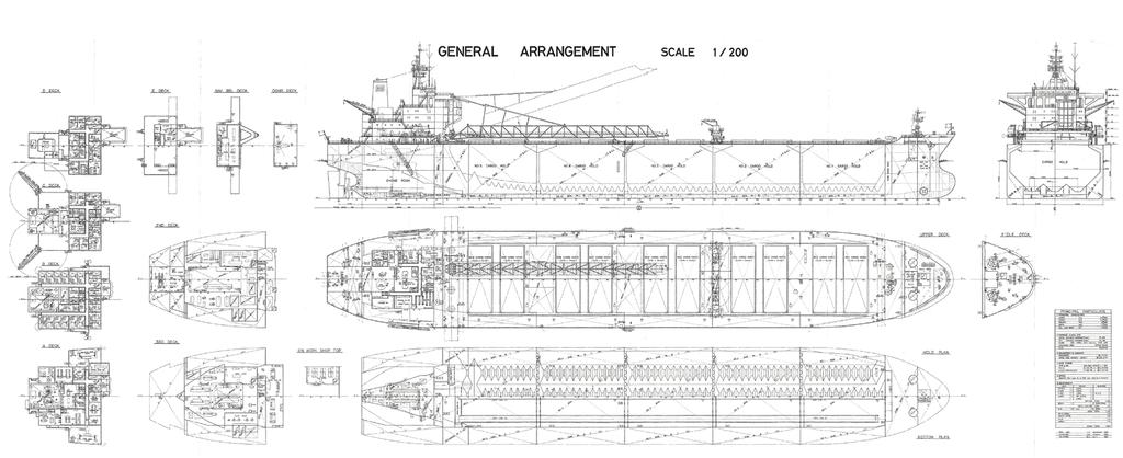
6 2.9 Ship s-use chemicals Stowage Guidance and regulation Radiation issues Risk of exposure to radiation Regulations Housekeeping Fatigue 63 Section 3 - CONCLUSIONS Safety issues directly contributing to the accident which have resulted in recommendations Other safety issues identified during the investigation also leading to recommendations Safety issues identified during the investigation which have not resulted in recommendations but have been addressed 65 Section 4 - action taken The Marine Accident Investigation Branch V.Ships UK Limited Western Bridge (Shipping) Limited and Aggregate Industries UK Limited 66 Section 5 - recommendations 68 Figures and annexes Figure 1 Figure 2 Figure 3 Figure 4 Figure 5 Figure 6 Figure 7 Figure 8 Figure 9 Figure 10 General arrangement drawing showing key features relating to the accident Composite of photographs showing discharge hopper damage and wear to the Hardox and ceramic sacrificial protection tiles Position of temporary workbench used for hotwork Door between the engine room workshop and the SUS hydraulic pump space Schematic of the area of the hopper work Area in which the fire was discovered Fire-fighting on the tower Additional fire support from Glensanda Quarry s fire team Fireball erupting from the SUS tower Fire spread onto the conveyor boom
7 Figure 11 Figure 12 Figure 13 Figure 14 Figure 15 Figure 16 Figure 17 Figure 18 Figure 19 Figure 20 Figure 21 Figure 22 Figure 23 Figure 24 Figure 25 Figure 26 Figure 27 Figure 28 Figure 29 Figure 30 Figure 31 Figure 32 Figure 33 Figure 34 Figure 35 Steering gear compartment explosion Fuel tanks flaring off Extent of damage to tunnel conveyor belts Example of distortion in the SUS tower Engine room/sus hydraulic pump space door Exposed steering gear compartment View of poop deck relocated to the funnel deck Schematic of the SUS showing conveyor belt drives Vertical conveyor belt arrangement Internal view of the hopper trouser leg showing sacrificial Hardox and ceramic tiles Yeoman Bontrup - starboard silometer source container Yeoman Bontrup - port silometer source container Yeoman Bridge - port silometer source container Doubler plates fitted to the outside of the hopper carcass Hopper carcass penetrations Oxy-acetylene torch cutting attachment Oxy-acetylene torch shank Water ballast tank valves hydraulic power pack Water ballast tank valves hydraulic distribution lines 500W halogen lamp fitted to Yeoman Bridge Structural general arrangement, complete with the conveyor belt configuration Fire Tests stud and nut placed in cleat adjacent to the side curtain Fire Tests stud and nut placed in cleat adjacent to the side curtain after 10 minutes Elongation of hopper carcass Hardox tile securing stud holes Flame cut bolts similar to those used to secure the Hardox tiles
8 Annexes Annex A Hotwork request No 15/10 for SUS hopper repair, dated 2 July 2010 and associated Safety Action Plan and risk assessment Annex B Hotwork request No 16/10 for No 4 WBT repair, dated 2 July 2010 Annex C Annex D Annex E Annex F Silometer handbook Safety Instructions, Safety Instructions for Operation and Endress + Hauser Service Report dated 18 March 2002 Castrol Hyspin AWH-M15 material safety data sheet VMS Self-unloading Section Sections Prevention of Conveyor Belt Fires and Dealing with Conveyor Belt Fires VMS Section Hotwork Annex G Yeoman Bontrup Chemical Inventory June 2010 Annex H Yeoman Bontrup chemical stowage arrangements June 2010 Annex I Annex J VMS Section Working with Dangerous or Hazardous Materials and Goods VMS (Ship Safety Training and Record Book) Section 8.3Onboard Drills Annex K Buildings Research Establishment Fire Test report No dated 15 November executive summary, summary of principal outputs of the cone calorimetry tests and conclusions Annex L Annex M Annex N Annex O Annex P Extracts from Hawkins & Associates Ltd s Fire Investigation Report C69/45210 dated 2 September 2010 Extracts from Hawkins & Associates Ltd s report on Ignition of Hydraulic Oils by Hot Surfaces C69/45210 dated 10 November 2010 MAIB Safety Flyer New VMS Section Exposure to Radiation Sources On Board Amended risk assessment for hopper repair work Annex Q Amended drill schedule including SUS space fire drills Revision 3
9 GLOSSARY OF ABBREVIATIONS, ACRONYMS AND TERMS AB - Able-bodied seaman BA - breathing apparatus BRE - Buildings Research Establishment CCR - Cargo Control Room CG - Coastguard CO 2 - carbon dioxide CSL - Canada Steamship Lines DfT - Department for Transport DIN - Deutsches Institut für Normung DPA - Designated Person Ashore ECR - Engine Control Room EN ISO - European Norm International Standards Organization ETV - Emergency Towing Vessel GRP - glass reinforced plastic HIFRS - Highlands and Islands Fire and Rescue Service HRR - Heat Release Rate ISM Code - International Safety Management Code kg - kilogram kw - kilowatt m - metre MAHRE - Maximum Average Heat Release Emission MCA - Maritime and Coastguard Agency MIRG - Marine Incident Response Group mm - millimetre
10 MSDS - Material Safety Data Sheet MS&Q - Marine, Safety and Quality PPO - Primary Productions Operations SMS - Safety Management System SOLAS - International Convention for the Safety of Life at Sea, 1974 SUL - Self-unloading SUS - Self-unloading System TSSR - Technical Superintendent Structural Repairs UHMW - Ultra high molecular weight UNC - Unified Course VHF - Very High Frequency VMS - V.Ships Management System W - watt WBT - water ballast tank Class A-0 bulkhead A bulkhead constructed of stiffened steel or equivalent which prevents the passage of smoke and flame but is not required to satisfy heat transfer criteria Class A-60 bulkhead An insulated bulkhead constructed of stiffened steel or equivalent whose unexposed side will not rise more than 140ºC, or at a single point more than 180ºC, above the original temperature for a minimum of 60 minutes Closed cup flashpoint A method of measuring the flashpoint of a liquid using a covered container through which an ignition source is passed to ignite vapours given off from the heated liquid Deutsches Institut für Normung German Institute for Standardization
11 Gold Command Half-life Hardox Hotwork Silver Command Tool-box talk Tunnel men The strategic level of the command and control structure used by the emergency services to deal with major incidents and emergencies The amount of time it takes for half of the atoms in a radioactive sample to decay A hard, wear-resistant steel plate used to provide protection in highly abrasive environments such as in the quarrying, construction and recycling industries Work that involves burning, welding, grinding or flame-cutting resulting in the potential for an incendiary spark The tactical level of the command and control structure used by the emergency services to deal with major incidents and emergencies A briefing given on the procedures and precautions to be taken to those carrying out a specific task Crew members whose role was to monitor cargo unloading from the cargo holds to conveyor belts Times: All times used in this report are UTC+1 unless otherwise stated

12 Image courtesy of FotoFlite Yeoman Bontrup

13 SYNOPSIS On 2 July 2010, a major fire and explosion occurred on board the Bahamian- registered, self-unloading (SUL) bulk carrier Yeoman Bontrup during cargo loading. The fire spread rapidly, resulting in significant damage to the vessel. Fortunately, injuries were minor. A routine post-discharge survey identified the need for repairs to Yeoman Bontrup s cargo discharge hopper, which required hotwork on arrival at the remote Glensanda Quarry on Loch Linnhe. At 1519, a fire was discovered near the bottom of the vertical cargo conveyor belt. Although attempts were made to extinguish the fire, it spread to the adjacent engine room. Overwhelmed by the scale of the fire, the crew evacuated the ship. The fire spread rapidly to the accommodation and into the steering gear compartment, which contained a wide variety of ship s-use chemicals. A violent explosion followed which tore the poop deck from the ship. The most likely cause of the fire was the ignition of the vertical conveyor belt by hot debris from the hopper repair work. Although the vessel was built to the required standards, the fire spread quickly. This was because there was no effective means of early detection, no means of dividing the large cargo handling area for containment purposes, and no fixed fire-fighting system in the cargo handling area to deal with the fire. The investigation found that the high frequency, and therefore routine nature of hotwork repairs on board Yeoman Bontrup had led to violations of company procedures, which compromised safety. Furthermore, elements of the conveyor belt were highly flammable. There are currently no conveyor belt material standards specific to the marine industry. The investigation also discovered radioactive silometers in the area of the fire. These had not been included in the list of hazardous materials on board, had not been identified during risk assessments, and were not subject to any control procedures. The ship s manager has taken action to improve hotwork procedures compliance and risk assessment, revise ship s-use chemical stowage arrangements and widen the scope of emergency drills. The ship s owner has established an SUL Owners and Operators Forum to review safety issues relating to the industry sector. Recommendations have been made which are designed to: Review and improve standards for fire detection, containment and extinguishing in the cargo handling areas of self-unloading vessels as well as develop standards for conveyor belt systems. Establish international standards for the use and control of radioactive isotopes on ships. Review national guidance on ship s-use chemical stowage. Address complacency with respect to hotwork procedures. 1
14 Section 1 - FACTUAL INFORMATION 1.1 Particulars of Yeoman Bontrup and accident Vessel details Registered owner : Western Bridge (Shipping) Limited Vessel operator : Aggregate Industries UK Ltd Manager : V.Ships UK Ltd Flag & port of registry : Bahamas, Nassau Type : Bulk carrier self-unloading (SUL) Date built and builder : 1991, Tsuneishi Shipbuilding Co Japan IMO number : Classification society : Lloyd s Register Construction : High tensile steel Length overall, breadth : 249.9m, 38m Gross tonnage : Engine type, power and propulsion : Single, 6 cylinder MAN-B&W 6S70MC, 2 stroke engine. Output 15402kW, service speed of 15 knots. Single fixed blade propeller, 1800kW bow thruster and 1500kW stern thruster. Accident details Category : Very serious marine casualty Time and date : 1519 on 2 July 2010 Location of incident : 56º 34.1 N 005º 31.9 W, alongside the shiploader jetty at Glensanda Quarry on Loch Linnhe, Western Scotland Persons on board : 31 crew, one superintendent and three visitors Injuries : Two cases of minor smoke inhalation, one of which also suffered bruising Damage : Significant fire damage and severe distortion to: the self-unloading system; engine room; accommodation areas; and steering gear compartment. Detachment of the poop deck. 2
15 1.2 Background Vessel overview Yeoman Bontrup and her sister ship Yeoman Bridge were the world s largest gravity fed self-unloading (SUL) bulk carriers. The ships were fitted with five cargo holds, totalling m 3. A complex system of conveyor belts discharged cargo into a hopper, situated in a tower immediately forward of the accommodation block and bridge. The cargo then passed onto a boom conveyor for shore reception. Both ships were built partly from high tensile steel, which had suffered extensive cracking, requiring long-term management with the agreement of Lloyd s Register, the ships classification society. At the time of the accident the owner s Technical Superintendent Structural Repairs (TSSR) was on board to carry out structural surveys and oversee structural repairs. A general arrangement drawing of Yeoman Bontrup, with highlighted key areas relating to the accident, is at Figure 1. The ship was manned by 31 Ukrainian crew, most of whom had served with the company for many years. The manning level was well in excess of the 14 crew required by the Safe Manning Certificate. The official working language was English, but the day-to-day language spoken was Russian. The documentation was in English Operation and commercial background Yeoman Bontrup, Yeoman Bridge and another self-unloader, Yeoman Bank, were operated by Foster Yeoman Limited which was part of the Aggregate Industries UK Ltd group whose shipping operations department was based in Frome, Somerset. Both Yeoman Bridge and Yeoman Bontrup were built to a British Steel specification for carrying iron ore to supply its steel plants. Following British Steel s takeover, Corus Group used the ships until October 2000 and September 2002 respectively, when they were sold to Aggregate Industries (UK) Limited. Since then, the vessels had been used to transport stone cargoes, predominantly various grades of granite. Yeoman Bontrup traded on a mainly circular route. Cargoes were loaded at Aggregate Industries (UK) Limited s Glensanda Quarry on Loch Linnhe in Scotland and Bremanger Quarry at Svelgen in Norway. The cargoes were self-unloaded at North European ports, notably in Holland, Germany, Belgium and France, and at the Isle of Grain in the UK. Glasgow-based V.Ships UK Ltd had been the ships manager since September The crew were contracted through V.Ships manning agency in Odessa, Ukraine. 3
16


17 1.3 Narrative Events leading up to the arrival at Glensanda Quarry Yeoman Bontrup arrived at Rotterdam at 1905 on 26 June 2010 to fully selfdischarge a cargo of tonnes of crushed sandstone she had loaded at Bremanger Quarry. During the time alongside, following approval by the ship s manager, hotwork was carried out to repair structural cracking in No 2 water ballast tank (WBT). Cargo operations were completed at 1850 on 29 June. The vessel sailed for Glensanda Quarry, in ballast, at 1905, and soon afterwards the self-unloading system (SUS) was washed down in preparation for its routine post-discharge inspection, which was planned for the following afternoon. The inspection by the chief engineer and cargo engineer identified a small number of familiar defects associated with the SUS conveyor belts. It also identified that about 40 Hardox and 30 ceramic sacrificial tiles, fitted to the inside of the cargo discharge hopper, had been badly abraded or were missing. It was also found that the mild steel carcass of the discharge hopper had been holed in a number of places (Figure 2) by the hard sandstone cargo during the discharge operation. At 0807 on 1 July, the findings were reported, by , to the ship s manager and to the operator s technical manager. Figure 2 Hardox tiles ceramic tile 4 Composite of photographs showing discharge hopper damage and wear to the Hardox and ceramic sacrificial protection tiles
18 Later that day, the cargo engineer met with the chief engineer to agree the scope of the SUS repairs. Preparatory work was also carried out that involved cleaning the hopper s defective areas and assembling the repair materials. As a limited number of Hardox and ceramic tiles were available on board to effect the repairs, it was decided to use a number of Hardox plates to cover the larger holes. The plates were cut to shape using oxy-acetylene equipment at a temporary work bench located on the main deck at the port side of the vertical conveyor tower (Figure 3) Arrival at Glensanda Quarry to the start of hopper hotwork Yeoman Bontrup arrived at Glensanda Quarry at 2135 on 1 July. Soon afterwards the bolted, hinged door 1 in the engine room workshop s forward bulkhead was opened into the SUS hydraulic pump space (Figure 4). This was normal practice in harbour and provided easy access between the tower and hold tunnels, and the workshop. Soon afterwards, the chief engineer and the chief officer agreed the risk assessments for the hotwork repairs to the SUS hopper and for No 4 WBT, which had suffered structural cracking. At 2230, de-ballasting was started as a cargo of seven grades of granite stones was being loaded. During the early morning of 2 July, the chief engineer discussed the proposed routine hotwork repairs with the master, who agreed the repairs were necessary. At 0618, hotwork request No 15/10 (Annex A), together with the associated safety action plan and risk assessment, was sent to the ship s manager by . At 0753 a further hotwork request, No 16/10 (Annex B), together with the supporting documentation was submitted for work in No 4 WBT. However, unbeknown to the ship s team, this request remained in the onboard computer s outbox and was not despatched to the ship s manager because of connectivity difficulties. At 0700, the chief engineer carried out a tool-box talk with the cargo engineer and the two tunnel men who were to carry out the hopper repairs. The repair team rigged a fire hose from the pressurised fire main to deal with any potential fires resulting from the intended hotwork. Protective fire blankets were laid on the boom conveyor belt and on a plywood sheet covering the return section of the vertical conveyor belt which passed between the hopper legs. Electric arc welding leads were led from the welding machine, located in the starboard deck workshop, into the hopper chute. Oxy-acetylene hoses were run to the chute area from a portable bottle trolley positioned on the main deck to the starboard side of the conveyor tower, and an oxy-acetylene cutting attachment was also taken into the chute. A schematic of the area of the hopper work is at Figure 5. 1 Although the access was a bolted, hinged plate, Lloyd s Register defined it as a door at build, hence the term door is used throughout this report. 5
19 At 0739, the ship s Designated Person Ashore (DPA), who was also the ship s manager s Senior Marine, Safety and Quality (MS&Q) Superintendent, ed his approval for the hopper repairs; hotwork request No 15/10. Position of temporary workbench used for hotwork Figure 3 6

20 Figure 4 Door between the engine room workshop and the SUS hydraulic pump space 7
21 Figure 5 Approximate to scale: 1.9m Radioactive source containers Area of Hot work 2 tunnel men inside chute Silometer detector Cargo Engineer inside lift tower (belt side) Return belt fire blanket Cargo discharge Boom conveyor fire blanket Boom conveyor Loaded lift belt-up Engine room (Top plates level) Engine room workshop access door Hydraulic pump room Empty lift belt-down Power pack level X conveyor feed Tank tops Schematic of the area of the hopper work 8
22 1.3.3 Hopper repair work At 0900, the chief engineer, who was the designated repair supervising officer, advised the hopper working party that hotwork request No 15/10 had been approved. He and the chief officer, who was the task-designated safety officer, met with the cargo engineer, who was in charge of the repair, in the conveyor tower to review the safety precautions that had been taken. Satisfied with the measures, the chief engineer endorsed the hotwork permit. The chief engineer and second engineer, who was also the on-watch engineer, then started the planned maintenance of the main engine exhaust valves. Meanwhile, the third engineer was in the engine room workshop carrying out a pump overhaul. During the morning, the damaged Hardox and ceramic tiles were removed from the hopper. It was reported that the team used a pneumatic socket to remove the captive nuts from the Hardox tile studs and a pneumatic chisel for use on the ceramic tiles. At 1100 (1200 ship s time), work was suspended for a 1-hour lunch break. At 1200, the hopper repair work continued. The replacement Hardox tiles were held in position by a stud which passed through the hopper side and was fastened using a nut on the outside of the chute. The tiles were then secured together using 25mm-long tack welds. Throughout the repair, the cargo engineer kept the two fire blankets wet to guard against the risk of a fire developing from hotwork residues. At the same time, hotwork repairs were started to address the structural cracks in No 4 WBT, despite there being no approval received from the ship s manager for the work. The welders in No 4 WBT were equipped with a VHF radio and they took their electric arc welding supplies from a control panel positioned approximately mid-way down the central tunnel. The repair was undertaken with the TSSR in attendance, who monitored and assessed the quality of the repair. The hopper-related hotwork was suspended at 1400, at which time the afternoon break was taken. Contrary to the requirements set out in the safety action plan (Annex A), a continuous fire watch was not maintained during the break period. By this time, the chief engineer had visited the site 2-3 times and had detected nothing to raise his concerns Events leading up to the discovery of the fire The hopper repair work recommenced at about with the fitting of Hardox plates to cover the largest holes. Shortly afterwards, the chief officer instructed an able-bodied seaman (AB) to remove the lid of No 3 WBT so that he could show the TSSR some structural cracks, which he had found during a routine WBT survey. 9
, contacted the TSSR to discuss and examine the cracks in No 3 WBT.")
23 The repair to No 4 WBT was completed at The two welders involved waited in the tank for the TSSR to confirm that the repairs were satisfactory. At about the same time, the chief officer, who was in the Cargo Control Room (CCR), contacted the TSSR to discuss and examine the cracks in No 3 WBT. He also started the boom conveyor hydraulic slewing pump, to warm it up in readiness to move the boom inboard to reduce the ship s list caused by cargo loading. At approximately 1516, the AB sent to open No 3 WBT lid took the elevator down to the engine room workshop. From there he went through into the SUS hydraulic pump space, leaving the dividing door open. He then made his way down the ladders towards the bottom of the SUS tower. At about 1518, the two welders in the SUS hopper noticed a slight wisp of smoke coming into the hopper, and warned the cargo engineer. At 1519, the AB reached the lower platform of the vertical conveyor belt. He smelt smoke and, as he turned slightly, he saw a great deal of smoke developing and about 1.5m 2 of flame around the rising part of the vertical belt adjacent to the forward engine room bulkhead (Figure 6). Figure 6 Location of fire above and behind this point 10 Area in which the fire was discovered
24 1.3.5 Actions following discovery of the fire The AB who discovered the fire was not equipped with a radio, so he ran back up the ladders to the CCR to alert the chief officer to the fire. On passing through the SUS hydraulic pump space, he shouted to the third engineer that there was a fire. The third engineer entered the hydraulic pump space, and on seeing large amounts of grey smoke he returned to the engine room to alert the chief and second engineers, who immediately started the three remaining fire pumps. At about this time a number of concurrent observations were made and actions taken. The welders in the hopper made their escape down the chute onto the boom conveyor and then onto the upper deck. Once there, they met with the cargo engineer who was already directing a fire hose into the tower s starboard doorway. The master, who was in his office with the quarry s administration manager and two of his staff, saw smoke outside the window. As he ran to the bridge, he told the visitors to remain in the office, which overlooked the upper deck. The manager noticed that the smoke from the tower was increasing and took his staff to the gangway, where they left the ship. The manager then remained on board and contacted a number of key quarry personnel, including the harbourmaster, to alert them to the fire. By this time the TSSR had taken the elevator, which was clear of smoke, to the main deck to meet with the chief officer. On exiting the port cross alleyway onto the main deck he noticed the dense smoke from the tower. At 1521, the ship s fire alarm sounded. It is unclear whether this was as a result of one of the tower s heat detectors activating, or either the second engineer or chief officer pressing a fire alarm button. As the master reached the bridge, he confirmed that the three remaining fire pumps were running, pressed the muster station alarm and made a broadcast advising the crew of the fire. He also contacted the Glensanda Quarry harbourmaster requesting fire-fighting assistance. The harbourmaster, in turn, advised Clyde Coastguard (CG), who alerted the Highlands and Islands Fire and Rescue Service (HIFRS) and the ambulance service. The master then advised the DPA of the situation. On the upper deck, the cargo engineer was relieved by a crew member who continued to direct the fire hose into the tower. Immediately afterwards, at 1524, a number of additional hoses were directed at the tower (Figure 7). The cargo engineer activated the tower wash-down sprays from inside the SUS hydraulic pump space in an attempt to help douse the fire. He then went to the base of the tower, where he rigged a fire-fighting hose and directed it at the fire. By now, the chief engineer had taken the elevator, which was clear of smoke, from the engine room to the upper deck. Believing the fire might have been due to the hopper hotwork, he ran up to B deck level. There, he became affected by the smoke so he returned to the upper deck and went to his muster station. 11

25 Figure 7 Fire-fighting on the tower After the AB informed the chief officer of the fire, the chief officer told the quarry staff to stop loading the cargo. He then made a general announcement about the fire on his VHF radio. The AB then ran back down the tower ladders, where he was joined by the second and third engineers, who discharged two foam extinguishers at the fire with no effect. The engineers, having heard the muster station alarm, opted to return to the Engine Control Room (ECR) through the SUS hydraulic room access, which was still open. They then went to their muster station. At the same time, the AB continued down to the lower level of the tower and joined the cargo engineer in fighting the fire. By this time, the fire had travelled quickly up the vertical conveyor belt despite the best efforts of the cargo engineer. The cargo engineer, feeling the effects of the smoke inhalation he had suffered during his descent from the SUS hydraulic pump space, stumbled, fell onto the deck plates and bruised his ribs. However, the two welders from No 4 WBT joined him and the AB in tackling the fire using the tunnel fire hoses and the cargo engineer recovered sufficiently to assist with the fire-fighting. 12
26 At about 1527, the cargo engineer was noted to be unaccounted for at muster stations. With the agreement of the chief officer, the chief engineer went down the tunnel access space, which was forward of No 1 hold, well away from the seat of the fire. On his way there, he started the emergency fire pump. On reaching about frame 75, in the central tunnel, he could see the area of the fire and also that fire hoses were being directed at it. He also saw that the cargo engineer was with the firefighters, and reported this to the chief officer. He saw that the area, a short distance forward of the fire, where the firefighters were positioned, was relatively clear of smoke. He also noted a slight airflow as air was being drawn through the open tunnel access door and ventilators, along the tunnels and up the tower in a chimney effect, dragging the smoke with it Consolidation Following the call to muster stations, the ship s fire organisation reacted to what was obviously a significant fire. The second engineer returned to the ECR, closing a number of engine room vents on his way there. Once back in the ECR, he stopped the fuel transfer pumps and made a number of electrical isolations, including those to the SUS hydraulic pump space, but he left power connected to the fire pumps. The third engineer also returned to the ECR, where he made sure the four fire pumps were running before rigging hoses in the vicinity of the engine room forward bulkhead. There was a conscious decision by the second engineer not to operate the emergency fuel shut-off valves from the fire control station because the generators were needed to provide power to the fire pumps. At 1533, the Glensanda Quarry fire team arrived with its tender under the direction of the Primary Production Operations (PPO) manager, who was also the senior site manager. The team connected its fire hoses to the shore-side hydrants and supported the boundary cooling effort around the tower (Figure 8). By about 1535, a high expansion foam generator had been rigged and was discharging foam into the tower through the main deck starboard door. A 2-man breathing apparatus (BA) team, comprising an AB and the tunnel man, were dressed and equipped with two BA sets from the fire control room and a spare BA set from the forward hydraulic pump room for rescue purposes 2. They were unable to enter the tower from the main deck because of the dense smoke levels. The 2-man BA team, accompanied by the bosun and the head tunnel man, entered the steering gear compartment and then the engine room. They were met by the second and third engineers, who were setting up boundary cooling on the forward bulkhead, which was adjacent to the fire. The engine room was becoming very smoky and hot in the vicinity of the forward bulkhead when, at about 1540, the 2-man BA team entered the open SUS hydraulic pump space door access. Once in the pump space, the team became separated in the dense smoke. The AB of the team managed to reach the lower level of the 2 The 4 th BA set on board was located in the Officer s Changing Room on D deck and could not be accessed because of the smoke levels. 13

27 tower, where he joined the other four crew members who were fighting the fire under the direction of the chief engineer. Fortunately, the other member of the 2-man BA team managed to return through the engine room workshop into the engine room; crucially, the door to the hydraulic pump space had been left open. It was at about this time that the second engineer noticed that the paint on the forward engine room bulkhead, on 3 rd deck level, adjacent to the tower and to starboard of the elevator, was blistering. He discharged a nearby CO 2 extinguisher onto the area, but with minimal effect. It was clear that the situation was deteriorating rapidly; the smoke levels were increasing in the engine room making further occupancy untenable. The third engineer contacted the master, who by that time had evacuated from the bridge onto the starboard bridge wing, and advised him of the situation by VHF. The master immediately instructed that the engine room be evacuated, and the team made their way safely back to the upper deck. At 1545, the Glensanda Quarry harbourmaster arranged for the company s landing barge and personnel boat to go to Rhugh Garbh, 9 miles from the quarry, to collect the HIFRS fire-tenders and firefighters as there was no road access to the remote quarry site. He also arranged for another personnel boat to go to Point Appin, about 4.5 miles away, to transport the HIFRS on-scene-commander (Silver Command) to the quarry. Figure 8 Additional fire support from Glensanda Quarry s fire team 14
28 The chief engineer and his team felt that they were achieving some success in dealing with the fire. However, they were not aware that by that time the SUS hydraulic pump space was engulfed in fire, and that the fire had spread into the engine room workshop through the open door. Despite the chief engineer s optimism, at about 1550 part of the conveyor belt collapsed. He reported this to the master, who was in discussion with the quarry s PPO manager. The quarry staff then noticed the portable oxy-acetylene bottle stowage that was used in support of the hopper repair work. Worried about the hoses which were led to the tower, and their close proximity to the fire, they moved the stowage away from the immediate danger, having confirmed that the bottle valves were closed 3. In doing so, one of them suffered the effects of smoke inhalation and had to be escorted off the vessel to await medical attention. At about , the Glensanda harbourmaster, in consultation with the quarry PPO manager and engineering manager, strongly advised the master to evacuate the ship. By then it was clear that the situation was getting out of control, with intermittent flames coming from the tower, despite the additional support from the quarry staff. No one was able to access the accommodation block, engine room or steering gear compartment, so the internal condition of the ship was unknown. With his crew still safe and accounted for, the master decided to abandon the vessel. He instructed the chief engineer to withdraw from the tunnel and return to the deck with his 5-man fire-fighting team. The chief engineer felt he could still make progress with the three fire hoses trained on the fire, and remained with his team fighting the fire until ordered to evacuate a few minutes later by the master. Once on deck, the bosun assisted the cargo engineer ashore for medical attention because he was still suffering from the effects of smoke inhalation and bruised ribs sustained earlier Pre-evacuation actions At about 1605, the master ordered the crew to leave the vessel once they had lashed their fire hoses to the ship s structure and directed them at the tower area to continue the boundary cooling effort. As the crew evacuated, the chief officer and chief engineer closed No 4 cargo hold hatch to help prevent any fire-fighting water from entering the holds and tunnels and impacting on the ship s stability. The mooring winches, which were in auto-tension, were set with their brakes on to prevent the vessel moving away from the berth after the inevitable loss of electrical and hydraulic power. The chief engineer tried to operate the engine room CO2 fire-extinguishing system, but was driven back by the heat and smoke. He did, however, manage to operate the diesel fuel service tanks emergency shut-off valves in the fire control station. The master, chief officer and chief engineer agreed they could do nothing more except to direct cooling water onto the ship from a safe distance on the quayside. Therefore, at about 1615 they left the ship. 3 It was unclear when and by whom the bottle valves were closed. 15
29 1.3.8 Post-evacuation actions The Glensanda Quarry personnel boat picked up the HIFRS (Silver Command) at Port Appin at It was clear from the briefing given to the Silver Commander that he had a major incident to deal with. At 1600, he contacted the HIFRS Incident Command at Inverness, which was set up to support Silver Command, and requested the expert advice of the HIFRS Marine Incident Response Group (MIRG). This was approved, and the CG set about making arrangements for the MIRG team to be transferred by helicopter from Invergordon. At 1630, the water supply to the hoses failed as the ship s generators stopped, either through lack of fuel, or because the fire caused interruptions to the electrical supplies. The Silver Commander arrived on scene at He considered that it was unsafe to access the ship, especially as there were 125 CO2, 14 large O2, 10 large acetylene and 5 small acetylene bottles in the vicinity of the fire. In addition, he was advised that there were 841 tonnes of intermediate fuel oil, 61 tonnes of diesel, 40 tonnes of lubricating oil and 2 tonnes of paint on board. He decided the only option at this point was to continue boundary cooling in an attempt to prevent the fire reaching these high-risk areas. However, as this could only be done on the starboard side, the Silver Commander requested the support of a fire-fighting tug so that the port side of the vessel could be cooled. As there were no suitable vessels available locally, the use of the Maritime and Coastguard Agency s (MCA) Emergency Towing Vessel (ETV) Anglian Sovereign was approved at At that time, the vessel was berthed at Stornaway and her estimated time of arrival was 0100 on 3 July. At 1700, a doctor arrived by the personnel boat with the first of the HIFRS firefighters. The fire team immediately set up its ground monitor fire hoses to continue the boundary cooling effort. At approximately 1715, a large fireball erupted from the top of the tower (Figure 9) and, about 10 minutes later, the gangway fell from the ship as the after mooring lines parted. The fire continued to develop and, by 1800, it had spread to the boom conveyor (Figure 10). The HIFRS tenders arrived at The HIFRS had just established a 200m exclusion zone when a massive explosion (Figure 11) tore off the entire poop deck, projecting it up into the air and landing it on the port side of the funnel deck. Soon afterwards, flames were seen coming from Yeoman Bontrup s stern area as the oils and chemicals stowed in the steering gear room, and the steering system s hydraulic oil charge, continued to burn. 16 At 2000, the HIFRS and Northern Constabulary Gold Command was established to support Silver Command. Links were established with the Highland Council Emergency Planning Officer, Scottish Ambulance Service and the Secretary of State s Representative in relation to salvage and counter pollution. A short time later, the 8-man MIRG team arrived on scene by helicopter. Still unable to access the vessel, the Silver Commander used MIRG s expertise to assess the situation and develop the tactical plan.


30 Figure 9 Fireball erupting from the SUS tower Figure 10 Fire spread onto the conveyor boom 17

31 Figure 11 Steering gear compartment explosion At about 2045, some of the crew managed to gain brief access to the ship to re-secure the after mooring lines. During this time it was noted that Yeoman Bontrup was trimming by the bow, and there was concern that she might touch the bottom and cause pollution. It was further suspected that back-flooding had occurred through the WBT stripping system that was in use when the fire was discovered. At 2232, it was agreed that two of the ship s engineers and four HIFRS firefighters should go on board to try to halt the progressive trim by the bow. They took with them a portable hydraulic hand pump to close the stripping pump valves as none of the ship s valves were fitted for manual operation. At about 2300, while they still were on board, the fuel oil and oil tanks began to flare off (Figure 12). The engineers managed to close the valve that had caused the back-flooding and left the ship at Now that the immediate danger was over and all personnel were safe and accounted for, Gold Command stood down in favour of multi-agency, on-site, briefings. 18

32 At 0055 on 3 July 2010, Anglian Sovereign arrived on scene and immediately began boundary cooling Yeoman Bontrup using her high-pressure, high-volume fire-fighting monitors. Cooling continued throughout the night and, at 0512, the MIRG team was stood down. Figure 12 Fuel tanks flaring off Salvage At 0855, both the HIFRS and Anglian Sovereign stopped boundary cooling to allow the fire to burn itself out and to facilitate the commercial salvage team s initial survey. At 1321, responsibility for the fire-fighting effort was transferred from the HIFRS to the salvage company. The salvage company recorded deck temperatures of over 200ºC in the accommodation area, and concluded that the engine room was too hot to enter. The next few days were spent extinguishing small pockets of fire, allowing the ship to cool down, and making her safe to tow. As soon as she was safe to tow, Yeoman Bontrup was towed away from Glensanda so she did not ground during the forthcoming spring tides, and she finally arrived at Ijmuiden in the Netherlands on 28 July for detailed damage survey to determine the repair options. 19
33 1.4 Glensanda Quarry General Glensanda Quarry is located on the remote western side of Loch Linnhe in Scotland. The site is inaccessible by road. The company s landing craft plies between the quarry and the company s mainland site at Rhugh Garbh, 9 miles away, where heavy machinery can be loaded. Four personnel boats operate between the quarry, Rhugh Garbh and Port Appin. There are also two mooring boats. None of the vessels had any fire-fighting resource capable of assisting a marine casualty. The site, which is the largest of its type in Europe, commenced operations to quarry granite from the Meall na Easaiche mountain in The initial rock crusher is underground with the final, or secondary crushing plant situated close to the single-ship jetty. Cargo is loaded onto ships using the shore-side conveyor Fire-fighting facilities Glensanda Quarry had a total of 32 trained firefighters, who were also qualified first-aiders. They were split across four shifts and included maintenance staff. Each team was led by either the shift manager or his deputy. The site s single, ex-strathclyde Fire and Rescue Service tender, was equipped with a range of fire-fighting equipment and a water capacity sufficient for 8 minutes fire-fighting. A fire main, pressurised at 11 bar, was fitted with hydrants and ran throughout the site, including the jetty area. The teams were used as first responders only, to enable casualty evacuation and containment. They received annual refresher training and carried out regular drills. They were not trained in ship fire-fighting techniques or in the use of BA and so all fire-fighting was intended to be carried out in fresh air. In the event of a marine emergency, the company had developed an emergency plan for the guidance of senior managers. This was the first marine incident that required quarry fire-fighting support in 25 years. 1.5 Environmental conditions The environmental conditions at Glensanda Quarry were recorded every 15 minutes at a weather station situated on the Shiploader Jetty. At 1515 on 2 July 2010, the wind was south-westerly (238º) force 4/5 (mean knots). It was overcast and the air temperature was 17.3ºC. Low water was at Overview of fire-related damage General With the exception of the bridge, which suffered fairly minor heat and smoke damage, virtually the whole of the after end of Yeoman Bontrup was extensively damaged in the fire and explosion. 20
, as were the two cross-conveyor belts.")
34 1.6.2 Self-Unloading System (SUS) The fire damage in the hold tunnels reached as far forward as frame 167 with the port, starboard and centre hold conveyor belts being consumed from this point aft (Figure 13), as were the two cross-conveyor belts. The distinct line of the limit of damage suggests that the three tunnel belts forward of this point were covered by water that had accumulated in the tunnel 4. All flammable material in the vertical conveyor belt tower and the SUS hydraulic pump space was completely destroyed, and there was massive structural distortion to the steel doors, ladders and bulkheads (Figure 14). Figure 13 Limit of fire damage Extent of damage to tunnel conveyor belts 4 The fire-fighting water level was deeper in the forward end of the tunnels due to the ship s increasing forward trim. 21
.")
35 Figure 14 Example of distortion in the SUS tower Engine room and adjacent compartments The engine room workshop contents were completely consumed as the fire passed through the open SUS hydraulic pump space door (Figure 15). The engine room forward bulkhead suffered distortion through heat transfer from the SUS tower. The fire consumed the ECR, electrical workshop and switchboard. The heat damage was especially severe at the upper levels of the engine room, which resulted in the overhead gantry falling to the lower level. The purifier room, situated on the starboard side, and the lower levels of the engine room escaped large-scale damage Steering gear compartment The numerous oil drums and chemical containers in the steering gear room were largely consumed by the fire or resultant explosion. There was nothing left of the racking used to secure these items, and the transom had been set aft by about 1 metre. There was massive over-pressure damage to fittings in the compartment and to the rope store. The poop deck was torn off, leaving the steering gear exposed (Figure 16). The deck areas above the port and starboard fresh water and after peak tanks suffered severe buckling and distress, and the plating at the after engine room bulkhead had split and had been torn upwards. The poop deck itself had landed on the funnel deck, complete with its winches and mooring equipment (Figure 17). 22


36 Figure 15 Engine room/sus hydraulic pump space door Figure 16 Exposed steering gear compartment 23

37 Figure 17 Poop deck Transom set back by approximately 1m View of poop deck relocated to the funnel deck Other areas All compartments on the upper deck and in the accommodation block, including the store rooms, paint store, workshops, fire control room, cabins, galley and offices, were consumed by the fire, and many suffered severe structural distortion. The upper deck in way of the after hold and the after hold transverse stiffeners were severely distorted. 1.7 Self-Unloading System General description and regulation The SUS was designed and manufactured by Consilium BMH Marine of Enkoping, Sweden to handle stone cargoes of up to 150mm in diameter. The system was controlled from the CCR. A schematic of the SUS, including the layout of the conveyor belts and types of drive, is at Figure 18. The International Convention for the Safety of Life at Sea 1974 (SOLAS), does not contain regulations covering the SUS equipment or conveyor belt requirements, and the system is not covered by classification society rules. 24
38 Figure Hydraulic drive Electric motor drive Hopper Trouser legs A Path of vertical conveyor belt A Chute Vertical conveyor belt 2 Boom conveyor 2 Port cross conveyor Port side of hold Spillage chute 1 Port tunnel conveyor A Centre section of hold 1 Centre tunnel conveyor 2 1 Starboard cross conveyor Starboard tunnel conveyor Starboard side of hold Schematic of the SUS showing conveyor belt drives Holds Each of the five holds was designed with a number of tapered sections that directed the cargo through hydraulically-operated basket gates onto one of three longitudinal hold conveyor belts. Each of the 181 gates was fitted with a hydraulically-operated vibrator to loosen the cargo in the event of hold-ups. To assist the gravity feed onto the belts, the holds were lined with Ultra High Molecular Weight (UHMW) polyethylene sheeting, which improved the flow characteristics of the cargo. 25
39 1.7.3 Hold conveyor belts There were three hold conveyor belts identified as port, centre and starboard. Each was of a trough profile, 2.2m wide and 170m long, and was supported by a series of rollers against each of the outer faces of the trough. Each conveyor belt discharged cargo onto its respective cross-conveyor. In an emergency, the belts could be stopped by pulling on the emergency stop wire, which stretched the length of each tunnel. The belts were driven by an hydraulic motor positioned at the after end of the tunnel Cross-conveyors There were two cross-conveyor belts positioned at right-angles to the hold conveyor belts. The port belt received cargo from the port hold conveyor belt and the starboard belt received cargo from both the centre and starboard hold conveyor belts. Each of the two belts discharged onto the vertical lift conveyor belt while it was in its horizontal plane. Each of the cross-conveyor belts was driven by an electric motor positioned at the outboard end of each belt Vertical conveyor belt The vertical conveyor arrangement is shown at Figure 19. The conveyor belt, which was purchased by the previous owners in 2000, had a life-expectancy of about 10 years. This was determined by the number of fatigue related rotations. The base belt was 2.4m wide and strengthened by a matrix of zinc-coated steel wires. It was fitted with pockets, known as cleats, at 500mm intervals for carrying the cargo. Each cleat was fitted with a renewable sacrificial facing. Corrugated soft rubber side curtains, 630mm high, were fitted to the sides of the belt to prevent cargo falling from the sides of the cleat. As the belt passed over the uppermost after idler pulley, the cleats inverted and discharged cargo into the top of the hopper. Any cargo spillage from the cleats was collected in the spillage chute, located near the base of the vertical belt, and directed back onto the belt. The base belt had been repaired by a specialist contractor using a recognised hot vulcanising procedure following a previous fire in November The side curtains were replaced in July 2009 after suffering cracking due to their fatigue life being exceeded. The belt was driven by an hydraulic motor positioned at E deck level in the SUS tower and was supported by seven idler pulleys and two guide rollers Discharge hopper The hopper directed the cargo through a chute and onto the boom conveyor for final discharge ashore. A short distance from the top, the hopper split into two outward angled legs known as trouser legs. These rejoined lower down to form the chute. The central diamond shaped section, created by the legs splitting and rejoining, formed the return path for the vertical conveyor belt. 26
40 Figure 19 Vertical conveyor belt arrangement 27

41 The internal surfaces of the hopper were protected by a combination of sacrificial Hardox and ceramic tiles. The ceramic tiles were secured to the hopper carcass using a special adhesive while the Hardox tiles were secured using a nut and bolt arrangement. Both tile types (Figure 20) required frequent replacement. In the case of the Hardox tiles, this involved flame-cutting hotwork to trim the tiles and tack welding to secure the new tiles to adjacent tiles. The internal apex created by the legs was protected by right-angled Hardox tiles. The angle formed filled with cargo and provided a flush face to assist the cargo discharge. The system was designed for discharge rates of up to 6000 tonnes/hour. Each cargo type had an optimum discharge rate, greater or lesser rates of discharge resulted in stones impacting on the more vulnerable side of the hopper, which then required more maintenance. Figure 20 Ceramic tiles Hardox tiles Internal view of the hopper trouser leg showing sacrificial Hardox and ceramic tiles Boom conveyor The 2m wide, 84m long boom conveyor belt was driven by two electric motors. Cargo on the belt was protected by a glass reinforced plastic (GRP) cover. The boom could be slewed out through a range of 180º using an hydraulic pump located on the upper deck. Boom-luffing hydraulic power was provided by No 2 power pack located in the SUS hydraulic pump room. 28
42 1.8 Silometers General description Cargo in the hopper of both Yeoman Bontrup and Yeoman Bridge was originally monitored by two radioactive silometers. They were designed to identify cargo blockages in the hopper and stop the SUS in a controlled manner to prevent damage. The silometers comprised a radiation source, a detector (Figure 5), and an electronic process controller. While the system had not been in operation for the past 10 years, the silometers had remained on board. The two QG100 radioactive source containers were manufactured by the Swiss company Endress + Hauser. The units were mounted at D deck level, on a bracket, close to the after side of the hopper s trouser legs. Each unit weighed approximately 87kg and was fitted with a cobalt 60 radioactive source. The source had a half-life of 5.3 years and was surrounded by lead encased in steel, which screened the emitted gamma rays. The container was designed to accept a padlock to secure the operating handle to prevent inadvertent operation Operation After the safety padlock was removed, a lever was turned through 180º which opened an internal shutter arrangement, allowing uni-directional measuring gamma radiation to be emitted through a narrow ray path through the hopper carcass to the Silometer detector for processing by the electronic controller. The operating lever uncovered an indicator plate which clearly showed if the unit was in the on or off position V.Ships Management System (VMS) and manufacturer s safety instructions The QG100 radioactive sources were not recorded on the VMS Technical Form - TEC 22 - Inventory of Potentially Hazardous Materials in the Ship s Structure and Equipment. The form was part of the master s emergency contingency plan documentation that was used to brief personnel responding to an emergency about the shipborne material risks. The VMS itself did not include any safety or general information relating to the radioactive source containers. The silometer manufacturer s handbook contained both general Safety Instructions and Safety Instructions for Operation (Annex C). In particular, the Safety Instructions stated: Observe the applying rules and national/international regulations and Do not operate or store damaged or corroded devices. The Safety Instructions for Operation stated: In designated use, operated under the specific ambient and operation conditions, no inspection or servicing is required. 29
43 However, the instructions also identified that if a unit was subjected to vibration or mechanical impact, a number of checks should be made including: check regarding corrosion of housing, weld seams, outer parts of source insert, lock/padlock [sic] Survey The units fitted to Yeoman Bontrup were last inspected on 3 February The inspection report implied that there were defects to the system detectors, which could not be powered up, and so the repair investigation was stopped. There was no evidence that any wipe readings were taken to ascertain the radiation levels on the surface of the source or in the vicinity of the source. Yeoman Bridge was inspected on 18 March As a result of the wipe readings, the contractor recommended (Annex C) that: Access to the walkway be restricted and/or the source holders be fitted with guards to prevent persons being in the radiation path. The source be switched off if anyone is required to work in the hopper Condition of the source containers and warning signs on board Yeoman Bontrup The starboard container was found to be corroded but still secured to its bracket. It was not fitted with a security padlock (Figure 21), but the operating lever was found to be in the off position. MAIB inspectors found the port container on the floor grating near to its supporting bracket when they first accessed the SUS tower on 7 July. It was in particularly poor condition. It was heavily corroded, which had resulted in widespread destruction of the steel casing and the fire had apparently caused melting of the radioactive source lead shielding (Figure 22). The operating lever was also in the off position but there was no security padlock fitted. When MAIB inspectors carried out follow-up work with other specialists on 3 August, they found the source containers still in their post-fire positions. The containers were finally removed from Yeoman Bontrup on 19 August. Any radioactive warning signs that might have been affixed to the area access doors or to the source containers would have been destroyed in the fire Condition of the source containers and warning signs on board Yeoman Bridge On inspection, both source containers were fixed to their supporting brackets and there was clear evidence of a build-up of surface corrosion. Neither unit was fitted with a security padlock but both operating handles were in the off position (Figure 23). The source containers were removed from the vessel in Rotterdam on 29 January The access doors displayed radioactive warning signs, but there were none on the source containers.


44 Figure 21 Operating lever Yeoman Bontrup - starboard silometer source container Figure 22 Lifting eye Corrosion and perforation of the outer casing Operating lever Missing security padlock Yeoman Bontrup - port silometer source container 31

45 Figure 23 On/off position indicator 1.9 Post-fire observations of the hopper External Yeoman Bridge - port silometer source container External examination of the hopper found that many of the Hardox tile securing nuts were corroded, and there was a mixture of round flat washers and rectangular washers beneath the nuts. There was widespread evidence of mild steel doublers welded to the external surfaces of the carcass to cover holes probably caused by cargo abrasion (Figure 24). There were also numerous examples of elongated holes burnt through the carcass using oxy-acetylene equipment. Many of these had been covered by Hardox tiles. There were a number of open small holes on all parts of the legs and also a much larger, 100mm hole, at the after end of the port upper leg (Figure 25) Internal There was evidence of new Hardox tiles and temporary Hardox plates having been fitted in the apex area of the chute and to the port and starboard legs. There were sections of used welding rods and also new ones resting on the angular Hardox tiles. The remains of a pneumatic chisel were located at the port side of the apex. The cutting attachment of an oxy-acetylene torch was found resting on the Hardox tiles inside the hopper at about 2.5m from the chute opening, and the shank was found with hose connections still attached 5 at the tail end of the boom conveyor (Figures 26 and 27) Remains of oxygen and acetylene hoses were found on the upper deck in the vicinity of the starboard side of the tower.


46 Figure 24 Doubler plates fitted to the outside of the hopper carcass Figure 25 Hopper carcass penetrations 33


47 Figure 26 Oxy-acetylene torch cutting attachment Figure 27 Oxy-acetylene torch shank Hardox tile 34 Oxy-acetylene torch shank
48 1.10 Hardox tile replacement procedure Abraded tiles which had not been discharged with the cargo remained connected to their ½ inch Unified Course (UNC) securing studs. Once the securing nuts were removed from the stud, the tile, complete with its stud, was drawn through into the hopper for disposal. Oxy-acetylene equipment was available to flame-cut distorted studs to ease their removal. Tile securing tack welding was removed either with a pneumatic chisel or by using oxy-acetylene equipment. Replacement tiles 6 were offered up and cut to size using oxy-acetylene equipment. They were then drilled to take a bolt, and the hole was countersunk to allow the bolt head to sit below the surface of the tile. The countersunk recess was then filled with weld, the bolt then effectively acted as a stud. The tile was secured in place by the nut, and 25mm tack welds were used to secure it to adjacent tiles. Where studs did not align with the stud holes, the holes were elongated either by using oxy-acetylene burning equipment or by striking electric arc welding rods on the carcass Hydraulic systems There were four separate hydraulic systems, which were either in close proximity to the fire or were pressurised at the time the fire was discovered Shore-discharge boom slewing system The hydraulic pump and associated pipework supplying the shore discharge boom slewing ram were positioned on the port side of the upper deck near to the vertical conveyor belt tower. Although the system was pressurised when the fire was discovered, none of the pipework passed through the tower SUS hydraulic system The five SUS hydraulic power packs, located in the tower hydraulic pump space, were fully shut down at the time of the fire. Various hydraulic supplies passed in the general area of the vertical conveyor belt, including small bore pipes supplying the hold gates and vibrators. Castrol Hyspin AWN-M32 and Castrol Hyspin AWH-M68 were used in the systems. The Material Safety Data Sheets (MSDS) listed their closed-cup flashpoints as above 190ºC and 200ºC respectively, and an auto-ignition point as above 250ºC for both oils Forward and aft hydraulic winch power packs Both the forward and aft mooring winch hydraulic packs were pressurised at the time of the fire, with the mooring winches set to auto-tension. The forward hydraulic packs were positioned just aft of the forecastle and all pipework was remote from the fire. 6 There were two sizes of Hardox tiles measuring about 300mm x 150mm and 150mm x 150mm and weighing 20 and 10kg respectively. 35
49 The after packs were located in the steering gear compartment. The supply and return pipework for the port mooring winch, which was positioned adjacent to the tower, passed through the upper levels of the SUS hydraulic pump space. Castrol Hyspin AWH-100 was used in both the forward and aft systems. The MSDS listed the closed-cup flashpoint as above 200ºC and the auto-ignition point as above 250ºC Ballast system valves A number of water ballast butterfly valves were hydraulically-operated and remotely-controlled from the CCR. The associated self-contained hydraulic system power pack was located on the starboard side, adjacent to the forward bulkhead of the engine room (Figure 28). The unit comprised a pump, with a normal operating pressure of 60 bar, and associated valves. The 250-litre capacity header tank had an operating level of 160 litres. The system was fitted with a tank low-level alarm and shut-down arrangement, which operated when the tank level dropped to 140 litres. A low pressure alarm operated at 40 bar. An audible buzzer and red-light alarms were located in the CCR only, and were tested automatically when the unit was started. The hydraulic oil was delivered to the ballast valves through 20mm diameter copper pipes which were located in the general vicinity of the fire. The sections of pipes were connected by brazed cup and cone couplings (Figure 29). The system was pressurised at the time of the fire. The oil used in the system was Castrol Hyspin AWH-M15. The MSDS (Annex D) listed the closed-cup flashpoint as above 140ºC and the auto-ignition point as above 250ºC. During normal operation, the temperatures of the supply and return oil were 30ºC and 24ºC respectively SUS vertical conveyor belt specifications Fitted belt specification The SUS vertical conveyor belt, cleats and side curtains, known as a Flexowell conveyor, were originally manufactured by the Finnish company Metso at its factory in Moers, Germany. In early 2010, conveyor belt manufacturing at the site was taken over by Continental ContiTech on its acquisition of this arm of the Metso operation. The belt manufacturer offered various fire-resistant and self-extinguishing belt and component options in accordance with the appropriate European Norm- International Standards Organisation (EN ISO) or the Deutsches Institut für Normung (DIN). 36


50 Figure 28 Water ballast tank valves - hydraulic power pack Figure 29 Water ballast tank valves - hydraulic distribution lines 37
51 It is understood that the specification of the original belt, identified by the manufacturer as being the same as the one involved in the fire, was agreed between the owner and shipbuilding yard. The specification confirmed that no fire-resistant properties were required. The base belt, known as carbon black was oil-based and was made from natural and synthetic rubber. The cleats and side curtains included natural and synthetic butylene rubbers. Table 1 contains Continental ContiTech s interpretation of the alphanumeric data relating to the Type/Grade and Quality of the fitted arrangement. Component Type/Grade Type/Grade/Quality interpretation Base belt type XST 4500 X special i.e. marine use ST steel cord belt Newtons breaking strength in length direction per mm of belt width Base belt grade YF-L Y standard belt F-L Flexowell (trade name) Side curtain type F 400 ES F - Flexowell (trade name) height of curtain ES over 300mm high with rubber/fabric sandwich construction Side curtain quality YF-L Y standard side curtain F-L Flexowell (trade name) Cleat type TC-GS TC special profile G rubber/textile sandwich construction S profile mm height Cleat quality YF-C Y- standard cleat F-C - Flexowell cleat Table 1 - Interpretation of the fitted belt specification Spare vertical conveyor belt specification Aggregate Industries UK Ltd held an option to purchase a spare vertical conveyor belt belonging to Oldendorff Carriers, another self-unloading bulk carrier operator. The belt, side curtains and cleats were manufactured to the following specification which was presented in a different manner to that of the fitted belt: 2400mm wide, profile F 630 ES VT, pocket profile VSF 120Y at 500mm spacing. 7 Actual height of side curtain confirmed to be 630mm notwithstanding nomenclature Although the specification states the figure is 370, the manufacturer confirmed this was an error and the correct figure should be 360
52 Table 2 contains Continental ContiTech s interpretation of the belt s data. Component Type/Grade Type/Grade/Quality interpretation Base belt 2400mm The overall width of the base belt is 2.4m Side curtain F 630 ES VT Side curtain 630mm high Extra strong Flame resistant quality Cleat VSF 120Y 500mm spacing Cleat bases 120mm high in standard quality glued to the base belt Cleat pitch 500mm Table 2 - Interpretation of the spare belt specification 1.13 Fire detection, containment and extinguishing in the cargo handling spaces Detection The vertical conveyor belt tower was fitted with single-head heat detectors at D deck, A deck and 3 deck levels. The three detectors were factory-set at 57ºC to activate the alarm panels in the fire control room and on the bridge, as required by SOLAS Chapter II-2, Part C, Regulation 7, Paragraph 4. There were no heat or smoke detectors fitted in the conveyor belt tunnels. The detectors were not annotated on the fire control plan reviewed by Lloyd s Register s Gdansk office on 27 February Cargo unloading operations were monitored by the tunnel men and by the duty officer in the CCR using four camera displays. The cameras were directed at the conveyor belts and the images were played in real time. The system was not equipped with a recording facility Containment Each of the three, 179m long x 9.3m wide tunnel spaces under the holds met with the 37m high vertical conveyor belt tower, effectively making the cargo handling area one large compartment. The compartment was not fitted with any form of division to contain either a fire or flood Extinguishing arrangements Neither the tunnel spaces nor the tower were equipped with any fixed fire-fighting system. The tower itself was fitted with a fresh water dust suppression system, which was used during cargo discharge operations. 39

53 Fire hoses and nozzles were positioned throughout the tunnels and at the base of the tower Lighting The area around the after end of the tunnel, near the vertical and cross-conveyor belts, was lit by a mix of 300W and 500W tungsten halogen lights. Two 400W sodium lights, positioned between 2 and 3m from the vertical belt, lit the general area in which the fire was discovered. Other 20W fluorescent tube lights were also in the general area. The surface temperature of the 500W tungsten halogen light lenses (Figure 30) was 135ºC with the body of the light measuring 41ºC. The temperatures measured at 100mm and 500mm from the halogen lights, in the direction of the vertical conveyor belt, were 40ºC and 26ºC respectively. The halogen lights were positioned approximately 1.3m from the vertical belt and about 2.9m from the pressured hydraulic system operating the ballast tank valves (Section ) 9. Figure W halogen lamp fitted to Yeoman Bridge 40 9 This information was obtained from Yeoman Bridge because light fittings on board Yeoman Bontrup had been totally consumed in the fire.
54 1.15 Flammability of the conveyor belts The high risk of fires developing in the areas of the conveyor belts was clearly recognised in the VMS. In the Self-Unloader Vessel Operating Instructions, which is a supplement of the VMS, the following sections emphasised the importance of correct safe working practices in relation to the hazard: Section : Hotwork in the lift belt casing is extremely hazardous as hot material can lodge in the pockets. Section : adequate cover, and wetting of the belt when carrying out hotwork in its vicinity. Section 4.5.1: Protect the conveyor belts adequately before carrying out hotwork in the vicinity. Section 4.5.3:.Fire rounds are to be taken at least two and six hours after completion of any hotwork in the Loop and tunnel areas [sic]. Section Prevention of Conveyor Belt Fires, and Section Dealing with Conveyor Belt Fires, provide further guidance. The full sections are at Annex E. Section states: Fires in the Loop and Tunnel areas are very dangerous, as the conditions are conducive to its rapid spread. and NOTE: WHEN PERFORMING HOTWORK ON THE UNLOADING GEAR, A FIRE OR WASH-DOWN HOSE UNDER PRESSURE MUST BE AT THE WORKSITE WITH ONE MAN PRESENT AS A FIRE WATCHMAN ONLY. THE FIRE WATCH IS TO BE MAINTAINED DURING COFFEE AND MEAL BREAKS. THE FIREWATCH MUST BE MAINTAINED FOR 60 MINUTES AFTER HOTWORK IS COMPLETED [sic]. The last paragraph of the above instruction is also included in the safety action plan, in red font for emphasis. Section emphasised that smoke from conveyor belt fires is highly toxic and acrid, and that the tower acts as a high riser (chimney), encouraging the fire. 41

55 1.16 Structure in the vicinity of the fire The structural general arrangement of the aft end of Yeoman Bontrup, complete with the conveyor belt configuration, is shown at Figure 31. Figure 31 Hotwork site Vertical conveyor belt arrangement Access to engine room workshop Approximate position of fire Structural general arrangement, complete with the conveyor belt configuration 42
56 Bulkheads The fire integrity requirements for bulkheads fitted to cargo ships are laid out in SOLAS, Chapter II-2, Part C, Regulation 9, Table 9.5. The engine room was designated as a Category A Machinery Space, the conveyor cargo handling area as an Other Machinery Space and the personnel elevator fell under the Stairways designation. In accordance with the compartment designations, the engine room forward bulkhead was a class A-0 bulkhead. The personnel elevator shaft, which abutted the vertical conveyor belt casing, was a class A-60 bulkhead Engine room workshop/hydraulic pump space access door The existence of the 26-bolt door that provided access between the engine room workshop and the SUL hydraulic pump space was known to Lloyd s Register at build and the door was required to be watertight. However, at the owner s request, a bolted, hinged watertight door was fitted in lieu of a sliding one. In acceding to the request for the door to be hinged, Lloyd s Register required that a permanent notice be affixed to both sides of the door, stating: This cover is to be kept closed at all times at sea Although the door was insulated to an A-60 standard, Lloyd s Register had no record of this. There was no requirement for the higher standard as the door was fitted to an A-0 bulkhead Structural cracking Since build, Yeoman Bontrup s high tensile steel structure had suffered from frequent cracking, which required a far greater amount of repair hotwork to be carried out than on a comparable mild steel hull. The cracking problem was particularly prevalent in way of the WBTs. The owner and manager had agreed a continual survey and repair procedure with Lloyd s Register to cover WBT repairs, but not defects to the shell plating, which required Class surveyor oversight. To provide the necessary expertise, the TSSR rotated around the owner s three ships to carry out surveys and to monitor and assess the quality of the repairs undertaken by two coded 10 welders, who formed part of the crew, once the ship was alongside. Repairs were necessary up to about three times per month. A full register of the defects was scrutinised and signed periodically by the Class surveyor. The register was last reviewed in mid-2010 when all the WBT special surveys were completed, with only minor deficiencies noted. 10 Welder recognised by a classification society or similar professional body as competent to undertake work on behalf of that body. 43
57 1.18 Designated hotwork areas and procedures Designated hotwork areas 44 The hotwork procedures were covered comprehensively in VMS Section (Annex F). The section identified that the engine room workshop was the only designated space that hotwork involving welding, burning, naked flame, high temperature, arc or a continuous spark process could be carried out without requiring prior approval from the ship s manager. Welding and burning equipment was additionally stowed in the bosun s store, and in the deck store and workshop in both Yeoman Bontrup and Yeoman Bridge Procedures Hotwork procedures fell into two categories as defined by VMS 4.6.7: those that required prior approval from the superintendent, and those that did not. For the hotwork planned for 2 July 2010, prior approval was required. The procedure required a detailed risk assessment to be completed on VMS form SAF03, which was to be agreed at a safety meeting chaired by the master. The completed risk assessment and hotwork request were then forwarded to the MS&Q superintendent for approval. A safety action plan, which specified the requirements and precautions, was also forwarded. On receipt of the request the MS&Q superintendent was required to thoroughly review the risk assessment and discuss the requirement with the relevant technical superintendent to determine whether or not the hotwork was to be allowed. If approved, the ship then raised form SAF 04 Hotwork Permit. In this case, the hotwork permit raised for the hopper work was destroyed in the fire Ship s-use chemicals Chemical stowage The steering gear compartment was the designated stowage for ship s-use chemicals. Good quality, secure racking was positioned at the transom, where numerous oils and chemicals, including oxidisers, were stowed. The chemicals were positioned to the port side of the centreline. Alkaline-based chemicals were stowed in racks on the port side, abutting the rope store, which was about 6m forward of the acid stowage. Yeoman Bontrup s chemical inventory for June 2010 and a stowage sketch are at Annexes G and H respectively. The majority of the chemicals were supplied by Unitor, and the related MSDSs were held on board Chemical stores housekeeping On board Yeoman Bridge, numerous chemicals were found to have been stowed in workshops, passageways and in the engine room. These included flammable chemicals, the powerful oxidiser Dieselguard (sodium nitrate) and the corrosive Liquitreat (potassium hydroxide).
58 Instructions VMS Section Working with Dangerous or Hazardous Materials and Goods (Annex I) provided guidance on the use and storage of chemicals. In particular, the instruction highlighted that chemicals having different properties and safety concerns were to be stored apart from each other, and the particular dangers of each were to be highlighted. The MCA s publication, Code of Safe Working Practices for Merchant Seamen (COSWP) is carried on board numerous foreign-registered vessels, including Yeoman Bontrup, as a book of reference. Section states: In the case of ship s stores etc, reference should be made to the manufacturer s instructions and data sheets which may be supplied with the goods. Reference may also be made where appropriate to the series of publications issued by the Health and Safety Executive under the Control of Substances Hazardous to Health (COSHH) Regulations Safety management system The International Safety Management (ISM) Code requires a company to develop a structured and documented system, commonly known as the Safety Management System (SMS), but in this case known as the VMS, so that its employees can implement the company s safety and environment protection policy. The VMS was a computer-based interactive system Risk assessments Under Section of the ISM Code, ships managers have a responsibility to: assess all identified risks to its ships, personnel and the environment and establish appropriate safeguards Section 3.0 of the VMS covered risk assessments and critical operations. The instructions required the crew to use the onboard computer-based ShipSure Risk Assessment Database to carry out risk assessments and to store them for future use, review and amendment. In the event that the ShipSure database was unavailable, the crew were instructed to carry out risk assessments using the paper system Form SAF Audits/inspections The last external SMS audit was carried out by Lloyd s Register on 17 March No non-conformities were identified. Yeoman Bontrup s Safety Management Certificate was issued on 17 March 2008 with an expiry date of 2 April V.Ships UK Ltd conducted the last internal SMS audit on February Although there were no non-conformities issued, five observations were made. Notably, Observation 01/10 identified that Hotwork Permits 03, 04 and 05 of 2010 were not fully completed in that the times of the safety checks and work completion were missing. 45
59 The Bahamas Maritime Authority s last inspection was carried out in Hamburg on 15 November The last port state control inspection was conducted in Florø, Norway, on 24 March Neither of the inspections identified any deficiencies Drills Section 8.3 of the VMS - (Ship Safety Training and Record Book) (Annex J) stressed the importance of drills and dealt with drill management procedures. In particular it laid the responsibility for the nature and conduct of the drills on the master. The Schedule of Drills was laid out in Form SAF 24 and required fire drills to be held every 14 days, and every 7 days if practicable External training In addition to the VMS drill requirements, SeaTec UK was contracted to provide an annual specialist 8-day training package to the Aggregate Industries UK Ltd s fleet. Training included emergency preparedness and drills, risk assessment awareness, enclosed space entry and VMS training Fire testing of vertical conveyor belt materials A series of fire tests was conducted on the vertical conveyor belt materials at the IMO-approved Buildings Research Establishment (BRE) test facility at Watford. Cone calorimetry and ignitability tests were carried out on new sections of the vertical conveyor base belt, cleat and side curtain which were manufactured to the same specification as those fitted to Yeoman Bontrup. Fire simulation tests were also carried out to investigate the possibility of a Hardox plate hot section of stud and nut, which had been cut using oxyacetylene equipment, falling from the SUS hopper to the fire locus and igniting the components of the vertical conveyor belt. The first series of tests involved heating the stud and nut to about 980ºC and placing it at various locations on the conveyor belt arrangement. It was found that ignition did not occur at this temperature. During the second series of tests, the stud and nut were heated to just below their melting point of 1370ºC, about the temperature that would have been reached had oxy-acetylene equipment been used. Following a 3-second delay to take into account cooling during a 21m fall 11, the hot stud and nut were placed centrally in the cleat, in the cleat and against the side curtain, and in the side curtain corrugation. The three separate tests were carried out in 0 m/s and 0.4 m/s wind speeds to simulate airflows in the SUS tower. On each occasion, the cleat ignited, smouldered and then self-extinguished. However, when the stud and nut were in contact with the side curtain, the latter readily ignited (Figures 32 and 33) The 21m represents the distance from the hotwork location to the estimated position of the fire locus.


60 A copy of the report s executive summary, summary of the principal outputs of the cone calorimetry tests, and conclusions is at Annex K. Figure 32 Fire Tests - stud and nut placed in cleat adjacent to the side curtain Figure 33 Fire Tests - stud and nut placed in cleat adjacent to the side curtain after 10 minutes 47
61 1.23 Independent investigations Fire investigation Hawkins & Associates Ltd, a leading forensic fire investigation company, was contracted to provide expert interpretation of the fire scene, the cause of the fire, its spread characteristics and resultant explosion. A copy of the relevant sections of Hawkins & Associates Ltd s report is at Annex L 12. The report was written before the fire tests were carried out on the vertical conveyor base belt, cleat and side curtains. The report concludes that the: Fire was probably caused by hot metal debris falling in the lift tower and igniting the vertical conveyor belt side curtain. Fire spread from the tower to the engine room and hydraulic pump space by conduction through the bulkheads and steel deck and through the open hydraulic pump space to the engine room workshop. Development of the fire in the engine room, coupled with failure of air lines, resulted in localised melting of the steel work and the formation of a layer of hot gases at the upper level. Heat build-up in the engine room transferred to the steering gear compartment and ignited combustibles there. Damage to the chemical containers stowed there, and their interaction, caused a severe localised detonation, opening up the transom/poop deck. Subsequent deflagration of the hydrocarbon rich (from the oils and hydraulic systems) atmosphere in the steering gear compartment caused the poop deck to be torn from the ship Investigation into the possibility of an hydraulic oil leak causing the fire Hawkins & Associates Ltd was also contracted to research the possibility that an hydraulic oil leak from the water ballast valve operating system (Section ) could have ignited following contact with a halogen light lens with a surface temperature of 135ºC (Section 1.14) resulting in the fire. The report states that, for ignition to occur, the surface temperature must greatly exceed the auto-ignition temperature of the oil. It concludes that ignition of the hydraulic oil, following contact with the halogen lamp, was extremely unlikely. A copy of the Introduction, Discussion and Conclusions of Hawkins & Associates Ltd report is at Annex M. 12 Section 1 - Introduction, and some of the referenced figures, appendices, and photographs have been omitted to reduce the size of the Annex. 48
62 1.24 Self-unloading vessels General At the time of writing, there were 178 self-unloading bulk carriers in existence. Of these, 80 were known as Lakers. They were small in size and operated on the Canadian Great Lakes. Of the Lakers, 37 were Canadian registered and 43 were registered in the USA. Of the remaining 98 vessels, the Bahamas Maritime Authority has the largest number on its register, with 15 vessels. Of the 98 vessels, 31 have the SUS discharge tower positioned aft, near to the high-risk engine room and accommodation area SUL Operators and Owners Forum Concerned about the rapidity of the fire spread, Yeoman Bontrup s owners established an SUL Operators and Owners Forum to discuss mutual SUL safety issues. The inaugural meeting was held at the Aggregate Industries UK Ltd s headquarters during October The attendees, which represented about 90% of the SUL industry, included Canada Steamship Lines (CSL), Egon Oldendorff, Torvald Klavenes Group, Jebsens Beltships, Stema (Shipping), and Aggregate Industries UK Ltd. CSL also represented Algoma Central Corporation and Vulicia Shipping Company Limited of the United States. The outcome of the forum s inaugural meeting included: Extension of worldwide forum membership to all SUL operators and owners and holding of biannual meetings. Joint-funding for the fire testing of a constant air analysis fire detection system and a suitable, possibly high-density fog mist, extinguishing system. Production of a safety video (in conjunction with the testing above) on the dangers of conveyor belt fires for distribution to all attendee companies. Trial installation of a fire detection system on a CSL vessel. Contact with specific marine fire-fighting schools, with the purpose of developing a dedicated fire-fighting course covering the dangers of conveyor belt fires and how to effectively deal with them Similar accidents Yeoman Bontrup - vertical conveyor belt fire On 18 October 2006, a corroded scupper pipe, which was adjacent to the vertical conveyor belt was planned to be replaced. The procedure included hotwork which had not been authorised. At 1405, a fire was discovered on the vertical belt, about 2m below the work site, which the crew extinguished about 7 minutes later. The company s investigation found that hotwork debris had become trapped between a roller and the base belt, causing the latter to ignite. The investigation also found that non-compliance of hotwork procedures, lack of planning and a lack of effective oversight were the major contributory factors. 49
63 Canadian-registered self-unloader Halifax tunnel fire On 6 April 1993, a major fire broke out in the centre tunnel during post-repair testing of a hold gate s hydraulic system. A hose to a gate valve was found disconnected after the fire. The fire was successfully extinguished by the crew, but the head tunnel man lost his life. The fire was caused when the hydraulic oil mist from the disconnected hose was ignited by a halogen lamp that was missing a protective lens cover Vanuatu-registered self-unloader Ambassador conveyor belt fire On 31 December 1994, a fire occurred on the cross-conveyor belt system, which was due to an overheating belt support roller. The fire quickly spread to the accommodation area and took 28 hours to extinguish. The subsequent investigation report by the Transport Safety Board Canada found that the fixed sprinkler system was inadequate, the containment doors could not be closed and the crew had not been properly drilled. As a result, a recommendation was made to seek support to approach the IMO to address the need for enhanced fire detection and extinguishing systems in self-unloaders. In the event, the recommendation received insufficient support and no approach was made Liberian-registered self-unloader Sophie Oldendorff conveyor belt fire The Liberian-registered vessel was self-unloading a cargo of granite on 16 June 2010 when a fire broke out on the conveyor belt system. It took 100 firefighters over 6 hours to bring it under control. At the time of writing, the cause of the fire was still being investigated by the US Coastguard. 50
64 Section 2 - ANALYSIS 2.1 Aim The purpose of the analysis is to determine the contributory causes and circumstances of the accident as a basis for making recommendations to prevent similar accidents occurring in the future. 2.2 Cause of the fire Background In determining the cause of the fire on board Yeoman Bontrup, which was discovered on the vertical conveyor belt, a number of possible scenarios were considered against the circumstances prevailing at the time. These particularly included the possibility of a fire starting elsewhere, from an hydraulic oil leak, and transferring to the conveyor belt. While there was CCTV coverage in the general area of the fire, the system was only switched on during self-unloading. Consequently, no one in the CCR saw the fire start on the remote system, and there were no witnesses to the event. It is known that when the fire was discovered, at about 1519, it was already wellestablished, with the flames covering an area of about 1.5m Vertical conveyor drive system There have been many examples of overheating drive systems and seized supporting rollers which have caused sufficient friction to ignite conveyor belts. The SUS was shut down at the time and therefore this cause can be discounted Electrical defects Apart from lighting systems and the cross-conveyor motors, there were no significant electrical components or distribution systems which might have ignited materials that could have then been transferred to the conveyor belt. An electrical short circuit is not considered to be the cause of the fire Transfer of heat from the engine room or from the personnel elevator The conveyor belt was positioned about 300mm forward of the engine room bulkhead. If there had been a fire in the engine room large enough to transfer sufficient heat to ignite the belt, the smoke detector in the engine room would have raised the alarm before the conveyor belt fire was discovered. Although there are electrical cables in the base of the elevator trunk, the chief engineer and the TSSR both used the lift after the fire was discovered. Neither noticed smoke in the lift cab or in the lift trunking. Both these potential causes for the fire are discounted. 51
65 2.2.5 Hotwork in No 4 WBT Hotwork had been taking place in No 4 WBT just before the fire was discovered. However, No 4 WBT is some 50m forward of the fire site, and the arc welding cables were being supplied from a welding machine forward of that point. The hotwork in No 4 WBT was not contributory to the fire SUS and mooring winch hydraulic systems The SUS conveyor belt hydraulic drive systems were shut down and there was no evidence of leaks at the last discharge port when the system was last used. The SUS boom slewing hydraulic system was pressurised before the fire was discovered, to move the boom inboard. However, the hydraulic power pack and associated pipework were external to the conveyor tower. The after port midships mooring winch hydraulic system supply and return pipelines passed through the upper level of the SUS hydraulic pump space. However, any oil leaking from the substantial pipework or flanges overhead would have been obvious, and none was reported. Hydraulic oil accelerants from these sources are discounted as a cause of the fire WBT valve hydraulic operating system It is known that the WBT valve hydraulic operating system was pressurised to 60 bar at the time the fire was likely to have started. This was because the chief officer was carrying out ballast operations as the granite cargo was being loaded. In relation to the locus of the fire, the system s bundles of 20mm copper hydraulic pipework passed within 1.6m of the conveyor belt and within 2.9m of the halogen light, which itself was 1.3m from the belt. The flashpoint of the hydraulic oil was 140ºC and the auto-ignition point was 250ºC. The nearest ignition source was the halogen light, which had a surface lens temperature of 135ºC 13. There is no evidence that the lamp lens cover was missing. However, if it had been, the temperature of the filament would certainly have been higher than that of the lens cover, increasing the possibility of the lamp being an ignition source for the oil. Although there were no witnesses to a leak, it is feasible that one of the hydraulic copper pipes might have work-hardened and developed a split, which allowed a jet, spray or fine mist to develop. However, based on Hawkins & Associates Ltd s report at Annex M, the halogen lamp temperature would need to have greatly exceeded 250ºC for ignition to have occurred. In addition, when the fire was discovered, no one reported any other flames either in the area of the lamp or from the pipework. It is possible that, had a leak ignited, the power pack hydraulic tank fuel source might have been exhausted by the time the fire was discovered. Had this been the case, the audible and visual low-level warning alarms, which had automatically been tested when the hydraulic power pack was started, would have sounded in the manned CCR. None was heard From readings taken on board Yeoman Bridge.
66 Considering the large number of contributory factors required, for which there is no evidence, and expert-opinion that the temperatures required for ignition were not achievable from an undamaged halogen lamp, it is extremely unlikely that a leak from the WBT valve hydraulic operating system was the cause of fire. Hawkins & Associates Ltd s report at Annex M further concludes that: There does not appear to be any ignition mechanism available in the literature or any physical evidence that would support the suggestion that the fire on the Yeoman Bontrup was caused by the ignition of a hydraulic oil leak While there is insufficient evidence to support the leak theory as being the cause of this particular accident, a similar set of circumstances involving a damaged halogen lamp did occur on the self-unloading bulk carrier Halifax in 1993 (Section ), which caused a fire Hopper hotwork There was irrefutable evidence that hotwork was routinely carried out on the outside of the hopper: Doubler plates were found to have been welded on the outside of the carcass. There was clear evidence that studs holes had been elongated (Figure 34). It is common practice to use flame cutting equipment to burn through seized nut and bolt fastenings, as illustrated in Figure 35. In the harsh environment of the hopper it is reasonable to conclude that this had occurred, although the frequency is not known. The fire tests (Section 1.22) confirmed that when a low-carbon steel stud and nut fastening, similar to those shown in Figure 35, is heated to its melting point and is allowed to fall 21m, it can ignite the conveyor belt side curtain if it is in contact with it. The fire tests showed that, after about 15 minutes, the side curtain was well alight. However, it is not known how long a similar situation would have taken to develop into the 1.5m 2 area of flame that was burning when the fire was discovered. The particular circumstances would have been affected by airflows, condition of the belt and its components, and cargo residues, all of which might have had the effect of suppressing its development. The repair party recognised the risk of hot debris falling onto the belt because the sloping area of the return belt was covered by a fire blanket. There is no doubt that there was a clear route for hot debris from the hopper to fall into cleats and land against the side curtain at the locus of the fire. Because of the concern over the veracity of the accounts, it is not certain whether or not oxy-acetylene equipment was used, for example to burn off Hardox studs, after 1400, the time at which all hopper hotwork was reportedly completed. Despite this, it was also stated that tack welding of the Hardox tiles took place after this time, when tack welding is clearly a form of hotwork. 53


67 Figure 34 Elongation of hopper carcass Hardox tile securing stud holes Figure Flame cut bolts similar to those used to secure the "Hardox" tiles
Safety Issue Associated With Hotwork on Conveyor Belt Area of Self-Unloading Bulk Carrier
 Safety Issue Associated With Hotwork on Conveyor Belt Area of Self-Unloading Bulk Carrier Hendra Saputra, Mufti Fathonah Muvariz, Nidia Yuniarsih, Nauval Abdurahman, Sapto Wiratno Satoto, Rifel Landong
Requirements for ships carrying hydrogen and compressed natural gas vehicles
 Lloyd's Register briefing IMO FP 55 Summary report for clients Overview The 55 th session of the IMO Fire Protection Sub Committee (FP) was held from 25 th to 29 th July 2011, at the IMO headquarters in
MV THOMSON MAJESTY Engine-room fire South of Gorgona Island 21 October 2016
 Marine Safety Investigation Unit SIMPLIFIED SAFETY INVESTIGATION REPORT REPORT NO.: 22/2017 October 2017 The Merchant Shipping (Accident and Incident Safety Investigation) Regulations, 2011 prescribe that
MAIB SAFETY BULLETIN 2/2010. Failure of fixed high expansion foam system to extinguish fire on board the passenger ferry Oscar Wilde
 MAIB SAFETY BULLETIN 2/2010 Failure of fixed high expansion foam system to extinguish fire on board the passenger ferry Oscar Wilde Marine Accident Investigation Branch Mountbatten House Grosvenor House
Notice on the implementation of the amendments to the FSS Code in resolution MSC.339(91)
") C C S 通函 Circular China Classification Society (2013) Circ.111 /Total No.397 25/07/2013 (total pages:18) To relevant departments of CCS Headquarters, Shanghai Rules and Research Institute, plan approval
C C S 通函 Circular China Classification Society (2013) Circ.111 /Total No.397 25/07/2013 (total pages:18) To relevant departments of CCS Headquarters, Shanghai Rules and Research Institute, plan approval
WORLD CALIMA. Summary report on engine room fire
 WORLD CALIMA Summary report on engine room fire 15 NOVEMBER 2017 SUMMARY REPORT ON ENGINE ROOM FIRE ON BOARD WORLD CALIMA ON 15 NOVEMBER 2017 Published by DMAIB Carl Jacobsens Vej 29 DK-2500 Valby This
THE REPUBLIC OF LIBERIA LIBERIA MARITIME AUTHORITY
 THE REPUBLIC OF LIBERIA LIBERIA MARITIME AUTHORITY 8619 Westwood Center Drive Suite 300 Vienna, Virginia 22182, USA Tel: +1 703 790 3434 Fax: +1 703 790 5655 Email: safety@liscr.com Web: www.liscr.com
Report from the Division for Investigation of Maritime Accidents
 Report from the Division for Investigation of Maritime Accidents Engine room fire MAERSK MASTER Factual information MAERSK MASTER, OXEI2, IMO No. 8409379 is an anchor handling supply tug of 3949 BT. The
IMO INTERPRETATIONS OF FIRE PROTECTION-RELATED PROVISIONS OF THE HSC CODE
 INTERNATIONAL MARITIME ORGANIZATION 4 ALBERT EMBANKMENT LONDON SE1 7SR Telephone: 0171-735 7611 Fax: 0171-587 3210 Telex: 23588 IMOLDN G Ref. T4/4.01 IMO E MSC/Circ.911 4 June 1999 INTERPRETATIONS OF FIRE
ClassNK Technical Information No. TEC-0453 Attachment (1) to ClassNK Technical Information No. TEC-0453 Guidance on SOLAS Chapter II-2 as amended in 2
 to ClassNK Technical Information No. TEC-0453 Guidance on SOLAS Chapter II-2 as amended in 2") Subject: Guidance on SOLAS chapter II-2 as amended in 2000 Technical Information No. TEC-0453 To whom it may concern Date 22 April 2002 As stated in ClassNK Technical Information No. 406, SOLAS as amended
Subject: Guidance on SOLAS chapter II-2 as amended in 2000 Technical Information No. TEC-0453 To whom it may concern Date 22 April 2002 As stated in ClassNK Technical Information No. 406, SOLAS as amended
Notice No. 7. Rules and Regulations for the Classification of Ships, July Issue date: March Working together for a safer world
 Notice No. 7 Rules and Regulations for the Classification of Ships, July 2014 The status of this Rule set is amended as shown and is now to be read in conjunction with this and prior Notices. Any corrigenda
Truro Police Department. Fire Emergencies. Policy Number: OPS-9.02 Effective Date: June 1, 2000 REFERENCE:
 Truro Police Department Fire Emergencies Policy Number: OPS-9.02 Effective Date: June 1, 2000 REFERENCE: Accreditation Standards: Mass. Gen. Law: Chap. 89 sec 7A, 268 sec 32A Other: Policy: It is the policy
REPUBLIC OF LIBERIA BUREAU OF MARITIME AFFAIRS
 REPUBLIC OF LIBERIA BUREAU OF MARITIME AFFAIRS Marine Notice INS-004 Rev. 4/05 TO: SUBJECT: ALL SHIPOWNERS, OPERATORS, MASTERS AND OFFICERS OF MERCHANT SHIPS, AND AUTHORIZED CLASSIFICATION SOCIETIES Operational/Safety
RESOLUTION MSC.339(91) (adopted on 30 November 2012) AMENDMENTS TO THE INTERNATIONAL CODE FOR FIRE SAFETY SYSTEMS (FSS CODE)
 (adopted on 30 November 2012) AMENDMENTS TO THE INTERNATIONAL CODE FOR FIRE SAFETY SYSTEMS (FSS CODE)") THE MARITIME SAFETY COMMITTEE, RECALLING Article 28(b) of the Convention on the International Maritime Organization concerning the functions of the Committee, NOTING resolution MSC.98(73), by which it
THE MARITIME SAFETY COMMITTEE, RECALLING Article 28(b) of the Convention on the International Maritime Organization concerning the functions of the Committee, NOTING resolution MSC.98(73), by which it
DMP & RISK MANAGEMENT PLAN
 DMP & RISK MANAGEMENT PLAN An industry with its complex of activities involving various plant machineries, raw materials, products operations, intermediates and environmental discharge has a number of
FIRE PREVENTION IN THE USE OF CUTTING OR WELDING PROCESSES
 Effective Date: April 1 st, 2016 WICHITA AIRPORT AUTHORITY FIRE PREVENTION IN THE USE OF CUTTING OR WELDING PROCESSES APPLICATION AND PERMIT FOR CUTTING, WELDING OR HOT WORK PROCESSES USING ELECTRIC ARCS
FIRE SAFETY ON BOATS. In partnership with
 FIRE SAFETY ON BOATS In partnership with Did you know? On average, 89 fire-related accidents and injuries occur on boats every year. Fires on privately owned boats kill at least three people every year.
MB05. RESPOND TO EMERGENCIES BASIC KNOWLEDGE OF EMERGENCY PROCEDURES, INCLUDING EMERGENCY SHUTDOWN
 MB05. RESPOND TO EMERGENCIES BASIC KNOWLEDGE OF EMERGENCY PROCEDURES, INCLUDING EMERGENCY SHUTDOWN Content of the lecture 1. DRILLS AND EMERGENCY EXERCISES (general requirements) 2. Emergency procedures
IMO DEVELOPMENT OF MODEL PROCEDURE FOR EXECUTING SHIPBOARD EMERGENCY MEASURES. Fire-fighting drills. Submitted by the Republic of Korea
 INTERNATIONAL MARITIME ORGANIZATION E IMO SUB-COMMITTEE ON STANDARDS OF TRAINING AND WATCHKEEPING 41st session Agenda item 12 STW 41/12/1 9 October 2009 Original: ENGLISH DEVELOPMENT OF MODEL PROCEDURE
CIRCULAR LETTER. SUBJECT: PARIS MoU Harmonized Verification Programme (HAVEP) on passenger vessels.
 on passenger vessels.") CIRCULAR LETTER 11 th January 2013 To all vessels Masters / Chief Engineers SUBJECT: PARIS MoU Harmonized Verification Programme (HAVEP) on passenger vessels. We would like to inform you that Paris MoU
CIRCULAR LETTER 11 th January 2013 To all vessels Masters / Chief Engineers SUBJECT: PARIS MoU Harmonized Verification Programme (HAVEP) on passenger vessels. We would like to inform you that Paris MoU
THE REPUBLIC OF LIBERIA LIBERIA MARITIME AUTHORITY
 Office of Deputy Commissioner of Maritime Affairs THE REPUBLIC OF LIBERIA LIBERIA MARITIME AUTHORITY Marine Notice INS-004 Rev. 06/12 TO: SUBJECT: ALL SHIPOWNERS, OPERATORS, MASTERS AND OFFICERS OF MERCHANT
Iranian Classification Society Convention and Legislation Department Code: Tech Contents
 Page 2 of 12 Contents section A)Fire fighting appliances(ffa): 3 section B)Life saving appliances(lsa)... 9 section C)Attachements... 12 SECTION A) 1. General guide for Firefighting appliances(ffa): 1.1
BMA INFORMATION BULLETIN No. 97 FIRE FIGHTING EQUIPMENT
 BMA INFORMATION BULLETIN No. 97 FIRE FIGHTING EQUIPMENT Guidance and Instructions for Ship-owners, Managers, Masters, Bahamas Recognised Organisations and Bahamas Approved Nautical Inspectors Note: This
Engine room fire caused by failed fuel pipe
 March 2018 Engine room fire caused by failed fuel pipe The fire alarm suddenly sounded on the bridge. The master was on the bridge and acknowledged the alarm. It was evening and the 2nd officer was the
COMMISSION REGULATION (EU)
") L 125/2 Official Journal of the European Union 21.5.2010 REGULATIONS COMMISSION REGULATION (EU) No 428/2010 of 20 May 2010 implementing Article 14 of Directive 2009/16/EC of the European Parliament and
L 125/2 Official Journal of the European Union 21.5.2010 REGULATIONS COMMISSION REGULATION (EU) No 428/2010 of 20 May 2010 implementing Article 14 of Directive 2009/16/EC of the European Parliament and
Hot Work Permit. Can this job be avoided? Is there a safer alternative? Permit No.:
 Hot Work Permit Can this job be avoided? Is there a safer alternative? Permit No.: A Hot Work Permit is required for any non-production or maintenance operation involving cutting, welding, grinding, open
Course Outline Cover Page
 College of Micronesia FSM P.O. Box 159 Kolonia, Pohnpei Course Outline Cover Page Advanced Fire Control and Prevention MM 173 Course Title Department and Number Course Description: To provide candidates
MGN 453 (M) Maritime and Coastguard Agency Logo MARINE GUIDANCE NOTE
 Maritime and Coastguard Agency Logo MARINE GUIDANCE NOTE") Maritime and Coastguard Agency Logo MARINE GUIDANCE NOTE MGN 453 (M) FIRE PROTECTION Fire Retardant Treatment for Floor Coverings, Suspended Textile Materials, Upholstery Materials and Bedding Components
Maritime and Coastguard Agency Logo MARINE GUIDANCE NOTE MGN 453 (M) FIRE PROTECTION Fire Retardant Treatment for Floor Coverings, Suspended Textile Materials, Upholstery Materials and Bedding Components
Human-centered Design of a Mooring Winch Control Panel DNV GL & IST
 Crew-centered Design and Operations of ships and ship systems Human-centered Design of a Winch Control Panel DNV GL & IST winch Control Panels A high variety of s can be found on merchant
Fire Safety in Guest Harbours and Marinas
 CFPA-E Guideline No 15:2007 Fire Safety in Guest Harbours and Marinas FOREWORD The European fire protection associations have decided to produce common guidelines in order to achieve similar interpretation
Mission. Vision. To set the standard for excellence and innovation in public safety. Department Description
 Fire FIRE Mission The mission of the Fire Department is to ensure the health, safety, and well-being of our community by providing a wide range of innovative services. Vision To set the standard for excellence
Ship Name: DORIS T Ship Type: General Dry Cargo Ship. Organization
 Ship Name: DORIS T Ship Type: General Dry Cargo Ship Flag: Tanzania IMO Number: 7626748 Date of Action: 4/13/2017 Recognized Org: CONARINA Recognized Org (RO) Class Related Port: Miami, Florida Related
FIRE SAFETY ON BOATS. In partnership with
 FIRE SAFETY ON BOATS In partnership with Did you know? Fires on boats have killed 30 boaters in the last 20 years. Most fires are preventable. This leaflet provides tips and advice on how to protect your
Manager Other (Specify) Gross Tonnage: Main Propulsion (kw): Generating Power (kw):
 Gross Tonnage: Main Propulsion (kw): Generating Power (kw):") PLEASE READ THE ATTACHED IMO RESOLUTION A.1047(27) BEFORE COMPLETING THIS FORM Maritime Authority of the Cayman Islands 133 Elgin Avenue P.O. Box 2256 Grand Cayman KY1-1107 Cayman Islands Tel: +1 345 949
PLEASE READ THE ATTACHED IMO RESOLUTION A.1047(27) BEFORE COMPLETING THIS FORM Maritime Authority of the Cayman Islands 133 Elgin Avenue P.O. Box 2256 Grand Cayman KY1-1107 Cayman Islands Tel: +1 345 949
I. It shall be the responsibility of the department officers to implement this operating guideline.
 Procedure Effective Date Rescinds HIGH RISE INCIDENTS New Reference FIRE CHIEFS ASSOCIATION OF CENTRAL OHIO Page 1 of 11 NORWICH TOWNSHIP FIRE DEPARTMENT SOG# 8 Purpose: The purpose of this procedure is
Attachment 1. to ClassNK Technical Information No.TEC-0764 Malta Maritime Authority Date Revised 28 August 2008 Page 1 of 10 This Administration Requi
 Subject Periodical Maintenance, Inspection and Testing for Fire Protection Systems, and Appliances and Compressed Gas Cylinders onboard Maltese Flagged Vessels (Partly Amended) To whom it may concern Technical
FIRE SAFETY POLICY and FIRE SAFETY ARRANGMENTS
 FIRE SAFETY POLICY and FIRE SAFETY ARRANGMENTS The Joint Heads of Cundall Manor School have overall responsibility for ensuring that statutory fire precautions in relation to the Health & Safety at Work
The Corporation of the District of North Cowichan Fire Protection Bylaw Bylaw 3340
 The Corporation of the District of North Cowichan Fire Protection Bylaw Bylaw 3340 [Consolidated and printed by authority of the Corporate Officer under Section 139 of the Community Charter. Current to
Technical Information
 Subject Graphical symbols for Fire Control Plans onboard the Maltese flagged ships To whom it may concern Technical Information No. TEC-1144 Date 27 December 2017 This ClassNK Technical Information is
Fire Procedures. April 2016
 Estates Department Fire Procedures April 2016 Author Robert Hardman Estates Manager Last Policy Review Date 1/04/16 Next policy Review Date 1/04/17 Reviewed by The Laurus Trust School Fire Procedures Contents
MANDATORY SIGNS. These signs indicate that a particular course of action must be undertaken. Wear mask. Hand protection. must be worn. Wear.
 15 These signs indicate that a particular course of must be undertaken. 5034 C,E 5171 C,E 5078 C,E 5029 C,E 5146 C,E 5074 C,E 5149 C,E 5107 C,E 5108 C,E 5094 C,E 5087 C,E 5049 C,E 5039 C,E 5091 C,E 5300
DISTRICT OF PORT HARDY BYLAW A BYLAW TO ESTABLISH AND REGULATE THE DISTRICT OF PORT HARDY FIRE DEPARTMENT
 DISTRICT OF PORT HARDY BYLAW 16-2011 A BYLAW TO ESTABLISH AND REGULATE THE DISTRICT OF PORT HARDY FIRE DEPARTMENT GIVEN THAT the District of Port Hardy wishes to establish a fire department and set procedures
District of Sicamous. Fire Department Bylaw No. 126, Effective Date February 26, 1996
 District of Sicamous Fire Department Bylaw No. 126, 1995 Effective Date February 26, 1996 Consolidated for Convenience Only This is a consolidated version of the parent bylaw that incorporates changes
1303 Trans Canada Way SE Medicine Hat, AB T1B 3Z9 Phone
 Medicine Hat Fire Service Construction Site Fire Safety Plan ABC Part 9 Buildings 1303 Trans Canada Way SE Medicine Hat, AB T1B 3Z9 Phone 403-529-8282 Email fireprevention@medicinehat.ca Small Buildings
Regulatory Reform (Fire Safety) Order A short guide to making your premises safe from fire
 Order A short guide to making your premises safe from fire") Regulatory Reform (Fire Safety) Order 2005 making your premises safe from fire Introduction This booklet provides simple and practical advice to people responsible for fire safety in small and medium-sized
Regulatory Reform (Fire Safety) Order 2005 making your premises safe from fire Introduction This booklet provides simple and practical advice to people responsible for fire safety in small and medium-sized
Chapter 12 HOT WORK OPERATIONS. Purpose:
 Chapter 12 Hot Work Operations Chapter 12 HOT WORK OPERATIONS Purpose: To provide written procedures to prevent the outbreak of fire, fire alarm activations, and smoke and odor migration in buildings resulting
BYLAW 5542 *******************************************************************************
 BYLAW 5542 ********************** A BYLAW OF THE CITY OF LETHBRIDGE TO AUTHORIZE THE ESTABLISHMENT AND OPERATION OF A FIRE AND EMERGENCY SERVICES DEPARTMENT *******************************************************************************
Contractor Worksheet Underground Fires Major Hazard Standard
 WMC Environment, Health & Safety Management System Worksheet Major Hazard Standard MHS-02 DocsOpen Ref: 57267, 17/10/2001 Uncontrolled copy check web for latest revision Revision Reviewed Description of
MSC Guidelines for General Emergency Alarm & Public Address Systems
 S. T. Brady, CDR, Chief of Engineering Division Purpose: This document outlines a basic method for submitting general emergency alarm and public address system drawings. References: a) 46 CFR 113.25 General
Well managed building mean risk is normal. Fire action notices should be displayed by all alarm break glass call points.
 Record of significant findings Risk assessment for : Assessment undertaken by : Horsefair House Nigel Billing CMIOSH Date: 28/3/17 Overview of Premises: 2 buildings on 3 stories in an L shaped configuration,
1 Aviation English Vocabulary Level 4 to 5
 1 Aviation English Vocabulary Level 4 to 5 Vocabulary: Engine Fire Describe the photograph. Try to speak for at least 30 seconds. Match the words to make a noun adjective or verb. eg fire extinguisher
A Captain Dies and Two Fire Fighters Are Injured in a Motor-Vehicle Crash - Texas
 A Captain Dies and Two Fire Fighters Are Injured in a Motor-Vehicle Crash - Texas SUMMARY On October 5, 1999, a Captain (the victim), the driver, and a fire fighter from Engine 33 responded to a medical
H&S Forum. Fire Safety Policy Glascote Academy
 Fierte Multi Academy Trust Health and Safety Policy Handbook Reference Number HR 103 Issue 6 Approved By H&S Forum Date September 2016 To be reviewed September2017 Policy Title Fire Safety Policy Glascote
Local Rules: Fire Safety
 1. Potential Effects of a Fire A small fire is most likely to cause damage to equipment and furniture, with the potential to cause additional smoke damage to the room of origin. A large and protracted
Date and Time of Incident. Feb. 13, 1964 Breakout at15:33 (approx.) Noticed at 15:27 Notified by emergency call. Extinguished by 21:07
 Noticed at 15:27 Notified by emergency call. Extinguished by 21:07") Building Name Address Matsuya Ginza Department Store 3-1 Ginza, Chuo-ku, TOKYO I. Summary of Fire Incident Use (as per FSA Annexed Table 1) Department Store (4) Date and Time of Incident Feb. 13, 1964
Building Name Address Matsuya Ginza Department Store 3-1 Ginza, Chuo-ku, TOKYO I. Summary of Fire Incident Use (as per FSA Annexed Table 1) Department Store (4) Date and Time of Incident Feb. 13, 1964
1970s building housing main school reception and support offices. Well managed buildings with no significant risk of a fire occurring.
 Record of significant findings Risk assessment for : Assessment undertaken by : 71a The Close Nigel Billing CMIOSH Date: 21/3/17 Overview of Premises: 1970s building housing main school reception and support
Amagasaki, Hyogo Prefecture: Nagasakiya Department Store
 Amagasaki, Hyogo Prefecture: Nagasakiya Department Store PHOTO 1. Characteristics of the fire A fire in the bedding and interior department on the 4th floor of the Nagasakiya Department Store in Amagasaki
Summary. Introduction
 Summary On March 8, 2006, a North Carolina Fire Department conducted Fire Ground Operations training under Live Fire Conditions at a 9600 cubic foot, 4 story fire training facility owned by the local community
BROWNSVILLE VOLUNTEER FIRE DEPARTMENT
 BROWNSVILLE VOLUNTEER FIRE DEPARTMENT USTANDARD OPERATING GUIDELINES U TABLE OF CONTENTS 100 - PROTECTIVE CLOTHING AND PERSONAL SAFETY 200 - DISPATCH 300 - DRIVER OPERATIONS 400 - APPARATUS RESPONSE/ASSIGNMENT
FINAL REPORT AIRBUS A , REGISTRATION 9V-SKD SMOKE IN LAVATORY SINGAPORE CHANGI AIRPORT 31 JANUARY 2011 AIB/AAI/CAS.072
 FINAL REPORT AIRBUS A380-800, REGISTRATION 9V-SKD SMOKE IN LAVATORY SINGAPORE CHANGI AIRPORT 31 JANUARY 2011 AIB/AAI/CAS.072 Air Accident Investigation Bureau of Singapore Ministry of Transport Singapore
FIRE & RESCUE MARINE RESPONSE
 FIRE & RESCUE MARINE RESPONSE Steve Demetriou CFOA Marine Lead 4 th July 2013 To save life and protect property & the environment through providing an operational capability to respond to fires and other
1. GENERAL. In case of change of Class, foreseen Classification Society 20 Date of last Dry Docking
 1. GENERAL 1 Name of Ship 2 IMO No 3 Present Flag 4 Port of Registry 5 Call Sign 6 Type of Ship 7 Registered owner 8 Ship s Manager 9 GT/NT 10 Deadweight 11 Length 12 Breadth 13 Depth 14 Year of build
IMO. Resolution A.952(23) Adopted on 5 December 2003 (Agenda item 17) GRAPHICAL SYMBOLS FOR SHIPBOARD FIRE CONTROL PLANS
 Adopted on 5 December 2003 (Agenda item 17) GRAPHICAL SYMBOLS FOR SHIPBOARD FIRE CONTROL PLANS") INTERNATIONAL MARITIME ORGANIZATION E IMO ASSEMBLY 23rd session Agenda item 17 A 23/Res.952 25 February 2004 Original: ENGLISH Resolution A.952(23) Adopted on 5 December 2003 (Agenda item 17) GRAPHICAL
INTERNATIONAL MARITIME ORGANIZATION E IMO ASSEMBLY 23rd session Agenda item 17 A 23/Res.952 25 February 2004 Original: ENGLISH Resolution A.952(23) Adopted on 5 December 2003 (Agenda item 17) GRAPHICAL
A GUIDE TO THE REGULATORY REFORM ORDER (FIRE SAFETY) 2005 (RRO)
 2005 (RRO)") 4 PEEL HOUSE,TAUNTON STREET,SHIPLEY,BN18 3NA TEL: 01274 595015 FAX: 01274 580804 EMAIL:sales@rosse-systems.co.uk A GUIDE TO THE REGULATORY REFORM ORDER (FIRE SAFETY) 2005 (RRO) THE PURPOSE OF THIS DOCUMENT
4 PEEL HOUSE,TAUNTON STREET,SHIPLEY,BN18 3NA TEL: 01274 595015 FAX: 01274 580804 EMAIL:sales@rosse-systems.co.uk A GUIDE TO THE REGULATORY REFORM ORDER (FIRE SAFETY) 2005 (RRO) THE PURPOSE OF THIS DOCUMENT
Fire Safety Plan Information. For Construction and Demolition Sites
 Fire Safety Plan Information For Construction and Demolition Sites FIRE CODE INTERPRETATION November 2009 FCI-09-03 Page 1 of 8 ISSUE: FIRE SAFETY PLAN Construction and Demolition Sites Safety provisions
Resolution A.1116(30) Adopted on 5 December 2017 ESCAPE ROUTE SIGNS AND EQUIPMENT LOCATION MARKINGS
 Adopted on 5 December 2017 ESCAPE ROUTE SIGNS AND EQUIPMENT LOCATION MARKINGS") E ASSEMBLY 30th session Agenda item 9 6 December 2017 Original: ENGLISH Resolution A.1116(30) Adopted on 5 December 2017 (Agenda item 9) THE ASSEMBLY, RECALLING Article 15(j) of the Convention on the International
E ASSEMBLY 30th session Agenda item 9 6 December 2017 Original: ENGLISH Resolution A.1116(30) Adopted on 5 December 2017 (Agenda item 9) THE ASSEMBLY, RECALLING Article 15(j) of the Convention on the International
Dealing with. engine room fires
 Dealing with engine room fires Introduction By Peter Stålberg Senior Technical Advisor Over the last 10 years, between 2008 and 2017, The Swedish Club received 28 reports concerning engine room fires.
Enactment Date: Rapid Intervention Team and RIT Officer
 Section 1: Scope Section 2: Team Requirements Section 3: Establishment of RIT Section 4: Reporting to the Scene Section 5: Scene Size-Up Section 6: Primary RIT Tasks Section 7: RIT Activation Procedures
FIRE SAFETY PLAN FOR CONSTRUCTION, RENOVATION AND DEMOLITION SITES
 BACKGROUND INFORMATION Alberta Fire Code 2014: FIRE SAFETY PLAN FOR CONSTRUCTION, RENOVATION AND DEMOLITION SITES Alberta Fire Code (AFC) 2014, Division B, Section 5.6. requires a Fire Safety Plan for
IMO GUIDELINES ON THE LAYOUT AND ERGONOMIC DESIGN OF SAFETY CENTRES ON PASSENGER SHIPS. Submitted by the Cruise Lines International Association (CLIA)
") INTERNATIONAL MARITIME ORGANIZATION E IMO SUB-COMMITTEE ON SAFETY OF NAVIGATION 55th session Agenda item 12 NAV 55/12 13 May 2009 Original: ENGLISH GUIDELINES ON THE LAYOUT AND ERGONOMIC DESIGN OF SAFETY
INTERNATIONAL MARITIME ORGANIZATION E IMO SUB-COMMITTEE ON SAFETY OF NAVIGATION 55th session Agenda item 12 NAV 55/12 13 May 2009 Original: ENGLISH GUIDELINES ON THE LAYOUT AND ERGONOMIC DESIGN OF SAFETY
Safe Operating Procedure
 Safe Operating Procedure (Revised 10/17) HOT WORK PERMIT OPERATIONS Authority In recognition of the inherent hazards posed by certain hot work processes, the National Fire Protection Agency adopted Standard
Venue Emergency Response Plan (VERP)
") Venue Emergency Response Plan (VERP) Event: Venue: Date: Event Manager: Safety Officer: Who has responsibility for ensuring volunteers have been trained on this plan? Have Event Team volunteers been trained
Venue Emergency Response Plan (VERP) Event: Venue: Date: Event Manager: Safety Officer: Who has responsibility for ensuring volunteers have been trained on this plan? Have Event Team volunteers been trained
Cumru Township Fire Department 4/27/10 Standard Operating Guidelines Page: 1 of 6 Section 15.07
 Standard Operating Guidelines Page: 1 of 6 15.07 Scope: Commercial properties shall include businesses, schools and shops with very limited special hazards. 15.0701 First engine placement: Positioning
Crosswalk: Weight-Based Rating versus Performance-Based Rating
 46 CFR 25.30 (Subchapter C) Motorboats Motorboat size Old New With no fixed fire With a fixed fire extinguishing System extinguishing system Motorboats under 16ft B-I 5-B 1 0 Motorboats 16ft-26ft B-I 5-B
RESOLUTION MSC.98(73) (adopted on 5 December 2000) ADOPTION OF THE INTERNATIONAL CODE FOR FIRE SAFETY SYSTEMS
 (adopted on 5 December 2000) ADOPTION OF THE INTERNATIONAL CODE FOR FIRE SAFETY SYSTEMS") RESOLUTION MSC.98(73) THE MARITIME SAFETY COMMITTEE, RECALLING Article 28(b) of the Convention on the International Maritime Organization concerning the functions of the Committee, NOTING the revision
RESOLUTION MSC.98(73) THE MARITIME SAFETY COMMITTEE, RECALLING Article 28(b) of the Convention on the International Maritime Organization concerning the functions of the Committee, NOTING the revision
FIRE PLAN. In order to assure the safety of patients, visitors and staff, a standard response to fire or the potential of fire is required.
 FIRE PLAN PURPOSE In order to assure the safety of patients, visitors and staff, a standard response to fire or the potential of fire is required. This fire plan sets out the standard response for all
EMERGENCY EVACUATION PLAN for FIRE
 St.Thomas More s Catholic Primary School EMERGENCY EVACUATION PLAN for FIRE This plan provides guidance and information for the occupants of St Thomas More's Catholic School and the Emergency Control Organisation
STATISTICAL ANALYSIS OF DETENTIONS AND DEFICIENCIES DURING THE YEAR 2012
 STATISTICAL ANALYSIS OF DETENTIONS AND DEFICIENCIES DURING THE YEAR 2012 Table 1 List of detentions No. MoU Region No. of detentions 1 Paris MoU 9 2 Tokyo MoU 1 3 Black Sea MoU 5 4 Mediterranean MoU 6
Demolition Permit Application (Please print and complete ENTIRE form)
") Office Use Only Submission Date: Received By: Folder Number: Demolition Permit Application (Please print and complete ENTIRE form) DEMOLITION SITE INFORMATION Address of Demolition: Zoning: Type of Building
Office Use Only Submission Date: Received By: Folder Number: Demolition Permit Application (Please print and complete ENTIRE form) DEMOLITION SITE INFORMATION Address of Demolition: Zoning: Type of Building
RESOLUTION MSC.292(87) (adopted on 21 May 2010) ADOPTION OF AMENDMENTS TO THE INTERNATIONAL CODE FOR FIRE SAFETY SYSTEMS
 (adopted on 21 May 2010) ADOPTION OF AMENDMENTS TO THE INTERNATIONAL CODE FOR FIRE SAFETY SYSTEMS") RESOLUTION MSC.292(87) THE MARITIME SAFETY COMMITTEE, RECALLING Article 28(b) of the Convention on the International Maritime Organization concerning the functions of the Committee, NOTING resolution MSC.98(73)
RESOLUTION MSC.292(87) THE MARITIME SAFETY COMMITTEE, RECALLING Article 28(b) of the Convention on the International Maritime Organization concerning the functions of the Committee, NOTING resolution MSC.98(73)
FIRE SAFETY POLICY LEEDS METHODIST MISSION. Oxford Place Centre
 FIRE SAFETY POLICY LEEDS METHODIST MISSION Oxford Place Centre P a g e 2 8 Version Draft 1 Name of responsible (ratifying) committee Leeds Methodist Mission Council Date ratified Document Manager (job
DRY CHEMICAL POWDER SYSTEM REQUIREMENTS TO COMPLY WITH THE LATEST IMO IGC CODE AND EUROPEAN COUNCIL CLARIFICATIONS
 DRY CHEMICAL POWDER SYSTEM REQUIREMENTS TO COMPLY WITH THE LATEST IMO IGC CODE AND EUROPEAN COUNCIL CLARIFICATIONS Tested down to Tested in long pipes 19 Published 18 November, 2016 Joe Blogs, Survitec
GUIDE TO APPROVAL OF RETROFIT BALLAST WATER MANAGEMENT SYSTEM INSTALLATIONS
 GUIDE TO APPROVAL OF RETROFIT BALLAST WATER MANAGEMENT SYSTEM INSTALLATIONS September 2016 DNV GL Approval Ship and Offshore Environmental Protection bwm@dnvgl.com DNV GL Headquarters, Veritasveien 1,
TECHNICAL ALERT No
 Technical Alert No. 18-07 Issue Date 09 Nov 2018 TECHNICAL ALERT No. 18-07 Escape Route Signs and equipment location markings 1. Introduction 1.1. This Technical Alert is issued in regard to new escape
RAMBLER PARK FIRE SAFETY INFORMATION
 RAMBLER PARK FIRE SAFETY INFORMATION Parmenter Realty Partners 7557 Rambler Rd. Dallas, Texas 75231 214-373-9561 214-373-9620 (fax) RAMBLER PARK RAMBLER PARK FIRE SAFETY INFORMATION II. Objective To provide
Wilson County Emergency Management Agency 110 Oak Street Lebanon, Tennessee 37087
 SOG Name: Multi Family Dwelling SOG Number: 403.15 Effective Date: February 2, 2015 Approved: Joey Cooper, Director Reviewed: Scope This procedure has been developed to provide WEMA with a set of guidelines
STANDARDS FOR VAPOUR EMISSION CONTROL SYSTEMS ( MARPOL reg VI/15 )
") STANDARDS FOR VAPOUR EMISSION CONTROL SYSTEMS ( 92-98 MARPOL reg VI/15 ) MSC/Circ.585 16 April 1992 1 The Maritime Safety Committee, at its sixtieth session, recognized the necessity of the international
STANDARDS FOR VAPOUR EMISSION CONTROL SYSTEMS ( 92-98 MARPOL reg VI/15 ) MSC/Circ.585 16 April 1992 1 The Maritime Safety Committee, at its sixtieth session, recognized the necessity of the international
EASTERN ARIZONA COLLEGE Fire Department Operations II
 EASTERN ARIZONA COLLEGE Fire Department Operations II Course Design 2015-2016 Course Information Division Allied Health Course Number FSC 102 Title Fire Department Operations II Credits 5 Developed by
INFORMATION BULLETIN No. 150
 Bulletin. 150 Revision. 01 Issue Date 19 Aug 2014 Effective Date 25 Aug 2014 INFORMATION BULLETIN. 150 Inspection and Testing of Automatic Sprinkler Systems. Guidance and Instructions for Bahamas Recognised
- CONSTRUCTION FIRE SAFETY STANDARDS
 SGG15 - CONSTRUCTION FIRE SAFETY STANDARDS 1) Construction Planning All construction sites shall plan and sequence their construction activities to ensure the early installation and operation of permanent
To: All SAAS Accredited Certification Bodies Subject: Clarification to Emergency and Health & Safety Requirements in the SA8000 Standard
 SOCIAL ACCOUNTABILITY ACCREDITATION SERVICES To: All SAAS Accredited Certification Bodies Subject: Clarification to Emergency and Health & Safety Requirements in the SA8000 Standard Background: After an
FIRE SAFETY ON BOATS. In partnership with
 FIRE SAFETY ON BOATS In partnership with Did you know? Fires on boats have killed 30 boaters in the last 20 years. Most fires are preventable. This leaflet provides tips and advice on how to protect your
PATTERNS OF FIREFIGHTER FIREGROUND INJURIES
 PATTERNS OF FIREFIGHTER FIREGROUND INJURIES Michael J. Karter, Jr. Fire Analysis & Research Division National Fire Protection Association 1 Batterymarch Park Quincy, MA 02169-7471 www.nfpa.org November
IMO FP 54 Agenda Preview (Updated version)
") IMO FP 54 Agenda Preview (Updated version) The 54th session of IMO Sub-Committee on Fire Protection will be held on 12 16 April 2010 31st March, 2010 This publication, produced by Lloyd s Register, provides
IMO FP 54 Agenda Preview (Updated version) The 54th session of IMO Sub-Committee on Fire Protection will be held on 12 16 April 2010 31st March, 2010 This publication, produced by Lloyd s Register, provides
5.0 CONTINGENCY PLAN. It is necessary to amend the plan if:
 5.0 CONTINGENCY PLAN This Contingency Plan for the Safety-Kleen Systems, Inc. - Denton Recycle Center is prepared in accordance with the requirements of 40 CFR 264 Subpart D and 40 CFR 264.37. The intent
As firefighters dismounted their apparatus, they recognized the life hazard that was presented. WNYF 2 nd issue 1967
 FDNY PHOTO UNIT In the early morning hours of January 13, 1967, the Jamaica area of Queens would be rocked by a gas leak and fire that would destroy several buildings and test the New York City Fire Department
CERTIFICATE OF FIRE APPROVAL
 CERTIFICATE OF FIRE APPROVAL This is to certify that The product detailed below will be accepted for compliance with the applicable Lloyd s Register Rules and Regulations and with the International Convention
Based on NFPA 1003: Standard for Airport Fire Fighter Professional Qualifications 2015 Edition
 Based on NFPA 1003: Standard for Airport Fire Fighter Professional Qualifications 2015 Alabama Fire College Airport Firefighter Instructional JPR Verification Sheet Full Name: Fire Department: This Instructional
ENGINEERING STANDARD FOR FIRE STATIONS ORIGINAL EDITION NOV. 1993
 ENGINEERING STANDARD FOR FIRE STATIONS ORIGINAL EDITION NOV. 1993 This standard specification is reviewed and updated by the relevant technical committee on May 2000. The approved modifications are included
Incident Summary (Reference # )
") Incident Summary (Reference #5605195) Incident Date September 13, 2016 Location White Rock Regulated industry sector Natural gas system and low voltage electrical system (30V to 750V) SUPPORTING INFORMATION
Incident Summary (Reference #5605195) Incident Date September 13, 2016 Location White Rock Regulated industry sector Natural gas system and low voltage electrical system (30V to 750V) SUPPORTING INFORMATION